dnvgl-st-0376 rotor blades for wind turbines
TRANSCRIPT

STANDARD
DNVGL-ST-0376 Edition December 2015
Rotor blades for wind turbines
DNV GL AS
The electronic pdf version of this document found through http://www.dnvgl.com is the officially binding version. The documents are available free of charge in PDF format.

FOREWORD
DNV GL standards contain requirements, principles and acceptance criteria for objects, personnel,organisations and/or operations.© DNV GL AS December 2015
Any comments may be sent by e-mail to [email protected]
This service document has been prepared based on available knowledge, technology and/or information at the time of issuance of this document. The use of thisdocument by others than DNV GL is at the user's sole risk. DNV GL does not accept any liability or responsibility for loss or damages resulting from any use ofthis document.

C
hang
es –
cur
rent
CHANGES – CURRENTGeneralThis is a new document.
Standard, DNVGL-ST-0376 – Edition December 2015 Page 3
DNV GL AS
C
onte
nts
ContentsCHANGES – CURRENT .................................................................................................. 3
Sec.1 Introduction.................................................................................................. 81.1 Objectives ..............................................................................................81.2 Scope and application ............................................................................81.3 References .............................................................................................91.4 Definitions............................................................................................10
1.4.1 Terminology and definitions...........................................................101.4.2 Acronyms, abbreviation and symbols ..............................................10
Sec.2 Design......................................................................................................... 132.1 Basic design assumptions.....................................................................13
2.1.1 Design basis................................................................................132.1.2 Temperatures..............................................................................132.1.3 Specific requirements for higher temperatures .................................142.1.4 Specific requirements for lower temperatures ..................................142.1.5 Design loads ...............................................................................15
2.2 Interfaces ............................................................................................162.2.1 Blade characteristics for load assumptions.......................................162.2.2 Root attachment ..........................................................................17
2.3 Load comparisons ................................................................................172.4 Design requirements ............................................................................18
2.4.1 Drawings ....................................................................................182.4.2 General requirements for design principles and design details ............182.4.3 Design requirements for manufacturing tolerances ...........................192.4.4 Design requirements for non-conformities and repair ........................202.4.5 Geometrical interference analysis...................................................202.4.6 Aerodynamic surface contour.........................................................202.4.7 Blade surface ..............................................................................212.4.8 Blade mechanical characteristics ....................................................212.4.9 Lightning protection .....................................................................222.4.10 Further documentation (manuals) ..................................................22
2.5 Verifications analyses ..........................................................................222.5.1 General ......................................................................................222.5.2 Fibre failure (short term strength)..................................................242.5.3 Fibre failure (fatigue strength) .......................................................242.5.4 Buckling and stability ...................................................................252.5.5 Adhesive joints ............................................................................272.5.6 Root connections: general requirements .........................................292.5.7 Root connections: laminates surrounding a T-bolt connection.............302.5.8 Root connections: cross bolts ........................................................312.5.9 Root connections: metal insert connections .....................................312.5.10 Root connections: stud bolts..........................................................322.5.11 Deflection and rotor clearance .......................................................322.5.12 Natural frequencies ......................................................................322.5.13 Inter-fibre failure .........................................................................332.5.14 Special design features .................................................................342.5.15 Additional failure modes................................................................342.5.16 Metallic parts...............................................................................34
2.6 Intermediate level testing (sub-component testing)............................342.6.1 Purpose of intermediate level testing and general requirements .........34
Standard, DNVGL-ST-0376 – Edition December 2015 Page 4
DNV GL AS
C
onte
nts
2.6.2 Intermediate level test results as design values in structuralverification..................................................................................352.6.3 Intermediate level testing for supplementing full scale blade testing ...362.6.4 Requirements for test specimens ...................................................362.6.5 Test loads and boundary conditions ................................................372.6.6 Accompanying analyses ................................................................37
Sec.3 Materials ..................................................................................................... 383.1 General.................................................................................................383.2 Specifications and qualification requirements ......................................38
3.2.1 Material specifications and qualification requirements........................383.2.2 Generic manufacturing process description ......................................39
3.3 Material requirements ..........................................................................393.3.1 General ......................................................................................393.3.2 Fibre reinforcements ....................................................................393.3.3 Resin matrices.............................................................................403.3.4 Pre-impregnated semi-finished products .........................................403.3.5 Fibre-reinforced plastic (FRP) laminates ..........................................403.3.6 Sandwich core materials and sandwich constructions ........................413.3.7 Adhesives ...................................................................................423.3.8 Surface finish materials and sealants ..............................................423.3.9 Metals ........................................................................................433.3.10 Resistance of structural materials against environmental influences ....43
3.4 Material qualification and testing .........................................................433.4.1 General ......................................................................................433.4.2 Resin matrices.............................................................................443.4.3 Fibre-reinforced plastic (FRP) laminate testing .................................443.4.4 Sandwich testing .........................................................................463.4.5 Adhesive joints testing..................................................................463.4.6 Surface finish materials and sealants ..............................................47
3.5 Design values .......................................................................................473.5.1 Derivation of characteristic material values......................................473.5.2 Normalization with regard to fibre volume content............................483.5.3 Fatigue tests ...............................................................................493.5.4 Design values derived from testing.................................................493.5.5 Simplified design values................................................................503.5.6 Influence of manufacturing effects .................................................50
3.6 Material requirements for manufacturing.............................................51Sec.4 Full scale blade testing................................................................................ 52
4.1 General.................................................................................................524.2 Test blade requirements.......................................................................52
4.2.1 General ......................................................................................524.2.2 Test blade manufacturing..............................................................524.2.3 Damage and repairs .....................................................................534.2.4 Variations in materials, design, or manufacturing methods of
the blade ....................................................................................53
4.3 Blade test specification requirements ..................................................544.4 Test laboratory requirements and test witnessing ...............................554.5 Test sequence ......................................................................................564.6 Areas to be tested ................................................................................564.7 Mass properties measurement .............................................................574.8 Modal tests...........................................................................................57
Standard, DNVGL-ST-0376 – Edition December 2015 Page 5
DNV GL AS
C
onte
nts
4.9 Static bending tests..............................................................................584.9.1 Test loads ...................................................................................584.9.2 Measurements.............................................................................584.9.3 Evaluation criteria ........................................................................59
4.10 Fatigue bending tests...........................................................................594.10.1 Test loads ...................................................................................594.10.2 Test realization............................................................................614.10.3 Evaluation criteria ........................................................................62
4.11 Post-fatigue modal tests ......................................................................624.12 Post-fatigue static bending tests..........................................................624.13 Test report ...........................................................................................634.14 Analysis of test results .........................................................................63
4.14.1 Test evaluation report ..................................................................634.14.2 Correlation to design analysis ........................................................634.14.3 Design and manufacturing details...................................................644.14.4 Correlation to load assumptions and tower clearance analysis ............64
4.15 Installation of lightning protection system on test blade .....................65Sec.5 Manufacturing............................................................................................. 66
5.1 General.................................................................................................665.2 Manufacturing documentation..............................................................665.3 Personnel .............................................................................................665.4 Composite and bonding work shops .....................................................67
5.4.1 Environmental conditions ..............................................................675.4.2 Tools and equipment ....................................................................67
5.5 Manufacturing capabilities with regards to tolerances and design assumptions.........................................................................................67
5.6 Manufacturing process .........................................................................715.6.1 General ......................................................................................715.6.2 Bonding process ..........................................................................715.6.3 Building-up the laminate ...............................................................725.6.4 Curing and tempering...................................................................725.6.5 Sealing.......................................................................................725.6.6 Gelcoat and paint application.........................................................725.6.7 Resin application..........................................................................725.6.8 Finishing process .........................................................................735.6.9 Sandwich core material.................................................................73
5.7 Quality management ............................................................................735.7.1 General ......................................................................................735.7.2 Requirements for the quality management system ...........................745.7.3 Incoming inspection .....................................................................745.7.4 Material handling and storage........................................................745.7.5 Quality control.............................................................................755.7.6 Non-conformities .........................................................................755.7.7 Documentation ............................................................................76
Sec.6 Transport and installation ........................................................................... 776.1 Requirements for documentation .........................................................776.2 Technical requirements ........................................................................77
Sec.7 In-service inspections and maintenance ..................................................... 787.1 General.................................................................................................787.2 Requirements for service providers......................................................78
Standard, DNVGL-ST-0376 – Edition December 2015 Page 6
DNV GL AS
C
onte
nts
7.3 Technical requirements ........................................................................78Sec.8 Repair of manufacturing non-conformities.................................................. 798.1 Scope ...................................................................................................798.2 Design verification of repairs ...............................................................79
8.2.1 Repair specification ......................................................................798.2.2 Materials.....................................................................................808.2.3 Design........................................................................................808.2.4 Verification analyses.....................................................................808.2.5 Testing .......................................................................................81
8.3 Execution of the repair .........................................................................82Sec.9 Repair of in-service damages ...................................................................... 83
9.1 Scope ...................................................................................................839.2 Design verification of repairs ...............................................................83
9.2.1 Repair specification ......................................................................839.2.2 Materials.....................................................................................849.2.3 Simplified design verification .........................................................849.2.4 Repair design by minimum chamfer ratios .......................................85
9.3 Execution of repairs in a workshop and in the field ..............................869.3.1 General ......................................................................................869.3.2 Requirements for repair workshops ................................................869.3.3 Requirements for in-field repair service providers .............................869.3.4 Preparation and execution of repair ................................................879.3.5 Documentation ............................................................................88
App. A Generally acceptable material test methods and standards ........................ 90App. B Examples for expressing design load envelopes.......................................... 96App. C Simplified approach for taking into account mean stresses......................... 98App. D Testing of bonded or embedded inserts for bolted connections................. 100App. E Derivation of static blade test loads .......................................................... 101App. F Documents required for certification......................................................... 104App. G Scope of manufacturing inspections.......................................................... 106
Standard, DNVGL-ST-0376 – Edition December 2015 Page 7
DNV GL AS
1.1 ObjectivesThe objectives of this standard are to:
— Provide an internationally acceptable level of safety by defining minimum requirements for rotor blades of wind turbines (in combination with referenced standards, recommended practices, guidelines, etc.).
— Serve as design basis for designers, suppliers, manufactures, purchasers and regulators.— Specify requirements for wind turbines subject to DNV GL certification.
This DNV GL standard provides principles and technical requirements for rotor blades for wind turbines onshore and offshore.
This DNV GL standard can be applied as part of the technical basis for carrying out DNV GL type certification of wind turbines, or DNV GL component certification of rotor blades.
Guidance note:This standard covers the technical requirements to be applied for the DNV GL certification schemes. It is also intended for application in connection with IEC 61400-22 related certification schemes.
---e-n-d---of---g-u-i-d-a-n-c-e---n-o-t-e---
This DNV GL standard is intended to be applied in its entirety. Nevertheless, certain parts of it may be omitted if the applied certification scheme allows for such reduction in scope, and provided this is properly documented as a part of the certification process.
Guidance note:For example, it may be acceptable to exclude the root attachment bolts from the scope of a component certification.
---e-n-d---of---g-u-i-d-a-n-c-e---n-o-t-e---
All requirements specified in this standard shall be fulfilled. Deviations from these requirements, or the application of alternative means of complying with these requirements, may be acceptable after consultation and agreement with DNV GL, provided that an equivalent level of safety and reliability can be demonstrated.
1.2 Scope and applicationThis standard is, in principle, applicable to all types of wind turbines and rotor blades, even though many requirements have been formulated specifically for blades made from fibre-reinforced plastics for operation on horizontal axis wind turbines.
This standard is applicable to the structural and functional design, and manufacturing, of rotor blades for wind turbines, including requirements for materials, testing, repair and operation.
Rotor blades shall be designed so that:
— the maintaining of normal operational conditions will be ensured— the safety of personnel and installations will be ensured and risks of injury to human life will be reduced
to a minimum— the rotor blades will reach the expected life time— sufficiently high reliability is reached for the entire system.
Standard, DNVGL-ST-0376 – Edition December 2015 Page 8
DNV GL AS
Guidance note:App.A contains recommended material test methods and standard. The individual references to these methods and standards are not listed in Table 1-1 above as they are not considered part of the normative requirements.
---e-n-d---of---g-u-i-d-a-n-c-e---n-o-t-e---
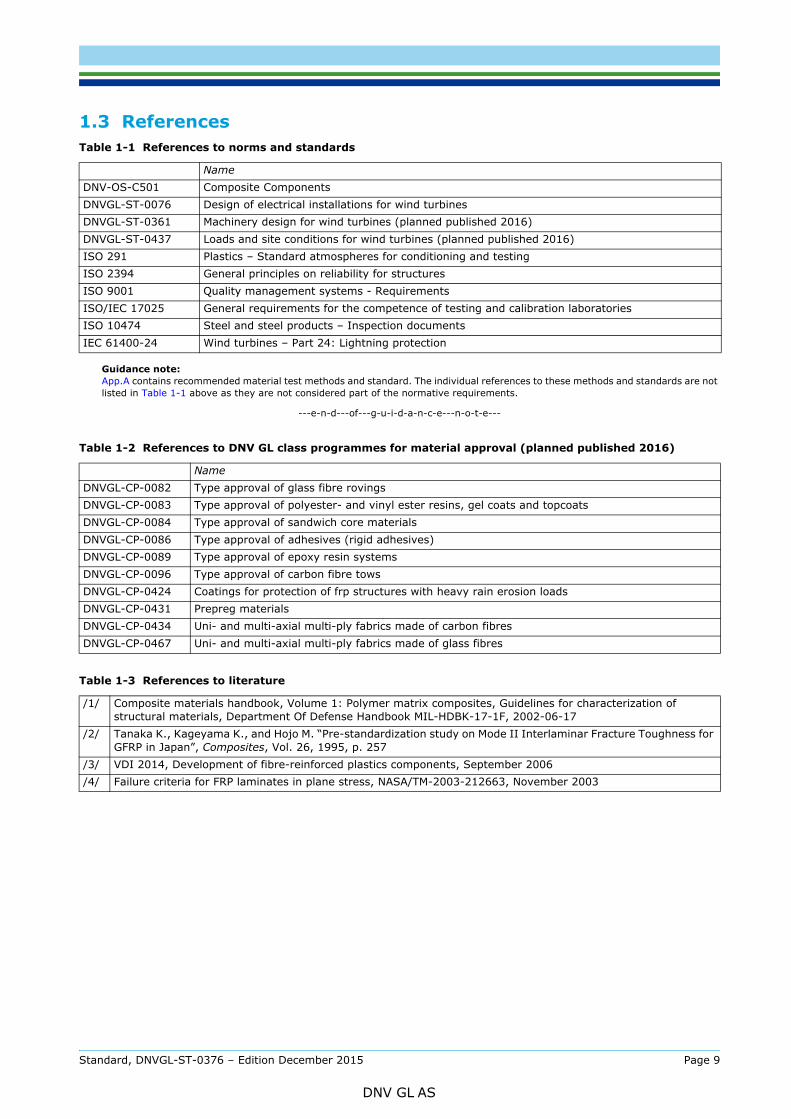
Table 1-1 References to norms and standards
NameDNV-OS-C501 Composite ComponentsDNVGL-ST-0076 Design of electrical installations for wind turbinesDNVGL-ST-0361 Machinery design for wind turbines (planned published 2016)DNVGL-ST-0437 Loads and site conditions for wind turbines (planned published 2016)ISO 291 Plastics – Standard atmospheres for conditioning and testingISO 2394 General principles on reliability for structuresISO 9001 Quality management systems - RequirementsISO/IEC 17025 General requirements for the competence of testing and calibration laboratoriesISO 10474 Steel and steel products – Inspection documentsIEC 61400-24 Wind turbines – Part 24: Lightning protection
Table 1-2 References to DNV GL class programmes for material approval (planned published 2016)
NameDNVGL-CP-0082 Type approval of glass fibre rovingsDNVGL-CP-0083 Type approval of polyester- and vinyl ester resins, gel coats and topcoatsDNVGL-CP-0084 Type approval of sandwich core materialsDNVGL-CP-0086 Type approval of adhesives (rigid adhesives)DNVGL-CP-0089 Type approval of epoxy resin systemsDNVGL-CP-0096 Type approval of carbon fibre towsDNVGL-CP-0424 Coatings for protection of frp structures with heavy rain erosion loadsDNVGL-CP-0431 Prepreg materialsDNVGL-CP-0434 Uni- and multi-axial multi-ply fabrics made of carbon fibresDNVGL-CP-0467 Uni- and multi-axial multi-ply fabrics made of glass fibres
Table 1-3 References to literature
/1/ Composite materials handbook, Volume 1: Polymer matrix composites, Guidelines for characterization of structural materials, Department Of Defense Handbook MIL-HDBK-17-1F, 2002-06-17
/2/ Tanaka K., Kageyama K., and Hojo M. “Pre-standardization study on Mode II Interlaminar Fracture Toughness for GFRP in Japan”, Composites, Vol. 26, 1995, p. 257
/3/ VDI 2014, Development of fibre-reinforced plastics components, September 2006/4/ Failure criteria for FRP laminates in plane stress, NASA/TM-2003-212663, November 2003
Standard, DNVGL-ST-0376 – Edition December 2015 Page 9
DNV GL AS
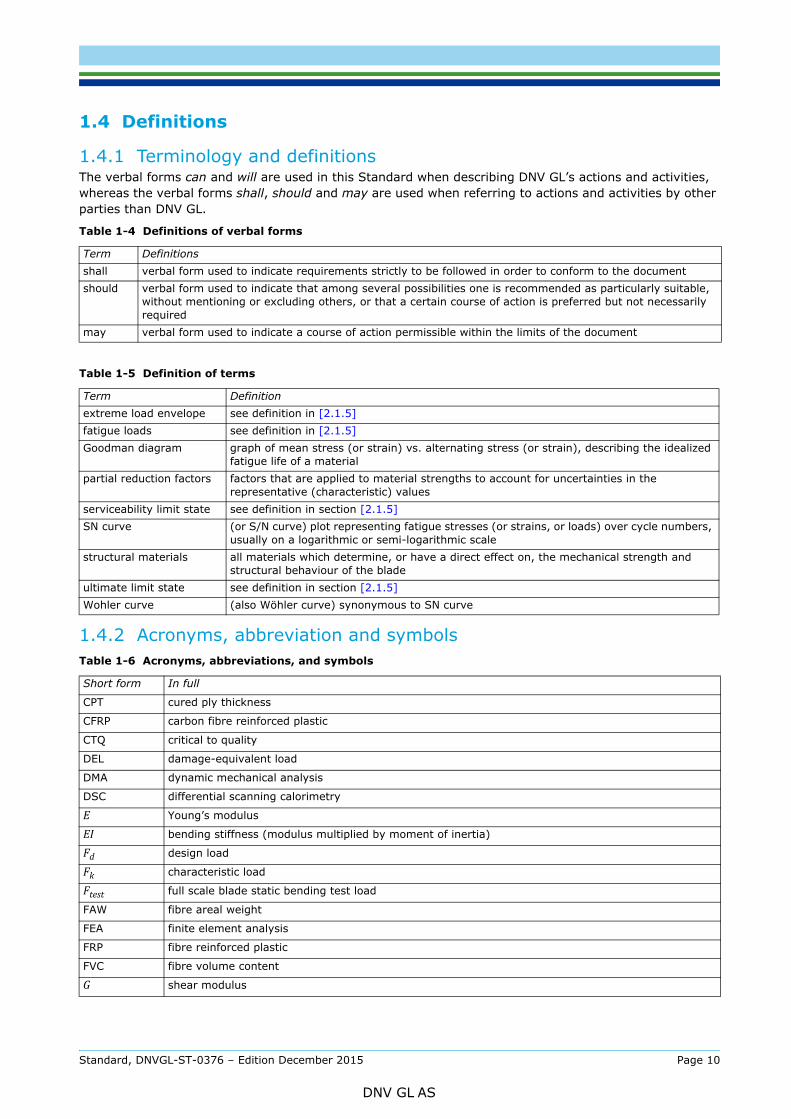
1.4.1 Terminology and definitionsThe verbal forms can and will are used in this Standard when describing DNV GL’s actions and activities, whereas the verbal forms shall, should and may are used when referring to actions and activities by other parties than DNV GL.
1.4.2 Acronyms, abbreviation and symbols
Table 1-4 Definitions of verbal forms
Term Definitionsshall verbal form used to indicate requirements strictly to be followed in order to conform to the documentshould verbal form used to indicate that among several possibilities one is recommended as particularly suitable,
without mentioning or excluding others, or that a certain course of action is preferred but not necessarily required
may verbal form used to indicate a course of action permissible within the limits of the document
Table 1-5 Definition of terms
Term Definitionextreme load envelope see definition in [2.1.5]fatigue loads see definition in [2.1.5]Goodman diagram graph of mean stress (or strain) vs. alternating stress (or strain), describing the idealized
fatigue life of a materialpartial reduction factors factors that are applied to material strengths to account for uncertainties in the
representative (characteristic) valuesserviceability limit state see definition in section [2.1.5]SN curve (or S/N curve) plot representing fatigue stresses (or strains, or loads) over cycle numbers,
usually on a logarithmic or semi-logarithmic scalestructural materials all materials which determine, or have a direct effect on, the mechanical strength and
structural behaviour of the bladeultimate limit state see definition in section [2.1.5]Wohler curve (also Wöhler curve) synonymous to SN curve
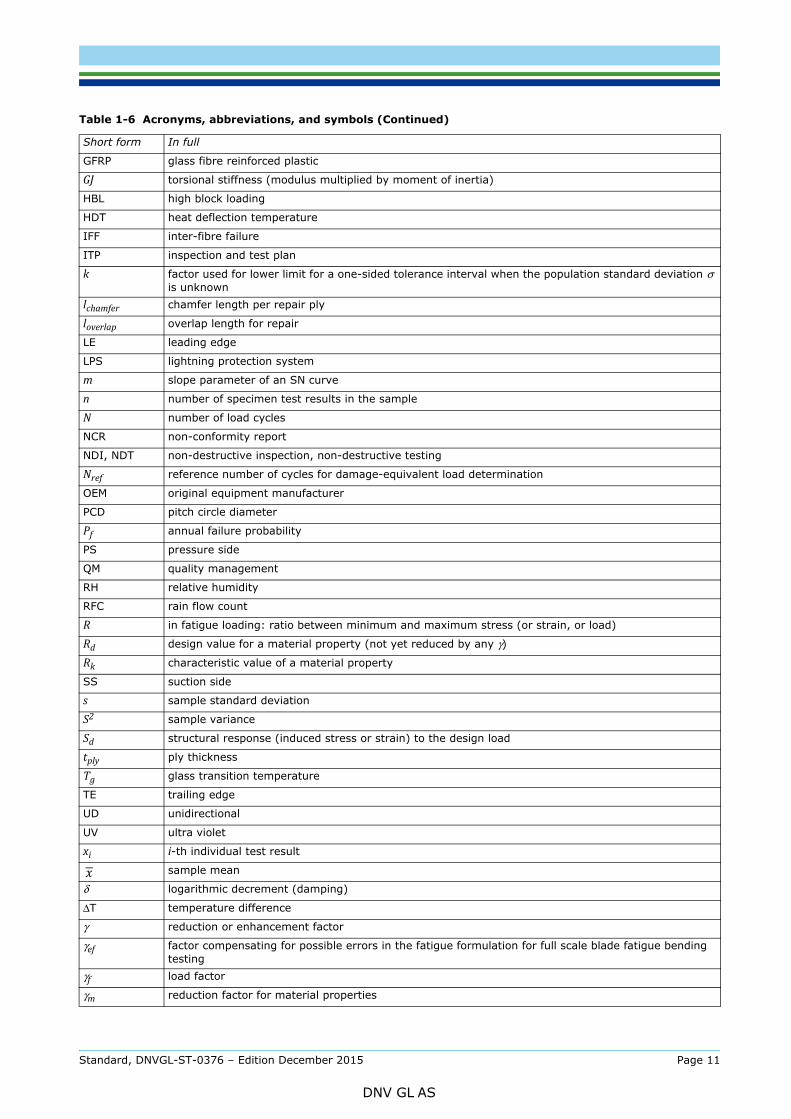
Table 1-6 Acronyms, abbreviations, and symbols
Short form In full
CPT cured ply thickness
CFRP carbon fibre reinforced plastic
CTQ critical to quality
DEL damage-equivalent load
DMA dynamic mechanical analysis
DSC differential scanning calorimetry
E Young’s modulus
EI bending stiffness (modulus multiplied by moment of inertia)
Fd design load
Fk characteristic load
Ftest full scale blade static bending test load
FAW fibre areal weight
FEA finite element analysis
FRP fibre reinforced plastic
FVC fibre volume content
G shear modulus
Standard, DNVGL-ST-0376 – Edition December 2015 Page 10
DNV GL AS
GFRP glass fibre reinforced plastic
GJ torsional stiffness (modulus multiplied by moment of inertia)
HBL high block loading
HDT heat deflection temperature
IFF inter-fibre failure
ITP inspection and test plan
k factor used for lower limit for a one-sided tolerance interval when the population standard deviation σ is unknown
lchamfer chamfer length per repair ply
loverlap overlap length for repair
LE leading edge
LPS lightning protection system
m slope parameter of an SN curve
n number of specimen test results in the sample
N number of load cycles
NCR non-conformity report
NDI, NDT non-destructive inspection, non-destructive testing
Nref reference number of cycles for damage-equivalent load determination
OEM original equipment manufacturer
PCD pitch circle diameter
Pf annual failure probability
PS pressure side
QM quality management
RH relative humidity
RFC rain flow count
R in fatigue loading: ratio between minimum and maximum stress (or strain, or load)
Rd design value for a material property (not yet reduced by any γ)
Rk characteristic value of a material property
SS suction side
s sample standard deviation
S2 sample variance
Sd structural response (induced stress or strain) to the design load
tply ply thickness
Tg glass transition temperature
TE trailing edge
UD unidirectional
UV ultra violet
xi i-th individual test result
sample mean
δ logarithmic decrement (damping)
ΔT temperature difference
γ reduction or enhancement factor
γef factor compensating for possible errors in the fatigue formulation for full scale blade fatigue bending testing
γf load factor
γm reduction factor for material properties
Table 1-6 Acronyms, abbreviations, and symbols (Continued)
Short form In full
Standard, DNVGL-ST-0376 – Edition December 2015 Page 11
DNV GL AS
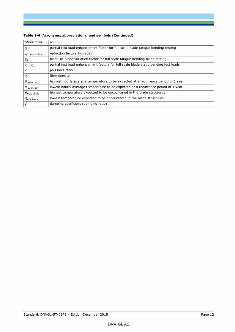
γnf partial test load enhancement factor for full scale blade fatigue bending testing
γprocess, γenv reduction factors for repair
γsf blade-to-blade variation factor for full scale fatigue bending blade testing
γ1t, γ2t partial test load enhancement factors for full scale blade static bending test loads
ν poisson’s ratio
ρf fibre density
θ1year,max highest hourly average temperature to be expected at a recurrence period of 1 year
θ1year,min lowest hourly average temperature to be expected at a recurrence period of 1 year
θmax, blade highest temperature expected to be encountered in the blade structures
θmin, blade lowest temperature expected to be encountered in the blade structures
ζ damping coefficient (damping ratio)
Table 1-6 Acronyms, abbreviations, and symbols (Continued)
Short form In full
Standard, DNVGL-ST-0376 – Edition December 2015 Page 12
DNV GL AS
2.1 Basic design assumptions
2.1.1 Design basis(1) It shall be demonstrated that the design basis is sufficient for a safe design of the wind turbine rotor blade. The design basis shall be properly documented, specifying all requirements, reference codes and standards, assumptions, and methodologies applied to the design.
(2) The design basis report shall include at least:
— reference codes and standards— design principles and assumptions:
— reference to environmental conditions, under consideration of the requirements of sections [2.1.2], [2.1.3], and [2.1.4]
— reference to design loads, under consideration of the requirements of section [2.1.5]— interfaces, under consideration of the requirements of section [2.2]— partial reduction factors and enhancement factors
— design lifetime— calculation and analysis methods— requirements for manufacturing— requirements for transport and installation— requirements for operation, maintenance, inspections, and monitoring.
(3) The scope of certification shall be specified as part of the design basis.
Guidance note:Specifying the scope of certification should e.g. include information regarding the following:
— Are the root connection bolts included in the certification?— Is the lighting protection system included in the certification?— Are manuals included in the certification?
---e-n-d---of---g-u-i-d-a-n-c-e---n-o-t-e---
2.1.2 Temperatures(1) The most severe temperatures expected to be encountered by the blade structure shall be considered for structural dimensioning, in connection with the most severe loads to be expected to occur at the same time (due to energy production, or other operational modes such as standstill or idling).
(2) The most severe ambient temperatures expected to be encountered by the blade shall be defined as follows:
Based on these ambient temperatures, the most extreme temperatures θmax, blade and θmin, blade expected to be encountered in the blade structures shall be estimated, considering the following:
— ambient temperatures— solar radiation— blade colours— heat capacity and conductivity of the blade structure— blade heating systems for de-icing/anti-icing.
(3) Without further justification, the material and testing requirements of sections [3.2.2] and [3.4], in
— θ1year,max highest hourly average temperature to be expected at a recurrence period of 1 year— θ1year,min lowest hourly average temperature to be expected at a recurrence period of 1 year.
Standard, DNVGL-ST-0376 – Edition December 2015 Page 13
DNV GL AS
considered sufficient to cover a temperature range from –30°C ≤ θmin,blade to θmax,blade ≤ +50°C.
(4) If the temperatures specified in paragraph (3) above are exceeded, further material testing and structural verification shall be carried out for extreme blade temperatures, in order to demonstrate that the blade structure at a given extreme temperature can withstand all relevant design loads. The relevant design loads in this context shall be the extreme load envelope, the serviceability limit state loads envelope, and the tower clearance load case as per section [2.1.5] (3); or, alternatively, the specific load assumptions for a given extreme temperature to be reported as part of the design basis.
(5) Only if a significant fraction of the design fatigue load spectrum is expected to occur at temperatures exceeding the ones specified in paragraph (4) above, additional justification (i.e. further material testing and structural verification) with regard to fatigue is required.
2.1.3 Specific requirements for higher temperatures(1) For temperatures exceeding the criteria given in section [2.1.2] (3), i.e. for θmax,blade > +50°C, compliance with the requirements in the following paragraphs (2) through (4) shall be demonstrated.
(2) Thermal stability of matrix and adhesive resins shall be proven as required in section [3.3.3] (2), and [3.3.7] (2), with regard to θmax,blade.
(3) For all structural properties that are susceptible to change at the given θmax,blade, further material testing (or any other appropriate proof of material properties), and structural verification in case of changing material properties, shall be carried out. This shall include at least the following:
— sandwich core shear static testing, and buckling analysis— sandwich face sheet adhesion strength testing— laminate compression static strength testing in fibre direction, and analyses for fibre failure— adhesive static strength testing, and adhesive joints analyses— bonded root inserts static strength testing (or validation based on appropriate coupon testing), and root
verification analysis.
All material testing shall be carried out at the given θmax,blade, and in conformance with the applicable requirements of section [3.4]. All structural verification analyses shall be carried out in conformance with the applicable requirements of section [2.5].
(4) Evidence shall be provided that the global mechanical characteristics of the blade at the given θmax,blade are not expected to change beyond the tolerances specified as per section [2.4.8], in order to maintain consistency with the load assumptions.
2.1.4 Specific requirements for lower temperatures(1) For temperatures below the criteria given in section [2.1.2] (3), i.e. for θmin,blade < –30°C, compliance with the requirements in the following paragraphs (2) through (4) shall be demonstrated.
(2) Through additional DMA (dynamic mechanical analysis, see section [A.2.1]) with a starting temperature of θmin,blade ≤ 10°C, it shall be ensured that no unexpected transitions of any nature occur at low temperatures that could affect the structural properties of lamination and adhesive resins.
(3) For all structural properties that are susceptible to change at the given θmin,blade, further material testing (or any other appropriate proof of material properties), and structural verification in case of changing material properties, shall be carried out. This shall include at least the following:
— sandwich core shear static testing, and buckling analysis— sandwich face sheet adhesion strength testing— laminate tension static strength testing perpendicular to fibre direction, and analyses for inter-fibre failure— laminate in-plane shear static strength testing, and analysis for inter-fibre failure— adhesive static strength testing, and adhesive joints analysis— bonded root inserts static strength testing (or validation based on appropriate coupon testing), and root
verification analysis.
Standard, DNVGL-ST-0376 – Edition December 2015 Page 14
DNV GL AS
requirements of section [3.4]. All structural verification analyses shall be carried out in conformance with the applicable requirements of section [2.5].
(4) Evidence shall be provided that the global mechanical characteristics of the blade at the given θmin,blade are not expected to change beyond the tolerances specified as per section [2.4.8], in order to maintain consistency with the load assumptions.
2.1.5 Design loads(1) The design load assumptions which are used as a basis for the design verification of the blade structure shall be specified as part of the design documentation, for example by:
— referencing blade load assumptions that are part of wind turbine load assumptions (as part of a wind turbine type certification); or by
— generic, stand-alone blade load assumptions, quantified in detail as part of the blade design documentation. In this case, the loads should be reported in connection with a wind class, and a rated turbine power.
(2) The design loads shall be specified with regard to the following limit states (see ISO 2394, in connection with DNVGL-ST-0437):
— Ultimate limit state:The ultimate limit state generally corresponds to the maximum load-bearing capacity, and includes rupture of critical parts of the blade structure and its connections, for instance by: exceedance of ultimate strength; loss of stability (buckling); fatigue
— Serviceability limit state:The serviceability limit state is determined by various limiting values which are oriented towards the normally envisaged use of the wind turbine. Limits to be observed are for instance: deformation of the rotor blade towards the turbine tower; stresses and strains.
(3) The following sets of design loads shall be specified as basis for the blade design:
— extreme load envelope (based on ultimate limit state loads)— fatigue loads— serviceability limit state loads envelope (for inter-fibre failure analysis)— tower clearance load case (based on serviceability limit state loads).
For all loads, the applied load factors shall be reported.
(4) The extreme load envelope shall be specified so that it encompasses all applicable design load cases, expressed as bending moment distribution over length in all relevant directions, as well as torsional moments, axial forces, and shear forces. For reporting and analysis purposes, it is acceptable to discretise the load envelope in a way that it comprises at least 12 equally distributed bending moment directions (i.e. in steps of 30°). [B.1] illustrates a format suitable for reporting and for use in subsequent analyses.
(5) As an alternative to the requirements in paragraph (4) above, the extreme load envelope may be expressed in a reduced form as bending moment distribution in the main directions, i.e. positive and negative flapwise and edgewise bending moments. [B.2] illustrates a format suitable for reporting and for use in subsequent analyses.
(6) The fatigue loads shall be specified as bending moments, and either as full time series, or as rain flow count matrices (RFC matrices, sometimes also called “Markov” matrices). Such RFC matrices shall contain cycles count numbers associated with mean-range bins.
(7) RFC matrices shall be reported for evenly distributed bending moment directions in steps of no less than 30° for the blade body, and in steps of no less than 15° for the blade root.
(8) In addition to paragraph (6) above, for documentation and comparison purposes, the bending moment range from a damage-equivalent constant range spectrum at Nref = 107 load cycles (damage-equivalent load, DEL) shall be reported for different magnitudes of the SN curve slope parameter m (typically for m = 4.14), and for at least 12 equally distributed bending moment directions (i.e. in steps of 30°).
Standard, DNVGL-ST-0376 – Edition December 2015 Page 15
DNV GL AS
form as bending moments in the main directions only, i.e. flapwise and edgewise bending moments.
(10) The serviceability limit state loads envelope, if required for IFF analysis, shall be specified in the same way as described in paragraph (4) above.
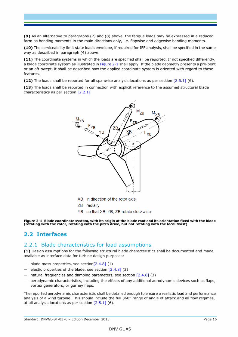
(11) The coordinate systems in which the loads are specified shall be reported. If not specified differently, a blade coordinate system as illustrated in Figure 2-1 shall apply. If the blade geometry presents a pre-bent or an aft-swept, it shall be described how the applied coordinate system is oriented with regard to these features.
(12) The loads shall be reported for all spanwise analysis locations as per section [2.5.1] (6).
(13) The loads shall be reported in connection with explicit reference to the assumed structural blade characteristics as per section [2.2.1].
Figure 2-1 Blade coordinate system, with its origin at the blade root and its orientation fixed with the blade (rotating with the rotor, rotating with the pitch drive, but not rotating with the local twist)
2.2 Interfaces
2.2.1 Blade characteristics for load assumptions(1) Design assumptions for the following structural blade characteristics shall be documented and made available as interface data for turbine design purposes:
— blade mass properties, see section[2.4.8] (1)— elastic properties of the blade, see section [2.4.8] (2)— natural frequencies and damping parameters, see section [2.4.8] (3)— aerodynamic characteristics, including the effects of any additional aerodynamic devices such as flaps,
vortex generators, or gurney flaps.
The reported aerodynamic characteristic shall be detailed enough to ensure a realistic load and performance analysis of a wind turbine. This should include the full 360° range of angle of attack and all flow regimes, at all analysis locations as per section [2.5.1] (6).
Standard, DNVGL-ST-0376 – Edition December 2015 Page 16
DNV GL AS
design loads.
2.2.2 Root attachment(1) All parameters that are necessary to describe how the blade is attached to the wind turbine shall be specified. For a circular bolted root connection, as it is most commonly applied in state-of-the-art wind turbine designs, this shall include at least the following:
— bolt circle diameter (pitch circle diameter, PCD)— number of attachment bolts— dimension of bolts, thread form, thread manufacturing method, washer, nut— strength class of bolts according ISO 898— corrosion protection of bolts.
(2) Root bolt installation parameters shall be reported, at least including:
— nominal pre-tension force of bolts in kN, tolerances (maximum and minimum force in kN)— pre-tensioning method.
(3) The design assumptions applied for the root attachment analysis shall be documented, at least including:
— design details and stiffness assumptions of the adjacent structures (i.e. blade root and pitch bearing) for evaluating bolt load factor and bolt bending (or, alternatively, conservative assumptions regarding bolt load factor and bolt bending)
— assumptions regarding the circumferential distribution of axial forces acting on the connection bolts as a result from blade bending.
2.3 Load comparisons(1) In case of changes in the design loads, a load comparison may be carried out in order to show that the blade continues to be compliant with the requirements of this standard. This can e.g. occur in the following situations:
— Design load assumptions change as part of an iterative design process, or due to modifications in the wind turbine design.
— Design load assumptions change due to the characteristics of a specific wind park site.— Rotor blades are designed with a given set of design loads, and then integrated into a wind turbine
design for which the design loads are not explicitly identical.
(2) Provided that the blade design has previously been found compliant with regard to the requirements of this standard, based on a given initial set of design loads, the blade design continues to be compliant if one of the following can be demonstrated by a load comparison:
— The new design loads are lower than the initial ones.— The load exceedance is limited in magnitude or is confined to less critical areas of the blade, and the
design calculations with the initial loads have revealed sufficient reserve factors to compensate for this.
Guidance note:Such load comparisons should also refer to the initial set of design loads, which is the one that has been the basis for the original blade certification.
When comparing load exceedances and reserve factors, special attention should be given to failure modes where non-linearities may be present. For example, extrapolation of stress reserve factors for the new load envelope may not be permissible for non-linear FEA-based buckling calculations.
---e-n-d---of---g-u-i-d-a-n-c-e---n-o-t-e---
If the new design loads exceed the initial ones to a significant extent, it shall be demonstrated (usually by new design analyses) that the blade structure is still compliant with certification requirements.
(3) Load comparisons shall be carried out in all load directions applied in the initial certification (i.e. usually
Standard, DNVGL-ST-0376 – Edition December 2015 Page 17
DNV GL AS
section [2.1.5] (3). In this context, a fatigue load comparison based on damage-equivalent loads may be acceptable, as long as the inaccuracies resulting from this can be considered small.
Guidance note:For example, the inaccuracies cannot be considered small if the new loads are associated with an increased rated power of the turbine. In this case, the mean stress influence on the fatigue strength in flapwise bending is expected to become more critical. As mean stresses are usually not considered in damage-equivalent loads, they have to be included in the load comparison in an appropriate manner.
---e-n-d---of---g-u-i-d-a-n-c-e---n-o-t-e---
(4) In addition, it shall be demonstrated that the blades have been sufficiently loaded during full scale blade testing when compared to the new design loads, and under consideration of the applicable requirements of section 4. Otherwise, new full scale blade testing shall be carried out. As an exception to this, new full scale blade testing may be omitted if the load exceedance is limited in magnitude, does only affect a limited area of the blade, and does not affect any critical areas in the blade.
Guidance note:For example, omitting new blade tests may be acceptable in the following cases:
a) The increase of the design loads (as compared to the initial ones) is not higher than 10% (static test) or 5% (fatigue test), and:— the areas of the blade affected by the load exceedance are limited in size (i.e. the total area is not more than one third of
the blade length)— residual safety (strength/stability) in the affected area was larger than 1.3— no cracks, elastic buckling, non-linear behaviour etc. were observed in the initial test
or
b) The increase of the design loads (as compared to the initial ones) is not higher than 5% (static test) or 2.5% (fatigue test), and:— residual safety (strength/stability) in the affected area was larger than 1.1— no cracks, elastic buckling, non-linear behaviour etc. were observed in the initial test.
---e-n-d---of---g-u-i-d-a-n-c-e---n-o-t-e---
Also, it may be acceptable to carry out intermediate level testing as a substitute to full scale testing (see section [2.6.3]).
In this context, fatigue test loads may be compared to design loads based on damage-equivalent loads, as long as the inaccuracies resulting from this can be considered small.
2.4 Design requirements
2.4.1 Drawings(1) A master document should list all relevant drawings and descriptions of the blade design.
(2) All drawings and descriptions shall have an explicit document number, title, and revision number.
(3) The design documentation should specify all relevant requirements and give all information needed to enable the blade or component manufacturer to meet the assumed blade properties in terms of functionality and structural integrity.
(4) Drawings shall include unambiguous references for the materials used, according to section [3.2.1] (2).
2.4.2 General requirements for design principles and design details(1) When designing the laminate, its maximum thickness shall not exceed any limits imposed by manufacturing constraints, such as maximum permissible heat generation during curing; or number of layers which can be infused and deaerated properly (i.e. so that all manufacturing requirements such as fibre volume fraction or wrinkle tolerances are met).
(2) Transitions between different thicknesses of laminate shall be made gradually. Their effect on the local strength of the structure shall be taken into account, in particular for relatively thick laminate layers.
Guidance note:In some cases, it may sufficiently conservative to select a minimum step length based on a simple shear load transfer criterion,
e.g. , where L is the minimum step length in mm, S the average laminate layer strength in MPa, and t the laminate layer thickness in mm.
= 10 ∙
Standard, DNVGL-ST-0376 – Edition December 2015 Page 18
DNV GL AS
---e-n-d---of---g-u-i-d-a-n-c-e---n-o-t-e---
(3) If the joining or cutting of reinforcement layers is unavoidable, e.g. in the case of complicated mouldings, then cut edges shall overlap or reinforcement strips shall be provided. In the butt or seam region of laminates, any reinforcement layer shall overlap by a specified minimum step length, as per paragraph (2) above.
(4) In general, multiple layer overlap at the same position should be avoided. In case of a multiple layer overlap at one position the impact of the fibre undulation on the laminate strength shall be specified and analysed by the designer, and its strength shall be proven (e.g. by subcomponent testing).
(5) Butt joints at the same position should only be allowed in case of at least five undisturbed layers in between. For spar caps made of UD material, any split of reinforcement layers has to be specified and analysed by the designer. Any other deviations shall be specified, analysed and, if applicable, tested in agreement with DNV GL.
(6) The tapering of core materials shall be specified by the designer, and analysed in relation to magnitude and direction of local loading.
Guidance note:In some cases, it may be sufficiently conservative to select the following taper angles:
— not steeper than 1:5 in the main load-carrying direction— not steeper than 1:10 in areas where load carrying components are placed on top of core material— not steeper than 1:3 perpendicular to the main load-carrying direction.
---e-n-d---of---g-u-i-d-a-n-c-e---n-o-t-e---
(7) As a rule, bond line thicknesses should not be bigger than 10 mm. Changes in width and thickness of bond lines should be designed with smooth transitions.
(8) At start and run out of shear webs, the stiffness of the shear web should be reduced by proper means (e.g. round cut-out, and stepping of reinforcing laminate) to avoid stress concentrations in the shell laminate, in particular for supporting shear webs in the area of sandwich panels.
(9) If highly curved laminate features are part of the design (e.g. at shear web flanges), their smallest radius should not be below 25 mm. In case a smaller radius is implemented, is should be shown that laminates and adhesive joints will not be adversely affected by such a small radius (e.g. due out-of-plane distortion under fatigue loading).
(10) If prefabricated parts are part of the design, these should be implemented in a way that the transfer of the main loads follows a double lap shear path.
(11) Core materials used apart from sandwich panels, e.g. for the purpose of positioning in the trailing edge or tip area, shall be capable of withstanding local static and fatigue loading.
(12) Core materials shall be carefully protected against penetration by extraneous media (e.g. moisture).
(13) Where environmental influences (such as sun light, salt water, or hydraulic fluids or oil) are expected to adversely affect the adhesive material or the bond line, adhesive joints exposed to such influences shall be protected by suitable means.
(14) The possibility of galvanic corrosion (e.g. in the presence of metals and carbon fibres) shall be avoided by suitable means.
2.4.3 Design requirements for manufacturing tolerances(1) As a part of the design, all relevant manufacturing tolerances (or an upper or a lower limit value where applicable) shall be specified and documented (e.g. in the drawings, or in design specifications).
(2) The tolerances shall be consistent with the design assumptions for material properties (as per section [3.5.6]) and the selected partial reduction factors (as per section [2.5]).
(3) The tolerances shall be consistent with the manufacturing capabilities, the quality acceptance criteria, and the selected CTQs (as per section [5.5]).
Standard, DNVGL-ST-0376 – Edition December 2015 Page 19
DNV GL AS
— shell and web fabric positioning in transversal and longitudinal directions— angle misalignment (in plane and out of plane) for shell and web fabrics— girder fabric positioning in transversal and longitudinal directions— angle misalignment (in plane and out of plane) for girder fabrics— shell and web fabric overlap in transversal and longitudinal directions— girder fabric overlap in transversal and longitudinal directions— positioning and orientation of pre-manufactured components in the mould— core positioning in transversal and longitudinal directions— gaps between core panels— height misalignment between core panels in transversal and circumferential directions— core chamfering angle— positioning of the bolt circle diameter in the root flange, i.e. distances between bolt circle diameter and
outer surface / inner surface of the blade— longitudinal wrinkles in the root laminate— bond line thickness and width— trim radius of bond line edges— laminate fibre volume content, and void content (including individual void dimensions, and total void
area for a given laminate area)— adhesive void content (including individual void dimensions, and total void area for a given bond area)— degree of cure (Tg, hardness, etc.).
2.4.4 Design requirements for non-conformities and repairIf standard procedures for handling non-conformities, or standard repairs, are considered in the design, these shall be specified in accordance with section [5.7.6] and Sec.8, and properly documented in the design documentation.
2.4.5 Geometrical interference analysisAs part of the design, the geometry of all blade sub-assemblies shall be analysed for potential interference during the assembly process (such as sandwich thickness and core chamfers at the trailing edge, LPS receptors, etc.).
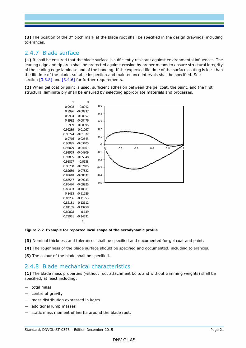
2.4.6 Aerodynamic surface contour(1) The aerodynamic surface contour shall be specified and documented at all analysis locations as per section [2.5.1] (6), at least including:
— local shape of the aerodynamic profile, including bulk data for profile definition (see Figure 2-2 for illustration)
— chord length— thickness— twist angle— pre-bend / location of pitch axis.
(2) Tolerances shall be specified and documented for the following dimensions:
— shape of the aerodynamic surface contour: radius of the profile at the leading edge, thickness, chord length
— twist angle— pre-bend / location of pitch axis— blade length (including information about how the blade length is defined, especially for pre-bent
blades).
Standard, DNVGL-ST-0376 – Edition December 2015 Page 20
DNV GL AS
tolerances.
2.4.7 Blade surface(1) It shall be ensured that the blade surface is sufficiently resistant against environmental influences. The leading edge and tip area shall be protected against erosion by proper means to ensure structural integrity of the leading edge laminate and of the bonding. If the expected life time of the surface coating is less than the lifetime of the blade, suitable inspection and maintenance intervals shall be specified. See section [3.3.8] and [3.4.6] for further requirements.
(2) When gel coat or paint is used, sufficient adhesion between the gel coat, the paint, and the first structural laminate ply shall be ensured by selecting appropriate materials and processes.
Figure 2-2 Example for reported local shape of the aerodynamic profile
(3) Nominal thickness and tolerances shall be specified and documented for gel coat and paint.
(4) The roughness of the blade surface should be specified and documented, including tolerances.
(5) The colour of the blade shall be specified.
2.4.8 Blade mechanical characteristics(1) The blade mass properties (without root attachment bolts and without trimming weights) shall be specified, at least including:
— total mass
— centre of gravity
— mass distribution expressed in kg/m
— additional lump masses
— static mass moment of inertia around the blade root.
1 00.9998 -0.00120.9996 -0.002370.9994 -0.003570.9992 -0.00476
0.999 -0.005950.99289 -0.010970.98224 -0.01872
0.9716 -0.026430.96095 -0.034050.95029 -0.041610.93963 -0.049090.92895 -0.056480.91827 -0.06380.90758 -0.071050.89689 -0.078220.88618 -0.085320.87547 -0.092330.86476 -0.099250.85403 -0.10611
0.8433 -0.112860.83256 -0.119530.82181 -0.126120.81105 -0.132590.80028 -0.1390.78951 -0.14531
… …
-0.5
-0.4
-0.3
-0.2
-0.1
0
0.1
0.2
0.3
0.4
0.5
0 0.2 0.4 0.6 0.8 1
Standard, DNVGL-ST-0376 – Edition December 2015 Page 21
DNV GL AS
tolerance of ±3% percent shall apply. The characteristics of the trimming weights (location and maximum mass) shall be specified. The total mass of the root attachment bolts should be specified.
(2) The elastic properties of the blade shall be specified at all analysis cross sections as per section [2.5.1] (6), at least including:
— bending stiffness distribution, expressed as EI, in flap and edge direction (i.e. as EIflap and EIedge), as well as in the principal axes (i.e. as EI1 and EI2) torsional stiffness distribution, expressed as GJ.
(3) The natural frequencies and damping parameters for the following vibration modes shall be specified:
— first and second flapwise bending mode— first and second edgewise bending mode— first torsional mode.
For the frequencies, the nominal values shall be documented together with tolerances; without further justification, a tolerance of ±5% percent shall apply. For damping parameters, no specific requirements with regard to accuracy or tolerances apply.
2.4.9 Lightning protection(1) The blade shall be equipped with a lightning protection system (LPS) in compliance with the requirements specified in DNVGL-ST-0076 (or, alternatively, in compliance with similar standards, such as IEC 61400-24).
(2) The LPS should be installed as close as possible to the neutral bending axis of the blade, in order to avoid interference with mechanical loading of the blade.
2.4.10 Further documentation (manuals)Any further information that is relevant for a proper handling and operating of the blade shall be specified in appropriate documents (e.g. manuals) as part of the blade design. These shall at least include:
— blade handling, transport, and installation procedures, as per section [6.1]— instructions for standard repairs (if any)— instructions for operation— instructions for maintenance and inspection, as per Sec.7.
In addition, instructions for decommissioning and disposal should be included.
2.5 Verifications analyses
2.5.1 General(1) The purpose of the design verification is to demonstrate by engineering analyses that the blade structure is capable of withstanding the design loads specified as per section [2.1.5].
(2) Each relevant failure mode shall be analysed separately. The scope and the requirements for the analyses for each relevant failure mode are described in detail in this section [2.5].
(3) The analyses shall demonstrate that a suitable design criterion is fulfilled for each relevant failure mode. The design criterion shall have the following general form:
where:
Sd structural response (induced stress or strain) to the design loadγf load factor
∙ ≤
Standard, DNVGL-ST-0376 – Edition December 2015 Page 22
DNV GL AS
(4) All verification analyses shall be carried out for all relevant design load cases or for selected extreme load conditions (envelope), and for the entire fatigue load spectrum or a suitable reduction of the same (e.g. rain flow count matrices), in compliance with section [2.1.5] and with the specific requirements for each type of analysis as specified in this section [2.5].
(5) All verification analyses shall be carried out based on material values established as per section [3.5]. For each type of verification, the material values shall be reduced by a reduction factor γm determined as follows:
where:
The base factor shall be
γm0 = 1.2
for all analyses. The partial reduction factors γmc and γm1 2,... shall be specified for each failure mode in accordance with the requirements of the remainder of this section [2.5]; each partial reduction factor shall apply as specified herein, unless different values are demonstrated to be appropriate and agreed with DNV GL.
Guidance note 1: is dedicated to account for reversible changes in the material properties over the blade temperature range as compared to material properties determined based on testing at room temperature.
---e-n-d---of---g-u-i-d-a-n-c-e---n-o-t-e---
Guidance note 2:The magnitude of γm0 ⋅ γmc = 1.2 ⋅ 1.08 = 1.3 as specified in sections [2.5.2] through to [2.5.5] may be interpreted as a reduction factor correlating to an annual failure probability of PF =10–4 of the blade. This may serve as a reference for reliability-based design methods.
According to DNV-OS-C501, a PF of 10–4 relates to a composite structure whose failure implies low risk of human injury and minor environmental and economic consequences.
---e-n-d---of---g-u-i-d-a-n-c-e---n-o-t-e---
(6) All verification analyses shall be carried out over the entire blade length, and over the entire chordwise circumference. The model discretization shall fulfil all of the following requirements:
— Between root and location of largest chord length, a sufficient number of cross sections shall be analysed (the number should be chosen in a way that the geometrical change between adjacent cross sections could be assumed as linear).
— Between root and location of largest chord length, the spanwise distance between two analysis sections shall not be larger than the smallest chord length between the two sections.
— Between location of largest chord length and tip, a sufficient number of cross sections shall be analysed, such that the spanwise distance between two analysis sections is sufficiently small (without further justification, a distance of 1.5 times the smallest chord length of the two sections may be considered sufficiently small). The number of cross sections to be analysed shall not be be less than 10 in any case.
— All critical areas (such as girder start and end, ramp-ups, start and end of glueing lips, shear web start and end, shear web ellipse) shall be considered.
Fk characteristic loadRd characteristic material design valueγm reduction factor
γm0 base factorγmc partial reduction factor for criticality of failure modeγm1 partial reduction factor for irreversible long-term degradationγm2 partial reduction factor for temperature effects (reversible effects)γm3 partial reduction factor for manufacturing effectsγm4 partial reduction factor for the accuracy of analysis methodsγm5 partial reduction factor for the accuracy of load assumptions.
= 0 ∙ ∙ 1 ∙ 2 ∙ 3 ∙ 4 ∙ 5
Standard, DNVGL-ST-0376 – Edition December 2015 Page 23
DNV GL AS
as girders, sandwich shells, leading edge and trailing edge stiffeners) can be differentiated, and that the locations of highest stresses or strains are sufficiently represented.
(7) If an FEA method is applied, it shall be demonstrated that the selected model configuration is suitable (i.e. in terms of element types, mesh density, connecting elements, solver settings, mesh convergence, etc.).
(8) The verifications for fibre failure and for inter-fibre failure strength can be provided in the form of strain or stress analyses. In the case of strain or stress data not retrieved from FEA calculations, it has to be demonstrated that the assumptions for the calculation model are appropriate, and that the applied methods are capable of modelling all relevant effects in the blade structure (e.g. including secondary effects like root ovalization and out-of-plane deformation).
Guidance note:The assumptions for the suitability of a beam theory model are considered to be inappropriate in a blade’s region with significant geometrical transitions (e.g. between the cylindrical root part and the location of maximum chord). Here, a beam theory model may be used for analyses without further justification if a residual safety of 1.25 on strains / stresses is given.
---e-n-d---of---g-u-i-d-a-n-c-e---n-o-t-e---
2.5.2 Fibre failure (short term strength)(1) The blade laminate shall be verified for fibre short-time failure at all analysis locations as per section [2.5.1] (6), based on the extreme load envelope as per section [2.1.5] (3). A suitable failure criterion shall be specified and applied. In general, a simple criterion based on strains or stresses is acceptable, applied in each fibre direction.
(2) The following partial reduction factors shall apply:
Criticality of failure mode
Long-term degradation
Temperature effects
γm2 = 1.1 for all analyses
Manufacturing effects
Accuracy of analysis methods
γm4 = 1.0 for all analyses
Accuracy of load assumptions
2.5.3 Fibre failure (fatigue strength)(1) The blade laminate shall be verified for fibre fatigue failure at all analysis locations as per section [2.5.1] (6), based on the fatigue loads as per section [2.1.5] (3). A suitable failure criterion shall be specified and applied. In general, a failure criterion based on linear damage accumulation is acceptable.
(2) The analysis shall take into account the effect of mean stresses (or strains) resulting from the fatigue loads. This shall be achieved by using specific material SN curves for a range of different R ratios.
γmc = 1.08 for all analyses
γm1 = 1.2 resin systems based on epoxy1.3 resin systems based on polyester, vinyl ester, and polyurethane
γm3 = 1.0 if section [3.5.6] (3) is fulfilled (manufacturing effects quantified by tests)1.1 if section [3.5.6] (4) is fulfilled (manufacturing effects quantified)1.3 if section [3.5.6] (5) is fulfilled (manufacturing effects considered)
γm5 = 1.0 if loads in at least 12 directions according section [2.1.5] (4) are applied1.2 if the analysis is carried out in only 4 main directions according section [2.1.5] (5)
Standard, DNVGL-ST-0376 – Edition December 2015 Page 24
DNV GL AS
(or strains) may be applied by assuming a linear influence (linear Goodman diagram). See App.C for details.
(4) The following partial reduction factors shall apply:
Criticality of failure mode
γmc = 1.08 for all analyses
Long-term degradation
Temperature effects
γm2 = 1.0 for all analyses
Manufacturing effects
Accuracy of analysis methods
Accuracy of load assumptions
2.5.4 Buckling and stability(1) All parts of the blade, such as spar caps, shells, ribs, and shear webs, shall be verified for buckling failure at all analysis locations as per section [2.5.1] (6); localized instability (such as face sheet buckling) shall also be verified. The analyses shall be performed based on the extreme load envelope as per section [2.1.5] (3).
(2) Two alternative approaches may be used for the analysis of buckling problems:
— the analysis of isolated components of a standard type, e.g. tubular sections, beams, plates and shells, of a simple shape; or
— the analysis of the entire structure or complex component.
(3) Buckling analyses may be carried out by either analytical or numerical methods. These analyses may be applied to either geometrically perfect structures in linear analyses or geometrically imperfect structures in non-linear analyses.
(4) When a buckling analysis is performed, particular attention shall be given to the definition of the boundary conditions.
(5) For analytical buckling analyses, the equations and boundary conditions used shall be documented.
(6) For non-linear FEA, a step-by-step analysis with at least 10 load steps shall be carried out, with geometrical non-linearities included in the model. The direction of loads applied to the model should be consistent with the methods used for determining the design load assumptions. Sensitivity to imperfections shall be properly accounted for. The reduction factor γm may be applied to the load; the inaccuracy
γm1 = 1.1 resin systems based on epoxy1.2 resin systems based on polyester, vinyl ester, and polyurethane
γm3 = 1.0 if section [3.5.6] (3) is fulfilled (manufacturing effects quantified by tests)1.1 if section [3.5.6] (4) is fulfilled (manufacturing effects quantified)1.3 if section [3.5.6] (5) is fulfilled (manufacturing effects considered)
γm4 = 1.0 specific material SN curves for a range of different R ratios are used1.25 if simplified analysis according section [2.5.3] (3) is applied
γm5 = γm5a ⋅ γm5bγm5a = 1.0 if loads as time series or RFC matrices according to section [2.1.5] (6) are applied
1.3 if damage-equivalent loads are applied instead γm5b = 1.0 if loads in at least 6 directions according to section [2.1.5] (7) are applied
1.2 if the analysis is carried out in only two main directions (flapwise and edgewise)
Standard, DNVGL-ST-0376 – Edition December 2015 Page 25
DNV GL AS
for the following failure criteria:
— Buckling shall not occur at a load level low enough to affect the fatigue verification as per section [2.5.3]. Without further analysis, the fatigue verification can be assumed unaffected as long as strains are linear up to the magnitude of loads relevant for fatigue analyses.
— When assessing the results of the nonlinear FEA, it shall be demonstrated that all design criteria are met under the fully loaded condition. In particular, the failure criteria for fibre failure as specified in sections [2.5.2] shall be checked; and in addition to that, the failure criteria for delamination between the sandwich core and the laminate as well as peeling forces at bonded connections inflicted by out-of-plane deformation shall be verified.
Guidance note:The sensitivity to imperfections may be accounted for by applying a stress-free pre-deformation affine to the 1st linear buckling eigenform to the structure, even though it is not an entirely accurate method. Other methods may be equally appropriate.
---e-n-d---of---g-u-i-d-a-n-c-e---n-o-t-e---
(7) The following partial reduction factors shall apply:
Criticality of failure mode
γmc = 1.08 for all analyses
Long-term degradation
Temperature effects
Material and production tolerances
Model factor
Accuracy of load assumptions
(8) For applying a γm4 =1.0, the validation through full scale testing shall fulfil the following requirements:
— Test loads shall be representative for those design loading conditions under which the most severe non-linear strain response is expected.
— The magnitude of the test loads shall be equivalent to the design extreme load envelope as per section [2.1.5] (3), multiplied by the applicable reduction factors γm, in order to confirm the structural response of the blade as it is predicted by the model under validation.
— If the tests are performed on structural components or samples, instead of a full scale blade, they shall comply with the general requirements in section [2.5.16].
γm1 = 1.0 if degradation effects on stiffness are measured, or adequately taken into consideration1.05 if the stiffness degradation effects are not considered
γm2 = 1.0 if temperature effects are considered1.05 if temperature effects are not considered
γm3 = 1.0 if using material properties that take into account design tolerances (such as variations in laminate or core material properties) 1.1 if using nominal material properties
γm4 = 1.0 if the non-linear FEA is validated by full scale tests1.05 if a non-linear FEA is performed1.25 if a linear FEA is performed modelling the full blade1.4 if a linear FEA is performed analysing selected cross sections1.5 if the buckling analysis is performed using analytical methods
γm5 = 1.0 if loads in at least 12 directions according to section [2.1.5] (4) are applied1.2 if the analysis is carried out in only 4 main directions according to section [2.1.5] (5)
Standard, DNVGL-ST-0376 – Edition December 2015 Page 26
DNV GL AS
DNV GL.
(9) The results of such validation tests shall be evaluated for the following criteria:
— The representative test loads shall not lead to permanent damage on the blade.— In order to ensure that buckling does not occur at a load level low enough to affect the fatigue
verification analysis, it shall be demonstrated that the strain and deflection response of the blade as measured during the test is linear up to the magnitude of loads relevant for fatigue analyses; see also section [2.5.4] (6).
— The strain and deflection measurements shall confirm the theoretical results, within appropriate tolerances as per section [4.14.2] (3).
2.5.5 Adhesive joints(1) All bonded parts of the blade, such as trailing edge joint, leading edge joint, and bonds between shear webs and shells, shall be verified for bond failure at all analysis locations as per section [2.5.1] (6), based on the extreme load envelope as well as the fatigue loads, as per section [2.1.5] (3). Adhesive joints comprising dissimilar substrates, such as composite to metal interfaces, or laminates with different elastic properties, shall also be handled according to this section.
(2) Suitable failure criteria shall be specified and applied in connection with analytical calculations or finite element analyses. All relevant failure modes applicable to adhesive joints shall be evaluated including the effects of stress/strain concentrations due to geometrical discontinuities/transitions. Adhesive joints along the blade may undergo different loading conditions which may imply different failures modes. Peeling effects, e.g. from out-of-plane deformation, as well as longitudinal strains shall be considered in combination with the acting shear forces.
Guidance note:Adhesives joints exhibit complex failure modes due to complex loading and susceptibility to manufacturing defects. The following failures should be considered:
— Adhesive/adherent interface failureThis failure is characterized by the failure at the adhesive and the adherent interface, i.e. interface failure. An interface failure is one of weakest failure modes and should be avoided. This failure mode is caused by poor adherent preparation and/or incompatible adhesive, among other causes. An interface crack may subsequently be loaded by a mix of shear and peeling stresses.
— Adhesive failureThis failure is characterized by the failure at the adhesive, i.e. cohesive failure. Adhesives can have a nonlinear behaviour with large strains to failure, thus it may experience ductile failure.
— Adherent failureThis failure is characterized by the failure of the adherent, i.e. the adhesive is stronger than the adherents. The failure modes are the same as for a composite laminate, matrix or fibre failure. For additional information of composite laminate failure modes, see section [2.5.2], [2.5.3], and [2.5.13].
---e-n-d---of---g-u-i-d-a-n-c-e---n-o-t-e---
(3) The following aspects shall be taken into consideration:
— The design of adhesive joints shall consider parameters such as selection of adhesive, surface preparation, adhesive failure modes, mismatch of stiffness properties, etc.
— Because adhesives are of a variety of types (e.g. epoxy based, polyurethane, acrylic, polyester, etc.), it shall be ensured that the chosen adhesive is compatible with the blade material system; the type of adhesive and its mechanical properties will have an influence on the expected failure mode.
— The selected adhesive shall be suitable for extreme and operating temperatures and environmental conditions.
(4) The design verification of adhesive joints shall follow one of the following approaches:
— Stress approach:This shall be based on shear, axial, and peel stress limits, derived from demonstrated test and experience. For fatigue analysis, a stress-life approach shall use a reliable SN curve determined experimentally, or analytically.
Standard, DNVGL-ST-0376 – Edition December 2015 Page 27
DNV GL AS
A stress based approach shall be used to identify those areas in adhesive joints where fracture mechanics considerations shall be applied. For the fracture mechanics considerations, a crack shall be considered and it shall be proven that it will not grow under the design loads, i.e. that the strain energy release rate is below the critical strain energy release rate for crack propagation (damage tolerance approach). Tests shall be performed in order to determine the critical strain energy release rate for crack propagation. Mode I fracture dominates over mode II, and designing a composite adhesive joint for mode I dominated loading is considered conservative.
(5) Sufficient safety against creep shall be demonstrated either by
— establishing design values by appropriate tests; or— analytical methods based on material creep limits obtained from testing (as per section [3.4.5] (3); or— showing that the design is insensitive to creep.
(6) Adhesive joints are strongly dependent on bond line thickness, manufacturing-induced defects, quality of surface and preparation, mix ratios, etc. The design of an adhesive joint is a complex process that involves complicated failure modes. In order to overcome the complexities involved in the adhesive joint design and known variability in strength properties, the characteristic strength of the material has to be lowered by the partial reduction factors.
(7) The following partial reduction factors shall apply for ultimate strength verification, based on the extreme load envelope as per section [2.1.5] (3):
Criticality of failure mode
γmc = 1.08 for all analyses
Long-term degradation
Temperature effects
Manufacturing effects
Accuracy of analysis methods
Guidance note:Even though the magnitude of γm4 for an analysis based on a combined stress and fracture mechanics approach is specified to be 1.2, it may be appropriate to apply a factor lower than 1.2, if it can be demonstrated that the application of fracture mechanics leads to more reliable and accurate (i.e. less uncertain) results. This comment is also valid for the magnitude of γm4 in paragraph (8) below.
---e-n-d---of---g-u-i-d-a-n-c-e---n-o-t-e---
Accuracy of load assumptions
γm5 = 1.0 for all analyses
γm1 = 1.2 adhesive systems based on epoxy1.3 adhesive systems based on polyester, vinyl ester, and polyurethane
γm2 = 1.0 if design values are based on testing at extreme operating temperatures1.1 if temperature effects are not considered in material testing
γm3 = 1.0 if section [3.5.6] (3) is fulfilled (manufacturing effects quantified by tests)1.1 if section [3.5.6] (4) is fulfilled (manufacturing effects quantified)1.3 if section [3.5.6] (5) is fulfilled (manufacturing effects considered)
γm4 = 1.2 if analysis is based on a combined stress and fracture mechanics approach, and if methods are validated by testing (e.g. as specified in section [2.6.2])1.2 if analysis is based on a stress approach, and if methods are validated by testing (e.g. as specified in section [2.6.2])1.4 if analysis is based on a stress approach
Standard, DNVGL-ST-0376 – Edition December 2015 Page 28
DNV GL AS
loads as per section [2.1.5] (3):
Criticality of failure mode
γmc = 1.08 for all analyses
Long-term degradation
Temperature effects
γm2 = 1.0 for all analyses
Manufacturing effects
Accuracy of analysis methods
Accuracy of load assumptions
γm5 = 1.0 for all analyses
2.5.6 Root connections: general requirements(1) All parts of the blade root connection shall be verified for short term strength and fatigue strength failure. All components shall be analysed based on the extreme load envelope as well as the fatigue loads, as per section [2.1.5] (3).
(2) Two main forms of blade root connections are widely employed in the industry:
— T-bolt connections
— metal inserts.
The requirements specified here-after are dedicated to these two main forms. For root connections using a different design principle, suitable demonstration of a similar safety level shall be provided.
(3) The components of a blade root with a T-bolt connection are:
— surrounding laminate
— cross bolts
— stud bolts.
(4) The components of a blade root with a metal insert are:
— surrounding laminate, including monolithic or laminated inserts
— metal inserts
— bonded connections
— stud bolts.
γm1 = 1.1 adhesive systems based on epoxy1.2 adhesive systems based on polyester, vinyl ester, and polyurethane
γm3 = 1.0 if section [3.5.6] (3) is fulfilled (manufacturing effects quantified by tests)1.1 if section [3.5.6] (4) is fulfilled (manufacturing effects quantified)1.3 if section [3.5.6] (5) is fulfilled (manufacturing effects considered)
γm4 = 1.2 if analysis is based on a combined stress and fracture mechanics approach, and if methods are validated by testing (e.g. as specified in section [2.6.2])1.2 if analysis is based on a stress approach, and if methods are validated by testing (e.g. as specified in section [2.6.2])1.4 if analysis is based on a stress approach
Standard, DNVGL-ST-0376 – Edition December 2015 Page 29
DNV GL AS
including the respective partial reduction factors. In addition, the following partial reduction factor for the accuracy of the load assumptions shall always apply for all root connection analyses:
(6) The influence of the uneven root moment distribution due to the concentrated load introduction caused by the spar cap shall be considered in all analyses. In case the bearing and hub stiffness is unknown, their influence may be taken into account based on assumptions.
(7) Where necessary, consideration should be given to 3-dimensional stress/strain effects in thick sections.
2.5.7 Root connections: laminates surrounding a T-bolt connectionFor the surrounding laminate, the following analyses shall be performed:
(1) Laminate net section failure between cross bolts, see Figure 2-3 (a):
— The analyses shall be performed for the extreme load envelope as well as the fatigue loads, as per section [2.1.5] (3).
— The influence of the stress concentration shall be included.— The analyses shall be performed as per section [2.5.2] and [2.5.3]. Deviating from section [2.5.2] and
[2.5.3], the analysis for the net section failure can be performed in one step for the full laminate.
(2) Laminate failure considering maximum offset of a stud bolt hole towards the laminate surface, see Figure 2-3 (b):
— The analyses shall be performed for the extreme load envelope as well as the fatigue loads, as per section [2.1.5] (3).
— The influence of the stress concentration shall be included.— The analyses shall be performed as per section [2.5.2] and [2.5.3]. Deviating from section [2.5.2] and
[2.5.3] the analysis for the net section failure can be performed in one step for the full laminate.
(3) Bearing capacity analysis, see Figure 2-3 (c):
— The analyses shall be performed for the extreme load envelope as per section [2.1.5] (3).— A suitable bearing strength criterion shall be applied in this analysis. Its suitability shall be demonstrated
through testing, or the selected criterion shall be sufficiently conservative.
Guidance note:In some cases, it may be sufficiently conservative to select the following bearing strength values without further justification:
— for glass-fibre reinforced epoxy with at least 35% of the fibres oriented in the main load direction: a maximum mean bearing stress of 100 N/mm²
— for carbon-fibre reinforced epoxy with at least 35% of the fibres oriented in the main load direction: a maximum mean bearing stress of 150 N/mm² in the fibre direction.
---e-n-d---of---g-u-i-d-a-n-c-e---n-o-t-e---
(4) Shear-out failure of laminate below cross bolts, see Figure 2-3 (d):
— The analysis shall be performed for the extreme load envelope as per section [2.1.5] (3).— The partial reduction factors from section [2.5.2] shall be applied.— The designer shall specify the design values based on detailed assumptions or based on test results. If
tests are performed, the test specification shall be agreed with DNV GL in advance.
(5) Cleavage failure of laminate below cross bolts, see Figure 2-3 (e):
— The analysis shall be performed for the extreme load envelope as per section [2.1.5] (3).— The partial reduction factors from section [2.5.13] shall be applied.— The designer shall specify the design values based on detailed assumptions or based on test results. If
tests are performed, the test specification shall be agreed with DNV GL in advance.
γm5 = 1.0 if loads in several directions according section [2.1.5] (4) and (7) are applied1.3 if the analysis is carried out in the main directions only
Standard, DNVGL-ST-0376 – Edition December 2015 Page 30
DNV GL AS
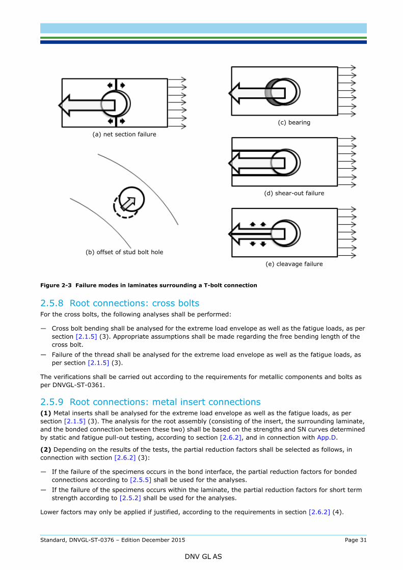
Figure 2-3 Failure modes in laminates surrounding a T-bolt connection
2.5.8 Root connections: cross boltsFor the cross bolts, the following analyses shall be performed:
— Cross bolt bending shall be analysed for the extreme load envelope as well as the fatigue loads, as per section [2.1.5] (3). Appropriate assumptions shall be made regarding the free bending length of the cross bolt.
— Failure of the thread shall be analysed for the extreme load envelope as well as the fatigue loads, as per section [2.1.5] (3).
The verifications shall be carried out according to the requirements for metallic components and bolts as per DNVGL-ST-0361.
2.5.9 Root connections: metal insert connections(1) Metal inserts shall be analysed for the extreme load envelope as well as the fatigue loads, as per section [2.1.5] (3). The analysis for the root assembly (consisting of the insert, the surrounding laminate, and the bonded connection between these two) shall be based on the strengths and SN curves determined by static and fatigue pull-out testing, according to section [2.6.2], and in connection with App.D.
(2) Depending on the results of the tests, the partial reduction factors shall be selected as follows, in connection with section [2.6.2] (3):
— If the failure of the specimens occurs in the bond interface, the partial reduction factors for bonded connections according to [2.5.5] shall be used for the analyses.
— If the failure of the specimens occurs within the laminate, the partial reduction factors for short term strength according to [2.5.2] shall be used for the analyses.
Lower factors may only be applied if justified, according to the requirements in section [2.6.2] (4).
(a) net section failure
(b) offset of stud bolt hole
(c) bearing
(d) shear-out failure
(e) cleavage failure
Standard, DNVGL-ST-0376 – Edition December 2015 Page 31
DNV GL AS
fatigue loads, as per section [2.1.5] (3). This verification shall be carried out according to the requirements for metallic components and bolts as per DNVGL-ST-0361.
2.5.10 Root connections: stud bolts(1) The stud bolts shall be analysed for the extreme load envelope as well as the fatigue loads, as per section [2.1.5] (3).
(2) The verifications shall be carried out according to the requirements for metallic components and bolts as per DNVGL-ST-0361.
(3) The characteristics of the root connection shall be specified (according to section [2.2.2]), and in particular the pre-tension, the tightening method, and the corrosion protection.
(4) If one part of the pre-stressed bolted connection is made of fibre-reinforced plastic (as it is the case in T-bolt connections), loss in pre-stressing of the bolted connection shall be considered, at least taking into account the following criteria:
— pre-stress loss due to short-term settling effects; in many cases, it may be required to check bolt pre-stressing shortly after installation (such as after 4 weeks, or after 200 hours of operation)
— pre-stress loss due to long-term volumetric shrinkage, or creep, of the fibre-reinforced plastic material.
(5) The stud bolt bending depending on the size of the external loads and also depending on the bearing configuration shall be considered in the analysis of the bolts. The relation between the external load and the stud bolt bending is usually non-linear, and shall be properly considered in the analyses.
2.5.11 Deflection and rotor clearance(1) It shall be ensured that the rotor blades dos not collide with the tower or other parts of the wind turbine.
(2) For this, a deformation analysis shall be performed for the relevant tower clearance load case (based on serviceability limit state loads) as per section [2.1.5] (3). The deformation analysis shall be performed by dynamic and aeroelastic means. The clearance shall not be less than 30% for the rotor turning, in relation to the clearance in the unloaded state.
(3) If the deformation analysis as per paragraph (2) above is supplemented by deflection measurements during full scale blade tests on at least 3 test blades of the same type design, the required minimum clearance shall be 25% for the rotor turning. Such deflection measurements shall be obtained at test bending loads that are at least as high as the tower clearance loads.
(4) If the deformation analysis as per paragraph (2) above and the deflection measurements as per paragraph (3) above are further supplemented by continuous control of the bending stiffness during series production of the rotor blades, the required minimum clearance shall be 20% for the rotor turning.
(5) If testing is performed according paragraph (3) and (4) above, the blade test rig stiffness shall be determined and compared to the turbine hub/pitch bearing assembly stiffness, in order to account for differences potentially influencing the measured deflection.
(6) In all cases, the clearance shall not be less than 5% for load cases with the rotor standing still, in relation to the clearance in the unloaded state.
(7) For offshore turbines, it shall be ensured that the rotor blades do not come in contact with the seawater during operation. Sufficient distance between the expected highest wave elevation and the lower edge of the rotor shall be kept. A clearance (air gap) of at least 1.5 m is recommended. In case of offshore wind turbines not connected rigidly to the sea floor (floating wind turbines), their vertical motions shall be accounted for.
2.5.12 Natural frequencies(1) Natural frequencies for the following vibration modes of the rotor blades shall be specified:
— first and second flapwise bending mode— first and second edgewise bending mode— first torsional mode.
Standard, DNVGL-ST-0376 – Edition December 2015 Page 32
DNV GL AS
elsewhere (e.g. as part of the wind turbine loads assumptions).
(3) The structural damping characteristics for the following vibration modes shall be estimated:
— first flapwise bending mode— first edgewise bending mode.
2.5.13 Inter-fibre failure(1) Inter-fibre failure (IFF) may lead to subsequent premature fibre failure (both static and fatigue), as well as premature buckling failure. In this context, the blade laminate (including sandwich face sheets) shall be verified for IFF, at all analysis locations as per section [2.5.1] (6), and taking into account local strains in all relevant directions (i.e. including transversal strains).
A suitable verification may consist of one or a combination of the following paragraphs (2), (3), and (4):
(2) Demonstration by analysis that IFF does not occur for the serviceability limit state loads envelope as per section [2.1.5] (3) for each individual layer of the laminate. Failures to be considered include IFF caused by in-plane transversal tensile or compressive stresses (σ2), by in-plane shear stresses (τ12), or a combination of these, and also influenced by in-plane longitudinal tensile or compressive stresses (σ1). For this, a suitable failure criterion shall be specified and applied, such as Puck [3], or Larc03 [4]. If one of these is taken as a basis for verification, the following coefficients shall be included, unless otherwise documented:
= 0.25
= 0.30
which are the inclination parameters according to Puck.
(3) Verification for fibre failure and buckling with design properties taking into account IFF pre-damage. This requires that all relevant material design values are established through test coupons that have been subjected to load-induced IFF cracking prior to ultimate or fatigue failure test. The material test programme shall at least include the following:
— UD and multiaxial fabrics ultimate tensile and compression with pre-damage induced by in-plane transversal tension and/or in-plane shear
— UD and multiaxial fabrics fatigue with pre-damage induced by in-plane transversal tension and/or in-plane shear.
The pre-loading shall at least be equivalent to the design ultimate strain for the relevant material and strain direction.
(4) Successful full-scale blade test according to Sec.4. This test shall include pre-fatigue static tests, fatigue tests, post-fatigue static tests, and measurement of natural frequencies before and after the test campaign. It shall be justified by analysis or other technical argumentation that areas with IFF being a potential failure mode are sufficiently loaded. Sufficient verification for IFF is obtained:
— if no IFF is observed in the blade structure after the fatigue test, proven by inspection under the surveillance of DNV GL; or
— if the post-fatigue static test results demonstrate that no deterioration of the structural behaviour of the blade has taken place despite the occurrence of IFF.
(5) The following partial reduction factors shall apply for verifications according paragraph (2) above:
Criticality of failure mode
γmc = 1.0 for all analyses
Long-term degradation
γm1 = 1.1 for all analyses
Temperature effects
γm2 = 1.0 for all analyses
┴║(−) ┴║(+)
Standard, DNVGL-ST-0376 – Edition December 2015 Page 33
DNV GL AS
γm3 = 1.0 for all analyses
Accuracy of analysis methods
γm4 = 1.15 for all analyses
Accuracy of load assumptions
(6) For this verification, it is acceptable to apply strength design values based on average values from material testing.
2.5.14 Special design featuresAppropriate design verification methods including analysis methods, factors, and testing shall be established by the designer (and agreed with DNV GL) for any special design features, such as:
— sectional joints— mechanisms— truss work— stiffeners— scarf joints— tip brakes— blade heaters for anti-ice / de-ice.
2.5.15 Additional failure modesIn general, it shall be evaluated whether the blade structure is critical with regard to failure modes not yet covered in this section [2.5]. If this is the case, appropriate design verification methods including analysis methods, factors, and testing shall be established by the designer (and agreed with DNV GL) for these failure modes, which can e.g. be:
— sandwich failure— impact— creep.
2.5.16 Metallic partsThe verifications for all metallic parts shall be carried out according to the requirements of DNVGL-ST-0361.
2.6 Intermediate level testing (sub-component testing)
2.6.1 Purpose of intermediate level testing and general requirements(1) In many cases, it may be appropriate or even necessary to supplement material coupon tests and full scale blade tests by further testing on an intermediate level. When certifying a rotor blade for compliance with the present standard, such intermediate level testing may be applied for the following purposes:
— as part of the design verification process, by using test results as design values in structural verification analyses (section [2.6.2])
— as partial substitute for full scale blade testing (section [2.6.3]).
Guidance note:Usually, validation and testing of a rotor blade design is primarily based on two types of tests: material coupon tests on the one hand, and full scale blade tests on the other hand. In a validation and testing concept often referred to as the “building block approach”, these two types of tests can be considered as the lowest and the highest level of a test pyramid as shown in Figure 2-4.
γm5 = 1.0 if loads in at least 12 directions according to section [2.1.5] (4) are applied1.1 if the analysis is carried out in only 4 main directions according to section [2.1.5] (5)
Standard, DNVGL-ST-0376 – Edition December 2015 Page 34
DNV GL AS
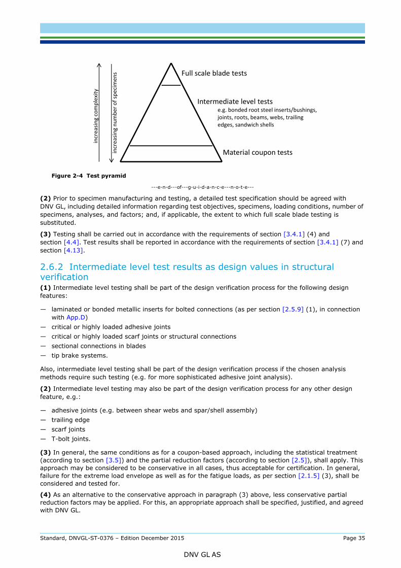
Figure 2-4 Test pyramid
---e-n-d---of---g-u-i-d-a-n-c-e---n-o-t-e---
(2) Prior to specimen manufacturing and testing, a detailed test specification should be agreed with DNV GL, including detailed information regarding test objectives, specimens, loading conditions, number of specimens, analyses, and factors; and, if applicable, the extent to which full scale blade testing is substituted.
(3) Testing shall be carried out in accordance with the requirements of section [3.4.1] (4) and section [4.4]. Test results shall be reported in accordance with the requirements of section [3.4.1] (7) and section [4.13].
2.6.2 Intermediate level test results as design values in structural verification(1) Intermediate level testing shall be part of the design verification process for the following design features:
— laminated or bonded metallic inserts for bolted connections (as per section [2.5.9] (1), in connection with App.D)
— critical or highly loaded adhesive joints— critical or highly loaded scarf joints or structural connections— sectional connections in blades— tip brake systems.
Also, intermediate level testing shall be part of the design verification process if the chosen analysis methods require such testing (e.g. for more sophisticated adhesive joint analysis).
(2) Intermediate level testing may also be part of the design verification process for any other design feature, e.g.:
— adhesive joints (e.g. between shear webs and spar/shell assembly)— trailing edge— scarf joints— T-bolt joints.
(3) In general, the same conditions as for a coupon-based approach, including the statistical treatment (according to section [3.5]) and the partial reduction factors (according to section [2.5]), shall apply. This approach may be considered to be conservative in all cases, thus acceptable for certification. In general, failure for the extreme load envelope as well as for the fatigue loads, as per section [2.1.5] (3), shall be considered and tested for.
(4) As an alternative to the conservative approach in paragraph (3) above, less conservative partial reduction factors may be applied. For this, an appropriate approach shall be specified, justified, and agreed with DNV GL.
Full scale blade tests
Material coupon tests
Intermediate level testse.g. bonded root steel inserts/bushings, joints, roots, beams, webs, trailing edges, sandwich shells
incr
easin
g co
mpl
exity
incr
easin
g nu
mbe
r of s
peci
men
s
Standard, DNVGL-ST-0376 – Edition December 2015 Page 35
DNV GL AS
For example, for intermediate level testing including manufacturing tolerance effects, the partial reduction factors may be adjusted accordingly.
As a rule of thumb, the more representative the intermediate level test specimens are with respect to the criteria in paragraph (4), or in other words the further up they can be located in the test pyramid of Figure 2-4, the smaller the partial reduction factors may be. When applying this principle, a proper methodology shall be defined, and agreed with DNV GL beforehand.
---e-n-d---of---g-u-i-d-a-n-c-e---n-o-t-e---
2.6.3 Intermediate level testing for supplementing full scale blade testing(1) Intermediate level testing on a given area (or design feature) of the blade may be accepted as a substitute for full scale blade testing (see section 4) in the following cases:
— the regarded area is affected by a design modification, while the rest of the previously certified blade remains unchanged (applies also for blade variants)
— the regarded area has not been or cannot be sufficiently loaded during full scale blade testing— the regarded area has suffered structural damage during full scale blade testing, thus requiring further
testing.
In addition, intermediate level testing may be used to supplement full scale blade testing in order to improve the understanding of critically loaded blade sub-components.
Guidance note:In some situations, intermediate level testing may even be capable of replicating real design loading and constraint conditions more accurately than full scale testing, and thus e.g. serve as a basis for test-correlated analysis.
---e-n-d---of---g-u-i-d-a-n-c-e---n-o-t-e---
(2) Such intermediate level testing shall be carried out under the conditions (including the test load factors) stipulated in section 4, provided the following conditions are fulfilled:
— The test specimens shall be representative of the actual blade in terms of materials, structural design, manufacturing processes and quality control.
— The specimens shall be built to a geometrical scale of 1:1, unless justification as per section [2.6.6] (2) is provided.
— The size of specimens shall be chosen such that the boundaries do not interfere with the structural response of the area (or design feature) under investigation.
— The test loads shall be defined such that the local loading conditions of the area (or design feature) under investigation are equivalent to the actual blade structure.
(3) If any of the conditions of paragraph (2) above are not fulfilled (or their fulfilment cannot be readily demonstrated), the test load factors shall be increased in order to account for the increased level of uncertainty resulting from this non-fulfilment. The magnitude of the factors shall be established based on analyses in connection with the requirements in section [2.6.4] through to [2.6.6].
(4) Test factors shall be agreed with DNV GL prior to testing.
Guidance note:As a rule of thumb, the less representative the intermediate level test specimens are with respect to the criteria in paragraph (2), or in other words the further down they have to be located in the test pyramid of Figure 2-4, the larger the test load factors should be. When applying this principle, a proper methodology should be defined, and agreed with DNV GL beforehand.
---e-n-d---of---g-u-i-d-a-n-c-e---n-o-t-e---
2.6.4 Requirements for test specimens(1) It shall be shown to which extent a test specimen is representative of the actual blade design, materials, and manufacturing. For this, the test specimen shall be fully specified, and test specimen manufacturing shall be fully controlled and documented, including:
— drawings of the structural design of the specimen— material specifications— generic process specifications (for laminating, bonding, surface preparation, etc.)
Standard, DNVGL-ST-0376 – Edition December 2015 Page 36
DNV GL AS
— manufacturing equipment (such as moulds)
— manufacturing and quality control records.
(2) It may be required by DNV GL to inspect and witness specimen manufacturing.
2.6.5 Test loads and boundary conditions(1) Test loads shall be defined such that the local loading conditions in the area to be tested are representative of the actual blade structure, in terms of magnitude, directions, and resulting failure modes. Loading based on the extreme load envelope as well as on the fatigue loads, as per section [2.1.5] (3), shall be considered.
(2) Intermediate level testing may be applied as part of the design verification process in various ways, such as:
— testing to failure in order to generate design values (based on ultimate strengths, and SN curves)
— demonstrating a high margin to the design load
— for model calibration.
(3) If the intermediate level testing is applied as partial substitute for full scale blade testing, the test loads shall be defined in compliance with the requirements in Sec.4.
(4) Test specimens, local reinforcements, and test rigs shall be designed in a way that the resulting boundary conditions for load introduction accurately reproduce the conditions in the actual blade structure.
2.6.6 Accompanying analyses(1) Intermediate testing should be accompanied by structural analysis (such as FEA or analytical methods), in order to establish correspondence between test specimen and blade structure.
Guidance note:Such analyses should include a model of the test specimen and a model of the actual blade structure in the regarded area (or design feature). These two models should be based on the same methods and the same modelling parameters (such as FEA element types and size, and numerical settings).
With these models, the following comparisons should be made:
— predictions from the specimen model compared to the intermediate level test results (such as strain readings)
— predictions from the actual blade model compared to full scale blade test results
— predictions from the specimen model compared to predictions from the actual blade model.
---e-n-d---of---g-u-i-d-a-n-c-e---n-o-t-e---
(2) If a test specimen is not built to a scale of 1:1, the effects of scaling shall be evaluated, and taken into account when defining test load factors, in particular with regard to the following aspect:
— local effects of dimensions which cannot be accurately scaled, e.g. individual material ply thicknesses, bond line thicknesses, or fibre diameters
— changes in local material properties or in residual stresses due to changes in dimensions, e.g. resulting from different temperature conditions during cure
— influence of scaling on boundary conditions for load introduction
— scaled magnitude of test loads
(3) The sub-component model should show and confirm the correlation of stress/strain response between blade model, intermediate level model, test results from intermediate level testing, and test results from full scale blade testing.
(4) Such comparisons may be the basis for demonstrating correspondence between test specimen and blade structure, and may assist in defining (or re-defining) test load factors.
Standard, DNVGL-ST-0376 – Edition December 2015 Page 37
DNV GL AS
3.1 General(1) All structural materials used in the blade shall be described and documented in material specifications, in a way that they are clearly identifiable and traceable. In this context, structural materials are all materials which determine, or have a direct effect on, the mechanical strength and the structural behaviour of the blade.
(2) For all structural materials used in the blade, a set of structural design values shall be established and documented as part of the design documentation.
(3) For all structural materials used in the blade, material qualification requirements shall be specified.
(4) As part of a blade design, at least one specific individual product for each material used in the blade shall be qualified.
3.2 Specifications and qualification requirements
3.2.1 Material specifications and qualification requirements(1) Material specifications have the purpose of:
— providing unambiguous material designations for reference in design drawings— serving as a reference for design analyses— serving as a reference for manufacturing documentation and quality control.
(2) Material specifications shall at least include:
— material designation— unique identification codes for reference in design and manufacturing (e.g. in drawings)— physical, chemical and mechanical material properties as per section [3.3].
(3) Material qualification for a specific individual product has the purpose of:
— demonstrating compliance with the material requirements that are specified as per section [3.3]— ensuring that the design values assumed for analysis (as per section [3.4.1]) are consistent with the
actual material properties— ensuring that the material is suitable for the specific manufacturing process used in blade production
and for the use in combination with the other materials.
(4) Material qualification requirements shall at least include:
— requirements for traceability of materials (e.g. name and trademark of manufacturer, material grade, batch number)
— requirements for repeatability of manufacturing processes (e.g. curing control for resins and adhesives)— requirements for material storage (e.g. control of temperature, humidity and shelf life)— characteristic structural material properties for all relevant limit states, under consideration of minimum
and maximum service temperatures, and other environmental conditions— qualification schemes for specific individual products; the schemes shall identify required means of
compliance (e.g. test methods) used to document material compatibility with existing approved materials, as well as the material’s characteristic structural material properties
— qualification records for the suppliers.
(5) Conditions for material purchase shall be specified, either as part of the material specifications, or as separate material purchase specifications. These shall as a minimum cover: incoming material inspection requirements (physical, chemical and mechanical testing, test standards, test frequency), batch size, certificate of conformity, marking (labels/colour codes).
Standard, DNVGL-ST-0376 – Edition December 2015 Page 38
DNV GL AS
(1) For all processes involving polymeric materials, the manufacturing processes to be applied in connection with each material shall be reported in a generic process description.
(2) For fibre-reinforced plastics, these shall at least include:
— type of processing (hand lay-up, infusion, pultrusion, prepreg, or others)— principle of vacuum set-up and level of applied differential pressure— most relevant processing temperature profiles, at least including application temperature and time, and
cure temperature and time (or a definition of a minimum required degree of curing to be achieved by the curing process for each resin system, e.g. in terms of a minimum Tg)
— target fibre volume content.
(3) For adhesive joints, these shall at least include:
— type of processing (co-curing, co-bonding, adhesive bonding, or others)— maximum and minimum thickness of adhesive joint— most relevant surface preparation parameters (peel-ply, grinding, protection, open time)— most relevant processing temperature profiles, at least including application temperature and time, and
cure temperature and time (or a definition of a minimum required degree of curing to be achieved by the curing process for each resin system, e.g. in terms of a minimum Tg).
3.3 Material requirements
3.3.1 General(1) All materials shall be described by engineering parameters in a suitable way, enabling their behaviour to be predetermined under all relevant design loads and other critical actions during the operational lifetime of the rotor blade.
(2) For the following materials commonly used in state-of-the-art blade designs, the requirements provided in the remainder of this section [3.3] may generally be considered sufficient to satisfy the fundamental requirement stated in paragraph (1) above:
— fibre-reinforced plastics (FRP) made from glass or carbon fibres, and epoxy or polyester resins and adhesives
— wooden or polymeric sandwich core materials— metals.
For other materials (such as laminated ply wood, bamboo, natural fibres, vinyl ester resins, and other types of adhesive chemistries), the designer shall specify appropriate requirements, if possible along the lines of this section [3.3].
(3) All material requirements shall be specified in connection with the manufacturing process to be used in the blade production. In this context, specific reference to the manufacturing processes described as per section [3.2.2] shall be made.
(4) Each of the characteristics listed in the remainder of this section [3.3] shall be specified together with appropriate tolerances.
(5) In general, all materials used in rotor blades shall fulfil the requirements for DNV GL material approval (according to the references in Table 1-2).
3.3.2 Fibre reinforcements(1) The following characteristics shall be specified for reinforcement fibres:
— fibre material (such as E-glass, H-glass, PAN-based carbon, pitch-based carbon)— sizing— density
Standard, DNVGL-ST-0376 – Edition December 2015 Page 39
DNV GL AS
— roving filament count and twist— E modulus— tensile strength.
(2) The following characteristics shall be specified for fibre reinforcement semi-finished products (textiles):
— type of textile (woven fabric, woven UD, non-crimp fabric)— weave type— stitching characteristics (e.g. type, yarn, tension, stitch density)— construction (individual ply areal mass and orientation, stacking sequence).
3.3.3 Resin matrices(1) The following characteristics shall be specified for resin matrices:
— resin chemistry type— nominal mixing ratio— application methods— density (in cured state)— thermal stability (e.g. glass transition temperature)— strain to failure.
(2) Thermal stability of the matrix resin shall be proven with regard to the blade temperature range, as per section [2.1.2] (2), for which the rotor blade is designed. If the glass transition temperature (Tg) exceeds θmax,blade by at least 15°C, no further proof regarding thermal stability is required.
3.3.4 Pre-impregnated semi-finished products(1) The following characteristics shall be specified for prepregs:
— resin content prior to curing— tackiness as appropriate— target cured ply thickness.
(2) The following characteristics shall be specified for semi-cured or cured semi-finished products (e.g. pultruded semi-finished products):
— fibre volume content— dimensions (thickness, width, end chamfer geometry).
3.3.5 Fibre-reinforced plastic (FRP) laminates(1) The following physical properties shall be specified for each finished FRP laminate made from the constituent materials specified as per sections [3.3.2], [3.3.3], and [3.3.4]:
— laminate thickness— average density— fibre volume content— degree of cure (with regard to a fully cured laminate), e.g. as residual enthalpy.
(2) The following elastic properties shall be specified for these FRP laminates:
— most relevant engineering constants, i.e. E11, E22, G12, and ν12— assumptions regarding the remaining engineering constants to specify full orthotropic elastic properties.
Any non-linearity in material behaviour shall be properly described, and any simplification (linearization) applied to these shall be shown to be appropriate.
Standard, DNVGL-ST-0376 – Edition December 2015 Page 40
DNV GL AS
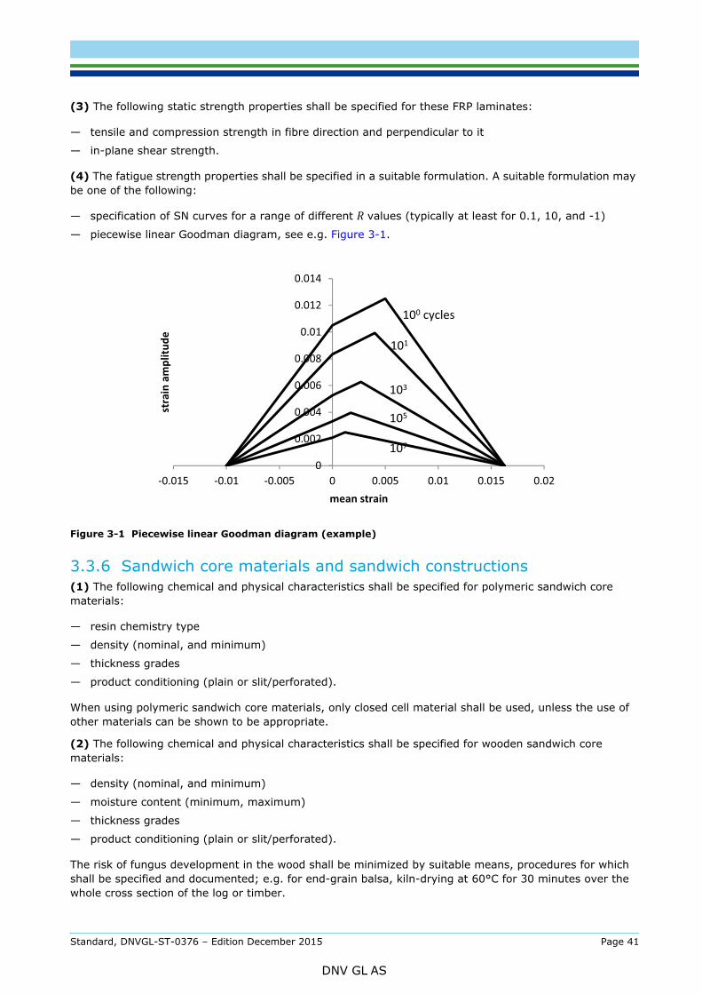
— tensile and compression strength in fibre direction and perpendicular to it
— in-plane shear strength.
(4) The fatigue strength properties shall be specified in a suitable formulation. A suitable formulation may be one of the following:
— specification of SN curves for a range of different R values (typically at least for 0.1, 10, and -1)
— piecewise linear Goodman diagram, see e.g. Figure 3-1.
Figure 3-1 Piecewise linear Goodman diagram (example)
3.3.6 Sandwich core materials and sandwich constructions(1) The following chemical and physical characteristics shall be specified for polymeric sandwich core materials:
— resin chemistry type
— density (nominal, and minimum)
— thickness grades
— product conditioning (plain or slit/perforated).
When using polymeric sandwich core materials, only closed cell material shall be used, unless the use of other materials can be shown to be appropriate.
(2) The following chemical and physical characteristics shall be specified for wooden sandwich core materials:
— density (nominal, and minimum)
— moisture content (minimum, maximum)
— thickness grades
— product conditioning (plain or slit/perforated).
The risk of fungus development in the wood shall be minimized by suitable means, procedures for which shall be specified and documented; e.g. for end-grain balsa, kiln-drying at 60°C for 30 minutes over the whole cross section of the log or timber.
0
0.002
0.004
0.006
0.008
0.01
0.012
0.014
-0.015 -0.01 -0.005 0 0.005 0.01 0.015 0.02
stra
in a
mpl
itude
mean strain
100 cycles
101
103
105
107
Standard, DNVGL-ST-0376 – Edition December 2015 Page 41
DNV GL AS
— most relevant engineering constants, i.e. G13, G23, and E33— assumptions regarding the remaining engineering constants to specify full elastic properties— tensile and compression strength, both in-plane and out-of-plane— shear strength, both in-plane and out-of-plane.
(4) It shall be specified which core materials are to be combined with which face sheet materials and in which processing technology, to form a sandwich construction. For all sandwich constructions, the following properties shall be specified:
— effective core material density— effective core material out-of-plane shear modulus G13 and G23— effective core material out-of-plane shear strength— effective out-of-plane elastic Young’s modulus E33.These effective properties shall take into account all effects resulting from the manufacturing process by which the sandwich construction is built up, such as resin up-take of porous and slit or perforated materials.
(5) All sandwich core materials shall be capable of sustaining the highest temperatures to be expected during manufacturing and operation without suffering deterioration of their structural properties.
3.3.7 Adhesives(1) The following chemical and physical characteristics shall be specified for adhesives:
— resin chemistry type— nominal mixing ratio— density (in cured state)— type and amount of thixotropic agent, if applicable— thermal stability, e.g. glass transition temperature— degree of cure (with regard to a fully cured joint), e.g. as residual enthalpy.
(2) Thermal stability of the matrix resin shall be proven with regard to the blade temperature range, as per section [2.1.2] (2), for which the rotor blade is designed. If the glass transition temperature (Tg) exceeds θmax,blade by at least 15°C, no further proof regarding thermal stability is required.
(3) The following elastic properties shall be specified for adhesives:
— engineering constants, i.e. Young’s modulus E, shear modulus G, and Poisson’s ratio ν12.(4) The following strength properties shall be specified for adhesives:
— neat resin ultimate tensile and ultimate compressive strength— ultimate and fatigue adhesive joint strength (appropriately considering shear and peel)— fracture toughness of the adhesive joint (mode I, mode II, and mixed mode), if used as basis for design
verification analyses.
(5) The fatigue strength or crack resistance properties shall be specified in a suitable way.
(6) For all bonded connections, the compatibility between adhesive and the adherent materials shall be ensured (e.g. by testing).
3.3.8 Surface finish materials and sealants(1) In general, it shall be demonstrated that all surface finish materials (such as paints, coatings, primers, fillers), and all sealants used for protecting metallic parts or sandwich core material edges, are suitable for the intended purpose. Such materials should have the following characteristics:
— high elasticity, i.e. capability to sustain all mechanical strains of the blade structure, as well as rain impact
Standard, DNVGL-ST-0376 – Edition December 2015 Page 42
DNV GL AS
— good resistance against UV radiation and against ageing in marine, tropical and industrial environments— sufficient compatibility and adhesion to substrate materials, and good ablation resistance— good adhesion strength between the applied layers.
(2) It shall be demonstrated that surface finish materials used for the leading edge and the tip have sufficient resistance against rain erosion, e.g. in a rain erosion or “helicopter” test. Abrasion by other abrasive particles (such as hail, dust, sand, salt) should also be considered. If the investigation shows that the life time of the leading edge coating is less than the lifetime of the blade, suitable inspection and maintenance intervals shall be specified.
(3) The protection of metallic parts shall comply with the requirements of DNVGL-ST-0361.
3.3.9 MetalsMetallic materials used in the blade shall fulfil the requirements specified in DNVGL-ST-0361.
3.3.10 Resistance of structural materials against environmental influences(1) Certain partial reduction factors specified in section [2.5] are intended to account for degradation of material properties due to environmental influences. Still, the designer shall ensure and demonstrate that all materials used in the blade structure have sufficient durability and resistance against all environmental influences that are expected to be encountered during operation.
(2) Such demonstration may require additional material testing.
3.4 Material qualification and testing
3.4.1 General(1) For the qualification of a specific individual product, compliance with the applicable material requirements as per section [3.2.2] shall be demonstrated.
(2) This demonstration of compliance shall be based on
— material qualification testing; or— material characteristics guaranteed by the material supplier.
(3) For certification, material qualification testing shall be mandatory for all characteristics listed in this section [3.4]. For all other characteristics of section [3.2.2], compliance through guaranteed material characteristics is sufficient.
(4) All tests shall be carried out by laboratories which are accredited for the relevant test methods according ISO 17025. In the absence of such accreditation, the capabilities of the test laboratory and the validity of the test results shall be verified by DNV GL as follows:
— verification of compliance with the criteria of ISO 17025, as applicable; and— test witnessing by DNV GL.
The detailed scope of verification and witnessing shall be agreed with DNV GL.
Guidance note:In this context, verification for ISO 17025 and witnessing may be combined to various degrees, for example:
Variant 1:
— verification of compliance with the criteria of ISO 17025— witnessing of sample tests on a regular basis— resulting in a DNV GL laboratory acknowledgement, which will allow the test laboratory to carry out tests for certification during
the period between the sample test witnessing.
Variant 2:
— extensive witnessing for the relevant test methods— verification of compliance with those criteria of ISO 17025 that are most relevant to ensure that the parts of the test that are
not witnessed are valid.
Standard, DNVGL-ST-0376 – Edition December 2015 Page 43
DNV GL AS

— full test witnessing— verification of compliance with the most essential criteria of ISO 17025:
— equipment: traceability of tested items, sensors and equipment; calibration and accuracy of sensors; data recording and data processing
— personnel: training and responsibilities of the individuals participating in the test— reporting: accuracy, clarity and unambiguousness of reporting; measurement uncertainties.
---e-n-d---of---g-u-i-d-a-n-c-e---n-o-t-e---
(5) Compliance with the requirements of section [3.3.1] (3) shall be documented, i.e. it shall be shown as part of the material test documentation that each test specimen is manufactured in a process that is sufficiently similar to the blade manufacturing process.
(6) The validity of qualification testing shall be verified in regular intervals (in general not exceeding four years).
(7) All test results shall be documented in a test report in compliance with the general requirements of ISO 17025, in compliance with any specific requirements of the applied test standards, and in any case containing at least the following:
— date and place of specimen manufacture— identity of each material used, including supplier data sheet, and batch number— lay-up of test specimens— specimen manufacturing process— identity and designation of individual test specimens— dimensions of each individual test specimen— date and place of tests— description of test equipment— applied test methods and standards— testing conditions, including temperature and humidity— fibre content normalisation method— test results for each individual test specimen (both normalised and not normalised), including all
recorded data, and in particular all stress (or load) and strain (or displacement) readings— description of failure mode of each tested specimen— photos of each tested specimen.
(8) For each type of test, a suitable test method shall be selected. See App.A for an overview of generally acceptable material test methods and standards.
(9) In general, all testing may be carried out in normal climatic conditions (i.e. at room temperature and moderate humidity, such as 23/50 as defined in ISO 291), unless testing in different climatic conditions is specifically required.
Guidance note:E.g., testing in different climatic conditions may be required in connection with operation in extreme environments (see section [2.1.2]), or in connection with a specific selection of partial reduction factors (see section [2.5]).
---e-n-d---of---g-u-i-d-a-n-c-e---n-o-t-e---
3.4.2 Resin matrices(1) The following shall be demonstrated through material qualification testing for resin matrices:
— thermal stability (e.g. glass transition temperature).
3.4.3 Fibre-reinforced plastic (FRP) laminate testing(1) The following static strength and elastic properties shall be demonstrated through material qualification testing of an FRP laminate for each type of reinforcement (e.g. each fabric or prepreg type) made from the constituent materials specified as per sections [3.3.2], [3.3.3], and [3.3.4]:
— tensile strength, tensile modulus, and Poisson’s ratio in main fibre direction
Standard, DNVGL-ST-0376 – Edition December 2015 Page 44
DNV GL AS

— tensile strength and tensile modulus perpendicular to the main fibre direction
— compression strength and compression modulus perpendicular to the main fibre direction
— in-plane shear strength and shear modulus.
Guidance note:In this context, the “main fibre direction” designates the direction in which most of the fibres are oriented, e.g.:
— Unidirectional fabric with almost all fibres in 0° direction: testing in main fibre direction means testing in 0° direction.
— Unidirectional fabric with almost all fibres in 90° direction: testing in main fibre direction means testing in 90° direction.
— Biaxial fabric with 50% fibres in +45° direction, and 50% fibres in –45° direction: testing in main fibre direction means testing in +45° direction (testing in –45° direction may then be omitted if the material is of a symmetrical construction).
— Triaxial material, e.g. mainly 0° plus ±45°: testing in main fibre direction means testing in 0° direction (testing in ±45° direction may then be omitted because not feasible).
Testing for strength perpendicular to the main fibre direction is generally only meaningful when applied to unidirectional fabrics (i.e. with a maximum fibre weight of 5% parallel to the test direction); if other materials are tested, the test configuration should be agreed with DNV GL prior to testing.
Testing for shear strength is generally only meaningful when applied to unidirectional fabrics or to biaxial fabrics with a 0°/90° or +45°/–45° construction.
---e-n-d---of---g-u-i-d-a-n-c-e---n-o-t-e---
(2) Fatigue strength properties shall be demonstrated through material qualification testing of an FRP laminate for each type of reinforcement (e.g. each fabric or prepreg type) made from the constituent materials specified as per sections [3.3.2], [3.3.3], and [3.3.4].
(3) Fatigue testing shall be carried out at R = –1, and also at additional R values if specified as per section [3.3.5] (4) and if required in connection with a particular selection of partial reduction factors as per section [2.5.3]. If justified in particular design configurations, testing at R = –1 may be omitted, and replaced by testing at an R value based on the most conservative failure mode (e.g. wrinkle tests at R = 10, scarf joints or ply drops at R = 0.1).
(4) For each R value, fatigue testing shall comprise at least 12 specimens, spread over a sufficient range of cycle numbers, containing 4 consecutive decades with 3 specimens in each decade, and including the decade between 106 to 107 cycles.
Guidance note:For example, the following will comply with these requirements:
— 3 specimens tested to a cycle number to failure between 103 to 104
— 3 specimens tested to a cycle number to failure between 104 to 105
— 3 specimens tested to a cycle number to failure between 105 to 106
— 3 specimens tested to a cycle number to failure between 106 to 107
(with at least 1 specimen failing at the order of 107 cycles, or a run-out at 107 cycles which can be included in the statistical evaluation).
---e-n-d---of---g-u-i-d-a-n-c-e---n-o-t-e---
(5) In consideration of the requirements of section [3.3.1] (3), the following characteristics shall be measured and documented for each of the laminates from which the test coupons are retrieved:
— principle processing method
— processing route (in particular temperature, differential pressure, duration of each processing step)
— resin mixing ratio
— fibre volume content.
In general, the fibre volume content of the test laminates shall not deviate from the average fibre volume content specified for the blade design and manufacturing by more than 2.5 percentage points. A wider variation (up to a maximum of 5 percentage points) may be acceptable if normalization according to section [3.5.2] is applied.
Standard, DNVGL-ST-0376 – Edition December 2015 Page 45
DNV GL AS
(1) The following properties shall be demonstrated through material qualification testing for each sandwich construction as per section [3.3.6] (4):
— effective core material out-of-plane shear modulus— effective core material out-of-plane shear strength.
(2) For core materials other than PVC and balsa, sufficient adhesion to the face sheets shall be proven by testing.
(3) For core materials other than PVC and balsa, sufficient resistance to fatigue loading shall be proven by testing.
(4) In consideration of the requirements of section [3.3.1] (3), the following shall be documented for each of the sandwich laminates from which the test coupons are retrieved:
— principle processing method— processing route (in particular temperature, differential pressure, duration of each processing step)— core material conditions (slit or perforated).
(5) The material used for the sandwich face sheets shall be representative for the material used in the blade design.
Guidance note:For example, the following lay-up may be suitable:
— core thickness of approx. 25 mm— face sheet thickness of approx. 2.5 mm on either side— quasi-isotropic (0°/90°/+45°/–45°) face sheet lay-up.
---e-n-d---of---g-u-i-d-a-n-c-e---n-o-t-e---
(6) The actual density and thickness of the core material used in the tested sandwich shall be measured and reported.
3.4.5 Adhesive joints testing(1) The following physical properties shall be demonstrated through material qualification testing for each adhesive resin:
— thermal stability (e.g. glass transition temperature).
(2) The following mechanical properties shall be demonstrated through material qualification testing for each adhesive resin:
— ultimate and fatigue adhesive joint strength (appropriately considering shear; peel, and axial stresses)— fracture toughness (mode I, mode II, and mixed mode), if used as basis for design verification analyses.
(3) If the design verification of an adhesive joint against creep (see section [2.5.5] (5)) is based on material creep limits, material qualification testing of the adhesives shall include appropriate creep tests (see [A.5.5]).
(4) In consideration of the requirements of section [3.3.1] (3), the following shall be documented for each of the adhesive joint specimens from which the test coupons are retrieved:
— substrate materials— principle processing method— mixing ratio— type and amount of thixotropic agent, if applicable— adherents’ surface preparation and open time before adhesive application— processing route (in particular temperature, time before closing, joining pressure, post-cure)— shape of bond line fillet, if applicable
Standard, DNVGL-ST-0376 – Edition December 2015 Page 46
DNV GL AS
— post-bond inspection (visual).
In general, the bond line thickness of the test specimens should be selected in accordance with the maximum bond line thickness specified for the blade design and manufacture, in particular in connection with intermediate level testing (according to section [2.6]).
(5) For all static adhesive material qualification tests, a minimum of two adhesives batches should be used to manufacture the test joint pieces.
3.4.6 Surface finish materials and sealantsSurface finish materials used for the leading edge and the tip should fulfil the requirements specified in DNVGL-CP-0424. In addition, the most disadvantageous boundary conditions such as repairs and common production tolerances shall be taken into account for the validation of the leading edge protection.
3.5 Design values(1) The following data shall be reported and specified for each of the tested material properties, based on the test results:
— derivation of mean (i.e. average) value— derivation of characteristic value by applying statistical methods (see sections [3.5.1], [3.5.2],
and [3.5.3])— specification of value used in design (see section [3.5.4], and [3.5.5]).
(2) Each set of test results shall be investigated for outliers. An outlier is an observation that is much higher or much lower than most other observations in a data set, e.g. due to a defective test specimen [1]. Those values for which a cause can be determined should be corrected if possible, and otherwise discarded. When errors in data collection or recording are discovered, all data should be examined to determine whether similar errors occurred; these values should also be corrected or discarded. If an outlier is clearly erroneous, it can be removed after careful consideration provided that the subjective decision to remove a value is documented as part of the data analysis.
(3) If no cause can be found for an outlier, it shall be retained in the data set.
3.5.1 Derivation of characteristic material values(1) Characteristic strength values for polymeric materials (including adhesives and fibre-reinforced polymers) shall be derived from test results as the lower limit of the population’s 5th percentile with a 95% confidence. The 5th percentile corresponds to a value below which only 5% of the population is expected to lie.
(2) For each set test results, containing a number n of individual results, the following statistical parameter shall be determined:
where:
xi the i-th individual test resultn number of specimen test results in the sample
sample means2 sample variance.
= 1
2 = 1− 1 ( − )2
Standard, DNVGL-ST-0376 – Edition December 2015 Page 47
DNV GL AS
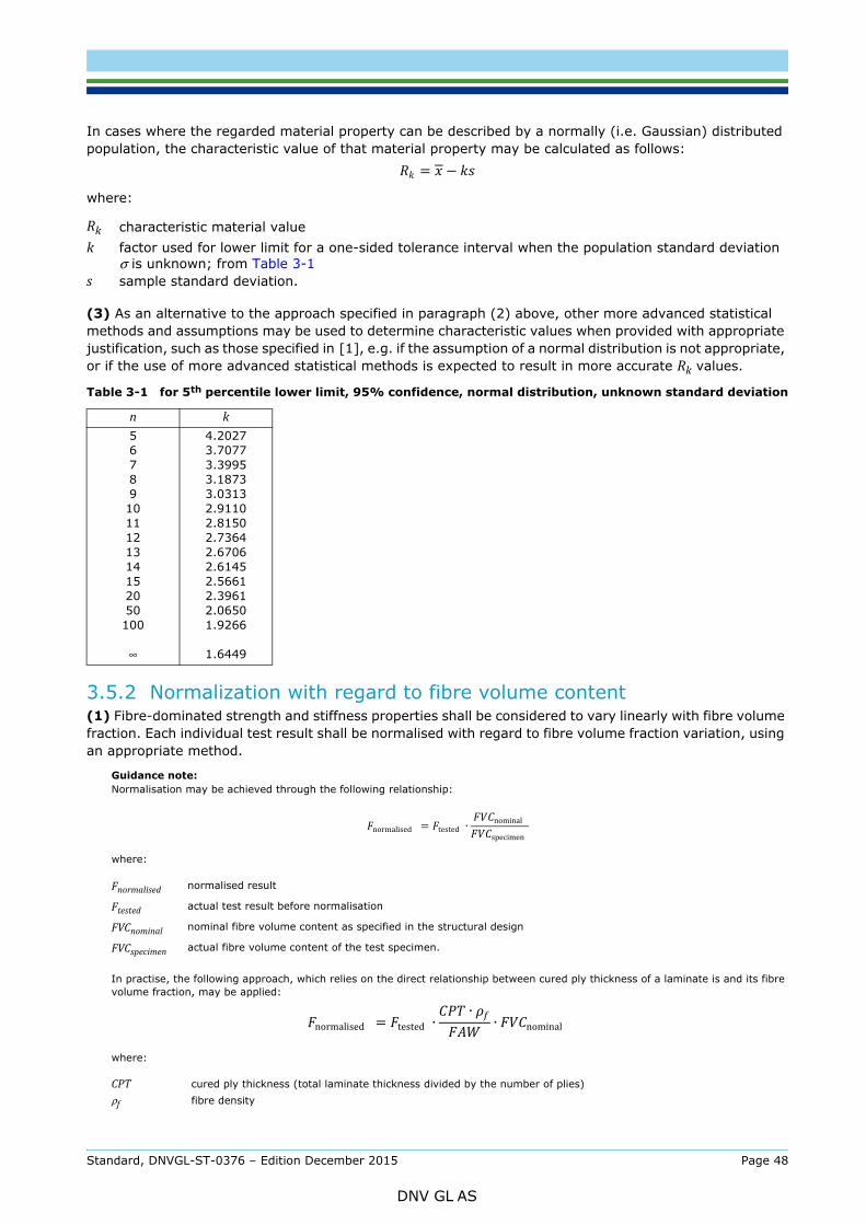
population, the characteristic value of that material property may be calculated as follows:
where:
(3) As an alternative to the approach specified in paragraph (2) above, other more advanced statistical methods and assumptions may be used to determine characteristic values when provided with appropriate justification, such as those specified in [1], e.g. if the assumption of a normal distribution is not appropriate, or if the use of more advanced statistical methods is expected to result in more accurate Rk values.
3.5.2 Normalization with regard to fibre volume content(1) Fibre-dominated strength and stiffness properties shall be considered to vary linearly with fibre volume fraction. Each individual test result shall be normalised with regard to fibre volume fraction variation, using an appropriate method.
Guidance note:Normalisation may be achieved through the following relationship:
where:
In practise, the following approach, which relies on the direct relationship between cured ply thickness of a laminate is and its fibre volume fraction, may be applied:
where:
Rk characteristic material valuek factor used for lower limit for a one-sided tolerance interval when the population standard deviation
σ is unknown; from Table 3-1 s sample standard deviation.
Table 3-1 for 5th percentile lower limit, 95% confidence, normal distribution, unknown standard deviation
n k567891011121314152050100
∞
4.20273.70773.39953.18733.03132.91102.81502.73642.67062.61452.56612.39612.06501.9266
1.6449
Fnormalised normalised result
Ftested actual test result before normalisation
FVCnominal nominal fibre volume content as specified in the structural design
FVCspecimen actual fibre volume content of the test specimen.
CPT cured ply thickness (total laminate thickness divided by the number of plies)ρf fibre density
= −
normalised = tested ∙ nominalspecimen
normalised = tested ∙ ∙ ∙ nominal
Standard, DNVGL-ST-0376 – Edition December 2015 Page 48
DNV GL AS
---e-n-d---of---g-u-i-d-a-n-c-e---n-o-t-e---
(2) Test results on not fibre-dominated properties (such as Poisson’s ratio, 90º axis, and in-plane / inter-laminar shear characteristics) shall not be normalised.
3.5.3 Fatigue tests(1) For fatigue test results, a statistical treatment equivalent to the one described above shall be applied. For this, at least the following shall be reported for each fatigue test series:
— test results in the form of an SN curve— linear (or piecewise linear, if applicable) regression in a logarithmic- logarithmic representation,
resulting in the SN curve above which 50% of the population is expected to lie— slope m of the SN curve— statistical treatment to obtain the SN curve below which only 5% of the population is expected to lie
with a 95% confidence.
3.5.4 Design values derived from testing(1) For each material strength property relevant for structural design, a design value Rd to be applied in the design analyses shall specified. It shall be demonstrated that the characteristic value Rk obtained as per section [3.5.1] is equal or greater than the specified design value:
(2) In deviation from the requirement in paragraph (1) above, the design value may be based on the mean value of the test results (instead of the characteristic value) if admitted with regard to a specific failure mode verification (i.e. inter-fibre failure as per section [2.5.13]).
(3) For each elastic property, the design value shall be established based on the mean value obtained from testing (without statistical treatment), within a specified tolerance.
Guidance note:For the most relevant elastic properties (in particular the modulus in fibre direction), a tolerance of±5% may be acceptable without further justification, provided that the tower clearance verification as per section [2.5.11] is based on the lower boundary of this tolerance.
---e-n-d---of---g-u-i-d-a-n-c-e---n-o-t-e---
(4) All material design values shall be specified in connection with the nominal fibre volume content and the nominal ply thickness. For each one, it shall be specified whether normalization according to section [3.5.2] has been applied in the process of establishing the design value.
(5) Design values for properties that are less relevant for the structural design (i.e. all properties for which testing is not explicitly required in section [3.4]) may be established based on engineering considerations.
(6) Design values for materials that are similar to already tested ones may be established based on reference to those test results, in connection with engineering considerations.
Guidance note:Without further justification, this approach through similarity may be applied to FRP materials that are similar with regard to the following:
— same fibre, i.e. with regard to all properties listed in section [3.3.2] (1)— identical matrix system— same textile, i.e. with regard to all properties listed in section [3.3.2] (2), except for minor differences in the individual ply areal
mass (e.g. change from 900 g/m² to 1000 g/m²), in the individual ply orientation (e.g. from 45° to 35°), or in the stacking sequence.
---e-n-d---of---g-u-i-d-a-n-c-e---n-o-t-e---
(7) It shall be ensured that test data used for establishing design values is not out-dated.
FAW fibre areal weight of a single ply (i.e. the mass of fibre in a unit area of ply).
≤
Standard, DNVGL-ST-0376 – Edition December 2015 Page 49
DNV GL AS
If test data used for establishing design values are older than 4 years, these data should be re-validated.
---e-n-d---of---g-u-i-d-a-n-c-e---n-o-t-e---
3.5.5 Simplified design values(1) The use of simplified design values as proposed in this section [3.5.5] may be accepted, provided that they can be considered sufficiently conservative to compensate for the additional uncertainty resulting from the simplification.
(2) As a basis for the short-term strength verification of structures whose load-bearing laminate is built up from unidirectional glass-fibre reinforcement layers, the following strain limits can generally be considered as sufficiently conservative, and may therefore be applied without material testing and in connection with the equations in section [2.5.1] (3):
tensile strain
compression strain
In addition, if these strain limits are not exceeded under extreme loads, no further fatigue strength verification of the laminate is required.
(3) Assumptions regarding the SN slope of certain material classes (e.g. m=9..10 for GFRP, or m=14 for CFRP) shall not be made without further justification.
3.5.6 Influence of manufacturing effects(1) The effects of manufacturing tolerances and manufacturing defects shall be taken into account, in a way that the material performance is evaluated at the limits of the manufacturing tolerances.
(2) This evaluation shall refer to the manufacturing tolerances specified as part of the design (as per section [2.4.3]), as well as to the process tolerances specified for manufacturing.
(3) The influence of all manufacturing effects shall be evaluated based on the material tests required in section [3.4] (or other tests such as intermediate level tests according to section [2.6], or full scale blade tests according to Sec.4). For this, those deviations which, within the tolerance boundaries, are expected to result in the most severe deterioration of structural properties, shall be deliberately built into the test specimens.
For structural laminates and sandwich constructions, this should at least include:
— positioning (gaps, overlaps)— ply drops— fibre misalignment, fibre orientation, wrinkles— dry areas— fibre volume fraction (including variations in dry fabric / prepreg properties), and void content— degree of cure, glass transition temperature, resin mixing ratio.
For adhesive joints, this should at least include:
— surface preparation and protection— open time— shape of the adhesive free edge— void content— bond line thickness— degree of cure, glass transition temperature, resin mixing ratio— post-bond inspection requirements, and accuracy of applied inspection methods.
Based on the results of such tests, the influence of manufacturing effects shall be properly accounted for
= 0.35%
= 0.25%
Standard, DNVGL-ST-0376 – Edition December 2015 Page 50
DNV GL AS
acceptance criteria, and the selected design values.
Guidance note:It may be an appropriate assumption that not all of the regarded manufacturing effects simultaneously occur to the most severe degree. Therefore, it is usually not necessary to take the most severe combination of all deteriorating effects into account. The designer should make appropriate choices how to combine the various effects.
---e-n-d---of---g-u-i-d-a-n-c-e---n-o-t-e---
(4) If the evaluation cannot be based on testing as required in paragraph (3) above, the influence of the listed tolerances (at least) shall be quantified based on analytical methods (or literature reference where applicable) instead.
(5) If the evaluation cannot be provided as required in paragraph (3) or (4) above, at least the manufacturing tolerances shall be shown to be appropriate.
3.6 Material requirements for manufacturing(1) All blade materials used in production shall be qualified as per section [3.4]. After the full qualification of an original set of materials, it may be acceptable to apply a reduced scope material qualification testing for replacement (second source) materials, provided this can be properly justified (e.g. by similarities regarding certain characteristics between original and second source material).
(2) The quality of all blade materials used in production shall be subject to incoming material inspection. Incoming material testing and requirements shall be specified as part of the manufacturing documentation, as material purchase specifications, or in material specifications.
Guidance note:Incoming material inspection may be carried out by the receiving party, or by the supplier as on “outgoing” material inspection.
---e-n-d---of---g-u-i-d-a-n-c-e---n-o-t-e---
(3) All ancillary materials (consumable materials such as peel plies, evacuation fabrics, flow aids, vacuum bags, or vacuum sealants) shall be specified. It shall be ensured that the ancillary materials to be used are suitable for the blade manufacturing process and do not affect the structural properties of the blade materials.
Standard, DNVGL-ST-0376 – Edition December 2015 Page 51
DNV GL AS
4.1 General(1) All new blade designs shall be full-scale tested. The objective of the blade test is to:
— validate the assumptions made during the design analyses— identify relevant failure modes for certain design details, and verify their strength, in order to improve
the blade design— identify manufacturing details prone to damage initiation.
Guidance note:Full-scale blade testing may also help identifying those areas of the blade that, later, should be inspected during operation.
---e-n-d---of---g-u-i-d-a-n-c-e---n-o-t-e---
(2) For this purpose, the blade shall be subjected to the following tests and measurements:
— mass and centre of gravity— natural frequencies and damping (modal tests)— static bending— fatigue bending test.
(3) If a new blade type is sufficiently similar to previously tested blades, the scope of blade testing may be reduced in accordance with the provisions made in section [4.2.4]. If intermediate testing has been performed on a given blade design, the scope of blade testing may be reduced in accordance with the provisions made in section [2.6.3].
(4) Full-scale blade testing in case of design load changes shall be carried out in accordance with the requirements of section [2.3] (4).
4.2 Test blade requirements
4.2.1 General(1) The blade to be tested shall be arbitrarily selected from the blades that have already been produced. It may be the first blade produced.
(2) The blade to be tested shall be compliant with the design documentation (drawings and specifications) that are submitted to DNV GL for certification. If local reinforcements (e.g. in the area of the load introduction zones) are necessary, this shall be agreed with DNV GL prior to testing.
(3) The blade should not be painted in order to allow for proper inspection throughout the entire test campaign, unless specified and agreed otherwise for special purposes.
4.2.2 Test blade manufacturing(1) The manufacturing specification for the test blade shall be documented in an as-built condition. The documentation shall include reference to:
— blade type (name) and production number (id number, serial number)— revision of work instructions and drawings used during manufacturing— type and batch number for all materials where traceability is required— identification of worker teams responsible for each individual operation— registrations used as basis for quality control— repairs carried out during or after the manufacturing.
(2) The manufacturing of the test blade shall be evaluated regarding the representativeness of the type to be certified. The level of inspection has to be agreed between the manufacturer and DNV GL, and a complete and traceable production record for the test blade has to be reviewed prior to the testing. Any modifications on the test blade, including local reinforcements for load introduction, shall be documented and approved.
Standard, DNVGL-ST-0376 – Edition December 2015 Page 52
DNV GL AS
section [4.6], and if the effect of this tip removal on the structural behaviour of the blade and on the measurements is accurately evaluated.
4.2.3 Damage and repairs(1) Since the test blade shall be representative for the series production, repairs which most frequently occur during production may be applied to the test blade for validation purposes. Such repairs shall comply with the requirements of section 8, and shall be applied at areas which are sufficiently loaded; it may be required to apply increased test loads in order to account for uncertainties related to such validation.
(2) Manufacturing defects and tolerances frequently occurring during production may be applied to the test blade for validation purposes (e.g. in connection with section [3.5.6], the related partial reduction factors from section [2.5], and section [5.5]). Such defects and tolerances shall be introduced to the blade structure at areas which are sufficiently loaded; it may be required to apply increased test loads in order to account for uncertainties related to such validation.
(3) If repairs are applied following structural damages suffered during testing, they shall be carried out in accordance with the requirements of section 8, and evaluated according to section [4.14.3].
4.2.4 Variations in materials, design, or manufacturing methods of the blade(1) Full scale testing shall be carried out for all new blade types.
(2) Full scale testing shall also be carried out in case of major changes in materials, design, or manufacturing. The following shall be considered as major changes in this respect:
— substitution of material types (such as: replacing polyester resin by epoxy resin; replacing glass fibres by carbon fibres; replacing balsa wood by PVC foam)
— major changes in structural design (such as: modified laminate or sandwich lay-up; modified ply thicknesses; modified adhesive joint design)
— changes in the geometry (such as: modified blade contour; modified shear web positioning; modified spar cap widths)
— changes in manufacturing processes (such as: replacing hand lay-up by resin infusion techniques; changes in surface preparation for adhesive joints).
(3) In case a new blade type is based on a previous blade type that has been fully tested, the scope of full scale testing may be reduced, provided that the new blade type is the result of adjustments, improvements, or minor changes with regard to the previous blade type, or that it can be considered as part of the same blade family. E.g., a reduced scope of testing may be accepted in the following cases:
— changes affecting only those areas of the blade which are not within the scope of testing as per section [4.6], e.g. a modified blade tip shape
— substitution of a material under the same material specification (such as changing to an alternative material supplier), provided that this is properly accounted for during material qualification
— minor changes in the manufacturing processes (such as adjustments in curing cycles), provided that this is properly accounted for during material qualification (as per section [3.2.1] (3), and in connection with section [3.3.1] (3)).
Even in the case of major changes as per paragraph (2) above, a reduced scope of testing may be justified, e.g. in the following cases:
— if the changes only affect a limited area of the blade, and if it can be demonstrated that, on a previously tested blade, similar areas (i.e. similar in terms of materials, design, and manufacturing) have been sufficiently loaded
— if it can be demonstrated that the changes improve the blade strength, without significantly modifying the overall structural response and internal load distribution of the blade (such as: adding some layers to the lay-up, or replacing the sandwich core materials by a stiffer one).
Standard, DNVGL-ST-0376 – Edition December 2015 Page 53
DNV GL AS
tests, the pre- or post-fatigue static bending tests, or any sub-sets of these (e.g. number of test directions); or may include complete suppression of any of these. A reduced testing scope may also include intermediate level testing as per section [2.6.3]. In contrast, the scope of mass properties and natural frequency tests should not be reduced.
(5) Any reduction in the scope of testing according to paragraph (3) above shall be properly justified by evaluating the changes in materials, design, or manufacturing with regards to the following aspects:
— overall structural response of the blade, i.e. bending stiffness— overall strain level and margins in the areas affected by the changes— any observations from previous full scale blade testing (such as damages, or deviations from model
predictions) in the affected areas.
(6) Any reduction in the scope of testing according to paragraph (3) above shall be agreed with DNV GL prior to testing.
4.3 Blade test specification requirements(1) A blade test specification shall be prepared before the tests are carried out.
(2) The blade test specification shall include as a minimum the following general information:
— blade type— reference to the assumed structural blade characteristics as per section [2.2.1]— test sequence as per section [4.5].
(3) The dead weight, i.e. the mass distribution, of the test blade has a significant share in the overall test loading. To estimate the mass distribution of the test blade properly, all differences between serial blade and test blade that have an impact on the mass distribution, e.g. test reinforcement layers, unpainted test blade, tip cut off, etc., have to be specified in a way that the amount of each additional mass and their radial position is clear.
(4) For the mass and centre of gravity measurements, the test specification shall include as a minimum the following, in addition to paragraph (2) above:
— prediction of the total blade mass and centre of gravity— description of the lifting positions for weighing, and of the measurement method (or reference to
appropriate procedures of the test laboratory).
(5) For the modal tests, the test specification shall include as a minimum the following, in addition to paragraph (2) above:
— predicted values for all relevant natural frequencies as per section [4.8]— description of the excitation method, and of the measurement method for natural frequencies and
damping (or reference to appropriate procedures of the test laboratory).
(6) For the static bending tests, the test specification shall include as a minimum the following, in addition to paragraph (2) above:
— selection of tested areas, and correlation to margins from the design analyses— test set-up, load introduction method and direction— test directions and blade orientation— derivation of the test loads from the design loads— locations and magnitudes of introduced loads— location of strain measurements and predicted strains— location of deflection measurements and predicted deflections— inspection schedule and damage detection methods.
Standard, DNVGL-ST-0376 – Edition December 2015 Page 54
DNV GL AS
to paragraph (2) above:
— selection of tested areas, and correlation to margins from the design analyses— test set-up, load introduction method and direction— test directions and blade orientation— derivation of the test loads from the design loads— calculation method for theoretical fatigue damage evaluation— location of strain measurements— location of deflection measurements, if applicable— bending moment calibration method and schedule— inspection schedule and damage detection methods.
(8) The test specification shall state that descriptive photos of the test set-up be taken beforehand and during the tests.
(9) Test execution should be video-recorded. For static testing, it is preferable to use a high-speed camera in order to be able to analyse possible blade failure occurring during testing. The angle of recording should be carefully chosen. If necessary, more than one camera should be used in order to record test execution from different angles at the same time.
4.4 Test laboratory requirements and test witnessing(1) All tests shall be carried out by laboratories which are accredited for the relevant test methods according ISO 17025.
(2) In the absence of such accreditation, the capabilities of the test laboratory and the validity of the test results shall be verified by DNV GL as follows:
— verification of compliance with the criteria of ISO 17025, as applicable; and— test witnessing by DNV GL.
The detailed scope of verification and witnessing shall be agreed with DNV GL prior to testing.
Guidance note:In this context, verification for ISO 17025 and witnessing may be combined to various degrees, for example:
Variant 1:
— verification of compliance with the criteria of ISO 17025— witnessing of sample tests on a regular basis— resulting in a DNV GL laboratory acknowledgement, which will allow the test laboratory to carry out tests for certification during
the period between the sample test witnessing.
Variant 2:
— extensive witnessing (e.g. most static bending tests, plus fatigue tests during various stages)— verification of compliance with those criteria of ISO 17025 that are most relevant to ensure that the parts of the tests that are
not witnessed are valid.
Variant 3:
— full test witnessing— verification of compliance with the most essential criteria of ISO 17025:
— equipment: traceability of tested items, sensors and equipment; calibration and accuracy of sensors; data recording and data processing
— personnel: training and responsibilities of the individuals participating in the test— reporting: accuracy, clarity and unambiguousness of reporting; measurement uncertainties.
---e-n-d---of---g-u-i-d-a-n-c-e---n-o-t-e---
(3) For all tests performed under DNV GL witnessing, the test specification shall be approved by DNV GL beforehand. The test specification shall be submitted in good time before the start of the test.
(4) In general, the scope of witnessing shall comprise the following:
— witnessing of modal tests
Standard, DNVGL-ST-0376 – Edition December 2015 Page 55
DNV GL AS
— several inspections during fatigue testing, at least including one inspection at or shortly after the beginning; one at or towards the end; and at least witnessing one calibration pull for bending moment validation.
(5) The influence of the test rig stiffness on the deflection measurements during static testing (and if necessary on the determination of the natural frequencies) shall be considered. For this, the stiffness of the test rig shall be measured (or quantified by analysis) in connection with the static test, and reported. This is of particular significance if the test rig is flexible or a bearing is inserted between the test rig and the blade. Determination of the stiffness of the test rig in connection with fatigue test is not required. However, the consequences shall be accounted for and considered.
4.5 Test sequence(1) The test program for a blade type shall be composed of at least the following tests in this order:
— mass and centre of gravity (see section [4.7])— modal tests (see section [4.8])— static bending tests (see section [4.9])— fatigue bending tests (see section [4.10])— post-fatigue modal tests (see section [4.11])— post-fatigue static bending tests (see section [4.12]).
(2) For a given area of a blade, all tests in paragraph (1) above shall be carried out on the same specimen, including all test directions (i.e. flapwise and edgewise). Performing flapwise and edgewise testing on two separate blades is not acceptable.
Guidance note:As an exception, flapwise and edgewise fatigue testing on two separate blades is acceptable if the tested areas of the blades are shown to be uncritical regarding combined flapwise and edgewise fatigue loads, and if the rest of the test sequence (including flapwise and edgewise static tests) is fully applied to both blades.
---e-n-d---of---g-u-i-d-a-n-c-e---n-o-t-e---
(3) The test program shall include blade inspections.
(4) Special additional tests may also be necessary, (such as for tip brake wear and fatigue). For additional tests, the test method, assumptions, and acceptance criteria shall be documented.
Guidance note:To facilitate examination of the blade after the post-fatigue static test, it is recommended that the blade is destructively sectioned in critical areas.
---e-n-d---of---g-u-i-d-a-n-c-e---n-o-t-e---
4.6 Areas to be tested(1) Tests shall be performed in the flapwise and in the edgewise direction. With regard to the maximum load occurring in the test, the test load shall be reached for each point in the range from the root to at least 70% of the blade length for static bending tests, and from the root to at least 40% of the blade length for fatigue bending tests.
(2) The following potential critical areas shall be considered in every case even if outside of the range given above:
— those parts of the blade where calculations show the smallest reserve factors against buckling or fibre failure (extreme or fatigue)
— those parts of the blade featuring specific or unusual design details (such as: rapid change of section properties, unusual run out of shear webs, rapid spar cap narrowing, joints, etc.)
— that part of the blade incorporating an aerodynamic braking device (or another blade system), if there is such a system, particularly where the structure is affected by this device.
(3) It shall be ensured that the areas to be tested according to paragraph (2) above, as well as the area
Standard, DNVGL-ST-0376 – Edition December 2015 Page 56
DNV GL AS
continuously, are not influenced by any load introduction fixtures (actuators, whiffle tree apparatus, clamping structures, local reinforcement of the blade structure, etc.). Without further analysis, it shall be assumed that such load introduction fixtures locally affect the blades structure in an area of at least 0.8 times the local chord length adjacent to their position.
Guidance note:Load introduction fixtures e.g. clamping structures, may prevent the blade from cross-sectional shear distortion in an area even larger than 0.8 times the local chord length.
---e-n-d---of---g-u-i-d-a-n-c-e---n-o-t-e---
4.7 Mass properties measurementThe mass and the centre of gravity (C.O.G.) of the test blade should be measured and documented prior to blade testing. The configuration of the weighed blade shall be clearly documented (e.g. with or without root attachment bolts; with or without balancing masses; etc.)
4.8 Modal tests(1) Natural frequencies of the clamped test blade for the following vibration modes shall be determined by measurement:
— first and second flapwise bending mode— first and second edgewise bending mode— first torsional mode.
Guidance note:If justified, the measurement of the second edgewise bending mode may be omitted for small blades.
---e-n-d---of---g-u-i-d-a-n-c-e---n-o-t-e---
(2) The damping characteristics for the following vibration modes shall be determined by measurement:
— first flapwise bending mode— first edgewise bending mode.
The measurement results shall be reported as damping coefficient (damping ratio ), or as logarithmic decrement δ.
(3) Aerodynamic damping contributes to the results of the measurements of damping, as the measured result is a combination of both aerodynamic and structural damping. The contribution from aerodynamic damping is highest when determining the damping in the flapwise direction. It is therefore important to measure the structural damping with very small blade deflections. The maximum acceptable deflection of the blade tip depends on both the natural frequency and velocity of the blade; the blade response over a set period of time is to be evaluated to determine the maximum acceptable blade tip deflection.
(4) The temperature of the blade will influence the natural frequencies and the damping. It is therefore important to know the temperature of the blade when natural frequencies and structural damping are determined. This can be achieved by letting the blade obtain the known ambient temperature inside the test laboratory before the test is carried out.
Guidance note:The determination of natural frequencies and structural damping is normally achieved by the following approach: The vibration mode that is subject to investigation is manually excited, with the blade response measured by an accelerometer mounted at the blade tip. The accelerometer output is then analysed by computer or manually after plotting the signal. The natural frequency in torsion can be determined by the same method; however the accelerometers are fitted at both the leading and trailing edge in the flap direction and in some distance from the tip of the blade to measure the torsional response.
Alternatively, the natural frequencies and the structural damping can also be evaluated by modal analysis, which also allows determination of the mode shapes. Modal analysis is recommended for verification of the input parameters of the aero elastic codes used during load calculation. Modal analysis may be carried out by the following approach: A hammer with a force transducer mounted to it excites the blade, with the responses measured by accelerometers distributed at approximately 10 different positions along the blade. The response function between the force transducer and the accelerometers can then be determined by Fast Fourier Transfer (FFT) analysis. Experimental results will consist of natural frequencies, damping coefficients, and modal shapes for several harmonics.
---e-n-d---of---g-u-i-d-a-n-c-e---n-o-t-e---
Standard, DNVGL-ST-0376 – Edition December 2015 Page 57
DNV GL AS
4.9.1 Test loads(1) Static bending tests shall be performed in the following test directions:
— positive flapwise direction (from pressure side to suction side)— negative flapwise direction (from suction side to pressure side)— positive edgewise direction (from trailing edge to leading edge)— negative edgewise direction (from leading edge to trailing edge)— in torsion, the stiffness distribution should be determined.
If appropriate, a combination of these test directions may also be acceptable.
(2) This scope may be reduced in justified cases, and if agreed with DNV GL (e.g. if the blade structure is similar on suction and in pressure side in terms of spar cap and shell lay-up, testing in only one flapwise direction may be sufficient).
(3) For each test direction, the test load Ftest shall be determined as follows:
where:
Guidance note:In particular for testing at low temperatures, it may be necessary to increase the test load in order to compensate for a slightly stiffer behaviour of the blade structure (and thus higher resistance to buckling) as compared to room temperature, e.g. by applying γ2t =1.04 for testing at 0°C.
---e-n-d---of---g-u-i-d-a-n-c-e---n-o-t-e---
(4) The deflection of the blade in the flapwise direction can be very large, and consequently the moment arm of the load application point will vary during the test. In order to avoid gross testing errors, this change in moment arm distance shall be allowed for when calculating the applied bending moment.
(5) Additional requirements with regards to determining magnitude and direction of test loads are given in App.E.
(6) For a given blade, the static test load factor γ1t may be reduced from 1.1 to 1.0 for either the pre-fatigue or the post-fatigue static bending tests (but not for both).
4.9.2 Measurements(1) The measurements defined in the following paragraphs (2) to (4) shall be recorded for at least four load levels between 40% and 100% of the maximum test load Ftest.
(2) The applied loads shall be measured at each load introduction point. The load direction shall be determined at each load introduction point, based on appropriate measurements.
(3) Deflections shall be measured at the tip and at the middle of the blade. The location of anchor points for the deflection measurements shall be described such that the influence of their positioning on the measurement results can be identified and allowed for. The stiffness and deflection of the test rig (including the connection to the blade) and its influence on the test results shall be compensated for.
(4) All strains shall be measured at critical locations and directions. Strains should be measured for at least every second meter longitudinally at the leading edge, the trailing edge and on each side; but as a minimum shall be measured at the following positions:
— The strains on the pressure side girder and on the suction side girder shall be measured at a minimum of four locations, distributed over the area to be tested as per section [4.6].
Fd design load (based on the extreme load envelope)γ1t = 1.1 for scattering of the rotor blade characteristics in series productionγ2t additional factor if conditions at the test facility are more favourable than the actual operational and
design conditions; can be 1.0 in most cases.
= ∙ 1 ∙ 2
Standard, DNVGL-ST-0376 – Edition December 2015 Page 58
DNV GL AS
chord length and at half the blade length.
— The shear strain of the webs shall be measured at a selected location with significant strain levels.
(5) Additional strain or displacement measurements may be required, for example:
— at special design features
— at locations of particularly critical margins
— for measuring strains in transverse direction (e.g. at the spar caps)
— for measuring local deformation of the blade (e.g. cross-sectional shear distortion of the profile and pumping of trailing edge panels).
(6) During the test, the corresponding load level shall be maintained for at least 5 seconds.
(7) It is recommended that rotor blades for wind turbines be tested together with their adjacent structures and so instrumented that the stress conditions of the bolted connections can also be determined.
(8) The temperature in the testing environment shall be continuously recorded during the test.
4.9.3 Evaluation criteria(1) At the end of the static test a detailed inspection of the blade shall be carried out. All non-reversible changes shall be reported.
(2) The consequences of the non-reversible changes have to be evaluated against the design assumptions. The conclusions of the evaluation and the measured test data provide the basis for acceptance. The criteria of Table 4-1 can be used as a guide in the evaluation.
4.10 Fatigue bending tests
4.10.1 Test loads(1) Test loading shall be applied to the blade wholly or partially such that the generated fatigue damage of the blade is at least equivalent to the fatigue damage caused by the target loads.
(2) The magnitude of the test load for fatigue shall be determined as follows:
where:
Table 4-1 Static test assessment criteria
Non-critical items Critical items
Unidentified noises during the test
Cracks in the gel coat
Cracks in the adhesive not affecting load carrying strength
Cracks and damage in the area of the load clamps that appear to be caused by local effects (for example shear stress, and point loads)
Total breakdown of the blade
Severe damage of load carrying laminates
Severe deformation in load carrying laminates not returning to original shape after unloading
Buckling
Ftest applied fatigue test loadFequivalent equivalent load whose associated fatigue damage is equal to the fatigue damage calculated
from the design load spectrum; the equivalent load is dependent on the number of test load cycles
γnf = 1.15
test ≥ equivalent ∙ nf ∙ sf ∙ ef
Standard, DNVGL-ST-0376 – Edition December 2015 Page 59
DNV GL AS
(3) All critical areas of the blade, according to section [4.6], shall be tested. If the loading to achieve target loads results in excessive loading in some parts of the blade and it is deemed undesirable, it should be considered to carry out multiple sectional blade testing to ensure all critical areas are wholly tested in both edge and flap directions, thus avoiding under-testing of portions of the blade. Justification shall be provided for any part of the blade not tested fully.
(4) The mean loads applied during fatigue testing should be as close as possible to the mean load at the operating conditions with the highest total damage.
(5) Locations will be regarded as sufficiently tested if it is shown that the theoretical damage during the fatigue test is equal to or higher than the theoretical damage based on the target load. The theoretical test damage may be evaluated by accumulation of the damage from all partial tests in order to achieve the fatigue testing of the entire blade to the designated limits defined above.
Guidance note:A Palmgren-Miner linear damage hypothesis may be used to evaluate the theoretical damage from fatigue test loads and from target loads.
---e-n-d---of---g-u-i-d-a-n-c-e---n-o-t-e---
(6) The fatigue test loads will generally be chosen in such a way that, for practical reasons, the test time is reduced. To test areas around the whole blade cross-section, various combinations of flapwise and edgewise loading may be employed (combined or biaxial loading); in which case it may be appropriate to lower the required test load if it can be demonstrated that such blade test is more representative of the actual loading.
(7) The fatigue test loads shall be developed from the design load spectrum. To reduce the number of cycles during the test, the load normally has to be increased to obtain a reasonable compromise between testing as realistically as possible and obtaining a more reasonable testing time.
(8) The blade fatigue test plan shall be submitted for approval prior to commencement of fatigue testing. The selection of the slope m of the SN curve used in the formulation of the test plan shall be justified. For each structurally relevant material, it shall be demonstrated that the magnitude of m is consistent with the design assumptions, and it should be justified by material testing as per section [3.4.3]. Areas not sufficiently tested due to this selection shall be tested independently.
(9) Sectional blade testing should be considered if the test loads cannot be applied to the majority of the blade structure.
Guidance note:Fatigue testing may be carried out in numerous ways, with the most common methods being:
— Excitation of the blade at its natural frequency, by means of a rotating unbalanced mass fixed to the blade, or through ground-based actuators. This can give a realistic load distribution based on the mode shape under excitation.
— Forced excitation, where hydraulic actuators or a similar approach are used to obtain a forced deflection of the blade, most commonly below the first natural frequency due to limits in the speed of the actuation system. This method gives a linear moment distribution between actuator locations.
In order to apply the realistic load distribution during the fatigue test it is often necessary to apply an average load distribution to the blade. This can be done through adding masses/dead weight to the blade, or by applying a constant load with a ground-based actuator. If necessary, weights or actuators can be positioned at several locations along the blade span. In the case of applying a load with ground-based actuators, this does not affect the blade’s modal behaviour. This has the advantage that the test frequency is not lowered, i.e. test duration is not increased.
Amplification of applied loads to achieve the required theoretical equivalent fatigue damage accumulation has limitations when the stresses or strains may exceed the static strength of the materials, or they may be so high that the assumption of linearity of forces and stresses no longer apply (buckling) or internal heating may occur.
In the case of variable amplitude loading, these limits can be reached at a relatively low load amplification factor. In that case, only the intermediate load cycles can be increased further, and the test loading becomes more and more a constant-amplitude loading as a consequence.
---e-n-d---of---g-u-i-d-a-n-c-e---n-o-t-e---
(10) The fatigue damage model used for the calculation of equivalent loads shall be verified with a sufficient
γsf blade-to-blade variation factor, normally 1.1 (this factor may be increased or decreased depending on the blade production method or failure probability distribution data available, to be evaluated on a case by case basis)
γef factor compensating for possible errors in the fatigue formulation, without further justification equal to 1.05, see paragraph (11).
Standard, DNVGL-ST-0376 – Edition December 2015 Page 60
DNV GL AS
the range of mean strains and strain ranges considered for the blade in the transformation from the design load spectrum to equivalent load
(11) The test loads shall be applied according to either of the following principles:
a) Constant amplitude loading with an appropriate γef:Without further justification, a γef equal to 1.05 may be applied to a damage equivalent constant amplitude spectrum determined by Miner summation for a cycle number in the range of 106.
Guidance note:The purpose of blade testing is to validate the design assumptions of the blade. The intention of using constant amplitude load testing for a period of 106 cycles is to allow the selection of the associated load for this cycle time to be representative of what the blade sees during its lifetime. Increasing the cycle number from 106 cycles will result in a reduction of loads, which could lead to mi-representative results since the stresses the blade sees during testing may not represent the stresses the blade sees during operation.
---e-n-d---of---g-u-i-d-a-n-c-e---n-o-t-e---
b) Block loading as a succession of several separate fatigue testing blocks, each at constant amplitude of different magnitude and a pre-determined cycle number:Without further justification, a γef equal to 1.05 may be applied to each constant amplitude block. Lower values for γef may be applied if it can be demonstrated that the selected block loading spectrum is more representative for the design load spectrum (and thus less prone to errors in the fatigue formulation) than a constant amplitude load would be, and if agreed with DNV GL prior to testing. When applying block loading, the testing shall be divided into several tests of differing cycle periods N, with differing loads, and a γef to be specified for each distinct test period. The highest load shall be applied first (High Block Loading HBL). The total tested accumulated damage shall not be less than the design equivalent damage. The selection of test loads shall be based on the blade design load cases and considering cases where the design states survivability. The total cycle period should not exceed 1.0·106.
Guidance note:The purpose of blade testing is to validate the design assumptions of the blade. The intention of using HBL is to speed up this process to allow validation of the designer’s claims of survivability in the conditions proposed for the blades by the designer and initiate a shorter design process. By using HBL it is potentially possible to initiate damage not typically seen in the single constant amplitude fatigue test.
Submission of fatigue test plans for HBL will be considered individually.
---e-n-d---of---g-u-i-d-a-n-c-e---n-o-t-e---
4.10.2 Test realization(1) Before starting the test program, after each test and at frequent intervals during the fatigue test, the blade shall be visually inspected on the outside and as far as possible on the inside. The designer shall evaluate the damages observed during the initial static tests and the fatigue tests and determine the effect on safety against catastrophic or functional failure. The basis for this evaluation is not covered by the present standard.
(2) The test set up should be calibrated before, during (at pre described intervals) and after testing to confirm the stiffness and strain as a function of the bending moment.
(3) During the fatigue tests the following shall be measured and recorded:
— cycle count— signals that are used to control the blade test (for example: applied loads, deflections, acceleration,
strains).
The location of the measurements, and in particular for strain measurements, should be selected in connection with the measurements taken during static bending tests; see section [4.9.2] (4) and (5).
(4) The functionality of the sensors shall be verified throughout the test. If a sensor or instrument fails during the fatigue test, its criticality for the test shall be assessed. Those that are critical to the fatigue test shall be fixed or replaced.
(5) To prove that the assumptions for the fatigue test are still valid, the stiffness of the blade should be checked and documented several times (e.g. 5) throughout the test.
Standard, DNVGL-ST-0376 – Edition December 2015 Page 61
DNV GL AS
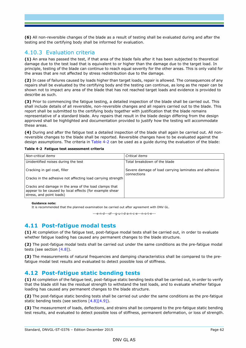
testing and the certifying body shall be informed for evaluation.
4.10.3 Evaluation criteria(1) An area has passed the test, if that area of the blade fails after it has been subjected to theoretical damage due to the test load that is equivalent to or higher than the damage due to the target load. In principle, testing of the blade can continue to reach equal severity for the other areas. This is only valid for the areas that are not affected by stress redistribution due to the damage.
(2) In case of failures caused by loads higher than target loads, repair is allowed. The consequences of any repairs shall be evaluated by the certifying body and the testing can continue, as long as the repair can be shown not to impact any area of the blade that has not reached target loads and evidence is provided to describe as such.
(3) Prior to commencing the fatigue testing, a detailed inspection of the blade shall be carried out. This shall include details of all reversible, non-reversible changes and all repairs carried out to the blade. This report shall be submitted to the certifying body together with justification that the blade remains representative of a standard blade. Any repairs that result in the blade design differing from the design approved shall be highlighted and documentation provided to justify how the testing will accommodate these areas.
(4) During and after the fatigue test a detailed inspection of the blade shall again be carried out. All non-reversible changes to the blade shall be reported. Reversible changes have to be evaluated against the design assumptions. The criteria in Table 4-2 can be used as a guide during the evaluation of the blade:
Guidance note:It is recommended that the planned examination be carried out after agreement with DNV GL.
---e-n-d---of---g-u-i-d-a-n-c-e---n-o-t-e---
4.11 Post-fatigue modal tests(1) At completion of the fatigue test, post-fatigue modal tests shall be carried out, in order to evaluate whether fatigue loading has caused any permanent changes to the blade structure.
(2) The post-fatigue modal tests shall be carried out under the same conditions as the pre-fatigue modal tests (see section [4.8]).
(3) The measurements of natural frequencies and damping characteristics shall be compared to the pre-fatigue modal test results and evaluated to detect possible loss of stiffness.
4.12 Post-fatigue static bending tests(1) At completion of the fatigue test, post-fatigue static bending tests shall be carried out, in order to verify that the blade still has the residual strength to withstand the test loads, and to evaluate whether fatigue loading has caused any permanent changes to the blade structure.
(2) The post-fatigue static bending tests shall be carried out under the same conditions as the pre-fatigue static bending tests (see sections [4.8][4.9]).
(3) The measurement of loads, deflections, and strains shall be compared to the pre-fatigue static bending test results, and evaluated to detect possible loss of stiffness, permanent deformation, or loss of strength.
Table 4-2 Fatigue test assessment criteria
Non-critical items Critical items
Unidentified noises during the test
Cracking in gel coat, filler
Cracks in the adhesive not affecting load carrying strength
Cracks and damage in the area of the load clamps that appear to be caused by local effects (for example shear stress, and point loads)
Total breakdown of the blade
Severe damage of load carrying laminates and adhesive connections
Standard, DNVGL-ST-0376 – Edition December 2015 Page 62
DNV GL AS
(1) Reporting of the tests shall include as a minimum:
— date, time, duration— test location— person responsible for the test— identity of the test blade and reference to production documentation as per section [4.2.2] (1)— statement of test blade conformance with the design documentation— reference to the test specification as per section [4.3]— identification of test equipment— description of the measuring facilities— descriptive photos of the test set-up— calibration of the measuring devices— determination of the uncertainty in the whole measurement— relevant measurement results as recorded— observations: noise, cracks, de-lamination, buckling, permanent deflections or other faults or failures
and damages observed during the tests— inspection records— any deviations from the test plan— repairs carried out during the tests— stiffness of the test rig (angular deflection at extreme loads)— temperature in the laboratory during the test and if the blade has been exposed to sunlight— temperatures in the blade (thermography can be used to illustrate fatigue tests).
4.14 Analysis of test results
4.14.1 Test evaluation report(1) Reporting of the tests result evaluation shall include as a minimum:
— reference to test report as per section [4.13]— comparison of achieved tests loads versus required test loads— comparison of recorded measurements versus predicted values— assessment of deviations from predicted values— assessment of the test results with regard to linearity— assessment of the test results with regard to fatigue strength of design details— assessment of damages and repairs— final conclusions.
(2) The test evaluation shall be carried out with regard to the criteria specified in section [4.14.2] through [4.14.4].
4.14.2 Correlation to design analysis(1) The measured blade mass, and centre of gravity, shall be compared to the specified ones. Deviations of ±3% may be accepted without further justification.
(2) The measured natural frequencies shall be compared to the predicted ones. Deviations of ±5% for the first flapwise and first edgewise frequency may be accepted without further justification.
(3) The deflection and strain measurements obtained from static bending testing (from both the pre- and the post-fatigue static tests) shall be compared to the predicted ones. Deviations of ±7% in deflection, and of ±10% in the major strain components, may be accepted without further justification.
Standard, DNVGL-ST-0376 – Edition December 2015 Page 63
DNV GL AS
When analysing the measured strain results, it should be taken into consideration that, due to the small size of a strain gauge, the reading is not always representative for a whole section of the blade.
---e-n-d---of---g-u-i-d-a-n-c-e---n-o-t-e---
(4) Any deviations beyond the tolerances described above shall be analysed with regard to the following criteria:
— root cause of the deviation— significance of the deviation with regard to the validity of the design verification analyses.
(5) The blade structure’s deflection and strain response to the test loads (from both the pre- and the post-fatigue static tests) shall be reported (e.g. in strain vs loading plots) and analysed for linearity. In cases where the structural response is non-linear, this shall be evaluated with regard to the validity of the design verification analyses.
(6) The static loads that are actually applied during testing (for both the pre- and the post-fatigue static tests) shall be compared to the specified test loads and to the design extreme loads. Any underloading during static testing shall be analysed and justified.
(7) The fatigue loads that are actually applied during testing shall be compared to the specified test loads and to the design fatigue loads, according to the criteria from section [4.10.3]. Any underloading during fatigue testing shall be analysed and justified.
4.14.3 Design and manufacturing details(1) Design and manufacturing details shall be evaluated for their criticality in terms of damage initiation. For each area on the blade, sufficient loading shall be demonstrated (i.e. the theoretical damage during the fatigue test is equal to, or higher than, the theoretical damage based on the target load), under consideration of appropriate design strength characteristics for each detail (SN curve slope, mean stress influence). If no damage to the blade structure is observed in this area, this area has passed the test.
(2) In case structural damage occurs in an area before reaching sufficient loading, the root cause shall be determined (e.g. unsafe design detail, critical manufacturing detail, manufacturing defect). Any repair of such damaged areas shall be properly specified (in accordance with the requirements of Sec.8), and agreed with DNV GL prior to its application. In addition, DNV GL may require inspecting the damaged area before and/or after the repair is carried outx.
(3) If it can be demonstrated that the root cause for the structural damage is a manufacturing defect, and if the applied repair is restoring the original blade structure, the blade test can be continued on the repaired blade. No design modification is required in this case. Corrective actions in the manufacturing process or quality control shall be applied for the series production blade. The repaired area of the blade shall be evaluated for sufficient loading (i.e. the theoretical damage during the fatigue test is equal to, or higher than, the theoretical damage based on the target load).
(4) If it is not possible to demonstrate that the root cause for the structural damage is a manufacturing defect, and if a repair is applied nonetheless in order to continue blade fatigue testing, the blade design shall be modified in a way that improves the fatigue resistance of the affected area, and in a way that is consistent with the applied repair.
(5) Any area of the blade that is repaired according to paragraphs (3) and (4) above shall be evaluated for sufficient loading (i.e. the theoretical damage during the fatigue test is equal to, or higher than, the theoretical damage based on the target load), taking into account only those load cycles occurring after the repair has been applied.
4.14.4 Correlation to load assumptions and tower clearance analysis(1) The deflections measured during static blade bending testing shall be used to confirm the design assumptions regarding the bending stiffness of the blade (as per section [2.2.1]), also in order to validate these with regard to the load assumptions.
(2) If the verification regarding clearance between rotor and tower is based on the requirements of section [2.5.11] (3) or (4), the deflections measured during static blade bending testing shall be used to
Standard, DNVGL-ST-0376 – Edition December 2015 Page 64
DNV GL AS
ensured that the bending stiffness of the outermost blade sections is properly validated during static bending testing.
4.15 Installation of lightning protection system on test blade(1) All blade-specific elements of the lightning protection system (LPS), i.e. air termination elements as well as down conductors, should be installed on the test blade prior to testing.
Guidance note:In contrast to the mere recommendation in paragraph (1) above, the installation of the LPS prior to testing may be mandatory to comply with requirements of other standards, such as DNVGL-ST-0076, section 10.3.1.2.
---e-n-d---of---g-u-i-d-a-n-c-e---n-o-t-e---
(2) The integrity of the LPS should be repeatedly verified throughout the entire test campaign, by means of visual inspection, and by measuring the electrical resistance of the entire system from air termination to root connection. Such verification should take place, and the results shall be recorded and documented, at least at the following times:
— prior to all testing— after initial static bending testing— after fatigue load testing— after post-fatigue static bending testing.
Standard, DNVGL-ST-0376 – Edition December 2015 Page 65
DNV GL AS
5.1 General(1) The manufacturer shall be qualified for the work to be carried out regarding their workshop facilities, manufacturing processes, tools and equipment as well as training and capabilities of the personnel, as per sections [5.3] through to [5.7].
(2) The manufacturer shall ensure that each rotor blade is produced in accordance with the specified materials as per Sec.3, and in accordance with the design assumptions as per Sec.2. If standard repairs are part of a certification, the requirements of Sec.8 shall apply, and shall be verified as part of a manufacturing evaluation.
(3) The manufacturing of wind turbine blades shall be carried out according to appropriate documentation, at least including approved work instructions, drawings, and quality procedures. Such documents shall cover the scope of all relevant manufacturing processes.
5.2 Manufacturing documentation(1) A production plan shall be established, including at least the following:
— description of successive manufacturing steps (and, if applicable, with reference to the corresponding manufacturing process description as per section [3.2.2])
— description of successive quality control steps.
(2) For each manufacturing step, a work instruction shall be established, including at least the following:
— detailed description of each action to be carried out, including sketches or photos if necessary— manufacturing drawings, clearly indicating dimensions, positions, and tolerances, for all individual
elements (such as fibre material plies, or bond lines)— materials to be used.
(3) For each quality control step, quality procedures and quality control sheets shall be established, including at least the following:
— required quality control measures— acceptance criteria— procedures in case of non-conformities— duties and responsibilities of the production department and the quality control department, as well as
qualification and training requirements.
(4) A complete list of materials used for manufacturing shall be established, including at least the following:
— reference to material specifications (as per section [3.2.1])— individual product details (e.g. name and trademark of manufacturer, material grade, batch number)— proof of material qualification (as per section [3.4])— proof of incoming goods inspection (as per section [5.7.3]).
5.3 Personnel(1) The personnel employed by the company shall be such as to ensure that the components can be competently prepared, manufactured and tested for critical processes. DNV GL may require proof of the technical qualifications of the staff.
(2) Responsibilities for the respective processes shall be clearly defined.
(3) The fabrication of laminates may involve certain health risks. This standard does not address these issues. All regulations with respect to safety, health and environment should be followed. It is also recommended to perform a careful evaluation of all risks involved in producing composite structures.
Standard, DNVGL-ST-0376 – Edition December 2015 Page 66
DNV GL AS
5.4.1 Environmental conditions(1) Laminating workshops shall be totally enclosed spaces capable of being heated as well as having ventilation supply and exhaust equipment. Without further proof, a shop room temperature between 16°C and 30°C with a relative humidity between 20% RH and 80% RH shall be maintained during production times. If the suppliers of the laminating resins or adhesives have specified other processing temperatures, these shall apply. In case of manufacturing or assembly processes taking place outside enclosed spaces, the required conditions for these shall be specified separately.
(2) For continuous monitoring of the climatic conditions, thermographs and hygrographs shall be installed at suitable locations. The amount and the arrangement of the instruments shall be selected depending on the operational conditions. The instruments shall bear valid calibration marks. The records on the climatic conditions shall be kept for a period of at least 10 years and made available for inspection if required.
(3) The ventilation and its equipment should not cause impairment to the materials.
(4) The work places shall be illuminated in a suitable manner. Precautionary measures should prevent the controlled curing of the laminating resin from being impaired by sun radiation or the illuminant.
(5) The laminating workshops shall be of adequate size (floor area and ceiling height), in order that the components are easily accessible and the intended production processes can take place without hindrance.
(6) All workshops, storerooms and their operational equipment shall meet the requirements of the national laws, regulations and standards. The responsibility for compliance with these requirements is solely the manufacturers’.
(7) The danger of contamination of materials for lamination should be kept to a minimum by rigorous separation of lamination areas from other production areas and storerooms. Only the quantity of materials required shall be stored in the laminating workshops; without further proof, this should not be longer than 2 days.
(8) Whilst laminating and gluing is progressing, dust generating machinery (e.g. for repair operations, or maintenance) may only be operated in the laminating workshop to a limited extent and only if fitted with a proper dust collection unit. In such a case, any influence on product quality by dust shall be quantified and controlled. Painting or spraying work is only permissible within the laminating workshop if the manufacturer can ensure that such activities will not affect the laminating quality.
(9) Any contamination from external factors that could affect a process should be taken into account when ensuring the quality of the final product.
5.4.2 Tools and equipment(1) Moulds shall match all tolerances required by the design. The surface finish shall be as specified. It shall be demonstrated that the mould surface finish can produce components with the required surface finish of the component. If moulds are heated, a controlled distribution of temperature shall be ensured
(2) The mould surface shall be dry and dust-free. Release agents containing silicone are inadmissible.
(3) All tools and equipment shall be subject to inspection and maintenance on a regular basis. For this, appropriate procedures shall be specified.
(4) All measurement equipment used in the manufacturing process, including mixing equipment for liquid raw materials, weights, thermal sensors, hygrometers, load gauges, and pressure gauges shall be subject to regular calibration.
5.5 Manufacturing capabilities with regards to tolerances and design assumptions(1) As far as manufacturing tolerances are taken into account as part of the design assumptions (i.e. as per section [3.5.6], in connection with the related partial reduction factors as per section [2.5]), it shall be ensured that these tolerances are controlled and verified during manufacturing.
Standard, DNVGL-ST-0376 – Edition December 2015 Page 67
DNV GL AS
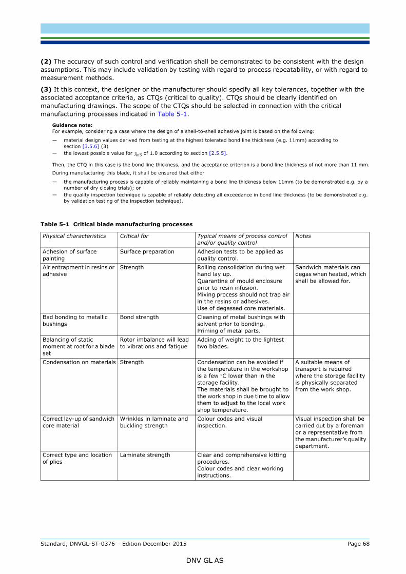
assumptions. This may include validation by testing with regard to process repeatability, or with regard to measurement methods.
(3) It this context, the designer or the manufacturer should specify all key tolerances, together with the associated acceptance criteria, as CTQs (critical to quality). CTQs should be clearly identified on manufacturing drawings. The scope of the CTQs should be selected in connection with the critical manufacturing processes indicated in Table 5-1.
Guidance note:For example, considering a case where the design of a shell-to-shell adhesive joint is based on the following:
— material design values derived from testing at the highest tolerated bond line thickness (e.g. 11mm) according to section [3.5.6] (3)
— the lowest possible value for γm3 of 1.0 according to section [2.5.5].
Then, the CTQ in this case is the bond line thickness, and the acceptance criterion is a bond line thickness of not more than 11 mm.
During manufacturing this blade, it shall be ensured that either
— the manufacturing process is capable of reliably maintaining a bond line thickness below 11mm (to be demonstrated e.g. by a number of dry closing trials); or
— the quality inspection technique is capable of reliably detecting all exceedance in bond line thickness (to be demonstrated e.g. by validation testing of the inspection technique).
Table 5-1 Critical blade manufacturing processes
Physical characteristics Critical for Typical means of process control and/or quality control
Notes
Adhesion of surface painting
Surface preparation Adhesion tests to be applied as quality control.
Air entrapment in resins or adhesive
Strength Rolling consolidation during wet hand lay up.Quarantine of mould enclosure prior to resin infusion.Mixing process should not trap air in the resins or adhesives.Use of degassed core materials.
Sandwich materials can degas when heated, which shall be allowed for.
Bad bonding to metallic bushings
Bond strength Cleaning of metal bushings with solvent prior to bonding.Priming of metal parts.
Balancing of static moment at root for a blade set
Rotor imbalance will lead to vibrations and fatigue
Adding of weight to the lightest two blades.
Condensation on materials Strength Condensation can be avoided if the temperature in the workshop is a few °C lower than in the storage facility.The materials shall be brought to the work shop in due time to allow them to adjust to the local work shop temperature.
A suitable means of transport is required where the storage facility is physically separated from the work shop.
Correct lay-up of sandwich core material
Wrinkles in laminate and buckling strength
Colour codes and visual inspection.
Visual inspection shall be carried out by a foreman or a representative from the manufacturer’s quality department.
Correct type and location of plies
Laminate strength Clear and comprehensive kitting procedures.Colour codes and clear working instructions.
Standard, DNVGL-ST-0376 – Edition December 2015 Page 68
DNV GL AS
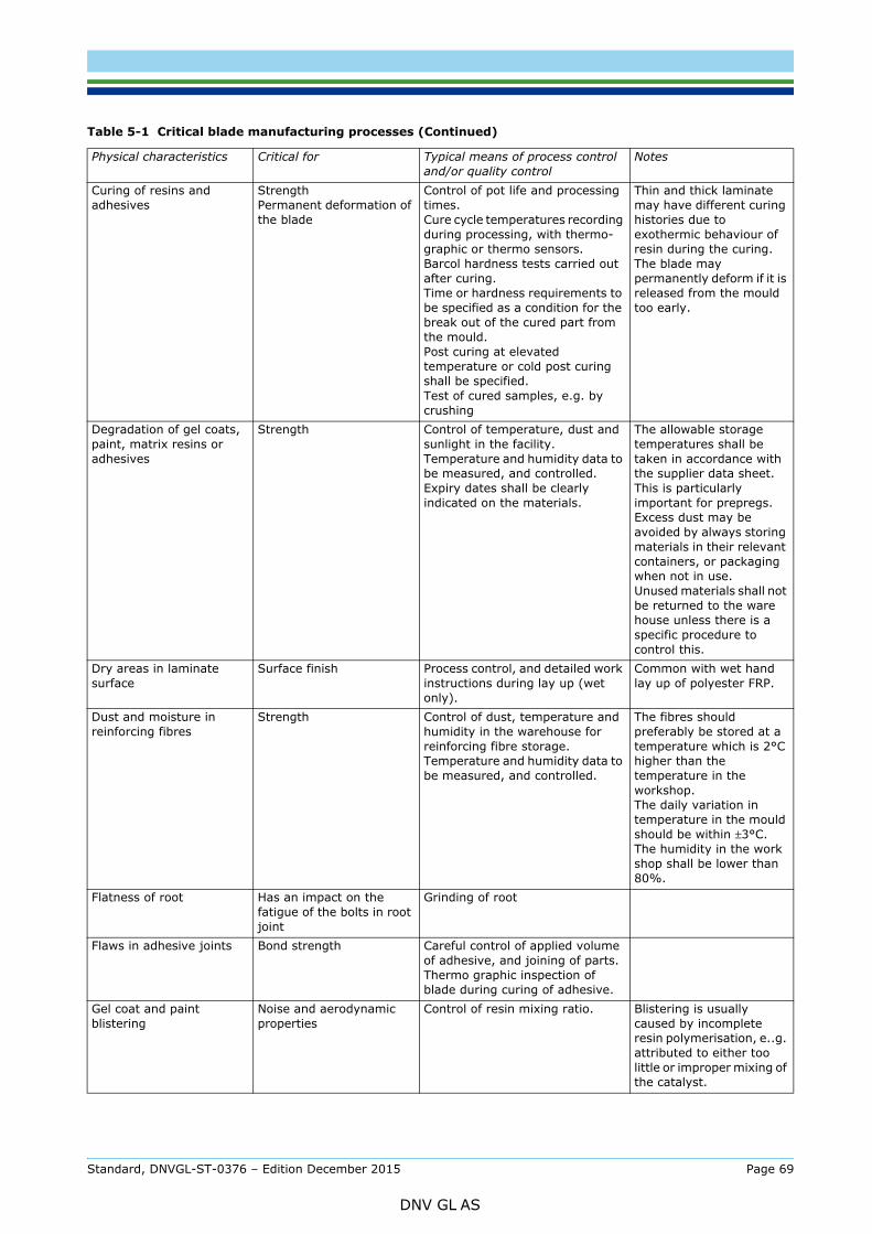
Curing of resins and adhesives
StrengthPermanent deformation of the blade
Control of pot life and processing times.Cure cycle temperatures recording during processing, with thermo-graphic or thermo sensors.Barcol hardness tests carried out after curing.Time or hardness requirements to be specified as a condition for the break out of the cured part from the mould.Post curing at elevated temperature or cold post curing shall be specified.Test of cured samples, e.g. by crushing
Thin and thick laminate may have different curing histories due to exothermic behaviour of resin during the curing.The blade may permanently deform if it is released from the mould too early.
Degradation of gel coats, paint, matrix resins or adhesives
Strength Control of temperature, dust and sunlight in the facility.Temperature and humidity data to be measured, and controlled.Expiry dates shall be clearly indicated on the materials.
The allowable storage temperatures shall be taken in accordance with the supplier data sheet. This is particularly important for prepregs.Excess dust may be avoided by always storing materials in their relevant containers, or packaging when not in use.Unused materials shall not be returned to the ware house unless there is a specific procedure to control this.
Dry areas in laminate surface
Surface finish Process control, and detailed work instructions during lay up (wet only).
Common with wet hand lay up of polyester FRP.
Dust and moisture in reinforcing fibres
Strength Control of dust, temperature and humidity in the warehouse for reinforcing fibre storage.Temperature and humidity data to be measured, and controlled.
The fibres should preferably be stored at a temperature which is 2°C higher than the temperature in the workshop.The daily variation in temperature in the mould should be within ±3°C.The humidity in the work shop shall be lower than 80%.
Flatness of root Has an impact on the fatigue of the bolts in root joint
Grinding of root
Flaws in adhesive joints Bond strength Careful control of applied volume of adhesive, and joining of parts.Thermo graphic inspection of blade during curing of adhesive.
Gel coat and paint blistering
Noise and aerodynamic properties
Control of resin mixing ratio. Blistering is usually caused by incomplete resin polymerisation, e..g. attributed to either too little or improper mixing of the catalyst.
Table 5-1 Critical blade manufacturing processes (Continued)
Physical characteristics Critical for Typical means of process control and/or quality control
Notes
Standard, DNVGL-ST-0376 – Edition December 2015 Page 69
DNV GL AS
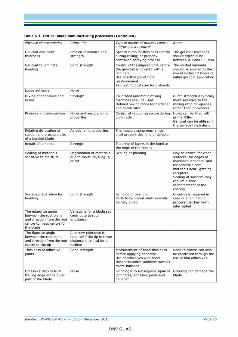
Gel coat and paint thickness
Erosion resistance and strength
Special comb for thickness control during rolling; or properly controlled spraying process
The gel coat thickness should typically be between 0.3 and 0.6 mm
Gel coat to laminate bonding
Bond strength Control of the elapsed time before the gel-coat is covered with a laminate.Use of a thin ply of fibre reinforcement.Tap testing post cure for disbonds.
The wetted laminate should be applied to the mould within 12 hours of initial gel coat application.
Loose adhesive Noise
Mixing of adhesives and resins
Strength Calibrated automatic mixing machines shall be used.Defined mixing ratios for hardener and accelerator.
Cured strength is typically more sensitive to the mixing ratio for epoxies rather than polyesters.
Pinholes in blade surface Noise and aerodynamic properties
Control of vacuum pressure during cure cycle.
Holes can be filled with primer/filler.Gel coat can be utilised in the surface finish design.
Relative dislocation of suction and pressure side of a bonded blade
Aerodynamic properties The mould closing mechanism shall prevent this kind of defects.
Repair of laminate Strength Tapering of layers in the bond at the edge of the repair.
Sealing of materials sensitive to moisture
Degradation of materials due to moisture, fungus, or rot
Sealing or painting May be critical for wood surfaces, for edges of machined laminate, and for sandwich core materials near lightning receptors.Sealing of surfaces may require a fibre reinforcement of the coating.
Surface preparation for bonding
Bond strength Grinding of peel ply.Parts to be joined shall normally be fully cured.
Grinding is required in case of a laminating process that has been interrupted
The edgewise angle between the root plane and direction from the root centre to mass centre for the blade
Variations for a blade set contribute to rotor imbalance
The flapwise angle between the root plane and direction from the root centre to the tip
A narrow tolerance is required if the tip to tower distance is critical for a turbine
Thickness of adhesive joints
Bond strength Measurement of bond thickness before applying adhesive.Use of adhesives with bond thickness control additives such as micro-balloons.
Bond thickness can also be controlled through the use of film adhesives.
Excessive thickness of trailing edge in the outer part of the blade
Noise Grinding with subsequent repair of laminates, adhesive joints and gel-coat.
Grinding can damage the blade.
Table 5-1 Critical blade manufacturing processes (Continued)
Physical characteristics Critical for Typical means of process control and/or quality control
Notes
Standard, DNVGL-ST-0376 – Edition December 2015 Page 70
DNV GL AS
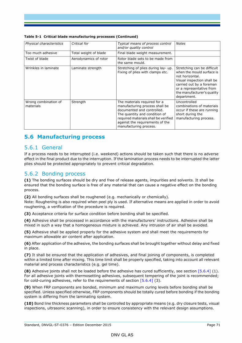
5.6 Manufacturing process
5.6.1 GeneralIf a process needs to be interrupted (i.e. weekend) actions should be taken such that there is no adverse effect in the final product due to the interruption. If the lamination process needs to be interrupted the latter plies should be protected appropriately to prevent critical degradation.
5.6.2 Bonding process(1) The bonding surfaces should be dry and free of release agents, impurities and solvents. It shall be ensured that the bonding surface is free of any material that can cause a negative effect on the bonding process.
(2) All bonding surfaces shall be roughened (e.g. mechanically or chemically). Note: Roughening is also required when peel ply is used. If alternative means are applied in order to avoid roughening, a verification of the procedure is required.
(3) Acceptance criteria for surface condition before bonding shall be specified.
(4) Adhesive shall be processed in accordance with the manufacturers’ instructions. Adhesive shall be mixed in such a way that a homogeneous mixture is achieved. Any intrusion of air shall be avoided.
(5) Adhesive shall be applied properly for the adhesive system and shall meet the requirements for maximum allowable air content after application.
(6) After application of the adhesive, the bonding surfaces shall be brought together without delay and fixed in place.
(7) It shall be ensured that the application of adhesives, and final joining of components, is completed within a limited time after mixing. This time limit shall be properly specified, taking into account all relevant material and process characteristics (e.g. gel time).
(8) Adhesive joints shall not be loaded before the adhesive has cured sufficiently, see section [5.6.4] (1). For all adhesive joints with thermosetting adhesives, subsequent tempering of the joint is recommended; for cold-curing adhesives, refer to the requirements of section [5.6.4] (3).
(9) When FRP components are bonded, minimum and maximum curing levels before bonding shall be specified. Unless specified otherwise, FRP components should be totally cured before bonding if the bonding system is differing from the laminating system.
(10) Bond line thickness parameters shall be controlled by appropriate means (e.g. dry closure tests, visual inspections, ultrasonic scanning), in order to ensure consistency with the relevant design assumptions.
Too much adhesive Total weight of blade Final blade weight measurement.
Twist of blade Aerodynamics of rotor Rotor blade sets to be made from the same mould.
Wrinkles in laminate Laminate strength Stretching of plies during lay- up.Fixing of plies with clamps etc.
Stretching can be difficult when the mould surface is not horizontal.Visual inspection shall be carried out by a foreman or a representative from the manufacturer’s quality department.
Wrong combination of materials
Strength The materials required for a manufacturing process shall be documented and controlled.The quantity and condition of required materials shall be verified against the requirements of the manufacturing process.
Uncontrolled combinations of materials occur if these are running short during the manufacturing process.
Table 5-1 Critical blade manufacturing processes (Continued)
Physical characteristics Critical for Typical means of process control and/or quality control
Notes
Standard, DNVGL-ST-0376 – Edition December 2015 Page 71
DNV GL AS
(1) The laminate shall be built up in accordance with the approved production specification.
(2) The reinforcement layers shall be adequately deaerated and compressed so that resin enrichment and air containment is avoided, the required fibre content is ensured.
(3) The maximum thickness of material that can be cured in one step is determined by considering the maximum number of layers from which air can still be totally removed and by the maximum permissible heat generation.
(4) If the laminating process is interrupted for more than two days in the case of widely used cold-curing resins, the surface of the cured laminate shall be roughened and cleaned to obtain a surface providing adequate bonding. Deviating manufacturers’ instructions shall be followed.
(5) Parallel or insert linings shall be free from moisture and impurities. Their surfaces to be bonded to the laminate shall be prepared suitably, see section [5.6.2] (1).
(6) Splicing of layers (e.g. at the end of a glass fabric roll) should be avoided; if it cannot be avoided, it is only acceptable if an appropriate procedure is specified.
(7) Methods and processes for preparing kits (such as preformed fibre stacks, or sandwich cores) shall be properly specified, in a way to ensure reproducible results.
5.6.4 Curing and tempering(1) Components may only be removed from the moulds after adequate curing of the resin and the adhesive. The required curing time depends on the curing temperature, the resin systems used and the forces that occur while separating the component from its mould. The curing time shall be verified by experiment and documented.
(2) Resin systems which cure under pressure, UV radiation and/or increased temperature shall be treated in accordance with the resin supplier´s instructions or the results of suitable previous investigations.
(3) Right after curing, the components shall be tempered at elevated temperature if necessary to assure the required material properties. The maximum allowable temperature is determined by the materials in the component, whilst the heat distortion temperature of the structural resins may not be exceeded. Cold-curing systems which are not subsequently tempered shall be stored for a specified period of time under curing conditions. This period shall be at least 30 days, unless shorter periods are proven to be sufficient by quantification of achieved cure or strength levels.
(4) For each component, the relevant processing temperature profiles shall be specified, at least including application temperature and time, and cure temperature and time (or a definition of a minimum required degree of curing to be achieved by the curing process for each resin system, e.g. in terms of a minimum Tg.
5.6.5 Sealing(1) Laminate surfaces without surface protection shall be sealed after curing and tempering, using suitable agents. Sealing should be performed as required, giving consideration to applied loading, environmental exposure etc.; the necessity for sealing should be evaluated taking into consideration the various areas of the blade (inside, outside) and local details (e.g. exposed fibres and exposed core materials).
(2) The sealing materials used shall not impair the properties of the laminate. They shall also suit the intended purpose of the component.
5.6.6 Gelcoat and paint applicationIt shall be ensured that the interfaces between gelcoat, paint, and structural laminates have the required adhesion strength. For application of the first layer of laminate to the gelcoat, the minimum degree of cure of the gelcoat shall be specified. Also, the laminate has to be sufficiently cured before applying paint.
5.6.7 Resin application(1) Resin and reaction agent shall be mixed homogeneously and without any intrusion of air. If mixing machines are used, a procedure to verify and control the correct mixing ratio for each manufacturing cycle shall be defined.
Standard, DNVGL-ST-0376 – Edition December 2015 Page 72
DNV GL AS
plus any other applicable regulations shall be observed in addition to this standard.
(3) During production, the processing time for the mixed resin compound specified by the resin supplier shall not be exceeded. In the absence of such information, the pot time shall be established in a preliminary test and the processing aligned with DNV GL.
(4) The resin shall be applied void-free.
(5) For vacuum assisted debulking, the process parameters shall be defined.
(6) For resin infusion, the relevant processing parameters shall be specified, at least including resin application temperature and time, vacuum set-up, as well as level of applied differential pressure for infusion, and cure.
5.6.8 Finishing process(1) It shall be ensured that the specified machining processes (cutting and grinding) have no adverse effects on the mechanical properties of the blade structure.
(2) Appropriate measures shall be implemented against the risk of overheating the laminate, or of introducing excessive local stresses into the blade structure.
(3) Cutting and grinding work is only permissible within the laminating workshop if the manufacturer can ensure that such activities will not affect the laminating quality.
(4) The paint shall be applied in a uniform layer of thickness in accordance with the production specification and shall provide the required interface adhesion between paint and structural laminate.
(5) The paint application and cure process shall be properly controlled through dedicated painting procedures, based on the paint manufacturer's recommendations.
(6) All surfaces to be painted shall be roughened either mechanically or chemically in advance.
(7) Painting or spraying work is only permissible within the laminating workshop if the manufacturer can ensure that such activities will not affect the laminating quality.
5.6.9 Sandwich core material(1) Rigid plastic foam used as core material should be degassed and tempered beforehand.
(2) When wood materials are used (e.g. balsa as sandwich cores), the moisture content shall be properly controlled, in order to ensure compatibility with subsequent processing steps.
Guidance note:Especially for slotted core materials, it should be ensured that the material properties at the end of processing are in accordance with the design value assumptions.
---e-n-d---of---g-u-i-d-a-n-c-e---n-o-t-e---
5.7 Quality management
5.7.1 General(1) Provided the manufacturer operates and applies a quality management (QM) system in accordance with a recognized standard, and this has been evaluated by DNV GL, a portion of the proofs required in this Standard may be provided within the context of the QM system. A certification of the QM system by an accredited certification body is recognized through the assessment by DNV GL.
(2) Recognition of the QM system obliges the manufacturer to observe the requirements laid down in this Standard. The obligation for proof of this rests on the company. DNV GL verifies the effectiveness of the system and the work-specific requirements on the basis of the documentation submitted by the company, e.g. within the context of shop approval, and checks it, at its discretion, by random inspections or by witnessing tests within the QM system.
(3) The manufacturer is responsible for ensuring that all tests and inspections laid down in accordance with this Standard, as well as with any standards, specifications and other regulations that are also applicable, are carried out.
Standard, DNVGL-ST-0376 – Edition December 2015 Page 73
DNV GL AS
or to production processes which can be expected to have a significant effect on product quality. DNV GL reserves the right to check these issues (extraordinary inspection) and to review the approval of the QM system.
(5) Insofar as the certification of the QM system of a certification body was recognized by DNV GL, the manufacturer is under an obligation to inform DNV GL without delay about the loss of the certificate’s validity.
5.7.2 Requirements for the quality management system(1) The QM system shall meet the requirements of ISO 9001.
(2) The QM system shall be worked out in detail in writing. The QM system consists of at least a manual, procedures and work instructions in sufficient detail.
(3) For the manufacturers of products who do not pursue their own development activities, the exclusion of clause 7.3 (“Design and development”) within ISO 9001 is permissible.
5.7.3 Incoming inspection(1) The characteristic values and properties of the materials shall be verified by the manufacturer for consistency with design assumptions. The following are required as a minimum:
— fibre products— gelcoat resins— paints— laminating resins— prepregs— core materials— adhesives.
(2) Methods for incoming materials inspection could include:
— incoming inspection certificates— verification by suppliers documented quality control procedures— internal checks for any damage— specified internal testing with defined sampling rate or frequency.
Guidance note:Incoming inspection certificates may be based on ISO 10474-2.2 (EN 10204-2.2) and ISO 10474-3.1 (EN 10204-3.1) in connection with ISO 10474 (EN 10204), or equivalent alternatives.
---e-n-d---of---g-u-i-d-a-n-c-e---n-o-t-e---
(3) Acceptance criteria for these, including tolerances shall be defined in the documentation.
(4) Bolts (such as root attachment bolts) shall be verified for consistency with design assumptions, e.g. for compliance with the requirements for the strength category as specified in the design.
(5) Suitable procedures shall be established by the manufacturer to ensure continuous inspection of incoming materials.
5.7.4 Material handling and storage(1) The temperature and humidity in the all store rooms shall be recorded continuously. All materials shall be shall be stored in accordance with the requirements of the supplier and with this Standard.
(2) Laminating resin compounds and adhesives should be transported and stored according to the supplier’s instructions.
(3) Prepregs shall be stored in special refrigerated compartments in accordance with the supplier’s instructions.
Standard, DNVGL-ST-0376 – Edition December 2015 Page 74
DNV GL AS
closed, or else otherwise suited to avoid contamination and environmental degradation due to dust, temperature, and humidity. Moisture sensitive materials exposed to air humidity shall be stored in spaces with continuous moisture recordings and without further proof the humidity should not exceed 70% RH, and 80% RH only for short periods.
(5) Storage should be arranged so that the designation of the materials, the storage conditions and maximum storage periods are easily visible. Materials whose storage period has been exceeded shall be marked as being out of conformity and prohibited for use, and then as soon as possible removed from the store or shall be kept in a clearly distinguished exclusion area until the material is proven to be suitable for use again.
(6) Quantities of materials should be brought to the processing rooms in good time to allow the whole material volume to reach the processing temperature (ΔT ≤ 2°C) with the packaging remaining closed.
Guidance note:This temperature adjustment is necessary to avoid condensation of humidity on the material surface.
---e-n-d---of---g-u-i-d-a-n-c-e---n-o-t-e---
(7) Reactive and moisture sensitive materials stored in packages removed from store and opened may be returned to store only in defined cases (e.g. hot-curing prepregs). The packages have to be clearly designated in such a case.
5.7.5 Quality control(1) Quality Control of FRP component production comprises control of the raw material, surveillance during production, and checking the quality of the finished components.
(2) As the work progresses, the individual production steps shall be marked off by the employees responsible for each stage, on the basis of the prescribed documentation. Quality procedures shall clearly specify the duties and responsibilities of the production department, and the quality control department, as well as qualification and training requirements.
(3) For bonding, the manufacturing shop should have at least two persons working in production with an appropriate technical qualification.
(4) The batch numbers of the materials used in the component shall be recorded in the production documentation so that traceability is ensured.
(5) From every batch of reaction resin compound, a sample shall be taken and tested. If mixing machines are used, at least one sample per joining process (interruptions of up to one hour can be neglected) shall be taken. The same applies for any change at the mixing machine or any of the materials. The samples shall be checked for their degree of curing and the results shall be recorded.
Guidance note:Storage of retained samples for at least the duration of the warranty period is recommended.
---e-n-d---of---g-u-i-d-a-n-c-e---n-o-t-e---
(6) Reinforcing layers introduced into the laminate shall be checked during the production process.
(7) For confirming the material values used as a basis for the strength calculations, it may be required to produce reference laminates in parallel.
5.7.6 Non-conformities(1) Procedures for the control of nonconforming outputs shall be in place (e.g. as part of a QM system according to ISO 9001).
(2) It shall be ensured that non-conformities in manufacturing (e.g. exceedance of tolerances or acceptance criteria) are detected, evaluated, corrected as necessary, and documented.
(3) It may be required to involve the designer in this process.
(4) It may be appropriate to include standard measures (acceptance without repair, or standard repairs) in the initial design (see section [2.4.4]).
Standard, DNVGL-ST-0376 – Edition December 2015 Page 75
DNV GL AS
(1) The following data shall at least be recorded for each blade produced, and should be stored for the design life of the blade:
— blade serial number or similar unique identification— all critical to quality (CTQ) process and design items as measured or recorded— checks, approvals and inspection lists, and the corresponding limits— record of non-conformance reports (NCRs), decisions about acceptance or corrective actions— batch numbers of all materials with required traceability— identity (serial number or equivalent) of toolings used in the critical manufacturing processes— revision numbers of drawings and work instructions used during the manufacturing— inspection and acceptance of incoming materials— identification of personnel participating in critical processes by name or employee number, if possible— record of quality inspections carried out during the manufacturing process, including signatures of
responsible personnel— thermograph and hydrograph records— curing cycle history of the laminates, recording the temperature and pressure at critical locations during
the curing, where applicable— identification of any test coupons that are manufactured together with the blade— any repairs carried out during manufacturing.
(2) As part of the production documents, also the final inspection shall be recorded. At least the checks listed below are required to be performed or checked for completeness (if performed earlier in manufacturing process) as part of the final inspection for every blade. A specific test procedure and acceptance criteria shall be in place for each inspection:
— plausibility and completeness check of the data and entries in control sheets and inspection lists. Verification of data (CTQ) compliance with acceptance criteria
— work progress slips and check sheets which accompany the rotor blade through the production process— check of the geometry including accuracy of profile data, trailing edge thickness— determination of the mass and the centre of gravity— check of the balance quality for each set of blades— surface quality and appearance— drainage system;— functional checks of installed systems (to include – but not limited to)
— brake systems— flaps or moving devices— sensors and monitoring systems— lightning protection systems.
(3) Each part of the quality control records shall be traceable to the serial number of the blade in production (e.g. by ensuring that each page of quality control record indicates the serial number of the blade in production).
Standard, DNVGL-ST-0376 – Edition December 2015 Page 76
DNV GL AS

6.1 Requirements for documentationAll handling, transport and installation procedures shall be properly described and documented, including:
— blade handling procedures and instructions— position of lifting points (these shall also be clearly marked on the surface of each blade)— description and drawings of the blade transport and support devices— specification of maximum loads expected to occur during transport, including offshore transport
(e.g. accelerations)— installation procedures, including bolt pre-tensioning parameters as per section [2.2.2] (2).
6.2 Technical requirements(1) For all handling, transport and installation conditions, it shall be demonstrated that the loads occurring on the blades do not damage the structure. This shall be carried out in accordance with the requirements for design analyses as per section [2.5].
(2) It shall be demonstrated that the specified transport and support devices do not provoke any local damage to the blade (such as surface indentations, sandwich core crushing, or cracks in the trailing edge).
Standard, DNVGL-ST-0376 – Edition December 2015 Page 77
DNV GL AS

7.1 General(1) The operator of a wind turbine shall ensure that, as long as it is in operation, the installed rotor blades are inspected and maintained on a regular basis.
(2) Inspections and maintenance shall take place in regular time intervals, and shall be based on the procedures specified by the original blade manufacturer (e.g. in manuals).
(3) Depending on the context, inspections and maintenance may become an obligation as part of a certification, e.g. in the following cases:
— for project certification
— for certification of an extended duration of operation.
7.2 Requirements for service providers(1) Any service provider carrying out inspections and maintenance shall be capable to do so. It shall be ensured that the service provider has:
— up-to-date service manuals for the relevant blade type
— all required equipment
— sufficiently qualified personnel.
Guidance note:Formal requirements may apply depending on the certification or regulatory context, including the requirement to demonstrate knowledge and quality of work with regards to the OEM’s requirements, in order to ensure and maintain the performance of the original blade and to prevent inferior practices.
---e-n-d---of---g-u-i-d-a-n-c-e---n-o-t-e---
(2) For each inspection and maintenance intervention, a report shall be prepared by the service provider. This report shall be submitted to the wind turbine operator immediately. The wind turbine operator shall store all reports for as long as the wind turbine is in service. Likewise, the service provider shall store all reports for at least five years.
7.3 Technical requirements(1) The detailed technical scope of inspections and maintenance shall be specified by the original blade manufacturer as part of their documentation. It should at least include:
— outer surface quality
— structural integrity of laminates, from the outer as well as the inner surface
— adhesive joints at leading and trailing edge
— adhesive joints in the inside (such as shear web joints)
— attached items (e.g. lightning protection)
— lightning events
— corrosion and pre-tension of bolts
— mechanisms or installed systems, if applicable.
(2) The scope should include regular inspections carried out at the proximity of the blade, i.e. by directly accessing the outer as well as the inner blade surface; in addition, it may also include distant visual inspection (e.g. through a telescope, or using cameras). Inspection schedules that are exclusively based on distant visual inspection should be avoided.
(3) If repairs have to be carried out, the requirements specified in Sec.8 shall apply.
Standard, DNVGL-ST-0376 – Edition December 2015 Page 78
DNV GL AS
8.1 Scope(1) This section 8 specifies requirements which shall be complied with when repairing rotor blades as part of the manufacturing process or in early phases of operations, with the objective to restore a condition of the blade which can be considered still compliant with the certification requirements of sections 1 to 5 of this standard.
(2) The requirements stated in this section 8 shall apply to all repairs affecting the structural integrity and structural behaviour of the rotor blade, its aerodynamic characteristics, and any other functionality.
(3) Depending on the context, the requirements stated in this section 8 may become applicable as basis for certification, e.g. in the following cases:
— if standard repairs are part of a design evaluation, as per section [2.4.4]— if repairs are part of a blade test evaluation, as per section [4.2.3]— if repairs are part of a manufacturing evaluation, as per Sec.5— for project certification.
Guidance note:Typically, these requirements may be applied as basis for certification of repairs of manufacturing non-conformities carried out by the OEM during or after manufacturing; or as a basis for certification of standard repair measures specified by the OEM.
---e-n-d---of---g-u-i-d-a-n-c-e---n-o-t-e---
8.2 Design verification of repairs
8.2.1 Repair specification(1) For each type of structural repair, a repair specification shall be established. Such a repair specification may be intended for repeated application to a specific type of manufacturing non-conformity or damage.
(2) A repair specification shall at least include the following:
— the regions of the blade, as well as the type and maximum size of the non-conformity to which the repair is applicable
— preparation for repair (cutting, drilling, grinding, chamfering, cleaning), including drawings— materials to be used in the repair, including a statement that these are in accordance with the
requirements of section [8.2.2], and including humidity limits for balsa if applicable— repair method and process including specification for repair interruptions if applicable (e.g. peel ply),
and including climatic conditions for processing— repair lay-up, including drawings, minimum overlaps used for each laminate type, and requirements for
butt joint offsets if applicable— tolerances for adhesive joints if applicable— resin-hardener mixing ratio— principle of vacuum set-up and level of applied differential pressure (if applicable)— processing temperature profiles, including application temperature and time, and cure temperature and
time— finishing— quality check and acceptance criteria (e.g. regarding Tg, fibre volume content, porosity).
(3) It shall be demonstrated (as required in sections [8.2.2] to [8.2.5]) that the intended repairs do not invalidate the original blade certification. For this, the repair specification shall, where necessary, make appropriate reference to the detailed structural design of the blade at the affected areas, including at least:
— structural lay-up— specified materials
Standard, DNVGL-ST-0376 – Edition December 2015 Page 79
DNV GL AS
— applied loading intensity and distribution— margins from the design verification analyses
8.2.2 Materials(1) It shall be ensured that the materials used for repair are identical, or have comparable or better performance than the ones used in the original blade structure.
(2) The requirements of Sec.3 shall apply for repair materials.
(3) It shall be ensured that the materials used for repair are compatible with the repair laminating and curing process.
(4) If the repair materials are not identical with the ones used in the original blade structure, it shall be demonstrated that their properties are equivalent or better, in particular with respect to the mechanical properties and the temperature stability. This shall be achieved by testing according to the requirements in Sec.3. In addition, the compatibility of the repair materials with the original ones shall also be verified. It shall be ensured that the matrix used and adhesive resins do not have any detrimental effects on the adjacent materials.
(5) Without further verification, and unless the original thermosetting resin is used, the elongation at break of the thermosetting resins used for the repair shall be at least 2.5%. When using highly reactive fast-setting resins, the risk associated with residual stresses in the repair area shall be considered.
(6) It should be ensured the all materials used for repair are properly controlled regarding their quality (i.e. incoming inspections, traceability, storage and handling) in compliance with the requirements of Sec.5.
8.2.3 Design(1) Each repair affecting the structural integrity and structural behaviour of the rotor blade shall be properly designed.
(2) For repairs on laminates and sandwich constructions, design verification shall be carried out according to sections [8.2.4] and [8.2.5].
(3) For repairs on adhesive joints, the verification analyses shall at least include:
— design assumptions for material properties— adhesive joint analyses— bond thickness and width— strength of the repaired structure, and margins.
(4) For non-structural repairs, no verification analyses are required. Non-structural repairs may include:
— paint or gelcoat repairs— minor filling of surface to meet geometry requirements— replacement of lightning protection parts.
8.2.4 Verification analyses(1) Strength assumptions made for the verification analyses shall be substantiated by testing as per section [8.2.5].
(2) The verification analyses for the repaired structure shall demonstrate that the requirements regarding structural design verification (i.e. the ones specified in Sec.2) are still fulfilled. For these repair analyses, the partial reduction factors required in section 2 shall be applied and selected in connection with the repair process and repair analysis methods.
(3) The repair verification analyses shall cover all failure modes relevant for the given repair work. For laminate repairs, the repair verification analyses shall at least include fibre failure analyses as per section [2.5.2] and [2.5.3], as well as verification for an equivalent stiffness of the structure.
Standard, DNVGL-ST-0376 – Edition December 2015 Page 80
DNV GL AS
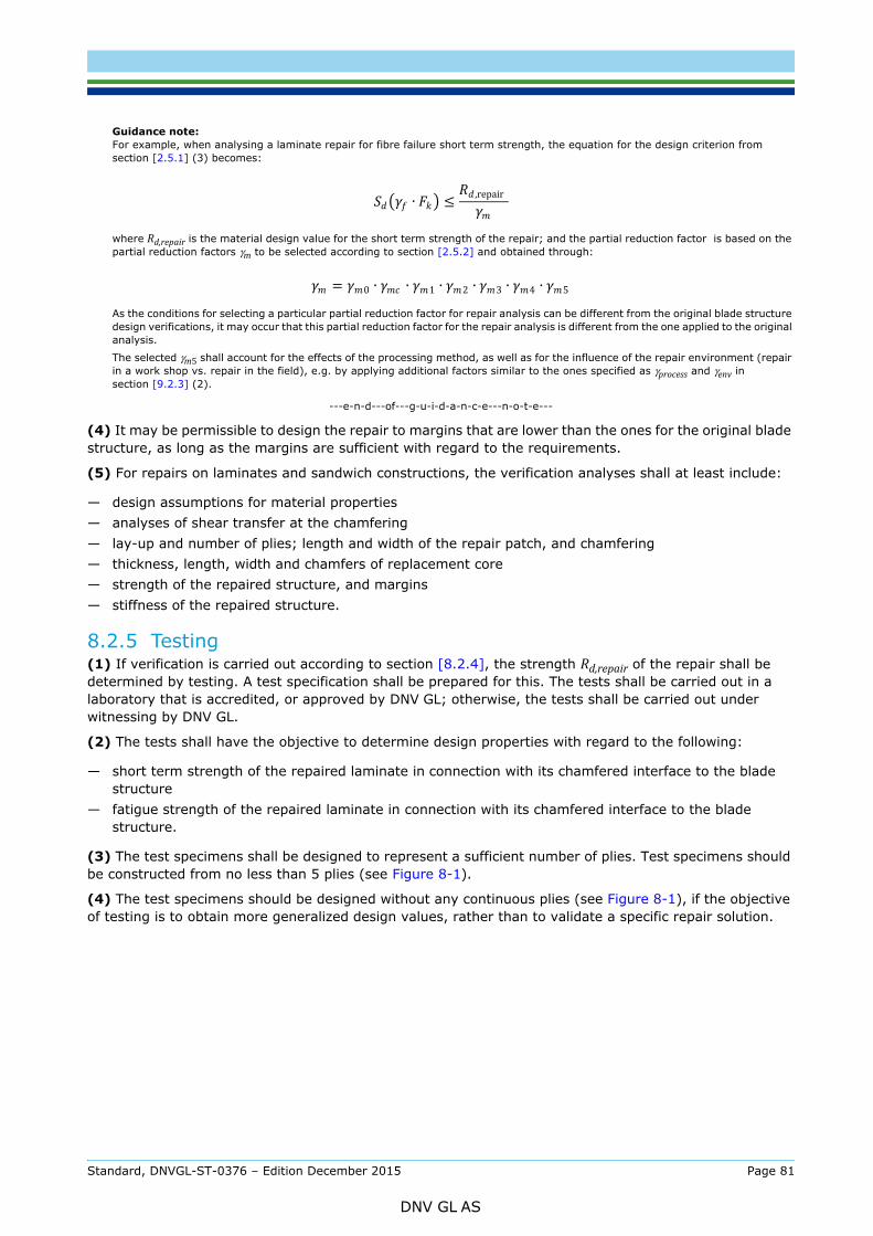
For example, when analysing a laminate repair for fibre failure short term strength, the equation for the design criterion from section [2.5.1] (3) becomes:
where Rd,repair is the material design value for the short term strength of the repair; and the partial reduction factor is based on the partial reduction factors γm to be selected according to section [2.5.2] and obtained through:
As the conditions for selecting a particular partial reduction factor for repair analysis can be different from the original blade structure design verifications, it may occur that this partial reduction factor for the repair analysis is different from the one applied to the original analysis.
The selected γm5 shall account for the effects of the processing method, as well as for the influence of the repair environment (repair in a work shop vs. repair in the field), e.g. by applying additional factors similar to the ones specified as γprocess and γenv in section [9.2.3] (2).
---e-n-d---of---g-u-i-d-a-n-c-e---n-o-t-e---
(4) It may be permissible to design the repair to margins that are lower than the ones for the original blade structure, as long as the margins are sufficient with regard to the requirements.
(5) For repairs on laminates and sandwich constructions, the verification analyses shall at least include:
— design assumptions for material properties— analyses of shear transfer at the chamfering— lay-up and number of plies; length and width of the repair patch, and chamfering— thickness, length, width and chamfers of replacement core— strength of the repaired structure, and margins— stiffness of the repaired structure.
8.2.5 Testing(1) If verification is carried out according to section [8.2.4], the strength Rd,repair of the repair shall be determined by testing. A test specification shall be prepared for this. The tests shall be carried out in a laboratory that is accredited, or approved by DNV GL; otherwise, the tests shall be carried out under witnessing by DNV GL.
(2) The tests shall have the objective to determine design properties with regard to the following:
— short term strength of the repaired laminate in connection with its chamfered interface to the blade structure
— fatigue strength of the repaired laminate in connection with its chamfered interface to the blade structure.
(3) The test specimens shall be designed to represent a sufficient number of plies. Test specimens should be constructed from no less than 5 plies (see Figure 8-1).
(4) The test specimens should be designed without any continuous plies (see Figure 8-1), if the objective of testing is to obtain more generalized design values, rather than to validate a specific repair solution.
∙ ≤ ,repair
= 0 ∙ ∙ 1 ∙ 2 ∙ 3 ∙ 4 ∙ 5
Standard, DNVGL-ST-0376 – Edition December 2015 Page 81
DNV GL AS
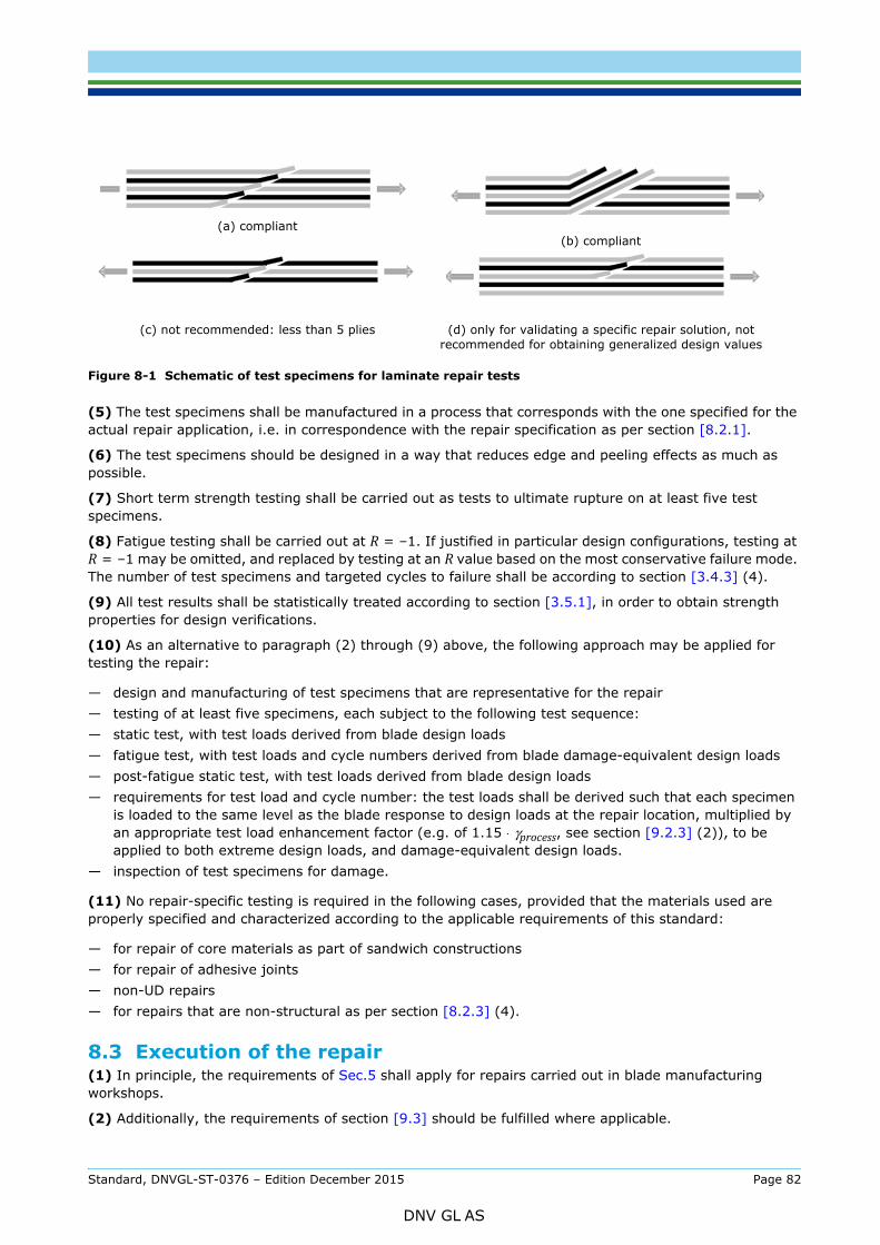
Figure 8-1 Schematic of test specimens for laminate repair tests
(5) The test specimens shall be manufactured in a process that corresponds with the one specified for the actual repair application, i.e. in correspondence with the repair specification as per section [8.2.1].
(6) The test specimens should be designed in a way that reduces edge and peeling effects as much as possible.
(7) Short term strength testing shall be carried out as tests to ultimate rupture on at least five test specimens.
(8) Fatigue testing shall be carried out at R = –1. If justified in particular design configurations, testing at R = –1 may be omitted, and replaced by testing at an R value based on the most conservative failure mode. The number of test specimens and targeted cycles to failure shall be according to section [3.4.3] (4).
(9) All test results shall be statistically treated according to section [3.5.1], in order to obtain strength properties for design verifications.
(10) As an alternative to paragraph (2) through (9) above, the following approach may be applied for testing the repair:
— design and manufacturing of test specimens that are representative for the repair— testing of at least five specimens, each subject to the following test sequence:— static test, with test loads derived from blade design loads— fatigue test, with test loads and cycle numbers derived from blade damage-equivalent design loads— post-fatigue static test, with test loads derived from blade design loads— requirements for test load and cycle number: the test loads shall be derived such that each specimen
is loaded to the same level as the blade response to design loads at the repair location, multiplied by an appropriate test load enhancement factor (e.g. of 1.15 ⋅ γprocess, see section [9.2.3] (2)), to be applied to both extreme design loads, and damage-equivalent design loads.
— inspection of test specimens for damage.
(11) No repair-specific testing is required in the following cases, provided that the materials used are properly specified and characterized according to the applicable requirements of this standard:
— for repair of core materials as part of sandwich constructions— for repair of adhesive joints— non-UD repairs— for repairs that are non-structural as per section [8.2.3] (4).
8.3 Execution of the repair(1) In principle, the requirements of Sec.5 shall apply for repairs carried out in blade manufacturing workshops.
(2) Additionally, the requirements of section [9.3] should be fulfilled where applicable.
(a) compliant
(c) not recommended: less than 5 plies
(b) compliant
(d) only for validating a specific repair solution, not recommended for obtaining generalized design values
Standard, DNVGL-ST-0376 – Edition December 2015 Page 82
DNV GL AS
9.1 Scope(1) This section 9 specifies requirements which shall be complied with when blades are repaired by repair service providers during operation.
(2) The requirements stated in this section 9 shall apply to all repairs affecting the structural integrity and structural behaviour of the rotor blade, its aerodynamic characteristics, and any other functionality.
(3) Depending on the context, the requirements stated in section 9 may become applicable e.g. in the following cases:
— for a repair shop approval— for approving a specific in-field repair.
Guidance note:Typically, these requirements may be applied as basis for repair shop approvals of repair service providers, for specific repairs carried out during operation. As such, section 9 will usually not be within the scope of component certification for blades, or type certification for turbines.
---e-n-d---of---g-u-i-d-a-n-c-e---n-o-t-e---
9.2 Design verification of repairsStandard repairs applied for in-services damages should be specified and designed (e.g. by the OEM) according to section [8.2]. In the absence of any such specifications, the requirements of section [9.2] may be applied instead.
9.2.1 Repair specification(1) For each structural repair, a repair specification shall be established. Such a repair specification may be of either of the following types:
— A generic repair specification, with the objective to be applied repeatedly to a specific type of damage.— A specification dedicated to a specific, one-time repair action.
(2) A repair specification shall at least include the following:
— description and drawings of the type of damage (including location and size) to be repaired— description and drawings of the blade structure at the affected area (geometry, materials, lay-up,
thicknesses, widths)— preparation for repair (cutting, drilling, grinding, chamfering, cleaning), including drawings— materials to be used in the repair, including a statement that these are in accordance with the
requirements of section [8.2.2], and including humidity limits for balsa if applicable— repair method and process including specification for repair interruptions if applicable (e.g. peel ply),
and including climatic conditions for processing— repair lay-up, including drawings, minimum overlaps used for each laminate type, and requirements for
butt joint offsets if applicable— tolerances for adhesive joints if applicable— resin-hardener mixing ratio— principle of vacuum set-up and level of applied differential pressure (if applicable)— processing temperature profiles, including application temperature and time, and cure temperature and
time— finishing— quality check and acceptance criteria (e.g. regarding Tg, fibre volume content, porosity).
For a generic repair specification (as opposed to a specification dedicated to a specific, one-time repair action), it may not be possible to describe all the details listed above, in which case these details may be omitted and equivalent descriptions shall be provided.
Standard, DNVGL-ST-0376 – Edition December 2015 Page 83
DNV GL AS
E.g., instead of the exact location and size of the damage, a generic repair specification may indicate the regions of the blade and the maximum damage size to which it is applicable; or, instead of the exact lay-up and thickness of the affected area, a generic repair specification may indicate over which range of thicknesses and for which types of lay-up it is applicable.
---e-n-d---of---g-u-i-d-a-n-c-e---n-o-t-e---
(3) It shall be demonstrated that the intended repairs do not invalidate the original blade certification. For this, the service provider responsible for the repair specification shall make sure to obtain sufficient knowledge about the original blade design at the location of repair, including:
— structural lay-up— specified materials— material properties, including strength and stiffness— applied loading intensity and distribution— margins from the design verification analyses
Whenever no explicit reference to design documentation can be made, justified assumptions regarding structural lay-up and material properties shall be documented in the repair specification, in order to ensure that the strength and stiffness of the repaired structure is not unduly reduced as compared to the original structure.
9.2.2 Materials(1) It shall be ensured that the materials used for repair are identical, or have comparable or better performance than the ones used in the original blade structure.
(2) In general, all materials used in repairs shall fulfil the requirements for DNV GL material approval (according to the references in Table 1-2)
(3) It shall be ensured that the materials used for repair are compatible with the repair laminating and curing process.
(4) If the repair materials are not identical with the ones used in the original blade structure, it shall be demonstrated that their properties are equivalent or better, in particular with respect to the mechanical properties and the temperature stability. This shall be achieved by testing according to the requirements in Sec.3. In addition, the compatibility of the repair materials with the original ones shall also be verified. It shall be ensured that the matrix used and adhesive resins do not have any detrimental effects on the adjacent materials.
(5) Without further verification, and unless the original thermosetting resin is used, the elongation at break of the thermosetting resins used for the repair shall be at least 2.5%. When using highly reactive fast-setting resins, the risk associated with residual stresses in the repair area shall be considered.
(6) It should be ensured the all materials used for repair are properly controlled regarding their quality (i.e. incoming inspections, traceability, storage and handling) in compliance with the requirements of Sec.5.
9.2.3 Simplified design verification(1) If no standard repair is specified (e.g. by the OEM) according to section [8.2], the approach described in this section [9.2.3] may be applied for laminates and sandwich constructions. In this case, no further verification or testing is required.
(2) The minimum chamfer length in the longitudinal direction shall be determined according to the following equation:
where:
lchamfer minimum chamfer length per repair plyσ11,t,repair tensile ultimate strength of the repair laminate (obtained from material testing, or based on
assumptions)
chamfer = 11,t,repairinferface ∙ ply ,repair ∙ process ∙ env
Standard, DNVGL-ST-0376 – Edition December 2015 Page 84
DNV GL AS
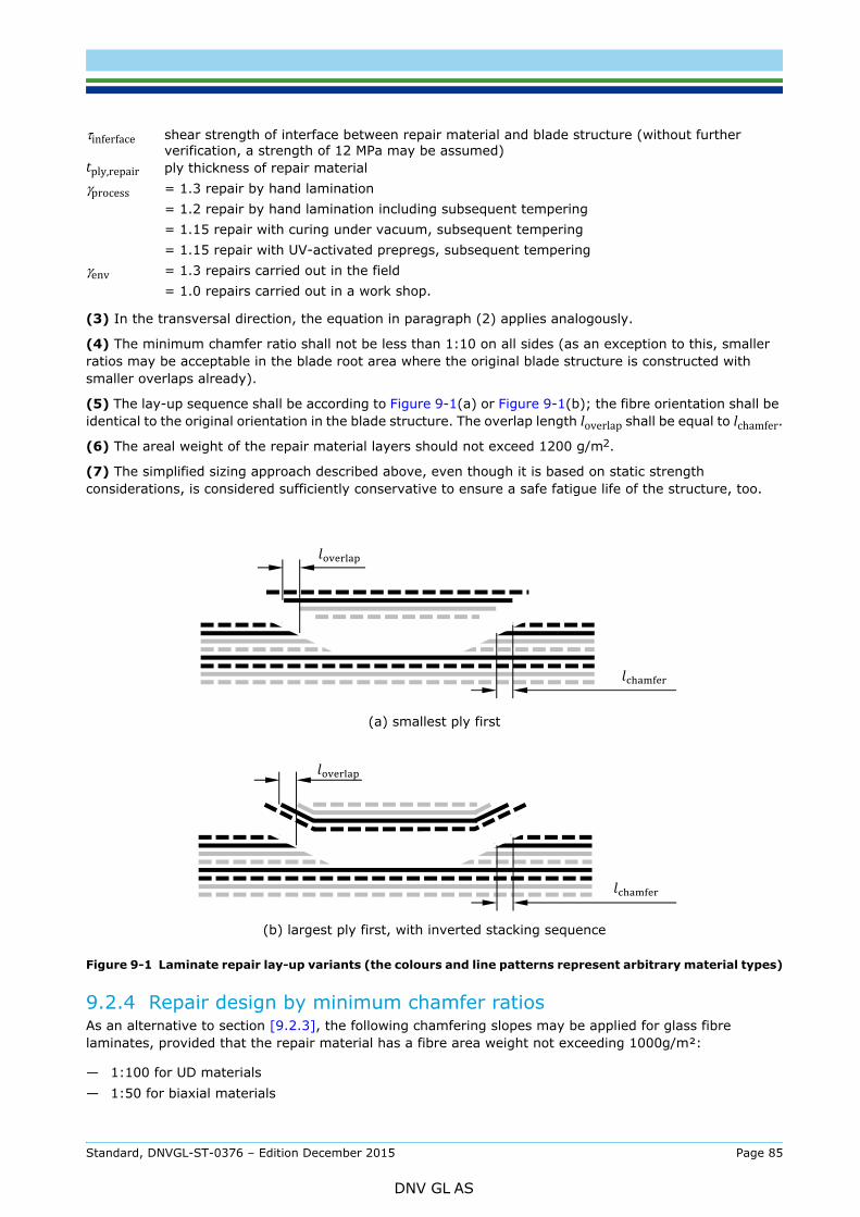
(3) In the transversal direction, the equation in paragraph (2) applies analogously.
(4) The minimum chamfer ratio shall not be less than 1:10 on all sides (as an exception to this, smaller ratios may be acceptable in the blade root area where the original blade structure is constructed with smaller overlaps already).
(5) The lay-up sequence shall be according to Figure 9-1(a) or Figure 9-1(b); the fibre orientation shall be identical to the original orientation in the blade structure. The overlap length loverlap shall be equal to lchamfer.(6) The areal weight of the repair material layers should not exceed 1200 g/m2.
(7) The simplified sizing approach described above, even though it is based on static strength considerations, is considered sufficiently conservative to ensure a safe fatigue life of the structure, too.
(a) smallest ply first
(b) largest ply first, with inverted stacking sequence
Figure 9-1 Laminate repair lay-up variants (the colours and line patterns represent arbitrary material types)
9.2.4 Repair design by minimum chamfer ratiosAs an alternative to section [9.2.3], the following chamfering slopes may be applied for glass fibre laminates, provided that the repair material has a fibre area weight not exceeding 1000g/m²:
— 1:100 for UD materials— 1:50 for biaxial materials
τinferface shear strength of interface between repair material and blade structure (without further verification, a strength of 12 MPa may be assumed)
tply,repair ply thickness of repair materialγprocess = 1.3 repair by hand lamination
= 1.2 repair by hand lamination including subsequent tempering= 1.15 repair with curing under vacuum, subsequent tempering= 1.15 repair with UV-activated prepregs, subsequent tempering
γenv = 1.3 repairs carried out in the field= 1.0 repairs carried out in a work shop.
Standard, DNVGL-ST-0376 – Edition December 2015 Page 85
DNV GL AS
determined, depending on the actual material construction (ply areal weights and orientation).
In this case, no further verification or testing is required.
9.3 Execution of repairs in a workshop and in the field
9.3.1 General(1) Repairs shall only be performed by workshops and service providers which are approved by DNV GL for the repair of wind turbine rotor blades made from fibre-reinforced thermosetting resins.
(2) This section [9.3] specifies requirements for repairs in a workshop, as well as for repairs in the field. In both cases, a separate DNV GL approval is necessary to meet the requirement as per paragraph (1) above.
(3) Repair shop approval, and approval as an in-field repair service provider, is granted by DNV GL on the basis of the information to be submitted in the relevant DNV GL approval application forms, and on the basis of the DNV GL inspection report. The application forms require information regarding the following:
— general information on the shop— personnel— quality management— incoming material inspection— material storage and handling in the shop and during field work— mechanical processing capabilities— production equipment.
(4) Any service provider carrying out repairs shall be capable to do so. It shall be ensured that the service provider has:
— up-to-date manuals for the relevant blade type— all required equipment— sufficiently qualified personnel.
Guidance note:Formal requirements may apply depending on the certification or regulatory context, including the requirement to demonstrate knowledge and quality of work with regards to the OEM’s requirements, in order to ensure and maintain the performance of the original blade and to prevent inferior practices.
---e-n-d---of---g-u-i-d-a-n-c-e---n-o-t-e---
9.3.2 Requirements for repair workshopsFor repair workshops, the requirements for workshops as specified in section 5 (manufacturing) shall apply.
9.3.3 Requirements for in-field repair service providers(1) All repairs shall be carried out by persons with proven professional knowledge. This professional knowledge shall be proven by suitable training certificates. In the absence of such certificates, sufficient professional knowledge shall be proven through a relevant, successfully completed vocational education, in connection with internal professional training and pertinent professional experience of several months.
(2) The head of the repair team is responsible for proper execution of the repair and shall be explicitly named in the shop approval. The head of the repair team shall have proven professional knowledge, which shall be proven by all of the following:
— suitable training certificates (or equivalent proof of qualification)— pertinent professional experience (including in-field repairs) of several years— demonstration during a DNV GL inspection of a repair in the field.
Standard, DNVGL-ST-0376 – Edition December 2015 Page 86
DNV GL AS
(1) Before the repair work begins, the repair specification as per section [9.2.1] should be approved by DNV GL.
(2) All damaged material, or material which no longer exhibits complete bonding, shall be removed from the area to be repaired. Any cutting or grinding operation shall be carried out in a careful and controlled manner, in order to avoid any damage to adjacent fibre plies, cores, or structures (e.g. spar cap) which are not subject to repair.
(3) It shall be verified that the materials available for the repair are in accordance with the materials specified in the repair specification. It shall be verified that all fibre and core materials are sufficiently dry, and free of contamination.
(4) The area to be repaired shall be prepared and cleaned in the following sequence:
— Before cutting or grinding, the repair area shall be cleaned from any dirt, dust or grease present at the surface, using dry or wet techniques (including solvent based liquids) as appropriate.
— After cutting / chamfering, the surface of the repair area shall be ground thoroughly, e.g. by using sandpaper with a grain of 80 or 120.
— Once all cutting, chamfering, and grinding is completed, the repair area shall be thoroughly cleaned from any dust or contamination, using dry techniques (such as brushing, vacuum cleaning, or air blasting with compressed air free of oil contamination); no wet techniques shall be applied in this cleaning step, in order to avoid clogging of surface pores or cavities with wetted dust particles.
— Only after thorough dry cleaning has been accomplished, a wet cloth may be used to clean the surface from residual dust particles; no solvent based liquid shall be used in this final cleaning step.
(5) If necessary, the laminate and the core material shall be sufficiently dried before proceeding with the repair work.
(6) As far as possible, the area to be repaired shall be relieved of any stresses caused by the blade weight. In the case of repairs performed in the field, special precautions shall be taken if necessary to prevent the occurrence of external loads (e.g. caused by vibration). Repairs of severe defects of the main load carrying components (i.e. spar cap) shall not be performed while the blade is connected to the turbine unless shown to be acceptable.
(7) The workplace shall be arranged in a way which ensures good accessibility and sufficient illumination of the area to be repaired.
(8) During repair, the affected area shall be protected against moisture and direct UV radiation as much as possible.
(9) The mixing ratio of resin and hardener shall be maintained as precisely as possible (without further proof, the relative deviation from the nominal mixing ratio shall not exceed 3% by weight for epoxy resins). The actual mixing ratio and the quantities used shall be recorded in a dosing report. For each repair, a sample of the resin/hardener mix as used during the repair shall be separated during processing, cured in the direct vicinity of the repair and under the same conditions, and archived as witness specimen.
(10) During the repair work, the ambient temperature, the blade temperature, and the relative air humidity shall be monitored by means of calibrated thermometers and hygrometers to be positioned in the vicinity of the repair area. The measured values shall not exceed the limits specified and justified with regard to the materials and processes used. If no such limits are specified, the following shall apply: The ambient temperature and the blade temperature shall be maintained between 16°C and 30°C, and the relative humidity shall not exceed 80%.
(11) The process shall ensure complete impregnation of all reinforcing materials to form a homogenous and continuously closed surface. Without further verification, a void content of 4% shall not be exceeded. All core material edges and surfaces shall be entirely sealed by resin.
(12) A final layer of low areal weight and high resin content (e.g. 225g/m2 and 30% glass weight) should be applied as sacrificial ply.
(13) The laminate and core materials shall be given suitable surface protection by means of a coating resin, preferably using the same coatings as in the original blade structure.
Standard, DNVGL-ST-0376 – Edition December 2015 Page 87
DNV GL AS
atmospheric oxygen (e.g. by adding paraffin or using foil coverings).
(15) When processing UV-activated prepregs, any requirements specified by the material suppliers shall be fulfilled regarding the following:
— material storage and material handling— maximum number of layers— surface preparation— processing parameters, including details such as size of the irradiated surface area, as well as
wavelength, energetic intensity, and duration of UV radiation.
It shall be ensured that the wet prepreg is constantly in contact with the repair area during UV curing. For each repair, a representative sample of the prepreg lay-up as used during lamination (i.e. containing the same maximum number of plies) shall be prepared during processing, cured in the direct vicinity of the repair and under the same conditions (i.e. same UV radiation), and archived as witness specimen.
(16) It shall be ensured that no changes in elongation and strain occur in the repair due to external loading on the blade during resin application and curing.
(17) Before the repaired structure is mechanically loaded or resumes operation, it shall be ensured that the thermosetting resin of the repair has sufficiently cured. This shall be achieved by monitoring the temperature during curing, Shore D hardness tests, or any other suitable method.
(18) The resin shall be cured according to specifications provided by the material supplier, or based on results from appropriate testing. In the absence of any such specifications, the following shall apply for cold-setting resin systems:
— curing for at least 72 hours, at a constant temperature of 16°C; or— curing for at least 38 hours, at a constant temperature of 25°C.
(19) In case the original blade structure was tempered during manufacturing, the repair shall also be tempered after setting, unless sufficient proof is provided that this is not necessary.
(20) In case of interruptions during the repair process, measures shall be taken to ensure an appropriate adhesion of the subsequently laminated plies.
(21) For repairs on sandwich laminates where the curing heat can only be applied from one side, separate curing steps shall be specified for inner and outer laminate.
9.3.5 Documentation(1) Upon completion of each repair, a report shall be prepared, and signed by the head of the repair team.
(2) The repair report shall at least contain:
— designation and serial number of the rotor blade— date of repair— location (address of the workshop, or location in the field)— start time of repair— description of damage (position on the rotor blade, type, size)— reference to approved repair specification— climatic conditions during repair and curing (including wind speed, if applicable)— batch number of materials used— mixing ratios for thermosetting resin systems; dosing report— lay-up, including number of layers, orientation, and overlaps — any deviations from the repair specification— duration of the repair (including repair interruptions if applicable)— curing time (or, for UV curing: wavelength, energetic intensity, and duration of radiation)— photos
Standard, DNVGL-ST-0376 – Edition December 2015 Page 88
DNV GL AS

(3) The photos attached to the report shall at least show the following:
— original damage, before any repair operation— the repair area after preparation (i.e. cutting or grinding, and cleaning), and before lamination,
illustrating the achieved chamfer dimensions and markings for overlaps— lay-up of some of the repair plies— application of resin— curing— finishing work— final result.
Standard, DNVGL-ST-0376 – Edition December 2015 Page 89
DNV GL AS
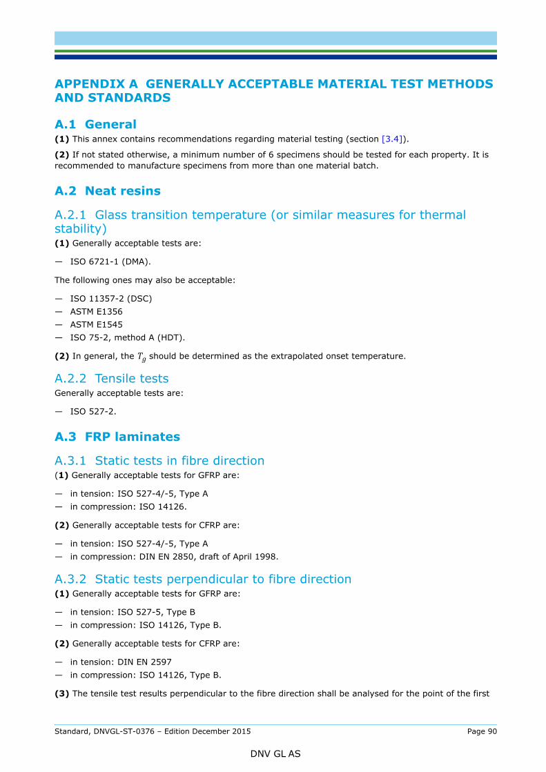
AND STANDARDS
A.1 General(1) This annex contains recommendations regarding material testing (section [3.4]).
(2) If not stated otherwise, a minimum number of 6 specimens should be tested for each property. It is recommended to manufacture specimens from more than one material batch.
A.2 Neat resins
A.2.1 Glass transition temperature (or similar measures for thermal stability)(1) Generally acceptable tests are:
— ISO 6721-1 (DMA).
The following ones may also be acceptable:
— ISO 11357-2 (DSC)— ASTM E1356— ASTM E1545— ISO 75-2, method A (HDT).
(2) In general, the Tg should be determined as the extrapolated onset temperature.
A.2.2 Tensile testsGenerally acceptable tests are:
— ISO 527-2.
A.3 FRP laminates
A.3.1 Static tests in fibre direction(1) Generally acceptable tests for GFRP are:
— in tension: ISO 527-4/-5, Type A— in compression: ISO 14126.
(2) Generally acceptable tests for CFRP are:
— in tension: ISO 527-4/-5, Type A— in compression: DIN EN 2850, draft of April 1998.
A.3.2 Static tests perpendicular to fibre direction(1) Generally acceptable tests for GFRP are:
— in tension: ISO 527-5, Type B— in compression: ISO 14126, Type B.
(2) Generally acceptable tests for CFRP are:
— in tension: DIN EN 2597— in compression: ISO 14126, Type B.
(3) The tensile test results perpendicular to the fibre direction shall be analysed for the point of the first
Standard, DNVGL-ST-0376 – Edition December 2015 Page 90
DNV GL AS
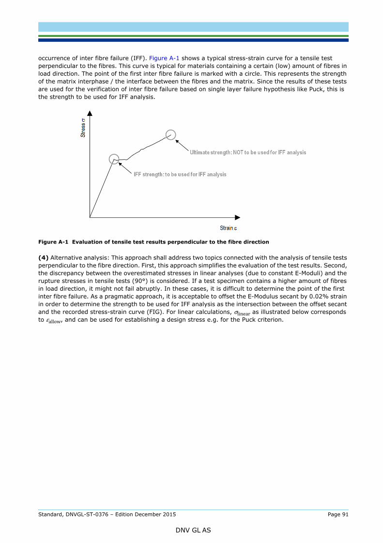
perpendicular to the fibres. This curve is typical for materials containing a certain (low) amount of fibres in load direction. The point of the first inter fibre failure is marked with a circle. This represents the strength of the matrix interphase / the interface between the fibres and the matrix. Since the results of these tests are used for the verification of inter fibre failure based on single layer failure hypothesis like Puck, this is the strength to be used for IFF analysis.
Figure A-1 Evaluation of tensile test results perpendicular to the fibre direction
(4) Alternative analysis: This approach shall address two topics connected with the analysis of tensile tests perpendicular to the fibre direction. First, this approach simplifies the evaluation of the test results. Second, the discrepancy between the overestimated stresses in linear analyses (due to constant E-Moduli) and the rupture stresses in tensile tests (90°) is considered. If a test specimen contains a higher amount of fibres in load direction, it might not fail abruptly. In these cases, it is difficult to determine the point of the first inter fibre failure. As a pragmatic approach, it is acceptable to offset the E-Modulus secant by 0.02% strain in order to determine the strength to be used for IFF analysis as the intersection between the offset secant and the recorded stress-strain curve (FIG). For linear calculations, σlinear as illustrated below corresponds to εallow, and can be used for establishing a design stress e.g. for the Puck criterion.
Standard, DNVGL-ST-0376 – Edition December 2015 Page 91
DNV GL AS
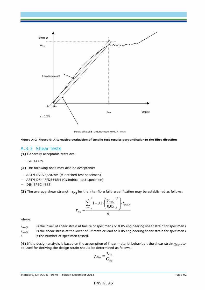
Figure A-2 Figure 9: Alternative evaluation of tensile test results perpendicular to the fibre direction
A.3.3 Shear tests(1) Generally acceptable tests are:
— ISO 14129.
(2) The following ones may also be acceptable:
— ASTM D7078/7078M (V-notched test specimen)— ASTM D5448/D5448M (Cylindrical test specimen)— DIN SPEC 4885.
(3) The average shear strength τavg for the inter fibre failure verification may be established as follows:
where:
(4) If the design analysis is based on the assumption of linear material behaviour, the shear strain γallow to be used for deriving the design strain should be determined as follows:
γeval,i is the lower of shear strain at failure of specimen i or 0.05 engineering shear strain for specimen iτeval,i is the shear stress at the lower of ultimate or load at 0.05 engineering shear strain for specimen in s the number of specimen tested.
Stress σ
Stra in ε εallow
Parallel offset of E -Modulus secant by 0.02% strain
ε = 0.02%
E -Modulus secant
σlinear
n
n
iieval
ieval
avg
=
⋅
⋅−
=1
,
2,
05.01.01 τ
γ
τ
avg
avgallow G
τγ =
Standard, DNVGL-ST-0376 – Edition December 2015 Page 92
DNV GL AS
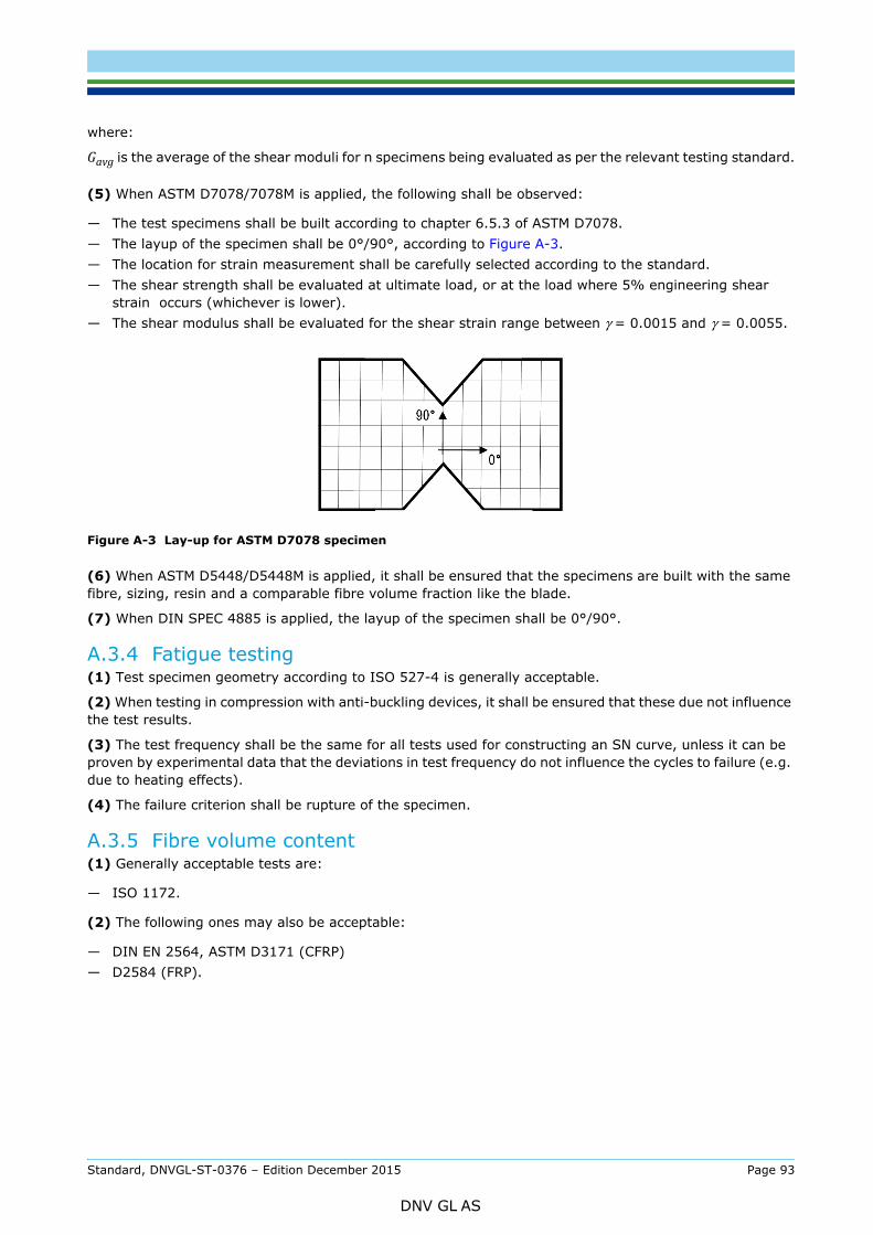
Gavg is the average of the shear moduli for n specimens being evaluated as per the relevant testing standard.
(5) When ASTM D7078/7078M is applied, the following shall be observed:
— The test specimens shall be built according to chapter 6.5.3 of ASTM D7078.— The layup of the specimen shall be 0°/90°, according to Figure A-3.— The location for strain measurement shall be carefully selected according to the standard.— The shear strength shall be evaluated at ultimate load, or at the load where 5% engineering shear
strain occurs (whichever is lower).— The shear modulus shall be evaluated for the shear strain range between γ = 0.0015 and γ = 0.0055.
Figure A-3 Lay-up for ASTM D7078 specimen
(6) When ASTM D5448/D5448M is applied, it shall be ensured that the specimens are built with the same fibre, sizing, resin and a comparable fibre volume fraction like the blade.
(7) When DIN SPEC 4885 is applied, the layup of the specimen shall be 0°/90°.
A.3.4 Fatigue testing(1) Test specimen geometry according to ISO 527-4 is generally acceptable.
(2) When testing in compression with anti-buckling devices, it shall be ensured that these due not influence the test results.
(3) The test frequency shall be the same for all tests used for constructing an SN curve, unless it can be proven by experimental data that the deviations in test frequency do not influence the cycles to failure (e.g. due to heating effects).
(4) The failure criterion shall be rupture of the specimen.
A.3.5 Fibre volume content(1) Generally acceptable tests are:
— ISO 1172.
(2) The following ones may also be acceptable:
— DIN EN 2564, ASTM D3171 (CFRP)— D2584 (FRP).
Standard, DNVGL-ST-0376 – Edition December 2015 Page 93
DNV GL AS
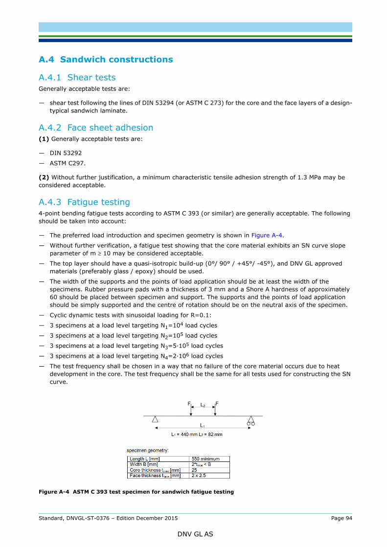
A.4.1 Shear testsGenerally acceptable tests are:
— shear test following the lines of DIN 53294 (or ASTM C 273) for the core and the face layers of a design-typical sandwich laminate.
A.4.2 Face sheet adhesion(1) Generally acceptable tests are:
— DIN 53292
— ASTM C297.
(2) Without further justification, a minimum characteristic tensile adhesion strength of 1.3 MPa may be considered acceptable.
A.4.3 Fatigue testing4-point bending fatigue tests according to ASTM C 393 (or similar) are generally acceptable. The following should be taken into account:
— The preferred load introduction and specimen geometry is shown in Figure A-4.
— Without further verification, a fatigue test showing that the core material exhibits an SN curve slope parameter of m ≥ 10 may be considered acceptable.
— The top layer should have a quasi-isotropic build-up (0°/ 90° / +45°/ -45°), and DNV GL approved materials (preferably glass / epoxy) should be used.
— The width of the supports and the points of load application should be at least the width of the specimens. Rubber pressure pads with a thickness of 3 mm and a Shore A hardness of approximately 60 should be placed between specimen and support. The supports and the points of load application should be simply supported and the centre of rotation should be on the neutral axis of the specimen.
— Cyclic dynamic tests with sinusoidal loading for R=0.1:
— 3 specimens at a load level targeting N1=104 load cycles
— 3 specimens at a load level targeting N2=105 load cycles
— 3 specimens at a load level targeting N3=5·105 load cycles
— 3 specimens at a load level targeting N4=2·106 load cycles
— The test frequency shall be chosen in a way that no failure of the core material occurs due to heat development in the core. The test frequency shall be the same for all tests used for constructing the SN curve.
Figure A-4 ASTM C 393 test specimen for sandwich fatigue testing
Standard, DNVGL-ST-0376 – Edition December 2015 Page 94
DNV GL AS

A.5.1 Neat adhesive resinSee [A.2].
A.5.2 Ultimate adhesive joint strength(1) Generally acceptable tests are:
— lap shear test on FRP substrates: ASTM D5868, ASTM D3528, EN 1465
— lap shear test on metal substrates: ASTM D1002
— peel: ISO 11339.
(2) In addition, it is strongly recommended to use test specimens that are more representative of the blade structure (i.e. component or sub-structure test specimens) for determining ultimate strength design properties in shear, peel, and axial direction.
A.5.3 Fatigue adhesive joint strength(1) For shear loading, fatigue testing may be carried out as follows:
— cyclic dynamic tests with sinusoidal loading for R=0.1
— 3 specimens at a load level targeting 104 load cycles to failure
— 3 specimens at a load level targeting 106 load cycles to failure
— 3 specimens at a load level targeting 107 load cycles to failure
— plus 3 specimens static test to failure.
(2) For this, single and double lap shear tests may be acceptable.
(3) The test frequency shall be the same for all tests used for constructing an SN curve.
(4) In addition, it is strongly recommended to use test specimens that are more representative of the blade structure (i.e. component or sub-structure test specimens) for determining fatigue strength design properties in shear, peel, and axial direction.
A.5.4 Fracture toughnessGenerally acceptable tests are:
— Mode I fracture (opening): ASTM D5528, DIN EN 6033
— Mode II fracture (shearing): End notch flexural (ENF) specimens can be used to determine the fracture properties under mode II loading [2]
— Mixed mode I + II: ASTM D 6671 (recommended because it gives a clear indication of the interaction between mode I and mode II in the strength of the adhesive joint).
A.5.5 CreepIf the design verification of an adhesive joint against creep (see section [2.5.5] (5)) is based on material creep limits, an appropriate creep test will consist of the following:
— For coupon tests according to DIN EN 1465 with 0.5 mm and 3 mm bond line thicknesses, and at a specified load applied for 192 hours, the strain in creep shall be:
— below 0.18 mm in the long-duration shear tension test for an adhesive layer thickness of 0.5 mm; and
— below 1 mm for an adhesive layer thickness of 3 mm.
— If these requirements are met, the specified load can be considered the creep limit.
Standard, DNVGL-ST-0376 – Edition December 2015 Page 95
DNV GL AS
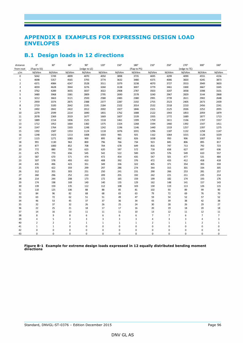
z/m0123456789
10111213141516171819202122232425262728293031323334353637383940414243
distafrom
APPENDIX B EXAMPLES FOR EXPRESSING DESIGN LOAD ENVELOPES
B.1 Design loads in 12 directions
Figure B-1 Example for extreme design loads expressed in 12 equally distributed bending moment directions
0° 30° 60° 90° 120° 150° 180° 210° 250° 270° 300° 330°(flap to SS) (edge to LE) (flap to PS) (edge to TE)
M/kNm M/kNm M/kNm M/kNm M/kNm M/kNm M/kNm M/kNm M/kNm M/kNm M/kNm M/kNm5042 5749 4899 4070 4050 3898 3735 4695 4299 4099 4555 41564698 5357 4565 3793 3774 3632 3480 4375 4006 3820 4245 38734371 4984 4247 3528 3511 3379 3238 4070 3727 3553 3949 36034059 4628 3944 3276 3260 3138 3007 3779 3461 3300 3667 33453762 4289 3655 3037 3022 2908 2787 3503 3207 3058 3398 31013480 3968 3381 2809 2795 2690 2578 3240 2967 2829 3144 28683212 3663 3121 2593 2580 2483 2380 2991 2739 2611 2902 26482959 3374 2875 2388 2377 2287 2192 2755 2523 2405 2673 24392719 3100 2642 2195 2184 2102 2014 2532 2318 2210 2456 22412492 2842 2422 2012 2002 1927 1846 2321 2125 2026 2252 20552279 2599 2214 1840 1831 1762 1688 2122 1943 1853 2059 18792078 2369 2019 1677 1669 1607 1539 1935 1772 1689 1877 17131889 2154 1836 1525 1518 1461 1399 1759 1611 1536 1707 15571712 1952 1664 1382 1375 1324 1268 1594 1460 1392 1547 14111547 1764 1503 1248 1242 1196 1146 1440 1319 1257 1397 12751392 1587 1353 1124 1118 1076 1031 1296 1187 1132 1258 11471248 1423 1213 1008 1003 965 925 1162 1064 1015 1128 10291115 1271 1083 900 895 862 826 1038 950 906 1007 919991 1130 963 800 796 766 734 923 845 806 895 817877 1000 852 708 704 678 649 816 747 713 792 723772 880 750 623 620 597 572 718 658 627 697 636675 770 656 545 542 522 500 629 576 549 610 557587 670 571 474 472 454 435 547 501 477 531 484507 578 493 410 408 392 376 472 433 412 458 418435 496 423 351 349 336 322 405 371 354 393 359370 422 359 299 297 286 274 344 315 301 334 305312 355 303 251 250 241 231 290 266 253 281 257260 296 252 210 209 201 192 242 221 211 235 214214 244 208 173 172 165 159 199 182 174 193 176174 198 169 140 140 135 129 162 148 141 157 143139 159 135 112 112 108 103 130 119 113 126 115110 125 106 88 88 85 81 102 93 89 99 9084 96 82 68 68 65 63 79 72 69 76 7063 72 62 51 51 49 47 59 54 52 57 5246 53 45 37 37 36 34 43 39 38 42 3832 37 32 26 26 25 24 30 28 26 29 2722 25 21 18 17 17 16 20 19 18 20 1814 16 13 11 11 11 10 13 12 11 12 118 9 8 6 6 6 6 7 7 6 7 74 5 4 3 3 3 3 4 3 3 4 32 2 2 1 1 1 1 2 1 1 2 11 1 0 0 0 0 0 0 0 0 0 00 0 0 0 0 0 0 0 0 0 0 00 0 0 0 0 0 0 0 0 0 0 0
nceroot
Standard, DNVGL-ST-0376 – Edition December 2015 Page 96
DNV GL AS
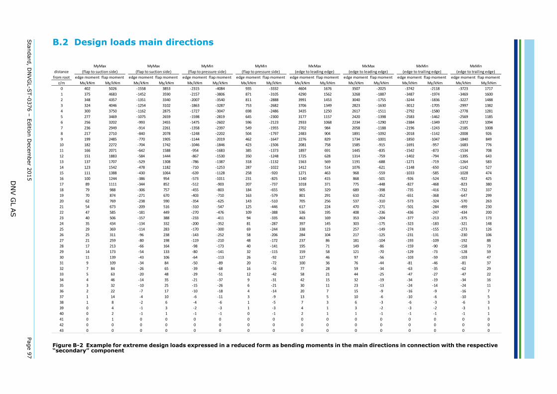
Standard, D
NVG
L-ST-0376 – Edition D
ecember 2015
Page 97
DN
V G
L A
S
B.2 Design loads main directions
directions in connection with the respective
nt flap moment edge moment flap moment edge moment flap momentMy/kNm Mx/kNm My/kNm Mx/kNm My/kNm
-2025 -3742 -2118 -3723 1717-1887 -3487 -1974 -3469 1600-1755 -3244 -1836 -3227 1488-1630 -3012 -1705 -2997 1382-1511 -2792 -1580 -2778 1281-1398 -2583 -1462 -2569 1185-1290 -2384 -1349 -2372 1094-1188 -2196 -1243 -2185 1008-1092 -2018 -1142 -2008 926-1001 -1850 -1047 -1840 849-915 -1691 -957 -1683 776-835 -1542 -873 -1534 708-759 -1402 -794 -1395 643-688 -1271 -719 -1264 583-621 -1148 -650 -1142 527-559 -1033 -585 -1028 474-501 -926 -524 -922 425-448 -827 -468 -823 380-398 -735 -416 -732 337-352 -651 -368 -647 299-310 -573 -324 -570 263-271 -501 -284 -499 230-236 -436 -247 -434 200-204 -377 -213 -375 173-175 -323 -183 -321 148-149 -274 -155 -273 126-125 -231 -131 -230 106-104 -193 -109 -192 88-86 -159 -90 -158 73-70 -129 -73 -128 59-56 -103 -59 -103 47-44 -81 -46 -81 37-34 -63 -35 -62 29-25 -47 -27 -47 22-19 -34 -19 -34 16-13 -24 -14 -24 11-9 -16 -9 -16 7-6 -10 -6 -10 5-3 -6 -3 -6 3-2 -3 -2 -3 1-1 -1 -1 -1 10 0 0 0 00 0 0 0 00 0 0 0 0
MxMin(edge to trailing edge)
MxMin(edge to trailing edge)
xMaxleading edge)
Figure B-2 Example for extreme design loads expressed in a reduced form as bending moments in the main“secondary” component
edge moment flap moment edge moment flap moment edge moment flap moment edge moment flap moment edge moment flap moment edge momez/m Mx/kNm My/kNm Mx/kNm My/kNm Mx/kNm My/kNm Mx/kNm My/kNm Mx/kNm My/kNm Mx/kNm
0 402 5026 -1558 3853 -2315 -4084 935 -3332 4604 1676 35071 375 4683 -1452 3590 -2157 -3806 871 -3105 4290 1562 32682 348 4357 -1351 3340 -2007 -3540 811 -2888 3991 1453 30403 324 4046 -1254 3102 -1863 -3287 753 -2682 3706 1349 28234 300 3750 -1162 2875 -1727 -3047 698 -2486 3435 1250 26175 277 3469 -1075 2659 -1598 -2819 645 -2300 3177 1157 24206 256 3202 -993 2455 -1475 -2602 596 -2123 2933 1068 22347 236 2949 -914 2261 -1358 -2397 549 -1955 2702 984 20588 217 2710 -840 2078 -1248 -2202 504 -1797 2483 904 18919 199 2485 -770 1905 -1144 -2019 462 -1647 2276 829 1734
10 182 2272 -704 1742 -1046 -1846 423 -1506 2081 758 158511 166 2071 -642 1588 -954 -1683 385 -1373 1897 691 144512 151 1883 -584 1444 -867 -1530 350 -1248 1725 628 131413 137 1707 -529 1308 -786 -1387 318 -1132 1563 569 119114 123 1542 -478 1182 -710 -1253 287 -1022 1412 514 107615 111 1388 -430 1064 -639 -1128 258 -920 1271 463 96816 100 1244 -386 954 -573 -1011 231 -825 1140 415 86817 89 1111 -344 852 -512 -903 207 -737 1018 371 77518 79 988 -306 757 -455 -803 184 -655 905 329 68919 70 874 -271 670 -403 -710 163 -579 801 291 61020 62 769 -238 590 -354 -625 143 -510 705 256 53721 54 673 -209 516 -310 -547 125 -446 617 224 47022 47 585 -181 449 -270 -476 109 -388 536 195 40823 40 506 -157 388 -233 -411 94 -335 463 169 35324 35 434 -134 332 -200 -352 81 -287 397 145 30325 29 369 -114 283 -170 -300 69 -244 338 123 25726 25 311 -96 238 -143 -252 58 -206 284 104 21727 21 259 -80 198 -119 -210 48 -172 237 86 18128 17 213 -66 164 -98 -173 40 -141 195 71 14929 14 173 -54 133 -80 -141 32 -115 159 58 12130 11 139 -43 106 -64 -113 26 -92 127 46 9731 9 109 -34 84 -50 -89 20 -72 100 36 7632 7 84 -26 65 -39 -68 16 -56 77 28 5933 5 63 -20 48 -29 -51 12 -42 58 21 4434 4 46 -14 35 -21 -37 9 -31 42 15 3235 3 32 -10 25 -15 -26 6 -21 30 11 2336 2 22 -7 17 -10 -18 4 -14 20 7 1537 1 14 -4 10 -6 -11 3 -9 13 5 1038 1 8 -2 6 -4 -6 1 -5 7 3 639 0 4 -1 3 -2 -3 1 -3 4 1 340 0 2 -1 1 -1 -1 0 -1 2 1 141 0 1 0 0 0 0 0 0 0 0 042 0 0 0 0 0 0 0 0 0 0 043 0 0 0 0 0 0 0 0 0 0 0
MxMax(edge to leading edge)
M(edge to distance
from root
MyMax(flap to suction side)
MyMax(flap to suction side)
MyMin(flap to pressure side)
MyMin(flap to pressure side)
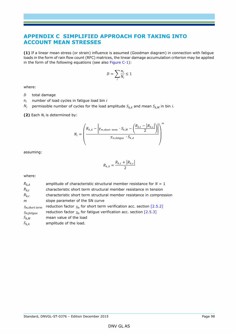
ACCOUNT MEAN STRESSES
(1) If a linear mean stress (or strain) influence is assumed (Goodman diagram) in connection with fatigue loads in the form of rain flow count (RFC) matrices, the linear damage accumulation criterion may be applied in the form of the following equations (see also Figure C-1):
where:
(2) Each Ni is determined by:
assuming:
where:
D total damageni number of load cycles in fatigue load bin iNi permissible number of cycles for the load amplitude Sk,A and mean Sk,M in bin i.
Rk,A amplitude of characteristic structural member resistance for N = 1Rk,t characteristic short term structural member resistance in tensionRk,c characteristic short term structural member resistance in compressionm slope parameter of the SN curveγm,short term reduction factor γm for short term verification acc. section [2.5.2]γm,fatigue reduction factor γm for fatigue verification acc. section [2.5.3]Sk,M mean value of the loadSk,A amplitude of the load.
= ≤ 1
= , − ,short term ∙ , − , − ,2,fatigue ∙ ,
, = , + ,2
Standard, DNVGL-ST-0376 – Edition December 2015 Page 98
DNV GL AS
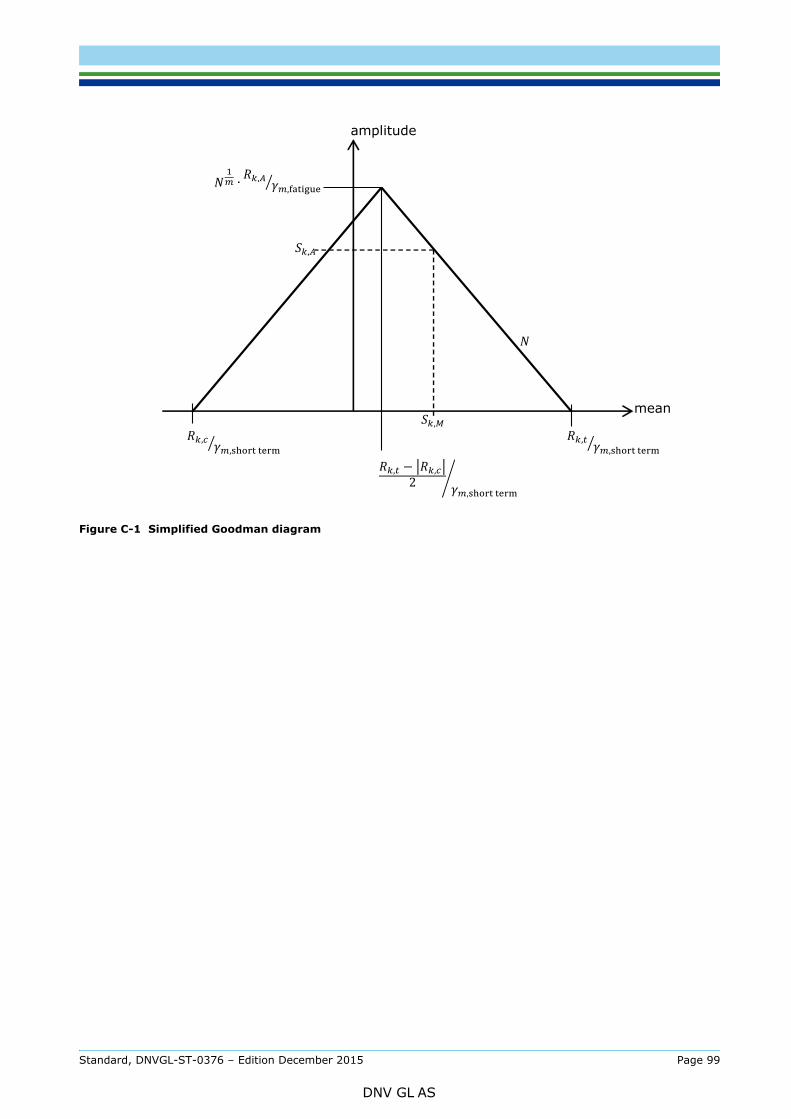
Figure C-1 Simplified Goodman diagram
,, − ,2 ,
, , , ,
∙ , ,
,
mean
amplitude
Standard, DNVGL-ST-0376 – Edition December 2015 Page 99
DNV GL AS

BOLTED CONNECTIONS
(1) The following tests are required:
— The tests shall be carried out as full scale tests, and the geometry of the surrounding laminates shall be representative for the relevant blade root connection.
— Static tensile tests with a minimum of 5 specimensNote: It is advisable to design the test specimens such that the ultimate failure mode is insert pull-out rather than bolt failure (e.g. by choosing an adequately strong bolt).
— Cyclic dynamic tests with sinusoidal loading for R=0.1:
- 4 specimens at a load level targeting N1=104 load cycles- 4 specimens at a load level targeting N2=105 load cycles- 4 specimens at a load level targeting N3=2·106 load cycles- 3 specimens at a load level targeting N4=107 load cycles
— The resistance of the adhesive joint (and the effectiveness of protection measures, if any) against environmental climate shall be proven separately.
— The test frequency shall be the same for all tests used for constructing the SN curve.
(2) The interpolation of test results to different geometries of the insert (e.g. diameter, length) is generally not allowed.
(3) It is advisable to design the test specimens such that the ultimate failure mode is insert pull-out rather than bolt failure (e.g. by choosing an adequately strong bolt).
Standard, DNVGL-ST-0376 – Edition December 2015 Page 100
DNV GL AS
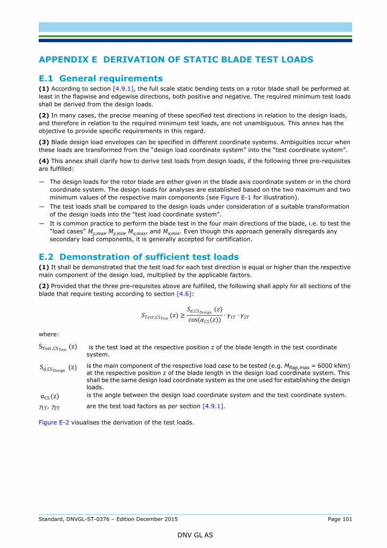
E.1 General requirements(1) According to section [4.9.1], the full scale static bending tests on a rotor blade shall be performed at least in the flapwise and edgewise directions, both positive and negative. The required minimum test loads shall be derived from the design loads.
(2) In many cases, the precise meaning of these specified test directions in relation to the design loads, and therefore in relation to the required minimum test loads, are not unambiguous. This annex has the objective to provide specific requirements in this regard.
(3) Blade design load envelopes can be specified in different coordinate systems. Ambiguities occur when these loads are transformed from the “design load coordinate system” into the “test coordinate system”.
(4) This annex shall clarify how to derive test loads from design loads, if the following three pre-requisites are fulfilled:
— The design loads for the rotor blade are either given in the blade axis coordinate system or in the chord coordinate system. The design loads for analyses are established based on the two maximum and two minimum values of the respective main components (see Figure E-1 for illustration).
— The test loads shall be compared to the design loads under consideration of a suitable transformation of the design loads into the “test load coordinate system”.
— It is common practice to perform the blade test in the four main directions of the blade, i.e. to test the “load cases” My,max, My,min, Mx,max, and Mx,min. Even though this approach generally disregards any secondary load components, it is generally accepted for certification.
E.2 Demonstration of sufficient test loads(1) It shall be demonstrated that the test load for each test direction is equal or higher than the respective main component of the design load, multiplied by the applicable factors.
(2) Provided that the three pre-requisites above are fulfilled, the following shall apply for all sections of the blade that require testing according to section [4.6]:
where:
Figure E-2 visualises the derivation of the test loads.
is the test load at the respective position z of the blade length in the test coordinate system.
is the main component of the respective load case to be tested (e.g. Mflap,max = 6000 kNm) at the respective position z of the blade length in the design load coordinate system. This shall be the same design load coordinate system as the one used for establishing the design loads.is the angle between the design load coordinate system and the test coordinate system.
γ1T, γ2T are the test load factors as per section [4.9.1].
, ( ) ≥ , ( )cos( ( )) ∙ 1 ∙ 2
STest ,CS Test (z) Sd,CS Design (z) αCS (z)
Standard, DNVGL-ST-0376 – Edition December 2015 Page 101
DNV GL AS
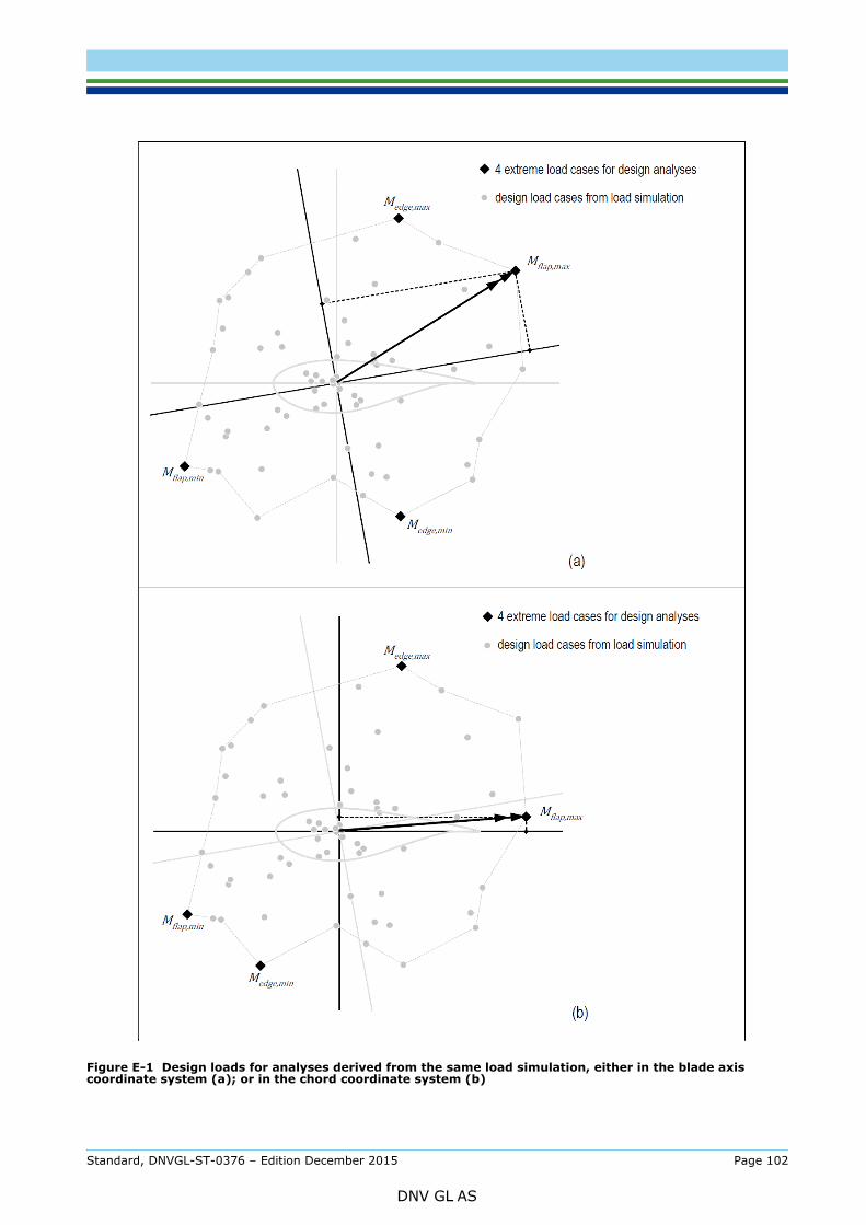
Figure E-1 Design loads for analyses derived from the same load simulation, either in the blade axis coordinate system (a); or in the chord coordinate system (b)
Standard, DNVGL-ST-0376 – Edition December 2015 Page 102
DNV GL AS
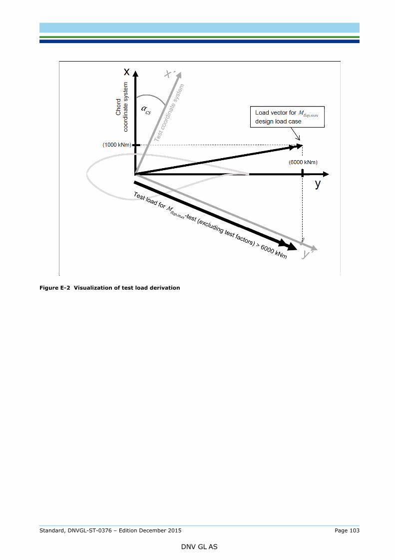
Figure E-2 Visualization of test load derivation
Standard, DNVGL-ST-0376 – Edition December 2015 Page 103
DNV GL AS
This annex contains an indicative list of documents which are generally required to be submitted for certification.
F.1 Documents for design basis evaluation— design basis report as per section [2.1.1] (2).
F.2 Documents for materials— list of materials— material datasheets— material qualification documents— material test specifications (including specimen preparation) and test results, if applicable— material design values.
F.3 Documents for design— fibre failure analyses as per section [2.5.2] and [2.5.3].— stability analyses as per section [2.5.4]— adhesive analyses as per section [2.5.5]— blade root analyses as per section [2.5.6]— deflection analyses as per section [2.5.11]— inter fibre failure analyses as per section [2.5.13]— load specification including design loads for extreme and fatigue — specification of load coordinate system— contour specification as per section [2.4.6]— assembly drawings, layup drawings, blade root drawings— blade specification including geometry details such as twist, chord length, mass distribution, stiffness
distribution, natural frequencies, total mass, centre of gravity— specification of bonded connections— specification of production sequence, and method— specification of tolerances— blade bolt drawings and specifications— metal insert drawings and specification— metal inserts: component test specification or test results— documentation regarding sub-component testing as per section [2.5.16]— specification of tightening method for blade root connection— specification of special blade features— corrosion protection specifications— specification of the lightning protection— specification of the leading edge protection against erosion— manuals and further documentation as per section [2.4.10].
F.4 Documents for blade testing— blade test specification as per section [4.3]— test blade manufacturing records as per section [4.2.2]— blade test report as per section [4.13]
Standard, DNVGL-ST-0376 – Edition December 2015 Page 104
DNV GL AS
F.5 Documents for manufacturing(1) For manufacturing evaluation (typically as part of component or type certification):
— production plan
— work instructions
— drawings
— quality procedures and quality control sheets
— list of materials
— ISO 9001:2008 or later certificate, if applicable.
(2) For manufacturing surveillance (typically as part of a project certification):
— Type certificate and the therein referenced blade reports
— Inspection and test plan (ITP). The ITP shall be provided as a table including the following information:
— all relevant production steps and the corresponding production documents, e.g. drawings, instructions, checklists and specifications.
— the responsible person for each production step
— In agreement with DNV GL the inspecting party shall be defined.
— In agreement with DNV GL the inspection scope for each production step shall be defined, e.g. witnessing, hold point, review of documentation or testing.
— The following documents shall be provided in the revision that will be used in production for this project:
— all documents referenced in the ITP
— general arrangement drawings and specifications
— manufacturing drawings, specifications and work instructions
— inspection check sheets, NDT reports, and measurements reports
— list of materials
— If the documents used for the current project differ from the documents referenced in the Type Certificate, all modifications have to be listed and explained.
— ISO 9001 certificate
— As an alternative to the ISO9001 certificate, the following documents shall be provided
— QM handbook / manual
— QM procedures
— QM work instructions
— Qualification matrix of workshop employees.
F.6 Handling, transport, installationFor reviewing the handling and transportation procedures and installation, as well as the support structures, in order to verify that the design envelope is not exceeded and that the blades are not damaged during transportation:
— blade design analyses for transport and handling conditions
— drawings of the blade transport and support devices
— specification of loads during transport including offshore transport (e.g. accelerations)
— instructions for handling, transport, and installation of blades.
Standard, DNVGL-ST-0376 – Edition December 2015 Page 105
DNV GL AS
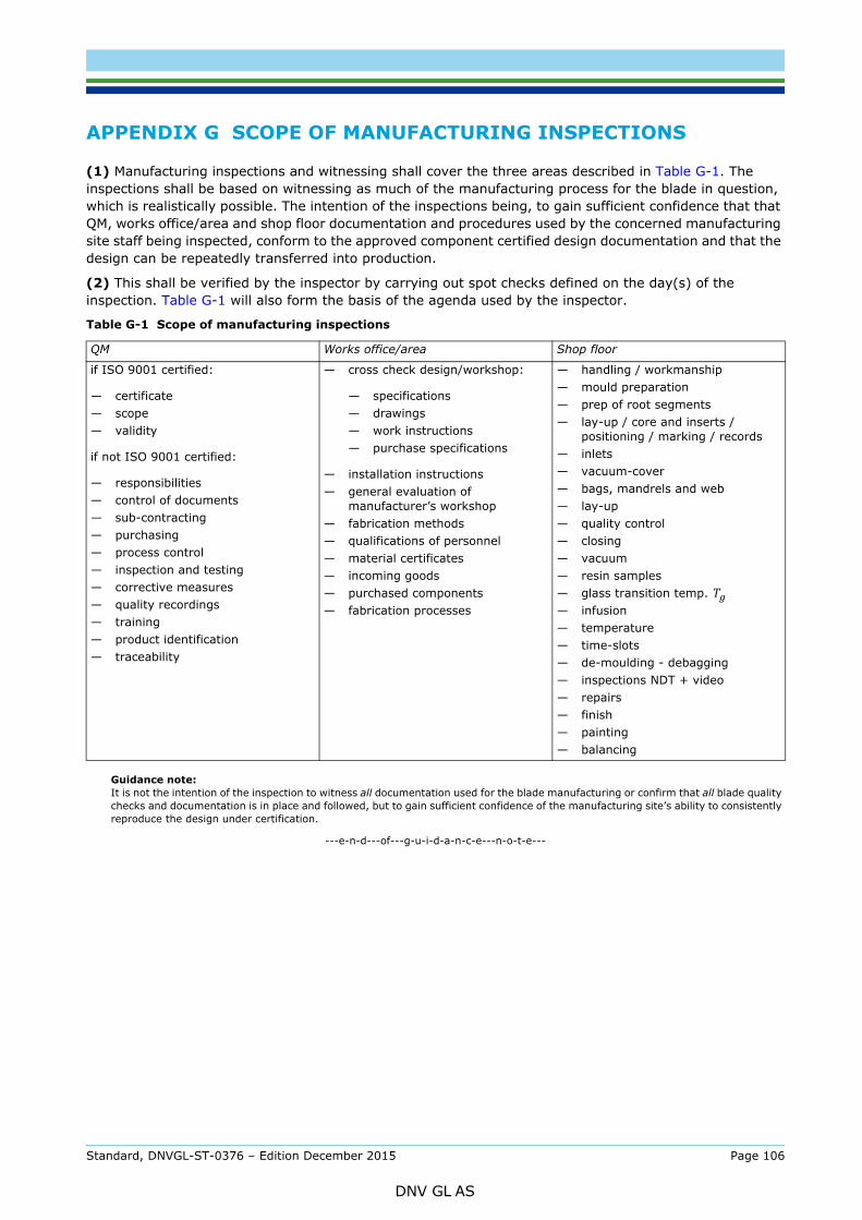
(1) Manufacturing inspections and witnessing shall cover the three areas described in Table G-1. The inspections shall be based on witnessing as much of the manufacturing process for the blade in question, which is realistically possible. The intention of the inspections being, to gain sufficient confidence that that QM, works office/area and shop floor documentation and procedures used by the concerned manufacturing site staff being inspected, conform to the approved component certified design documentation and that the design can be repeatedly transferred into production.
(2) This shall be verified by the inspector by carrying out spot checks defined on the day(s) of the inspection. Table G-1 will also form the basis of the agenda used by the inspector.
Guidance note:It is not the intention of the inspection to witness all documentation used for the blade manufacturing or confirm that all blade quality checks and documentation is in place and followed, but to gain sufficient confidence of the manufacturing site’s ability to consistently reproduce the design under certification.
---e-n-d---of---g-u-i-d-a-n-c-e---n-o-t-e---
Table G-1 Scope of manufacturing inspections
QM Works office/area Shop floor
if ISO 9001 certified:
— certificate— scope— validity
if not ISO 9001 certified:
— responsibilities— control of documents— sub-contracting— purchasing— process control— inspection and testing— corrective measures— quality recordings— training— product identification— traceability
— cross check design/workshop:
— specifications— drawings— work instructions— purchase specifications
— installation instructions— general evaluation of
manufacturer’s workshop— fabrication methods— qualifications of personnel— material certificates— incoming goods— purchased components— fabrication processes
— handling / workmanship— mould preparation— prep of root segments— lay-up / core and inserts /
positioning / marking / records— inlets— vacuum-cover— bags, mandrels and web— lay-up— quality control— closing— vacuum— resin samples— glass transition temp. Tg— infusion— temperature— time-slots— de-moulding - debagging— inspections NDT + video— repairs— finish— painting— balancing
Standard, DNVGL-ST-0376 – Edition December 2015 Page 106
DNV GL AS

SAF
DNV GLDriven by our purpose of safeguarding life, property and the environment, DNV GL enables organizations to advance the safety and sustainability of their business. We provide classification and technical assurance along with software and independent expert advisory services to the maritime, oil and gas, and energy industries. We also provide certification services to customers across a wide range of industries. Operating in more than 100 countries, our 16 000 professionals are dedicated to helping our customers make the world safer, smarter and greener.
ER, SMARTER, GREENER