dnvgl-ru-naval-pt3ch2 propulsion plants
TRANSCRIPT

The content of this service document is the subject of intellectual property rights reserved by DNV GL AS ("DNV GL"). The useraccepts that it is prohibited by anyone else but DNV GL and/or its licensees to offer and/or perform classification, certificationand/or verification services, including the issuance of certificates and/or declarations of conformity, wholly or partly, on thebasis of and/or pursuant to this document whether free of charge or chargeable, without DNV GL's prior written consent.DNV GL is not responsible for the consequences arising from any use of this document by others.
The electronic pdf version of this document, available free of chargefrom http://www.dnvgl.com, is the officially binding version.
DNV GL AS
RULES FOR CLASSIFICATION
Naval vesselsEdition December 2015
Part 3 Surface ships
Chapter 2 Propulsion plants

FOREWORD
DNV GL rules for classification contain procedural and technical requirements related to obtainingand retaining a class certificate. The rules represent all requirements adopted by the Society asbasis for classification.
© DNV GL AS December 2015
Any comments may be sent by e-mail to [email protected]
If any person suffers loss or damage which is proved to have been caused by any negligent act or omission of DNV GL, then DNV GL shallpay compensation to such person for his proved direct loss or damage. However, the compensation shall not exceed an amount equal to tentimes the fee charged for the service in question, provided that the maximum compensation shall never exceed USD 2 million.
In this provision "DNV GL" shall mean DNV GL AS, its direct and indirect owners as well as all its affiliates, subsidiaries, directors, officers,employees, agents and any other acting on behalf of DNV GL.

Part
3 C
hapt
er 2
Cha
nges
- c
urre
nt
Rules for classification: Naval vessels — DNVGL-RU-NAVAL-Pt3Ch2. Edition December 2015 Page 3Propulsion plants
DNV GL AS
CURRENT – CHANGES
This is a new document.
The rules enter into force 1 July 2016.

Part
3 C
hapt
er 2
Con
tent
s
Rules for classification: Naval vessels — DNVGL-RU-NAVAL-Pt3Ch2. Edition December 2015 Page 4Propulsion plants
DNV GL AS
CONTENTS
Current – changes...................................................................................................... 3
Section 1 General rules and instructions....................................................................71 General................................................................................................... 72 Definitions.............................................................................................. 93 Documents for approval....................................................................... 114 Ambient conditions............................................................................... 125 Materials............................................................................................... 206 Fuels and consumables for operation................................................... 217 Safety equipment and protective measures..........................................218 Survivability..........................................................................................23
Section 2 Design and construction of the machinery installation..............................251 General................................................................................................. 252 Dimensions of components...................................................................253 Availability of machinery...................................................................... 274 Control and regulating..........................................................................275 Propulsion plant................................................................................... 276 Turning appliances............................................................................... 327 Operating and maintenance instructions.............................................. 328 Markings, identification........................................................................ 329 Engine room equipment........................................................................3310 Communication and signalling equipment...........................................3411 Redundant systems............................................................................ 34
Section 3 Internal combustion engines.................................................................... 361 General................................................................................................. 362 Documents for approval....................................................................... 383 Crankshaft calculation.......................................................................... 414 Materials............................................................................................... 415 Tests and trials.....................................................................................446 Safety devices.......................................................................................537 Auxiliary systems................................................................................. 598 Control equipment................................................................................ 629 Alarms.................................................................................................. 6310 Engine alignment/seating...................................................................64

Part
3 C
hapt
er 2
Con
tent
s
Rules for classification: Naval vessels — DNVGL-RU-NAVAL-Pt3Ch2. Edition December 2015 Page 5Propulsion plants
DNV GL AS
11 Exhaust gas cleaning systems............................................................ 65
Section 4 Thermal turbomachinery gas turbines...................................................... 681 General................................................................................................. 682 Materials............................................................................................... 713 Design and construction....................................................................... 724 Control and monitoring.........................................................................765 Arrangement and installation............................................................... 796 Tests and trials.....................................................................................80
Section 5 Thermal turbomachinery / exhaust gas turbochargers............................. 861 General................................................................................................. 862 Design and installation......................................................................... 863 Tests..................................................................................................... 874 Shop approvals..................................................................................... 91
Section 6 Main shafting............................................................................................921 General................................................................................................. 922 Materials............................................................................................... 933 Shaft dimensioning...............................................................................934 Design...................................................................................................975 Balancing and testing......................................................................... 1046 Special requirements for fibre laminate shafts................................... 105
Section 7 Gears, couplings..................................................................................... 1071 General............................................................................................... 1072 Materials............................................................................................. 1073 Calculation of the load-bearing capacity of gear teeth........................ 1084 Gear shafts......................................................................................... 1165 Equipment...........................................................................................1176 Balancing and testing......................................................................... 1187 Design and construction of couplings................................................. 120
Section 8 Propulsors.............................................................................................. 1251 General............................................................................................... 1252 Materials............................................................................................. 1263 Design and dimensioning of propellers...............................................1284 Controllable pitch propellers...............................................................1345 Propeller mounting............................................................................. 1386 Balancing and testing......................................................................... 140

Part
3 C
hapt
er 2
Con
tent
s
Rules for classification: Naval vessels — DNVGL-RU-NAVAL-Pt3Ch2. Edition December 2015 Page 6Propulsion plants
DNV GL AS
7 Lateral thrust units.............................................................................1418 Special forms of propulsion systems.................................................. 1429 Dynamic positioning systems..............................................................14410 Cavitation noise of propellers........................................................... 144
Section 9 Azimuthing propulsors............................................................................1471 General............................................................................................... 1472 Materials............................................................................................. 1493 Design of azimuthing propulsors........................................................ 1494 Design of steering device................................................................... 1525 Auxiliary equipment............................................................................1576 Hydraulic systems...............................................................................1587 Electrical installations.........................................................................1598 Testing and trials................................................................................162
Section 10 Torsional vibrations.............................................................................. 1671 General............................................................................................... 1672 Calculation of torsional vibrations...................................................... 1673 Permissible torsional vibration stresses............................................. 1684 Torsional vibration measurements......................................................1745 Prohibited ranges of operation........................................................... 1746 Auxiliary machinery............................................................................ 175
Section 11 Intentionally left blank......................................................................... 1761 Intentionally left blank....................................................................... 176
Section 12 Spare parts...........................................................................................1771 General............................................................................................... 1772 Volume of Spare Parts........................................................................177
Section 13 Special requirements of the naval ship code.........................................1831 General............................................................................................... 1832 Performance requirements of Chapter IV........................................... 183
Part
3 C
hapt
er 2
Sec
tion
1
Rules for classification: Naval vessels — DNVGL-RU-NAVAL-Pt3Ch2. Edition December 2015 Page 7Propulsion plants
DNV GL AS
SECTION 1 GENERAL RULES AND INSTRUCTIONS
1 General
1.1 These rules apply to the propulsion plant of seagoing surface ships and craft intended for naval activities.The following types of propulsion plants are not included in these rules:
— nuclear power plants— plants with fuel cell technology 1
— steam boilers for main propulsion— steam turbines— low speed diesel engines with crossheads— reversible two-stroke diesel engines— plants for operation with heavy fuel oil and its pre-treatment— thermal oil systems
However, on application, plants of a type listed above may be included in a design review and classificationprocedure, where relevant for the overall concept of a naval project.
1.2 Apart from machinery and equipment detailed below, these rules are also applicable individually to othermachinery and equipment where this is necessary for the safety of the ship and its crew.
1.3 Designs which deviate from these rules may be approved, provided that such designs have been recognizedas equivalent.
1.4 Machinery installations which have been developed on novel principles and/or which have not yet beensufficiently tested in shipboard service require special approval of the Society.
1.5 In the instances mentioned in [1.3] and [1.4] the Society is entitled to require additional documentation tobe submitted and special trials to be carried out.
1.6 In addition to these rules, the Society reserves the right to impose further requirements in respect of alltypes of machinery where this is unavoidable due to new findings or operational experience, or the Societymay permit deviations from the rules where these are specially warranted.
1 For auxiliary power to be produced with fuel cell technology see RU SHIP Pt.6 Ch.2 Sec.3.

Part
3 C
hapt
er 2
Sec
tion
1
Rules for classification: Naval vessels — DNVGL-RU-NAVAL-Pt3Ch2. Edition December 2015 Page 8Propulsion plants
DNV GL AS
1.7 Reference to further regulations and standards
1.7.1 If the requirements for propulsion plants and operating agents are not defined in these rules, theapplication of other regulations and standards has to be defined as far as necessary.
1.7.2 The regulations of the "International Convention for the Safety of Life at Sea 1974/1978" (SOLAS), asamended are considered in these rules as far as they appear to be applicable to naval surface combat ships.The definite scope of application has to be defined in the building specification by the naval administrationand the shipyard.These rules are also in compliance with the provisions of the "International Convention for the Prevention ofPollution from Ships" of 1973 and the relevant Protocol of 1978 (MARPOL 73/78).
1.7.3 For ships of NATO states the Nato Agreement for Standardisation (STANAG) may be considered besidesClassification by the Society.NATO and Partners for Peace Navies may adopt in addition the Naval Ship Code which provides a frameworkfor a naval surface ship safety management system. On request the Society is prepared to check if thisCode is applied for the naval ship to be classified and to assign the class notation NSC(Chapter) in case ofsuccessful examination of the requirements of the defined Chapter(s). The detailed requirements relevant forthis Chapter are summarized in Sec.13.
1.7.4 Besides of these rules national regulations, international standards and special definitions in thebuilding specification respectively in the mission statement of the actual ship have to be considered. Theapplication of such regulations is not affected by the Society's rules.
1.8 DesignThe design of the propulsion plant has to fulfil the following conditions:
1.8.1 The operation of the naval ship and the habitual conditions provided on board as well as thefunctioning of all systems under the operational conditions of combat, wartime cruising, peacetime cruisingand in-port readiness are to be ensured at all times.
1.8.2 The power distribution network shall be designed to ensure operational availability in case of networkfailure.
1.8.3 The operation of certain systems and equipment, which are necessary for safety, is to be guaranteedunder defined emergency conditions.
1.8.4 The risks for crew and ship from operation of the propulsion plant shall be minimized.
1.8.5 High working reliability shall be achieved by simple and clearly arranged operation processes as well asby application of type-approved products.
1.8.6 The requirements concerning design, arrangement, installation and operation which are defined in theSociety's rules for Classification and Surveys Pt.1 Ch.1, Electrical Installations Ch.3, Automation Ch.4 andShip Operation Installations and Auxiliary Systems Ch.5, shall be fulfilled.
1.8.7 A high degree of survivability of the ship should be achieved by redundancies in the design andfunctioning of essential equipment.
1.8.8 The principles of ergonomic design of machinery and equipment have to be considered.

Part
3 C
hapt
er 2
Sec
tion
1
Rules for classification: Naval vessels — DNVGL-RU-NAVAL-Pt3Ch2. Edition December 2015 Page 9Propulsion plants
DNV GL AS
1.8.9 Where in a class of naval ships, originally planned to be identical, deviations become necessary, theSociety shall be duly informed and changes properly documented.
1.8.10 One failure principleThe single failure concept assumes that only one (single) failure is the initiating event for an undesiredoccurrence. The simultaneous occurrence of independent failures is not considered.
2 Definitions
2.1 Auxiliary electrical powerThe auxiliary electrical power [kVA] is defined as the continuous electrical power at continuous speedv0, which is not directly used for propulsion of the ship, but for driving all kinds of auxiliary devices andequipment. The degree of redundancy shall be defined in the building specification.
2.2 Black-out conditionBlack-out condition means that the complete machinery plant including the main source of electrical powerare out of operation, but auxiliary energy as compressed air, starting current from batteries, etc. are stillavailable for restoration of power supply.
2.3 Dead ship condition"Dead ship" condition means that the complete machinery plant including the main source of electrical powerare out of operation and auxiliary energy as compressed air, starting current from batteries, etc. are notavailable for the restoration of the main power supply, for the restart of the auxiliaries and for the start-upof the propulsion plant. It is however assumed that special mobile or fixed equipment for start-up will beavailable on board of a naval ship.
2.4 Draught TThe draught T is the vertical distance at the middle of the length L, from base line to the deepest designwater line, as estimated for the lifetime of the ship.
2.5 Essential equipment
2.5.1 Essential for ship operation are all main propulsion plants.
2.5.2 Essential (operationally important) are the following auxiliary machinery and plants, which:
— are necessary for propulsion and manoeuvrability of the ship— are required for maintaining ship safety— are required to maintain the safety of human life at sea
as well as
— equipment according to characters of classification and class notations
2.5.3 Essential auxiliary machinery and plants are comprising e.g.:
— generator units— steering gear plant— fuel oil supply units— lubricating oil pumps

Part
3 C
hapt
er 2
Sec
tion
1
Rules for classification: Naval vessels — DNVGL-RU-NAVAL-Pt3Ch2. Edition December 2015 Page 10Propulsion plants
DNV GL AS
— cooling water/cooling media pumps— starting and control-air compressor— starting installations for auxiliary and main engines— charging air blowers— exhaust gas turbochargers— controllable pitch propeller installation— azimuth drives— engine room ventilation fans— steam, hot and warm water generation plants— oil firing equipment— pressure vessels and heat exchangers in essential systems— hydraulic pumps— fuel oil treatment units— fuel oil transfer pumps— lubrication oil treatment units— bilge and ballast pumps— heeling compensation systems— fire pumps and fire fighting equipment— anchor windlasses and capstans— transverse thrusters— ventilation fans for hazardous areas— turning gears for main engines— bow and stern ramps as well as shell openings, if applicable— bulkhead door closing equipment— weapon systems (effectors)— equipment considered necessary to maintain endangered spaces in a safe condition— NBC fans and passage heaters— decontamination equipment— parts of the shipboard aircraft installations
2.5.4 For ships with equipment according to special Characters of Classification and Notations certain type-specific plants may be classed as essential equipment
2.6 Rated driving power PThe rated driving power [kW] is defined as continuous power to be delivered by the propulsion machinerywhen running at rated speed v0.
2.7 Ship speeds2.7.1 Rated speed v0Expected maximum, continuous ahead speed v0 [kn] of the ship in calm water at the draught T, when thetotal available rated driving power is exclusively used for propulsion purposes.
2.7.2 Maximum speed vmaxExpected maximum ahead speed vmax [kn] of the ship in calm water at the draught T, when the totalavailable maximum driving power is exclusively used for propulsion devices. This speed is related to anoverload condition, permissible only for a defined, relatively short time period.

Part
3 C
hapt
er 2
Sec
tion
1
Rules for classification: Naval vessels — DNVGL-RU-NAVAL-Pt3Ch2. Edition December 2015 Page 11Propulsion plants
DNV GL AS
2.7.3 Cruising speed vMExpected economic, continuous ahead cruising speed vM [kn] of the ship, which provides the maximumradius of action.
2.7.4 Minimum speed vminExpected minimum ahead speed vmin [kn] of the ship in calm water at the draught T, when the total availabledriving power is acting at its technically possible minimum power output.
3 Documents for approval
3.1 All documents have to be submitted for approval to the Society in English language.
3.2 The survey of the ship's construction will be carried out on the basis of approved documents. The drawingsshall contain all data necessary for approval. Where necessary, calculations and descriptions of the ship'selements are to be submitted. Any non-standard symbols used are to be explained in a key list. Alldocuments have to indicate the number of the project and the name of the naval administration and/orshipyard.The drawings and documents have to give sufficient evidence for proving that the requirements set out inthis Chapter have been complied with.
3.3 Calculations
3.3.1 The supporting calculations shall contain all necessary information concerning reference documents.Literature used for the calculations has to be cited, important but not commonly known sources shall beadded in copy.
3.3.2 The choice of computer programs according to the "State of the Art" is free. The programs may bechecked by the Society through comparative calculations with predefined test examples. A generally validapproval for a computer program is, however, not given by the Society.
3.3.3 The calculations have to be compiled in a way which allows identifying and checking all steps of thecalculation in an easy way. Hand written, easily readable documents are acceptable.Comprehensive quantities of output data shall be presented in graphic form. A written comment to the mainconclusions resulting from the calculations has to be provided.
3.4 A summary of the required documents is contained in the Society's rules for Classification and Surveys Pt.1Ch.4 Table 1. Further details are defined in the following Sections of this Chapter.
3.5 The Society reserves the right to demand additional documentation if that submitted is insufficient for anassessment of the naval ship. This may especially be the case for plants and equipment related to newdevelopments and/or which are not tested on board to a sufficient extent.
Part
3 C
hapt
er 2
Sec
tion
1
Rules for classification: Naval vessels — DNVGL-RU-NAVAL-Pt3Ch2. Edition December 2015 Page 12Propulsion plants
DNV GL AS
3.6 Design drawings are to be submitted to the Society for approval. The drawings are required to contain all thedetails necessary to carry out an examination in accordance with the requirements of these rules.
3.7 Once the documents submitted have been approved by the Society they are binding for the execution of thework. Subsequent modifications and extensions require the approval of the Society before being put intoeffect.
3.8 At the commissioning of the naval ship or after considerable changes or extensions of the propulsion plant,the documentation for approval as defined in the different Sections, showing the final condition of thesystems, has to be given on board. All documents have to indicate the name of the ship, the newbuildingnumber of the shipyard and the date of execution.The operating and maintenance instruction, warning signs, etc. have to be prepared in English or Germanlanguage. If the user's language is different, a translation into the user language has to be provided and becarried also on board.
4 Ambient conditions
4.1 General operating conditions
4.1.1 The selection, layout and arrangement of the ship's structure and all shipboard machinery shall besuch as to ensure faultless continuous operation under defined standard ambient conditions.More stringent requirements are to be observed for class notation AC1 (see the Society's rules forClassification and Surveys Pt.1 Ch.3 Sec.3).For the class notation ACS variable requirements for unusual types and/or tasks of naval ships can bediscussed case by case, but shall not be less than the standard requirements.Components in the machinery spaces or in other spaces which comply with the conditions for the NotationsAC1 or ACS are to be approved by the Society.
4.1.2 Inclinations and movements of the shipThe design conditions for static and dynamic inclinations of a naval ship have to be assumed independentlyfrom each other. The standard requirements and the requirements for class notation AC1 are defined in Table1.The Society may consider deviations from the angles of inclination defined in Table 1 taking into considerationtype, size and service conditions of the naval ship.The effects of elastic deformation of the ship's hull on the machinery installation have to be considered.
4.1.3 Environmental conditionsThe design environmental conditions of a naval ship and the requirements for class notation AC1 are definedin Table 2.

Part
3 C
hapt
er 2
Sec
tion
1
Rules for classification: Naval vessels — DNVGL-RU-NAVAL-Pt3Ch2. Edition December 2015 Page 13Propulsion plants
DNV GL AS
4.2 Vibrations4.2.1 General
4.2.1.1 Machinery, equipment and hull structures are normally subject to vibration stresses. Design,construction and installation shall in every case take account of these stresses.The fault-free long-term service of individual components shall not be endangered by vibration stresses.If a naval ship is designed to create only a limited influence of vibrations on the fatigue of the hull structures,the mast mounted electronic equipment, etc. and the habitability of the crew the class notation VIBR may beassigned. For details see the Society's rules for Hull Structures and Ship Equipment Ch.1 Sec.16 [3].
4.2.1.2 Where a machine or a piece of equipment generates vibrations when in operation, the intensity of thevibration shall not exceed defined limits. The purpose is to protect the vibration generators, the connectedassemblies, peripheral equipment and hull components from additional, excessive vibration stresses liable tocause premature failures or malfunctions.
4.2.1.3 The following provisions relate to vibrations in the frequency range from 2 to 300 Hz. The underlyingassumption is that vibrations with oscillation frequencies below 2 Hz can be regarded as rigid-body vibrationswhile vibrations with oscillation frequencies above 300 Hz normally occur only locally and may be interpretedas structure-borne noise. Where, in special cases, these assumptions are not valid (e.g. where the vibrationis generated by a gear pump with a tooth meshing frequency in the range above 300 Hz) the followingprovisions are to be applied in analogous manner.
4.2.1.4 Attention has to be paid to vibration stresses over the whole relevant operating range of the vibrationexciter.Where the vibration is generated by an engine, consideration is to be extended to the whole availableworking speed range and, where appropriate, to the whole power range.
4.2.1.5 The procedure described below is largely standardized. Basically, a substitution quantity is formed forthe vibration stress or the intensity of the exciter spectrum [4.2.2.1]. This quantity is then compared withpermissible or guaranteed values to check that it is admissible.
Table 1 Design conditions for ship inclinations and movements
Design conditionsType of movement Type of inclination and
affected equipment Standard requirements Notation AC1
Inclination athwartships: 1
Main and auxiliary machinery15° 25°
Other installations 2 22.5° 25°
No uncontrolled switches orfunctional changes 45° 45°
Ship's structure acc. to stability requirements acc. to stability requirements
Inclinations fore and aft: 1
Main and auxiliary machinery5° 5°
Other installations 2 10° 10°
Static condition
Ship's structure acc. to stability requirements acc. to stability requirements

Part
3 C
hapt
er 2
Sec
tion
1
Rules for classification: Naval vessels — DNVGL-RU-NAVAL-Pt3Ch2. Edition December 2015 Page 14Propulsion plants
DNV GL AS
Design conditionsType of movement Type of inclination and
affected equipment Standard requirements Notation AC1
Rolling: 1
Main and auxiliary machinery22.5° 30°
Other installations 2 22.5° 30°
Pitching: 1
Main and auxiliary machinery7.5° 10°
Other installations 2 10° 10°
Accelerations:Vertical (pitch and heave)
az [g] 3pitch: 32°/s2
heave: 1.0 g
Transverse(roll, yaw and sway)
ay [g] 3roll: 48 °/s2
yaw: 2 °/s2
Dynamic condition
Longitudinal (surge) Combinedacceleration
ax [g] 3
acceleration ellipse 3
sway: ay [g]ax [g] 4
direct calculation
1) athwartships and fore and aft inclinations may occur simultaneously2) ship's safety equipment, switch gear and electric/electronic equipment3) defined in the Society's rules for Hull Structures and Ship Equipment Ch.1 Sec.5 [2].4) to be defined by direct calculation
Table 2 Design conditions for ship inclinations and movements
Design conditionsEnvironmental area Parameters
Standard requirements Notation AC1
TemperatureFor partially open spaces
– 25°C to + 45°C 1
–––– 30°C to + 55°C 1
– 10°C to + 50°C 1
Temperatures related to:– atmospheric pressure
– max. relative humidity
1000 mbar
60%2900 mbar to 1100 mbar
100%
1 mg/m3 1 mg/m3
Salt contentwithstand salt-laden spray withstand salt-laden spray
Dust/sand to be considered filters to be provided
Wind velocity (systems inoperation) 43 kn3 90 kn
Outside the ship/ air
Wind velocity (systems outof operation) 86 kn 3 100 kn
Temperature 4 – 2°C to + 32°C – 2°C to + 35°C
Density acc. to salt content 1.025 t/m3 1.025 t/m3Outside the ship/seawater
Flooding withstand temporarily withstand temporarily

Part
3 C
hapt
er 2
Sec
tion
1
Rules for classification: Naval vessels — DNVGL-RU-NAVAL-Pt3Ch2. Edition December 2015 Page 15Propulsion plants
DNV GL AS
Design conditionsEnvironmental area Parameters
Standard requirements Notation AC1
Outside the ship/icing of surface
Icing on ship's surfaces upto 20 m above waterline see Pt.1 Ch.2 Sec.2 [2.3.4] see Pt.1 Ch.2 Sec.2 [2.3.4]
Outside the ship/navigation in ice
Ice(E) drift ice in mouth ofrivers and coastal regions
drift ice in mouth ofrivers and coastal regions
Air temperature – 15°C to + 35°C – 15°C to + 35°C
Max. heat content of the air 100 kJ/kg 100 kJ/kgEntrance to the ship/for design of heating/cooling systems
Seawater temperature – 2°C to + 32 °C – 2°C to + 35°C
Air temperature 0 °C to + 45 °C 0°C to + 45°C
Atmospheric pressure 1000 mbar 1000 mbar
Max. relative humidity up to 100 % (+ 45 °C) 100 %
Salt content 1 mg/m3 1 mg/m3
Oil vapour withstand withstand
Inside the ship/all spaces 5
Condensation to be considered to be considered
Air temperature 0°C to + 40°C 0°C to + 40°C
Max. relative humidity 80% 100%Inside the ship/air-conditioned areas
Recommended ideal climatefor manned computer spaces –––
air temperature+ 20°C to + 22°C at60% rel. humidity
Air temperature 0°C to + 55°C 0°C to + 55°CInside the ship/in electrical deviceswith higher degree ofheat dissipation
Max. relative humidity 100% 100%
1) higher temperatures due to radiation and absorption heat have to be considered2) 100% for layout of electrical installations3) for lifting devices according to DNVGL-ST-03774) The Society may approve lower limit water temperatures for ships operating only in special geographical areas5) for recommended climatic conditions in the ship’s spaces see also the Society's rules for Ship Operation Installations
and Auxiliary Systems Ch.5 Sec.11 [6].
4.2.1.6 The procedure mentioned in [4.2.1.5] takes the physical facts into account only incompletely.The aim is to evaluate the true alternating stresses or alternating forces. No simple relationship existsbetween the actual load and the substitution quantities: vibration amplitude, vibration velocity and vibrationacceleration at the external parts of the frame. Nevertheless, this procedure is adopted since at present, itappears to be the only one which can be implemented in a reasonable way. For these reasons it is expresslypointed out that the magnitude of the substitution quantities applied in relation to the relevant limits enablesno conclusion to be drawn concerning the reliability or load of components as far as these limits are notexceeded. It is, in particular, inadmissible to compare the load of components of different reciprocatingmachines by comparing the substitution quantities measured at the engine frame.
4.2.1.7 For reciprocating machinery, the following statements are only applicable for outputs over 100 kWand speeds below 3 000 min-1.
Part
3 C
hapt
er 2
Sec
tion
1
Rules for classification: Naval vessels — DNVGL-RU-NAVAL-Pt3Ch2. Edition December 2015 Page 16Propulsion plants
DNV GL AS
4.2.1.8 The special rules concerning torsional vibrations according to Sec.10 have to be considered.Guidance note:The Society is prepared to carry out on request the following calculations within the additional marine advisory services:Calculation of free vibrations with the FE-method as well as forced vibrations due to harmonic or shock excitation. A number of pre-and post processing programs is available here as well for effective analyses:
— calculation of engine excitation forces/moments
— calculation of propeller excitation forces (pressure fluctuations and shaft bearing reactions)
— calculation of hydrodynamic masses
— graphic evaluation of amplitude level as per ISO 6954 recommendations or as per any other standard
— noise predictions
---e-n-d---of---g-u-i-d-a-n-c-e---n-o-t-e---
4.2.2 Assessment
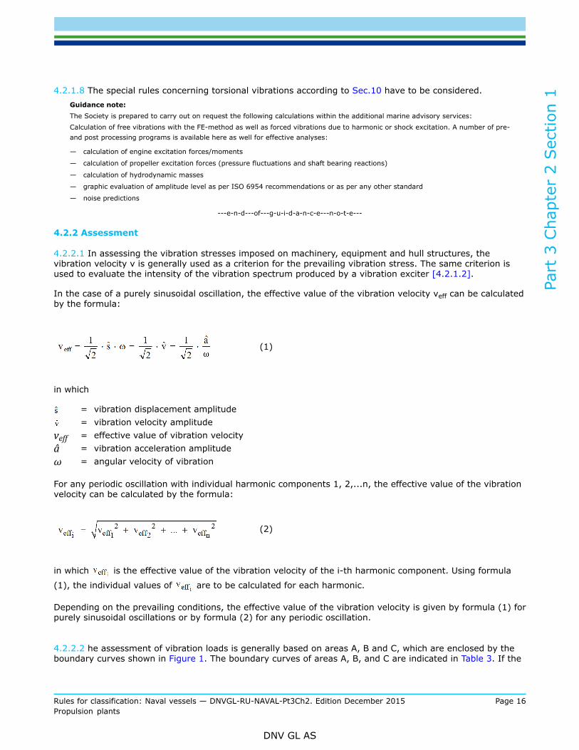
4.2.2.1 In assessing the vibration stresses imposed on machinery, equipment and hull structures, thevibration velocity v is generally used as a criterion for the prevailing vibration stress. The same criterion isused to evaluate the intensity of the vibration spectrum produced by a vibration exciter [4.2.1.2].
In the case of a purely sinusoidal oscillation, the effective value of the vibration velocity veff can be calculatedby the formula:
(1)
in which
= vibration displacement amplitude= vibration velocity amplitude
veff = effective value of vibration velocityâ = vibration acceleration amplitudeω = angular velocity of vibration
For any periodic oscillation with individual harmonic components 1, 2,...n, the effective value of the vibrationvelocity can be calculated by the formula:
(2)
in which is the effective value of the vibration velocity of the i-th harmonic component. Using formula
(1), the individual values of are to be calculated for each harmonic.
Depending on the prevailing conditions, the effective value of the vibration velocity is given by formula (1) forpurely sinusoidal oscillations or by formula (2) for any periodic oscillation.
4.2.2.2 he assessment of vibration loads is generally based on areas A, B and C, which are enclosed by theboundary curves shown in Figure 1. The boundary curves of areas A, B, and C are indicated in Table 3. If the

Part
3 C
hapt
er 2
Sec
tion
1
Rules for classification: Naval vessels — DNVGL-RU-NAVAL-Pt3Ch2. Edition December 2015 Page 17Propulsion plants
DNV GL AS
vibration to be assessed comprises several harmonic components, the effective value according to [4.2.2.1]is to be applied. The assessment of this value shall take account of all important harmonic components in therange from 2 to 300 Hz.
4.2.2.3 Area A can be used for the assessment of all machines, equipment and appliances. Machines,equipment and appliances for use on board a ship shall as a minimum requirement be designed to withstanda vibration load corresponding to the boundary curve of area A.Otherwise, with the Society's consent, steps must be taken (vibration damping, etc.) to reduce the actualvibration load to the permissible level.
4.2.2.4 Because they act as vibration exciters, reciprocating machines are to be separately considered,because they act as vibration exciters. Both the vibration generated by reciprocating machines and thestresses consequently imparted to directly connected peripheral equipment (e.g. governors, exhaust gasturbochargers and lubricating oil pumps) and adjacent machines or apparatus (e.g. generators, transmissionsystems and pipes) can, for the purpose of these rules and with due regard to the limitations stated in[4.2.1.6], be assessed using the substitution quantities presented in [4.2.2.1].
Figure 1 Areas for assessment of vibration loads

Part
3 C
hapt
er 2
Sec
tion
1
Rules for classification: Naval vessels — DNVGL-RU-NAVAL-Pt3Ch2. Edition December 2015 Page 18Propulsion plants
DNV GL AS
Table 3 Numerical definition of the area boundaries shown in Figure 1
Areas A B C A' B'
[mm]
[mm/s]
veff [mm/s]
â [g]
< 1< 20
< 14
< 0.7
< 1< 35
< 25
< 1.6
< 1< 63
< 45
< 4
< 1< 20
< 14
< 1.3
< 1< 40
< 28
< 2.6
4.2.2.4.1 In every case the manufacturer of reciprocating machines has to guarantee permissible vibrationloads for the important directly connected peripheral equipment. The manufacturer of the reciprocatingmachine is responsible to the Society for proving that the vibration loads are within the permissible limits inaccordance with [4.2.3].4.2.2.4.2 Where the vibration loads of reciprocating machines lie within the A' area, separate considerationor verifications relating to the directly connected peripheral equipment [4.2.2.4] are not required. The sameapplies to machines and apparatus located in close proximity to the vibration exciter [4.2.2.4].In these circumstances directly connected peripheral appliances shall in every case be designed for at leastthe limit loads of area B', and machines located nearby for the limit loads of area B.If the permissible vibration loads of individual directly connected peripheral appliances in accordance with[4.2.2.4.1] lie below the boundary curve of area B, permissibility shall be proved by measurement of thevibration load which actually occurs.4.2.2.4.3 If the vibration loads of reciprocating machines lie outside area A' but are still within area B', itshall be proved by measurement that directly connected peripheral appliances are not loaded above thelimits for area C.In these circumstances directly connected peripheral appliances shall in every case be designed for at leastthe limit loads of area C, and machines located nearby for the limit loads of area B.Proof is required that machines and appliances located in close proximity to the main exciter are not subjectto higher loads than those defined by the boundary curve of area B.If the permissible vibration loads of individual, directly connected peripheral appliances or machines inaccordance with[4.2.2.4.1] lie below the stated values, admissibility shall be proved by measurement ofvibration load which actually occurs.4.2.2.4.4 If the vibration loads of reciprocating machines lie outside area B' but are still within area C, itis necessary to ensure that the vibration loads on the directly connected peripheral appliances still remainwithin area C. If this condition cannot be met, the important peripheral appliances are to be in accordancewith [4.2.3] demonstrably designed for the higher loads.Suitable measures (vibration damping, etc.) are to be taken to ensure reliable prevention of excessivevibration loads on adjacent machines and appliances. The permissible loads stated in [4.2.2.4.3] (area B or alower value specified by the manufacturer) continue to apply to these units.4.2.2.4.5 For directly connected peripheral appliances, the Society may approve higher values than thosespecified in [4.2.2.4.2], [4.2.2.4.3] and [4.2.2.4.4], if these are guaranteed by the manufacturer of thereciprocating machine in accordance with [4.2.2.4.1] and are proved in accordance with [4.2.3].Analogously, the same applies to adjacent machines and appliances, if the relevant manufacturer guaranteeshigher values and provides proof of these in accordance with [4.2.3].
4.2.2.5 For appliances, equipment and components which, because of their installation in steering gearcompartments or bow thruster compartments, are exposed to higher vibration stresses, the admissibility ofthe vibration load may, notwithstanding [4.2.2.3], be assessed according to the limits of area B. The designof such equipment shall allow for the above mentioned increased loads.

Part
3 C
hapt
er 2
Sec
tion
1
Rules for classification: Naval vessels — DNVGL-RU-NAVAL-Pt3Ch2. Edition December 2015 Page 19Propulsion plants
DNV GL AS
4.2.3 Proofs
4.2.3.1 Where in accordance with [4.2.2.4.1], [4.2.2.4.4] and [4.2.2.4.5] the Society is asked to approvehigher vibration load values, all that is normally required for this is the binding guarantee of the admissiblevalues by the manufacturer or the supplier.
4.2.3.2 The Society reserves the right to call for detailed proofs (calculations, design documents,measurements etc.) in cases where this is warranted.
4.2.3.3 Type approval in accordance with DNVGL-CG-0339 , are regarded as proof of admissibility of thetested vibration load.
4.2.3.4 The Society may recognize long-term trouble free operation as sufficient proof of the requiredreliability and operational dependability.
4.2.3.5 The manufacturer of the reciprocating machine is in every case responsible to the Society for anyproof which may be required concerning the level of the vibration spectrum generated by the reciprocatingmachine.
4.2.4 Measurement
4.2.4.1 Proof based on measurements is normally required only for reciprocating machines with an outputof more than 100 kW, provided that the other conditions set out in [4.2.2.4.2], [4.2.2.4.4] and [4.2.2.4.4]are met. Where circumstances warrant this, the Society may also require proofs based on measurements forsmaller outputs.
4.2.4.2 Measurements are to be performed in every case under realistic service conditions at the point ofinstallation. During verification, the output supplied by the reciprocating machine shall be not less than 80 %of the rated value. The measurement shall cover the entire available speed range in order to facilitate thedetection of any resonance phenomena.
4.2.4.3 The Society may accept proofs based on measurements which have not been performed at the pointof installation (e.g. test bed runs), but under different mounting conditions, provided that the transferabilityof the results can be proved.The results are normally regarded as transferable in the case of flexibly mounted reciprocating machines ofcustomary design.If the reciprocating machine is not flexibly mounted, the transferability of the results may still beacknowledged if the essential conditions for this (similar bed construction, similar installation and piperouting, etc.) are satisfied.
4.2.4.4 For assessment of the vibration stresses affecting or generated by reciprocating machines normallythe location in which the vibration loads are greatest. Figure 2 indicates the points of measurement which arenormally required for an inline piston engine. The measurement has to be performed in all three directions.In justified cases exceptions can be made to the inclusion of all the measuring points.
4.2.4.5 The measurements can be performed with mechanical manually-operated instruments provided thatthe instrument setting is appropriate to the measured values bearing in mind the measuring accuracy.Directionally selective, linear sensors with a frequency range of at least 2 to 300 Hz should normally beused. Non-linear sensors can also be used provided that the measurements take account of the responsecharacteristic.
4.2.4.6 The records of the measurements for the points at which the maximum loads occur are to besubmitted to the Society together with a tabular evaluation.

Part
3 C
hapt
er 2
Sec
tion
1
Rules for classification: Naval vessels — DNVGL-RU-NAVAL-Pt3Ch2. Edition December 2015 Page 20Propulsion plants
DNV GL AS
Figure 2 Schematic representation of in-line piston engine
4.3 ShockNaval ships may also be exposed to shock forces created by air or underwater explosions from conventionalor nuclear weapons.For naval ships with special ability to withstand shock loads class notation SHOCK may be assigned. Detailsfor shock requirements are described in the Society's rules for Hull Structures and Ship Equipment Ch.1.Sec.16.

Part
3 C
hapt
er 2
Sec
tion
1
Rules for classification: Naval vessels — DNVGL-RU-NAVAL-Pt3Ch2. Edition December 2015 Page 21Propulsion plants
DNV GL AS
5 Materials
5.1 Approved Materials
5.1.1 The materials used for propulsion plants have to fulfil the quality requirements defined in the Society'srules for Metallic Materials and Welding RU SHIP Pt.2. The approved materials for the different systems aredefined in the following Sections.
5.1.2 Materials deviating from the defined quality requirements may only be used with special approval ofthe Society. The suitability of the materials has to be proven.
6 Fuels and consumables for operation
6.1 All fuels and consumables used for the operation of propulsion plants are to be in accordance with therequirements of the manufacturers.The use of heavy fuel oil is not considered in these Naval rules. If required in exceptional cases therequirements of RU SHIP Pt.4 have to be applied.
6.2 The flash point 2 of liquid fuels for the operation of boilers and diesel engines may not be lower than 60°.
6.3 In exceptional cases, for ships intended for operation in limited geographical areas or where specialprecautions subject to the Society approval are taken, fuels with flash points between 43°C and 60°C mayalso be used. This is conditional upon the requirement that the temperatures of the spaces in which fuels arestored or used shall invariably be 10 °C below the flash point.
6.4 The fuel has to be filterable.
6.5 The fresh cooling water for internal combustion engines has to be treated from freshwater and corrosionprotection agent.Fresh water has to comply with the requirements of the engine manufacturer with respect to:
— water hardness, [dGH]— pH value, (at 20°C)— chloride content, [mg/l]
6.6 The storage of fuel and consumables for operation has to follow the requirements of Ch.5 Sec.7.
2 Based, up to 60 °C, on determination of the flash point in a closed crucible (cup test).

Part
3 C
hapt
er 2
Sec
tion
1
Rules for classification: Naval vessels — DNVGL-RU-NAVAL-Pt3Ch2. Edition December 2015 Page 22Propulsion plants
DNV GL AS
7 Safety equipment and protective measuresMachinery is to be installed and safeguarded in such a way that the risk of accidents is largely ruled out.Besides of national regulations particular attention is to be paid to the following:It has to be ensured that physical arrangements for machinery and equipment do not pose a risk topersonnel.
7.1 Moving parts, flywheels, chain and belt drives, linkages and other components which could constitute anaccident hazard for the operating personnel are to be fitted with guards to prevent contact. The same appliesto hot machine parts, pipes and walls for which no thermal insulation is provided, e.g. pressure lines to aircompressors.
7.2 The design and installation of all systems and equipment has to ensure that elements, which have to be usedduring normal operation of the ship by the crew and where no thermal insulation is provided, are kept withinthe following restrictions concerning accidental contact of hot surfaces.
7.2.1 No skin contact is possible with elements warmed up under operating conditions to surfacetemperature above 70°C.
7.2.2 Components, which may be used without body protection, e.g. protective gloves and with a contacttime up to 5 s, are to have no higher surface temperature than 60 °C.
7.2.3 Components made of materials with high thermal conductivity, which may be used without bodyprotection and a contact time of more than 5 s are not to achieve a surface temperature above 45°C.
7.2.4 Exhaust gas lines and other apparatus and lines transporting hot media have to be insulatedeffectively. Insulation material has to be non-combustible. Locations where inflammable liquids or moisturemay penetrate into the insulation are to be protected in a suitable way by coverings, etc.
7.3 When using hand cranks for starting internal combustion engines, steps are to be taken to ensure that thecrank disengages automatically when the engine starts.Dead-Man's circuits are to be provided for rotating equipment.
7.4 Blowdown and drainage facilities are to be designed in such a way that the discharged medium can be safelydrained off.
7.5 In operating spaces, anti-skid floor plates and floor coverings are to be used.
7.6 Service gangways, operating platforms, stairways and other areas open to access during operation are tobe safeguarded by guard rails. The outside edges of platforms and floor areas are to be fitted with coamingsunless some other means is adopted to prevent persons and objects from sliding off.

Part
3 C
hapt
er 2
Sec
tion
1
Rules for classification: Naval vessels — DNVGL-RU-NAVAL-Pt3Ch2. Edition December 2015 Page 23Propulsion plants
DNV GL AS
7.7 Glass water level gauges for auxiliary steam boilers are to be equipped with protection devices.Devices for blowing through water level gauges shall be capable of safe operation and observation.
7.8 Safety valves and shutoffs are to be capable of safe operation. Fixed steps, stairs or platforms are to be fittedwhere necessary.
7.9 Safety valves are to be installed to prevent the occurrence of excessive operating pressures.
7.10 Steam and feedwater lines, exhaust gas ducts, auxiliary boilers and other equipment and pipelines carryingsteam or hot water are to be effectively insulated. Insulating materials are to be incombustible. Points atwhich combustible liquids or moisture can penetrate into the insulation are to be suitably protected, e.g. bymeans of shielding.
7.11 For machinery which is operated in hazardous areas, provisions are to be established to avoid the risk ofignition. These might be design measures, monitoring of criterial parameters and/or bring the machinery in asafe condition.
8 Survivability
8.1 DefinitionSurvivability of a naval ship is to be regarded as the degree of ability to withstand a defined weapon threatand to maintain at least a basic degree of safety and operability of the ship.It is obvious that survivability is an important characteristic of a naval ship which may be endangered by:
— loss of global strength of the hull structure— loss of buoyancy and/or stability— loss of manoeuvrability— fire in the ship and ineffective fire protection or fire fighting capability— direct destruction of machinery, equipment or control systems— direct destruction of weapons and sensors— threat to the crew
8.2 Measures for improved survivabilityThe design of a ship which is classed as naval ship has to consider a series of possible measures to improvesurvivability. These Part 3 rules for naval surface ships offer in the different Chapters various measures andclass notations to achieve improved survivability. The degree of including such measures in an actual projecthas to be defined by the naval administration.

Part
3 C
hapt
er 2
Sec
tion
1
Rules for classification: Naval vessels — DNVGL-RU-NAVAL-Pt3Ch2. Edition December 2015 Page 24Propulsion plants
DNV GL AS
8.3 Measures for the propulsion plantIn this Chapter the following main measure to improve survivability is included.
8.3.1 Redundant propulsionThe requirements for the class notations RP(1, x) to RP(3, x) concerning redundant propulsion andmanoeuvrability are defined in Sec.2 [11].

Part
3 C
hapt
er 2
Sec
tion
2
Rules for classification: Naval vessels — DNVGL-RU-NAVAL-Pt3Ch2. Edition December 2015 Page 25Propulsion plants
DNV GL AS
SECTION 2 DESIGN AND CONSTRUCTION OF THE MACHINERYINSTALLATION
1 General
1.1 As far as necessary for function and safe operation, the design of the propulsion plant has to consider thesize and experience of the crew according to the mission statement of the actual naval ship.
1.2 Normally it can be assumed, that:
— no personnel is permanently present in machinery rooms— in machinery rooms inspection patrols will be made in regular time intervals— the machinery control centre (MCC) is permanently manned
1.3 The operating and maintenance instructions, warning signs, etc. have to be prepared in English and in theuser's language.
2 Dimensions of components
2.1 General
2.1.1 All parts are to be capable of withstanding the stresses and loads peculiar to shipboard service, e.g.those due to movements of the ship, vibrations, intensified corrosive attack, temperature changes and waveimpact, and shall be dimensioned in accordance with the requirements set out in the present Chapter.The ambient conditions acc. to Sec.1 [4] and Sec.1 [5] , have to be considered.In the absence of rules governing the dimensions of parts, the recognized rules of engineering practice are tobe applied.
2.1.2 Where connections exist between systems or plant items which are designed for different forces,pressures and temperatures (stresses), safety devices are to be fitted which prevent the over-stressing ofthe system or plant item designed for the lower design parameters. To preclude damage, such systems areto be fitted with devices affording protection against excessive pressures and temperatures and/or againstoverflow.
2.2 MaterialsAll components subject to these rules shall comply with RU SHIP Pt.2.
2.3 WeldingThe fabrication of welded components, the approval of companies and the testing of welders are subject tothe requirements of RU SHIP Pt.2 Ch.4.

Part
3 C
hapt
er 2
Sec
tion
2
Rules for classification: Naval vessels — DNVGL-RU-NAVAL-Pt3Ch2. Edition December 2015 Page 26Propulsion plants
DNV GL AS
2.4 Screw connections
2.4.1 Screws are to be designed according to proven and acknowledged principles.
2.4.2 he design of screw connections between equipment and foundations has to avoid shear forces orbending moments in the screws, only tensional forces in axial direction are allowed. Therefore, the flangeswhere the screw forces are acting have to be stiffened with a suitable number of brackets to avoid flangebending, which would create bending moments to the screws.
2.4.3 Only closed holes in flanges shall be provided for screws, because under shock influence screwsmight slip out of a hole in form of a half open slot. In addition friction connections are not safe under shockinfluence.
Guidance note:If expansion screws are used, the peak stresses at the core of the thread are reduced, because the maximum stress will occur atthe location of the reduced shaft section. If such screws are long enough, they will be able to protect the mounted equipment fromshock loads to some extent, because the elongation of the shaft reduces acceleration peaks.It is also recommendable to use cap nuts together with expansion screws for connections. With this form of nut the load on thedifferent turns of the thread is nearly the same, which helps to avoid excessive local stresses.If a normal screw is fitted into a threaded hole, the breaking of the screw because of the severe transverse dynamic shock loads willbe evident at the first turn of the thread coming out of the hole. This is the case because of the adding up of the bending stress to themaximum axial stress which occurs at this turn. The problem can be solved by a flat necking of the shaft above the last turn of thethread or by a special form of shaft and hole. The bolt is in the latter case provided with a small collar fitting in the upper part of thehole. Thus the biggest part of the bending stress will be transmitted at the collar and is separated from the axial stress at the thread.
---e-n-d---of---g-u-i-d-a-n-c-e---n-o-t-e---
2.5 Tests
2.5.1 Machinery and its component parts are subject to constructional and material tests, pressure andleakage tests, and trials. All the tests prescribed in the following Sections are to be conducted undersupervision of the Society.In case of parts produced in series, other methods of testing may be agreed with the Society instead of thetests prescribed, provided that the former are recognized as equivalent by the Society.
2.5.2 The Society reserves the right, where necessary, to increase the scope of tests and also to subject totesting those parts which are not expressly required to be tested according to the rules.
2.5.3 Components subject to mandatory testing are to be replaced by tested parts.
2.5.4 After installation on board of the main and auxiliary machinery, operational functioning of themachinery including associated ancillary equipment is to be verified. All safety equipment is to be tested,unless adequate testing has already been performed at the manufacturer's works in the presence of asurveyor.In addition, the entire machinery installation is to be tested during sea trials, as far as possible under theintended service conditions.
2.6 Corrosion protectionParts which are exposed to corrosion are to be safeguarded by being manufactured of corrosion-resistantmaterials or provided with effective corrosion protection.

Part
3 C
hapt
er 2
Sec
tion
2
Rules for classification: Naval vessels — DNVGL-RU-NAVAL-Pt3Ch2. Edition December 2015 Page 27Propulsion plants
DNV GL AS
3 Availability of machinery
3.1 Ship's machinery is to be so arranged and equipped that it can be brought into operation from the "deadship" condition with the means available on board.The "dead ship" condition means that the entire machinery installation including the electrical power supplyis out of operation and auxiliary sources of energy such as starting air, battery-supplied starting current etc.are not available for restoring the ship's electrical system, restarting auxiliary operation and bringing thepropulsion installation back into operation.To overcome the "dead ship" condition use may be made of an emergency generator set provided that it isensured that the electrical power for emergency services is available at all times.
3.2 In case of "dead ship" condition it is to be ensured that it will be possible for the propulsion system and allnecessary auxiliary machinery to be restarted within a period of 30 minutes, see the Society's rules for ShipOperation Installations and Auxiliary Systems Ch.5 Sec.6 [1.4]
4 Control and regulating
4.1 Machinery is to be so equipped that it can be controlled in accordance with operating requirements in such away that the service conditions prescribed by the manufacturer can be met.
4.1.1 For the control equipment of main engines and systems essential for operation see, Ch.3, AutomationCh.4 and Ch.5.
4.2 In the event of failure or fluctuations of the supply of electrical, pneumatic or hydraulic power to regulatingand control systems, or in case of a break in a regulating or control circuit, steps are to be taken to ensurethat:
— the appliances remain at their present operational setting or, if necessary, are changed to a setting whichwill have the minimum adverse effect on operation (fail-safe conditions)
— the power output or engine speed of the machinery being controlled or governed is not increased— no unintentional start-up sequences are initiated
4.3 Each driving machinery has to be provided with an emergency stopping device.
4.4 Manual operationEvery essential automatically or remote controlled system shall also be capable of manual operation, seeCh.4.A manual emergency stopping device has to be provided.
Part
3 C
hapt
er 2
Sec
tion
2
Rules for classification: Naval vessels — DNVGL-RU-NAVAL-Pt3Ch2. Edition December 2015 Page 28Propulsion plants
DNV GL AS
5 Propulsion plant
5.1 General
5.1.1 All devices forming a part of the propulsion plant have to be provided with peripheral componentswhich ensure a faultless handling as well as a simple and safe operation and control, even if they are notspecified in detail.
5.1.2 All auxiliary machinery and the control units directly needed for the operation of the propulsion plantare to be located as near as possible to the driving machinery.
5.1.3 Manoeuvring equipmentEvery engine control stand is to be equipped in such a way that:
— the propulsion plant can be adjusted to any setting— the direction of propulsion can be reversed— the propulsion unit or the propeller shaft can be stopped
5.1.4 If required in the building specification, the driving machinery has to be designed and equipped foroperation in a sound protection capsule.Using sound protection capsules the relative movement between the driving machinery and the shipsidepiping system has to be compensated by flexible connections. If applicable, the elastic mounting of thedriving machinery has to be taken into account.
5.1.5 For connected pumps no electrically driven stand by pumps are to be provided if the propulsion isensured by several driving machines.
5.1.6 The remote control of the propulsion plant from the bridge is subject to Ch.4.
5.2 Multiple-shaft and multi-engine systems5.2.1 Definitions
5.2.1.1 CODADCODAD is the abbreviation for COmbined Diesel engine And Diesel engine. In this configuration a propulsionshaft can be driven alternatively by one diesel engine or several diesel engines, see Figure 1.
5.2.1.2 CODAGCODAG is the abbreviation for COmbined Diesel engine And Gas turbine. In this configuration a propulsionshaft can be driven alternatively by a diesel engine or by a gas turbine or by both, see Figure 2.
5.2.1.3 CODOGCODOG is the abbreviation for COmbined Diesel engine Or Gas turbine. In this configuration a propulsionshaft can be driven alternatively by a diesel engine or a gas turbine, see Figure 3.
5.2.1.4 COGAGCOGAG is the abbreviation for COmbined Gas turbine And Gas turbine. In this configuration a propulsionshaft can be driven alternatively by one gas turbine or by several gas turbines, see Figure 4.
5.2.1.5 COGOGCOGOG is the abbreviation for COmbined Gas turbine Or Gas turbine. In this configuration a propulsion shaftcan be driven alternatively by one or the other gas turbine, see Figure 5.

Part
3 C
hapt
er 2
Sec
tion
2
Rules for classification: Naval vessels — DNVGL-RU-NAVAL-Pt3Ch2. Edition December 2015 Page 29Propulsion plants
DNV GL AS
5.2.1.6 CODELAGCODELAG is the abbreviation for COmbined Diesel ELectric And Gasturbine. In this configuration a propellershaft can be driven alternatively by one or two electric motors, only by the gas turbine or by electric motorand gas turbine together. The electric drive will be chosen if the radiated noise has to be minimized and forcruising speed νM. The combination of electric motors and gas turbine has to be applied for maximum speedvmax, see Figure 6.
5.2.1.7 IEPIEP is the abbreviation for Integrated Electric Propulsion. In this configuration the electric power is generatedby several diesel gen sets and/or gas turbine gen sets. According to the actual speed requirements therequired power for propulsion will be delivered to the electric propulsion motor of each propeller shaft, seeFigure 7.
5.2.1.8 AZPAZP is the abbreviation for AZimuthing Propulsion. In this configuration the electric power is generated byseveral diesel gen sets and/or gas turbine gen sets. The drive of the propulsors is done directly by electricmotors in the azimuthing pods (without transmitting shaft), see Figure 8.
5.2.2 If a ship is equipped with several propulsion machines, it shall be possible to disengage the differentpropulsion engines from the power transmitting unit. At manual or automatic emergency stops of an engine,the relevant clutch has to disconnect automatically.
5.2.3 Steps are to be taken to ensure that in the event of a failure of a propulsion engine, operation can bemaintained with remaining engines, where appropriate by a simple change-over system.
5.2.4 Multiple shaft systemsA space separation between driving engines and driving gear shall be provided, if possible.All necessary provisions have to be made, that:
— only one propulsion shaft can be used and no overloading occurs— starting and operation is possible with every driving engine intended to drive a propulsion shaft,
independently from the other propulsion shafts
For the additional class notation redundant propulsion RP see RU SHIP Pt.6 Ch.2 Sec.2.For multiple-shaft systems, each shaft is to be provided with a locking device which prevents dragging of theshaft.
Figure 1 Principle arrangement for CODAD propulsion plant

Part
3 C
hapt
er 2
Sec
tion
2
Rules for classification: Naval vessels — DNVGL-RU-NAVAL-Pt3Ch2. Edition December 2015 Page 30Propulsion plants
DNV GL AS
Figure 2 Principle arrangement for CODAG propulsion plant
Figure 3 Principle arrangement for CODOG propulsion plant
Figure 4 Principle arrangement for COGAG propulsion plant

Part
3 C
hapt
er 2
Sec
tion
2
Rules for classification: Naval vessels — DNVGL-RU-NAVAL-Pt3Ch2. Edition December 2015 Page 31Propulsion plants
DNV GL AS
Figure 5 Principle arrangement for COGOG propulsion plant
Figure 6 Principle arrangement for CODELAG plant
Figure 7 Principle arrangement for Integrated Electric Propulsion (IEP)

Part
3 C
hapt
er 2
Sec
tion
2
Rules for classification: Naval vessels — DNVGL-RU-NAVAL-Pt3Ch2. Edition December 2015 Page 32Propulsion plants
DNV GL AS
Figure 8 Principle arrangement for Azimuthing Propulsion (AZP)
Explanation of symbols used in Figures 1 to 8
6 Turning appliances
6.1 Machinery is to be equipped with suitable and adequately dimensioned turning appliances.
6.2 The turning appliances are to be of self-locking type. Electric motors are to be fitted with suitable retainingbrakes.
6.3 An automatic interlocking device is to be provided to ensure that the propulsion and auxiliary prime moverscannot start up while the turning gear is engaged. In case of manual turning installations warning devicesmay be provided alternatively.
7 Operating and maintenance instructionsManufacturers of machinery, boilers and auxiliary equipment shall supply a sufficient number of operatingand maintenance notices and manuals together with the equipment.In addition, an easily legible board is to be mounted on boiler operating platforms giving the most importantoperating instructions for boilers and oil-firing equipment.
8 Markings, identificationIn order to avoid unnecessary operating and switching errors, all parts of the machinery whose function isnot immediately apparent are to be adequately marked and labelled.

Part
3 C
hapt
er 2
Sec
tion
2
Rules for classification: Naval vessels — DNVGL-RU-NAVAL-Pt3Ch2. Edition December 2015 Page 33Propulsion plants
DNV GL AS
9 Engine room equipment
9.1 Operating and monitoring equipment
9.1.1 Instruments, warning and indicating systems and operating appliances are to be clearly displayed andconveniently sited. Absence of dazzle, particularly on the bridge, is to be ensured.Operating and monitoring equipment is to be grouped in such a way as to facilitate easy supervision andcontrol of all important parts of the installation.The following requirements are to be observed when installing systems and equipment:
— protection against humidity and the effects of dirt— avoidance of excessive temperature variations— adequate ventilation
In consoles and cabinets containing electrical or hydraulic equipment or lines carrying steam or water theelectrical gear is to be protected from damage due to leakage.Redundant ventilation systems are to be provided for air-conditioned machinery and control rooms.
9.1.2 Pressure gaugesThe scales of pressure gauges are to be dimensioned up to the specified test pressure. The maximumpermitted operating pressures are to be marked on the pressure gauges for boilers, pressure vessels and insystems protected by safety valvesPressure gauges are to be installed in such a way that they can be isolated.Lines leading to pressure gauges are to be installed in such a way that the readings cannot be affected byliquid heads and hydraulic hammer.
9.2 Accessibility of machinery and boilers
9.2.1 Machinery and boiler installations, apparatuses, control and operating devices are to be easilyaccessible and visible for operation and maintenance. National regulations have to be observed.
9.2.2 In the layout of machinery spaces (design of foundation structures, laying of pipelines and cableconduits, etc.) and for the design of machinery and equipment (mountings for filters, coolers, etc.) [9.2.1] isto be complied with.For the installation and the dismantling of the propulsion machinery, openings of sufficient size have to beprovided; for all other parts of the equipment installation and dismantling routes have to be planned.Fixtures for transport devices have to be provided.The installation of components within the installation routes has to be avoided or the components are to bedismountable.
9.3 Machinery control centreMachinery control centres (MCC) are to be provided with at least two exits, one of which can also be used asan escape route.
9.4 LightingAll operating spaces are to be adequately lit to ensure that control and monitoring instruments can be easilyread. In this connection see the rules defined in the Society's rules for Electrical Installation Ch.3 Sec.11.

Part
3 C
hapt
er 2
Sec
tion
2
Rules for classification: Naval vessels — DNVGL-RU-NAVAL-Pt3Ch2. Edition December 2015 Page 34Propulsion plants
DNV GL AS
9.5 Bilge wells/ bilgesSee rules defined in Ch.5 Sec.8.
9.6 VentilationThe design and construction of ventilation systems are subject to the requirements defined in Ch.5 Sec.11.
9.7 Noise abatementIn compliance with the relevant national regulations, care is to be taken to ensure that operation of the shipis not unacceptably impaired by engine noise, e.g. by means of shielding.
10 Communication and signalling equipment
10.1 Voice communicationMeans of voice communication are to be provided between the ship's manoeuvring station, the engine roomand the steering gear compartment, and these means shall allow fully satisfactory intercommunicationindependent from the shipboard power supply under all operating conditions (see Ch.3 Sec.9).
10.2 Duty alarm systemFrom the engine room or the machinery control centre a duty alarm system for the engineer officers has tobe established for the off-duty period. See Ch.3 Sec.9 [3.5].
10.3 Engine telegraphMachinery operated from the engine room is to be equipped with a telegraph.In the case of multiple-shaft installations, a telegraph is to be provided for each unit.Local control stations are to be equipped with an emergency telegraph.
10.4 Shaft revolution indicatorThe speed and direction of rotation of the propeller shafts are to be indicated on the bridge, in the engineroom respectively in all control stations. In the case of small propulsion units, the indicator may be dispensedwith.Barred speed ranges are to be marked on the shaft revolution indicators.
10.5 Design of communication and signalling equipmentReversing, command transmission and operating controls, etc. are to be grouped together at a convenientpoint at the control stations.The current status, "Ahead" or "Astern", of the reversing control is to be clearly indicated on the propulsionplant at the control stations.Signalling devices are to be clearly perceptible from all parts of the engine room when the machinery is in fulloperation.For details of the design of electrically operated command transmission, signalling and alarm systems, seeCh.3 and Ch.4.

Part
3 C
hapt
er 2
Sec
tion
2
Rules for classification: Naval vessels — DNVGL-RU-NAVAL-Pt3Ch2. Edition December 2015 Page 35Propulsion plants
DNV GL AS
11 Redundant systems
11.1 General
11.1.1 Ships complying with the rules for redundant propulsion and steering as described in RU SHIP Pt.6Ch.2 Sec.7 may be assigned one of the following notations RP(1,x), RP(2,x) or RP(3,x).In the following an overview for general information about these rules shall be given.
11.1.2 The rules for redundant propulsion and steering systems stipulate the level of redundancy for thepropulsion and steering systems. It is characterised by the appropriate notation to be affixed to the Characterof Classification as defined in the Pt.1 Ch.3.

Part
3 C
hapt
er 2
Sec
tion
3
Rules for classification: Naval vessels — DNVGL-RU-NAVAL-Pt3Ch2. Edition December 2015 Page 36Propulsion plants
DNV GL AS
SECTION 3 INTERNAL COMBUSTION ENGINES
1 General
1.1 ScopeThe rules contained in this Section are valid for internal combustion engines as main and auxiliary drives.Internal combustion engines in the sense of these rules are four-stroke diesel engines with trunk piston.
1.2 Ambient conditionsFor all engines, which are used on ships with unrestricted range of service, the definition of the performancehas to be based on the ambient conditions according to Sec.1 [4].The defined seawater temperature has especially to be considered as inlet temperature to coolers for chargeair coolant operating with seawater.
1.3 Rated power
1.3.1 Diesel engines are to be designed such that their rated power when running at rated speed accordingto the definitions of the engine manufacturer at ambient conditions as defined in Sec.1 [4] can be deliveredas continuous power. Diesel engines are to be capable of continuous operation within power range 1 inFigure 1 and intermittently in power range 2. The extent of the power ranges are to be stated by the enginemanufacturer.
1.3.2 Continuous power is to be understood as the standard service power which an engine is capable ofdelivering continuously, provided that the maintenance prescribed by the engine manufacturer is carried out,between the maintenance intervals stated by the engine manufacturer.
1.3.3 To verify that an engine is rated at its continuous power, it is to be demonstrated that the enginecan run at an overload power corresponding to 110% of its rated power at corresponding speed for anuninterrupted period of 1 hour. Deviations from the overload power value require the agreement of theSociety.
1.3.4 Engines, which have to meet the requirements of a permanent low-load operation according tothe mission statement of the naval ship, have to be designed with regard to bad combustion and lowtemperatures. Relevant measures and additional equipment have to be approved by the Society.
1.3.5 After running on the test bed, the fuel delivery system of main engines is to be so adjusted that afterinstallation on board overload power cannot be given delivered. The limitation of the fuel delivery system hasto be secured permanently.
1.3.6 Subject to the prescribed conditions, diesel engines driving electric generators are to be capable ofoverload operation even after installation on board.
1.3.7 Subject to the approval by the Society, diesel engines may be designed for a continuous power (fuelstop power) which cannot be exceeded.
1.3.8 For main engines, a power diagram (Figure 1) is to be prepared showing the power ranges withinwhich the engine is able to operate continuously and for short periods under service conditions.
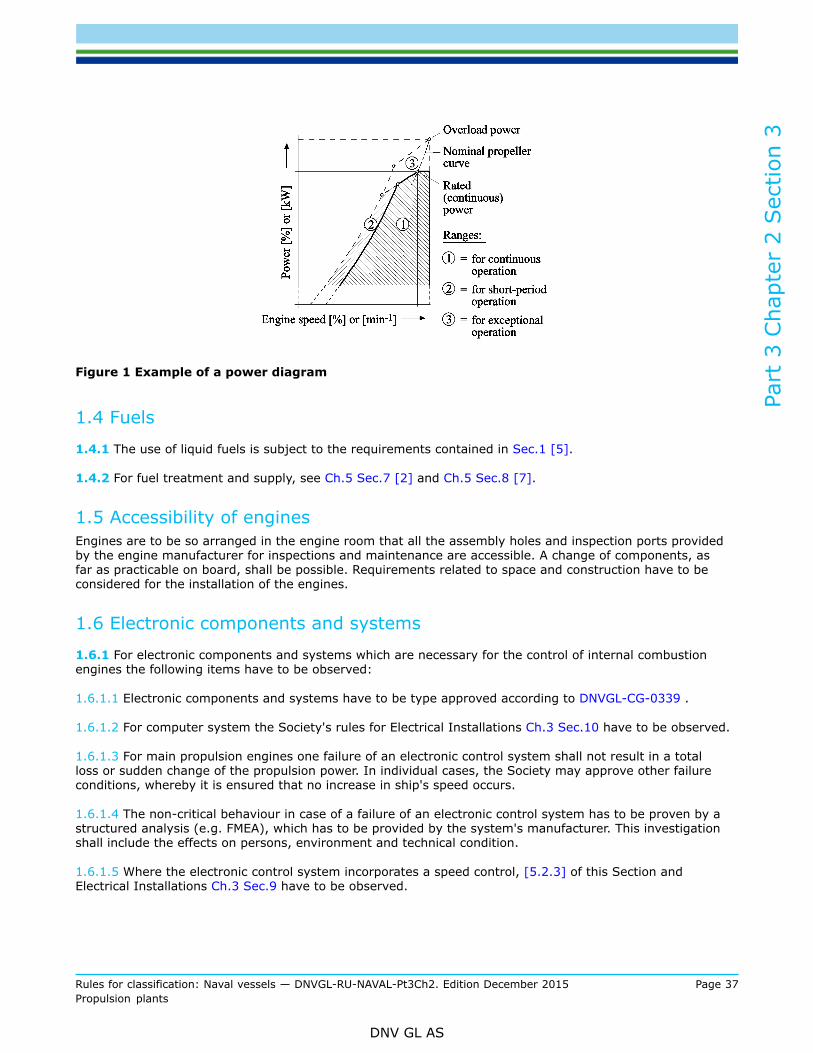
Part
3 C
hapt
er 2
Sec
tion
3
Rules for classification: Naval vessels — DNVGL-RU-NAVAL-Pt3Ch2. Edition December 2015 Page 37Propulsion plants
DNV GL AS
Figure 1 Example of a power diagram
1.4 Fuels
1.4.1 The use of liquid fuels is subject to the requirements contained in Sec.1 [5].
1.4.2 For fuel treatment and supply, see Ch.5 Sec.7 [2] and Ch.5 Sec.8 [7].
1.5 Accessibility of enginesEngines are to be so arranged in the engine room that all the assembly holes and inspection ports providedby the engine manufacturer for inspections and maintenance are accessible. A change of components, asfar as practicable on board, shall be possible. Requirements related to space and construction have to beconsidered for the installation of the engines.
1.6 Electronic components and systems
1.6.1 For electronic components and systems which are necessary for the control of internal combustionengines the following items have to be observed:
1.6.1.1 Electronic components and systems have to be type approved according to DNVGL-CG-0339 .
1.6.1.2 For computer system the Society's rules for Electrical Installations Ch.3 Sec.10 have to be observed.
1.6.1.3 For main propulsion engines one failure of an electronic control system shall not result in a totalloss or sudden change of the propulsion power. In individual cases, the Society may approve other failureconditions, whereby it is ensured that no increase in ship's speed occurs.
1.6.1.4 The non-critical behaviour in case of a failure of an electronic control system has to be proven by astructured analysis (e.g. FMEA), which has to be provided by the system's manufacturer. This investigationshall include the effects on persons, environment and technical condition.
1.6.1.5 Where the electronic control system incorporates a speed control, [5.2.3] of this Section andElectrical Installations Ch.3 Sec.9 have to be observed.

Part
3 C
hapt
er 2
Sec
tion
3
Rules for classification: Naval vessels — DNVGL-RU-NAVAL-Pt3Ch2. Edition December 2015 Page 38Propulsion plants
DNV GL AS
1.6.2 Local control station
1.6.2.1 For the local control station, 8 has to be observed.
1.6.2.2 The indicators named in 8 shall be realised in such a way that one failure can only affect a singleindicator. Where these indicators are an integral part of an electronic control system, means shall be taken tomaintain these indications in case of failure of such a system.
1.6.2.3 Where these indicators are realised electrically, the power supply of the instruments and of theelectronic system has to be realised in such way to ensure the behaviour stated in [1.6.2.2].
2 Documents for approval
2.1 For each engine type the drawings and documents listed in Table 1 shall, wherever applicable, be submittedby the engine manufacturer to the Society for approval (A) or information (R).Where considered necessary, the Society may request further documents to be submitted. This also appliesto the documentation of design changes according to [2.4].
2.2 Engines manufactured under licenseFor each engine type manufactured under licence, the licensee shall submit to The Society, as a minimumrequirement, the following documents:
— comparison of all the drawings and documents as per Table 1 - where applicable - indicating the relevantdrawings used by the licensee and the licensor
— all drawings of modified components, if available, as per Table 1 together with the licensor's declaration ofconsent to the modifications
— a complete set of drawings at the disposal of the local inspection office of the Society as a basis for theperformance of tests and inspections
2.3 Definition of a diesel engine typeThe type specification of an internal combustion engine is defined by the following data:
— manufacturer's type designation— cylinder bore— stroke— method of injection— fuels which can be used— working cycle (4-stroke)— method of gas exchange (naturally aspirated or supercharged)— rated power per cylinder at rated speed as well as mean effective pressure, mean indicated pressure and
maximum firing pressure— method of pressure charging (pulsating pressure system or constant-pressure system)— charge air cooling system— cylinder arrangement (in-line, vee)
2.4 Design modificationsFollowing initial approval of an engine type by the Society, only those documents listed in Table 1 require tobe resubmitted for examination which embody important design modifications.

Part
3 C
hapt
er 2
Sec
tion
3
Rules for classification: Naval vessels — DNVGL-RU-NAVAL-Pt3Ch2. Edition December 2015 Page 39Propulsion plants
DNV GL AS
2.5 Approval of engine componentsThe approval of exhaust gas turbochargers, heat exchangers, engine-driven pumps, etc. is to be requestedfrom the Society by the respective manufacturer.
Table 1 Documents for approval
SerialNo. A/R Description Quantity Remarks(seebelow)
1 R Details required on forms F 144 and F 144/1 when applying forapproval of an internal combustion engine 3
2 R Engine transverse cross-section 3
3 R Engine longitudinal section 3
Bedplate or crankcase
R – cast 14
A – welded, with welding details and instructions 3 9
5 A Thrust bearing assembly 3 3
Thrust bearing base plate:
R – cast 16
A – welded, with welding details and instructions 3 9
Frame/framebox
R – cast 1 17
A – welded, with welding details and instructions 3 1, 9
8 R Tie rod 1
9 R Cylinder cover/head, assembly 1
10 R Cylinder liner 1
11 A Crankshaft for each number of cylinders, with data sheets forcalculation of crankshafts 3
12 A Crankshaft assembly, for each number of cylinders 3
13 A Thrust shaft or intermediate shaft (if integral with engine) 3
14 A Shaft coupling bolts 3
15 A Counterweights including fastening bolts 3
16 R Connecting rod, details 3
17 R Connecting rod, assembly 3
18 R Piston assembly 1
19 R Camshaft drive, assembly 1
20 A Material specifications of main parts with information on non-destructive material tests and pressure tests 3 8
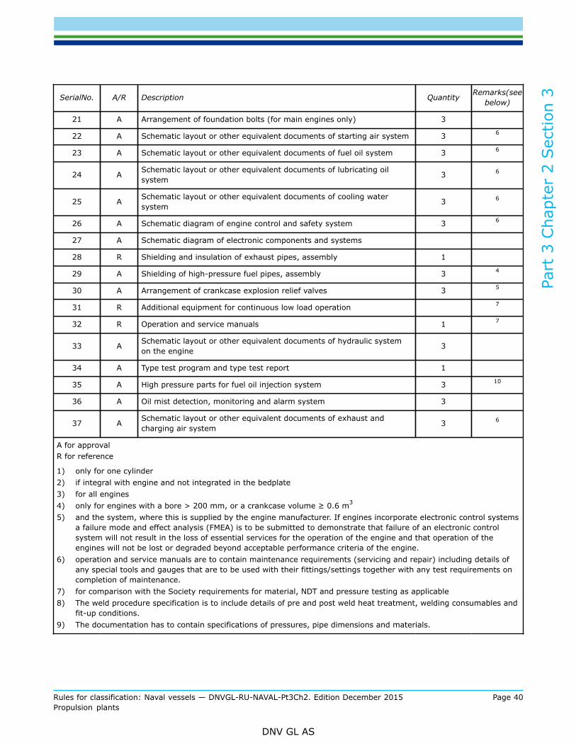
Part
3 C
hapt
er 2
Sec
tion
3
Rules for classification: Naval vessels — DNVGL-RU-NAVAL-Pt3Ch2. Edition December 2015 Page 40Propulsion plants
DNV GL AS
SerialNo. A/R Description Quantity Remarks(seebelow)
21 A Arrangement of foundation bolts (for main engines only) 3
22 A Schematic layout or other equivalent documents of starting air system 3 6
23 A Schematic layout or other equivalent documents of fuel oil system 3 6
24 A Schematic layout or other equivalent documents of lubricating oilsystem 3 6
25 A Schematic layout or other equivalent documents of cooling watersystem 3 6
26 A Schematic diagram of engine control and safety system 3 6
27 A Schematic diagram of electronic components and systems
28 R Shielding and insulation of exhaust pipes, assembly 1
29 A Shielding of high-pressure fuel pipes, assembly 3 4
30 A Arrangement of crankcase explosion relief valves 3 5
31 R Additional equipment for continuous low load operation 7
32 R Operation and service manuals 1 7
33 A Schematic layout or other equivalent documents of hydraulic systemon the engine 3
34 A Type test program and type test report 1
35 A High pressure parts for fuel oil injection system 3 10
36 A Oil mist detection, monitoring and alarm system 3
37 A Schematic layout or other equivalent documents of exhaust andcharging air system 3 6
A for approvalR for reference
1) only for one cylinder2) if integral with engine and not integrated in the bedplate3) for all engines4) only for engines with a bore > 200 mm, or a crankcase volume ≥ 0.6 m3
5) and the system, where this is supplied by the engine manufacturer. If engines incorporate electronic control systemsa failure mode and effect analysis (FMEA) is to be submitted to demonstrate that failure of an electronic controlsystem will not result in the loss of essential services for the operation of the engine and that operation of theengines will not be lost or degraded beyond acceptable performance criteria of the engine.
6) operation and service manuals are to contain maintenance requirements (servicing and repair) including details ofany special tools and gauges that are to be used with their fittings/settings together with any test requirements oncompletion of maintenance.
7) for comparison with the Society requirements for material, NDT and pressure testing as applicable8) The weld procedure specification is to include details of pre and post weld heat treatment, welding consumables and
fit-up conditions.9) The documentation has to contain specifications of pressures, pipe dimensions and materials.

Part
3 C
hapt
er 2
Sec
tion
3
Rules for classification: Naval vessels — DNVGL-RU-NAVAL-Pt3Ch2. Edition December 2015 Page 41Propulsion plants
DNV GL AS
3 Crankshaft calculation
3.1 Design methods
3.1.1 Crankshafts shall be designed to withstand the stresses occurring when the engine runs at ratedpower. Calculations are to be based on DNVGL-CG-0037 Calculation of crankshafts for reciprocatinginternal combustion engines . Other methods of calculation may be used provided that they do not resultin crankshaft dimensions smaller than those obtained by applying the aforementioned regulations. Thedocumentation has to be submitted for approval.
3.1.2 Outside the end bearings, crankshafts designed according to the requirements specified in [3.1.1] maybe adapted to the diameter of the adjoining shaft by a generous fillet (r ≥ 0.06 · d) or a taper.
3.1.3 Design methods for application to crank-shafts of special construction and to the crankshafts ofengines of special type are to be agreed with the Society.
3.2 Shrink joints of built-up crankshaftsThe shrink joints of built-up crankshafts are to be designed in accordance with the Society's Guidelines asdefined in [3.1.1].
3.3 Screw joints3.3.1 Split crankshaftsOnly fitted bolts may be used for assembling split crankshafts.
3.3.2 Power-end flange couplingsThe bolts used to connect power-end flange couplings are normally to be designed as fitted bolts inaccordance with Sec.6 [4.4].If the use of fitted bolts is not feasible, the Society may agree to the use of an equivalent frictional resistancetransmission. In these cases the corresponding calculations are to be submitted for approval.
3.4 Torsional vibrationsTorsional vibrations, critical speeds [10] applies.
4 Materials
4.1 Approved materials
4.1.1 The mechanical characteristics of materials used for the components of Diesel engines shall conform toRU SHIP Pt.2. The materials approved for the various components are shown in Table 3.3 together with theirminimum required characteristics and material Certificates.
4.1.2 Materials with properties deviating from those specified may be used only with the Society's specialapproval. The Society requires proof of the suitability of such materials.
4.1.3 If shock loads gain great importance for the naval ship, cast iron with lamellar graphit (GG) is notrecommendable for components exposed to such loads. It may only be used if it is proven that the shockloads are sufficiently reduced by adequate mountings.

Part
3 C
hapt
er 2
Sec
tion
3
Rules for classification: Naval vessels — DNVGL-RU-NAVAL-Pt3Ch2. Edition December 2015 Page 42Propulsion plants
DNV GL AS
4.2 Testing of materials
4.2.1 In the case of individually produced engines, the following parts are to be subjected to material tests inthe presence of the surveyor.
1) Crankshaft2) Crankshaft coupling flange for main power transmission (if not forged to crankshaft)3) Crankshaft coupling bolts4) Pistons or piston crowns made of steel, cast steel or nodular cast iron5) Connecting rod6) Cylinder liners made of steel or cast steel7) Cylinder covers made of steel or cast steel8) Welded bedplates:
— plates and bearing transverse girders made of forged or cast steel
9) Welded frames and crankcases
10) Welded entablatures
11) Tie rods
12) Exhaust gas turbocharger, see Sec.5
13) Bolts and studs for:
— cylinder covers— main bearings— connecting rod bearings
14) Camshaft drive gear wheels and chain wheels made of steel or cast steel.
4.2.1.1 Materials tests are to be performed in accordance with Table 2.
Table 2 Material tests
Cylinder boreParts to be tested
(numbered according to the list under [4.2.1] above)
≤ 300 mm 1 – 5 - 8 – 9 – 10 – 11
> 300 ≤ 400 mm 1 – 5 - 6 – 7 – 8 – 9 – 10 –11 – 13
> 400 mm all parts
Table 3 Approved materials and type of test certificate
Test certificate **
DNV GL rules * ComponentsA B C
Sec.3 [3] Crankshafts × – –
Connecting rods × – –
Pistons and piston crowns ×3 ×4 –
Cylinder covers/heads × – –
Forged steel:Rm ≥ 360 N/mm2
Sec.3 [2]
Camshaft drive wheels ×3 ×4 –

Part
3 C
hapt
er 2
Sec
tion
3
Rules for classification: Naval vessels — DNVGL-RU-NAVAL-Pt3Ch2. Edition December 2015 Page 43Propulsion plants
DNV GL AS
Test certificate **
DNV GL rules * ComponentsA B C
Tie rods × – –Rolled or forged steel rounds:Rm ≥ 360 N/mm2 Sec.3 [2]
Bolts and studs ×1 ×2 –
Special grade cast steel:Rm ≥ 440 N/mm2 Sec.4 [3]
Special grade forged steel:Rm ≥ 440 N/mm2 Sec.3 [3]
Throws and webs of built-upcrankshafts × – –
Bearing transverse girders(weldable)
x – –
Pistons and piston crowns x3 x4 –
Cylinder covers/heads x1 x2 –
Camshaft drive wheels x3 x4 –
Cylinder covers/heads – x1 –
Flywheels – x1 –
Cast steel Sec.4 [2]
Valve bodies – x1 –
Engine blocks – – x
Bedplates – – x
Cylinder blocks – – x
Cylinder liners – – x
Cylinder covers/heads – – x
Lamellar cast iron:Rm ≥ 200 N/mm2 Sec.5 [3]
Flywheels – – x
Shipbuilding steel, all DNV GLgrades for plates ≤ 35 mm inthickness
Shipbuilding steel, DNV GLgrade B for plates > 35 mm inthickness
Sec.1 [2]Welded bedplatesWelded frames
Welded housings
xx
x
––
–
––
–
Structural steel, unalloyed, forwelded assemblies Sec.1 [3]
* all details refer to DNV GL rules for Steel and Iron Materials Pt.2** Test Certificates according to DNV GL rules for Principles and Test Procedures Pt.2 with the following abbreviations:
1) only for cylinder bores > 300 mm, A: DNV GL Material Certificate2) for cylinder bores ≤ 300 mm, B: Manufacturer Inspection Certificate3) only for cylinder bores > 400 mm, C: Manufacturer Test Report4) for cylinder bores ≤ 400 mm
4.2.1.2 In addition, material tests are to be carried out on pipes and parts of the starting air system andother pressure systems forming part of the engine, see Ch.5 Sec.8.

Part
3 C
hapt
er 2
Sec
tion
3
Rules for classification: Naval vessels — DNVGL-RU-NAVAL-Pt3Ch2. Edition December 2015 Page 44Propulsion plants
DNV GL AS
4.2.1.3 Materials for charge air coolers are to be supplied with Manufacturer Test Report.
4.2.2 In the case of individually manufactured engines, non-destructive material tests are to be performedon the parts listed below in accordance with Table 4 and Table 5:
1) Steel castings for bedplates, e.g. bearing transverse girders, including their welded joints2) Solid forged crankshafts3) Cast, rolled or forged parts of fully built crankshafts4) Cast or forged parts of semi-built crankshafts5) Connecting rods6) Piston crowns of steel or cast steel7) Tie rods (at each thread over a distance corresponding to twice the threaded length)8) Bolts which are subjected to alternating loads, e.g.:
— main bearing bolts— connecting rod bolts— cylinder cover bolts
9) Cylinder covers made of steel or cast steel
10) Camshaft drive gear wheels made of steel or cast steel
4.2.2.1 Magnetic particle or dye penetrant tests are to be performed in accordance with Table 4 at thosepoints, to be agreed between the surveyor and the manufacturer, where experience shows that defects areliable to occur.
4.2.2.2 Ultrasonic tests are to be carried out by the manufacturer in accordance with Table 5, and thecorresponding signed manufacturer's Certificates are to be submitted.
4.2.2.3 Welded seams of important engine components may be required to be subjected to approvedmethods of testing.
4.2.2.4 Where there is reason to doubt the faultless quality of any engine component, non-destructive testingby approved methods may be required in addition to the tests mentioned above.
4.2.3 Crankshafts welded together from forged or cast parts are subject to the Society special approval. Boththe manufacturers and the welding process shall be approved. The materials and the welds are to be tested.
Table 4 Magnetic particle tests
Cylinder boreParts to be tested
(numbered according to the list under [4.2.2])
≤ 400 mm 1 – 2 – 3 – 4 – 5
> 400 mm all parts
Table 5 Ultrasonic tests
Cylinder boreParts to be tested
(numbered according to the list under [4.2.2])
≤ 400 mm 1 – 2 – 3 – 4 – 6 - 9
> 400 mm 1 – 2 – 3 – 4 – 5 –6 – 9 – 10

Part
3 C
hapt
er 2
Sec
tion
3
Rules for classification: Naval vessels — DNVGL-RU-NAVAL-Pt3Ch2. Edition December 2015 Page 45Propulsion plants
DNV GL AS
5 Tests and trials
5.1 Approval of engine manufacturer’s workshops 5.1.1 Every workshop where engines are assembled and tested has to be approved by the Society when:
— the workshop is newly set up,— a new production line is started,— a new engine type is introduced, or— a new production process is implemented.
5.1.2 Requirements for approval of engine manufacturer’s workshops:
— The manufacturer’s works are to be audited by the Society.— Manufacturer’s works have to have suitable production and testing facilities, competent staff and a
quality management system, which ensures a uniform production quality of the products according to thespecification.Guidance note:
— Manufacturing plants shall be equipped in such a way that all materials and components can be machined and manufacturedto a specified standard. Production facilities and assembly lines, including machining units, welding processes, special tools,special devices, assembly and testing rigs as well as lifting and transportation devices shall be suitable for the type and sizeof engine, its components, and the purpose intended. Materials and components shall be manufactured in compliance with allproduction and quality instructions specified by the manufacturer and recognised by the Society.
— Suitable test bed facilities for load tests have to be provided, if required also for dynamic response testing. All liquids used fortesting purposes such as fuel oil, lubrication oil and cooling water shall be suitable for the purpose intended, e.g. they shall beclean, preheated if necessary and cause no harm to engine parts.
— Trained personnel shall be available for production of parts, assembly, testing and partly dismantling for shipping, if applicable.
— Storage, reassembly and testing processes for diesel engines at shipyards shall be such that the risk of damage to the engineor its parts is minimized.
— Engine manufacturer’s workshops shall have in place a Quality Management System recognized by the Society.
---e-n-d---of---g-u-i-d-a-n-c-e---n-o-t-e---
5.2 Manufacturing inspections
5.2.1 The manufacture of engines is subject to supervision by the Society. The scope of supervision shouldbe agreed between manufacturer and the Society.
5.3 Pressure testsThe individual components of internal combustion engines are to be subjected to pressure tests at thepressures specified in Table 6. The Society's Certificates are to be issued for the results of the pressure tests.
5.4 Type approval testing (TAT)5.4.1 GeneralEngines for installation on board ship shall have been type tested by the Society. For this purpose a typeapproval test in accordance with [5.4.1.2] is to be performed.
5.4.1.1 Preconditions for type approval testingPreconditions for type approval testing are that:

Part
3 C
hapt
er 2
Sec
tion
3
Rules for classification: Naval vessels — DNVGL-RU-NAVAL-Pt3Ch2. Edition December 2015 Page 46Propulsion plants
DNV GL AS
— the engine to be tested conforms to the specific requirements for the series and has been suitablyoptimized
— the inspections and measurements necessary for reliable continuous operation have been performedduring works tests carried out by the engine manufacturer and the Society has been informed of theresults of the major inspections
— The Society has issued the necessary approval of drawings on the basis of the documents to be submittedin accordance with [2].
5.4.1.2 Scope of type approval testingThe type approval test is subdivided into three stages, namely:
— Stage A - Internal testsFunctional tests and collection of operating values including test hours during the internal tests, which areto be presented to the Society during the type test.
— Stage B - Type testThis test is to be performed in the presence of the the Society’s representative.
Table 6 Pressure tests 1
Component Test pressure, pp [bar] 2
Cylinder cover, cooling water space 3 7
Cylinder liner, over whole length of cooling water space 5 7
Cylinder jacket, cooling water space 4, at least 1.5 × pe,zul 2
Exhaust valve, cooling water space 4, at least 1.5 × pe,zul
Pump body, pressure side 1.5 × pe,zul or pe,zul + 300 (whichever is less)
Valves 1.5 × pe,zul or pe,zul + 300 (whichever is less)Fuel injection system
Pipes 1.5 × pe,zul or pe,zul + 300 (whichever is less)
Hydraulic system High pressure piping for hydraulicdrive of exhaust gas valves 1.5 × pe,zul
Exhaust gas turbocharger, cooling water space 4, at least 1.5 × pe,zul
Exhaust gas line, cooling water space 4, at least 1.5 × pe,zul
Coolers, both sides 4 4, at least 1.5 × pe,zul
Engine-driven pumps (oil, water, fuel and bilge pumps) 4, at least 1.5 × pe,zul
Starting and control air system before installation 1.5 × pe,zul
1) In general, items are to be tested by hydraulic pressure. Where design or testing features may require modificationof these test requirements, special arrangements may be agreed.
2) pe, zul [bar] = maximum working pressure in the part concerned3) For forged steel cylinder covers test methods other than pressure testing may be accepted, e.g. suitable non-
destructive examination and dimensional control properly recorded.4) Charge air coolers need only be tested on the water side.5) For centrifugally cast cylinder liners, the pressure test can be replaced by a crack test.
— Stage C - Component inspectionAfter conclusion of the tests, major components are to be presented for inspection

Part
3 C
hapt
er 2
Sec
tion
3
Rules for classification: Naval vessels — DNVGL-RU-NAVAL-Pt3Ch2. Edition December 2015 Page 47Propulsion plants
DNV GL AS
The operating hours of the engine components which are presented for inspection after type testing inaccordance with [5.4.4] are to be stated.
5.4.2 Stage A - Internal testsFunctional tests and the collection of operating data are to be performed during the internal tests. The engineis to be operated at the load points important for the engine manufacturer and the pertaining operatingvalues are to be recorded. The load points are to be selected according to the range of application of theengine.
5.4.2.1 Normal operating conditionsThis includes the load points 25%, 50%, 75%, 100% and 110% of the rated power:
a) along the nominal (theoretical) propeller curve and/or at constant speed for propulsion enginesb) at rated speed with constant governor setting for generator drive
The limit points of the permissible operating range as defined by the engine manufacturer are to be tested.
5.4.2.2 Emergency operation situationsFor turbocharged engines the achievable output in case of turbocharger damage is to be determined asfollows:
— for engines with one turbocharger, when rotor is blocked or removed— for engines with two or more turbochargers, when the damaged turbocharger is shut-off
Guidance note:The engine manufacturer is to state whether the achievable output is continuous. If there is a time limit, the permissible operatingtime is to be indicated.
---e-n-d---of---g-u-i-d-a-n-c-e---n-o-t-e---
5.4.3 Stage B - Type testDuring the type test all the tests listed under [5.4.3.1], [5.4.3.2] and [5.4.3.3] to are to be carried out in thepresence of the Society’s representative. The results achieved are to be recorded and signed by the surveyor.Deviations from this program, if any, require the agreement of the Society.
5.4.3.1 Load pointsLoad points at which the engine is to be operated are to conform to the power/speed diagram in Figure 2.

Part
3 C
hapt
er 2
Sec
tion
3
Rules for classification: Naval vessels — DNVGL-RU-NAVAL-Pt3Ch2. Edition December 2015 Page 48Propulsion plants
DNV GL AS
Figure 2 Power/speed diagram
The data to be measured and recorded when testing the engine at various load points must include all theparameters necessary for an assessment.The operating time per load point depends on the engine size and on the time for collection of the operatingvalues. The measurements shall in every case only be performed after achievement of steady-statecondition.Normally, an operating time of 0.5 hour can be assumed per load point.

Part
3 C
hapt
er 2
Sec
tion
3
Rules for classification: Naval vessels — DNVGL-RU-NAVAL-Pt3Ch2. Edition December 2015 Page 49Propulsion plants
DNV GL AS
At 100% output (rated power) in accordance with [5.4.3.1.1] an operating time of 2 hours is required. Atleast two sets of readings are to be taken at an interval of 1 hour in each case.If an engine can continue to operate without its operational safety being affected in the event of a failure ofits independent cylinder lubrication, proof of this shall be included in the type test.5.4.3.1.1 Rated power (continuous power) The rated power is defined as 100% output at 100% torque and 100 % speed (rated speed) corresponding toload point 1.5.4.3.1.2 100% power The operation point 100% output at maximum allowable speed corresponding to load point 2 has to beperformed.5.4.3.1.3 Maximum permissible torqueThe maximum permissible torque normally results at 110% output at 100% speed corresponding to loadpoint 3 or at maximum permissible power (normally 110%) at a speed according to the nominal propellercurve corresponding to load point 3a.5.4.3.1.4 Minimum permissible speed for intermittent operationThe minimum permissible speed for intermittent operation has to be adjusted:
— at 100% torque corresponding to load point 4— at 90% torque corresponding to load point 5
5.4.3.1.5 Part-load operationFor part-load operation the operation points 75%, 50%, 25% of the rated power at speeds according tothe nominal propeller curve at load points 6, 7 and 8 and proceeding from the nominal speed at constantgovernor setting has to be adjusted corresponding to load points 9, 10 and 11.5.4.3.1.6 Continuous low-load operationIt has to be proven that the requirements of [1.3.4] are fulfilled. The type and the scope of tests as specifiedby the manufacturer have to be approved by the Society.
5.4.3.2 Emergency operationThe maximum achievable power when operating in accordance with [5.4.2.2] has to be performed:
— at speed conforming to nominal propeller curve— with constant governor setting for rated speed
5.4.3.3 Functional testsFunctional tests to be carried out as follows:
— ascertainment of lowest engine speed according to the nominal propeller curve— starting tests— governor test— test of the safety system particularly for overspeed, oil mist and failure of the lubricating oil pressure— test of electronic components and systems according to the test program approved by the Society— for electronically controlled diesel engines integration tests to demonstrate that the response of the
complete mechanical, hydraulic and electronic system is as predicted for all intended operational modes.The scope of these tests shall be proposed by the manufacturer/licensor based on the FMEA required inTable 1 and agreed by the Society.
5.4.4 Stage C – Component inspectionImmediately after the test run the components of one cylinder for in-line engines and two cylinders for V-engines are to be presented for inspection as follows:
— piston, removed and dismantled— crank bearing and main bearing, removed— cylinder liner in the installed condition

Part
3 C
hapt
er 2
Sec
tion
3
Rules for classification: Naval vessels — DNVGL-RU-NAVAL-Pt3Ch2. Edition December 2015 Page 50Propulsion plants
DNV GL AS
— cylinder cover/head, valves disassembled— camshaft, camshaft drive and crankcase with opened covers
Guidance note:If deemed necessary by the the Society’s representative, further dismantling of the engine may be required.
---e-n-d---of---g-u-i-d-a-n-c-e---n-o-t-e---
5.4.5 Type approval test reportThe results of the type approval test are to be incorporated in a report which is to be handed to the Society.
5.4.6 Type approval CertificateAfter successful conclusion of the test and appraisal of the required documents the Society issues a TypeApproval Certificate.This Type Approval Certificate is valid for a period of 5 years.Validity may be renewed on application by the engine designer.
5.4.7 Type test of mass produced engines
5.4.7.1 For engines with cylinder bores ≤ 300 mm which are to be manufactured in series and for whichApproval as Mass Produced Engines is sought, the type test shall be carried out in accordance with the RUSHIP Pt.4 Ch.3 Sec.1 [2.16.8].
5.4.7.2 For the performance of the type test, the engine is to be fitted with all the prescribed itemsof equipment. If the engine, when on the test bed, cannot be fully equipped in accordance with therequirements, the equipment may be demonstrated on another engine of the same series.
5.4.8 Power increaseIf the rated power (continuous power) of a type tested and operationally proven engine is increased by morethan 10 %, a new type test is required. Approval of the power increase includes examination of the relevantdrawings.
5.5 Works trials5.5.1 ApplicationIn general, engines are to be subjected to trials on the test bed at the manufacturer's works and underthe Society supervision. The scope of these trials shall be as specified below. Exceptions to this require theagreement of the Society.
5.5.2 Scope of works trialsDuring the trials the operating values corresponding to each load point are to be measured and recorded bythe engine manufacturer. All the results are to be compiled in an acceptance protocol to be issued by theengine manufacturer.In each case all measurements conducted at the various load points shall be carried out under steadyoperating conditions. The readings for 100% power (rated power at rated speed) are to be taken twice at aninterval of at least 30 minutes.

Part
3 C
hapt
er 2
Sec
tion
3
Rules for classification: Naval vessels — DNVGL-RU-NAVAL-Pt3Ch2. Edition December 2015 Page 51Propulsion plants
DNV GL AS
5.5.2.1 Main engines for electrical propeller driveThe test is to be performed at rated speed with a constant governor setting under conditions of:
a) 100% power (rated power):for at least 60 minutes after reaching the steady-state condition
b) 110% power:for 30 minutes after reaching the steady-state condition
Guidance note:After the test bed trials the output of engines driving generators is to be so adjusted that overload (110%) power can besupplied in service after installation on board in such a way that the governing characteristics and the requirements of thegenerator protection devices can be fulfilled at all times (see [1.3.6]).
---e-n-d---of---g-u-i-d-a-n-c-e---n-o-t-e---
c) 75%, 50% and 25% power and idle rund) start-up tests, see Ch.5 Sec.6 [1.2.4]e) test of governor and independent overspeed protection devicef) test of engine shut-down devicesg) test of oil mist detection or alternative system, if available
.
5.5.2.2 Auxiliary driving engines and engines driving electrical generatorsThe tests have to be performed according to [5.4.2.2].For testing of diesel generator sets, see also the Society's rules for Electrical Installations Ch.3 Sec.17[4.3.2].
5.5.3 Depending on the type of plant concerned, the Society reserves the right to call for a special testschedule.
5.5.4 In the case of engines driving electric generators the rated electrical power as specified by themanufacturer is to be verified as minimum power.
5.5.5 Integration testsFor electronically controlled diesel engines integration tests shall be conducted to demonstrate that theresponse of the complete mechanical, hydraulic and electronic system is as predicted for all intendedoperational modes. The scope of these tests shall be proposed by the manufacturer/licensor based on theFMEA required in Table 1 and agreed by the Society.
5.5.6 Component inspectionAfter the test-run randomly selected components shall be presented for inspection.The crankshaft web deflection is to be checked.
5.6 Shipboard trials (dock and sea trials)After the conclusion of the running-in programme prescribed by the engine manufacturer engines are toundergo the trials specified below.
5.6.1 Scope of sea trials
5.6.1.1 Main propulsion engines driving fixed propellersThe tests have to be carried out as follows:
a) at rated engine speed:for at least 4 hoursand

Part
3 C
hapt
er 2
Sec
tion
3
Rules for classification: Naval vessels — DNVGL-RU-NAVAL-Pt3Ch2. Edition December 2015 Page 52Propulsion plants
DNV GL AS
at engine speed corresponding to normal cruise power:for at least 2 hours
b) at 103% rated engine speed:for 30 minuteswhere the engine adjustment permits (see [1.3.5])
c) determination of the minimum on-load speed.d) continuous low load operation, if applicablee) starting and reversing manoeuvresf) in reverse direction of propeller rotation at a minimum speed of 70% rated engine speed:g) 10 minutesh) testing of the monitoring and safety systems
5.6.1.2 Main propulsion engines driving controllable pitch propellers or reversing gears[6.1.1] applies to appropriateControllable pitch propellers are to be tested with various propeller pitches. Where provision is made forcombinator operation, the combinator curves are to be plotted and verified by measurements.
5.6.1.3 Main engines driving generators for propulsionThe tests are to be performed at rated speed with a constant governor setting under conditions of
a) 100% power (rated propulsion power):for at least 4 hoursandat normal continuous cruise powerfor at least 2 hours
b) 110% power:for at least 30 minutes
c) in reverse direction of propeller rotation at a minimum speed of 70% of the nominal propeller speedfor 10 minutes
d) starting manoeuvres, see Ch.5 Sec.6 [1.2.4]e) testing of the monitoring and safety systems
Guidance note:Tests are to be based on the rated powers of the driven generators.
---e-n-d---of---g-u-i-d-a-n-c-e---n-o-t-e---
5.6.1.4 Engines driving auxiliaries and electrical generatorsThese engines are to be subjected to an operational test for at least four hours. During the test the setconcerned is required to operate at its rated power for an extended period.It is to be demonstrated that the engine is capable of supplying 110% of its rated power, and in the case ofshipboard generating sets account shall be taken of the times needed to actuate the generator's overloadprotection system.
5.6.2 The suitability of main and auxiliary engines to burn special fuels is to be demonstrated if themachinery installation is designed to burn such fuels.
5.6.3 The scope of the shipboard trials may be extended in consideration of special operating conditions suchas low-load operation, towing, etc.
5.6.4 EarthingIt is necessary to ensure that the limits specified for main engines by the engine manufacturers for thedifference in electrical potential (Voltage) between the crankshaft/shafting and the hull are not exceeded in

Part
3 C
hapt
er 2
Sec
tion
3
Rules for classification: Naval vessels — DNVGL-RU-NAVAL-Pt3Ch2. Edition December 2015 Page 53Propulsion plants
DNV GL AS
service. Appropriate earthing devices including limit value monitoring of the permitted voltage potential areto be provided.
6 Safety devices
6.1 GeneralThe rules of Electrical Installations Ch.3 have to be observed. For automated propulsion plants the rules ofAutomation Ch.4 have to be considered additionally.
6.2 Speed control and engine protection against overspeed6.2.1 Main and auxiliary engines
6.2.1.1 Each diesel engine not used to drive an electric generator shall be equipped with a speed governor orregulator so adjusted that the engine speed cannot exceed the rated speed by more than 15%.
6.2.1.2 In addition to the normal governor, each main engine with a rated power of 220 kW or over whichcan be declutched in service or which drives a variable-pitch propeller shall be fitted with an independentoverspeed protection device so adjusted that the engine speed cannot exceed the rated speed by more than20%.Equivalent equipment may be approved by the Society.
6.2.2 Engines driving electric generators
6.2.2.1 Each diesel engine used to drive an electric main or emergency generator shall be fitted with agovernor which will prevent transient frequency variations in the electrical network in excess of ± 10% of therated frequency with a recovery time to steady state conditions not exceeding 5 seconds when the maximumelectrical step load is switched on or off.In the case when a step load equivalent to the rated output of the generator is switched off, a transientspeed variation in excess of 10% of the rated speed may be acceptable, provided this does not cause theintervention of the overspeed device as required by [6.2.2.1].
6.2.2.2 In addition to the normal governor, each diesel engine with a rated power of 220 kW or over shall beequipped with an overspeed protection device independent of the normal governor which prevents the enginespeed from exceeding the rated speed by more than 15%.
6.2.2.3 The diesel engine shall be suitable and designed for the special requirements of the ship's electricalsystem.Where two stage load application is required, the following procedure is to be applied: Sudden loadingfrom no-load to 50%, followed by the remaining 50% of the rated generator power, duly observing therequirements of [6.2.2.1] and [6.2.2.4].Application of the load in more than two steps, see Figure 3, is acceptable on condition that:
— the design of the ship's electrical system enables the use of such generator sets— load application in more than two steps is provided in the design of the ship's electrical system and is
approved when the drawings are reviewed— during shipboard trials the functional tests are carried out without objections. Here the loading of the
ship’s electrical net while sequentially connecting essential equipment after breakdown and duringrecovery of the net is to be taken into account.
— the safety of the ship's electrical system in the event of parallel generator operation and failure of agenerator is to be demonstrated

Part
3 C
hapt
er 2
Sec
tion
3
Rules for classification: Naval vessels — DNVGL-RU-NAVAL-Pt3Ch2. Edition December 2015 Page 54Propulsion plants
DNV GL AS
6.2.2.4 Speed shall be stabilized and in steady-state condition within five seconds, inside the permissiblerange for the permanent speed variation δr.The steady-state condition is considered to have been reached when the permanent speed variation does notexceed ± 1% of the speed associated with the set power.
6.2.2.5 The characteristic curves of the governors of diesel engines of generator sets operating in parallelshall not exhibit deviations larger than those specified in the Society's rules for Electrical Installations Ch.3Sec.1 [6.1].
6.2.2.6 Generator sets which are installed to serve stand-by circuits are to satisfy the correspondingrequirements even when the engine is cold. It is assumed that the start-up and loading sequence is to becompleted in about 30 seconds.
6.2.2.7 Emergency generator sets shall satisfy the above governor conditions also unlimited with the start-upand loading sequence having to be concluded in about 45 seconds.
6.2.2.8 The governors of the engines mentioned in [6.2.2] shall enable the rated speed to be adjusted overthe entire power range with a maximum deviation of 5%.
Figure 3 Limiting curves for loading of diesel engines step by step from no load to rated power asfunction of the brake mean effective pressure
6.2.2.9 The rate of speed variation of the adjusting mechanisms shall permit satisfactory synchronizationin a sufficiently short time. The speed characteristic should be as linear as possible over the whole powerrange. The permanent deviation from the theoretical linearity of the speed characteristic may, in the case ofgenerating sets intended for parallel operation, in no range exceed 1% of the rated speed.
Guidance note:Notes relating to [6.2.1] and [6.2.2]:

Part
3 C
hapt
er 2
Sec
tion
3
Rules for classification: Naval vessels — DNVGL-RU-NAVAL-Pt3Ch2. Edition December 2015 Page 55Propulsion plants
DNV GL AS
a) The rated power and the corresponding rated speed relate to the conditions under which the engines are operated in thesystem concerned.
b) An independent overspeed protection device means a system all of whose component parts, including the drive, workindependently of the normal governor.
---e-n-d---of---g-u-i-d-a-n-c-e---n-o-t-e---
6.2.3 Use of electrical/electronic governors
6.2.3.1 The governor and the associated actuator shall, for controlling the respective engine, be suitable forthe operating conditions laid down in the Construction rules and for the requirements specified by the enginemanufacturer. For single propulsion drives it has to be ensured that in case of a failure of the governor oractuator the control of the engine can be taken over by another control device.The regulating conditions required for each individual application as described in [6.2.1] and [6.2.2] are to besatisfied by the governor system.Electronic governors and the associated actuators are subject to type testing.For the power supply, see the Society's rules for Electrical Installations Ch.3.
6.2.3.2 Requirements applying to main enginesFor single engine plants it has to be ensured that in case of a failure of the governor or actuator the controlof the engine can be taken over by another control device. To ensure continuous speed control or immediateresumption of control after a fault, at least one of the following requirements is to be satisfied:
a) the governor system has an independent back-up systemb) there is a redundant governor assembly for manual change-over with a separately protected power
supplyc) the engine has a manually operated fuel admission control system suitable for manoeuvring
For multiple engine propulsion plants requirements in Sec.2 [5.2] are to be observed.In the event of a fault in the governor system, the operating condition of the engine shall not becomedangerous, that is, the engine speed and power shall not increase.Alarms to indicate faults in the governor system are to be fitted.
6.2.3.3 Requirements applying to auxiliary engines for driving generatorsEach auxiliary engine shall be equipped with its own governor system.In the event of a fault of components or functions which are essential for the speed control in the governorsystem, the speed demand output shall be set to “0” (i.e. the fuel admission in the injection pumps shall beset to "0"). Alarms to indicate faults in the governor system are to be fitted.
6.2.3.4 The special conditions necessary to start operation from the dead ship condition are to be observed,see Ch.5 Sec.6 [1.4].
6.3 Cylinder overpressure warning device
6.3.1 All the cylinders of engines with a cylinder bore of > 230 mm are to be fitted with cylinderoverpressure warning devices. The response threshold of these warning devices shall be set at not more than40% above the combustion pressure at the rated power.
6.3.2 A warning device may be dispensed with if it is ensured by an appropriate engine design or by controlfunctions that an increased cylinder pressure cannot create danger.

Part
3 C
hapt
er 2
Sec
tion
3
Rules for classification: Naval vessels — DNVGL-RU-NAVAL-Pt3Ch2. Edition December 2015 Page 56Propulsion plants
DNV GL AS
6.4 Crankcase airing and venting6.4.1 Crankcase airingThe airing of crankcases and any arrangement which could produce air intake within the crankcase is notallowed.
6.4.2 Crankcase venting
6.4.2.1 Where crankcase venting systems are provided their clear opening is to be dimensioned as small aspossible.
6.4.2.2 Where provision has been made for extracting the lubricating oil mist, e.g. for monitoring the oil mistconcentration, the vacuum in the crankcase may not exceed 2.5 mbar.
6.4.2.3 The vent pipes and oil drain pipes of two or more engines shall not be combined. Exemptions may beapproved if an interaction of the combined systems is inhibited by suitable means.
6.5 Crankcase safety devices6.5.1 Relief valves
6.5.1.1 Crankcase safety devices have to be type approved, see RU SHIP Pt.4 Ch.3 Sec.1 [5.7]
6.5.1.2 Safety valves to safeguard against overpressure in the crankcase are to be fitted to all engines with acylinder bore of > 200 mm and/or a crankcase volume of ≥ 0.6 m3.All separated spaces within the crankcase, e.g. gear or chain casings for camshafts or similar drives, are tobe equipped with additional safety devices if the volume of these spaces exceeds 0.6 m3.
6.5.1.3 Engines with a cylinder bore of > 200 mm and ≤ 250 mm are to be equipped with at least one reliefvalve at each end of the crankcase. If the crankshaft has more than 8 throws, an additional relief valve is tobe fitted near the middle of the crankcase.Engines with a cylinder bore of > 250 mm and ≤ 300 mm are to have at least one safety valve close to everysecond crank throw, subject to a minimum number of two.Engines with a cylinder bore of > 300 mm are to have at least one safety valve close to each crank throw.
6.5.1.4 Each safety valve shall have a free cross-sectional area of at least 45 cm2.The total relief area of the safety valves fitted to an engine to safeguard against overpressure in thecrankcase shall not be less than 115 cm2/m3 of crankcase volume.
Guidance note:Notes relating to [6.5.1.2] and [6.5.1.3]:
a) In estimating the gross volume of the crankcase, the volume of the fixed parts which it contains may be deducted.
b) A space communicating with the crankcase via a total free cross-sectional area of > 115 cm2/m3 of volume need not beconsidered as a separate space.
c) Each relief valve required may be replaced by not more than two relief valves of smaller cross-sectional area provided thatthe free cross-sectional area of each safety valve is not less than 45 cm2.
---e-n-d---of---g-u-i-d-a-n-c-e---n-o-t-e---
6.5.1.5 The safety devices are to be quick acting and self closing devices to relief a crankcase of pressure ata crankcase explosion. In service they shall be oiltight when closed and have to prevent air inrush into thecrankcase. The gas flow caused by the response of the safety device shall be deflected, e. g. by means of a
Part
3 C
hapt
er 2
Sec
tion
3
Rules for classification: Naval vessels — DNVGL-RU-NAVAL-Pt3Ch2. Edition December 2015 Page 57Propulsion plants
DNV GL AS
baffle plate, in such a way as not to endanger persons standing nearby. It has to be demonstrated that thebaffle plate does not adversely affect the operational effectiveness of the device.For relief valves the discs are to be made of ductile material capable of withstanding the shock load at the fullopen position of the valve.Relief valves shall be fully opened at a differential pressure in the crankcase not greater than 0.2 bar.
6.5.1.6 The relief valves are to be provided with a flame arrester that permits crankcase pressure relief andprevents passage of flame following a crankcase explosion.
6.5.1.7 Safety devices are to be provided with suitable markings that include the following information:
— name and address of manufacturer— designation and size— relief area— month/year of manufacture— approved installation orientation
6.5.1.8 Safety devices are to be provided with a manufacturer’s installation and maintenance manual that ispertinent to the size and type of device as well as on the installation on the engine. A copy of this manual isto be kept on board of the ship.
6.5.1.9 Plans showing details and arrangements of safety devices are to be submitted for approval.
6.5.2 Crankcase doors and sight holes
6.5.2.1 Crankcase doors and their fittings shall be so dimensioned as not to suffer permanent deformationdue to the overpressure occurring during the response of the safety equipment.
6.5.2.2 Crankcase doors and hinged inspection ports are to be equipped with appropriate latches toeffectively prevent unintended closing.
6.5.2.3 A warning notice is to be fitted either on the control stand or, preferably, on a crankcase door oneach side of the engine. The warning notice is to specify that the crankcase doors or sight holes are not to beopened before a reasonable time, sufficient to permit adequate cooling after stopping the engine.
6.5.3 Oil mist detection/monitoring and alarm system (Oil mist detector)
6.5.3.1 Engines with a cylinder diameter > 300 mm or a rated power of 2250 kW and above are to be fittedwith crankcase oil mist detectors or alternative systems.
6.5.3.2 For multiple engine installations each engine is to be provided with a separate oil mist detector and adedicated alarm.
6.5.3.3 Oil mist detectors are to be type approved. See RU SHIP Pt.4 Ch.3 Sec.1 [5.7]. The electrical parthas to be type approved. See DNVGL-CG-0339
6.5.3.4 The oil mist detector is to be installed in accordance with the engine designer’s and the systemmanufacturer’s instructions and recommendations.
6.5.3.5 Function tests are to be performed on the engine test bed at manufacturer’s workshop and onboard under the conditions of "engine at standstill" and "engine running at normal operating conditions" inaccordance with test procedures to be agreed with the Society.
6.5.3.6 Alarms and shut-downs for the detector are to be in accordance with Table 7.

Part
3 C
hapt
er 2
Sec
tion
3
Rules for classification: Naval vessels — DNVGL-RU-NAVAL-Pt3Ch2. Edition December 2015 Page 58Propulsion plants
DNV GL AS
6.5.3.7 Functional failures at the devices and equipment are to be alarmed.
6.5.3.8 The oil mist detector has to indicate that the installed lens, which is used in determination of the oilmist concentration has been partly obscured to a degree that will affect the reliability of the information andalarm indication.
6.5.3.9 Where the detector includes the use of programmable electronic systems, the arrangements are inaccordance with the requirements of the Society's rules for Electrical Installations, Ch.3 Sec.10.
6.5.3.10 Where sequential oil mist detection/monitoring arrangements are provided, the sampling frequencyand time are to be as short as reasonably practicable.
6.5.3.11 Plans of showing details and arrangements of the oil mist detector are to be submitted for approval.The following particulars are to be included in the documentation:
— Schematic layout of engine oil mist detector showing location of engine crankcase sample points andpiping arrangement together with pipe dimensions to detector/monitor.
— Evidence of study to justify the selected location of sample points and sample extraction rate (ifapplicable) in consideration of the crankcase arrangements and geometry and the predicted crankcaseatmosphere where oil mist can accumulate.
— maintenance and test manuals— information about type approval of the detection/monitoring system or functional tests at the particular
engine
6.5.3.12 A copy of the documentation supplied with the system such as maintenance and test manuals are tobe provided on board ship.
6.5.3.13 The readings and the alarm information from the oil mist detector are to be capable of being readfrom a safe location away from the engine.
6.5.3.14 Where alternative methods are provided for the prevention of build-up a potentially explosivecondition within the crankcase (independent of the reason, e.g. oil mist, gas, hot spots, etc.), details are tobe submitted for consideration of the Society. The following information is to be included in the details to besubmitted for approval:
— engine particulars - type, power, speed, stroke, bore and crankcase volume— details of arrangements preventing the build-up of potentially explosive conditions within the crankcase,
e.g. bearing temperature monitoring, oil splash temperature, crankcase pressure monitoring, recirculationarrangements, crankcase atmosphere monitoring
— evidence that the arrangements are effective in preventing the build-up of potentially explosive conditionstogether with details of in service experience
— operating instructions and maintenance and test instructions
6.5.4 Active safety measuresWhere it is proposed to use alternative active technologies to minimise the risk for a potential crankcaseexplosion, details of the arrangement and the function description are to be submitted to the Society forapproval.
6.6 Safety devices in the starting air systemThe following equipment is to be fitted to safeguard the starting air system against explosions due to failureof starting valves:
6.6.1 An isolation non-return valve is to be fitted to the starting air line serving each engine.

Part
3 C
hapt
er 2
Sec
tion
3
Rules for classification: Naval vessels — DNVGL-RU-NAVAL-Pt3Ch2. Edition December 2015 Page 59Propulsion plants
DNV GL AS
6.6.2 Engines with cylinder bores of > 230 mm are to be equipped with flame arrestors as follows:
a) on directly reversible engines immediately in front of the start-up valve of each cylinderb) on non-reversible engines, immediately in front of the intake of the main starting air line to each engine
6.6.3 Equivalent safety devices may be approved by the Society.
6.7 Safety devices in the lubricating oil systemEach engine with a rated power of 220 kW or over is to be fitted with devices which automatically shut downthe engine in the event of failure of the lubricating oil supply. Exceptions to this rule are engines drivingemergency generator sets and emergency fire pumps. For these engines an alarm has to be provided.
7 Auxiliary systems
7.1 GeneralFor peripheral piping systems and accessory filter arrangements see Ch.5 Sec.8.
7.2 Fuel oil system7.2.1 General
7.2.1.1 Only pipe connections with metal sealing surfaces or equivalent pipe connections of approved designmay be used for fuel injection lines.
7.2.1.2 Feed and return lines are to be designed in such a way that no unacceptable pressure surges occurin the fuel supply system. Where necessary, the engines are to be fitted with surge dampers approved by theSociety.
7.2.1.3 All components of the fuel system are to be designed to withstand the maximum peak pressureswhich will be expected in the system.
7.2.1.4 If fuel oil reservoirs or dampers with a limited life cycle are fitted in the fuel oil system the life cycletogether with overhaul instructions is to be specified by the engine manufacturer in the correspondingmanuals.
7.2.1.5 Oil fuel lines are not to be located immediately above or near units of high temperature steampipelines, exhaust manifolds, silencers or other equipment required to be insulated according to [7.7.1].As far as practicable, oil fuel lines are to be arranged far apart from hot surfaces, electrical installations orother potential sources of ignition and are to be screened or otherwise suitably protected to avoid oil sprayor oil leakage onto the sources of ignition. The number of joints in such piping systems are to be kept to aminimum.
7.2.2 Shielding
7.2.2.1 Regardless of the intended use and location of internal combustion engines, all external fuel injectionlines (high pressure lines between injection pumps and injection valves) are to be shielded by jacket pipes insuch a way that any leaking fuel is:
— safely collected— drained away unpressurized— efficiently monitored and alarmed

Part
3 C
hapt
er 2
Sec
tion
3
Rules for classification: Naval vessels — DNVGL-RU-NAVAL-Pt3Ch2. Edition December 2015 Page 60Propulsion plants
DNV GL AS
7.2.2.2 If pressure variations of > 20 bar occur in fuel feed and return lines, these lines are also to beshielded.
7.2.2.3 The high pressure fuel pipe and the outer jacket pipe have to be of permanent assembly.
7.2.2.4 Where pipe sheaths in the form of hoses are provided as shielding, the hoses must be demonstrablysuitable for this purpose and approved by the Society.
7.2.3 Fuel leak drainageAppropriate design measures are to be introduced to ensure generally that leaking fuel is drained efficientlyand cannot enter into the engine lube oil system.
7.2.4 Heat tracing, thermal insulation, re-circulationFuel lines, including fuel injection lines, to engines which are operated with preheated fuel are to be insulatedagainst heat losses and, as far as necessary, provided with heating.Means of fuel circulation are also to be provided.
7.2.5 Filter oil emulsionsFor engines operated on emulsions of fuel oil and other liquids it has to be ensured that engine operation canbe resumed after failures to the fuel oil treatment system.
7.3 Filter arrangements for fuel oil and lubricating oil systems
7.3.1 The requirements for the fuel and lubricating oil filter equipment of motors are defined in Ch.5 Sec.8.
7.3.2 Fuel and lubricating oil filters which are to be mounted directly on the engine are not to be locatedabove rotating parts or in the immediate proximity of hot components.
7.3.3 Where the arrangement stated in [7.3.2] is not feasible, the rotating parts and the hot components areto be sufficiently shielded.
7.3.4 Filters have to be so arranged that fluid residues can be collected by adequate means. The sameapplies to lubricating oil filters if oil can escape when the filter is opened.
7.3.5 Change-over filters with two or more chambers are to be equipped with means enabling a safepressure release before opening and a proper venting before re-starting of any chamber. Normally, shut-offdevices are to be used. It shall be clearly visible, which chamber is in and which is out of operation.
7.3.6 Oil filters fitted parallel for the purpose of enabling cleaning without disturbing oil supply to engines(e.g. duplex filters) are to be provided with arrangements that will minimize the possibility of a filter underpressure being opened by mistake. Filters/filter chambers shall be provided with suitable means for:
— venting when put into operation— depressurizing before being opened
Valves or cocks with drain pipes led to a safe location shall be used for this purpose.
7.4 Lubricating oil system
7.4.1 General requirements relating to lubricating oil systems and to the cleaning, cooling, etc. of thelubricating oil are contained in Ch.5 Sec.8 [9]. For piping arrangement [7.2.1.5] is to be applied.
7.4.1.1 Engines which sumps serve as oil reservoirs shall be so equipped that the oil level can be establishedand, if necessary, topped up during operation. Means shall be provided for completely draining the oil sump.
Part
3 C
hapt
er 2
Sec
tion
3
Rules for classification: Naval vessels — DNVGL-RU-NAVAL-Pt3Ch2. Edition December 2015 Page 61Propulsion plants
DNV GL AS
7.4.1.2 The combination of the oil drainage lines from the crankcases of two or more engines is not allowed.
7.4.1.3 The outlet ends of the drain lines from the engine sump shall be below the oil level in the drain tak.
7.4.2 The equipment of engines fitted with lubricating oil pumps is subject to Ch.5 Sec.8 [9].
7.4.2.1 Main lubricating oil pumps driven by the engine are to be designed to maintain the supply oflubricating oil over the entire operating range.
7.4.2.2 Main engines which drive main lubricating oil pumps are to be equipped with independently drivenstand-by pumps.
7.4.2.3 In installations comprising more than one main engine and with separate lubricating oil systemsapproval may be given for the carriage on board of reserve pumps ready for mounting provided that thearrangement of the main lubricating oil pumps enables the change to be made with the means available onboard.
7.4.2.4 Lubricating oil systems for cylinder lubrication which are necessary for the operation of the engineand which are equipped with electronic dosing units have to be approved by the Society.
7.5 Cooling system
7.5.1 For the equipment of engines with cooling water pumps and for the design of cooling water systems,see Ch.5 Sec.8 [10] and Ch.5 Sec.8 [11].
7.5.1.1 Main cooling water pumps driven by the engine are to be designed to maintain the supply of coolingwater over the entire operating range.
7.5.1.2 Main engines which drive main cooling water pumps are to be equipped with independently drivenstand-by pumps or with means for connecting the cooling water system to independently driven stand-bypumps.
7.5.1.3 In multi-engine installations having separate fresh cooling water systems approval may be given forthe carriage on board of reserve pumps ready for mounting provided that the arrangement of the main freshcooling water pumps enables the change to be made with the means available on board. Shut-off valves shallbe provided enabling the main pumps to be isolated from the fresh cooling water system.
7.5.2 If cooling air is drawn from the engine room, the design of the cooling system is to be based on a roomtemperature of at least 45°C.The exhaust air of air-cooled engines may not cause any unacceptable heating of the spaces in which theplant is installed. The exhaust air is normally to be led to the open air through special ducts.
7.5.3 Where engines are installed in spaces in which oil-firing equipment is operated, Ch.5 Sec.17 [1.6] isalso to be complied with.
7.6 Charge air system7.6.1 Exhaust gas turbochargers
7.6.1.1 The construction and testing of exhaust gas turbochargers are subject to Sec.5.
7.6.1.2 Exhaust gas turbochargers may exhibit no critical speed ranges over the entire operating range of theengine.
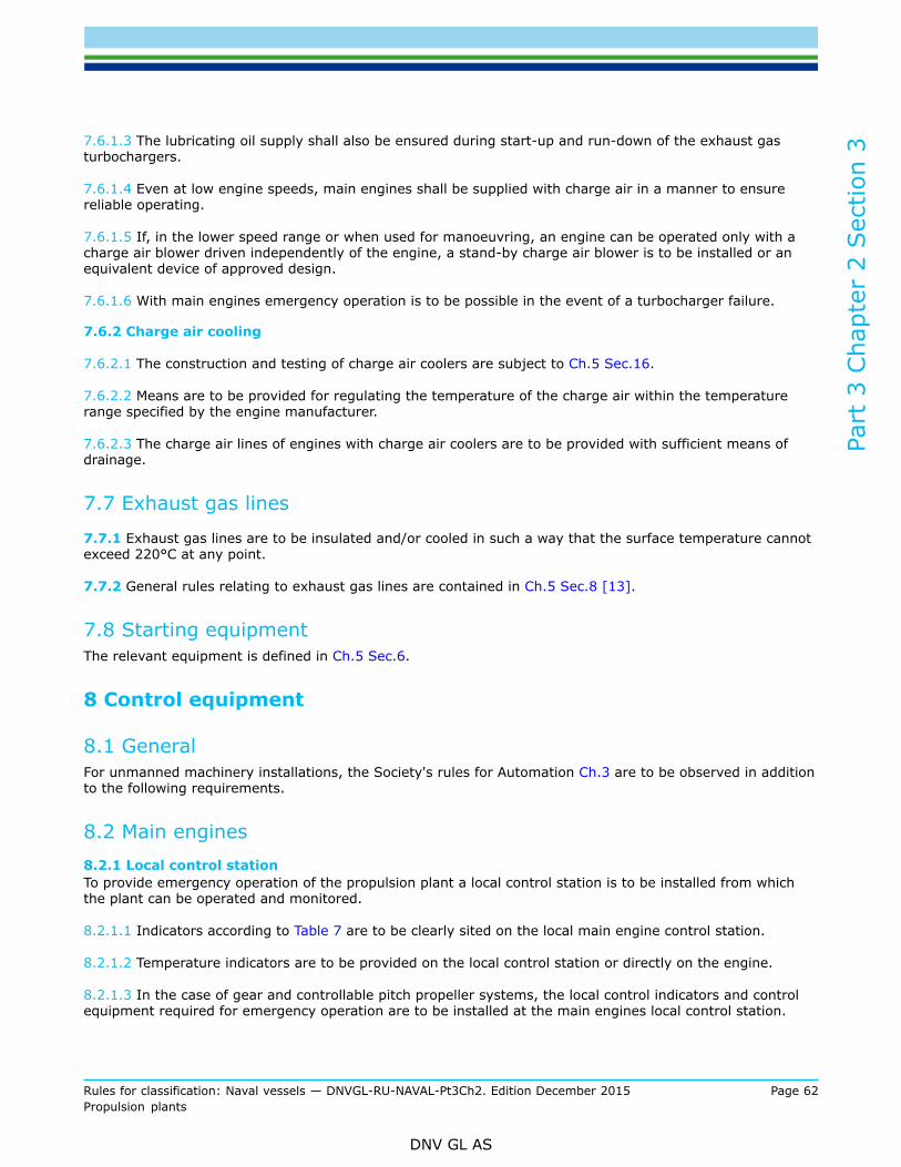
Part
3 C
hapt
er 2
Sec
tion
3
Rules for classification: Naval vessels — DNVGL-RU-NAVAL-Pt3Ch2. Edition December 2015 Page 62Propulsion plants
DNV GL AS
7.6.1.3 The lubricating oil supply shall also be ensured during start-up and run-down of the exhaust gasturbochargers.
7.6.1.4 Even at low engine speeds, main engines shall be supplied with charge air in a manner to ensurereliable operating.
7.6.1.5 If, in the lower speed range or when used for manoeuvring, an engine can be operated only with acharge air blower driven independently of the engine, a stand-by charge air blower is to be installed or anequivalent device of approved design.
7.6.1.6 With main engines emergency operation is to be possible in the event of a turbocharger failure.
7.6.2 Charge air cooling
7.6.2.1 The construction and testing of charge air coolers are subject to Ch.5 Sec.16.
7.6.2.2 Means are to be provided for regulating the temperature of the charge air within the temperaturerange specified by the engine manufacturer.
7.6.2.3 The charge air lines of engines with charge air coolers are to be provided with sufficient means ofdrainage.
7.7 Exhaust gas lines
7.7.1 Exhaust gas lines are to be insulated and/or cooled in such a way that the surface temperature cannotexceed 220°C at any point.
7.7.2 General rules relating to exhaust gas lines are contained in Ch.5 Sec.8 [13].
7.8 Starting equipmentThe relevant equipment is defined in Ch.5 Sec.6.
8 Control equipment
8.1 GeneralFor unmanned machinery installations, the Society's rules for Automation Ch.3 are to be observed in additionto the following requirements.
8.2 Main engines8.2.1 Local control stationTo provide emergency operation of the propulsion plant a local control station is to be installed from whichthe plant can be operated and monitored.
8.2.1.1 Indicators according to Table 7 are to be clearly sited on the local main engine control station.
8.2.1.2 Temperature indicators are to be provided on the local control station or directly on the engine.
8.2.1.3 In the case of gear and controllable pitch propeller systems, the local control indicators and controlequipment required for emergency operation are to be installed at the main engines local control station.
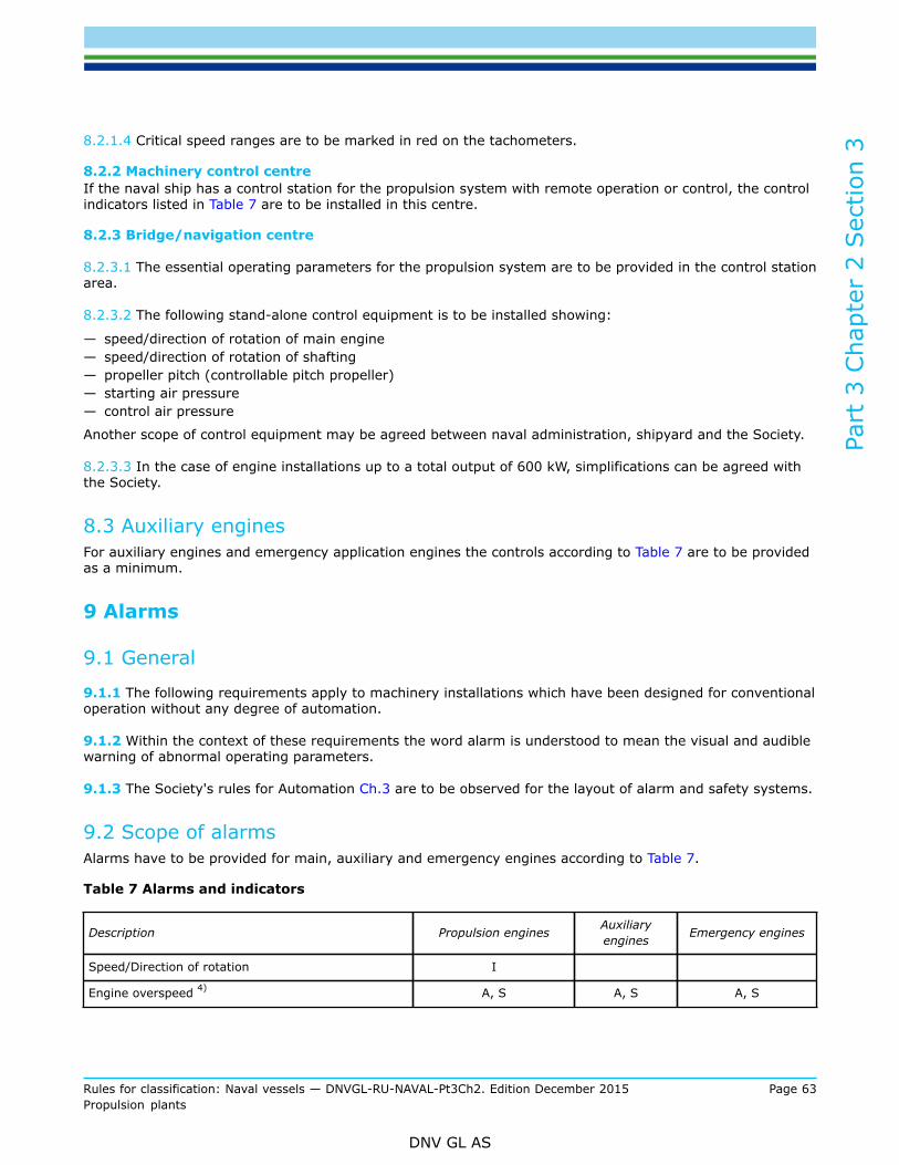
Part
3 C
hapt
er 2
Sec
tion
3
Rules for classification: Naval vessels — DNVGL-RU-NAVAL-Pt3Ch2. Edition December 2015 Page 63Propulsion plants
DNV GL AS
8.2.1.4 Critical speed ranges are to be marked in red on the tachometers.
8.2.2 Machinery control centreIf the naval ship has a control station for the propulsion system with remote operation or control, the controlindicators listed in Table 7 are to be installed in this centre.
8.2.3 Bridge/navigation centre
8.2.3.1 The essential operating parameters for the propulsion system are to be provided in the control stationarea.
8.2.3.2 The following stand-alone control equipment is to be installed showing:
— speed/direction of rotation of main engine— speed/direction of rotation of shafting— propeller pitch (controllable pitch propeller)— starting air pressure— control air pressure
Another scope of control equipment may be agreed between naval administration, shipyard and the Society.
8.2.3.3 In the case of engine installations up to a total output of 600 kW, simplifications can be agreed withthe Society.
8.3 Auxiliary enginesFor auxiliary engines and emergency application engines the controls according to Table 7 are to be providedas a minimum.
9 Alarms
9.1 General
9.1.1 The following requirements apply to machinery installations which have been designed for conventionaloperation without any degree of automation.
9.1.2 Within the context of these requirements the word alarm is understood to mean the visual and audiblewarning of abnormal operating parameters.
9.1.3 The Society's rules for Automation Ch.3 are to be observed for the layout of alarm and safety systems.
9.2 Scope of alarmsAlarms have to be provided for main, auxiliary and emergency engines according to Table 7.
Table 7 Alarms and indicators
Description Propulsion engines Auxiliaryengines Emergency engines
Speed/Direction of rotation I
Engine overspeed 4) A, S A, S A, S

Part
3 C
hapt
er 2
Sec
tion
3
Rules for classification: Naval vessels — DNVGL-RU-NAVAL-Pt3Ch2. Edition December 2015 Page 64Propulsion plants
DNV GL AS
Description Propulsion engines Auxiliaryengines Emergency engines
Lubricating oil pressure at engine inlet I, L 8), S I, L 8), S I, L 8)
Lubricating oil temperature at engine inlet I, H I 4), H 4) I 4), H 4)
Fuel oil pressure at engine inlet I I
Fuel oil leakage from high pressure pipes A A A
Cooling cylinder water pressure at engine inlet I, L I 3), L 3) I 3), L 3)
Cooling cylinder water temperature at engine outlet I, H I, H I, H
Charge air pressure at cylinder inlet I
Charge air temperature at charge air cooler inlet I
Charge air temperature at charge air cooler outlet I, H
Starting air pressure, if applicable I, L
Control air pressure I, L
Exhaust gas temperature 1) I, H 2)
Oil mist concentration in crankcase or alternativemonitoring system 5), 6) , 7) I, H I, H I, H
— A: Alarm— H: Alarm for upper limit— I: Indicator— L: Alarm for lower limit— S: Shut-down
1) where ever the dimensions permit, at each cylinder outlet and at turbocharger inlet and outlet2) at turbocharger outlet only3) cooling water pressure or flow,4) only for an engine output ≥ 200 kW,5) for engines having an output limit > 2250 kW or a cylinder bore 300 mm,6) alternative methods of monitoring may be approved by the Society,7) an engine shut-down may be provided where necessary,8) Only for an engine output > 37 kW
10 Engine alignment/seating
10.1 Engines are to be mounted and secured to their foundations in conformity with RU SHIP Pt.4 Ch.2 Sec.1 [6].
10.2 The crankshaft alignment is to be checked every time an engine has been aligned on its foundation bymeasurement of the crank web deflection and/or other suitable means.For the purpose of subsequent alignments, note is to be taken of:
Part
3 C
hapt
er 2
Sec
tion
3
Rules for classification: Naval vessels — DNVGL-RU-NAVAL-Pt3Ch2. Edition December 2015 Page 65Propulsion plants
DNV GL AS
— the draught/load condition of the ship— the condition of the engine - cold/preheated/hot
10.3 Where the engine manufacturer has not specified values for the permissible crank web deflection,assessment by the Society's will be carried out on a case-by-case basis.
11 Exhaust gas cleaning systems
11.1 GeneralIf naval ships shall be equipped with exhaust gas cleaning systems these should comply with the applicablestatutory requirements like the MARPOL Convention. In case of wet exhaust gas cleaning systems (scrubbersystems) IMO Resolution MEPC.184(59) applies.
11.1.1 ApplicationThe following requirements apply to exhaust gas cleaning systems which reduce the amount of nitrogenoxides (NOx), sulphur oxides (SOx) or particulate matter from the exhaust gases of internal combustionengines, incinerators or auxiliary steam boilers.
11.2 ApprovalWhere an exhaust gas cleaning system is installed details of the arrangement and a description of thefunction are to be submitted to the Society for approval.
11.2.1 Documents for approvalFor approval, drawings showing the main dimensions of the systems shall be submitted includingdocumentation concerning installation requirements and operational features. An operating manual shallinclude instructions for emergency operation, if applicable.
11.2.2 Approval CertificateAfter successful appraisal of the required documents and successful conclusion of the shipboard test inpresence of a surveyor the Society issues an Approval Certificate.
11.3 Layout11.3.1 System layout and installationExhaust gas cleaning systems shall be independent for each combustion engine or combustion plant. Generalrequirements on the use of combustible materials and on structural fire protection are to be observed.Thermal expansion of the system and its mechanical connections to both the ship’s structure and the exhaustpipes has to be considered. The requirements for exhaust gas lines set out in Ch.5 Sec.8 [13] shall be takeninto account. The after treatment system is to be equipped with at least one inspection port.Exhaust gas cleaning systems are to be accessible for inspection and maintenance. A change or removal ofinternal components shall be possible, where applicable.
11.3.2 BypassWhere an exhaust gas cleaning system is installed with a single main propulsion engine a bypass, controlledby flap valves or other suitable cut-off devices, is required in order to allow unrestricted engine operation incase of system failure. The bypass shall be designed for the maximum exhaust gas mass flow at full engineload.

Part
3 C
hapt
er 2
Sec
tion
3
Rules for classification: Naval vessels — DNVGL-RU-NAVAL-Pt3Ch2. Edition December 2015 Page 66Propulsion plants
DNV GL AS
In case of an exhaust gas cleaning system installed on an engine of a multi engine plant a bypass systemmay be dispensed with.
11.3.3 Additional pressure lossThe total pressure loss in the exhaust gas system, including the additional pressure loss from the exhaustgas cleaning system, shall not exceed the maximum allowable exhaust gas back pressure as specified by theengine manufacturer at any load condition.
11.3.4 Maximum gas pressureThe maximum pressure in the system of the exhaust pipes as specified by the manufacturer shall not beexceeded. Care is to be taken in particular where the exhaust gas cleaning system is located upstream of theturbocharger of the combustion engine.
11.3.5 Oscillation characteristics of the exhaust gas columnThe installation and operation of the exhaust gas cleaning system shall not have an adverse effect on theoscillation characteristics of a combustion engine’s exhaust gas column in order to avoid unsafe engineoperation.
11.3.6 Deposition of sootThe deposition of soot within or in the proximity of the exhaust gas cleaning system should be avoided.Where this may lead to additional fire hazards the deposition of soot is not acceptable.
11.3.7 Vibrations in piping systemThe design and installation of the exhaust gas cleaning system including the exhaust gas piping systemshall account for vibrations induced by the ship’s machinery, the pulsation of the exhaust gas or vibrationstransmitted through the ship’s structure in order to prevent mechanical damage to the piping system.Consideration should be given to the installation of damping systems and/or compensators.
11.3.8 Monitoring of the operating parametersThe main operating parameters of the exhaust gas cleaning system have to be monitored and shouldserve as indicators for possible abnormalities. As a minimum, the following operating parameters shall bemonitored:
— gas temperature upstream of the exhaust gas cleaning system— gas temperature downstream of the exhaust gas cleaning system— pressure drop across the exhaust gas cleaning system— engine exhaust gas back pressure— position of flap valves
11.4 MaterialsAll materials of the exhaust gas cleaning system, connecting pipes and chemically reactive agent dosing unitsshall be non-combustible. The requirements relating to exhaust gas lines as contained in Ch.5 Sec.8 [13] areto be observed, as applicable.
11.5 Chemically reactive agents11.5.1 Reducing agentFor Selective Catalytic Reduction (SCR) type exhaust gas cleaning systems the reducing agent (Ammonia,dissolved Ammonia, Urea or the like) has to be stored and pumped in tanks and pipes made of approvedmaterials for these types of agents, see Ch.5 Sec.8 [13].
11.5.2 Ammonia slipWhere Selective Catalytic Reduction (SCR) type exhaust gas cleaning systems are applied, excessive slip ofammonia has to be prevented.

Part
3 C
hapt
er 2
Sec
tion
3
Rules for classification: Naval vessels — DNVGL-RU-NAVAL-Pt3Ch2. Edition December 2015 Page 67Propulsion plants
DNV GL AS
11.5.3 Washwater criteriaWhere the exhaust gases are washed with water, discharged wash water has to comply with criteria asspecified in IMO Resolution MEPC.184(59).
11.6 Shipboard testingThe exhaust gas cleaning and bypass system is subject to inspection and functional tests in each case in thepresence of a surveyor.

Part
3 C
hapt
er 2
Sec
tion
4
Rules for classification: Naval vessels — DNVGL-RU-NAVAL-Pt3Ch2. Edition December 2015 Page 68Propulsion plants
DNV GL AS
SECTION 4 THERMAL TURBOMACHINERY GAS TURBINES
1 General
1.1 Application
1.1.1 Gas turbines on naval ships for the applications
— essential main propulsion— non-essential propulsion— driving of auxiliaries
as defined in [1.2] are subject to these rules. According to the special purpose of the type of naval ship, theyare to be designed, constructed, tested, certified and installed on board in accordance with the requirementsof this Section.
1.1.2 Gas turbines installed on the Society classed ships and not fulfilling purposes as described under[1.1.1] are not subjected to the rules of this Section. They have nevertheless to fulfil all requirements relatedto passive safety (fire protection, containment, safety devices for rendering to a safe state after malfunctionor failure of components).
1.1.3 Gas turbines with a power less than 500 kW are not required to comply with the rules of this Section,but have to be designed, constructed and equipped in accordance to good practice for marine applications.
1.1.4 Acceptance is based on test bed results for a prototype (manufacturer´s documentation) andsuccessful performance test after installation in presence of a surveyor. Further documentation may berequested for appraisal purposes upon agreement between the Society, manufacturer and shipyard.
1.1.5 Subject to approval is the complete gas turbine plant including foundation, piping, fuel, lubrication,cooling as well as safety, control, monitoring and alarm systems. The rules of this Section, especially forplants as described under [1.1.1], apply for the gas turbine unit itself, as well as for the complete installation.Typically the gas turbine unit with manifold integrated feeding systems, internal clutches, combustionchambers, etc. is subject to type approval, the installation, connection and foundation of the completemanifold on the ship´s side are project specific.So far the gas turbine type/version has been subjected to a type approval, the relevant drawings are tobe submitted, so far project related and therefore not covered up by the type approval (see [1.3.3] and[1.3.4]). Responsible for submission of the installation drawings on the ship is the contractual partner of theSociety during the building phase.
1.2 DefinitionsThe following definitions are to be applied:
1.2.1 Essential main propulsionThe gas turbine serves as exclusive drive for the propulsion elements and is essential for the safety andmanoeuvrability of the ship.
1.2.2 Non-essential propulsionOther propulsion drives, e.g. internal combustion engines or other gas turbines, secure the safety andmanoeuvrability of the ship and the gas turbine in question is only temporarily used as booster to achievemaximum ahead speed.

Part
3 C
hapt
er 2
Sec
tion
4
Rules for classification: Naval vessels — DNVGL-RU-NAVAL-Pt3Ch2. Edition December 2015 Page 69Propulsion plants
DNV GL AS
1.2.3 Driving of auxiliariesThe gas turbine is not directly involved in the propulsion of the ship, but drives a generator or other auxiliaryunits of the machinery systems.
1.2.4 Maximum permissible power (type related)The maximum permissible power is the maximum power of the applied type of gas turbine in the actualupgrade version, independent of project dedicated application. This is the base for design calculations andtype approval procedure.
1.2.5 Maximum continuous rating (project related)Maximum continuous rating means 100% gas turbine power (MCR condition). The gas turbine is to be limitedto the specified maximum continuous rating after performance test in the manufacturer’s facilities and/oronboard after installation.This rating is the relevant power for dimensioning of the driven devices, such as gear box, shaftings, etc. fora specific application.
1.3 Documents for approval1.3.1 GeneralDesign drawings of gas turbines are to be submitted to the Society for approval. The drawings shall containall the details necessary to carry out an examination in accordance with the following requirements.
1.3.2 Gas turbine unit (manifold)The following drawings are to be supplied by the gas turbine manufacturer within the type approvalprocedure:
— general arrangement drawing of complete manifold with manufacturer´s term definitions— assembly and sectional drawings— rotor assembly drawings including general dimensions and materials— detailed drawings of rotating parts (turbine and compressor, discs, shaftings, blades for gas generator and
power turbine, including dimensions, materials and treatment (coating, heat treatment, etc.)— casings— containment calculations for the failure mode "blade loss", so far available. This may be replaced by
documented experimental data for a prototype of the gas turbine. Instead also experimental verificationof integrity at higher speeds than 115% · nrated may be accepted (for existing and proven designs).
— bearings, thrust bearing arrangement— sealing system— combustion chambers including burners with dimensions and materials— foundation and fastening (frames)— material specifications including their mechanical and chemical properties for the rotating parts,
combustor and casing.
1.3.3 Gas turbine systems (partly manifold integrated, partly project specific)The majority of the following documents are to be adapted to the needs of the specific project and may benot part of the type approval hold by the gas turbine manufacturer.
— general arrangement drawing of complete system with block indication and technical nomenclature(Schematic indication of gas turbine unit with all connections to the feeding / controlling systems)
— arrangement within engine room with fire and safety details (location of doors, fans, fire dampers,materials and insulation, location of electrical and control panels)
— documentation of starting system with arrangement drawings, capacity data, a proof of capability toperform the required start attempts, starting logic and set points
— drawings of the fuel system including piping, instrumentation diagrams, purification and filteringequipment, specification of fuel as required by the turbine manufacturer

Part
3 C
hapt
er 2
Sec
tion
4
Rules for classification: Naval vessels — DNVGL-RU-NAVAL-Pt3Ch2. Edition December 2015 Page 70Propulsion plants
DNV GL AS
— specification of the fuel metering valve including material specification, flow rates, control parameter andinstrumentation, calibrating process
— shielding of fuel oil system piping— lubrication system in form of schematic piping diagrams, including pumps, valves, tanks, indicators,
filtering equipment, etc.— drawings shall indicate maximum and minimum pressure and temperature in the system (idling and MCR
values)— type of recommended lubricating oil and approved list of lubricants— maximum permissible amount of water in the oil— control oil system— air-intake and exhaust gas system (including filtration and silencer system)— bleed / cooling / seal air system— heat balance and design of the cooling air system to be documented on a separate drawing indicating the
maximal/minimal flow rates, the corresponding pressures of cooling air and design temperatures at ratedpower / speed of the power turbine.
— water wash system – blade cleaning system— appended manifolds including gears, clutches, couplings— fire protection system. Complete documentation of fire safety procedures e.g. type and capacity of fire
extinguishing medium, location and specification of fire (flame) detection, specification of control systemaction sequences
— foundation and fastening (frames to the ship´s structures, resilient mountings if applicable)— electrical installations, instrumentation, alarms, safety system— governor arrangement/system— Failure Mode and Effect Analysis (FMEA) for the control system (extent to be agreed upon individually
between manufacturer and the Society)
1.3.4 Design data for a specific projectFor each specific project related application of gas turbines the following basic design data has to bespecified:
— maximum continuous power, corresponding speed for gas generator and power turbine (project related)— maximum permissible rates (limitation for project, but in any case lower than maximum permissible
power as per type approval)— rated power turbine inlet temperature (and limit)— rated compressor discharge temperature (and limit) permissible (tolerable) combustor outlet temperature
deviation— maximum intake air temperature at which rated power can be achieved (to be not less than 15°C)— balancing data sheet (minimum requirements)— scheme with moment of inertias and stiffnesses, so far applicable, of rotating parts— schedule and description of the intended performance test (FAT = Factory Acceptance Test) with list of
parameters to be registered and documented.
1.3.5 MaintenanceA plan is to be submitted to the Society specifying the time intervals and extent of works for plannedmaintenance.In case of Continuous Machinery Survey agreement the maintenance scheme shall be adapted accordingly.
1.4 References to further rules1.4.1 Other rules and regulations
— DIN ISO 1940: Mechanical vibration – Balance quality requirements for rotors in a constant (rigid) state— ISO 2314: Gas turbines – Acceptance tests

Part
3 C
hapt
er 2
Sec
tion
4
Rules for classification: Naval vessels — DNVGL-RU-NAVAL-Pt3Ch2. Edition December 2015 Page 71Propulsion plants
DNV GL AS
— DIN 86009: Exhaust gas lines on ships; steel tubes
1.5 CertificationIf the requirements of this Section are met and the type tests defined in [6.2.3] were carried outsuccessfully, a Type Approval Certificate will be issued. For further gas turbines of the same type andapplications mentioned under [1.1] work’s tests (FAT) as defined in [6.2.4] shall be carried out and aCertificate will be issued.
2 Materials
2.1 Gas turbine materials have to fulfil the requirements specified by the operating conditions for the individualengine component. In the choice of materials the effects of creep, thermal fatigue, oxidation and corrosion,to which the different components of the gas turbine unit are exposed, have to be considered.
2.2 For materials the information about suitability of mechanical properties such as chemical composition, yieldstrength, elongation, fatigue properties as well as the applied heat treatment is required. Where compositematerial is used, their manufacturing procedures are to be specified.For the turbine blades only corrosion and heat-resistant materials are to be applied.
2.3 The production procedures including welding are to be qualified according to a recognised standard or therelevant rules of the Society.
2.4 For welding seams full details as filler metal particulars, heat treatment after welding and NDT for highstress seams are required and welding procedure specifications shall be included in the submitted, relevantdrawings.
2.5 For the air pipes steel or another equivalent material has to be used. Flexible connections / hoses have to benon-flammable.
2.6 As material for exhaust gas pipes heat-resistant steel has to be used. The choice of the steel type has toconsider the operation temperatures and the corrosion resistance, see also DIN 86009.
2.7 Pipes and fittings are to be manufactured from stainless steel.

Part
3 C
hapt
er 2
Sec
tion
4
Rules for classification: Naval vessels — DNVGL-RU-NAVAL-Pt3Ch2. Edition December 2015 Page 72Propulsion plants
DNV GL AS
3 Design and construction
3.1 GeneralThe gas turbine design shall be suitable for marine application and enable the full manoeuvrability of theship.Gas turbines shall be designed to permit fast start-up from cold conditions. Further possibilities are to beprovided enabling manual re-start despite control system constraints after acknowledgement of the cause oftripping or start failure.Gas turbines shall be designed for minimum times between overhauls (TBO) of > 1000 running hours. So farclassified as unique main propulsion unit, the gas turbine is expected to operate without major interruptions.The machinery class intervals, if relevant, shall be adapted in such case to the required planned maintenancescheme of the propulsion system.
3.2 BladesA blade strength calculation for the maximum permissible output/speed shall be submitted by means offinite element analysis (FEM) or other sound engineering methods for review. The following loads shall betaken into account: centrifugal and axial forces, gas pressure as well as thermal loads. The calculations maycontain the design equivalent full load operation hours or (if applicable) the assumed load profile.Cleaning equipment is to be provided during gas turbine operation for removal of blade deposits fromcompressor and turbine.
3.3 Rotor AssemblyEach shaft as well as the complete rotating assembly of compressor and turbine has to be individuallydynamically balanced in accordance with the approved quality control procedure. The balancing specificationand the results of the balancing procedure are subject of the documentation in accordance to [1.3.4]. Therequirements as set out in DIN ISO 1940 apply, specifically class G2.5 or equivalent standards.
3.4 Casing
3.4.1 A blade or impeller loss may not result in casing penetration and consequential loss of othercomponents, injury or other hazardous conditions for the ship.Casing integrity has to be maintained in case of blade loss at the most critical speed but not higher than115% of the rated speed, which is to be demonstrated by containment calculations or other methods.
3.4.2 The casing shall have sufficient openings to enable boroscope inspection of the combustor as well asfor the compressor´s and turbine´s individual stages.
3.5 Burners and combustors
3.5.1 Fuel nozzles are to be removable without disassembly of the combustor system.Regarding burners the following parameters are to be observed:
— maximum/minimum temperature and supply pressure of fuel— maximum mass flow rate of the fuel and the expected air flow (fuel/air ratio)
The burner lifetime shall be specified as well as the recommended replacement / maintenance intervals.

Part
3 C
hapt
er 2
Sec
tion
4
Rules for classification: Naval vessels — DNVGL-RU-NAVAL-Pt3Ch2. Edition December 2015 Page 73Propulsion plants
DNV GL AS
3.5.2 The combustor shall have a dual ignition system. During operation the igniters shall not be exposed tothe high temperatures of the primary combustion zone.
3.5.3 Optical and/or thermal flame sensors shall enable inspection of the flame during operation.
3.6 Adjustable vanes
3.6.1 So far the compressor air flow is controlled by means of variable guide vanes (VGV), inlet guide vanes(IGV) or/ and variable stator vanes (VSV) the corresponding mass flow charts over the guide vane angle /travel have to be indicated in the form of a chart or table.
3.6.2 The actuator is to be designed in a way to be capable to operate the adjusting mechanism of the vanesunder all conditions. Corresponding charts / tables shall be available on request.
3.7 Internal air cooling systemThe design shall be such to enable an adequate air flow capacity to keep the temperature in the powerturbine safely within the design limits under full load conditions.
3.8 Bleed valves
3.8.1 The arrangement of bleed valves shall be documented in a drawing, indicating their position and size.The associated (maximal) power loss of the turbine shall be specified for the maximal flow rates of the bleedvalves.
3.8.2 In case that bleed air is used for anti-icing purposes, this system and its associated technicalparameters such as flow rate, supply pressure, maximum air temperature and simplified heat balance, shallbe submitted for information purposes.
3.9 Bearings
3.9.1 Bearings are generally to be designed in accordance to the manufacturer's standards for loadsresulting from the turbine's full output operation for an adequate life time (compare [1.1]). They are to beequipped with adequate, replaceable sealing devices and shall be reliably lubricated to withstand also shorttime operation under normal or exceptional transient conditions, such as shut-down due to trip, blackout, etc.
3.9.2 Vibration monitoring for the bearing condition may be required by the Society, depending on theapplication.
3.10 Gas turbine enclosure
3.10.1 The enclosure shall include a system for fire detection and automatic fire extinguishing.
3.10.2 The enclosure ventilation or cooling air of the gas turbine shall be supplied from redundant fans withseparated electrical power supply.The distribution of ventilation air shall ensure that an acceptable temperature profile of the gas turbine ismaintained, and that any local accumulation of combustible gas mixtures is prohibited.In case of emergency, closing of the ventilation ducts of the plant shall be feasable in a controlled way andwithin short time, avoiding further damages due to local overheating.

Part
3 C
hapt
er 2
Sec
tion
4
Rules for classification: Naval vessels — DNVGL-RU-NAVAL-Pt3Ch2. Edition December 2015 Page 74Propulsion plants
DNV GL AS
3.10.3 The enclosure shall be equipped with at least two exits, arranged on opposite sides of the enclosure.The exits shall provide an easy escape from all relevant positions inside the enclosure.Interlocks on doors shall be provided to ensure that fire extinguishing medium hazardous to personnel is notreleased, when personnel are inside the enclosure.A gas turbine start is to be interlocked when personnel are inside the enclosure and the enclosure doors areopen. During operation the doors have to be locked.
3.10.4 If NBC protection of the machinery rooms is required the air pressure in the enclosure should be keptlower by not less than 0.5 hPa (0.5 mbar) than the pressure in the machinery room.
3.11 Fire safety
3.11.1 In addition to the machinery room fire fighting system, an approved automatic fire extinguishingsystem is to be provided for each gas turbine enclosure.Enclosure ventilation ducts are to be automatically closed when a confirmed fire is detected.
3.11.2 Inside of enclosure four flame detectors shall be arranged at different locations. A type approval isrequired for flame detectors.Detected fire in enclosure or engine room has to release an alarm and automatic cut off of the fuel supply.
3.11.3 The accumulation of flammable fluid inside of enclosure bottom has to be prevented by draining.
3.11.4 Purging of all internal gas turbine parts is required in order to discharge liquid or gaseous fuel beforeignition. Purging shall be automatically initiated for an adequate time before ignition signal is released.
3.11.5 Where surface temperatures exceed 220°C, insulation of oil non-absorbent material has to beapplied. In case that the insulation material may be penetrated by fuel, it is to be additionally shielded bysheet steel or equivalent.
3.12 Starting systems
3.12.1 The starting system, electrically, pneumatically or hydraulically driven, shall have redundancyregarding technical design and physical arrangement. A redundancy of starting system is not required ifredundant propulsion gas turbines are available each one with its own starting systems. The same appliesfor turbines installed in plants in combination with other power units for back up, such as diesel engines orelectric motors.
3.12.2 The capacity of the starting system is to be designed in order to enable six (6) consecutive startsof gas turbines for essential main propulsion duties (controllable pitch propellers or other device enablingthe start without opposite torque) respectively three (3) consecutive starts of gas turbines for non-essentialpropulsion and driving of auxiliaries. The recovery time of the starting system depends on minimum timeavailable between start attempts based on starting and control cycles.
3.12.3 Prior to ignition process, automatic purging is required for all starts and restarts. The purge phase isto be of sufficient duration in order to remove all the accumulated fuel.
3.12.4 The starting control system is to be fitted with ignition detection devices. If light-off will not beachieved within a preset time, the control system has to abort the ignition automatically, shut-off the mainfuel valve and release a purge cycle.
3.12.5 The start system shall have its own protective system to ensure prevention of damage due tooverspeed or failure to reach ignition speed.The starting system is to be protected prior to mechanical and electrical overload.

Part
3 C
hapt
er 2
Sec
tion
4
Rules for classification: Naval vessels — DNVGL-RU-NAVAL-Pt3Ch2. Edition December 2015 Page 75Propulsion plants
DNV GL AS
3.13 Lubricating oil system
3.13.1 For multiple gas turbine arrangements each turbine shall be supplied by a separate and independentlubrication oil system.
3.13.2 Bearing lubrication may not be impaired by hot gases or by adjacent hot components.
3.13.3 The lubricating oil system has to be equipped with sufficient means for filtering, heat exchange,magnetic chip detection and water separation in accordance to usual marine practice.The lubrication equipment of a gas turbine is to be arranged and protected in a way, that in case of leakagethe lubricating oil will not be spoiled over surfaces with a temperature of above 220°C and will not reach anyrotating parts.The lubricating oil system has to be equipped with a filter device, for which cleaning is possible withoutinterruption of operation of the turbine. For redundant plants and other applications as described under[3.12.1] double filters are not required. The condition of the filter (s) is to be monitored by indication of thepressure difference or other adequate means. Tanks are to be equipped with oil stand indications combinedwith a low level alarm. Re-filling of oil shall be possible without interrupting the operation. Means for takingof representative samples for analysis purposes are to be provided.
3.13.4 Especially in case of application of synthetic lubricants attention shall be given to the compatibilityto the materials of sealing arrangements and heat exchangers. Leakages within heat exchangers should notlead rapidly to a total contamination of the lubrication oil.
3.14 Fuel oil systemsGaseous fuel or combined gas / liquid fuel is excluded for the scope of these rules.
3.14.1 Fuel nozzles are to be replaceable as complete units without requirement of major adjustments worksafter replacement.
3.14.2 The system is to be equipped with suitable drain facilities for the fuel manifold and fuel nozzle tosafely handle excessive fuel originating from shutdown (normal and emergency) of the engine fuel system.
3.14.3 The combustors are to be equipped with a separate drainage system, preventing accumulation of fuelafter a failed start.
3.14.4 The day tank for the fuel supply of the gas turbine shall have adequate capacity referenced to theship´s destination and the purpose of installation of a gas turbine for essential main propulsion. The day tankhas to contain fuel in accordance to the specifications of the gas turbine maker adequately conditioned forimmediate use.
3.15 Turning gearEssential main propulsion turbines are to be equipped with turning gear both for the gas generator as well asfor the power turbine.The rotors of turbines for driving of auxiliaries shall at least be capable of being turned by hand.
3.16 Emergency operation
3.16.1 In multi-shaft installations, further operation of at least one propulsion train has to be feasible in thecase that one train is unavailable.

Part
3 C
hapt
er 2
Sec
tion
4
Rules for classification: Naval vessels — DNVGL-RU-NAVAL-Pt3Ch2. Edition December 2015 Page 76Propulsion plants
DNV GL AS
3.16.2 In single-shaft installations with two or more essential main gas turbine driving units, care is to betaken to enable further propulsion on a reduced power level, in the event of failure or unavailability of oneof the gas turbines. Each gas turbine is to be designed in a way to be able to drive the shaft on a reducedpower level, still enabling at least secure manoeuvring of the ship.
3.16.3 In the case of single-shaft installations with only one essential main gas turbine, special provisionsare to be met in agreement with the Society to ensure additional adequate redundancy on the level ofcomponents / systems.
4 Control and monitoring
4.1 Control logic
4.1.1 Gas turbines are to be installed with a type approved control and monitoring system.
4.1.2 The control logic shall include the following:
— monitoring of relevant operational parameters for control purposes, such as vibration, temperature,speed, etc. including limits and set points
— normal and emergency stop and start sequence— load control— fuel control for normal running— fuel control for shut-down— alarms and shut-down— automatic purge cycle— other systems (auxiliary supply systems and safety systems)— override functions
4.1.3 A Failure Mode and Effect Analysis (FMEA) is required for the verification of the logical interconnectionswithin the control system of gas turbines for essential main propulsion. Single failure of any system or controlduring operation at any mode shall not lead to loss of control of safety related properties of the ship, e.g. lossof control of propulsion, manoeuvrability for propulsion units, loss of electrical supply for auxiliary turbines,etc. Safe operation of the ship is to be demonstrated within the FMEA after partly or complete failure ormalfunction of a gas turbine unit, subjected to these rules.
4.2 Operation characteristics4.2.1 AutomationAutomation shall be used to simplify operation and control and exclude operational mistakes by an automaticinitiation of procedures operationally connected to each other. In addition automation shall enable acentralised handling and control of the propulsion plant. The equipment for local manual hand-ling andcontrol has to exist to a full extent independently from the degree of automation.The procedures to prepare the ship for sea shall not be included in the automation.
4.2.2 StartingStart-up shall take place automatically in a defined sequence. Interlocks are to be provided to ensure thatthis sequence (attainment of ignition speed, ignition, flame monitoring) is followed.Starting sequence is to be disconnected and main fuel valve to be closed within a pre-determined time, whenignition has failed.The purging mode is to be integrated in the control system both for normal start-up as well as after startfailure. The duration of required purging should normally be sufficient to displace the exhaust system volumethree times before attempting re-start.

Part
3 C
hapt
er 2
Sec
tion
4
Rules for classification: Naval vessels — DNVGL-RU-NAVAL-Pt3Ch2. Edition December 2015 Page 77Propulsion plants
DNV GL AS
4.2.3 Speed control
4.2.3.1 Gas turbines within the scope of these rules are to be fitted with a speed governor which, in theevent of a sudden load drop, prevents the revolutions from increasing to the trip speed.
4.2.3.2 The speed increase of gas turbines driving electric generators subsequent to a load drop from 100%to idling may not exceed 10% of the nominal speed and shall return to the steady state with a maximaldeviation of 5% of the nominal value within 2 s. The transient increase shall in any case remain safely withinthe overspeed margin.
4.2.3.3 Gas turbine control systems are to be provided with overspeed protection preventing the turbinespeed from exceeding 115% of the maximum continuous speed (project related speed).
4.2.4 The safety system has to work independently from the gas turbine control. In the case of activation ofa safety device, the gas turbine has to be blocked against a new start, before manual acknowledgement. Thedevices for de-blocking have to be arranged in a way enabling a quick re-start attempt of the gas turbine.
4.3 Control stations
4.3.1 The operation of the gas turbine shall be possible by remote control from the machinery control centre(MCC). The wiring for control purposes shall be independent and free of cross-connections to other systems.
4.3.2 An additional manual control is to be provided directly at the gas turbine´s enclosure and shall includea shut-down release. This shall interrupt the fuel supply instantaneously.Suitable operating devices have to be provided at a good accessible position.
4.3.3 The operation of the gas turbine control system shall be independent of the common ship controlsystem.
4.4 Power supplyThe control system is to be equipped with an uninterruptible power supply designed to maintain supply alsounder blackout conditions. Total loss of control system power shall lead to a controlled and safe turbineshutdown.
4.5 MonitoringAn instrumentation list showing sensor, type, set point and measuring limit for essential main propulsion gasturbines is required according to Table 1 for approval.
4.6 Further requirementsFor all equipment of control, operating and watch stands and centres the requirements of the Society's rulesfor Automation Ch.3, especially Sec.1 have to be applied. If an extended scope of the operating and controlequipment is required by the naval administration, it has to be defined in the building specification.

Part
3 C
hapt
er 2
Sec
tion
4
Rules for classification: Naval vessels — DNVGL-RU-NAVAL-Pt3Ch2. Edition December 2015 Page 78Propulsion plants
DNV GL AS
Table 1 Alarms and indicators for essential main propulsion gas turbines
Signal
F = Fault
L = Low limit
H = High limit
S = Shut-down
IndividualAlarm
Indication
GroupAlarm
IndicationShut-down
Fuel temperature H
Fuel oil supply pressure L
Fuel filter, differential pressure 2) H
Level in lubrication oil sump L H
Lubrication oil pressure L L S
Lubrication oil temperature inlet H
Lubrication oil filter, differential pressure H
Cooling water temperature H
Cooling water pressure L
Compressor inlet pressureor air intake filter, differential pressure
H LH SL S
Anti-icing system failure F
Power turbine overspeed, speed sensor H H S
Failure to reach idle speed 2) F
Failure to ignite F F S
Flame out detection F F S
Power turbine inlet temperature 1) L
Exhaust temperature (power turbine outlet) H H S
Bearing temperature H
Thrust bearing temperature H
Vibration, vibration sensor (for each bearing) 3) H H S
Axial displacement of power turbine,thrust bearing value
H H S
Power loss of monitoring system F
Power loss of control system F
Loss of cooling air supply (pressure or flow) L
Starting system failure F
Fire detection inside gas turbine enclosure F F S
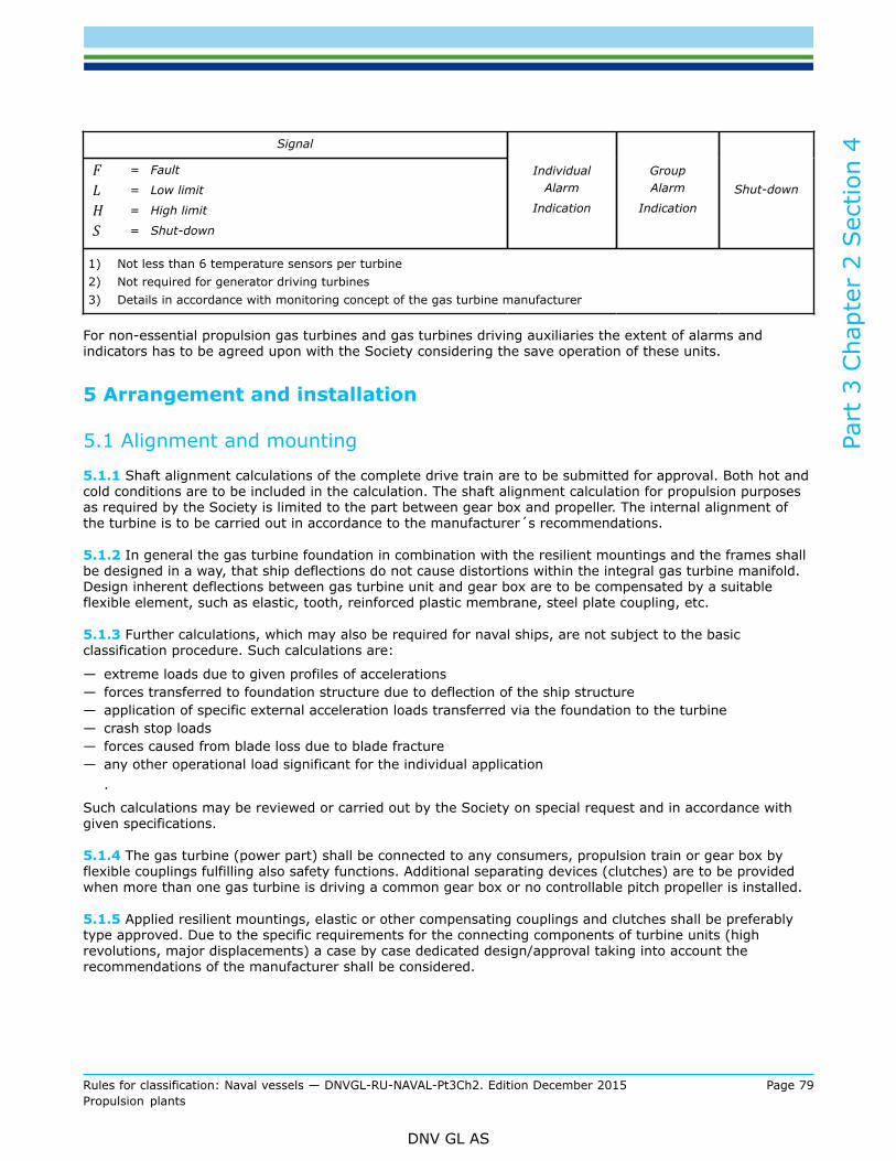
Part
3 C
hapt
er 2
Sec
tion
4
Rules for classification: Naval vessels — DNVGL-RU-NAVAL-Pt3Ch2. Edition December 2015 Page 79Propulsion plants
DNV GL AS
Signal
F = Fault
L = Low limit
H = High limit
S = Shut-down
IndividualAlarm
Indication
GroupAlarm
IndicationShut-down
1) Not less than 6 temperature sensors per turbine2) Not required for generator driving turbines3) Details in accordance with monitoring concept of the gas turbine manufacturer
For non-essential propulsion gas turbines and gas turbines driving auxiliaries the extent of alarms andindicators has to be agreed upon with the Society considering the save operation of these units.
5 Arrangement and installation
5.1 Alignment and mounting
5.1.1 Shaft alignment calculations of the complete drive train are to be submitted for approval. Both hot andcold conditions are to be included in the calculation. The shaft alignment calculation for propulsion purposesas required by the Society is limited to the part between gear box and propeller. The internal alignment ofthe turbine is to be carried out in accordance to the manufacturer´s recommendations.
5.1.2 In general the gas turbine foundation in combination with the resilient mountings and the frames shallbe designed in a way, that ship deflections do not cause distortions within the integral gas turbine manifold.Design inherent deflections between gas turbine unit and gear box are to be compensated by a suitableflexible element, such as elastic, tooth, reinforced plastic membrane, steel plate coupling, etc.
5.1.3 Further calculations, which may also be required for naval ships, are not subject to the basicclassification procedure. Such calculations are:
— extreme loads due to given profiles of accelerations— forces transferred to foundation structure due to deflection of the ship structure— application of specific external acceleration loads transferred via the foundation to the turbine— crash stop loads— forces caused from blade loss due to blade fracture— any other operational load significant for the individual application
.
Such calculations may be reviewed or carried out by the Society on special request and in accordance withgiven specifications.
5.1.4 The gas turbine (power part) shall be connected to any consumers, propulsion train or gear box byflexible couplings fulfilling also safety functions. Additional separating devices (clutches) are to be providedwhen more than one gas turbine is driving a common gear box or no controllable pitch propeller is installed.
5.1.5 Applied resilient mountings, elastic or other compensating couplings and clutches shall be preferablytype approved. Due to the specific requirements for the connecting components of turbine units (highrevolutions, major displacements) a case by case dedicated design/approval taking into account therecommendations of the manufacturer shall be considered.

Part
3 C
hapt
er 2
Sec
tion
4
Rules for classification: Naval vessels — DNVGL-RU-NAVAL-Pt3Ch2. Edition December 2015 Page 80Propulsion plants
DNV GL AS
5.2 Air inlet and exhaust gas outlet system
5.2.1 The air inlet shall be equipped with air filters in order to avoid the ingestion of dirt or harmful particlesincluding sea salt deposits to the gas turbine. The pressure drop across air filter shall be monitored andindicated in relation to the maximal permissible value.Air filter icing is to be prevented by an anti-icing system, so far required by the specific application. Thesuction of air intakes is to be arranged and designed in a way to limit intrusion of spraying water to aminimum. The air inlet shall be equipped with means to enable drainage of water.
5.2.2 Air intakes and exhaust outlet are to be arranged in a way that re-ingestion of exhaust gases isminimised.
5.2.3 Multi engine installations shall be equipped with separate inlets and outlets for each gas turbine.
5.2.4 Inlet and exhaust silencers are to be fitted, if needed, in order to limit the sound power level. Themaximal sound power at a distance of one meter from the gas turbine system shall not exceed 110 dBfor unmanned machinery spaces (typically in the gas turbine's enclosure) or 80 dB for manned machinerycontrol centres (MCC).
5.3 Vibration analysis
5.3.1 For propulsion systems driving a propeller or water jet a torsional vibration of the complete systemincluding gas turbine and propulsion train is to be submitted for approval. As main excitation for the systemthe periodical forces of the propeller / impeller may be regarded (1st and 2nd blade excitation).
5.3.2 Excitations generated by the power turbine may be neglected, unless specifically given by themanufacturer. Excitations exceeding 100 Hz can be neglected for the scope of torsional vibration calculations.
5.3.3 Further vibration analyses such as bending vibrations may be required by the manufacturer of the gasturbine. The recommendations of the manufacturer in this respect shall be applied.
6 Tests and trials
6.1 Material tests
6.1.1 Material certificates for the components as listed in Table 2 are to be supplied on request. Specialagreements related to the manufacturing procedures and suppliers have to be met on a case by case base.The extent of tests shall at least comply with the approved quality scheme of the manufacturer.
Table 2 Type of material certificate required for essential components
Component: Material Certificate 1
Blades
Impellers
Shafts
Disks
Tie bolts
The Society's Material Certificate or Manufacturer InspectionCertificate to be decided case by case by the Society dependenton the installed quality assurance system of the manufacturer
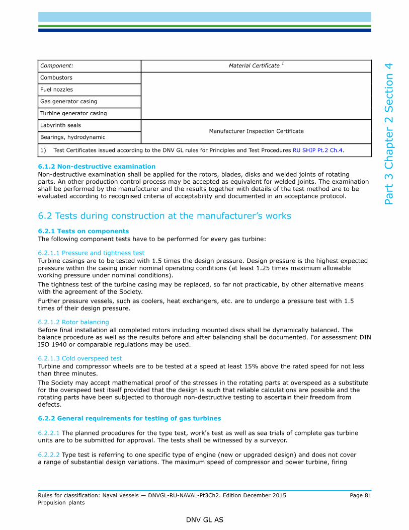
Part
3 C
hapt
er 2
Sec
tion
4
Rules for classification: Naval vessels — DNVGL-RU-NAVAL-Pt3Ch2. Edition December 2015 Page 81Propulsion plants
DNV GL AS
Component: Material Certificate 1
Combustors
Fuel nozzles
Gas generator casing
Turbine generator casing
Labyrinth seals
Bearings, hydrodynamicManufacturer Inspection Certificate
1) Test Certificates issued according to the DNV GL rules for Principles and Test Procedures RU SHIP Pt.2 Ch.4.
6.1.2 Non-destructive examinationNon-destructive examination shall be applied for the rotors, blades, disks and welded joints of rotatingparts. An other production control process may be accepted as equivalent for welded joints. The examinationshall be performed by the manufacturer and the results together with details of the test method are to beevaluated according to recognised criteria of acceptability and documented in an acceptance protocol.
6.2 Tests during construction at the manufacturer’s works6.2.1 Tests on componentsThe following component tests have to be performed for every gas turbine:
6.2.1.1 Pressure and tightness testTurbine casings are to be tested with 1.5 times the design pressure. Design pressure is the highest expectedpressure within the casing under nominal operating conditions (at least 1.25 times maximum allowableworking pressure under nominal conditions).The tightness test of the turbine casing may be replaced, so far not practicable, by other alternative meanswith the agreement of the Society.Further pressure vessels, such as coolers, heat exchangers, etc. are to undergo a pressure test with 1.5times of their design pressure.
6.2.1.2 Rotor balancingBefore final installation all completed rotors including mounted discs shall be dynamically balanced. Thebalance procedure as well as the results before and after balancing shall be documented. For assessment DINISO 1940 or comparable regulations may be used.
6.2.1.3 Cold overspeed testTurbine and compressor wheels are to be tested at a speed at least 15% above the rated speed for not lessthan three minutes.The Society may accept mathematical proof of the stresses in the rotating parts at overspeed as a substitutefor the overspeed test itself provided that the design is such that reliable calculations are possible and therotating parts have been subjected to thorough non-destructive testing to ascertain their freedom fromdefects.
6.2.2 General requirements for testing of gas turbines
6.2.2.1 The planned procedures for the type test, work's test as well as sea trials of complete gas turbineunits are to be submitted for approval. The tests shall be witnessed by a surveyor.
6.2.2.2 Type test is referring to one specific type of engine (new or upgraded design) and does not covera range of substantial design variations. The maximum speed of compressor and power turbine, firing

Part
3 C
hapt
er 2
Sec
tion
4
Rules for classification: Naval vessels — DNVGL-RU-NAVAL-Pt3Ch2. Edition December 2015 Page 82Propulsion plants
DNV GL AS
temperature, turbine inlet temperature, exhaust temperature, mass flow rates and power are typicallyfixed design values for a type of turbine. Such a list of characteristic parameters will be listed for referencepurposes in the type approval Certificate.
6.2.2.3 Every gas turbine, besides the extensively type tested prototype, shall undergo, before delivery thework’s tests (Factory Acceptance Test) according to [6.2.4] and the sea trials according to [6.4], witnessedby a surveyor and documented accordingly.
6.2.2.4 Besides the characteristic gas turbine parameters as listed in [1.3], additionally the followingparameters indicating performance and consumption under deviating ambient condition parameters shall berecorded:
— ambient air temperature— ambient air pressure— relative humidity— lower heating value for liquid or gaseous fuel— torque measured by absorption dynamometer or shaft torque meter
The measured ambient parameters as listed above shall be used in combination with the reference conditionsas listed in Table 3 for calculation of referenced values for specific fuel consumption, so far required by thenaval administration.
Table 3 Standard reference conditions according to ISO 2314
Temperature: 15°C
Humidity: 60% relative
Barometric Pressure: 1013 mbar
6.2.2.5 The monitoring and control system used during FAT (manufacturer test bed facilities) of the gasturbine manifold has to deliver equivalent and comparable parameter lists to the system´s, which will beapplied on the ship or during containerization of the manifold. Latter systems are to be approved by themanufacturer of the gas turbine and have to be type approved by the Society.
6.2.2.6 After running on the test bed, the fuel delivery system of gas turbines for propulsion is normally tobe adjusted and limited to 100% power. The fuel system for gas turbines driving generators may be limitedto a higher value, but not higher than 110% output. power. The limit value shall not exceed the "maximumpermissible power" as defined under [1.2].
6.2.3 Testing within type test procedure (FAT Prototype)
6.2.3.1 GeneralType approval of gas turbines includes an extended type test for the first gas turbine of a family. The typetest is to be carried out at the manufacturer’s facilities and is normally to be attended by a surveyor. Foralready existing and proven design a well documented and complete type test procedure performed bythe manufacturer, and attended by another independent body or recognized Classification Society may beaccepted by the Society after thorough review of the documentation.
6.2.3.2 Scope of testsThe type test has to include:
— start test— emergency shutdown test— performance test— emergency operation test
Part
3 C
hapt
er 2
Sec
tion
4
Rules for classification: Naval vessels — DNVGL-RU-NAVAL-Pt3Ch2. Edition December 2015 Page 83Propulsion plants
DNV GL AS
The test procedure is to be approved by the Society prior testing.The following tests shall be carried out preferably with the actual control system installed and fully active. Itis recommended to check the control system provisionally during type test and work´s test, but additionallyin combination with the finally installed system on the ship before or during the sea trials.
6.2.3.3 Start testThere has to be at least one false engine start simulation, followed by the manufacturer’s specified minimumfuel drainage time before attempting a normal start.Three normal restarts after an emergency shutdown are to be performed.
6.2.3.4 Emergency shut-down down testEmergency shut-down may be caused by:
— hot shut-down, at full load; restart is to be achieved before lockout and within 30 minutes.— failure to ignite, resulting in aborted start sequence— flame out
During this test the gas turbine is to accelerate to the overspeed limit (115%) in order to verify the functionof the overspeed shut-down.
6.2.3.5 Performance test (type test)6.2.3.5.1 Test sequenceThe test sequence is as follows:
— 100 hours total at different part loads and time increments between maximum continuous turbinerotational speed and minimum idle speed for propulsion applications (Propeller curve) or synchronousspeed and different loads for generator applications (Load Variation). For details see [6.2.3.5.2] and[6.2.3.5.3].
— thereof at least 1 hour total at rated maximum continuous power (100% output at 100% torque and100% speed).
— 30 min. with 110% power.
The performance test as roughly described herein and in [6.2.4] represents minimal requirements. It is takenfor granted that the manufacturer has performed long term running trials for the first engine, which aredocumented and available on request.In case that the gas turbine shall be offered for both propulsion and generator purposes, the performancetest shall include both load variation at variable speed (propeller curve) as well as constant speed. The typeapproval then covers up both applications, so far successfully contacted.6.2.3.5.2 Propulsion plantsThe performance test takes mainly reference to the 100% and 110% output. Further investigation pointsunder steady conditions shall be required in accordance to the available facilities. Commonly the 90%, 75%,50%, 25% output point at variable speed corresponding to the propeller curve shall be demonstrated anddocumented.6.2.3.5.3 Generator plantsFor generator plants further tests concerning load drop and load raise as well as part load running will berequired. This will be done on individual base, when approving the proposed test procedure, in order to takeinto account the special conditions of the specific turbine resp. manufacturer.In general for generator plants, load drop from 100% to 0%, load increase from 0% to 100% and other loadvariations due to power demand, are not to result in a transient variation in rpm higher than +/- 10%. Thepermanent speed fluctuation under stationary conditions shall not exceed +1 % of the rated speed.
6.2.3.6 Emergency operation testFor emergency operating situation, the following tests are to be performed:
— quick start

Part
3 C
hapt
er 2
Sec
tion
4
Rules for classification: Naval vessels — DNVGL-RU-NAVAL-Pt3Ch2. Edition December 2015 Page 84Propulsion plants
DNV GL AS
— override functions
The manufacturer has to demonstrate by proven experience or design calculations that this emergencyoperation will not cause malfunctions or damages to the gas turbine.
6.2.3.7 Type test reportThe gas turbine manufacturer's records including all monitored performance data shall be documented ina type test report, which is to be submitted for approval. In case that, irregularities, such as failures ofcomponents, seizing of parts, etc., occur, the cause has to be analysed and eliminated. The report on thedamage/irregularities and the introduced countermeasures has to be part of the report.
6.2.4 Testing within work’s test procedure (FAT individual gas turbine)
6.2.4.1 GeneralEvery gas turbine of a type approved type, subject to certification in accordance to [1.5], shall undergo awork´s test in the facilities of the manufacturer before certification and delivery for installation.The work’s test procedure is to be approved by the Society prior testing.
6.2.4.2 Scope of testsThe work’s test has to include:
— start test according to [6.2.3.3]— emergency shut-down test according to [6.2.3.4]— performance work’s test according to [6.2.4.3]— emergency operation test according to [6.2.3.6]
6.2.4.3 Performance work’s testThe test sequence has to be as follows:
— 1 hour total at rated maximum continuous power, 100% output at 100% torque and 100% speed— 30 min. with 110% power— further operation at part load (totally 1h) with variable speed (for the case of essential main propulsion
turbine) or at synchronous speed (for generator applications).
For special applications such as naval craft further or "in lieu of" testing may be required and will be agreedupon between the Society and the manufacturer. This depends on the special requirements of the navaladministration.For further details see [6.2.3.5].
6.3 Boroscope inspection
6.3.1 A boroscope inspection is to be conducted after the type test according to [6.2.3] and the work's testsaccording to [6.2.4].After the type test normally the turbine unit will be disassembled and the major components will be checkedthoroughly. If such a procedure is applied, a boroscope inspection is not necessary.A boroscope inspection may be required also after sea trials, on specific demand of an involved party or ifirregularities are detected.Boroscope inspection shall be conducted or witnessed by an attending surveyor, if required by the Society.
6.3.2 Boroscope inspection of the following parts is to be conducted, if inspection ports are available:
— compressor (blades and nozzles)— combustor— fuel burners— high pressure turbine (blades and nozzles)
Part
3 C
hapt
er 2
Sec
tion
4
Rules for classification: Naval vessels — DNVGL-RU-NAVAL-Pt3Ch2. Edition December 2015 Page 85Propulsion plants
DNV GL AS
— power turbine (blades and nozzles)
6.3.3 In general no cracks or major wear shall be seen in rotating parts after testing of a new gas turbine.Minor cracks, indents or tears in uncritical parts may be accepted based on documented acceptance criteria.
6.4 Sea trials6.4.1 Trial procedureThe sea trials have to simulate the conditions in which the engine is expected to operate in service on boardof the naval ship, including typical start-stop cycles, idling, acceleration, deceleration.The sea trial procedure is to be approved by the Society prior to testing.
6.4.2 No load running, adjustmentsPrior to the start of the sea trials, the engine and the control and monitoring system are to demonstratetrouble free running at no load for 20 minutes.For generator gas turbines testing and adjustment of the load sharing characteristics, as far as applicable,are to be carried out. Such test adjustments may also be carried out in the facilities of the Generator SetMaker or during containerization.
6.4.3 Performance testAs a minimum the engine is to be run for at least 6 hours as follows:
— at least 4 hours at rated speed— at least 2 hours at engine speed corresponding to normal continuous ahead cruising speed vM
For special purpose gas turbines such as for non-essential propulsion and special considerations inaccordance with specifications of the naval administration may be applicable.
6.4.4 Special testsCrash-stop conditions shall be tested from full speed. This is to be performed in the fastest time permitted bythe controls of the gas turbine.There shall be at least one simulation of a false turbine start with the following purging time beforeattempting a normal start. Minimum time required for restart of the turbine is to be checked in order to verifythat start can be achieved before thermal interlock occurs.
6.4.5 Vibration measurementsVibration measurements are to be recorded during sea trials. The vibration signals are to be recorded forconditions taking into consideration the possible operation modii of the propulsion plant, e.g. controllablepitch propeller and constant turbine speed or fixed pitch propeller and variable turbine speed. Clutch-inprocedures, starting and stopping, etc. shall be investigated on request separately.
6.4.6 Final inspectionBoroscope inspection according to [6.3] may be required by the Society after sea trials.

Part
3 C
hapt
er 2
Sec
tion
5
Rules for classification: Naval vessels — DNVGL-RU-NAVAL-Pt3Ch2. Edition December 2015 Page 86Propulsion plants
DNV GL AS
SECTION 5 THERMAL TURBOMACHINERY / EXHAUST GASTURBOCHARGERS
1 General
1.1 ScopeThe following rules apply to the requirements for exhaust gas turbochargers fitted on diesel engines anddescribe the required procedures for drawing approval, testing and shop approval.
1.2 DefinitionsRegarding turbocharger speed conditions, the following definitions are to be applied:
— maximum permissible speed:— maximum turbocharger speed, independent of application.— maximum operational speed:— speed at 110% diesel engine output.— operational speed:— speed at 100% diesel engine output— representing MCR (maximum continuous rating) condition
The maximum operational speed and maximum permissible speed may be equal.
1.3 Type approval
1.3.1 In general turbochargers are type approved. A Type Certificate valid for 5 years will be issued inaccordance with [1.3.2].
1.3.2 Documents for approvalThe documents listed in the following are to be submitted to the Society.For every turbo charger type, the documents listed under a) to j) are to be submitted:
a) cross-sectional drawings with main dimensionsb) drawings of rotating parts (shaft, turbine wheel, compressor wheel, blades) and details of blade fixingc) arrangement and flow diagram of lubrication systemd) material specifications including the mechanical and chemical properties for the rotating parts (shaft,
turbine wheel, compressor wheel, blades) and the casing including welding details and weldingprocedures for the rotating parts
e) technical specification for the turbocharger including maximum continuous operating conditions(maximum permissible values for the rotational speed, exhaust gas and ambient temperature as well asthe permissible values regarding vibration excited by the engine). The maximum permissible values haveto be defined by the manufacturer for a certain turbocharger type but shall be not less than the 110%MCR values for the specific application.
f) operation and maintenance manualsg) details (name and address) of the subcontractors for rotating parts and casingsh) details (name and address) of the licensees, if applicable, who are authorised by the licensor to produce
and deliver turbochargers of a certain typei) type test report carried out in accordance with [3.8]j) test report or verification by calculation of the containment test, carried out in accordance with [3.7]

Part
3 C
hapt
er 2
Sec
tion
5
Rules for classification: Naval vessels — DNVGL-RU-NAVAL-Pt3Ch2. Edition December 2015 Page 87Propulsion plants
DNV GL AS
2 Design and installation
2.1 GeneralTurbochargers are to be designed to operate at least under the ambient conditions given in Sec.1[4].
2.2 Basic design considerationsBasis of acceptance and subsequent certification of a turbocharger is the drawing approval and thedocumented type test as well as the verification of the containment integrity.The turbocharger rotors need to be designed according to the criteria for natural burst speed. In generalthe burst speed of the turbine shall be lower than the burst speed of the compressor in order to avoid anexcessive turbine overspeed after compressor burst due to loss of energy absorption in the compressor.
2.3 Air inletThe air inlet of the turbocharger is to be fitted with a filter in order to minimise the entrance of dirt or water.
2.4 Hot surfaces
2.4.1 Parts with surface temperatures above 220°C are to be properly insulated in order to minimise the riskof fire if flammable oils, lubrication oils, or fuel come into contact with these surfaces.
2.4.2 Pipe connections have to be located or shielded with collars in such a way that either spraying ordripping leak oil may not come into contact with hot surfaces of more than 220°C.
2.4.3 Hot components in range of passageways or within the working area of turbochargers shall beinsulated or protected so that touching does not cause burns.
2.5 Bearing lubrication
2.5.1 Bearing lubrication shall not be impaired by exhaust gases or by adjacent hot components.
2.5.2 Leakage oil and oil vapours are to be evacuated in such a way that they do not come into contact withparts at temperatures equal or above their self-ignition temperature.
2.5.3 For turbochargers which share a common lubrication system with the diesel engine and which have gotan electrical lubrication oil pump supply, it is recommended to install an emergency lubrication oil tank.
2.5.4 A gas flow from turbocharger to adjacent components containing explosive gases, e.g. crankshaftcasing shall be prevented by an adequate ventilating system.
3 Tests
3.1 Material tests3.1.1 GeneralMaterial testing is required for casings, shaft, compressor and turbine wheel, including the blades. Thematerials used for the components of exhaust gas turbochargers shall be suitable for the intended purposeand shall satisfy the minimum requirements of the approved manufacturer's specification.

Part
3 C
hapt
er 2
Sec
tion
5
Rules for classification: Naval vessels — DNVGL-RU-NAVAL-Pt3Ch2. Edition December 2015 Page 88Propulsion plants
DNV GL AS
All materials shall be manufactured by sufficiently proven techniques according to state of the art, wherebyit is ensured that the required properties are achieved. Where new technologies are applied, a preliminaryproof of their suitability is to be submitted to the Society. According to the decision of the Society, this maybe done in terms of special tests for procedures and/or by presentation of the work's own test results as wellas by expertises of independent testing bodies.The turbocharger casings are to be from ductile materials (minimum 90% ferritic structure) and properlyheat-treated in order to achieve the required microstructure and ductility as well as to remove residualstresses. Deviations from the standard heat-treatment have to be approved separately by the Society.
3.1.2 Condition of supply and heat treatmentMaterials are to be supplied in the prescribed heat-treated condition. Where the final heat treatment is tobe performed by the supplier, the actual condition in which the material is supplied shall be clearly stated inthe relevant Certificate. The final verification of material properties for components needs to be adapted andcoordinated according to production procedure. Deviations from the heat treatment procedures have to beapproved by the Society separately.
3.1.3 Chemical composition and mechanical propertiesMaterials and products have to satisfy the requirements relating to chemical composition and mechanicalproperties specified in the Society's rules for Metallic Materials Pt.2 Ch.2 or, where applicable, in the relevantmanufacturer's specifications approved for the type in each case.
3.1.4 Non-destructive testingNon-destructive testing shall be applied for the wheels, blades and welded joints of rotating parts. Anotherequal production control may be accepted for welded joints. The testing shall be performed by themanufacturer and the results together with details of the test method are to be evaluated according torecognized quality criteria and documented in a Certificate.
3.1.5 Material CertificatesMaterial Certificates shall contain at least the following information:
— quantity, type of product, dimensions where applicable, types of material, supply condition and weight— name of supplier together with order and job numbers, if applicable— construction number, where known— manufacturing process— heat numbers and chemical composition— supply condition with details of heat treatment— identifying marks— results of mechanical property tests carried out on material at ambient temperature
Depending on the produced component material Certificates are to be issued by the Society respectively themanufacturer. The required Certificates are summarized in Table 1.
Table 1 Material Certificates
Components Type of Certificate 1
Shaft The Society's Material Certificate
Rotors (compressor and turbine) The Society's Material Certificate
Blades The Society's Material Certificate
Casing Manufacturer Test Report
1) Test Certificates are to be issued in accordance with DNV GL rules for Principles and Test Procedures Pt.2.
Part
3 C
hapt
er 2
Sec
tion
5
Rules for classification: Naval vessels — DNVGL-RU-NAVAL-Pt3Ch2. Edition December 2015 Page 89Propulsion plants
DNV GL AS
The materials are to conform to specifications approved in connection with the approval of the type in eachcase.If the manufacturer is approved according to [4.2] as manufacturer of mass produced exhaust gasturbochargers fitted on diesel engines having a cylinder bore ≤ 300 mm, the material properties of theseparts may be covered by Manufacturer Inspection Certificates and need not to be verified by a surveyor.
3.2 Testing of componentsThe following tests as outlined in [3.3], [3.4] and [3.5] may be carried out and certified by the manufacturerfor all exhaust gas turbochargers. The identification of components subject to testing has to be ensured. Onrequest, the documentation of the tests, including those of subcontractors' tests, are to be provided to thesurveyor for examination.The tests as specified in [3.6], [3.7] and [3.8] are to be performed in presence of a surveyor.The Society reserves the right to review the proper performance and the results of the tests at any time tothe satisfaction of the surveyor.
3.3 Pressure testsCooling water spaces as well as the emergency lubrication oil system for gas inlet and gas outlet casingsare to be subjected to a hydrostatic pressure test of pp = 4 bar, but not less than pp = 1.5 · pc (pp = testpressure; pc = design pressure).
3.4 Overspeed testAll wheels (compressor and turbine) have to undergo an overspeed test for 3 minutes at 20% over themaximum operational speed at room temperature, or 10% over the maximum permissible speed atmaximum permissible working temperature. If each wheel is individually checked by a non-destructivetesting method, approved by the Society, no overspeed test is required.Deviations are to be approved separately by the Society.
3.5 Dynamic balancingEach shaft and bladed wheel as well as the complete rotating assembly has to be dynamically balancedindividually in accordance with the approved quality control procedure. For assessment of the balancingconditions the DIN ISO 1940 standard or comparable regulations may be referred to.
3.6 Bench test
3.6.1 Each turbocharger has to pass a test run. The test run is to be carried out during 20 minutes with anoverload (110% of the rated diesel engine output) on the engine for which the turbocharger is intended.This test run may be replaced by a separate test run of the turbocharger unit for 20 minutes at maximumoperational speed and working temperature.
3.6.2 In case of sufficient verification of the turbocharger’s performance during the test, a subsequentdismantling is required only in case of abnormalities such as high vibrations or excessive noise or otherdeviations of operational parameters such as temperatures, speed, pressures to the expected operationaldata.On the other hand turbochargers shall be presented to the surveyor for inspection based upon an agreedspot check basis.

Part
3 C
hapt
er 2
Sec
tion
5
Rules for classification: Naval vessels — DNVGL-RU-NAVAL-Pt3Ch2. Edition December 2015 Page 90Propulsion plants
DNV GL AS
3.6.3 If the manufacturer is approved as a manufacturer of mass produced turbochargers according to.[4.2], the bench test can be carried out on an agreed sample basis. In this case the surveyor’s attendance atthe test is not required.
3.7 Containment test
3.7.1 The turbocharger has to fulfil containment requirements in case of rotor burst.This requires that at rotor burst no part may penetrate the casing of the turbocharger.The following requirements are applicable for an approval of the type of turbochargers.
3.7.2 The minimum speeds for the containment test are defined as follows:
Compressor: ≥ 120% of its maximum permissible speed
Turbine: ≥ 140% of its maximum permissible speed or the natural burst speed (whichever is lower)
The containment test has to be performed at working temperature.The theoretical (design) natural burst speeds of compressor and turbine have to be submitted forinformation.
3.7.3 A numerical prove of sufficient containment integrity of the casing based on calculations by means of asimulation model may be accepted, provided that:
— the numerical simulation model has been tested and it’s applicability/accuracy has been proven bydirect comparison between calculation results and practical containment test for a reference application(reference containment test). This proof has to be provided once by the manufacturer who wants to applyfor acceptance of numerical simulation
— the corresponding numerical simulation for the containment is performed for the same speeds, asspecified for the containment test (see above)
— the design of the turbocharger regarding the geometry and kinematics is similar to that of oneturbocharger which has passed the containment test. In general totally new designs will call for newcontainment tests
— the application of the simulation model may give hints that containment speeds lower as above specifiedmay be more critical for the casing’s integrity, due to special design features and different kinematicbehaviour. In such cases the integrity properties of containment for the casing shall be proven for theworst case
3.7.4 A surveyor or the Society has to be involved for the containment test. The documentation of thephysical containment test as well as the report of the simulation results are to be submitted to the Societywithin the scope of the approval procedure.
3.8 Type test
3.8.1 The type test is to be carried out on a standard turbocharger. Normally the type test is a one hourhot running test at maximum permissible speed and maximum permissible temperature. After the test theturbocharger is to be dismantled and examined.
3.8.2 Manufacturers who have facilities to test the turbocharger on a diesel engine for which theturbocharger is to be approved, may consider to substitute the hot running test by a one hour test run atoverload (110% of the rated diesel engine output).

Part
3 C
hapt
er 2
Sec
tion
5
Rules for classification: Naval vessels — DNVGL-RU-NAVAL-Pt3Ch2. Edition December 2015 Page 91Propulsion plants
DNV GL AS
3.9 Spare partsThe rotating assembly parts (rotor, wheels and blades) as well as turbocharger casings have to be replacedby spare parts which are manufactured by the Society approved manufacturers according to the previouslyapproved drawings and material specifications. The manufacturer is to be recognized by the holder of theoriginal type approval.
4 Shop approvals
4.1 Materials and productionThe manufacturers of the material as well as the production procedures for the rotating parts and casingshave to be approved by the Society.
4.2 Mass produced exhaust gas turbochargers
4.2.1 Manufacturers of mass-produced turbochargers who operate a quality management system and aremanufacturing exhaust gas turbochargers fitted on the Society approved mass produced diesel engineshaving a cylinder bore of ≤ 300 mm may apply for the shop approval by the Society.The shop approval is valid for 3 years with annual follow up audits.
4.2.2 Upon satisfactory shop approval, the material tests according to [3.1] for these parts may be coveredby a Manufacturer Inspection Certificate and need not to be verified by a surveyor.In addition the bench test according to [3.6] may be carried out on a sample basis and need not to beverified by a surveyor.
4.2.3 No certificate will be issued for mass-produced turbochargers. Mass-produced turbochargers will bementioned with the serial number in the final Certificate intended for the diesel engine.
4.3 Manufacturing of exhaust gas turbochargers under license agreement
4.3.1 Manufacturers who are manufacturing exhaust gas turbochargers under a license agreement shall havea shop recognition of The Society.The shop recognition can be issued in addition to a valid license agreement if the following requirements arefulfilled:
— The manufactured turbochargers have a valid approval from the Society of the type for the licensor.— The drawings and the material specification as well as the working procedures comply with the drawings
and specifications approved in connection with the turbocharger approval of the type for the licensor.
4.3.2 Upon satisfactory assessment in combination with a bench test carried out on a sample basis withsurveyor's attendance, the drawing approval and tests according to [3.7] and [3.8] are not required. Thescope of the testing for materials and components has to be fulfilled unchanged according to [3.1] to [3.6].
4.3.3 The shop recognition is valid for three years with annual follow up audits and can be granted, ifrequired in combination with an approval as manufacturer of mass-produced turbochargers.The shop recognition becomes invalid if the licence agreement expires. The licensor is obliged to inform theSociety about the date of expiry.

Part
3 C
hapt
er 2
Sec
tion
6
Rules for classification: Naval vessels — DNVGL-RU-NAVAL-Pt3Ch2. Edition December 2015 Page 92Propulsion plants
DNV GL AS
SECTION 6 MAIN SHAFTING
1 General
1.1 Scope
1.1.1 The following rules apply to standard and established types of shafting for main and auxiliarypropulsion as well as lateral thrusters. Deviating designs require special approval by the Society.
1.1.2 For difficult or special operating conditions adequate reinforcements have to be provided.
1.1.3 The Society reserves the right to call for propeller shaft dimensions in excess of those specified in thisSection if the propeller arrangement results in increased bending stresses.
1.1.4 In case of ships with ice classes, the strengthening factors given in Sec.11 are to be complied with.
1.2 Documents for approvalThe following drawings are to be submitted to the Society:
— arrangement of the entire shafting, from the main engine coupling flange to the propeller— detailed drawings and material data for all torque transmitting components, especially shafts, couplings
and other component parts— arrangement of the shaft bearings— arrangement and detail drawings of the stern tube as well as bush bearings including stern tube sealing
and the corresponding lubricating oil system.— calculation of the shaft alignment, including alignment instruction, considering all static and dynamic
external forces acting on the shaft during operation (e.g. weight of couplings, propeller weight andpropeller forces, toothing forces of gears, etc.). With consent of the Society for shafting with intermediateshaft diameter < 200 mm the alignment calculation may be waived.
— calculation of torsional vibrations, compare Sec.10— in special cases separate bending and axial vibration calculations may be required— for cast resin foundation of shaft components arrangement and design of the adapting pieces and bolts,
for details see [4.5.7]
The submitted documentation shall contain all data necessary to enable the stresses to be evaluated.

Part
3 C
hapt
er 2
Sec
tion
6
Rules for classification: Naval vessels — DNVGL-RU-NAVAL-Pt3Ch2. Edition December 2015 Page 93Propulsion plants
DNV GL AS
2 Materials
2.1 Approved materials
2.1.1 Propeller, intermediate and thrust shafts together with flange and clamp couplings are to be made offorged steel; as far as applicable, couplings may be made of cast steel. Rolled round steel may be used forplain, flangeless shafts.In general, the tensile strength of steels used for shafting (shafts, flange couplings, bolts/fitted bolts) shall bebetween 400 N/mm2 and 800 N/mm2. For dynamically loaded parts of the shafting, designed in accordanceto the formulas as given under [3] and [4] and explicitly for the shafts themselves as well as for connecting /fitted bolts for flanged connections in general quenched and tempered steels shall be used with a tensilestrength of more than 500 N/mm2.However, the value of Rm used for the calculation of the material factor Cw in accordance with formula (2)shall not exceed
— 600 N/mm2 for propeller shafts made of unalloyed steels— 800 N/mm2 for all other applications
Where materials with higher specified or actual tensile strengths than the limitations given above are used,the shaft dimensions derived from formulae (1) and (2) are not to be reduced accordingly.
2.1.2 Where in special cases wrought copper alloys resistant to seawater are to be used for the shafting,consent of the Society shall be obtained.
2.1.3 For shafts made of fibre reinforced plastics the Society's rules for Fibre Reinforced Plastics and BondingPt.2 Ch.3, are applicable.
2.2 Testing of materials
2.2.1 All component parts of the shafting which are transmitting the torque from the ship's propulsion aresubject to the Society's rules for Materials and Welding, Pt.2 Ch.4, and are to be tested. This requirement isalso applicable for metal propeller shaft liners.
2.2.2 Where propeller shafts running in seawater are to be protected against seawater penetration not by ametal liner, but by plastic coatings, the coating technique used is to be approved by the Society.
3 Shaft dimensioning
3.1 General
3.1.1 The following requirements apply to propulsion shafts such as intermediate and propeller shafts oftraditional straight forged design and which are driven by rotating machines such as diesel engines, turbinesor electric motors.
3.1.2 For shafts that are integral to equipment, such as for gear boxes (see Sec.7), podded drives, electricalmotors and/or generators, thrusters, turbines and which in general incorporate particular design features,additional criteria in relation to acceptable dimensions have to be taken into account. For the shafts in suchequipment, the following requirements may only be applied for shafts subject mainly to torsion and havingtraditional design features. Other limitations, such as design for stiffness, high temperature, etc. are to beconsidered additionally.

Part
3 C
hapt
er 2
Sec
tion
6
Rules for classification: Naval vessels — DNVGL-RU-NAVAL-Pt3Ch2. Edition December 2015 Page 94Propulsion plants
DNV GL AS
3.1.3 Explicitly it will be emphasized that the following applications are not covered by the requirements inthis Section:
— additional strengthening for shafts in ships, which are strengthened for navigation in ice (see Sec.11)— gearing shafts (see Sec.7)— electric motor and generator rotor shafts— turbine rotor shafts (see Sec.4)— crankshafts for internal combustion engines (see Sec.3)
Additionally, all parts of the shafting are to be designed to comply with the requirements relating to torsionalvibrations set out in Sec.10.
3.1.4 In general dimensioning of the shafting shall be based on the total rated installed power.
3.1.5 Where the geometry of a part is such that it cannot be dimensioned in accordance with these formulae,special evidence of the mechanical strength of the part concerned is to be furnished to the Society.
3.2 Alternative calculationThe Society may accept alternative shaft calculations, e.g. according to DIN 743. In such cases completecalculations based on the applied standard are to be submitted to the Society for approval.Any alternative calculation has to include all relevant dynamic loads on the complete shafting system underall permissible operating conditions. Consideration has to be given to the dimensions and arrangementsof all shaft connections. Moreover, an alternative calculation has to take into account design criteria forcontinuous and transient operating loads (dimensioning for fatigue strength) and for peak operating loads(dimensioning for yield strength). The fatigue strength analysis may be carried out separately for differentload assumptions, for example:
— Low cycle fatigue criterion (typically < 104), i.e. the primary cycles represented by zero to full load andback, including reversing torque if applicable. This is addressed by formula (1)
— High cycle fatigue criterion (typically > 107), i.e. torsional vibration stresses permitted for continuousoperation as well as reverse bending stresses. The limits for torsional vibration stresses are given inSec.10. The influence of reverse bending stresses is addressed by the safety margins inherent in formula(1).
— The accumulated fatigue due to torsional vibration when passing through barred speed ranges or othertransient operational conditions with stresses beyond the permitted limits for continuous operation isaddressed by the criterion for transient stresses in Sec.10.
3.3 Minimum diameterThe minimum shaft diameter is to be determined by applying formula (1).
(1)
d = minimum required outer diameter of shaft [mm]da = actual outer diameter of shaft [mm]
di = actual diameter of shaft bore [mm]. If the bore in the shaft is ≤ 0.4 · da, the expression
Part
3 C
hapt
er 2
Sec
tion
6
Rules for classification: Naval vessels — DNVGL-RU-NAVAL-Pt3Ch2. Edition December 2015 Page 95Propulsion plants
DNV GL AS
may be taken as 1.0Pw = rated power of propulsion motor [kW], gearbox and bearing losses are not to be subtractedn = shaft speed at rated power [min–1]F = factor for the type of propulsion installation [–]
a) Propeller shafts= 100 for all types of installations
b) Intermediate and thrust shafts= 95 for turbine installations, diesel engine installations with hydraulic slip couplings andelectric propulsion installations= 100 for all other propulsion installations
Cw = material factor [–]
= (2)
Rm = specified minimum tensile strength of the shaft material (see also [2.1]) [N/mm2]k = factor for the type of shaft [–]
a) Intermediate shafts= 1.00 for plain sections of intermediate shafts with integral forged flanges or with shrink-fittedkeyless coupling flanges. For shafts with high vibratory torques, the diameter in way of shrinkfitted couplings should be slightly increased, e.g. by 1 or 2%.= 1.10 for intermediate shafts where the coupling flanges are mounted on the ends of the shaftwith the aid of keys. At a distance of at least 0.2 · d from the end of the keyway, such shaftscan be reduced to a diameter corresponding to k = 1.0= 1.10 for intermediate shafts with radial holes with a diameter of no more than 0.3 · da.Intersections between radial and eccentric axial holes require a special strength consideration.= 1.15 for intermediate shafts designed as multi-splined shafts where d is the outside diameterof the splined shaft. Outside the splined section, the shafts can be reduced to a diametercorresponding to k = 1.0= 1.20 for intermediate shafts with longitudinal slots within the following limitations:
— slot length up to 0.8 · da— inner diameter up to 0.8 · da— slot width e up to 0.1 · da— end rounding at least 0.5 · e— 1 slot or 2 slots at 180° or 3 slots at 120°
Slots beyond these limitations require a special strength consideration.
b) Thrust shafts= 1.10 for thrust shafts external to engines near the plain bearings on both sides of the thrustcollar, or near the axial bearings where a roller bearing design is applied
c) Propeller shafts= 1.22 for propeller shafts with flange mounted or keyless taper fitted propellers, applicable tothe shaft part between the forward edge of the aftermost shaft bearing and the forward faceof the propeller hub or shaft flange, but not less than 2.5 · d, for keyless, taper fitting, themethod of connection has to be approved by the Society

Part
3 C
hapt
er 2
Sec
tion
6
Rules for classification: Naval vessels — DNVGL-RU-NAVAL-Pt3Ch2. Edition December 2015 Page 96Propulsion plants
DNV GL AS
= 1.26 for propeller shafts in the area specified for k = 1.22 if the propeller is keyed to thetapered propeller shaft= 1.40 for propeller shafts in the area specified for k = 1.22 if the shaft inside the stern tube islubricated with grease= 1.15 for propeller shafts between forward end of aftermost bearing and forward end of forestern tube seal. The portion of the propeller shaft located forward of the stern tube seal cangradually be reduced to the size of the intermediate shaft
3.4 An approval of a shaft diameter lower than calculated according to formula (1) is possible under the followingconditions:
— the fatigue strength values of the used material in the operating medium have to be submitted— an advanced calculation method (such as mentioned in [3.2]) has to be applied
3.5 Shafts made of pipesFor pipe shafts with relative thick walls the problem of buckling needs generally not to be investigated. Forthin wall and large diameter shafts buckling behaviour must be checked additionally. For isotropic materialsthe following formula for the critical torque applies:
Mtcrit =C · (2a)
C = factor for special conditions= 1.0 generally
E = modulus of elasticity [N/mm2]ν = Poisson's ratiot = thickness of pipe wall
= (da – di) · 0.5 [mm]rm = average radius of the pipe [mm]
= 0.25 (da + di)
The design criterion is:
(2b)
Mt = nominal torque at maximum continuous rating [Nm]
3.6 Consideration of shock loadsIf the class notation SHOCK shall be assigned to the naval ship, the influence of the additional accelerationscaused by shock loads (shock spectra), are to be defined by the naval administration.

Part
3 C
hapt
er 2
Sec
tion
6
Rules for classification: Naval vessels — DNVGL-RU-NAVAL-Pt3Ch2. Edition December 2015 Page 97Propulsion plants
DNV GL AS
4 Design
4.1 GeneralThe design of the shafts should aim to achieve smooth stress distribution avoiding high stress concentrationspots.Changes in diameter are to be effected by tapering or ample radiusing. Radii are to be at least equal to thechange in diameter.For intermediate and thrust shafts, the radius at forged flanges is to be at least 8% of the calculatedminimum diameter for a full shaft at the relevant location. The radius at the aft propeller shaft flange shall beat least 12.5% of the calculated minimum diameter for a full shaft at the relevant location.The surface quality of the shaft has to be chosen according to the type of loads and the notch sensitivityof the material. In the areas between the bearings a minimum quality of the arithmetic mean roughness ofRa = 10 − 16 μm, at bearing running surfaces and transition zones a value of Ra = 1.6 − 2.5 μm will be ingeneral required.

Part
3 C
hapt
er 2
Sec
tion
6
Rules for classification: Naval vessels — DNVGL-RU-NAVAL-Pt3Ch2. Edition December 2015 Page 98Propulsion plants
DNV GL AS
4.2 Shaft tapers and propeller nut threads
4.2.1 Keyways in the shaft taper for the propeller are to be designed in a way that the forward end of thegroove makes a gradual transition to the full shaft section. In addition, the forward end of the keyway shallbe spoonshaped. The edges of the keyway at the surface of the shaft taper for the propeller are not tobe sharp. The forward end of the rounded keyway has to lie well within the seating of the propeller boss.Threaded holes for securing screws for propeller keys shall be located only in the aft half of the keyway (seeFigure 1).
4.2.2 In general, tapers for securing flange couplings which are jointed with keys shall have a conicity ofbetween 1 : 12 and 1 : 20. See Sec.8 for details of propeller shaft tapers on the propeller side.
4.2.3 The outside diameter of the threaded end for the propeller retaining nut shall not be less than 60% ofthe calculated bigger taper diameter.
Figure 1 Design of keyway in propeller shaft
4.3 Propeller shaft protection4.3.1 SealingAt the stern tube ends propeller shafts with oil or grease lubrication are to be fitted with seals of provenefficiency and approved by the Society, see also the requirements applicable to the external sealing of thestern tube in the context of the propeller shaft survey prescribed in the Society's rules for Classification andSurveys Pt.1 Ch.3.The securing at stern tube, shaft line or propeller (e.g. chrome steel liner) shall guarantee a permanenttightness.

Part
3 C
hapt
er 2
Sec
tion
6
Rules for classification: Naval vessels — DNVGL-RU-NAVAL-Pt3Ch2. Edition December 2015 Page 99Propulsion plants
DNV GL AS
The Society reserves the right to demand corresponding verifications.For protection of the sealing a rope guard shall be provided.The propeller boss seating is to be effectively protected against the ingress of seawater. This seal can bedispensed with if the propeller shaft is made of corrosion-resistant material.In the case of class notation BIS, the seal is to be fitted with a device by means of which the bearingclearance can be measured when the vessel is afloat.
4.3.2 Shaft liners
4.3.2.1 Propeller shafts which are not made of corrosion-resistant material and which run in seawater are tobe protected against ingress with seawater by seawater-resistant metal liners or other liners approved by theSociety and by proven seals at the propeller.
4.3.2.2 Metal liners in accordance with [4.3.2.1], which run in seawater, are to be made in a single piece.Only with the expressed consent of the Society the liner may consist of two or more parts, provided that theabutting edges of the parts are additionally sealed and protected, after fitting, by a method approved by theSociety to guarantee water-tightness. Such a possibility are special coatings. Such joints will be subject ofspecial tests to prove their effectiveness.
4.3.2.3 Minimum wall thickness of shaft linersThe minimum wall thickness s [mm] of metal shaft liners in accordance with [4.3.2.1] is to be determinedusing the following formula:
S = 0.03 · d + 7.5 (3)d = shaft diameter under the liner [mm]
In the case of continuous liners, the wall thickness between the bearings may be reduced to 0.75 ∙ s.
4.4 Coupling connections4.4.1 DefinitionsIn the formulae (4), (5), (6) and (7), the following symbols are used:
A = effective area of shrink-fit seating [mm2]cA = coefficient for shrink-fitted joints [–], depending on the kind of driving unit
= 1.0 for geared diesel engine and turbine drives= 1.2 for direct coupled diesel engine drives
C = conicity of shaft ends [–]
=
d = shaft diameter in area of clamp type coupling [mm]ds = diameters of fitted bolts [mm]dk = inner throat diameter of necked-down bolts [mm]D = diameter of pitch circle of bolts [mm]f = coefficient for shrink-fitted joints [–]Q = peripheral force at the mean joint diameter of a shrink fit [N]n = shaft speed [min–1]p = interface pressure of shrink fits [N/mm2]Pw = rated power of the driving motor [kW]

Part
3 C
hapt
er 2
Sec
tion
6
Rules for classification: Naval vessels — DNVGL-RU-NAVAL-Pt3Ch2. Edition December 2015 Page 100Propulsion plants
DNV GL AS
sfl = flange thickness in area of bolt pitch circle [mm]S = safety factor against slipping of shrink fits in the shafting [–]
= 3.0 between motor and gear= 2.5 for all other applications
T = propeller thrust respectively axial force [N]z = number of fitted or necked-down bolts [–]Rm = tensile strength of fitted or necked-down bolt material [N/mm2]µo = coefficient of static friction [–]
= 0.15 for hydraulic shrink fits= 0.18 for dry shrink fits
Θ = half conicity of shaft ends [–]
=
4.4.2 Coupling flangesThe thickness of coupling flanges on the intermediate and thrust shafts as well as on the forward end ofthe propeller shaft is to be equal to at least 20% of the calculated minimum diameter of a solid shaft at therelevant location.Where propellers are connected by means of a forged flange with the propeller shaft, the thickness of thisflange shall be at least 25% of the calculated minimum diameter of a solid shaft at the relevant location.The thickness of mentioned flanges shall not be less than the rule diameter of the fitted bolts, as far as theircalculation is based on the same material tensile strength as applied for the shaft material.
4.4.3 Bolts
4.4.3.1 The bolts used to connect flange couplings are normally to be designed as fitted bolts. The minimumdiameter ds of fitted bolts at the coupling flange faces is to be determined by applying the formula:
(4)
The coupling bolts shall be tightened so that flange contact will not be lost under both shaft bending momentand astern thrust.
4.4.3.2 Where, in special circumstances, the use of fitted bolts is not feasible, the Society may agree to theuse of an application of an equivalent frictional transmission.
4.4.3.3 The minimum thread root diameter dk of the connecting bolts used for clamp-type couplings is to bedetermined using the formula:
(5)
4.4.3.4 The shaft of necked-down bolts shall not be less than 0.9 times the thread root diameter. If, besidesthe torque, the bolted connection has to transmit considerable additional forces, the bolts shall be reinforcedaccordingly.
4.4.4 Shrink-fitted couplingsWhere shafts are connected by keyless shrink fitted couplings (flange or sleeve type), the dimensioning ofthese shrink fits shall be chosen in a way that the maximum van Mises equivalent stress in all parts will not

Part
3 C
hapt
er 2
Sec
tion
6
Rules for classification: Naval vessels — DNVGL-RU-NAVAL-Pt3Ch2. Edition December 2015 Page 101Propulsion plants
DNV GL AS
exceed 80% of the yield strength of the specific materials during operation and 95% during mounting anddismounting.For the calculation of the safety margin of the connection against slippage, the maximal clearance will beapplied. This clearance has to be derived as the difference between the lowest respectively highest diameterfor the bore and the shaft according to the manufacturing drawings. The contact pressure p [N/mm2] in theshrunk-on joint to achieve the required safety margin may be determined by applying formulae (6) and (7).
(6)
T has to be introduced as positive value if the propeller thrust increases the surface pressure at the taper.Change of direction of propeller thrust is to be neglected as far as power and thrust are essentially less.T has to be introduced as negative value if the propeller thrust reduces the surface pressure at the taper, e.g.for tractor propellers.
(7)
4.5 Shafting bearings4.5.1 Arrangement of shaft bearingsDrawings showing all shaft bearings, like stern tube bearings, intermediate bearings and thrust bearingsshall be submitted for approval separately, if the design details are not visible at the shafting arrangementdrawings. The permissible bearing loads are to be indicated. The lowest permissible shaft speed also has tobe considered.
Shaft bearings both inside and outside the stern tube are to be so arranged that each bearing is subjected topositive reaction forces, irrespective of the ship’s loading when the plant is at operating state temperature.
By appropriate spacing of the bearings and by the alignment of the shafting in relation to the coupling flangeat the engine or gearing, care is to be taken to ensure that no undue shear forces or bending moments areexcerted to the crankshaft or gear shafts when the plant is at operating state temperature. By spacing thebearings sufficiently far apart, steps are also to be taken to ensure that the reaction forces of line or gearshaft bearings are not significantly affected should the alignment of one or more bearings be altered by hulldeflections or by displacement or wear of the bearings themselves.
Guide values for the maximum permissible distance between bearings ℓmax [mm] can be determined usingformula (8):
(8)
d = diameter of shaft between bearings [mm]K1 = 450 for oil-lubricated white metal bearings
= 280 for grey cast iron, grease-lubricated stern tube bearings= 280 – 350 for water-lubricated rubber bearings in stern tubes and shaft brackets (upper values for
special designs only)
Where the shaft speed exceeds 350 min–1 it is recommended that the maximum bearing spacing isdetermined in accordance with formula (9) in order to avoid excessive loads due to bending vibrations. Inlimiting cases a bending vibration analysis for the shafting system is recommended.

Part
3 C
hapt
er 2
Sec
tion
6
Rules for classification: Naval vessels — DNVGL-RU-NAVAL-Pt3Ch2. Edition December 2015 Page 102Propulsion plants
DNV GL AS
(9)
n = shaft speed [min-1]K2 = 8 400 for oil-lubricated white metal bearings
= 5 200 for grease-lubricated, grey cast iron bearings and for rubber bearings inside stern tubes andtail shaft brackets
In general, the distance between bearings should not be less than 60% of the maximum permissible distanceas calculated using formula (8) or (9) respectively.
4.5.2 Stern tube bearings
4.5.2.1 Inside the stern tube the propeller shaft shall normally be supported by two bearing points. In shortstern tubes the forward bearing may be dispensed with. In such cases generally at least one free-standingjournal shaft bearing should be provided.
4.5.2.2 Where the propeller shaft inside the stern tube runs in oil-lubricated white metal bearings orin synthetic rubber or reinforced resin or plastic materials approved for use in oil-lubricated stern tubebearings, the lengths of the after and forward stern tube bearings shall be approximately 2 · da and 0.8 · darespectively.The length of the after stern tube bearing may be reduced to 1.5 · da provided that the contact load, whichis calculated from the static load and allowing for the weight of the propeller is less than 0.8 MPa for whitemetal bearings and less than 0.6 MPa for bearings made of synthetic materials.For approved materials higher surface pressure values may be applied.
4.5.2.3 Where the propeller shaft inside the stern tube runs in bearings made of lignum vitae, rubber orplastic approved for use in water-lubricated stern tube bearings, the length of the after stern tube bearingshould be approximately 4 · da and that of the forward stern tube bearing approximately 1.5 · da.A reduction of the bearing length may be approved if the bearing is shown by means of bench tests to havesufficient load-bearing capacity.
4.5.2.4 Where the propeller shaft runs in grease-lubricated, grey cast iron bushes the lengths of the afterand forward stern tube bearings should be approximately 2.5 · da and 1.0 · da respectively.The peripheral speed of propeller shafts shall not exceed:
— 2.5 to maximum 3 m/s for grease-lubricated grey cast iron bearings— 6 m/s for water-lubricated rubber bearings— 3 to maximal 4 m/s for water lubricated lignum vitae bearings
4.5.2.5 If roller bearings are provided, the requirements of [4.5.3.2] have to be considered
4.5.3 Intermediate bearings
4.5.3.1 Plain bearingsFor intermediate bearings shorter bearing lengths or higher specific loads as defined in [4.5.2] may beagreed with the Society.
4.5.3.2 Roller bearings

Part
3 C
hapt
er 2
Sec
tion
6
Rules for classification: Naval vessels — DNVGL-RU-NAVAL-Pt3Ch2. Edition December 2015 Page 103Propulsion plants
DNV GL AS
For the case of application of roller bearings for shaft lines the design is to be adequate for the specificrequirements. For shaft lines significant deflections and inclinations have to be taken into account. Thoseshall not have adverse consequences.For application of roller bearings the required minimum loads as specified by the manufacturer are to beobserved.The minimum L10a (acc. ISO 281) lifetime has to be suitable with regard to the specified overhaul intervals.
4.5.4 Bearing lubrication
4.5.4.1 Lubrication and matching of materials of the plain and roller bearings for the shafting have to meetthe operational demands of seagoing ships.
4.5.4.2 Lubricating oil or grease is to be introduced into the stern tube in such a way as to ensure a reliablesupply of oil or grease to the forward and after stern tube bearing.With grease lubrication, the forward and after bearings are each to be provided with a grease connection.Wherever possible, a grease gun driven by the shaft is to be used to secure a continuous supply of grease.Where the shaft runs in oil inside the stern tube, a header tank is to be fitted at a sufficient height above theship's load line. It shall be possible to check the filling of the tank at any time.The temperature of the after stern tube bearing (in general near the lower aft edge of the bearing) is to beindicated. Alternatively, with propeller shafts less than 400 mm in diameter the stern tube oil temperaturemay be indicated. In this case the temperature sensor is to be located in the vicinity of the after stern tubebearing.
4.5.4.3 In the case of ships with automated machinery, the Society's rules for Automation Ch.3 have to becomplied with.
4.5.5 Stern tube connectionsOil-lubricated stern tubes are to be fitted with filling, testing and drainage connections as well as with a ventpipe.Where the propeller shaft runs in seawater, a flushing line is to be fitted in front of the forward sterntube bearing instead of the filling connection. If required, this flushing line shall also act as forced waterlubrication.
4.5.6 Tailshaft monitoring TMONFor vessels satisfying the requirements of RU SHIP Pt.6 Ch.9 Sec.5, the additional class notation TMON maybe assigned.
4.5.7 Cast resin mounting
4.5.7.1 The mounting of stern tubes and stern tube bearings made of cast resin and also the seating ofintermediate shaft bearings on cast resin parts is to be carried out by the Society-approved companies in thepresence of a surveyor.Only cast resins approved by the Society may be used for seatings.The installation instructions issued by the manufacturer of the cast resin have to be observed.
4.5.7.2 For further details see DNVGL-CP-0144
4.5.8 Shaft alignment
4.5.8.1 It has to be verified by alignment calculation that the requirements for shaft-, gearbox- and enginebearings are fulfilled in all relevant working conditions of the propulsion plant. At this all essential static,dynamic and thermal effects have to be taken into account.

Part
3 C
hapt
er 2
Sec
tion
6
Rules for classification: Naval vessels — DNVGL-RU-NAVAL-Pt3Ch2. Edition December 2015 Page 104Propulsion plants
DNV GL AS
The calculation reports to be submitted are to include the complete scope of used input data and haveto disclose the resulting shaft deflection, bending stress and bearing loads and have to document thecompliance with the specific requirements of the component manufacturer.
4.5.8.2 For the execution of the alignment on board an instruction has to be created which lists thepermissible gap and sag values for open flange connections respectively the "Jack-up" loads for measuringthe bearing loads.
4.5.8.3 Before the installation of the propeller shaft the correct alignment of the stern tube bearings is to bechecked.The final alignment on board has to be checked by suitable methods in afloat condition in presence of thesurveyor.
4.5.9 Shaft locking devices
4.5.9.1 A locking device acc. to Sec.2 [5.2.4] has to be provided at each shaftline of multiple-shaft systems.
4.5.9.2 The locking device is at least to be designed to prevent the locked shaft from rotating while the shipis operating with the remaining shafts at reduced power. This reduced power has to ensure a ship speed thatmaintains the manoeuvring capability of the ship in full scope, in general not less than 8 kn.
4.5.9.3 If the locking device is not designed for the full power/speed of the remaining shafts, this operationalrestriction has to be recognizable for the operator by adequate signs.
4.5.10 Shaft earthingShaft earthing has to be provided according to Sec.3 [5.6.4].
5 Balancing and testing
5.1 The imbalance of the shafts, e.g. because of eccentric drilling hole of hollow shafts has to be within thequality range G 16 according to ISO 1940-13, as far as applicable.
5.2 Shaft linersPrior to fitting, shaft liners are to be subjected to a hydraulic tightness test at 2 bar pressure in the finish-machined condition.
5.3 Stern tubesPrior to fitting cast stern tube parts are to be subjected to a hydraulic tightness test at 2 bar pressure in thefinish-machined condition. A further tightness test is to be carried out after fitting.For stern tubes fabricated from welded steel plates, it is sufficient to test for tightness during the pressuretests applied to the hull spaces passed by the stern tube.
3 "Mechanical vibration; Balance quality requirements of rigid rotors; Determination of permissibleresidual unbalance".

Part
3 C
hapt
er 2
Sec
tion
6
Rules for classification: Naval vessels — DNVGL-RU-NAVAL-Pt3Ch2. Edition December 2015 Page 105Propulsion plants
DNV GL AS
6 Special requirements for fibre laminate shafts
6.1 Theoretical strength calculationThe strength calculation must at least cover the following failure modi in conjunction with the givencorresponding load cases:
— statical failure— Dimensioning to be performed against nominal torque with a safety of 3.— failure due to fatigue (high cycle)— As far as the shaft is not exposed to bending stresses fatigue analysis may be carried out for nominal
torque plus 30% torsional vibration torque.— buckling failure mode— Dimensioning may be estimated for a load of 3 times the nominal torque and in accordance to the
formulas in [6.2]
For the strength analysis the nominal strength of the material has to be reduced by the factor 0.7 inorder to compensate random influence factors such as geometrical and production inaccuracies as well asenvironmental factors (moisture, temperature).The calculation of the stress may be performed on the basis of accepted analytical methods such as CLT(Classical Laminate Theory) or FEM models. With these stresses as input a set of failure modi in relation tofibre and interfibre failure shall be checked. This set of failure modi has to be coherent, i.e. a complete andaccepted theory .
6.2 Buckling failureFor shafts made of anisotropic materials, such as winded shafts of fibre laminate, buckling strength can bechecked for the critical torque by the following formula:
Cs = factor depending on boundary conditions of support
= 0.800 for free ends= 0.925 ends simply supported
Ex = modulus of elasticity in x-direction [N/mm2]Ey = modulus of elasticity in transverse direction [N/mm2]ℓ = unsupported length of shaft [mm]rm, t = see [3.5]νxy = Poisson's ratio of the laminate in longitudinal directionνyx = Poisson's ratio of the laminate in peripheral direction
The design criteria is:
3.5 · Mt ≤ Mtcrit
Mt = nominal torque at maximum continuous rating [Nm]

Part
3 C
hapt
er 2
Sec
tion
6
Rules for classification: Naval vessels — DNVGL-RU-NAVAL-Pt3Ch2. Edition December 2015 Page 106Propulsion plants
DNV GL AS
6.3 Experimental strength investigationExperimental strength investigation has to be provided on request. Specifically:
— testing of samples, if necessary for verification of material data— prototype testing/process checking for verification of the theoretical analysis in presence of a surveyor— after a year or 3000 operating hours, whichever is reached earlier, a visual examination and optionally a
crack or delamination check of the fibre laminate components is to be carried out by a surveyor
6.4 Fire protectionIf fire protection requirements are relevant for composite shafting, specifically in the cases of penetration offire protection bulkheads and/or redundant propulsion, appropriate provisions shall be taken to ensure therequired properties in consent with the Society.
6.5 Final documentationAfter finalising manufacturing of the components an updated documentation in the form of a list of alldefinitive valid analyses and documents is to be submitted to the Society. The documentation shall referto the status quo and take into account all alterations or optimisations introduced during designing andmanufacturing process as well as the achieved and measured properties.

Part
3 C
hapt
er 2
Sec
tion
7
Rules for classification: Naval vessels — DNVGL-RU-NAVAL-Pt3Ch2. Edition December 2015 Page 107Propulsion plants
DNV GL AS
SECTION 7 GEARS, COUPLINGS
1 General
1.1 Scope
1.1.1 These rules apply to spur, planetary and bevel gears and to all types of couplings for incorporationin the main propulsion plant or essential auxiliary machinery as specified in Sec.1 [2.4]. The designrequirements laid down here may also be applied to gears and couplings of auxiliary machinery other thanmentioned in Sec.1 [2.4].
1.1.2 Application of these requirements to the auxiliary machinery couplings mentioned in [1.1.1] maynormally be limited to a general approval of the particular coupling type by the Society. Regarding the designof elastic couplings for use in generator sets, reference is made to [7.4.4.6].
1.1.3 For the dimensional design of gears and couplings with ice class, see Sec.11.
1.2 Documents for approvalAssembly and sectional drawings together with the necessary detail drawings and parts lists are to besubmitted to the Society. To facilitate a smooth and efficient approval process they shall be submittedelectronically via MY DNV GL. In specific cases and following prior agreement with the Society they can alsobe submitted in paper form in triplicate.
2 Materials
2.1 Approved materials
2.1.1 Shafts, pinions, wheels and wheel rims of gears in the main propulsion plant are preferably to bemade of forged steel. Rolled steel bar may also be used for plain, flangeless shafts. Gear wheel bodies maybe made of grey cast iron 4, nodular cast iron or may be fabricated from welded steel plate with steel orcast steel hubs. For the material of the gearings the requirements according to ISO 6336, Part 5 are to beconsidered.
2.1.2 Couplings in the main propulsion plant shall be made of steel, cast steel or nodular cast iron witha mostly ferritic matrix. Grey cast iron or suitable cast aluminium alloys may also be permitted for lightlystressed external components of couplings and the rotors and casings of hydraulic slip couplings.
2.1.3 The gears of essential auxiliary machinery according to Sec.1 [2.4] are subject to the samerequirements as those specified in [2.1.1] as regards the materials used. For gears intended for auxiliarymachinery other than that mentioned in Sec.1 [2.4] other materials may also be permitted.
2.1.4 Flexible coupling bodies for essential auxiliary machinery according to Sec.1 [2.4] may generallybe made of grey cast iron, and for the outer coupling bodies a suitable aluminium alloy may also be used.However, for generator sets use shall only be made of coupling bodies preferably made of nodular cast ironwith a mostly ferritic matrix, of steel or of cast steel, to ensure that the couplings are well able to withstandthe shock torques occasioned by short-circuits. The Society reserves the right to impose similar requirementson the couplings of particular auxiliary drive units.
4 The peripheral speed of cast iron gear wheels shall generally not exceed 60 m/s, that of cast ironcoupling clamps or bowls, 40 m/s.

Part
3 C
hapt
er 2
Sec
tion
7
Rules for classification: Naval vessels — DNVGL-RU-NAVAL-Pt3Ch2. Edition December 2015 Page 108Propulsion plants
DNV GL AS
2.2 Testing of materialsAll gear and coupling components which are involved in the transmission of torque and which will be installedin the main propulsion plant have to be tested under surveillance of the Society in accordance with Part2 – Materials and Welding and a DNV GL Material Certificate has to be provided. The same applies to thematerials used for gear components with major torque transmission function of gears and couplings ingenerator drives.Suitable proof is to be submitted for the materials used for the major components of the couplings and gearsof all other functionally essential auxiliary machines in accordance with Sec.1 [2.4]. This proof may takeplace by a Manufacturer Inspection Certificate of the steelmaker.
3 Calculation of the load-bearing capacity of gear teeth
3.1 General
3.1.1 Components of the gearing system are:
— gear— equipment for the gear lubrication and control oil— cooling water equipment— system for engaging/disengaging
3.1.2 Gears have to be designed to meet the sound level defined in the building specification. The followingdesign principles for low-noise gears are to be considered:
— elastic mounting of the gear directly on the ship structure— fixed mounting of gear and drive unit on an intermediate framing which is elastically mounted on the ship
structure— flexible couplings to the drive unit and to the propeller shaft— use of low-noise types of toothing, such as double helical gearing— installation of low-noise components, e.g. rotary screw pumps, etc. for the gear lubrication. Installation of
pumps with small suction height to avoid cavitation noise
3.2 Calculation of load capacity for spur and bevel gears3.2.1 General
3.2.1.1 The sufficient load capacity of the gear-tooth system of main and auxiliary gears in ship propulsionsystems is to be demonstrated by load capacity calculations according to the international standards ISO6336, ISO 9083 or DIN 3990 for spur gears respectively ISO 10300 or DIN 3991 for bevel gears whilemaintaining the safety margins stated in Table 1 for flank and root stresses.
3.2.1.2 For gears in the main propulsion plant proof of the sufficient mechanical strength of the roots andflanks of gear teeth in accordance with the formulae contained in this Section is linked to the requirementthat the accuracy of the teeth ensures sufficiently smooth gear operation combined with satisfactoryexploitation of the dynamic loading capacity of the teeth.For this purpose, the magnitude of the individual pitch error fp and of the total profile error Ff for peripheralspeeds at the pitch circle up to 25 m/s shall generally conform to at least quality 5 as defined in DIN 3962or 4 to ISO 1328, and in the case of higher peripheral speeds generally to at least quality 4 as definedin DIN 3962 or 3 to ISO 1328. The total error of the tooth trace fHß should conform at least to quality 5to DIN 3962, while the parallelism of axis shall at least meet the requirements of quality 5 according toDIN 3964 or 4 according to ISO 1328 respectively.

Part
3 C
hapt
er 2
Sec
tion
7
Rules for classification: Naval vessels — DNVGL-RU-NAVAL-Pt3Ch2. Edition December 2015 Page 109Propulsion plants
DNV GL AS
Prior to running-in the surface roughness Rz of the tooth flanks of gears made by milling or by shaping shallgenerally not exceed 10 µm. In the case where the tooth profile is achieved by e.g. grinding or lapping, thesurface roughness should generally not exceed 4 μm. The tooth root radius ρao on the tool reference profile isto be at least 0.25 · mn.The Society reserves the right to call for proof of the manufacturing accuracy of the gear-cutting machinesused and for testing of the method used to harden the gear teeth.
Table 1 Minimum safety margins for flank and root stress
Case Application Boundary conditions SH SF
1.1 Modulus mn ≤ 16 1.3 1.8
1.2 Modulus mn > 16 0.024 mn + 0.916 0.02 mn + 1.48
1.3
Gearing in ship propulsion systemsand generator drive systems In the case of two mutually
independent main propulsionsystems up to an input
torque of 8000 Nm
1.2 1.55
2.1Gears in auxiliary drive systemwhich are subjected to dynamicload
1.2 1.4
2.2Gears in auxiliary drive systemsused for dynamic positioning (classnotation DPS or DYNPOS)
1.3 1.8
2.3 Gears in auxiliary drive systemswhich are subjected to static load NL ≤ 104 1.0 1.0
NoteIf the fatigue bending stress of the tooth roots is increased by special technique approved by the Society, e.g. by shotpeening, for case-hardened toothing with modulus mn ≤ 10 the minimum safety margin SF may be reduced up to 15%with consent of the Society.
3.3 Symbols, terms and summary of input data3.3.1 Indices1 = pinion2 = wheelm = in the mid of the face widthn = normal planet = transverse plane0 = tool
3.3.2 Parametersa = centre distance [mm]b = face width [mm]beh = effective face width (bevel gears) [mm]Bzo = measure for shift of datum lineD = standard pitch diameter [mm]da = tip diameter [mm]

Part
3 C
hapt
er 2
Sec
tion
7
Rules for classification: Naval vessels — DNVGL-RU-NAVAL-Pt3Ch2. Edition December 2015 Page 110Propulsion plants
DNV GL AS
df = root diameter [mm]Ft = circular force at reference circle [N]Fβx = initial equivalent misalignment [μm]fpe = normal pitch error [μm]ff = profile form error [μm]ha0
* = addendum coefficient of tool [–]hf0
* = dedendum coefficient of tool [–]hFfP0
* = utilized dedendum coefficient of tool [–]KA = application factor [–]KFα = transverse load distribution factor (root stress) [–]KFß = face load distribution factor (root stress) [–]KHα = transverse load distribution factor (contact stress) [–]KHß = face load distribution factor (contact stress) [–]KHß-be = bearing factor (bevel gears) [–]Kv = dynamic factor [–]Kγ = load distribution factor [–]mn = normal modul [mm]mnm = mean normal modul (bevel gear) [mm]n = number of revolutions [min-1]NL = number of load cycles [–]P = transmitted power [kW]pr = protuberance at tool [mm]Q = toothing quality, acc. to DIN [–]q = machining allowance [mm]Ra = arithmetic mean roughness [μm]RzF = mean peak to valley roughness of root [μm]RzH = mean peak to valley roughness of flank [μm]SF = safety factor against tooth breakage [–]SFG = tooth root stress limit [N/mm2]SH = safety factor against pittings [–]T = torque [Nm]u = gear ratio [–]x = addendum modification coefficient [–]xhm = mean addendum modification coefficient [–]xsm = thickness modification coefficient (bevel gears) [–]YF = tooth form factor (root) [–]YNT = live factor (root) [–]Yδ rel T = relative notch sensitivity factor [–]YR rel T = relative surface condition factor [–]YS = stress correction factor [–]YST = stress correction factor for reference test gears [–]YX = size factor for tooth root stress [–]Yβ = helix angle factor for tooth root stress [–]z = number of teeth [–]

Part
3 C
hapt
er 2
Sec
tion
7
Rules for classification: Naval vessels — DNVGL-RU-NAVAL-Pt3Ch2. Edition December 2015 Page 111Propulsion plants
DNV GL AS
ZE = elasticity factor [–]ZH = zone factor (contact stress) [–]ZL = lubricant factor [–]ZNT = live factor (contact stress) [–]Zv = speed factor [–]ZR = roughness factor [–]ZW = work-hardening factor [–]ZX = size factor (contact stress) [–]Zβ = helix angle factor (contact stress) [–]Zε = contact ratio factor (contact stress) [–]αn = normal pressure angle [°]αpr = protuberance angle [°]β = helix angle [°]βm = mean helix angle (bevel gears) [°]ϑoil = oil temperature [°C]ν40 = kinematic viscosity of the oil at 40°C [mm2/s]ν100 = kinematic viscosity of the oil at 100°C [mm2/s]ρa0
* = coefficient of tip radius of tool [–]Σ = shaft angle (bevel gears) [°]σF = root bending stress [N/mm2]σFE = root stress [N/mm2]σFG = root stress limit [N/mm2]σF0 = nominal root stress [N/mm2]σF lim = endurance limit for bending stress [N/mm2]σFP = permissible root stress [N/mm2]σH = calculated contact stress [N/mm2]σHG = modified contact stress limit [N/mm2]σH lim = endurance limit for contact stress [N/mm2]σHP = permissible contact stress [N/mm2]σH0 = nominal contact stress [N/mm2]
3.3.3 The input data required to carry out load-bearing capacity calculations are summarized in Table 2.
3.4 Influence factors for load calculations3.4.1 Rated torqueThe calculation of the rated torque has to be based on the planned maximum continuous rating.
3.4.2 Application factor KAThe application factor KA takes into account the increase in rated torque caused by superimposed dynamicalor impact loads. KA is determined for main and auxiliary systems in accordance with Table 3.
3.4.3 Load distribution factor KγThe load distribution factor Kγ takes into account deviations in load distribution, e.g. in gears with dual ormultiple load distribution or planetary gearing with more than three planet wheels.The following values apply for planetary gearing:
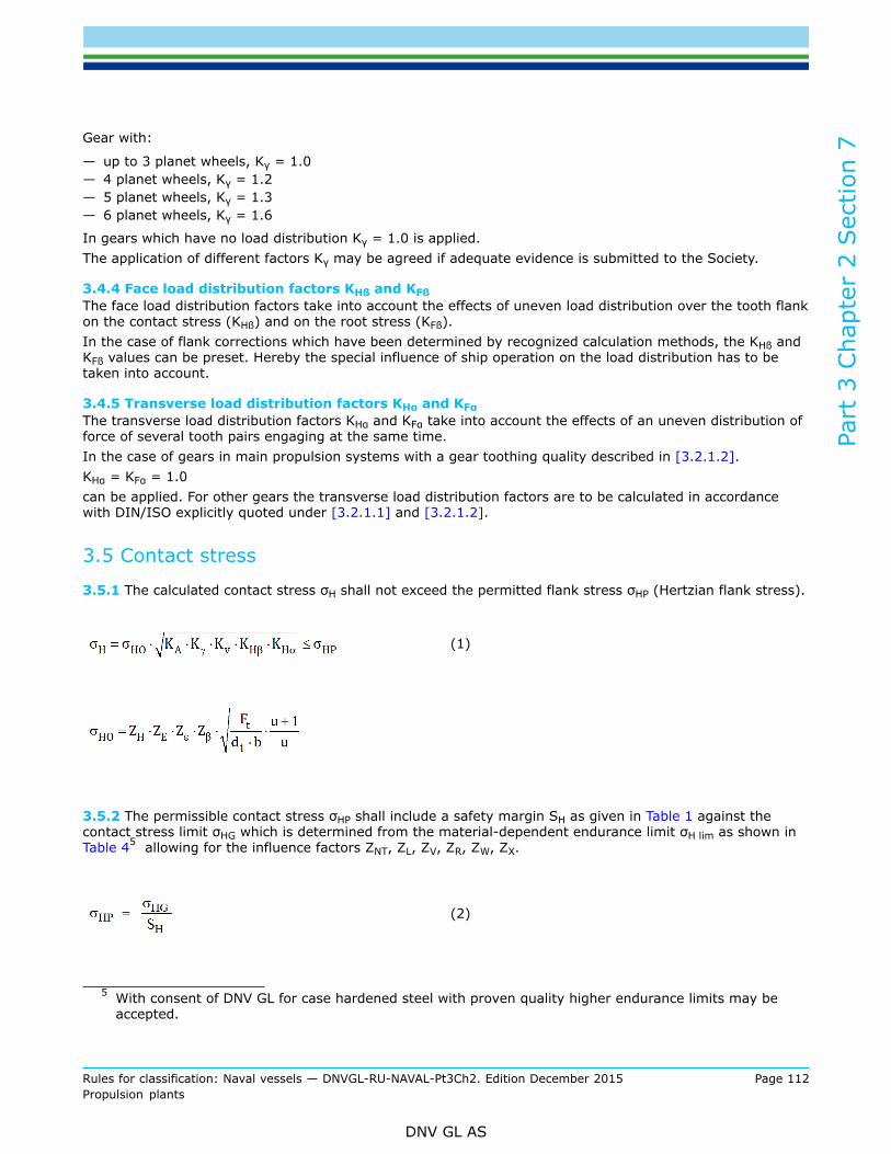
Part
3 C
hapt
er 2
Sec
tion
7
Rules for classification: Naval vessels — DNVGL-RU-NAVAL-Pt3Ch2. Edition December 2015 Page 112Propulsion plants
DNV GL AS
Gear with:
— up to 3 planet wheels, Kγ = 1.0— 4 planet wheels, Kγ = 1.2— 5 planet wheels, Kγ = 1.3— 6 planet wheels, Kγ = 1.6
In gears which have no load distribution Kγ = 1.0 is applied.The application of different factors Kγ may be agreed if adequate evidence is submitted to the Society.
3.4.4 Face load distribution factors KHß and KFßThe face load distribution factors take into account the effects of uneven load distribution over the tooth flankon the contact stress (KHß) and on the root stress (KFß).In the case of flank corrections which have been determined by recognized calculation methods, the KHß andKFß values can be preset. Hereby the special influence of ship operation on the load distribution has to betaken into account.
3.4.5 Transverse load distribution factors KHα and KFαThe transverse load distribution factors KHα and KFα take into account the effects of an uneven distribution offorce of several tooth pairs engaging at the same time.In the case of gears in main propulsion systems with a gear toothing quality described in [3.2.1.2].KHα = KFα = 1.0can be applied. For other gears the transverse load distribution factors are to be calculated in accordancewith DIN/ISO explicitly quoted under [3.2.1.1] and [3.2.1.2].
3.5 Contact stress
3.5.1 The calculated contact stress σH shall not exceed the permitted flank stress σHP (Hertzian flank stress).
(1)
3.5.2 The permissible contact stress σHP shall include a safety margin SH as given in Table 1 against thecontact stress limit σHG which is determined from the material-dependent endurance limit σH lim as shown inTable 45 allowing for the influence factors ZNT, ZL, ZV, ZR, ZW, ZX.
(2)
5 With consent of DNV GL for case hardened steel with proven quality higher endurance limits may beaccepted.
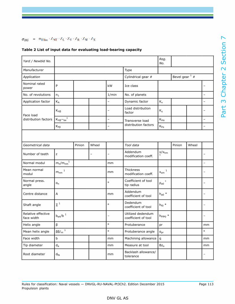
Part
3 C
hapt
er 2
Sec
tion
7
Rules for classification: Naval vessels — DNVGL-RU-NAVAL-Pt3Ch2. Edition December 2015 Page 113Propulsion plants
DNV GL AS
σHG =
Table 2 List of input data for evaluating load-bearing capacity
Yard / Newbld No. Reg.No.
Manufacturer Type
Application Cylindrical gear # Bevel gear 1 #
Nominal ratedpower P kW Ice class –
No. of revolutions n1 1/min No. of planets –
Application factor KA – Dynamic factor Kv –
KHβ – Load distributionfactor Kγ –
KHβ−be1 – KHα –
Face loaddistribution factors
KFβ –
Transverse loaddistribution factors KFα –
Geometrical data Pinion Wheel Tool data Pinion Wheel
Number of teeth z – – Addendummodification coeff.
x/xhm1 –
Normal modul mn/mnm1 mm –
Mean normalmodul mnm 1 mm Thickness
modification coeff. xsm 1 –
Normal press.angle αn ° Coefficient of tool
tip radius ρa0 * –
Centre distance A mm Addendumcoefficient of tool ha0 * –
Shaft angle ∑ 1 ° Dedendumcoefficient of tool hf0 * –
Relative effectiveface width beh/b 1 – Utilized dedendum
coefficient of tool hFfP0 * –
Helix angle β ° Protuberance pr mm
Mean helix angle ββ/m 1 ° Protuberance angle αpr °
Face width b mm Machining allowance q mm
Tip diameter da mm Measure at tool Bzo mm
Root diameter dfe mm Backlash allowance/tolerance –

Part
3 C
hapt
er 2
Sec
tion
7
Rules for classification: Naval vessels — DNVGL-RU-NAVAL-Pt3Ch2. Edition December 2015 Page 114Propulsion plants
DNV GL AS
Yard / Newbld No. Reg.No.
Lubrication data Quality
kin. viscosity 40°C ν40 mm2/s Quality acc. to DIN Q –
kin. viscosity 100°C ν100 mm2/s Mean peak to valleyroughness of flank RzH μm
Oil temperature ϑOil °C Mean peak to valleyroughness of root RzF μm
FZG load stage – Initial equivalentmisalignment Fβx μm
Material data Normal pitch error fpe μm
Material type Profile form error ff μm
Endurance limit forcontact stress σH lim N/mm2
Endurance limit forbending stress σF lim N/mm2
Surface hardness HV
Core hardness HV
Heat treatmentmethod –
Date:
Signature:
1) declaration for bevel gear
Table 3 Application factors
System type KA
Main system:
Turbines and electric drive systems 1.1
Diesel engine drive systems with fluid clutch between engine and gears 1.1
Diesel engine drive systems with highly flexible coupling between engine andgears 1.3
Diesel engine drive systems with no flexible coupling between engine andgears 1.5
Generator drives 1.5
Auxiliary system:

Part
3 C
hapt
er 2
Sec
tion
7
Rules for classification: Naval vessels — DNVGL-RU-NAVAL-Pt3Ch2. Edition December 2015 Page 115Propulsion plants
DNV GL AS
System type KA
Thruster with electric drive 1.1 (20 000 h) 1
Thruster drives with diesel engines 1.3 (20 000 h) 1
0.6 (300 h) 1Windlasses
2.0 (20 h) 1
0.6 (1000 h) 1Combined anchor and mooring winches
2.0 (20 h) 2
Note
1) Assumed operating hours2) Assumed maximum load of windlasses
For other types of system KA is to be sti-pulated separately.
Table 4 Endurance limits for contact stress σH lim1
Material σH lim [N/mm2]
Case-hardening steels, case-hardened 1500
Nitriding steels, gas nitrided 1250
Alloyed heat treatable steels, bath or gas nitrided 850 – 1000
Alloyed heat treatable steels, induction hardened 0.7 HV10 + 800
Alloyed heat treatable steel 1.3 HV10 + 350
Unalloyed heat treatable steel 0.9 HV10 + 370
Structural steel 1.0 HB + 200
Cast steel, cast iron and nodular cast graphite 1.0 HB + 150
1) With consent of DNV GL for case hardened steel with or over proven quality application of higher values for fatiguestrength may be accepted.
Table 5 Endurance limits for tooth root bending stress σFE = σF lim ∙ YST with YST = 2
Material σFE = σF lim* ∙ YST [N/mm2]
Case-hardened steels, case-hardened 860 – 920
Nitriding steels, gas nitrided 850
Alloyed heat treatable steel, bath or gas nitrided 740
Alloyed heat treatable steel, induction hardened 700
Alloyed heat treatable steels 0.8 HV10 + 400
Unalloyed heat treatable steel 0.6 HV10 + 320
Structural steel 0.8 HB + 180
Cast steel, cast iron with nodular graphite 0.8 HB + 140

Part
3 C
hapt
er 2
Sec
tion
7
Rules for classification: Naval vessels — DNVGL-RU-NAVAL-Pt3Ch2. Edition December 2015 Page 116Propulsion plants
DNV GL AS
Material σFE = σF lim* ∙ YST [N/mm2]
NoteFor alternating stressed toothing only 70% of these values are permissible.
With consent of DNV GL for case hardened steel with or over proven quality application of higher values for fatiguestrength may be accepted.
3.6 Tooth root bending stress
3.6.1 The calculated maximum root bending stress σF of the teeth shall not exceed the permissible rootstress σFP of the teeth.
The tooth root stress is to be calculated separately for pinion and wheel.
σF = σF0 ∙ KA ∙ Kv ∙ Kγ ∙ KFβ ∙ KFα ≤ σFP (3)
σF0 =
3.6.2 The permissible root bending stress σFP shall have a safety margin SF as indicated in Table 1 againstthe root stress limit σFG which is determined from the material-dependent fatigue strength σFE or σF lim inaccordance with Table 5 12, allowing for the stress correction factors YST, YNT, Yδ rel T, YR rel T, YX.
(4)
σFG =
4 Gear shafts
4.1 Minimum diameterThe dimensions of shafts of reversing and reduction gears are to be calculated by applying the followingformula:
For the expression

Part
3 C
hapt
er 2
Sec
tion
7
Rules for classification: Naval vessels — DNVGL-RU-NAVAL-Pt3Ch2. Edition December 2015 Page 117Propulsion plants
DNV GL AS
may be set to 1.0
d = required outside diameter of shaft [mm]di = diameter of shaft bore for hollow shafts [mm]da = actual shaft diameter [mm]P = driving power of shaft [kW]n = shaft speed [min-1]F = factor for the type of drive [–]
= 95 for turbine plants, electrical drives and engines with slip couplings= 100 for all other types of drive. The Society reserves the right to specify higher F values if this
appears necessary in view of the loading of the plant.Cw = material factor
=
Rm = tensile strength of the shaft material.For wheel shafts no higher value than 800 N/mm2 shall be used. For pinion shafts the actual tensilestrength may generally be substituted for Rm.
k = 1.10 in general= 1.15 in the area of the pinion or wheel body if this is keyed to the shaft and for multiple-spline
shaftsHigher values of k may be specified by the Society where increased bending stresses in the shaftare expected because of the bearing arrangement, the casing design, the tooth pressure, etc.
5 Equipment
5.1 Gear lubrication5.1.1 GeneralThe gear system has to be designed to enable a start with a lubrication oil temperature from 0°C upwardswithout restrictions.For engageable couplings the guidelines according to [7.5] are valid.Suitable equipment has to be provided, which limits the water content in the gear lubricant and the humiditywithin the gear in a way to exclude corrosion in the gear.
5.1.2 Oil level indicatorFor monitoring the lubricating oil level in main and auxiliary gears, equipment is to be fitted to enable the oillevel to be determined.
5.1.3 Pressure and temperature controlTemperature and pressure gauges are to be fitted to monitor the lubricating oil pressure and the lubricatingoil temperature at the oil-cooler outlet before it enters the gears.Plain journal bearings are also to be fitted with temperature indicators.Where gears are fitted with anti-friction bearings, a temperature indicator is to be mounted at a suitablepoint. For gears rated up to 2 000 kW, special arrangements may be agreed with the Society.

Part
3 C
hapt
er 2
Sec
tion
7
Rules for classification: Naval vessels — DNVGL-RU-NAVAL-Pt3Ch2. Edition December 2015 Page 118Propulsion plants
DNV GL AS
Where ships are equipped with automated machinery, the requirements of the DNV GL rules for AutomationCh.4 are to be complied with.
5.1.4 Lubricating oil pumpsLubricating oil pumps driven by the gearing are to be mounted in such a way that they are accessible andcan be replaced easily by using common board available tools.The supply of lubricating oil has to be ensured by a main pump and an independent stand by pump. If areduction gear is approved for sufficient self lubrication at 75% of the driving torque, the stand by pump maybe abolished up to a performance relation P/n1 [kW/min-1] ≤ 3.0.For the pumps to be assigned see Ch.5 Sec.8 [9.3].
5.2 Equipment for operation, control and safetyEquipment for operation and control has to enable a safe operation of the gear by remote control as well asdirectly at the gear. All parameters which are important for a regular operation are to be indicated directly atthe gear. These indicating instruments shall be put together in an auxiliary control stand, as far as possible.
5.3 Gear casingsThe casings of gears belonging to the main propulsion plant and to essential auxiliaries are to be fittedwith removable inspection covers to enable the toothing to be inspected, the thrust bearing clearance to bemeasured and the oil sump to be cleaned.
5.4 Seating of gearsIt has to be taken care that no inadmissible forces caused by deformation of the foundation as part of thehull structure are transferred to the toothing.The seating of gears on steel or cast resin chocks is to conform to DNVGL-CP-0144.For the seating of gears on casting resin chocks the thrust has to be absorbed by means of stoppers. Thesame applies for casting resin foundations of separate thrust bearings.
6 Balancing and testing
6.1 Balancing quality
6.1.1 Gear wheels, pinions, shafts, couplings and, where applicable, high-speed flexible couplings are to beassembled in a properly balanced condition.
6.1.2 The generally permissible residual imbalance U per balancing plane of gears for which static ordynamic balancing is rendered necessary by the method of manufacture and by the operating and loadingconditions can be determined by applying the formula
(6)
G = mass of component to be balanced [kg]n = operating speed of component to be balanced [min-1]z = number of balancing planes [–]

Part
3 C
hapt
er 2
Sec
tion
7
Rules for classification: Naval vessels — DNVGL-RU-NAVAL-Pt3Ch2. Edition December 2015 Page 119Propulsion plants
DNV GL AS
Q = degree of balance [–]
— 6.3 for gear shafts, pinion and coupling members for engine gears— 2.5 for torsion shafts and gear couplings, pinions and gear wheels belonging to turbine
transmissions
6.2 Testing6.2.1 Testing in the manufacturer's worksWhen the testing of materials and component tests have been carried out, gearing systems for the mainpropulsion plant and for essential auxiliaries in accordance with Sec.1 [2.4] are to be presented to theSociety for final inspection and operational testing in the manufacturer's works. For the inspection of weldedgear casings, see the DNV GL rules for Welding in the Various Fields of Application RU SHIP Pt.2.The final inspection is to be combined with a trial run lasting several hours under part or full-load conditions,on which occasion the tooth clearance and contact pattern are to be checked. In the case of a trial at full-load, any necessary running-in of the gears must have been completed beforehand. Where no test facilitiesare available for the operational and on-load testing of large gear trains, these tests may also be performedon board ship on the occasion of the dock trials.Tightness tests are to be performed on those components to which such testing is appropriate.Reductions in the scope of the tests require the consent of the Society.
6.2.2 Tests during sea trials
6.2.2.1 Prior to the start of sea trials, the teeth of the gears belonging to the main propulsion plant are tobe coloured with suitable dye to enable the check of the contact pattern. During the sea trials, the gears areto be checked at all forward and reverse speeds to establish their operational efficiency and smooth runningas well as the bearing temperatures and the pureness of the lubricating oil. At the latest on conclusion ofthe sea trials, the gearing is to be examined via the inspection openings and the contact pattern checked.If possible the contact pattern should be checked after conclusion of every load step. Assessment of thecontact pattern is to be based on the guide values for the proportional area of contact in the axial and radialdirections of the teeth given in Table 6 and shall take account of the running time and loading of the gearsduring the sea trial.
6.2.2.2 In the case of multistage gear trains and planetary gears manufactured to a proven high degree ofaccuracy and if an appropriate check at the manufacturer’s workshop was successful, checking of the contactpattern after sea trials may, with the consent of the Society, be reduced in scope.
6.2.2.3 For checking of gears of Z-drives, e.g. rudder propellers and azimuth propulsors, as main propulsionsee Sec.9 [4.8].
6.2.2.4
Table 6 Percentage area of contact
Material, manufacturing of toothing Working tooth depth (without tip relief) Width of tooth(without end relief)
heat-treated,milled,
shaped33% average 70%
surface-hardened,grinded,
scarped40% average 80%

Part
3 C
hapt
er 2
Sec
tion
7
Rules for classification: Naval vessels — DNVGL-RU-NAVAL-Pt3Ch2. Edition December 2015 Page 120Propulsion plants
DNV GL AS
6.2.3 Acoustic properties to be proven in compliance with the DNV GL rules for Hull Structures and ShipEquipment Ch.1 Sec.16 [2.3].
7 Design and construction of couplings
7.1 It shall be possible to disengage respectively to install and dismantle all couplings outside of gears using thetooling on board without displacing of major system's components such as gear, thrust bearing, engine, etc.
7.2 Flange and clamp-type couplingsIn the dimensional design of the coupling bodies, flanges and bolts of flange and clamp-type couplings, therules specified in Sec.6 are to be complied with.
7.3 Tooth couplings
7.3.1 Torsionally stiff couplings, such as multi-tooth couplings may be used to compensate deviations inradial and axial direction.
7.3.2 Adequate loading capacity of the tooth flanks of straight-flanked tooth couplings requires that thefollowing conditions are satisfied:
(7)
p = actual contact pressure of the tooth flanks [N/mm2]P = driving power at coupling [kW]d = standard pitch diameter [mm]KA = application factor in accordance with [3.4.2] [–]h = working depth of toothing [mm]b = load-bearing tooth width [mm]z = number of teeth [–]n = speed in rev/min [min–1]pzul = 0.7 . ReH for ductile steels [N/mm2]pzul = 0.7 . Rm for brittle steels [N/mm2]σHP = permissible Hertzian stress [N/mm2]
Where methods of calculation recognized by the Society are used for determining the Hertzian stress on theflanks of tooth couplings with convex tooth flanks, the permissible Hertzian stresses are equal to 75% of thevalues of σHP shown in [3.5.2] with influence factors ZNT to ZX set to 1.0:
pzul = 400 – 600 N/mm2 for tooth systems of quenched and tempered steel; the higher values apply tohigh tensile steels with superior tooth manufacturing and surface finish quality
= 800 – 1000 N/mm2 for toothing made of hardened steel (case or nitrogen). Higher values apply forsuperior tooth manufacturing and surface finish quality

Part
3 C
hapt
er 2
Sec
tion
7
Rules for classification: Naval vessels — DNVGL-RU-NAVAL-Pt3Ch2. Edition December 2015 Page 121Propulsion plants
DNV GL AS
7.3.3 The coupling teeth are to be effectively lubricated. For this purpose a permanent oil or greaselubrication in the coupling may generally be regarded as adequate where
[mm/min2] (8)For higher values of dn2, couplings in main propulsion plants are to be provided with a circulating lubricationoil system.
7.3.4 For the dimensional design of the sleeves, flanges and bolts of gear couplings the formulae given inSec.6 are to be applied.
7.4 Flexible couplings7.4.1 ScopeFlexible couplings shall be approved for the loads specified by the manufacturer and for use in mainpropulsion plants and essential auxiliary machinery. In general flexible couplings shall be type-approved.Detailed requirements for type approvals of flexible couplings are defined in DNV GL-CP-0147.
7.4.2 DocumentationThe documentation to be submitted shall include:
— assembly drawings— detailed drawings including material characteristics— definition of main parameters
— rubber Shore hardness— nominal torque TKN— permissible torque TKmax1 for normal transient conditions like starts/stops, passing through
resonances, electrical or mechanical engagements, ice impacts, etc.— permissible torque TKmax2 for abnormal impact loads like short circuits, emergency stops, etc.— permissible vibratory torque ± TKW for continuous operation— permissible power loss PKV due to heat dissipation— permissible rotational speed nmax— dynamic torsional stiffness cTdyn, radial stiffness crdyn— relative damping ψ respectively damping characteristics— permissible axial, radial and angular displacement— permissible permanent twist
— design calculations
— test reports
7.4.3 TestsThe specifications mentioned in [7.4.2] are to be proven and documented by adequate measurements at testestablishments. The test requirements are included in DNV GL-CP-0147.For single approvals the scope of tests may be reduced by agreement with the Society.
7.4.4 Design
7.4.4.1 With regard to casings, flanges and bolts the requirements specified in Sec.6 [4] are to be compliedwith.
7.4.4.2 The flexible element of rubber couplings shall be so designed that the average shear stress in therubber/metal bonding surface relating to TKN does not exceed a value of 0.5 N/mm2.

Part
3 C
hapt
er 2
Sec
tion
7
Rules for classification: Naval vessels — DNVGL-RU-NAVAL-Pt3Ch2. Edition December 2015 Page 122Propulsion plants
DNV GL AS
7.4.4.3 For the shear stress within the rubber element due to TKN it is recommended not to exceed a valuesubjected to the Shore hardness according to Table 7.Higher values can be accepted if appropriate strengths of rubber materials have been documented by meansof relevant tests and calculations.
Table 7 Limits of shear stress
Shore hardness[ – ]
Limit of shear stress[N/mm2]
40 0.4
50 0.5
60 0.6
70 0.7
For special materials, e.g. silicon, corresponding limit values shall be derived by experiments andexperiences.
7.4.4.4 Flexible couplings in the main propulsion plant and in power-generating plants shall be sodimensioned that they are able to withstand for a reasonable time operation with any one engine cylinder outof service, see Sec.10 [3.4.2]. Additional dynamic loads for ships with ice class are to be taken into accountaccording to Section 9.
7.4.4.5 If a flexible coupling is so designed that it exerts an axial thrust on the coupled members of thedriving mechanism, provision shall be made for the absorption of this thrust.If torsional limit devices are applicable, the functionality shall be verified.
7.4.4.6 Flexible couplings for diesel generator sets shall be capable of absorbing impact moments due toelectrical short circuits up to a value of 6 times the nominal torque of the plant.
7.5 Clutches7.5.1 General
7.5.1.1 Definition and applicationClutches are couplings which can be engaged and disengaged mechanically, hydraulically or pneumatically.The following requirements apply for their use in shaft lines and as integrated part of gear boxes. Clutchesintended for trolling operation are subject to special consideration.
7.5.1.2 DocumentationFor all new types of clutches a complete documentation has to be submitted to the Society for approval intriplicate. This documentation has to include e.g.:
— assembly drawings— detail drawings of torque transmitting components including material properties— documentation of the related system for engaging/disengaging— definition of the following main technical parameters
— maximum and minimum working pressure for hydraulic or pneumatic systems [bar]— static and dynamic friction torque [kNm]— time diagram for clutching procedure— operating manual with definition of the permissible switching frequency
Part
3 C
hapt
er 2
Sec
tion
7
Rules for classification: Naval vessels — DNVGL-RU-NAVAL-Pt3Ch2. Edition December 2015 Page 123Propulsion plants
DNV GL AS
— for special cases calculation of heat balance, if requested by the Society
7.5.2 MaterialsThe mechanical characteristics of materials used for the elements of the clutch shall conform to RU SHIP Pt.2.
7.5.3 Design requirements
7.5.3.1 Safety factorsFor the connections to the shafts on both sides of the clutch and all torque transmitting parts therequirements of Sec.6 have to be considered.The mechanical part of the clutch may be of multiple disc type. The multiple disc package shall be kept freeof external axial forces. All components shall be designed for static loads with a friction safety factor between1.8 and 2.5 in relation to the nominal torque of the driving plant.A dynamic switchable torque during engaging of 1.3 times the nominal torque of the driving plant hasgenerally to be considered. In case of combined multiple engine plants the actual torque requirements will bespecially considered.
7.5.3.2 Ice classFor clutches used for the propulsion of ships with ice class the reinforcements according to Sec.11 have to beconsidered.
7.5.3.3 Measures for a controlled switching of the coupling and an adequate cooling in all working conditionshave to be provided.
7.5.3.4 Auxiliary systems for engaging/ disengagingIf hydraulic or pneumatic systems are used to engage/ disengage a clutch within the propulsion systemof a ship with a single propulsion plant an emergency operation shall be possible. This may be done bya redundant power system for engagement/ disengagement or in a mechanical way, e.g. by installingconnecting bolts. For built-in clutches this would mean that normally the connecting bolts shall be installedon the side of the driving plant equipped with turning facilities.The procedure to establish emergency service has to be described in the operating manual of the clutch andhas to be executed in a reasonable time.
7.5.3.5 Controls and alarmsLocal operation of remotely controlled clutches for the propulsion plants shall be possible.The pressure of the clutch activating medium has to be indicated locally. Alarms according to the DNV GLrules for Automation Ch.4 Sec.9 [5] have to be provided.
7.5.4 Tests
7.5.4.1 Tests at the manufacturer’s worksMagnetic particle or dye penetrant inspection shall be applied for crack detection at surface hardened zoneswith increased stress level as well as at shrinkage surfaces. The manufacturer shall issue a ManufacturerInspection Certificate.Clutches for ship propulsion plants, for generator sets and transverse thrusters are to be presented to theSociety for final inspection and, where appropriate, for the performance of functional and tightness tests.If a type approval is requested the requirements will be defined on a case by case basis by the Society.
7.5.4.2 Tests on boardAs part of the sea trials the installed clutches will be tested for correct functioning on board in presence of asurveyor.

Part
3 C
hapt
er 2
Sec
tion
7
Rules for classification: Naval vessels — DNVGL-RU-NAVAL-Pt3Ch2. Edition December 2015 Page 124Propulsion plants
DNV GL AS
7.6 Hydraulic couplings/torque convertersThe torque characteristic of the hydraulic coupling has to be adjusted to the operating conditions. Ashydraulic oil the lubricating oil required for the diesel engines or the gears shall be used.A timely unlimited operation of the drive machines with empty coupling is to be guaranteed for the wholespeed range. The actual operation condition has to be indicated (for this see also Sec.2).
7.7 Mechanical clutches for multi-engine synchronization7.7.1 Basic descriptionFor propulsion plants driven by multiple power sources of different type (such as diesel engines and turbines)generally a switching over to alternative operational modes without intermediate shut-down or reduction ofthe speed of the driving engine may be required. For such purposes a synchronisation of the speed of theengines in duty and the idling engine should take place before introduction of mechanical clutch in procedure.The synchronisation aims to minimise the clutch in shock and induced peak torques, but also to enable anundisturbed and smooth continuous operation while changing the operational mode. The speed differencebefore introduction of clutch in procedure should not be more than 10 %, or depending on the moment ofinertias of the driving and driven parts the transient speed drop or increase after clutch in should be less than5%.
7.7.2 Design requirementsThe mechanical part of the clutch may be of multiple disc or mechanical teeth type. All components shallbe designed for the nominal transmitted torque with a safety factor of 2.5. In case that the speed is notsynchronised in accordance to [7.7.1] a safety factor of 3.5 must be reckoned with. In case that multipledisc plates or other frictional devices are applied, they should be set in a way that the slip point is reachedfor torque values between 150% and 250 % of the nominal torque, depending on the requirements of themanufacturer.Additional functions, like lock-in/lock-out control or position indication may be required depending on theoverall design of the propulsion plant.
7.8 TestingCouplings for ship propulsion plants and couplings for generator sets and transverse thrusters are to bepresented to the Society for final inspection and, where appropriate, for the performance of functional andtightness tests.

Part
3 C
hapt
er 2
Sec
tion
8
Rules for classification: Naval vessels — DNVGL-RU-NAVAL-Pt3Ch2. Edition December 2015 Page 125Propulsion plants
DNV GL AS
SECTION 8 PROPULSORS
1 General
1.1 ScopeThese rules apply to screw propellers (controllable and fixed pitch) as well as miscellaneous propulsionsystems. See Sec.11 for information on propeller sizes and materials for ships navigating in ice.
1.2 Documents for approval
1.2.1 Design drawings of propellers in main propulsion systems having an engine output in excess of 300 kWand in transverse thrust systems of over 500 kW, are to be submitted to the Society for approval. Thedrawings are required to contain all the details necessary to carry out an examination in accordance withthe following requirements. To facilitate a smooth and efficient approval process they should be submittedelectronically via MY DNV GL. In specific cases and following prior agreement with the Society they can alsobe submitted in paper form in triplicate.
1.2.2 In the case of controllable pitch propeller systems, general and sectional drawings of the completecontrollable pitch propeller system are to be submitted in addition to the design drawings for blade, boss andpitch control mechanisms. Control and hydraulic diagrams are to be submitted. In the case of new designs orcontrollable pitch propeller systems which are being installed for the first time on a ship with DNV GL class, adescription of the controllable pitch propeller system has also to be submitted.
1.3 Design
1.3.1 Propellers are to be designed in a way that their power consumption lies within the family ofcharacteristics of the driving machinery.
— The propeller of controllable pitch plants shall absorb the continuous rating of the driving machinery atnominal speed.
— A fixed pitch propeller shall reach the absorbed power/speed relation defined in the building specification.
1.3.2 For determination of the propeller parameters well known and established methods may be used. Thelay out of the propeller has to consider the noise requirements in the building specification, e.g. minimumcircumferential speed, etc. Nominal speed ahead and propeller diameter are to be selected for a maximumship speed without cavitation. The limit curve for cavitation noise in the SIGMAn - CTh diagram in [10] may beused. The noise emission from the propeller shall be estimated already in the concept phase.
1.3.3 Noise behaviour
1.3.3.1 Cavitation noiseThe propeller has to be designed to develop low noise, especially at the nominal acoustic operation point.Cavitation noise has to be avoided.
Guidance note:Guiding values for cavitation avoidance are contained in [10].
---e-n-d---of---g-u-i-d-a-n-c-e---n-o-t-e---
1.3.3.2 Singing behaviourBy calculating the natural frequencies of the propeller and by a comparison with the hydrodynamic excitationat the trailing edges the risk of singing of the propeller has to be estimated and minimised. If singing isobserved during trials, relevant counter measures have to be applied.
Part
3 C
hapt
er 2
Sec
tion
8
Rules for classification: Naval vessels — DNVGL-RU-NAVAL-Pt3Ch2. Edition December 2015 Page 126Propulsion plants
DNV GL AS
Guidance note:The singing of a propeller is a strong peak tone in the noise spectrum. It is created by the excitation of natural frequencies as aconsequence of vortex shedding at the trailing edge.
---e-n-d---of---g-u-i-d-a-n-c-e---n-o-t-e---
1.3.3.3 Air blow-out device1.3.3.3.1 Blow-out devices for air may be considered for naval ships for which low-noise operation isrequired in velocity ranges with cavitating propeller. If an air blow-out device is required in the buildingspecification, the system has to be agreed with the naval administration and the Society. The details of thedesign have to be included in the building specification.1.3.3.3.2 The exits of the blown-out air have to be arranged in a way that a compact air veil covers theblade surface. The feed of the air into the propulsion system should be done at the front end of the propellershaft. The air temperature at the shaft entrance should not be higher than 40°C. By special measures in theconstruction it has to be secured that no air penetrates into the hydraulic system. On the other hand no oil orwater shall get into the air system.1.3.3.3.3 For the creation of an effective air veil at the propeller blade the required air volume is dependingon the propeller speed. Therefore speed regulated air compressors have to be provided.1.3.3.3.4 All components and pipes of the air system have to be made of stainless steel.1.3.3.3.5 For ships with NBC protection the air should be sucked from outside of the citadel. Ventilation anddrainage pipes shall be conducted in closed form to the outside.
1.3.3.4 Measurements of water-borne noise1.3.3.4.1 The measurements of water-borne noise have to be executed in deep and shallow water accordingto the building specification.1.3.3.4.2 For the assessment of cavitation noise the following test criteria will be applied simultaneously:
— recording audible noise in the frequency range 30 Hz – 20 kHz— comparative evaluation of the relevant third filter analyses. Checking if a clear increase of noise level in
the complete frequency range above 1 kHz is to be observed or if with increased speed a transfer of thenoise peak to the range of 100 Hz is happening
— creation of a DEMON ("Demolition of Envelop Modulation on Noise") spectrum— measurement of the target level with a linear antenna
1.3.3.4.3 The execution of the measurements and the documentation of results has to be coordinated withthe Society.
1.3.4 Corrosion protectionThe propeller has to be protected against electro-chemical corrosion according to RU SHIP Pt.4 Ch.5 Sec.1[2].
1.4 DesignationEach propeller and the essential components for torque transmission and for blade adjustment of controllablepitch propellers respectively have to be definitely marked with the appropriate steel-stamp. The markingshave to be executed by steel-stamp numbers with rounded edges to avoid notch effects.
2 Materials
2.1 Propellers and propeller hubsThe material for the propulsion device has to be selected according to the actual functional requirements.Special materials are not prescribed. Materials and their parameters may be taken from the DNV GL rules forMetallic Materials RU SHIP Pt.2 Ch.2.

Part
3 C
hapt
er 2
Sec
tion
8
Rules for classification: Naval vessels — DNVGL-RU-NAVAL-Pt3Ch2. Edition December 2015 Page 127Propulsion plants
DNV GL AS
Metallic propellers are to be made of sea-water-resistant copper cast alloys or steel cast alloys with aminimum tensile strength Rm of 440 N/mm2.For the purpose of the following design rules governing the thickness of the propeller blades, the requisiteresistance to seawater of a cast copper alloy or cast steel alloy is considered to be achieved if the alloy canwithstand a fatigue test under alternating bending stresses comprising 108 load cycles amounting to about20% of the minimum tensile strength and carried out in a 3% NaCl solution, and provided that the fatiguestrength under alternating bending stresses in natural seawater can be proven to be not less than about 65%of the values established in 3% NaCl solution. Sufficient fatigue strength under alternating bending stresseshas to be proven by a method recognized by the Society.
2.2 Components for controllable pitch and assembled fixed pitch propellersThe materials of the major components of the pitch control mechanism and also the blade and boss retainingbolts have to comply with the DNV GL rules for Metallic Materials RU SHIP Pt.2 Ch.2.The blade retaining bolts of assembled fixed pitch propellers or controllable pitch propellers are to be made ofseawater-resistant materials so far they are not protected against contact with seawater.
2.3 Material parametersThe material has to be documented according to the DNV GL rules for Materials for Propeller Fabrication RUSHIP Pt.2.If materials shall be used which are not corresponding to the DNV GL grades, the following parameters haveto be delivered to the Society:
— designation of the material (acronym)— chemical composition— tensile strength, yield stress and elongation of a material sample (serves especially for the identification of
the material)— impact energy, if required— bending fatigue strength in sea water spray fog (serves as limit value for the strength calculations)— density of material, modulus of elasticity, thermal expansion coefficient— magnetic characteristics, if applicable— information concerning repairing ability (weldability, heat treatment)— information concerning resistance against corrosion and erosion
2.4 Novel materialsWhere propeller materials with not sufficient experience for their reliability are applied, the suitability has tobe proven particularly to the Society.
2.5 Material testingThe material of propellers, propeller bosses and all essential components involved in the transmission oftorque and pitch setting is to be tested in accordance with the DNV GL rules for Metallic Materials RU SHIPPt.2 Ch.2. This also applies to components which are used to control the blades and also to propellers in mainpropulsion systems smaller than 300 kW power and transverse thrust systems of less than 500 kW power.

Part
3 C
hapt
er 2
Sec
tion
8
Rules for classification: Naval vessels — DNVGL-RU-NAVAL-Pt3Ch2. Edition December 2015 Page 128Propulsion plants
DNV GL AS
3 Design and dimensioning of propellersAlternative design methods which guarantee the same sufficient safety may be submitted to the Society forapproval.
3.1 Symbols and termsA = effective area of a shrink fit [mm2]AD = propeller plane area [m2]B = developed blade width of cylindrical sections at radii 0.25 R, 0.35 R and 0.6 R [mm] in an expanded
viewcA = coefficient for shrunk joints [–]
= 1.0 for geared diesel engine and turbine plants as well as for electric motor drives= 1.2 for direct diesel engine drives
CG = size factor in accordance with formula (2) [–]CDyn = dynamic factor in accordance with formula (3) [–]Cw = characteristic value for propeller material as shown in Table 1 corresponds to the minimum tensile
strength Rm of the propeller material where sufficient fatigue strength under alternating bendingstresses according to [2.1] is proven [-]
C = conicity of shaft ends [–]
=
Table 1 Characteristic values Cw
Material Description 1 Cw
Cu 1 Cast manganese brass 440
Cu 2 Cast manganese nickel brass 440
Cu 3 Cast nickel aluminium bronze 590
Cu 4 Cast manganese aluminium bronze 630
Fe 3 Martensitic cast chrome steel 13/1-6 660
Fe 4 Martensitic-austenitic cast steel 17/4 600
Fe 5 Ferritic-austenitic cast steel 24/8 600
Fe 6 Austenitic cast steel 17/8-11 500
1) for the chemical composition of the alloys, see DNV GL rules Ship – Part 2 – Materials and Welding
CTh = thrust load coefficient
=
d = pitch circle diameter of blade or propeller-fastening bolts [mm]di = diameter of shaft bore [mm]

Part
3 C
hapt
er 2
Sec
tion
8
Rules for classification: Naval vessels — DNVGL-RU-NAVAL-Pt3Ch2. Edition December 2015 Page 129Propulsion plants
DNV GL AS
dk = root diameter of blade or propeller-fastening bolts [mm]D = diameter of propeller [mm]
= 2 ∙ Rdm = mean taper diameter [mm]DN = mean outer diameter of propeller hub [mm]e = blade rake acc. Figure 1 [mm]
= R ∙ tan εEN = modulus of elasticity for hub material [N/mm2]EW = modulus of elasticity for shaft material [N/mm2]ET = thrust stimulating factor in accordance with formula (5) [–]f, f1, f2 = factors in formulae (2), (4) and (11) [–]H = pressure side pitch of propeller blade at radii 0.25 R, 0.35 R and 0.6 R [mm]Hm = mean effective pressure side pitch for pitch varying with the radius [mm]
=
= R, B and H are the corresponding measures of the various sectionsk = coefficient for various profile shapes in accordance with Table 2 [–]
Table 2 Values of k for examples of various profile shapes
Values of kProfile shape
0.25, R 0.35 R 0.6 R
73 62 44
Segmental profiles with circular arced suctionside
77 66 47
Segmental profiles with parabolic suction side
80 66 44
Blade profiles as for Wageningen B Seriespropellers
KN = diameter ratio of hub [–] = dm/DN
KW = diameter ratio of shaft [–] = di/dm
L = pull-up length of propeller on cone [mm]
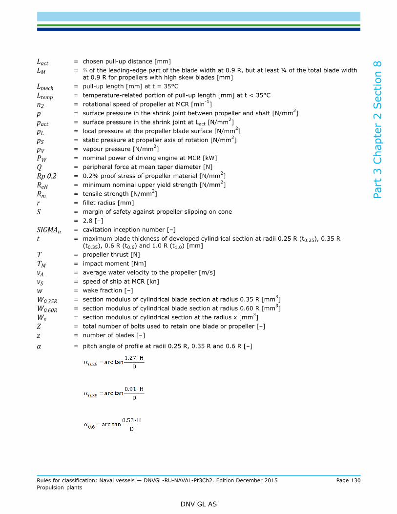
Part
3 C
hapt
er 2
Sec
tion
8
Rules for classification: Naval vessels — DNVGL-RU-NAVAL-Pt3Ch2. Edition December 2015 Page 130Propulsion plants
DNV GL AS
Lact = chosen pull-up distance [mm]LM = ⅔ of the leading-edge part of the blade width at 0.9 R, but at least ¼ of the total blade width
at 0.9 R for propellers with high skew blades [mm]Lmech = pull-up length [mm] at t = 35°CLtemp = temperature-related portion of pull-up length [mm] at t < 35°Cn2 = rotational speed of propeller at MCR [min-1]p = surface pressure in the shrink joint between propeller and shaft [N/mm2]pact = surface pressure in the shrink joint at Lact [N/mm2]pL = local pressure at the propeller blade surface [N/mm2]pS = static pressure at propeller axis of rotation [N/mm2]pV = vapour pressure [N/mm2]PW = nominal power of driving engine at MCR [kW]Q = peripheral force at mean taper diameter [N]Rp 0.2 = 0.2% proof stress of propeller material [N/mm2]ReH = minimum nominal upper yield strength [N/mm2]Rm = tensile strength [N/mm2]r = fillet radius [mm]S = margin of safety against propeller slipping on cone
= 2.8 [–]SIGMAn = cavitation inception number [–]t = maximum blade thickness of developed cylindrical section at radii 0.25 R (t0.25), 0.35 R
(t0.35), 0.6 R (t0.6) and 1.0 R (t1.0) [mm]T = propeller thrust [N]TM = impact moment [Nm]vA = average water velocity to the propeller [m/s]vS = speed of ship at MCR [kn]w = wake fraction [–]W0.35R = section modulus of cylindrical blade section at radius 0.35 R [mm3]W0.60R = section modulus of cylindrical blade section at radius 0.60 R [mm3]Wx = section modulus of cylindrical section at the radius x [mm3]Z = total number of bolts used to retain one blade or propeller [–]z = number of blades [–]
α = pitch angle of profile at radii 0.25 R, 0.35 R and 0.6 R [–]
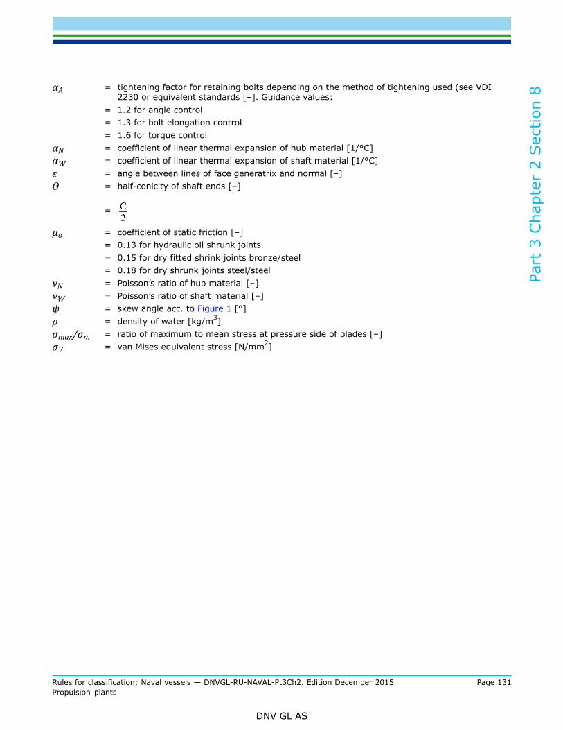
Part
3 C
hapt
er 2
Sec
tion
8
Rules for classification: Naval vessels — DNVGL-RU-NAVAL-Pt3Ch2. Edition December 2015 Page 131Propulsion plants
DNV GL AS
αA = tightening factor for retaining bolts depending on the method of tightening used (see VDI2230 or equivalent standards [–]. Guidance values:
= 1.2 for angle control= 1.3 for bolt elongation control= 1.6 for torque control
αN = coefficient of linear thermal expansion of hub material [1/°C]αW = coefficient of linear thermal expansion of shaft material [1/°C]ε = angle between lines of face generatrix and normal [–]Θ = half-conicity of shaft ends [–]
=
µo = coefficient of static friction [–]= 0.13 for hydraulic oil shrunk joints= 0.15 for dry fitted shrink joints bronze/steel= 0.18 for dry shrunk joints steel/steel
νN = Poisson’s ratio of hub material [–]νW = Poisson’s ratio of shaft material [–]ψ = skew angle acc. to Figure 1 [°]ρ = density of water [kg/m3]σmax/σm = ratio of maximum to mean stress at pressure side of blades [–]σV = van Mises equivalent stress [N/mm2]

Part
3 C
hapt
er 2
Sec
tion
8
Rules for classification: Naval vessels — DNVGL-RU-NAVAL-Pt3Ch2. Edition December 2015 Page 132Propulsion plants
DNV GL AS
Figure 1 Illustration of blade geometry
3.2 Calculation of blade thickness
3.2.1 At radii 0.25 R (t0.25) and 0.6 R (t0.6), the blade thicknesses of solid propellers have at least to complywith the formula (1):
t = Ko ∙ k ∙ K1 ∙ CG ∙ CDyn (1)
Ko =
k = as in Table 2= k' for other profiles as defined in Table 2
k' =
βx = factor for the section modulus of the cylindrical section related to the pitch line of the blade forprofile shapes defined in Table 2

Part
3 C
hapt
er 2
Sec
tion
8
Rules for classification: Naval vessels — DNVGL-RU-NAVAL-Pt3Ch2. Edition December 2015 Page 133Propulsion plants
DNV GL AS
βx' = factor for the section modulus of the cylindrical section related to the pitch line of the blade forprofile shapes other than defined in Table 2
=
K1 =
CG = size factor [–]
=
(2)
f1 = 7.2 for solid propellers6.2 for separately casted blades of variable pitch or built-up propellers
CDyn = dynamic load factor [–]
= (3)
for , otherwise CDyn = 1.0
σmax/σm is generally to be taken from the detailed calculation according to [3.2.5]. If, in exceptional cases,no such calculation exists, the stress ratio may be calculated approximately according to formula (4).
= f2 ∙ ET + 1 with (4)
ET ≈ (5)
f2 = 0.4 − 0.6 for single-screw ships, the lower value applies to stern shapes with a big propeller tipclearance and no rudder heel, the larger value to sterns with small clearance and with rudder heel.Intermediate values are to be selected accordingly
= 0.2 for twin-screw ships
3.2.2 The blade thicknesses of controllable pitch propellers are to be determined at radii 0.35R and 0.6R byapplying formula (1).For ships other than tugs, trawlers, etc. the diameter/pitch ratio D/Hm applicable to open-water navigation atmaximum engine power (MCR = Maximum Continuous Rating) can be used in formula (1).
3.2.3 The blade thicknesses calculated by applying formula (1) represent the lowest acceptable values forthe finish-machined propellers.

Part
3 C
hapt
er 2
Sec
tion
8
Rules for classification: Naval vessels — DNVGL-RU-NAVAL-Pt3Ch2. Edition December 2015 Page 134Propulsion plants
DNV GL AS
3.2.4 The fillet radii at the transition from the pressure and suction side of the blades to the propeller bossshall correspond, in the case of three and four-bladed propellers, to about 3.5% of the propeller diameter.For propellers with a larger number of blades the maximum possible fillet radii allowed by the propellerdesign shall be aimed at, but these shall not be chosen less than 40 of the blade root thickness.Variable fillet radii which are aiming at a uniform stress distribution, may be applied if an adequate proof ofstress is given case by case. The resulting calculated maximum stress shall not exceed the values occurringfrom a design with constant fillet radius in accordance with the first paragraph of [3.2.4].
3.2.5 For special designs such as propellers with skew angle ψ ≥ 25°, tip fin propellers, special profiles, etc.a special mechanical strength calculation is to be submitted to the Society.For re-calculation of the blade stress of these special propeller designs a blade geometry data file and detailson the measured wake field are to be submitted to the Society, together with the design documentation. Thisfile should be sent in plain text format. Supplementary information on the Classification of special designscan be requested by the Society.
3.2.6 If the propeller is subjected to an essential wear, e.g. by abrasion in tidal flats or rivers, a wearaddition has to be provided to the thickness determined under [3.2.1] to achieve an equivalent life time. Ifthe actual thickness in service drops below 50% at the blade tip or 90% at other radii of the rule thicknessobtained from [3.2.1], effective counter measures have to be taken. For unconventional blade geometries asdefined in [3.2.5], the design thickness as shown on the approved drawings replaces the thickness requestedaccording to [3.2.1].
4 Controllable pitch propellers
4.1 GeneralFor multi-shaft propulsion plants separated hydraulic systems have to be provided for each controllable pitchpropeller.
4.2 DesignFor the design of the components, the following aspects have to be considered.
4.2.1 The adjustment of the controllable pitch propeller has to be done in a way that at a position "zero"of the operating lever and minimum operation speed, zero thrust is developed. If deviations because ofadjustment tolerances are occurring, only thrust ahead shall be created.
Guidance note:The maximum adjustable pitch ahead should be at least 108% of the design pitch [mm], the maximum pitch astern should be atleast 70% of the design pitch [mm].
---e-n-d---of---g-u-i-d-a-n-c-e---n-o-t-e---
4.2.2 The construction of controllable pitch propeller plants has to be flood safe, if required in the buildingspecification.
4.2.3 The installation and the dismantling of the controllable pitch propellers shall be possible without axialdisplacement of the shafts. The leading edge of the blade shall lead without overhang to the blade root disc.
4.2.4 The hub shall be tightened reliably. The space before the blade gaskets shall stay under constantpressure to avoid pressure and volume variations at the gaskets during pitch variation. A device has to beprovided which allows flushing of the hub content at the floating ship. The blade position for this procedurehas to be marked at a flange of the propeller shaft in the hull with "P" (purging).

Part
3 C
hapt
er 2
Sec
tion
8
Rules for classification: Naval vessels — DNVGL-RU-NAVAL-Pt3Ch2. Edition December 2015 Page 135Propulsion plants
DNV GL AS
4.2.5 The following blade positions of each blade have to be marked permanently at the hub:
— maximum pitch ahead— design pitch— zero thrust position— maximum pitch ahead and astern
4.3 Emergency control
4.3.1 Controllable pitch propeller plants are to be equipped with means for emergency control to maintainthe function of the controllable pitch propeller in case of failure of the remote control system. It isrecommended to provide a device enabling the propeller blades to be locked in the “ahead” setting position.This pitch has to be selected in a way that a start of the propulsion system is possible with the weakestdriving machinery and at a standstill of the ship. Afterwards it shall be possible to operate the system like afixed pitch propeller.
4.3.2 Suitable devices have to prevent that an alteration of the blade pitch setting can lead to an overload orstall of the propulsion engine.It has to be ensured that, in the event of failure of the control system, the setting of the blades
— does not change, or— drifts to a final position slowly enough to allow the emergency control system to be put into operation
4.4 Hydraulic control equipment
4.4.1 Where the pitch-control mechanism is operated hydraulically, two mutually independent, power drivenpump sets are to be installed. For propulsion plants up to 200 kW, one power-driven pump set is sufficientprovided that, in addition, a hand-operated pump is provided, capable to control the blade pitch and beingable to move the blades from ahead to the astern position in a sufficiently short time for save manoeuvring.The selection and arrangement of filters has to ensure an uninterrupted supply with filtered oil, also duringfilter cleaning or exchange. In general, main filters are to be arranged on the pressure side directly afterthe pump. An additional coarse filtration of the hydraulic oil at the suction side, before the pump, should beprovided.For all operating conditions the adjusting time between design pitch and maximum astern pitch shall bedefined in building specification. Guidance values are:
— 22 s maximum for propellers with a diameter D ≤ 3.0 m— 30 s maximum for propellers with a diameter D > 3.0 m
4.4.2 The lay-out of the hydraulic system shall ensure that the electrically driven pumps are activated incase that:
— the mechanically driven pump fails— parallel operation with the mechanically driven pump in the lower speed range is required— short adjustment times are necessary, e.g. at manoeuvring operation
4.4.3 Each pump for the control oil has to be designed for a suitable angle velocity for blade adjustment. Aguide value is 2.5° per second. This velocity is valid for:
— operation with the electrically driven pump for the complete speed range— operation with the mechanically driven pump at nominal speed of the propeller
4.4.4 For hydraulic pipes and pumps in the DNV GL rules for Ship Operation Installations and AuxiliarySystems Ch.4 Sec.8 has to be applied.

Part
3 C
hapt
er 2
Sec
tion
8
Rules for classification: Naval vessels — DNVGL-RU-NAVAL-Pt3Ch2. Edition December 2015 Page 136Propulsion plants
DNV GL AS
4.5 Pitch control mechanismFor the pitch control mechanism proof is to be furnished that the individual components when subjected toimpact loads still have a safety factor of 1.5 against the yield strength of the materials used. The impactmoment TM has to be calculated according to formula (6) and the resulting equivalent stresses at thedifferent components are to be compared with their yield strength.
(6)
W0.6R can be calculated by applying the formula (7).
(7)
The components have to be designed fatigue-resistant for the maximum pressure.
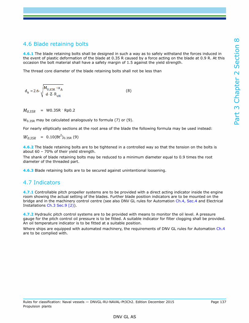
Part
3 C
hapt
er 2
Sec
tion
8
Rules for classification: Naval vessels — DNVGL-RU-NAVAL-Pt3Ch2. Edition December 2015 Page 137Propulsion plants
DNV GL AS
4.6 Blade retaining bolts
4.6.1 The blade retaining bolts shall be designed in such a way as to safely withstand the forces induced inthe event of plastic deformation of the blade at 0.35 R caused by a force acting on the blade at 0.9 R. At thisoccasion the bolt material shall have a safety margin of 1.5 against the yield strength.
The thread core diameter of the blade retaining bolts shall not be less than
(8)
M0.35R = W0.35R . Rp0.2
W0.35R may be calculated analogously to formula (7) or (9).
For nearly elliptically sections at the root area of the blade the following formula may be used instead:
W0.35R = 0.10(Bt2)0.35R (9)
4.6.2 The blade retaining bolts are to be tightened in a controlled way so that the tension on the bolts isabout 60 – 70% of their yield strength.The shank of blade retaining bolts may be reduced to a minimum diameter equal to 0.9 times the rootdiameter of the threaded part.
4.6.3 Blade retaining bolts are to be secured against unintentional loosening.
4.7 Indicators
4.7.1 Controllable pitch propeller systems are to be provided with a direct acting indicator inside the engineroom showing the actual setting of the blades. Further blade position indicators are to be mounted on thebridge and in the machinery control centre (see also DNV GL rules for Automation Ch.4, Sec.4 and ElectricalInstallations Ch.3 Sec.9 [2)).
4.7.2 Hydraulic pitch control systems are to be provided with means to monitor the oil level. A pressuregauge for the pitch control oil pressure is to be fitted. A suitable indicator for filter clogging shall be provided.An oil temperature indicator is to be fitted at a suitable position.Where ships are equipped with automated machinery, the requirements of DNV GL rules for Automation Ch.4are to be complied with.

Part
3 C
hapt
er 2
Sec
tion
8
Rules for classification: Naval vessels — DNVGL-RU-NAVAL-Pt3Ch2. Edition December 2015 Page 138Propulsion plants
DNV GL AS
5 Propeller mounting
5.1 Tapered mountings for fixed propellers
5.1.1 Where the cone connection between the shaft and the propeller is fitted with a key, the propeller isto be mounted on the tapered shaft in such a way that approximately 120 % of the mean torque can betransmitted from the shaft to the propeller by friction.Keyed connections are in general not to be used in installations with a barred speed range.
5.1.2 Where the connection between propeller shaft cone and propeller is realised by the hydraulic oiltechnique without the use of a key, the necessary pull-up distance L on the tapered shaft is to be determinedaccording to formula (10). Where appropriate, allowance is also to be made for surface smoothing whencalculating L.
L = Lmech + Ltemp (10)
where Lmech is determined according to the formulae of elasticity theory applied to shrunk joints for a specificpressure p [N/mm2] at the mean taper diameter found by applying formula (11) and for a water temperatureof 35°C .
(11)
T has to be introduced as positive value if the propeller thrust increases the surface pressure at the taper.Change of direction of propeller thrust is to be neglected as far as absorbed power and thrust are essentialless.
T has to be introduced as negative value if the propeller thrust reduces the surface pressure at the taper, e.g.for tractor propellers.
f = (11a)
Ltemp = (12)
t = temperature at which the propeller is mounted [°C]
Values for αN and αW can be taken from Table 3. At least the temperature range between 0°C and 35°C hasto be considered.
5.1.3 For keyless propeller fittings without intermediate sleeve, the required pull-up distance and relatedstresses in the propeller hub and shaft can be calculated as follows.
Joint stiffness factor:

Part
3 C
hapt
er 2
Sec
tion
8
Rules for classification: Naval vessels — DNVGL-RU-NAVAL-Pt3Ch2. Edition December 2015 Page 139Propulsion plants
DNV GL AS
Values for EN, EW, νN and νW can be taken from Table 3.
Minimum required pull-up distance at mounting temperature 35°C:
Lmech = p ∙ Kel
Minimum required pull-up distance at mounting temperature t [°C]:
L = Lmech + Ltemp
Surface pressure at the mean taper diameter at chosen pull-up distance Lact [mm]:
pact = Lact / Kel
Related van Mises’ equivalent stresses:
σV = (hub)
σV = pact (solid shaft)σV = pact ∙ 2 / (1 – KW
2) (hollow shaft)
Table 3 Material values
Material Modulus of elasticityE [N/mm²] Poisson’s ratio ν[-] Coefficient of linear
thermal expansion α [1/°C]
Steel 205000 0.29 12.0 . 10-6
Copper based alloys CU1and CU2 105000 0.33 17.5 . 10-6
Copper based alloys CU3and CU4 115000 0.33 17.5 . 10-6
NoteFor austenitic stainless steel see manufacturer’s specification
5.1.4 The van Mises' equivalent stress resulting from the maximum surface pressure p and the tangentialstress in the bore of the propeller hub shall not exceed 75 % of the 0.2 % proof stress or yield strength ofthe propeller material in the installed condition and 90 % during mounting and dismounting.
5.1.5 The cones of propellers which are mounted on the propeller shaft by means of the hydraulic oiltechnique should not be more than 1 : 15 and not be less than 1 : 25. For keyed connections the cone shallnot be steeper than 1:10.
5.1.6 The propeller nut shall be strongly secured to the propeller shaft.

Part
3 C
hapt
er 2
Sec
tion
8
Rules for classification: Naval vessels — DNVGL-RU-NAVAL-Pt3Ch2. Edition December 2015 Page 140Propulsion plants
DNV GL AS
5.2 Flange connections
5.2.1 Flanged propellers and the hubs of controllable pitch propellers are to be connected by means of fittedpins and retaining bolts (preferably necked down bolts).
5.2.2 The diameter of the fitted pins is to be calculated by applying formula (4) given in Sec.6 [4.4.3].
5.2.3 The propeller retaining bolts are to be designed according to [4.6], however the thread core diametershall not be less than
5.2.4 The propeller retaining bolts have to be secured against unintentional loosening.
6 Balancing and testing
6.1 BalancingMonobloc propellers ready for mounting as well as the blades of controllable and built up fixed pitchpropellers are required to undergo static balancing. Thereby the mass difference between blades ofcontrollable or built-up fixed pitch propellers has to be not more than 1.5%.
6.2 Testing
6.2.1 Fixed pitch propellers, controllable pitch propellers and controllable pitch propeller systems are to bepresented to the Society for final inspection and verification of the dimensions.The Society reserves the right to require non-destructive tests to be conducted to detect surface cracks orcasting defects.In addition, controllable pitch propeller systems shall undergo pressure, tightness and functional tests.
6.2.2 Casted propeller boss caps, which also serve as corrosion protection, have to be tested for tightness atthe manufacturer’s workshop. The Society reserves the right to require a tightness test of the aft propellerboss sealing in assembled condition.
6.2.3 If the propeller is mounted onto the shaft by a hydraulic shrink fit connection, a blue print test showingat least a 70 % contact area has to be demonstrated to the surveyor. The blue print pattern shall not showany larger areas of contact, especially not at the forward cone end. The proof has to be demonstrated usingthe original components.If alternatively a male/female calibre system is used, between the calibres a contact area of at least 80 % ofthe cone area has to be demonstrated and certified. After ten applications or five years the blue print proofhas to be renewed.
6.3 Quality classes of propellers
6.3.1 The requirements for the quality classes are given in the international standards ISO 484/1 and 484/2.

Part
3 C
hapt
er 2
Sec
tion
8
Rules for classification: Naval vessels — DNVGL-RU-NAVAL-Pt3Ch2. Edition December 2015 Page 141Propulsion plants
DNV GL AS
6.3.2 The quality of manufacturing and the accuracy of the dimensions of propellers shall be adequate totheir use.
7 Lateral thrust units
7.1 General7.1.1 ScopeThe requirements contained in 7 apply to the lateral thrust unit, the control station and all the transmissionelements from the control station to the lateral thrust unit.
7.1.2 Documents for approvalAssembly and sectional drawings for lateral thrust units with an input power of 100 kW and more togetherwith detail drawings of the gear mechanism and propeller containing all the data necessary for checkingare each to be submitted to the Society for approval. For propellers, this only applies to an input powerexceeding 500 kW.
7.2 MaterialsMaterials are subject, as appropriate, to the provisions of Sec.7 [2.7] applies analogously to the materialsand the material testing of propellers.
7.3 Dimensioning and design7.3.1 General requirementsThe dimensional design of the driving mechanisms of lateral thrust units is governed by Sec.6 and Sec.7,that of the propellers by [3].The pipe connections of hydraulic drive systems are subject to the applicable requirements contained inSec.9 [6].Lateral thrust units are to be capable of being operated independently of other connected systems.Windmilling of the propeller during sea passages has to be taken into account as an additional load case.Otherwise effective countermeasures have to be introduced to avoid windmilling, e.g. a shaft brake.In the propeller area, the thruster tunnel is to be protected against damages caused by cavitation erosion byeffective measures, such as stainless steel plating.For monitoring the lubricating oil level, equipment shall be fitted to enable the oil level to be determined.For the electrical equipment of lateral thrust units, see the DNV GL rules for Electrical Installations Ch.3 Sec.7[2].
7.3.2 Additional requirements for lateral thrust units for dynamic positioningBearings, sealings, lubrication, hydraulic system and all other aspects of the design are to be suitable forcontinuous, uninterrupted operation.Gears shall comply with the safety margins for DP as specified in Sec.7 Table 1. The lubrication system forthe gearbox shall comply with Sec.7 [5].For units with controllable pitch propellers, the hydraulic system has to comply with [4.7.2]. The selectionand arrangement of filters has to ensure an uninterrupted supply with filtered oil, also during filter cleaningand exchange.Where ships are equipped with automated machinery, the thruster unit has to comply with the requirementsfor main gears and main propellers in the DNV GL rules for Automation Ch.4.
Part
3 C
hapt
er 2
Sec
tion
8
Rules for classification: Naval vessels — DNVGL-RU-NAVAL-Pt3Ch2. Edition December 2015 Page 142Propulsion plants
DNV GL AS
7.4 Tests in the manufacturer's worksSec.9 [8] is applicable as appropriate.For hydraulic pumps and motors with a drive power of 100 kW or more, the tests are to be conducted in thepresence of a surveyor.For lateral thrust units with an input power of less than 100 kW final inspection and function tests may becarried out by the manufacturer, who will then issue the relevant Manufacturer Inspection Certificate.
7.5 Shipboard trialsTesting is to be carried out during sea trials during which the operating times are to be established.
7.6 Casting defectsPropellers shall be free of cracks. The correction of defects has to be executed for copper cast alloysaccording to the DNV GL rules for Materials for Propeller Fabrication Pt.2 and for stainless steel according toSec.2.
8 Special forms of propulsion systems
8.1 General
8.1.1 The investigation for a propulsion system most suitable for an actual naval ship should include specialforms of propulsion. Lay-out and arrangement of these propulsion systems have to be coordinated closelywith the manufacturer of the system.
8.1.2 Requirements for design and manufacturing have to be specified in the building specification.Concerning strength and model tests the rules for propellers have to be applied accordingly. Model tests haveto be performed in order to proof the reliability and check special performance characteristics.
8.1.3 In the following the design characteristics of several propulsion systems are defined. The scope doesnot fulfil the demand for entirety.
8.2 Cycloidal propellers
8.2.1 Cycloidal propellers are propulsion devices with blades rotating around a vertical axis and are able tochange the thrust in size and direction.
8.2.2 If low noise emission is required, the following principles should be observed:
— the size of the device with a minimum circumferential speed of the wheel body at the nominal acousticlay-out point has to be chosen
— an operation mode has to be used where the adjustment of the thrust is achieved by adjusting thenumber of revolutions
— the arrangement in the hull shall enable a distance to the sonar system which is as big as possible (sternarrangement)
— for the reduction of the intake speed a low-noise gear has to be provided— the connection of the housing to the ship foundation shall be established by an elastic mounting. The
foundation as part of the hull structure shall be of appropriate stiffness— the surface of the wheel body at the same level as the ship's bottom has to be coated with antidrumming
material

Part
3 C
hapt
er 2
Sec
tion
8
Rules for classification: Naval vessels — DNVGL-RU-NAVAL-Pt3Ch2. Edition December 2015 Page 143Propulsion plants
DNV GL AS
8.2.3 If a low magnetic signature is required, a high content of non-magnetizable materials has to beprovided, for reference see the DNV GL rules for Special Materials for Naval Ships Pt.2 Ch.5.
8.3 Supercavitating propellersThe blades of supercavitating propellers are to be designed to achieve a stable cavitation layer over thecomplete blade surface at the nominal lay-out point. Lay-out and design have to observe the foreseenoperation characteristics and the demanded reversing and steering ability.
8.4 Partially submerged propellersPartially submerged propellers are designed for an arrangement at the ship where the propeller blades breakthrough the water surface.Because of the high transverse forces this type of propulsion is only applicable for multi-shaft propulsionsystems. The degree of submerging has to be chosen to achieve a stable ventilation at the suction side.
8.5 Water jet propulsion system8.5.1 ScopeThese requirements apply to all devices producing a thrust by jet. This includes pump jets as well as waterjets and comparable drives.
8.5.2 Design
8.5.2.1 The lay-out data have to be coordinated with the manufacturer of the water jet propulsionaggregate. At all operating conditions no cavitation shall occur in the pump which can lead to damage ofthe components. To achieve this already in the design phase, the manufacturer has to indicate the areas oferosive cavitation danger.
8.5.2.2 Requirements for the manoeuvring abilities have to be specified in the building specification.
8.5.2.3 If it is not planned to equip all propulsion units of a multi-shaft ship with manoeuvring devices, ithas to be ensured in the building specification that all requirements concerning rudder effect, stopping time,survivability and redundancy are defined and can be met.
8.5.3 ArrangementPump shaft and entrance duct have to be arranged parallel to the longitudinal midship plane of the ship. Thepump shaft shall be parallel to the waterline in the trimmed condition of the ship. The pump is to be arrangedin a height that a quick start of the system is ensured for the minimum draught of the ship.
8.5.4 Construction requirements
8.5.4.1 The pump has to be integrated in the hull structure in a way that the maximum longitudinal andtransverse forces occurring during acceleration or crash-stop operation and during manoeuvres with the jet inthe maximum steering position are safely withstood.Detachable connections to the ship's hull shall enable an easy installation and dismounting of the pump unit.
8.5.4.2 The form of the entrance duct has to be coordinated with the manufacturer of the water jet unit. Thestream towards the pump has to be continuous and cavitation shall be avoided in the complete inlet area.The entrance duct has to be arranged to exclude the possibility of air ingress.
8.5.4.3 To protect the pump from flotsam a protection grid has to be arranged at a suitable location of theentrance duct. Before this grid an inspection port has to be provided. It shall be possible to open this port

Part
3 C
hapt
er 2
Sec
tion
8
Rules for classification: Naval vessels — DNVGL-RU-NAVAL-Pt3Ch2. Edition December 2015 Page 144Propulsion plants
DNV GL AS
and have access to it at floating ship. It shall be possible to clean the intake protection grid by reversing theflow direction.
8.5.5 Manoeuvring facilities
8.5.5.1 Steering nozzleThe adjusting angle of the steering nozzle shall reach 30° to each side. If no time for adjusting is defined inthe building specification a value less than 8 s has to be assumed for the complete range of 60°.
8.5.5.2 Thrust reversing deviceIf no time for adjusting is defined in the building specification a value of not more than 10 s has to beassumed for the adjusting from "full ahead" to "full astern". The neutral position of the thrust reversingsystem (zero thrust position) has to be marked at the control device.
8.5.6 Hydraulic system
8.5.6.1 In case of multi-shaft propulsion each propulsion unit has to be equipped with its own, independentlyworking hydraulic system.
8.5.6.2 Control oil pumpsThe lay-out of the control oil pumps shall follow [4.4].
9 Dynamic positioning systems
9.1 ApplicationShips complying with the requirements of RU SHIP Pt.6 Ch.3 Sec.1 may be assigned the class notations DPSor DYNPOS as applicable.
10 Cavitation noise of propellersFigure 2 shows the probable and unprobable ranges for cavitation depending on the thrust load coefficient.
Cavitation inception number:
SIGMAn =
D has to be inserted in metres
Thrust load coefficient:
CTh =

Part
3 C
hapt
er 2
Sec
tion
8
Rules for classification: Naval vessels — DNVGL-RU-NAVAL-Pt3Ch2. Edition December 2015 Page 145Propulsion plants
DNV GL AS
Table 4 Minimum requirements for DP systems
Minimum requirements for class notationSubsystem or component
DP 0 DP 1 DP 2 DP 3
Generators and prime mover -- redundant redundant, separatecompartments
Main switchboard 1 22
in separate compartments
Bus-tie breaker -- 2 NO 1 2 NO
Distribution system -- redundant redundant, throughseparate compartments
Power management -- redundant redundant, separatecompartments
Powersystem
UPS for DP control system -- 1 2 2 + 1 in separatecompartments
Thrustersystem Arrangement of thrusters -- redundant
redundant, separatecompartments, provided
WFC is not exceeded
DP relevant auxiliary systems -- redundant 2 redundant, separatecompartments
no. of computer systems 1 22 + 1
in separate compartmentsDP-Controlsystem independent joystick
with auto heading -- 1 1 1
Position reference systems 1 2 33
whereof 1 connected toback-up control system
Wind 1 2 2
VRS 1 2 2
Sensors
Ship'ssensors
Gyro 1 3 3
one of eachconnectedto back-up
control system
Essential non-DP systems -- redundant redundant, separatecompartments
Printer Yes yes yes
1) NC bus-tie breakers may be accepted depending on the findings of the FMEA and additional testing (NO = nominallyopen, NC = nominally closed)
2) when active components are used3) see DNV GL rules for Classification for SHIPS RU SHIP Pt.6 Ch.3 Sec.1. for essential non-DP systems

Part
3 C
hapt
er 2
Sec
tion
8
Rules for classification: Naval vessels — DNVGL-RU-NAVAL-Pt3Ch2. Edition December 2015 Page 146Propulsion plants
DNV GL AS
Figure 2 SIGMAn - CTh - diagram for cavitation noise of propellers

Part
3 C
hapt
er 2
Sec
tion
9
Rules for classification: Naval vessels — DNVGL-RU-NAVAL-Pt3Ch2. Edition December 2015 Page 147Propulsion plants
DNV GL AS
SECTION 9 AZIMUTHING PROPULSORS
1 General
1.1 Scope1.1.1 Types of propulsorsAzimuthing propulsors cover all steerable devices with geared torque transmission (rudder propeller) andmain propulsion motor in an underwater gondola (podded drives). Fixed podded drives (booster) have tocomply with this Section as far as applicable.The requirements of this Section are valid for azimuthing devices as main propulsion systems. The ship'smanoeuvring station and all transmission elements from the manoeuvring station to the azimuthing propulsorare specified in the DNV GL rules for Electrical Installations Ch.3 Sec.13.They have to be complied with, as far as they are applicable for the respective individual design.
1.1.2 Operating conditionsA faultless continuous operation under the specified ambient and operational conditions is required.Components which can not easily be changed without dry-docking the ship and without going out of serviceor having enough redundancies have to be designed for a life- and/or service time cycle of 5 respectively 6years minimum. If this period cannot be guaranteed, the Society has to be informed about the respectivefaultless continuous service time already at the time of class application.Azimuthing propulsors serve as driving and steering device. As long as they are used for steering, a certainfraction of the thrust is not available for driving in forward direction. The concept of the ship, created by thenaval administration and shipyard, has to take into account, that even under severe weather conditions whilekeeping the course, the remaining thrust fraction for driving the ship forward is sufficient. This has to befulfilled for all loading conditions. The Society reserves the right to request for an appropriate demonstration.The spaces, where the azimuthing propulsors are mounted, are regarded as steering gear room. Therespective environmental conditions apply.For the design of podded drives, it has to be taken into account that most of the components are notaccessible.
1.2 Documents for approval1.2.1 GeneralDesign drawings of azimuth propulsors in main propulsion systems are to be submitted to the Society forapproval. The drawings are required to contain all the details necessary to carry out an examination inaccordance with the following requirements. To facilitate a smooth and efficient approval process they shouldbe submitted electronically via MY DNV GL. In specific cases and following prior agreement with the Societythey can also be submitted in paper form in triplicate.Project specific documents shall always clearly describe the design which is to be realised (no descriptionof possible serial variations and possibilities). Drawings shall contain necessary dimensions and materialspecification / mechanical properties.A general brief functional description including definition of load cases as a basis for strength calculation forthe individual components, limitations and capabilities of the azimuthing propulsor should demonstrate theadequate design to the specified special requirements of the respective ship application.The following drawings and documents are to be submitted for approval:
1.2.2 Overall system
— arrangement drawing of the complete azimuthing propulsor and definition of forces acting on the hull— sectional drawing of the entire azimuthing propulsor

Part
3 C
hapt
er 2
Sec
tion
9
Rules for classification: Naval vessels — DNVGL-RU-NAVAL-Pt3Ch2. Edition December 2015 Page 148Propulsion plants
DNV GL AS
— protection concept including list of sensors and their initial limits (document)— complete list of measuring points, type of sensor safety and alarm system, incl. detailed description
(drawing and document)— fire protection (document) podded drives only— ventilation system (drawing) podded drives only— heat balance and cooling system (document and drawing) podded drives only— description of test procedures at different assembly stages, quay and sea trial (document)— quality assurance and inspection plan (document) podded drives only— definition of overall control system— Failure Mode and Effects Analysis podded drives only (where required)
1.2.3 Structural components
— scantling of structural parts of the housing, steering pipe/strut and well (drawings)— loading cases to represent highest loads in normal sailing, manoeuvring and emergency conditions
(document)— stress calculation esp. ratio calculated/permissible (document)— fatigue analyses, as far as requested (calculation)— foundation and connection with ship structure (drawing )
1.2.4 Mechanical components
— propeller (drawings)— shafting (drawings)— shaft roller bearings (life time calculation)— connecting elements as bolts, couplings, clutches, etc. (drawings and calculation)— slewing and slip ring bearings— lubrication and hydraulic systems (diagram)— seals, sealing systems including emergency seal system (if applicable) (drawings and functional
description)— torsional vibration calculations as required (see Section 8), additionally for the load case:
— blade loss case
— shaft locking device (drawing and calculation):
— calculation of brake moment, description of locking procedure
— bilge system for drainage, podded drives only (diagram)
— steering gear:
— assembly and detailed drawings of all important load and torque transmitting single components— gear calculation— hydraulic diagram for steering— hydraulic power pack (or equivalent for azimuth rotation)— mechanical key on slewing bearing, locking device (drawing)— functional description for podded drives only and other new designs
1.2.5 Electrical componentsThe documentation of electrical components is specified in the DNV GL rules for Electrical Installations Ch.3Sec.13.
1.2.6 Maintenance(podded drives only and propulsors above 2500 kW)
— maintenance plan (expected life time)

Part
3 C
hapt
er 2
Sec
tion
9
Rules for classification: Naval vessels — DNVGL-RU-NAVAL-Pt3Ch2. Edition December 2015 Page 149Propulsion plants
DNV GL AS
— inspection arrangement (underwater, inside pod)— clearance of slewing bearing, normal and critical— condition monitoring arrangement, upper and lower bounds
1.3 Reference to further documents1.3.1 DNV GL documents
— Ship Operation Installations and Auxiliary Systems Ch.5— Electrical Installations Ch.3— Automation Ch.4— DNVGL-CG-0372— Sec.8
1.3.2 Other rules and regulations
— IEC 60092: Electrical Installations in Ships, Part 501: Special features – Electric propulsion plant, PoddedDrives
2 Materials
2.1 Approved materialsThe selection of materials is subject, as and where applicable, to the provisions for approved materialsdefined in Ch.5 Sec.2 [2.2.1] and to those of Sec.6 [7] and Sec.6 [8].Materials have to comply with DNV GL RU Ship Pt. 2 – Materials and Welding. Special requirements arecontained in the respective Chapter.
2.2 Testing of materialsAll important components of the azimuthing propulsor involved in the transmission of torque, thrust, bendingmoment or hydraulic pressure are to be tested under the supervision of the Society in accordance with theDNV GL rules of Metallic Materials Pt.2 Ch.2.
3 Design of azimuthing propulsors
3.1 Number of azimuthing propulsorsEach ship shall be equipped with at least two azimuthing propulsors. Both units are to be capable of beingoperated independently of the other. The failure of one azimuthing propulsor or its control system, converteror motor shall not cause the failure of other devices (see IEC standard 60092-501, [4.1.4]). This has to bedemonstrated by a FMEA.
3.2 Load cases for scantlingFor scantling of components the respective worst case has to be considered, except for life time calculations.The maximum attainable torque at respective rpm has to be considered. The following load cases should betaken into account at minimum:
— full ahead (maximum torque including possible overload of an electric motor)— bollard ahead and astern, if applicable— loss-off one propeller blade at 0.35 radius (unbalance at full rpm; bending moment

Part
3 C
hapt
er 2
Sec
tion
9
Rules for classification: Naval vessels — DNVGL-RU-NAVAL-Pt3Ch2. Edition December 2015 Page 150Propulsion plants
DNV GL AS
— maximum steering at full speed (sailing into turning circle)— maximum steering at maximum manoeuvring speed— crash stop
Additionally for electric main propulsion motor (IEC 60092-501, [4.3]):
— highest steady state torque in three phase short-circuit of the motor, if exceeding crash stop values— highest oscillating torque during two phase short-circuit of the motor, if exceeding crash stop values
If the naval ship is assigned an ice class, additional requirements are defined in RU SHIP Pt.6 Ch.6 Sec.1 andRU SHIP Pt.6 Ch.6 Sec.2.
3.3 Screw propellerScrew propellers have to comply with the requirements defined in Sec.8.For propeller shrink fit calculation the thrust has to be taken into account with a negative sign in case ofpulling propellers.
3.4 Electric propulsion motorThe requirements of the electric propulsion motor are specified in the DNV GL rules for Electrical InstallationsCh.3 Sec.13. The required supervision of construction has to be extended to the respective power supplysystems.The air humidity of electric motors, operating in a closed ventilation loop, has to be monitored.
3.5 Gears and couplings3.5.1 Gear design
3.5.1.1 Gears or toothed connections have to comply with the requirements defined in Sec.7.In case of electrically driven azimuthing propulsors, a safety of SF = 1.35 and SH = 1.15 respectively againststatic load (less than 1000 load cycles) of 1.6 M nominal has to be demonstrated for the tooth root and flank.
3.5.1.2 Curved tooth couplings have to be dimensioned according to the rules of Sec.7 [7.3] for toothcouplings.
3.5.2 LubricationThe lubricating and/or cooling oil supply is to be ensured by a main pump and an independent standby pump.In the case of separate lubricating systems in which the main lubricating oil pumps can be replaced by meansavailable on board, the standby pump may be replaced by a complete spare pump. This spare pump is to becarried on board and is to be ready for mounting.Oil level indicators and filters are subject to the provisions of 6.4 and 6.5 wherever relevant.The oil temperature has to be measured. A heat exchanger has to be provided, if higher than allowabletemperatures can be expected under unfavourable environmental conditions.
3.6 Shafting3.6.1 Shaft
3.6.1.1 For the dimensioning of the propeller shaft between propeller and gear wheel, see Sec.6. For thedimensioning of the remaining part of this shaft and all other gear shafts see Sec.7.

Part
3 C
hapt
er 2
Sec
tion
9
Rules for classification: Naval vessels — DNVGL-RU-NAVAL-Pt3Ch2. Edition December 2015 Page 151Propulsion plants
DNV GL AS
3.6.1.2 In case that the propeller shaft coincides with the electric motor shaft, it has to be ensured thatin hot and cold condition and while acting all reasonable forces, the shaft is stiff enough to guarantee anappropriate gap between rotor and stator of the motor.
3.6.2 Shaft bearings
3.6.2.1 Shaft bearings are normally of roller type. They have to be so arranged that a sufficient load in alloperational conditions is applied. The oil temperature has to be measured.
3.6.2.2 The expected lifetime has to be given and proven by a lifetime calculation. Instructions formaintenance have to be provided. An inspection of the bearings, e.g. by endoscope has to be enabled.
3.6.2.3 For podded drives the wear of bearings has to be monitored, if they are not accessible. It shall bepossible to take an oil sample.
3.6.2.4 For podded drives the thermal expansion of the shaft and housing has to be taken into account.The temperature of the bearing has to be monitored redundantly and independent from the alarm systemand a two stage alarm has to be delivered. In exceptional cases where a sufficiently forced lubricating oil flowis applied, the oil temperature can be measured instead of. Sufficient redundancy of forced lubrication hasto be ensured, e.g. by a second pump (see also IEC 60092-501, [12.2.1]) and the flow has to be monitored.Switching over to the redundant system shall be performed automatically and shall be alarmed.
3.6.2.5 For podded drives, a continuous control of the lubrication has to be provided redundantly andindependent from the alarm system (see IEC 60092-501, [13.2.2]). A two stage alarm has to be delivered.In case of oil lubricated bearings, the maximum and minimum level has to be monitored. The monitoring ofthe minimum level shall be operable under all normal operational conditions.
3.6.2.6 For podded drives, measures should be taken to prevent the circulation of electrical current betweenthe shaft and the bearings.
3.6.3 Shaft sealing
3.6.3.1 For podded drives, the shaft seal has to protect the motor and other functionally essentialcomponents against a liquid ingress with a sufficient safety and redundancy. In case of malfunction of one ofthe tightening parts of the seal, measures have to be taken to get the leakage information as an alarm intothe ships information system. The seal has still to protect the functionally essential components safely.
3.6.3.2 The shaft seal has to cope with the axial expansion and movements of the shaft.
3.6.3.3 The header tank has to be equipped with a minimum level sensor. A maximum level sensor is highlyrecommended. The piping system with header tank, position and kind of level sensors has to be submittedfor approval. If the seal is type approved a schematic sketch with piping is sufficient, otherwise full drawingshave to be submitted.
3.6.3.4 The seal has to protect the sea water against pollution if there is an oil leakage. The oil leakage hasalso to be indicated as soon as a specified maximum permissible leakage is exceeded.
3.6.3.5 For podded drives, an emergency sealing device, suitable to seal the propeller shaft while the shaftlocking device is active, has to be provided (see IEC 60092-501, [13.2.3]). The operability of the systemshall be indicated and shall be checked on a regular basis. Any failure of the system has to be alarmed.
3.6.4 Locking device
3.6.4.1 Each azimuthing propulsor is to be provided with locking devices to prevent the unintentional rotationof the propeller shaft in case of a failure (see also IEC 60092-501, [13.2.3]). The locking device of the
Part
3 C
hapt
er 2
Sec
tion
9
Rules for classification: Naval vessels — DNVGL-RU-NAVAL-Pt3Ch2. Edition December 2015 Page 152Propulsion plants
DNV GL AS
propeller shaft is to be designed to securely lock the non-operated propeller while operating the ship with themaximum power of the remaining propulsors, however at a ship speed of at least 8 kn.
3.6.4.2 Clutch / BrakeWhere a clutch /brake is introduced to serve as a locking device, an unintentional operation has to beavoided. In case the clutch / brake is not dimensioned according to the maximum motor torque, a preventivemeasure has to be introduced to avoid an overloading of the device. An engaged clutch / brake has to beindicated at the control station.
3.7 Bilge system (for podded drives only)
3.7.1 The gondola and other separately closed rooms, e.g. for the electric propulsion motor, of the poddeddrive have to be equipped with an effective bilge system in order to prevent liquid ingress into the motoror other functionally essential components. The gondola bilge has to be large enough in order to collectthe liquid safely if a seal element fails and has to ensure that the pipe(s) gets the liquid reliably out of thegondola. The system has to be dimensioned so that a sufficient suction capacity of at minimum 5 times themaximum allowable leakage rate of all seals feeding the bilge system is continuously guaranteed.The suction pipe is to be positioned in such a way that due to a failure at the highest level the flushing of thefluid inside the pipe does not cause any harm for the motor or other equipment.A main and auxiliary bilge system has to be provided for the bilges protecting the propulsion motor.
3.7.2 The bilge level shall be monitored by at minimum two independent sensors. Any abnormal leakage hasto be indicated with an alarm. A two stage alarm level is required, indicating “high” and “high high” level.The bilge in the gondola has to be equipped with an analogous sensor, monitoring the bilge level and itschange. If the pipe(s) cannot empty the bilge, the high high level alarm has to indicate the possible floodingof the gondola and a shut-down of the motor should be requested. An automatic shut-down is allowed.
3.8 Ship foundation, support pipe and gondola
3.8.1 The design of the support pipe and gondola and their attachment to each other and the ship's hull hasto take account of the loads due to the propeller and nozzle thrust including the dynamic components anddue to steering. For load case scenarios see [3.2].
3.8.2 Additionally the ships foundation and propulsor casing has to be stiff enough to limit the deflectionsat the connecting points to rotating mechanical parts in order to enable a reliable operation under relevantthermal and mechanical load conditions.
4 Design of steering deviceThe following paragraphs are applicable, so far no other means are installed to enable the ship's steeringcapabilities, as required by SOLAS Chapter II-1, 29.For podded drives see also IEC 60092-501, [13.7].Azimuthing propulsors absorbing 2500 kW or more installed on one ship are regarded as steering deviceshaving a rudder stock diameter in excess of 250 mm in order to comply with SOLAS Reg. 29.In case of a sudden inoperability of all steering devices (e.g. black out) the steering angle has to be keptunder all weather and sea conditions until an emergency steering is possible.
4.1 Number of steering devicesEach azimuthing propulsor has to be equipped with at least one main and one auxiliary steering device.Both steering devices are to be independent of each other and, wherever possible, act separately upon thepropulsor (slewing bearing). A fault in one steering device shall not influence the remaining one(s). The

Part
3 C
hapt
er 2
Sec
tion
9
Rules for classification: Naval vessels — DNVGL-RU-NAVAL-Pt3Ch2. Edition December 2015 Page 153Propulsion plants
DNV GL AS
Society may agree to components being used jointly by the main and auxiliary steering device. A comparisonof conventional rudder components and the respective parts of an azimuthing propulsor is given in the Table1.For podded propulsors it has to be demonstrated by a comprehensive FMEA that no single fault in onesteering device leads to an inoperability of both devices. No single fault and ship speed and steering positionshould prevent the remaining steering devices from fulfilling the SOLAS requirements (see [4.3] and [4.4])
4.2 Overload protection and steering angle limitation
4.2.1 Power-operated steering device systems are to be fitted with overload protection (slip coupling, reliefvalve or comparable) to ensure that the steering device is not harmed by e.g. accidental thruster azimuthing.The overload protection device is to be secured to prevent later adjustment by unauthorized persons. Meansshall be provided for checking the setting while the ship is in service.
4.2.2 The steering angle in normal operation (sea mode) has to be limited to the declared steering angle,e.g. by limit switches. Since azimuthing propulsors are intended to turn 360°, any mechanical stoppers,required for normal rudders, have to be replaced by adequate alternative means. Those alternative meanshave to be independent from the declared steering angle limit switches.This limitation can be switched off (harbour mode), as soon as means are active (e.g. speed, powerlimitation) to avoid manoeuvring which endangers the ships safety.If any unintentional use of the steering device at the most unfavourable ships condition (e.g. maximumspeed) does not endanger the ship (which has to be demonstrated at the sea trial), a limitation of thesteering angle may be dispensed from.How to operate the steering module, the range of operation and all related constraints, e.g. power reductionif steering angle exceeds the declared steering angle, as well as the crash stop procedure have to bedescribed and submitted.
Table 1 Comparison between conventional steering gear and azimuthing propulsor
Required redundancy Conventional steering gear Azimuthing propulsor
No Rudder stock Slewing ring, housing (support cone)
No Hub of tiller Contact area of gear connection(teeth/teeth) 1
Yes Tiller arms, chamber walls (wings) Pinion wheels and shafts (andreduction gears, if present)
Yes Hydraulic cylinders; chambers of rotarygear Hydraulic / electric motors
Yes Hydraulic piping Hydraulic piping / electric power supply
Yes Hydraulic power unit Hydraulic power unit / converters
1) With respect of redundancy as recommended by SOLAS, main and auxiliary steering system should actautonomously on the rudder stock. This is guaranteed if there are more than one actuating hydraulic / electric motorwithout inline hydraulic / electric power supply / electric motor, they can be separated and disengaged (preventionof blocking).

Part
3 C
hapt
er 2
Sec
tion
9
Rules for classification: Naval vessels — DNVGL-RU-NAVAL-Pt3Ch2. Edition December 2015 Page 154Propulsion plants
DNV GL AS
4.2.3 If SOLAS shall be applied in the sense of required manoeuvrability for a ship a "declared steeringangle" 6 is introduced. The maximum angle at which the azimuth propulsor can be oriented on each sidewhen the ship navigates at its maximum speed (sea mode) is to be specified by the naval administration.Such maximum angle is generally to be less than 35° on each side.
4.2.4 Helm angle in excess of the declared steering angle may be used below a certain ship speed(manoeuvring mode) as soon as the ships safety is not endangered, while the steering device isunintentionally used. A power limitation may be required so that the safety of the ship is not endangered.
4.2.5 Manoeuvres possibly conflicting with design features of the azimuthing propulsor or the ship have to beblocked by automatic control.
4.3 Main steering deviceThe main steering device has to be capable to turn the azimuthing propulsor from one side at the declaredsteering angle to the opposite side at the declared steering angle with a speed of 2.5 s/° at maximum shipservice speed.For electric propulsion motors, the main steering device should be fed from the same switchboard part as themotor.
4.4 Auxiliary steering device (podded drives only)Auxiliary steering devices shall, with the azimuthing propulsor fully immersed in calm water, be capable ofputting the propulsor from 15° port to 15° starboard or vice versa within 60 seconds at 50 % of the ship'smaximum speed, subject to a minimum of eight knots. Hydraulically operated auxiliary steering devices shallbe fitted with their own piping system independent of that of the main steering device. The pipe or hoseconnections of steering devices shall be capable of being shut-off directly at the pressurized casings.In case of a failure of the main steering system the auxiliary steering device is at least to be capable ofmoving the azimuthing propulsor to midship position, where the unit can be locked. Manual operation isacceptable as an emergency solution, if the auxiliary steering device is out of operation.The auxiliary steering device has to be capable to keep the propulsor at the current position, if the mainsteering device fails, even the ship is sailing at full speed.The requirements of electrically driven auxiliary steering devices have to be realised accordingly.
4.5 Locking mechanismA locking mechanism has to be provided in order to fix the azimuthing propulsor in a desired position. Themechanism has to withstand all the loads which may occur during operating the unit with the maximumpower. It has to be shown that the application of the locking device can be done within a reasonable time,independent from weather and sea condition.
4.6 Power unit4.6.1 Hydraulic device
4.6.1.1 Where power operated hydraulic main steering gears are equipped with two or more identical powerunits, no auxiliary steering gear needs to be installed provided that the following conditions are fulfilled:.
— two independent and separate power actuating systems (power unit(s), hydraulic pipes, power actuator),each capable of meeting the requirements as set out in [4.3] and [4.4] or
6 Declared steering angle is at minimum the helm angle at which the vessel shows a comparablemanoeuvring behaviour as it would show, when equipped with a conventional rudder at 35° helm anglewith maximum steering force.

Part
3 C
hapt
er 2
Sec
tion
9
Rules for classification: Naval vessels — DNVGL-RU-NAVAL-Pt3Ch2. Edition December 2015 Page 155Propulsion plants
DNV GL AS
— at least two identical power actuating systems which, acting simultaneously in normal operation, are to becapable of meeting the requirements as set out in [4.3] and [4.4]
4.6.1.2 In the event of failure of a single component of the main steering gear including the piping, excludingthe slewing bearing means are to be provided for quickly regaining control of one steering system (poddeddrives only).
4.6.1.3 In the event of a loss of hydraulic oil, it has to be possible to isolate the damaged system in such away that the second steering system remains fully operable.
4.6.1.4 At least one electrically driven hydraulic pump has to be fed from an other switchboard.
4.6.2 Electric deviceThe requirements of the DNV GL rules for Electrical Installations Ch.3 Sec.7 [1] have to be fulfilled.The electrical main steering device has to be fed from the switchboard of an electrical power generatingplant. At least one (auxiliary) steering device has to be fed from an other switchboard.The electric device has to be protected against overcurrent and short-circuit.
4.7 Control and monitoring
4.7.1 Both the propeller drive and the steering device of each azimuthing propulsor are to be controlled froma manoeuvring station on the navigating bridge.The controls of each individual azimuthing propulsor are to be mutually independent and so designed that theazimuthing propulsor cannot be turned unintentionally.An additional combined control for all azimuthing propulsors is permitted.
4.7.2 Failures of single control components (e.g. control system for variable displacement pump or flowcontrol valve) which may lead to loss of steering shall be monitored by an audible and visible alarm on thenavigating bridge, if loss of steering cannot be prevented by other measures.
4.7.3 Means have to be provided, fulfilling the same purpose as the steering angle limitation to the declaredsteering angle on both sides in normal service (sea mode). Those means shall limit the steering angleeffectively and may trigger a power reduction of the propulsion motor. These may be dispensed with by theSociety in cases where no danger for the ship is caused by unintentional slewing of the azimuthing propulsorsat full power and ship speed to any angle. A safety system has to be realised according to the DNV GL rulesfor Electrical Installations Ch.3 Sec.9 [3] for cases, where the steering angle limitation fails. The failure of thesteering angle limitation has to be alarmed.It shall be possible in the sea mode that the limitations can be overruled by an emergency crash stopmanoeuvre.
4.7.4 The failure of a single element within the control and hydraulic / electrical azimuthing system of oneunit shall not lead to a failure of another unit.
4.7.5 Where the hydraulic / electric systems of more than one azimuthing propulsors are combined, it is tobe possible in case of a loss of hydraulic oil or electrical fault to isolate the damaged system in such a waythat the other control system(s) remain fully operational.
4.7.6 Local controlMeans are also to be provided for exercising control from the propulsor machinery compartment. Thetransmission system is to be independent of that serving the main control station. Requirements for the localcontrol station are defined in the DNV GL rules for Electrical Installations Ch.3. Sec.13 [8].It shall be possible to move the azimuthing propulsor into a favourable position and to start the mainpropulsion motor again, e.g. after a black out.

Part
3 C
hapt
er 2
Sec
tion
9
Rules for classification: Naval vessels — DNVGL-RU-NAVAL-Pt3Ch2. Edition December 2015 Page 156Propulsion plants
DNV GL AS
4.7.7 Steering angle indicationThe position of the azimuthing propulsor is to be clearly indicated at the bridge and at all steering stations.Where the steering device is operated electrically or hydraulically, the steering angle is to be indicated bya device (local steering device position indicator) which is mechanically actuated either by the steeringdevice itself or by parts which are rigidly connected to it. In case of time-dependent control of the main andauxiliary steering device, the midship position of the steering device is to be indicated on the bridge by someadditional means (signal lamp or similar). In general, this indicator is still to be fitted even if the secondcontrol system is a manually operated hydraulic system. See also the DNV GL rules for Electrical InstallationsCh.3 Sec.9 [3].The steering position of the azimuthing propulsor at any moment is also to be indicated at the steeringdevice itself.It is recommended that an additional steering angle indicator has to be fitted at the machinery controlcentre.
4.8 Dimensioning of components4.8.1 Scantling of steering torque transmitting componentsThe most severe loads on the components of the steering device determined from the load cases defined in[3.2] are not to exceed the yield point of the materials used. Additionally a torque of 2.5 times the maximumoperational torque (corresponds to the rudder stock yielding torque) has to be used for scantling with asafety factor of 1.3 against yield strength. The design of parts of the steering device with overload protectionis to be based on the loads corresponding to the response threshold of the overload protection with a safetyfactor of 1.3.It is assumed that the most severe loads occur seldom. If they occur more frequently, their influence on thefatigue has to be taken into account.
4.8.2 Slewing Bearing
4.8.2.1 A lifetime calculation and a calculation of the safety factor for static load have to be provided. Thelifetime calculation should show a sufficient dimensioning to obtain a lifetime period of 40000 h. A safetyfactor of 1.8 at minimum has to be obtained from static load calculation.
4.8.2.2 At least one inspection opening has to be provided in order to inspect the tooth contact pattern andlubrication situation.
4.8.2.3 Seals have to be provided to protect the slewing bearing from sea water ingress and from any oil /grease leakage. If the sealing is grease lubricated, a sufficient space has to be provided to accommodate theold grease of one docking period.
4.8.3 Slewing gearThe slewing gears are in general to be designed as cylindrical, bevel or worm gears, applying a steeringmoment until safety valve or overload protection device operates.
4.8.3.1 ScantlingThe scantlings of slewing gears have to follow the calculation procedure as described in Sec.7.The application factor KA has to be calculated for the submitted load spectrum according to ISO 6336, Part 6.The manufacturer has to submit the maximum torque at which either the safety valves open or the safetyclutch is disengaged.Depending on the application a respective load spectrum has to be submitted and its suitability to bedemonstrated. A three step load spectrum has to be used for scantling and its suitability to be demonstrated.For the resulting equivalent load a safety of SF = 1.8 and SH = 1.3 has to be demonstrated for unlimited loadcycles.

Part
3 C
hapt
er 2
Sec
tion
9
Rules for classification: Naval vessels — DNVGL-RU-NAVAL-Pt3Ch2. Edition December 2015 Page 157Propulsion plants
DNV GL AS
In case of a worm gear the minimum life cycle is not to be less than one class period with a minimum wearsafety SW = 1.3. The lubrication of the worm has to be performed by an individual separate circulation.
4.8.3.2 OperationA sufficient lubrication has to be ensured and a possibility to check lubrication at reasonable time intervalshas to be realised.An opening for a visual tooth inspection has to be provided (inspection cover).
5 Auxiliary equipment
5.1 Bolts and screws5.1.1 GeneralThe Society may dispense from the submission of detailed drawings as defined in [1.2.4] in case of usingstandardised screws. The Society may also dispense from delivery of a 3.2 material certificate, if the screwsize is below M 39 and is manufactured in a well supervised mass production.
5.1.2 ScrewsWhere necessary, a sufficient lengthening of the screw by applying a torque, which usually generates a stressof up to 90 % of yield point, has to be demonstrated by calculation for essential connections, transmittingpropulsion torque, thrust and bending moments. The female thread strength has also to be considered.The calculation of necessary diameter for mounting the propeller blades see Sec.8 [4.6], for the hub andflange couplings see Sec.8 [5.2]. For all other screws, except foundations, a safety factor of 1.5 againstyielding has to be demonstrated for the most severe load case. For the dimensions of foundation bolts seeDNVGL-CG-0372.Washers are normally not permitted.Screws have to be secured against unintentional loosening.The material requirements for screws have to be fulfilled, see the DNV GL rules for Steel and Iron MaterialsPt.2.
5.1.3 Fitted bolts and shear pinsWherever torque or shear forces have to be transmitted safely by bolt/pin connections, fitted bolts/pinsshould be applied. A torque/shear transmission by friction created by screws of the same connection, maybe taken into consideration at the discretion of the Society. Dimensions of fitted bolts/pins can be calculatedfor connections of propeller blade according to Sec.8 [4.6], for hub and flange couplings according toSec.8 [5.2]. Fitted bolts/pins can be replaced by stoppers in suitable applications, as e.g. for machineryfoundations, see DNVGL-CG-0372. For all other fitted bolts/pins a safety factor of 1.5 against yieldingapplying the most severe load has to be demonstrated.Fitted bolts have to be secured against unintentional loosening.The material requirements for forgings have to be fulfilled, see the DNV GL rules for Steel and Iron MaterialsPt.2.
5.2 Fitting systems5.2.1 Shrink fitA shrink fit calculation has to be submitted for all shrunk joints for torque transmission, for fluid-tightconnections or for the safety relevant or functionally essential components. A contact area of more than 70%with equally distributed contact has to be ensured.The safety factor against slippage has to be chosen according to the respective application, using thefollowing minimum guide values:

Part
3 C
hapt
er 2
Sec
tion
9
Rules for classification: Naval vessels — DNVGL-RU-NAVAL-Pt3Ch2. Edition December 2015 Page 158Propulsion plants
DNV GL AS
– propellers: 2.8
– couplings between propeller and gear box: 2.5
– within gear box: 3.0
– between gear box and motor: 3.0
The safety factor against yielding has to be chosen according to the respective component (due to geometryand production process), using the following minimum guide values:
– propeller 1.33 for service (75% of yield strength)
1.11 for mounting and dismantling (90% of yield strength)
– coupling 1.25 for service (80 % of yield strength)
1.05 for mounting and dismantling (95% of yield strength)
5.2.2 Keyed shaft connectionsRequirements as set out in Sec.8 for propulsors and Sec.6 for main shafting have to be applied.
5.3 Cooling systems
5.3.1 The cooling system of the motor or oil has to be dimensioned according to the most critical conditions:
— full power— highest ambient temperatures— lowest possible ship speed
5.3.2 In general the most difficult situation can be described by maximum water and air temperature (seeSec.1 [4).) and the propulsor running at maximum shaft speed.
5.3.3 If the cooling system does not allow to deliver the maximum power under the described conditions,the maximum attainable power has to be considered to fulfil [1.1.2]. The above described situation has to bereflected in the heat balance, which has to be submitted for approval on request of the Society.For the cooling system of podded drive motors see also IEC 60092-501, [7.3] and [12.3].
6 Hydraulic systems
6.1 Piping
6.1.1 The design and setting of safety valves shall be such that their response threshold does not allow themaximum allowable working pressure to be exceeded by more than 10%.
6.1.2 Pipes are to be installed at a sufficient distance from the ship's shell. As far as possible, pipes shouldnot pass through cargo spaces. Pipe flange connections are not permitted in the vicinity of electricalequipment or connections.At points where they are exposed to danger, copper pipes for control lines are to be provided with protectiveshielding and are to be safeguarded against hardening due to vibration by the use of suitable fastenings.
6.1.3 the Society reserves the right to permit short hoses or metallic compensators (flexible pipes) instead ofpipes in case of connections to moving parts or comparable situations.

Part
3 C
hapt
er 2
Sec
tion
9
Rules for classification: Naval vessels — DNVGL-RU-NAVAL-Pt3Ch2. Edition December 2015 Page 159Propulsion plants
DNV GL AS
6.1.4 Connections to other hydraulic systems are not permitted.
6.2 DimensioningFor the design and dimensions of pipes, valves, fittings, etc., see Ch.5 Sec.8 and for pressure vessels Ch.5Sec.16.For the determination of the maximum allowable working pressure the frictional losses in the steering gearincluding piping are to be considered. The relief valves are to be set at this pressure value.
6.3 Application for steering device
6.3.1 If hydraulic power is used for the steering gear of the azimuthing propulsor it shall not be in directconnection with other hydraulic systems.
6.3.2 The pipes of hydraulic steering devices are to be made of seamless or longitudinally welded steeltubes. The use of cold-drawn, unannealed tubes is not permitted.
6.3.3 The pipes of hydraulic steering devices are to be installed in a way ensuring maximum protection whileremaining readily accessible.
6.4 FiltersFilters for cleaning the operating fluid are to be located in the piping system. It shall be possible to change oilcleaning filters without interruption of oil supply.
6.5 TanksTanks forming part of the hydraulic system are to be fitted with oil level indicators.The lowest permissible oil level is to be monitored. Audible and visual alarms shall be given on the navigatingbridge and in the machinery space. The alarms on the navigating bridge shall be individual alarms.In power-operated hydraulic steering systems, an additional permanently installed storage tank is to be fittedwhich has a capacity sufficient to refill at least one of the control systems including the service tank.This storage tank is to be permanently connected by pipes to the control systems so that the latter can berecharged from a position inside the steering compartment.
7 Electrical installations
7.1 Sensors and automation
7.1.1 Sensors have to be of type approved design and self checking, as far as applicable.Level sensors should give a signal independent from the kind of liquid, which is involved in the respectivesystem. Sensors showing levels of certain liquids only are not allowed, except, where explicitly requested.Level sensors should give a signal safely in both directions.Sensors, essential for the operation and mounted in non-accessible areas, have to be designed as doublesensors and are to be independently redundant. The independent redundancy is fulfilled, if another sensormeasures a different but directly dependent parameters for measurement. A check of plausible signals has tobe realised, Illogical signals have to be alarmed.
7.1.2 Alarms and indicators are summarized in Table 2.
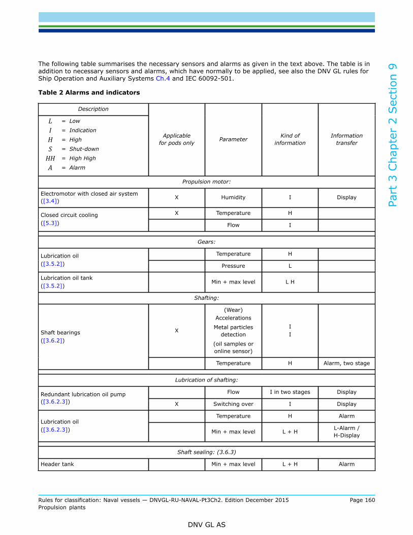
Part
3 C
hapt
er 2
Sec
tion
9
Rules for classification: Naval vessels — DNVGL-RU-NAVAL-Pt3Ch2. Edition December 2015 Page 160Propulsion plants
DNV GL AS
The following table summarises the necessary sensors and alarms as given in the text above. The table is inaddition to necessary sensors and alarms, which have normally to be applied, see also the DNV GL rules forShip Operation and Auxiliary Systems Ch.4 and IEC 60092-501.
Table 2 Alarms and indicators
Description
L = Low
I = Indication
H = High
S = Shut-down
HH = High High
A = Alarm
Applicablefor pods only Parameter Kind of
informationInformation
transfer
Propulsion motor:
Electromotor with closed air system([3.4]) X Humidity I Display
X Temperature HClosed circuit cooling([5.3]) Flow I
Gears:
Temperature HLubrication oil([3.5.2]) Pressure L
Lubrication oil tank([3.5.2])
Min + max level L H
Shafting:
X
(Wear)Accelerations
Metal particlesdetection
(oil samples oronline sensor)
IIShaft bearings
([3.6.2])
Temperature H Alarm, two stage
Lubrication of shafting:
Flow I in two stages DisplayRedundant lubrication oil pump([3.6.2.3]) X Switching over I Display
Temperature H AlarmLubrication oil([3.6.2.3]) Min + max level L + H L-Alarm /
H-Display
Shaft sealing: (3.6.3)
Header tank Min + max level L + H Alarm

Part
3 C
hapt
er 2
Sec
tion
9
Rules for classification: Naval vessels — DNVGL-RU-NAVAL-Pt3Ch2. Edition December 2015 Page 161Propulsion plants
DNV GL AS
Description
L = Low
I = Indication
H = High
S = Shut-down
HH = High High
A = Alarm
Applicablefor pods only Parameter Kind of
informationInformation
transfer
Any leakage Leakage H Alarm
Emergency sealing device X operability I Alarm (if fault)
Shaft movement:
Locking device for propeller shaft([3.6.4.1]) Engagement I Display
Clutch for power transmission([3.6.4.2]) Engagement I Display
Bilge system: (3.7.2)
Liquid in gondola X Bilge level H HH Alarm, two stage
Liquid in gondola X Bilge levelmonitoring L HH Alarm, S
Liquid in motor X Bilge level H HH Alarm, twostage, S
Steering device:
Control components([4.7.2])
Failure I Alarm
Steering angle limitation([4.7.3])
Failure I Display
Hydraulic systems:
Permissible oil level in tanks ([6.5]) Level L H Display
Electrical systems:
Comparing of redundant parametersfor measurement([7.1.1])
Missing plausibility I Display
Data transmission([7.1.4])
Signal fault I Display
Critical situations([7.1.5])
X Occurrence I Display
Fire alarm([7.2.2])
X Smoke detected I Display

Part
3 C
hapt
er 2
Sec
tion
9
Rules for classification: Naval vessels — DNVGL-RU-NAVAL-Pt3Ch2. Edition December 2015 Page 162Propulsion plants
DNV GL AS
7.1.3 Safety systemsAll signals leading to or requesting a shut-down or an essential emergency action shall be produced andtransferred independently from the operation and the alarm system.The requirements of the DNV GL rules for Electrical Installations Ch.3 Sec.9 [3] have to be complied withanalogously.
7.1.4 Data transmission (podded drives only)Within the approval process of the slip ring unit, a check of the data transmitting system has to be included.Special emphasis shall be put on the influence of the special electromagnetic environment.If signals are transferred via components of the slip ring unit, those components have to be realisedredundantly. A fault in a signal line has to be alarmed.
7.1.5 If for podded drives critical situations may occur, they have to be indicated by a two stage alarm.The crew shall be enabled to identify the problem and to take actions.
7.2 Further requirements
7.2.1 For further requirements of the electrical installations see the DNV GL rules for Electrical InstallationsCh.3 Sec.13.
7.2.2 Fire alarm (podded drives only)The area above the slip ring unit and accessible areas have to be equipped with smoke detectors.
7.2.3 Accessible areasAccessible areas, normally used for maintenance work, have to be equipped with sufficient illumination andventilation. The access has to be locked to avoid any hazard to the staff.
8 Testing and trials
8.1 Quality assurance and inspection planTesting and supervision have to be performed according to the quality assurance and inspection planapproved by the Society.
8.2 Testing and supervision during construction8.2.1 Material certification and approval of componentsThe certification of the material for essential components and their inspection and testing are summarized inTable 3.
8.2.2 Testing of power units for propulsion or steering
8.2.2.1 The power units are required to undergo tests on a test stand in the manufacturer's works.For diesel engines see Sec.3.For electric motors see DNV GL rules for Electrical Installations Ch.3 Sec.14.
8.2.2.2 For hydraulic pumps and motors, the RU SHIP Pt.4 Ch.6 Sec.9 [2], are to be applied analogously.Where the drive power is 50 kW or more, this testing is to be carried out in the presence of a surveyor.

Part
3 C
hapt
er 2
Sec
tion
9
Rules for classification: Naval vessels — DNVGL-RU-NAVAL-Pt3Ch2. Edition December 2015 Page 163Propulsion plants
DNV GL AS
8.2.3 Pressure and tightness testsPressure components are to undergo a pressure test.
The test pressure pp is
pp = 1.5 · pe,zul
pe,zul = is the maximum allowable working pressure [bar] = the pressure at which the relief valves open.However, for working pressures above 200 bar the test pressure need not exceed p + 100 bar
For pressure testing of pipes, their valves and fittings, see the DNV GL rules for Ship Operation Installationsand Auxiliary Systems Ch.4 Sec.8.
Tightness tests are to be performed on components to which this is appropriate (e.g. gondola of a poddeddrive).
Table 3 Certification and approval of components
Certificate 2
Component, Assembly group 1Material Component,
Final
Special approval tests
Steering foundation plate B B
Slewing bearing B A Ultrasonic test, true running test, bearingtolerances
Planetary gear for slewing motor B A Final testing and inspection
Slewing gear A A Contact pattern, visual inspection
Hydraulic power pack– for steering motors
– for CPPA A
Pipes and hoses see RU SHIP Pt.4 Ch.10Sec.1 [2.10].Function test, pressure test
Hydraulic motorAzimuthing drive
A ASee RU SHIP Pt.4 Ch.5 Sec.3 [1.4.2].Function test, pressure test
Converter and power transmission forazimuthing motor A A See Ch.3 Sec.2 [3].
Electrical motorAzimuthing drive
A A See Ch.3 Sec.14 [2].
Azimuthing locking device B B Final inspection and functional test theSociety
Cone, well section and major housing partstransmitting thrust
Ametal plate
A Final inspection after heat treatment andsand blasting:
Pod cone complete with electrical andhydraulic installation A Final inspection by the Society, FAT
Pod casing (gondola) rawcasting: A A
Visual inspection, pressure and ultrasonictestAfter machining surface crack detectiontest and dimension protocol
Slewing seal B A Same as stern tube seal
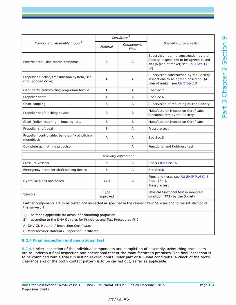
Part
3 C
hapt
er 2
Sec
tion
9
Rules for classification: Naval vessels — DNVGL-RU-NAVAL-Pt3Ch2. Edition December 2015 Page 164Propulsion plants
DNV GL AS
Certificate 2
Component, Assembly group 1Material Component,
Final
Special approval tests
Electric propulsion motor, complete A A
Supervision during construction by theSociety, inspections to be agreed basedon QA plan of maker, see Ch.3 Sec.14[2].
Propulsor electric, transmission system, slipring (podded drive) A A
Supervision construction by the Society,inspections to be agreed based on QAplan of maker, see Ch.3 Sec.13
Gear parts, transmitting propulsion torque A A See Sec.7
Propeller shaft A A See Sec.6
Shaft coupling A A Supervision of mounting by the Society
Propeller shaft locking device B B Manufacturer Inspection Certificate,functional test by the Society
Shaft (roller-)bearing + housing, etc. B B Manufacturer Inspection Certificate
Propeller shaft seal B A Pressure test
Propeller, controllable, build-up fixed pitch ormonoblock A A See Sec.8
Complete azimuthing propulsor A Functional and tightness test
Auxiliary equipment
Pressure vessels A A See s Ch.5 Sec.16
Emergency propeller shaft sealing device B A See Sec.6
Hydraulic pipes and hoses B / A APipes and hoses see RU SHIP Pt.4 C. 5Sec.1 [8.4].Pressure test
Sensors Typeapproved
Physical functional test in mountedcondition (FAT) by the Society
Further components are to be tested and inspected as specified in the relevant DNV GL rules and to the satisfaction ofthe surveyor!
1) as far as applicable for actual of azimuthing propulsor2) according to the DNV GL rules for Principles and Test Procedures Pt.2.
A: DNV GL Material / Inspection Certificate,
B: Manufacturer Material / Inspection Certificate
8.2.4 Final inspection and operational test
8.2.4.1 After inspection of the individual components and completion of assembly, azimuthing propulsorsare to undergo a final inspection and operational test at the manufacturer’s premises. The final inspection isto be combined with a trial run lasting several hours under part or full-load conditions. A check of the toothclearance and of the tooth contact pattern is to be carried out, as far as applicable.

Part
3 C
hapt
er 2
Sec
tion
9
Rules for classification: Naval vessels — DNVGL-RU-NAVAL-Pt3Ch2. Edition December 2015 Page 165Propulsion plants
DNV GL AS
8.2.4.2 If no suitable test bed is available for the operational and load testing of azimuthing propulsors, thetests can be carried out on the occasion of the dock test or sea trials.
8.2.4.3 Limitations on the scope of the tests require the Society's consent.
8.3 Sea trials
8.3.1 The scope of sea trials for azimuthing and podded propulsors is defined in Table 4.
8.3.2 The faultless operation, smooth running and bearing temperatures of the gears and control system areto be checked during the sea trials under all steaming conditions.
8.3.3 After the conclusion of the sea trials, the toothing is to be examined through the inspection openingsand the contact pattern is to be checked. The tooth contact pattern is to be assessed on the basis of thereference values for the percentage area of contact given in Sec.7 Table 6.The scope of the check on contact pattern following the sea trials may be limited with the surveyor'sagreement provided that the checks on contact pattern called for in [8.2.4.1] and [8.2.4.2] have beensatisfactory.
8.3.4 After successful sea trials the final motor parameters and all other relevant data of the podded driveshave to be stamped on the podded drive poster. The power has to be calculated for the highest water andengine room temperature, based on the sea trial data. The calculation has to be submitted to the Society forapproval.
Table 4 Scope of sea trials
Test group/test Sub-test Test remarks
a) Testing of sensor for angle measurement in sea/harbour mode
b) Testing of switch over from sea to harbour modeand vice versa
Ship speed, rpm, steering angle,etc. to be checked
c) Testing of steering angle limitation (sea / harbourmode) and associated reductions Reductions: power, rpm
d) Testing whether extreme, but possiblemanoeuvres could endanger the ship or not
Verification or correction oflimitations
e) Testing of locking of steering drive and emergencypositioning
f) Testing of steering drive failure Check of auxiliary drive, brakeand overload clutch
1. Slewing mechanism
g) Wear down measurement of the slewing bearing As basic measurement
2. Steering manoeuvres Steering manoeuvres acc. to Ch.5 Sec.2 [2]. Compare also SOLAS II-1, Reg.29
3. Run out testCheck of ships course stability and down to whichspeed an inactive azimuthing pro-pulsor caninfluence the course of the ship
4. Propeller shaft lock
5. Loss of propulsion of one pod

Part
3 C
hapt
er 2
Sec
tion
9
Rules for classification: Naval vessels — DNVGL-RU-NAVAL-Pt3Ch2. Edition December 2015 Page 166Propulsion plants
DNV GL AS
Test group/test Sub-test Test remarks
a) Testing to fulfil requirements acc. to SOLAS
b) Testing under adverse conditions Manual operation6. Crash stop
c) Testing of the automated procedure Only as far as applicable
7. Endurance test
8. Test of motor reversing
9. Manoeuvring tests accordingto DNV GL rules
10. Test of local control stations
a) Measured and monitored data have to berecorded during the complete sea trials
Power, bearing temperature,vibrations, etc. to be measured
b) Quality of electrical current DNV GL rules for ElectricalInstallations Ch.3
11. Test of operationalcondition monitoring
c) Envelope of bearing vibrations Podded drives only

Part
3 C
hapt
er 2
Sec
tion
10
Rules for classification: Naval vessels — DNVGL-RU-NAVAL-Pt3Ch2. Edition December 2015 Page 167Propulsion plants
DNV GL AS
SECTION 10 TORSIONAL VIBRATIONS
1 General
1.1 ScopeThe requirements of this Section apply to the components of the main shafting system and to essentialequipment, compare Sec.1 [2.5].These rules may be applied analogously for rudder propeller units driven by internal combustion engines.They are not applicable for electrically driven azimuthing propulsors (fixed or turnable).
1.2 Definitions
1.2.1 For the purposes of these rules, torsional vibration stresses are additional loads due to torsionalvibrations. They result from the alternating torque which is superimposed on the mean torque.
1.2.2 The speed range in which the plant can be operated continuously is the service speed range. It coversthe range between nmin (minimum speed) and 1.05 nN (nominal speed).
2 Calculation of torsional vibrations
2.1 A torsional vibration analysis covering the torsional vibration stresses to be expected in the main shaftingsystem including its branches is to be submitted to the Society for approval. To facilitate a smooth andefficient approval process they should be submitted electronically via MY DNV GL . In specific cases andfollowing prior agreement with the Society they can also be submitted in paper form in triplicate.The following data shall be included in the analysis: Input data:
— equivalent torsional vibration system— comprising moments of inertia and inertialess torsional elasticities/stiffnesses for the complete system— prime mover— engine type, rated power, rated speed, cycles per revolution, design (in line, V-type, etc.), number of
cylinders, firing order, cylinder diameter, stroke, stroke to connecting rod ratio, oscillating mass of onecrank gear, excitation spectrum of engine in form of tangential coefficients (for new/unconventional typesof engines)
— vibration damper— type, damping coefficient, moments of inertia, dynamic stiffness— elastic couplings— type, damping coefficient, moments of inertia, dynamic stiffness— reduction/power intake off (PTO) gears— type, moment of inertia for wheels and pinions, individual gear’s ratios per mesh, effective stiffness— shafting— shaft diameter of crankshafts, intermediate shafts, gear shafts, thrust shafts and propeller shafts— propeller— type, diameter, number of blades, pitch and expanded area ratio, moment of inertia in air, moment of
inertia of entrained water (for Zero and full pitch for CP propellers)

Part
3 C
hapt
er 2
Sec
tion
10
Rules for classification: Naval vessels — DNVGL-RU-NAVAL-Pt3Ch2. Edition December 2015 Page 168Propulsion plants
DNV GL AS
Output data/results:
— natural frequencies— with their relevant vibration forms (modes)— forced vibratory loads (torques or stresses)— estimated torsional vibration torques/shear stresses in all important elements of the system with
particular reference to clearly defined resonance speeds for the whole operating speed range. The resultsshall include the synthesised values (vectorial sum over all harmonics) for the torques/stresses.
2.2 The calculations are to be performed both for normal operation (uniform pressure distribution over allcylinders or small deviations in the pressure distribution e.g. ± 5%) and misfiring operation (one cylinderwithout ignition, compression of the cylinder still existing).
2.3 Where the installation allows various operation modes, the torsional vibration characteristics are to beinvestigated for all possible modes, e.g. in installations fitted with controllable pitch propellers for zero andfull pitch, with power take off gear integrated in the main gear or at the forward crankshaft end for loadedand idling generator, with clutches for engaged and disengaged branches.
2.4 The calculation of torsional vibrations shall also include the stresses/torques resulting from thesuperimposition of several harmonics (synthesised values) so far relevant for the overall assessment of thesystem, see also [2.1], output data.
2.5 If modifications are introduced into the system which have a substantial effect on the torsional vibrationcharacteristics, the calculation of the torsional vibrations is to be repeated and re-submitted for approval.
2.6 Where an electrical machine, e.g. static converter controlled motors, can generate periodic excitation leadingto relevant torsional vibration stresses in the system as a whole, this is to be taken into account in thecalculation of the forced torsional vibration. The manufacturer of the electrical machine is responsible fordefining the excitation spectrum in a suitable manner for performing forced torsional vibration calculations.
3 Permissible torsional vibration stressesGuidance note:Naval ships are commonly equipped with geared propulsion plants. For such plants the stresses in the shafting are in general irrelevantfor design purposes. The evaluation of the torsional behaviour should concentrate on the torsional loading of crankshaft, gears andflexible couplings.
---e-n-d---of---g-u-i-d-a-n-c-e---n-o-t-e---
3.1 ShaftingIn no part of the shafting may the alternating torsional vibration stresses exceed the following values of τ1 forcontinuous operation or of τ2 under transient conditions. Figure 1 indicates the τ1 and τ2 limits as a reference

Part
3 C
hapt
er 2
Sec
tion
10
Rules for classification: Naval vessels — DNVGL-RU-NAVAL-Pt3Ch2. Edition December 2015 Page 169Propulsion plants
DNV GL AS
for intermediate and propeller shafts of common design and for the location deemed to be most severelystressed (cK = 0.55 or cK = 0.45 for propeller shafts, and cK = 1.0 and cK = 0.8 for intermediate shafts). Thelimits depend on the design and the location considered and may in particular cases lie outside the indicatedranges according to Figure 1. They are to be determined in accordance with equations (1) - (4) and Table 1.
Speed ranges in the n/no ≤ 0.8 area, in which the permissible values of τ1 for continuous operation areexceeded shall be crossed through quickly (barred speed ranges for continuous operation), provided that thelimit for transient operation τ2 is not exceeded.
[N/mm2] (1)
for speed ration values λ < 0.9
[N/mm2] (2)
where 0.9 ≤ λ ≤ 1.05
[N/mm2] (3a)
Alternatively and depending on the material and design the following formula may be used instead (3a)
(3b)
d = shaft diameter [mm]ℓ = speed ratio [–]
= n/no
n = speed [min–1]no = nominal speed [min–1]Rm = tensile strength of shaft material [N/mm2]cw = material factor [–]
= (4)
For the purpose of the formulas (1), (2), (3a), (3b) the tensile strength calculation value applied shall notexceed the following limits:

Part
3 C
hapt
er 2
Sec
tion
10
Rules for classification: Naval vessels — DNVGL-RU-NAVAL-Pt3Ch2. Edition December 2015 Page 170Propulsion plants
DNV GL AS
Rm = 600 N/mm2
– for propeller shafts in general– for other shafts particularly intermediate shafts, made of forged, low alloy carbon or carbonmanganese steel
Rm = 800 N/mm2
– for all shafts except propeller shafts made of forged high alloy steels. Formula (3a) should beapplied in conjunction with such steels and special design features only.
cD = size factor [–]0.35 + 0.93 · d–0.2
cK = form factor [–]for intermediate and propeller shafts depending on details of design and construction of appliedmechanical joints in the shaft line. The value of cK is given in Table 1.
3.2 Crankshafts
3.2.1 Crankshafts applied for engines for ships classed by the Society shall be approved on the basis of RUSHIP Pt.4 Ch.3 Sec.1 [2.5]. For application of this guideline a gas pressure distribution in the cylinder overthe crank angle is submitted by the maker of the engine. The maker of the engine also applies for approvalof a maximal additional (vibratory) shear stress, which is referred to the crank with the highest load dueto mean torque and bending forces. Normally this approved additional shear stress may be applied for firstevaluation of the calculated vibratory stresses in the crankshaft via the torsional vibration model. Commonvalues are between 30 and 90 N/mm2 for medium and high speed engines; but special confirmation of thevalue considered for judgement by the Society is necessary.For further details see also Sec.3 [3.1].
3.2.2 When the generally approved limit for the vibratory stresses for the crankshaft of the engine as definedunder [3.2.1] is exceeded, special considerations may be applied to define a higher limit for the specialinvestigated case. For this detailed system calculations (combined axial / torsional model) and application ofthe actual calculated data within the model in accordance to RU SHIP Pt.4 Ch.3 Sec.1 [2.5], as quoted under[3.2.1] are necessary.
3.2.3 Torsional vibration dampers which are aiming to reduce the stresses in the crankshaft shall be suitablefor use for diesel engines. The Society reserves the right to call for proof of this, compare also [6].Torsional vibration dampers shall be capable of being checked for performance ability in the assembledcondition or shall be capable of being dismounted with reasonable ease for checking purposes. Thisrequirement does not apply for small medium or high speed engines, so far the exchange of the damper isa part of the regular service of the engine and a fixed exchange interval is part of the engine’s crankshaftapproval.
3.3 Gears
3.3.1 In the service speed range 0.9 ≤ λ ≤ 1.05, no alternating torque higher than 30% of the meannominal torque for this stage shall normally occur in any loaded gear’s mesh. In general the value for themaximum mean torque transmitted by the gear stage has to be applied for evaluation purposes as the meannominal torque.If the gearing is demonstrably designed for a higher power, then, in agreement with the Society, 30% of thedesign torque of the concerned gear’s mesh may be applied as admissible.
3.3.2 When passing through resonant speeds below the operational speed range during starting andstopping of the plant, the alternating torque in the gear shall not exceed twice the nominal mean torque forwhich the gear has been designed.

Part
3 C
hapt
er 2
Sec
tion
10
Rules for classification: Naval vessels — DNVGL-RU-NAVAL-Pt3Ch2. Edition December 2015 Page 171Propulsion plants
DNV GL AS
3.3.3 Load reversal due to alternating torques is normally permitted only while passing through the lowerspeed range up to λ ≤ 0.35.If, in special cases, gear hammering within the operational speed range, is unavoidable, a barred speedrange in accordance with [5.1] is to due to be specified.This requirement does not apply to gear stages which run without load (e.g. the idling stage of a reversinggear or the idling gears of an unloaded shaft-driven generator). These are covered by the provisions inaccordance to [3.3.4]
3.3.4 In installations where parts of the gear train run without load, the torsional vibration torque incontinuous operation shall not exceed 20% of the nominal torque in order to avoid unacceptable stresses dueto gear hammering. This applies not only to gear stages but also to parts which are particularly subject totorsional vibrations (e.g. multiple-disc clutch carriers). For loaded parts of the gear system the provisions inaccordance to [3.3.1] apply.Higher alternating torques may be approved by the Society if proof is submitted that measures have beenintroduced considering these higher loadings see [3.3.1].
3.4 Flexible couplings
3.4.1 Flexible couplings shall be designed to withstand the torsional vibration loads which occur inthe operation of the ship. In this context, the total load resulting, in accordance with [2.4], from thesuperimposition of several orders is to be taken into account, see also Sec.7.
3.4.2 Flexible couplings shall be capable to take in higher alternating torque which can occur duringdeviation from normal operation according to [2.2], during continuous operation within the service speedrange.Speed ranges within which, under abnormal operating conditions, continuous operation is not allowed shallbe indicated in accordance with [5.2].
3.5 Shaft-driven generators
3.5.1 In installations with generators directly coupled to the engine (free crankshaft end) it is necessary toensure that the accelerations do not exceed the values prescribed by the manufacturer in any part of thegenerator.The applicable criterion in such cases shall be the tangential acceleration, which is the product of the angularacceleration and the effective radius. The angular acceleration is determined by means of forced torsionalvibrations calculations and is to be regarded as the synthesised value of all major orders. However, formarked points of resonance the value of the individual harmonics may be used instead for assessment.
3.5.2 The torsional vibration amplitude (angle) of shaft-driven generators shall normally not exceed anelectrical value of ± 5°. The electrical vibration amplitude is obtained by multiplying the mechanical vibrationamplitude by the number of pole pairs. Whether the Society is able to permit higher values depends on theconfiguration of the ship's electrical system.

Part
3 C
hapt
er 2
Sec
tion
10
Rules for classification: Naval vessels — DNVGL-RU-NAVAL-Pt3Ch2. Edition December 2015 Page 172Propulsion plants
DNV GL AS
Figure 1 Permissible torsional vibration stresses in shafting systems in accordance with formulas(1) – (3) for shaft materials with a tensile strength of 450 N/mm2
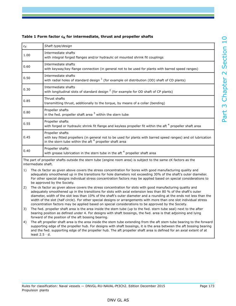
Part
3 C
hapt
er 2
Sec
tion
10
Rules for classification: Naval vessels — DNVGL-RU-NAVAL-Pt3Ch2. Edition December 2015 Page 173Propulsion plants
DNV GL AS
Table 1 Form factor cK for intermediate, thrust and propeller shafts
cK Shaft type/design
1.00Intermediate shaftswith integral forged flanges and/or hydraulic oil mounted shrink fit couplings
0.60Intermediate shaftswith keyway/key flange connection (in general not to be used for plants with barred speed ranges)
0.50Intermediate shaftswith radial holes of standard design 1 (for example oil distribution (OD) shaft of CD plants)
0.30Intermediate shaftswith longitudinal slots of standard design 2 (for example for OD shaft of CP plants)
0.85Thrust shaftstransmitting thrust, additionally to the torque, by means of a collar (bending)
0.80Propeller shaftsin the fwd. propeller shaft area 3 within the stern tube
0.55Propeller shaftswith forged or hydraulic shrink fit flange and keyless propeller fit within the aft 4 propeller shaft area
0.45Propeller shaftswith key fitted propellers (in general not to be used for plants with barred speed ranges) and oil lubricationin the stern tube within the aft 4 propeller shaft area
0.40Propeller shaftswith grease lubrication in the stern tube in the aft 4 propeller shaft area
The part of propeller shafts outside the stern tube (engine room area) is subject to the same cK factors as theintermediate shaft.
1) The ck factor as given above covers the stress concentration for bores with good manufacturing quality andadequately smoothened up in the transitions for hole diameters not exceeding 30% of the shaft's outer diameter.For other special designs individual stress concentration factors may be applied based on special considerations tobe approved by the Society.
2) The ck factor as given above covers the stress concentration for slots with good manufacturing quality andadequately smoothened up in the transitions for slots with axial extension less than 80 % of the shaft's outerdiameter, width of the slot less than 10% of the shaft's outer diameter and a rounding at the ends not less than thewidth of the slot (half circle). For other special designs or arrangements with more than one slot individual stressconcentration factors may be applied based on special considerations to be approved by the Society.
3) The fwd. propeller shaft area is the area inside the stem tube (up to the fwd. stern tube seal) next to the afterbearing position as defined under 4. For designs with shaft bossings, the fwd. area is that adjoining and lyingforward of the position of the aft bossing bearing.
4) The aft propeller shaft area is the area inside the stem tube extending from the aft stem tube bearing to the forwardsupporting edge of the propeller hub. For designs with shaft bossings, it is the area between the aft bossing bearingand the fwd. supporting edge of the propeller hub. The aft propeller shaft area is defined for an axial extent of atleast 2.5 ∙ d.

Part
3 C
hapt
er 2
Sec
tion
10
Rules for classification: Naval vessels — DNVGL-RU-NAVAL-Pt3Ch2. Edition December 2015 Page 174Propulsion plants
DNV GL AS
3.6 Connected units
3.6.1 If further units, e.g. power turbines or compressors, are coupled positively or non-positively to themain propulsion system, due attention is to be paid to these when establishing the torsional vibrationloadings.In the assessment of their dynamic loads, the limits defined by the respective makers are to be consideredin addition to the criteria as stated in [3.1]. If these limits are exceeded, the units concerned are to bedisengaged or prohibited ranges of operation in accordance with [5.1] are to be declared. Disengaging ofthese units shall generally not lead to substantial overloading of the main system in terms of exceeding theτ2 limit for shafting systems, the maximum torque for flexible couplings or similar low cycle criteria for othercomponents.
3.6.2 In special critical cases, the calculations of forced torsional vibrations, including those for disturbedoperation (dismounted unit), as stated in [2.1] will be required to be submitted to the Society. In such casesthe Society reserves the right to stipulate the performance of confirmatory measurements, see 4, includingsuch as related to disturbed operation.
4 Torsional vibration measurements
4.1 During the ship's sea trials, the torsional vibrations of the propulsion plant are to be measured over thewhole operating range. Measuring investigations shall cover the normal as well as the misfiring condition.Speed ranges, which have been declared as barred speed ranges in accordance with [5.1] for misfiringoperation shall not be investigated by measurements, as far as these ranges are finally declared as "barred"on the base of reliable and approved calculations and adequately documented.Measurements are required by the Society for all plants with a nominal torque exceeding 40 kNm. For otherplants not meeting this condition, the Society reserve the right to ask for measurements depending on thecalculation results. The requirement for measurements will be communicated to the yard/engine supplier withthe approval letter for the torsional vibration calculation.Where measurements of identical propulsion plants (specifically sister ships) are available, further torsionalvibration measurements for repeat ships may, with the consent of the Society, be dispensed with.In case that the measuring results are not conclusive enough in respect to the calculations, the Societyreserves the right to ask for further investigations or new approval of a revised and adapted calculationmodel.
4.2 Where existing propulsion plants are modified, the Society reserves the right to require a renewedinvestigation of the torsional vibration characteristics.
5 Prohibited ranges of operation
5.1 Operating ranges, which due to the magnitude of the torsional vibration stresses and/or torques may onlybe passed through quickly (transient operation), are to be indicated as prohibited ranges of operation by redmarks on the tachometer or in some other suitable manner at the operating station.In normal operation the speed range λ ≥ 0.8 is to be kept free of prohibited ranges of operation.

Part
3 C
hapt
er 2
Sec
tion
10
Rules for classification: Naval vessels — DNVGL-RU-NAVAL-Pt3Ch2. Edition December 2015 Page 175Propulsion plants
DNV GL AS
In specifying prohibited ranges of operation it has to be observed that the navigating and manoeuvringfunctions are not severely restricted. The width of the barred speed range(s) is (are) to be selected in away that the stresses in the shafting do not exceed the permissible τ1 limit for continuous operation withan adequate allowance considering the inaccuracies of the tachometers and the speed setting devices. Forgeared plants the barred speed ranges, if any, refer to the gear meshes and elastic couplings and are to bedetermined in the same way with reference to the permissible vibratory torques or permissible power loss forthese components (see also [3.4] and [3.5]).
5.2 Measures necessary to avoid overloading of the propulsion plant under abnormal operating conditions are tobe displayed on instruction plates to be affixed to all engine control stations.
6 Auxiliary machinery
6.1 Essential auxiliary machinery such as diesel generators, bow thrusters and other units driven by internalcombustion engines shall be designed in a way that the service speed range is free of unacceptable stressesdue to torsional vibrations in accordance with [3]
6.2 Generators
6.2.1 For diesel generator sets with a mechanical output of more than 150 kW torsional vibration calculationsshall be submitted to the Society for approval. The investigations shall include natural frequencies as well asforced vibration calculations. The speed range 90% to 105% of the nominal speed shall be investigated underfull load conditions (nominal excitation).
6.2.2 For rigidly coupled generators (without elastic coupling) the vibratory torque in the input part of thegenerator's shaft shall not exceed 250% of the nominal torque. For the purposes of these rules nominaltorque is the torque which can be calculated by applying the actual data of the diesel engine (nominaloutput / nominal speed).The compliance of the limit of 250% within the speed range 90% to 105% of the nominal speed shall beproven. The calculation for this speed range shall be carried out by using the excitation corresponding to thenominal torque of the engine.Exceeding the limit of 250% may be considered in exceptional cases, provided that the generator'smanufacturer has designed the generator for a higher dynamical torque. But also in such cases a highestvalue of 300% of the actual nominal torque of the set as defined above shall not be exceeded.
6.3 Bow thruster
6.3.1 For bow thrusters as well as for further essential auxiliary machinery driven by diesel engines witha mechanical output higher than 150 kW, natural as well as forced torsional vibration calculations shall besubmitted to v for approval. The torsional vibration calculation shall focus on the real load profile of tge set.
6.3.2 For bow thrusters as well as for further essential auxiliary machinery driven by electrical motor thesupplier shall take care that relevant excitation forces (e.g. propeller blade frequency or similar), may notlead to unacceptable torsional vibration loadings. In special cases the Society may require the submission ofcorresponding calculations.

Part
3 C
hapt
er 2
Sec
tion
11
Rules for classification: Naval vessels — DNVGL-RU-NAVAL-Pt3Ch2. Edition December 2015 Page 176Propulsion plants
DNV GL AS
SECTION 11 INTENTIONALLY LEFT BLANK
1 Intentionally left blank

Part
3 C
hapt
er 2
Sec
tion
12
Rules for classification: Naval vessels — DNVGL-RU-NAVAL-Pt3Ch2. Edition December 2015 Page 177Propulsion plants
DNV GL AS
SECTION 12 SPARE PARTS
1 General
1.1 In order to be able to restore engine operation and manoeuvring capacity to the ship in the event of damageat sea spare parts for the main drive and the essential equipment (see Sec.1 [2.5)) are to be carried onboard every ship, together with the necessary tools.These requirements are considered to be complied with if the range of spare parts corresponds to thefollowing tables considering the extent of the actually installed systems and components at the time ofcommissioning.
1.2 Depending on the design and arrangement of the engine plant, the intended service and operation of theship, and also the manufacturer's recommendations, a different volume of spare parts may be agreedbetween the naval administration and the Society.Where the volume of spare parts is based on special arrangements between the naval administration and theSociety, technical documentation is to be provided.A list of the relevant spare parts is to be carried on board.
1.3 In the case of propulsion systems and essential equipment which are not included in the following tables,the requisite range of spare parts is to be established in each individual case between naval administration,shipyard and the Society.
2 Volume of Spare PartsThe volume of spare parts in accordance with the tables below is classified according to different ranges ofservice:
A = Unlimited range of service and RSA (200)B = All other ranges of service
Explanations:
RSA (200) (Restricted International Service)This range of service is limited, in general, to trade along the coast, provided that thedistance to the nearest port of refuge and the offshore distance do not exceed 200nautical miles. This applies also to trade in the North Sea and within enclosed seas, suchas the Mediterranean, the Black Sea and waters with similar seaway conditions. Trade toIceland, Spitsbergen and the Azores is exempted.
RSA (50) (Coastal Service)This range of service is limited, in general, to trade along the coasts, provided thatthe distance to the nearest port of refuge and the offshore distance do not exceed 50nautical miles. This applies also to trade within enclosed seas, such as the Baltic Sea andwaters with similar seaway conditions.

Part
3 C
hapt
er 2
Sec
tion
12
Rules for classification: Naval vessels — DNVGL-RU-NAVAL-Pt3Ch2. Edition December 2015 Page 178Propulsion plants
DNV GL AS
RSA (SW) (Sheltered Water Service)This range of service is limited to trade in shoals, bays, haffs and firths or similar waterswhere heavy seas do not occur.
2.1 Internal combustion enginesFor internal combustion engines, see Sec.3, the volume of spare parts is defined in Table 1 to Table 3.
2.2 Gas turbinesFor gas turbines see Sec.4, the volume of spare parts is defined in Table 4.
2.3 Gears and thrust bearingsFor gears and thrust bearings in propulsion plants see Sec.7, the volume of spare parts is defined in Table 5.
2.4 Air compressors for essential servicesFor air compressors, see Ch.5 Sec.6 [12] and Sec.6 [18], the volume of spare parts is defined in Table 6.
2.5 PumpsFor pumps see the DNV GL rules for Ship Operation Installations and Auxiliary Systems Ch.5 Sec.8, thevolume of spare parts is defined in Table 7.
2.6 Hydraulic systemsFor hydraulic systems see the DNV GL rules for Ship Operation Installations and Auxiliary Systems, Ch.5Sec.14 the volume of spare parts is defined in Table 8.
2.7 Other spare partsFor other spare parts for main and auxiliary engines the volume is defined in Table 9.
Table 1 Spare parts for main engines 1, 4, 5, 6
Range of spare parts A B
Main bearings Main bearings or shells for one bearing of each size and type fitted,complete with shims, bolts and nuts 1
1 set 1 setMain thrust block(integral)
Pads for “ahead” face of Michell type thrust block, or complete whitemetal thrust shoe of solid ring type 1 1
Bottom end bearings or shell of each size and type fitted, complete withshims, bolts and nuts, for one cylinders 1 set −
Connecting rodbearings Trunk piston type:
Gudgeon pin complete with bush/bearing shells and securing rings forone cylinder
1 set −
Cylinder liner Cylinder liner, complete, fully equipped and ready for installation incl.gaskets 1 −

Part
3 C
hapt
er 2
Sec
tion
12
Rules for classification: Naval vessels — DNVGL-RU-NAVAL-Pt3Ch2. Edition December 2015 Page 179Propulsion plants
DNV GL AS
Range of spare parts A B
Cylinder cover, complete, fully equipped and ready for installation,including gaskets 1 −
Cylinder cover
Cylinder cover bolts and nuts, for one cylinder ¼ set −
Exhaust valves, with full equipment and ready for installation, for onecylinder 1 set 1 set
Inlet valves, with full equipment and ready for installation, for onecylinder 1 set 1 set
Starting air valve, with full equipment and ready for installation 1 1
Overpressure control valve, complete 1 1
Valves
Fuel injection valves of each type, ready for installation, for one engine 2 1 set ¼ set
Hydraulic valve drive High-pressure pipe/hose of each type 1 −
Range of spare parts A B
Piston:Trunk piston type
Piston of each type, ready for fitting, with piston rings, gudgeon pin,connecting rod, bolts and nuts 1 −
Piston rings Piston rings for one cylinder 1 set −
Piston cooling Articulated or telescopic cooling pipes and fittings for one cylinder 1 set −
Cylinder lubricator Scope of spare parts to be defined with regard to lubricator design andsubject to approval 1 −
Fuel injection pumpsFuel injection pump complete or, when replacement of individualcomponents at sea is practicable, complete pump element withassociated valves, seals, springs, etc. or higher pressure fuel pump
1 −
Fuel injections pipes High pressure fuel pipe of each size and shape fitted, complete withcouplings 1 −
Auxiliary blower, complete including drive 1 −
Charge air system 3Exhaust-gas turbocharger:rotor complete with bearings,
nozzle
rings and attached lube oil pump
1 set −
Suction and pressure valves of each type for one cylinder 1 set −
Gaskets and packings Special gaskets and packings of each type for cylinder covers andcylinder liners, for one cylinder − 1 set
Exhaust gas system(engine-related) Compensator of each type 1 −

Part
3 C
hapt
er 2
Sec
tion
12
Rules for classification: Naval vessels — DNVGL-RU-NAVAL-Pt3Ch2. Edition December 2015 Page 180Propulsion plants
DNV GL AS
Range of spare parts A B
1) in the case of multi-engine installations, the minimum required spares are only necessary for one engine2) a) engines with one or two fuel-injection valves per cylinder:
one set of fuel valves, completeb) engines with more than two fuel injection valves per cylinder:
two valves complete per cylinder plus a corresponding number of valve parts (excluding the valve bodies)which make it possible to form a complete spare set by re-using the operational parts of the dismantled valves
3) spare parts for exhaust-gas turbocharger and auxiliary blower may be omitted if emergency operation of the mainengine after failure is demonstrably possible
The requisite blanking, bypass and blocking arrangements for the emergency operation of the main engine are to beavailable on board.
4) the necessary tools and equipment for fitting the required spare parts are to be available on board
5) spare parts are to be replaced immediately as soon as they are “used-up”
6) For electronically controlled engines spare parts as recommended by the engine manufacturer are to be provided.
Table 2 Spare parts for auxiliary engines driving electric generators for essential equipment
Range of spare parts A
Main bearings Bearings or shells for one bearing of each size and type fitted, complete with shims,bolts and nuts 1
Exhaust valves, complete with casings, seats, springs and other fittings for onecylinder 2 sets
Inlet valves, complete with casings, seats, springs and other fittings for one cylinder 1 set
Starting air valve, complete with casing, seat, springs and other fittings 1
Overpressure control valve, complete 1
Valves
Fuel valves of each size and type fitted, complete, with all fittings, for one engine 1/4 set
Bottom end bearings or shells of each type, complete with all fittings 1Connecting rodbearings Gudgeon pin with bush for one cylinder 1
Piston rings Piston rings, for one cylinder 1 set
Fuel injectionpumps
Fuel injection pump complete or, when replacement of individual components at seais practicable, complete pump element with associated valves, seals, springs, etc. orequivalent high pressure fuel pump
1
Fuel injection pipes High pressure fuel pipe of each size and shape fitted, complete with fittings 1
Gasket andpackings
Special gaskets and packings of each size and type fitted, for cylinder covers andcylinder liners for one cylinder 1 set
Note:
1) Where the number of generating sets (including stand-by units) is greater than called for by the rules, no spares arerequired for the auxiliary engines.
2) Where several diesel engines of the same type are installed by way of generator drive spare parts are required forone engine only.
3) No spares are required for the engines driving emergency generator sets4) For electronically controlled engines sp0are parts recommended by the engine manufacturer are to be provided.

Part
3 C
hapt
er 2
Sec
tion
12
Rules for classification: Naval vessels — DNVGL-RU-NAVAL-Pt3Ch2. Edition December 2015 Page 181Propulsion plants
DNV GL AS
Table 3 Spare parts for prime movers of essential equipment other than generators
Range of spare parts
The range of spare parts required for auxiliary drive machinery for essential consumers is to be specified in accordancewith Table 2
Note:Where an additional unit is provided for the same purpose no spare parts are required.
Table 4 Spare parts for gas turbines
Range of spare parts
For essential main propulsion: For each gas turbine a complete set of wear and tear parts, which can bechanged on board by a crew without considerable maintenance expertise.
For non-essential propulsion:defined
No spare parts prescribed by the Society. If applicable, to be by manufacturer.
For driving of auxiliaries: For two gas turbines each one set of wear and tear parts, which can bechanged on board by a crew without considerable maintenance expertise.
Table 5 Spare parts for gears and thrust bearings in propulsion plants
Range of spare parts A B
1 setWearing parts of gear-driven pump supplying lubricating oil to gears or one complete lubricatingoil pump if no stand-by pump is available 1
−
Thrust pads for ahead side of thrust bearings 1 set 1 set
Table 6 Spare parts for air compressors for essential services
Range of spare parts A B
Piston ring of each type and type fitted for one piston 1 set 1 set
Suction and delivery valves complete of each size and type ½ set ½ set
Note:For spare parts for refrigerant compressors, see Ch.5 Sec.12 [11].
Table 7 Spare parts for pumps
Range of spare parts A B
Valve with seats and springs each size fitted 1 set 1 set
Piston rings each type and size for one piston 1 set 1 setPiston pumps
Bearing of each type and size 1 1
Centrifugal pumps Rotor sealings of each type and size 1 1
Bearings of each type and size 1 1Gear and screwtype pumps Rotor sealings of each type and size 1 1
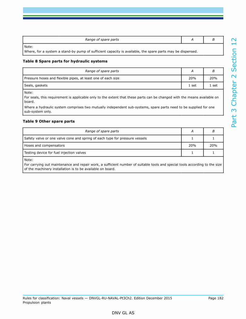
Part
3 C
hapt
er 2
Sec
tion
12
Rules for classification: Naval vessels — DNVGL-RU-NAVAL-Pt3Ch2. Edition December 2015 Page 182Propulsion plants
DNV GL AS
Range of spare parts A B
Note:Where, for a system a stand-by pump of sufficient capacity is available, the spare parts may be dispensed.
Table 8 Spare parts for hydraulic systems
Range of spare parts A B
Pressure hoses and flexible pipes, at least one of each size 20% 20%
Seals, gaskets 1 set 1 set
Note:For seals, this requirement is applicable only to the extent that these parts can be changed with the means available onboard.
Where a hydraulic system comprises two mutually independent sub-systems, spare parts need to be supplied for onesub-system only.
Table 9 Other spare parts
Range of spare parts A B
Safety valve or one valve cone and spring of each type for pressure vessels 1 1
Hoses and compensators 20% 20%
Testing device for fuel injection valves 1 1
Note:For carrying out maintenance and repair work, a sufficient number of suitable tools and special tools according to the sizeof the machinery installation is to be available on board.

Part
3 C
hapt
er 2
Sec
tion
13
Rules for classification: Naval vessels — DNVGL-RU-NAVAL-Pt3Ch2. Edition December 2015 Page 183Propulsion plants
DNV GL AS
SECTION 13 SPECIAL REQUIREMENTS OF THE NAVAL SHIP CODE
1 General
1.1 An Introduction to the Naval Ship Code (NSC) is contained in Pt.1 Ch.8.
1.2 The performance requirements of Chapter IV – Engineering Systems of the Naval Ship Code and theadequate technical solutions of the Society are summarized in the following.
2 Performance requirements of Chapter IVFor the subject of this Chapter the main requirements of Chapter IV – Engineering Systems of the Naval ShipCode concerning main propulsion can be summarized as follows:
2.1 Goal (Regulation IV, 0)The Engineering Systems shall be designed, constructed, operated and maintained to:
0.1 Minimise danger to embarked personnel in all foreseeable operating conditions.0.2 Provide high availability and minimise risk of mal-operation in all foreseeable operating conditions.0.3 Ensure the watertight and weathertight integrity of the hull.0.4 Enable the restarting of shut-down systems and equipment necessary to provide essential safety
functions (“dead ship” starting) without external aid.0.5 Provide support to the embarked personnel and provide essential safety functions in the event
of all foreseeable damage at least until the crew have reached a place of safety or the threat hasreceded.These goals are met by numerous detailed measures defined in this Chapter.
2.2 General ( Regulation IV, 1)1.1 Definitions
As far as possible a part of the definitions have to be incorporated to the DNV GL rules forClassification of Naval Vessels, e.g. designation of lighting.
1.2 Performance requirementThe performance requirements 2 – 14 are met in a very wide extent if the requirements in all theChapters and Sections of the DNV GL rules for Classification of Naval Vessels are strictly considered.
2.3 Concept of operations (Regulation IV, 2)The Concept of Operations Statement (ConOps) is specified in the DNV GL rules for Classification andSurveys Pt.1 Ch.8 Sec.5 where also the required forms are included as Annex A to this Section.
2.4 Provision of operational information (Regulation IV, 3)3.1 Operators shall be provided with adequate information and instructions for the safe operation and
maintenance of all machinery and systems.

Part
3 C
hapt
er 2
Sec
tion
13
Rules for classification: Naval vessels — DNVGL-RU-NAVAL-Pt3Ch2. Edition December 2015 Page 184Propulsion plants
DNV GL AS
The general aspects of the documents which have to be submitted for approval by the Societyare defined in Sec.1 [3]. The detailed scope of documents is given in the different Sections of thisChapter.
2.5 Propulsion (Regulation IV, 4)4.1 The propulsion machinery shall enable the ship to manoeuvre as and when required by the
command but still remain within the designed or imposed limitations.Main engines and essential equipment shall be provided with effective means of control. Therequirements for such machinery control and monitoring installations are defined in the DNV GLrules for Electrical Installations Ch.3 Sec.9 [2].
4.2 To enable the ship to manoeuvre, this regulation shall be applied with Regulation 5, Manoeuvring.See 5.
4.3 Redundancy of propulsion equipment shall be provided. The naval administration shall giveconsideration of the reliability of single essential propulsion components on application.In general naval ships shall be equipped with two propulsors, compare Sec.9 [3.1]. If, in exceptionalcases, the application of only one propulsor is intended, proof of sufficient redundancy has to bedelivered by a Failure Mode and Effect Analysis (FMEA).For special requirements on redundant propulsion the conditions of the class notation RP, may beintroduced in the design, see RU SHIP Pt.6 Ch.2 Sec.2.
4.4 The propulsion equipment and systems shall be designed, constructed and maintained to minimisedanger to personnel aboard in all foreseeable operating conditions.In all Sections of this Chapter a very great number of detailed measures to ensure personal safetyis specified.
4.5 Essential safety functions shall be continuously available or recoverable without compromising thesafety of the ship following a single operational action or system/equipment fault.The one failure principle is a basic design assumption for DNV GL rules for Classification, see Sec.1[1.8.10].
4.6 The design, construction, installation and operation of propulsion equipment shall not causeinterference or excessive forces that could lead to its failure or failure of other equipment andsystems.The rudder angle in normal service is to be limited by devices fitted to the steering gear to a rudderangle of 35° at both sides, compare the DNV GL rules for Ship Operation Installations and AuxiliarySystems Ch.5 Sec.2 [2.3.5]. Deviations are only permitted with consent of the Society.Power operated steering device systems are to be fitted with overload protection. Manoeuvrespossibly conflicting with the design features of the propulsor or the ship have to be blocked byautomatic control, compare Sec.9 [4.2].The naval administration may impose additional requirements for the reduction of vibration foroperational reasons.In Sec.1 [4.2] it is defined how vibrations for machinery, equipment and hull structures are to betaken into account by calculation proofs and measurements. The areas of assessment of vibrationload are specified in Sec.1 Figure 1.
4.7 The requirements for manoeuvrability as required by Chapter III Regulation 5 Safety of EmbarkedPersons, paragraph 10, 11 and 12 apply in addition to the requirements.See DNV GL rules for Hull Structures and Ship Equipment Ch.1 Sec.24 [3.5] controllability and thecomments specified there.
4.8 Effective means of communicating orders from the normal and emergency conning positions to anyposition from which the speed and direction of thrust of the propellers can be controlled shall beprovided.

Part
3 C
hapt
er 2
Sec
tion
13
Rules for classification: Naval vessels — DNVGL-RU-NAVAL-Pt3Ch2. Edition December 2015 Page 185Propulsion plants
DNV GL AS
The required communication and signalling equipment for the propulsion plant is defined in Sec.2[10] of this Chapter. Details of the design of electrically operated transmission, signalling and alarmsystems are specified in the DNV GL rules for Electrical Installations Ch.3 Sec.9 [3].
4.9 Means shall be provided whereby normal operation of propulsion machinery can be sustained orrestored even though an auxiliary system of an essential safety function becomes inoperative.All essential safety functions are designed redundantly; compare the different Sections of Ch.3 Ch.4and Ch.5.
4.10 Means shall be provided to ensure that the propulsion machinery can be brought into operationfrom the dead ship condition without external aid.For the unlikely situation that a dead ship condition occurs for naval ships with several electricalpower generation plants, the ship has to be equipped with mobile units to generate a basic electricalenergy and/or compressed air demand for starting auxiliary machinery. For detailed requirementssee Ch.5 Sec.6 [1.4].If the naval ship has the class notation NSC (IV) assigned and shall be equipped with anemergency generator unit it can be used for starting first auxiliary machinery and secondary themain engines. The requirements for such a system are specified in Ch.3 Sec.19 [2.4]. See also[4.8].
4.11 Fuel supply arrangements are to be such that adequate reserve of fuel is available withoutcontinuous transfer of fuel and that means are provided to ensure that this reserve is of a suitablequality for use.The size of fuel service tanks depends on the assigned class notation for Automation and thedefined time period in which the machinery space is left unattended, compare Ch.3 Sec.2. Thenaval administration may decide if during this period automatic topping up of these tanks shall bearranged or not. In any way a reserve capacity of 15% is required by the Society.The fuel has to pass filters – and if necessary a purifier – in the delivery lines of the fuel pumps asdefined in Ch.5 Sec.8 [7.7] and Ch.5 Sec.8 [7.8].
2.6 Manoeuvring (Regulation IV, 5)5.1 The manoeuvring equipment shall enable the ship to manoeuvre as and when required by the
command but still remain within the designed or imposed limitations.Manoeuvring equipment shall be provided with effective means of control. The requirements forsuch machinery control and monitoring installations are defined in Ch.3 Sec.9 [2]. For ruddersstoppers at the end positions of tillers and quadrants are to be provided, respectively for hydraulicsteering gears also limiting devices to be fitted within the rudder actuator, compare Ch.5 Sec.2[2.3.6]. For azimuthing propulsors the failure of the steering angle limitation has to be alarmed. Forfurther details see Sec.9 [4.7].
5.2 Machinery and systems required for manoeuvring shall meet the relevant requirements of ChapterIII Regulation 5 Safety of Embarked Persons.See DNV GL rules for Hull Structures and Ship Equipment Ch.1. Sec.24 [3.5].
5.3 The manoeuvring equipment system shall exhibit sufficient redundancy to cope with single failureswithout the loss of manoeuvring capability.Every naval ship has to be provided with at least one main steering and one auxiliary steering gear.Both steering gears are to be independent of each other and, wherever possible, act separately onthe rudder stock. For the detailed requirements concerning rudders see Ch.5 Sec.2 [2], concerningazimuthing propulsors see Sec.9 [4.7].
5.4 The possibility of mechanical locking due to a single failure shall be considered and accommodated.Steering gear systems are to be equipped with a locking system effective in all rudder positions,see Ch.5 Sec.2 [2.3.7]. For azimuthing propulsors two steering devices are to be provided. Incase of failure of the main steering device, the auxiliary steering device has at least to be capable
Part
3 C
hapt
er 2
Sec
tion
13
Rules for classification: Naval vessels — DNVGL-RU-NAVAL-Pt3Ch2. Edition December 2015 Page 186Propulsion plants
DNV GL AS
of moving the propulsor to midship position, where the propulsor can be locked by the lockingmechanism. See Sec.9 [4.5].
5.5 It shall be possible to operate the manoeuvring equipment from a number of locations to be agreedwith the naval administration.Where controls are possible from several control stations strict requirements for interlocks, takingover of commands, etc. are to be observed, compare the DNV GL rules for Electrical InstallationsCh.3, Sec. 9 [2.3].
5.6 The operational status of the manoeuvring equipment shall be clearly visible at each control station.Indicators for propeller shaft speed, direction of rotation and propeller pitch, if applicable, areto provided at the bridge, compare the DNV GL rules for Automation Ch.4 Sec.5 [1.2]. Also therudder position has to be clearly indicated at the bridge and at all steering stations, see Ch.5 Sec.2[2.3.11].
5.7 The manoeuvring equipment control system shall exhibit sufficient redundancy to cope with singlefailures of components and electrical supply.Open loop control for speed and power of internal combustion engines are subject to mandatorytype approval.
5.8 Effective means of communicating orders from the normal and emergency conning positions to anyposition from which the speed and direction of thrust of the propellers can be controlled shall beprovided.A voice communication system is to be provided between bridge, radio room, machinery controlcentre, machinery rooms, steering gear compartment, combat information centre and damagecontrol centre. This system shall also be operable in the event of the failure of the main powersupply. For details see the DNV GL rules for Electrical Installations Ch.3 Sec.9 [3.5].
5.9 The motive power supply shall exhibit a level of redundancy, diversity and capacity to ensure thatthe manoeuvring equipment remains operational and shall exhibit a level of continuity to ensurecontinuous operation.In general naval combat ships have at least two electrical power generation plants situated as farfrom each other as possible for an actual ship design. From these plants a power distribution withinterconnecting feeder via main groups, groups and sub-groups is to be established and ensures awide variety of redundant power supply to all kinds of essential systems and equipment. For detailssee Ch.3 Sec.4 [8].If the naval administration wishes a design with an emergency generator and the class notationNSC(IV) is assigned, the requirements for such a system are specified in Ch.3 Sec.19 [2.4].This is to include provision of supplies and control in the event of damage to the ship.The electrical power generating plants with several generator units have their own switchboard andare located in different watertight compartments resp. different fire control zones. In case of anemergency generator the location of machinery room, switch-board room and fuel tank will be ashigh as possible above the watertight main deck to be available as long as possible if the ship isdamaged.
5.10 Sufficient electrical protection measures shall be provided to prevent machinery and control systemdamage.All electrical systems have to include protective measures against foreign bodies and water, electricshock (direct and indirect contact), explosion, lightning and electromagnetic energy. The detailedrequirements for such measures are defined in Ch.3 Sec.1 [10].
5.11 The manoeuvring equipment shall be fail safe and exhibit alternative modes of operation to fulfil themanoeuvring requirements during a failure condition.Power operated steering gears are to be equipped with two or more identical power units. In theevent of failure of a single component means are to be provided for quickly regaining control of onesteering system, for details see Ch.5 Sec.2 [2].

Part
3 C
hapt
er 2
Sec
tion
13
Rules for classification: Naval vessels — DNVGL-RU-NAVAL-Pt3Ch2. Edition December 2015 Page 187Propulsion plants
DNV GL AS
Normally naval ships should have at least two azimuthing propulsors. For azimuthing propulsors itis specified that a failure of a single element within control, and hydraulic/electrical systems of onepropulsor unit shall not lead to a failure of another unit, compare Sec.9 [4.7].
5.12 Clear system diagrams and instructions shall be provided detailing the change over procedures andthe actions to be completed in the event of machinery breakdown.For all elements and systems of the propulsion and manoeuvring plant a comprehensivedocumentation is to be submitted to the Society as defined in the different Sections of this and theother Chapters of these rules.

DNV GLDriven by our purpose of safeguarding life, property and the environment, DNV GL enablesorganizations to advance the safety and sustainability of their business. We provide classification andtechnical assurance along with software and independent expert advisory services to the maritime,oil and gas, and energy industries. We also provide certification services to customers across a widerange of industries. Operating in more than 100 countries, our 16 000 professionals are dedicated tohelping our customers make the world safer, smarter and greener.
SAFER, SMARTER, GREENER