dnv ship rules pt.7 ch.1 - survey requirements · pdf filerules for ships, january 2012 pt.7...
TRANSCRIPT

RULES FOR CLASSIFICATION OF
The content of thisaccepts that it is pverification servicepursuant to this docconsequences arisin
The electronic p
Ships
PART 7 CHAPTER 1
SHIPS IN OPERATION
Survey RequirementsJANUARY 2012
DET NORSKE VERITAS AS
service document is the subject of intellectual property rights reserved by Det Norske Veritas AS (DNV). The userrohibited by anyone else but DNV and/or its licensees to offer and/or perform classification, certification and/ors, including the issuance of certificates and/or declarations of conformity, wholly or partly, on the basis of and/orument whether free of charge or chargeable, without DNV's prior written consent. DNV is not responsible for theg from any use of this document by others.
df version of this document found through http://www.dnv.com is the officially binding version

FOREWORD
DET NORSKE VERITAS (DNV) is an autonomous and independent foundation with the objectives of safeguarding life,property and the environment, at sea and onshore. DNV undertakes classification, certification, and other verification andconsultancy services relating to quality of ships, offshore units and installations, and onshore industries worldwide, andcarries out research in relation to these functions.
The Rules lay down technical and procedural requirements related to obtaining and retaining a Class Certificate. It is usedas a contractual document and includes both requirements and acceptance criteria.
© Det Norske Veritas AS January 2012
Any comments may be sent by e-mail to [email protected] subscription orders or information about subscription terms, please use [email protected] Typesetting (Adobe Frame Maker) by Det Norske Veritas
If any person suffers loss or damage which is proved to have been caused by any negligent act or omission of Det Norske Veritas, then Det Norske Veritas shall pay compensation tosuch person for his proved direct loss or damage. However, the compensation shall not exceed an amount equal to ten times the fee charged for the service in question, provided thatthe maximum compensation shall never exceed USD 2 million.In this provision "Det Norske Veritas" shall mean the Foundation Det Norske Veritas as well as all its subsidiaries, directors, officers, employees, agents and any other acting on behalfof Det Norske Veritas.

Rules for Ships, January 2012Pt.7 Ch.1 Changes – Page 3
CHANGES
General
The present edition of the rules includes amendments and additions approved by the Executive Committee asof November 2011 and supersedes the July 2011 edition of the same chapter.The rule changes come into force as described below.Text affected by the main rule changes in this edition is highlighted in red colour. However, where the changesinvolve a whole chapter, section or sub-section, only the title may be in red colour.This chapter is valid until superseded by a revised chapter.
Main changes coming into force 1 January 2012
• Sec.1 General requirements— New item B404 concerning special consideration given to damages requiring “prompt and thorough repair”
which is isolated and of a localized nature which does not affect the ship's structural integrity.
• Sec.2 Annual Surveys Extent – Main ClassC105:— The rule requiring disconnection of the emergency switchboard for testing of standby start will be deleted— The application of the test is made applicable only for vessels with E0 notation (built at any time) and all
vessels constructed on or after 1 July 1998, where electricity is necessary for propulsion and steering.
• Sec.4 Renewal Surveys Extent – Main Class— Table B1: For fuel oil, lube oil and fresh water tanks in cargo area renamed to be “area outside engine
room”. In addition minor editorial correction carried out.
• Sec.5 Miscellaneous Main Class Surveys— Bottom survey Item A502 text modified with respect to age— B102 small change.
Main changes coming into force 1 July 2012
• Sec.1 General requirements— Added A404 and 405 regarding class notation Great Lakes Bulk Carrier
• Sec.3 Intermediate SurveysText amended due to Great Lakes Bulk Carriers requirements:— B102: Overall examination of representative ballast tanks— B103: Overall examination of all ballast tanks and tanks used as bilge water— holding tanks— B106: Examination of the condition of corrosion prevention system— B112: Hatch covers and coamings with closing, sealing and securing devices.
• Sec.4 Renewal SurveysText amended due to Great Lakes Bulk Carriers requirements:— B105: Thickness measurements— B116: Testing of structures forming boundaries of double bottom, deep, peak and other tanks, including
holds adapted for the carriage of water ballast— B117: Condition of corrosion prevention system— D101: Minimum thickness measurements— Table D1.1.2: Minimum thickness measurements.
• Sec.6 Optional Class Notation Surveys— New Z Boiler Monitoring.
Corrections and Clarifications
In addition to the above stated rule requirements, a number of corrections and clarifications have been made tothe existing rule text.
DET NORSKE VERITAS AS

Rules for Ships, January 2012 Pt.7 Ch.1 Contents – Page 4
CONTENTS
Sec. 1 General Requirements ....................................................................................................................... 9
A. General ........................................................................................................................................................................... 9A 100 Definitions ............................................................................................................................................................ 9A 200 Periodical surveys ............................................................................................................................................... 12A 300 Survey of special equipment and systems installed............................................................................................ 13A 400 Postponement of periodical surveys ................................................................................................................... 13A 500 Survey of ships out of commission..................................................................................................................... 13A 600 Survey schedules................................................................................................................................................. 14
B. Hull and Equipment.................................................................................................................................................... 19B 100 Conditions for survey and access to structures ................................................................................................... 19B 200 Survey extent ...................................................................................................................................................... 21B 300 Special consideration .......................................................................................................................................... 21B 400 Repair of structural damage or deterioration ...................................................................................................... 22B 500 Survey programme for ships subject to Enhanced Survey Programme (class notation ESP) ........................... 22B 600 Documentation on board ships subject to Enhanced Survey Programme (class notation ESP) ....................... 23
C. Machinery and Systems.............................................................................................................................................. 23C 100 Maintenance and preparation for survey............................................................................................................. 23C 200 Shaft alignment ................................................................................................................................................... 23C 300 Replacement of machinery components ............................................................................................................. 24C 400 Machinery verification........................................................................................................................................ 24C 500 Gas turbine installations...................................................................................................................................... 24C 600 Boiler installations .............................................................................................................................................. 24C 700 Survey of special components ............................................................................................................................ 25
Sec. 2 Annual Surveys Extent – Main Class ............................................................................................. 26
A. General Requirements ................................................................................................................................................ 26A 100 General................................................................................................................................................................ 26A 200 Review of documentation, operational instruments, signboards and markings.................................................. 26
B. Hull and Equipment.................................................................................................................................................... 27B 100 General - all ships ............................................................................................................................................... 27B 200 General dry cargo ships subject to Extended Hull Survey Requirements (EHSR) – additional requirements .. 30B 300 Dry bulk cargo ships subject to Enhanced Survey Programme (class notation ESP) –
additional requirements....................................................................................................................................... 30B 400 Oil and chemical tankers subject to Enhanced Survey Programme (class notation ESP) – additional
requirements........................................................................................................................................................ 31B 500 Liquefied gas tankers – additional requirements ................................................................................................ 32
C. Machinery and Systems.............................................................................................................................................. 32C 100 General - all ships ............................................................................................................................................... 32C 200 Oil and chemical tankers – additional requirements........................................................................................... 37C 300 Liquefied gas tankers – additional requirements ................................................................................................ 38
Sec. 3 Intermediate Surveys Extent – Main Class.................................................................................... 39
A. General Requirements ................................................................................................................................................ 39A 100 General................................................................................................................................................................ 39A 200 Review of documentation, operational instruments, signboards and markings.................................................. 39
B. Hull and Equipment.................................................................................................................................................... 39B 100 General - all ships ............................................................................................................................................... 39B 200 General dry cargo ships subject to Extended Hull Survey Requirements (EHSR) – additional requirements .. 41B 300 Dry bulk cargo ships subject to Enhanced Survey Programme (class notation ESP) –
additional requirements....................................................................................................................................... 41B 400 Oil and chemical tankers subject to Enhanced Survey Programme (class notation ESP) –
additional requirements....................................................................................................................................... 42B 500 Liquefied gas tankers - additional requirements................................................................................................. 43
C. Machinery and Systems.............................................................................................................................................. 43C 100 General - All ships .............................................................................................................................................. 43C 200 Oil and chemical tankers – additional requirements........................................................................................... 44C 300 Liquefied gas tankers – additional requirements ................................................................................................ 44
Sec. 4 Renewal Surveys Extent – Main Class ........................................................................................... 45
A. General Requirements ................................................................................................................................................ 45A 100 General................................................................................................................................................................ 45
DET NORSKE VERITAS AS

Rules for Ships, January 2012 Pt.7 Ch.1 Contents – Page 5
A 200 Review of documentation, operational instruments, signboards and markings.................................................. 45
B. Hull and Equipment.................................................................................................................................................... 45B 100 General - all ships ............................................................................................................................................... 45B 200 General dry cargo ships subject to Extended Hull Survey Requirements (EHSR) – additional requirements .. 52B 300 Dry bulk cargo ships subject to Enhanced Survey Programme (class notation ESP) –
additional requirements....................................................................................................................................... 52B 400 Oil and chemical tankers subject to Enhanced Survey Programme (class notation ESP) – additional
requirements........................................................................................................................................................ 54B 500 Liquefied gas tankers – additional requirements ................................................................................................ 54
C. Machinery and Systems.............................................................................................................................................. 56C 100 General - all ships ............................................................................................................................................... 56C 200 Oil and chemical tankers – additional requirements........................................................................................... 60C 300 Liquefied gas tankers – additional requirements ................................................................................................ 60
D. Tables of Close-Up Examination and Thickness Measurements............................................................................ 61D 100 General - All ships .............................................................................................................................................. 61D 200 General dry cargo ships subject to Extended Hull Survey Requirements (EHSR) ........................................... 61D 300 Single skin bulk carriers subject to Enhanced Survey Programme (class notation ESP).................................. 61D 400 Double skin bulk carriers subject to Enhanced Survey Programme (class notation ESP) ............................... 61D 500 Single hull oil tankers and single hull chemical tankers subject to Enhanced Survey Programme
(class notation ESP) .......................................................................................................................................... 61D 600 Double hull oil tankers subject to Enhanced Survey Programme (class notation ESP) ................................... 62D 700 Liquefied gas tankers .......................................................................................................................................... 62
E. Table of survey methods for machinery ................................................................................................................... 87E 100 General................................................................................................................................................................ 87
Sec. 5 Miscellaneous Main Class Surveys ................................................................................................. 89
A. Bottom Surveys ........................................................................................................................................................... 89A 100 General................................................................................................................................................................ 89A 200 Rudder with attachments and bearings ............................................................................................................... 89A 300 Propeller with attachments.................................................................................................................................. 90A 400 Thrusters ............................................................................................................................................................. 90A 500 Bottom survey afloat .......................................................................................................................................... 90
B. Propeller Shaft Survey................................................................................................................................................ 91B 100 General................................................................................................................................................................ 91
C. Propeller Connection Survey ..................................................................................................................................... 92C 100 General................................................................................................................................................................ 92
D. Survey of Geared Thrusters for Main Propulsion and Dynamic Positioning Systems ........................................ 92D 100 General................................................................................................................................................................ 92
E. Survey of Podded Thrusters for Main Propulsion and dynamic positioning systems.......................................... 93E 100 General................................................................................................................................................................ 93E 200 Scheduled surveys............................................................................................................................................... 93
F. Boiler Survey ............................................................................................................................................................... 94F 100 General................................................................................................................................................................ 94F 200 Damage and repairs to boilers and pressure vessels ........................................................................................... 95F 300 Emergency repairs .............................................................................................................................................. 95F 400 Repairs ................................................................................................................................................................ 95F 500 Boiler armature/valve replacement ..................................................................................................................... 96F 600 Post weld heat treatment ..................................................................................................................................... 96F 700 Testing ................................................................................................................................................................ 96
G. Thermal Oil Heater Survey........................................................................................................................................ 97G 100 General................................................................................................................................................................ 97G 200 Testing ................................................................................................................................................................ 97
Sec. 6 Optional Class Notation Surveys .................................................................................................... 99
A. Fire Fighting Installations .......................................................................................................................................... 99A 100 General................................................................................................................................................................ 99A 200 Complete survey (2.5 years) ............................................................................................................................... 99
B. Well Stimulation Installations.................................................................................................................................... 99B 100 General................................................................................................................................................................ 99B 200 Annual survey ..................................................................................................................................................... 99B 300 Complete survey (5 years) .................................................................................................................................. 99
DET NORSKE VERITAS AS

Rules for Ships, January 2012 Pt.7 Ch.1 Contents – Page 6
C. Reception Systems for Recovered Oil ..................................................................................................................... 100C 100 General.............................................................................................................................................................. 100C 200 Complete survey (2.5 years) ............................................................................................................................. 100
D. Refrigerated Cargo Plants........................................................................................................................................ 100D 100 General.............................................................................................................................................................. 100D 200 Annual survey ................................................................................................................................................... 100D 300 Complete survey (5 years) ................................................................................................................................ 101D 400 Survey in loading port, upon request ................................................................................................................ 102
E. Arrangement for Carriage of Dangerous Goods ................................................................................................... 102E 100 General.............................................................................................................................................................. 102E 200 Complete survey (5 years) ................................................................................................................................ 102
F. Cranes ........................................................................................................................................................................ 102F 100 General.............................................................................................................................................................. 102F 200 Annual survey ................................................................................................................................................... 102F 300 Complete survey (5 years) ................................................................................................................................ 103
G. Cable Laying Installations........................................................................................................................................ 103G 100 General.............................................................................................................................................................. 103G 200 Annual survey ................................................................................................................................................... 103G 300 Complete survey (5 years) ................................................................................................................................ 103
H. Helicopter Decks ....................................................................................................................................................... 103H 100 General.............................................................................................................................................................. 103H 200 Complete survey (5 years) ................................................................................................................................ 103
I. Diving Systems........................................................................................................................................................... 104I 100 General.............................................................................................................................................................. 104I 200 Annual survey ................................................................................................................................................... 104I 300 Intermediate survey........................................................................................................................................... 104I 400 Complete survey (5 years) ................................................................................................................................ 105I 500 Survey of diving systems 'out of commission'.................................................................................................. 106
J. De-icing or Anti-icing Systems................................................................................................................................. 106J 100 General.............................................................................................................................................................. 106J 200 Annual survey ................................................................................................................................................... 106
K. Additional Fire Protection Arrangements .............................................................................................................. 106K 100 General.............................................................................................................................................................. 106K 200 Complete survey (2.5 years) ............................................................................................................................. 107
L. Dynamic Positioning Systems .................................................................................................................................. 107L 100 General.............................................................................................................................................................. 107L 200 Annual survey ................................................................................................................................................... 108L 300 Complete survey (5 years) ................................................................................................................................ 108L 400 Annual survey ................................................................................................................................................... 109L 500 Complete survey (5 years) ................................................................................................................................ 110
M.Nautical Safety........................................................................................................................................................... 110M 100 General.............................................................................................................................................................. 110M 200 Annual survey ................................................................................................................................................... 110M 300 Complete survey (5 years) ................................................................................................................................ 110
N. Hull Monitoring Systems.......................................................................................................................................... 111N 100 General.............................................................................................................................................................. 111N 200 Annual survey ................................................................................................................................................... 111
O. Vapour Control Systems .......................................................................................................................................... 112O 100 General.............................................................................................................................................................. 112O 200 Complete survey (5 years) ................................................................................................................................ 112
P. Clean Ships ................................................................................................................................................................ 112P 100 General.............................................................................................................................................................. 112P 200 Annual survey ................................................................................................................................................... 112
Q. Tailshaft Monitoring................................................................................................................................................. 113Q 100 General.............................................................................................................................................................. 113Q 200 Initial survey ..................................................................................................................................................... 113Q 300 Annual survey ................................................................................................................................................... 113
R. Fuel Treatment and Condition Systems.................................................................................................................. 114R 100 General.............................................................................................................................................................. 114R 200 Annual survey ................................................................................................................................................... 114
DET NORSKE VERITAS AS

Rules for Ships, January 2012 Pt.7 Ch.1 Contents – Page 7
R 300 Complete survey (5 years) ................................................................................................................................ 114
S. Loading Computers for Damage Control ............................................................................................................... 114S 100 General.............................................................................................................................................................. 114S 200 Annual survey ................................................................................................................................................... 114
T. Arrangements for Carriage of Refrigerated Containers....................................................................................... 114T 100 General.............................................................................................................................................................. 114T 200 Complete survey (5 years) ................................................................................................................................ 114
U. Vibration Class .......................................................................................................................................................... 114U 100 General.............................................................................................................................................................. 114U 200 Complete survey (5 years) ................................................................................................................................ 115
V. Ballast Water Management...................................................................................................................................... 115V 100 General.............................................................................................................................................................. 115V 200 Annual Survey .................................................................................................................................................. 115
W.Alternative Propulsion.............................................................................................................................................. 115W 100 Application........................................................................................................................................................ 115W 200 Complete survey (2.5 years) ............................................................................................................................. 115
X. Winterized Vessels .................................................................................................................................................... 115X 100 General.............................................................................................................................................................. 115X 200 Annual survey ................................................................................................................................................... 115
Y. Periodically unattended machinery spaces E0 and ECO ...................................................................................... 116Y 100 General.............................................................................................................................................................. 116Y 200 Annual survey ................................................................................................................................................... 116Y 300 Complete survey ............................................................................................................................................... 116
Z. Boiler Monitoring...................................................................................................................................................... 117Z 100 General.............................................................................................................................................................. 117Z 200 Initial survey ..................................................................................................................................................... 118Z 300 Annual survey ................................................................................................................................................... 118Z 400 First Boiler survey in the Class period.............................................................................................................. 118Z 500 Second Boiler survey in the Class period, in conjunction with Main Class Renewal Survey (MCR) ............. 119Z 600 Retention of the Class Notation BMON ........................................................................................................... 119
Sec. 7 Optional Class Notation Surveys – Continued ............................................................................ 120
A. Naval and Naval Support(...) ................................................................................................................................ 120A 100 General.............................................................................................................................................................. 120A 200 Annual survey ................................................................................................................................................... 120A 300 Complete survey (5 years) ................................................................................................................................ 120
B. NAUTICUS(Operation) .......................................................................................................................................... 121B 100 General.............................................................................................................................................................. 121B 200 Assignment of the class notation ...................................................................................................................... 121B 300 Retention of the class notation.......................................................................................................................... 121
C. Special Purpose Ships (SPS) ................................................................................................................................... 121C 100 General.............................................................................................................................................................. 121
D. Easy Cleaning and Easy Loading ............................................................................................................................ 122D 100 General.............................................................................................................................................................. 122D 200 Annual survey - class notation EC ................................................................................................................... 122D 300 Annual survey - class notation EL-2 ................................................................................................................ 122
E. NAUT- NAVY ............................................................................................................................................................ 122E 100 General.............................................................................................................................................................. 122E 200 Annual survey ................................................................................................................................................... 122
F. Nuclear, Biological and Chemical Protection (NBC)............................................................................................. 123F 100 General.............................................................................................................................................................. 123F 200 Annual survey ................................................................................................................................................... 123F 300 Complete survey (5 years) ................................................................................................................................ 123
G. SILENT ...................................................................................................................................................................... 123G 100 General.............................................................................................................................................................. 123G 200 Complete renewal survey (5 years)................................................................................................................... 124
H. Enhanced System Verification - SiO ....................................................................................................................... 124H 100 General.............................................................................................................................................................. 124H 200 Hardware-In-the-Loop (HIL) ........................................................................................................................... 124H 300 Annual survey ................................................................................................................................................... 124
DET NORSKE VERITAS AS

Rules for Ships, January 2012 Pt.7 Ch.1 Contents – Page 8
H 400 Complete survey (5 years) ................................................................................................................................ 125
I. Tug, Towing, Anchor Handling, AHTS .............................................................................................................. 125I 100 General.............................................................................................................................................................. 125I 200 Annual survey ................................................................................................................................................... 125
J. Recycling .................................................................................................................................................................... 125J 100 General.............................................................................................................................................................. 125J 200 Renewal Survey ................................................................................................................................................ 125J 300 Occasional survey ............................................................................................................................................. 125
K. Dynamic Positioning Systems – Enhanced Reliability, DYNPOS-ER ................................................................. 125K 100 General.............................................................................................................................................................. 125K 200 Annual survey ................................................................................................................................................... 126K 300 Complete survey (5 years) ................................................................................................................................ 127
Sec. 8 Alternative Survey Arrangements ................................................................................................ 129
A. General ....................................................................................................................................................................... 129A 100 General overview of survey arrangements ....................................................................................................... 129
B. Hull Survey Arrangements ...................................................................................................................................... 129B 100 Hull Continuous ................................................................................................................................................ 129B 200 Hull PMS (Planned Maintenance System) ....................................................................................................... 130
C. Machinery Survey Arrangements ........................................................................................................................... 130C 100 Machinery Continuous...................................................................................................................................... 130C 200 Machinery PMS (Planned Maintenance System) requirements ....................................................................... 131C 300 Machinery CM (Condition Monitoring) ........................................................................................................... 133
Sec. 9 Surveys Performed by Approved Companies ............................................................................. 135
A. Surveys by Approved Companies or Service Suppliers ........................................................................................ 135A 100 Thickness measurements .................................................................................................................................. 135A 200 Examination of bow, side and stern doors on roll on/ roll off ships................................................................. 135A 300 Bottom survey afloat......................................................................................................................................... 135
DET NORSKE VERITAS AS

Rules for Ships, January 2012 Pt.7 Ch.1 Sec.1 – Page 9
SECTION 1 GENERAL REQUIREMENTS
A. General
A 100 Definitions
101 Passenger ship:A ship which carries more than 12 passengers.Passenger is every person other than:
— the master and the members of the crew— other persons employed or engaged in any capacity on board a ship on the business of that ship— a child under one year of age.
102 General dry cargo ship subject to Extended Hull Survey Requirements (EHSR):A seagoing self-propelled dry cargo ship of 500 gross tonnage and above carrying solid cargoes, not includingthe following ships:
— bulk carriers with class notation Great Lakes Bulk Carrier— bulk carriers with class notation ESP (Enhanced Survey Programme)— dedicated container carriers— multipurpose cargo ships specially arranged to carry forestry products (except timber and log carriers), in
addition normally arranged to carry containers and other unitized cargoes and bulk parcels, normallydesigned with box-shaped open-hatch holds with double bottom and double skin for the complete cargoarea
— ro-ro cargo ships— refrigerated cargo ships— dedicated wood chip carriers— dedicated cement carriers— livestock carriers— deck cargo ships (designed to carry cargo exclusively above deck without any access for cargo below deck).
Guidance note:For ships subject to EHSR a Memo for owner (MO) will be recorded.
---e-n-d---of---G-u-i-d-a-n-c-e---n-o-t-e---
103 Bulk carrier:A ship intended primarily to carry dry cargo in bulk.Bulk carriers are in general designed with a single deck and hatchways for cargo loading/ unloading, and withcargo holds on a double bottom. The cargo loading/ unloading may be by shipboard lift on/ lift off equipment.Cargo unloading may also be by special shipboard equipment (conveyor belts) for self-discharging.Alternatively cargo loading/ unloading may be by specialised shore-based equipment.Single skin bulk carriers are in general designed with full breadth cargo holds with top side and lower side(hopper) spaces (for water ballast, or void spaces).Double skin bulk carriers are in general designed with cargo holds between double sides or separatelongitudinal bulkheads, with the side spaces for water ballast or void spaces. Combination carriers are bulk carriers designed with additional facilities for alternative (but not simultaneous)carriage of hazardous bulk liquid cargoes, e.g. ore/ oil carrier.
104 Oil tanker:A ship intended primarily to carry crude oil and hazardous oil products in bulk (as listed in MARPOL, annex I).Oil tankers are in general designed with a single deck, and with integral tanks. The cargo loading/ unloading isby way of shipboard and shore-based pumping and piping equipment.Single hull oil tankers are normally designed with cargo tanks immediately inside the bottom and side shell.Double bottom or double side spaces (for water ballast, or void spaces) may occur.Double hull oil tankers are designed with cargo tanks separated from the environment by double bottom/double side spaces (for water ballast, or void spaces).
105 Chemical tanker:A ship intended to carry hazardous liquid chemicals in bulk (as listed in IBC Code, Chapter 17).
DET NORSKE VERITAS AS

Rules for Ships, January 2012 Pt.7 Ch.1 Sec.1 – Page 10
Chemical tankers are in general designed with a single deck, and with integral or independent tanks. The cargoloading/ unloading is by way of shore- and/ or ship-based pumping and piping equipment.Chemical tankers may be designed with single or double hull between the cargo tanks and the environment.
106 Gas tanker:A ship intended to carry liquefied natural or petroleum gases in bulk.Gas tankers are in general designed with integral tanks and/ or high/ low pressure independent tanks. The cargoloading/ unloading is by way of shore- and/ or ship-based pumping and piping equipment.Gas tankers may be designed with or without a secondary barrier between the cargo and the environment.
107 Overall examination:Examination intended to report on the overall condition of the hull structure and determine the extent ofadditional close-up examinations.
108 Close-up examination:Examination where the details of structural components are within the close visual inspection range of thesurveyor, i.e. normally within reach of hand.
109 Spaces:Separate compartments within the hull and superstructures, including independent cargo tanks in the cargoarea, not including deckhouses.
110 Representative tanks:Those tanks which are expected to reflect the condition of other tanks of similar type and service and withsimilar corrosion prevention systems. When selecting representative tanks account shall be taken of the serviceand repair history on board and identifiable critical and/or suspect areas.
111 Ballast tank:Tank used primarily for salt water ballast.For ships with class notation ESP a ballast tank is a tank used solely for salt water ballast.For bulk carriers with class notation ESP a space used for both cargo and salt water ballast will be treated asa ballast tank if substantial corrosion has been found in that space.For tankers with class notation ESP a combined cargo/ ballast tank used for carriage of cargo or salt waterballast as a routine part of the ship's operation shall be treated as a ballast tank. Cargo tanks in which waterballast might be carried only in exceptional cases per MARPOL 73/78 Annex I Reg.18(3) shall be treated ascargo tanks.
112 Integral tank:Integral tank form a part of the ship's hull and are influenced in the same manner and by the same loads whichstress the adjacent hull structure.
113 Independent tank:Self-supporting tank which does not form part of the ship's hull. An independent tank is built and installed insuch a way that the influence on the tank by the hull's deformation and stresses is minimised. An independenttank does not contribute to the hull strength.Independent gravity tank is a tank with design vapour pressure not exceeding 0.7 bar.Pressure vessel is a tank with design gas or vapour pressure exceeding 0.7 bar.For definition of tank type a3 and a4 (chemical tankers) see Pt.5 Ch.4 Sec.1 A300.For definition of tank type A, B and C (liquefied gas tankers) see Pt.5 Ch.5 Sec.1 D.
114 Transverse section:Section which includes all longitudinal members such as plating, longitudinals and girders at the deck, side,bottom, inner bottom and hopper side plating, longitudinal bulkhead and bottom plating in top wing tanks, asapplicable.For transversely framed ships and for the purpose of survey requirements, a transverse section includesadjacent frames and their end connections forward and aft of the transverse section.
115 Suspect areas:Areas showing substantial corrosion and/or are considered by the surveyor to be prone to rapid wastage.
116 Critical structural areas:Areas that have been identified from calculations to require monitoring or from the service history of thesubject ship or from similar or sister ships to be sensitive to cracking, buckling or corrosion which would impairthe structural integrity of the ship.
DET NORSKE VERITAS AS

Rules for Ships, January 2012 Pt.7 Ch.1 Sec.1 – Page 11
117 Substantial corrosion:Extent of corrosion such that assessment of corrosion pattern indicates a wastage in excess of 75% of allowablemargins, but within acceptable limits.For oil tankers and bulk carriers built according to IACS Common Structural Rules, see Pt.8 Ch.1 and 2,substantial corrosion is an extent of corrosion such that the assessment of the corrosion pattern indicates ameasured thickness between the minimum acceptable limit + 0.5 mm and the minimum acceptable limit.(IACS UR Z7, Z7.1, 7.2, Z10.1, Z10.2, Z10.3, Z10.4, Z10.5)
118 Corrosion prevention system:Normally a full hard protective coating, usually to be epoxy coating or equivalent.Other coating systems, which are neither soft nor semi-hard coatings, may be accepted provided they areapplied and maintained in compliance with the manufacturer's specification.However, as for semi-hard coatings, these coatings, if already applied, will not be accepted from the nextrenewal or intermediate survey commenced on or after 1 July 2010, whichever comes first, with respect towaiving the annual internal examination of the ballast tanks.(IACS UR Z7, Z7.1, Z7.2, Z10.1, Z10.2, Z10.3, Z10.4, Z10.5)
119 Coating conditions:
120 Prompt and thorough repair:A permanent repair completed at the time of survey to the satisfaction of the surveyor, therein removing theneed for the imposition of any associated condition of class.
121 Cargo Area:Comprises the following parts of the ship:
— all cargo holds— all cargo tanks, slop tanks and cargo/ ballast pump rooms— fuel tanks, cofferdams, ballast tanks and void spaces adjacent to cargo holds, cargo tanks or slop tanks— deck areas throughout the entire length and breadth of the part of the ship over the above mentioned spaces.
122 Machinery Area:Comprises the following parts of the ship:
— engine rooms with machinery for propulsion and electrical power generation, including adjacent roomswith visual contact with the machinery
— all spaces containing boilers, other oil fired units and oil fuel units— all other spaces containing steam and internal combustion engines, generators and major electrical
machinery, oil filling stations, refrigerating, stabilizing, ventilation and air conditioning machinery, andsimilar spaces
— trunks to the above spaces.
123 Concurrent surveys:Surveys required to be concurrently completed shall have the same date of completion.A survey required to be carried out in conjunction with orcarried out as part of another survey shall be completed on or before the completion of the other survey,however, within the time window for that survey.
124 Survey schedule terms:
— Survey interval— Due date— Time window (WB + WA)
- WB = Time before due date - WA = Time after due date
as illustrated in Fig. 1
“GOOD” Condition with only minor spot rusting.“FAIR” Condition with local breakdown at edges of stiffeners and weld connections and/or light rusting over
20% or more of areas under consideration, but less than as defined for POOR condition.“POOR” Condition with general breakdown of coating over 20% or more of areas or hard scale at 10% or more
of areas under consideration.
DET NORSKE VERITAS AS

Rules for Ships, January 2012 Pt.7 Ch.1 Sec.1 – Page 12
Fig. 1Survey schedule
125 Sighting survey: A survey to confirm that the relevant construction or the equipment is in a satisfactorycondition and, as far as can be judged, will remain so until the postponed survey has been carried out.
126 Significant repair: A repair where machinery is completely dismantled and re-assembled. Significantrepairs will, furthermore, be cases of repairs after serious damage to machinery.For boilers, significant repair includes all work affecting the integrity of the pressurized parts (pressureenvelope) of the boiler; i.e. any steel work and/or welding on boiler shells, furnaces, drums, headers, down-comers, tubes and tube plates.
127 “Exceptional circumstances” means unavailability of dry-docking facilities; unavailability of repairfacilities; unavailability of essential materials, equipment or spare parts; or delays incurred by action taken to avoidsevere weather conditions.
128 Definitions in Pt.4 Ch.7 Sec.1 B: These definitions also apply to Pt.7.
A 200 Periodical surveys
201 All ships shall be subjected to periodical surveys in accordance with requirements of this chapter in orderto confirm that the hull, machinery, equipment and systems remain in satisfactory condition and in compliancewith approval or accepted standards.
202 Special consideration may be given in application of relevant sections of Pt.7 Ch.1 for commercial shipsowned or chartered by governments, which are utilized in support of military operations or service.(IACS UR Z3, Z7, Z18, Z21)
203 Periodical surveys will belong to one of the following categories according to the level of surveyrequirements:
— annual survey— intermediate survey— complete survey.
The survey required in conjunction with issuance of a new class certificate is denoted:
— renewal survey.
The following specific surveys may be scheduled according to one or more of the above categories:
— bottom survey— propeller shaft survey— propeller connection survey— propulsion thruster survey— boiler survey (including steam generator survey)— thermal oil heater survey— survey of optional class notations (voluntary class notations).
204 Periodical surveys shall be carried out at prescribed intervals and within applicable time windows.A survey may be split in different parts, commenced and progressed within the time window provided all therequirements of the survey are completed by the end of the time window.Surveys for which Survey Windows (and thereby commencement) do not apply are:
— Boiler Survey — Thermal Oil Heater Survey.
DET NORSKE VERITAS AS

Rules for Ships, January 2012 Pt.7 Ch.1 Sec.1 – Page 13
The main class intermediate survey can not serve as commencement of the next renewal survey.For concurrent surveys, the time window may be limited by that of the other survey.
205 The due date of a periodical survey will be established depending upon the survey interval, measuredfrom one of the following events, whichever is relevant:
— date of class assignment— date of commissioning— due date of the previous corresponding survey— date of completion of the previous corresponding survey— date of completion of a major conversion.
A survey may be commenced prior to the defined time window at owner's request. In such a case the due dateof subsequent surveys will be adjusted accordingly.
206 For certain ships the survey intervals may be reduced, e.g. for ships with new or novel design or forsystems or items exposed to abnormal rate of wear or failure.
207 The scope of survey may be extended when compliance with applicable rules can not be satisfactorilyconfirmed based on extent of surveys as given, or when the surveyor suspects that the ship is not maintainedor handled in accordance with the basis for retention of class.
A 300 Survey of special equipment and systems installed
301 Ships built for a special service, with installed equipment or systems related to an optional class notation,may be subject to additional survey requirements irrespective of the optional class notation being assigned.
302 Survey requirements exclusively applicable for optional class notation assigned are given in Sec.6 andSec.7.
A 400 Postponement of periodical surveys
401 Except for annual and intermediate surveys for main class, the Society may accept to postpone periodicalsurveys upon special consideration in each separate case.Postponement of main class renewal survey, boiler survey and bottom survey may be considered only inexceptional circumstances.
402 Postponement of main class renewal survey, boiler survey and bottom survey shall not exceed 3 months.Postponement of periodical surveys will not affect the survey’s next due date.
403 Postponement of the renewal survey may be granted only upon the owner's written request.Such a request shall be received by the Society well in advance of the expiry date of the classificationcertificate.A postponement of the renewal survey shall normally be based on satisfactory result from a sighting survey.
404 For naval ships and ships with class notation Great Lakes Bulk Carrier, the Society may uponrequest, accept to postpone the main class renewal survey and/or bottom survey for maximum 12 months.A postponement shall be based on satisfactory result from a sighting survey and/or a bottom survey respectively.The new class certificate will be valid for five years from date of issuance.
405 Other periodical surveys which are due during the ships normal winter lay-up period, shall be completedbefore the ship returns to operation. It is required that ships with class notation Great Lakes Bulk Carrierare laid up in fresh water each winter in the St. Lawrence River or at a Great Lakes port.
Guidance note:DNV requires a valid Load Line Certificate for the applicable period before postponement of renewal survey can begranted.
---e-n-d---of---G-u-i-d-a-n-c-e---n-o-t-e---
A 500 Survey of ships out of commission
501 Ships which have been out of commission, e.g. laid up, for a period of at least 12 months, shall besurveyed and tested before re-entering service. The extent of the surveys and tests will be considered in eachcase depending upon:
— the time the ship has been out of commission— the maintenance and preservative measures taken during lay-up— the extent of surveys carried out during the time out of commission.
As a minimum, a sea trial for function testing of the machinery installation shall be carried out.All overdue surveys shall be completed prior to re-entering service.
DET NORSKE VERITAS AS

Rules for Ships, January 2012 Pt.7 Ch.1 Sec.1 – Page 14
502 During lay-up, ships shall be subjected to annual survey. The extent of the annual survey will be reducedcompared to main class annual survey, but shall cover watertight integrity, bilge system, fire hazard andequipment in use.
A 600 Survey schedules
601 Annual survey schedule is as follows:
— The due date in general corresponds to the anniversary date of the class assignment or the expiry of theprevious classification certificate if different.
— The survey shall normally be carried out within a time window of 3 months on either side of the due date.— In case a main class annual survey is commenced prior to the defined time window, the survey must be
completed not more than 6 months after the date of commencement. In such cases the anniversary dates forthe subsequent annual surveys will be advanced, corresponding to a date not later than 3 months after thecommencement of the annual survey just carried out.
— An additional main class annual survey may be required when the anniversary date has been advanced.
602 Intermediate survey schedule is as follows:
— The due date corresponds to the date 2.5 years before the expiry date of the classification certificate.— The survey shall normally be carried out within a time window of 9 months on either side of the due date.— The main class intermediate survey shall be completed concurrently with the second or third main class
annual survey in each period of the classification certificate.— The same surveys and thickness measurements of tanks or spaces can not be credited towards both
intermediate and renewal survey. Ships that are re-commissioned after being laid-up may be speciallyconsidered.
603 Complete surveys are denoted:
— Complete survey (2.5 years), or— Complete survey (5 years), or— Complete survey (15 years).
Complete survey schedule is as follows:
— The due date corresponds to 2.5 years, 5 years or 15 years interval.— The survey shall normally be carried out within a time window of 9 months before and 6 months after the due
date.— Survey required to be concurrent with the renewal survey shall be completed no later than at the completion
of the renewal survey.
604 Renewal survey schedule is as follows:
— The due date is set at 5 years interval and corresponds to the expiry date of the classification certificate.— The survey shall normally be completed within a time window of 3 months before the due date.— The survey may be commenced at the fourth annual survey or between the fourth and fifth annual surveys.— In case the survey is commenced more than 15 months before the expiry date of the classification
certificate, the due date of the survey will be advanced to a date not later than 15 months after thecommencement.
— The renewal survey shall be completed concurrently with the last main class annual survey in each periodof the classification certificate.
— The same surveys and thickness measurements of tanks or spaces can not be credited towards bothintermediate and renewal survey. Ships that are re-commissioned after being laid-up may be speciallyconsidered.
605 Bottom survey schedule is as follows:
a) The due date is set at intervals in accordance with the following:
— two bottom surveys are required during each five-year period of the classification certificate— the interval between any two successive bottom surveys is in no case to exceed 36 months.
b) The survey shall be carried out on or before the due date. Time window is not applicable.c) One bottom survey shall be carried out in conjunction with the renewal survey, i.e. not more than 15 months
prior to the expiry date of the classification certificate.d) One bottom survey shall be carried out in conjunction with the main class intermediate survey in the
following cases:
— bulk carriers and tankers with class notation ESP when exceeding 10 years of age— general cargo ships subject to EHSR when exceeding 15 years of age.
DET NORSKE VERITAS AS
Rules for Ships, January 2012 Pt.7 Ch.1 Sec.1 – Page 15
For ships operating in fresh water and for certain harbour or non-self-propelled craft bottom survey intervalsgreater than that given above may be accepted.Special consideration may be given in application of relevant bottom survey requirements for commercialvessels owned or chartered by Governments, which are utilized in support of military operations or service.
Guidance note:The Passenger Ship Safety Certificate, issued on behalf of (or by) a flag state, requires the bottom survey to be carriedout annually.
---e-n-d---of---G-u-i-d-a-n-c-e---n-o-t-e---
606 Propeller shaft survey is scheduled according to complete survey (5 years) for:
— propeller shaft with continuous corrosion resistant metallic liner or— propeller shaft with specially approved protection arrangement or— propeller shaft of corrosion resistant material or— propeller shaft with approved oil sealing glands.
For propeller shaft arrangement not approved in accordance with the above, the propeller shaft survey isscheduled according to complete survey (2.5 years).Propeller shaft survey shall normally be carried out in conjunction with bottom survey in dry dock.For ships with class notation TMON the propeller shaft survey does not have a scheduled survey interval.
607 Propeller connection survey is scheduled according to complete survey (5 years) for:
— keyed propeller connections.
Propeller connection survey is scheduled according to complete survey (15 years) for:
— keyless propeller connections— flanged propeller connections.
The propeller connection survey shall normally be carried out in conjunction with bottom survey in dry dock.For ships with class notation TMON the propeller connection survey is applicable.
608 Survey of geared and podded thrusters for propulsion, and all DYNPOS class notations (hereaftersimply collectively denoted DYNPOS), are scheduled according to complete survey (5 year). Podded thrustersshall also have an annual survey. See Sec.5 E.It is generally recommended that the propulsion thruster survey is carried out in conjunction with bottomsurvey.When the propulsion thruster survey requires the ship to be out of the water the survey shall be carried out inconjunction with bottom survey in dry dock.
609 Boiler and steam drum/steam separator survey schedule is as follows:
— The due date is set at intervals in accordance with the following:
— Two boiler surveys are required during each five-year period of the classification certificate.— The interval between any two successive boiler surveys is in no case to exceed 36 months.
During each boiler internal survey, the adjustment of the safety valves will be assessed by a DNV surveyor.(IACS UR Z18)
— The survey shall be carried out on or before the due date. Time window is not applicable.— One boiler survey shall be carried out in conjunction with the renewal survey, i.e. not more than 15 months
prior to the expiry date of the classification certificate.
Ships more than 8 years old and retaining the original fitting of a single unit, the main boiler shall be surveyedannually (full scope) and within the annual survey schedule.
610 Thermal oil heater survey schedule:
— Survey schedule as in 609.
611 Optional class notation surveys are scheduled in accordance with Table A1.Class notations associated with equipment, systems and features which are fully or partly covered by the mainclass surveys are listed in Table A2.
DET NORSKE VERITAS AS
Rules for Ships, January 2012 Pt.7 Ch.1 Sec.1 – Page 16
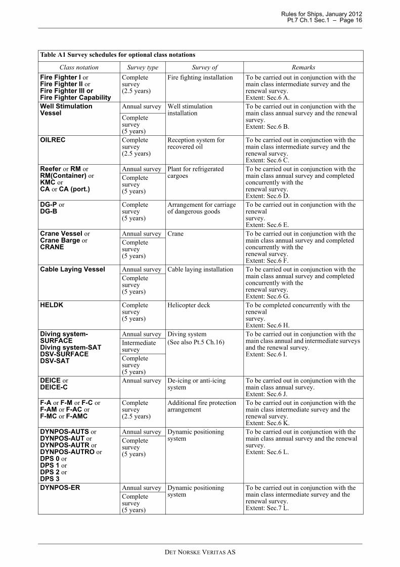
Table A1 Survey schedules for optional class notations
Class notation Survey type Survey of Remarks
Fire Fighter I orFire Fighter II orFire Fighter III orFire Fighter Capability
Complete survey (2.5 years)
Fire fighting installation To be carried out in conjunction with the main class intermediate survey and the renewal survey. Extent: Sec.6 A.
Well Stimulation Vessel
Annual survey Well stimulation installation
To be carried out in conjunction with the main class annual survey and the renewal survey. Extent: Sec.6 B.
Complete survey (5 years)
OILREC Complete survey (2.5 years)
Reception system for recovered oil
To be carried out in conjunction with the main class intermediate survey and the renewal survey. Extent: Sec.6 C.
Reefer or RM or RM(Container) or KMC or CA or CA (port.)
Annual survey Plant for refrigerated cargoes
To be carried out in conjunction with the main class annual survey and completed concurrently with the renewal survey. Extent: Sec.6 D.
Complete survey (5 years)
DG-P or DG-B
Complete survey (5 years)
Arrangement for carriage of dangerous goods
To be carried out in conjunction with the renewal survey. Extent: Sec.6 E.
Crane Vessel orCrane Barge or CRANE
Annual survey Crane To be carried out in conjunction with the main class annual survey and completed concurrently with the renewal survey. Extent: Sec.6 F.
Complete survey (5 years)
Cable Laying Vessel Annual survey Cable laying installation To be carried out in conjunction with the main class annual survey and completed concurrently with the renewal survey. Extent: Sec.6 G.
Complete survey (5 years)
HELDK Complete survey (5 years)
Helicopter deck To be completed concurrently with the renewal survey. Extent: Sec.6 H.
Diving system-SURFACEDiving system-SATDSV-SURFACEDSV-SAT
Annual survey Diving system(See also Pt.5 Ch.16)
To be carried out in conjunction with the main class annual and intermediate surveys and the renewal survey.Extent: Sec.6 I.
Intermediate surveyComplete survey (5 years)
DEICE or DEICE-C
Annual survey De-icing or anti-icing system
To be carried out in conjunction with the main class annual survey.Extent: Sec.6 J.
F-A or F-M or F-C or F-AM or F-AC or F-MC or F-AMC
Complete survey (2.5 years)
Additional fire protection arrangement
To be carried out in conjunction with the main class intermediate survey and the renewal survey.Extent: Sec.6 K.
DYNPOS-AUTS orDYNPOS-AUT orDYNPOS-AUTR or DYNPOS-AUTRO orDPS 0 or DPS 1 or DPS 2 or DPS 3
Annual survey Dynamic positioning system
To be carried out in conjunction with the main class annual survey and the renewal survey.Extent: Sec.6 L.
Complete survey (5 years)
DYNPOS-ER Annual survey Dynamic positioning system
To be carried out in conjunction with the main class intermediate survey and the renewal survey.Extent: Sec.7 L.
Complete survey (5 years)
DET NORSKE VERITAS AS

Rules for Ships, January 2012 Pt.7 Ch.1 Sec.1 – Page 17
NAUT-OC (previous notation W1-OC) or NAUT-AW (previous notation W1) orNAUT-OC-Q or NAUT-AW-Q or NAUT-OSV(A) or NAUT-OSV(T)
Annual survey Bridge design To be carried out in conjunction with the main class annual survey and the renewal survey.Extent: Sec.6 M.
Complete survey (5 years)
NAV-O Complete survey (5 years)
Bridge design on seagoing ships
To be carried out in conjunction with the statutory survey.Extent: Sec.6 M.
HMON(...) Annual survey Hull monitoring system To be carried out in conjunction with the main class annual survey.Extent: Sec.6 N.
VCS-1B or VCS-2B
Complete survey (5 years)
Vapour control system To be carried out in conjunction with the main class annual survey and the renewal survey.Extent: Sec.6 O.
CLEAN orCLEAN DESIGN
Annual survey Environment class To be carried out in conjunction with the main class annual survey.Extent: Sec.6 P.
TMON Annual survey Tailshaft monitoring To be carried out in conjunction with the main class annual survey.Extent: Sec.6 Q.
FUEL (...) Annual survey Fuel treatment and condition system
To be carried out in conjunction with the main class annual survey and the renewal survey.Extent: Sec.6 R.
Complete survey (5 years)
LCS-DC Annual survey Loading computers for damage control
To be carried out in conjunction with the main class annual survey.Extent: Sec.6 S.
RC-1 orRC-2 orRC-3
Complete survey (5 years)
Arrangement for carriage of refrigerated containers
To be carried out in conjunction with the renewal survey.Extent: Sec.6 T.
VIBR Complete survey (5 years)
Vibration class To be carried out in conjunction with the renewal survey.Extent: Sec.6 U.
BWM-E ( ) or BWM-EP ( ) or BWM-T
Annual survey Ballast water management To be carried out in conjunction with the main class annual survey.Extent: Sec.6 V.
AP-1(a%)(+) or AP-2(a%)(+) or AP-3(a%)(+)
Complete survey (2.5 years)
Alternative propulsion To be carried out in conjunction with the main class intermediate survey or the renewal survey.Extent: Sec.6 W.
WINTERIZED BASICWINTERIZED COLD (t1, t2)WINTERIZED ARCTIC (t1, t2)
Annual survey Winterized vessels To be carried out in conjunction with the main class annual survey.Extent: Sec.6 X.
Table A1 Survey schedules for optional class notations (Continued)
Class notation Survey type Survey of Remarks
DET NORSKE VERITAS AS

Rules for Ships, January 2012 Pt.7 Ch.1 Sec.1 – Page 18
E0 orECO
Annual survey Periodically unattended machinery space and Machinery centralised operation
To be carried out in conjunction with the main class annual survey.Extent: Sec.6 Y.
Complete survey (5 years)
Naval, or Naval Support (....)
Annual survey Arrangement, systems and equipment for naval ships
To be carried out in conjunction with the main class annual survey and the renewal survey.Extent: Sec.7 A.
Complete survey (5 years)
NAUTICUS(Operation)
None None Enhanced exchange of information between theowner and the Society, as part of the periodical survey schemes. Additional/separate surveys are not applicable.Extent: Sec.7 B.
SPS Annual survey Installed equipment, systems and features for special purpose ships carrying special personnel who are neither crew members nor passengers.
Generally covered by the main class survey.Extent: Sec.7 C.
EC Annual survey Equipment and construction for easy cleaning
To be carried out in conjunction with the main class annual survey.Extent: Sec.7 D.
EL-2 Annual survey Equipment and construction for easy loading
To be carried out in conjunction with the main class annual survey.Extent: Sec.7 D.
NAUT-NAVY Annual survey Naval ships To be carried out in conjunction with the main class annual survey.Extent: Sec.7 E.
NBC-1NBC-2
Annual survey Systems intended to protect naval surface vessels from nuclear, biological and chemical threats
To be carried out in conjunction with the main class annual or renewal survey. Extent: Sec.7 F.
Complete survey (5 years)
SILENT-ASILENT-SSILENT-FSILENT-RSILENT-E
Complete measurement survey (5 years)
Underwater noise level emission
To be carried out in conjunction with the renewal survey.Extent: Sec.7 G.
ESV-DP[HIL]ESV-TAM[HIL]
Annual survey HIL survey DP-control system
Refer to Sec.7 H.Complete survey
DP-control system HIL testing
Anchor HandlingTowingAHTSTug
Annual survey Anchor handling and towing equipment
To be carried out in conjunction with the main class annual survey.Extent: Sec.7 I.
SBM Annual audit Safety and environmental protection (SEP) management system
Intermediate audit applicable only after the company has been granted such status. The company may apply for intermediate audit after the first annual audit. When granted, the intermediate audit will replace the annual audit. See Ch.3 Sec.1 D402.
Intermediate audit Renewal audit
Table A1 Survey schedules for optional class notations (Continued)
Class notation Survey type Survey of Remarks
DET NORSKE VERITAS AS

Rules for Ships, January 2012 Pt.7 Ch.1 Sec.1 – Page 19
B. Hull and Equipment
B 100 Conditions for survey and access to structures
101 In preparation for survey and to allow for a thorough examination, all spaces and areas shall be cleanedincluding removal from surfaces of all loose accumulated corrosion scale. In tanks where soft coating has beenapplied, representative areas and those areas where it is obvious that further close-up examination is requiredshall be cleaned free of soft coating.
Guidance note:Spaces should be sufficiently clean and free from water, scale, dirt, oil residues etc. to reveal corrosion, deformation,fractures, damage, or other structural deterioration. However, those areas of structure whose renewal has already beendecided need only be cleaned and descaled to the extent necessary to determine the limits of the renewed areas. Formore detailed information with regard to a tank where soft coatings have been applied, see IACS RecommendationNo. 44.
---e-n-d---of---G-u-i-d-a-n-c-e---n-o-t-e---
102 Casings, ceilings or linings, and loose insulation, where fitted, shall be removed, as required by thesurveyor, for examination of plating and framing. Compositions on plating shall be examined and sounded, butneed not be disturbed if found adhering satisfactorily to the plating.In drydock or on a slipway, the ship shall be placed on blocks of sufficient height and with the necessary stagingto permit the examination of elements such as shell plating including bottom and bow plating, stern frame andrudder, sea chests and valves, propeller, etc. (IACS UR Z3.3.2.1)
Table A2 Class notations fully or partly covered by main class surveys
Class notation Survey of Remarks
Container Carrier or CONTAINER
Arrangement and equipment for carriage of container cargo
Covered by the renewal survey.
Car Carrier Arrangement and equipment for carriage of cars Covered by the main class annual survey.
MCDK Movable car deck arrangement Covered by the main class annual survey.
PET Arrangement for carriage of motor vehicles with fuel in their tanks
Covered by the main class annual survey.
INERT Inert gas plant Covered by the main class annual and renewal surveys.
PST Protected slop tank Covered by the main class annual survey. BOW LOADING Bow loading arrangement Covered by the main class annual survey. LFL or LFL* Arrangements for carriage of low flashpoint
liquidsCovered by the main class annual and renewal surveys.
Pusher or Pusher/Barge Unit
Arrangement for pushing and being pushed Covered by the renewal survey.
Reefer or RM or RM(Container) or KMC or CA or CA (port.)
Plant for refrigerated cargoes Partly covered by the main class annual survey.Extent not covered by main class surveys: Sec.6 D.
RO/RO Arrangement for roll on/ roll off cargo handling Covered by the main class annual survey. Tanker for Potable Water
Arrangement and equipment for carriage of potable water
Covered by the renewal survey.
CCO Centralised cargo control Covered by the renewal survey. VCS-1 or VCS-2 orVCS-3
Vapour control system Partly covered by the main class annual and renewal surveys. Extent not covered by main class surveys: Sec.6 O
GAS FUELLED Gas fuelled engine installation Covered by the main class annual and intermediate surveys, and the renewal survey.
FC-POWER orFC-SAFETY
Fuel cell installations Covered by the main class annual and intermediate surveys, and the renewal survey.
OPP-F Oil pollution prevention measures for fuel oil systems
Covered by the renewal survey.
DET NORSKE VERITAS AS
Rules for Ships, January 2012 Pt.7 Ch.1 Sec.1 – Page 20
103 All spaces shall be made safe for access, i.e. gas freed, ventilated and illuminated, and prepared for thesurveyor to examine the structure in a safe and practical way. One or more of the following means for access,acceptable to the surveyor, shall be provided:
— permanent staging and passages through structures— temporary staging and passages through structures— lifts and moveable platforms— hydraulic arm vehicles such as conventional cherry
pickers— boats or rafts— portable ladder— other equivalent means.
For close-up examination of the cargo hold shell frames of bulk carriers, the following additional requirementsapply:
a) boats or rafts may be accepted provided the structural capacity of the hold is sufficient to withstand staticloads at all levels of water
b) for bulk carriers less than 100 000 dwt:
— portable ladder for examination of lower section of a shell frame including bracket may be accepted,provided the ladder is not more than 5 m in length
c) for bulk carriers 100 000 dwt and above:
— portable ladder is not accepted— hydraulic arm vehicle such as conventional cherry picker is limited to examination of lower and middle
parts of hold frames at renewal survey no. 2 and subsequent intermediate and renewal surveys.
Notwithstanding the above requirements, the use of portable ladder fitted with a mechanical device to securethe upper end of the ladder is acceptable for the close-up examination of lower section of a shell frameincluding bracket required at annual surveys.
104 Rafts or boats alone may be allowed for survey of the under deck areas for tanks or spaces, if the depthof the webs is 1.5 m or less.If the depth of the webs is more than 1.5 m, rafts or boats alone may be allowed only:
a) when the coating of the under deck structure is in GOOD condition and there is no evidence of wastage orb) if a permanent means of access is provided in each bay to allow safe entry and exit. This means:
— access direct from the deck via a vertical ladder and a small platform fitted approximately 2 m belowthe deck in each bay or
— access to deck from a longitudinal permanent platform having ladders to deck in each end of the tank.The platform shall, for the full length of the tank, be arranged in level with, or above, the maximumwater level needed for rafting of under deck structure. For this purpose, the ullage corresponding to themaximum water level shall be assumed not more than 3 m from the deck plate measured at the midspanof deck transverses and in the middle length of the tank.
If neither of the above conditions are met, then staging or “other equivalent means” of access shall be providedfor the survey of the under deck areas.The use of rafts or boats alone does not preclude the use of boats or rafts to move about within a tank during asurvey.
Guidance note:Reference is made to IACS Recommendation No. 39 - Guidelines for the use of Boats or Rafts for Close-up surveys.
---e-n-d---of---G-u-i-d-a-n-c-e---n-o-t-e---
Guidance note:Use of remote inspection technique methods to facilitate the required internal examinations, including close-upexaminations and thickness measurements, may be specially considered by the Society. The methods applied shallprovide the information normally obtained from a survey carried out by the surveyor.In order to verify the results, confirmatory close-up examinations and thickness measurements at selected locationsshall be carried out by the surveyor, not using the remote inspection technique method.Proposals for use of remote inspection technique methods shall be submitted to the Society for acceptance in advanceof the survey.
---e-n-d---of---G-u-i-d-a-n-c-e---n-o-t-e---
105 Prior to commencement of any part of the renewal and intermediate survey, a survey planning meeting
DET NORSKE VERITAS AS
Rules for Ships, January 2012 Pt.7 Ch.1 Sec.1 – Page 21
shall be held between the attending surveyor(s), the master of the ship or an appropriately qualifiedrepresentative appointed by the master or the owner, and, as applicable, the owner's representative inattendance and the thickness measurement company operator, so as to ensure the safe and efficient conduct ofthe survey work to be carried out and, where applicable, for the purpose to ascertain that all the arrangementsenvisaged in the survey programme are in place.(IACS UR Z10.1, Z10.2, Z10.3, Z10.4, Z10.5)
B 200 Survey extent
201 The survey consists of examination, measurements and testing as required for different survey categorieswith the aim to ensure that the hull structure, hull equipment and piping are in satisfactory condition withrespect to corrosion, deformation, fractures, damage or other structural deterioration.
202 When examination or overall examination is required the structure or object is visually examined froma significant distance. In such cases the general maintenance, the condition of protective coating, rust deposits,leakages and structural detachments and damage may be observed and the surveyor may extend the survey asconsidered necessary.
203 When close-up examination is specified by the rules or required by the surveyor the structure or objectis visually examined from a distance normally within reach of hand.The surveyor may extend the close-up examination as deemed necessary taking into account the maintenanceof the spaces under survey, the condition of the corrosion prevention system and where spaces have structuralarrangements or details which have suffered defects in similar spaces or on similar ships according to availableinformation.Thickness measurements, for general assessment and recording of corrosion pattern, shall be taken of thosestructural members subject to close-up examination as specified by the requirements relevant for the survey oras given in 204.
204 The surveyor may require thickness measurements in any portion of the structure where signs of wastageare evident or in areas where wastage is normally found.The surveyor may extend the scope of the thickness measurements if considered necessary.
205 When thickness measurements are specified by the rules or required by the surveyor the measurementsshall be carried out to an extent sufficient to determine both general and local corrosion levels.Unless carried out by the surveyor himself, thickness measurements shall be carried out by a qualified companyapproved by the Society and witnessed by a surveyor. This requires the surveyor to be on board, while themeasurements are taken, to the extent necessary to control the process.Where it is required to carry out thickness measurements of structures subject to close-up examination, thesemeasurements shall be carried out simultaneously with the close-up examination.Thickness measurements carried out afloat may be accepted provided they are accompanied by a diving report.However, thickness measurements carried out from outside shall normally be limited to areas with restrictedaccess from inside. The diver shall be qualified in thickness measurement and the procedure confirmed on-site,as decided by the surveyor.For vessels which require dry docking as part of intermediate and/or renewal surveys, thickness measurementscarried out afloat will require confirmatory thickness measurements at time of dry docking as decided by thesurveyor.The surveyor shall review the final thickness measurement report and countersign the cover page.
206 Where substantial corrosion, as defined in A, is found, additional thickness measurements shall be takento confirm the extent of substantial corrosion.The additional measurements shall be taken in patterns corresponding to tables given in Sec.4 D, depending onship type.These additional thickness measurements shall be carried out before the survey is considered as completed.
207 The examination may be extended also in cases when:
— information is available of defects suffered on similar structure or details in similar tanks/holds or onsimilar ships
— the structure under survey has been approved with reduced scantlings due to an approved corrosion controlsystem.
B 300 Special consideration
301 For areas in spaces where hard protective coatings are found to be in GOOD condition, the extent ofclose-up examination and thickness measurements may be specially considered.Special consideration as used in this context is taken to mean, as a minimum, that sufficient close-up
DET NORSKE VERITAS AS
Rules for Ships, January 2012 Pt.7 Ch.1 Sec.1 – Page 22
examination and thickness measurements are carried out to confirm the actual average condition of thestructure under the protective coating.
B 400 Repair of structural damage or deterioration
401 A prompt and thorough repair as defined in A, shall be carried out of any damage in association withwastage over the allowable limits (including buckling, grooving, detachment or fracture), or extensive areas ofwastage over the allowable limits, which affects or, in the opinion of the surveyor, will affect the ship'sstructural, watertight or weathertight integrity. Areas to be considered include:
— bottom structure and bottom plating— side structure and side plating— deck structure and deck plating— inner bottom structure and inner bottom plating— watertight and oiltight bulkheads— inner side structure and inner side plating— hatch covers and hatch coamings— air pipes on the exposed decks including heads and weld connection between air pipes and deck plating— vent piping systems including ventilators and closing devices— bunker piping systems.
402 For locations where adequate repair facilities are not available, consideration may be given to allow theship to proceed directly to a repair facility. This may require discharging the cargo and or temporary repairs forthe intended voyage.
403 Additionally, when a survey results in the identification of corrosion or structural defects, either ofwhich, in the opinion of the surveyor, will impair the ship's fitness for continued service, remedial measuresshall be implemented before the ship continues in service.
404 Where the damage found on structure mentioned in item B401 is isolated and of a localized nature whichdoes not affect the ship's structural integrity, consideration may be given by the surveyor to allow anappropriate temporary repair to restore watertight or weather tight integrity and impose a Condition of Class,with a specific time limit.
B 500 Survey programme for ships subject to Enhanced Survey Programme (class notation ESP)
501 The owner in co-operation with the Society shall work out a specific survey programme prior to thecommencement of:
— any renewal survey— any intermediate survey for ships over 10 years of age.
The survey programme shall be in a written format. The survey shall not commence until the surveyprogramme has been agreed.The survey programme at intermediate survey may consist of the survey programme at the previous renewalsurvey supplemented by the executive hull summary of that survey and later relevant survey reports.The survey programme shall be worked out taking into account any amendments to the survey requirementsimplemented after the last renewal survey carried out.
502 The following documentation shall be collected and consulted with a view to selecting tanks, holds, areasand structural elements to be examined:
— survey status and basic ship information— documentation on board as described in 600— main structural plans, including information regarding use of high strength steel, stainless steel and clad
steel— inspections by the owner's personnel during the last 3 years with reference to structural deterioration in
general, leakages in tank boundaries and piping and condition of the coating and corrosion protection system,relevant previous survey or inspection reports from the Society and the owner
— cargo and ballast history for the last 3 years, typical cargoes and carriage of cargo under heated conditions— description and history of the coating and corrosion protection system, if any— information regarding the relevant maintenance level during operation including port state control reports
of inspection containing hull related deficiencies, Safety Management System non-conformities relating tohull maintenance, including the associated corrective action(s)
— information and other relevant data regarding conversion or modification of the ship's tanks and holds.
503 The submitted survey programme shall account for and comply with, as a minimum, the requirementsfor close-up examination, thickness measurements and tank testing as given for the relevant ship type.
DET NORSKE VERITAS AS

Rules for Ships, January 2012 Pt.7 Ch.1 Sec.1 – Page 23
504 The submitted survey programme is, in addition to the requirements given in 603, to include relevantinformation including at least:
— basic ship information and particulars— main structural plans including information on the use of high strength steel, stainless steel and clad steel— plan of tanks and holds— list of tanks and holds with information on use, corrosion prevention and condition of corrosion prevention— condition for survey such as cleaning of tanks and holds, gas freeing, ventilation, lighting, etc.— provisions and methods for access to structures— equipment for survey— nomination of tanks, holds and areas for close-up examination— nomination of sections for thickness measurements— nomination of tanks to be tested— damage experience related to the ship in question and, as applicable, for similar ships.
505 The extent of survey as described in the survey programme may be extended as found necessary by theSociety based on the results of the survey.
B 600 Documentation on board ships subject to Enhanced Survey Programme (class notation ESP)
601 The owner shall supply and maintain on board documentation as specified in 602 and 603. Thedocumentation shall be kept on board for the lifetime of the ship and shall be readily available for the surveyor.
602 A survey report file consisting of:
— reports of structural surveys— executive hull summary— thickness measurements reports— survey programme,
shall be available on board. The survey report file shall be available also in the owner's and the Society's offices.
603 The following additional documentation shall be available on board:
a) main structural plans of cargo and ballast holds or tanksb) previous repair historyc) cargo and ballast historyd) extent of use of inert gas plant and tank cleaning procedurese) records of inspections and actions by ship's personnel with reference to:
— structural deterioration in general— leakage in bulkheads and piping— condition of coating or corrosion prevention, if any— any other information that will help to identify critical structural areas and/or suspect areas requiring
inspection.
C. Machinery and Systems
C 100 Maintenance and preparation for survey
101 Every ship shall have implemented a maintenance system. The maintenance system shall ensure that:
— inspections and maintenance are carried out at defined intervals— any non-conformity is reported with its possible cause, if known— appropriate corrective action is taken— records of these activities are maintained.
The machinery and systems subject to class shall be maintained in accordance with the maintenance systemimplemented. For machinery components to be included, see Sec.4 Table E1.
102 In preparation for survey and to allow for a thorough examination, machinery components and relatedspaces shall be cleaned, including removal from surfaces of loose accumulated corrosion scale, mud and oil-residues. The spaces and components of attention shall have proper access including dismantling as necessary.
C 200 Shaft alignment
201 For propulsion systems where shaft alignment calculations have been required, the alignment shall beconfirmed by suitable measurements when the system has been dismantled and or when external forces (e.g.grounding, welding work) may have influenced the alignment.
DET NORSKE VERITAS AS
Rules for Ships, January 2012 Pt.7 Ch.1 Sec.1 – Page 24
The measurements shall be carried out with the ship afloat and be presented to the surveyorSystems which require shaft alignment are specified in Pt.4 Ch.4 Sec.1 A403, F400.
C 300 Replacement of machinery components
301 When machinery components are renewed, such components should in general be delivered inaccordance with requirements as per valid rules at the time of newbuilding.
Guidance note:
1) If the relevant rule requires an NV certificate for the actual part, then the design and the survey, as relevant, shouldbe in accordance with the applicable rule requirement.Applicable for diesel engines: The actual part should be produced by a manufacturer authorised by the enginedesigner or the designer's licensee.
2) If the relevant rule requires a Work certificate for the actual part:
- when design approval is required, the certificate should confirm compliance with the relevant parts (e.g. NDT,material, dimensions, etc.) of the approved drawings and specifications
- when no design approval is required (i.e. drawings and specifications submitted for information only), the requiredcertificate should confirm compliance with the applicable rule requirements (e.g. pressure testing, NDT, etc.).
---e-n-d---of---G-u-i-d-a-n-c-e---n-o-t-e---
Applicable for diesel engines: If the part is produced by a manufacturer not authorised by the engine designeror the designer's licensee, the Society may carry out inspections according to Pt.4 Ch.3 Sec.1 Table C1 andissue a report confirming this. However, this inspection report will not cover design approval and testing as apart of the engine. It is the operator's responsibility to evaluate and take the necessary precautions to see thatthe parts are fit for their intended use.
C 400 Machinery verification
401 If significant repairs are carried out to main or auxiliary machinery, or steering gear, a dock and/or seatrial shall be carried out as required by the attending surveyor.
C 500 Gas turbine installations
501 The society accepts that complete gas turbine units, or modules, are taken ashore for complete overhaulby. original engine manufacturer (OEM) or OEM approved company. It is the responsibility of the owner toinvolve the Society in the overhaul work at the OEM or OEM approved company.
502 Complete replacement turbines shall be certified. The company performing the work shall be either theOEM, or OEM-approved. Attendance of surveyor during overhaul as considered necessary.Sea trial/ installation test to be performed to the attending surveyor's satisfaction.
503 Documented history regarding maintenance scope, and it’s relevance to running hours and preservationduring storage for the unit installed shall be available for examination.
504 Maintenance of gas turbine rotating components, or components in the gas path, shall be carried outusing only original spare parts, or spare parts accepted by the OEM.
505 Maintenance carried out in the form of module replacement (e.g. hot section change-out), shall utilisereplacement modules that are of identical design and construction, and either possess the appropriatecertification by the Society (i.e. originate in another engine certified by the Society used for a similarapplication), or are new and produced in accordance with type approved design and under a validmanufacturing survey arrangement (MSA). Modules with other origins will normally not be accepted.
C 600 Boiler installations
601 For all vessels with boilers, the boiler water quality shall be maintained to the standard required by theequipment manufacturer.
602 The boiler water shall be monitored/ tested at least once in every 24 hours daily for main boilers and atleast every 48 hours for auxiliary boilers.
603 Records of boiler water management shall be available onboard containing the following parameters:
— water consumption— chemicals consumption— chloride content— phosphate and oxygen measuring parameters— pH value— frequency and duration of “surface scumming” (if fitted) and bottom “blow downs” — conductivity when included in the water treatment program utilised.
DET NORSKE VERITAS AS
Rules for Ships, January 2012 Pt.7 Ch.1 Sec.1 – Page 25
604 Procedures for boiler water management for boilers temporarily out of service shall be in place. Theboiler shall be placed in either dry or wet condition when out of service for a prolonged period of time (Fullvoyage, ship idle in port, ship laid-up).
C 700 Survey of special components
701 Components or elements of the propulsion system, such as:
— vibration dampers— elastic couplings— speed governor or quick passing through device.
which may change characteristics during the lifetime and hence influence the torsional behaviour of the system,shall be maintained and inspected as approved by the Society or as recommended by the manufacturer.As an alternative to opening up for inspection, measurements may be carried out to confirm the correct dynamicconditions. The torsional vibration measurements shall be carried out and reported to the Society. The resultsshall be compared with the approved limits (torsional vibration calculations).If an elastic coupling is replaced by another type, new torsional vibration calculations shall be submitted forapproval.
DET NORSKE VERITAS AS

Rules for Ships, January 2012 Pt.7 Ch.1 Sec.2 – Page 26
SECTION 2 ANNUAL SURVEYS EXTENT – MAIN CLASS
A. General Requirements
A 100 General
101 Annual survey is a general survey of the hull and equipment, machinery and systems to confirm that theship complies with the relevant rule requirements and is in satisfactorily maintained condition.
102 For chemical tankers and liquefied gas tankers the annual survey of components and systems for cargohandling and cargo containment is preferably to be carried out during a loading or discharging operation.Access to cargo tanks or inerted hold spaces, necessitating gas-freeing/aerating will normally not be required.
A 200 Review of documentation, operational instruments, signboards and markings
201 If a loading instrument or loading computer system is available onboard it shall be verified that thesystem has a valid certificate.It shall be documented that an annual check of the loading instrument/computer by running one of the testconditions has been carried out. If not, the surveyor shall verify the running of the test condition onboard.
202 Approved loading and stability information shall be verified available onboard.This information shall be the same as required when the ship was assigned class with the Society or at a laterconversion of the ship, in accordance with the rule requirements applicable in each case.
203 Manual with instructions for operation and/ or maintenance shall be verified for:
— doors in ship's bow (outer and inner), sides and stern— combination ships— inert gas system— oil discharge monitoring system— crude oil washing system— vapour emission control system— protected slop tanks in combination ships, (including ships with class notation PST)— offshore bow loading arrangement, (including ships with class notation BOW LOADING)— liquefied gas tankers— arrangement for carriage of low flashpoint liquids, (including ships with class notation LFL)— gas fuelled engine installations, (including ships with class notation GAS FUELLED)— fuel cell installations (including ships with class notation FC-POWER or FC-SAFETY).
204 List of required signboards or notice plates shall be verified for:
— doors in ship's bow (outer and inner), sides and stern— steering gear operating instruction posters, on the bridge and in the steering gear compartment— carriage of motor vehicles with fuel in their tanks in enclosed spaces, (including ships with class notation
PET)— combination ships— protected slop tanks in combination ships, (including ships with class notation PST)— liquefied gas tankers— arrangement for carriage of low flashpoint liquids, (including ships with class notation LFL)— gas fuelled engine installations, (including ships with class notation GAS FUELLED)— fuel cell installations (including ships with class notation FC-POWER or FC-SAFETY).
205 It shall be verified that records of inspections and maintenance in accordance with the implementedmaintenance system for machinery are kept available onboard.
206 For ships which have been granted alternative survey arrangement(s) the following apply:For survey arrangement Hull Continuous or Machinery Continuous, satisfactory completion of survey itemsdue in the previous period shall be verified.For survey arrangement Hull PMS, Machinery PMS or Machinery CM the documentation of the approvedsystem shall be reviewed and evaluated.This implies that the following shall be verified:
— satisfactory performance— continuation of the conditions and acceptance criteria for the approval— assessment of handling onboard
DET NORSKE VERITAS AS

Rules for Ships, January 2012 Pt.7 Ch.1 Sec.2 – Page 27
— satisfactory completion of records of the required inspections and maintenance over the previous period,including description of corrective actions taken in response of occurred deficiencies.
If found necessary by the surveyor, examination and testing, including opening of machinery, may be required.Based on a satisfactory result, the validity of the survey arrangement will be extended until the next annualsurvey.
207 For ships with class notation ESP, the surveyor shall examine the documentation onboard as specifiedin Sec.1 B600, and its contents as a basis for the hull survey.
208 For liquefied gas tankers the survey shall include:
— examination of the log books with regard to the condition of the cargo containment and the correctfunctioning of the cargo handling systems. The running hours per day of the reliquefaction plants or theboil-off rate and the inert gas consumption shall be considered in order to check that no irregularities inperformance have occurred
— verification of instruction and information material such as cargo handling plans, cargo instrumentationmaintenance manual, filling limit information, cooling down procedures etc. as being onboard.
209 For ships that shall comply with SOLAS Reg. IX/2, irrespective of the issuing authority for the SafetyManagement Certificate (SMC), the surveyor will complete a list of evidence of possible safety managementsystem failures recorded on the occasion of the annual survey. The list will be submitted with the annual surveyreport.
B. Hull and Equipment
B 100 General - all ships
101 The survey shall cover examination of:
a) weather decks and ship side plating above water lineb) anchoring equipment, see 102c) openings and closing appliances for cargo holds or tanks:
— hatch covers and coamings on exposed weatherdecks, see 103— cargo tank openings, see 105
d) other openings and closing appliances:
— doors in ship's bow, sides and stern, see 104— ventilator and air pipes, see 105— watertight doors and penetrations in watertight bulkheads— exposed machinery casing and skylights— ventilation ducts for engine and boiler rooms— windows, deadlights and side scuttles.
e) scuppers, discharges and valves with hull attachmentsf) freeing ports and shuttersg) fittings and hull supporting structures, as far as practicable, for stowage, securing and supporting of:
— timber deck cargoes— containers— movable car deck pontoons
h) piping arrangements on deck, see 105i) means of protection of crew, such as guard rails, bulwark, gangways and lifelinesj) towing and mooring equipment, see 106k) emergency towing arrangements, see 107l) spaces:
— ballast tanks, see 108— suspect areas, see 109— thickness measurements taken or extended when substantial corrosion recorded or found, see 110— fire doors and fire dampers in ventilation ducts— means of escape, see 111
DET NORSKE VERITAS AS

Rules for Ships, January 2012 Pt.7 Ch.1 Sec.2 – Page 28
m) special installations:
— plants for refrigerated cargoes, see 112— inert gas plants, see 105
n) verification of electrical bonding to the hull of pipelines and independent tanks, as applicable.
102 For the anchoring equipment the survey shall include examination of windlasses, brakes, securing andchain stoppers, with special attention to condition and wear of brake linings.Function test may be required if deemed necessary by the surveyor.
103 For hatch covers and coamings the survey shall include:
a) examination of mechanically operated steel coversb) examination of portable steel pontoons, portable wooden covers and portable beamsc) examination of hatch coaming plating and their stiffenersd) examination of closing, sealing and securing devicese) testing at random of the operation of mechanically operated hatch covers including:
— stowage and securing in open condition— proper fit and efficiency of sealing in closed condition— hydraulic and power components, wires, chains and link drives.
Confirmation shall be obtained that no unapproved changes have been made to the hatch covers, hatchcoamings and their securing and sealing devices since the last survey.
104 For doors in ship's bow (outer and inner), sides and stern, the survey shall include:
a) examination of:
— structural arrangement of doors, ramps and hinging arms— shell structure surrounding door openings— hinges with bearings, thrust bearings (side-hinged doors), sealing arrangement, drainage arrangement,
electrical equipment and hydraulic system for opening and closing of doors and operation of cleats,supports and locking devices
— close-up examination of cleats, support and locking devices— space between outer and inner bow doors.
b) testing of the operation of doors during a complete opening and closing operation.Non-destructive testing and thickness measurements may be required. Clearances of hinges, closingdevices, bearings and thrust bearings shall be measured, where no dismantling is required. Where thefunction test is not satisfactory, dismantling may be required to measure the clearances, in such casesexamination of hinge pins and bearings together with NDT of the hinge pins shall be carried out.
c) testing of indicators and audible alarms including mode selection function “harbour/sea voyage”.Guidance note:The indicator system shall show by visual indication if any of the doors are not fully closed and not fully locked, andby audible alarms if securing devices become open or locking devices become unsecured.
---e-n-d---of---G-u-i-d-a-n-c-e---n-o-t-e---
Verification of fail-to-safe performance for indicator and alarm systems on the navigation bridge. Sensors shall be examined for proper condition and protection from water, ice formation and mechanicaldamage.
d) testing of television surveillance systems.e) testing of water leakage detection system.f) testing for effectiveness of sealing arrangement by hose testing or equivalent.
Guidance note:If the visual examination and function test have shown satisfactory results, testing of side and stern doors on cargoships need not be carried out unless considered necessary by the surveyor.
---e-n-d---of---G-u-i-d-a-n-c-e---n-o-t-e---
g) testing of drainage system for the space between the bow door and ramp, or where no ramp is fitted,between the bow door and inner door.
In cases where the examination of doors has been carried out by a company approved by the Society, the extentof survey may be limited at the discretion of the surveyor. However, the survey shall, as a minimum, include:
DET NORSKE VERITAS AS
Rules for Ships, January 2012 Pt.7 Ch.1 Sec.2 – Page 29
— examination of structural arrangement of doors including surrounding structures and space between outerand inner bow doors
— testing of complete opening and closing operation.
105 All piping on deck shall be overall examined.Special attention shall be paid to:
— ventilators and air pipes with coamings and closing appliances— weld connection between air pipes and deck plating and to air pipe heads installed on the exposed deck— flame screens on vents to all bunker tanks.
Pressure testing and thickness measurements of any piping system may be required if found necessary by thesurveyor.For tankers the survey shall include examination of:
— cargo tank openings with pressure/ vacuum valves— venting/ gas freeing arrangements including masts and risers with flame screens/ flame arrestors— provisions for drainage of cargo tank vent lines.
For gas tankers the survey shall include verification of:
— sealing of cargo tank relief valves. The certificate with relief valves' opening and closing pressures shall beconfirmed to be onboard.
For ships with inert gas plant (including ships with class notation INERT), the inert gas piping shall beexamined with special attention to gas or effluent leakage.For ships with bow loading arrangement (including ships with class notation BOW LOADING), theexamination shall include inert gas purge pipes.For ships with gas detection system, the examination shall include verification of integrity of the suction linesbetween suction points and analysing units.
106 The towing and mooring equipment shall be verified properly marked with any restriction associatedwith its safe operation.
Guidance note:Applicable to ships of 500 GT and above, the keels of which are laid on or after 1 January 2007.
---e-n-d---of---G-u-i-d-a-n-c-e---n-o-t-e---
107 Emergency towing arrangements shall be examined as far as practicable. Aft towing arrangement shallbe confirmed as pre-rigged and forward chafing gear shall be confirmed as stowed in such a way that it can berapidly connected to the strongpoint. Where light is provided on pick-up gear marker buoy, proper functioningshall be confirmed.
Guidance note:Emergency towing arrangements are required on oil tankers, chemical tankers and gas carriers of 20 000 tonnesdeadweight and above in accordance with IMO resolution MSC.35(63)
---e-n-d---of---G-u-i-d-a-n-c-e---n-o-t-e---
108 Ballast tanks recorded for annual examination at previous survey, shall be overall examined.Close-up examination including thickness measurements shall be carried out for areas with general breakdownof the protective coating, where extensive corrosion exists, and otherwise as found necessary by the surveyor.
109 Suspect areas recorded for annual examination at previous survey shall be close-up examined.
110 Areas recorded for annual examination as a consequence of substantial corrosion found at previoussurvey, or where substantial corrosion is found at the survey being carried out, shall have thicknessmeasurements taken or extended.The following tables shall be used:
Areas found with substantial corrosion, which are not repaired and have not been previously identified, shallbe recorded for thickness measurements at subsequent annual surveys.
Sec.4 Table D1.2 in general as guidance,Sec.4 Table D3.3 for single skin bulk carriers,Sec.4 Table D4.3 for double skin bulk carriers,Sec.4 Table D5.3 for single hull oil tankers and single hull chemical tankers,Sec.4 Table D6.3 for double hull oil tankers and double hull chemical tankers.
DET NORSKE VERITAS AS

Rules for Ships, January 2012 Pt.7 Ch.1 Sec.2 – Page 30
Note: This requirement is not applicable to cargo tanks of oil and chemical tankers.
111 Means of escape from passenger and crew spaces to lifeboat embarkation deck shall be verified in orderand according to the as built plans.Crew spaces include restricted spaces such as engine room, boiler room, shaft tunnel and Ro-Ro cargo spaces.For ships with bow loading arrangement (including ships with class notation BOW LOADING), emergencyescape routes from bow control station shall be verified in order.
112 For ships with plant for refrigerated cargoes (including ships with class notation Reefer or RM orRM(Container) or KMC or CA or CA (port.)), the survey shall include examination of:
— ducts, hatches and doors with regard to escape possibilities and prevention of personnel being trappedwithin chambers, air cooler rooms etc.
— the chambers with attention on internal lining and that the chambers are free from odour— scuppers, bilges with rose boxes, and piping (suction, sounding and drain) together with drip pans.
113 For ships with class notation MCDK, the survey shall include:
— examination of pontoon conditions— examination of supporting fittings and suspension / pillars— examination of lifting arrangement (wires, sheaves etc. if applicable)— examination of stowing arrangements in cargo hold— examination of pontoon racks on deck including lashing arrangements— examination of drainage arrangements in pontoon stowage areas— testing at random of movable car deck hoisting arrangement.
B 200 General dry cargo ships subject to Extended Hull Survey Requirements (EHSR) – additional requirements
201 For hatch covers and coamings the survey shall include:
— close-up examination of hatch coaming plating and their stiffeners— close-up examination of hatch cover plating where mechanically operated steel hatch covers are fitted
202 For ships 10 to 15 years of age the survey shall include overall examination of one forward and one aftcargo hold and their associated 'tween deck spaces.
203 For ships over 15 years of age the survey shall include:
— overall examination of all cargo holds and 'tween deck spaces— close-up examination in a forward cargo hold and one other selected cargo hold, of approximately lower 1/
3 length of the side frames, including the frame end attachment and the adjacent shell plating to a sufficientextent, minimum 25% of frames
— all piping and penetrations in cargo holds, including over-board piping.
Where the close-up examination reveals need for remedial measures, the survey shall be extended to includeclose-up examination of all side frames and adjacent shell plating of the relevant cargo holds and associated'tween deck spaces, as well as close-up examination of sufficient extent of all remaining cargo holds and 'tweendeck spaces.
B 300 Dry bulk cargo ships subject to Enhanced Survey Programme (class notation ESP) – additional requirements
301 For hatch covers and coamings the survey shall include:
— close-up examination of hatch coaming plating with panel stiffeners and brackets— close-up examination of hatch cover plating and stiffener attachments that may be accessible in the open
position where mechanically operated steel hatch covers are fitted— close-up examination of removable hatch cover steel pontoon plating.
302 For mechanically operated hatch covers, hatch cover sets which are wholly or partly within the forward25% of the ship's length and at least one additional set shall be surveyed open, closed and in operation to thefull extent on each direction, such that all sets on the ship are surveyed at least once in every 5-year periodincluding:
— stowage and securing in open condition— proper fit and efficiency of sealing in closed condition— operational testing of hydraulic and power components, wires, chains and link drives— examination of the fastening of all peripheral and cross joint cleats or other securing devices in closed
condition.
DET NORSKE VERITAS AS
Rules for Ships, January 2012 Pt.7 Ch.1 Sec.2 – Page 31
If there are indications of difficulty in operating and securing hatch covers, additional sets shall be tested inoperation as deemed necessary by the surveyor.
303 For single skin bulk carriers over 10 years of age the survey shall include:
— overall examination of all cargo holds— close-up examination in the forward cargo hold, of approximately lower 1/3 length of the side frames,
including the frame end attachment and the adjacent shell plating to a sufficient extent, minimum 25% offrames
— examination of all piping and penetrations in cargo holds, including overboard piping.
304 For single skin bulk carriers over 15 years of age, in addition to the requirements in 303, the survey shallinclude:
— close-up examination of one other selected cargo hold to the same extent as required for the forward cargohold
305 Where the close-up examination required in 303 and 304 reveals need for remedial measures, the surveyshall be extended to include close-up examination of all side frames and adjacent shell plating of the relevant cargohold, as well as close-up examination of sufficient extent of all remaining cargo holds.
306 For double skin bulk carriers 10 to 15 years of age the survey shall include:
— overall examination of two selected cargo holds— examination of all piping and penetrations in selected cargo holds, including overboard piping.
307 For double skin bulk carriers over 15 years of age the survey shall include:
— overall examination of all cargo holds— examination of all piping and penetrations in cargo holds, including overboard piping.
308 For single skin bulk carriers built with an insufficient number of transverse watertight bulkheads tosatisfy the requirements for damage stability as given in Ch.2 Sec.1 C the survey in the forward cargo hold shallbe extended as follows:For ships exceeding 10 years of age:
— close-up examination of the side frames, including the frame upper and lower end attachments and theadjacent shell plating to a sufficient extent, minimum 25% of frames
— where the close-up examination reveals need for remedial measures, the survey shall be extended to includeclose-up examination of all side frames and adjacent shell plating
For ships exceeding 15 years of age the survey shall be extended to include close-up examination of all sideframes and adjacent shell plating of the forward cargo hold.Thickness measurements shall be carried out to an extent sufficient to determine both general and localcorrosion levels at areas subject to close-up examination.The thickness measurements may be dispensed with provided the surveyor is satisfied by the close-upexamination that there is no structural diminution and the protective coating where fitted remains effective.
B 400 Oil and chemical tankers subject to Enhanced Survey Programme (class notation ESP) – additional requirements
401 Wheelhouse doors and windows, side scuttles and windows in superstructure and deckhouse bulkheadsfacing the cargo area and possible bow or stern loading and unloading arrangements shall be examined for gasand vapour tightness.
402 Segregation between cargo and segregated ballast system shall be confirmed.For chemical tankers, removable pipe lengths or other approved equipment necessary for cargo segregationshall be overall examined.
403 Pump rooms shall be examined with special attention to:
— piping with pumps— bulkheads for signs of oil leakage or fractures and, in particular, the sealing arrangements of all
penetrations of cargo pump room bulkheads— access ladders.
404 For combination ships with protected slop tanks, (including ships with class notation PST), thefollowing shall be examined:
— closing arrangement for hatches and other slop tank openings
DET NORSKE VERITAS AS
Rules for Ships, January 2012 Pt.7 Ch.1 Sec.2 – Page 32
— blanking arrangement for slop tank pipes.
B 500 Liquefied gas tankers – additional requirements
501 The cargo handling piping and cargo process piping, shall be examined, with special attention toinsulation on piping.
502 The sealing arrangements for tanks or tank domes penetrating decks or tank covers shall be examined.
503 Portable and or fixed drip trays or insulation for deck protection in the event of cargo leakage shall beexamined.
504 Wheelhouse doors and windows, side scuttles and windows in superstructure and deckhouse bulkheadsfacing the cargo area and possible bow or stern loading and unloading arrangements shall be examined for gasand vapour tightness.The closing devices for all air intakes and openings into accommodation spaces, service spaces, machineryarea, control stations and approved openings in superstructures and deckhouses facing the cargo area or bowand stern loading/unloading arrangements, shall be examined.
505 Gastight bulkheads with possible shaft sealing shall be examined.
506 Correct functioning of any arrangements for heating of structural hull steel shall be verified. Access tothe heated cofferdams etc. is normally not required.
C. Machinery and Systems
C 100 General - all ships
101 The survey shall cover:
a) examination of spaces, see 102b) external examination of boilers steam drums and steam generators, see 107c) external examination of pressure vesselsd) verification of integrity/ function of:
— jacketed high pressure fuel injection piping system— shielding of flammable oil piping system— insulation of hot surfaces exceeding 220ºC— oil burning equipment on boilers, hot water heaters, incinerators and inert gas generators.
e) steering gear, see 103f) fire extinguishing systems, see 104g) electrical installations, see 105h) gas fuelled engine and boiler installations, see 115i) fuel cell installations, see 116j) gas turbines, see 117k) examination of remote operation for quick closing/stop of fuel-valves, fuel/transfer-pumps and ventilation
fans. Spot testing of functions to be carried outl) examination of bilge systems, bilge level alarms and remote operationm) testing of communication systems from bridge to machinery and steering gear spacesn) equipment and systems related to carriage of special cargoes:
— refrigerated cargo, see 111— inert gas plants, see 112— protected slop tanks, see 113— volatile organic compound (VOC) recovery plants— low flashpoint liquids, see 114— motor vehicles with fuel in their tanks, see 118— examination of cargo systems in ships intended for supply service to offshore installations— examination and tightness testing of cement and dry mud cargo piping situated within the engine room
o) control and monitoring system of main and auxiliary machinery including boilers, thermal oil heaters, oilburning equipment and equipment for periodically unattended machinery space and machinery centralisedoperated, see 109
DET NORSKE VERITAS AS

Rules for Ships, January 2012 Pt.7 Ch.1 Sec.2 – Page 33
p) emergency systems for passenger ships, see 110.q) water ingress detection system and their alarms, for ships with single cargo hold and for bulk carriers, see
119.r) the control and means for draining and ballast pumping forward of the collision bulkhead, for bulk carriers,
see 119.
102 Machinery area and spaces in the cargo area entered in connection with cargo handling shall be examinedwith respect to general cleanliness and maintenance and with special attention to the fire and explosion hazardsin general.
103 For the main and auxiliary steering system the survey shall include:
— external examination of the steering gear arrangement and hydraulic piping and handrails, non-slip surfacesand oil storage tank with piping
— examination of oil filters (to be opened up for inspection)— test of power units and rudder actuators, or actuating system for azimuth gears— test of alarms— test of all modes of local and remote steering control systems for main and auxiliary steering gears
including rudder angle indicating systems communication between bridge and steering gear compartment— test of emergency steering control— verification of relaying heading information (compass readings)— test of alternative power supply, if required for vessel.
104 For fire extinguishing systems the survey shall include:
— testing of the water fire fighting system i.e. fire pumps, fire mains, hydrants and hoses as deemed necessary— verification of the international shore connection— verification of the non-portable and portable fire extinguishers and portable foam applicators— examination of the fireman's outfit— examination of the fixed fire extinguishing systems.
For ships with valid SOLAS Passenger Ship Safety Certificate or Cargo Ship Safety Equipment Certificates,the above tests may be reduced or omitted.
105 For electrical installations the survey shall include:
— examination of main source of electrical power with respect to general condition, fire hazard and personnelsafety, i.e. generators, main switchboards, distribution boards, control gear, consumers, chargers andbattery/UPS systems
— test of automatic start and connection to the switchboard of the stand-by generator set by initiating shut-down of the running diesel generator causing black-out. During this test, the emergency generator shall bedisabled. The test is applicable for all E0 vessels (built at any time) and all vessels constructed on or after1 July 1998, where electricity is necessary for propulsion and steering
— inspection of insulation monitoring devices for all distribution systems. If in doubt of correct reading (ex.if the reading is infinity), the device shall be tested
— examination of cable installations with respect to general condition, support and physical protection— examination of emergency source of electrical power with respect to general condition, fire hazard,
personnel safety and function, i.e. generator, emergency switchboard, emergency distribution boards,control gear, chargers, emergency consumers and battery/ UPS systems
— check if any modifications are done in the electrical system— test of emergency power system, i.e. manual and automatic connection of generator/batteries to emergency
switchboards, alternative start methods— examination of cables and equipment in gas dangerous spaces and zones with respect to general condition
and spark/explosion hazard.
106 The following surveys shall be carried out in conjunction with the renewal survey:
— Boiler survey (boilers, superheaters, economizers and air Preheaters or steam heated steam generators) seeSec.5 F.
107 Boilers, steam drums and steam generators are subject to an external examination, where the followingwill be assessed by a DNV surveyor:
— installation free of leakages (Steam/water/exhaust gases) — operational test of safety valve by use of the relieving gear — testing of safety and protective devices — functioning of soot blowing arrangements (if fitted) — monitoring / testing of the boiler water carried out at least once in every 24 hours daily for main boilers and
at least every 48 hours for auxiliary boilers
DET NORSKE VERITAS AS

Rules for Ships, January 2012 Pt.7 Ch.1 Sec.2 – Page 34
— boiler water quality maintained to the standard required by the equipment manufacturer / the supplier of theboiler water treatment programme in use
— procedures for boiler water management for boilers temporarily out of service in place. Boiler to be placedin either dry or wet lay-up when out of service for a prolonged period of time (Full voyage, ship idle in port,ships laid-up).
For exhaust gas heated economizers, verification of function of the safety valves may be carried out by theChief Engineer at sea. This test shall be recorded in the log book prior to survey for review by the attendingsurveyor.
108 Thermal oil installations are subject to an external examination, where the following will be assessed bya DNV surveyor:
— installation free of leakage— functioning of temperature control arrangement— integrity of mounted fire extinguishing system— no blockage in fire extinguishing / drenching water drainage— low flow alarm and emergency stop functions in order— thermal oil analysis not older than 3 months available.
If the laboratory analysis reveals, either:
— chemical degrading of oil in circulation— contamination by low flashpoint petrochemical products— contamination by carbon particles,
corrective measures shall be initiated by owner and subsequently assessed by a DNV surveyor.
109 The survey shall cover control and monitoring systems for main and auxiliary machinery including:
— propulsion machinery — electric power generation and distribution— steam generation— thermal oil heating— oil or gas burning equipment on incinerators, inert gas generators and hot water heaters.
The survey shall include
— emergency lighting in engine room— communication systems— fire alarm and fire protection systems.
For all systems, the survey shall include inspection of the installation with regard to electrical and mechanicalcondition, labels, signboards etc.For control and monitoring systems, the survey shall include:
— alarm functions— safety functions— remote control functions— automatic control functions— control panels and local indicating instruments— verification of change handling process for control and monitoring systems, see Table C2.
For ships with notation E0 or ECO, refer to Sec.6 Y.
110 For passenger ships the arrangement for emergency and transitional source of power shall be tested.
111 For ships with reefer plant or controlled atmosphere installations (including ships with class notationReefer or RM or RM(Container) or KMC or CA or CA (port.)), the survey shall include:
— examination of system for tightness— examination of the safety measures such as:— gas tight machinery room bulkheads— separate ventilation system— catastrophe ventilation or sprinkler arrangement— escape arrangements for process areas and continuously manned cargo chambers— protection of fans and other rotating machinery— alarms and emergency stop buttons— refrigerant leakage detectors— tests of electrical installation's insulation resistance to the extent found necessary by the surveyor.
DET NORSKE VERITAS AS
Rules for Ships, January 2012 Pt.7 Ch.1 Sec.2 – Page 35
112 For ships with inert gas plant (including ships with class notation INERT), the survey shall include:
— examination of blowers, scrubber, deck water seal, closed ullage system, pressure/vacuum monitoringsystem, P/V breaker and non-return valves
— testing of remotely operated or automatically controlled valves, interlocking features of soot blowers,alarms and safety devices as deemed necessary
— examination/testing of oil burning equipment, automation, instrumentation and safety functions on inertgas generator.
113 For combination ships with protected slop tanks, (including ships with class notation PST), thefollowing shall be examined:
— gas detection arrangement in cofferdams— oxygen control equipment.
114 For ships arranged for carriage of low flash point liquids (including ships with class notation LFL orLFL*), the survey shall include:
— examination of pumping and piping systems (cargo, heating, bilge)— examination of ventilation system— testing of emergency stop of pumps— testing of quick release of transfer hose— testing of tank high level alarms— examination of portable hydrocarbon gas-measuring apparatus— examination of portable oxygen-measuring apparatus, if applicable— examination of gas detection system in cofferdams, if applicable.— measurement of insulation resistance of electrical cables in the cargo area. The measurements may be
omitted provided a record of testing is available showing that measurements have been taken during thelast 12 months and that the results are satisfactory.
115 For ships with gas fuelled engine installations, (including ships with class notation GAS FUELLED),the survey shall include:
— external examination and function testing of remote operated valves in the gas piping system— external examination of gas pipe ducts— testing of instrumentation— testing of emergency shutdown system, as a minimum by:— releasing gas detectors and fire detectors— checking electrical disconnection in ESD protected engine rooms— checking safety functions in connection with the ventilation systems in gas engine rooms— verification of the functioning of ventilation systems— examination of drip trays in bunker station.
116 For ships with class notation FC-POWER or FC-SAFETY the survey shall include:
— external examination and function testing of remote operated valves in the FC fuel piping system— external examination of FC fuel pipe ducts— testing of instrumentation— testing of safety system, as a minimum by:
- releasing gas detectors and fire detectors- checking safety functions in connection with the ventilation systems in FC fuel spaces
— verification of the functioning of ventilation systems— examination of drip trays in bunker station.
117 For ships with gas turbines the survey shall include the extent and criteria specified in Table C1.
DET NORSKE VERITAS AS

Rules for Ships, January 2012 Pt.7 Ch.1 Sec.2 – Page 36
The survey items may be covered through inspection or overhaul at a service or maintenance centre providedthe requirements given in Sec.1 C500 are adhered to.
118 For ships carrying motor vehicles with fuel in their tanks in enclosed spaces (including ships with classnotation Car Carrier or PET), the survey shall include:
— examination of automatic fire alarm system in cargo holds— examination of fixed fire extinguishing system in cargo holds— examination of portable fire extinguishers in cargo holds and at cargo hold entrances— examination of ventilation system in cargo holds including remote indicators on bridge.
119 For ships with a single cargo*) hold and for bulk carriers**) an examination and test at random of thewater ingress detection system and of their alarms shall be carried out.For bulk carriers**) an examination and test of the control and means for draining and ballast pumping forwardof the collision bulkhead included bilges of dry spaces any part of which extends forward of the foremost cargohold, shall be carried out.
Table C1 Gas turbine annual survey Survey item Extent Acceptance criteria Remarks
Survey of records Maintenance record check with reference to running hours
Maintenance activities shall have been carried out in accordance with manufacturer recommendations
Review of maintenance reports
Survey of gas turbine Visual inspection and boroscope inspections
No indications of wear or degradation, beyond manufacturers acceptance criteria
Boroscope inspection either performed in surveyor presence, or records 1) of boroscope inspection performed within last month to be available
Monitoring, control and emergency shut-down system
System functionality testing
Software version(s) to be in accordance with certificate.No deviations in functionality
Spot-checks of functionality. May be performed in combination with machinery and safety systems survey, or E0 survey
1) The report shall describe boroscope extent, findings (if any), and conclusions or evaluation. If inspection is performed in surveyor's presence, such a report shall be prepared subsequently, and submitted to the Society
Table C2 Change-handling process for control and monitoring systems - annual survey1)
Survey item Acceptance criteriaIdentification of changes
A change-log shall be available and used to keep track of changes since last survey. This applies to all control systems that are required to be provided with a product certificate. If no changes have been done to the control systems since the last survey, the remaining survey item in this table may be omitted.
Major changes affecting functionality covered by the class rules shall be submitted to class for approval prior to implementation onboard, refer to Pt.4 Ch.9 Sec.1 A300.
Guidance note:Major changes affecting functionality covered by class rules are changes which alter thefunctionality for which DNV rules has requirements. Such functionality is normally found inany control, monitoring, alarm or safety system which is required to be provided with DNVproduct certificate (listed in Pt.4 Ch.9 Sec.1 A202.) Adjustments of parameters such as setpoints or alarm limits are not considered “major changes”. Adding automatic load sheddingin a power management system, adding a serial link to the fire central in wheelhouse or addingmore causes to shutdown logic are examples of alterations which are considered “majorchanges”.
---e-n-d---of---G-u-i-d-a-n-c-e---n-o-t-e---
Documentation of the change-handling process
Documentation shall be kept onboard to demonstrate traceability in the change-handling process. The documentation shall be presented for the attending surveyor, and shall contain information related to the following:
— reason / motive for the change— specification of requirements (new requirements)— internal testing at manufacturer (e.g. reference to test records, simulation)— functional description of new or changed functionality— procedure for implementation— failure analysis, fall-back plan if relevant (effect of failures, how to restore original state)— verification and testing of implementation.
1) Note requirements for alterations of control systems in Pt.4 Ch.9.
DET NORSKE VERITAS AS

Rules for Ships, January 2012 Pt.7 Ch.1 Sec.2 – Page 37
Guidance note:
*) For single hold cargo ships complying with the requirements of SOLAS II-I/23-3 and II-I/25, see Ch.2 Sec.2 D**) For bulk carriers complying with the requirements of SOLAS XII/12 and XII/13, see Ch.2 Sec.1 E.
---e-n-d---of---G-u-i-d-a-n-c-e---n-o-t-e---
C 200 Oil and chemical tankers – additional requirements
201 The survey shall include:
— examination of deck foam system with attention to physical and chemical condition of foam concentrate — for alcohol resistant fluorine protein based foam concentrates the annual condition test carried out by
service suppliers shall also include a chemical stability tests (with acetone or equivalent) according to IMOMSC.1/Circ. 1312. Foam concentrate approved according IMO MSC.1/Circ. 1312 shall use this standardfor periodic testing
— examination of fixed and portable mechanical ventilation systems for cargo handling spaces and otherspaces within the cargo area which are normally entered, including pipe tunnels
— examination of cargo, bilge, ballast and stripping pumps — testing of remote operation and shut-down devices for the cargo system— examination and testing of gas detection system in cargo pump rooms— examination of temperature sensors in bulkhead shaft glands bearings for pumps installed in cargo pump rooms— examination of the pressure/vacuum monitoring arrangement for cargo tanks and vapour return systems.
202 For oil tankers, the survey shall include testing of:
— pressure gauges on cargo/cow discharge lines— temperature sensors for cargo, tank washing and ballast pumps— oily water interface detector— oil discharge monitoring system.
203 For chemical tankers, the survey shall include:
— examination and testing of cargo hoses— examination and testing of system for cargo tank level gauging— testing of system for cargo tank overflow control (high and high-high level alarm)— examination of vapour detection instruments— testing of system for cargo temperature indication— testing of leakage alarm in spaces containing independent cargo tanks— examination and testing of sampling arrangements for cargo heating/cooling system— examination of arrangement for storage of cargo samples— examination of arrangements for storage of padding gas, monitoring of ullage spaces and provisions of
drying elements on air inlets to cargo tanks— examination of decontamination showers and eye washes including any provisions to ensure operation
under all ambient temperatures— examination of pump discharge pressure gauges fitted outside the cargo pump rooms— examination of cargo pump rooms with focus on remote operation of the bilge system, rescue arrangements
and distinctive marking of pumps, valves and pipelines in pump room— examination of installations and equipment required for special cargoes, if applicable— verification of the arrangement for discharge of contaminated water.
204 For ships with bow loading arrangement (including ships with class notation BOW LOADING), thesurvey shall include:
— opening up and pressure testing of valves and piping if found necessary by the surveyor— verification that spray-shield and collecting tray in way of connector are in order— examination and testing of instrumentation, automation and communication equipment in bow control station— examination and testing as far as possible of the automatic and manual emergency disconnection systems— examination of protective measures preventing structural elements initiating sparks— examination of interlock functions for the mooring and loading systems.
205 For ships with vapour processing and recovery plant (including ships with class notation VCS-3) thefollowing will be assessed:
— volatile organic compound (VOC) recovery plants. Gas tight bulkheads, piping systems, pressure vesselswith mountings and equipment, regulating valves, deck tank safety relief valve sealing, electrical cablesand equipment as applicable. Pressure testing and piping thickness measurements will be requested ifdeemed necessary by the surveyor
— functioning of the boiler and controls, see 106 and 108
DET NORSKE VERITAS AS

Rules for Ships, January 2012 Pt.7 Ch.1 Sec.2 – Page 38
— functioning of the hydrocarbon gas detection system— functioning of the ventilation system— functioning of air locks, if fitted— calibration of fixed or portable instruments for measuring oxygen content in the recovered VOC— confirming that an operation manual for the VOC recovery plant is on board, and updated if new equipment
and/or software has been installed— functioning of alarm and safety systems.
For survey of boiler and controls, see 106 and 108.
C 300 Liquefied gas tankers – additional requirements
301 The survey on deck shall include:
— examination of the venting systems for the cargo tanks, interbarrier spaces and hold spaces. The sealing ofcargo tank relief valves shall be verified and the certificate with relief valves' opening and closing pressuresshall be confirmed to be onboard
— testing of the emergency shut-down valves at shore connections and tanks, without flow in the pipe lines.It shall be verified that operation of the emergency shut-down system will cause the cargo pumps andcompressors to stop.
302 Ventilation systems for cargo handling spaces and other spaces within the cargo area which are normallyentered, shall be examined and tested as necessary.
303 The survey of cargo compressor room and other spaces for cargo handling shall include:
— examination of cargo handling machinery, including cargo heat exchangers, vaporisers, pumps,compressors. To the extent possible the examination shall be carried out during operation
— testing of the gas detection equipment— verification of dry air installations including the means for prevention of backflow of cargo vapour to gas-
safe spaces— visual examination of the arrangements for burning methane boil-off as far as practicable.
304 The instrumentation of the following cargo installations shall be verified in good working order:
— automatic control, alarm and safety systems related to the pressure in cargo tanks, interbarrier spaces andhold spaces
— systems for cargo tank level gauging, including high level alarm and high level shut-off— systems for temperature indication of the cargo, the cargo containment system, the hull and the cargo piping
system— systems for leakage detection of interbarrier spaces and hold spaces— automatic control, alarm and safety systems in connection with cargo compressors and cargo pumps.
One or more of the following survey methods are applicable:
— visual external examination— comparing of read-outs from different indicators— consideration of read-outs with regard to the actual cargo and/or actual conditions— examination of maintenance records with reference to the cargo plant instrumentation maintenance manual.
305 The following shall be surveyed and tested as applicable:
— cargo hoses— decontamination showers and eyewashes.
306 For membrane containment systems normal operation of the nitrogen control system for insulation andinterbarrier spaces shall be confirmed to the surveyor by the master.
DET NORSKE VERITAS AS

Rules for Ships, January 2012 Pt.7 Ch.1 Sec.3 – Page 39
SECTION 3 INTERMEDIATE SURVEYS EXTENT – MAIN CLASS
A. General Requirements
A 100 General
101 Intermediate survey is a survey including visual examinations, measurements and testing as applicable,of the hull and equipment, machinery and systems, in order to confirm that the ship complies with the relevantrule requirements and is in satisfactorily maintained condition.The required examinations, measurements and testing shall be carried out before the intermediate survey isregarded as completed.
102 Intermediate surveys are required carried out for all seagoing self-propelled ships.
103 For liquefied gas tankers the intermediate survey of cargo handling installations with related automaticcontrol, alarm and safety systems is preferably to be carried out with the ship in a gas-free condition. The extentof the testing required will normally be such that the survey cannot be carried out during a loading ordischarging operation.
A 200 Review of documentation, operational instruments, signboards and markings
201 For ships with class notation ESP, the surveyor shall examine the documentation onboard as specifiedin Sec.1 B600, and its contents as a basis for the hull survey.
B. Hull and Equipment
B 100 General - all ships
101 The survey shall cover:
— ballast tanks, see 102, 103, 104, 105 and 106— cargo compartments, see 108— extended thickness measurements when substantial corrosion has been found, see 109— lower portions of the cargo and ballast tanks, see 110.
Suspect areas identified shall be recorded for examination at subsequent annual surveys.Areas found with substantial corrosion, which are not repaired, shall also be recorded for thicknessmeasurements at subsequent annual surveys.
Note: Annual surveys of suspect areas and areas found with substantial corrosion are not applicable to cargotanks of oil and chemical tankers.
102 For ships 5 to 10 years of age, an overall examination of representative ballast tanks selected by thesurveyor shall be carried out.If there is no protective coating, soft or semi-hard coating, or POOR coating condition, the examination shallbe extended to other ballast tanks of the same type.For ships with class notation Great Lakes Bulk Carrier with no protective coating, soft or semi-hard, theexamination need not be extended to other ballast tanks unless areas with substantial corrosion have beenfound.
103 For ships over 10 years of age, an overall examination of all ballast tanks and tanks used as bilge waterholding tanks shall be carried out.For ships with class notation Great Lakes Bulk Carrier, an overall examination of representative ballasttanks selected by the surveyor shall be carried out.
104 The survey extent of void spaces converted from ballast tanks shall be specially considered in relation tothe requirements for ballast tanks.For guidance, reference is made to Sec.4 B.
105 For those tanks subjected to survey according to 102 and 103, including additional tanks specified in 200to 400, special attention shall be given to:
— cargo piping passing through ballast tanks— bilge and ballast piping passing through cargo and fuel oil tanks— air and sounding piping passing through cargo and ballast tanks
DET NORSKE VERITAS AS

Rules for Ships, January 2012 Pt.7 Ch.1 Sec.3 – Page 40
— fuel pipes passing through ballast tanks.
106 For those ballast tanks subjected to survey according to 102 and 103, including additional tanks specifiedin 300 to 400, the survey shall include examination of the condition of corrosion prevention system, whereprovided.A ballast tank, except bilge water holding tanks, shall be recorded for examination at subsequent annualsurveys where:
— a hard protective coating was not applied from the time of construction, or— a soft or semi-hard coating has been applied, or— the hard protective coating is found in POOR condition and it is not renewed.
For double bottom ballast tanks, except for oil and chemical tankers with the notation ESP, such recordingmay be specially considered.Ships with class notation Great Lakes Bulk Carrier with unprotected ballast tanks shall only be recordedfor examination at subsequent annual survey in case areas with substantial corrosion are found.
Guidance note:Initial hard protective coating applied later than at the time of construction may be accepted as equivalent to suchcoating being applied at the time of construction provided a surveyor has confirmed that the structure was insatisfactory condition when the coating was applied.
---e-n-d---of---G-u-i-d-a-n-c-e---n-o-t-e---
107 For ships over 10 years of age the survey of sewage (black water) tanks and wastewater (gray water)tanks shall include:
— for integral tanks internal examination.Tanks with hard coating of internal structures recorded in GOOD condition at the previous renewal surveymay be specially considered based on a satisfactory external examination.The internal examination of tanks used in association with sewage treatment may be specially consideredbased on a satisfactory external examination and provided that an internal inspection has been carried outin accordance with onboard maintenance system during the last 12 months and relevant records areprovided and confirmed.
— for independent tanks external examination including the tank supporting structures.— thickness measurements shall be carried out as deemed necessary.
108 For ships over 10 years of age, other than ships engaged in the carriage of dry cargoes only or oil andchemical tankers with class notation ESP or liquefied gas tankers, the survey shall include overall examinationof cargo compartments selected by the surveyor.
109 For dry cargo ships over 15 years of age the survey shall include an overall examination of cargocompartments selected by the surveyor.
110 Areas where substantial corrosion is found at the survey being carried out, shall have thicknessmeasurements extended.The following tables shall be used:
111 For ships with class notation ESP overall and close-up examination including thickness measurements,as required for the lower portions of the cargo tanks/holds and ballast tanks, shall be carried out not later thanconcurrently with the bottom survey when required as part of the intermediate survey and the bottom survey iscarried out in dry dock.
Note: Lower portions of the cargo and ballast tanks and cargo holds are considered to be the parts below lightballast water line.
112 For ships with class notation Great Lakes Bulk Carriers over 10 years of age, the survey shall includea thorough examination of hatch covers and coamings with closing, sealing and securing devices.
Sec.4 Table D1.2 in general as guidance,Sec.4 Table D3.3 for single skin bulk carriers,Sec.4 Table D4.3 for double skin bulk carriers, ore carriers,Sec.4 Table D5.3 for single hull oil tankers, single hull chemical tankers and ore carriers,Sec.4 Table D6.3 for double hull oil tankers and double hull chemical tankers.
DET NORSKE VERITAS AS

Rules for Ships, January 2012 Pt.7 Ch.1 Sec.3 – Page 41
B 200 General dry cargo ships subject to Extended Hull Survey Requirements (EHSR) – additional requirements
201 For ships 5 to 10 years of age the survey shall include overall examination of one forward and one aftcargo hold and their associated 'tween deck spaces.
202 For ships from 10 to 15 years of age the survey shall include overall examination of all cargo hold and'tween deck spaces.When considered necessary by the surveyor, or where extensive corrosion exists, thickness measurement shallbe carried out.
203 For ships over 15 years of age the survey shall include:
a) a thorough examination of hatch covers and coamings with closing, sealing and securing devicesb) testing for satisfactory operation of all mechanically operated hatch covers, including:
— stowage and securing in open condition— proper fit and efficiency of sealing in closed condition— operational testing of hydraulic and power components, wires, chains and link drives
c) testing for effectiveness of sealing arrangement of all hatch covers by hose testing or equivalentd) overall examination of all cargo holds, 'tween deck spaces and ballast tanks and in way of all cofferdams,
pipe tunnels and void spaces within the cargo areae) examination and performance testing of all piping systems within all cargo holds and ballast tanks as well
as cofferdams, pipe tunnels and void spaces within the cargo area;f) close-up examination as for the previous renewal survey in accordance with Sec.4 Table D2.1g) thickness measurement as for the previous renewal survey in accordance with Sec.4 Table D2.2 except
main deck plates outside the cargo area (item 1 partly), bottom plates including keel plates outside the cargoarea (item 4a partly), plating of sea chests and shell plating in way of overboard discharges (item 4b),superstructure deck plating (item 5), internals in peak tanks (item 6) and air pipes and ventilators (item 7)
h) a bottom survey in accordance with Sec.5 A.
B 300 Dry bulk cargo ships subject to Enhanced Survey Programme (class notation ESP) – additional requirements
301 For bulk carriers with hybrid cargo hold arrangements, the following shall be applied:
— full breadth cargo holds and associated topside tanks and hopper side tanks are subject to the single skinbulk carrier requirements
— cargo holds of double skin and associated side tanks are subject to the double skin bulk carrierrequirements.
302 For ships 5 to 10 years of age the survey shall include:
a) overall examination of representative ballast tanks selected by the surveyor. The selection shall include foreand aft peak tanks and a number of other tanks, taking into account the total number and type of ballasttanks
b) overall examination of all cargo holdsc) close-up examination as follows:
— for single skin bulk carriers: in the forward cargo hold and one other selected cargo hold, of thetransverse bulkheads at the shell plating and side frames, including their upper and lower endattachments and adjacent shell plating to a sufficient extent, minimum 25% of frames.Where considered necessary by the surveyor as a result of the overall and close-up examination, thesurvey shall be extended to include close-up examination of all side frames and adjacent shell plating ofthe relevant cargo hold, as well as close-up examination of sufficient extent of all remaining cargo holds.
— for double skin bulk carriers: of those areas of structure considered necessary by the surveyor as a resultof the overall examination.
— thickness measurements shall be carried out to an extent sufficient to determine both general and localcorrosion levels at areas subject to close-up examination. The extent of thickness measurement may be specially considered provided the surveyor is satisfied bythe close-up examination that there is no structural diminution and the hard protective coatings arefound to be in a GOOD condition.
303 For ships over 10 years of age the survey shall include:
a) a thorough examination of hatch covers and coamings with closing, sealing and securing devices
DET NORSKE VERITAS AS

Rules for Ships, January 2012 Pt.7 Ch.1 Sec.3 – Page 42
b) testing for satisfactory operation of all mechanically operated hatch covers, including:
— stowage and securing in open condition— proper fit and efficiency of sealing in closed condition— operational testing of hydraulic and power components, wires, chains and link drives
c) testing for effectiveness of sealing arrangement of all hatch covers by hose testing or equivalent.d) overall examination of all cargo holds and ballast tanks and in way of all cofferdams, pipe tunnels and void
spaces within the cargo areae) examination and performance testing of all piping systems within all cargo holds and ballast tanks as well
as cofferdams, pipe tunnels and void spaces within the cargo areaf) close-up examination as for the previous renewal survey in accordance with:
g) thickness measurement as for the previous renewal survey in accordance with:
Thickness measurements of following structures may be exempted:
— main deck plates outside the cargo area (item 1 partly), — bottom plates including keel plates outside the cargo area (item 4a partly), — plating of sea chests and shell plating in way of overboard discharges (item 4b), — superstructure deck plating (item 5), — internals in peak tanks (item 6) and — air pipes and ventilators (item 7)
h) a bottom survey in accordance with Sec.5 A.
304 For single skin bulk carriers required to comply with the retroactive requirements given in Ch.2 Sec.1 F,the survey of the side frames shall include:
— checking that representative thickness measurements in all holds and within each region of the frame, asspecified, is documented
— examination to confirm that renewals or sandblasting, coating and reinforcements are carried out asrequired. Any coating shall be carried out in accordance with the requirements in Pt.5 Ch.2 Sec.5 C500 asfar as applicable
Guidance note:The extent of renewals and sandblasting, coating and reinforcements will be recorded in a Memo to Owner (MO) forfuture reference.
---e-n-d---of---G-u-i-d-a-n-c-e---n-o-t-e---
— verification that side frames previously sandblasted, coated and reinforced based on the requirements inPt.5 Ch.2 Sec.5, have been maintained in 'as new' condition.
Guidance note:'As new' condition in this respect, means that the coating should be without any breakdown and rusting.
---e-n-d---of---G-u-i-d-a-n-c-e---n-o-t-e---
(IACS UR S31)
B 400 Oil and chemical tankers subject to Enhanced Survey Programme (class notation ESP) – additional requirements
401 For single hull oil tankers from 5 to 10 years of age overall examination of all ballast tanks shall becarried out.
402 For ships over 10 years of age the survey shall include:
— overall examination of all cargo tanks and ballast tanks and all pump rooms, cofferdams, pipe tunnels andvoid spaces within the cargo area
— examination and performance testing of all cargo piping on deck, including crude oil washing (COW)piping, cargo and ballast piping within all cargo tanks and ballast tanks as well as cofferdams, pipe tunnels
Sec.4 Table D3.1 for single skin bulk carriersSec.4 Table D4.1 for double skin bulk carriersSec.4 Table D4.1.1 for ore carriers
Sec.4 Table D3.2 for single skin bulk carriersSec.4 Table D4.2 for double skin bulk carriers and ore carriers
DET NORSKE VERITAS AS
Rules for Ships, January 2012 Pt.7 Ch.1 Sec.3 – Page 43
and void spaces within the cargo area. Special attention shall be given to any ballast piping in cargo tanksand cargo piping in ballast tanks and void spaces. Thickness measurement shall be taken if deemednecessary by the surveyor
— close-up examination as for the previous renewal survey in accordance with:
— thickness measurement as for the previous renewal survey in accordance with:
Thickness measurements of following structures may be exempted: - main deck plates outside the cargo area (item 1 partly), - bottom plates including keel plates outside the cargo area (item 4a partly), - plating of sea chests and shell plating in way of overboard discharges (item 4b), - superstructure deck plating (item 5), - internals in peak tanks (item 6) and - air pipes and ventilators (item 7)
— a bottom survey in accordance with Sec.5 A.
403 A ballast tank shall be recorded for examination at subsequent annual surveys where, in addition to theconditions given in 101 and 106:
— the hard protective coating is found to be less than GOOD condition and is not repaired to the satisfactionof the surveyor.
B 500 Liquefied gas tankers - additional requirements
501 For ships over 10 years of age the survey shall include close-up examination of:
— all web frames and both transverse bulkheads in a representative ballast tank— the upper part of one web frame in another representative ballast tank — one transverse bulkhead in another representative ballast tank.
For ships over 15 years of age the survey shall include close-up examination of:
— all web frames and both transverse bulkheads in two representative ballast tanks.
Note: For ships having independent tanks of type C, see Pt.5 Ch.5 Sec.1 D600, with a midship section similarto that of a general cargo ship, the extent of close-up surveys may be specially considered.
C. Machinery and Systems
C 100 General - All ships
101 The survey shall cover:
— electrical installations, see 102— gas fuelled engine installation, see 103— fuel cell installations, see 104.
102 Electrical equipment in gas-dangerous spaces and zones shall be examined with respect to:
— corrosion— flameproof enclosure/ingress— no unauthorised modification— correct rating of lamps— earthing (spot check)— function testing of pressurised equipment and of associated alarms— testing of insulation resistance of power circuits (Ex p, Ex e and Ex n). Where proper records of testing are
maintained consideration may be given to accepting recent readings (maximum 12 months) by the ship'screw
— insulation monitors with alarms shall be function tested, if installed— for rooms protected by air locks, interlocking with ventilation of electrical supply to non-explosion
protected equipment and de-energising of such equipment in case of ventilation failure shall be examinedand function tested as applicable.
Sec.4 Table D5.1 for single hull oil tankers and single hull chemical tankersSec.4 Table D6.1 for double hull oil tankers and double hull chemical tankers
Sec.4 Table D5.2 for single hull oil tankers and single hull chemical tankersSec.4 Table D6.2 for double hull oil tankers and double hull chemical tankers
DET NORSKE VERITAS AS

Rules for Ships, January 2012 Pt.7 Ch.1 Sec.3 – Page 44
Guidance note:Megger testing in gas dangerous spaces may involve risk of explosion due to sparks. Therefore appropriate proceduresfor such work should be followed as relevant e.g., “gas free certificate”.
---e-n-d---of---G-u-i-d-a-n-c-e---n-o-t-e---
Guidance note:Reference is made to IACS Rec. No.35 - Inspection and maintenance of electrical equipment installed in hazardousareas.
---e-n-d---of---G-u-i-d-a-n-c-e---n-o-t-e---
103 For ships with gas fuelled engine installations, (including ships with class notation GAS FUELLED),the survey shall include:
a) testing of all alarm and shutdown functions for:
— gas compressor— gas engine.
104 For ships with fuel cell installations, (with class notation FC-POWER or FC-SAFETY), the surveyshall include:
a) testing of all alarm and shutdown functions for:
— FC fuel gas compressor— Fuel cell installation.
C 200 Oil and chemical tankers – additional requirements
201 For chemical tankers the survey shall include:
— examination of systems for cargo heating and cooling— checking of spare parts for the mechanical ventilation fans in the cargo area.
202 For chemical tankers over 10 years of age examination of fittings such as valves and instrumentation inway of the representative cargo tanks subject to survey shall be carried out.
203 For ships over 15 years of age heating coils, tank cleaning apparatus and other equipment in cargo tanks,cofferdams and pipe tunnels within the cargo area shall be examined. Heating coils are normally to be pressuretested. Attachments of sacrificial anodes in tanks shall be examined.
C 300 Liquefied gas tankers – additional requirements
301 Spares provided for cargo area mechanical ventilation fans shall be confirmed (not required if doublefans provided).
302 The instrumentation of the different cargo installations shall be tested by changing the parameter asapplicable and comparing with test instruments. Simulated testing may be accepted for sensors which are notaccessible or for sensors located within cargo tanks or inerted hold spaces. The testing shall include testing ofalarm and safety functions.
303 For ships having a gas fuel forwarding system, the safety and control equipment and alarm and shut downfunctions related to the following systems shall be tested:
— gas heating arrangement— fuel gas compressor and forwarding system— ventilation arrangement— protection and flame screens— gas freeing and purging systems— manual and automatic shut-down system— gas detection system— pilot flame burner or "fuel floor" arrangement, if applicable— governor stability switching from gas fuel to oil, or vice versa.
DET NORSKE VERITAS AS

Rules for Ships, January 2012 Pt.7 Ch.1 Sec.4 – Page 45
SECTION 4 RENEWAL SURVEYS EXTENT – MAIN CLASS
A. General Requirements
A 100 General
101 Renewal survey is a major survey including visual examinations, measurements and testing of the hulland equipment, machinery and systems, in order to confirm that the ship complies with the relevant rulerequirements and is in satisfactorily maintained condition.The required examinations, measurements and tests shall be carried out before the renewal survey is regardedas completed.
102 Possible deficiencies shall normally be rectified before the renewal survey is regarded as completed.The Society may accept that minor deficiencies, recorded as condition of class, are rectified within a specified timelimit, normally not exceeding 3 months after the survey completion date.
103 For liquefied gas tankers the renewal survey of cargo handling installations with related automaticcontrol, alarm and safety systems is preferably to be carried out with the ship in a gas-free condition. The extentof the testing required will normally be such that the survey cannot be carried out during a loading ordischarging operation.
A 200 Review of documentation, operational instruments, signboards and markings
201 The draught marks shall be verified in order.
202 For ships with class notation ESP, the surveyor shall examine the documentation onboard as specifiedin Sec.1 B600, and its contents as a basis for the hull survey.
203 For ships equipped for the carriage of containers (including ships with class notation ContainerCarrier or CONTAINER), instructions (container securing manual) shall be verified available on board.Instrument (computer program) for stowing and securing of containers, if furnished, shall be checked withverification of valid certificate and tested for functionality and accuracy.
B. Hull and Equipment
B 100 General - all ships
101 The survey shall cover:
a) thickness measurements of hull structure, see 105
— extended thickness measurements when substantial corrosion has been found, see 119
b) anchoring equipment, see 106c) hatch covers and coamings, see 107d) doors in ship's bow, sides and stern, see 108e) air pipes and ventilators on deck, see 109 and 110f) examination of spaces:
— all spaces, general, see 111— watertight integrity of internal bulkheads and decks, see 115— tightness of tank boundaries, see 116— ballast tanks, see 117— engine room structure, see 120— piping on deck and in spaces outside the machinery area, see 121— sea connections in machinery area, with pipes, valves and filters, see 123— coating in tanks for potable water, see 130— tanks for low flashpoint liquids, see 132.
g) ships equipped for the carriage of containers, see 127h) ships with movable car decks, see 128i) mooring and towing equipment, see 124 and 125j) pushing arrangement, see 131
DET NORSKE VERITAS AS

Rules for Ships, January 2012 Pt.7 Ch.1 Sec.4 – Page 46
k) verification of required signboardsl) loading instrument or loading computer system, if available onboard, shall be tested by using the approved
test conditions. Functionality and accuracy shall be verified with respect to strength and stability,whichever is applicable
m) examination of masts with standing rigging and foundations, see 126.
102 A bottom survey shall be carried out in accordance with Sec.5 A, as part of the renewal survey.
103 Internal examination of sea water cross-over tanks shall be carried out during the bottom survey in dry dock.
104 Suspect areas identified shall be recorded for examination at subsequent annual surveys.Areas found with substantial corrosion, which are not upgraded, shall also be recorded for thicknessmeasurements at subsequent annual surveys.
Note: Annual surveys of suspect areas and areas found with substantial corrosion are not applicable to cargotanks of oil and chemical tankers.
105 Thickness measurements of hull structures shall be carried out in accordance with Sec.4 D.
106 Windlass, including piping system and foundations shall be examined.The anchors and chain cables shall be ranged, examined and the required complement and condition verified.The chain lockers, holdfasts, hawse pipes and chain stoppers shall be examined and drainage arrangement ofthe chain lockers tested.At the second and subsequent renewal surveys, chain cables shall be gauged. Any length of chain cable shallbe renewed if the mean diameter at any cross-section is worn beyond 12% of its original diameter.
Guidance note:The mean diameter of a cross-section may be taken as the average of the minimum diameter and the diametermeasured perpendicular to this.
---e-n-d---of---G-u-i-d-a-n-c-e---n-o-t-e---
For vessels where a bottom survey in dry dock is not required as part of the renewal survey, the examinationof anchors and chain cables, verification of required complement and gauging of chain cables may be carriedout during the bottom survey in dry dock.
107 Hatch covers and coamings shall be thoroughly examined. The survey shall include, in addition to theannual survey items:
a) close-up examination of hatch cover plating and hatch coaming plating.close-up examination of hatch cover stiffeners and hatch coaming stiffeners at the 3rd and subsequentrenewal surveys.
b) testing for satisfactory operation of all mechanically operated hatch covers, including:
— stowage and securing in open condition— proper fit and efficiency of sealing in closed condition— operational testing of hydraulic and power components, wires, chains and link drives
c) testing for effectiveness of sealing arrangement of all hatch covers by hose testing or equivalent.d) thickness measurements of members subject to close-up examination, for general assessment and recording
of corrosion pattern are specified in Table D1.1.Additional thickness measurements are also specified in:
— Table D2.2 for general dry cargo ships subject to EHSR— Table D3.2 for single skin bulk carriers— Table D4.2 for double skin bulk carriers.
108 Doors in ship's bow (outer and inner), sides and stern shall be thoroughly examined. The survey shallinclude, in addition to the annual survey items:
a) close-up examination for cleats, support and locking devices as follows:
— cylinder securing pins, supporting brackets, back-up brackets (where fitted) and their weldedconnections
— hinge pins, supporting brackets, back-up brackets (where fitted) and their welded connections— locking hooks, securing pins, supporting brackets, back-up brackets (where fitted) and their welded
connections— locking pins, supporting brackets, back-up brackets (where fitted) and their welded connections— locating and stopper devices and their welded connections.
DET NORSKE VERITAS AS
Rules for Ships, January 2012 Pt.7 Ch.1 Sec.4 – Page 47
b) non-destructive testing and thickness measurements on securing, supporting and locking devices, includingwelding, to the extent considered necessary by the surveyor
c) clearances of hinges, bearings and thrust bearings shall be measured. The measurement of clearances fordoors on Ro-Ro cargo ships may, where dismantling is needed in order to measure the clearances, normallybe limited to representative bearings. if dismantling is carried out, a visual examination of hinge pins andbearings together with non-destructive testing of the hingen pin shall be carried out
d) all doors shall be tested for effectiveness of sealing arrangement by hose testing or equivalente) the non-return valves of the drainage system shall be dismantled and examined.
109 Thickness measurements of air pipes and ventilators shall be carried out in accordance with Table D1.1,Table D2.2, Table D3.2, Table D4.2, Table D5.2, Table D6.2 or Table D7.2 as relevant.The measurement report shall be verified and evaluated by the surveyor onboard. Thickness diminution of 25%compared to the thickness required is acceptable.
110 Automatic air pipe heads on exposed decks shall be externally and internally examined.For all ships except for passenger ships the following apply:At 1st renewal survey, the examination shall comprise air pipe heads preferably serving ballast tanks as follows:
— one port and one starboard, on the exposed decks within 0.25 L from the forward end— one port and one starboard, serving spaces aft of 0.25 L from the forward end.
At 2nd renewal survey, the examination shall comprise air pipe heads as follows:
— all within 0.25 L from the forward end— at least 20% of those serving spaces aft of 0.25 L from the forward end, preferably serving ballast tanks.
From 3rd renewal survey, the examination shall comprise all air pipe heads. Exemption may be considered forair pipe heads where there is substantiated evidence of replacement within the previous five years.The air pipe heads to be examined according to the above specification, shall be selected by the surveyor whenrelevant.The head shall be removed from the air pipe for designs where the inner parts cannot be properly inspectedfrom outside.Particular attention shall be paid to the condition of the zinc coating in heads constructed from galvanised steel.According to the results of the examination, the surveyor may require examination of other air pipe heads.For passenger ships air pipe heads shall be examined as deemed necessary by the surveyor.(IACS UR Z22)
111 All spaces shall be examined.An internal overall examination of all spaces, except fuel oil, lube oil and fresh water tanks, shall include allstructures, piping systems outside machinery area and sea connections in machinery area, i.e. plating andframing, bilges and drain wells, sounding, venting, pumping and drainage arrangements.Independent cargo tanks shall be internally examined including mountings and equipment. As far as practicablethe outer surface of non-insulated cargo tanks or the outer surface of cargo tank insulation shall be examinedincluding the tank supports with foundations, chocks and keys. Special attention shall be given to the tank andinsulation in way of chocks, supports and keys. Partial removal of insulation may be required in order to verifythe condition of the tank or the insulation itself if found necessary by the surveyor.Thickness measurements of the tanks may be required if deemed necessary by the surveyor.The tightness of the tanks shall be verified with a head of liquid to the overflow or by an appropriate procedure.Cement and dry mud pressure tanks shall be tested to 1.2 times the working pressure if found necessary by thesurveyor.Additional requirements applicable for ships arranged for carriage of low flash point liquids are given in 132,for chemical tankers and liquefied gas tankers in B400 and B500. For well stimulation installations and vapourcontrol systems, additional requirements are given in Sec.6.Where provided, the condition of the corrosion prevention system of cargo holds and tanks shall be examined.In refrigerated cargo spaces the condition of the coating behind the insulation shall be examined atrepresentative locations. The examination may be limited to verification that the protective coating remainseffective and that there are no visible structural defects. Where POOR coating condition is found, theexamination shall be extended as deemed necessary by the surveyor. If indents, scratches, etc., are detectedduring surveys of shell plating from the outside, insulations in way shall be removed as required by thesurveyor, for further examination of the plating and adjacent frames.
DET NORSKE VERITAS AS

Rules for Ships, January 2012 Pt.7 Ch.1 Sec.4 – Page 48
112 Examination of fuel oil, lube oil and fresh water tanks shall be in accordance with Table B1.Independent tanks in machinery spaces shall be externally examined including the tank supporting structures.
113 Tanks used as bilge water holding tanks shall be overall examined.
114 For sewage (black water) tanks and wastewater (gray water) tanks the survey shall include:
— For integral tanks internal examination.For ships not exceeding 10 years of age the internal examination of tanks used in association with sewagetreatment may be specially considered based on a satisfactory external examination and provided that aninternal inspection has been carried out in accordance with onboard maintenance system during the last 12months and relevant records are provided and confirmed.
— For independent tanks external examination including the tank supporting structures.
Thickness measurements shall be carried out as deemed necessary.
115 The watertight integrity of internal bulkheads and decks shall be verified.Special arrangements related to stability such as watertight closing appliances for openings in internalbulkheads and decks, cross-flooding, counter-flooding etc., shall be examined and tested if necessary. Bulkhead shaft seals shall be verified. Dismantling shall be carried out where necessary to examine conditionof the bulkhead seal.
Guidance note:Documented maintenance may be considered as a base for extent of dismantling.
---e-n-d---of---G-u-i-d-a-n-c-e---n-o-t-e---
116 Testing of structures forming boundaries of double bottom, deep, peak and other tanks, including holdsadapted for the carriage of water ballast, shall be in accordance with Table B2. The surveyor may requirefurther testing.Testing of double bottoms and other spaces not designed for the carriage of liquid may be omitted, provided asatisfactory internal examination together with an examination of the tanktop is carried out.Independent tanks in machinery spaces shall be tested as deemed necessary.
Table B1 Minimum requirements for internal examination of fuel oil, lube oil and fresh water tanks 1) 2) 3)
Tank Age of ship, years
0 to 5 5 to 10 10 to 15 above 15Fuel oil/ diesel oil — engine room None None One One— area outside engine
roomNone One Two 3) Half, minimum two 3)
Lube oil None None None One Fresh water 5) None One All All 1) Tanks of integral (structural) type.
2) If a selection of tanks are accepted to be examined, then different tanks shall, as far as practicable, be examined at each renewal survey, on a rotational basis.
3) At renewal surveys no 3 and subsequent surveys, one deep tank for fuel oil outside engine room is to be included, if fitted.
4) Peak tanks (all uses) are subject to internal examination at each renewal survey.
5) Tanks for clean fresh water, i.e. potable water, boiler water and other holding tanks for cleans fresh water. Tanks for mainly contaminated fresh water as waste water (gray water) and sewage (black water) shall be subject to internal examination as given in 114.
(IACS UR Z7)
Table B2 Minimum requirements for testing of tanks Tanks 1) to be tested Test head or pressure RemarkBallast tanks Top of air pipeCargo holds adapted for carriage of ballast
Near the top of cargo hold hatch coaming
3)
Bilge water holding tanks Top of air pipeFuel oil tanks Head of liquid to the highest point that
liquid will rise under service conditions
2), 3)
DET NORSKE VERITAS AS
Rules for Ships, January 2012 Pt.7 Ch.1 Sec.4 – Page 49
For ships with class notation Great Lake Bulk Carriers, the testing of tanks required above may be waivedat the discretion of the Surveyor, provided an internal examination is carried out, together with an examinationof the tank top.
117 For ballast tanks the survey shall include examination of the condition of corrosion prevention system,where provided.A ballast tank, except bilge water holding tanks, shall be recorded for examination at subsequent annualsurveys where:
— a hard protective coating was not applied from the time of construction, or— a soft or semi-hard coating has been applied, or— the hard protective coating is found in POOR condition and it is not renewed.
For double bottom ballast tanks, except for oil and chemical tankers with the notation ESP, such recordingmay be specially considered.Ships with class notation Great Lakes Bulk Carrier with unprotected ballast tanks shall only be recordedfor examination at subsequent annual survey in case areas with substantial corrosion are found.
Guidance note:Initial hard protective coating applied later than at the time of construction may be accepted as equivalent to suchcoating being applied at the time of construction provided a surveyor has confirmed that the structure was insatisfactory condition when the coating was applied.
---e-n-d---of---G-u-i-d-a-n-c-e---n-o-t-e---
118 The survey extent of void spaces converted from ballast tanks shall be specially considered in relation tothe requirements for ballast tanks.The intervals and type and extent of examination of void spaces converted from ballast tanks will be decidedby the Society with due consideration of the condition of the corrosion prevention system.
Guidance note:For tanks/spaces where the hard protective coating is found in GOOD or FAIR condition and without substantialcorrosion, examination may be accepted carried out at subsequent renewal surveys only.For tanks/spaces where the hard protective coating is found in POOR condition or for tanks/spaces without corrosionprevention system as defined in Sec.1 A, examination at subsequent annual surveys in accordance with 117 should berecorded and maintained for a period of at least until the subsequent intermediate or renewal survey, whichever comesfirst. If the structural condition at this stage, based on a thorough examination including close-up and thicknessmeasurements as deemed necessary, is found without structural deficiencies or substantial corrosion, examinationmay be accepted carried out at subsequent renewal surveys only.
---e-n-d---of---G-u-i-d-a-n-c-e---n-o-t-e---
119 Areas where substantial corrosion is found at the survey being carried out, shall have thicknessmeasurements extended.The following tables shall be used:
Lub. Oil tanks Head of liquid to the highest point that liquid will rise under service conditions
2)
Fresh water tanks Head of liquid to the highest point that liquid will rise under service conditions
2), 3)
Sewage (black and grey water) tanks Top of air pipe As deemed necessary by the surveyorTanks containing other liquids Head of liquid to the highest point that
liquid will rise under service conditions
As deemed necessary by the surveyor
Notes:
1) Gravity tanks of integral type
2) Tanks within machinery spaces may be specially considered based on external examination of the tank boundaries and a confirmation from the Master stating that no leakages or other defects have been observed during operation of the vessel.
3) Tanks within the cargo area may be specially considered based on a satisfactory external examination of the tank boundaries and a confirmation from the Master stating that the pressure testing has been carried out according to the requirements with satisfactory results.
Sec.4 Table D1.2 in general as guidance,Sec.4 Table D3.3 for single skin bulk carriers,
Table B2 Minimum requirements for testing of tanks (Continued)
DET NORSKE VERITAS AS

Rules for Ships, January 2012 Pt.7 Ch.1 Sec.4 – Page 50
120 The machinery area shall be examined with particular attention to tank tops, shell plating in way of tank tops,brackets connecting side shell frames and tank tops, and engine room bulkheads in way of tank top and bilge wells. Where wastage is evident or suspect, thickness measurements shall be carried out.
121 All piping on deck and in spaces outside the machinery area shall be examined.The examination may require opening up.Pressure testing and thickness measurements of any piping may be required.Last overhaul shall be verified for all piping systems.For piping in spaces outside the machinery area special attention shall be given to:
— cargo piping passing through ballast tanks— bilge and ballast piping passing through cargo and fuel oil tanks— air and sounding piping to ballast tanks passing through cargo and ballast tanks— fuel pipes passing through ballast tanks.
Performance testing shall be carried out for the following systems:
— bilge and ballast— cargo handling, including crude oil washing (COW)— steam with temperature below 450°C— compressed air— hydraulic, including steering power actuating— fuel oil.
122 For chemical tankers over 10 years of age selected steel cargo pipes outside cargo tanks and ballast pipespassing through cargo tanks shall be:
— Thickness measured at random or selected pipe lengths to be opened for internal inspection.For stainless steel cargo pipes, thickness measurements may be waived, however, selected pipe lengthsshall be opened for internal examination.
— Pressure tested to the maximum working pressure.
Special attention shall be given to cargo/slop discharge piping through ballast tanks and void spaces.
123 For sea connections in the machinery area special attention shall be given to sea suctions, sea water coolingpipes and overboard discharge valves and their connections to shell plating.
124 Shipboard fittings used for mooring and normal towing of the ship and their supporting structures shallbe examined.
Guidance note:Shipboard fittings mean bollards and bitts, fairleads, stand rollers, chocks used for the mooring of the ship and thesimilar components used for the normal towing of the ship. as well as equipment employed in the mooring of ships atsingle point moorings such as bow fairlead, bow chain stopper and possible pedestal rollers.
---e-n-d---of---G-u-i-d-a-n-c-e---n-o-t-e---
Towing and mooring arrangements plan shall be verified available on board.Guidance note:Applicable to ships of 500 GT and above, contracted for construction from 1 January 2007.
---e-n-d---of---G-u-i-d-a-n-c-e---n-o-t-e---
125 For ships with emergency towing arrangements the pick-up gear, towing pennant and chafing gear shallbe examined over the full length for deterioration.Where pennant line is stored in a watertight condition confirmed maintained, consideration may be given towaiving the requirement to examine the pennant line over the full length.Strongpoint, fairlead and pedestal roller shall be examined including attachment to the ship.
Guidance note:Emergency towing arrangements are required on oil tankers, chemical tankers and gas carriers of 20 000 tonnesdeadweight and above in accordance with IMO resolution MSC.35(63).
---e-n-d---of---G-u-i-d-a-n-c-e---n-o-t-e---
Sec.4 Table D4.3 for double skin bulk carriers,Sec.4 Table D5.3 for single hull oil tankers and single hull chemical tankers,Sec.4 Table D6.3 for double hull oil tankers and double hull chemical tankers.
DET NORSKE VERITAS AS

Rules for Ships, January 2012 Pt.7 Ch.1 Sec.4 – Page 51
126 Crane pedestals and derrick masts shall be examined including connection to deck and supportingstructures.Where wastage is evident or suspect, thickness measurements shall be carried out.
127 For ships equipped for the carriage of containers (including ships with class notation ContainerCarrier or CONTAINER), the following shall be examined:
a) Container supporting structures with respect to cracks and deformations:
— cell guides including supports:— container stanchions and racks on deck and in holds— support fittings welded to inner bottom, container steps, stanchions etc.
b) Hatch covers:
— supports and stoppers with respect to condition and operability:— guide rails and supporting frames including connection to hull with respect to cracks and deformations.
c) Removable (loose) container securing equipment:
— random examination for damage— comparison with certificates kept in ship's files.
128 For ships with movable car decks (including ships with class notation Car Carrier or MCDK), the surveyshall include:
— examination of pontoon conditions— examination of supporting fittings and suspension / pillars— examination of lifting arrangement (wires, sheaves etc. if applicable)— examination of stowing arrangements in cargo hold— examination of pontoon racks on deck including lashing arrangements— examination of drainage arrangements in pontoon stowage areas— testing of movable car deck hoisting arrangement.
129 For examination of structures in passenger ships generally arranged with superstructure extending overmost of the ship length, having structures with discontinuities and sides penetrated by many large openings,consisting of several decks and longitudinal bulkheads, special attention to be given to the integrity of mainstructural members in highly stressed areas including welded connections. Partial removal of ceiling/insulationmay be required in order to verify the structural condition.
Guidance note:The following structural areas are, amongst others, considered to have highly stressed members:
- window openings in shipside in way of high hull girder shear forces- shipside panels connecting the superstructure with the sideshell at the ends of the superstructure- longitudinal bulkheads with large openings- large doors in shipsides- steps/ knuckles in upper decks- transverse bulkheads with large openings, generally around quarter lengths of the ship.
---e-n-d---of---G-u-i-d-a-n-c-e---n-o-t-e---
130 For ships arranged for carriage of potable water (including ships with class notation Tanker forPotable Water), the coating in cargo tanks shall be examined.
131 For ships with arrangement for pushing or being pushed (including ships with class notation Pusher orPusher/Barge Unit), the following shall be examined:
— connecting points and contact areas with supporting structure— connecting equipment including locking device if any.
132 For ships arranged for carriage of low flash point liquids (including ships with class notation LFL orLFL*), the survey shall include:
— pressure testing (hydrostatic, hydro-pneumatic or otherwise) of all cargo tanks to their MARVS (MaximumAllowable Relief Valve Setting)
133 For ships with gas fuelled engine installation (class notation GAS FUELLED), survey of gas fuel storagetanks shall include:
— tanks without access, vacuum isolated: verification that vacuum is maintained with review of voyagerecords and external examination for cold spots as found necessary
— tanks with access shall be surveyed as given for relevant tank types according to B500
DET NORSKE VERITAS AS
Rules for Ships, January 2012 Pt.7 Ch.1 Sec.4 – Page 52
— external examination including the tanks supports with foundations.
134 For ships subject to EHSR or with class notation ESP overall and close-up examination includingthickness measurements, as required for the lower portions of the cargo tanks/holds and ballast tanks, shall becarried out not later than concurrently with the bottom survey required as part of the renewal survey.For liquefied gas tankers requirements given above apply to ballast tanks.
Note: Lower portions of the cargo and ballast tanks and cargo holds are considered to be the parts below lightballast water line.
B 200 General dry cargo ships subject to Extended Hull Survey Requirements (EHSR) – additional requirements
201 Close-up examination shall be carried out in accordance with Table D2.1
202 Thickness measurement shall be carried out in accordance with Table D2.2. Representative thickness measurement to determine both general and local levels of corrosion in the shellframes and their end attachments in all cargo holds and water ballast tanks shall be carried out. Thicknessmeasurement shall also be carried out to determine the corrosion levels on the transverse bulkhead plating. Thethickness measurements may be dispensed with provided the surveyor is satisfied by the close-up examination,that there is no structural diminution, and the hard protective coating where applied remains efficient.
203 A bottom survey in dry dock shall be carried out in accordance with Sec.5 A, as part of the renewalsurvey.
B 300 Dry bulk cargo ships subject to Enhanced Survey Programme (class notation ESP) – additional requirements
301 For bulk carriers with hybrid cargo hold arrangements, the following shall be applied:
— full breadth cargo holds and associated topside tanks and hopper side tanks are subject to the single skinbulk carrier requirements
— cargo holds of double skin and associated side tanks are subject to the double skin bulk carrier requirements.
302 Close-up examination shall be carried out in accordance with:Sec.4 Table D3.1 for single skin bulk carriers,Sec.4 Table D4.1 for double skin bulk carriers,Sec.4 Table D4.1.1 for ore carriers.
303 Thickness measurements shall be carried out in accordance with:Sec.4 Table D3.2 for single skin bulk carriers.Representative thickness measurement to determine both general and local levels of corrosion in the shellframes and their end attachments in all cargo holds and in the transverse web frames in all water ballast tanksshall be carried out. Thickness measurement shall also be carried out to determine the corrosion levels on thetransverse bulkhead plating. The extent of thickness measurements may be specially considered provided thesurveyor is satisfied by the close-up survey, that there is no structural diminution, and the hard protectivecoating where applied remains efficient.Sec.4 Table D4.2 for double skin bulk carriers.Representative thickness measurement to determine both general and local levels of corrosion in the transverseweb frames in all water ballast tanks shall be carried out.Thickness measurement shall also be carried out to determine the corrosion levels on the transverse bulkheadplating. The extent of thickness measurements may be specially considered provided the surveyor is satisfiedby the close-up survey, that there is no structural diminution, and the hard protective coating where appliedremains efficient.
304 A bottom survey in dry dock shall be carried out in accordance with Sec.5 A, as part of the renewalsurvey.
305 For single skin bulk carriers subject to compliance with the requirements given in Ch.2 Sec.1 A,additional thickness measurements shall be carried out of the vertically corrugated transverse watertightbulkhead between cargo holds Nos. 1 and 2, as applicable.For ships built 1996-1998 the thickness measurements at the 2nd renewal survey may be required as part of theinitial evaluation for compliance in order to determine the general condition of the structure and to establishthe extent of possible steel renewal and or reinforcements of the bulkhead, in accordance with the requirementsin Ch.2 Sec.1 A.The thickness measurements shall be carried out at the levels described below. To adequately assess the
DET NORSKE VERITAS AS
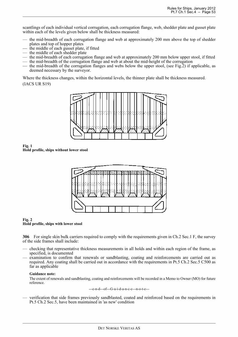
Rules for Ships, January 2012 Pt.7 Ch.1 Sec.4 – Page 53
scantlings of each individual vertical corrugation, each corrugation flange, web, shedder plate and gusset platewithin each of the levels given below shall be thickness measured:
— the mid-breadth of each corrugation flange and web at approximately 200 mm above the top of shedderplates and top of hopper plates
— the middle of each gusset plate, if fitted— the middle of each shedder plate— the mid-breadth of each corrugation flange and web at approximately 200 mm below upper stool, if fitted— the mid-breadth of the corrugation flange and web at about the mid-height of the corrugation— the mid-breadth of the corrugation flanges and webs below the upper stool, (see Fig.2) if applicable, as
deemed necessary by the surveyor.
Where the thickness changes, within the horizontal levels, the thinner plate shall be thickness measured.(IACS UR S19)
Fig. 1Hold profile, ships without lower stool
Fig. 2Hold profile, ships with lower stool
306 For single skin bulk carriers required to comply with the requirements given in Ch.2 Sec.1 F, the surveyof the side frames shall include:
— checking that representative thickness measurements in all holds and within each region of the frame, asspecified, is documented
— examination to confirm that renewals or sandblasting, coating and reinforcements are carried out asrequired. Any coating shall be carried out in accordance with the requirements in Pt.5 Ch.2 Sec.5 C500 asfar as applicable
Guidance note:The extent of renewals and sandblasting, coating and reinforcements will be recorded in a Memo to Owner (MO) for futurereference.
---e-n-d---of---G-u-i-d-a-n-c-e---n-o-t-e---
— verification that side frames previously sandblasted, coated and reinforced based on the requirements inPt.5 Ch.2 Sec.5, have been maintained in 'as new' condition
DET NORSKE VERITAS AS
Rules for Ships, January 2012 Pt.7 Ch.1 Sec.4 – Page 54
Guidance note:'As new' condition in this respect, means that the coating should be without any breakdown and rusting.
---e-n-d---of---G-u-i-d-a-n-c-e---n-o-t-e---
(IACS UR S31)
B 400 Oil and chemical tankers subject to Enhanced Survey Programme (class notation ESP) – additional requirements
401 For single hull oil tankers with double bottom or double side spaces (for water ballast, or void spaces), thesurvey requirements for double hull oil tankers shall be applied in way of the double bottom or the double sides.
402 Close-up examination shall be carried out in accordance with:
The survey of stainless steel tanks may be carried out as an overall examination supplemented by close-upexamination as deemed necessary by the surveyor.
403 Thickness measurements shall be carried out in accordance with:
Thickness measurement of stainless steel hull structure and piping may be waived, except for clad steel plating.
404 A bottom survey in dry dock shall be carried out in accordance with Sec.5 A, as part of the renewalsurvey.
405 Cargo tank boundaries facing ballast tanks, void spaces, pipe tunnels, pump rooms or cofferdams shall bepressure tested.All cargo tank bulkheads shall be pressure tested at the 2nd and subsequent renewal surveys.The pressure shall, in general, correspond to a head of liquid to the highest point that liquid will rise underservice conditions.Pressure testing of cargo tanks may be accepted based on confirmation from the Master, stating that thepressure testing has been carried out according to the requirements, with a satisfactory result.The testing of boundaries facing double bottom tanks and other spaces not designed for the carriage of liquidmay be omitted, provided a satisfactory internal examination together with an examination of the tanktop iscarried out.The surveyor may extend the tank testing as deemed necessary.
406 A ballast tank shall be recorded for examination at subsequent annual surveys where, in addition to theconditions given in 104 and 118:
— the hard protective coating is found to be less than GOOD condition and is not repaired to the satisfactionof the surveyor.
407 For independent cargo tanks in chemical tankers the survey shall include:
— thickness measurement as found necessary by the surveyor— hydraulically pressure testing of all tanks to their MARVS (Maximum Allowable Relief Valve Setting).
The testing of cargo tanks type a3 may be omitted if the tanks are found without corrosion and otherdamage and otherwise found acceptable by the surveyor.
B 500 Liquefied gas tankers – additional requirements
501 Close-up examination shall be carried out in accordance with Table D7.1.
502 Thickness measurement shall be carried out in accordance with Table D7.2.
503 A bottom survey in dry dock shall be carried out in accordance with Sec.5 A, as part of the renewal survey.
504 All cargo tanks are to be examined internally. Special attention shall be given to the cargo tank andinsulation in way of chocks, supports and keys. Removal of insulation may be required in order to verify thecondition of the tank or the insulation itself if found necessary by the Surveyor.Where the insulation arrangement is such that it cannot be examined, the surrounding structures of wing tanks,double bottom tanks and cofferdams shall be examined for cold spots when the cargo tanks are in the coldcondition (prior to the renewal survey) unless voyage records together with the instrumentation give sufficientevidence of the integrity of the insulation system.
Sec.4 Table D5.1 for single hull oil tankers and single hull chemical tankers,Sec.4 Table D6.1 for double hull oil tankers and double hull chemical tankers.
Sec.4 Table D5.2 for single hull oil tankers and single hull chemical tankers,Sec.4 Table D6.2 for double hull oil tankers and double hull chemical tankers.
DET NORSKE VERITAS AS

Rules for Ships, January 2012 Pt.7 Ch.1 Sec.4 – Page 55
505 Thickness measurements of the cargo tanks may be required if deemed necessary by the surveyor.
506 Non-destructive testing shall supplement cargo tank inspection, with special attention to be given to theintegrity of the main structural members, tank shell and highly stressed parts, including welded connections asdeemed necessary by the Surveyor. However, this does not mean that non-destructive testing can be dispensedwith totally. The following items are, inter alia, considered as highly stressed parts:
— cargo tank supports and anti-rolling or anti-pitching devices— web frames or stiffening rings— swash bulkhead boundaries— dome and sump connections to tank shell— foundations for pumps, towers, ladders etc.— pipe connections.
507 For independent tanks type B, the extent of non-destructive testing shall be as given in a programmespecially prepared for the cargo tank design.
508 The tightness of all cargo tanks shall be verified by an appropriate procedure. Provided that theeffectiveness of the ship's gas detection equipment has been confirmed, it will be acceptable to utilise thisequipment for the tightness test of independent tanks below deck during the first loading of the cargo tankssubsequent to the renewal survey.
509 Where findings of 501 to 508 or an examination of the voyage records raise doubts as to the structuralintegrity of a cargo tank, a hydraulic or hydro-pneumatic test shall be carried out. For integral tanks and forindependent tanks type A and B, the test pressure at top of the tank is not to be less than the MARVS (MaximumAllowable Relief Valve Setting). For cargo tanks type B with MARVS higher than 1.0 bar, a test pressurehigher than MARVS will be specially considered. For independent tanks type C the test pressure is not to beless than 1.25 times the MARVS.
510 For membrane containment systems a tightness test of the secondary barrier shall be carried out inaccordance with the system designers' procedures as approved by the Society
511 For membrane containment systems with glued secondary barriers the values obtained shall be comparedwith previous results or results obtained at newbuilding stage. If significant differences are observed for eachtank or between tanks, the surveyor shall require an evaluation and additional testing as necessary.
512 At every other special survey all independent cargo tanks type C shall be either:
— hydraulically or hydropneumatically tested to 1.25 times MARVS followed by non-destructive testing inaccordance with 506, or
— subjected to a thorough, planned non-destructive testing.
This testing shall be carried out in accordance with a programme specially prepared for the tank design. If aspecial programme does not exist, the following areas shall be given special attention:
— cargo tank supports and anti-rolling/anti-pitching devices,— stiffening rings,— Y-connections between tank shell and a longitudinal bulkhead of bilobe tanks,— swash bulkhead boundaries— dome and sump connections to the tank shell,— foundations for pumps, towers, ladders etc.,— pipe connections.
At least 10% of the length of the welded connections in each of above mentioned areas shall be tested. Thistesting shall be carried out internally and externally as applicable.Insulation shall be removed as necessary for the required non-destructive testing.
513 Secondary barriers shall be examined visually for their effectiveness. For containment systems whereaccess is not possible, the effectiveness of the secondary barrier may be checked by means of pressure/vacuumtests or other relevant methods.
514 For membrane and semi-membrane tank systems inspection and testing shall be carried out inaccordance with programmes specially prepared in accordance with an approved method for the actual tanksystem.
515 If installed, systems for heating of hull structures shall be surveyed and function tested.
DET NORSKE VERITAS AS
Rules for Ships, January 2012 Pt.7 Ch.1 Sec.4 – Page 56
516 All pressure relief valves for the cargo tanks shall be opened for examination, adjusted, function testedand sealed. The allowable tolerance on the set pressure is given in Table B2.
If the cargo tanks are equipped with relief valves with non-metallic membranes in the main or pilot valves, suchnon-metallic membranes shall be replaced with new ones.
517 Pressure/vacuum relief valves, pressure relief hatches and rupture discs on interbarrier spaces and holdspaces shall be examined, if necessary by opening, adjusted and tested depending on their design.
518 The cargo, liquid nitrogen and process piping systems, including valves, actuators, compensators etc.shall be opened for examination as deemed necessary. Insulation shall be removed as deemed necessary toascertain the condition of the pipes. If the visual examination raises doubt as to the integrity of the pipelines, apressure test at 1.25 times the MARVS for the pipeline shall be carried out. After reassembly the completepiping system shall be tightness-tested to MARVS.If the maximum delivery pressure for the piping system is less than the design pressure for the piping system,testing to the pumps' delivery pressure may be accepted. In such cases expansion bellows, selected at random,may be required dismantled for internal survey and pressure tested to their design pressure.
519 The pressure relief valves in the cargo and process piping systems shall be opened, function tested andadjusted to the extent found necessary by the surveyor.
520 The watersides of seawater-cooled heat exchangers, including those for gas operation of propulsionmachinery shall be opened for survey, and the heat exchangers shall be pressure tested as found necessary.
521 Cargo pumps, compressors and other machinery, including prime movers, used in connection with cargohandling and gas operation of propulsion machinery shall be surveyed.
522 The following portable equipment shall be surveyed:
— portable gas detectors, oxygen and humidity analysers— hoses and spool pieces used for segregation of piping systems for cargo, ventilation, inert gas and bilge
operation.
523 Water spray systems shall be surveyed and tested for correct functioning.
524 Systems for removal of water or cargo from interbarrier spaces and hold spaces shall be examined andtested as deemed necessary.
525 All gas-tight bulkheads shall be inspected. The effectiveness of gas-tight shaft sealings shall be verified.
C. Machinery and Systems
C 100 General - all ships
101 The survey shall cover:
a) propulsion system, see 102:b) steering and manoeuvring systems, see 103 and 106c) auxiliary systems, see 104d) boilers and thermal oil heaters, see 105e) auxiliary thrusters, see 106f) electrical power production systems including power management systems, see 107g) electrical installations, see 108h) electrical equipment in gas-dangerous spaces and zones, see 109i) control and monitoring system of main and auxiliary machinery including equipment for periodically
unattended machinery space and machinery centralised operated, see 110j) equipment and systems related to carriage of special cargoes:
— inert gas plants, see 111
Table B2 Cargo tanks - tolerance on set pressure Set pressure p
(bar)Tolerance
(%)0.0 ≤ p ≤ 1.5 ± 10.01.5 < p < 3.0 ± 6.0
3.0 ≤ p ± 3.0
DET NORSKE VERITAS AS

Rules for Ships, January 2012 Pt.7 Ch.1 Sec.4 – Page 57
— low flashpoint liquids, see 112— potable water, see 113
k) independent tanks within machinery area, fuel and lubrication oil tanks (non-integral, self-supporting tankswhich do not form part of the ship's hull), see 114
l) gas fuelled engine installations, see 115m) fuel cell installations, see 116n) gas turbine installations, see 117o) water ingress detection system and their alarms, for ships with single cargo hold and for bulk carriers, see
118.
102 The propulsion system shall be tested for proper functioning of the following:
— alarm and safety system— manual control of machinery— remote control of propulsion machinery— automatic control loops— transfer to stand-by manual control in the engine room in case of power supply failure to the remote control
system.
When cancelling of automatic load reduction and or automatic stop of engine are provided, these functions shallbe demonstrated to the satisfaction of the surveyor.The components in the propulsion system shall be examined and tested according to Table E1. Components arealso covered by separate surveys:
— Bottom survey - see Sec.5 A— Propeller shaft survey - see Sec.5 B— Propulsion connection survey - see Sec.5 C.— Thrusters for Main Propulsion and Dynpos survey, see Sec.5 D/E— Boiler survey, including steam generator, see Sec.5 F— Thermal oil heater, see Sec.5 G.
Water jets are covered by separate survey for High Speed, Light Craft and Naval Surface Craft (HS, LC andNSC).
103 The main and auxiliary steering gear arrangement shall be tested for proper functioning including test ofalarm and safety functions.
104 The auxiliary systems shall be tested for proper functioning including test of alarm and safety functions.The components in the auxiliary systems shall be examined and tested according to Table E1.
105 The following surveys shall be carried out in conjunction with the renewal survey:
— Boiler survey (boilers, superheaters, economisers and air preheaters or steam heated steam generator), seeSec.5 F.
— Thermal oil heater survey, see Sec.5 G.
106 Auxiliary thrusters shall be examined and tested as follows:
— Oil analysis of gear house oil and oil for the CP mechanism.— Examination of gear and bearings through inspection openings or by other means.— Examination of external piping systems.— Examination of bearings, gear and shafts and other relevant parts if any indications of abnormalities are
observed. Satisfactory maintenance according to manufacturer's recommendations to be documented andconsidered as a base for extent of possible opening.Opening to be carried out normally at least every 10 years.Any opening up of a thruster shall be witnessed by a surveyor of the Society.
— Function testing of sealing arrangements.— Function testing of lubrication and hydraulic oil system.— Function testing of CP mechanism.— Function testing of thruster unit including alarm system.
Guidance note:It is advised to take oil analysis at regular intervals and always prior to docking in order to ensure that there is no needfor opening of the thruster (e.g. water in the oil).
---e-n-d---of---G-u-i-d-a-n-c-e---n-o-t-e---
DET NORSKE VERITAS AS
Rules for Ships, January 2012 Pt.7 Ch.1 Sec.4 – Page 58
107 Electrical power production system including power management system and electrical installationsshall be tested for proper functioning.The following tests shall be carried out to the extent deemed necessary by the surveyor:
— generator full load test— generator parallel operation— generator protection relays including non-important load trip (if fitted)— generator remote speed control— generator synchronising equipment— power plant interlocking systems— emergency generator including switchboards— battery chargers.
108 Safety precautions with respect to shock, fire and explosion and other hazards of the electrical installationshall be examined for switchboards, distribution boards, cable installations, enclosures, converters (e.g. transformers,rectifiers, chargers), battery installations, lighting and heating equipment.Documentation of “Schedule of batteries” shall be reviewed.The following tests shall be carried out to the extent deemed necessary by the surveyor to ascertain the properfunctioning of the equipment:
— mechanical ventilation of battery rooms or lockers— navigation lights, with controllers including alarms.
The insulation resistance of the complete installation shall be measured. The results shall be presented to thesurveyor.
109 Electrical equipment in gas-dangerous spaces and zones shall be examined with respect to:
— corrosion— flameproof enclosure/ingress— no unauthorised modification— correct rating of lamps— earthing (spot check)— function testing of pressurised equipment and of associated alarms— testing of insulation resistance of power circuits (Ex p, Ex e and Ex n). Where proper records of testing are
maintained consideration may be given to accepting recent readings (maximum 12 months) by the ship'screw
— insulation monitors with alarms shall be function tested, if installed— for rooms protected by air locks, interlocking with ventilation of electrical supply to non-explosion
protected equipment and de-energising of such equipment in case of ventilation failure shall be examinedand function tested as applicable.
Guidance note:Megger testing in gas dangerous spaces may involve risk of explosion due to sparks. Therefore appropriate proceduresfor such work should be followed as relevant e.g., “gas free certificate”.
---e-n-d---of---G-u-i-d-a-n-c-e---n-o-t-e---
Guidance note:Reference is made to IACS Rec. No.35 - Inspection and maintenance of electrical equipment installed in hazardousareas.
---e-n-d---of---G-u-i-d-a-n-c-e---n-o-t-e---
110 The survey for control and monitoring system of main and auxiliary machinery shall include verificationof correct functioning of the following:
— each alarm system— each safety system— each fire detector in engine room— automatic control loops.
For ships with notation E0 or ECO, refer to Sec.6 Y.
111 For ships with inert gas plant (including ships with class notation INERT), the scrubber, deck water sealand non-return valves shall be opened up for examination.Pressure testing may be required if found relevant and necessary by the surveyor.
DET NORSKE VERITAS AS

Rules for Ships, January 2012 Pt.7 Ch.1 Sec.4 – Page 59
External examination and performance test shall be carried out for the following components andarrangements:
— deck water seal— non-return valves— scrubber cooling water arrangement— blowers including regulating valve and shut down devices— pressure/vacuum breaker— flue gas piping system— separate inert gas generator— running test, including check of instruments and automatic equipment.
Opening up and/or pressure testing may be required if found necessary by the surveyor.Last overhaul to be verified.It shall be verified that pipe blanking arrangements and portable O2-analysers are on board and in order.
112 For ships arranged for carriage of low flash point liquids (including ships with class notation LFL orLFL*), the survey shall include examination of heating coils, anodes, tank cleaning apparatus and otherequipment in cargo tanks and cofferdams. Heating coils are normally to be pressure tested.
113 For ships arranged for carriage of potable water (including ships with class notation Tanker forPotable Water), the following shall be examined:
— instruments for pH and conductivity— cargo tank vents.
114 Settling tank and daily service tanks for heavy fuel oil and diesel oil as well as lubrication oil circulationtanks assessed with respect to tank cleanliness.If inspection and cleaning have been carried out by the crew during the last 12 months and relevant log extractsare provided and confirmed, this may be credited as surveyed at the surveyor's discretion.Opening up of tanks may be required as found necessary by the surveyor.
115 For ships with gas fuelled engine installations, (including ships with class notation GAS FUELLED),the survey shall include:
a) examination of gastight bulkheads with cable and shaft sealing etc. Special attention shall be paid tobulkheads in the electrical motor and or compressor room. Shaft sealing shall be checked for lubricationand possible overheating
b) testing of gas tanks high level alarmc) examination and testing of:
— gas tanks safety relief valves— tank room or secondary barrier space P/V valves and relief hatches, as relevant— gas handling machinery and equipment— auxiliary systems and equipment for gas installations— portable gas detectors and oxygen analyser
116 For ships with fuel cell installations, (class notation FC- POWER and FC-SAFETY), the survey shallinclude as relevant:
a) examination of gastight bulkheads with cable and shaft sealing etc. Shaft sealing shall be checked forlubrication and possible overheating
b) testing of FC fuel tanks high level alarmc) examination and testing of:
— FC fuel tanks safety relief valves— tank room or secondary barrier space P/V valves and relief hatches, as relevant— FC fuel handling machinery and equipment— auxiliary systems and equipment for fuel cell installations— portable gas detectors and oxygen analyser.
117 For ships with gas turbine installations the survey shall include verification of records and majoroverhaul reports onboard. See Sec.1 C500 for general information on survey of gas turbines.
118 For ships with a single cargo*) hold and for bulk carriers**) an examination and test of the water ingressdetection system and of their alarms shall be carried out.
DET NORSKE VERITAS AS

Rules for Ships, January 2012 Pt.7 Ch.1 Sec.4 – Page 60
Guidance note:
*) For single hold cargo ships complying with the requirements of SOLAS II-I/23-3 and II-I/25, see Ch.2 Sec.2 D.**) For bulk carriers complying with the requirements of SOLAS XII/12 and XII/13, see Ch.2 Sec.1 E.
---e-n-d---of---G-u-i-d-a-n-c-e---n-o-t-e---
C 200 Oil and chemical tankers – additional requirements
201 Heating coils, tank cleaning apparatus and other equipment in cargo tanks, cofferdams and pipe tunnelswithin the cargo area shall be examined. Heating coils are normally to be pressure tested. Attachments ofsacrificial anodes in tanks shall be examined.
202 For ships having boilers burning crude oil or slop, examination and testing of control equipmentincluding monitoring systems and shut down functions related to the following systems shall be carried out:
— ventilation and gas-tightness, fuel supply line and boiler with boiler front lagging— fuel pumps and heating arrangement— drain pipe ducts and automatic closing drain traps— inert and purging systems— manual and automatic quick closing valves and shut-down systems— boiler hood ventilation system— boiler compartment ventilation— boiler front extinguishing system— pilot burner arrangement— gastight bulkhead penetrations— gas detection system— fuel heater.
203 For chemical tankers the survey shall include:
a) examination of systems for cargo heating and coolingb) checking of spare parts for the mechanical ventilation fans in the cargo areac) verification of the cargo system and equipment required in connection with the vessel's special features
notations (e.g. a1.2, b2.3, c3, f1.2, d2, k)d) testing of the instrumentation of the cargo plantse) examination and testing as appropriate of:
— valves for drop lines, gas return lines and automatic shut-down of loading— drip trays and spray shields— emergency discharge pumps.
f) verification of marking of cargo tanks, pumps, pipelines, valves etc.g) verification of the arrangement for discharge of contaminated waterh) the following shall be surveyed and tested:
— stripping tests of two cargo tanks, time of stripping shall be recorded.
204 For ships with centralised cargo control arrangement (including ships with class notation CCO), the surveyshall include:
— examination and testing of all remotely controlled operations related to cargo handling and ballasting— checking of alarms and remote readings according to Pt.6 Ch.6 Sec.2 Table C1— control of relevant requirements in Pt.4 Ch.9 Sec.4 in the case of computer based systems— examination and testing of arrangement for emergency stop of cargo pumps from the cargo manifold area— examination and testing of arrangement in cargo control room for emergency closing of valves in cargo
lines— testing of loading computer for the following functions as applicable:
— damage stability and strength (by simulating loading conditions)— cargo compatibility with tank coating— certificate limitations.
205 For ships with vapour processing and recovery plant (including ships with class notation VCS-3) thesurvey shall include a VOC (volatile organic compounds) plant running test.
C 300 Liquefied gas tankers – additional requirements
301 The ventilation systems for spaces in the cargo area shall be examined and function tested.
DET NORSKE VERITAS AS

Rules for Ships, January 2012 Pt.7 Ch.1 Sec.4 – Page 61
Confirmation that spares are provided for cargo area mechanical ventilation fans (not required if double fansprovided).
302 For rooms protected by air locks, interlocking with ventilation of electrical supply to non-explosionprotected equipment and de-energising of such equipment in case of ventilation failure shall be examined andfunction tested as applicable.
303 The instrumentation of the different cargo installations shall be tested by changing the parameter asapplicable and comparing with test instruments. Simulated testing may be accepted for sensors which are notaccessible or for sensors located within cargo tanks or inerted hold spaces. The testing shall include testing ofalarm and safety functions.
304 For ships having a gas fuel forwarding system, the safety and control equipment and alarm and shut downfunctions related to the following systems shall be tested:
— gas heating arrangement— fuel gas compressor and forwarding system— ventilation arrangement— protection and flame screens— gas freeing and purging systems— manual and automatic shut-down system— gas detection system— pilot flame burner or “fuel floor” arrangement, if applicable— governor stability switching from gas fuel to oil, or vice versa.
D. Tables of Close-Up Examination and Thickness Measurements
D 100 General - All ships
101 Minimum thickness measurements, all ships are given in Table D1.1, for passenger ships in Table D1.1.1and for ships with class notation Great Lakes Bulk Carriers in Table D1.1.2.
102 Thickness measurements, extent and pattern in way of areas with substantial corrosion, all ships are given inTable D1.2
D 200 General dry cargo ships subject to Extended Hull Survey Requirements (EHSR)
201 Close-up examination, general dry cargo ships are given in Table D2.1
202 Minimum thickness measurements, general dry cargo ships are given in Table D2.2
D 300 Single skin bulk carriers subject to Enhanced Survey Programme (class notation ESP)
301 Close-up examination, single skin bulk carriers are given in Table D3.1
302 Minimum thickness measurement, single skin bulk carriers are given in Table D3.2
303 Thickness measurements, extent and pattern in way of areas with substantial corrosion, single skin bulkcarriers are given in Table D3.3
D 400 Double skin bulk carriers subject to Enhanced Survey Programme (class notation ESP)
401 Close-up examination, double skin bulk carriers are given Table D4.1
402 Close-up examination, ore carriers are given Table D4.1.1.
403 Minimum thickness measurement, double skin bulk carriers and ore carriers are given in Table D4.2
404 Thickness measurement, extent and pattern in way of areas of substantial corrosion, double skin bulkcarriers are given in Table D4.3
D 500 Single hull oil tankers and single hull chemical tankers subject to Enhanced Survey Programme (class notation ESP)
501 Close-up examination, single hull oil tankers, single hull chemical tankers and ore/oil ships are given inTable D5.1
502 Minimum thickness measurement, single hull oil tankers, single hull chemical tankers and ore/oil shipsare given in Table D5.2
503 Thickness measurement, extent and pattern in way of areas of substantial corrosion, single hull oiltankers, single hull chemical tankers and ore/oil ships are given in Table D5.3
DET NORSKE VERITAS AS

Rules for Ships, January 2012 Pt.7 Ch.1 Sec.4 – Page 62
D 600 Double hull oil tankers subject to Enhanced Survey Programme (class notation ESP)
601 Close-up examination, double hull oil tankers and double hull chemical tankers are given in Table D6.1
602 Minimum thickness measurement, double hull oil tankers and double hull chemical tankers are given inTable D6.2
603 Thickness measurement, extent and pattern in way of areas of substantial corrosion, double hull oiltankers and double hull chemical tankers are given in Table D6.3
D 700 Liquefied gas tankers
701 Close-up examination, liquefied gas tankers are given Table D7.1.
702 Minimum thickness measurement, liquefied gas tankers are given in Table D7.2.
Table D1.1 Minimum thickness measurements 1), all ships
AreaRenewal survey
no. 1Age ≤ 5 years
Renewal survey no. 2
Age 5 - 10 years
Renewal survey no. 3Age 10 - 15 years
Renewal survey no. 4 and subsequentAge > 15 years
0 Transverse section(s) in way of cargo area within 0.5 L amidships 2)4)
One section of deck plating only.
Two complete sections - two different spaces. 5)
Three complete sections. 5)
1a Main deck plating 3) All exposed - full length. 1b Cargo hold hatch covers
and coamingsAll - plating and stiffeners.
All - plating and stiffeners.
2 Wind- and water strakes All - full length. 3 Strakes of transverse
bulkheads in cargo spaces together with internals in way
All bulkheads - lowest strake and strakes in way of 'tween decks.
4a Keel plates and bottom plates
All keel plates full length. Additional bottom plates in way of cofferdams, machinery space and aft end of tanks.
4b Plating of sea chests and shell plating in way of overboard discharges
Plating of sea chests.Shell plating as considered necessary by the attending surveyor.
5 Superstructure deck plating (poop, bridge and forecastle deck)
Representative exposed deck plating.
6 Internals in peak tanks Forepeak and aftpeak.
Forepeak and aftpeak.
7 Air pipes and ventilators All - on the fore deck (forward quarter length).All exposed air pipes to fuel and lube oil daily service tanks.Selected air pipes and ventilator coamings aft of the forward quarter.
All - on the fore deck (forward quarter length).All exposed air pipes to fuel and lube oil daily service tanks.Selected air pipes and ventilator coamings aft of the forward quarter.
Notes:
1) Thickness measurement locations should be selected to provide the best representative sampling of areas likely to be most exposed to corrosion, considering cargo and ballast history and arrangement and condition of protective coatings.
2) For ships less than 100 m in length, the number of transverse section required at renewal survey no. 3 and subsequent renewal surveys may be reduced by one (to 1 and 2 respectively).
3) For ships more than 100 m in length, at renewal survey no. 3, thickness measurements of exposed deck plating within 0.5 L may be required.
4) Transverse sections shall be chosen where the largest reductions are suspected to occur or are revealed from deck plating measurements.
5) At least one section shall include a ballast tank, as far as applicable.Source.: IACS UR Z7 TABLE I
DET NORSKE VERITAS AS

Rules for Ships, January 2012 Pt.7 Ch.1 Sec.4 – Page 63
Table D1.1.1 Minimum thickness measurements 1), passenger ships with superstructure extending over most of the ship length
AreaRenewal survey
no. 1Age ≤ 5 years
Renewal survey no. 2
Age 5 - 10 years
Renewal survey no. 3
Age 10 - 15 years
Renewal survey no. 4 and subsequentAge > 15 years
0 Transverse section(s) within 0.5 L amidships 2)3)
. Two sections of hull plating (keel, bottom & bilge, side) up to the bulkhead deck.
Three sections of hull plating (keel, bottom & bilge, side) up to the bulkhead deck.
1a Tank top plating 4) Selected plating within machinery and boiler spaces.
Selected plating within machinery and boiler spaces.
Selected plating within machinery and boiler spaces.
1b Car decks plating Selected plating. All plating.2 Wind- and water strakes All - full length. 3 Strakes of transverse
bulkheads in machinery and cargo spaces as applicable together with internals in way
All bulkheads - lowest strake.
4a Keel plates and bottom plates
All keel plates full length. Additional bottom plates in way of cofferdams, machinery space and aft end of tanks.
4b Plating of sea chests and shell plating in way of overboard discharges
Plating of sea chests.Shell plating as considered necessary by the attending surveyor.
5 Superstructure deck plating
Representative exposed deck plating.
Representative exposed deck plating.
6 Internals in peak tanks Forepeak and aft peak.
Forepeak and aft peak.
Notes:
1) Thickness measurement locations should be selected to provide the best representative sampling of areas likely to be most exposed to corrosion, considering ballast history and arrangement and condition of protective coatings.
2) For ships less than 100 m in length, the number of transverse section required at renewal survey no. 3 and subsequent renewal surveys may be reduced by one (to 1 and 2 respectively).
3) Transverse sections shall be chosen where the largest reductions are suspected to occur and shall normally include ballast tanks, as far as applicable.
4) Special attention shall be given to areas within spaces where water may accumulate, i.e. in way of boilers, water makers, spaces with sewage treatment plants, areas around penetrations for steam pipes and areas showing signs of water leakage.
DET NORSKE VERITAS AS

Rules for Ships, January 2012 Pt.7 Ch.1 Sec.4 – Page 64
Table D1.1.2 Minimum thickness measurements 1), Great Lakes Bulk Carriers
Area Renewal survey no. 1 and 2
Renewal survey no. 3 Renewal survey no. 4- 6
Renewal survey no. 7 and subsequent
0a Transverse sections within the cargo area. 2)
One complete section - outside line of cargo hatch openings - within 0.5 L amidships. 3)
0b Unprotected ballast tanks / possible suspect area / extensive corrosion
In case extensive corrosion is found, thickness measurements are to be carried out to the extent deemed necessary by the surveyor and may be equal to those required for sea going vessels, i.e. D3.2
In case extensive corrosion is found, thickness measurements are to be carried out to the extent deemed necessary by the surveyor and may be equal to those required for sea going vessels, i.e. D3.2
In case extensive corrosion is found, thickness measurements are to be carried out to the extent deemed necessary by the surveyor and may be equal to those required for sea going vessels, i.e. D3.2
In case extensive corrosion is found, thickness measurements are to be carried out to the extent deemed necessary by the surveyor and may be equal to those required for sea going vessels, i.e. D3.2
1a Cargo hold hatch covers – plating and stiffeners
Selected hatch covers to be decided by the surveyor.
Selected hatch covers to be decided by the surveyor.
2 Cargo hold transverse shell frames
Selected frames in forward cargo hold and selected frames in one more hold.
25% of frames in the forward cargo hold at representative positions. Selected frames in remaining cargo holds.
3 Transverse bulkheads
Selected transverse bulkheads within cargo area.
Collision bulkhead and selected transverse bulkheads within cargo area.
6 Internals in peak tanks.
Forepeak and aftpeak.
Forepeak and aftpeak.
7 Air pipes and ventilators
Selected air pipes on the fore deck (forward quarter length). All air pipes to day tanks.
All - on the fore deck (forward quarter length). All air pipes to day tanks. Selected air pipes and ventilator coaming aft of the forward quarter.
Notes:
1) Thickness measurement locations should be selected to provide the best representative sampling of areas likely to be most exposed to corrosion, considering cargo and ballast history and arrangement and condition of protective coatings.
2) Transverse sections shall be chosen where the largest reductions are suspected to occur.
3) The section shall include a ballast tank, as far as applicable.
Table D1.2 Thickness measurements, extent and pattern in way of areas with substantial corrosion, all shipsArea / Structural member Extent of measurement Pattern of measurement
Plating Suspect area and adjacent plates 5 points over 1 m2 Stiffeners Suspect area 3 points in line across web
3 points in line across flange Source.: IACS UR Z7 TABLE II
DET NORSKE VERITAS AS

Rules for Ships, January 2012 Pt.7 Ch.1 Sec.4 – Page 65
Table D2.1 Close-up examination, general dry cargo ships
AreaRenewal survey
no. 1Age ≤ 5 years
Renewal survey no. 2
Age 5 - 10 years
Renewal survey no. 3
Age 10 - 15 years
Renewal survey no. 4 and subsequentAge > 15 years
1a Cargo hold hatch covers and coamings - plating and stiffeners.
All All All All
1b Deck plating and underdeck structures inside line of hatch openings between cargo hold hatches.
Selected areas All All
2 Cargo hold transverse shell frames.
Selected frames in one forward and one aft cargo hold/ 'tween deck space.
Selected frames in all cargo holds/ 'tween deck spaces.
All frames in the forward lower cargo hold and 25% of frames in each of the remaining cargo holds/ 'tween deck spaces including upper and lower end attachments and adjacent shell plating.
All frames in all cargo holds/ 'tween deck spaces including upper and lower end attachments and adjacent shell plating.
3a Cargo hold transverse bulkheads 1) - plating, stiffeners and girders.
One One in each hold. All All
3b Ballast tanks transverse bulkheads, including stiffening system.
Forward and aft bulkhead in one side tank.
All All
4a Ballast tanks transverse web frames with associated plating and framing.
One in two representative tanks of each type within the cargo area 2).
All - in all ballast tanks
All - in all ballast tanks
4b Inner bottom plating. Selected areas All AllNotes:
1) Close-up examination of cargo hold transverse bulkheads to be carried out at the following levels:
— Immediately above the inner bottom and immediately above the 'tween decks, as applicable.— About mid-height of the bulkheads for holds without 'tween deck.— Immediately below the main deck and immediately below the 'tween deck, as applicable.
2) Ballast tank types within the cargo area: top side tank, double side tank, hopper side tank, double bottom tank.Source.: IACS UR Z7 TABLE I
DET NORSKE VERITAS AS

Rules for Ships, January 2012 Pt.7 Ch.1 Sec.4 – Page 66
Table D2.2 Minimum thickness measurements1), general dry cargo ships
AreaRenewal survey
no. 1Age ≤ 5 years
Renewal survey no. 2
Age 5 - 10 years
Renewal survey no. 3
Age 10 - 15 years
Renewal survey no. 4 and subsequentAge > 15 years
0a Transverse section(s) in way of cargo area within 0.5L amidships 2)3).
One section of deck plating only.
Two complete sections - two different cargo spaces. 4)
Three complete sections. 4)
0b Structural members subject to close-up examination according to Table D2.1.
Measurements, for general assessment and recording of corrosion pattern.
Measurements, for general assessment and recording of corrosion pattern.
Measurements, for general assessment and recording of corrosion pattern.
Measurements, for general assessment and recording of corrosion pattern.
1 Main deck plating All - outside line of cargo hatch openings within the cargo area.
All - outside line of cargo hatch openings within the cargo area. All exposed - outside the cargo area.
2 Wind- and water strakes. All - within the cargo area. Selected outside the cargo area.
All - full length.
3 Transverse bulkheads See item 0b See item 0b See item 0b See item 0b4a Keel plates and bottom
plates.All keel plates full length. All bottom plates, including lower turn of bilge, within the cargo area.Additional bottom plates in way of cofferdams, machinery space and aft end of tanks.
4b Sea chests and shell plating in way of overboard discharges.
Plating of sea chests.Shell plating as considered necessary by the attending surveyor.
4c Duct keel or pipe tunnel. Plating and internals. 5 Superstructure deck
plating (poop, bridge and forecastle deck).
Representative exposed deck plating.
6 Internals in peak tanks. Forepeak and aftpeak.
Forepeak and aftpeak.
7 Air pipes and ventilators All - on the fore deck (forward quarter length).All exposed air pipes to fuel and lube oil daily service tanks.Selected air pipes and ventilator coamings aft of the forward quarter.
All - on the fore deck (forward quarter length).All exposed air pipes to fuel and lube oil daily service tanks.Selected air pipes and ventilator coamings aft of the forward quarter.
Note:
1) Thickness measurement locations should be selected to provide the best representative sampling of areas likely to be most exposed to corrosion, considering cargo and ballast history and arrangement and condition of protective coatings.
2) For ships less than 100 m in length, the number of transverse section required at renewal survey no. 3 may be reduced to one (1), and the number of transverse sections at subsequent renewal surveys may be reduced to two (2).
3) Transverse sections shall be chosen where the largest reductions are suspected to occur or are revealed from deck plating measurements.
4) At least one section shall include a ballast tank, as far as applicable.Source.: IACS UR Z7.1 TABLE II
DET NORSKE VERITAS AS

Rules for Ships, January 2012 Pt.7 Ch.1 Sec.4 – Page 67
Table D3.1 Close-up examination, single skin bulk carriers
AreaRenewal survey
no. 1Age ≤ 5 years
Renewal survey no. 2
Age 5 - 10 years
Renewal survey no. 3
Age 10 - 15 years
Renewal survey no. 4 and subsequentAge > 15 years
1a Cargo hold hatch covers and coamings - plating and stiffeners.
All All All All
1b Deck plating and underdeck structures inside line of hatch openings between cargo hold hatches.
All All All
2 Cargo hold transverse shell frames.
25% of frames in the forward cargo hold at representative positions.Selected frames in remaining cargo holds.
All frames in the forward cargo hold and 25% of frames in each of the remaining cargo holds, including upper and lower end attachments and adjacent shell plating.For bulk carriers 100 000 dwt and above, all shell frames in the forward cargo hold and 50% of shell frames in each of the remaining cargo holds, including upper and lower end attachments and adjacent shell plating.
All frames in the forward and one other selected cargo hold and 50% of frames in each of the remaining cargo holds, including upper and lower end attachments and adjacent shell plating.
All frames in all cargo holds, including upper and lower end attachments and adjacent shell plating.
3a Cargo hold transverse bulkheads 1) - plating, stiffeners and girders, including internal structures of upper and lower stools, where fitted.
Two selected bulkheads.
All All All
3b Ballast tanks transverse bulkheads, including stiffening system.
Forward and aft bulkhead in one side tank.
All All
4a Ballast tanks transverse web frames with associated plating and longitudinals.
One in two representative tanks of each type within the cargo area 2).
One in each tank within the cargo area2).
All - in all ballast tanks
All - in all ballast tanks
Notes:
1) Close-up examination of cargo hold transverse bulkheads to be carried out at the following levels:
Level (a)Immediately above the inner bottom and immediately above the line of gussets (if fitted) and shedders for ships without lower stool.
Level (b)Immediately above and below the lower stool shelf plate (for those ships fitted with lower stools), and immediately above the line of the shedder plates.
Level (c)About mid-height of the bulkhead.Level (d)Immediately below the upper deck plating and immediately adjacent to the upper wing tank, and
immediately below the upper stool shelf plate for those ships fitted with upper stools, or immediately below the topside tanks.
2) Ballast tank types within the cargo area: top side tank, hopper side tank, double bottom tank.Source.: IACS UR Z10.2 TABLE I
DET NORSKE VERITAS AS
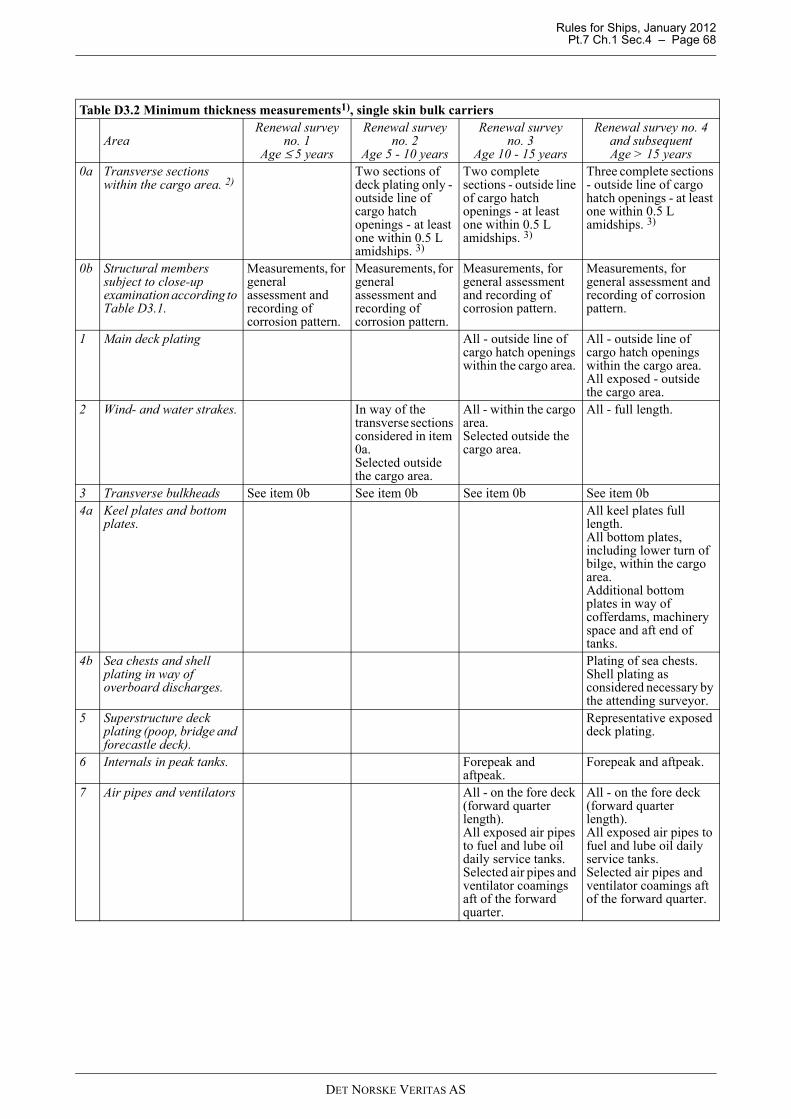
Rules for Ships, January 2012 Pt.7 Ch.1 Sec.4 – Page 68
Table D3.2 Minimum thickness measurements1), single skin bulk carriers
AreaRenewal survey
no. 1Age ≤ 5 years
Renewal survey no. 2
Age 5 - 10 years
Renewal survey no. 3
Age 10 - 15 years
Renewal survey no. 4 and subsequentAge > 15 years
0a Transverse sections within the cargo area. 2)
Two sections of deck plating only - outside line of cargo hatch openings - at least one within 0.5 L amidships. 3)
Two complete sections - outside line of cargo hatch openings - at least one within 0.5 L amidships. 3)
Three complete sections - outside line of cargo hatch openings - at least one within 0.5 L amidships. 3)
0b Structural members subject to close-up examination according to Table D3.1.
Measurements, for general assessment and recording of corrosion pattern.
Measurements, for general assessment and recording of corrosion pattern.
Measurements, for general assessment and recording of corrosion pattern.
Measurements, for general assessment and recording of corrosion pattern.
1 Main deck plating All - outside line of cargo hatch openings within the cargo area.
All - outside line of cargo hatch openings within the cargo area. All exposed - outside the cargo area.
2 Wind- and water strakes. In way of the transverse sections considered in item 0a. Selected outside the cargo area.
All - within the cargo area. Selected outside the cargo area.
All - full length.
3 Transverse bulkheads See item 0b See item 0b See item 0b See item 0b4a Keel plates and bottom
plates.All keel plates full length. All bottom plates, including lower turn of bilge, within the cargo area.Additional bottom plates in way of cofferdams, machinery space and aft end of tanks.
4b Sea chests and shell plating in way of overboard discharges.
Plating of sea chests.Shell plating as considered necessary by the attending surveyor.
5 Superstructure deck plating (poop, bridge and forecastle deck).
Representative exposed deck plating.
6 Internals in peak tanks. Forepeak and aftpeak.
Forepeak and aftpeak.
7 Air pipes and ventilators All - on the fore deck (forward quarter length).All exposed air pipes to fuel and lube oil daily service tanks.Selected air pipes and ventilator coamings aft of the forward quarter.
All - on the fore deck (forward quarter length).All exposed air pipes to fuel and lube oil daily service tanks.Selected air pipes and ventilator coamings aft of the forward quarter.
DET NORSKE VERITAS AS

Rules for Ships, January 2012 Pt.7 Ch.1 Sec.4 – Page 69
8 Vertically corrugated transverse watertight bulkhead between cargo hold Nos. 1 and 2 - Ships subject to compliance with the requirements given in Ch.2 Sec.1 A.
Additional requirements as given in B305
Additional requirements as given in B305
Additional requirements as given in B305
9 Side shell frames and brackets - Ships subject to compliance with the requirements given in Ch.2 Sec.1 F.
Additional requirements as given in B306
Additional requirements as given in B306
Additional requirements as given in B306
Note:
1) Thickness measurement locations should be selected to provide the best representative sampling of areas likely to be most exposed to corrosion, considering cargo and ballast history and arrangement and condition of protective coatings.
2) Transverse sections shall be chosen where the largest reductions are suspected to occur or are revealed from deck plating measurements.
3) At least one section shall include a ballast tank, as far as applicable.Source.: IACS UR Z10.2 TABLE II
Table D3.3 Thickness measurements, extent and pattern in way of areas with substantial corrosion, single skin bulk carriers
Area / Structural member Extent of measurement Pattern of measurement1a Main deck
structuresDeck plating. Suspect plate(s) and four
adjacent plates. 5 points over 1 m2 of plating.
Deck longitudinals.
Three longitudinals in way of suspect area.
5 points both web and flange over 1 m length.
Web frames or transverses.
Suspect plate(s) 5 points over 1 m2 of plating.
1b Deck cross strips
Plating. Suspect plate(s). 5 points between stiffeners over 1 m length.Underdeck stiffeners.
Transverse members. 5 points at each end and midspan.Longitudinal members. 5 points on both web and flange.
1c Hatch covers and coamings
Hatch covers. Three locations on each side and end skirts.
5 points at each location.
Two outboard strakes longitudinal bands.One centerline strake longitudinal band.
5 points each band.
Hatch coamings. One transverse band at lower 1/3 of each end.One transverse band at upper 2/3 of each end.
5 points each band.
One longitudinal band at lower 1/3 of each side.One longitudinal band at upper 2/3 of each side.
5 points each band.
Table D3.2 Minimum thickness measurements1), single skin bulk carriers (Continued)
AreaRenewal survey
no. 1Age ≤ 5 years
Renewal survey no. 2
Age 5 - 10 years
Renewal survey no. 3
Age 10 - 15 years
Renewal survey no. 4 and subsequentAge > 15 years
DET NORSKE VERITAS AS

Rules for Ships, January 2012 Pt.7 Ch.1 Sec.4 – Page 70
1d Top side ballast tanks.
Watertight transverse bulkhead.
Lower 1/3 of bulkhead. 5 points over 1 m2 of plating.Upper 2/3 of bulkhead. 5 points over 1 m2 of plating.Stiffeners. 5 points over 1 m length.
Swash transverse bulkhead.
Lower 1/3 of 2 representative bulkheads.
5 points over 1 m2 of plating.
Upper 2/3 of 2 representative bulkheads.
5 points over 1 m2 of plating.
Stiffeners. 5 points over 1 m length.Sloping tank bottom.
Three representative bays at lower 1/3 of tank.
5 points over 1 m2 of plating.
Three representative bays at upper 2/3 of tank.
5 points over 1 m2 of plating.
Longitudinals, suspect and adjacent.
5 points both web and flange over 1 m length.
2 Single side structures.
Side shell plating. Suspect plate(s) and all adjacent plates.
5 points each panel between longitudinals.
Side shell frames. Suspect frame(s) and each adjacent frame.
5 points across both web and flange at each end and midspan.5 points within 25 mm of welded attachment to both shell and lower slope plate.
3 Transverse bulkhead structures in cargo holds.
Lower stool. Transverse band within 25 mm of welded connection to inner bottom.
5 points between stiffeners over 1 m length.
Transverse band within 25 mm of welded connection to shelf plate.
5 points between stiffeners over 1 m length.
Bulkhead. Transverse band at approximately mid height
5 points over 1 m2 of plating.
Transverse band adjacent to upper deck or shelf plate of upper stool, whichever is applicable.
5 points over 1 m2 of plating.
4 Double bottom and hopper structures.
Bottom, inner bottom and hopper structures plating.
Suspect plate(s) and all adjacent plates.
5 points each panel between longitudinals over 1 m length.
Bottom, inner bottom and hopper structures longitudinals.
Three longitudinals where plates measured.
3 points in line across web.3 points in line across flange.
Longitudinal girders or transverse floors.
Suspect plate(s) 5 points over 1 m2 of plating.
Watertight bulkheads (WT floors)
Plating lower 1/3 of tank. 5 points over 1 m2 of plating.
Plating upper 2/3 of tank. 5 points alternate plates over 1 m2 of plating.Web frames Suspect plate(s) 5 points over 1 m2 of plating.
Source.: IACS UR Z10.2 TABLEVIII
Table D3.3 Thickness measurements, extent and pattern in way of areas with substantial corrosion, single skin bulk carriers (Continued)
Area / Structural member Extent of measurement Pattern of measurement
DET NORSKE VERITAS AS
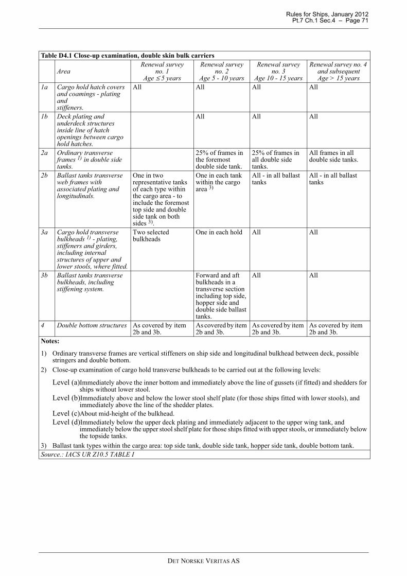
Rules for Ships, January 2012 Pt.7 Ch.1 Sec.4 – Page 71
Table D4.1 Close-up examination, double skin bulk carriers
AreaRenewal survey
no. 1Age ≤ 5 years
Renewal survey no. 2
Age 5 - 10 years
Renewal survey no. 3
Age 10 - 15 years
Renewal survey no. 4 and subsequentAge > 15 years
1a Cargo hold hatch covers and coamings - plating and stiffeners.
All All All All
1b Deck plating and underdeck structures inside line of hatch openings between cargo hold hatches.
All All All
2a Ordinary transverse frames 1) in double side tanks.
25% of frames in the foremost double side tank.
25% of frames in all double side tanks.
All frames in all double side tanks.
2b Ballast tanks transverse web frames with associated plating and longitudinals.
One in two representative tanks of each type within the cargo area - to include the foremost top side and double side tank on both sides 3).
One in each tank within the cargo area 3)
All - in all ballast tanks
All - in all ballast tanks
3a Cargo hold transverse bulkheads 1) - plating, stiffeners and girders, including internal structures of upper and lower stools, where fitted.
Two selected bulkheads
One in each hold All All
3b Ballast tanks transverse bulkheads, including stiffening system.
Forward and aft bulkheads in a transverse section including top side, hopper side and double side ballast tanks.
All All
4 Double bottom structures As covered by item 2b and 3b.
As covered by item 2b and 3b.
As covered by item 2b and 3b.
As covered by item 2b and 3b.
Notes:
1) Ordinary transverse frames are vertical stiffeners on ship side and longitudinal bulkhead between deck, possible stringers and double bottom.
2) Close-up examination of cargo hold transverse bulkheads to be carried out at the following levels:
Level (a)Immediately above the inner bottom and immediately above the line of gussets (if fitted) and shedders for ships without lower stool.
Level (b)Immediately above and below the lower stool shelf plate (for those ships fitted with lower stools), and immediately above the line of the shedder plates.
Level (c)About mid-height of the bulkhead.Level (d)Immediately below the upper deck plating and immediately adjacent to the upper wing tank, and
immediately below the upper stool shelf plate for those ships fitted with upper stools, or immediately below the topside tanks.
3) Ballast tank types within the cargo area: top side tank, double side tank, hopper side tank, double bottom tank.Source.: IACS UR Z10.5 TABLE I
DET NORSKE VERITAS AS
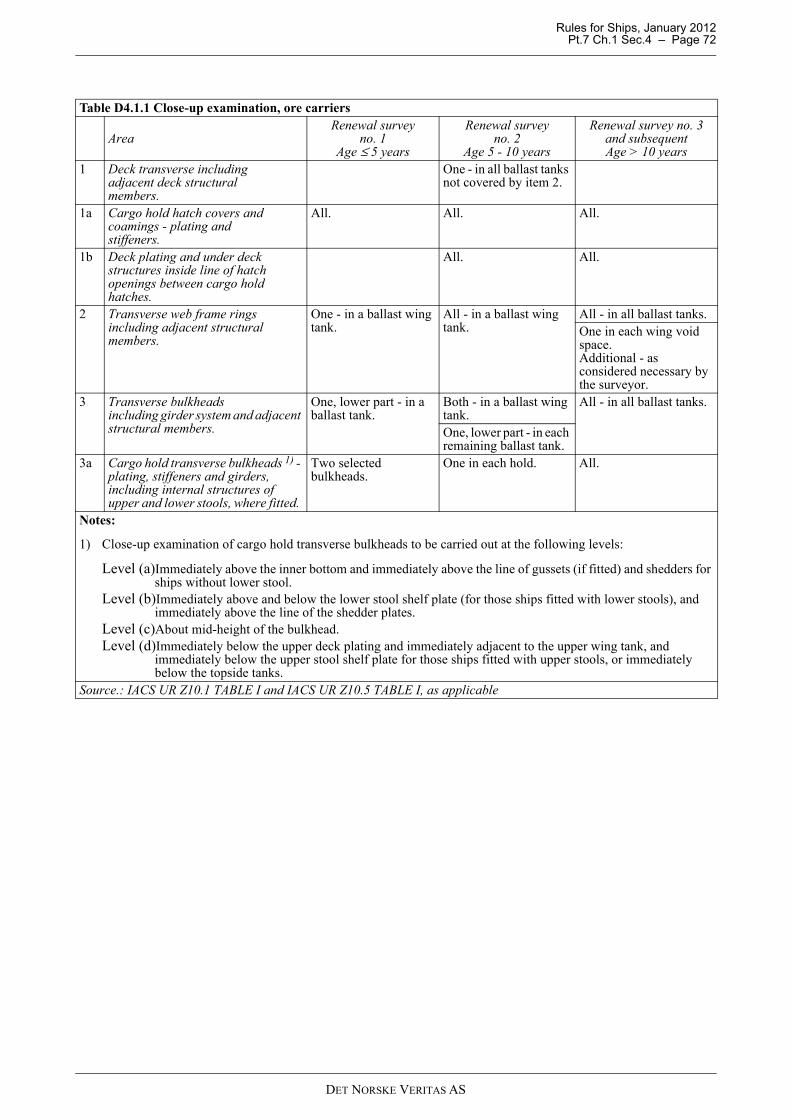
Rules for Ships, January 2012 Pt.7 Ch.1 Sec.4 – Page 72
Table D4.1.1 Close-up examination, ore carriers
AreaRenewal survey
no. 1Age ≤ 5 years
Renewal survey no. 2
Age 5 - 10 years
Renewal survey no. 3 and subsequentAge > 10 years
1 Deck transverse including adjacent deck structural members.
One - in all ballast tanks not covered by item 2.
1a Cargo hold hatch covers and coamings - plating and stiffeners.
All. All. All.
1b Deck plating and under deck structures inside line of hatch openings between cargo hold hatches.
All. All.
2 Transverse web frame rings including adjacent structural members.
One - in a ballast wing tank.
All - in a ballast wing tank.
All - in all ballast tanks.One in each wing void space.Additional - as considered necessary by the surveyor.
3 Transverse bulkheads including girder system and adjacent structural members.
One, lower part - in a ballast tank.
Both - in a ballast wing tank.
All - in all ballast tanks.
One, lower part - in each remaining ballast tank.
3a Cargo hold transverse bulkheads 1) - plating, stiffeners and girders, including internal structures of upper and lower stools, where fitted.
Two selected bulkheads.
One in each hold. All.
Notes:
1) Close-up examination of cargo hold transverse bulkheads to be carried out at the following levels:
Level (a)Immediately above the inner bottom and immediately above the line of gussets (if fitted) and shedders for ships without lower stool.
Level (b)Immediately above and below the lower stool shelf plate (for those ships fitted with lower stools), and immediately above the line of the shedder plates.
Level (c)About mid-height of the bulkhead.Level (d)Immediately below the upper deck plating and immediately adjacent to the upper wing tank, and
immediately below the upper stool shelf plate for those ships fitted with upper stools, or immediately below the topside tanks.
Source.: IACS UR Z10.1 TABLE I and IACS UR Z10.5 TABLE I, as applicable
DET NORSKE VERITAS AS

Rules for Ships, January 2012 Pt.7 Ch.1 Sec.4 – Page 73
Table D4.2 Minimum thickness measurements1), double skin bulk carriers and ore carriers
AreaRenewal survey
no. 1Age ≤ 5 years
Renewal survey no. 2
Age 5 - 10 years
Renewal survey no. 3
Age 10 - 15 years
Renewal survey no. 4 and subsequentAge > 15 years
0a Transverse sections within the cargo area. 2)
Two section of deck plating only - outside line of cargo hatch openings - at least one within 0.5 L amidships. 3)
Two complete sections - outside line of cargo hatch openings - at least one within 0.5 L amidships. 3)
Three complete sections - outside line of cargo hatch openings - at least one within 0.5 L amidships. 3)
0b Structural members subject to close-up examination according to Table D4.1 and Table D4.1.1.
Measurements, for general assessment and recording of corrosion pattern.
Measurements, for general assessment and recording of corrosion pattern.
Measurements, for general assessment and recording of corrosion pattern.
Measurements, for general assessment and recording of corrosion pattern.
1 Main deck plating All - outside line of cargo hatch openings, within the cargo area.
All - outside line of cargo hatch openings, within the cargo area. All exposed - outside cargo area.
2 Wind- and water strakes.
In the transverse sections considered in item 0a. Selected outside the cargo area.
All - within the cargo area. Selected outside the cargo area.
All - full length.
3 Transverse bulkheads See item 0b See item 0b See item 0b See item 0b4a Keel plates and bottom
plates.All keel plates full length. All bottom plates, including lower turn of bilge, within the cargo area.Additional bottom plates in way of cofferdams, machinery space and aft end of tanks.
4b Sea chests and shell plating in way of overboard discharges.
Plating of sea chests.Shell plating as considered necessary by the attending surveyor.
5 Superstructure deck plating (poop, bridge and forecastle deck).
Representative exposed deck plating.
6 Internals in peak tanks. Forepeak and aftpeak.
Forepeak and aftpeak.
7 Air pipes and ventilators
All - on the fore deck (forward quarter length).All exposed air pipes to fuel and lube oil daily service tanks.Selected air pipes and ventilator coamings aft of the forward quarter.
All - on the fore deck (forward quarter length).All exposed air pipes to fuel and lube oil daily service tanks.Selected air pipes and ventilator coamings aft of the forward quarter.
Note:
1) Thickness measurement locations should be selected to provide the best representative sampling of areas likely to be most exposed to corrosion, considering cargo and ballast history and arrangement and condition of protective coatings.
2) Transverse sections shall be chosen where the largest reductions are suspected to occur or are revealed from deck plating measurements.
3) At least one section shall include a ballast tank, as far as applicable.Source.: IACS UR Z10.5 TABLE II
DET NORSKE VERITAS AS
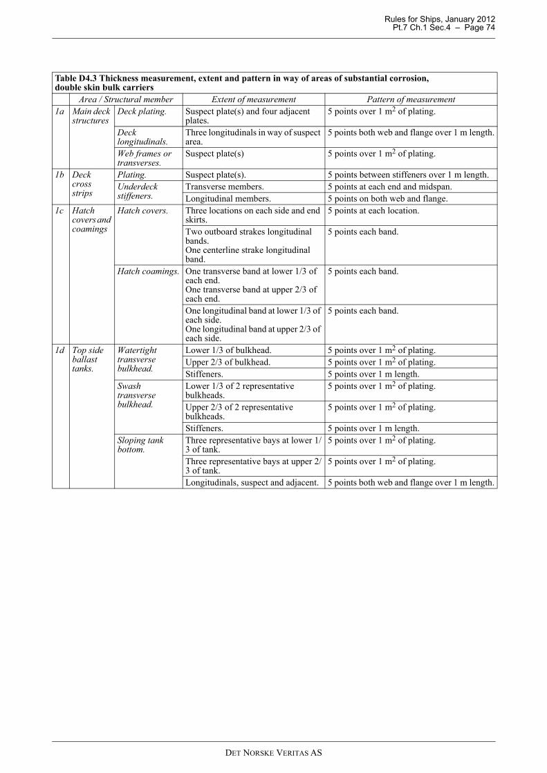
Rules for Ships, January 2012 Pt.7 Ch.1 Sec.4 – Page 74
Table D4.3 Thickness measurement, extent and pattern in way of areas of substantial corrosion, double skin bulk carriers
Area / Structural member Extent of measurement Pattern of measurement1a Main deck
structuresDeck plating. Suspect plate(s) and four adjacent
plates. 5 points over 1 m2 of plating.
Deck longitudinals.
Three longitudinals in way of suspect area.
5 points both web and flange over 1 m length.
Web frames or transverses.
Suspect plate(s) 5 points over 1 m2 of plating.
1b Deck cross strips
Plating. Suspect plate(s). 5 points between stiffeners over 1 m length.Underdeck stiffeners.
Transverse members. 5 points at each end and midspan.Longitudinal members. 5 points on both web and flange.
1c Hatch covers and coamings
Hatch covers. Three locations on each side and end skirts.
5 points at each location.
Two outboard strakes longitudinal bands.One centerline strake longitudinal band.
5 points each band.
Hatch coamings. One transverse band at lower 1/3 of each end.One transverse band at upper 2/3 of each end.
5 points each band.
One longitudinal band at lower 1/3 of each side.One longitudinal band at upper 2/3 of each side.
5 points each band.
1d Top side ballast tanks.
Watertight transverse bulkhead.
Lower 1/3 of bulkhead. 5 points over 1 m2 of plating.Upper 2/3 of bulkhead. 5 points over 1 m2 of plating.Stiffeners. 5 points over 1 m length.
Swash transverse bulkhead.
Lower 1/3 of 2 representative bulkheads.
5 points over 1 m2 of plating.
Upper 2/3 of 2 representative bulkheads.
5 points over 1 m2 of plating.
Stiffeners. 5 points over 1 m length.Sloping tank bottom.
Three representative bays at lower 1/3 of tank.
5 points over 1 m2 of plating.
Three representative bays at upper 2/3 of tank.
5 points over 1 m2 of plating.
Longitudinals, suspect and adjacent. 5 points both web and flange over 1 m length.
DET NORSKE VERITAS AS

Rules for Ships, January 2012 Pt.7 Ch.1 Sec.4 – Page 75
2 Double side structures.
Side shell and inner side plating.
Upper strakes and strakes in way of horizontal girders - minimum three bays along the tank.
1 point each strake and each bay when transverse frames.1 point each panel between pair of longitudinals in each bay.
All other strakes - same three bays as above.
1 point every third panel between pair of longitudinals.
Side shell and inner side frames or longitudinals.
On upper strakes - all frames/ longitudinals in same three bays as above.
3 points across web.1 point on flange.
On all other strakes - one frame or every third longitudinal in same three bays as above.
3 points across web.1 point on flange.
Brackets on side shell and inner side frames or longitudinals.
Minimum of three at top, middle and bottom of tank in same three bays as above.
5 points over area of bracket.
Vertical web frames and transverse bulkheads.
Strakes in way of horizontal girders - minimum two webs and both bulkheads.
5 points over 2 m2 of plating.
Other strakes - minimum two webs and both bulkheads.
2 points between each pair of vertical stiffeners.
Horizontal girders.
Plating on each girder in a minimum of three bays.
2 points between each pair of longitudinal girder stiffeners.
Panel stiffening. Where applicable. 1 point measurements.3 Transvers
e bulkhead structures in cargo holds.
Lower stool. Transverse band within 25 mm of welded connection to inner bottom.
5 points between stiffeners over 1 m length.
Transverse band within 25 mm of welded connection to shelf plate.
5 points between stiffeners over 1 m length.
Bulkhead. Transverse band at approximately mid height
5 points over 1 m2 of plating.
Transverse band adjacent to upper deck or shelf plate of upper stool, whichever is applicable.
5 points over 1 m2 of plating.
Table D4.3 Thickness measurement, extent and pattern in way of areas of substantial corrosion, double skin bulk carriers (Continued)
Area / Structural member Extent of measurement Pattern of measurement
DET NORSKE VERITAS AS

Rules for Ships, January 2012 Pt.7 Ch.1 Sec.4 – Page 76
4 Double bottom and hopper structures.
Bottom, innerbottom and hopper structures plating.
Three bays across double bottom tank, including aft bay.Around and under all suction bell mouths.
5 points each panel between longitudinals and floors.
Bottom, inner bottom and hopper structures longitudinals.
Three - in each bay where bottom plating measured.
3 points in line across web.3 points in line across flange.
Bottom girders, including watertight girders.
At fore and aft watertight floors and in centre of tanks.
1 point between each panel stiffener on girder plating - vertical line of points - minimum three points.
Bottom floors, including watertight floors.
Three - at bays where bottom plating measured, with measurements at both ends and middle.
5 points over 2 m2 of plating.
Web frame rings - hopper structures.
Three - at bays where bottom plating measured, with measurements at both ends and middle.
5 points over 1 m2 of web plating.1 point on flange.
Transverse watertight bulkheads or swash bulkheads - hopper structures.
Lower 1/3 of bulkhead. 5 points over 1 m2 of plating.Upper 2/3 of bulkhead. 5 points over 2 m2 of plating.Three stiffeners. 2 points in line across web at each end.
1 point on web at centre of span.1 point on flange at each end and at centre of span.
Panel stiffening. Where applicable 1 point measurements.Source.: IACS UR Z10.5 TABLE III
Table D4.3 Thickness measurement, extent and pattern in way of areas of substantial corrosion, double skin bulk carriers (Continued)
Area / Structural member Extent of measurement Pattern of measurement
DET NORSKE VERITAS AS
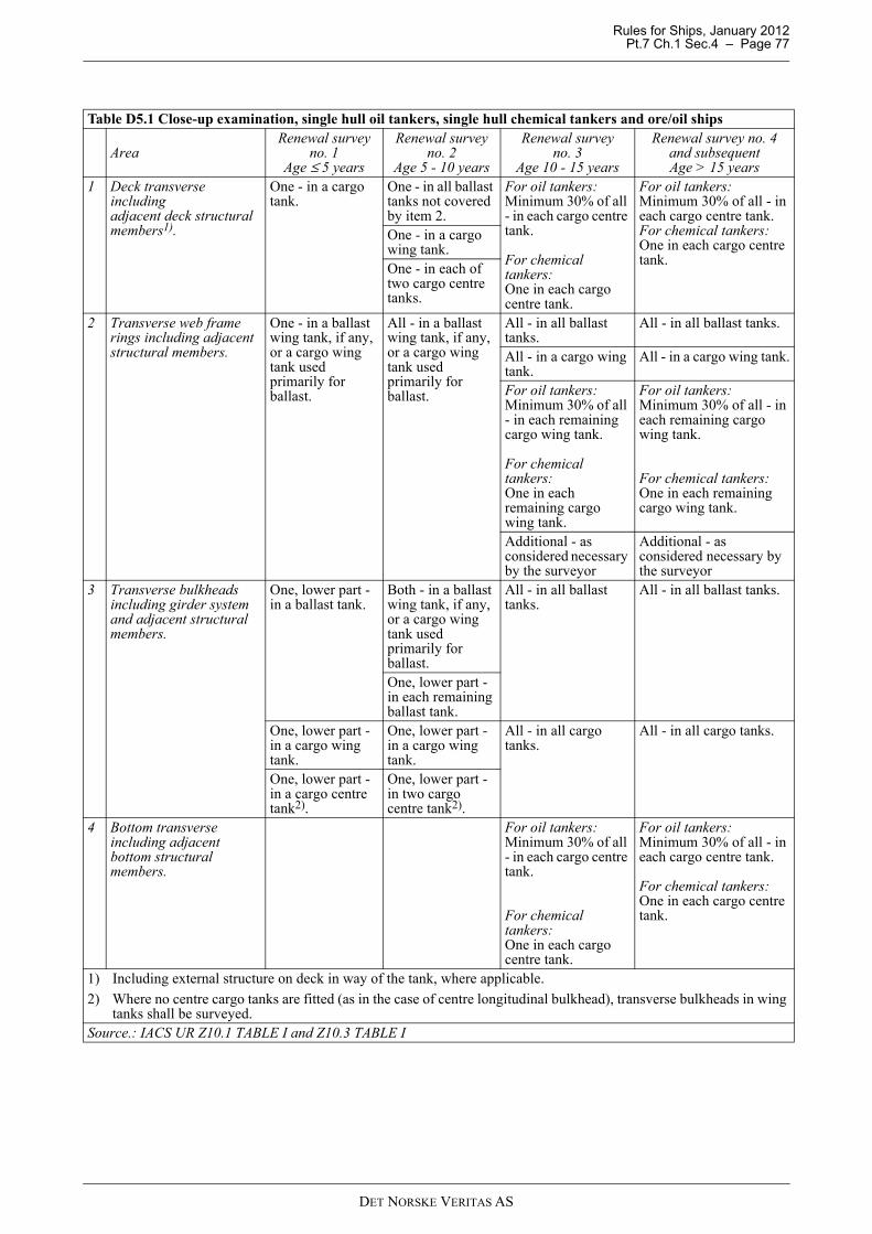
Rules for Ships, January 2012 Pt.7 Ch.1 Sec.4 – Page 77
Table D5.1 Close-up examination, single hull oil tankers, single hull chemical tankers and ore/oil ships
AreaRenewal survey
no. 1Age ≤ 5 years
Renewal survey no. 2
Age 5 - 10 years
Renewal survey no. 3
Age 10 - 15 years
Renewal survey no. 4 and subsequentAge > 15 years
1 Deck transverse including adjacent deck structural members1).
One - in a cargo tank.
One - in all ballast tanks not covered by item 2.
For oil tankers:Minimum 30% of all - in each cargo centre tank.
For chemical tankers:One in each cargo centre tank.
For oil tankers:Minimum 30% of all - in each cargo centre tank.For chemical tankers:One in each cargo centre tank.
One - in a cargo wing tank.One - in each of two cargo centre tanks.
2 Transverse web frame rings including adjacent structural members.
One - in a ballast wing tank, if any, or a cargo wing tank used primarily for ballast.
All - in a ballast wing tank, if any, or a cargo wing tank used primarily for ballast.
All - in all ballast tanks.
All - in all ballast tanks.
All - in a cargo wing tank.
All - in a cargo wing tank.
For oil tankers:Minimum 30% of all - in each remaining cargo wing tank.
For chemical tankers:One in each remaining cargo wing tank.
For oil tankers:Minimum 30% of all - in each remaining cargo wing tank.
For chemical tankers:One in each remaining cargo wing tank.
Additional - as considered necessary by the surveyor
Additional - as considered necessary by the surveyor
3 Transverse bulkheads including girder system and adjacent structural members.
One, lower part - in a ballast tank.
Both - in a ballast wing tank, if any, or a cargo wing tank used primarily for ballast.
All - in all ballast tanks.
All - in all ballast tanks.
One, lower part - in each remaining ballast tank.
One, lower part - in a cargo wing tank.
One, lower part - in a cargo wing tank.
All - in all cargo tanks.
All - in all cargo tanks.
One, lower part - in a cargo centre tank2).
One, lower part - in two cargo centre tank2).
4 Bottom transverse including adjacent bottom structural members.
For oil tankers:Minimum 30% of all - in each cargo centre tank.
For chemical tankers:One in each cargo centre tank.
For oil tankers:Minimum 30% of all - in each cargo centre tank.
For chemical tankers:One in each cargo centre tank.
1) Including external structure on deck in way of the tank, where applicable.
2) Where no centre cargo tanks are fitted (as in the case of centre longitudinal bulkhead), transverse bulkheads in wing tanks shall be surveyed.
Source.: IACS UR Z10.1 TABLE I and Z10.3 TABLE I
DET NORSKE VERITAS AS

Rules for Ships, January 2012 Pt.7 Ch.1 Sec.4 – Page 78
Table D5.2 Minimum thickness measurements1), single hull oil tankers, single hull chemical tankers and ore/oil ships
AreaRenewal survey
no. 1Age ≤ 5 years
Renewal survey no. 2
Age 5 - 10 years
Renewal survey no. 3
Age 10 - 15 years
Renewal survey no. 4 and subsequentAge > 15 years
0a Transverse section(s) within the cargo area. 2)
One section of deck plating only - for the full beam of the ship 3)
One complete section 3)
Two complete sections - at least one within 0.5L amidships 3)
Three complete sections - at least one within 0.5L amidships 3)
0b Structural members subject to close-up examination according to Table D5.1.
Measurements, for general assessment and recording of corrosion pattern.
Measurements, for general assessment and recording of corrosion pattern.
Measurements, for general assessment and recording of corrosion pattern.
Measurements, for general assessment and recording of corrosion pattern.
1 Main deck plating All - within the cargo area.
All - within the cargo area.
All - within the cargo area. All exposed - outside the cargo area.
2 Wind- and water strakes. Selected outside the cargo area.
All - within the cargo area. Selected outside the cargo area.
All - full length.
3 Transverse bulkheads See item 0b See item 0b See item 0b See item 0b4a Keel plates and bottom
plates.All keel plates full length. All bottom plates, including lower turn of bilge, within the cargo area.Additional bottom plates in way of cofferdams, machinery space and aft end of tanks.
4b Sea chests and shell plating in way of overboard discharges.
Plating of sea chests.Shell plating as considered necessary by the attending surveyor.
5 Superstructure deck plating (poop, bridge and forecastle deck).
Representative exposed deck plating.
6 Internals in peak tanks. Forepeak and aftpeak.
Forepeak and aftpeak.
7 Air pipes and ventilators All - on the fore deck (forward quarter length).All exposed air pipes to fuel and lube oil daily service tanks.Selected air pipes and ventilator coamings aft of the forward quarter.
All - on the fore deck (forward quarter length).All exposed air pipes to fuel and lube oil daily service tanks.Selected air pipes and ventilator coamings aft of the forward quarter.
Note:
1) Thickness measurement locations should be selected to provide the best representative sampling of areas likely to be most exposed to corrosion, considering cargo and ballast history and arrangement and condition of protective coatings.
2) Transverse sections shall be chosen where the largest reductions are suspected to occur or are revealed from deck plating measurements.
3) At least one section shall include a ballast tank, within 0.5L amidships, as far as applicable.Source.: IACS UR Z10.1 TABLE II and Z10.3 TABLE II
DET NORSKE VERITAS AS

Rules for Ships, January 2012 Pt.7 Ch.1 Sec.4 – Page 79
Table D5.3 Thickness measurement, extent and pattern in way of areas of substantial corrosion, single hull oil tankers, single hull chemical tankers and ore/oil ships
Area / Structural member Extent of measurement Pattern of measurement1 Deck
structures.Deck plating. Two bands across tank. 3 points per plate per band.Deck longitudinals.
Three longitudinals in each of two bays.
3 points in line vertically on webs.2 points on flange (if fitted).
Longitudinal girders and brackets.
At fore and aft transverse bulkhead, bracket toes and in centre of tanks.
1 point between each panel stiffener on web plating - vertical line of points - minimum three points. 2 points across flange.5 points on girder/ bulkhead brackets.
Transverse girders.
Two - with measurements at both ends and middle.
5 points over 2 m2 of web plating.1 point on flange.
Panel stiffening. Where provided. 1 point measurements.
2 Side shell and longitudinal bulkhead structures.
Shell and bulkhead plating.
On deckhead and bottom strakes - all longitudinals in same three bays as above.
3 points across web.1 point on flange.
On all other strakes - every third longitudinal in same three bays as above.
3 points across web.1 point on flange.
Shell and bulkhead longitudinals.
One transverse band at lower 1/3 of each end.One transverse band at upper 2/3 of each end.
5 points each band.
One longitudinal band at lower 1/3 of each side.One longitudinal band at upper 2/3 of each side.
5 points each band.
Brackets on longitudinals.
Minimum of three at top, middle and bottom of tank in same three bays as above.
5 points over area of bracket.
Web frames and cross ties.
Three webs with minimum of three locations on each web, including in way of cross tie connections.
5 points over about 2 m2 web area.1 point on web frame and cross tie flanges.
3 Transverse bulkhead and swash bulkhead structures.
Plane bulkhead plating.
Deckhead and bottom strakes, and strakes in way of stringer platforms - approximately 1/4, 1/2 and 3/4 width of tank.
5 points between each pair of stiffeners over 1 m length.
All other strakes - at middle width of tank.
1 point between each pair of stiffeners.
Corrugated bulkhead plating.
Strakes for each change of scantling at centre of panel and at flange or fabricated connection.
5 points over 1 m2 of plating.
Stiffeners Three typical stiffeners. 2 points in line across web at each end.1 point on web at centre of span.1 point on flange at each end and at centre of span.
Brackets. Three at top, middle and bottom of tank.
5 points over area of bracket.
Deep webs and girders.
At toe of brackets and at centre of span.
5 points over about 2 m2 web area.3 points across flange.
Stringer platforms.
All - at both ends and middle. 5 points over 1 m2 web area.1 point near bracket toes and on flange.
DET NORSKE VERITAS AS

Rules for Ships, January 2012 Pt.7 Ch.1 Sec.4 – Page 80
4 Bottom structures.
Bottom plating. Three bays across tank, including aft bay.Around and under all suction bell mouths.
5 points each panel between longitudinals and webs.
Bottom longitudinals.
Three longitudinals in each bay where bottom plating measured.
3 points in line across web.3 points in line across flange.
Bottom girders and brackets.
At fore and aft bulkhead bracket toes and in centre of tanks.
1 point between each panel stiffener on web plating - vertical line of points - minimum three points. 2 points across flange5 points on girder/ bulkhead brackets.
Bottom transverse webs.
Three webs at bays where bottom plating measured, with measurements at both ends and middle.
5 points over 2 m2 of plating.
Panel stiffening. Where provided. 1 point measurements.Source.: IACS UR Z10.1 TABLE IV and Z10.3 TABLE IV
Table D5.3 Thickness measurement, extent and pattern in way of areas of substantial corrosion, single hull oil tankers, single hull chemical tankers and ore/oil ships (Continued)
Area / Structural member Extent of measurement Pattern of measurement
DET NORSKE VERITAS AS
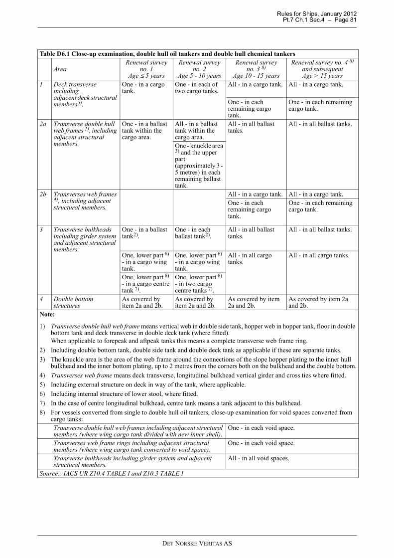
Rules for Ships, January 2012 Pt.7 Ch.1 Sec.4 – Page 81
Table D6.1 Close-up examination, double hull oil tankers and double hull chemical tankers
AreaRenewal survey
no. 1Age ≤ 5 years
Renewal survey no. 2
Age 5 - 10 years
Renewal survey no. 3 8)
Age 10 - 15 years
Renewal survey no. 4 8) and subsequentAge > 15 years
1 Deck transverse including adjacent deck structural members5).
One - in a cargo tank.
One - in each of two cargo tanks.
All - in a cargo tank. All - in a cargo tank.
One - in each remaining cargo tank.
One - in each remaining cargo tank.
2a Transverse double hull web frames 1), including adjacent structural members.
One - in a ballast tank within the cargo area.
All - in a ballast tank within the cargo area.
All - in all ballast tanks.
All - in all ballast tanks.
One - knuckle area 3) and the upper part (approximately 3 - 5 metres) in each remaining ballast tank.
2b Transverses web frames 4), including adjacent structural members.
All - in a cargo tank. All - in a cargo tank.One - in each remaining cargo tank.
One - in each remaining cargo tank.
3 Transverse bulkheads including girder system and adjacent structural members.
One - in a ballast tank2).
One - in each ballast tank2).
All - in all ballast tanks.
All - in all ballast tanks.
One, lower part 6) - in a cargo wing tank.
One, lower part 6) - in a cargo wing tank.
All - in all cargo tanks.
All - in all cargo tanks.
One, lower part 6) - in a cargo centre tank 7).
One, lower part 6) - in two cargo centre tanks 7).
4 Double bottom structures
As covered by item 2a and 2b.
As covered by item 2a and 2b.
As covered by item 2a and 2b.
As covered by item 2a and 2b.
Note:
1) Transverse double hull web frame means vertical web in double side tank, hopper web in hopper tank, floor in double bottom tank and deck transverse in double deck tank (where fitted).When applicable to forepeak and aftpeak tanks this means a complete transverse web frame ring.
2) Including double bottom tank, double side tank and double deck tank as applicable if these are separate tanks.
3) The knuckle area is the area of the web frame around the connections of the slope hopper plating to the inner hull bulkhead and the inner bottom plating, up to 2 metres from the corners both on the bulkhead and the double bottom.
4) Transverses web frame means deck transverse, longitudinal bulkhead vertical girder and cross ties where fitted.
5) Including external structure on deck in way of the tank, where applicable.
6) Including internal structure of lower stool, where fitted.
7) In the case of centre longitudinal bulkhead, centre tank means a tank adjacent to this bulkhead.
8) For vessels converted from single to double hull oil tankers, close-up examination for void spaces converted from cargo tanks:Transverse double hull web frames including adjacent structural members (where wing cargo tank divided with new inner shell).
One - in each void space.
Transverses web frame rings including adjacent structural members (where wing cargo tank converted to void space).
One - in each void space.
Transverse bulkheads including girder system and adjacent structural members.
All - in all void spaces.
Source.: IACS UR Z10.4 TABLE I and Z10.3 TABLE I
DET NORSKE VERITAS AS

Rules for Ships, January 2012 Pt.7 Ch.1 Sec.4 – Page 82
Table D6.2 Minimum thickness measurements1), double hull oil tankers and double hull chemical tankers
AreaRenewal survey
no. 1Age ≤ 5 years
Renewal survey no. 2
Age 5 - 10 years
Renewal survey no. 3
Age 10 - 15 years
Renewal survey no. 4 and subsequentAge > 15 years
0a Transverse section(s) within the cargo area 2)
One section of deck plating only - for the full beam of the ship 3)
One complete section 3)
Two complete sections - at least one within 0.5 L amidships 3)
Three complete sections - at least one within 0.5 L amidships 3)
0b Structural members subject to close-up examination according to Table D6.1.
Measurements, for general assessment and recording of corrosion pattern.
Measurements, for general assessment and recording of corrosion pattern.
Measurements, for general assessment and recording of corrosion pattern.
Measurements, for general assessment and recording of corrosion pattern.
1 Main deck plating All – within the cargo area.
All - within the cargo area.
All - within the cargo area. All exposed - outside the cargo area.
2 Wind- and water strakes.
Selected outside the cargo area.
All - within the cargo area. Selected outside the cargo area.
All - full length.
3 Transverse bulkheads See item 0b See item 0b See item 0b See item 0b4a Keel plates and bottom
plates.All keel plates full length. All bottom plates, including lower turn of bilge, within the cargo area.Additional bottom plates in way of cofferdams, machinery space and aft end of tanks.
4b Sea chests and shell plating in way of overboard discharges.
Plating of sea chests.Shell plating as considered necessary by the attending surveyor.
5 Superstructure deck plating (poop, bridge and forecastle deck).
Representative exposed deck plating.
6 Internals in peak tanks. Forepeak and aftpeak.
Forepeak and aftpeak.
7 Air pipes and ventilators All - on the fore deck (forward quarter length).All exposed air pipes to fuel and lube oil daily service tanks.Selected air pipes and ventilator coamings aft of the forward quarter.
All - on the fore deck (forward quarter length).All exposed air pipes to fuel and lube oil daily service tanks.Selected air pipes and ventilator coamings aft of the forward quarter.
Note:
1) Thickness measurement locations should be selected to provide the best representative sampling of areas likely to be most exposed to corrosion, considering cargo and ballast history and arrangement and condition of protective coatings.
2) Transverse sections shall be chosen where the largest reductions are suspected to occur or are revealed from deck plating measurements.
3) At least one section shall include a ballast tank, within 0.5L amidships, as far as applicable.Source.: IACS UR Z10.4 TABLE II and Z10.3 TABLE II
DET NORSKE VERITAS AS

Rules for Ships, January 2012 Pt.7 Ch.1 Sec.4 – Page 83
Table D6.3 Thickness measurement, extent and pattern in way of areas of substantial corrosion, double hull oil tankers and double hull chemical tankers
Area / Structural member Extent of measurement Pattern of measurement1 Deck
structures.Deck plating. Two bands across tank. 3 points per plate per band.Deck longitudinals.
Every third longitudinal in each of two bands with a minimum of one longitudinal.
3 points in line vertically on webs.2 points on flange (if fitted).
Longitudinal girders and brackets.(usually in cargo tanks only)
At fore and aft transverse bulkhead, bracket toes and in centre of tanks.
1 point between each panel stiffener on web plating - vertical line of points - minimum three points. 2 points across flange.5 points on girder/ bulkhead brackets.
Transverse girders.
Two - with measurements at both ends and middle.
5 points over 2 m2 of web plating.1 point on flange.
Vertical web and transverse bulkhead in wing ballast tank (two metres from deck)
Minimum of two webs, and both transverse bulkheads.
5 points over 1 m2 of plating/ web.
Panel stiffening. Where provided. 1 point measurements.2a Double side
structures.Side shell and inner side plating.
Upper strakes and strakes in way of horizontal girders - minimum three bays along the tank.
1 point each panel between pair of longitudinals in each bay.
All other strakes - same three bays along the tank as above.
1 point every third panel between pair of longitudinals.
Side shell and inner side longitudinals.
On upper strakes - all longitudinals in same three bays along the tank as above.
3 points across web.1 point on flange.
On all other strakes - every third longitudinal in same three bays along the tank as above.
3 points across web.1 point on flange.
Brackets on side shell and inner side longitudinals.
Minimum of three at top, middle and bottom of tank in same three bays along the tank as above.
5 points over area of bracket.
Vertical web frames and transverse bulkheads.
Strakes in way of horizontal girders - minimum two webs and both bulkheads.
5 points over 2 m2 of plating.
Other strakes - minimum two webs and both bulkheads.
2 points between each pair of vertical stiffeners.
Horizontal girders
Plating on each girder in a minimum of three bays.
2 points between each pair of longitudinal girder stiffeners.
Panel stiffening. Where applicable. 1 point measurements.
DET NORSKE VERITAS AS

Rules for Ships, January 2012 Pt.7 Ch.1 Sec.4 – Page 84
2b Longitudinal bulkhead structures (other than inner side longitudinal bulkheads).
Bulkhead plating. Deckhead and bottom strakes, and strakes in way of horizontal girders (also where girders on transverse bulkheads only) – minimum 3 bays along the tank.
1 point each panel between pair of longitudinals.
All other strakes – same three bays as above.
1 point every third panel between pair of longitudinals.
Bulkhead longitudinals.
On deckhead and bottom strakes – all longitudinals in same three bays as above.
3 points across web.1 point on flange.
On all other strakes – every third longitudinal in same three bays as above.
3 points across web.1 point on flange.
Brackets on longitudinals.
Minimum of three at top, middle and bottom of tank in same three bays as above.
5 points over area of bracket.
Web frames and cross ties.
Three webs with minimum of three locations on each web, including in way of cross tie connections.
5 points over about 2 m2 web area.1 point on web frame and cross tie flanges.
3 Transverse bulkhead and swash bulkhead structures in cargo tanks.
Upper and lower stool, where fitted.
Transverse band within 25 mm of welded connection to inner bottom or deck plating.
5 points between stiffeners over 1 m length.
Transverse band within 25 mm of welded connection to shelf plate.
5 points between stiffeners over 1 m length.
Plane bulkhead plating.
Deckhead and bottom strakes, and strakes in way of stringer platforms – approximately ¼, ½ and ¾ width of tank.
5 points each panel between pair of stiffeners over 1 m length.
All other strakes – at middle width of tank.
1 point each panel between pair of stiffeners.
Corrugated bulkhead plating.
Strakes for each change of scantling at centre of panel and at flange or fabricated connection.
5 points over 1 m2 of plating.
Stiffeners Three typical stiffeners. 2 points in line across web at each end.1 point on web at centre of span.1 point on flange at each end and at centre of span.
Brackets. Three at top, middle and bottom of tank.
5 points over area of bracket.
Horizontal girders.
All – at both ends and middle. 5 points over 1 m2 web area.1 point near bracket toes and on flanges.
Table D6.3 Thickness measurement, extent and pattern in way of areas of substantial corrosion, double hull oil tankers and double hull chemical tankers (Continued)
Area / Structural member Extent of measurement Pattern of measurement
DET NORSKE VERITAS AS

Rules for Ships, January 2012 Pt.7 Ch.1 Sec.4 – Page 85
4 Double bottom and hopper structures.
Bottom, inner bottom and hopper structures plating.
Three bays across double bottom tank, including aft bay.Around and under all suction bell mouths.
5 points each panel between longitudinals and floors.
Bottom, inner bottom and hopper structures longitudinals.
Three - in each bay where bottom plating measured.
3 points in line across web.3 points in line across flange.
Bottom girders, including watertight girders.
At fore and aft watertight floors and in centre of tanks.
1 point between each panel stiffener on girder plating - vertical line of points - minimum three points.
Bottom floors, including watertight floors.
Three - at bays where bottom plating measured, with measurements at both ends and middle.
5 points over 2 m2 of plating.
Web frame rings - hopper structures.
Three - at bays where bottom plating measured, with measurements at both ends and middle.
5 points over 1 m2 of web plating.1 point on flange.
Transverse watertight bulkheads or swash bulkheads - hopper structures.
Lower 1/3 of bulkhead. 5 points over 1 m2 of plating.Upper 2/3 of bulkhead. 5 points over 2 m2 of plating.Three stiffeners. 2 points in line across web at each end.
1 point on web at centre of span.1 point on flange at each end and at centre of span.
Panel stiffening. Where applicable 1 point measurements.Source.: IACS UR Z10.4 TABLE IV and Z10.3 TABLE IV
Table D7.1 Close-up examination, liquefied gas tankers
AreaRenewal survey
no. 1Age ≤ 5 years
Renewal survey no. 2 and Age 5 - 10 years
Renewal survey no. 3 and subsequentAge > 10 years
1 Ballast tanks transverse bulkheads, including girder system and adjacent structural members.
One, lower part – in a tank within the cargo area
One in each tank within the cargo area All – in all ballast tanks
2 Ballast tanks transverse web frames, including adjacent structural members.
One in a representative tank of each type within the cargo area
All in a tank, which shall be a double hull side tank or a top side tank. If such tanks are not fitted, another tank shall be selectedOne in each remaining tank within the cargo area
All – in all ballast tanks
Notes:
1) Ballast tank types within the cargo area: top side tank, double hull side tank, hopper side tank, double bottom tank.
2) For ships having independent tanks of type C, with a midship section similar to that of a general cargo ship, the extent of close-up surveys may be specially considered.
Source: IACS UR Z7.2 TABLE I
Table D6.3 Thickness measurement, extent and pattern in way of areas of substantial corrosion, double hull oil tankers and double hull chemical tankers (Continued)
Area / Structural member Extent of measurement Pattern of measurement
DET NORSKE VERITAS AS
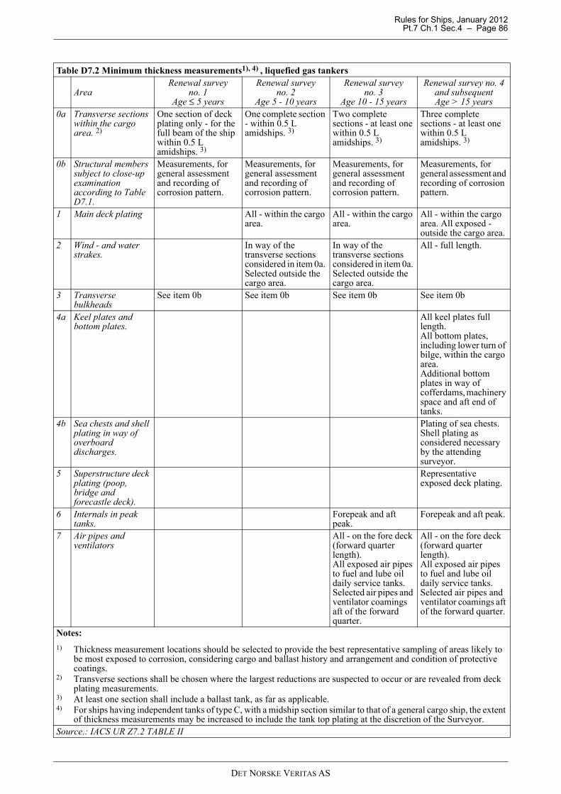
Rules for Ships, January 2012 Pt.7 Ch.1 Sec.4 – Page 86
Table D7.2 Minimum thickness measurements1), 4) , liquefied gas tankers
Area Renewal survey
no. 1Age ≤ 5 years
Renewal survey no. 2
Age 5 - 10 years
Renewal survey no. 3
Age 10 - 15 years
Renewal survey no. 4 and subsequentAge > 15 years
0a Transverse sections within the cargo area. 2)
One section of deck plating only - for the full beam of the ship within 0.5 L amidships. 3)
One complete section - within 0.5 L amidships. 3)
Two complete sections - at least one within 0.5 L amidships. 3)
Three complete sections - at least one within 0.5 L amidships. 3)
0b Structural members subject to close-up examination according to Table D7.1.
Measurements, for general assessment and recording of corrosion pattern.
Measurements, for general assessment and recording of corrosion pattern.
Measurements, for general assessment and recording of corrosion pattern.
Measurements, for general assessment and recording of corrosion pattern.
1 Main deck plating All - within the cargo area.
All - within the cargo area.
All - within the cargo area. All exposed - outside the cargo area.
2 Wind - and water strakes.
In way of the transverse sections considered in item 0a. Selected outside the cargo area.
In way of the transverse sections considered in item 0a. Selected outside the cargo area.
All - full length.
3 Transverse bulkheads
See item 0b See item 0b See item 0b See item 0b
4a Keel plates and bottom plates.
All keel plates full length.All bottom plates, including lower turn of bilge, within the cargo area.Additional bottom plates in way of cofferdams, machinery space and aft end of tanks.
4b Sea chests and shell plating in way of overboard discharges.
Plating of sea chests.Shell plating as considered necessary by the attending surveyor.
5 Superstructure deck plating (poop, bridge and forecastle deck).
Representative exposed deck plating.
6 Internals in peak tanks.
Forepeak and aft peak.
Forepeak and aft peak.
7 Air pipes and ventilators
All - on the fore deck (forward quarter length).All exposed air pipes to fuel and lube oil daily service tanks.Selected air pipes and ventilator coamings aft of the forward quarter.
All - on the fore deck (forward quarter length).All exposed air pipes to fuel and lube oil daily service tanks.Selected air pipes and ventilator coamings aft of the forward quarter.
Notes:
1) Thickness measurement locations should be selected to provide the best representative sampling of areas likely to be most exposed to corrosion, considering cargo and ballast history and arrangement and condition of protective coatings.
2) Transverse sections shall be chosen where the largest reductions are suspected to occur or are revealed from deck plating measurements.
3) At least one section shall include a ballast tank, as far as applicable.4) For ships having independent tanks of type C, with a midship section similar to that of a general cargo ship, the extent
of thickness measurements may be increased to include the tank top plating at the discretion of the Surveyor.Source.: IACS UR Z7.2 TABLE II
DET NORSKE VERITAS AS
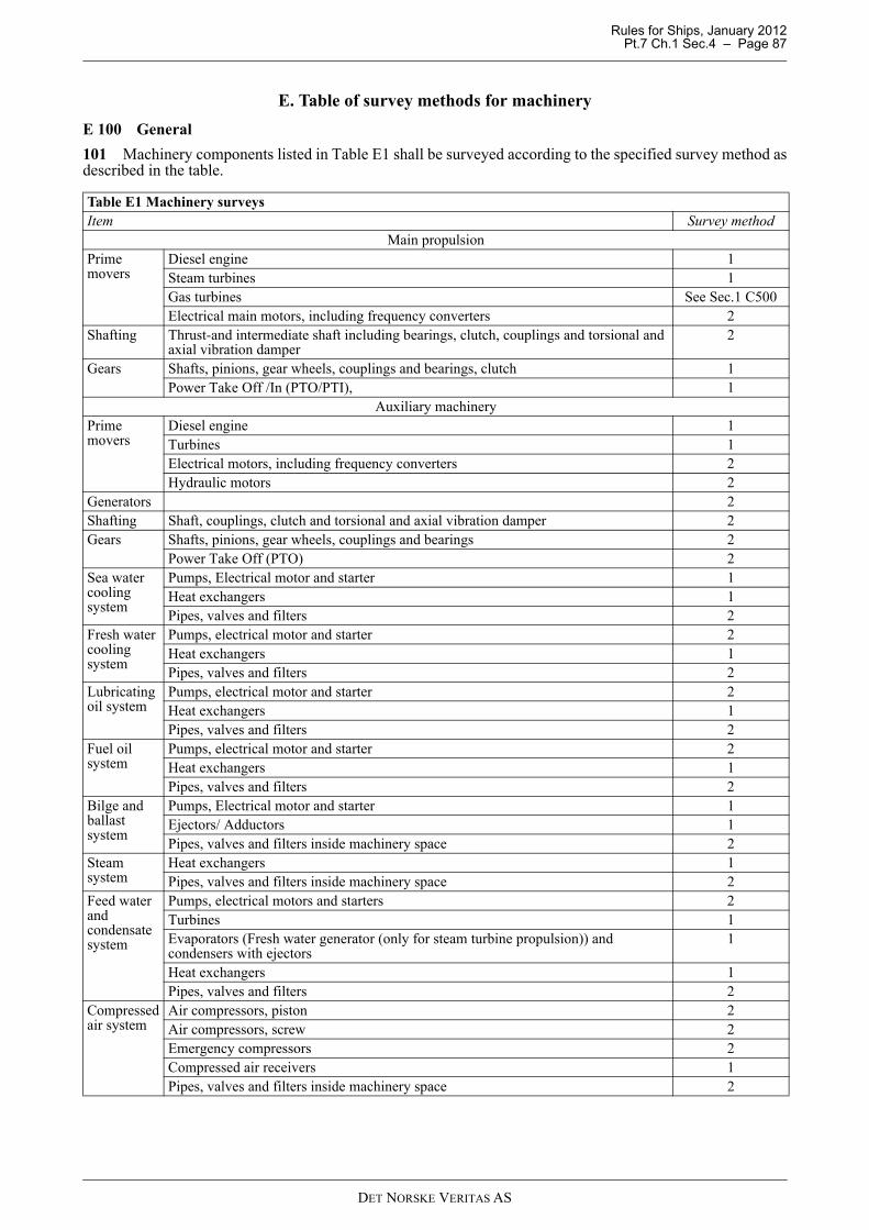
Rules for Ships, January 2012 Pt.7 Ch.1 Sec.4 – Page 87
E. Table of survey methods for machinery
E 100 General
101 Machinery components listed in Table E1 shall be surveyed according to the specified survey method asdescribed in the table.
Table E1 Machinery surveysItem Survey method
Main propulsion Prime movers
Diesel engine 1Steam turbines 1Gas turbines See Sec.1 C500Electrical main motors, including frequency converters 2
Shafting Thrust-and intermediate shaft including bearings, clutch, couplings and torsional and axial vibration damper
2
Gears Shafts, pinions, gear wheels, couplings and bearings, clutch 1Power Take Off /In (PTO/PTI), 1
Auxiliary machineryPrime movers
Diesel engine 1Turbines 1Electrical motors, including frequency converters 2Hydraulic motors 2
Generators 2Shafting Shaft, couplings, clutch and torsional and axial vibration damper 2Gears Shafts, pinions, gear wheels, couplings and bearings 2
Power Take Off (PTO) 2Sea water cooling system
Pumps, Electrical motor and starter 1Heat exchangers 1Pipes, valves and filters 2
Fresh water cooling system
Pumps, electrical motor and starter 2Heat exchangers 1Pipes, valves and filters 2
Lubricating oil system
Pumps, electrical motor and starter 2Heat exchangers 1Pipes, valves and filters 2
Fuel oil system
Pumps, electrical motor and starter 2Heat exchangers 1Pipes, valves and filters 2
Bilge and ballast system
Pumps, Electrical motor and starter 1Ejectors/ Adductors 1Pipes, valves and filters inside machinery space 2
Steam system
Heat exchangers 1Pipes, valves and filters inside machinery space 2
Feed water and condensate system
Pumps, electrical motors and starters 2Turbines 1Evaporators (Fresh water generator (only for steam turbine propulsion)) and condensers with ejectors
1
Heat exchangers 1Pipes, valves and filters 2
Compressed air system
Air compressors, piston 2Air compressors, screw 2Emergency compressors 2Compressed air receivers 1Pipes, valves and filters inside machinery space 2
DET NORSKE VERITAS AS
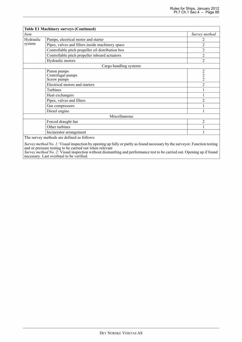
Rules for Ships, January 2012 Pt.7 Ch.1 Sec.4 – Page 88
Hydraulic system
Pumps, electrical motor and starter 2Pipes, valves and filters inside machinery space 2Controllable pitch propeller oil distribution box 2Controllable pitch propeller inboard actuators 2Hydraulic motors 2
Cargo handling systemsPiston pumpsCentrifugal pumpsScrew pumps
222
Electrical motors and starters 2Turbines 1Heat exchangers 1Pipes, valves and filters 2Gas compressors 1Diesel engine 1
Miscellaneous Forced draught fan 2 Other turbines 1 Incinerator arrangement 1
The survey methods are defined as follows:
Survey method No. 1: Visual inspection by opening up fully or partly as found necessary by the surveyor. Function testing and or pressure testing to be carried out when relevant Survey method No. 2: Visual inspection without dismantling and performance test to be carried out. Opening up if found necessary. Last overhaul to be verified.
Table E1 Machinery surveys (Continued)Item Survey method
DET NORSKE VERITAS AS

Rules for Ships, January 2012 Pt.7 Ch.1 Sec.5 – Page 89
SECTION 5 MISCELLANEOUS MAIN CLASS SURVEYS
A. Bottom Surveys
A 100 General
101 Bottom surveys are surveys of the outside of the ship's hull below the deepest load waterline and relateditems.
102 The survey shall include examination of:
— hull plating and stern frame— openings. All sea valves, including scuppers and sanitary discharges, shall be fully or partly opened up and
examined at alternate bottom survey— for ships fitted with box coolers, the coolers shall be withdrawn at alternate bottom survey for examination
of the box cooler space, water cover and top plate, mounting flange with weld connection to the hull,connection bolts and gaskets
— steering fins, shaft brackets and other appendages fitted— rudder with attachments and bearings, see 200— propeller with attachments and propeller shaft external parts, see 300— thrusters, see 400— stabiliser fins.
Guidance note:The survey of stabiliser fins shall include, as far as practicable,examination of:
- fin including tail flap with hinge and link systems as applicable- fin box with watertight boundaries- fin bushes- main seals of the stabiliser.An operational test shall be carried out including mechanical securing devices. At the time of dry docking, NDT shallbe carried out as deemed necessary by the surveyor.
---e-n-d---of---G-u-i-d-a-n-c-e---n-o-t-e---
103 Bottom surveys are normally to be carried out with the ship in dry dock or on a slipway.If the ship is built for in-water survey of the bottom and related items and sea conditions are such that an in-water survey can be satisfactorily carried out, bottom surveys may be permitted while the ship is afloat.
104 At the time of drydocking, the painting of markings required for the class notation BIS shall be checkedand confirmed in order.
105 At the time of drydocking, a dock trial shall be carried out to confirm satisfactory operation of main andauxiliary machinery.
A 200 Rudder with attachments and bearings
201 Visible parts of the following items shall be examined:
— rudder— rudder horn— sole piece— rudderstock and rudder shafts with couplings— rudder pintles and gudgeons.
Dismantling may be required to the extent found necessary by the surveyor.
202 For oil lubricated rudder bearings the sealing arrangement shall be examined for tightness and thebearings shall be checked for wear as far as practicable.For water lubricated rudder bearings the bearing clearances shall be measured.
203 For cone couplings, nuts shall be examined for verifying that all parts are intact and secure.Inspection plates, where fitted, shall be removed.
204 For flange couplings, bolts and nuts shall be examined for verifying that all parts are intact and secure.
205 Areas susceptible to fractures shall be checked by an efficient crack detection method at every docking.Such areas are:
DET NORSKE VERITAS AS
Rules for Ships, January 2012 Pt.7 Ch.1 Sec.5 – Page 90
— weld connections at flanged connection between rudder and rudder stock, in particular for spade rudders— rudder plating in way of abrupt changes in rudder cross section, e.g. at cutout for rudder horn bearing— weld connections in way of removable plate for access to nut on rudder stock, pintle or shaft.
206 For flap rudders, the hinge and link systems shall be examined.Retaining arrangement for hinge pins shall be examined as far as practicable.
A 300 Propeller with attachments
301 The propeller blades, propeller boss and propeller shaft external part shall be examined.Dismantling may be required to the extent found necessary by the surveyor.
Guidance note:If a rope guard is fitted, this shall be of such a construction as to facilitate the inspection of the shafting between thepropeller hub and stern frame box.
---e-n-d---of---G-u-i-d-a-n-c-e---n-o-t-e---
302 The propeller shaft external sealing arrangement and the propeller blade sealing arrangement shall beexamined for tightness.The propeller shaft bearing clearance shall be measured.
303 The following securing arrangements shall be examined for tightness:
— propeller nut— propeller hub coupling bolts or nuts, if bottom survey afloat, only the securing of the protective
arrangement to be examined— propeller blade bolts.
A 400 Thrusters
401 All thrusters shall be externally examined. This comprise examination of gear housing, propeller blades,bolt locking and other fastening arrangements.Dismantling may be required to the extent found necessary by the surveyor.
402 Thrusters for propulsion and thrusters for propulsion and steering shall have the sealing arrangement ofpropeller blades, propeller shaft and steering column examined.
A 500 Bottom survey afloat
501 Every alternate bottom survey may in general be permitted while the ship is afloat for ships with classnotation BIS.For ships which have not been assigned the class notation BIS alternate bottom survey afloat may be permittedprovided the following design conditions are met:
— Rudder bearings shall have synthetic or metallic material. For water lubricated bearings, clearancemeasurements shall be possible while the ship is afloat.
— Propeller shaft bearing and sealing arrangement shall be of such type which does not require propeller shaftwithdrawal carried out in less than 5-years intervals.For water lubricated propeller shaft bearing, clearance measurements shall be possible while the ship isafloat.
— Thrusters/podded thrusters for propulsion and dynamic positioning systems need not have standardmaintenance or examination schedule requiring the ship in dry dock at less than 5-years interval.
In such cases a proposal for in-water survey shall be submitted in advance of the survey confirming that rudder,tailshaft and/ or propulsion thrusters can be satisfactorily examined - as applicable, including the operatinghistory for these components.
502 Bottom surveys afloat may be permitted subject to the following restrictions:
— For general dry cargo ships subject to EHSR (see Sec.1 A Definitions), for liquefied gas tankers and for shipswith class notation ESP the bottom survey in conjunction with the renewal survey must be carried out with theship in dry dock.
— For ships of 15 years of age or over bottom surveys afloat will only be permitted after special consideration.— For ships of 15 years of age or over, with class notation ESP, bottom surveys afloat will not be permitted.
503 The in-water survey shall provide the information obtained from a docking survey. During such surveysthe following conditions shall be satisfactorily fulfilled:
— the water conditions at the location of the survey shall be satisfactory with respect to visibility, current,swell, etc.
DET NORSKE VERITAS AS

Rules for Ships, January 2012 Pt.7 Ch.1 Sec.5 – Page 91
— an approved diving company shall be used in the survey, using pictorial equipment of such quality that thesurveyor is fully satisfied with the information relayed to him
— a diving report shall be presented— location of possible damage to be ascertained— the survey shall be witnessed by a surveyor of the Society.
The removal of inspection plates as given in 203 may be dispensed with if the surveyor is satisfied with thecondition based on:
— examination of visible parts of rudderstock, rudder shafts and pintles with couplings and gudgeons— the measurement of bearing clearances— review of operating history— on board testing as applicable.
504 If the in-water survey reveals damage or deterioration that requires early attention, the surveyor mayrequire that the ship be dry-docked in order that a detailed survey can be undertaken and the necessary repairscarried out.
505 On a case by case basis, and in accordance with CN 72.2, the society may accept a survey schemeallowing two consecutive periodical bottom surveys to be carried out afloat.
B. Propeller Shaft Survey
B 100 General
101 The propeller shaft shall be drawn to permit examination of the shaft and the following parts:
— propeller shaft bearing areas— stern bushes or bearings— shaft sealing arrangement, including lubricating oil system— aft bearing clearances to be measured/calculated and recorded— oil level monitoring of lubricating oil system.
Guidance note:Bearing clearances to be measured or calculated from wear down measurements and clearance from new building orlast shaft withdrawal.
---e-n-d---of---G-u-i-d-a-n-c-e---n-o-t-e---
102 For oil lubricated propeller shafts with type approved sealing glands, the withdrawal of the propellershaft may be exempted at alternate surveys, i.e. extended to 10 years intervals, provided the following itemshave been examined with satisfactory result (Reduced scope):
— new oil seals should be fitted— oil sealing contact surfaces in order— aft bearing clearances measured/calculated and recorded— oil level monitoring of lubricating oil system— oil analysis (not older than 3 months) in order.
Guidance note:Bearing clearances to be measured or calculated from wear down measurements and clearance from new building orlast shaft withdrawal.
---e-n-d---of---G-u-i-d-a-n-c-e---n-o-t-e---
In addition to the above, a propeller connection survey in accordance with C101 shall be carried out forpropeller shafts with a keyway.
Guidance note:The lubricating oil analysis should include the minimum parameters:
- water content- chlorides content (sodium and magnesium)- content of bearing metal particles (iron, aluminium, nickel, chromium, copper, tin, and lead)- content of other particles (silicon)- oil aging, resistance to oxidation (TAN, TBN).Oil sample should be taken under service conditions.
---e-n-d---of---G-u-i-d-a-n-c-e---n-o-t-e---
DET NORSKE VERITAS AS

Rules for Ships, January 2012 Pt.7 Ch.1 Sec.5 – Page 92
C. Propeller Connection Survey
C 100 General
101 For arrangements where the propeller is mounted on a keyed taper the following shall be examined afterthe propeller is backed off:
— propeller shaft threaded end— propeller shaft taper and keyway— propeller hub taper and keyway— key— NDT of fore part of the shaft taper and shaft keyway by an approved crack detection method.
102 For arrangements where the propeller is mounted on a keyless taper, or by means of a cylindrical/conicalsleeve the following shall be examined after the propeller is backed off:
— propeller shaft threaded end— propeller shaft tapered or cylindrical section— propeller hub taper — NDT of the fore part of the shaft taper, or shaft cylinder, by an approved crack detection method.
103 For arrangements where the propeller hub is fitted to a flange coupling or a forged propeller shaft flangethe following shall be examined:
— visual inspection of the flange and its fittings— tightness of bolts or nuts— NDT of the flange fillet radius, by an approved crack detection method, may be required if the visual
examination of the area is not satisfactory.
D. Survey of Geared Thrusters for Main Propulsion and Dynamic Positioning Systems
D 100 General
101 The requirements in this sub-section apply to thrusters for propulsion and thrusters for propulsion andsteering of the ship.
Guidance note:Thrusters installed to achieve redundant main propulsion systems shall be subject to the requirements in this sub-section.
---e-n-d---of---G-u-i-d-a-n-c-e---n-o-t-e---
102 Thrusters for main propulsion and dynamic positioning systems shall be subjected to oil samples atregular intervals of not more that 3 months and analysed by recognized laboratories. The result shall bepresented in a way that makes it is easy to read the trends from the previous analyses. Record of results shallbe available on board at all times.A representative oil sample shall be taken before the filters and with the unit in its normal running condition.Oil analysis shall detect iron (Fe) and other solid contamination in addition to possible water content. The watercontent due to condensation is normally not to exceed 0.5%. The oil analysis shall if applicable cover all of thefollowing areas:
— lubrication oil for gears, bearings— sealing boxes— steering gear— propeller.
If the propeller shafts seal oil systems do not allow for sampling unless the vessel is in dry dock, arepresentative oil analysis shall be taken in connection with the Bottom Survey.
103 Outboard (wet) parts of the thruster accessible from the outside are covered by the bottom surveys.
104 Thrusters for main propulsion and dynamic positioning systems shall be subjected to survey every 5years. The complete survey shall include:
1) evaluation of oil analysis of gear lubrication oil, propeller hydraulic system oil and sealing system oil. See102
2) opening up of protection covers3) inspection of power transmission gear (gear clearance to be measured), bearings (axial play to be
measured), visible parts of shafts and general condition of housing internally.
DET NORSKE VERITAS AS

Rules for Ships, January 2012 Pt.7 Ch.1 Sec.5 – Page 93
4) examination of controllable pitch mechanism oil transmission system and feedback system for wear down anddamage
5) full stroke ahead and astern to be verified and correct blade position feed-back and indication verified6) examination of steering column and related sealing and bearing7) running test at MCR.
Provided that an approved Thruster Condition Monitoring (CM) Survey Arrangement is in place. Ref. Sec.8C300. The scope described from 1) to 7) is covered by the Thruster CM Arrangement, and followed up through annualThruster CM Survey and Bottom Survey.
105 Inboard parts of the thruster accessible from the inside, such as drive motors, shafting system, geartransmissions, pumps and piping systems, alarm, safety and control systems are covered by the main classsurveys of machinery. In addition to geared thrusters this will be applicable for e.g. Voith-Schneider and pumptype thrusters.
106 At each overhaul of the thruster unit the following shall be carried out in the presence of a surveyor tothe Society:
— all relevant parts of the components made accessible during overhaul shall be surveyed using adequatemethods, such as visual inspection MPI or DP, wear down measurements
— NDT for sub-surface cracking of the tooth flanks— MPI shall be carried out of gear teeth and at least in way of stress raisers in the shafts— proper assembly of the thruster shall be verified— proper gear mesh shall be documented in same extent as required for new thruster.
Mounting of the thruster on board shall be verified and function tested.
E. Survey of Podded Thrusters for Main Propulsion and dynamic positioning systems
E 100 General
101 The requirements in this sub-section apply to thrusters of podded design, here after denoted pods, forpropulsion and steering of the ship.
102 Propulsion pod survey implies a survey of the pod's internal power transmission elements and drivingmotor enclosed in the pod, strut and steering column.Pods have two scheduled surveys:
— annual— complete.
For some pod sizes it will be limited access from inside the vessel and annual survey should be done to theextent that is practically possibly. Complete survey might require some dismantling.
103 Parts of the survey may be replaced by an approved condition monitoring arrangement, see ClassificationNote 10.2 Appendix H.
104 At each overhaul, all relevant parts of the components made accessible shall be presented for survey bythe society, see 203.Assembly and mounting on board shall be verified and tested.
E 200 Scheduled surveys
201 Annual surveyScope of the annual pod survey by the society shall include:
— evaluation of lube oil analysis from recognized laboratory (see Sec.5 C101)— survey of functionality and calibration of onboard control and monitoring system (incl. alarm functions if
fitted for continuous monitoring systems)— review of insulation resistance (megger-test) records— maintenance records for various items, such as alarm tests for bilges, bearing inspections, pod inspections,
maintenance of the slip rings electrical connections, etc.— visual inspection of pod motor air cooling system— record of running hours.
DET NORSKE VERITAS AS

Rules for Ships, January 2012 Pt.7 Ch.1 Sec.5 – Page 94
202 Complete surveyThe complete survey shall include:
— same as for annual— examination of drive motor rotor and stator condition and associated equipment, shafts, and stator fixation
arrangement— internal overall survey, check for cleanliness, oil leaks, general condition— verification of seal tightness— verification of bearing condition (e.g. Boroscopic examination to be carried out)— external survey in dry dock, check housing for cracks, corrosion, damage— verification of seals condition (pod/ship)— verify condition of slewing gears and bearing.
203 At overhaul of the thruster unit the following shall be included in addition to the survey requirementsgiven in 202:
— all relevant parts of the components made accessible during overhaul shall be surveyed using adequatemethods, such as visual inspection and MPI or DP, wear down measurements
— MPI shall be carried out in way of stress raisers in the shafts— proper assembly of the thruster shall be verified.
Mounting of the thruster on board shall be verified and function tested.
F. Boiler Survey
F 100 General
101 The requirements in this sub-section applies to all boilers, steam drums, steam generators and/or pipearrangements.Also applicable to steam/thermal oil heated steam generators.
102 Owner's duties prior to survey:
— cleanliness of boiler on both water and gas sides shall be ensured to a condition required to assess structures— boiler to be completely isolated/secured from live steam systems, cooled down and opened up to give
access to both steam/water and fire/gas sides. Hand-hole covers on headers/at bottom of water space shallbe opened up to facilitate internal examination. Boiler armatures shall be readied for opening up
— boiler to be well ventilated on both steam/water and fire side. Safe work lighting to be provided.
103 The survey covers:
— internal examination of the water-steam and fire side, which includes functional testing of safety valvesGuidance note:On small boilers and/or units fitted with steam generating coils / tube panels making internal examination un-practicable, the internal examination may be substituted by hydraulic pressure testing at 1.5 times the design pressure
---e-n-d---of---G-u-i-d-a-n-c-e---n-o-t-e---
— external examination— examination of mountings and fittings, including safety valves, pressure, level and temperature transmitters
for control and monitoring. Opening up as found necessary by the surveyor— review of the following records since the last survey:
- operation- maintenance- repair history- boiler water management.
— verification of the safety valve setting— examination and testing of the operation / function of safety valve relieving gear.
Guidance note:If not possible to circulate steam/hot water through the exhaust gas heated economizer at the time of survey, settingof economizer safety valve(s) may be carried out by the Chief Engineer at sea, and results recorded in the log book.
---e-n-d---of---G-u-i-d-a-n-c-e---n-o-t-e---
For shell type exhaust gas heated economizers, operating in fully flooded condition, the survey will includevisual examination of all accessible welded joints. Crack detection by non destructive testing method as foundnecessary by the surveyor.
DET NORSKE VERITAS AS
Rules for Ships, January 2012 Pt.7 Ch.1 Sec.5 – Page 95
(Ref. IACS UR Z 18)
104 Upon completion of the internal examinations, boilers and steam / thermal oil heated steam generatorsshall be function tested according to the requirements for new installations. Ref. Pt.4 Ch.7 Sec.7 and Pt.6 Ch.3Sec.5 C.The test shall include instrumentation, automatic and remote control equipment, and be witnessed by a DNVsurveyor.
Guidance note:If not possible to raise steam and carry out testing at the time of the internal examination, the following procedureapplies:
- Before surveyed unit is taken into use, safety valves to be set and control, monitoring and safety systems testedunder steam by the Chief Engineer and the results recorded in the log book.
- At the vessel’s next port of call and not later than 45 days from the date of internal examination, the safety valvesetting and control, monitoring and safety systems shall be tested in the presence of a DNV surveyor.
---e-n-d---of---G-u-i-d-a-n-c-e---n-o-t-e---
105 For exhaust boilers fitted with a “bursting disc”, the disc shall be undamaged and comply with theoriginal setting.
106 Soot-cleaning arrangements is subject to visual inspection and function testing. Drainage of cleaningwater shall be in working order.
107 Heaters for main boiler combustion air will be surveyed concurrently with internal boiler examination.For rotary air heaters, the survey will include the satisfactory functioning of exhaust gas and combustion air bypassdampers, and assessment of the fixed fire extinguishing arrangement.
F 200 Damage and repairs to boilers and pressure vessels
201 All damage shall be reported to the Society for assessment.
202 The Society will determine necessary accessibility to ensure that the full extent of the damage isascertained.
203 The following procedure applies:
a) A repair plan shall be discussed with the Society, and concluded.b) The Society will normally supervise execution of repairs at agreed hold-points.c) Repairs shall in general be carried out in such a way that the original design and scantlings are restored. d) Repair work shall be carried out by qualified personnel observing good engineering practices.
204 The requirements in Pt.4 Ch.7 Sec.8 applies to all repair work.
F 300 Emergency repairs
301 To retain the ship’s manoeuvrability, reach safe- or scheduled port, emergency measures/repairs topressure parts may have to be performed without DNV attendance.Information about such emergency measures planned or initiated shall however, always be submitted to DNVwithout delay.Any such repairs are considered temporary measures only, and permanent repairs/ repair solutions shall befinalized prior to further trading.
Guidance note:Repair work may carried out without the attendance of a surveyor (e.g. during voyage), provided the Society isinformed, and a repair plan accepted in advance by the Society.
---e-n-d---of---G-u-i-d-a-n-c-e---n-o-t-e---
302 A DNV surveyor shall be called to survey repairs performed according to 301, when completed.Guidance note:It is for the owner to document to the satisfaction of the attending surveyor that the agreed repair plan has been adhered to.
---e-n-d---of---G-u-i-d-a-n-c-e---n-o-t-e---
F 400 Repairs
401 A repair proposal shall detail:
a) Full extent of damage to be repairedb) Material certification
DET NORSKE VERITAS AS

Rules for Ships, January 2012 Pt.7 Ch.1 Sec.5 – Page 96
c) Certification of consumablesd) Welding procedurese) Welding procedure certificationf) Welders qualification certificationg) Testing schedule.h) Access work, including procedures for “buttering up” (welding up) of material lost when cutting out the
temporary opening.
402 Plugging of boiler tubes initially constitutes a temporary measure only, and shall be reported to theSociety without delay. The extent of plugging and possible acceptance as permanent repair, is subject to assessment by the Society.
403 Cracked steel boiler shell plating, tube plates, corroded welding and pitting shall be repaired throughplate replacement.
404 Heat affected zones of insert welding shall not interfere with heat affected zones of original welding.
405 Longitudinal and circumferential main joints on boiler shells/drums shall be full penetration butt welds. Guidance note:For other than the above circumferential butt welds, see Pt.4 Ch.7 Sec.5 and Sec.8 B201.
---e-n-d---of---G-u-i-d-a-n-c-e---n-o-t-e---
406 Joints shall be welded from both sides of the plates unless otherwise approved.Guidance note:Circumferential joints where dimensions do not allow welding from both sides in headers, pipes and tubes may bewelded from one side only, with or without backing strip.
---e-n-d---of---G-u-i-d-a-n-c-e---n-o-t-e---
407 No attachment shall be welded on in the immediate vicinity of a welded joint. Guidance note:If this cannot be avoided, the welds shall cross or overlap each other completely.
---e-n-d---of---G-u-i-d-a-n-c-e---n-o-t-e---
408 Ends made of welded plates shall be so arranged that they are exposed to the least possible stress. Weldedjoints passing through flanged curvatures shall be at right angles to these.
F 500 Boiler armature/valve replacement
501 Safety valves shall be designed and manufactured according to a recognized standard.Guidance note:Acceptable standard could be e.g. ASME, DIN or equivalent.
---e-n-d---of---G-u-i-d-a-n-c-e---n-o-t-e---
A DNV product certificate is required for valves with D > 100 mm having a design pressure, p > 16 bar. Forother valves, manufacturers’ certificate is acceptable.A DNV material certification is required when operating temperature > 400ºC.
F 600 Post weld heat treatment
601 Pressure vessels including boilers shall be thermally stress relieved after welding when the materialthicknesses at any welded connection exceed 20 mm for any material other than NV1 Cr 0.5Mo and NV 2.25Cr 1 Mo where all thicknesses shall be subject to heat treatment (ref. Pt.4 Ch.7 Sec.8 C100 and Table C1).
Guidance note:Alternatively, if the manufacturer can document that work procedures control or even eliminate formation of unduestresses, the requirement for additional stress relieving may be omitted by the Society.
---e-n-d---of---G-u-i-d-a-n-c-e---n-o-t-e---
F 700 Testing
701 Non-destructive testing shall be carried out as follows:
— All longitudinal butt welded joints in drums, shells and headers subjected to 100% radiographic testing. — 25% of the length of circumferential butt welded joints in drums, shells and headers subjected to
radiographic testing.
DET NORSKE VERITAS AS
Rules for Ships, January 2012 Pt.7 Ch.1 Sec.5 – Page 97
— 10% of the total number of circumferential butt welded joints in pipes and tubes shall be subject toradiographic testing
— For set-in flat plates the cylindrical shell shall be ultrasonically tested for lamellar tearing in way of thecircumferential weld to the flat plate. For shell plate thickness 15 mm and less the extent of testing shall beat least 10% and for greater thickness at least 20% of the total length of the weld. The internal fillet weld,see Fig.8 in Sec.5 to be 100% magnetic particle tested for surface flaws.
— For standpipes and branches with outside diameter exceeding 100 mm, all weld connections to shell andreinforcement rings shall be subjected to magnetic particle testing. For outside diameters 100 mm and less,spot testing is considered a satisfactory extent. The magnetic particle testing shall also cover weld jointsbetween reinforcement rings and shell.
— For furnaces and fireboxes non-destructive testing shall as minimum be carried out as follows, and bewitnessed by a DNV Surveyor:
— 10% of the length of longitudinal butt welded joints subjected to radiographic examination— 10% of the length of circumferential butt welded joints subjected to radiographic examination.— 25% of the length of T-welds and corner welds subjected to ultrasonic examination.
702 Hydraulic pressure testing shall be carried out at 1.5 times the design (calculated) pressure, and bewitnessed by a DNV surveyor.
G. Thermal Oil Heater Survey
G 100 General
101 For thermal oil heaters the following will be assessed:
— tightness of the installation— external condition of coils heated by
- oil or gas burner(s)- exhaust gases
— functional testing of plant instrumentation and safety systems— setting of liquid relief valves.
Guidance note:Safety valves may be set and tested hydraulically in a test bench
---e-n-d---of---G-u-i-d-a-n-c-e---n-o-t-e---
— condition of oil burning equipment— condition of fire extinguishing system— soot blowing arrangements including automatic operation — exhaust gas bypass arrangement — fire fighting arrangement — drainage of fire fighting/cleaning water.
102 Assessment of laboratory analysis report of thermal oil in circulation will be part of the survey.If the laboratory analysis reveals, either:
— chemical degrading of oil in circulation— contamination by low flashpoint petrochemical products— contamination by carbon particles,
one or more of the following actions shall be initiated by the owner, and verified by the Society:
— selected sections of heating coils and/or piping internally examined for accumulation of coke deposits— chemical cleaning of the piping system — circulating pumps opened for examination— oil charge replaced.
G 200 Testing
201 Testing shall be witnessed by a DNV surveyor.
202 Performance testInstrumentation, automatic equipment and remote control systems shall be subjected to testing and verificationthat flow of thermal oil has not been restricted.
DET NORSKE VERITAS AS

Rules for Ships, January 2012 Pt.7 Ch.1 Sec.5 – Page 98
203 Hydraulic pressure testingFor coils in thermal oil installations heated by oil or gas burner(s) or by exhaust, which are not accessible forvisual external inspection, survey may be performed by hydraulic pressure testing 1.5 times the calculatedworking pressure.The test pressure shall be maintained for a period of at least 30 minutes.
DET NORSKE VERITAS AS

Rules for Ships, January 2012 Pt.7 Ch.1 Sec.6 – Page 99
SECTION 6 OPTIONAL CLASS NOTATION SURVEYS
A. Fire Fighting Installations
A 100 General
101 The requirements in this sub-section apply to vessels with class notation:Fire Fighter I orFire Fighter II orFire Fighter III orFire Fighter Capability
A 200 Complete survey (2.5 years)
201 Water spray plant for self protection, including pumps, pipes and nozzles, shall be surveyed and tested.
202 Pumps for water monitors including their prime movers shall be surveyed and tested at maximumcapacity. Remote control of monitors including valve operation shall be tested.
203 Hoses with their equipment shall be surveyed and tested.
204 Firefighters' outfits and compressors for charging the air bottles shall be surveyed.
205 Floodlights shall be tested.
206 It shall be verified that the required operation manual is in order.
207 For ships with class notation Fire Fighter II, or Fire Fighter III or Fire Fighter Capability thesurvey shall include examination of the mobile generator for foam production with its equipment.
208 For ships with class notation Fire Fighter III or Fire Fighter Capability the survey shall includeexamination of the fixed foam monitors with foam production equipment and remote control.
B. Well Stimulation Installations
B 100 General
101 The requirements in this sub-section apply to ships with class notation:Well Stimulation Vessel
102 Survey requirements for installed equipment, systems and features which are generally covered byclassification, are included in the main class surveys.
B 200 Annual survey
201 The flexible high pressure hose including end connectors shall be hydraulically pressure tested to 1.25times its maximum working pressure.
202 The survey shall include examination and testing of:
— emergency remote stop of pumps and shut-off of liquid nitrogen supply valves— tank level gauges— tank level alarms and liquid leakage alarms— hydrogen and oxygen detection and alarm system— hydrogen and oxygen detection and alarm system— decontamination showers and eye washes— personnel protective equipment.
B 300 Complete survey (5 years)
301 Liquid nitrogen tanks shall be inspected internally. On highly stressed parts, non-destructive testing maybe required if considered necessary by the surveyor. The tanks shall be hydrostatically, hydropneumatically orotherwise pressure tested to their MARVS (Maximum Allowable Relief Valve Setting).
302 Acid tanks shall be examined internally.
303 All pressure relief valves shall be opened for survey, adjusted, sealed and function tested.
DET NORSKE VERITAS AS
Rules for Ships, January 2012 Pt.7 Ch.1 Sec.6 – Page 100
304 Pressure/vacuum relief valves for the acid tanks shall be surveyed and tested for proper function.
305 Spot checking by NDT of the high pressure piping shall be carried out.
306 The nitrogen vaporiser shall be opened for internal inspection and hydraulically tested to 1.25 times itsmaximum working pressure after reassembly.
307 The high pressure piping shall be hydraulically tested to 1.25 times its maximum working pressure.
308 The emergency depressurisation and disconnecting of the transfer hose shall be tested.
C. Reception Systems for Recovered Oil
C 100 General
101 The requirements in this sub-section apply to ships with class notation:OILREC
102 Survey requirements for installed equipment, systems and features which are generally covered byclassification, are included in the main class surveys.
C 200 Complete survey (2.5 years)
201 The survey is normally to include examination of the following components and arrangements:
— tanks intended for storage of recovered oil if the tanks are not separated from the engine room bycofferdams
— piping system for oil recovery operations. If recovered oil is led into tanks through hatch openings, theexistence of special hatch covers to prevent gas outflow through the openings shall be verified
— blanking-off arrangements for pipe systems not in use during oil recovery operations— disconnecting arrangements of non-certified electrical equipment in spaces adjacent to tanks for recovered
oil and on open deck— dry powder fire extinguishers including hoses— portable hydrocarbon gas-measuring instrument— electrical equipment certified for use in gas dangerous areas— instruction book for oil recovery operations and signboards.
D. Refrigerated Cargo Plants
D 100 General
101 The requirements in this sub-section apply to ships with class notation:Reefer or RM or RM CONTAINER or KMC or CA or CA (port.)
102 Survey requirements for installed equipment, systems and features which are generally covered byclassification, are included in the main class surveys.
D 200 Annual survey
201 The refrigerating plant, with machinery and equipment, shall be surveyed in running condition,preferably without cargo onboard. Temperature- and capacity control systems as well as alarm and shut-downsystems shall be checked.
202 A tightness test shall be carried out of refrigerant systems with odourless refrigerants. Systems with arefrigerant with distinct odour and brine systems shall be inspected for tightness.
203 The freezing point (density) and acidity (pH value) of the brine shall be checked.
204 Thermometers and other equipment for measuring temperature in holds, chambers, air ducts, RSW tanks,freezing tunnels and plate freezers shall be surveyed and their accuracy checked to the extent found necessaryby the surveyor.
205 CO2 detectors, if required installed, shall be checked.
206 For ships with class notation CA or CA (port.) the survey shall include:
a) examination and testing of the controlled atmosphere installation as follows:
— check that P/V-valves are operational — examination of cleats, hinges, catches and locks for hatches and doors
DET NORSKE VERITAS AS

Rules for Ships, January 2012 Pt.7 Ch.1 Sec.6 – Page 101
— examination of seals and gaskets on hatches and doors — spot check of interlocks on inlet valve arrangement — examination of required ventilation fans during operation — examination of portable ventilators — spot check of N2 release prealarm — spot check of water seals — examination of the N2 generating unit during operation — if arranged, examination of the CO2 scrubber(s) during operation — examination and spot check of gas analysing and monitoring equipment, including fixed equipment,
portable equipment for chamber or space monitoring and portable equipment for personal protection.Calibration records and procedures shall be checked. Use and availability of certified test gases shallbe confirmed
— verification of satisfactory maintenance and function testing procedures for instrumentation. Spotcheck of monitoring, alarm and safety functions
— all signboards on the entrances to rooms adjacent to CA chambers shall be checked. The signboardsshall be in accordance with the approved instruction manual
— locks on doors and hatches to be checked. For number and location of locks, see approved instruction manual.
b) tightness testing with air of all CA chambers or gastight groups of chambers, to the design overpressure.The pressure drop during 15 minutes shall not exceed 30% of the design overpressure. Testing by thevessel's master carried out maximum one month prior to the survey may be accepted based on written reportby the master and provided the visual inspection does not cause doubts about the tightness.
c) verification that the approved instruction manual is onboard, is complete and that the responsible officersare familiar with its content.
D 300 Complete survey (5 years)
301 The refrigerating plant with machinery and equipment shall be tested while cooling down from ambienttemperature to the lowest design temperature for the chambers. The ability to maintain stable delivery airtemperature at all design chamber temperatures shall be demonstrated. Satisfactory operation during defrostingshall be demonstrated.
302 The insulation shall be examined for cold spots when the chambers are at the lowest design temperature.
303 Sufficient areas of insulation shall be stripped from the holds, air trunks, pressure vessels, piping andother insulated parts in order to assess the condition of the insulated steel and the insulation itself.
304 At the second and all subsequent complete surveys pressure vessels with R717 shall be examinedinternally with regard to possible ammonia stress corrosion cracking.
305 Reciprocating compressors may be required opened up for examination, if found necessary by thesurveyor. Screw- and turbo-type compressors may be examined without opening up, provided they are test-runto the surveyor's satisfaction.
306 Air coolers, freezing tunnels and plate freezers shall be examined.
307 Condenser cooling water pumps, brine pumps and RSW pumps shall be opened up and examined.
308 Brine and RSW piping systems shall be examined at working pressure.
309 Water side of water cooled condensers and brine side of brine coolers shall be opened up for examinationof tubes, tube plates and end covers.
310 Pressure gauges, thermometers and automatic controls and alarms shall be tested.
311 Pressure relief valves and safety discs shall be examined externally and on the outlet side afterdismantling of outlet piping and possible external bodies. The tightness over the seat shall be verified. Testingor opening up is required only when specially deemed necessary by the surveyor. Discharge piping shall beexamined with regard to integrity and non-obstructed flow.
312 For ships with class notation CA or CA (port.) the survey shall include:
— examination and testing of the complete controlled atmosphere installation. Air compressors, pressurevessels and other machinery components shall be surveyed in accordance with the principles of the mainclass machinery renewal survey
— tightness testing with air of all CA chambers or gastight groups of chambers, to the design overpressure.The testing shall be carried out in the presence of the surveyor, and the pressure drop during 15 minutesshall not exceed 30% of the design overpressure
— examination of all entrances to CA chambers, through running pipes, hatches and other connections fromadjacent spaces, with respect to corrosion, damaged gaskets and other items which may affect the tightnessbetween CA chambers and adjacent spaces
— testing of gas separating and absorption units, with regard to capacity and quality of the produced gas.
DET NORSKE VERITAS AS

Rules for Ships, January 2012 Pt.7 Ch.1 Sec.6 – Page 102
D 400 Survey in loading port, upon request
401 The Society may upon request carry out surveys of refrigerated cargo installations in the loading port forsuch cargo. Such surveys are not mandatory for retention of class.The chambers shall be examined in an empty state to ascertain that they are clean and free from odour, that thedunnage ribs are in good order, and that no damage has been sustained to the aid ducts, facing or insulation.The surveyor shall ascertain that all pipes for the drainage of the chambers and the drip pans are in goodworking order. The temperatures in the chambers shall be recorded, and the condition of the remotethermometers shall be checked. It shall be ascertained that the plant is free from leakage.
E. Arrangement for Carriage of Dangerous Goods
E 100 General
101 The requirements in this sub-section apply to ships with class notation:DG-P or DG-B
E 200 Complete survey (5 years)
201 These survey requirements are applicable to all types of cargo spaces and classes of dangerous goods.
202 It shall be verified that the following documents are available onboard:
— International Maritime Dangerous Goods Code (IMDG), IMO Res. A.81(IV), as amended.— Relevant sections and the related parts of Appendix B of the Code of Safe Practice for Solid Bulk Cargoes
(BCCode), IMO Res. A.434(XI), as amended.— The IMO/WHO/ILO Medical First Aid Guide for Use in Accidents Involving Dangerous Goods (MFAG),
1982.
203 The following shall be surveyed and tested as applicable:
— electrical installation in cargo spaces— ventilation system for cargo spaces— separate bilge pumping system or drainage for cargo spaces— personnel protective clothing and breathing apparatus— portable fire extinguishers for cargo spaces— insulation of machinery space boundaries— water spray system on open Ro-Ro cargo spaces.
F. Cranes
F 100 General
101 The requirements in this sub-section apply to ships with class notation:Crane Vessel, Crane Barge or CRANE or CRANE(N)
F 200 Annual survey
201 An overall survey shall be carried out with particular emphasis on structural integrity, includingexamination of:
— wire ropes and end attachments— blocks and sheaves— hooks with accessories— shackles— bearings of boom heel and eyebolt connections— securing arrangement for crane during passages.
202 Slewing system (slewing bearing or hook rollers) including tightness of bolts shall be examined as foundnecessary by the surveyor.
203 Examination and functional testing shall be carried out as found necessary by the surveyor for thefollowing:
— correct adjustment of brakes— resistance measurement of electrical systems— leakages in hydraulic system
DET NORSKE VERITAS AS

Rules for Ships, January 2012 Pt.7 Ch.1 Sec.6 – Page 103
— safety devices— emergency stop function— fire extinguisher.
204 It shall be verified that the load charts, marking and components certificates are available and in order.
F 300 Complete survey (5 years)
301 Thickness measurements of structural parts shall be carried out as far as deemed necessary.
302 The following components shall be dismantled (opened up) and/or checked by MPI (magnetic particleinspection):
— boom heel bearings— fixed sheaves— blocks— axle pin and housing— eyebolt connections— hooks, ring and balls.
303 Slewing ring shall be opened up, and internal fillets, raceway and bolts shall be subjected to MPI.Alternatively, if a crane has an approved securing device (retainer) fitted, opening up is not required, but atleast 50% of the holding down bolts shall be drawn and subjected to MPI.
304 Flatness and condition of bearing mounting flanges shall be checked.
305 A load test, as outlined on Form No. CG 2 in the DNV Standard for Certification No. 2.22 “LiftingAppliances”, shall be carried out.
G. Cable Laying Installations
G 100 General
101 The requirements in this sub-section apply to ships with class notation:Cable Laying Vessel/Barge
G 200 Annual survey
201 An overall survey shall be carried out and shall include:
— hydraulic systems— function testing.
G 300 Complete survey (5 years)
301 Bearings and shafts of revolving equipment shall be opened up for examination.
302 Gear wheel and pinions of cable winch shall be checked.
303 Resistance measurements of electrical systems related to cable laying systems shall be carried out.
H. Helicopter Decks
H 100 General
101 The requirements in this sub-section apply to ships with class notation:HELDK
H 200 Complete survey (5 years)
201 The survey required is normally to include examination of the following components and arrangements:
— drainage arrangements— surface protection on wooden decks— safety net— lashing arrangements for the helicopter— arrangement for the prevention of sliding— helicopter deck including supporting structure.
DET NORSKE VERITAS AS
Rules for Ships, January 2012 Pt.7 Ch.1 Sec.6 – Page 104
I. Diving Systems
I 100 General
101 The requirements in this sub-section apply to ships with class notation:DSV-SURFACE or DSV-SAT and Diving systems with class notation -SAT or -SURFACE.
102 The requirements also apply to transferable diving systems, where the regular periodical surveys arecarried out when such systems are in service.When transferable diving systems are out of commission, annual surveys as described in C500 are carried out.
103 Survey requirements by a recognised classification society apply to all diving systems on vessels classedby the Society.
104 A Survey Planning Document shall be part of the documentation on board for the lifetime of the divingsystem.
105 For transferable diving systems, the Survey Planning Document shall specify scope for surveys when thesystem is installed and for surveys when the system is in storage (laid-up).
106 The Survey Planning Document shall be written in English (or translated into English), and approved bythe Society prior to the survey taking place. Checklists shall be included, as attachments.It shall have the following information printed on the front page:
— "DSV Survey Planning Document " (title)— name of support vessel or installation given in the Classification Register— the Society’s identity number given in the Classification Register— IMO number (for statutory surveys)— name of company— revision number and date.
Guidance note:A Survey Planning Document gives owners and surveyors a chance to tailor the instructions to fit each individualsystem or component and thereby avoid misunderstandings often encountered with respect to the application ofgeneric requirements. This may also streamline the surveys in consideration of the operational situations in each case.
---e-n-d---of---G-u-i-d-a-n-c-e---n-o-t-e---
107 Checklists shall be made available for the surveyor to fill out and endorse at each survey. The checklistsshall include the following information at the top of each page:
— name of support vessel or installation given in the Classification Register— the Society’s identity number given in the Classification Register— IMO number (for statutory surveys)— page number— name of company— scope of survey (Annual, Intermediate, Renewal or otherwise)— in columns:
Survey item, Condition, Action, Comment.
I 200 Annual survey
201 The survey is normally to include:
— calibration of essential instrumentation (depth gauges, gas analysers etc.)— switching from main to emergency electrical power supply— emergency systems including bell emergencies (buoyancy if applicable)— functional and power testing of normal and emergency systems of the bell handling system shall be carried
out with a load of at least 1.25 times the working weight in the most unfavourable position— partly dismounting of heat protection and penetrators on the bell may be required.
Detailed specification of test requirements are given in the relevant sections of DNV-OSS-305 "Rules forCertification and Verification of Diving Systems" and the accompanying standard DNV-OS-E402 "OffshoreStandard for Diving Systems".
I 300 Intermediate survey
301 The following tests shall be carried out:
— gas leak tests— testing of safety valves
DET NORSKE VERITAS AS

Rules for Ships, January 2012 Pt.7 Ch.1 Sec.6 – Page 105
— functional test of fire detection-, alarm- and extinction systems— functional tests of life support systems— functional tests of alarm systems— functional tests of mechanical and electrical systems.
I 400 Complete survey (5 years)
401 Bell buoyancy materials, heat protection, penetrators, windows and attached members shall bedismounted for inspection for possible corrosion and deterioration.
402 Pressure tests and inspections shall be carried out according to an approved procedure given as part ofthe Survey Planning Document, and following the principles given in items 406 and 407.Test pressure shall be stamped on the pressure vessels according to the design code or, in the case of weldedpressure vessels, engraved on an attached tag.Applicable codes, standards and regional requirements shall be specified in the procedure.Pressure testing shall be carried out according to the design code of the pressure vessel and to internationalstandards for such testing.The test pressure shall be as stamped on the pressure vessel and given in the accompanying certificate.
Guidance note:International testing standards include EN 1968 "Transportable gas cylinders - Periodic inspection and testing ofseamless steel gas cylinders". The applicable working pressure and corresponding filling ratios should meet the requirements in BS5355 "Fillingratios and developed pressures for liquefiable and permanent gases" or equivalent standard.Regional requirements may also apply, such as the HSE Approved Specification Number CP1-3T "Specification forLarge seamless steel (897 to 1069 N/mm2) Transportable Gas Containers" or Code of Federal Regulations Title 49Ch.I Part 178 Subpart C Sec.178.45 "Specification 3T seamless steel cylinder". (CITE: 49CFR178.45 US DOT).
---e-n-d---of---G-u-i-d-a-n-c-e---n-o-t-e---
403 Proof test or volumetric expansion test shall be carried out according to that which is required by thedesign code or regional requirements.
404 Downgrading of chambers may be requested either:
— to carry out periodical pressure testing after ten years pneumatically at a reduced pressure, or— after installation of view-ports with a lower design pressure than the chamber, or— after any other causes which do not imply a reduction of strength of the pressure vessel.
The procedure necessitates re-stamping of the pressure vessel, and issue of Memo to Owners (MO). The MOshall include the necessary information with respect to:
— the new maximum operating pressure of the diving system, and— the reasons behind the downgrading.
405 Pneumatic testing shall not be carried out at pressures above the design working pressure.
406 At 1st Complete survey the interval for hydraulic pressure testing of gas containers may be extended to10 years if the following principles are applied:
— External and internal survey by intrascope.— If internal survey is not possible or if corrosion or other items of concern are found, hydraulic test shall be
carried out to the test pressure determined by the design code.
At all subsequent Complete periodical surveys:
— External and internal survey by intrascope.— Hydraulic test to the test pressure determined by the design code.
407 At 1st Complete survey the interval for hydraulic pressure testing of bell and chambers may be extendedto 10 years if the following principles are applied:
— External and internal survey.— If internal survey is not entirely possible or if corrosion or other items of concern are found, hydraulic test
shall be carried out to the test pressure determined by the design code.— Alternatively, pneumatic test to the working pressure may be carried out and the pressure vessel down graded,
see 404
At all subsequent Complete periodical surveys:
— External and internal survey.
DET NORSKE VERITAS AS

Rules for Ships, January 2012 Pt.7 Ch.1 Sec.6 – Page 106
— Hydraulic test to the test pressure determined by the design code.— Alternatively, pneumatic test to the working pressure may be carried out and the pressure vessel down graded,
see 404
408 The working weight of the bell shall be checked.
409 A test of the bell handling system with a static load equal to the design load shall be carried out.
410 If applicable the bell's releasable ballast system with attachments shall be structurally tested with a staticload 1.5 times the weight of the ballast in air.
411 Viewports with an age of 10 years or more shall be changed unless a special survey warrants anextension.The special survey shall be carried out to a procedure approved by the Society in accordance with ASMEPVHO-2-2002 "In-Service Guidelines for PVHO acrylic windows".
I 500 Survey of diving systems 'out of commission'
501 Diving systems which have been out of commission, i.e. laid up, for a period normally of at least 12months, shall be surveyed and tested before re-entering service. The extent of the surveys and tests will beconsidered in each case depending upon:
— the time the diving system has been out of commission— the maintenance and preservative measures taken during lay-up— the extent of surveys carried out during this time.
As a minimum, a sea trial for function testing of the diving system shall be carried out.
502 During lay-up, diving system shall be subjected to a lay-up survey on an annual basis.The extent of the lay-up survey is reduced compared to the regular annual survey, but shall cover systemintegrity, planned maintenance system, fire protection and equipment in use.
503 If the lay-up period is more than 12 months, other periodical surveys may be postponed, depending onthe maintenance and preservative measures taken during lay-up.
J. De-icing or Anti-icing Systems
J 100 General
101 The requirements in this sub-section apply to ships with class notation:DEICE or DEICE-C
J 200 Annual survey
201 Visual inspection of anti-icing and de-icing switchboards and confirm heating load on each circuitaccording to marking on the switchboards.
202 Examination of equipment for de-icing and anti-icing including:
— heaters— covers— equipment for manual de-icing— radar equipment— heating coils— steam tracing lines.
K. Additional Fire Protection Arrangements
K 100 General
101 The requirements in this sub-section apply to ships with class notation:F-A or F-M or F-C or F-AM or F-AC or F-MC or F-AMC
102 For ships with the previously given class notation:F the requirements are applicable as far as they are relevant.
DET NORSKE VERITAS AS

Rules for Ships, January 2012 Pt.7 Ch.1 Sec.6 – Page 107
K 200 Complete survey (2.5 years)
201 Fire pumps including emergency fire pump and prime movers shall be examined and tested.
202 Firefighters’ outfits and compressors for charging of air bottles shall be examined.
203 For ships with class notation including the letter A (for accommodation spaces) the survey shall include:
— examination of fire retarding partitions in the accommodation— examination and testing of automatic fire-detecting and alarm systems including release arrangement for
self-closing doors in passageways, stairways and machinery casings— examination of hose stations in the accommodation together with their equipment.
204 For ships with class notation F-M the survey shall include:
— examination and test of main and local extinguishing systems in engine and boiler rooms includingdetection and alarm arrangements. The quantity of extinguishing medium shall be checked
— survey of portable dry powder fire extinguishers and spare charges— survey of hose stations in the engine and boiler rooms together with their equipment— review of the report resulting from the annual “infrared scanning”.
Guidance note:An infrared scanning of all engines and similar equipment shall be carried out on an annual basis - as prescribed inPt.6 Ch.4 Sec.3.
---e-n-d---of---G-u-i-d-a-n-c-e---n-o-t-e---
L. Dynamic Positioning Systems
L 100 General
101 These rules do not include verification of requirements or recommendations in regard to the vesselsoperation or other characteristics.
102 The owner shall advise the Society of major alterations to the DP system hardware or software.The owner may, however, assign the task of advising the Society to a responsible body, representing the owner,e.g. the manufacturer.The Society will consider the need for documentation, re-survey or test.
Guidance note:In addition to renewal of the DP controller hardware or software, a major alteration might also be:
— installation of a new position reference system or other sensor interfaced to the DP-control system— installation of new thrusters— software changes— structural changes— changes in power system.
---e-n-d---of---G-u-i-d-a-n-c-e---n-o-t-e---
103 The requirements in this sub-section apply to ships with class notations for dynamic positioning systems.This being DYNPOS-AUTS or DYNPOS-AUT or DYNPOS-AUTR or DYNPOS-AUTRO or DPS 0 orDPS 1 or DPS 2 or DPS 3, and to ships with previous corresponding class notations.
104 The requirements in sub-sections L400 and L500 apply to ships with class notation:DPS 0, or DPS 1, or DPS 2, or DPS 3.
105 For vessels with qualifier (A) given as:DYNPOS-AUTR(A) or DYNPOS-AUTRO(A) or DPS 2(A) or DPS 3(A) notations, also the annual survey shall be carried out in accordance with the requirement for complete survey,as given in L300 or L500 as applicable.
DET NORSKE VERITAS AS

Rules for Ships, January 2012 Pt.7 Ch.1 Sec.6 – Page 108
106 For class notations with the qualifier (A) an updated FMEA report with a corresponding FMEA testprogram shall be kept onboard, and shall be used as basis for the testing.
L 200 Annual survey
201 System maintenance documentation, including information regarding hardware and software changes,shall be reviewed.
Guidance note:This requirement includes, in addition to the DP-control system, the joystick control system and other systemsnecessary for performing position keeping, e.g. thruster control system.
---e-n-d---of---G-u-i-d-a-n-c-e---n-o-t-e---
202 The electrical installation in excess of the main class requirements shall be visually inspected, i.e.installations comprising the DP system, e.g. controllers and operating stations for DP and independent joystick,references systems, sensors and mode change system.
203 The technical condition of the DP system shall be verified during the survey.Guidance note 1:Verification of the technical condition of the DP system denotes testing to verify that the DP system is capable ofpositioning the vessel, and thus validating that system functionality is in place.
---e-n-d---of---G-u-i-d-a-n-c-e---n-o-t-e---
Guidance note 2:Testing should preferably be done during a sea trial. However, in the case where this is inconvenient (e.g. the vesselis in the middle of a long term operation) the survey may be performed during regular operations. This may imply thatit may not be possible to test all different operational modes.
---e-n-d---of---G-u-i-d-a-n-c-e---n-o-t-e---
204 If the survey is carried out when the vessel is undergoing regular operations, then tests that possibly canintroduce unacceptable risks shall not be performed.
205 Capacity of UPSs and other battery systems serving the DP-control system, including its peripherals,shall be verified. The alarm for loss of charging power shall be verified.
Guidance note:If the survey is carried out during regular operations, then the capacity of the batteries need not be proven by testing.
---e-n-d---of---G-u-i-d-a-n-c-e---n-o-t-e---
206 For class notation DYNPOS-AUTRO, normal working condition of the back-up DP-control systemshall be verified.
Guidance note:If the survey is carried out during regular operations, then control need not be transferred to the back-up DP-controlsystem.
---e-n-d---of---G-u-i-d-a-n-c-e---n-o-t-e---
207 Emergency stop of thrusters from the DP-control centre shall be tested. If the survey is carried out whenthe vessel is undergoing regular operations, then testing shall not be performed if there is any possibility ofintroducing unacceptable risks.
L 300 Complete survey (5 years)
301 With the vessel in DP mode, a sea trial shall be performed.
302 The complete system shall be tested in all operational modes. The testing shall include simulation ofdifferent failure conditions to verify switching of modes, back-up systems and the alarm system.
303 The different modes of thruster control from the DP control centre(s) shall be tested:
— manual control— joystick control (independent joystick, if installed)— DP control— transfer of control.
Manual override i.e. by thruster lever control and independent joystick control shall be demonstrated duringnormal operation and during failure conditions.
304 Emergency stop of DP thrusters from DP-control centre to be tested.
305 All sensors, peripheral equipment and reference systems shall be tested:
DET NORSKE VERITAS AS

Rules for Ships, January 2012 Pt.7 Ch.1 Sec.6 – Page 109
— verify correct operation and adequate accuracy— failure of sensors and reference systems shall be simulated to check the alarm system and the switching
logic— switch-over between reference systems as input to controller shall be carried out to assure that warnings,
alarms and information to operator are satisfactory.
Guidance note 1:Due to practicalities some reference systems may be unavailable during the tests. In such cases the testing can beperformed by the crew as soon as possible after survey. When testing is left to the crew this must be recorded in thesurvey report, and a condition of class or memo to owner must be issued. The condition of class or memo to ownercan be deleted based on a signed test report from the master.
---e-n-d---of---G-u-i-d-a-n-c-e---n-o-t-e---
Guidance note 2:The survey of the thruster unit shall be carried out as for thrusters for propulsion and DP, see Sec.5 C. Surveys of thethrusters are separate survey elements and these surveys do not need to take place at the same time as the DP survey.
---e-n-d---of---G-u-i-d-a-n-c-e---n-o-t-e---
306 Alarm for loss of position and heading out of limit shall be demonstrated.
307 The electrical installation in excess of the main class requirements, shall be visually inspected, i.e.installations comprising the DP system, e.g. controllers and operating stations for DP and independent joystick,references systems, sensors and mode change system.
308 Single failures in thruster control systems including signal wire breaks of thruster command andfeedback signals shall be tested in order to verify safe response on the thrust output. Equivalent testing mayalso be required for rudders controlled by the DP-control system.
309 Overload prevention shall be tested. Guidance note:If it is possible to induce overload by setting out thrust command from the DP-control system (e.g. by use of joystickfunction) then the overload protection function (e.g. pitch reduction) shall be tested.System configuration and/or available power considerations may lead to this test being omitted.
---e-n-d---of---G-u-i-d-a-n-c-e---n-o-t-e---
310 Capacity of UPSs and other battery systems serving the DP-control system including it peripherals shallbe verified by testing. Alarm for loss of charging power shall also be verified.
311 For class notations DYNPOS-AUTR and DYNPOS-AUTRO the required redundancy with respect todefined single failures modes shall be verified by redundancy testing.
312 For class notations DYNPOS-AUTR and DYNPOS-AUTRO the FMEA report and FMEA testprogram shall be verified to ensure that they have been updated when alterations have been done.
Guidance note:This requirement is only valid for vessels with class request after 1. July 2004.
---e-n-d---of---G-u-i-d-a-n-c-e---n-o-t-e---
313 For class notations DYNPOS-AUTR and DYNPOS-AUTRO correct functioning of the ConsequenceAnalysis facility shall be verified as far as possible.
314 For class notation DYNPOS-AUTRO testing shall also be performed on the back-up DP-control system.Switchover to back-up shall be tested, and monitoring of back-up control system status on the main controlsystem shall be verified.
L 400 Annual survey
401 A survey covering the scope described in L200 shall be carried out.Guidance note 1:DPS 0 shall follow the scope for DYNPOS-AUTS, DPS 1 shall follow the scope for DYNPOS-AUT, DPS 2 shall follow the scope for DYNPOS-AUTR,and DPS 3 shall follow the scope for DYNPOS-AUTRO, as far as possible.
---e-n-d---of---G-u-i-d-a-n-c-e---n-o-t-e---
Guidance note 2:Class entry vessels coming from other class societies with class notation:DPS 0, or
DET NORSKE VERITAS AS

Rules for Ships, January 2012 Pt.7 Ch.1 Sec.6 – Page 110
DPS 1, or DPS 2, or DPS 3, may have deviations from Pt.6 Ch.7, see also L202 above.
---e-n-d---of---G-u-i-d-a-n-c-e---n-o-t-e---
L 500 Complete survey (5 years)
501 A survey covering the scope described in L300 shall be carried outGuidance note 1:DPS 0 shall follow the scope for DYNPOS-AUTS, DPS 1 shall follow the scope for DYNPOS-AUT, DPS 2 shall follow the scope for DYNPOS-AUTR,and DPS 3 shall follow the scope for DYNPOS-AUTRO, as far as possible.
---e-n-d---of---G-u-i-d-a-n-c-e---n-o-t-e---
Guidance note 2:Class entry vessels coming from other class societies with class notation DPS 0, or DPS 1, or DPS 2, or DPS 3, may have deviations from Pt.6 Ch.7, which may make some of the items listed in L301-L314, inapplicable.
---e-n-d---of---G-u-i-d-a-n-c-e---n-o-t-e---
M. Nautical Safety
M 100 General
101 The requirements in this sub-section apply to vessels with class notation:
— NAUT including qualifiers AW, OC, OSV(A), OSV(T), NAVY, Q, A, B and C— W1 including qualifiers OC and Q— NAV-O, item 201 only.
M 200 Annual survey
201 Navigation related requirements of the Cargo Ship Safety Equipment Annual Survey shall be performed.
202 The functional status of the navigational equipment shall be verified, including information of anychanges to software and hardware which have been logged.
203 For software and/or hardware changes of the Integrated Navigation System (e.g. comprising trackcontrol system or heading control), a sea trial to verify system performance may by required.
204 For vessels with qualifier Q, the qualification assurance system, operational procedures and certificatesof competence shall be examined to verify compliance with Pt.6 Ch.8 Sec.9.
M 300 Complete survey (5 years)
301 The function of navigation bridge equipment shall be verified:
— adjustable lights in instruments and at workstations— temperature and ventilation control systems— de-misting and de-icing systems, if provided— fresh water window washing systems— window wipers— sunscreens— lighting, white and red.
DET NORSKE VERITAS AS
Rules for Ships, January 2012 Pt.7 Ch.1 Sec.6 – Page 111
302 The bridge alarm management system shall be tested for:
— automatic reset of monitoring system (only for qualifiers OSV(A) and OSV(T))— release of transfer alarm.
The central alarm panel shall be tested for transfer of non-acknowledged alarms and warnings relating to:
— cross track distance (XTD)— automatic radar plotting aid (ARPA).
The automatic radar plotting aid (ARPA) shall be tested for the time to the closest point of approach (TCPA)alarm.The function shall be verified for:
— track control system, if installed.
303 For vessels with qualifier AW or class notation W1, the survey shall include:
— function verification of the grounding avoidance system (GAS)— examination of documentation or poster providing information on the vessel's manoeuvring characteristics— examination of the contents of the manoeuvring booklet— testing of the conning information display (also for qualifier NAVY)— verification of chart radar function (also for qualifiers OSV(A) or OSV(T)).
N. Hull Monitoring Systems
N 100 General
101 The requirements in this sub-section apply to ships with class notation:HMON(...)
N 200 Annual survey
201 The following documents shall be present:
— user/operational manual for the system— maintenance manual— maintenance record (if applicable)— calibration record for sensors.
Guidance note:A yearly calibration of the sensors is required. The calibration may be carried of by the crew.
---e-n-d---of---G-u-i-d-a-n-c-e---n-o-t-e---
202 The inspection of the hull monitoring system shall include verification of the following:
— that all dedicated HMON(...) sensors are functioning (visual inspection of display)— that all connections to ship systems are functioning (visual inspection of display)— that the UPS can power the system for at least 10 minutes— that the deviation between the measured global still water bending moments (stresses) and global moments
calculated by loading computer is within 5% of maximum permitted moments (stresses), and— run the self-check procedure for the system, if applicable.
Guidance note:Typical ship systems connected to the hull monitoring system are loading computer, GPS, speed log and gyro.
---e-n-d---of---G-u-i-d-a-n-c-e---n-o-t-e---
Guidance note:If data from the loading computer is not available for the present condition, historical data from last month may beused.
---e-n-d---of---G-u-i-d-a-n-c-e---n-o-t-e---
DET NORSKE VERITAS AS

Rules for Ships, January 2012 Pt.7 Ch.1 Sec.6 – Page 112
O. Vapour Control Systems
O 100 General
101 The requirements in this sub-section apply to ships with class notation:VCS-1 or VCS-1B or VCS-2 or VCS-2B or VCS-3
102 Survey requirements for the optional class notations:VCS-1, VCS-2 and VCS-3are partly covered by the main class requirements for tankers for oil and chemicals.
O 200 Complete survey (5 years)
201 The survey shall include:
— internal examination of deck tank for liquefied gas, if fitted, including piping, valves etc. and includingNDT and thickness measurement as found necessary
— external examination and tightness testing of deck tank.
At the 2nd and 4th complete survey, and thereafter at each complete survey deck tanks shall be strength testedas specified in Sec.4 B508.
— examination, testing and sealing of deck tank safety relief valves— examination and testing of cooling machinery and equipment.
202 For ships with class notation VCS-1B and VCS-2B the survey shall include examination and testing ofthe following instruments and equipment:
— the means to inert the vapour transfer hose— oxygen analyser with alarms— detonation arrester.
P. Clean Ships
P 100 General
101 The requirements in this sub-section apply to ships with class notation:CLEAN or CLEAN DESIGN
P 200 Annual survey
201 The basic requirement is that the vessel holds a valid international pollution prevention certificate.For the oil pollution prevention certificate, the following shall be checked onboard during survey:
— certificates for type approved oily water separating or filtering equipment, process unit and oil contentmeters
— oil record book entries— approved SOPEP manual— means of control of sludge— standard discharge connection.
Additionally, the following shall be examined and tested, as applicable:
— oil filtering equipment (15 ppm) and process unit with alarm— automatic stopping device (15 ppm)— separation of oil fuel and water ballast system— sludge tank and discharge arrangement externally.
202 In addition the following shall be checked or verified as applicable:
— all refrigerant consumption figures— consumption figures for fire fighting substances with global warming potential (GWP) > 0— garbage record book— oil record books and cargo record book— fuel oil log— NOx emission control equipment log, where applicable— ballast water management log— documentation of antifouling used during dry-dockings since last review.
DET NORSKE VERITAS AS

Rules for Ships, January 2012 Pt.7 Ch.1 Sec.6 – Page 113
Q. Tailshaft Monitoring
Q 100 General
101 The requirements in this sub-section apply to ships with class notation TMON.
102 A tailshaft condition monitoring arrangement (class notation TMON) will be granted for oil lubricatedtailshafts that are monitored to ascertain the condition of the tailshaft system during operation, and that fulfilsthe design requirements in Pt.4 Ch.4 Sec.1 E300 provided a successful initial survey is carried out.In such cases the Society will not require any specific time interval between propeller shaft withdrawal surveys.
103 Ships with more than 3 years since the last propeller shaft withdrawal are normally to carry out apropeller shaft survey as described in Sec.5 B in connection with the TMON initial survey.
Guidance note:The requirement for a propeller shaft withdrawal at TMON initial survey may be waived on a case by case basis,provided that documentation showing satisfactory condition of the stern tube arrangement is presented to the Society.Such documentation, normally covering the last 3 years, should include:
- monthly measurements of stern tube bearing temperatures with corresponding sea water temperatures, oilconsumption, water content in oil
- bearing clearances from new building and last dry docking and clearances calculated from wear downmeasurements since new building shall be presented, where available
- lub. oil analysis reports from accredited laboratory with conclusion, where available (ref. Q301 d).
---e-n-d---of---G-u-i-d-a-n-c-e---n-o-t-e---
Q 200 Initial survey
201 The survey shall include:
— verification of correct readings of remote thermometers for stern tube bearing, seawater and alarm set point— low level alarm for lubricating oil gravity tank and sealing gravity tanks to be tested— a general survey of shafting and sealing arrangement shall be carried out— verification that the oil sampling point is identified with signboard— verification that a written procedure for taking representative oil samples is present onboard— verification that electric grounding device is fitted on the propeller shaft.
Q 300 Annual survey
301 The survey shall include:
a) examination of the TMON record file:
— verification that the on board oil analysis for checking of water content in the stern tube lubricating oilhas been performed monthly and recorded in the file by the Chief EngineerGuidance note:As an alternative to the monthly onboard checking of the water content in the oil, submitted lubricating oilsamples to an accredited laboratory every 3 months is acceptable (ref. Q301 d) below).
---e-n-d---of---G-u-i-d-a-n-c-e---n-o-t-e---
— verification that the stern tube bearing temperatures have been recorded every month with highest andlowest temperatures, with corresponding seawater temperatures
— verification that the consumption of stern tube lubricating oil has been recorded for every month by theChief Engineer
— if there are performed any overhauls, complete oil changes or similar, this shall be recorded in theTMON record file on the overhaul page
— verify functionality of tailshaft grounding device, where applicable— verification that wear down measurements have be taken at every dry-docking.
b) testing of stern tube aft bearing alarmc) visual inspection of inner and outer shaft seal for leakage, as far as practicabled) verification that documentation of laboratory analysis is kept on board:
— at least two oil samples per year shall be submitted to an accredited laboratory for analysis testing ofwater content, iron, chromium, copper, tin, silicon, natrium and magnesium
— the documentation shall contain a conclusion regarding the condition of the oil and its suitability forfurther use
— the report from the latest oil analysis shall be less than three months old.
DET NORSKE VERITAS AS

Rules for Ships, January 2012 Pt.7 Ch.1 Sec.6 – Page 114
R. Fuel Treatment and Condition Systems
R 100 General
101 The requirements in this sub-section apply to ships with class notation:FUEL (-cSt, -kg/m3, -°C)
R 200 Annual survey
201 General examination of fuel oil separation system with focus on unapproved modifications andcleanliness.
202 Reference is made to survey requirements for the class notation E0 regarding record of systematicmaintenance and function testing. The review of maintenance and testing records, and additional testing, ifnecessary, shall also include the fuel class specific items:
— viscosity at engine inlet (high and low)— temperature in service and settling tanks (high and low)— pressure differential areas - fuel filters (high), and— level in mixing tank (low).
203 Satisfactory operation of fuel oil separators shall be verified.
R 300 Complete survey (5 years)
301 Complete overhaul of fuel oil separators shall be carried out.
S. Loading Computers for Damage Control
S 100 General
101 The requirements in this sub-section apply to ships with class notation:LCS-DC
S 200 Annual survey
201 It shall be checked that the approved in-service test programme for all sensors has been followed.
T. Arrangements for Carriage of Refrigerated Containers
T 100 General
101 The requirements in this sub-section apply to ships with class notation:RC-1 or RC-2 or RC-3
T 200 Complete survey (5 years)
201 The survey shall include examination and testing, as applicable, of:
— control and alarm systems for ventilation, cargo hold temperature and cargo refrigerating system— emergency shut down and closure of ventilation system— cargo hold pressure/vacuum relief valve if fitted
U. Vibration Class
U 100 General
101 The requirements in this sub-section apply to ships with class notation:VIBR
102 Before the notation can be issued, vibration measurements at the different positions and components, asdescribed in the Protocol, shall be carried out. The Protocol is a table of positions to be measured worked outprior to the measurements based on a risk evaluation and experience. If minor excessive vibration levels arefound for non-critical components or positions, dispensation may be given, which may also include arequirement for new measurements, after a limited period. This will be decided by the Society.
DET NORSKE VERITAS AS

Rules for Ships, January 2012 Pt.7 Ch.1 Sec.6 – Page 115
U 200 Complete survey (5 years)
201 Complete measurements at the different positions, as described in the Protocol, shall be carried out by orunder the supervision of a surveyor of the Society.
V. Ballast Water Management
V 100 General
101 The requirements in this sub-section apply to ships with class notation:BWM-E ( ) or BWM-EP ( ) or BWM-T
V 200 Annual Survey
201 Ballast water management plan and ballast water record book shall be confirmed to be onboard and inuse.
202 The structure, any equipment, systems, fittings, arrangements and materials and processes associated withthe Ballast Water management plan shall be examined for compliance with the applicable requirements andverified in good working order.
W. Alternative Propulsion
W 100 Application
101 The requirements in this sub-section apply to ships with class notation:AP-1(a%)(+) or AP-2(a%)(+) or AP-3(a%)(+)
W 200 Complete survey (2.5 years)
201 When the alternative propulsion system is part of the main propulsion system inspection of the alternativepropulsion system with its components are considered covered by the rules laid down for main class. If thealternative propulsion system is not part of the main propulsion system the alternative propulsion system withits components shall be surveyed in accordance with requirements for dynamic positioning thrusters.
202 Starting-up of the alternative propulsion system shall be demonstrated when simulating failure whichmakes the main propulsion inoperable.
203 For AP-2(a%)(+) and AP-3(a%)(+): Spot check of the tests in the FMEA test program shall be carriedout, as a minimum:
— Partial black-out on the electrical power system— Black-out on UPS/battery supplies— Black-out on switchboard with dual power supplies.
204 For AP-2(a%)(+) and AP-3(a%)(+): The FMEA report and FMEA test program shall be verified toensure that they have been updated when alterations have been done.
X. Winterized Vessels
X 100 General
101 The requirements in this sub-section apply to ships with class notation: WINTERIZED BASICWINTERIZED COLD (t1, t2)WINTERIZED ARCTIC (t1, t2)
X 200 Annual survey
201 Anti-icing and de-icing switchboards shall be surveyed. It shall be verified that the heating load on eachcircuit is according to relevant marking on the switchboards.
202 The equipment for de-icing and anti-icing shall be examined, including the following items:
— heaters— covers
DET NORSKE VERITAS AS

Rules for Ships, January 2012 Pt.7 Ch.1 Sec.6 – Page 116
— Equipment for manual de-icing— radar equipment— heating coils— steam tracing lines.
203 Thermal protection suits including face masks, gloves and boots in sufficient number for all crewmembers to be verified on board.
204 For vessels with class notation WINTERIZED COLD (t1, t2) and WINTERIZED ARCTIC (t1, t2), theice search light on wheelhouse top shall be tested.
Y. Periodically unattended machinery spaces E0 and ECO
Y 100 General
101 The requirements in this sub-section apply to ships with class notation: E0 orECO
Guidance note:The annual and complete survey may in general be performed alongside or at anchor. However, the complete surveyshould if feasible include trials at sea, ref. 300.
---e-n-d---of---G-u-i-d-a-n-c-e---n-o-t-e---
Y 200 Annual survey
201 The surveyor shall verify that the plan for periodic test of instruments required by the E0 or ECOnotation is available onboard. The plan may either be printed or electronic, but it must be evident that thecontents are approved by DNV. The surveyor shall further verify that the plan includes a log/record of allsuccessfully performed tests in accordance with the test intervals specified in the plan. All relevant testing ofspecific instruments shall be logged with date and signature. The surveyor may require spot checks of critical instruments. If the records from periodical test are inadequateand not according to the plan, the surveyor may require extended testing of alarms and safety functions fromthe list. For required contents of the plan for periodical test, refer to Pt.6 Ch.3 Sec.1.
202 Testing of instruments, referring to 201, shall in general include the physical sensor and the whole signalloop, and a verification of correct functionality including indication and alarming.The test equipment shall be calibrated according to the manufacturers’ instructions, at least every 5 years.
Guidance note:Different ways of testing the field instruments may be applied, according to manufacturers' recommendations and asdescribed in the plan for periodical test. Normally, the installation of the field instrument should allow for easy hook-up to a test kit (e.g. via a 3-way valve, thermo-well etc). Alternative test methods may be acceptable, e.g. bycomparing two or more sensors measuring the same process parameter, hooking up a temporary reference test sensor,etc. The test equipment necessary to perform the tests identified in the plan for periodical test may be kept on board orbrought on board when needed.Calibration of ship's test equipment may be carried out on board by comparison with a portable “master calibratingkit” which has been brought on board, and in turn has a valid calibration status. The ship's personnel may carry outthe calibration and the ship's personnel may sign the documentation of the calibration.
---e-n-d---of---G-u-i-d-a-n-c-e---n-o-t-e---
203 The extension alarm - and watch responsibility system shall be verified through spot checks. Dutyinstructions of how to change between attended / unattended mode and how to handle alarms in unattendedmode shall be available on the bridge and in the engine room. This requirement applies to E0 only.
204 Fire detection and alarming in case of fire in the unattended machinery spaces shall be verified throughcheck/simulation and activation of fire detectors.
205 Remote start of the main fire pump shall be tested, if provided.
Y 300 Complete survey
301 The remote control system shall be verified to demonstrate stable control and operation of the propulsionsystem with its necessary auxiliaries, regardless of the type of propulsion. It shall be demonstrated thatnecessary ramping / controller functions are tuned to ensure that operation of the manoeuvring levers do not
DET NORSKE VERITAS AS

Rules for Ships, January 2012 Pt.7 Ch.1 Sec.6 – Page 117
cause shutdown, instability or damage to the propulsion machinery or power generating units, and hence thatthe necessary machinery control functions keep the process parameters within its normal operating range. Theremote control system tests shall be carried out without manual assistance from the engine room, and allsystems shall be in operation as normal for unattended machinery space.
Guidance note:The general performance of the machinery plant is considered to be documented through daily operation. If testing atsea is not practicable, the extent of required tests should be considered in conjunction with the contents of the enginelog book, records from periodical test and maintenance, eventual alternative surveys or possibly confirmation fromthe master.
---e-n-d---of---G-u-i-d-a-n-c-e---n-o-t-e---
Z. Boiler Monitoring
Z 100 General
101 The requirements in this sub-section apply to ships with class notation BMON.
— The notation give requirements in addition to Main Class requirements, to allow the inspection of the water/steam side of the boiler to be carried out and documented by the chief engineer at alternate surveys, I.e. thefirst boiler survey in a Class period. The documentation shall be presented to the attending surveyor whoshall carry out the remaining scope of the boiler survey.
102 Class notation BMON may be granted for oil/ gas fired boilers at new building, or in connection with aBoiler survey where it can be documented that the following requirements are met:
a) The boiler(s) shall have a sound structural integrity, and shall be examined and verified for the same.b) The boiler(s) shall have no plugged tubes, deformations or other sign of damages, and shall be examined
and verified for same.c) The boiler(s) shall be free of soot, scales and sludge, and shall be examined and verified for the same.d) Boiler water/ feed water/ condensate water monitoring and chemical treatment is implemented and
conducted at least every 24 hours for trending purpose. Chemical treatment to provide a passive/ protectivelayer on the steam/ water side shall be in use.Guidance note:Catalysed Sodium Sulphite does not provide a passive layer on the boiler steel
---e-n-d---of---G-u-i-d-a-n-c-e---n-o-t-e---
Other treatment than chemical treatment may be accepted only where it is substantiated that equivalentprotection is accomplished.
e) Recording from boiler and feed water monitoring is kept updated and sent to vendor providing analysis ofboiler water, condensate water and feed water, at regular intervals not exceeding 1 month. Results andrecommendations from the analysis shall be followed up and kept onboard, ready available for review byan attending surveyor.
f) Means for adding/ dosing chemicals at appropriate places in the system, and at suitable intervals.Guidance note:Automatic boiler / feed water monitoring and treatment may be the preferred method.
---e-n-d---of---G-u-i-d-a-n-c-e---n-o-t-e---
g) Means for taking representative samples from appropriate sampling points, at suitable temperature (e.g.sample cooler installed) has been established.
h) Means for keeping the condensate water/ feed water at recommended temperature in order to minimiseoxygen content (e.g. normally well above 80°C. in non-pressurised feed water system, feed water tank,observation tank) has been established. The higher temperature, the better oxygen removal is achieved,temperatures as high as 90 to 95°C is advisable in this respect, bearing in mind possible pump designlimitations.
i) Means for detecting and early warning of salt water contamination.j) means for detecting oil in the condensate water/ feed water has been established and connected to the alarm
system.k) Means for preventing oil contamination from entering the boiler(s) has been established.
Guidance note:means in this context is to be understood as special procedures and/ or installed equipment
---e-n-d---of---G-u-i-d-a-n-c-e---n-o-t-e---
DET NORSKE VERITAS AS

Rules for Ships, January 2012 Pt.7 Ch.1 Sec.6 – Page 118
l) Internal inspection by the Chief Engineer of the water side of the boiler shall be conducted as a minimumonce per year. Specific job in the onboard maintenance system shall be implemented.
m) Furnace/ fire side to be inspected by the Chief Engineer every 6 months as a minimum. Specific job in theonboard maintenance system shall be implemented.
n) Maintenance of the boiler, burner and control systems as recommended by the makers, as a minimum, isimplemented in the onboard maintenance system.
o) Burner and burner control system, is serviced by competent personnel once a year.p) In case of installations of two or more boilers, where boiler(s) are left idle, stand by or in wet lay up for a
prolonged period, procedures for boiler water monitoring shall be implemented and followed upaccordingly for the idle/ stand by boiler(s).
q) For boilers/ steam generators where visual inspection of the water steam side is not possible due to designlimitations, a hydraulic pressure test of 1.5 times design pressure shall substitute the visual examination.Visual inspection may include effective use of mirrors, closed circuit television, boroscope, camera orequivalent.
Z 200 Initial survey
201 Prior to the Initial survey the following shall be submitted for review and acceptance:
202 The survey shall include:
— a complete Boiler survey — verification that the boiler is free of plugged tubes, deformations or other sign of damages— verification that the boiler is free of soot, scales and sludge— verification of the boiler water/ feed water/ condensate water monitoring and treatment is implemented and
in use— verification of applicable maintenance jobs in the onboard maintenance system.
Z 300 Annual survey
301 In addition to the requirements in the Main Class Annual survey, ref. Pt.7 Ch.1 Sec.2 C, the survey shallinclude:
— review of scheduled jobs conducted, in the maintenance system — review of the BMON Record file.
Z 400 First Boiler survey in the Class period
401 The internal survey on the water/ steam side may be accepted carried out by the chief engineer provided:
a) BMON Annual Surveys have been carried out satisfactory.b) The Chief Engineers internal inspection of the water/ steam side has been carried out prior to the attendance
of the Surveyor, no earlier than the voyage-, or maximum 45 days before the attendance of the Surveyor.The inspection of the boiler shall be recorded in the vessels official log book.
c) Proper documentation is presented to the attending Surveyor, regarding the satisfactory condition of thewater/ steam side. Good quality photographs/ video marked with date and time may be considered as partof the documentation.
d) Documentation is presented to the attending Surveyor regarding opened up/ overhaul of selected armatures,valves and ancillaries to the boiler. Good quality photographs/ video marked with date and time may beconsidered as part of the documentation.
e) A statement signed by the Chief Engineer that the internal water/ steam side has been satisfactoryexamined, and that damages, scales or sludge have not been observed.
Table A1 Documentation requirements
Object Documentation type Additional description
For approval (AP) or For information
(FI)C020 – Arrangement drawing Drawing/ documentation showing sample points and routines
for taking samples. FI
Z180 – Maintenance manual Documentation of the boiler water/ feed water/ condensate water monitoring and treatment including follow up and reporting procedures
FI
Z180 – Maintenance manual Documentation of applicable maintenance jobs in the onboard maintenance system, including level of reporting FI
Z180 – Maintenance manual Plan for monitoring of boiler water/ conservation during boiler idle/ stand by. FI
DET NORSKE VERITAS AS

Rules for Ships, January 2012 Pt.7 Ch.1 Sec.6 – Page 119
f) Before surveyed unit is taken into use, safety valves to be set and control, monitoring and safety systemstested under steam by the Chief Engineer and the results recorded in the log book.
402 The concluding scope of the Boiler Survey shall be conducted by the attending Surveyor, including aninternal visual examination of the fire side to the extent deemed necessary by the Surveyor.The safety valve setting and control, monitoring and safety systems shall be tested in the presence of a DNVsurveyor.
Z 500 Second Boiler survey in the Class period, in conjunction with Main Class Renewal Survey (MCR)
501 The survey shall be performed according to Boiler survey as described in Rules Pt.7 Ch.1 Sec.5 F.
Z 600 Retention of the Class Notation BMON
601 It is expected that the boiler(s) is maintained in the same condition as observed and documented whenBMON was assigned.
DET NORSKE VERITAS AS

Rules for Ships, January 2012 Pt.7 Ch.1 Sec.7 – Page 120
SECTION 7 OPTIONAL CLASS NOTATION SURVEYS – CONTINUED
A. Naval and Naval Support(...)
A 100 General
101 The requirements in this sub-section apply to ships with class notation:Naval or Naval Support(...)
A 200 Annual survey
201 The survey shall, in addition to the requirements of annual survey given in Sec.2, include therequirements in this sub-section.
202 For ships with class notation Naval and Naval Support(sys), the survey shall include examination ofmarking of cables (see Pt.5 Ch.14 Sec.8 G600).
203 For ships with class notation Naval and Naval Support(sam), list of required signboards or noticeplates shall be verified for:
— no smoking— warning against use of electronic radiating equipment— warning against use of inflammable liquid— warning against activity which could compromise the safety of the ammunition— observe anti static precautions.
204 For ships with class notation Naval and Naval Support(sam), the survey shall include examinationand testing as applicable in storage rooms for explosives:
— safety arrangement plan (posted)— escape route plan (posted)— supply lines for explosives— temperature and humidity regulation— temperature detectors— water spray system (survey)— water total flooding system (survey)— securing arrangements for explosives.
205 For ships with class notation Naval and Naval Support(radhaz), the following documentation shallbe available onboard:
— up to date RADHAZ Control Document.
206 For ships with class notation Naval and Naval Support(radhaz), the following protection measuresshall be examined or tested as applicable:
— physical controls (interlocks, fences and locks)— administrative controls (signs, operational procedures and training).
207 For ships with class notation Naval and Naval Support(emc), the following documentation shall beavailable onboard:
— up to date EMC Management Control Document (EMCD).
208 For ships with class notation Naval and Naval Support(emc), the following protection measures shallbe examined or tested as applicable:
— markings of shielded zones— signboards posted at access points and at cable penetrations into other shielded zones— rooms containing electrostatic sensitive devices having signs for ESD protected area— filters, attenuators and EMC gaskets.
A 300 Complete survey (5 years)
301 The survey shall, in addition to the requirements of renewal survey given in Sec.4, include therequirements in this sub-section.
DET NORSKE VERITAS AS

Rules for Ships, January 2012 Pt.7 Ch.1 Sec.7 – Page 121
302 The following shall be examined and tested as applicable for ships with class notation Naval and NavalSupport(fire):
— smoke evacuation systems— remote control for fire extinguishing system at local workstations— remote control for fans and dampers system at local workstations
303 The following shall be examined and tested as applicable for ships with class notation Naval and NavalSupport(sys):
— disabling of control system limitations for machinery systems— anti-icing systems in air intakes for machinery space.— remote control for bilge and ballast systems at local workstations— remote control for seawater main system at local workstations— remote control for pre-wetting system at local workstations— remote control for electrical power supply system at local workstations.
304 A lightweight survey shall be carried out for ships with additional notation Naval or Naval Support(stab). The lightweight survey shall be reported in accordance with Rules for Classification of High Speed,Light Craft and Naval Surface Craft, Pt.3 Ch.6 Sec.1 A300.
305 The craft should be re-inclined whenever, in comparison with the approved stability information, adeviation from the lightweight displacement exceeding 2% or a deviation of the longitudinal centre of gravityexceeding 1% of L is found or anticipated.
Guidance note:A lightweight survey should be carried out to verify any changes in lightweight displacement and longitudinal centreof gravity.
---e-n-d---of---G-u-i-d-a-n-c-e---n-o-t-e---
B. NAUTICUS(Operation)
B 100 General
101 The requirements in this sub-section apply to ships with class notation NAUTICUS(Operation)
102 Nauticus 3D graphic model consists of a three dimensional view of the entire hull structure andassociated features. Other relevant elements of information may be linked to this model.
103 Nauticus Ship Maintenance Toolbox is a computer program for visualisation, calculation anddocumentation of the ship hull structure and related condition data, as well as supporting generation of repairand docking specifications.
B 200 Assignment of the class notation
201 Ships that have the Nauticus 3D graphic model and the Nauticus Ship Maintenance Toolbox may begiven the class notation NAUTICUS(Operation).
202 It is the responsibility of the Society to generate and maintain the Nauticus 3D graphic model. It isfurther the responsibility of the Owner to supply the drawings necessary to generate the Nauticus 3D graphicmodel.
203 It is the responsibility of the Society to develop and maintain the Nauticus Ship Maintenance Toolboxcomputer program.
204 The Nauticus 3D graphic model for a specific ship and its attached information may be of a confidentialnature and will not be passed on to a third party without the owners written consent, except as provided in Pt.1Ch.1 Sec.1 B600.
B 300 Retention of the class notation
301 Unless otherwise agreed between the involved parties, the notation NAUTICUS(Operation) ismaintained upon change of ownership of a ship.
C. Special Purpose Ships (SPS)
C 100 General
101 The requirements in this sub-section apply to ships with class notation SPS.
DET NORSKE VERITAS AS

Rules for Ships, January 2012 Pt.7 Ch.1 Sec.7 – Page 122
102 Survey requirements for installed equipment, systems and features which are generally covered byclassification, are included in the main class surveys.
103 Special purpose ships shall be subjected to the surveys as specified for a general dry cargo ship, exceptwhere Pt.5 Ch.7 Sec.18 requires that the ship be considered as though it is a passenger ship. This includesannual periodical surveys with respect to:
— stability and subdivision (watertight integrity), see Pt.5 Ch.7 Sec.18 B200 for application— machinery installations, see Pt.5 Ch.7 Sec.18 B300 for application— electrical installations, see Pt.5 Ch.7 Sec.18 B400 for application— emergency source of power, see Pt.5 Ch.7 Sec.18 B500 for application— fire protection, see Pt.5 Ch.7 Sec.18 B700 for application.
D. Easy Cleaning and Easy Loading
D 100 General
101 The requirements in this sub-section apply to ships with class notation EC and or EL-2, see Pt.5 Ch.2Sec.5 H200 and H300.
D 200 Annual survey - class notation EC
201 The cleaning equipment and related construction shall be examined or tested as applicable:
— cleaning system— separate or combined hold wash water holding/water ballast tank(s) and related access and equipment for
internal cleaning of the tank(s)— water and air supply lines to cargo holds— handling davit for air driven mocking pump— coating of cargo holds.
D 300 Annual survey - class notation EL-2
301 The following documentation shall be available onboard:
— documentation of each steps in the loading sequences and corresponding de-ballasting operation.
302 It shall be verified that the remote tank sounding and draught reading system is maintained and calibratedas recommended by the manufacturers.
E. NAUT- NAVY
E 100 General
101 The requirements in this sub-section apply to ships with class notation NAUT- NAVY, see Pt.6 Ch.17.
E 200 Annual survey
201 The following documentation shall be available onboard:
— up to date versions of nautical charts and publications covering the area of operation— manoeuvring data— certification for additional or replacement equipment.
202 The following shall be examined or tested as applicable:
a) electronic position-fixing systemb) radar systemsc) compassesd) visual compass reading at the emergency steering positione) auto pilotf) speed logg) echo sounderh) rate of turn indicatori) night vision equipment (if provided)
DET NORSKE VERITAS AS
Rules for Ships, January 2012 Pt.7 Ch.1 Sec.7 – Page 123
j) searchlightsk) equipment in compliance with COLREG:
— navigational lights— shapes— mast for hoisting signals— means of making sound signals.
l) Automatic Radar Plotting Aid (ARPA)m) Electronic Chart Display Information System (ECDIS)n) heading/track control systemo) sound reception system (if applicable)p) bridge alarm management system.
203 The bridge arrangement shall be examined to be in accordance with approved drawings.Guidance note:A statement from the navigating officer will be accepted where approved bridge design, layout and instrumentlocation is not available.
---e-n-d---of---G-u-i-d-a-n-c-e---n-o-t-e---
F. Nuclear, Biological and Chemical Protection (NBC)
F 100 General
101 The requirements apply for ships with the additional class notations:
— NBC-1— NBC-2
The complete survey applies for ships with class notation NBC-2.
102 The NBC systems are subjected to periodical surveys to ascertain that the condition of the shelter and/orcitadel is in order.
F 200 Annual survey
201 The survey shall include examination of the shelter and/or citadel checking its integrity, comprisingexamination of doors, air locks, hatches and openings into the NBC shelter and functional check of operationof remote indication of NBC- appliances' status (closures, pre-wetting valves, etc.).
202 The pre-wetting and wash-down system shall be surveyed comprising:
— visual examination of the system— function control of remotely operated valves (water pressure is not required for this test)— function test of the whole system to prove that full coverage is maintained.
203 The survey shall include examination of gas tight zones and divisions.
F 300 Complete survey (5 years)
301 The following shall be examined and or tested:
— the integrity and condition of cleansing stations, air locks and filter stations— the citadel pressure for duration of ½ hour in fully closed down conditions with NBC filters or
corresponding dummy filters engaged— the environmental conditions (temperature) in engine rooms in use during closed down condition with the
propulsion machinery at maximum power setting— gas tight zones and divisions (examination and test).
G. SILENT
G 100 General
101 The requirements in this sub-section apply to vessels with class notation: SILENT-
DET NORSKE VERITAS AS
Rules for Ships, January 2012 Pt.7 Ch.1 Sec.7 – Page 124
G 200 Complete renewal survey (5 years)
201 The Society shall be notified immediately of any modifications which may influence noise radiation, e.g.any modifications to the propeller(s), main machinery or underwater hull.
Guidance note:The Society will notify the owner as a consequence of modifications if new measurements are required in order toretain the class notation.
---e-n-d---of---G-u-i-d-a-n-c-e---n-o-t-e---
202 The scope of the renewal survey is equivalent to the initial SILENT- Class notation measurement survey,ref. Pt.6 Ch.24 Sec.3.
H. Enhanced System Verification - SiO
H 100 General
101 The requirements in this sub-section apply to ships with class notation:ESV - Enhanced System Verification
H 200 Hardware-In-the-Loop (HIL)
201 The requirements in this sub-section applies to ships with class notations ESV-DP [HIL]ESV-TAM [HIL]
202 The owner shall at all times during the operational phase advise the Society of major alterations to thetarget system hardware or software. The owner may, however, assign the task of advising the Society to aresponsible body, representing the owner, e.g. the manufacturer.The Society will require verification of major alterations in the form of:
— documentation and/or, — functional testing with or without the HIL simulator and/or,— failure testing with or without the HIL simulator.
The documentation and possible test programs shall be submitted to the Society, and if required the testing shallbe witnessed by the Society, in order to verify that the changes can be accepted.
Guidance note:In addition to renewal of the DP-controller software or hardware, a major alteration might also be:
— installation of a new position reference system or other sensor interfaced to the DP— installation of new thrusters— software changes— structural changes— changes in the power system.
---e-n-d---of---G-u-i-d-a-n-c-e---n-o-t-e---
H 300 Annual survey
301 The annual survey shall be based on:
— the ESV test notation document (see Pt.6 Ch.22 Sec.2 Table B2, HIL test notation document)— the target system hardware and software version numbers,— change handling documentation for the ESV target system.
302 The ESV test notation document shall be updated with the hardware and software version numbers forthe target system valid at the time of the survey. It shall be possible to identify these version numbers on theinstalled equipment and software onboard.
303 In the case of changes in the ESV test notation document, the differences shall be explained by means ofchange handling documentation.
304 In the case that major alterations are identified, the Society will require verification of the alterationsaccording to 202.
305 In the case that no major alterations are identified, the survey can be credited, and the notation can becontinued.
DET NORSKE VERITAS AS
Rules for Ships, January 2012 Pt.7 Ch.1 Sec.7 – Page 125
306 The ESV notation document shall be updated, filed onboard, and in addition submitted to the Society.
H 400 Complete survey (5 years)
401 The complete survey requires testing by use of an HIL-test simulator.
402 The test program for the complete HIL test survey shall be based on the previous HIL-test package scopeand survey. The proposed test program shall be submitted to the Society for acceptance upfront the testing.
Guidance note:The test scope should be updated to include tests which are considered to improve the verification of the target system.The need for updating the test program may originate from e.g.:
— changes in the target system— experiences established since last HIL testing— to vary and increase the total test scope during the system lifetime— changes in the HIL test simulator tool.
The time frame for execution of the updated test program should be in the same range as the original onboard test.
---e-n-d---of---G-u-i-d-a-n-c-e---n-o-t-e---
403 The ESV notation document shall be updated, filed onboard, and in addition submitted to the Society.
I. Tug, Towing, Anchor Handling, AHTS
I 100 General
101 The requirements in this sub-section apply to ships with class notations:
— Tug— Towing— Anchor Handling— AHTS.
I 200 Annual survey
201 Winch and other equipment for towing and anchor handling made mandatory by the class notation shallbe surveyed and function tested to the extent deemed necessary by the Surveyor, taking the manufacturersrecommendation into account. The survey shall include function testing of emergency release systems.
J. Recycling
J 100 General
101 The requirements in this sub-section apply to vessels with class notation: Recyclable.
J 200 Renewal Survey
201 Renewal survey of IHM shall be carried out at simultaneously with main class renewal survey. Thissurvey shall verify that Part I of the Inventory of Hazardous Materials required by Regulation 5 of the ‘HongKong Convention for the Safe and Environmentally Sound Recycling of Ships, 2009’ SR/CONF/45 complieswith the requirements of the Convention.
J 300 Occasional survey
301 An occasional survey, either general or partial, according to the circumstances, may be made at therequest of the ship owner after a change, replacement, or significant repair of the structure, equipment, systems,fittings, arrangements and material. The survey shall be such as to ensure that any such change, replacement,or significant repair has been made in the way that the ship continues to comply with the requirements of theConvention, and that Part I of the Inventory is amended as necessary.
K. Dynamic Positioning Systems – Enhanced Reliability, DYNPOS-ER
K 100 General
101 These rules do not include verification of requirements or recommendations in regard to the vesselsoperation or other characteristics.
DET NORSKE VERITAS AS

Rules for Ships, January 2012 Pt.7 Ch.1 Sec.7 – Page 126
102 Owner obligationsThe owner shall advise the Society of major alterations to the DP-system hardware or software.The owner may, however, assign the task of advising the Society to a responsible body, representing the owner,e.g. the manufacturer.The Society will consider the need for documentation, re-survey or test.
Guidance note:In addition to renewal of the DP-controller, a major alteration might also be:
- installation of a new position reference system- installation of new thrusters- software changes- structural changes- changes in power system.
---e-n-d---of---G-u-i-d-a-n-c-e---n-o-t-e---
103 For vessels with qualifier (A) the annual survey shall be carried out in accordance with the requirementfor complete survey, as given in 300.
K 200 Annual survey
201 System maintenance documentation, including information regarding hardware and software changes,shall be reviewed.
Guidance note:This requirement includes, in addition to the DP control systems, the independent joystick control system (if installed)and other systems necessary for performing position keeping, e.g. thruster control system.
---e-n-d---of---G-u-i-d-a-n-c-e---n-o-t-e---
202 The electrical installation in excess of the main class requirements shall be visually inspected, i.e.installations comprising the dynamic positioning system, e.g. controllers and operating stations for DP,references systems, sensors and mode change system.
203 The technical condition of the DP system shall be verified during the survey.Guidance note 1:Verification of the technical condition of the DP system denotes testing to verify that the DP system is capable ofpositioning the vessel, and thus validating that system functionality is in place.
---e-n-d---of---G-u-i-d-a-n-c-e---n-o-t-e---
Guidance note 2:Testing should preferably be done during a sea trial. However, in the case where this is inconvenient (e.g. the vesselis in the middle of a long term operation) the survey may be performed during regular operations. This may imply thatit may not be possible to test all different operational modes.
---e-n-d---of---G-u-i-d-a-n-c-e---n-o-t-e---
204 Normal working condition of the main and alternative DP control system shall be verified.
205 The different modes of thruster control from the DP control centre(s) shall be tested:
— manual control— main and alternative DP control (all relevant modes)— transfer of control.
206 Manual override i.e. by thruster lever control shall be demonstrated.
207 Switchover to alternative DP control system shall be tested, and monitoring of alternative DP controlsystem status on the main control system shall be verified.
208 If the survey is carried out when the vessel is undergoing regular operations, then tests that possibly canintroduce unacceptable risks shall not be performed.
Guidance note:If the survey is carried out during regular operations, then control need not be transferred from the main DP controlsystem.
---e-n-d---of---G-u-i-d-a-n-c-e---n-o-t-e---
209 Capacity of UPSs and other battery systems serving the DP control system, including its peripherals,shall be verified. The alarm for loss of charging power shall be verified.
DET NORSKE VERITAS AS

Rules for Ships, January 2012 Pt.7 Ch.1 Sec.7 – Page 127
Guidance note:If the survey is carried out during regular operations, then the capacity of the batteries need not be proven by testing.
---e-n-d---of---G-u-i-d-a-n-c-e---n-o-t-e---
210 Emergency stop of thrusters from the DP control centre shall be tested. If the survey is carried out whenthe vessel is undergoing regular operations, then testing shall not be performed if there is any possibility ofintroducing unacceptable risks.
K 300 Complete survey (5 years)
301 With the vessel in DP mode, a sea trial shall be performed.
302 The complete system shall be tested in all operational modes. The testing shall include simulation ofdifferent failure conditions to verify switching of modes, back-up systems, redundant systems and the alarmsystem.
303 The different modes of thruster control from the DP control centre(s) shall be tested:
— manual control— main and alternative DP control (all relevant modes)— transfer of control.
304 Manual override i.e. by thruster lever control shall be demonstrated during normal operation and duringfailure conditions.
305 Switchover to alternative DP control system shall be tested, and monitoring of alternative DP controlsystem status on the main control system shall be verified
306 Emergency stop of DP thrusters from DP control centre to be tested. Alarms for loop failure shall betested.
307 All sensors, peripheral equipment and reference systems shall be tested:
— verify correct operation and adequate accuracy— failure of sensors and reference systems shall be simulated to check the alarm system and the switching logic— switch-over between reference systems as input to controller shall be carried out to assure that warnings,
alarms and information to operator are satisfactory.
Guidance note 1:Due to practicalities some reference systems may be unavailable during the tests. In such cases the testing can beperformed by the crew as soon as possible after survey. When testing is left to the crew this must be recorded in thesurvey report, and a condition of class or memo to owner must be issued. The condition of class or memo to ownercan be deleted based on a signed test report from the master.
---e-n-d---of---G-u-i-d-a-n-c-e---n-o-t-e---
Guidance note 2:The survey of the thruster unit shall be carried out as for thrusters for propulsion and dynamic positioning, see Sec.5C. Surveys of the thrusters are separate survey elements and these surveys do not need to take place at the same timeas the DP survey.
---e-n-d---of---G-u-i-d-a-n-c-e---n-o-t-e---
308 Alarm for loss of position and heading out of limit shall be demonstrated.
309 The electrical installation in excess of the main class requirements shall be visually inspected, i.e.installations comprising the dynamic positioning system, e.g. controllers and operating stations for DP,references systems, sensors and mode change system.
310 Overload prevention shall be tested. Guidance note:If it is possible to induce overload by setting out thrust command from the DP control system (e.g. by use of joystickfunction) then the overload protection function (e.g. pitch reduction) shall be tested.System configuration and/or available power considerations may lead to this test being omitted.
---e-n-d---of---G-u-i-d-a-n-c-e---n-o-t-e---
311 Capacity of UPSs and other battery systems serving the DP control system including it peripherals shallbe verified by testing. Alarm for loss of charging power shall also be verified.
312 The required redundancy and single failure tolerance with respect to defined single failures shall beverified by redundancy testing in accordance with the FMEA report and FMEA test program. The FMEA reportand FMEA test program shall be verified to ensure that they have been updated when alterations have beendone.
DET NORSKE VERITAS AS

Rules for Ships, January 2012 Pt.7 Ch.1 Sec.7 – Page 128
Guidance note:The scope of testing will depend on the actual installation and will vary from vessel to vessel. The FMEA test programshould be followed. Examples of typical failure testing are:
- Black-out testing of AC, DC and UPS systems according the redundancy groups- Black-out testing of systems/components with dual power supply- Functional testing of change-over mechanism and stand-by start being part of the redundancy- I/O failure on control systems (E.g. thruster control system, DP control system, PMS)- Network failures.
---e-n-d---of---G-u-i-d-a-n-c-e---n-o-t-e---
313 Correct functioning of the Consequence Analysis facility shall be verified as far as possible.
DET NORSKE VERITAS AS

Rules for Ships, January 2012 Pt.7 Ch.1 Sec.8 – Page 129
SECTION 8 ALTERNATIVE SURVEY ARRANGEMENTS
A. General
A 100 General overview of survey arrangements
101 Alternative survey arrangements may be accepted as an option to applicable periodical surveys for mainclass.
102 The following survey arrangements may be granted upon written request from the owner:
— Hull Continuous, see B100.— Hull PMS (Planned Maintenance System), see B200— Machinery Continuous, see C100.— Machinery PMS (Planned Maintenance System), see C200. — Machinery CM (Condition Monitoring), a survey arrangement that is based on Machinery PMS, but allow
for use of condition based maintenance methods on selected parts of the machinery, see C300.
103 Reference is made to owner’s obligation for retention of class, see Pt.1 Ch.1 Sec.3.
B. Hull Survey Arrangements
B 100 Hull Continuous
101 Hull Continuous is a survey arrangement whereby the survey items in the hull list established for the shipare subject to separate surveys with interval 5 years.The arrangement shall provide for survey of approximately 20% of the total number of survey items duringeach year of the five-year class period.For ships over 10 years of age:
— all ballast tanks— tanks used for sewage (black water) and/or wastewater (gray water), see Sec.3 B
shall be examined twice in each five-year class period and the arrangement shall provide for approximately40% of the total number of survey items for such tanks during each year of the five-year class period.The time window for surveys to be carried out are generally set as 6 months before the due dates as distributed.
102 Hull Continuous may normally be accepted for ships less than 20 years of age.Hull Continuous for ships above 20 years of age may be specially considered provided the following additionalacceptance criteria are complied with:Coating
— The hard protective coating in ballast tanks shall be not less than FAIR condition with no areas underconsideration with coating in POOR condition.
Corrosion
— Substantial corrosion shall not be accepted.— Local corrosion shall be within 2/3 of the main class allowable limit.
Guidance note:With local corrosion is normally meant findings such as edge corrosion, grooving and pitting
---e-n-d---of---G-u-i-d-a-n-c-e---n-o-t-e---
Hull Continuous is not acceptable for ships with class notation ESP and not for general dry cargo ships subjectto EHSR (see Sec.1 A).
103 The bottom survey in dry dock or on a slipway in accordance with Sec.5 A may be carried out at anytime within the five-year class period.The overall and close-up examination and thickness measurements, as applicable, of the lower portions of theballast tanks shall be carried out not later than concurrently with the bottom survey in dry dock.
DET NORSKE VERITAS AS

Rules for Ships, January 2012 Pt.7 Ch.1 Sec.8 – Page 130
Guidance note:Lower portions of the ballast tanks are considered to be the parts below light ballast water line.
---e-n-d---of---G-u-i-d-a-n-c-e---n-o-t-e---
The examination and gauging of anchoring equipment including internal examination of chain lockers inaccordance with Sec.4 B shall normally be carried out during the bottom survey in dry-dock.The survey planning meeting as specified in Sec.1 B100 shall be held prior to commencement of the renewalsurvey and the bottom survey in dry-dock.
B 200 Hull PMS (Planned Maintenance System)
201 Hull PMS is a survey arrangement offered as an integral part of classification compliance for the hullstructure through the alignment and integration of classification requirements with an approved andimplemented planned inspection and maintenance system. The system performance and condition of hullstructure and maintenance work carried out shall be verified by the society during annual survey and inconnection with dry docking of the ship.
202 Hull PMS is applicable for ships with survey arrangement Hull Continuous.
203 An initial survey shall be carried out onboard the ship in order to verify that the system has beenimplemented in accordance with the approved documentation and that the system is used as intended. It isrequired that the planned maintenance system has been operated for at least 6 months before the initial surveyis carried out.
204 For Hull PMS the structural condition and coating condition shall be maintained to a standard above theminimum class requirement.Coating
— The hard protective coating in ballast tanks shall be not less than FAIR condition with no areas underconsideration with coating in POOR condition.
Corrosion
— Substantial corrosion shall not be accepted.— Local corrosion shall be within 2/3 of the main class allowable limit.
For ships with Hull PMS, the retention of this survey arrangement will be evaluated in connection withcompletion of 5 yearly hull renewal survey.
205 If the conditions for the survey arrangement are not complied with or in case of change of technicalmanagement of the vessel, the survey arrangement will be cancelled and substituted by Hull Continuous surveyarrangement.
C. Machinery Survey Arrangements
C 100 Machinery Continuous
101 Machinery Continuous is a survey arrangement where the components in the machinery list establishedfor the vessel are subject to separate surveys with survey interval 5 years.The due dates shall normally be distributed with 20% of the surveys each year and the separate surveys shallin all cases be carried out once in each 5 year period of the class certificate.The time window for surveys to be carried out are generally set as 6 months before the due dates as distributed.
102 A follow-up system covering the Society’s machinery list in accordance with Sec.4 Table E1 shall beestablished on board the ship.
103 Machinery component surveys may be credited based on documented maintenance history presented bythe Chief Engineer.The following conditions apply:
a) The Owner/Manager is responsible for ensuring that the Chief Engineer is qualified to register and carryout maintenance on all class related machinery items.Guidance note:In reference to Res. 741 (18) ISM Code, 1995 STCW A-III as amended.
---e-n-d---of---G-u-i-d-a-n-c-e---n-o-t-e---
b) The Chief Engineer shall be the responsible person for the follow-up of the machinery maintenance onboard.
DET NORSKE VERITAS AS

Rules for Ships, January 2012 Pt.7 Ch.1 Sec.8 – Page 131
c) Documented maintenance history shall include extract of engine logbook, maintenance history, wearmeasurements forms etc.
d) Half of all machinery component surveys, for components of which there are more than one, can be creditedbased on documented maintenance history presented by the Chief Engineer, every second time they arecredited. This does not apply to complete main engines and engines in an electric propulsion system. Thesecan not be credited based on documented maintenance history, even if more than one main engine isinstalled.
e) The surveyor can, if found necessary, require a re-survey of items surveyed by the Chief Engineer.
104 Survey of the following items shall be carried out by a surveyor:
— steam turbines for propulsion and power generation— reduction gears in steam driven propulsion plants.
C 200 Machinery PMS (Planned Maintenance System) requirements
201 General requirements:
a) Machinery PMS is a survey arrangement based on audits of an approved and implemented plannedmaintenance system onboard which shall cover all component surveys in the machinery list for the vessel.
b) The audits shall be part of the main class annual survey, see Sec.2 A200.c) The Owner/Manager is responsible for ensuring that the Chief Engineer is qualified to register and carry
out maintenance on all class related machinery items.Guidance note:In reference to Res. 741 (18) ISM Code, 1995 STCW A-III as amended.
---e-n-d---of---G-u-i-d-a-n-c-e---n-o-t-e---
d) The Chief Engineer shall be the responsible person on board in charge of the Machinery PMS.e) If the conditions for the survey arrangement are not complied with, or in case of change of technical
management of the vessel, the Survey Arrangement Machinery PMS will be cancelled and substituted bySurvey Arrangement Machinery Continuous or Survey Arrangement Machinery Renewal, as applicable.
202 The Survey Arrangement Machinery PMS shall be operated under the following conditions:
a) The surveyor may credit relevant component surveys in the machinery list based on the recordedmaintenance, except for the following, that shall be surveyed by the Society:
— main steam piping— feed water piping— steam turbines for propulsion and power generation— reduction gears in steam driven propulsion plants.
b) Change or a major upgrade of planned maintenance system shall always be notified to the Society and willbe subject to new approval.Guidance note:Major upgrade meaning changes that affects reporting of maintenance on machinery items, or changes that mightimplicate additional training of crew.
---e-n-d---of---G-u-i-d-a-n-c-e---n-o-t-e---
c) Back up of the PMS database, making it possible to restore all data, shall be taken at least once a week.d) The surveyor can, if found necessary, require a re-survey of items reported by the Chief Engineer.e) All damage/break-downs on class related machinery items shall be reported to class and included in the
system.
203 The planned maintenance system onboard shall comply with the following requirements:
a) The system shall be computer based.b) The system shall be able to produce a maintenance history report of all main overhauls carried out for a
specific time period.c) Corrective maintenance shall be possible to be especially identified in the system and traceable.d) The system shall include at least the applicable machinery and equipment listed in Sec.4 Table E1 All these
components shall be identified with their belonging the Society’s machinery item code or alternatively thefull name of the component survey according to the machinery list for the specific ship.
DET NORSKE VERITAS AS
Rules for Ships, January 2012 Pt.7 Ch.1 Sec.8 – Page 132
e) All main overhaul jobs on class related components shall be identified as class related jobs in themaintenance system.
f) For ships with class notation E0 or ECO, the system shall include the periodical testing of control, alarmand safety components and systems required by Pt.6 Ch.3 Sec.1. These jobs shall be especially identifiedin the system and include test routines and set-points based on Pt.6 Ch.3 Sec.3 Table A1 to Table A10.
g) The system is subject to approval by the Society, either a Type Approved system or non-Type Approvedsystem.
h) Changes to the system (maintenance intervals, job descriptions, etc) shall be traceable and documented andpresented to the attending surveyor at the next annual survey for acceptance.Guidance note:Documentation in order to adjust maintenance intervals, job descriptions etc, may be accepted by attending surveyoron the basis of maintenance reports, wear measurement forms, service letters from maker etc.
---e-n-d---of---G-u-i-d-a-n-c-e---n-o-t-e---
i) The job descriptions for the main overhaul for all the machinery and equipment subject to class shall beavailable either as part of the planned maintenance system and/or as specific reference to makers' manuals.The extent of the job descriptions either within the PMS or in the referred manual, shall be self-explainingto a surveyor. When references to makers' manuals are made, these shall be ready available onboard.
j) Job intervals shall be based on maker’s recommendations, adjusted for prevailing operational conditions.Deviations from initial intervals shall only be accepted when documented experience can justify changes.Guidance note:For items with few running hours (compared to makers maintenance recommendations) in one class period (e.g.standby functions), or with no running hours recommendations, calendar-based maintenance are recommended.
---e-n-d---of---G-u-i-d-a-n-c-e---n-o-t-e---
k) The job descriptions and maintenance history shall be in English.
204 The approval process for the Machinery PMS survey arrangement is a two step process: The first step,called “Management Approval”, is a review by the Society of the set-up of the planned maintenance systemprior to the initial survey onboard the first vessel in a fleet. The final step is the initial survey onboard eachapplicable vessel, see 205. This process applies to each type of planned maintenance system used by themanagement company.The “Management Approval” includes, but is not limited to:
— examination of examples of points 203 a) to k)— document describing how to handle periodical surveys (“User Guide” for the C/E) for the Society.
The “Management approval” is valid until cancelled in writing from the Society.
205 An initial survey shall be carried out onboard the vessel in order to verify that the system has beenimplemented in accordance with the approved documentation and that the system is used as intended. It isrecommended that the planned maintenance system has been operated for at least 6 months before the initialsurvey is carried out.During the initial survey, it will be verified that:
a) The Chief Engineer is familiar with the planned maintenance system and is able to demonstrate thedifferent functionalities in the system to the attending surveyor.
b) The general condition of the machinery and the machinery systems in the engine room is good.c) All the requirements in 203 except h) are complied with.
Provided the initial survey is carried out with a satisfactory result, the Survey Arrangement Machinery PMSwill be granted and a certificate will be issued stating system name and conditions for the survey arrangementfor the specific vessel.
Guidance note:Prior to the initial survey onboard, requirements listed under 205 c) may be carried out in the owner's/ manager'soffice, if found convenient both to the Society and owner/manager. This requires that the onboard database is availablein subject office. Results of this review must be given to the attending surveyor onboard.
---e-n-d---of---G-u-i-d-a-n-c-e---n-o-t-e---
206 The components in the machinery list are credited at the first annual survey after their main overhaul iscarried out.This also applies if the maintenance interval is based on running hours and the time between main overhaulsfor this reason exceeds 5 years.
DET NORSKE VERITAS AS

Rules for Ships, January 2012 Pt.7 Ch.1 Sec.8 – Page 133
207 An annual survey shall be carried out onboard the vessel in order to verify that the conditions formaintaining the Survey Arrangement Machinery PMS are complied with.During the annual survey, in addition to 206, the following will be verified:
a) The vessel Machinery PMS certificate is valid for present management.b) The Chief Engineer is familiar with the planned maintenance system and is able to demonstrate the
different functionalities in the system to the attending surveyor.c) Reasons for overdue/ postponed (deferred) jobs shall be explained.d) General maintenance is satisfactory, including an in depth examination of reported maintenance history
since last annual survey, to the extent deemed necessary by attending surveyor.e) The general condition of the machinery and the machinery systems in the engine room is good.f) The onboard machinery list is reflecting the machinery list of the Society.
Documented changes to the system (maintenance intervals, job descriptions, etc) shall be presented to theattending surveyor for acceptance.
C 300 Machinery CM (Condition Monitoring)
301 Machinery CM is a survey arrangement based on audits of an approved and implemented conditionmonitoring programme onboard. Machinery CM allows the manager to adjust maintenance intervals based oncondition monitoring of applicable components onboard the ships.The audits shall be part of the main class annual survey, see Sec.2 A200.See also Classification Note 10.2 for further details of requirements in 302 and 304.
302 The following conditions apply:
— the extent of condition monitoring is based on the company’s own choice— valid Machinery PMS survey arrangement shall be approved and implemented— condition monitoring strategy shall be successfully implemented onboard— condition monitoring shall be an implemented part of a planned maintenance system— programme for fuel oil bunker analysis shall be implemented and documented onboard— programme for lubricating oil analysis shall be implemented and documented onboard— vibration measuring equipment and software shall be provided and in use onboard.
If propulsion steam turbines, including reduction gears shall be a part of the survey arrangement, a renewalsurvey will be a part of the survey arrangement. This survey shall be a voyage survey for the surveyor to verifythe condition of the propulsion plant.
303 The following components, if monitored, shall be analysed by use of FFT (Fast Fourier Transformation)analysis:
— steam turbines— electrical motors for propulsion— reduction gears and power take off— generators— reciprocating machinery— steam turbines.
304 The following documentation shall be submitted for approval:
— description of the company’s maintenance strategy— monitoring methods for components, including baseline— condition monitoring equipment— implementation of condition monitoring in the planned maintenance system— training programme and plan— programme for fuel oil bunker analysis, if applicable— programme for lubricating oil analysis.
305 A company approval certificate will be issued upon satisfactory review and approval of thedocumentation submitted in accordance with 304.
306 An initial survey shall be carried out onboard the ship in order to verify that the system has beenimplemented in accordance with the approved documentation.It is required that the programme has been operated for at least 6 months before the initial survey is carried out.Provided the initial survey is carried out with satisfactory results, the Machinery CM survey arrangement willbe granted and a certificate will be issued stating conditions for the survey arrangement for the specific vessel.
DET NORSKE VERITAS AS
Rules for Ships, January 2012 Pt.7 Ch.1 Sec.8 – Page 134
307 Damage to machinery systems or equipment covered by classification shall always be reported to theSociety and into the planned maintenance system as a corrective action. See Pt.1 Ch.1 Sec.3 B.
308 If the conditions for the survey arrangement are not complied with or in case of change of technicalmanager of the vessel, the survey arrangement will be cancelled and substituted by Machinery Continuoussurvey arrangement or the Machinery PMS survey arrangement.
DET NORSKE VERITAS AS

Rules for Ships, January 2012 Pt.7 Ch.1 Sec.9 – Page 135
SECTION 9 SURVEYS PERFORMED BY APPROVED COMPANIES
A. Surveys by Approved Companies or Service Suppliers
A 100 Thickness measurements
101 Thickness measurements as parts of the periodical surveys shall be carried out by a qualified companyapproved by the Society unless carried out by the surveyor himself.
102 Thickness measurements shall normally be carried out by means of ultrasonic test equipment. Theaccuracy of the equipment shall be proven to the surveyor as required.
103 A thickness measurement report shall be prepared. The report shall give the location of themeasurements, the thickness measured and the corresponding original thickness. Furthermore, the report shallgive the date when the measurements were carried out, type of measuring equipment, names of personnel andtheir qualifications. The report shall be signed by the operator.
A 200 Examination of bow, side and stern doors on roll on/ roll off ships.
201 Parts of the periodical examination of bow door (outer and inner), side and stern doors on roll on/ roll offships may be accepted as basis for limiting the extent of the annual class survey when carried out by companiesengaged by the owner and approved by the Society for such inspections.
202 Inspections acceptable may include locking arrangement and supports, cleats, hydraulic operatingsystem, electric control and indicator or monitoring systems, sealing arrangement and tightness testing.
Guidance note:Inspections encompass visual examination, NDT of vital elements (i.e. dye penetrant, magnetic particle inspection)and measurement of clearances.
---e-n-d---of---G-u-i-d-a-n-c-e---n-o-t-e---
203 An inspection report shall be prepared. The report shall give information on arrangement and systemscovered by the inspection and the results of visual examination and tests as applicable. Furthermore, the reportshall give the date when the inspection was carried out, type of test equipment, names of personnel and theirqualifications. The report shall be signed by the person in charge.
Guidance note:For more information on reporting, see Standard for Certification No. 2.9, Type Approval Programme No. 409.
---e-n-d---of---G-u-i-d-a-n-c-e---n-o-t-e---
204 Upon satisfactory review of the inspection report, the extent of annual surveys may be limited at thediscretion of the surveyor.
A 300 Bottom survey afloat
301 An approved diving company shall be used for the underwater inspection.
302 The survey shall be witnessed by a surveyor of the Society. The diver shall use pictorial equipment ofsuch quality that the surveyor is fully satisfied with the information relayed.
303 Detailed requirements are given in Sec.5 A500.
DET NORSKE VERITAS AS