d:mydata桌面周飞1rfl70 instruction manual amends · 5 2.description for product features this...
TRANSCRIPT

REFRIGERATOR
MODEL:HS-455LWEN(D)-W1
Instruction Manual

Important Safety Notice
The Maintenance Manual is only for the use of maintenance personnel with certain experience and
background in electrical, electronic and mechanical field.
Any attempt to repair main devices may lead to personal injury and property loss.
Manufacturers or distributors are not responsible for the content of the Manual and interpretation
thereof.
Midea Refrigerators
Technical Maintenance Manual
Copyright @2016
All rights reserved. Replication of all or part of the Manual in any forms shall not be allowed without
written approval by the Overseas Sales Corporation of Midea Refrigerators.

Contents
1.SAFETY WARNING CODE ......................................................................................................... 1
1.1WARNING FOR OPERATION SAFETY ................................................................................................... 1
1.2SAFETY INSTRUCTION FOR REFRIGERANT ......................................................................................... 4
2.DESCRIPTION FOR PRODUCT FEATURES ............................................................................ 5
3.INSTALLATION AND COMMISSIONING ................................................................................ 6
3.1HANDLING ....................................................................................................................................... 6
3.2DISASSEMBLY (NONE) ...................................................................................................................... 6
3.3 INSTALLATION LOCATION ................................................................................................................ 6
3.4 LEVELING OF THE REFRIGERATOR .................................................................................................... 7
3.5CHANGE THE DOOR OPENING DIRECTION .......................................................................................... 7
3.6 INSTALLATION OF HANDLE .............................................................................................................. 9
3.7 INSTALLATION OF DOOR LOCK(NONE) ...................................................................................... 10
3.8 ADJUSTMENT TO LEVEL THE DOOR(NONE) ............................................................................... 10
3.9 ADJUSTMENT TO SHELVES(NONE) ............................................................................................ 10
4.TERMS ........................................................................................................................................ 10
4.1 DEFINITION OF MODEL(NONE) ...................................................................................................... 10
4.2LOCATION OF NAMEPLATE .............................................................................................................. 10
5.PRODUCT SPECIFICATION .................................................................................................... 11
5.1 TYPESPECIFICATION(NONE) ........................................................................................................... 11
5.2 ELECTRICAL PARAMETERS ............................................................................................................. 11
5.3REFRIGERATING TEMPERATURE ...................................................................................................... 11
5.4DEFROSTING PARTS ........................................................................................................................ 11
5.5CIRCUIT DIAGRAM.......................................................................................................................... 12
6.INTERNAL VIEW AND DIMENSION ...................................................................................... 13
6.1MAIN PARTS AND THEIR NAMES ...................................................................................................... 13
6.2EXTERNAL DIMENSION ................................................................................................................... 13
7.REFRIGERATING PIPING SYSTEM AND CIRCULATING ROUTE OF COOLING AIR .. 15
7.2CIRCULATING ROUTE OF COOLING AIR ............................................................................................ 16
8. DISMANTLING OF PARTS ...................................................................................................... 17
8.1 PARTS ON THE DOOR ...................................................................................................................... 17
8.2PARTS INSIDE THE REFRIGERATOR .................................................................................................. 17
8.3LIGHT SYSTEM ............................................................................................................................... 18
8.4AIR DUCT AND FAN MOTOR ............................................................................................................. 19
8.5EVAPORATOR AND TEMPERATURE SENSING SYSTEM ....................................................................... 19
8.6COMPRESSOR CASE ........................................................................................................................ 20
8.7DISPLAY AND MAIN CONTROL PANEL .............................................................................................. 21

8.8 BAR COUNTER(NONE) ................................................................................................................... 22
8.9 WATER DISPENSER ......................................................................................................................... 22
8.10 ICE MAKER(NONE) ...................................................................................................................... 23
9. FUNCTION AND OPERATION9.1 OPERATION PANEL ........................................................................... 24
9.2 BUTTON......................................................................................................................................... 24
9.3 DISPLAY SCREEN ........................................................................................................................... 24
9.4 DISPLAY ........................................................................................................................................ 24
IF NO FAILURE OCCURS, THE CURRENT OPERATION GEAR WILL BE DISPLAYED.9.5 档位设定 SETTING
OF THE GEAR ....................................................................................................................................... 24
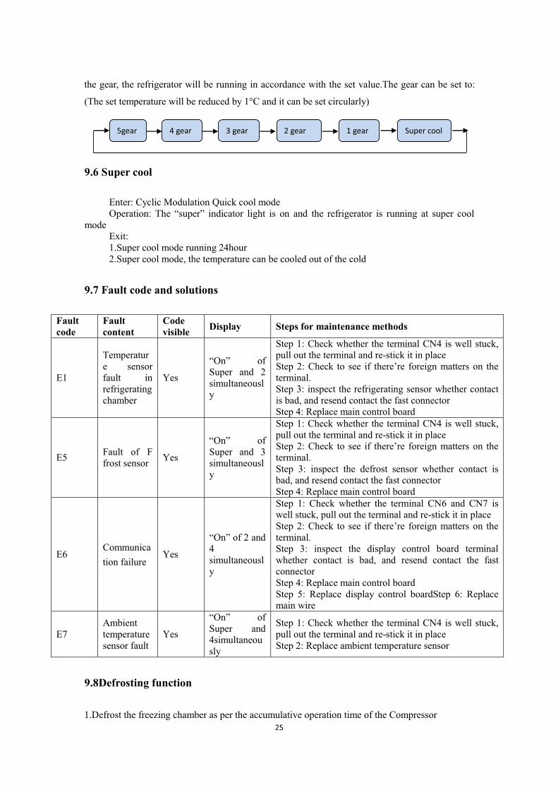
9.6 SUPER COOL .................................................................................................................................. 25
9.7 FAULT CODE AND SOLUTIONS ........................................................................................................ 25
9.8DEFROSTING FUNCTION ................................................................................................................. 25
9.9TEST MODE..................................................................................................................................... 26
9.10SELF-DIAGNOSIS .......................................................................................................................... 27
10.CIRCUIT DESCRIPTION10.1 POWER SUPPLY .................................................................................... 27
10.2DOOR TRIP TEST CIRCUIT .............................................................................................................. 28
10.3TEMPERATURE TEST CIRCUIT ........................................................................................................ 28
10.4FAN MOTOR CIRCUIT OF THE FREEZING CHAMBER ........................................................................ 29
10.5REFRIGERATOR FAN MOTOR CIRCUIT (NONE) ............................................................................... 29
10.6CONDENSING FAN MOTOR CIRCUIT (NONE) .................................................................................. 29
10.7DAMPER MOTOR CIRCUIT (NONE) ................................................................................................ 29
10.8RESISTANCE VALUE OF THE SENSOR (R/T) .................................................................................... 29
11.TROUBLESHOOTING METHOD........................................................................................... 31
11.1 NO REFRIGERATION ..................................................................................................................... 31
11.2 COMPRESSOR FAILURE................................................................................................................. 32
11.3 UNDERCOOLING(ELECTRONIC TEMPERATURE-CONTROL)............................................................ 32
11.4 FAN FAILURE ................................................................................................................................ 33
11.5NOISE ........................................................................................................................................... 33
11.6 LIGHTS INSIDE THE REFRIGERATOR DON’T LIGHT UP .................................................................... 34
12. FIGURES AND DETAILS OF REPAIR PARTS(DOCUMENTS ARE PROVIDED
SEPARATELY) ............................................................................................................................... 35
12.1 FIGURE ........................................................................................................................................ 35
12.2 LIST OF PARTS AND COMPONENTS ................................................................................................ 35
13APPENDIX: ...................................................................................................................................... 35
13.1ELECTRICAL SCHEMATIC DIAGRAM ............................................................................................. 35
13.2REFRIGERATOR MAINTENANCE TOOLING AND EQUIPMENT AND MATERIAL .................................. 35

1
1.Safety Warning Code
1.1Warning for operation safety
2

3

4
1.2Safety instruction for refrigerant

5
2.Description for product features
This product is provided with following features:
(The picture is only for reference, and specific appearance and configuration are subject to the real
product)
1) Full air-cooling and frost-free design
2) Display control board is located on the door
3) Magnetically control switch
4) Electronic temperature control system with more accurate temperature control.

6
3.Installation and commissioning
3.1Handling
1) Protecttherefrigeratorinmovingit
Sameasshownasleftphoto,pleasemoveitbyhandcartwi
thcushion
2) Removeallpackingmaterialsandbottomcushion,then
moveintohouseforplacement
3) Aftermovingittoappropriatelocation,waitfor2hoursbe
forepoweron.
3.2Disassembly (None)
The refrigerator door needs to be dismantled if it cannot enter the room in the whole.
3.3 Installation location
Location that is easy for ventilation shall be
chosen to facilitate heat dissipation, enhance
its performance and reduce the energy
consumption.

7
3.4 Leveling of the refrigerator
If the refrigerator cannot be placed steadily,
adjust the footing to level it.
3.5Change the door opening direction
1、Remove the hinge cover and plates from the
top of refrigerator
2、Pull out the fast connector of door signal
wire, remove the upper hinge screw, then
remove the upper hinge
3、Pull out the door ,remove the bottom hinge

8
4、Reversal the bottom hinge, Unscrew the
hinge pin from the bottom hinge and move it to
the other side(a), then secure the bottom hinge to
the bottom left side of the refrigerator
5、Remove the door block from the bottom, right
side of the door and attach it to the other side.
6、Install the door and the signal to other side,
connect the terminal and install upper hinge(a),
lid the upper hinge cover and the door end cap
9
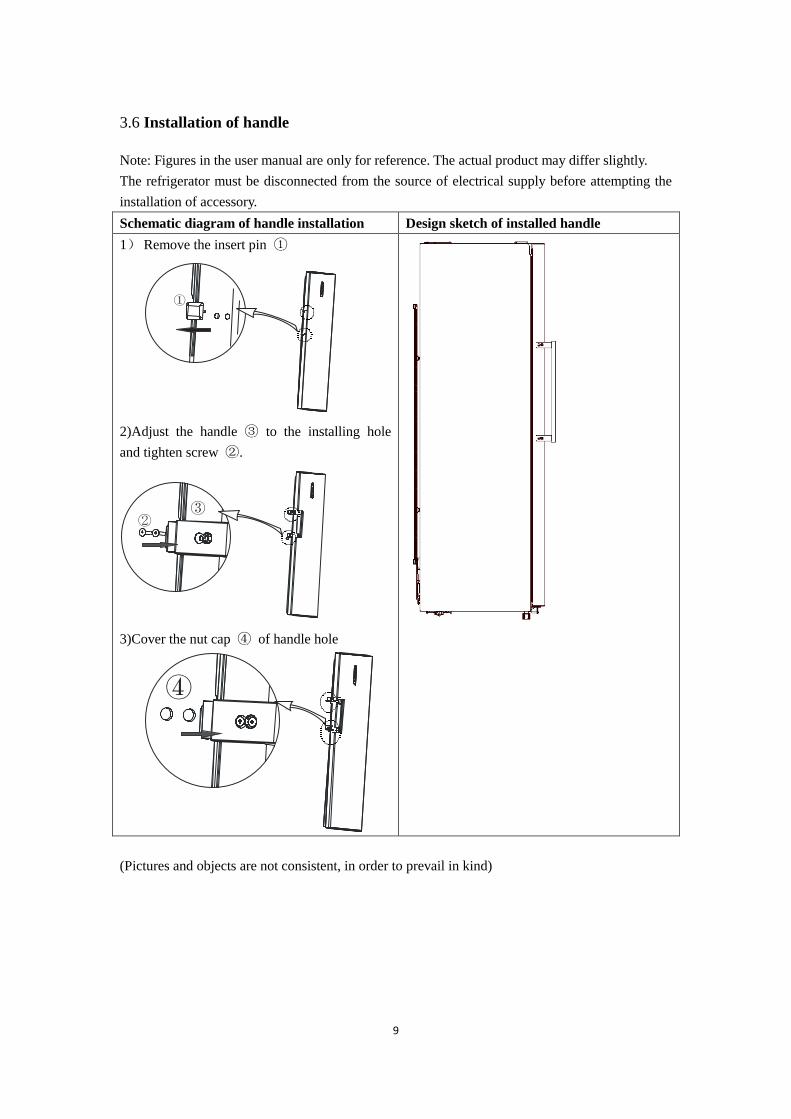
3.6 Installation of handle
Note: Figures in the user manual are only for reference. The actual product may differ slightly.
The refrigerator must be disconnected from the source of electrical supply before attempting the
installation of accessory.
Schematic diagram of handle installation Design sketch of installed handle
1) Remove the insert pin ①
①
2)Adjust the handle ③ to the installing hole
and tighten screw ②.
②③
3)Cover the nut cap ④ of handle hole
④
(Pictures and objects are not consistent, in order to prevail in kind)

10
3.7 Installation of door lock(None)
3.8 Adjustment to level the door(None)
3.9 Adjustment to shelves(None)
4.Terms
4.1 Definition of model(None)
4.2Location of nameplate
(The picture is only for reference, and specific appearance and configuration are subject to the real
product)
Lable

11
5.Product specification
5.1 typespecification(None)
5.2 Electrical parameters
Product Name CE-BC350WE-ST
Product Code 22031010001501
Name Item Type Specification
Compresso
r
Compressor / D53CY1
Starter PTC QP2-15
Overload protector OLP 3TM129NF1/TB35-120
Winding resistance of
compressor wiring terminal
44.8Ω±7%
26.7Ω±7%
Variable frequency driver
board / /
Motor
Fan motor of the refrigerating
chamber DC12V/≤3W
Ventilation door of the
refrigerating chamber / /
Condensation fan / /
Lights
inside the
refrigerato
r
Lights inside the freezing
chamber / /
Lights inside the refrigerating
chamber LED
DC12V
Switch of the refrigerator door / DC12V
5.3Refrigerating temperature
Temperature tolerance ≤ 2°C
Compartment The highest (oC) Lowest (
oC)
Freezing / /
Refrigerating 9 1
Variable temperature / /
5.4Defrosting parts
Defrosting period Initial defrosting period Normal defrosting period
Temperature is lower than 0 oC 6~24 hours
Defrosting sensor / /
Thermal fuse / /
12
Defrosting heater in freezing chamber / /
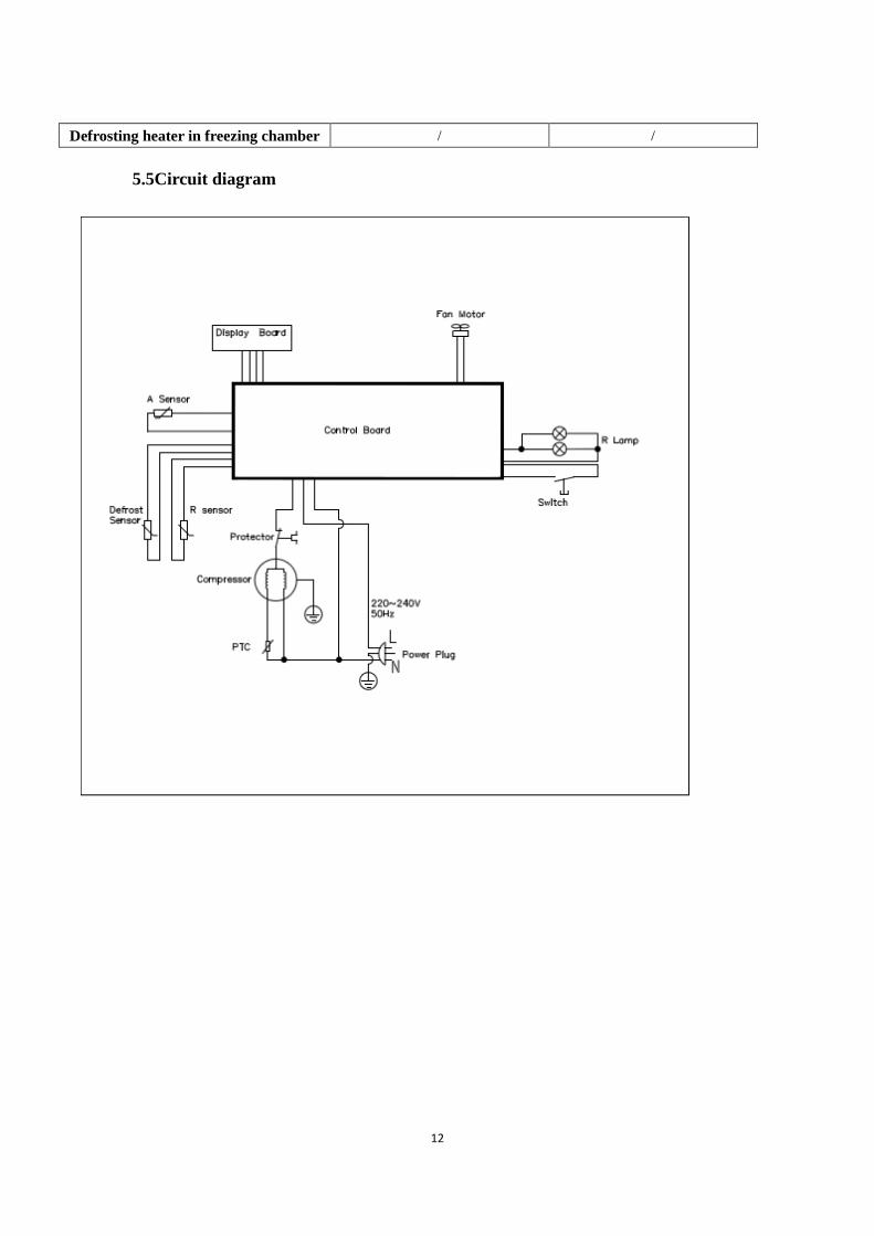
5.5Circuit diagram

13
6.Internal view and dimension
6.1Main parts and their names
(The picture is only for reference, and specific appearance and configuration are subject to the real
product)
1.Magnetically controlled switch
2.Air duct components in refrigerating
chamber
3.Glass shelve
4.Air duct components in refrigerating
chamber
5.Cover plate of crisper
6.Crisper for fruit and vegetable
7.Regulating foot
8.Big bottle frame in refrigerating chamber
9. Small bottle frame in freezing chamber
10. Water tank assembly
6.2External dimension
Front view Side view

14
Down view Open Door
Maximum open angle of door(135°)
(The picture is only for reference, and specific appearance and configuration are subject to the real
15
product)
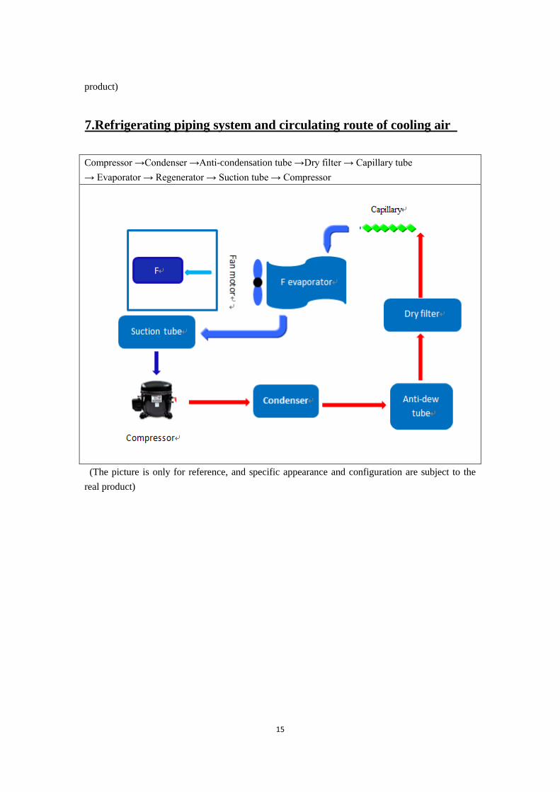
7.Refrigerating piping system and circulating route of cooling air
Compressor →Condenser →Anti-condensation tube →Dry filter → Capillary tube
→ Evaporator → Regenerator → Suction tube → Compressor
(The picture is only for reference, and specific appearance and configuration are subject to the
real product)

16
7.2Circulating route of cooling air
(The picture is only for reference, and specific appearance and configuration are subject to the real
product)
17
8. Dismantling of parts
8.1 Parts on the door
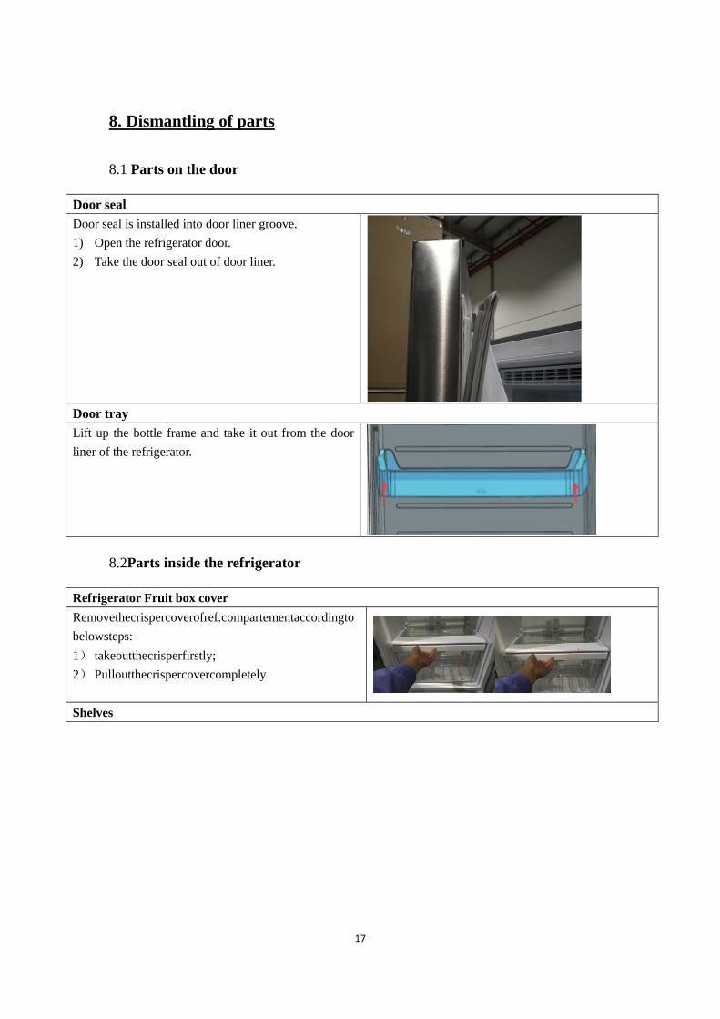
Door seal
Door seal is installed into door liner groove.
1) Open the refrigerator door.
2) Take the door seal out of door liner.
Door tray
Lift up the bottle frame and take it out from the door
liner of the refrigerator.
8.2Parts inside the refrigerator
Refrigerator Fruit box cover
Removethecrispercoverofref.compartementaccordingto
belowsteps:
1) takeoutthecrisperfirstly;
2) Pulloutthecrispercovercompletely
Shelves
18
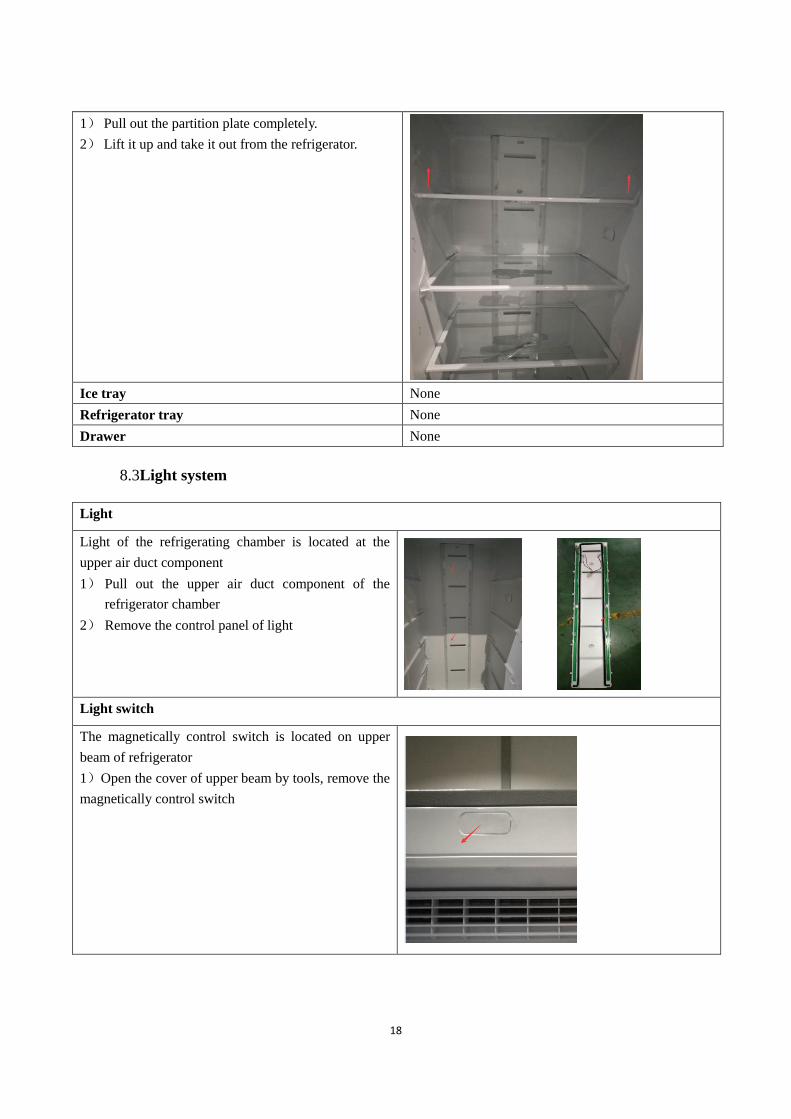
1) Pull out the partition plate completely.
2) Lift it up and take it out from the refrigerator.
Ice tray None
Refrigerator tray None
Drawer None
8.3Light system
Light
Light of the refrigerating chamber is located at the
upper air duct component
1) Pull out the upper air duct component of the
refrigerator chamber
2) Remove the control panel of light
Light switch
The magnetically control switch is located on upper
beam of refrigerator
1)Open the cover of upper beam by tools, remove the
magnetically control switch

19
8.4Air duct and fan motor
Air duct components in freezer chamber
All accessories in the freezer chamber should be
dismantled before removing the air duct components.
1) Remove 2 screws on the cover plate of the
refrigerator air duct using a cross screwdriver;
2) Pull out the connector terminal of the fan motor;
3) pull out the cap of the refrigerator upper air duct,
and then remove the 2 screw of the refrigerator
upper air duct components
4) Pull out the connector
Fan motor
1) Tear off the kraft paper tape
2) Remove the fan motor from the air duct component
3) Replace
the fan motor, the reverse operation for assembly
Damper assembly None
8.5Evaporator and temperature sensing system
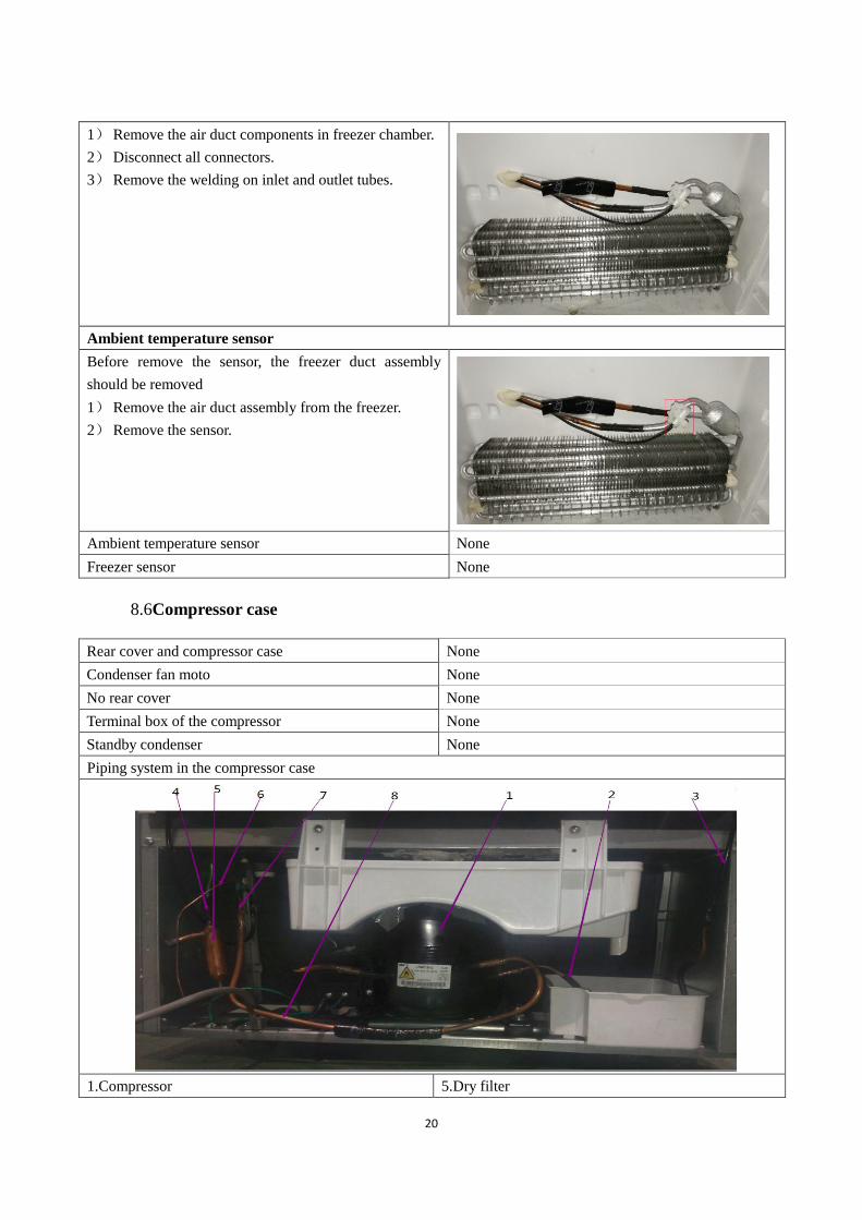
Evaporator in freezing chamber
20
1) Remove the air duct components in freezer chamber.
2) Disconnect all connectors.
3) Remove the welding on inlet and outlet tubes.
Ambient temperature sensor
Before remove the sensor, the freezer duct assembly
should be removed
1) Remove the air duct assembly from the freezer.
2) Remove the sensor.
Ambient temperature sensor None
Freezer sensor None
8.6Compressor case
Rear cover and compressor case None
Condenser fan moto None
No rear cover None
Terminal box of the compressor None
Standby condenser None
Piping system in the compressor case
1.Compressor 5.Dry filter

21
2.Exhaust transition pipe
3.Condenser
4.Anti-condensationg tube
6.Capillary
7.Suction pipe
8.Return transition pipe
Starter and protector of the compressor
1. Remove the screws
1) Two screws outside
2) One screw inside
2. Remove the clipping strip
Slowly pull it out
3. Remove the protective cover
1)Pry the protective cover slowly from the upper part,
2)Pull it out and remove it.
4. Remove the starter and protector
Unplug the starter and protector (you can use a
screwdriver to pry it slowly)
5. The reverse process can complete installation. /
8.7Display and main control panel
Display control board

22
1) Use vacuum cap to pull the control panel
outwards
2) Disconnect the connector of display control
board, remove it
Main control board
Main control board is located in the top of the
refrigerator
1) Remove the main control board screw with a
Phillips screwdriver
2) Disconnect the connector of main control
board, remove it
8.8 Bar counter(None)
Disassembly and installation of bar counter None
Disassembly and installation bar doorseal None
8.9 Water dispenser
Disassembly and installation of water tank

23
Disassembly and installation of water valve
Disassembly and installation of getting water cap
component
8.10 Ice maker(None)
Disassembly and installation of ice maker None
Disassembly and installation of water system None
Disassembly and installation ice machine sensor None
24
9. Function and operation
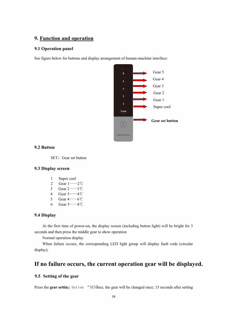
9.1 Operation panel
See figure below for buttons and display arrangement of human-machine interface:
Gear 5
Gear 4
Gear 3
Gear 2
Gear 1
Super cool
Gear set button
9.2 Button
SET:Gear set button
9.3 Display screen
1 Super cool 2 Gear 1——2℃
3 Gear 2——3℃ 4 Gear 3——4℃ 5 Gear 4——6℃
6 Gear 5——8℃
9.4 Display
At the first time of power-on, the display screen (including button light) will be bright for 3 seconds and then press the middle gear to show operation
Normal operation display When failure occurs, the corresponding LED light group will display fault code (circular
display);
If no failure occurs, the current operation gear will be displayed.
9.5 Setting of the gear
Press the gear setting button “SET” once, the gear will be changed once; 15 seconds after setting
the gear, the refrigerator will be running in accordance with the set value.The gear can be set to:
(The set temperature will be reduced by 1°C and it can be set circularly)
4 gear 5gear 3 gear 2 gear 1 gear Super cool

26
2.If power failure occurs abruptly to the Compressor and the defrosting sensor in freezing chamber
is less than 0 o
C after powering on, then first conduct defrosting once. If more than 0 o
C, then
defrosting is not needed.
After that, conduct defrosting according to using condition and ambient temperature in a period
between 6 and 24 hours as per the accumulative operation time of the Compressor.
9.9Test mode
Test
module
Test
items Testing Method Expected result
Test
Mode
Enter Test
Mode
Keep pressing the SET button
for 5 seconds and release
LED indicators on quick cool and Gear 1, 2, 3, 4
light up and flicker in the frequency of 0.5s, then
the refrigerator enters into test mode
After entering into test mode,
if no button is pressed within
15 seconds
then the refrigerator will exit the test mode and
return to normal operation mode
Select to
enter into
forced
cooling
mode
Enter into test mode and press
button for the first time
LED indicators on Gear 1, 2 and quick cool light
up and other LED indicators light off, then the
compressor and the fan will start working
In forced cooling mode, if no
button is pressed within 36
hours,
then the refrigerator will exit the test mode and
return to normal operation mode
Select to
enter into
forced
defrosting
mode
Enter into test mode and press
button for the second time
LED indicators on Gear 2, 3 and 4 light up and
other LED indicators light on, then the
compressor and the fan will stop working, The
heater open, refrigerator into forced frost
In forced defrosting mode,
when the defrosting sensor
reach a temperature of 8°C and
the defrosting heater has been
working for 3 minutes,
then the refrigerator will exit the test mode and
return to normal operation mode
In forced defrosting mode, if
the temperature of defrosting
sensor is always lower than
8°C and the compressor has
been stop working more than 5
hour.
then the refrigerator will exit the test mode and
return to normal operation mode
Select to
exit the
test mode
Enter into test mode and press
button for the third time
then the refrigerator will exit the test mode and
return to normal operation mode

27
9.10Self-diagnosis
Conditions for entering into this mode
When the power is on for the first time, here is no sensor failure and the defrost sensor
temperature is equal to or more than 0°C.
Self-diagnosis process
1. Defrost heater is on for 2 seconds and off for 2 seconds;
2.The fan is on for 10 seconds and off for 2 seconds;
3.The refrigerator is refrigerating for 20 minutes. (The compressor fans are all on)
Exit out of self-diagnosis
1、
1.Stop self-diagnosing and turn into normal mode;
2.Failure occurs to the sensor during self-diagnosis and exit out of self-diagnosis mode;
3.Set forced defrosting function during self-diagnosis.
10.Circuit description10.1 Power Supply
The AC input power is reduced in voltage by SMPS control chip and filtered off wave by the
inductance-capacitance filter, then output the DC 12V power which will mainly power the relay
that controls strong current. Relay is used to control the strong current loaded switches of
compressor, ice maker and defrost heater. The DC 12V power will output stable 5V electricity
after passing through the adjustor 7805, to power for the main control chip and thus monitor the
temperature changes in refrigerator.

28
10.2Door trip test circuit
The door switch input circuit is used to detect the refrigerator door open or not the circuit module.
Chip I/O PORT port. by testing the continuous high level + 5V to determine whether the door is
open. And then drive the relevant load
10.3Temperature test circuit
It’s conducted by the sensor, making use of the characteristics that resistance value reduces as the
temperature increases, and the thermistor that has temperature coefficient of resistance in medium
temperature.
The characteristic that resistance value reduces as the temperature increases is deemed to have
negative slope or negative temperature coefficient (NTC), and such thermistor is called as NTC
thermistor. The resistance value changes sensitively with temperature and typically changes 7% ~
29
3% per degree centigrade. Sensor used in the refrigerator is NTC thermistor.
There is following computing formula for the sensor:
Sampling voltage / reference voltage = R1 / (RNTC + R1)
AD value / reference AD value = R1 / (RNTC + R1)
The reference voltage is 5V, RNTC is the resistance value of the sensor, R1 is R31\R32\R33 in
schematic diagram that is 5.1K
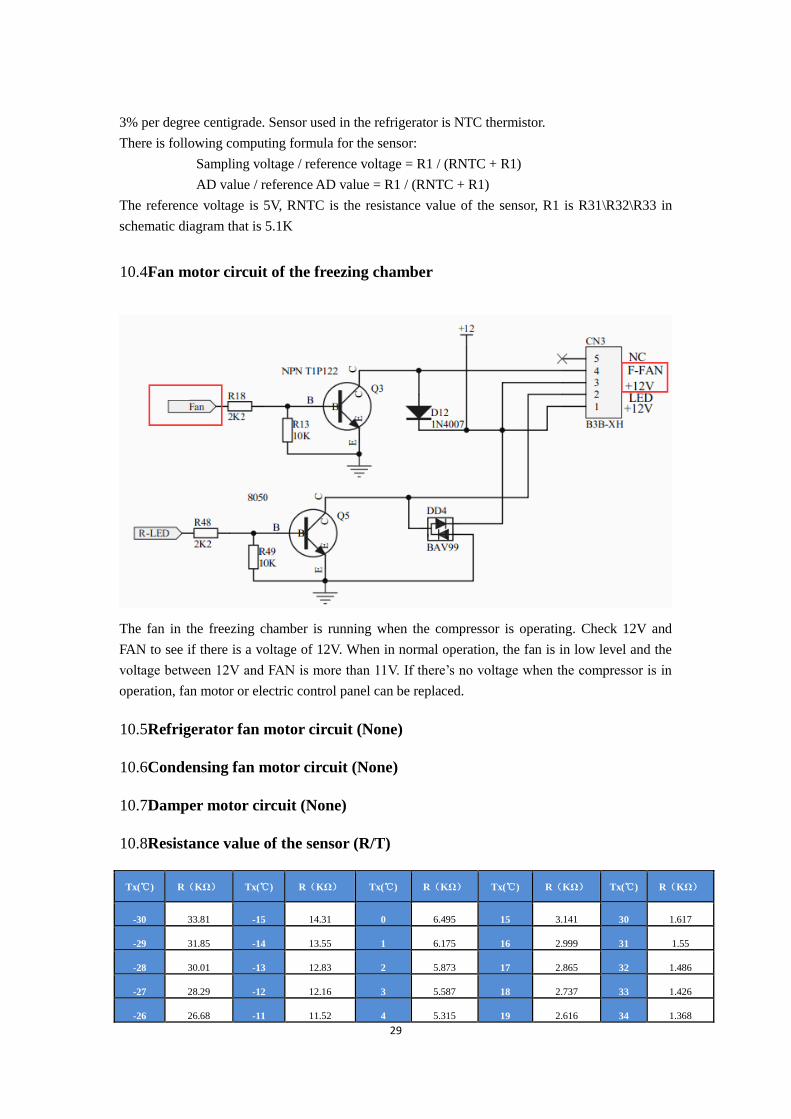
10.4Fan motor circuit of the freezing chamber
The fan in the freezing chamber is running when the compressor is operating. Check 12V and
FAN to see if there is a voltage of 12V. When in normal operation, the fan is in low level and the
voltage between 12V and FAN is more than 11V. If there’s no voltage when the compressor is in
operation, fan motor or electric control panel can be replaced.
10.5Refrigerator fan motor circuit (None)
10.6Condensing fan motor circuit (None)
10.7Damper motor circuit (None)
10.8Resistance value of the sensor (R/T)
Tx(℃) R(KΩ) Tx(℃) R(KΩ) Tx(℃) R(KΩ) Tx(℃) R(KΩ) Tx(℃) R(KΩ)
-30 33.81 -15 14.31 0 6.495 15 3.141 30 1.617
-29 31.85 -14 13.55 1 6.175 16 2.999 31 1.55
-28 30.01 -13 12.83 2 5.873 17 2.865 32 1.486
-27 28.29 -12 12.16 3 5.587 18 2.737 33 1.426
-26 26.68 -11 11.52 4 5.315 19 2.616 34 1.368

30
-25 25.17 -10 10.92 5 5.06 20 2.501 35 1.312
-24 23.76 -9 10.35 6 4.818 21 2.391 36 1.259
-23 22.43 -8 9.82 7 4.589 22 2.287 37 1.209
-22 21.18 -7 9.316 8 4.372 23 2.188 38 1.161
-21 20.01 -6 8.841 9 4.167 24 2.094 39 1.115
-20 18.9 -5 8.392 10 3.972 25 2.005 40 1.071
-19 17.87 -4 7.968 11 3.788 26 1.919 41 1.029
-18 16.9 -3 7.568 12 3.613 27 1.838 42 0.9885
-17 15.98 -2 7.19 13 3.447 28 1.761 43 0.9506
-16 15.12 -1 6.833 14 3.29 29 1.687 44 0.914
31
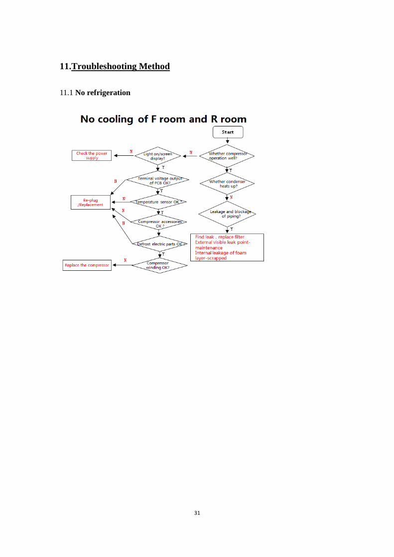
11.Troubleshooting Method
11.1 No refrigeration
32
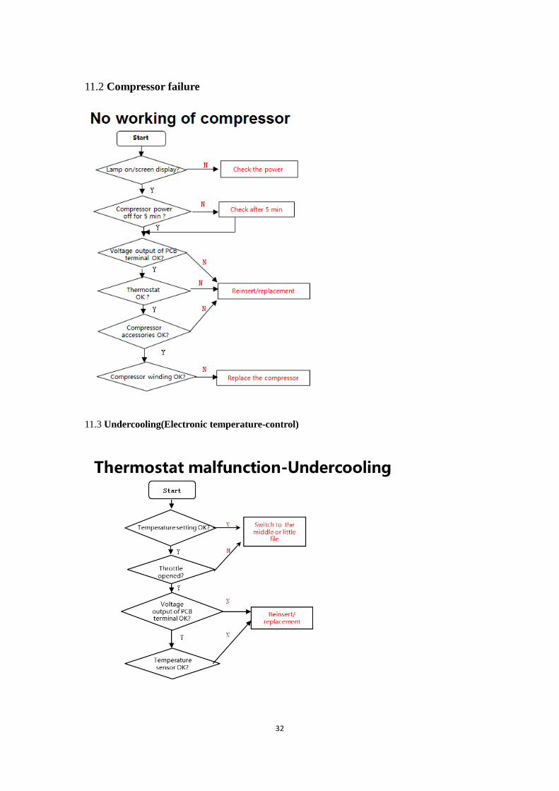
11.2 Compressor failure
11.3 Undercooling(Electronic temperature-control)

33
11.4 Fan failure
11.5Noise

34
11.6 Lights inside the refrigerator don’t light up

35
12. Figures and details of repair parts(Documents are provided
separately)
12.1 Figure
12.2 List of parts and components
13Appendix:
13.1Electrical Schematic Diagram
13.2refrigerator maintenance tooling and equipment and material
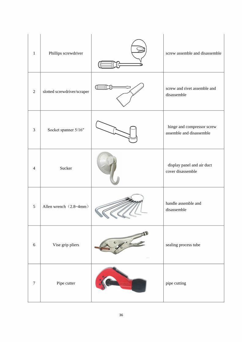
Tooling
No. Name Photo Main Usage
36
1 Phillips screwdriver
screw assemble and disassemble
2 slotted screwdriver/scraper
screw and rivet assemble and
disassemble
3 Socket spanner 5/16″
hinge and compressor screw
assemble and disassemble
4 Sucker
display panel and air duct
cover disassemble
5 Allen wrench(2.8~4mm)
handle assemble and
disassemble
6 Vise grip pliers
sealing process tube
7 Pipe cutter
pipe cutting
37
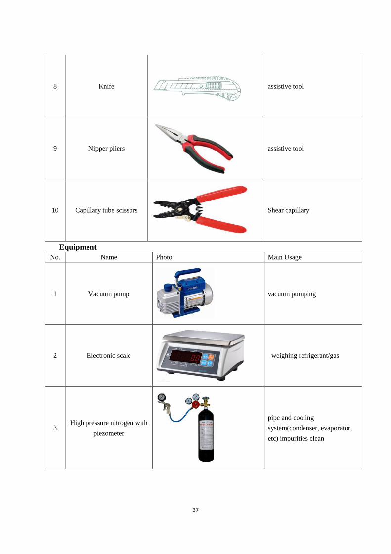
8 Knife
assistive tool
9 Nipper pliers
assistive tool
10 Capillary tube scissors
Shear capillary
Equipment
No. Name Photo Main Usage
1 Vacuum pump
vacuum pumping
2 Electronic scale
weighing refrigerant/gas
3 High pressure nitrogen with
piezometer
pipe and cooling
system(condenser, evaporator,
etc) impurities clean

38
4 Soldering gun
heating and welding
5 Quick coupling
connection process
pipeline,vacuumorchargerefriger
antwillbeused.
6 hand leak detector
welding point leakage detect, if
no, use soap-suds
material
No. Name Photo Main Usage
1 Process pipeline
Chargetherefrigerant
2 Dry filter
Involving a system failure to be
replaced
3 Copper welding rod
tube welding
4 Refrigerant/gas
Add refrigerant to the system
39
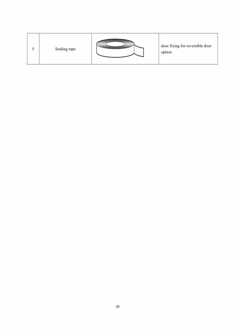
5 Sealing tape
door fixing for reversible door option
