dmp xr2500f addressable fire alarm control panel - digital
TRANSCRIPT

InstallatIon GuIde
XR2500F addRessaBle FIRe alaRM ContRol Panel

MODEL XR2500FCOMMAND PROCESSORINSTALLATION GUIDE
FCC NOTICE
This equipment generates and uses radio frequency energy and, if not installed and used properly in strict accordance with the manufacturer’s instructions, may cause interference with radio and television reception. It has been type tested and found to comply with the limits for a Class A computing device in accordance with the specification in Subpart J of Part 15 of FCC Rules, which are designed to provide reasonable protection against such interference in a residential installation. If this equipment does cause interference to radio or television reception, which can be determined by turning the equipment off and on, the installer is encouraged to try to correct the interference by one or more of the following measures:
Reorient the receiving antennaRelocate the computer with respect to the receiverMove the computer away from the receiverPlug the compute into a different outlet so that computer and receiver are on different branch circuits
If necessary, the installer should consult the dealer or an experienced radio/television technician for additional suggestions. The installer may find the following booklet, prepared by the Federal Communications Commission, helpful:
“How to identify and Resolve Radio-TV Interference Problems.”
This booklet is available from the U.S. Government Printing Office, Washington D.C. 20402
Stock No. 004-000-00345-4
© 2008 Digital Monitoring Products, Inc.
Information furnished by DMP is believed to be accurate and reliable.This information is subject to change without notice.

XR2500F Installation Guide Digital Monitoring Productsi
taBle oF Contents
Introduction1.1 Overview ...................................................................................................... 11.2 System Components ...................................................................................... 11.3 Power Specifications ...................................................................................... 11.4 Communication ............................................................................................. 11.5 Panel Zones .................................................................................................. 11.6 Keypad Bus ................................................................................................... 11.7 LX-Bus™ ....................................................................................................... 21.8 Outputs ........................................................................................................ 21.9 Relays .......................................................................................................... 21.10 Zone Reference ............................................................................................. 21.11 Compliance Instructions ................................................................................. 2
Mounting2.1 Mounting the Enclosure .................................................................................. 32.2 Surface Mounting .......................................................................................... 32.3 Flush Mounting .............................................................................................. 32.4 Fire Command Center LCD Keyboard ............................................................... 32.5 Metal Backplate ............................................................................................. 32.6 Wiring Diagram ............................................................................................. 4
AC Connection3.1 Transformers and AC Power Connection .......................................................... 53.2 16 VAC Transformer ...................................................................................... 53.3 Earth Ground (GND) ..................................................................................... 5
Secondary Power Supply4.1 Description .................................................................................................... 64.2 Battery Connection to XR2500F Command Processor panel ............................... 6
Two 866 NAC Modules5.1 Description .................................................................................................... 75.2 Connection .................................................................................................... 75.3 Bell Silence/Bell Trouble ................................................................................. 7
LX-Bus™ Operation6.1 Description .................................................................................................... 86.2 XR2500F On-board LX-Bus ............................................................................ 86.3 LX-Bus 481 Zone Expansion Interface Card ...................................................... 86.4 Installing the 481 Card ................................................................................... 8
893A Dual Phone Line Module7.1 Description .................................................................................................... 97.2 Connection .................................................................................................... 97.3 Jumper Settings ............................................................................................ 97.4 Digital Dialer ................................................................................................. 97.5 Phone Line Monitor ........................................................................................ 97.6 Processor Fail Buzzer ..................................................................................... 97.7 J10 893A Connector ....................................................................................... 97.8 Ground start .................................................................................................. 97.9 Notification ..................................................................................................107.10 FCC Registration ..........................................................................................10
Fire Command Center8.1 Description ...................................................................................................118.2 Connection ...................................................................................................118.3 Remote Fire Command Center .......................................................................11
Expansion9.1 Zone Expansion ............................................................................................129.2 Output Expansion .........................................................................................12

Digital Monitoring Products XR2500F Installation Guideii
taBle oF Contents
Accessory Devices10.1 Wiring Diagram ............................................................................................1310.2 Lightning Protection ......................................................................................1310.3 Accessory Devices ........................................................................................1410.4 Mounting Keypads and Zone Expansion Modules .............................................1510.5 Connecting LX-Bus and Keypad Bus Devices ...................................................15
Battery Information11.1 Battery Only Restart .....................................................................................1611.2 Battery Replacement Period...........................................................................1611.3 Discharge/Recharge ......................................................................................1611.4 Battery Supervision .......................................................................................1611.5 Battery Cutoff ...............................................................................................1612.6 XR2500F Power Requirements .......................................................................1611.7 XR2500F Standby Battery Calculations ...........................................................1711.8 Standby Battery Selection .............................................................................19
Bell Output12.1 Terminals 5 and 6 .........................................................................................20
Keypad Bus13.1 Description ...................................................................................................2013.2 Terminal 7 - RED ..........................................................................................2013.3 Terminal 8 - YELLOW ....................................................................................2013.4 Terminal 9 - GREEN ......................................................................................2013.5 Terminal 10 - BLACK .....................................................................................2013.6 J8 Programming Connection ..........................................................................2013.7 OVC LED ......................................................................................................20
Smoke and Glassbreak Detector Output14.1 Terminals 11 and 12 .....................................................................................2114.2 Current Rating ..............................................................................................21
Powered Zones for 2-Wire Smoke Detectors15.1 Terminals 25–26 and 27–28 ..........................................................................2115.2 Compatible 2-Wire Smoke Detector Chart .......................................................22
Protection Zones16.1 Terminals 13–24 ...........................................................................................2316.2 Operational Parameters .................................................................................2316.3 Zone Response Time .....................................................................................2316.4 Keyswitch Arming Zone .................................................................................23
Dry Contact Relay Outputs17.1 Description ...................................................................................................2417.2 Contact Rating .............................................................................................2417.3 Output Harness Wiring ..................................................................................24
J11 Annunciator Outputs18.1 Description ...................................................................................................2518.2 Model 300 Harness Wiring .............................................................................2518.3 Model 860 Relay Module ...............................................................................25
J23 6-Pin Header19.1 Description ...................................................................................................25
J22 LX-Bus Expansion Connector20.1 Description ...................................................................................................2620.2 LX-Bus Interface Cards ..................................................................................2620.3 LX-Bus LEDs .................................................................................................2620.4. OVC LED ........................................................................................................26
J21 Serial Connector21.1 Description ...................................................................................................2621.2 Serial Connector LEDs ...................................................................................26

XR2500F Installation Guide Digital Monitoring Productsiii
taBle oF Contents
J1 Ethernet Connector22.1 Description ......................................................................................................2722.2 Ethernet LEDs ..............................................................................................27
Reset and Tamper Headers23.1 J16 Reset Header ........................................................................................2723.2 J4 Tamper Header .......................................................................................27
Listed Compliance Specifications24.1 Introduction .................................................................................................28
Universal UL Burglary Specifications25.1 Introduction .................................................................................................2825.2 Wiring..........................................................................................................2825.3 Control Outside of Protected Area ..................................................................2825.4 Police Station Phone Numbers .......................................................................2825.5 Bypass Reports .............................................................................................2825.6 System Maintenance .....................................................................................2825.7 Listed Receivers............................................................................................2825.8 Power Supply Supervision .............................................................................2825.9 Wireless Tamper ...........................................................................................2825.10 Wireless External Contact ..............................................................................2825.11 Wireless Supervision Time .............................................................................2825.12 Detect Wireless Jamming ..............................................................................28
Area Information26.1 Ownership ...................................................................................................2926.2 Annunciation ................................................................................................2926.3 Trouble Display .............................................................................................2926.4 Closing Wait .................................................................................................2926.5 Local Bell Supervision ...................................................................................29
Household Burglar-Alarm System Units ANSI/UL 102327.1 Audible Devices ............................................................................................2927.2 Auxiliary Circuits ...........................................................................................2927.3 Bell Cutoff ....................................................................................................2927.4 Entry Delay ..................................................................................................2927.5 Exit Delay ....................................................................................................2927.6 Weekly Test ..................................................................................................2927.7 Wireless Audible Annunciation Option ............................................................29
Central-Station and Proprietary Burglar-Alarm Units ANSI/ UL 1610 AND ANSI/UL 107628.1 Opening/Closing Reports ...............................................................................2928.2 Closing Wait .................................................................................................2928.3 Entry Delay ..................................................................................................2928.4 Exit Delay ....................................................................................................2928.5 Proprietary Dialer .........................................................................................3028.6 DACT Central Station ....................................................................................3028.7 Bell Cutoff ....................................................................................................3028.8 Standard or Encrypted Line Security...............................................................3028.9 Wireless Audible Annunciation Option ............................................................3028.10 Model 463G CELL Only, Standard or Encrypted Line Security ...........................3028.11 Model 463G NET with CELL as Alternate Primary and Dialer Backup,
Standard or Encrypted Line Security .............................................................3128.12 Model 463G NET with CELL as Backup and Adaptive Primary, Standard
or Encrypted Line Security ............................................................................31

Digital Monitoring Products XR2500F Installation Guideiv
taBle oF Contents
Holdup Alarm Units ANSI/UL 63629.1 ANSI/UL 1610 Required ................................................................................3229.2 1100X Wireless Receiver ...............................................................................3229.3 Wireless Supervision Time .............................................................................3229.4 LED Display ..................................................................................................3229.5 Jamming Detection .......................................................................................3229.6 Local Alarm ..................................................................................................3229.7 Message to Transmit .....................................................................................3229.8 Wireless Audible Annunciation Option ............................................................32
Digital Burglar Alarm Communicator System Units ANSI/ UL 163530.1 System Trouble Display .................................................................................3230.2 Digital Dialer Telephone Number ....................................................................3230.3 Test Time .....................................................................................................3230.4 Closing Wait .................................................................................................32
Police Station Connected and Local Burglar Alarm Units ANSI/UL 36531.1 System Trouble Display .................................................................................3231.2 Entry Delay ..................................................................................................3231.3 Exit Delay ....................................................................................................3231.4 Bell ..............................................................................................................3331.5 Bell Cutoff ....................................................................................................3331.6 Automatic Bell Test .......................................................................................3331.7 Standard or Encrypted Line Security...............................................................3331.8 Wireless Audible Annunciation Option ............................................................3331.9 Model 463G CELL Only, Standard or Encrypted Line Security ...........................3331.10 Model 463G NET with CELL as Alternate Primary and Dialer Backup,
Standard or Encrypted Line Security .............................................................3431.11 Model 463G NET with CELL as Backup and Adaptive Primary, Standard
or Encrypted Line Security ............................................................................34Police Station Connected and Local Burglar Alarm Units
ANSI/UL 60932.1 Mercantile ....................................................................................................3532.2 Entry Delay ..................................................................................................3532.3 Exit Delay ....................................................................................................3532.4 Bell ..............................................................................................................3532.5 Wireless Audible Annunciation Option ............................................................35
Access Control System Units ANSI/UL 29433.1 Panel Designation .........................................................................................3533.2 Compatible Devices ......................................................................................35
Universal Fire Alarm Specifications34.1 Introduction .................................................................................................3634.2 Wiring..........................................................................................................3634.3 Transformer .................................................................................................3634.4 End-of-Line Resistor ......................................................................................3634.5 System Trouble Display .................................................................................3634.6 Fire Display ..................................................................................................3634.7 Police Station Phone Number .........................................................................3634.8 System Maintenance .....................................................................................3634.9 Audible Alarm ...............................................................................................3634.10 Fire Zone Programming .................................................................................3634.11 Style D Zones ...............................................................................................3634.12 Listed Receivers............................................................................................36

XR2500F Installation Guide Digital Monitoring Productsv
taBle oF Contents
Control Units for Fire-Protective Signaling Systems ANSI/UL 864, NFPA 72 35.1 Power Supply ...............................................................................................3735.2 Zone Restoral Reports ...................................................................................3735.3 Power Fail Delay ...........................................................................................3735.4 Sprinkler Supervisory ....................................................................................3735.5 DACT Systems ..............................................................................................3735.7 Local Protective Signaling Systems .................................................................3735.8 Remote Station Protective Signaling Systems ..................................................3735.9 Fire Protective Signaling Systems using Internet/Intranet Networks ..................3735.10 Combination Systems ....................................................................................3735.11 Remote Annunciators ....................................................................................3735.12 Notification Appliances .................................................................................3835.13 Cross Zoning ..................................................................................................3835.14 Ground Fault ...............................................................................................38
Household Fire Warning System Units ANSI/UL 985, NFPA 7236.1 Bell Output Definition ....................................................................................3836.2 Audible Devices ............................................................................................3836.3 Auxiliary Circuits ...........................................................................................3836.4 Bell Cutoff ....................................................................................................38
California State Fire Marshal Specifications37.1 Bell Output Definition ....................................................................................39
New York City (MEA) Specifications38.1 Introduction .................................................................................................3938.2 Digital Dialer and Network Communication .....................................................3938.3 Wiring..........................................................................................................3938.4 Communication Programming ........................................................................3938.5 Additional Requirements ...............................................................................39
Wiring Diagrams39.1 Prewired 866 Modules with NAC Extender ......................................................4039.2 Prewired 866 Class B Style W Modules using Single Notification Appliance ........4039.3 Prewired 866 Class B Style W Modules with Multiple Notification Appliances ......4139.4 Prewired 866 Class B Style W Modules with Dual Notification Appliance Circuits 4239.5 867 Class B Style W using Single Notification Appliance ...................................4339.6 867 Class B Style W Multiple Notification Appliance Circuit ...............................4339.7 867 Class B Style W Multiple Notification Appliance Circuits .............................4439.8 Dual Style D Zone Module Installation ............................................................4539.9 Remote Station Reversing Relay Connection ...................................................4639.10 Second LX-Bus™ with Auxiliary Power Supply .................................................4739.11 LX-Bus™ Module Connection .........................................................................4839.12 Model 860 Relay Module Connection ..............................................................4939.13 Powered Burglary Devices ...............................................................................49
Revisions to This DocumentOPERATING INSTRUCTIONS MODEL XR2500F PANELS
Mounting Instructions ..............................................................................................52
Listings and Approvals

Digital Monitoring Products XR2500F Installation Guidevi
This page intentionally left blank

XR2500F Installation Guide Digital Monitoring Products1
IntRoduCtIon
Introduction
1.1 OverviewThe DMP XR2500F Addressable Fire Alarm Control Panel (FACP) is an expandable 24 VDC Fire Alarm Control with built-in DACT and LCD Fire Command Center keyboard with membrane keyswitch. A complete system can provide:
• 574programmableinputsandoutputsforcommercialandindustrialfirealarmservice.• Eighton-boardgroundedzones• Twoon-board12VDCClassB,StyeApoweredzonesConnecta12or24VDCregulated,powerlimitedpowersupplylistedforFireProtectiveSignalingSystemstodistributenotificationappliancepowerbetweenthetwoclassBstyleWNACoutputs.AdditionalNACoutputs can be added with conventional supervision modules or addressable power supply/boosters. AddressablesmokedetectorsandinputmodulesroundouttheXR2500Ftodeliveratrulyflexibleandexpansivefiredetectionandnotificationsystem.TheFireAlarmControlPanelisshippedpre-wiredinaredmetalenclosurehousingthenecessarycomponentstomonitorandcontrolfirealarmnotificationappliances.
Theenclosuredimensionsareasfollows:32”Hx14.5”Wx4”D.Thelidaddsabout0.5”toeachside.
1.2 System ComponentsTheXR2500FFACPconsistsofthefollowingpre-wiredcomponents:
• OneModelXR2500FCommandProcessorpanel •OneModel893ADualPhoneLinemodule• TwoModel866ClassBStyleWNACmodules •OneModel630FPCBandmembraneswitch• One16VAC,56VAtransformer •TwoModel305Plug-inRelays• OneModel481ZoneExpansionInterfaceCard •OneMetalBackplate
1.3 Power SpecificationsTransformerInput: Primaryinput:120VAC,60Hz,Secondaryoutput:16VAC56VAStandbyBattery: 12VDC,1.0AmpsMax.chargingcurrentAuxiliary: 12 VDC output at 1.0 Amp Max*BellOutput: 12VDCat.7AmpMax*Note:ThecombinedAuxiliaryandBelloutputstotalcannotexceed1.9Ampswitha56VATransformer.All circuits are inherent Power Limited except the red battery wire and AC terminal.* For Commercial Fire installations, see the Compliance Instructions section.
1.4 CommunicationBuilt-indialerornetworkcommunicationtoDMPModelSCS-1RReceiversBuilt-inContactIDcommunicationtonon-DMPreceivers893ADualPhoneLineModulewithphonelinesupervisionCan operate as a local panel
1.5 Panel ZonesEight1kOhmEOLburglaryzones(zones1to8).Connectto869ClassAmoduleforburglaryapplications.Two3.3kOhmEOLpoweredzonewithreset(zones9and10).Note:UsethesuppliedDMPModel3111kOhmandDMPModel3013.3kOhmresistors.
1.6 Keypad BusYoucanconnectupto15ofthefollowingsupervisedkeypadsandexpansionmodulestothekeypadbus:• AlphanumericFireCommandCentersorkeypads• Four-and/orsingle-zoneexpansionmodules• Single-zonedetectors• Accesscontrolmodules

Digital Monitoring Products XR2500F Installation Guide2
IntRoduCtIon
1.7 LX-Bus™YoucanconnectthefollowingdevicestotheLX-Bus™providedbytheDMP481(supplied)orbythe462N,481,462P,463G,and472InterfaceCardsuptothemaximumnumberofLX-Bus™addresses.SeeAccessoryDevices.• Model521LXor521LXTSmokeDetectorswithCleanMe• Sixteen-,eight-,four-and/orsingle-zoneexpansionmodules• Single-zonedetectors• Relayoutputexpansionmodules• Graphicannunciatormodules
1.8 OutputsTheXR2500Fprovidestwopre-installedModel305SinglePole,DoubleThrow(SPDT)relayoutputs,eachrated1Ampat30VDC(powerlimitedsourcesonly).
TheXR2500Falsoprovidesfourprogrammableopencollectoroutputsratedfor30VDC@50mAeach.Theopencollectoroutputsprovidegroundconnectionforapositivevoltagesource.AModel300OutputHarnessisrequiredtousetheseoutputsandmaybeconnectedtoaModel860RelayOutputModule.
1.9 Relays TheXR2500FshipswithtwoModel305Relayspre-installedtoallowzonealarmcontrolforthe866NACModules.Whenafirealarmoccursthebelloutputisfactoryprogrammedtoturnonandprovidepowertothecontactsoftherelays.Specificzoneprogrammingdetermineswhetheroneorbothrelaysturnonsignalvoltagetothe866NACs.ThisallowscontroloftheNACsbyzone.
1.10 Zone ReferenceTheXR2500Fhasbeenpre-wiredinthefactory.Thefirst866NACmoduleconnectstoZone1.Thesecond866NACmoduleconnectstoZone2.
1.11 Compliance InstructionsForapplicationsthatmustconformtoalocalauthoritiesinstallationstandardoraNationalRecognizedTestingLaboratorycertificatedsystem,pleaseseetheWiringDiagramsforNotificationAppliancesandtheListedComplianceSpecificationssectionneartheendofthisguideforadditionalinstructions.

XR2500F Installation Guide Digital Monitoring Products3
IntRoduCtIon
Mounting
2.1 Mounting the EnclosureTheXR2500Fmustbemountedinasecure,drylocationtoprotecttheunitfromdamageduetotamperingandtheelements.Theenclosurecanbeeitherflushmountedorsurfacemountedandincludesahingeddoorwith lock. The hole in the enclosure door allows access to the Fire Command Center withoutopeningthedoor.Figure1illustratesthemountingholelocationsforthepanelenclosure.
Theenclosuredimensionsare32”tall,14.5”wide,by4”deep.Thelidaddsabout0.5”toeach side.
2.2 Surface MountingThe enclosure center hole should be attached toawallstud.Duetotheenclosureweight,especiallythebatteries,itisextremelyimportant to mount the enclosure on the stud. Attach the two holes beside the center holetosheetrocktosecureenclosure.Whenmountingtheenclosure,besuretoleaveroomforthepaneldoortoswingopen.Thedoor lock should be easily accessible.
2.3 Flush MountingTheenclosurecanalsobeflushmounted.Use1”screwstosecuretheenclosurebetweentwostudsusingthetwosetsofholesonthesidesoftheenclosure.Usethetopandbottomholestosecuretohorizontalstuds,ifnecessary.
2.4 Fire Command Center LCD KeyboardA Fire Command Center LCD Keyboard hasbeenfactoryinstalledontheXR2500Fenclosure. A keyswitch has also been installedandpre-wiredtotheleftofthekeyboard. The user can turn the keyswitch to enablethefourfunctionkeyswithoutopeningthe enclosure door.
2.5 Metal BackplateThe XR2500F components are pre-wired and installed on a metal backplate. The backplatecanbeeasilyremovedtokeepcomponentssafeduringpre-wireactivities.
Remove AC and battery power from the XR2500F panel before removing the backplate. Disconnect all battery,transformer,andtheFireCommandCenterLCDkeyboardwires.Fromthepanel,disconnecttheACwiresfromterminals1and2.Disconnectthebatterywireseitherfromthebatteriesorthepanelterminals3and4.Finally,disconnectthekeyboardwiresfrompanelterminals7,8,9,and10.
Removethescrewssecuringthebackplatetotheenclosure.Loosenthetwotopscrewsthatthebackplatehangson.Afterlooseningandremovingthescrews,liftthebackplateupslightlyandpullthebackplatetowardyou.Whenreinstallingthebackplate,besureallconnectionsaresecure.
Figure2illustratesthebackplateandthecomponents.Thebackplateisshowninlightgray.
3/4" X 1/2" Knockouts
Hole for Flush Mounting
Holes for Surface Mounting
Holes for 1" screws for Flush Mounting
Battery Shelf
Hole for Flush Mounting
Additional Holes for Surface Mounting
Figure 1: Mounting the XR2500F Enclosure

Digital Monitoring Products XR2500F Installation Guide4
IntRoduCtIon
2.6 Wiring DiagramTheXR2500Fsystembelowshowsthecomponentlayout.Thewiresshowninthisguidehavebeenfactoryinstalledandconnected.Thedashedlinesrepresentwiresrunningunderneathorbehindacomponent.Detailedwiringdiagramsforeachsuppliedcomponentappearinfollowingsectionsofthisguide.
AC
1 2 3 4 5 6 7 8 10 11 12 13 14 15 16 17 18 199 20 21 22 23 24 25 26 27 28
+B BELLGND SMK GNDRED YEL GRN BLK Z1 Z2 Z3 Z4 Z5 Z6 Z7 Z8 Z9+ Z9– Z10+Z10–AC –B GND GND GNDGND
Output 1 Output 2
J3Phone Line
J22
BatteryStart
Power LED
J8PROG
J4Tamper
J16Reset
Out
1O
ut2
Outputs 3-6
3 4 5
J1Ethernet
RLX
Link LEDPower LED
OVC
XR2500FCommand
Processor™Panel J6
Exp
ansi
on
Car
d Sl
ot
TYPES OF SERVICE
Suitable for Mercantile Local and Police Station Connect.
Suitable for Proprietary, PPU, other technologies, local.
Suitable for Signaling and Remote Station PPU DACT Service.
Suitable for manual fire alarm, automatic fire alarm, sprinkler supervisory, or water flow alarm.
Suitable for Standard or Encrypted Central Station with NET or CELL communication.
Suitable for Household Fire and Household Burglary.
Suitable for Coded and March Time signaling.
NFPA 72This equipment should be installed in accordance with the National Fire Alarm Code, ANSI/NFPA 72 (National Fire Protection Association, Batterymarch Park, Quincy, MA 02269). Printed information describing proper installation, operation, testing, maintenance, evacuation planning, and repair service is to be provided with this equipment.
Zones 9, 10, and all expanded zones are suitable for Class B (as applicable for the initiating and signaling line circuits per ANSI/UL 864 Table 48.2 or 48.3). Installation limits under local Authority Having Jurisdiction (AHJ).
Control Unit Delay
Smoke Model
DetectorDelay
Verification Zones
WARNINGTHIS UNIT MAY BE PROGRAMMED TO USE AN ALARM VERIFICATION FEATURE THAT RESULTS IN DELAY OF THE SYSTEM ALARM SIGNAL FROM THE INDICATED CIRCUITS. THE TOTAL DELAY (CONTROL UNIT PLUS SMOKE DETECTORS) SHALL NOT EXCEED 60 SECONDS. NO OTHER SMOKE DETECTOR SHALL BE CONNECTED TO THESE CIRCUITS UNLESS APPROVED BY THE LOCAL AUTHORITY HAVING JURISDICTION (AHJ).
See LT-0759, 893A Dual Phone Line Module section for complete 893A information.
Refer to LT-0759, Standby Battery Selection section for battery standby times and numbers of batteries to use.
See LT-0759, Two 866 NAC Modules section for complete 866 information.
866 Module
866 Module
+ - + -
12 VDC battery
Two 12 VDC batteries connected in parallel with a Model 318 Dual Battery Harness. See Secondary Power Supply section.
XR2500F Secondary Power Supply 1 Amp maximum charge current. Use only 12 VDC rechargeable batteries. Replace every 3 to 5 years.
12 VDC battery
Blac
kRed
To Fire Command Center on enclosure doorFrom XR2500F panel to 12 VDC.
56 VA Transformer
GRO
UN
DG
REE
N
GREEN/YELLOW W
HIT
E
BLAC
K
WH
ITE
BLAC
K
To TelcoS
To Notification Appliances
S
S
S
S
S
SS
S
Battery Compartment
10K EOL
10K EOL
16 VAC
Expansion Zones
Connected to Enclosure Door
Use MarkingCommercial and Residential Fire, Burglar, Holdup, and
Access Protected Premise Unit
Figure 2: XR2500F System

XR2500F Installation Guide Digital Monitoring Products5
IntRoduCtIon
AC Connection
3.1 Transformers and AC Power ConnectionThe AC connection should be completed by a licensed electrician.
Never share the Fire Alarm Control Panel circuit with any other equipment.
TheXR2500Fcomessuppliedwitha16VAC56VAtransformer.The16VACtransformerwhiteleadsandblackleadsmustbeconnectedtoanunswitched120VAC60Hzpowersourcewithatleast.87Aavailable.Observewirecolorsandconnectthetransformerwires:
TheBlacktransformerwirestotheBlack120VACwire
TheWhitetransformerwirestotheWhite120VACwire
TheGreen/Yellowgroundwiretotheelectricalground
S
56 VA
Transformer
To XR2500F Panel
Violet
Terminal 1
Gray
Terminal 2
16 VAC
56 VA
Transformer
L-Bracket
Bracket
Nut
Bracket
Nut
GRO
UN
DG
REEN
GREEN/
YELLOW WH
ITE
BLA
CK
WH
ITE
BLA
CK
S
S
Connected to Enclosure Door
Figure 3: Transformers and AC Power Connection
Always ground the panel before applying power to any devices! Use18AWGorlargerforallpowerconnections.TheXR2500Fmustbeproperlygroundedbeforeconnectinganydevicesorapplyingpowertothepanel.PropergroundingprotectsagainstElectrostaticDischarge(ESD)thatcandamagesystemcomponents.
3.2 16 VAC Transformer The16VAC56VAtransformersuppliespowertotheXR2500Fpanelandisfactorypre-wired.SeeFigure3:TransformersandACPowerConnection.AlsorefertoFigure11:XR2500FPanelWiringDiagram.
3.3 Earth Ground (GND) TheXR2500Fterminal4mustbeconnectedtoearthgroundusing14AWGorlargerwiretoprovidepropertransientsuppression.DMPrecommendsconnectingtoacoldwaterpipe,buildingground,orgroundrodonly.Donotconnecttoanelectricalgroundorconduit,sprinklerorgaspipes,ortoatelephonecompanyground.

Digital Monitoring Products XR2500F Installation Guide6
IntRoduCtIon
Secondary Power Supply
4.1 DescriptionTheXR2500Fsystemincludespre-wiredcablesforconnecting12VDCbatterytotheXR2500Fpanel.Observepolaritywhenconnectingallbatteries.
Use sealed lead-acid batteries only.UsetheDMPModel367,368,369,365,366,12VDCsealedlead-acidrechargeablebatteries.BatteriessuppliedbyDMPhavebeentestedtoensureproperchargingwithDMPproducts.
GelcellbatteriescannotbeusedwiththeXR2500Fpanel.
4.2 Battery Connection to XR2500F Command Processor panelFor12VDCbatteryoperationtotheXR2500F,connecttheblackbatteryleadtothebatterynegativeterminal. The black battery wire connects to XR2500F panel terminal 4.
Connect the red battery lead to the battery positive terminal. The red battery wire connects to XR2500F panelterminal3.SeeFigure11andFigure2.
AddasecondbatteryinparallelusingtheDMPModel318DualBatteryHarness.WhenwiringtwobatterieswiththeModel318DualBatteryHarness,plugtheDualBatteryHarnessredmaleendintothepanelredfemalebatterylead.PlugtheDualBatteryHarnessblackmaleendintothepanelblackfemalebatterylead.AttachbothDualWiringHarnessfemaleleadstothetwobatteriesasdescribedabove.SeeTable3:BatteryCalculations.
XR2500F Installation Guide Digital Monitoring Products7
IntRoduCtIon
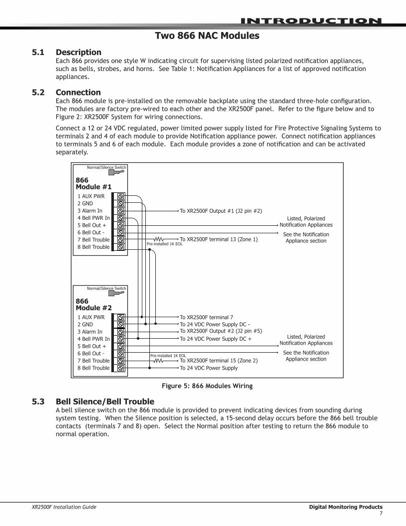
Two 866 NAC Modules
5.1 DescriptionEach866providesonestyleWindicatingcircuitforsupervisinglistedpolarizednotificationappliances,suchasbells,strobes,andhorns.SeeTable1:NotificationAppliancesforalistofapprovednotificationappliances.
5.2 ConnectionEach866moduleispre-installedontheremovablebackplateusingthestandardthree-holeconfiguration.Themodulesarefactorypre-wiredtoeachotherandtheXR2500Fpanel.RefertothefigurebelowandtoFigure2:XR2500FSystemforwiringconnections.
Connecta12or24VDCregulated,powerlimitedpowersupplylistedforFireProtectiveSignalingSystemstoterminals2and4ofeachmoduletoprovideNotificationappliancepower.Connectnotificationappliancestoterminals5and6ofeachmodule.Eachmoduleprovidesazoneofnotificationandcanbeactivatedseparately.
1 AUX PWR
2 GND
3 Alarm In
4 Bell PWR In
5 Bell Out +
6 Bell Out -
7 Bell Trouble
8 Bell Trouble
866
Module #1
Normal/Silence Switch
1 AUX PWR
2 GND
3 Alarm In
4 Bell PWR In
5 Bell Out +
6 Bell Out -
7 Bell Trouble
8 Bell Trouble
866
Module #2
Normal/Silence Switch
To XR2500F Output #1 (J2 pin #2)
To XR2500F terminal 13 (Zone 1)
To XR2500F terminal 7
To 24 VDC Power Supply DC -
To XR2500F Output #2 (J2 pin #5)
To 24 VDC Power Supply DC +
To XR2500F terminal 15 (Zone 2)
To 24 VDC Power Supply
Listed, Polarized Notification Appliances
See the Notification Appliance section
Listed, Polarized Notification Appliances
See the Notification Appliance section
Pre-installed 1K EOL
Pre-installed 1K EOL
Figure 5: 866 Modules Wiring
5.3 Bell Silence/Bell TroubleAbellsilenceswitchonthe866moduleisprovidedtopreventindicatingdevicesfromsoundingduringsystemtesting.WhentheSilencepositionisselected,a15-seconddelayoccursbeforethe866belltroublecontacts(terminals7and8)open.SelecttheNormalpositionaftertestingtoreturnthe866moduletonormal operation.

Digital Monitoring Products XR2500F Installation Guide8
IntRoduCtIon
LX-Bus™ Operation
6.1 DescriptionTheXR2500FCommandProcessor™panelsupportsLX-Busoperationdirectlyfromthepanel.EachLX-Buscircuitprovides100additionalzones.UseJ22LX-BusHeaderforthefirst100zones.Usetheinstalled481ZoneExpansionInterfaceCardforthenext100zones.Thisprovidesatotalof200expansionzones.ToinstalluptofouradditionalInterfaceCardsuseaModel461InterfaceAdaptorCard.
6.2 XR2500F On-board LX-Bus ToenableJ22tooperateasanLX-Bus,placeajumperonthetwopinsnexttotheletter“L”ontheJ236-Pinheader.WhenusingJ22asanLX-Bus,connectaDMPModel3004-wireHarnesstotheJ224-pinheaderlabeledLX-BUS.Thisprovidesthefirst100LX-Buszonesnumbered500-599.Respectwirecolorswhenconnectingdevicesanduseallfourwires.ResetthepanelusingtheJ16jumpertoactivateLX-Busoperation.SeeConnectingLX-BusandKeypadDevicessectionformaximumwiringdistances.
Note:DoNOTuseshieldedwirewhenusingtheLX-Bus.DoNOTconnectthewiresfromthe4-wireharnessto the panel terminals.
6.3 LX-Bus 481 Zone Expansion Interface CardThe481ZoneExpansionInterfaceCardprovidesanadditional100zonestotheXR2500F.Whenusedinconjunctionwiththeon-boardJ22LX-Busthe481LX-Buszonesarenumbered600to699.
6.4 Installing the 481 CardRemove AC and battery power from the XR2500F panel and ground yourself before handling and installing the 481 Card.
1.Alignthe481Card50pinconnectorwiththeXR2500FpanelJ6connector.2.Pressthe481ontotheJ6connectorwhileapplyingevenpressuretobothsides.
B
J6 Interface Card
Connector
18 19 20 21 22 23 24 25 26 27 28
Z5 Z6 Z7 Z8 Z9+ Z9- Z10+ Z10-GNDGND
481 Zone
Expansion
Interface
Card
Red—Auxiliary Power
Yellow—Data In
Green—Data Out
Black—Ground
Zone Expansion
Harness Connectors
To LX-Bus Modules
Command Processor
Panel
Figure 6: 481 Wiring

XR2500F Installation Guide Digital Monitoring Products9
IntRoduCtIon
893A Dual Phone Line Module
7.1 DescriptionThe893Aisadualtelephonelinesupervisionmodulethatallowsthepaneltoindicateaphonelinefailuretothepremisesandthecentralmonitoringstation.Afterthe893Asensesafailureonthemainline,itswitchestothebackup,orsecondary,phoneline.The893AinstallsontheremovablebackplateabovetheXR2500F circuit board.
7.2 ConnectionThepre-wired893AconnectsthepaneltothepublictelephonenetworkthroughaninstalledDMP356RJCablebetweentheXR2500FpanelJ3connectorandthe893AModuleJ3connectorlabeledPANEL.
J2DD
MPX
J1
DD
MPX
J3PANEL
J4MAIN
J5BACKUP
P10
Factory pre-wired to XR2500F panel Phone Jack Connector, J3
To Primary telephone line
To Secondary telephone line
Communication Jumpers: Both Set both Jumpers
Processor Stopped Buzzer
Factory pre-wired to XR2500F panel J10 Connector
893A Dual Telephone Line Module
Figure 8: 893A Dual Phone Line Module Wiring
7.3 Jumper SettingsThe893Amodulehastwosetsofjumpers.BothcommunicationjumpersmustbesetforDD(digitaldialer)operation.Donotsetthe893AjumpersnexttoMPX.The893AModulesupportsmultiplexoperation,butthe XR2500F panel does not.
7.4 Digital DialerYoucanconfigurethe893Atoprovidetwolinesofdigitaldialer.Maximumlineimpedanceis100Ohms.TheXR2500FispresetatthefactoryforDigitalDialer.TheMainmodularjack(J4)isusedfortheprimarydigitaldialerline.TheBackupmodularjack(J5)isusedforthesecondarydigitaldialerline.
7.5 Phone Line MonitorThe893Ausesaphonelinemonitorforthemainandbackupphonelines.Whensendingareport,the893Averifiesthemainphonelineisworkingbeforesendingdata.Ifthelineisbad,themoduleteststhebackupphoneline.The893Asendsthereportonthefirstworkingphoneline.
The phone line monitor has a two-minute trouble delay and a one-minute restore delay. Phone line trouble isdisplayedintheFireCommandCenterLCDStatusListasaSystemTrouble.TheFireCommandCenterLCDisfactoryprogrammedtodisplaysystemtroublesintheStatusList.
7.6 Processor Fail BuzzerThe893AmodulealsomonitorsthepanelCPUandsoundsatroublebuzzerwhenevereitherthepanelprocessorisresetusingJ16ortheprocessorstopsfunctioning.
7.7 J10 893A ConnectorThe893ADualPhoneLineModuleconnectstotheXR2500FJ10.Refertothe893AInstallationSheet (LT-0135)forcompleteinformation.
7.8 Ground startGround start phone service cannot be used on commercial or residential fire applications.
Digital Monitoring Products XR2500F Installation Guide10
IntRoduCtIon
7.9 NotificationTheusermustnotrepairregisteredterminalequipment.Incaseoftrouble,immediatelyunplugthedevicefromthetelephonejack.Thefactorywarrantyprovidesforrepairs.Registeredterminalequipmentmaynotbeusedonpartylinesorinconnectionwithcointelephones.Notifythetelephonecompanywiththefollowinginformation:a. The particular line(s) where the service is connected b.TheFCCregistrationnumberc.Theringerequivalenced.Thedevicemake,model,andserialnumber(seetheserial#stickeronthepanel)
7.10 FCC Registration TheModelXR2500FcomplieswithPart68oftheFCCrulesandtherequirementsadoptedbytheACTA.Ontheoutsideoftheenclosureofthisequipmentisalabelthatcontains,amongotherinformation,aproductidentifierintheformatUS:CCKAL00BXR500.Ifrequestedthisnumbermustbeprovidedtothetelephonecompany. AplugandjackusedtoconnectthisequipmenttothepremiseswiringandtelephonenetworkmustcomplywiththeapplicableFCCPart68rulesandrequirementsadoptedbytheACTA.Seeinstallationinstructionsfordetails.TheRingerEquivalenceNumber(REN)isusedtodeterminethenumberofdevicesthatmaybeconnectedtoatelephoneline.ExcessiveRENsonatelephonelinemayresultinthedevicesnotringinginresponsetoanincomingcall.Inmostbutnotallareas,thesumofRENsshouldnotexceedfive(5.0).Tobecertainofthenumberofdevicesthatmaybeconnectedtoaline,asdeterminedbythetotalRENs,contactthelocaltelephone company.IftheXR2500Fcausesharmtothetelephonenetwork,thetelephonecompanywillnotifyyouinadvancethattemporarydiscontinuanceofservicemayberequired.Butifadvancenoticeisn’tpractical,thetelephonecompanywillnotifythecustomerassoonaspossible.Also,youwillbeadvisedofyourrighttofileacomplaintwiththeFCCifyoubelieveitisnecessary.Thetelephonecompanymaymakechangesinitsfacilities,equipment,operationsorproceduresthatcouldaffecttheoperationoftheequipment.Ifthishappensthetelephonecompanywillprovideadvancenoticeinorderforyoutomakenecessarymodificationstomaintainuninterruptedservice.IftroubleisexperiencedwiththeModelXR2500F,forrepairorwarrantyinformation,pleasecontactDMPattheaddressandtelephonenumberlistedonthebackofthisdocument.Iftheequipmentiscausingharmtothetelephonenetwork,thetelephonecompanymayrequestthatyoudisconnecttheequipmentuntiltheproblem is resolved. Ifyourpremiseshasspeciallywiredalarmequipmentconnectedtothetelephoneline,ensuretheinstallationoftheXR2500Fdoesnotdisableyouralarmequipment.Ifyouhavequestionsaboutwhatwilldisablealarmequipment,consultyourtelephonecompanyoraqualifiedinstaller.Caution:Toensureproperoperation,thisequipmentmustbeinstalledaccordingtotheinstallationinstructionsinthismanual.Toverifythattheequipmentisoperatingproperlyandcansuccessfullyreportanalarm,thisequipmentmustbetestedimmediatelyafterinstallation,andperiodicallythereafter,accordingtothetestinstructionsinthisdocumentandtheXR500SeriesProgrammingGuide(LT-0679).Additionally,verificationofLineSeizecapabilityshouldbemadeimmediatelyafterinstallation,andperiodicallythereafter,inordertoensurethatthisequipmentcaninitiateacallevenwhenotherequipment(telephone,answeringsystem,computermodem,etc.)connectedtothesamelineisinuse.

XR2500F Installation Guide Digital Monitoring Products11
IntRoduCtIon
Fire Command Center
8.1 DescriptionTheXR2500FprovidesanLCDdisplayand20-keykeyboardforprogrammingandsystemuseroperation.TheFire Command Center is installed on the XR2500F enclosure door. A keyswitch is installed and pre-wired totheleftofthekeyboard.Theusermustturnthekeyswitchtoenablethefourfunctionkeys.Seetheillustration below.
POWER
TROUBLE
ALARM
COMMAND
1 2 3 4
5 6 7 8
9 0
ABC DEF GHI JKL
MNO PQR STU VWX
YX
ENABLE
SILENCE
RESET
TEST
DRILL
Fire Command Center
Figure 10: Fire Command Center LCD and Keyboard
8.2 ConnectionThedisplayandkeyboardarefactorypre-wiredtotheXR2500Fpanelterminals7,8,9,and10.Forstandbybatterycalculations,thedisplaydraws92mAofcurrentinnormalstandbyoralarmcondition.SeePanelStandbyBatteryCalculations.Thekeyswitchispre-wiredtothemembranekeyboard.
8.3 Remote Fire Command CenterUptofifteenModel630FRemoteFireCommandCentersmayberemotelyattachedtotheXR2500Fsystem.Seethe630FInstallationGuide(LT-0741)foradditionalinformation.

Digital Monitoring Products XR2500F Installation Guide12
IntRoduCtIon
Expansion
9.1 Zone ExpansionUpto574fireandburglaryzonesareavailableontheXR2500FusingDMPSecurityCommandkeypadremotezonecapabilityandzoneexpansionmodules.Thepanelkeypaddatabussupportsuptosixteensuperviseddeviceaddresseswitheachaddresssupportinguptofourprogrammableexpansionzones.
Upto500zonesareavailableusingtheon-boardLX-Busalongwithadditionalexpansionmodules.Usethe461InterfaceAdaptor,462N,462P,463G,or481interfacecards,andanycombinationofsixteen,eight,four,andsinglepointzoneexpandermodulesandsinglepointLX-Busdetectors.
Combinedcurrentrequirementsofadditionalmodulesmayrequireanadditionalpowersupply.Seethe710/710FBusSplitter/RepeaterInstallationGuide(LT-0310).RefertotheStandbyBatteryCalculationssectionwhencalculatingpowerrequirements.
Note:DonotuseshieldedwireforLX-BusorKeypadBuscircuits.
9.2 Output ExpansionNote:DonotuseshieldedwireforLX-BusorKeypadBuscircuits.
InadditiontothetwoSPDTrelaysandfourprogrammableopencollectoroutputsontheXR2500F,youcanalsoconnectupto25programmableModel716OutputExpansionModulestoeachLX-Bus.Thesemodulescanprovideanadditional500programmableSPDTrelays.
TheXR2500Fprovides100OutputSchedulesyoucanuseforprogrammingthe716toperformavarietyofannunciationandcontrolfunctions.Youcanalsoassignthe716outputstoanypanelOutputOptionssuchasFireAlarm,CommunicationFail,orPhoneTroubleOutputs.Refertothe716InstallationGuide(LT-0183).
TheLX-Bus™alsosupportstheModel717GraphicAnnunciatorModule.Each717modulesupplies20switchedgroundoutputsthatfollowthestateoftheirassignedzones.Note:The717supportsthefirsteightkeypadbuszones.TofollowKeypadBuszonesninethrough16,installmultiple716modules.Refertothe717InstallationGuide(LT-0235)and716InstallationGuide(LT-0183).

XR2500F Installation Guide Digital Monitoring Products13
InstallatIon
Accessory Devices
10.1 Wiring DiagramTheXR2500Fsystembelowshowssomeoftheaccessorymodulesforuseinvariousapplications.Abriefdescriptionofeachmodulefollows.
Heat detectors, pull stations, or any other contact devices listed for Fire Protective Signaling can be connected to zones 9 and 10.
Zones 9 and 10 and Model 715 compatibilityidentifier: A
Maximum operatingrange: 9.8 VDC to 14.0 VDC.Class B (Style A).
DMP Transformer
16 VAC 56 VA
Class 2 Wire-in.
Secondary Power Supply
1.0 Amps Max. charging
current. Use only 12 VDC
rechargeable batteries.
DMP Models 365, 366, 367,
368, or 369. Replace
batteries every 3 to 5 years.
Bell
12 VDC nominal
Minimum cutoff time is
5 minutes.
.7 Amp Max
Keypads
Model 630F
60mA at 8 to 14.5 VDC
Auxiliary Power
Total current combined from
terminals 7, 11, 25, and 27
1.9 Amp Max
Listed Resistors
1.0k Ohm - DMP Model 311
3.3k Ohm - DMP Model 309
10K Ohm - DMP Model 308
Bell cutoff time range is 5 to 99 minutes marchtimeand non-coded.
AC
1 2 3 4 5 6 7 8 10 11 12 13 14 15 16 17 18 199 20 21 22 23 24 25 26 27 28
+B BELLGND SMK GNDRED YEL GRN BLK Z1 Z2 Z3 Z4 Z5 Z6 Z7 Z8 Z9+ Z9– Z10+Z10–AC –B GND GND GNDGND
K6 K7
Output 1 Output 2
J3Phone Line
J10
J22LX-Bus
Battery Start
J23
J21
RS-232Power LED
J8PROG
J4Tamper
J16Reset
Out1
Out2
Outputs 3-6
J113 4 5 6
J2
J1Ethernet
RLX
Link LEDPower LED
OVC
XR2500F
Command Processor™
Panel
J6
3.3k Ohm 3.3k Ohm 3.3k Ohm 3.3k Ohm
1k Ohm
Form C Relays (J2)
Output Color Code–Model 431 HarnessOutput 2 N/O Orange/WhiteOutput 2 Com White/GrayOutput 2 N/C Violet/WhiteOutput 1 N/O OrangeOutput 1 Com GrayOutput 1 N/C Violet
Annunciator Outputs (J11)
Output Color CodeOutput 3 RedOutput 4 YellowOutput 5 GreenOutput 6 Black
Front Tamper
Rear Tamper
s
RED
BLACK
GROUNDCold Water Pipe Earth Ground
Bell
Zone 1
Zone 2
Zone 3
Zone 4
Zone 5
Zone 6
Zone 7
Zone 8
3.3k Ohm
Resistor
3.3k Ohm
Resistor
Zone Expander
Model 715
7mA @ 12 VDC
Models 715-8, 715-16
20mA @ 12 VDC
Smoke
Detector
Use UL Listed Power Supervision Relay rated at 12 VDC.
1k Ohm
s = Supervised Circuit
Zone 9
Zone10
22 g
auge m
inim
um
22 g
auge m
inim
um
22 g
auge m
inim
um
22 g
auge m
inim
um
RED
YELLO
W
GREEN
BLACK
1k Ohm 1k Ohm 1k Ohm
Zone Expander
Model 714
7mA @ 12 VDC
Models 714-8, 714-16
20mA @ 12 VDC
RED
YELLOW
GREEN
BLACK
RED
s
s
s
s s s s s
ss
S S S S S S S S
S S S S
1k Ohm
SS
1k Ohm
SS
1k Ohm
SS
1k Ohm
SS
1k Ohm
SS
1k Ohm
SS
1k Ohm
SS
1k Ohm
SS
S SS SS SS S
Zone
Expander
Model 711
7mA @ 12
VDC
10k Ohm
s
s
s
s
s
Keyswitch Arming
can be connected
to any zone. See
LT-0681.
POWER
TROUBLE
ALARM
COMMAND
1 2 3 4
5 6 7 8
9 0
ABC DEF GHI JKL
MNO PQR STU VWX
YX
ENABLE
SILENCE
RESET
TEST
DRILL
Fire Command Center
Verification Zones
______
Control Unit Delay
13.6 sec.
Smoke Model
______
DetectorDelay
____sec.
Zones 9, 10, and all expanded zones are suitable for Class B (as applicable for the initiating and signaling line circuits per ANSI/UL 864 Table 48.2 or 48.3). Installation limits under local Authority Having Jurisdiction (AHJ).
Using verification delays on zones 9 and 10 is optional. Use the delays marked on the smoke detectors or the smoke detector installation wiring diagram.
481 Z
one E
xpansi
on I
nte
rface
Card
WARNING
THIS UNIT MAY BE PROGRAMMED TO USE AN ALARM VERIFICATION FEATURE THAT RESULTS IN DELAY OF THE SYSTEM ALARM SIGNAL FROM THE INDICATED CIRCUITS. THE TOTAL DELAY (CONTROL UNIT PLUS SMOKE DETECTORS) SHALL NOT EXCEED 60 SECONDS. NO OTHER SMOKE DETECTOR SHALL BE CONNECTED TO THESE CIRCUITS UNLESS APPROVED BY THE LOCAL AUTHORITY HAVING JURISDICTION (AHJ).
WARNING: Incorrect
connections may cause
damage to the unit.
CAUTION: DO NOT USE LOOPED WIRE
UNDER TERMINALS. BREAK WIRE RUN TO
PROVIDE SUPERVISION OF CONNECTIONS.
¼"
AC Wiring must be in conduit and exit out the left side of the enclosure.
Wiring on terminals 5 through 22 must exit right and maintain 1/4" separation from the AC and battery positive wiring.
Figure 12: Typical XR2500F Wiring Diagram
10.2 Lightning ProtectionMetalOxideVaristorsandTransientVoltageSuppressorshelpprotectagainstvoltagesurgesonXR2500Finputandoutputcircuits.AdditionalsurgeprotectionisavailablebyinstallingtheDMP370or370RJLightningSuppressors.

Digital Monitoring Products XR2500F Installation Guide14
InstallatIon
10.3 Accessory DevicesInterface Adaptor and Interface Cards461 Interface Adaptor Card Allows you to connect two or more expansion interface cards to the XR2500F panel. The 461 is an
expansion board that plugs into the panel J6 Interface Connector and is required when using two or more Interface Cards. Use combinations of Interface Cards for expanding zones, network interfacing, and local printing.
462N Network Interface Card Allows you to connect the XR2500F to any compatible data network and use its communication capability in place of standard dial out telephone lines. The 462N also provides an LX-Bus™ for connecting zone and output expansion modules to the panel.
462P Printer Interface Card Allows you to connect the XR2500F to any compatible serial printer providing the user with real-time event recording. The 462P also provides an LX-Bus™ for connecting zone and output expansion modules.
463G Digital Cellular Communicator Card
Allows you to connect the XR2500F to any compatible GPRS/SMS network and use its communication in place of standard dial out lines. The 463G also provides and LX-Bus™ for connecting zone and output expansion modules to the panel.
481 Expansion Interface Card Provides one LX-Bus for connecting up to 100 zone and output expansion modules. Zone and Output Expansion Modules710/710F Bus Splitter/Repeater Allows you to increase keypad or LX-Bus™ wiring distance to 2500 feet. Model 710F is for 24 VDC
applications.711 Single Point Zone Expanders Provides one Class B zone for connecting devices. 714, 714-8, 714-16 Zone Expanders Provides Class B zones for connecting non-powered fire devices. 715, 715-8, 715-16 Zone Expanders Provides 12 VDC Class B powered zones for connecting smoke detectors, glassbreak detectors, and other
2- or 4-wire devices. 725 Zone Expanders Provides 24 VDC Class B powered zones for connecting smoke detectors, glassbreak detectors, and other 2-
or 4-wire devices. Requires 710F Bus Splitter/Repeater.716 Output Expander Provides four Form C relays (SPDT) and four switched grounds (open collector) for use in a variety of
remote annunciation and control applications. 717 Graphic Annunciator Module Provides 20 zone following annunciator outputs (open collector) for use in a variety of remote annunciation
and control applications for use on the keypad bus only.
733, 734 Wiegand Interface Cards Provides system codeless entry, and arming and disarming using access control readers.
Indicating and Initiating Devices865 Supervised Style W or X Notification Circuit Module
Provides supervised alarm current when using the XR2500F panel bell output and up to 5 Amps at 12 or 24 VDC when using a listed auxiliary power supply. The 865 can supervise 2-wire or 4-wire style circuits for opens and shorts with individual LED annunciation.
866 Style W Notification Circuit Module
Provides supervised alarm current using the XR2500F panel bell output and up to 5 Amps at 12 or 24 VDC when using a listed auxiliary power supply. The 866 can supervise 2-wire Style W circuits for opens and shorts.
867 Style W LX-Bus Notification Circuit Module
Provides supervised alarm current using the XR2500F panel bell output and up to 5 Amps at 12 or 24 VDC when using a listed auxiliary power supply. The 867 connects to the XR2500F panel LX-Bus™ and provides one 2-wire Style W notification circuit for open and short conditions. Individual Bell Relay addresses Bell Ring styles.
869 Dual Class A Style D Initiating Module
Provides two Class A, Style D, 4-wire initiating zones for connecting waterflow switches and other non-powered fire and burglary devices.
Accessory Modules and Keypads893A Dual Phone Line Module Allows you to supervise two standard phone lines connected to an XR2500F panel. The 893A module
monitors the main and backup phone lines for a sustained voltage drop and alerts users when the phone line is bad.
* ePAD™ Virtual Keypads Allows users to control the security system from any computer in the world using the Internet.LCD keypads Allows you to control the panel from various remote locations. Connect up to sixteen supervised Model
630F Remote Fire Command Center, Model 690, 790, 693/793 Security Command™ keypads, 7060, 7063, 7070, 7073, 7160, 7163, 7170, 7173 Thinline™ keypads, 7060A, 7063A, 7070A, 7073A Aqualite™ keypads, or 7760 Clear Touch™ keypad to the keypad bus using terminals 7, 8, 9, and 10.
Addressable Smoke Detectors521LX, 521LXT Single-zone, addressable module conventional smoke/smoke heat detectors that connect to the LX-Bus.
Includes remote maintenance reporting, drift compensation, and multi-criteria detection. * These devices have not been investigated and shall not be used in listed installations.
Table 5: Accessory Devices

XR2500F Installation Guide Digital Monitoring Products15
InstallatIon
10.4 Mounting Keypads and Zone Expansion ModulesLCDkeypadshaveremovablecoversthatallowmountingthekeypadtoawallorotherflatsurfaceusingthescrewholesoneachcornerofthebase.Beforemountingthebase,connectthekeypadwireharnessleadstothekeypadcablefromthepanelandtoanydevicewiringruntothatlocation.ThenattachtheharnesstothepinconnectoronthePCboard,mountthebase,andinstallthekeypadcovermakingsureallofthekeysextendthroughtheirrespectiveholes.Formountingkeypadsonsolidwalls,orforapplicationswhereconduitisrequired,usetheModel6951-1/2”deeportheModel6961/2”deepbackboxes.
TheDMP711,714,715,716,and717modulesareeachcontainedinmoldedplastichousingswithremovablecovers.Thebaseprovidesyouwithmountingholesforinstallingtheunittoawall,switchplate,orothersurface.
10.5 Connecting LX-Bus and Keypad Bus DevicesSeveralfactorsdeterminetheDMPLX-Bus™andkeypadbusperformancecharacteristics:thewirelengthandgaugeused,thenumberofdevicesconnected,andthevoltageateachdevice.WhenplanninganLX-Bus™andkeypadbusinstallation,keepinmindthefollowinginformation:1.DMPrecommendsusing18or22-gaugeunshielded wireforallkeypadandLX-Buscircuits.Do not use
twistedpairorshieldedwireforLX-Busandkeypadbusdatacircuits.2.Onkeypadbuscircuits,tomaintainauxiliarypowerintegritywhenusing22-gaugewiredonotexceed500
feet.Whenusing18-gaugewiredonotexceed1,000feet.Toincreasethewirelengthortoadddevices,installanadditionalpowersupplythatislistedforFireProtectiveSignaling,powerlimited,andregulated(12 VDC nominal) with battery backup. Note:Eachpanelallowsaspecificnumberofsupervisedkeypads.Addadditionalkeypadsintheunsupervisedmode.Refertothepanelinstallationguideforthespecificnumberofsupervisedkeypadsallowed.
3.Maximumdistanceforanyonebuscircuit(lengthofwire)is2,500feetregardlessofthewiregauge.Thisdistancecanbeintheformofonelongwirerunormultiplebrancheswithallwiringtotalingnomorethan2,500feet.Aswiredistancefromthepanelincreases,DCvoltageonthewiredecreases.MaximumnumberofLX-Busdevicesonthefirst2,500footcircuitis40devices.
4.Maximumvoltagedropbetweenthepanel(orauxiliarypowersupply)andanydeviceis2.0VDC.Ifthevoltageatanydeviceislessthantherequiredlevel,addanauxiliarypowersupplyattheendofthecircuit.Whenvoltageistoolow,thedevicescannotoperateproperly.
ForadditionalinformationrefertotheLX-Bus/KeypadBusWiringApplicationNote(LT-2031).Expansion Interface Cards (Models 481, 462N, 462P, 463G, and 472)TheLX-Busprovidedonthesecardsrequiresonlya4-wirecablebetweenthecardandanydevicesconnectedtothebus.Youcanconnectdevices(zoneoroutputexpansionmodules)togetheronthesamecableorprovideseparaterunsbacktothecard.EachLX-Busprovidesupto100zonesoroutputs.
Note:DonotusetwistedpairorshieldedwirewhenconnectinganLX-Busorkeypadbus.

Digital Monitoring Products XR2500F Installation Guide16
InstallatIon
Battery Information
11.1 Battery Only RestartWhenpoweringuptheXR2500FpanelwithoutACpower,brieflyshortacrossthebatterystartpadstopullinthebatterycutoffrelay.Theleadsneedamomentaryshortonly.Oncetherelayhaspulledin,thebatteryvoltageholdsitinthatcondition.IftheXR2500FpanelispoweredupwithanACtransformer,thebatterycutoffrelayispulledinautomatically.ForbatterystartpadlocationrefertoFigure11.
11.2 Battery Replacement PeriodDMPrecommendsreplacingthebatteryevery3to5yearsundernormaluse.
11.3 Discharge/RechargeTheXR2500Fbatterychargingcircuitfloatchargesat13.9VDCatamaximumcurrentof1.0Ampsusinga 56VAtransformer.Listedbelowarethevariousbatteryvoltagelevelconditions: BatteryTrouble: Below 11.9VDC BatteryCutoff: Below 10.2VDC BatteryRestored: Above 12.6VDC
11.4 Battery SupervisionTheXR2500FteststhebatterywhenACpowerispresent.Thetestisdoneeverythreeminutesandlastsforfiveseconds.Duringthetest,thepanelplacesaloadonthebattery;ifthebatteryvoltagefallsbelow11.9VDCalowbatteryisdetected.IfACpowerisnotpresent,alowbatteryisdetectedanytimethebatteryvoltagefallsbelow11.9VDC.IfalowbatteryisdetectedwithACpowerpresent,thetestrepeatseverytwominutesuntilthebatterychargesabove12.6VDCindicatingthebatteryhasrestoredvoltage.Ifaweakbatteryisreplacedwithafullychargedbattery,therestoredbatteryisnotdetecteduntilthenexttwominutetestcompletes.
11.5 Battery CutoffThepaneldisconnectsthebatteryanytimethebatteryvoltagedropsbelow10.2VDC.Thispreventsbatterydeepdischargedamage.
12.6 XR2500F Power RequirementsDuringACpowerfailure,theXR2500FpanelandallauxiliarydevicesconnectedtotheXR2500Fdrawtheirpowerfromthebattery.Alldevicesmustbetakenintoconsiderationwhencalculatingthebatterystandbycapacity.OnthefollowingpageisalistoftheXR2500Fpanelpowerrequirements.
•XR2500FCommandProcessor™Panel
•TheFireCommandCenter
•893ADualPhoneLineModule
•Two866NACmodules
•481ZoneExpansionInterfaceCard
ThenaddtheadditionalcurrentdrawofRemoteFireCommandCenters,SecurityCommandkeypads,zoneexpansionmodules,smokedetectoroutput,andanyotherauxiliarydevicesusedinthesystemforthetotalcurrentrequired.Thetotalisthenmultipliedbythenumberofstandbyhoursrequiredtocalculatethetotalampere-hours required.
SeetheXR2500FStandbyBatteryPowerCalculationschartonthefollowingpageandtheStandbyBatterySelectioninformationonthenextpage.

XR2500F Installation Guide Digital Monitoring Products17
InstallatIon
11.7 XR2500F Standby Battery Calculations
Standby Battery Power Calculations Standby Current Alarm CurrentXR2500F Control Panel
Relay Outputs 1-2 (ON) Switch Grounds 3-6 (ON) Active Zones 1-8 Active Zones 9-10 2-Wire Smoke Detectors Panel Bell Output
Qty ___ 1_
Qty ______
Qty ______
Qty ______
Qty ______
Qty ______
x
x
x
x
x
x
180mA
30mA
5mA
1.6mA
4mA
0.1mA
__180_mA
______
______
______
______
______
Qty ____1_
Qty ______
Qty ______
Qty ______
Qty ______
Qty ______
x
x
x
x
x
x
180mA
30mA
5mA
*2mA
30mA
0.1mA
1500mA
__180_mA
______
______
______
______
______
______mA
893A Dual Phone Line Module Qty ______ x 12mA ______ Qty ______ x 50mA ______
461 Interface Adaptor Card 7mA ______ x 7mA ______
462N Network Interface Card Qty ______ x 50mA ______ Qty ______ x 50mA ______
462P Printer Interface Card Qty ______ x 50mA ______ Qty ______ x 50mA ______
463G Digital Cellular Communicator Card Qty _______ x 21mA ______ Qty _______ x 21mA ______
481 Expansion Interface Card Qty ______ x 15mA ______ Qty ______ x 15mA ______
860 Relay Output Module (one relay active) All four relays active
Qty _______ x 34mA138mA
____________
Qty _______ x 34mA138mA
____________
865 Style Y or Z Notification Module Qty ______ x 26mA ______ Qty ______ x 85mA ______
866 Style W Notification Module Qty ______ x 45mA ______ Qty ______ x 76mA ______
867 LX-Bus Style W Notification Module Qty ______ x 30mA ______ Qty ______ x 86mA ______
630F Remote Fire Command Center Qty ______ x 63mA ______ Qty ______ x 92mA ______
690 Security Command Keypad Qty ______ x 77mA ______ Qty ______ x 84mA ______
693/793 Security Command Keypad Active Zones (EOL Installed)
Qty ______ x 92mA1.6mA
____________
Qty ______Qty ______
xx
120mA*2mA
____________
790 Security Command Keypad Active Zones (EOL Installed)
Qty ______ x 77mA1.6mA
____________
Qty ______Qty ______
xx
84mA*2mA
____________
7060/7060A/7160 Thinline Keypad Qty ______ x 80mA ______ Qty ______ x 84mA ______
7063/7063A/7163 Thinline Keypad Qty ______ x 86mA ______ Qty ______ x 112mA ______
7070/7070A/7170 Thinline Keypad Active Zones (EOL Installed)
Qty ______ x 72mA1.6mA
____________
Qty ______Qty ______
xx
87mA*2mA
____________
7073/7073A/7173 Thinline Keypad Active Zones (EOL Installed)
Qty ______ x 93mA1.6mA
____________
Qty ______Qty ______
xx
112mA*2mA
____________
733 Wiegand Interface Module Active Zones (EOL Installed) Annunciator (ON)
Qty ______
Qty ______
x
x
30mA
1.6mA
______
______
Qty ______
Qty ______
Qty ______
x
x
x
30mA
*2mA
20mA
______
______
______
734 Wiegand Interface Module Active Zones (EOL Installed) Annunciator (ON)
Qty ______
Qty ______
x
x
30mA
1.6mA
______
______
Qty ______
Qty ______
Qty ______
x
x
x
30mA
*2mA
20mA
______
______
______
Copy Sub-Totals to next page Sub-Total Standby*Basedon10%ofactivezonesinalarm.
______mA Sub-Total Alarm ______mA
Digital Monitoring Products XR2500F Installation Guide18
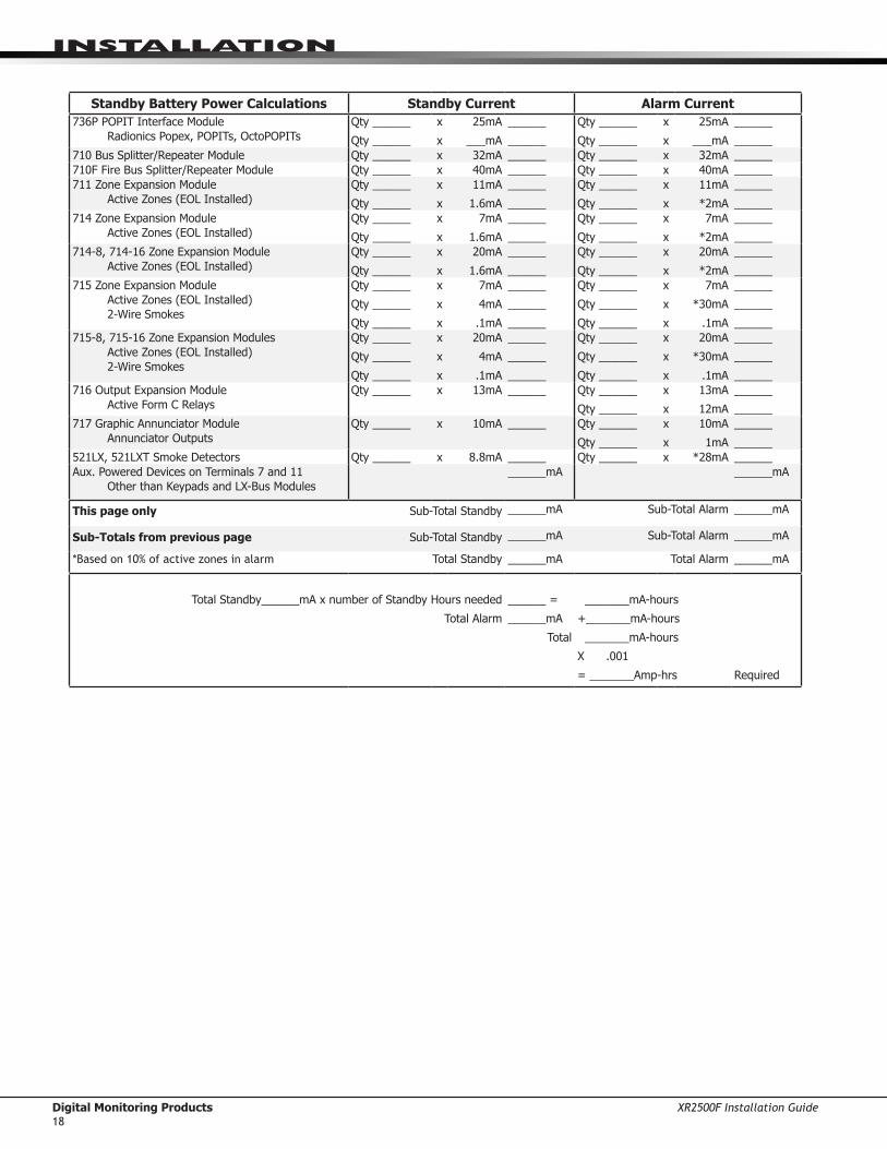
InstallatIon
Standby Battery Power Calculations Standby Current Alarm Current736P POPIT Interface Module
Radionics Popex, POPITs, OctoPOPITs Qty ______
Qty ______
x
x
25mA
___mA
______
______
Qty ______
Qty ______
x
x
25mA
___mA
______
______710 Bus Splitter/Repeater Module Qty ______ x 32mA ______ Qty ______ x 32mA ______710F Fire Bus Splitter/Repeater Module Qty ______ x 40mA ______ Qty ______ x 40mA ______711 Zone Expansion Module
Active Zones (EOL Installed)Qty ______
Qty ______
x
x
11mA
1.6mA
______
______
Qty ______
Qty ______
x
x
11mA
*2mA
______
______714 Zone Expansion Module
Active Zones (EOL Installed)Qty ______
Qty ______
x
x
7mA
1.6mA
______
______
Qty ______
Qty ______
x
x
7mA
*2mA
______
______714-8, 714-16 Zone Expansion Module
Active Zones (EOL Installed)Qty ______
Qty ______
x
x
20mA
1.6mA
______
______
Qty ______
Qty ______
x
x
20mA
*2mA
______
______715 Zone Expansion Module
Active Zones (EOL Installed) 2-Wire Smokes
Qty ______
Qty ______
Qty ______
x
x
x
7mA
4mA
.1mA
______
______
______
Qty ______
Qty ______
Qty ______
x
x
x
7mA
*30mA
.1mA
______
______
______715-8, 715-16 Zone Expansion Modules
Active Zones (EOL Installed) 2-Wire Smokes
Qty ______
Qty ______
Qty ______
x
x
x
20mA
4mA
.1mA
______
______
______
Qty ______
Qty ______
Qty ______
x
x
x
20mA
*30mA
.1mA
______
______
______716 Output Expansion Module
Active Form C RelaysQty ______ x 13mA ______ Qty ______
Qty ______
x
x
13mA
12mA
______
______717 Graphic Annunciator Module
Annunciator OutputsQty ______ x 10mA ______ Qty ______
Qty ______
x
x
10mA
1mA
______
______521LX, 521LXT Smoke Detectors Qty ______ x 8.8mA ______ Qty ______ x *28mA ______Aux. Powered Devices on Terminals 7 and 11
Other than Keypads and LX-Bus Modules______mA ______mA
This page only Sub-Total Standby ______mA Sub-Total Alarm ______mA
Sub-Totals from previous page Sub-Total Standby ______mA Sub-Total Alarm ______mA
*Basedon10%ofactivezonesinalarm Total Standby ______mA Total Alarm ______mA
Total Standby______mA x number of Standby Hours needed
Total Alarm
______ =
______mA
Total
_______mA-hours
+_______mA-hours
_______mA-hours
X .001
= _______Amp-hrs Required

XR2500F Installation Guide Digital Monitoring Products19
InstallatIon
11.8 Standby Battery SelectionTochoosethetypeandnumberofbatteriesneededfor24,60,or72hoursofstandbypowerbasedontheAmpHoursRequiredcalculationfromtheXR2500FPowerRequirementssection,performthefollowing:1.Selectthedesiredstandbyhoursrequiredfromthetablebelow:24,60,or72hours2.Selectthedesiredbatterysize:Model368(12VDC4.5Ah),Model369(12VDC7Ah),
Model367(12VDC7.7Ah),Model365(12VDC9Ah),Model366(12VDC18Ah).3.SelectaMax.AhAvailablenumberthatisjustgreaterthanthenumbercalculatedastheAmpHours
Required.4.InstallthenumberofbatteriesshowninthecorrespondingNo.ofBatteriesrequiredcolumn.Example: IftheAmpHoursRequiredcalculationequals22Ahfor24hoursofstandbytimeand4.5Ah
batteriesaredesired,installsix(6)Model368(12VDC,4.5Ah)batteries.For listed installations, all batteries shall be installed in a DMP Model 341, 349, 350, or 352S enclosure and all wiring shall run through conduit. The enclosure shall be installed to the left of the XR2500F enclosure to ensure Battery and AC wire separation.
24 hours of standby power4.5 Ah Batteries 7 Ah Batteries 7.7 Ah Batteries 9 Ah Batteries 18 Ah Batteries
Max. Ah Available
No. of Batteries
Max. Ah Available
No. of Batteries
Max. Ah Available
No. of Batteries
Max. Ah Available
No. of Batteries
Max. Ah Available
No. of Batteries
8 2 6 1 6 1 8 1 16 112 3 12 2 13 2 16 2 32 216 4 18 3 20 3 24 3 48 320 5 24 4 27 4 32 424 6 31 5 34 5 40 528 7 37 6 41 632 8 43 736 9 Note:48hoursisthetypicalbatteryrechargetimeforanyoftheNumberof
Batteriesshowninthissection.40 10
60 hours of standby power7 Ah Batteries 7.7 Ah Batteries 9 Ah Batteries 18 Ah Batteries
Max. Ah Available
No. of Batteries
Max. Ah Available
No. of Batteries
Max. Ah Available
No. of Batteries
Max. Ah Available
No. of Batteries
13 2 14 2 17 2 17 120 3 22 3 26 3 34 227 4 29 4 34 4 52 333 5 37 5 43 5 69 440 6 44 6 52 647 7 52 7 61 7 Note:48hoursisthetypicalbattery
rechargetimeforanyoftheNumberofBatteriesshowninthissection.
54 8 59 8 69 860 9 67 967 10
72 hours of standby power9 Ah Batteries 18 Ah Batteries
Max. Ah Available
No. of Batteries
Max. Ah Available
No. of Batteries
16 2 16 125 3 33 233 4 50 342 5 67 450 659 7 Note:72hoursisthetypicalbatteryrechargetimerequiredforanyoftheNumber
ofBatteriesshowninthissection.67 8
Note:IftheAmpHoursRequiredcalculationisgreaterthananyMax.AhAvailablenumbershownonatable,thenaddpowersupply(s)topowersomesystemdevicesallowingtheAmpHoursRequiredcalculationtobereduced.Seethe710/710FBusSplitter/RepeaterInstallationGuide(LT-0310).

Digital Monitoring Products XR2500F Installation Guide20
InstallatIon
Bell Output
12.1 Terminals 5 and 6Terminal5suppliespositive12VDCregulatedpowerforalarmbellsorhorns.Thisoutputcanbesteady,pulsed,ortemporaldependingupontheBellActionspecifiedinOutputOptions.Terminal6isthegroundreferenceforthebellcircuit.Thissupervisedoutputdetects10kOhmsorlessasnormal.Theindicatingappliancecansupplythisresistance.Ifusingahornorsiren,a1kOhm1/2WEOLresistor(provided)shouldbeaddedacrossthebellcircuittoprovidesupervision.SeetheNotificationAppliancesectionforalistofapprovednotificationappliancesandtheWiringDiagramsforconnections.
Keypad Bus
13.1 DescriptionXR2500Fpanelterminals7,8,9,and10areforthekeypadbus.InadditiontoFireCommandCentersandRemoteFireCommandCenters,youcanconnectuptofifteensupervisedkeypadsandmultipleunsupervisedkeypadstotheXR2500F.InadditiontoSecurityCommandkeypads,youcanalsoconnectanycombinationofzoneexpansionmodules,5845LXGlassbreakdetectors,and6155LXPIRstothedatabus.RefertothespecificdeviceInstallationsheetforthemaximumnumberofkeypadBusdevices.RefertothesectiontitledLX-BusforcompleteinformationabouttheLX-Bus4-pinheaderandexpansionslot. Note:DonotuseshieldedwireforLX-Bus/KeypadBuscircuits.
13.2 Terminal 7 - REDThisterminalsuppliespositive12VDCregulatedtopowerFireCommandCentersandzoneexpansionmodules.Terminal7alsosuppliespowerforanyauxiliarydevice.Thegroundreferenceforterminal7isterminal 10. Theoutputcurrentissharedwiththesmokepoweroutputonterminal11andZones9and10.Currentdrawforallconnecteddevicesmustnotexceedthepanelmaximumcurrentrating.SeePowerSupplyintheCompliancesectionformaximumcurrentinafirelistedapplication.
13.3 Terminal 8 - YELLOWTerminal8receivesdatafromkeypadsandzoneexpansionmodules.Itcannotbeusedforanyotherpurpose.
13.4 Terminal 9 - GREENTerminal9transmitsdatatokeypadsandzoneexpansionmodules.Itcannotbeusedforanyotherpurpose.
13.5 Terminal 10 - BLACKTerminal10isthegroundreferenceforFireCommandCenters,zoneexpansionmodules,andallauxiliarydevicesbeingpoweredbyterminal7.
13.6 J8 Programming ConnectionA4-pinheader(J8)isprovidedtoconnectakeypadwhenusingaDMPModel330ProgrammingCable.Thisprovidesaquickandeasyconnectionforpanelprogramming.YoumayalsousetheJ8ProgrammingHeadertoconnectKeypadBusdevices.Thisisanalternativetoconnectingkeypadbusdevicestoterminals7,8,9,and10.
13.7 OVC LEDTheOvercurrentLED(OVC)lightsRedwhenthedevicesconnectedtotheKeypadBusandLX-Bus(es)drawmorecurrentthanthepanelisratedfor.TheOVCislocatedaboveOutputs1and2onthepanelandturnsasteadyRedwhenlit.WhentheOVCLEDlightsRed,theLX-Bus(es)andKeypadbusareshutdown.

XR2500F Installation Guide Digital Monitoring Products21
InstallatIon
Smoke and Glassbreak Detector Output
14.1 Terminals 11 and 12Terminal11suppliespositive12VDCregulatedtopower4-wiresmokedetectorsandotherpowereddevices.ThisoutputcanbeturnedoffbytheuserforfivesecondsusingtheSensorResetUserMenuoptiontoallowlatcheddevicestoreset.Terminal12isthegroundreferenceforterminal11.
14.2 Current RatingTheOutputcurrentfromterminal11issharedwithterminals7,25,and27.Thetotalcurrentdrawofalldevicespoweredfromthepanelmustbeincludedwithterminal11calculationsandmustnotexceedthemaximumoutputrating.
Powered Zones for 2-Wire Smoke Detectors
15.1 Terminals 25–26 and 27–28Panelterminals25through28providetworesettableClassB,StyleA,2-wirepoweredzones.Forprogrammingpurposesthezonenumbersare9and10.
Note:Themaximumwirelengthforeitherzone9orzone10is3000feetusing18AWGor1000feetusing22AWG.Themaximumvoltageis14VDCandthemaximumnormalstandbycurrentis1.25mADC.Themaximumlineimpedanceis100Ohms.Themaximumshortcircuitcurrentis56mA.Whenusing725ZoneExpansionModules,useincluded,listed6.8kOhmEOLresistors.Thecompatibilityidentifierforthezonesusing725ZoneExpansionModulesisB.Whenusing715ZoneExpansionmodules,uselisted3.3kOhmEOLresistors,Model309.Forallotherzoneexpansionmodules,uselisted1.0kOhmModel310EOLresistors.ThecompatibilityidentifierforthezonesisA.
Note:Donotmixdetectorsfromdifferentmanufacturersonthesamezone.
Caution:PerformingaSensorResetmomentarilydropspowertothedevicesonZones9and10.Thepanelviewsthesezones(9and10)as“Open”whilethepowerisabsent.

Digital Monitoring Products XR2500F Installation Guide22
InstallatIon
15.2 Compatible 2-Wire Smoke Detector ChartManufacturer Model Detector
IDBase Base
IDDC
Voltage Range
# of Detectors (12V/24V)
Zone Expansion Modules
Panel Zones
Detection Systems DS230, DS230F B/A MB2W, MB2WL A 8.5-33 10 725
Detection Systems DS250, DS250TH B MB2W, MB2WL A 8.5-33 10/12715, 715-8, 715-16, 725
9 & 10
Detection Systems DS250HD B MB2W, MB2WL A 8.5-33 10715, 715-8,
715-169 & 10
Detection Systems DS260 B/A MB2W, MB2WL A 8.5-33 17 725
Detection SystemsDS282, DS282TH,
DS282THC, DS282THS
B 8.5-33 10/12715, 715-8, 715-16, 725
9 & 10
DMP/Hochiki SLR-835 HD-3 NS6-100 HB-55 8-35 7/14 725 9 & 10DMP/Hochiki SLR-835B HD-6 N/A 8-35 7/14 725 9 & 10
HochikiSLR-835B-2
SLR-835BH-2HD-6 N/A 8-35 14 725 9 & 10
Hochiki SLR-24, SLR-24H HD-3 NS4-220 HB-3 15-33 15 725 9 & 10
HochikiSIJ-24, DCD-190,
DCD-135HD-3 NS4-220 HB-3 15-33 15 725 9 & 10
Hochiki SLR-24, SLR-24H HD-3 NS6-220 HB-3 15-33 15 725 9 & 10Hochiki SIJ-24 HD-3 NS6-220 HB-3 15-33 20 725 9 & 10Hochiki DCD-190, DCD-135 HD-3 NS6-220 HB-3 15-33 16 725 9 & 10
Sentrol/ESL429AT, 521B, 521BXT,
521NB, 521NBXTS09A 6.5-20 12
715, 715-8, 715-16
9 & 10
Sentrol/ESL429C, 429CT,
521B/BXTS10A 8.5-33 12 725
Sentrol/ESL429CRT, 429CST,
429CSST, 521CRXTS11A 8.5-33 12 725
Sentrol/ESL711U, 712U,
713-5U, 713-6U, 721U, 721UT
S10A701E, 70-1U, 702E, 702U
S00 8.5-33 12 725
Sentrol/ESL 731U, 723U S11A701E, 701U, 702E, 702U,
702RE, 702RUS00 8.5-33 12 725
System Sensor 1400 A 8.5-35 10715, 715-8,
715-169 & 10
System Sensor 1151, 2151 A B110PL, B401 8.5-35 10/10715, 715-8, 715-16, 725
9 & 10
System Sensor 1451, 2451TH A B401, B401B 8.5-35 10715, 715-8,
715-169 & 10
System Sensor 1451DH A DH400 8.5-35 10715, 715-8,
715-169 & 10
System Sensor2100T, 2100B,
2100TB, 2100D, 2100TD
A 8.5-35 10715, 715-8,
715-169 & 10
System Sensor2400, 2400AT,
2400AIT, 2400THA 8.5-35 10
715, 715-8, 715-16
9 & 10
System Sensor 2451 AB401, B401B,
DH4008.5-35 10
715, 715-8, 715-16
9 & 10
System Sensor 2W-B, 2WT-B A 8.5-35 10715, 715-8,
715-169 & 10
System Sensor DH100P, DH100LP A 8.5-35 10715, 715-8, 715-16, 725
9 & 10
Table 6: Compatible 2-Wire Smoke Detectors

XR2500F Installation Guide Digital Monitoring Products23
InstallatIon
Protection Zones
16.1 Terminals 13–24Zones1to8(terminals13to24)ontheXR2500Fpanelareallgroundedburglaryzones.Forprogrammingpurposes,thezonenumbersare1through8.Listedbelowareterminal13to24connectionfunctions.
Terminal Function Terminal Function13 Zone1voltagesensing 19 Zone5voltagesensing14 GroundforZones1and2 20 GroundforZones5and615 Zone2voltagesensing 21 Zone6voltagesensing16 Zone3voltagesensing 22 Zone7voltagesensing17 GroundforZones3and4 23 GroundforZones7and818 Zone4voltagesensing 24 Zone8voltagesensing
Note:Zones1and2havebeenpre-wiredtothetwo866NACmodules.Allotherzonesareavailable.
Thevoltagesensingterminalmeasuresthevoltageacrossa1kOhmEnd-of-Lineresistortoground.UseDMPModel3111kOhmresistors.Drycontactsensingdevicescanbeusedinseries(normally-closed)orinparallel(normally-open)withanyoftheburglaryprotectionzones.
1K OhmNormallyClosed
1K OhmNormally Open
1K OhmCombination Normally Open
and Normally Closed
Figure 12: Protection Zone Wiring
16.2 Operational ParametersEachprotectionzonedetectsthreeconditions:Open,Normal,andShort.Listedbelowarevoltageandresistanceparametersforeachcondition:
Condition Resistance on zone Voltage on zone terminal Open over1300Ohms over2.0VDC Normal 600to1300Ohms 1.2to2.0VDC Short under600Ohms under1.2VDC
16.3 Zone Response TimeAconditionmustbepresentonazonefor500millisecondsbeforeitisdetectedbytheXR2500Fpanel.Ensuredetectiondevicesusedontheprotectionzonesareratedforusewiththisdelay.Zones1-10canalsobeprogrammedforafastresponsedelayof160milliseconds.
16.4 Keyswitch Arming ZoneUsingakeyswitchonanArmingtypezoneallowsyoutoarmanddisarmselectedareaswithouthavingtoenter a user code.

Digital Monitoring Products XR2500F Installation Guide24
InstallatIon
Dry Contact Relay Outputs
17.1 DescriptionTheXR2500FpanelprovidestwoprogrammableauxiliarySPDTrelayswiththetwoDMPModel305relaysinK6(Output1)andK7(Output2)andaModel431OutputHarnessontheJ26-pinHeader.EachrelayprovidesoneSPDTsetofcontactsthatcanbeoperatedbyanyofthefunctionslistedbelow:1) Activationbyzonecondition:Steady,Pulsing,Momentary,andFollow2) Activationby24-hour7-dayschedule:Oneonandoneofftimeadayforeachrelay3) ManualactivationfromtheSecurityCommandkeypadmenu4) Communicationfailure5) Armed area annunciation6) FireAlarm,FireTrouble,orSupervisory7) AmbushAlarm8) ExitandEntrytimers9) SystemReady10) Late to CloseRefertotheXR500SeriesProgrammingGuide(LT-0679)forspecificinformation.
17.2 Contact RatingTheModel305relaycontactsareratedfor1Ampat30VDC(allows.35powerfactor).ConnectauxiliarypowertotheRelayOutput1commonterminalbyinstallingthegrayharnesswiretoterminal7.Currentdrawforallconnecteddevicesmustnotexceedthepanelmaximumcurrentrating.
17.3 Output Harness WiringTheOutputHarnessispre-installedonthe6-pinheaderlabeledJ2.Output2usesthetopthreeprongs,andOutput1usesthebottomthreeprongs.Outputs1and2arepre-wiredtothe866NACmoduleslocatedwithintheXR2500Fenclosure.Forreference,thewireharnessandcontactlocationsareshownbelow:
Contact ColorOutput1normallyclosed VioletOutput1common GrayOutput1normallyopen OrangeOutput2normallyclosed BlueOutput2common WhiteOutput2normallyopen Yellow

XR2500F Installation Guide Digital Monitoring Products25
InstallatIon
J11 Annunciator Outputs
18.1 DescriptionThefourprogrammableannunciatoroutputscanbeprogrammedtoindicatetheactivityofthepanelzonesorconditionsoccurringonthesystem.Annunciatoroutputs do not provide a voltage but instead switch-to-groundavoltagefromanothersourceandareratedatamaximum30VDC@50mA.TheoutputscanrespondtoanyoftheconditionslistedintheDescriptionsectionofDryContactRelayOutputs.
18.2 Model 300 Harness WiringAccesstheopencollectoroutputsbyinstallingDMP300Harnessonthe4-pinheaderlabeledJ11.Theoutput locations are shown below. Note: For UL applications, devices connected to the outputs must be located within the same room as the panel.
Output Color Wire Output Color Wire3 Red 1 5 Green 34 Yellow 2 6 Black 4
18.3 Model 860 Relay ModuleConnectaModel860RelayModuletotheJ11ontheXR2500Fpaneltoproviderelaysforoutputs3-6.Usetheserelaysforelectricalisolationbetweenthealarmpanelandothersystemsorforswitchingvoltagetocontrolvariousfunctions.Powerissuppliedtotherelaycoilsfromasinglewireconnectedtothepanelauxiliarypowerterminal7.Themoduleincludesonerelayandprovidesthreeadditionalsocketsforexpansionofuptofourrelays.Mountthe860insidethepanelenclosureusingthe3-holepatternandplasticstandoffs.Refertothe860ModuleInstallSheet(LT-0484)asneeded.Model 305 Relay Contact Rating: 1Ampat30VDC(allows.35powerfactor)
J23 6-Pin Header
19.1 DescriptionTheXR2500FCommandProcessor™panelsupportsRS-232,LX-BusandWirelessBusexpansionoperation.Theseoperationscannotfunctionatthesametime.InstallajumperononepairofJ23headerstoindicatehowthepanelisprogrammedtooperate.RefertothetablebelowwheninstallingajumperonJ23.Whenajumperisinstalledormovedonthe6-pinheader,brieflyresetthepanelusingtheJ16jumpertoactivatethe selected operation.
J23 6-Pin HeaderLetter Operation
R StandardRS-232L LX-BusX WirelessBus
LEDsXmitRec
J22LX
J23
J21
RS-232RLX Overcurrent
(OVC) LED
Figure 14: J23 6-Pin Header

Digital Monitoring Products XR2500F Installation Guide26
InstallatIon
J22 LX-Bus Expansion Connector20.1 Description
J22LX-BusandJ21RS-232connectorscannotbeusedatthesametime.EitheruseJ21toconnectaserialdeviceforPCLogReporting,oruseJ22toconnectanLX-BusorWirelessdevice.ThisisdeterminedbywhereyouinstallthejumperonJ236-PinHeader.ResetthepanelusingJ16jumpertoactivateselectedJ23operation.SeetheConnectingLX-BusandKeypadBusDevicessectionformaximumwiringdistances.Note:DoNOTuseshieldedwirewhenusingtheLX-Bus.DoNOTconnectthewiresfromthe4-wireharnessto the panel terminals.
20.2 LX-Bus Interface CardsRefertothefollowingtablestoidentifyzonelocationsandnumbersrelativetoJ22operation.
J22 LX-Bus Enabled
AND
One Interface Card
OR
461 Adaptor Card and Multiple Interface
CardsLX-Bus Zone Numbers LX-Bus Zone Numbers LX-Bus Zone Numbers
1 500-599 2 600-699 2 (A) 600-6993(B) 700-7994 (C) 800-8995 (D) 900-999
J22 LX-Bus NOT
Enabled
One Interface Card
OR
461 Adaptor Card and Multiple Interface
CardsLX-Bus Zone Numbers LX-Bus Zone Numbers
1 500-599 1 (A) 500-5992(B) 600-6993(C) 700-7994 (D) 800-8995(E) 900-999
20.3 LX-Bus LEDsThetwoLEDs,locatednearthebottom-rightcornerofJ21indicatedatatransmissionandreceipt.ThetopLEDflashesgreentoindicatethepanelistransmittingLX-Busdata.ThebottomLEDflashesyellowtoindicatethepanelisreceivingLX-Busdata.
20.4. OVC LEDTheOvercurrentLED(OVC)lightsRedwhenthedevicesconnectedtotheKeypadBusandLX-Bus(es)drawmorecurrentthanthepanelisratedfor.TheOVCislocatedaboveOutputs1and2onthepanelandturnsasteadyRedwhenlit.WhentheOVCLEDlightsRed,theLX-Bus(es)andkeypadbusshutdown.
J21 Serial Connector21.1 Description
Note:J22LX-BusandJ21RS-232connectorscannotbeusedatthesametime.EitheruseJ21toconnectaserialdevice,oruseJ22toconnectanLX-BusorWirelessdevice.ThisisdeterminedbywhereyouinstallthejumperontheJ236-PinHeader.ResetthepanelusingJ16jumpertoactivateselectedJ23operation.Themaximumlineimpedanceis100Ohms.ToenableJ21tooperateinRS-232modeplaceajumperonthetwopinsnexttotheletter“R”ontheJ236-Pinheader.TheSerialConnectorallowstheXR2500FpaneltotransmitPCLogReportsdirectlytoanRS-232device.
21.2 Serial Connector LEDsThetwoLEDs,locatednearthebottom-rightcornerofJ21indicatedatatransmissionandreceipt.ThetopLEDflashesgreentoindicatethepanelistransmittingserialdata.ThebottomLEDflashesyellowtoindicatethepanelisreceivingserialdata.

XR2500F Installation Guide Digital Monitoring Products27
InstallatIon
J1 Ethernet Connector
22.1 DescriptionTheJ1EthernetConnectorisavailabletoconnectdirectlytoanEthernetnetworkusingastandardpatchcable.Themaximumlineimpedanceis100Ohms.
J1Ethernet
Link LEDActivity LED
Figure 15: J1 Header and LEDs
22.2 Ethernet LEDsThetwoLEDs,locatedtotheleftofJ1EthernetConnector,indicatenetworkoperation.Thetop,ActivityLEDflashesgreentoindicatethenetworktrafficisgood.Thebottom,LinkLEDflashesyellowtoindicatemessagesarebeingsentandreceived.
Reset and Tamper Headers
23.1 J16 Reset Header TheresetheaderislocatedjustabovetheterminalstripontherightsideofthecircuitboardandisusedtoresettheXR2500Fmicroprocessor.Toresetthepanelwhenfirstinstallingthesystem,installtheresetjumperbeforeapplyingpowertothepanel.AfterconnectingtheACandbattery,removetheresetjumper.
Toresetthepanelwhilethesystemisoperational,forexample,priortoreprogramming,installtheresetjumperwithoutpoweringdownthesystem.Removetheresetjumperafteroneortwoseconds.
Afterresettingthepanel,beginprogrammingwithin30minutes.Ifyouwaitlongerthan30minutes,youmustresetthepanelagain.
J6 Interface
Card Expansion Connector
Momentarily place the Reset jumper over both of the J16 pins to reset the panel.
AC
1 2 3 4 5 6 7 8 10 11 12 13 14 15 16 17 18 199 20 21 22 23 24 25 26 27 28
+B BELLGND SMK GNDRED YEL GRN BLK Z1 Z2 Z3 Z4 Z5 Z6 Z7 Z8 Z9+ Z9– Z10+Z10–AC –B GND GND GNDGND
K6 K7
Output 1 Output 2
J3Phone Line
J10
J22LX-Bus
Battery Start
J23
J21
RS-232Power LED
J8PROG
J4Tamper
J16Reset
Out1
Out2
Outputs 3-6
J113 4 5 6
J2
J1Ethernet
RLX
OVC
Link LEDActivity LED
Figure 16: XR2500F Panel Showing the Reset Jumper
23.2 J4 Tamper Header TheJ4headerisforusewiththeoptionalDMP306TamperHarness.Theharnessconnectstooneormoretamperswitchesmountedinsidethepanelenclosuretosuperviseagainstunauthorizedenclosureopeningorremoval.Refertothewiringdiagramontheenclosuredoorforcorrecttamperswitchwiring.
How the Tamper WorksIftheenclosureisopenedorremovedwhileoneormoreofthesystemareasarearmed,apaneltamperalarmisindicated.Ifallareasaredisarmed,apaneltampertroubleisindicated.

Digital Monitoring Products XR2500F Installation Guide28
InstallatIon
Listed Compliance Specifications
24.1 IntroductionForapplicationsthatmustconformtoalocalauthoritiesinstallationstandardoraNationalRecognizedTestingLaboratorycertificatedsystem,pleaseseethefollowingsections.
Universal UL Burglary Specifications
25.1 IntroductionTheprogrammingandinstallationspecificationscontainedinthissectionmustbecompletedwheninstallingtheXR2500Fpanelinaccordancewithanyburglarystandards.Additionalspecificationsmayberequiredbyaparticularstandard.SeetheXR500ProgrammingGuide(LT-0679).
25.2 WiringAllwiringmustbeinaccordancewithNEC,ANSI/NFPA70,ANSI/UL681.Alltransformerwiresmustbeinstalled in conduit.
25.3 Control Outside of Protected AreaAPotterEVDorSentrol5402shouldbeusedinplaceofalinedcabinetwhenthepanelisinstalledoutsideoftheprotectedarea.Frontandreartamperswitchesarerequired.RefertothesystemwiringdiagramandFigure2.
25.4 Police Station Phone NumbersThedigitaldialertelephonenumberprogrammedforcommunicationmustnotbeapolicestationphonenumber.
25.5 Bypass ReportsTheBypassReportsoptionmustbeprogrammedasYESforalllistedburglaryapplications.
25.6 System MaintenanceToensurecontinuoussatisfactoryoperationofanyalarmsystem,properinstallationandregularmaintenancebytheinstallingalarmcompanyandfrequenttestingbytheenduserisessential.Offeringamaintenanceprogramandacquaintingtheuserwiththecorrectproceduresforsystemuseandtestingisalsotheresponsibilityoftheinstallingalarmcompany.
25.7 Listed ReceiversOperationhasbeenverifiedwiththeDMPSCS-1R,Sur-GardSG-HLR2-DG,FBIICP220PB,Osborne-HoffmanQuick-Alert,andRadionicsD6500receivers.Itistheinstaller’sresponsibilitytoverifycompatibilitybetweentheXR2500Fandthereceiverusedduringinstallation.Theinstallershallverifythecompatibilityofthereceiver and the system on a yearly basis.
25.8 Power Supply SupervisionForcommercialburglaryapplicationsthepowersupplyforalllocalbellsshallbeunder24-hourprotection.RefertotheSecondaryPowerSupplysectioninthisdocument.
25.9 Wireless TamperTheZoneInformationDisarmedOpenMessagetoTransmitmustbeprogrammedTrouble(T).(NotapplicabletoANSI/UL1023).
25.10 Wireless External ContactWhenused,theExternalContactof1101or1102mustbeprogrammedNormallyClosed.
25.11 Wireless Supervision TimeTheZoneInformationSupervisionTimecannotbesetto0(zero).
25.12 Detect Wireless JammingTheDetectWirelessJammingoptionmustbeprogrammedYES.(NotapplicabletoANSI/UL1023).

XR2500F Installation Guide Digital Monitoring Products29
InstallatIon
Area Information26.1 Ownership
The control unit system shall be under one ownership.
26.2 AnnunciationTheSystemshallbeinstalledsothatwhenarminganyareafromanykeypad,thelocalbellshallannunciate.
26.3 Trouble DisplayTheStatusListprogrammingshallbesettoannunciatealltroublemessagesatallkeypads.
26.4 Closing WaitTheClosingWaitoptionmustbeprogrammedYES.
26.5 Local Bell SupervisionWhenalocalbellisemployed,thepowersupplyforthebellshallbeunder24-hourprotection.Properpersonnelformaintenanceorsecurityofthesystemshallbeabletodisarmthatarea.
Household Burglar-Alarm System Units ANSI/UL 1023
27.1 Audible DevicesAtleastonelistedaudibledevice(AdemcoAB12M)ratedtooperateoverthevoltagerateof11.7VDCto12.8VDCandratedat85DBminimummustbeused.
27.2 Auxiliary CircuitsAtleastoneburglaryalarminitiatingdeviceshallbeusedonthesystem.Ifthevoltageforthedeviceisappliedbythecontrolunittheburglaryalarminitiatingdeviceshallberatedtooperateovertherangeof11.5VDCto12.7VDC.
27.3 Bell CutoffTheBellCutofftimecannotbelessthanfiveminutes.
27.4 Entry DelayThe maximum entry delay used must not be more than 45 seconds.
27.5 Exit DelayThemaximumexitdelayusedmustnotbemorethan60seconds.
27.6 Weekly TestThe product should be tested weekly.
27.7 Wireless Audible Annunciation OptionTheWirelessAudibleoptionmustbeselectedasDAYforresidentialapplications.
Central-Station and Proprietary Burglar-Alarm Units ANSI/ UL 1610 AND ANSI/UL 1076
28.1 Opening/Closing ReportsTheOpening/ClosingReportsoptionmustbeprogrammedasYES..
28.2 Closing WaitTheClosingWaitoptionmustbeprogrammedYES.
28.3 Entry DelayThemaximumentrydelayusedmustnotbemorethan60seconds.
28.4 Exit DelayThemaximumexitdelayusedmustnotbemorethan60seconds.

Digital Monitoring Products XR2500F Installation Guide30
InstallatIon
28.5 Proprietary DialerTheModelXR2500Fprovidesproprietaryservicewhenconfiguredasadigitaldialer.
28.6 DACT Central StationDACTCentralStationservicecanbeprovidedunderbyaddinganAdemcoAB12Mbellandbellhousing.
28.7 Bell CutoffTheBellCutofftimecannotbelessthan15minutes.
28.8 Standard or Encrypted Line SecurityStandardLineSecurityisprovidedwhenconfiguredasaPath1NETsystemusinganXR500Npanel.TheNETCheck-intimemustbesetto06minutesorRDM.WhenprogrammedforStandardLineSecurity,ExitTimeRestartisdisabled.Whenadialerisrequiredfor06minutecheck-intime,anattackresistantenclosure(DMPModel350A)isrequired.Whenthecheck-intimeissettoanumberlessthan200seconds,anattackresistant enclosure is not required.
ToprovideEncryptedLinesecurity,installanXR500Epanel.
ForEncryptedLinesecurityoperation,communicationbetweenthePremiseandSupervisingStationprovides128bitencryptionwhenusinganXR500EpaneloranXR500panelwithaniCOM-EEncryptedNetworkAlarmRouter.
TheModelXR500SeriesProtectedPremisesControlUnitissuitableforStandardLineSecurityservicewhenconfiguredforNETcommunicationwithSCS-1Rreceivingsystem.Thisconfigurationisapprovedforthefollowing:
AMCX-CentralStationAlarmUnits APOU-ProprietaryAlarmUnits
28.9 Wireless Audible Annunciation OptionTheWirelessAudibleoptionmustbeselectedasANYforcommercialapplications.
28.10 Model 463G CELL Only, Standard or Encrypted Line Security StandardorEncryptedLineSecurityisprovidedwhenprogrammedusingCELLwithnobackup.XR500cellularcommunicationisusedasprimarywitha3minutecheck-inwhenarmedordisarmed.
Path 1 programmingCommType:=CELL Checkin:=3minute
Path Type: = Primary FailTime:=3minute
Encrypt:=NOorYES* TestRpt:=NO
SubCode:=NOorYES
*ForEncryptedLineSecurity,programaPassphraseinNetworkOptions.

XR2500F Installation Guide Digital Monitoring Products31
InstallatIon
28.11 Model 463G NET with CELL as Alternate Primary and Dialer Backup, Standard or Encrypted Line Security StandardorEncryptedLineSecurityisprovidedusingNETcommunicationwithCELLasanalternateprimaryandwithdigitaldialerasabackup.XR500networkcommunicationisusedasprimarywitha6minutecheck-inwhenarmed,andarandomcheck-inovera60minuteperiodwhendisarmed.CELListhebackuppathandsettodailytest.ShouldtheNETprimarypathbecomedisabled,CELLadaptsthesamecheck-intimeprogrammedfortheprimarycommunicationandbecomesanalternateprimarypath.ThedialerpathisusedasthebackupifbothNETandCELLfailtoreceiveacknowledgementfromthereceiver.ThismethodofoperationcausestheCELLalternateprimarytoadapttothe6minuteNETprimarycheck-inratewhentheNETprimaryisunavailablemaintaininglinesupervisionandprecludestheneedforacentralstationrunnertorespondtotheNETprimaryfailure.
Path 1 programming Path 2 programming Path 3 programming CommType:=NET CommType:=CELL Comm Type: = DD Path Type: = Primary PathType:=Backup
(operates as alternate primary)
PathType:=Backup(operates as second method)
TestRpt:=NO TestRpt:=YES TestRpt:=YESCheckin:=6minute,orRND(random)
Test Freq: = Daily Test Freq: = Daily
FailTime:=6minute,orRND(random)
Checkin: = ADAPT DuplicateAlarms:=YES
Encrypt:=NOorYES* Encrypt:=NOorYES*SubCode:=YES SubCode:=Shared
*ForEncryptedLineSecurity,programaPassphraseinNetworkOptions.
28.12 Model 463G NET with CELL as Backup and Adaptive Primary, Standard or Encrypted Line Security StandardorEncryptedLineSecurityisprovidedwhenprogrammedusingNETcommunicationandCELLasbackup and as needed adapts and takes over as primary. XR500 network communication is used as primary witha6minutecheck-inwhenarmed,andarandomcheck-inovera60minuteperiodwhendisarmed.CELListhebackuppathandsettodailytest.Shouldtheprimarypathbecomedisabled,theCELLadaptstoaspecial3minutecheck-intimeandbecauseofthatcheck-inratebecomestheprimarywithouttherequirementofabackup.ThismethodofoperationcausestheCELLbackuptoadapttothe3minutecheck-inratewhentheNETprimaryisunavailablebecomingastandaloneprimarywithouttheneedforabackup.ThismaintainslinesupervisionandprecludestheneedforacentralstationrunnertorespondtotheNETprimaryfailure.
Path 1 programming Path 2 programming CommType:=NET CommType:=CELLPath Type: = Primary PathType:=Backup(operatesassecond
method) TestRpt:=NO TestRpt:=YESCheckin:=6minute,orRND(random)
Test Freq: = Daily
FailTime:=6minute,orRND(random)
Checkin:=ADAPT3
Encrypt:=NOorYES* Encrypt:=NOorYES*SubCode:=YES DuplicateAlarms:=YES
SubCode:=Shared*ForEncryptedLineSecurity,programaPassphraseinNetworkOptions.

Digital Monitoring Products XR2500F Installation Guide32
CoMPlIanCe
Holdup Alarm Units ANSI/UL 636
29.1 ANSI/UL 1610 RequiredTheprogrammingandinstallationspecificationscontainedinthissectionmustbecompletedinadditiontoANSI/UL1610SpecificationswheninstallingaModel1142withaModelXR500Seriespanel.
29.2 1100X Wireless ReceiverTheModel1100XWirelessReceiverinconjunctionwiththeModel1142HoldupAlarmTransmittermustbeinstalled in the system.
29.3 Wireless Supervision TimeTheZoneInformationSupervisionTimemustbeamaximumof240minutes.
29.4 LED DisplayTheLEDOperationoptiondisplaymustbesettoNOwhenusingaModel1142HoldupAlarmTransmitter.
29.5 Jamming DetectionTheDetectWirelessJammingoptionmustbesettoYES.
29.6 Local AlarmTheBellActionforaPN(Panic)typezonemustbeprogrammedasN(None).
29.7 Message to TransmitTheArmedOpenandArmedShortmessagesforaPN(Panic)typezonemustbeprogrammedtoA(Alarm).
29.8 Wireless Audible Annunciation OptionTheWirelessAudibleoptionmustbeselectedasANYforcommercialapplications.
Digital Burglar Alarm Communicator System Units ANSI/ UL 1635
30.1 System Trouble DisplayTheStatusListDisplaymustincludeatleastonekeypadthatdisplayssystemmonitortroubles.
30.2 Digital Dialer Telephone NumberBothprogrammedtelephonenumbersmustbeginwithaP.
30.3 Test TimeTheTestTimeoptionmustbeprogrammedsothattheXR2500Fsendsareportonceevery24hours.
30.4 Closing WaitTheClosingWaitoptionmustbeprogrammedYES.
Police Station Connected and Local Burglar Alarm Units
ANSI/UL 36531.1 System Trouble Display
TheStatusListDisplaymustincludeatleastonekeypadthatdisplayssystemmonitortroubles.
31.2 Entry DelayThemaximumentrydelayusedmustnotbemorethan60secondswhenusingModel350Aor350HAttackhousing.
31.3 Exit DelayThemaximumexitdelayusedmustnotbemorethan60seconds.

XR2500F Installation Guide Digital Monitoring Products33
CoMPlIanCe
31.4 BellAlocalaudiblesignalappliancemustbeusedsuchasAdemcoAB12Mbellandbellhousing.Thealarmhousingforamercantilealarmsystemwithoutaremotealarmtransmissionconnectionshallbemountedontheoutsideofthebuilding,visiblefromapublicstreetorhighway.Itshallbeaccessibleforexaminationandrepair.Itshallalsobelocatednotmorethanfourstoriesabovethestreetlevelunless:a)Asecondalarmsoundingdeviceandhousing,intendedforoutsideservice,ismountedadjacenttothepremisesorareaofthebuildinginwhichthealarmsystemisinstalledorb)Asecondalarmsoundingdevice,intendedforinsideservice,ismountedwithinthepremises.Ineithercase,theoutsidealarmsoundingdeviceandhousingmaybemountedashighastheseventhfloor.
31.5 Bell CutoffTheBellCutofftimecannotbelessthan15minutes.
31.6 Automatic Bell TestTheAutomaticBellTestoptionmustbeprogrammedasYES.
31.7 Standard or Encrypted Line SecurityStandardLineSecurityisprovidedwhenconfiguredasaPath1NETsystemusinganXR500NpaneloranXR500panelwithaniCOM™NetworkAlarmRouter.TheNETCheck-intimemustbesetto06minutesorRDM.WhenprogrammedforStandardLineSecurity,ExitTimeRestartisdisabled.Whenadialerisrequiredfor06minutecheck-intime,anattackresistantenclosure(DMPModel350A)isrequired.Whenthecheck-intimeissettoanumberlessthan200seconds,anattackresistantenclosureisnotrequired.ToprovideEncryptedLinesecurity,installanXR500EpaneloranXR500panelwithaniCOM-E™EncryptedNetworkAlarmRouter.ForEncryptedLinesecurityoperation,communicationbetweenthePremiseandSupervisingStationprovides128bitencryptionwhenusinganXR500EpaneloranXR500panelwithaniCOM-EEncryptedNetworkAlarmRouter.
31.8 Wireless Audible Annunciation OptionTheWirelessAudibleoptionmustbeselectedasANYforcommercialapplications.
31.9 Model 463G CELL Only, Standard or Encrypted Line Security StandardorEncryptedLineSecurityisprovidedwhenprogrammedusingCELLwithnobackup.XR500cellularcommunicationisusedasprimarywitha3minutecheck-inwhenarmedordisarmed.
Path 1 programmingCommType:=CELL Checkin:=3minute
Path Type: = Primary FailTime:=3minute
Encrypt:=NOorYES* TestRpt:=NO
SubCode:=NOorYES
*ForEncryptedLineSecurity,programaPassphraseinNetworkOptions.

Digital Monitoring Products XR2500F Installation Guide34
CoMPlIanCe
31.11 Model 463G NET with CELL as Alternate Primary and Dialer Backup, Standard or Encrypted Line Security StandardorEncryptedLineSecurityisprovidedusingNETcommunicationwithCELLasanalternateprimaryandwithdigitaldialerasabackup.XR500networkcommunicationisusedasprimarywitha6minutecheck-inwhenarmed,andarandomcheck-inovera60minuteperiodwhendisarmed.CELListhebackuppathandsettodailytest.ShouldtheNETprimarypathbecomedisabled,CELLadaptsthesamecheck-intimeprogrammedfortheprimarycommunicationandbecomesanalternateprimarypath.ThedialerpathisusedasthebackupifbothNETandCELLfailtoreceiveacknowledgementfromthereceiver.ThismethodofoperationcausestheCELLalternateprimarytoadapttothe6minuteNETprimarycheck-inratewhentheNETprimaryisunavailablemaintaininglinesupervisionandprecludestheneedforacentralstationrunnertorespondtotheNETprimaryfailure.
Path 1 programming Path 2 programming Path 3 programming CommType:=NET CommType:=CELL Comm Type: = DD Path Type: = Primary PathType:=Backup(operates
as alternate primary) PathType:=Backup(operates as second method)
TestRpt:=NO TestRpt:=YES TestRpt:=YESCheckin:=6minute,orRND(random)
Test Freq: = Daily Test Freq: = Daily
FailTime:=6minute,orRND(random)
Checkin: = ADAPT DuplicateAlarms:=YES
Encrypt:=NOorYES* Encrypt:=NOorYES*SubCode:=YES SubCode:=Shared
*ForEncryptedLineSecurity,programaPassphraseinNetworkOptions.
31.12 Model 463G NET with CELL as Backup and Adaptive Primary, Standard or Encrypted Line Security StandardorEncryptedLineSecurityisprovidedwhenprogrammedusingNETcommunicationandCELLasbackup and as needed adapts and takes over as primary. XR500 network communication is used as primary witha6minutecheck-inwhenarmed,andarandomcheck-inovera60minuteperiodwhendisarmed.CELListhebackuppathandsettodailytest.Shouldtheprimarypathbecomedisabled,theCELLadaptstoaspecial3minutecheck-intimeandbecauseofthatcheck-inratebecomestheprimarywithouttherequirementofabackup.ThismethodofoperationcausestheCELLbackuptoadapttothe3minutecheck-inratewhentheNETprimaryisunavailablebecomingastandaloneprimarywithouttheneedforabackup.ThismaintainslinesupervisionandprecludestheneedforacentralstationrunnertorespondtotheNETprimaryfailure.
Path 1 programming Path 2 programming CommType:=NET CommType:=CELLPath Type: = Primary PathType:=Backup(operatesassecond
method) TestRpt:=NO TestRpt:=YESCheckin:=6minute,orRND(random)
Test Freq: = Daily
FailTime:=6minute,orRND(random)
Checkin:=ADAPT3
Encrypt:=NOorYES* Encrypt:=NOorYES*SubCode:=YES DuplicateAlarms:=YES
SubCode:=Shared
*ForEncryptedLineSecurity,programaPassphraseinNetworkOptions.

XR2500F Installation Guide Digital Monitoring Products35
CoMPlIanCe
Police Station Connected and Local Burglar Alarm Units ANSI/UL 609
32.1 MercantileForMercantileandPoliceStationConnectoperationtheModelXR500SeriesmustbemountedinanAttackResistantHousing,(DMPModel350Aor350H).
32.2 Entry DelayThemaximumentrydelayusedmustnotbemorethan60secondswhenusingtheModel350Aor350Hhousing.
32.3 Exit DelayThemaximumexitdelayusedmustnotbemorethan60seconds.
32.4 BellAlocalaudiblesignalappliancemustbeusedsuchasAdemcoAB12Mbellandbellhousing.Inamercantileburglaralarmsystem,amercantilealarmsoundingdevicelocatedwithinabuildingbutoutsidetheprotectedarea,isacceptable,provideditisratedforoutsideserviceandalarmconditionsaretransmittedto:a)Thedispatchlocationofthelawenforcementagencyhavingjurisdictionovertheprotectedpropertyorb)AcentralstationorresidentialmonitoringstationcomplyingwiththeStandardforCentralStationAlarmServices,UL827.Inamercantileburglaralarmsystem,analarmsoundingdevicelocatedwithintheareaofgreatestprotection,oroutsidetheareaofgreatestprotectionbutwithinanareaprotectedbyanalarmsystemandthatsharesacommoncontrolunitwiththesysteminstalledintheareaofgreatestprotection,isacceptableprovideditisratedforinsideserviceandalarmconditionsaretransmittedto:a)Thedispatchlocationofthelawenforcementagencyhavingjurisdictionovertheprotectedpropertyorb)AcentralstationorresidentialmonitoringstationcomplyingwiththeStandardforCentralStationAlarmServices,UL827.Aninsidesoundingdeviceshallbemountedatleast10feet(3.05m)abovethefloororatthesurfaceoftheceiling.Whenthereisfixedconstructionwithintheareathatcouldprovideaccessforanintruder,thealarmsoundingdeviceshallalsobemountedatleast4feet(1.2m),asmeasuredhorizontally,awayfromtheedgesofthefixedconstructionoratleast10feet(3.05m)aboveitsoastominimizeaccessbyanintruder.
32.5 Wireless Audible Annunciation OptionTheWirelessAudibleoptionmustbeselectedasANYforcommercialapplications.
Access Control System Units ANSI/UL 294
33.1 Panel DesignationTheXR2500Fisdesignatedasastandaloneunit.
33.2 Compatible DevicesThefollowingdevicesarecompatiblewiththeXR2500Fpanels.Access Control733 Wiegand Interface Module Proximity reader connector734 Wiegand Interface Module Programmable proximity reader connectorOP-08CB Motion Detector Infrared sensor.* PB-2 REX Button Exit control push buttonPP-6005B Proxpoint Plus® Reader Proximity readerMP-5365 Miniprox® Reader Slimline proximity readerPR-5455 ProxPro® II Reader Long range reader with sounderMX-5375 Maxi-Prox™ Reader Long range reader compatible with 1351 Prox Pass* This device has not been investigated and shall not be used in listed installations.

Digital Monitoring Products XR2500F Installation Guide36
CoMPlIanCe
Universal Fire Alarm Specifications
34.1 IntroductionTheprogrammingandinstallationspecificationscontainedinthissectionmustbecompletedwheninstallingtheModelXR2500FinaccordancewithanyoftheANSI/ULorNFPAfirestandards.Additionalspecificationsmayberequiredbyaparticularstandard.SeetheXR500SeriesProgrammingGuide(LT-0679).
34.2 WiringAllwiringmustbeinaccordancewithNEC,ANSI/NFPA70.
34.3 TransformerUsethesupplied16VAC56VAtransformer.
34.4 End-of-Line ResistorTheDMPModel3101KOhmEOLresistorshouldbeusedonall1KOhmEOLfirezones.
34.5 System Trouble DisplayTheStatusListDisplaymustincludeatleastonekeypadthatdisplayssystemmonitortroubles.
34.6 Fire DisplayTheStatusListDisplaymustincludeatleastonekeypadthatdisplaystroublesandalarmsonfiretypezones.
34.7 Police Station Phone NumberThedigitaldialertelephonenumberprogrammedforcommunicationmustnotbeapolicestationphonenumber,unlessthatphonenumberisspecificallyprovidedforthatpurpose.
34.8 System MaintenanceToensurecontinuoussatisfactoryoperationofanyalarmsystem,properinstallationandregularmaintenancebytheinstallingalarmcompanyandfrequenttestingbytheenduserisessential.Offeringamaintenanceprogramandacquaintingtheuserwiththecorrectproceduresforsystemuseandtestingisalsotheresponsibilityoftheinstallingalarmcompany.
34.9 Audible AlarmFireTypezonesmustbeprogrammedtoactivateanaudiblealarm.TheBellActionforFireTypezonesmustnotbeprogrammedas“N”.
34.10 Fire Zone ProgrammingIfaretarddelayisusedonawaterflowzone,itcannotexceed90secondsandanyretarddelayinthewaterflowinitiatingdevicesmustbesubtractedfromthe90secondsallowed.Theretarddelayshouldnotbeusedonazonewithsmokedetectors.
34.11 Style D ZonesIfrequired,theDMP869DualStyleDInitiatingModuleprovidesforconnectionoftwoStyleDzonestotheModelXR2500F.Seethe869InstallationGuide(LT-0186)andthisguideforwiringinformation.
34.12 Listed ReceiversUsetheDMPSCS-1R(SDLC),Sur-GardSG-HLR2-DG(CID),FBIICP220PB(CID),andOsborne-HoffmanQuick-Alert(CID)receivers.

XR2500F Installation Guide Digital Monitoring Products37
CoMPlIanCe
Control Units for Fire-Protective Signaling Systems ANSI/UL 864, NFPA 72
35.1 Power SupplyFor listed installations, the total current combined from Auxiliary and Bell Power cannot exceed: 1.2 Amps with a 56 VA transformer; .5 Amp Max for Auxiliary Power and .7 Amp Max for Bell Combined total current from Terminals 7, 11, 25, and 27 cannot exceed 1.2 Amps.
35.2 Zone Restoral ReportsTheRestoralReportsoptionmustbeselectedasYESorDisarm..
35.3 Power Fail DelayThePowerFailDelayoptionmustbeselectedasrequiredbytheserviceofthepanel.ForCentralStationorRemoteStationservice:1.
35.4 Sprinkler SupervisoryAnyzoneusedforsprinklersupervisorymustbeprogrammedwith“SPRINKLRXXX”asthezonename.Thelastthreecharactersinthezonenamemaybeassignedanumbertoidentifythezone.TheModel893ADualPhone Line Module must be used on all sprinkler supervisory systems.
35.5 DACT SystemsTwophonelinesmustbeused.Thetwophonelinescannotbegroundstartorpartylines.The893ADualPhoneLineModuleisusedtoprovidetwophonelineconnectionstothesystem.The2NDPhoneLinecommunication option must be selected as DD.
Twodifferentphonenumbersmustbeprogrammedfordigitalcommunication.TheTestTimeoptionmustbeprogrammedsothattheXR2500Fsendsareportevery24hours.
35.7 Local Protective Signaling SystemsTheDMPModel865,866,or867NotificationCircuitModulemustbeusedonthebellcircuitfordetectionofshortsandgrounds.Seethisguideforwiringdiagrams.AnyburglaryorotheroffpremisescommunicationmustbedonewiththeModel893ADualPhoneLineModule.Forlocalcommercialfireinstallations,the893Ais required.
35.8 Remote Station Protective Signaling SystemsYoumustprovide60hoursofstandbybattery.Seethisguideforstandbybatterycalculations.TwoRadionicsModelD127ReversingRelayModulesprovidetworeversingpolaritytelephoneconnections.SeetheD127InstallationInstructionsheetforwiringdetails.ADMPModel893Aisusedtoprovidetwolinedialercommunication.
35.9 Fire Protective Signaling Systems using Internet/Intranet NetworksTheXR2500FpanelmustbeprogrammedasdescribedbelowforFireProtectiveSignalingSystemsusingNETCommunication Type. • SUBCODEmustbeprogrammedasYES • FAILTIMEmustbeprogrammedas5• CHECKINmustbeprogrammedas3 • SENDCOMMTRBLmustbeprogrammedasYES
35.10 Combination SystemsForcombinationfireandburglarysystems,poweredburglarydevices(PIR,Glassbreak,etc.)mustbepoweredfromaseparatelistedpowersupply(DMPModel505-12).Thisrequirementisnotneededfornon-poweredburglarydevices(doorcontacts,etc.)whichonlyconnecttothezoneinputofzoneexpandersorkeypads.RefertoPoweredBurglaryDevicesinthisdocument.
Forcombinationfireandburglarysystems,burglarysoundingdevicessuchassirensandbellsmustbeenergizedusingpanelrelays,860relays,or716relays.ProgrammingtheoutputtoactivatetherelaymustoccurusingtheBurglaryBellOutputoptioninAreaInformationorbytheAlarmActionoutputoptionofZoneInformation.TheBurglaryBellActionoptionofthepanelBellOptionsmustbeprogrammedasNone.
35.11 Remote AnnunciatorsAtleastoneModel630FRemoteAnnunciatormustbeusedonthesystem.Allfirealarms,firetroublesandsupervisoryalarmsortroublesmustbeannunciatedonlyonthe630F.Allburglaryalarmsortroublesmustonlybeannunciatedonnon-firekeypads.SeeStatusListoptionsoftheXR500SeriesProgrammingGuide (LT-0679).

Digital Monitoring Products XR2500F Installation Guide38
CoMPlIanCe
35.12 Notification Appliances ThefollowingtableindicatestheapprovednotificationappliancesthatcanbeusedwiththeXR2500Fsystem.
Wheelock Model No. Description 12V 24V Max No. of Detectors using 56 VA
MB-G6-12-R MotorBell,6” X 16
MB-G10-12-R MotorBell,10” X 16
MT-12/24 Multi-toneHorn X X 8
RSS-12575W-F Multi-CandelaStrobe X 5
RSSP-121575W-F Multi-CandelaStrobewithRetrofitPlate X 5
SM-12/24-R SyncModule,Singlecircuit X X
DM-12/24-R SyncModule,Dualcircuit X X
MIZ-24 MiniHorn X
AH-24 Horn X
AH-24WP WeatherproofHorn X
MB-G6-24-R 6-InchBell X
MB-G10-24-R 10-InchBell X
RSS-2475C-FW WeatherproofStrobe X
RSS-24MCW-F Multi-CandelaStrobe X
RSSP-24-MCW-F Multi-CandelaStrobewithRetrofitPlate X
NS-24MCW-F Multi-CandelaHornStrobe X
AS-24MCW-F Multi-CandelaAudibleStrobe X
ASWP-2475W WeatherproofAudibleStrobe X
35.13 Cross ZoningWhenusingcrosszoning,theremustbeaminimumoftwodetectorsinstalledineachprotectedspaceandthedetectorinstallationspacingmustbe0.7timesthelinearspacinginaccordancewithNationalFireAlarmCode,NFPA72.
35.14 Ground FaultForsupervisedcircuits,groundfaultisdetectedat0(zero)Ohms.
Household Fire Warning System Units ANSI/UL 985, NFPA 72
36.1 Bell Output DefinitionTheModelXR2500FpanelBellOutputmustbeprogrammedtooperatesteadyonburglaryalarmsandpulsedortemporalonfirealarms.
36.2 Audible DevicesAtleastonelistedaudibledeviceratedtooperateoverthevoltagerateof11.7VDCto12.8VDCandratedat85DBminimummustbeused.
36.3 Auxiliary CircuitsAtleastonefirealarminitiatingdeviceshallbeusedonthesystem.Ifthevoltageforthedeviceisapplied bythecontrolunitthefirealarminitiatingdeviceshallberatedtooperateovertherangeof11.5VDCto 12.7VDC.
36.4 Bell CutoffTheBellCutofftimecannotbelessthanfiveminutes.

XR2500F Installation Guide Digital Monitoring Products39
CoMPlIanCe
California State Fire Marshal Specifications37.1 Bell Output Definition
TheModelXR2500FpanelBellOutputmustbeprogrammedtooperatesteadyonburglaryalarmsandpulsed,temporal,orCaliforniaSchoolCodeonfirealarms.
New York City (MEA) Specifications38.1 Introduction
TheprogrammingandinstallationspecificationscontainedinthissectionmustbecompletedwheninstallingtheXR500SeriespanelforNewYorkCity(MEA)firealarminstallationsthatprovideadigitaldialerwithnetworkIPcommunicationasbackup.Firealarminstallationsthatusetwodigitaldialertelephonelinesdonotneedtocomplywiththesespecifications.
38.2 Digital Dialer and Network CommunicationWhenusedwithacentralofficecommunicatororatransmitter,theinstallationandoperationoftheequipmentanddevicesshallcomplywith3RCNY17-01.Theinstallationshallemploythedigitaldialerastheprimarycommunicator(usingtelephoneline)withnetworkIPcommunicationasbackuporsecondarymeansofcommunication.Itshallhavethecapabilityoftransmittingseparateanddistinctsignalstoindicatemanualpullstationalarm,automaticdetectionalarm,sprinklerwaterflowalarm,supervisorysignalindications and trouble indications.
38.3 WiringAllwiringmustbeinaccordancewithNEC,ANSI,andNFPA70.AllnetworkcablingmustbeinstalledinaccordancewithNFPA70forcommunicationcircuits.
38.4 Communication ProgrammingFordigitaldialercommunicationwithsupervisednetworkbackup,programthefollowing: PRIMARYCOMMTYPE=DD FIRSTPHONENUMBER=CentralStationReceiverPhoneNumber BACKUPCOMMTYPE=NET RECEIVER ALARMS=YES
38.5 Additional RequirementsProgramandinstalltheequipmenttocomplywithNFPAbasicfirerequirements.RefertotheUniversalFireAlarmSpecificationsandANSI/UL864,NFPA72inthisdocument.

Digital Monitoring Products XR2500F Installation Guide40
CoMPlIanCe
Wiring Diagrams
39.1 Prewired 866 Modules with NAC Extender
Model 310
1K EOL
Model 310
1K EOL
1 AUX PWR
2 GND
3 Alarm In
4 Bell PWR In
5 Bell Out +
6 Bell Out -
7 Bell Trouble
8 Bell Trouble
Normal/Silence Switch
1 AUX PWR
2 GND
3 Alarm In
4 Bell PWR In
5 Bell Out +
6 Bell Out -
7 Bell Trouble
8 Bell Trouble
Normal/Silence Switch
DMP Model 866
45mA @ 12 VDC
The 866 Notification Appliance Circuit
Module in alarm draws up to 31mA through its Terminal 3 Alarm
Input and 45mA from its Terminal 1 Aux
Power Input.
See the 866 Installation (LT-0059)
The Bell Output programming for Fire type zones must be set to Steady
Prewired to XR2500F panel
PowerPath NAC Extender
Models
PS-8
PS-8E
PS-6
PS-6E
See PowerPath installation for
detailed connection
instructions
Note: Terminals 3 and 4 jumper together to supply Bell Power from the panel
39.2 Prewired 866 Class B Style W Modules using Single Notification Appliance
Model 308
10K EOL
Model 308
10K EOL
Listed, Polarized Notification Appliance
See the Notification Appliance section for a
list of appliances.
The maximum voltage drop
between the panel Bell Output and the Model 308 EOL is 1
VDC when a separate power
supply is not used.
The Bell Output programming for Fire type zones must be set to Temporal.
Only one notification appliance may be used when not using a sync module.
Model 310
1K EOL
Model 310
1K EOL
1 AUX PWR
2 GND
3 Alarm In
4 Bell PWR In
5 Bell Out +
6 Bell Out -
7 Bell Trouble
8 Bell Trouble
Normal/Silence Switch
1 AUX PWR
2 GND
3 Alarm In
4 Bell PWR In
5 Bell Out +
6 Bell Out -
7 Bell Trouble
8 Bell Trouble
Normal/Silence Switch
DMP Model 866
45mA @ 12 VDC
The 866 Notification Appliance Circuit
Module in alarm draws up to 31mA through its Terminal 3 Alarm
Input and 45mA from its Terminal 1 Aux
Power Input.
See the 866 Installation (LT-0059)
Prewired to XR2500F panel
Note: Terminals 3 and 4 jumper together to supply Bell Power from the panel

XR2500F Installation Guide Digital Monitoring Products41
WIRInG dIaGRaMs
39.3 Prewired 866 Class B Style W Modules with Multiple Notification Appliances
505-12 Power Supply
J6
+ DC -
AC Trouble
Batt Trouble
J4
J3J2
Green LED AC
AC + BAT -
Red LED DC
12 VDC @ 5 Amps
Battery Start
The Auxiliary Power Supply and Notification Circuit Module trouble contact zone must be programmed as a Supervisory Type zone and must be selected for display in the keypad status list.
Auxiliary Power Supply must be Listed for Fire Protective Signaling Service. Power Supplies must have battery backup.
Listed, Polarized Notification Appliances
Model 308
10K EOL
Model 308
10K EOL
SM-12/24 Module
Sync module required when using multiple notification appliances
When using a separate power supply, the maximum current is 3 Amps.
See the Notification Appliance section for a list of appliances.
The maximum voltage drop between the panel Bell Output and
the Model 308 is 1 VDC when a separate power supply is not used.
The Bell Output programming for Fire
type zones must be set to Steady
Model 310
1K EOL
1 AUX PWR
2 GND
3 Alarm In
4 Bell PWR In
5 Bell Out +
6 Bell Out -
7 Bell Trouble
8 Bell Trouble
Normal/Silence Switch
1 AUX PWR
2 GND
3 Alarm In
4 Bell PWR In
5 Bell Out +
6 Bell Out -
7 Bell Trouble
8 Bell Trouble
Normal/Silence Switch
DMP Model 866
45mA @ 12 VDC
The 866 Notification Appliance Circuit
Module in alarm draws up to 31mA through its Terminal 3 Alarm
Input and 45mA from its Terminal 1 Aux
Power Input.
See the 866 Installation (LT-0059)
Prewired to XR2500F panel
Note: If an auxiliary power
supply is not used, Terminals 3 and 4 jumper together to supply Bell Power
from the panel
SM-12/24 Module

Digital Monitoring Products XR2500F Installation Guide42
WIRInG dIaGRaMs
39.4 Prewired 866 Class B Style W Modules with Dual Notification Appliance Circuits
505-12 Power Supply
J6
+ DC -
AC Trouble
Batt Trouble
J4
J3J2
Green LED AC
AC + BAT -
Red LED DC
12 VDC @ 5 Amps
Battery Start
The Auxiliary Power Supply and Notification Circuit Module trouble contact zone must be programmed as a Supervisory Type zone and must be selected for display in the keypad status list.
Auxiliary Power Supply must be Listed for Fire Protective Signaling Service. Power Supplies must have battery backup.
Listed, Polarized Notification Appliances
Model 308
10K EOL
Sync module required when using multiple notification appliances
When using a separate power supply, the maximum current is 3 Amps.
See the Notification Appliance section for a list of appliances.
The maximum voltage drop between the panel Bell Output and
the Model 308 is 1 VDC when a separate power supply is not used.
The Bell Output programming for Fire
type zones must be set to Steady
Model 310
1K EOL
1 AUX PWR
2 GND
3 Alarm In
4 Bell PWR In
5 Bell Out +
6 Bell Out -
7 Bell Trouble
8 Bell Trouble
Normal/Silence Switch
1 AUX PWR
2 GND
3 Alarm In
4 Bell PWR In
5 Bell Out +
6 Bell Out -
7 Bell Trouble
8 Bell Trouble
Normal/Silence Switch
DMP Model 866
45mA @ 12 VDC
The 866 Notification Appliance Circuit
Module in alarm draws up to 31mA through its Terminal 3 Alarm
Input and 45mA from its Terminal 1 Aux
Power Input.
See the 866 Installation (LT-0059)
Prewired to XR2500F panel
Note: If an auxiliary power
supply is not used, Terminals 3 and 4 jumper together to supply Bell Power
from the panel
MINUS 2MINUS 1+OUT 1 +IN 1 +IN 2-AUD+AUD +OUT 2
DSM-12/24 Module
Listed, Polarized Notification Appliances
Model 308
10K EOL
See the Notification Appliance section for a list of appliances.
MINUS 2MINUS 1+OUT 1 +IN 1 +IN 2-AUD+AUD +OUT 2
DSM-12/24 Module
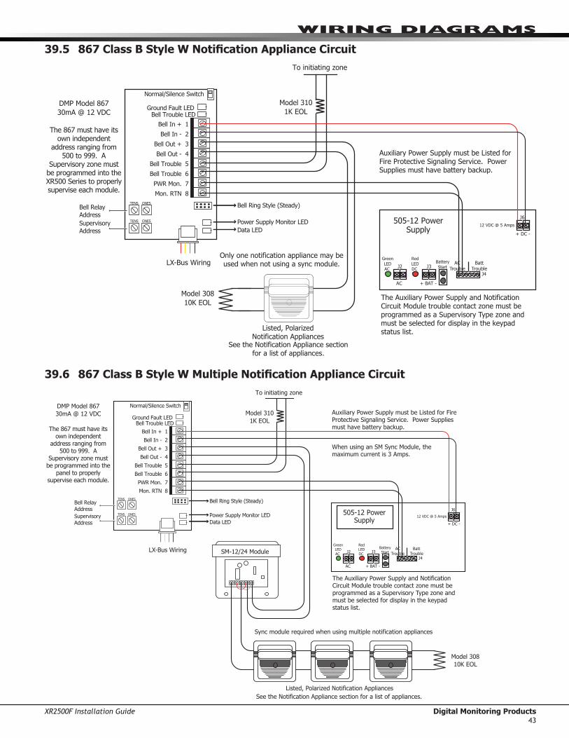
XR2500F Installation Guide Digital Monitoring Products43
WIRInG dIaGRaMs
39.5 867 Class B Style W Notification Appliance Circuit
Model 310
1K EOL
To initiating zone
Normal/Silence Switch
Ground Fault LEDBell Trouble LED
Bell In + 1
Bell In - 2
Bell Out + 3
Bell Out - 4
Bell Trouble 5
Bell Trouble 6
PWR Mon. 7
Mon. RTN 8
TENS ONES
TENS ONES
Bell Relay
Address
Supervisory
Address
Bell Ring Style (Steady)
Power Supply Monitor LED
Data LED
505-12 Power Supply
J6
+ DC -
AC Trouble
Batt Trouble
J4
J3J2
Green LED AC
AC + BAT -
Red LED DC
12 VDC @ 5 Amps
Battery Start
The Auxiliary Power Supply and Notification Circuit Module trouble contact zone must be programmed as a Supervisory Type zone and must be selected for display in the keypad status list.
Auxiliary Power Supply must be Listed for Fire Protective Signaling Service. Power Supplies must have battery backup.
LX-Bus Wiring
Model 308
10K EOL
Listed, Polarized Notification Appliances
DMP Model 867
30mA @ 12 VDC
The 867 must have its own independent
address ranging from 500 to 999. A
Supervisory zone must be programmed into the XR500 Series to properly supervise each module.
Only one notification appliance may be used when not using a sync module.
See the Notification Appliance section for a list of appliances.
39.6 867 Class B Style W Multiple Notification Appliance Circuit
Model 310
1K EOL
Normal/Silence Switch
Ground Fault LEDBell Trouble LED
Bell In + 1
Bell In - 2
Bell Out + 3
Bell Out - 4
Bell Trouble 5
Bell Trouble 6
PWR Mon. 7
Mon. RTN 8
TENS ONES
TENS ONES
Bell Relay
Address
Supervisory
Address
Bell Ring Style (Steady)
Power Supply Monitor LED
Data LED
505-12 Power Supply
J6
+ DC -
AC Trouble
Batt Trouble
J4
J3J2
Green LED AC
AC + BAT -
Red LED DC
12 VDC @ 5 Amps
Battery Start
The Auxiliary Power Supply and Notification Circuit Module trouble contact zone must be programmed as a Supervisory Type zone and must be selected for display in the keypad status list.
Auxiliary Power Supply must be Listed for Fire Protective Signaling Service. Power Supplies must have battery backup.
LX-Bus Wiring
Model 308
10K EOL
Listed, Polarized Notification Appliances
DMP Model 867
30mA @ 12 VDC
The 867 must have its own independent
address ranging from 500 to 999. A
Supervisory zone must be programmed into the
panel to properly supervise each module.
SM-12/24 Module
When using an SM Sync Module, the maximum current is 3 Amps.
See the Notification Appliance section for a list of appliances.
Sync module required when using multiple notification appliances
To initiating zone

Digital Monitoring Products XR2500F Installation Guide44
WIRInG dIaGRaMs
39.7 867 Class B Style W Multiple Notification Appliance Circuits
Model 310
1K EOL
To initiating zone
Normal/Silence Switch
Ground Fault LEDBell Trouble LED
Bell In + 1
Bell In - 2
Bell Out + 3
Bell Out - 4
Bell Trouble 5
Bell Trouble 6
PWR Mon. 7
Mon. RTN 8
TENS ONES
TENS ONES
Bell Relay
Address
Supervisory
Address
Bell Ring Style (Steady)
Power Supply Monitor LED
Data LED
505-12 Power Supply
J6
+ DC -
AC Trouble
Batt Trouble
J4
J3J2
Green LED AC
AC + BAT -
Red LED DC
12 VDC @ 5 Amps
Battery Start
The Auxiliary Power Supply and Notification Circuit Module trouble contact zone must be programmed as a Supervisory Type zone and must be selected for display in the keypad status list.
Auxiliary Power Supply must be Listed for Fire Protective Signaling Service. Power Supplies must have battery backup.
LX-Bus Wiring
DMP Model 867
30mA @ 12 VDC
The 867 must have its own independent
address ranging from 500 to 999. A
Supervisory zone must be programmed into the
panel to properly supervise each module.
MINUS 2MINUS 1+OUT 1 +IN 1 +IN 2-AUD+AUD +OUT 2
Model 308
10K EOL
Listed, Polarized Notification Appliances
DSM-12/24 Module
Model 308
10K EOL
See the Notification Appliance section for a list of appliances.
When using an DSM Sync Module, the maximum current is 3 Amps.
Sync module required when using multiple notification appliances

XR2500F Installation Guide Digital Monitoring Products45
WIRInG dIaGRaMs
39.8 Dual Style D Zone Module Installation
J6 Interface
Card Expansion Connector
XR2500F
Command Processor™
Panel
AC
1 2 3 4 5 6 7 8 10 11 12 13 14 15 16 17 18 199 20 21 22 23 24 25 26 27 28
+B BELLGND SMK GNDRED YEL GRN BLK Z1 Z2 Z3 Z4 Z5 Z6 Z7 Z8 Z9+ Z9– Z10+Z10–AC –B GND GND GNDGND
K6 K7
J3
J10
J22
Battery Start
J23
J21
RS-232
J8
J4Tamper
J16Reset
J11J2
J1
GND Fault A
GND Fault B
A1A1A2A2
Zone AGND
Zone B
B2B2
B1B1
Zone A
Zone B
Dual Style D Initiating ModuleDMP Model 869
25mA Standby, 75mA Alarm@ 12 VDC
Heat Detectors, manual pull stations, or any other listed shorting device. Unlimited number of units. S
S
Aux Power
S
S
S
S
S
S
Model 869
S = Supervised Circuit
SS S S
RLX
481 Z
one E
xpansi
on I
nte
rface
Card

Digital Monitoring Products XR2500F Installation Guide46
WIRInG dIaGRaMs
39.9 Remote Station Reversing Relay Connection
AC
1 2 3 4 5 6 7 8 10 11 12 13 14 15 16 17 18 199 20 21 22 23 24 25 26 27 28
+B BELLGND SMK GNDRED YEL GRN BLK Z1 Z2 Z3 Z4 Z5 Z6 Z7 Z8 Z9+ Z9– Z10+Z10–AC –B GND GND GNDGND
K6 K7
J3
J10
J22
Battery Start
J23
J21
RS-232
J4Tamper
J16Reset
Outp
uts
3-6J11
3 4 5 6
J2
J1
J6 Interface
Card Expansion Connector
J2 Output Header
All outputs must be located within the same room as the control panel.
Note: Output 1 must be programmed as a Fire Alarm Output and Output 2 must be programmed as a Fire Trouble Output. See Output Options section of the XR500 Series Programming Guide (LT-0679).
XR2500F
Command Processor™
Panel
Alternate Alarm
Combo Alarm
Auxiliary Power In
+ Signal Voltage In
+ To Remote Receiver
– To Remote Receiver
– Signal Voltage In
EARTH GROUND
GROUND
GROUND
Up to 60 hours of battery standby time can be supplied using multiple, sealed, Lead-Acid batteries.
See section titled Standby Battery Calculations.
To connect four batteries to the XR2500F Command Processor™ Panel, use three Model 318 Battery Harnesses.
Reversing Relay Module
Radionics Model D127
5mA Standby, 55mA Alarm
@12 VDC
Alternate Alarm
Combo Alarm
Auxiliary Power In
+ Signal Voltage In
+ To Remote Receiver
– To Remote Receiver
– Signal Voltage In
EARTH GROUND
GROUND
GROUND
Reversing Relay Module
Radionics Model D127
5mA Standby, 55mA Alarm
@12 VDC
To Telephone Line
To Telephone Line
S = Supervised Circuit
Intended for connection to a polarity reversal circuit of a remote station receiving unit having compatible ratings.
All modules must be installed in a listed enclosure connected by no more than 20 feet of conduit.
Fire Alarm Output 6 - White/Orange
Fire Trouble Output 5 - White/Yellow
S
SS
S
Model 431Output Harness
+ – + –
Bla
ckRed
+ – + –
Bla
ckRed
S
RLX
Out
1O
ut
2 NOCNCNOCNC
481 Z
one E
xpansi
on I
nte
rface
Card

XR2500F Installation Guide Digital Monitoring Products47
WIRInG dIaGRaMs
39.10 Second LX-Bus™ with Auxiliary Power Supply
AC
1 2 3 4 5 6 7 8 10 11 12 13 14 15 16 17 18 199 20 21 22 23 24 25 26 27 28
+B BELL GND SMK GNDRED YEL GRN BLK Z1 Z2 Z3 Z4 Z5 Z6 Z7 Z8 Z9+ Z9- Z10+ Z10-AC -B GND GND GNDGND
K6 K7
Output 1 Output 2
J3
Phone Line
J10
J22
LX-Bus
Battery Start
J23
J21
RS-232Power LED
J8
PROG
J4
Tamper
Out2 J11
3 4 5 6
J2
J1
Ethernet
XR2500F
Command
Processor™ Panel
A B C D
RLX
Red
Yellow
Green
Black
SRed
Yellow
Green
Black
SSSSSS
Red
Yellow
Green
Black
SRed
Yellow
Green
Black
Red
Yellow
Green
Black
SSDMP
505-12
716
N/O C N/C
SSSSS710
100 zones on LX-Bus 1, Numbered 500 to 599.
100 zones on LX-Bus 2, Numbered 600 to 699.
LX-Bus Expansion Cards:DMP Models 481, 462N, 462P, 463G, and 472 Interface Cards
Do not connect the red wire between the Interface Card and the first device.
Connect the red wire to Smoke Output (terminal 11).
S = 521LX or 5212LXT Addressable Smoke Detector
Refer to LT-0310 for more information about the 710/710F Bus Splitter/Repeater Module.
LX-Bus 1
LX-Bus 2
Program the 716 Output Expander Module as Sensor Reset Output.
J16Reset
E
481

Digital Monitoring Products XR2500F Installation Guide48
WIRInG dIaGRaMs
39.11 LX-Bus™ Module Connection
Model 716 Output
Expander Module
13m at 12 VDC
Model 717 Graphic
Annunciator
Module
10m at 12 VDC
To additional LX-Bus Modules
Red
Yellow
Green
Black
LX-Bus™ Wiring
Each LX-Bus Module must have its own independent address ranging from 00 to 99. A Supervisory zone must be programmed into the XR500 Series to properly supervise each module.
LX-Bus Expansion
Interface Card
DMP Models 481, 462N,
462P, 463G, or 472
S
S
S
S
S
S
S
S
S
S
SS
S = Supervised Circuit
Open Collector Annunciator Outputs
Rela
y 1
Rela
y 2
Rela
y 3
Relay 4
Optional LED wiring 50mA at 50 VDC resistive
Form C Contacts Typical
Normally ClosedCommonNormally Open
Optional LED wiring 50mA at 50 VDC resistive

XR2500F Installation Guide Digital Monitoring Products49
WIRInG dIaGRaMs
39.12 Model 860 Relay Module Connection
J6 Interface
Card Expansion Connector
XR2500F
Command Processor™
Panel
K3J2 Output Header
All outputs must be located within the same room as
the control panel.
AC
1 2 3 4 5 6 7 8 10 11 12 13 14 15 16 17 18 199 20 21 22 23 24 25 26 27 28
+B BELLGND SMK GNDRED YEL GRN BLK Z1 Z2 Z3 Z4 Z5 Z6 Z7 Z8 Z9+ Z9– Z10+Z10–AC –B GND GND GNDGND
K6 K7
J3
J10
J22
Battery Start
J23
J21
RS-232
J4Tamper
J16Reset
J11J2
J1
RLX
{{
{
{
+12 VDC
Relay 4
Relay 3
Relay 2
Relay 1 Common
J2
Model 860
Relay Module
Relay contact rating:1 Amp @ 30 VDC, resistive
4-wireHarnessAssembly
1234
REDYELGRNBLK
N/C
N/O
Red
481 Z
one E
xpansi
on I
nte
rface
Card
39.13 Powered Burglary Devices
XR2500F Series
Command Processor™
Panel
AC
1 2 3 4 5 6 7 8 10 11 12 13 14 15 16 17 18 199 20 21 22 23 24 25 26 27 28
+B BELLGND SMK GNDRED YEL GRN BLK Z1 Z2 Z3 Z4 Z5 Z6 Z7 Z8 Z9+ Z9– Z10+Z10–AC –B GND GND GNDGND
K6 K7
J3
J10
J22
Battery Start
J23
J21
RS-232
J8
J4Tamper
J16Reset
J11J2
J1
RLX
Green
Black
Red
Yellow
J14J12J10J7J5
TXD
J2
KYPD LX
TENS ONES
Z13+
Z13-
Z14+
Z14-
Z15+
Z15-
Z16+
Z16-
Z9+
Z9-
Z10+
Z10-
Z11+
Z11-
Z12+
Z12-
Z5+
Z5-
Z6+
Z6-
Z7+
Z7-
Z8+
Z8-
Z1+
Z1-
Z2+
Z2-
Z3+
Z3-
Z4+
Z4-BLK
GRN
YEL
RED
Gre
en
Bla
ck
Red
Yello
w
J3
12 VDC 1k EOL
Zone Expander
7060 Keypad
PIR or
Glassbreak
Zone Connection
+ –
505-12 Power
Supply
+ –
481 Z
one E
xpansi
on I
nte
rface
Card
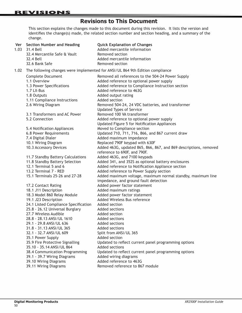
Digital Monitoring Products XR2500F Installation Guide50
RevIsIons
Revisions to This DocumentThissectionexplainsthechangesmadetothisdocumentduringthisrevision.Itliststheversionandidentifiesthechange(s)made,therelatedsectionnumberandsectionheading,andasummaryofthechange.
Ver Section Number and Heading Quick Explanation of Changes1.03 31.4Bell Addedmercantileinformation 32.4MercantileSafe&Vault Removedsection 32.4Bell Addedmercantileinformation 32.6BankSafe Removedsection
1.02 ThefollowingchangeswereimplementedforANSI/UL8649thEditioncompliance CompleteDocument Removedallreferencestothe504-24PowerSupply 1.1Overview Addedreferencetooptionalpowersupply 1.3PowerSpecifications AddedreferencetoComplianceInstructionsection 1.7LX-Bus Addedreferenceto463G 1.8Outputs Addedoutputrating 1.11ComplianceInstructions Addedsection 2.6WiringDiagram Removed504-24,24VDCbatteries,andtransformer
UpdatedTypesofService 3.1TransformersandACPower Removed100VAtransformer 5.2Connection Addedreferencetooptionalpowersupply
UpdatedFigure5forNotificationAppliances 5.4NotificationAppliances MovedtoCompliancesection 6.8PowerRequirements Updated710,711,716,866,and867currentdraw 7.4DigitalDialer Addedmaximumimpedance 10.1WiringDiagram Replaced790Fkeypadwith630F 10.3AccessoryDevices Added463G,updated865,866,867,and869descriptions,removed
referenceto690F,and790F. 11.7StandbyBatteryCalculations Added463G,and7100keypads 11.8StandbyBatterySelection Added341,and352Sasoptionalbatteryenclosures 12.1Terminal5and6 AddedreferencetoNotificationAppliancesection 13.2Terminal7-RED AddedreferencetoPowerSupplysection 15.1Terminals25-26and27-28 Addedmaximumvoltage,maximumnormalstandby,maximumline
impedance,andgroundfaultdetection 17.2ContactRating Addedpowerfactorstatement 18.1J11Description Addedmaximumratings 18.3Model860RelayModule Addedpowerfactorstatement 19.1J23Description AddedWirelessBusreference 24.1ListedComplianceSpecification Addedsection 25.8-26.12UniversalBurglary Addedsections 27.7WirelessAudible Addedsection 28.8-28.13ANSI/UL1610 Addedsections 29.1-29.8ANSI/UL636 Addedsections 31.8-31.13ANSI/UL365 Addedsections 32.1-32.7ANSI/UL609 SplitfromANSI/UL365 35.1PowerSupply Addedsection 35.9FireProtectiveSignalling Updatedtoreflectcurrentpanelprogrammingoptions 35.10-35.14ANSI/UL864 Addedsections 38.4CommunicationProgramming Updatedtoreflectcurrentpanelprogrammingoptions 39.1-39.7WiringDiagrams Addedwiringdiagrams 39.10WiringDiagrams Addedreferenceto463G 39.11WiringDiagrams Removedreferenceto867module

XR2500F Installation Guide Digital Monitoring Products51
This page intentionally left blank

LT-07591.03©2009DigitalMon
itoringProd
ucts,Inc.
800-641-4282
www.dmp.com
MadeintheUSA
INTRUSION•FIRE•ACCESS•NETWORKS
2500NorthPartnershipBoulevard
Springfield,Missouri65803-8877
9043
OPERATING INSTRUCTIONS MODEL XR2500F PANELS
NORMAL STANDBY CONDITIONWhenthesystemisinthenormalstandbycondition,thekeypadshowseitherthetimeofdayorablankdisplay.
ALARM CONDITIONWhenthesystemisinanalarmcondition,thekeypaddisplayshowstheviolatedzonename(s)followedbyanalarm display.
ALARM SILENCETosilencethealarmwhilethebellorsirenissounding,enteryourcodenumberandpresstheCOMMANDkey.This silences the alarm but does not cancel any alarm reports to the central station.
RESETTING DETECTORSToresetasmokeorotherdetector,entertheUserMenubypressingtheCOMMANDkeyuntilMENU? NO YES appears in the display. Press the top row key under YES. The display shows ENTER CODE: -.EnteryourcodenumberandpressCOMMAND.ThekeypaddisplaynowshowsALARM SILENCE? ifyourcodeallows.PresstheCOMMANDkeyuntilSENSOR RESET? appears in the display. Press any top row key.
TROUBLE CONDITIONWhenadeviceisinatroublecondition,thekeypadtonesanddisplaysthezoneordevicenamefollowedbyTRBL. Press any top row key to silence.
SYSTEM TESTINGYoushouldtestthesecuritysystemweeklytoensureproperoperation.Youcandothisthrougha functionintheUserMenu.AfterenteringtheUserMenu,presstheCOMMANDkeyuntilSYSTEM TEST? displays.PresstheleftmosttoprowSelectkey.Thesystembell,battery,andcommunicationtothecentralstationreceiversystemisthen tested.
ALARM SERVICEIfserviceisrequiredforthissystem,pleasecontact:
Company _____________________________________________
Address ______________________________________________
Telephone ____________________________________________
Mounting InstructionsAttachtheaboveoperatinginstructionstothefront,orframedandlocatedadjacentto,thepanelorakeypadwithan alphanumeric display.
Listings and ApprovalsCaliforniaStateFireMarshal(CSFM)FCC Part 15FCCPart68RegistrationIDCCKAL00BXR500NewYorkCity(MEA)UnderwritersLaboratories(UL)Listed CommercialandResidentialFire,Burglar,Holdup,andAccessProtectedPremiseUnit
ANSI/UL294 AccessControlSystemUnits ANSI/UL365 PoliceConnectedBurglar ANSI/UL609 LocalBurglar ANSI/UL636 HoldupAlarmUnitsSystemsAccessory ANSI/UL1023 HouseholdBurglar ANSI/UL1076 ProprietaryBurglar ANSI/UL1610 CentralStationBurglar ANSI/UL1635 DigitalBurglar ANSI/UL985 HouseholdFireWarning ANSI/UL864 FireProtectiveSignaling9thEdition
ULStandardLineSecurityULEncryptedLineSecurity