dmm technology corp. dyn ac servo drive modbus rtu ... · please review the manual “modbus over...
TRANSCRIPT

DMM Technology Corp. DYN AC Servo Drive Modbus RTU Specification [DYNMB1-BL1645-10A ] Document Version 1.0A Published Sept 17, 2017
March 02, 2017 Version 1.0
DYN AC Servo Drive Modbus RTU Specification
2
1. Overview
The DYN2 and DYN4 servo drive supports Modbus RTU communication protocol over RS485 through the servo drive’s JP2 PC Interface connector. The following servo drive mode numbers supports this Modbus RTU protocol.
DYN2-T1B6S-00
DYN2-TLB6S-00
DYN4-L01B2-00
DYN4-H01B2-00
DYN4-T01B2-00
64 DYN servo drive nodes can be connected on a single network. The following communication formats and baud rates are supported:
Baud Rate Protocol
4800
9600
19200
38400 (Default)
57600
115200 * Custom baud rates up to 340.8k bps can be requested
8-bit data, 1 start bit, no parity, two stop bits (Default)
8-bit data, 1 start bit, odd parity, one stop bit
8-bit data, 1 start bit, even parity, one stop bit
Please review the manual “MODBUS over serial line specification and implementation guide V1.02” from www.modbus.org for detailed communication and connection specifications.
2. Hardware Interface
Connector
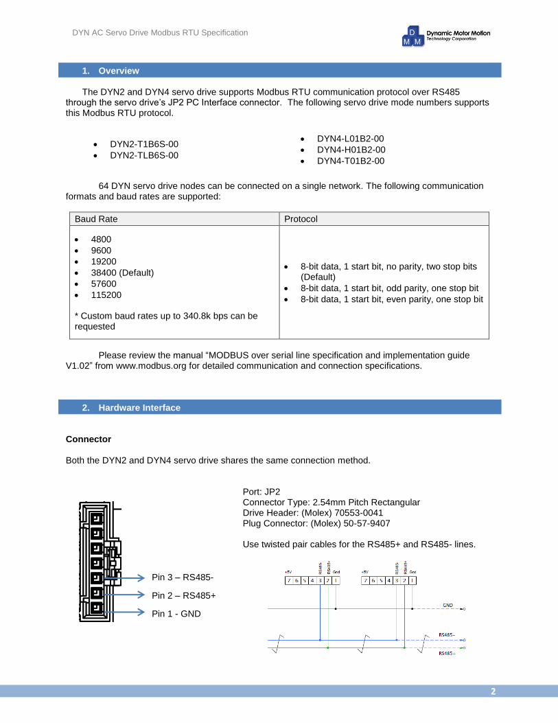
Both the DYN2 and DYN4 servo drive shares the same connection method.
Port: JP2 Connector Type: 2.54mm Pitch Rectangular Drive Header: (Molex) 70553-0041 Plug Connector: (Molex) 50-57-9407 Use twisted pair cables for the RS485+ and RS485- lines.
Pin 1 - GND
Pin 2 – RS485+
Pin 3 – RS485-
DYN AC Servo Drive Modbus RTU Specification
3
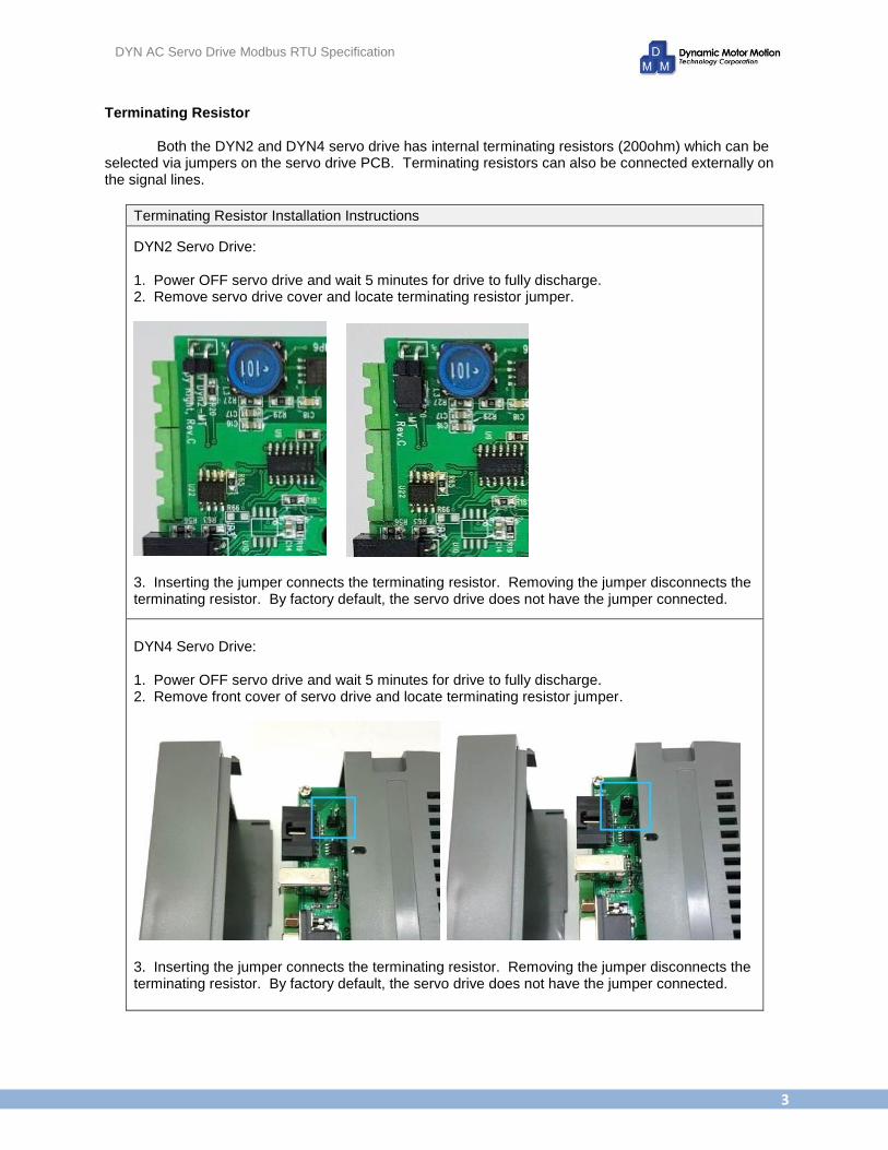
Terminating Resistor Both the DYN2 and DYN4 servo drive has internal terminating resistors (200ohm) which can be selected via jumpers on the servo drive PCB. Terminating resistors can also be connected externally on the signal lines.
Terminating Resistor Installation Instructions
DYN2 Servo Drive: 1. Power OFF servo drive and wait 5 minutes for drive to fully discharge. 2. Remove servo drive cover and locate terminating resistor jumper.
3. Inserting the jumper connects the terminating resistor. Removing the jumper disconnects the terminating resistor. By factory default, the servo drive does not have the jumper connected.
DYN4 Servo Drive: 1. Power OFF servo drive and wait 5 minutes for drive to fully discharge. 2. Remove front cover of servo drive and locate terminating resistor jumper.
3. Inserting the jumper connects the terminating resistor. Removing the jumper disconnects the terminating resistor. By factory default, the servo drive does not have the jumper connected.

DYN AC Servo Drive Modbus RTU Specification
4
JP2 RJ45 Splitter The RJ45 splitter can also be used to network multiple drives using standard RH45 modular cables and connectors. The splitter connects into either DYN2 or DYN4 JP2 ports and splits the RS485+ and RS485- signals between two RJ45 ports. The RJ45 splitter is sold separately. The pin out follows the Modbus mechanical interface standard for 2-Wire Modbus. Part# CNJP2-RJ45SP-2 Circuit Diagram:
DYN2 Servo Drive Application:
DYN4 Servo Drive Application:
DYN AC Servo Drive Modbus RTU Specification
5
3. Servo Drive Setting
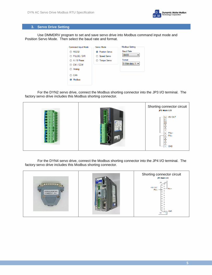
Use DMMDRV program to set and save servo drive into Modbus command input mode and Position Servo Mode. Then select the baud rate and format.
For the DYN2 servo drive, connect the Modbus shorting connector into the JP3 I/O terminal. The factory servo drive includes this Modbus shorting connector.
Shorting connector circuit
For the DYN4 servo drive, connect the Modbus shorting connector into the JP4 I/O terminal. The factory servo drive includes this Modbus shorting connector.
Shorting connector circuit
DYN AC Servo Drive Modbus RTU Specification
6
IMPORTANT
Once the servo drive is saved into Modbus command input mode and the shorting connector is
connected, power OFF the drive, wait 60-seconds and power ON again to activate the Modbus mode. When the drive is in Modbus mode, the RS232 communication is stopped and the drive will not communicate with the DMMDRV program. By disconnecting the shorting connector and cycling power, the servo drive will go into RS232 mode and can be accessed via DMMDRV program. The servo drive is only in Modbus mode if the command input mode is selected as “Modbus” and the Modbus shorting connector is connected to the servo drive. Modbus mode becomes effective after power cycle. Setup Procedure
Setting into Modbus mode
1. Power ON servo drive.
2. Set Command Input Mode into “Modbus”.
3. Set Servo Mode into “Position Servo”.
4. Select Baud Rate and Format according to network requirement.
5. Press “Save All” to save above settings. At this point, the servo drive is internally still in RS232
mode. User can continue using DMMDRV for testing and tuning.
6. Power OFF servo drive. Wait 60 seconds.
7. Connect Modbus Shorting Connector to servo drive.
8. Power servo drive ON. Now, the servo drive is in Modbus mode and ready for Modbus operation.
Will not communicate via RS232 and DMMDRV.
Switching back to RS232 mode
9. Power servo drive OFF. Wait 60 seconds.
10. Disconnect Modbus Shorting Connector.
11. Power servo drive ON. Servo drive is back in RS232 mode and able to communicate with
DMMDRV.
DYN AC Servo Drive Modbus RTU Specification
7
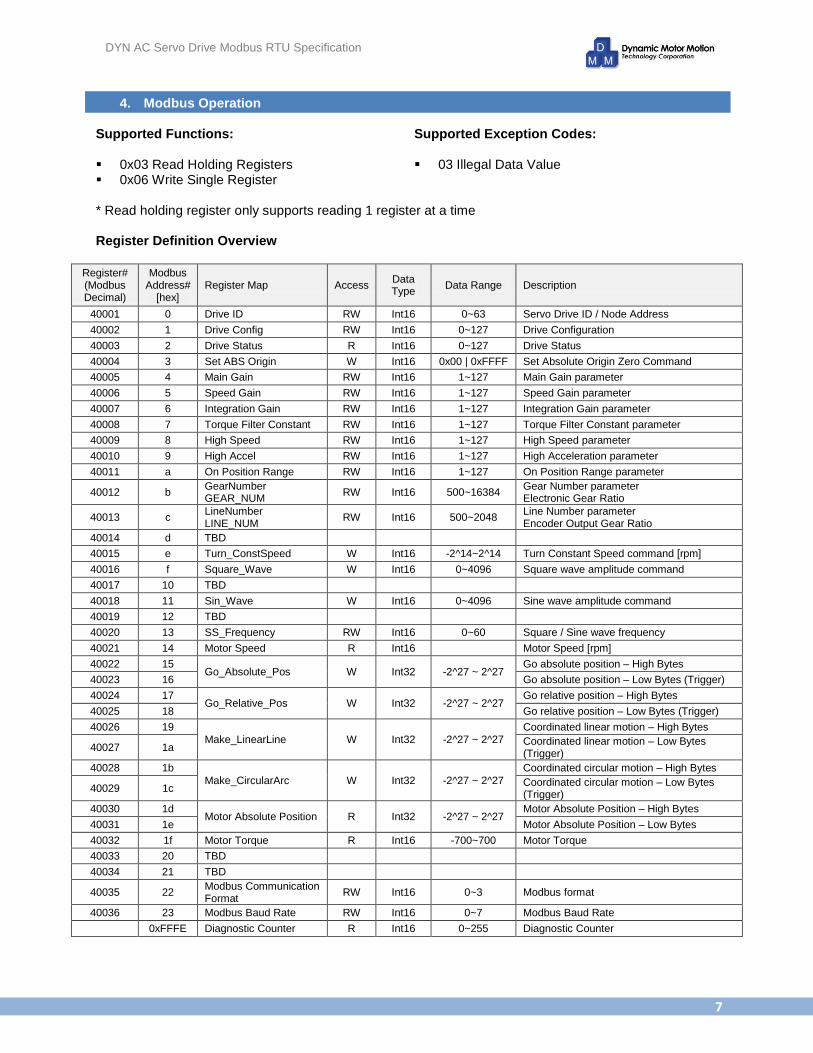
4. Modbus Operation Supported Functions: 0x03 Read Holding Registers 0x06 Write Single Register
Supported Exception Codes: 03 Illegal Data Value
* Read holding register only supports reading 1 register at a time Register Definition Overview
Register# (Modbus Decimal)
Modbus Address#
[hex] Register Map Access
Data Type
Data Range Description
40001 0 Drive ID RW Int16 0~63 Servo Drive ID / Node Address
40002 1 Drive Config RW Int16 0~127 Drive Configuration
40003 2 Drive Status R Int16 0~127 Drive Status
40004 3 Set ABS Origin W Int16 0x00 | 0xFFFF Set Absolute Origin Zero Command
40005 4 Main Gain RW Int16 1~127 Main Gain parameter
40006 5 Speed Gain RW Int16 1~127 Speed Gain parameter
40007 6 Integration Gain RW Int16 1~127 Integration Gain parameter
40008 7 Torque Filter Constant RW Int16 1~127 Torque Filter Constant parameter
40009 8 High Speed RW Int16 1~127 High Speed parameter
40010 9 High Accel RW Int16 1~127 High Acceleration parameter
40011 a On Position Range RW Int16 1~127 On Position Range parameter
40012 b GearNumber GEAR_NUM
RW Int16 500~16384 Gear Number parameter Electronic Gear Ratio
40013 c LineNumber LINE_NUM
RW Int16 500~2048 Line Number parameter Encoder Output Gear Ratio
40014 d TBD
40015 e Turn_ConstSpeed W Int16 -2^14~2^14 Turn Constant Speed command [rpm]
40016 f Square_Wave W Int16 0~4096 Square wave amplitude command
40017 10 TBD
40018 11 Sin_Wave W Int16 0~4096 Sine wave amplitude command
40019 12 TBD
40020 13 SS_Frequency RW Int16 0~60 Square / Sine wave frequency
40021 14 Motor Speed R Int16
Motor Speed [rpm]
40022 15 Go_Absolute_Pos W Int32 -2^27 ~ 2^27
Go absolute position – High Bytes
40023 16 Go absolute position – Low Bytes (Trigger)
40024 17 Go_Relative_Pos W Int32 -2^27 ~ 2^27
Go relative position – High Bytes
40025 18 Go relative position – Low Bytes (Trigger)
40026 19 Make_LinearLine W Int32 -2^27 ~ 2^27
Coordinated linear motion – High Bytes
40027 1a Coordinated linear motion – Low Bytes (Trigger)
40028 1b
Make_CircularArc W Int32 -2^27 ~ 2^27
Coordinated circular motion – High Bytes
40029 1c Coordinated circular motion – Low Bytes (Trigger)
40030 1d Motor Absolute Position R Int32 -2^27 ~ 2^27
Motor Absolute Position – High Bytes
40031 1e Motor Absolute Position – Low Bytes
40032 1f Motor Torque R Int16 -700~700 Motor Torque
40033 20 TBD
40034 21 TBD
40035 22 Modbus Communication Format
RW Int16 0~3 Modbus format
40036 23 Modbus Baud Rate RW Int16 0~7 Modbus Baud Rate
0xFFFE Diagnostic Counter R Int16 0~255 Diagnostic Counter
DYN AC Servo Drive Modbus RTU Specification
8
Register Definition Details
Register# (Modbus Decimal)
Modbus Address# [hex]
Register Map Access Data Type Data Range
40001 0 Drive ID RW Int16 0~63
Details
Read/Write the servo drive ID, which corresponds to its Modbus node address. The DYN servo drive accepts addresses from 0 to 63, allowing up to 64 drive nodes to be connected on one bus. ID=0 is for broadcasting and the servo drive does not sent response or error messages.
Register# (Modbus Decimal)
Modbus Address# [hex]
Register Map Access Data Type Data Range
40002 1 Drive Config RW Int16 0~127
Details
Read/Write the servo drive Configuration. Only the lower byte is used. Drive Configuration = b7 b6 b5 b4 b3 b2 b1 b0
b1 b0 =
0 = 1 = 2 = 3 =
Command Input Mode RS232 mode CW,CCW mode Pulse/Direction mode Analog mode
b2 =
0 = 1 =
Relative or Absolute Mode (Encoder Mode) Works as relative mode. Operates as incremental encoder. Works as absolute mode. At power up, motors moves to absolute zero or stored zero position. See Set ABS Origin command for details.
b4 b3 =
0 = 1 = 2 =
Servo Mode Position Servo Mode (default for Modbus) Speed Servo Mode Torque Servo Mode
b5 = 0 = 1 =
Servo Enable/Disable Servo Enabled Servo Disabled (Motor Free)
b7 b6 = Unimplemented

DYN AC Servo Drive Modbus RTU Specification
9
Register# (Modbus Decimal)
Modbus Address# [hex]
Register Map Access Data Type Data Range
40003 2 Drive Status R Int16 0~127
Details
Reads the servo drive Status. Only the lower byte is used. Drive Status = b7 b6 b5 b4 b3 b2 b1 b0
b0 = 0 = 1 =
On position. |Pset - Pmotor| < = OnpositionRange Off Position / motor busy. |Pset - Pmotor| > OnPositionRange
b1 = 0 = 1 =
Servo Enabled Servo Disabled / Motor Free
b4 b3 b2 = 0 = 1 = 2 = 3 = 4 =
No Alarm Motor lost phase alarm, |Pset - Pmotor|>8192(steps), 180(deg) Over current alarm Overheat alarm / Overpower alarm Error for CRC code check, refuse to accept current command
b5 = 0 = 1 =
Built in S-curve, linear, circular motion completed; waiting for next motion Built in S-curve, linear, circular motion is busy on current motion
b7 b6 = Unimplemented
Register# (Modbus Decimal)
Modbus Address# [hex]
Register Map Access Data Type Data Range
40004 3 Set ABS Origin W Int16 0x00 | 0xFFFF
Details
Setting this address to 0xFFFF sets the current motor position as the absolute zero position. When the drive is set to operate in Absolute Mode (Configuration&0x04=1), when the drive powers ON, the motor moves to the absolute zero position, then starts accepting command.
Register# (Modbus Decimal)
Modbus Address# [hex]
Register Map Access Data Type Data Range
40005 4 Main Gain RW Int16 1~127
40006 5 Speed Gain RW Int16 1~127
40007 6 Integration Gain RW Int16 1~127
40008 7 Torque Filter Constant
RW Int16 1~127
Details
These registers are used to set/read the corresponding drive parameter. Since the max allowed value is 127, only the lower byte is used. Saving a 0 or any value higher than 127 into these registers returns 03 exception code.
DYN AC Servo Drive Modbus RTU Specification
10
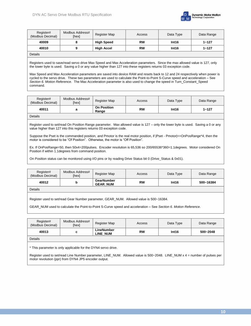
Register# (Modbus Decimal)
Modbus Address# [hex]
Register Map Access Data Type Data Range
40009 8 High Speed RW Int16 1~127
40010 9 High Accel RW Int16 1~127
Details
Registers used to save/read servo drive Max Speed and Max Acceleration parameters. Since the max allowed value is 127, only the lower byte is used. Saving a 0 or any value higher than 127 into these registers returns 03 exception code. Max Speed and Max Acceleration parameters are saved into device RAM and resets back to 12 and 24 respectively when power is cycled to the servo drive. These two parameters are used to calculate the Point-to-Point S-Curve speed and acceleration – See Section 6. Motion Reference. The Max Acceleration parameter is also used to change the speed in Turn_Constant_Speed command.
Register# (Modbus Decimal)
Modbus Address# [hex]
Register Map Access Data Type Data Range
40011 a On Position Range
RW Int16 1~127
Details
Register used to set/read On Position Range parameter. Max allowed value is 127 – only the lower byte is used. Saving a 0 or any value higher than 127 into this registers returns 03 exception code. Suppose the Pset is the commanded position, and Pmotor is the real motor position, if |Pset - Pmotor|<=OnPosRange*4, then the motor is considered to be “Of Position”. Otherwise, the motor is “Off Position”. Ex. If OnPosRange=50, then 50x4=200pulses. Encoder resolution is 65,536 so 200/65536*360=1.1degrees. Motor considered On Position if within 1.1degrees from command position. On Position status can be monitored using I/O pins or by reading Drive Status bit 0 (Drive_Status & 0x01).
Register# (Modbus Decimal)
Modbus Address# [hex]
Register Map Access Data Type Data Range
40012 b GearNumber GEAR_NUM
RW Int16 500~16384
Details
Register used to set/read Gear Number parameter, GEAR_NUM. Allowed value is 500~16384. GEAR_NUM used to calculate the Point-to-Point S-Curve speed and acceleration – See Section 6. Motion Reference.
Register# (Modbus Decimal)
Modbus Address# [hex]
Register Map Access Data Type Data Range
40013 c LineNumber LINE_NUM
RW Int16 500~2048
Details
* This parameter is only applicable for the DYN4 servo drive. Register used to set/read Line Number parameter, LINE_NUM. Allowed value is 500~2048. LINE_NUM x 4 = number of pulses per motor revolution (ppr) from DYN4 JP5 encoder output.
DYN AC Servo Drive Modbus RTU Specification
11
Register# (Modbus Decimal)
Modbus Address# [hex]
Register Map Access Data Type Data Range
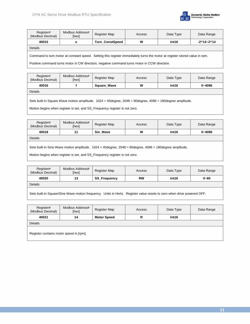
40015 e Turn_ConstSpeed W Int16 -2^14~2^14
Details
Command to turn motor at constant speed. Setting this register immediately turns the motor at register stored value in rpm. Positive command turns motor in CW direction, negative command turns motor in CCW direction.
Register# (Modbus Decimal)
Modbus Address# [hex]
Register Map Access Data Type Data Range
40016 f Square_Wave W Int16 0~4096
Details
Sets built-in Square Wave motion amplitude. 1024 = 45degree, 2048 = 90degree, 4096 = 180degree amplitude. Motion begins when register is set, and SS_Frequency register is not zero.
Register# (Modbus Decimal)
Modbus Address# [hex]
Register Map Access Data Type Data Range
40018 11 Sin_Wave W Int16 0~4096
Details
Sets built-in Sine Wave motion amplitude. 1024 = 45degree, 2048 = 90degree, 4096 = 180degree amplitude. Motion begins when register is set, and SS_Frequency register is not zero.
Register# (Modbus Decimal)
Modbus Address# [hex]
Register Map Access Data Type Data Range
40020 13 SS_Frequency RW Int16 0~60
Details
Sets built-in Square/Sine Wave motion frequency. Units in Hertz. Register value resets to zero when drive powered OFF.
Register# (Modbus Decimal)
Modbus Address# [hex]
Register Map Access Data Type Data Range
40021 14 Motor Speed R Int16
Details
Register contains motor speed in [rpm].
DYN AC Servo Drive Modbus RTU Specification
12
Register# (Modbus Decimal)
Modbus Address# [hex]
Register Map Access Data Type Data Range
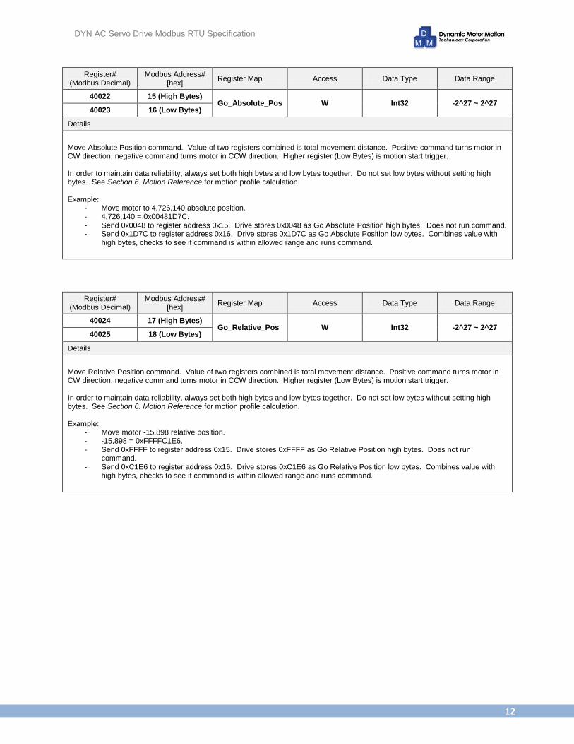
40022 15 (High Bytes) Go_Absolute_Pos W Int32 -2^27 ~ 2^27
40023 16 (Low Bytes)
Details
Move Absolute Position command. Value of two registers combined is total movement distance. Positive command turns motor in CW direction, negative command turns motor in CCW direction. Higher register (Low Bytes) is motion start trigger. In order to maintain data reliability, always set both high bytes and low bytes together. Do not set low bytes without setting high bytes. See Section 6. Motion Reference for motion profile calculation. Example:
- Move motor to 4,726,140 absolute position. - 4,726,140 = 0x00481D7C. - Send 0x0048 to register address 0x15. Drive stores 0x0048 as Go Absolute Position high bytes. Does not run command. - Send 0x1D7C to register address 0x16. Drive stores 0x1D7C as Go Absolute Position low bytes. Combines value with
high bytes, checks to see if command is within allowed range and runs command.
Register# (Modbus Decimal)
Modbus Address# [hex]
Register Map Access Data Type Data Range
40024 17 (High Bytes) Go_Relative_Pos W Int32 -2^27 ~ 2^27
40025 18 (Low Bytes)
Details
Move Relative Position command. Value of two registers combined is total movement distance. Positive command turns motor in CW direction, negative command turns motor in CCW direction. Higher register (Low Bytes) is motion start trigger. In order to maintain data reliability, always set both high bytes and low bytes together. Do not set low bytes without setting high bytes. See Section 6. Motion Reference for motion profile calculation. Example:
- Move motor -15,898 relative position. - -15,898 = 0xFFFFC1E6. - Send 0xFFFF to register address 0x15. Drive stores 0xFFFF as Go Relative Position high bytes. Does not run
command. - Send 0xC1E6 to register address 0x16. Drive stores 0xC1E6 as Go Relative Position low bytes. Combines value with
high bytes, checks to see if command is within allowed range and runs command.

DYN AC Servo Drive Modbus RTU Specification
13
Register# (Modbus Decimal)
Modbus Address# [hex]
Register Map Access Data Type Data Range
40026 19 (High Bytes) Make_LinearLine W Int32 -2^27 ~ 2^27
40027 1a (Low Bytes)
Details
See Section 7. Coordinated Linear Motion Reference.
Register# (Modbus Decimal)
Modbus Address# [hex]
Register Map Access Data Type Data Range
40028 1b (High Bytes) Make_CircularArc W Int32 -2^27 ~ 2^27
40029 1c (Low Bytes)
Details
See Section 8. Coordinated Circular Motion Reference.
Register# (Modbus Decimal)
Modbus Address# [hex]
Register Map Access Data Type Data Range
40030 1d (High Bytes) Motor Absolute Position
R Int32 -2^27 ~ 2^27 40031 1e (Low Bytes)
Details
These registers contain the absolute position of the motor. Make sure to always read the high bytes (0x1d) first, then the low bytes (0x1e). Read low bytes after high bytes as soon as possible to maintain best position reference. The absolute position is the stored position when the high bytes are read. Timing / Position Synchronization Example:
Time [ms] Motor Position [pts] Operation
0 69514
25 75201 0x1d register read command sent. Servo drive stores current position 75201 = 0x000125C1 and returns high bytes 0x0001
50 85218 0x1e register read command sent. Servo drive returns stored position low bytes 0x25C1
75 98521
…
125 129921 0x1d register read command sent. Servo drive stores current position 129921 = 0x0001FB81 and returns high bytes 0x0001
150 148759 0x1e register read command sent. Servo drive returns stored position low bytes 0xFB81
175 160258
DYN AC Servo Drive Modbus RTU Specification
14
Register# (Modbus Decimal)
Modbus Address# [hex]
Register Map Access Data Type Data Range
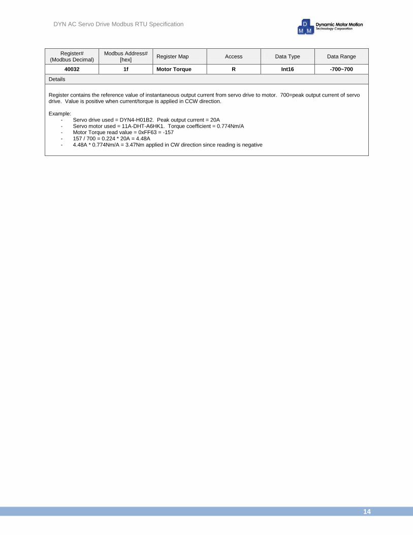
40032 1f Motor Torque R Int16 -700~700
Details
Register contains the reference value of instantaneous output current from servo drive to motor. 700=peak output current of servo drive. Value is positive when current/torque is applied in CCW direction. Example:
- Servo drive used = DYN4-H01B2. Peak output current = 20A - Servo motor used = 11A-DHT-A6HK1. Torque coefficient = 0.774Nm/A - Motor Torque read value = 0xFF63 = -157 - 157 / 700 = 0.224 * 20A = 4.48A - 4.48A * 0.774Nm/A = 3.47Nm applied in CW direction since reading is negative
DYN AC Servo Drive Modbus RTU Specification
15
Register# (Modbus Decimal)
Modbus Address# [hex]
Register Map Access Data Type Data Range
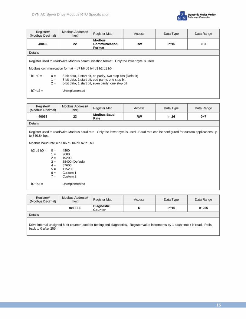
40035 22 Modbus Communication Format
RW Int16 0~3
Details
Register used to read/write Modbus communication format. Only the lower byte is used. Modbus communication format = b7 b6 b5 b4 b3 b2 b1 b0
b1 b0 = 0 = 1 = 2 =
8-bit data, 1 start bit, no parity, two stop bits (Default) 8-bit data, 1 start bit, odd parity, one stop bit 8-bit data, 1 start bit, even parity, one stop bit
b7~b2 = Unimplemented
Register# (Modbus Decimal)
Modbus Address# [hex]
Register Map Access Data Type Data Range
40036 23 Modbus Baud Rate
RW Int16 0~7
Details
Register used to read/write Modbus baud rate. Only the lower byte is used. Baud rate can be configured for custom applications up to 340.8k bps. Modbus baud rate = b7 b6 b5 b4 b3 b2 b1 b0
b2 b1 b0 = 0 = 1 = 2 = 3 = 4 = 5 = 6 = 7 =
4800 9600 19200 38400 (Default) 57600 115200 Custom 1 Custom 2
b7~b3 = Unimplemented
Register# (Modbus Decimal)
Modbus Address# [hex]
Register Map Access Data Type Data Range
0xFFFE Diagnostic Counter
R Int16 0~255
Details
Drive internal unsigned 8-bit counter used for testing and diagnostics. Register value increments by 1 each time it is read. Rolls back to 0 after 255.
DYN AC Servo Drive Modbus RTU Specification
16
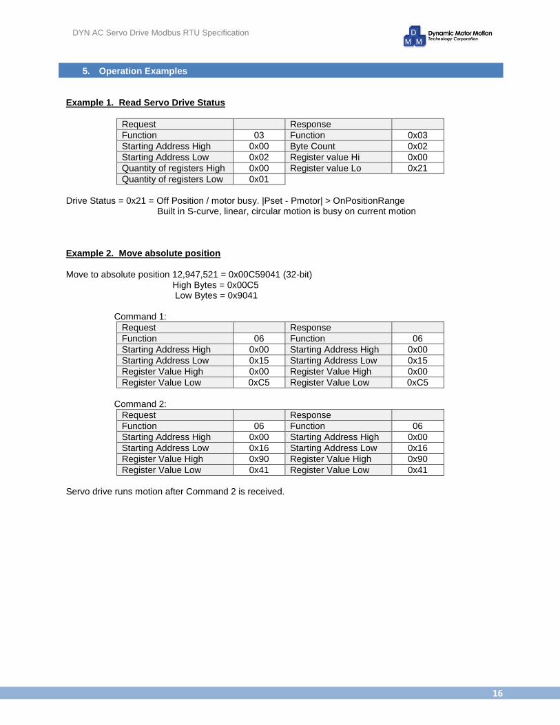
5. Operation Examples Example 1. Read Servo Drive Status
Request Response
Function 03 Function 0x03
Starting Address High 0x00 Byte Count 0x02
Starting Address Low 0x02 Register value Hi 0x00
Quantity of registers High 0x00 Register value Lo 0x21
Quantity of registers Low 0x01
Drive Status = 0x21 = Off Position / motor busy. |Pset - Pmotor| > OnPositionRange
Built in S-curve, linear, circular motion is busy on current motion Example 2. Move absolute position Move to absolute position 12,947,521 = 0x00C59041 (32-bit)
High Bytes = 0x00C5 Low Bytes = 0x9041
Command 1:
Request Response
Function 06 Function 06
Starting Address High 0x00 Starting Address High 0x00
Starting Address Low 0x15 Starting Address Low 0x15
Register Value High 0x00 Register Value High 0x00
Register Value Low 0xC5 Register Value Low 0xC5
Command 2:
Request Response
Function 06 Function 06
Starting Address High 0x00 Starting Address High 0x00
Starting Address Low 0x16 Starting Address Low 0x16
Register Value High 0x90 Register Value High 0x90
Register Value Low 0x41 Register Value Low 0x41
Servo drive runs motion after Command 2 is received.

DYN AC Servo Drive Modbus RTU Specification
17
Example 3. Read absolute position Command 1:
Request Response
Function 03 Function 0x03
Starting Address High 0x00 Byte Count 0x02
Starting Address Low 0x1d Register value Hi 0xFF
Quantity of registers High 0x00 Register value Lo 0x23
Quantity of registers Low 0x01
Command 2:
Request Response
Function 03 Function 0x03
Starting Address High 0x00 Byte Count 0x02
Starting Address Low 0x1e Register value Hi 0x11
Quantity of registers High 0x00 Register value Lo 0x8B
Quantity of registers Low 0x01
Register 1d = Absolute Position High bytes = 0xFF23 = INT16 ABS_Pos16_H Register 1e = Absolute Position Low bytes = 0x118B = INT16 ABS_Pos16_L INT32 ABS_Pos32 = ABS_Pos16_H & 0x0000FFFF; ABS_Pos32<<=16; ABS_Pos32 = ABS_Pos32 | ABS_Pos16_L; // ABS_Pos_32 = 32-bit absolute motor position * Note: For client/master devices that do not allow 32-bit data bit manipulation, copy the two 16-bit ABS_Pos16_H and ABS_Pos16_L data into two separate 32-bit Integer data types. The multiply the data containing ABS_Pos16_H by 65536 (shift left by 16) and add data containing ABS_Pos16_L. Example without 32-bit data bit-manipulation: INT32 ABS_Pos32_H, ABS_Pos32_L; ABS_Pos32_H = ABS_Pos16_H & 0x0000FFFF; ABS_Pos32_L = ABS_Pos16_L & 0x0000FFFF; ABS_Pos32 = ABS_Pos32_H*65536 + ABS_Pos32_L; // ABS_Pos_32 = 32-bit absolute motor position Example 4. Move constant speed Target motor speed = 4520rpm Target motor direction = CCW Command data = -4520 = 0xEE58
Request Response
Function 06 Function 06
Starting Address High 0x00 Starting Address High 0x00
Starting Address Low 0x0e Starting Address Low 0x0e
Register Value High 0xEE Register Value High 0xEE
Register Value Low 0x58 Register Value Low 0x58
Servo drive rotates motor at 4520rpm in CCW direction as soon as command received.

DYN AC Servo Drive Modbus RTU Specification
18
Example 5. 3-Axis Coordinated Linear Motion
X axis drive ID = 0 Y axis drive ID = 1 Z axis drive ID = 2 Set all 3 axis GEAR_NUM to 4096
Starting Coordinate = (547,201,1498) Target Coordinate = (1058,-5180,84750) Travel Distance = (511,-5381,83252) Travel Distance (32bit) = (0x000001FF,0xFFFFEAFB,0x00014534) Target Feed Rate = 300rpm – FeedRate = 300/1.526 = 196 = 0xC5
Command 1:
Request
Function 06
Starting Address High 0x00
Starting Address Low 0x19
Register Value High 0x00
Register Value Low 0x00
Command 2:
Request
Function 06
Starting Address High 0x00
Starting Address Low 0x1a
Register Value High 0x01
Register Value Low 0xFF
Command 3:
Request
Function 06
Starting Address High 0x00
Starting Address Low 0x19
Register Value High 0xFF
Register Value Low 0xFF
Command 4:
Request
Function 06
Starting Address High 0x00
Starting Address Low 0x1a
Register Value High 0xEA
Register Value Low 0xFB
Command 5:
Request
Function 06
Starting Address High 0x00
Starting Address Low 0x19
Register Value High 0x00
Register Value Low 0x01
Command 6:
Request
Function 06
Starting Address High 0x00
Starting Address Low 0x1a
Register Value High 0x45
Register Value Low 0x34
Command 7:
Request
Function 06
Starting Address High 0x00
Starting Address Low 0x19
Register Value High 0x00
Register Value Low 0x00
Command 8:
Request
Function 06
Starting Address High 0x00
Starting Address Low 0x1a
Register Value High 0x00
Register Value Low 0xC5
All 3 servo drive axis begins interpolated linear motion after 8th command received.
DYN AC Servo Drive Modbus RTU Specification
19
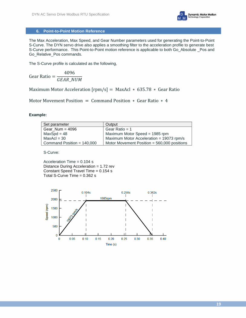
6. Point-to-Point Motion Reference The Max Acceleration, Max Speed, and Gear Number parameters used for generating the Point-to-Point S-Curve. The DYN servo drive also applies a smoothing filter to the acceleration profile to generate best S-Curve performance. This Point-to-Point motion reference is applicable to both Go_Absolute _Pos and Go_Relative_Pos commands. The S-Curve profile is calculated as the following,
Example:
Set parameter Output
Gear_Num = 4096 MaxSpd = 48 MaxAcl = 30 Command Position = 140,000
Gear Ratio = 1 Maximum Motor Speed = 1985 rpm Maximum Motor Acceleration = 19073 rpm/s Motor Movement Position = 560,000 positions
S-Curve: Acceleration Time = 0.104 s Distance During Acceleration = 1.72 rev Constant Speed Travel Time = 0.154 s Total S-Curve Time = 0.362 s
DYN AC Servo Drive Modbus RTU Specification
20
7. Coordinated Linear Motion Reference The coordinated linear motion can be run in 3 axis, X/Y/Z. In order to run this command, the system must reserve 4 ID node addresses, including 0,1,2 and 127. No other node on the Modbus network may have these addresses. X axis must be set to ID=0, Y axis set to ID=1 and Z axis set to ID=2. Set all 3 drives GEAR_NUM parameter to 4096. Suppose the motor’s current coordinates is at (X0,Y0,Z0) and the target coordinates is (X1,Y1,Z1). Using ID address of 127 (0x7F), send the following 4 Make_LinearLine commands. Make sure to send the high bytes (0x19) first, then the low bytes (0x1a). Since the command is being accepted by all 3 drives, the drives do not send response messages.
Command 1 Data = Distance of X1-X0
Command 2 Data = Distance of Y1-Y0
Command 3 Data = Distance of Z1-Z0
Command 4 FeedRate = 1~127. Movement speed = 1.526* FeedRate [rpm]
If moving within a 2-axis plane, set the third axis travel distance to zero. Higher Feed Rate can be achieve by setting lower GEAR_NUM setting. All 3 drives begin motion after 4th command received.
8. Coordinated Circular Motion Reference The coordinated circular motion can be run in 3 axis, X/Y/Z. In order to run this command, the system must reserve 4 ID node addresses, including 0,1,2 and 127. No other node on the Modbus network may have these addresses. The circular motion can only be run on one plane between Drive 0 and Drive 1. Set all 3 drives to ID=0,1 and 2. The circular motion can only be run on one plane between Drive 0 and Drive 1. Set all 3 drives GEAR_NUM parameter to 4096. Suppose the motor’s current coordinates is at (X0,Y0) and the target coordinates is (X1,Y1) and the circle center is at (XC,YC). Using ID address of 127 (0x7F), send the following 5 Make_CircularArc commands. Make sure to send the high bytes (0x1b) first, then the low bytes (0x1c). Since the command is being accepted by all 3 drives, the drives do not send response messages.
Command 1 X0 - Xc
Command 2 Y0 - Yc
Command 3 X1 - Xc
Command 4 Y1 - Yc
Command 5
16-bit data High byte = PlaneNumber = 0,1,2. the 0 for X-Y plane,1 for Z-X and 2 for Y-Z. Low byte = Feed Rate = -127~127. If Feed Rate is positive, it will make arc in CW orientation. Negative makes arc in CCW orientation.
DYN AC Servo Drive Modbus RTU Specification
21
After drives 0,1,2 receives the above five commands, they will begin circular coordinated motion from
(X0,Y0) to (X1,Y1). If Feed Rate>0, the path is CW orientation, CCW orientation. Movement speed =
1.526* FeedRate [rpm]
Suppose R0 = Sqrt((X0-Xc)*(X0-Xc) + (Y0-Yc)*(Y0-Yc)) R1 = Sqrt((X1-Xc)*(X1-Xc) + (Y1-Yc)*(Y1-Yc))
Make sure the difference of R0 and R1 is less or equal to 1, otherwise the drive cannot find the final position of circular arc during circular motion. Sqrt((X0-X1)*(X0-X1) + (Y0-Y1)*(Y0-Y1)) > 4, means this function cannot be used to make a whole circle, in order to make a whole circle, this function must be run twice consecutively. The radius of any circle path should must be less than 134217727: -134217728 =< X0,Y0,X1,Y1,Xc,Yc <= 134217727 Oval paths can be achieved by setting different GEA_NUM values for Drive 0 and Drive 1.
All specified data subject to change without notice to reflect updates and improvements made to product. DMM Technology Corp. warrants the quality and performance of for one year starting date of shipment from original factory. DMM Technology Corp. assumes no responsibility for damages resulting from user related errors or improper use of product, in which case the warranty terms will be void. Safety precautions should be considered for all applications. As this product does not include safety conditions, always design a higher-level feedback to reduce the risks of product or bodily harm.
DMM TECHNOLOGY CORP.
120 - 21320 Gordon Way Richmond, British Columbia V6W1J8 Canada PHONE: +1 (604)-370-4168 | FAX: +1 (604) 285-1989 WEB: http://www.dmm-tech.com SALES: [email protected] INFO: [email protected]