dm96vc - daikin comfort
TRANSCRIPT

SS-DM96VC www.daikincomfort.com 12/21Supersedes 10/19
Two-Stage, Variable-SpeedCommunicating
ECM Gas FurnaceUp to 96% AFUE
Heating Input: 40,000 –120,000 BTU/h
■ ContentsNomenclature ......................................... 2Accessories ............................................. 2Product Specifications ............................ 3Dimensions ............................................. 4Airflow Specifications ............................. 5Wiring Diagram ....................................... 9
DM96VC
■ Standard Features ■ Cabinet Features• Compatible with Daikin One+ smart thermostat
and other Daikin communicating equipment• Heavy-duty stainless-steel tubular heat exchanger • Stainless-steel secondary heat exchanger• Two-stage gas valve provides quiet, economical heating • Durable Silicon Nitride igniter• Quiet two-speed induced draft blower• Self-diagnostic control board with constant memory
fault code history output to a dual 7-segment display• Color-coded low-voltage terminals with provi-
sions for electronic air cleaner and humidifier• Efficient and quiet variable-speed airflow system gently
ramps up or down according to heating or cooling demand• Multiple continuous fan speed options offer
quiet air circulation• Auto-Comfort and enhanced dehumidification
modes available• Can no longer be installed in California’s
South Coast Air Quality Management District (SCAQMD) on or after October 1, 2019
• AHRI Certified; ETL Listed
• Designed for multi-position installation: DM96VC: Upflow, horizontal left or right
• Certified for direct vent (2-pipe) or non-direct vent (1-pipe) • Easy-to-install top venting with optional side venting• Convenient left or right connection
for gas and electrical service• Cabinet air leakage (QLeak) ≤ 2% • Heavy-gauge steel cabinet with durable finish• Fully insulated heat exchanger and blower section• Airtight solid bottom or side return with easy-cut tabs
for effortless removal in bottom air-inlet applications
* Complete warranty detai ls avai lable from your local dealer or at www.daikincomfort.com. To receive the Lifetime Heat Exchanger Limited Warranty (good for as long as you own your home), the 12-Year Unit Replacement Limited Warranty and the 12-Year Parts Limited Warranty, online registration must be completed within 60 days of installation. Additional requirements for annual maintenance are required for the Unit Replacement Limited Warranty. Online registration and some of the additional requirements are not required in California or Quebec.

2 www.daikincomfort.com SS-DM96VC SS-DM96VC www.daikincomfort.com 3
Nomenclature
Accessories
Model Description DM96VC 0403BN
DM96VC 0603BN
DM96VC 0803BN
DM96VC 0804CN
DM96VC 1005CN
DM96VC1005DN
DM96VC 1205DN
Daikin One+ Daikin Communicating Thermostat √ √ √ √ √ √ √
72950 Concentric Vent Kit (2") √ √ √ √ √ √ ―
72951 Concentric Vent Kit (3") √ √ √ √ √ √ √
RF000142 Drain Kit Horizontal Left Vertical Flue √ √ √ √ √ √ √
EFR02 External Filter Rack with 16"x25" Permanent Filter √ √ √ √ ― ― ―
0170K00000S Flush Mount Vent Kit - 3" or 2" √ √ √ √ √ √ √
0170K00001S Flush Mount Vent Kit - 2" √ √ √ √ √ √ ―
AFE18-60A Fossil Fuel (Dual Fuel) Kit √ √ √ √ √ √ √
HASFK High-Altitude Natural Gas Kit HASFK-1 HASFK-1 HASFK-1 HASFK-2 HASFK-3 TBD HASFK-2
HASFK High-Altitude LP Gas Kit HASFK-1 HASFK-1 HASFK-1 HASFK-2 HASFK-2 TBD HASFK-2
0270F05404 Horizontal Drain Tubing Kit √ √ √ √ √ √ √
LPLP03 Low LP Gas Pressure Switch √ √ √ √ √ √ √
LPM-08 LP Conversion Kits √ √ √ √ √ √ √
Notes
√ Indicates available for this model ² Indicates 9,001' to 11,000' altitude¹ Indicates 7,001' to 9,000' altitude ³ Indicates 7,001' to 11,000' altitude• All installations above 7,000' require a pressure switch change.• For installation in Canada, gas furnaces are certified only to 4,500'.
D M 96 V C 060 3 B N A A
1 2 3, 4 5 6 7, 8, 9 10 11 12 13 14
Brand Minor Revision
D - Daikin A - Initial Release B - 1st Revision
Configuration
M - Upflow/Horizontal Major Revision C - Downflow/Horizontal A - Initial Release
B - 1st Revision
Nox
AFUE N - Low NOx (40ng/J)80 - 80% AFUE 92 - 92% AFUE 96 - 96 AFUE 97 - 97% AFUE
Cabinet Width
Gas Valve B - 17½" M - Modulating C - 21" V - Two-Stage D - 24½" H - Convertible Two-Stage S - Single Stage
Maximum CFM
Motor 2 - 800 CFM
C - Variable Speed ECM / Communicating 3 - 1200 CFME - Multi-Speed ECM 4 - 1600 CFMS - Multi Speed PSC 5 - 2000 CFM
MBTU/h
040 - 40,000 BTU/h 100 - 100,000 BTU/h060 - 60,000 BTU/h 120 - 120,000 BTU/h080 - 80,000 BTU/h

2 www.daikincomfort.com SS-DM96VC SS-DM96VC www.daikincomfort.com 3
1 Natural Gas BTU/h2 DOE AFUE based upon Isolated Combustion System (ICS)3 Installer must supply one or two PVC pipes: one for combustion air (optional) and one for the flue outlet (required). Vent pipe must be either 2" or 3" in diameter,
depending upon furnace input, number of elbows, length of run and installation (1 or 2 pipes). The optional Combustion Air Pipe is dependent on installation/code requirements and must be 2" or 3" diameter PVC.
4 Minimum Circuit Ampacity = (1.25 x Circulator Blower Amps) + ID Blower amps. Wire size should be determined in accordance with National Electrical Codes. Extensive wire runs will require larger wire sizes.
5 Maximum Overcurrent Protection Device refers to maximum recommended fuse or circuit breaker size. May use fuses or HACR-type circuit breakers of the same size as noted.
Notes• All furnaces are manufactured for use on 115 VAC, 60 Hz, single-phase electrical supply.• Gas Service Connection ½" FPT• Important: Size fuses and wires properly and make electrical connections in accordance with the National Electrical Code and/or all existing local codes.• For bottom return: Failure to unfold flanges may reduce airflow by up to 18%. This could result in performance and noise issues.• For servicing or cleaning, a 24" front clearance is required. Unit connections (electrical, flue and drain) may necessitate greater clearances than the minimum
clearances listed above. In all cases, accessibility clearance must take precedence over clearances from the enclosure where accessibility clearances are greater.
DM96VC 0403BNA
DM96VC 0603BNA
DM96VC0803BNA
DM96VC0804CNA
DM96VC1005CNA
DM96VC1005DNA
DM96VC1205DNA
Heating Data
High Fire Input¹ 40,000 60,000 80,000 80,000 100,000 100,000 120,000
High Fire Output¹ 38,400 57,600 76,800 76,800 96,000 96,000 115,200
Low-Fire Steady-State Input¹ 28,000 42,000 56,000 56,000 70,000 70,000 84,000
Low-Fire Steady-State Output¹ 26,880 40,320 53,760 53,760 67,200 67,200 80,640
AFUE² 96 96 96 96 96 96 96
Temperature Rise Range (°F) 20 - 50 35 - 65 35 - 65 25 - 55 35 - 65 30 - 60 35 - 65
Vent Diameter³ 2" - 3" 2" - 3" 2" - 3" 2" - 3" 2" - 3" 2" - 3" 2" - 3"
No. of Burners 2 3 4 4 5 5 6
Circulator Blower
Available AC @ 0.5” ESP 1.5 - 3 1.5 - 3 1.5 - 3 1.5 - 4 2 - 5 2 - 5 2 - 5
Size (D x W) 10" x 8" 11" x 8" 11" x 8" 11" x 10" 11" x 10" 11" x 11" 11" x 11"
Horsepower @ 1075 RPM ½ 1 ½ ¾ 1 1 1
Speed VS ECM VS ECM VS ECM VS ECM VS ECM VS ECM VS ECM
Electrical Data
Min. Circuit Ampacity⁴ 7.8 7.8 7.8 10.6 14.4 14.4 14.4
Max. Overcurrent Device (amps)⁵ 15 15 15 15 20 20 20
Shipping Weight (lbs) 114 117 120 141 143 153 156
Product Specifications

4 www.daikincomfort.com SS-DM96VC SS-DM96VC www.daikincomfort.com 5
Minimum Clearances to Combustible Materials
Position Sides Rear Front Bottom Flue Top
Upflow 0" 0" 3" C 0" 1"
Horizontal 6" 0" 3" C 0" 6"
C = If placed on combustible floor, the floor MUST be wood ONLY.
Air Discharge Air ReturnModel A B C D E
DM96VC0403BNA 17½" 16" 13⅞" 12⅛" 13⅝"
DM96VC0603BNA 17½" 16" 13⅞" 12⅛" 13⅝"
DM96VC0803BNA 17½" 16" 13⅞" 12⅛" 13⅝"
DM96VC0804CNA 21" 19½" 17⅜" 16" 17½"
DM96VC1005CNA 21" 19½" 17⅜" 16" 17½"
DM96VC1005DNA 24½" 23" 20⅞" 19⅜" 20⅞"
DM96VC1205DNA 24½" 23" 20⅞" 19⅜" 20⅞"
DM96VC Dimensions
59¼
19⅝
34½
¾
19½
⅞
¾
B
C
23
2⅜
1⅞
2½
2
6½
5
9¼
19⅝23
24⅞
31⅞
A
21⅛
2⅝
14
23
1½
1⅜
¾
28¾
2⅜1⅞
2½
2
2¾6½
1⅞
26½
23½Folded Flanges
22Unfolded Flanges
DUnfolded Flanges
EFolded Flanges
AirDischarge
AirDischarge
LEFT SIDE VIEW FRONT VIEW RIGHT SIDE VIEW
Condensate DrainTrap Exterior
Connection(Right or Left Side)
¾ PVC
Vent/ Flue Pipe2" PVC
Alternate Vent/ FlueLocation
Right-SideDrain Trap
Exterior Holes
High-VoltageElectrical Outlet
AlternateGas Supply
Low-VoltageElectrical Outlet
Standard Gas SupplyLocation
Center DimpleFor AlternateAir Intake Pipe3" OD Hole
Air Intake2" Pipe
Left-SideDrain Trap
Exterior Holes
High-VoltageElectrical Outlet
Low-voltageElectrical Outlet

4 www.daikincomfort.com SS-DM96VC SS-DM96VC www.daikincomfort.com 5
DM96VC Airflow Data
Notes• All furnaces ship as high speed for cooling. Installer must adjust blower speed as needed.• For most jobs, about 400 CFM per ton when cooling is desirable• INSTALLATION IS TO BE ADJUSTED TO OBTAIN TEMPERATURE RISE WITHIN THE RANGE SPECIFIED ON THE RATING PLATE.
DM96VC0403BNACooling Speed
(@ .1" - .8" w.c. ESP)
DM96VC0403BNAHeating Speed
(@ .1" - .5" w.c. ESP; Rise Range: 20 - 50°F)
Tap Adjust High-StageCFM
Low-StageCFM Tap Adjust High-Stage
CFMLow-Stage
CFMRise(°F)
A
Minus 10% 536 363
A
Minus 10% 891 658 40Minus 5% 566 383 Minus 5% 941 694 38
Normal 596 403 Normal 990 731 36Plus 5% 626 423 Plus 5% 1040 768 34
Plus 10% 656 443 Plus 10% 1089 804 33
B
Minus 10% 716 474
B
Minus 10% 977 720 36Minus 5% 756 501 Minus 5% 1031 760 34
Normal 796 527 Normal 1085 800 33Plus 5% 836 553 Plus 5% 1139 840 31
Plus 10% 876 580 Plus 10% 1194 880 30
C
Minus 10% 877 608
C
Minus 10% 1067 765 33Minus 5% 925 641 Minus 5% 1126 808 32
Normal 974 675 Normal 1185 850 30Plus 5% 1,023 709 Plus 5% 1244 893 29
Plus 10% 1,071 743 Plus 10% 1304 935 27
D
Minus 10% 1,073 723
D
Minus 10% 1151 820 31Minus 5% 1,132 763 Minus 5% 1215 865 29Normal 1,192 803 Normal 1279 911 28Plus 5% 1,252 843 Plus 5% 1343 957 26
Plus 10% 1,311 883 Plus 10% 1407 1002 25
DM96VC0603BNACooling Speed
(@ .1" - .8" w.c. ESP)
DM96VC0603BNAHeating Speed
@ .1" - .5" w.c. ESP; Rise Range: 35 - 65°F)
Tap Adjust High-StageCFM
Low-StageCFM Tap Adjust High-Stage
CFMLow-Stage
CFMRise(°F)
A
Minus 10% 539 358
A
Minus 10% 526 722 68Minus 5% 569 378 Minus 5% 550 751 65
Normal 599 398 Normal 574 779 62Plus 5% 629 418 Plus 5% 606 810 61
Plus 10% 659 438 Plus 10% 637 840 59
B
Minus 10% 735 501
B
Minus 10% 669 881 58Minus 5% 776 529 Minus 5% 696 928 56
Normal 817 557 Normal 723 975 53Plus 5% 858 585 Plus 5% 749 1019 52
Plus 10% 899 613 Plus 10% 775 1062 50
C
Minus 10% 906 626
C
Minus 10% 749 986 54Minus 5% 957 661 Minus 5% 774 1048 52
Normal 1,007 696 Normal 799 1109 50Plus 5% 1,057 731 Plus 5% 836 1154 48
Plus 10% 1,108 766 Plus 10% 872 1199 45
D
Minus 10% 1,091 729
D
Minus 10% 900 1262 44Minus 5% 1,151 770 Minus 5% 945 1346 42
Normal 1,212 810 Normal 989 1429 39Plus 5% 1,273 851 Plus 5% 1038 1423 39
Plus 10% 1,333 891 Plus 10% 1087 1416 38
Minimum Filter SizesDM96VC 0403BNA
DM96VC0603BNA
DM96VC0803BNA
DM96VC0804CNA
DM96VC1005CNA
DM96VC1205DNA
Filter Size (in²) (Qty) (1) 16 x 25 (side or bottom) (1) 20 x 25 (bottom) or (2) 16 x 25 (side)
Note: Other size filters of equal or greater dimensions may be used. Filters may also be centrally located.

6 www.daikincomfort.com SS-DM96VC SS-DM96VC www.daikincomfort.com 7
DM96VC Airflow Data (cont.)
DM96VC0803BNACooling Speed
( @ .1" - .8" w.c. ESP)
DM96VC0803BNAHeating Speed
(@ .1" - .5" w.c. ESP; Rise Range: 35 - 65°F)
Tap Adjust High-StageCFM
Low-StageCFM Tap Adjust High-Stage
CFMLow-Stage
CFMRise(°F)
A
Minus 10% 566 363
A
Minus 10% 1,082 770 n/aMinus 5% 598 383 Minus 5% 1,142 812 62Normal 629 403 Normal 1,202 855 59Plus 5% 660 423 Plus 5% 1,262 898 56
Plus 10% 692 443 Plus 10% 1,322 941 54
B
Minus 10% 725 486
B
Minus 10% 1,184 831 60Minus 5% 766 513 Minus 5% 1,250 877 57
Normal 806 540 Normal 1,316 923 54Plus 5% 846 567 Plus 5% 1,382 969 51
Plus 10% 887 594 Plus 10% 1,448 1,015 49
C
Minus 10% 921 635
C
Minus 10% 1,250 930 57Minus 5% 972 670 Minus 5% 1,320 981 54
Normal 1,023 705 Normal 1,389 1,033 51Plus 5% 1,074 740 Plus 5% 1,458 1,085 49
Plus 10% 1,125 776 Plus 10% 1,528 1,136 47
D
Minus 10% 1,107 737
D
Minus 10% 1,256 957 57Minus 5% 1,169 778 Minus 5% 1,326 1,010 54
Normal 1,230 819 Normal 1,396 1,063 51Plus 5% 1,292 860 Plus 5% 1,466 1,116 49
Plus 10% 1,353 901 Plus 10% 1,536 1,169 46
DM96VC0804CNACooling Speed
( @ .1" - .8" w.c. ESP)
DM96VC0804CNAHeating Speed
(@ .1" - .5" w.c. ESP; Rise Range: 25 - 55°F)
Tap Adjust High-StageCFM
Low-StageCFM Tap Adjust High-Stage
CFMLow-Stage
CFMRise(°F)
A
Minus 10% 710 462
A
Minus 10% 1,082 780 na/Minus 5% 750 487 Minus 5% 1,142 824 n/a
Normal 789 513 Normal 1,202 867 n/aPlus 5% 828 539 Plus 5% 1,262 910 n/a
Plus 10% 868 564 Plus 10% 1,322 954 54
B
Minus 10% 870 594
B
Minus 10% 1,184 845 n/aMinus 5% 919 627 Minus 5% 1,250 892 n/a
Normal 967 660 Normal 1,316 939 54Plus 5% 1,015 693 Plus 5% 1,382 986 51
Plus 10% 1,064 726 Plus 10% 1,448 1,033 49
C
Minus 10% 1,064 712
C
Minus 10% 1,250 914 n/aMinus 5% 1,123 751 Minus 5% 1,320 965 54
Normal 1,182 791 Normal 1,389 1,016 51Plus 5% 1,241 831 Plus 5% 1,458 1,067 49
Plus 10% 1,300 870 Plus 10% 1,528 1,118 47
D
Minus 10% 1,238 822
D
Minus 10% 1,256 969 n/aMinus 5% 1,306 867 Minus 5% 1,326 1,023 54
Normal 1,375 913 Normal 1,396 1,077 51Plus 5% 1,444 959 Plus 5% 1,466 1,131 49
Plus 10% 1,513 1,004 Plus 10% 1,536 1,185 46
Notes• All furnaces ship as high speed for cooling. Installer must adjust blower speed as needed.• For most jobs, about 400 CFM per ton when cooling is desirable.• INSTALLATION IS TO BE ADJUSTED TO OBTAIN TEMPERATURE RISE WITHIN THE RANGE SPECIFIED ON THE RATING PLATE.
6 www.daikincomfort.com SS-DM96VC SS-DM96VC www.daikincomfort.com 7
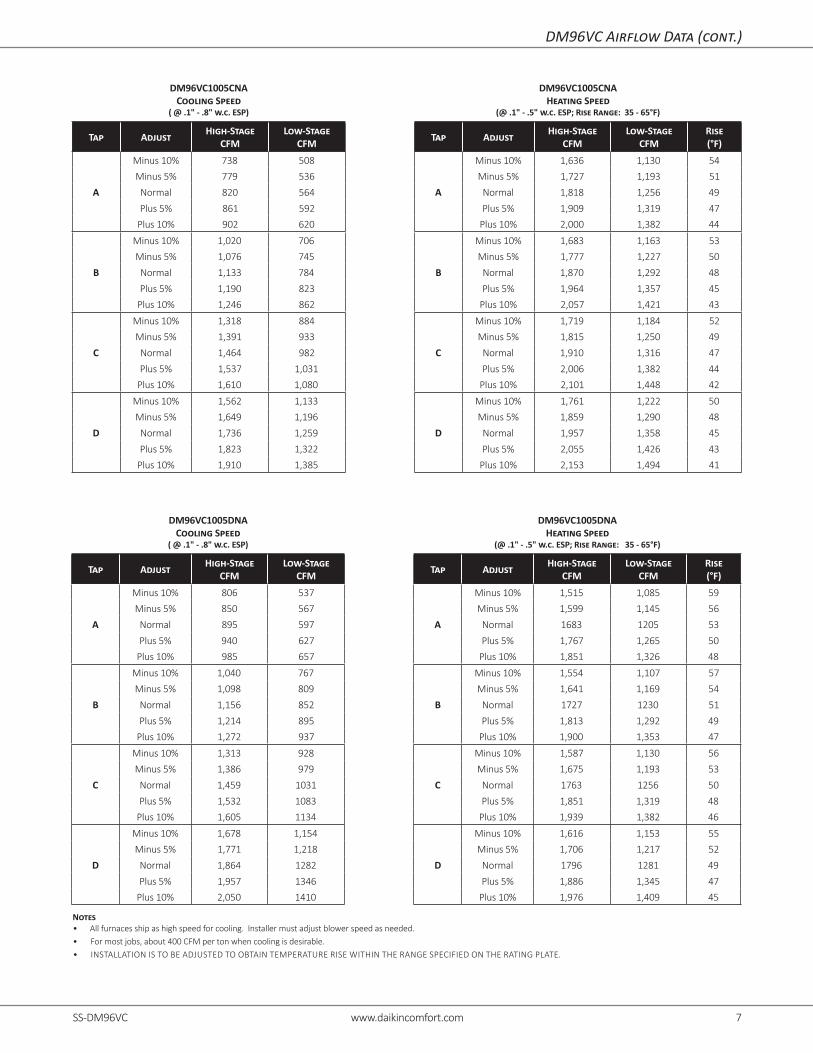
DM96VC Airflow Data (cont.)
DM96VC1005CNACooling Speed
( @ .1" - .8" w.c. ESP)
DM96VC1005CNAHeating Speed
(@ .1" - .5" w.c. ESP; Rise Range: 35 - 65°F)
Tap Adjust High-StageCFM
Low-StageCFM Tap Adjust High-Stage
CFMLow-Stage
CFMRise(°F)
A
Minus 10% 738 508
A
Minus 10% 1,636 1,130 54Minus 5% 779 536 Minus 5% 1,727 1,193 51
Normal 820 564 Normal 1,818 1,256 49Plus 5% 861 592 Plus 5% 1,909 1,319 47
Plus 10% 902 620 Plus 10% 2,000 1,382 44
B
Minus 10% 1,020 706
B
Minus 10% 1,683 1,163 53Minus 5% 1,076 745 Minus 5% 1,777 1,227 50Normal 1,133 784 Normal 1,870 1,292 48Plus 5% 1,190 823 Plus 5% 1,964 1,357 45
Plus 10% 1,246 862 Plus 10% 2,057 1,421 43
C
Minus 10% 1,318 884
C
Minus 10% 1,719 1,184 52Minus 5% 1,391 933 Minus 5% 1,815 1,250 49
Normal 1,464 982 Normal 1,910 1,316 47Plus 5% 1,537 1,031 Plus 5% 2,006 1,382 44
Plus 10% 1,610 1,080 Plus 10% 2,101 1,448 42
D
Minus 10% 1,562 1,133
D
Minus 10% 1,761 1,222 50Minus 5% 1,649 1,196 Minus 5% 1,859 1,290 48
Normal 1,736 1,259 Normal 1,957 1,358 45Plus 5% 1,823 1,322 Plus 5% 2,055 1,426 43
Plus 10% 1,910 1,385 Plus 10% 2,153 1,494 41
DM96VC1005DNACooling Speed
( @ .1" - .8" w.c. ESP)
DM96VC1005DNAHeating Speed
(@ .1" - .5" w.c. ESP; Rise Range: 35 - 65°F)
Tap Adjust High-StageCFM
Low-StageCFM Tap Adjust High-Stage
CFMLow-Stage
CFMRise(°F)
A
Minus 10% 806 537
A
Minus 10% 1,515 1,085 59Minus 5% 850 567 Minus 5% 1,599 1,145 56Normal 895 597 Normal 1683 1205 53Plus 5% 940 627 Plus 5% 1,767 1,265 50
Plus 10% 985 657 Plus 10% 1,851 1,326 48
B
Minus 10% 1,040 767
B
Minus 10% 1,554 1,107 57Minus 5% 1,098 809 Minus 5% 1,641 1,169 54
Normal 1,156 852 Normal 1727 1230 51Plus 5% 1,214 895 Plus 5% 1,813 1,292 49
Plus 10% 1,272 937 Plus 10% 1,900 1,353 47
C
Minus 10% 1,313 928
C
Minus 10% 1,587 1,130 56Minus 5% 1,386 979 Minus 5% 1,675 1,193 53
Normal 1,459 1031 Normal 1763 1256 50Plus 5% 1,532 1083 Plus 5% 1,851 1,319 48
Plus 10% 1,605 1134 Plus 10% 1,939 1,382 46
D
Minus 10% 1,678 1,154
D
Minus 10% 1,616 1,153 55Minus 5% 1,771 1,218 Minus 5% 1,706 1,217 52
Normal 1,864 1282 Normal 1796 1281 49Plus 5% 1,957 1346 Plus 5% 1,886 1,345 47
Plus 10% 2,050 1410 Plus 10% 1,976 1,409 45
Notes• All furnaces ship as high speed for cooling. Installer must adjust blower speed as needed.• For most jobs, about 400 CFM per ton when cooling is desirable.• INSTALLATION IS TO BE ADJUSTED TO OBTAIN TEMPERATURE RISE WITHIN THE RANGE SPECIFIED ON THE RATING PLATE.

8 www.daikincomfort.com SS-DM96VC SS-DM96VC www.daikincomfort.com 9
DM96VC1205DNACooling Speed
( @ .1" - .8" w.c. ESP)
DM96VC1205DNAHeating Speed
(@ .1" - .5" w.c. ESP; Rise Range: 35 - 65°F)
Tap Adjust High-StageCFM
Low-StageCFM Tap Adjust High-Stage
CFMLow-Stage
CFMRise(°F)
A
Minus 10% 780 492
A
Minus 10% 1,702 1,196 63Minus 5% 824 520 Minus 5% 1,796 1,263 59
Normal 867 547 Normal 1,891 1,329 56Plus 5% 910 574 Plus 5% 1,986 1,395 54
Plus 10% 954 602 Plus 10% 2,080 1,462 51
B
Minus 10% 1,044 748
B
Minus 10% 1,746 1,226 61Minus 5% 1,102 789 Minus 5% 1,843 1,294 58
Normal 1,160 831 Normal 1,940 1,362 55Plus 5% 1,218 873 Plus 5% 2,037 1,430 52
Plus 10% 1,276 914 Plus 10% 2,134 1,498 50
C
Minus 10% 1,320 918
C
Minus 10% 1,771 1,251 60Minus 5% 1,394 969 Minus 5% 1,870 1,321 57
Normal 1,467 1,020 Normal 1,968 1,390 54Plus 5% 1,540 1,071 Plus 5% 2,066 1,460 52
Plus 10% 1,614 1,122 Plus 10% 2,165 1,529 49
D
Minus 10% 1,719 1,150
D
Minus 10% 1,825 1,296 58Minus 5% 1,815 1,214 Minus 5% 1,927 1,368 55
Normal 1,910 1,278 Normal 2,028 1,440 53Plus 5% 2,006 1,342 Plus 5% 2,129 1,512 50
Plus 10% 2,101 1,406 Plus 10% 2,231 1,584 48
DM96VC Airflow Data (cont.)
Notes• All furnaces ship as high speed for cooling. Installer must adjust blower speed as needed.• For most jobs, about 400 CFM per ton when cooling is desirable.• INSTALLATION IS TO BE ADJUSTED TO OBTAIN TEMPERATURE RISE WITHIN THE RANGE SPECIFIED ON THE RATING PLATE.

8 www.daikincomfort.com SS-DM96VC SS-DM96VC www.daikincomfort.com 9
Wiring Diagram
Wiri
ng i
s su
bjec
t to
cha
nge.
Alw
ays
refe
r to
the
wiri
ng d
iagr
am o
n th
e un
it fo
r th
e m
ost
up-t
o-da
te w
iring
.⚠
War
ning
Hig
h Vo
ltage
: D
isco
nnec
t al
l po
wer
bef
ore
serv
icin
g or
ins
talli
ng t
his
unit.
Mul
tiple
pow
er
sour
ces
may
be
pres
ent.
Failu
re to
do
so m
ay c
ause
pro
pert
y da
mag
e, p
erso
nal i
njur
y, o
r de
ath.⚡
0140F02006-E
FRONT COVER
PRESSURE SWITCH
NO
C
SEE NOTE 6
AUX
FUSE 3 A
MICRO
TO
PS2 (12)
TR (11)
G
HI
C
TH (4)
24V TH
ER
MO
ST
AT C
ON
NE
CTIO
NS
VALVE
GAS
W2
TRANSFORMER
HLI (1)
Y2
Y1HLO (10)
GND (5)
O
MVL (13)
NO
W1
C
R
CONTROLSAUTO RESET AUXILIARY LIMIT
LIMIT CONTROLS
MANUAL RESET ROLLOUTPRESS. SWTICH
HIGH FIRE
C
PSO (7)
SWITCH
LOW FIRE PRESS.
MVH (14)
DEHUM
GND
PS1 (2)
LIMIT CONTROL
AUTO RESET PRIMARY24 VAC
NO
PM
MVC (8)
INTEGRATED CONTROL MODULE
C
BLWR
AIRINDOOR
CIRCULATORTX (3)
RX (2)
+ VDC (1)
GND (4)R
TO
MICRO
TO
TO +VDC
EAC
HUMIDIFIER
HUM-IN
ID
NEUTRAL
WIRING TO UNIT
L
INT
EG
RA
TE
D C
ON
TRO
L MO
DU
LE
HOT SURFACE
INDUCTOR COIL
GND
BLWR
NEUTRAL
WARNING:
GROUNDED.
OVERCURRENT PROTECTION DEVICE
MUST BE PROPERLY
SWITCH
NEUTRAL
ELECTRONIC
AIR
(ON SOME MODELS)
IGN
IND HI
DISCONNECT
FS
POLARIZED AND
NEUTRAL
LINE
NEUTRAL
JUNCTION BOX
BLWR
IND LO
N
HUMIDIFIER
INDOOR
AIR CLEANER
HUM
DOOR
NEUTRAL
INTE
GR
AT
ED
CO
NTR
OL M
OD
ULE
TO 115VAC/ 1Ø /60 HZ POWER SUPPLY WITH
115 VAC
HUM-OUT
IGNITER
CIRCULATOR
BEFORE SERVICING.
FLAME SENSOR
DISCONNECT POWER
LINE
GND
OU
TH
UM
-
IN HU
M-
WH/PU
CONT FAN
COOL AF
COOL PRFL
T-STAT
DEHUM ENABLE
HEAT AF
TRIM %
DIP
SW
ITC
HE
STRIM ENABLE
HEAT OFF DLY
OR
BR
BK
WH
WH
WH
WH
PU
GY
YL
OR
BR
PK
PK
WH
WHWH
BK
BK
RD
WH B
K
BR
PU
GYYL
GY
GY
BROR
PK
GN
OR
OR
OR
RD
BK
GY
BL
RD
WH
WH
98
12
1
15
11
14
7
2
54
13
3
6
10
DE
HU
M
W2C1 Y12 R
W1
MO
DU
LE
CO
NTR
OL
INT
EG
RA
TE
D
TWO
-ST
AG
E
EA
C
HU
M
Y2
CO
NN
EC
TO
R
4 CIR
CU
IT M
OTO
R5 C
IRC
UIT
CO
NN
EC
TOR
G
NOTE 5
SEE
BL
O
LED'SDIAGNOSTIC
4
FS
1
BK
5
3
24 V THERMOSTAT CONNECTIONS
NEUTRAL
1
3
2
LINE
FUSE
4
2
3 A
24 V
NO
2
1. SET HEAT ANTICIPATOR ON ROOM THERMOSTAT AT 0.7 AMPS.
LIMIT CONTROL
AUXILIARY
AUTO RESET
PK
WARNING:DISCONNECT
TRANSFORMER40 VA
PU
GY
N
NO
3
BR
4. UNIT MUST BE PERMANENTLY GROUNDED AND CONFORM TO N.E.C. AND LOCAL CODES.
COLOR CODES:
1
E SWITCH
PRESSUR
LOW FIRE
SENSOR
FLAME
GN GREEN
GR
PRESSURE SWITCH
FRONT COVER
C
VAC
TO UNIT MUST BE
1
BL
RD
AND GROUNDED.
1
115
WH
SWITCH (PRESS.)
FIELD SPLICE
FIELD GNDLOW VOLTAGE FIELD
3
GN
BL
BRWH
NO
LIMIT CONTROL
AUTO RESET PRIMARY
WH
1
OR
RD REDGY GRAY
40 kBTU)
CONTROLS (SINGLE CONTROL ON
MANUAL RESET ROLLOUT LIMIT
WH
L
PU
NOTES:
GY
PK
BK5
SWITCH ASSEMBLY
ID BLOWER TWO-STAGE PRESSURE
OR
WH
SERVICING. WIRING
EQUIPMENT GND
(ON SOME MODELS)
INTERNAL TO
SWITCH
PRESSURE
HIGH FIRE
PROT. DEVICE
INTEGRATED CONTROL
PK
C. USE COPPER CONDUCTORS ONLY. AT LEAST 105
IT MUST BE REPLACED WITH WIRING MATERIAL HAVING A TEMPERATURE RATING OF
3. IF ANY OF THE ORIGINAL WIRE AS SUPPLIED WITH THE FURNACE MUST BE REPLACED,
PU
PLUG CONNECTION
2
4
BK
C
DOOR OPEN)
(OPEN WHEN
DOOR SWITCH
COMPARTMENT
BLOWER
SWITCH (TEMP.)
GND
1
BLOWERCIRCULATOR
PU PURPLE
JUNCTION
OR
40 VA
PK PINK
Ø /60 HZ
DISCONNECT
(WHITERODGERS)
GAS VALVE
TWO STAGE
2. MANUFACTURER'S SPECIFIED REPLACEMENT PARTS MUST BE USED WHEN SERVICING.
OVERCURRENT
HI VOLTAGE (115V)
CONNECTOR
2 CIRCUIT
LOW VOLTAGE (24V)
YL
GND
VAC
CH
AS
SIS
GR
OU
ND
2
3
4
IGNITER
SURFACE
HOT
2
GND
BK BLACK
SETUP IS DONE WITHIN COMMUNICATING THERMOSTAT)LEGACY MODE) OR INDEPENDENTLY FROM HEAT CALL (COMMUNICATING MODE ONLY -TERMINALS TO RUN HUMIDIFIER DURING HEAT CALL ( COMMUNICATING MODE ORHEAT CALL (COMMUNICATING OR LEGACY MODES). USE HUM-IN AND HUM-OUT
6. HUMIDIFIER INSTALLATION OPTIONS: USE HUM TERMINAL TO RUN HUMIDIFIER DURING
FOR MORE THAN 2 SECONDS WHILE IN STANDBY (NO THERMOSTAT INPUTS)
5. TO RECALL THE LAST 6 FAULTS, MOST RECENT TO LEAST RECENT, DEPRESS SWITCH
YL
PU
C
INDUCTOR COIL
BL BLUE
2
C
BLOWER
DRAFT
INDUCED
BK
WH WHITE
PM
BK
24
BLOWER COMPARTMENT
115 VAC/ 1
OVERCURRENT
BK
BR BROWN
YL YELLOW
3
HI VOLTAGE FIELD
HARNESS
ECM MTR
OR ORANGE
HI
TERMINAL
OR
POWER BEFORE
IGNITER
RD
BK
TO
RD
POWER SUPPLY WITH
BURNER COMPARTMENT
PROTECTION DEVICE
PROPERLY POLARIZED
WH
BK
JUN
CT
ION
BO
XG
R
GN
D
GND
BL
GY
BK
RD
10 www.daikincomfort.com SS-DM96VC SS-DM96VC www.daikincomfort.com 11
Notes

10 www.daikincomfort.com SS-DM96VC SS-DM96VC www.daikincomfort.com 11
Notes

12 www.daikincomfort.com SS-DM96VC SS-DM96VC www.daikincomfort.com PB
Our continuing commitment to quality products may mean a change in specifications without notice. ©2021 • Houston, Texas • Printed in the USA
Notes