dl5000 dissolved oxygen (d.o.) probe user’s manual definition earth ground. functional earth...
TRANSCRIPT

Industrial Process Control
DL5000 Dissolved Oxygen (D.O.) ProbeUser’s Manual
70-82-25-1145/02

ii DL500 Dissolved Oxygen (D.O.) Probe – User’s Manual 5/02
Notices and TrademarksCopyright 2002 by Honeywell
May, 2002
Warranty/RemedyHoneywell warrants goods of its manufacture as being free of defective materials and faultyworkmanship. Contact your local sales office for warranty information. If warranted goods arereturned to Honeywell during the period of coverage, Honeywell will repair or replace withoutcharge those items it finds defective. The foregoing is Buyer's sole remedy and is in lieu of allother warranties, expressed or implied, including those of merchantability and fitness for aparticular purpose. Specifications may change without notice. The information we supply isbelieved to be accurate and reliable as of this printing. However, we assume no responsibility forits use.
While we provide application assistance personally, through our literature and the Honeywellweb site, it is up to the customer to determine the suitability of the product in the application.
Industrial Process ControlHoneywell
1100 Virginia DriveFort Washington, PA 19034
DirectLine is a trademark of HoneywellOther brands or product names are trademarks of their respective owners
5/02 DL5000 Dissolved Oxygen (D.O.) Probe – User’s Manual iii
About This Document
AbstractThis manual provides description, specification, installation, mounting,maintenance and troubleshooting information for the Honeywell DL5000Dissolved Oxygen (D.O.) Probe.
Contacts
World Wide WebThe following lists Honeywell’s World Wide Web sites that will be of interest toour customers.
Honeywell Organization WWW Address (URL)
Corporate http://www.honeywell.com
Industrial Process Control http://www.honeywell.com/ipc
TelephoneContact us by telephone at the numbers listed below.
Organization Phone Number
United States andCanada
Honeywell 1-800-423-9883 Tech. Support1-888-423-9883 Q&A Faxback
(TACFACS)
1-800-525-7439 Service
Symbol DefinitionsThe following table lists any symbols used in this document to denote certainconditions.
Symbol Definition
Earth Ground. Functional earth connection. NOTE: This connection shallbe bonded to Protective earth at the source of supply in accordance withnational and local electrical code requirements.

iv DL500 Dissolved Oxygen (D.O.) Probe – User’s Manual 5/02
Contents
1. INTRODUCTION ................................................................................................... 11.1 Overview........................................................................................................................11.2 Probe Description...........................................................................................................11.3 Operating Principal.........................................................................................................1
2. SPECIFICATIONS AND MODEL SELECTION GUIDE ........................................ 22.1 Specifications.................................................................................................................22.2 Model Selection Guide ...................................................................................................3
3. INSTALLATION .................................................................................................... 43.1 Mounting and Wiring ......................................................................................................4
DL424/425 Integral Mounting............................................................................................4DL424/425 Remote Mounting ...........................................................................................5Series 7020 Remote Mounting and Wiring........................................................................7Probe System Check ........................................................................................................8System Check for Probe with Model 7020 ........................................................................8
3.2 Probe Mountings ............................................................................................................9Wastewater Submersion...................................................................................................9In-line Flow Mounting......................................................................................................10Flow Through Mounting ..................................................................................................10Mounting Recommendation for Easy Calibration in Boiler Control Loop .........................12
4. MAINTENANCE .................................................................................................. 134.1 Introduction ..................................................................................................................13
Inert Fouling: ..................................................................................................................13Biologically Active Slime: ................................................................................................13
4.2 To Clean ......................................................................................................................144.3 O-Ring Replacement....................................................................................................144.4 Probe Storage..............................................................................................................14
Short term.......................................................................................................................14Long term .......................................................................................................................14
4.5 Packing Probe for Shipment or Storage .......................................................................14
5. TROUBLESHOOTING ........................................................................................ 155.1 Diagnostic Error Messages DL424/425 ........................................................................155.2 Troubleshooting 7020 Analyzer....................................................................................175.3 Processes Containing Carbon Dioxide .........................................................................175.4 Leak Detection in PPB Applications .............................................................................18
5/02 DL5000 Dissolved Oxygen (D.O.) Probe – User’s Manual v
TablesTable 3-1 Integral Mounting Procedure ( Figure 3-1)____________________________________ 4Table 3-2 Remote Mounting and Wiring Procedure for DL5000 Probes____________________ 5Table 5-1 Online Diagnostic Errors __________________________________________________ 15
FiguresFigure 3-1 Integral Mounting ____________________________________________________4Figure 3-2 Remote Wiring ______________________________________________________6Figure 3-3 Connect/Disconnect Sequence for the Series 7020 D.O. Analyzer ______________7Figure 3-4 Waste Water Mounting ________________________________________________9Figure 3-5 In-Line Mounting Kit _________________________________________________10Figure 3-6 Flow Through Mounting ______________________________________________11Figure 3-7 Mounting Recommendation for Easy Calibration in Boiler Control Loop _________12

vi DL500 Dissolved Oxygen (D.O.) Probe – User’s Manual 5/02

Introduction
5/02 DL5000 Dissolved Oxygen (D.O.) Probe – User’s Manual 1
1. Introduction
1.1 OverviewThis document provides description, specification, installation, mounting,maintenance, and trouble shooting information for the Honeywell DL5000Dissolved Oxygen (D.O.) probe. This probe can be used with the DL424, DL425,or the 7020 Series Dissolved Oxygen analyzers.
1.2 Probe DescriptionThe Honeywell probe is housed in either PVC or Stainless steel casing. One endhas a 1” NPT male thread for mounting. The sensor extends from the housingand is covered by a protective guard (of the same material as the casing) whichallows sample entry while preventing physical damage.The probe has permanent electrolyte which is sealed at the rear with anexpansion chamber to compensate for pressure changes. The sensor assemblyis permanently potted into the housing and is not field replaceable. Operationalservice in wastewater applications should consist of an occasional wash toremove any large deposits at the sensor end. This can usually be accomplishedwithout removing the protective guard. If the protective guard is removed,additional care must be taken to minimize the chance of puncturing a hole in theprobe membrane. See Probe Maintenance section for proper cleaningprocedures.Physically the probe consists of three electrodes and a thermistor fortemperature measurement and compensation. Two electrodes are interspacedon a supporting substrate and covered with an electrolyte; these electrodes areconnected as anode and cathode. The third or reference electrode is mounted inthe center of the electrode support and is also in contact with the electrolyte.The anode and cathode perform the oxygen generation and reduction functionswhile the reference electrode maintains the correct electrochemical potential.
1.3 Operating PrincipalWhen the probe is placed into the sample stream, oxygen diffuses through themembrane and is reduced at the cathode, and an equal amount of oxygen isgenerated at the anode. The diffusion continues until the oxygen partial pressureon both sides of the membrane is equal and a balance exists. The electricalcircuit is designed such that the current necessary to maintain this equilibrium isconverted to read out the dissolved oxygen concentration in the solution.The reactions are as follows:At cathode: O2 + 4H+ + 4 e- � 2H2OAt anode: 2H2O � O2 + 4H+ + 4 e-
Result: No net reaction

Specifications
2 DL500 Dissolved Oxygen (D.O.) Probe – User’s Manual 5/02
2. Specifications and Model Selection Guide2.1 Specifications
Normal OperatingTemperature Range: 2 – 60 �C (35.6 – 140�F)Storage Temperature: 2 – 60 �C (35.6 – 140�F) (See Attention)Maximum Flow Rate: No dependence on stirring or flow. However, a
minimal flow of 100 ml/min is expected toprovide a “flowing” sample.for flow through mounting: 300 ml/minfor in-line mounting: 5 gal/min
(18.9 liter/min) in a 1” Schedule 40 Line
for submersion mounting: Not applicable
Maximum Pressure: 30 psi (207 kPa) for PVC probe50 psi (345 kPa) for SS probe
Response time: 90% in 60 seconds (after Probe Warm-up)Probe Accuracy in parts per billion (ppb) measurements:
±5% or 2 ppb whichever is greater atcalibration conditions, after stabilizationin parts per million (ppm) measurements:±0.2 ppm at calibration conditions, afterstabilization
Probe Materials of Construction: PVC or Stainless Steel with a 20 ft.(6.1m) waterproof cable.The PVC model is also available with a 100ft.(30.48m) waterproof cable.
Probe Dimensions(same for PVC & SS): 8 .62” long X 1.315” OD (219 X 34 mm)Probe Weight: PVC 1.24 lb (0.6 kg)
SS: 3.5 lb (1.5 kg)
ATTENTION
Probe membrane must be kept wetted both in the process and during storage. SeeStorage under Maintenance section.
The silicone membrane surrounding the D.O. probe is permanent. If thismembrane is removed by user for any reason, the warranty on the D.O. probe isvoided

Specifications
5/02 DL5000 Dissolved Oxygen (D.O.) Probe – User’s Manual 3
2.2 Model Selection GuideInstructions
Select the desired key number. The arrow to the right marks the selection available.Make one selection from Tables I & II using the column below the proper arrow.A dot ( ) denotes unrestricted availability.
Key Number II_ _ _ _ _ _ _ _ _ _ _ _ _
KEY NUMBER
DL5000 Dissolved Oxygen Probe - Parts Per Billion DL5PPBDL5000 Dissolved Oxygen Probe - Parts Per Million DL5PPM
TABLE I - Probe Construction:
TABLE II - Options
Availability PPB PPM Selection
_ _W3
LN_ _
00_ _
SS_ _
DESCRIPTION
Material of Construction
Remote
Remote
PVC316 Stainless Steel
PVC316 Stainless Steel
PVC
TaggingLinen Customer I.D. Tag:
3 lines w/22 characters/line
Standard Warranty
None
20'
100'
1 Year Extended Warranty
2 Years Extended Warranty
Stainless Steel Customer I.D. Tag 3 lines w/22 characters/line
-I
-
Mounting
Integral
Extended Warranty Against Manufacturing
Defects
100200300400700
_ _00
_ _W2
Cable LengthNone

Installation
4 DL500 Dissolved Oxygen (D.O.) Probe – User’s Manual 5/02
3. Installation
3.1 Mounting and WiringThe following section describes the installation of the Honeywell D. O. probe.
DL424/425 Integral MountingTable 3-1 Integral Mounting Procedure ( Figure 3-1)
Step Procedure
1 Connect the probe to the process source (using the appropriate mountingfrom those supplied for the DL5000).Make sure that the final position of the installed electronics moduleallows the display to be easily viewed by personnel.
2 Apply a thin film of silicon grease on the ID of the electronics module’sprobe mounting cavity.
3 Align the slots on the electronics module with those on the probe andpress down to connect the electronics to the probe.
4 Tighten the locking screw on the bottom rear of the electronics module.
Step 1
Step 2
Step 3 Step 4
Locking Screw inRear of Housing
ElectronicsModule
Probe
Figure 3-1 Integral Mounting
Installation
5/02 DL5000 Dissolved Oxygen (D.O.) Probe – User’s Manual 5
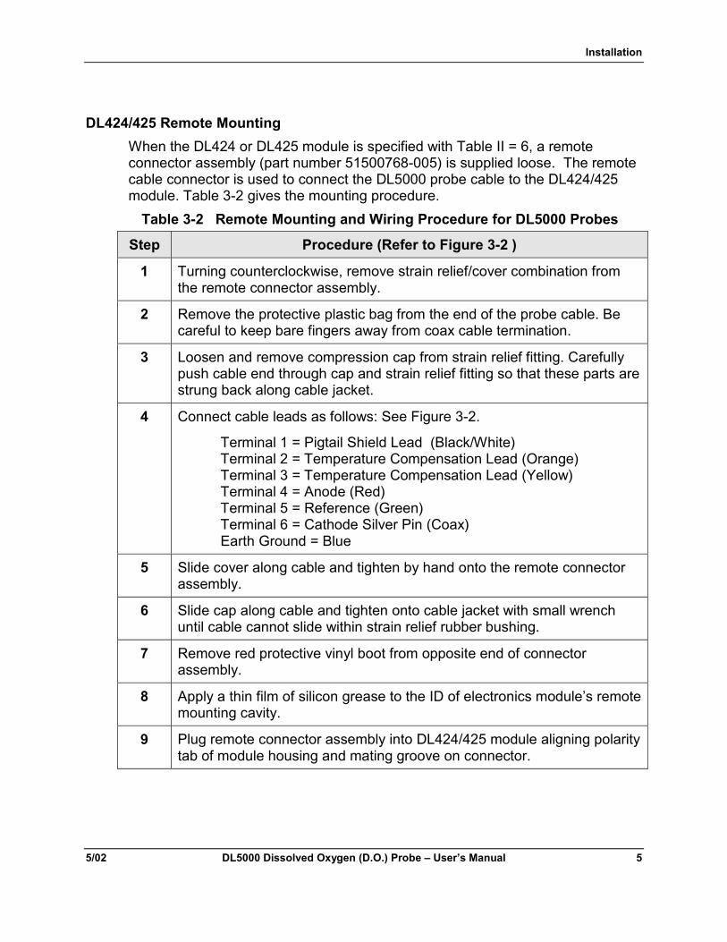
DL424/425 Remote MountingWhen the DL424 or DL425 module is specified with Table II = 6, a remoteconnector assembly (part number 51500768-005) is supplied loose. The remotecable connector is used to connect the DL5000 probe cable to the DL424/425module. Table 3-2 gives the mounting procedure.
Table 3-2 Remote Mounting and Wiring Procedure for DL5000 Probes
Step Procedure (Refer to Figure 3-2 )
1 Turning counterclockwise, remove strain relief/cover combination fromthe remote connector assembly.
2 Remove the protective plastic bag from the end of the probe cable. Becareful to keep bare fingers away from coax cable termination.
3 Loosen and remove compression cap from strain relief fitting. Carefullypush cable end through cap and strain relief fitting so that these parts arestrung back along cable jacket.
4 Connect cable leads as follows: See Figure 3-2.
Terminal 1 = Pigtail Shield Lead (Black/White)Terminal 2 = Temperature Compensation Lead (Orange)Terminal 3 = Temperature Compensation Lead (Yellow)Terminal 4 = Anode (Red)Terminal 5 = Reference (Green)Terminal 6 = Cathode Silver Pin (Coax)Earth Ground = Blue
5 Slide cover along cable and tighten by hand onto the remote connectorassembly.
6 Slide cap along cable and tighten onto cable jacket with small wrenchuntil cable cannot slide within strain relief rubber bushing.
7 Remove red protective vinyl boot from opposite end of connectorassembly.
8 Apply a thin film of silicon grease to the ID of electronics module’s remotemounting cavity.
9 Plug remote connector assembly into DL424/425 module aligning polaritytab of module housing and mating groove on connector.

Installation
6 DL500 Dissolved Oxygen (D.O.) Probe – User’s Manual 5/02
1
2
3
6
5
4
123456
Pigtail Shield (Black/White)Temperature Compensation (Orange)Temperature Compensation (Yellow)Anode (Red)Reference (Green)Cathode Silver Pin (Coax)Earth Ground (Blue)
CompressionCap
StrainRelief
Cover
ProtectiveVinyl Boot(remove)
1
2
MODE
Remote Electronics forModule DL5000 Dissolved Oxygen Probes
Remote Wiring Cable
Probe
ElectronicsModule
DL5000 Probe Electronics
Figure 3-2 Remote Wiring

Installation
5/02 DL5000 Dissolved Oxygen (D.O.) Probe – User’s Manual 7
Series 7020 Remote Mounting and WiringWhen connecting the probe to the Series 7020 Analyzer, the probe wiring shouldalways be kept separated from the AC power wiring. After the analyzer andprobe have been securely mounted, the probe should be connected to theanalyzer.Before wiring, remove the protective insulator tape from the green lead. To makewiring easier on the 7020 Series analyzer, loosen the screw at the bottom ofthe terminal board and remove the terminal block from the panel while wiring.Figure 3-3 gives the sequence for connecting and disconnecting the probe fromthe 7020 Series analyzer.
CAUTIONWhen installing the probe the wiring must be done in the order shown in Figure 3-3,even if the analyzer is not powered. This is because the battery backup card iscontinuously supplying a voltage (bias) to the terminals.
ANODE (Red)REF (Green)CATH SILVER PIN (Coax)THERM+ (Yellow)THERM – (Orange)SHIELD (White/Black)ALL+ALL –
40
33TB5Connecting – Shield wire first,
then in this order RedGreenCoaxYellowOrange
Disconnecting – Go in reverseOrange - firstYellowCoaxGreenRedShield Wire
Figure 3-3 Connect/Disconnect Sequence for the Series 7020 D.O. Analyzer

Installation
8 DL500 Dissolved Oxygen (D.O.) Probe – User’s Manual 5/02
Probe System CheckWhen the probe is connected for the first time, replaced or just disconnected andreconnected, a conditioning period of 24 hours is needed before the probe canmake an accurate measurement. During this time period, the probe must be keptwetted by either putting it in the process water or in a container of water exposedto air. For ppb applications, it is recommended that process conditions areused. Once the 24 hour period has elapsed, the probe can be calibrated. Thecalibration instructions are as follows:1. Remove probe from either the process or container of water and put in
ambient air. If probe was in process wastewater, clean probe first percleaning instructions under the maintenance section.If the probe is in a ppb process, expose the probe to air for 2 - 4 hours beforedoing an Air calibration.
2. Perform an Air calibration or Sample calibration. Make sure probetemperature is stable before performing an Air calibration. If temperature isnot stable, the Air calibration will fail.
ATTENTION
Do not perform an Air calibration on a windy day or during freezing temperatures.The temperature will not stabilize on a windy day and freezing temperatures willcause the probe’s electrolyte to freeze and the membrane to crack.
3. At completion of a successful air or sample calibration, put probe into processwater.
After the initial calibration, the probe should only be removed from the processfor periodic cleaning and calibration. The recommended cleaning schedule forppb applications is monthly and for ppm applications it is bimonthly. If theprobe’s response has slowed or readings are lower than expected prior to therecommended cleaning schedule, the probe may need to be cleaned morefrequently. The recommended calibration schedule for ppb and ppmapplications is monthly. If individual plant maintenance schedules require it, theprobe may be calibrated more frequently.
System Check for Probe with Model 7020Perform a system check upon completion of all wiring. AC noise in the variousanalyzer output connections may affect the bias amplifier resulting in a DCcurrent in the reference lead. This DC current will cause dissolution on the silverreference electrode over time resulting in a shortened probe life.See Appendix A in the 7020 Operator manual for directions on Noise testing.

Installation
5/02 DL5000 Dissolved Oxygen (D.O.) Probe – User’s Manual 9
3.2 Probe Mountings
Wastewater SubmersionVarious mounting are available for the Honeywell D.O. probe. Figure 3-4 showsthe probe mounting kit for Wastewater Submersion. Except for the 1” schedule40 PVC pipe or conduit, this kit contains all pieces needed to mount the probe to1-1/2” diameter safety railings. The length of the pipe or conduit governs thedepth of the probe immersion while the angle piece governs the horizontaldistance. To minimize debris build-up, place the probe into the process at a 45 �angle from the horizontal pipe railing. The cable can be routed though thesupporting pipe or tied to its side.If the kit is not used and plastic pipe is preferred, use 1” to 1 ½” coupling. Theuse of the pipe is suggested to avoid whipping of the pipe when used in flowingor turbulent water.
D.O. Receiver
Pin Fitting (2 req’d)31063325(Note location of pins
1” Pipe Size
Eye Fitting (2 req’d)31063329
1” X 1”Female
Coupling31063330
Wrench 31063326
D.O. ProbeAssembly
Single Socket Tee31063328
1 1/2” Pipe Size6” to 8” Long
1 1/2” Pipe Size24” to 30” Long
Clamp on Tee (2 req’d)31063327
Figure 3-4 Waste Water Mounting
Installation
10 DL500 Dissolved Oxygen (D.O.) Probe – User’s Manual 5/02
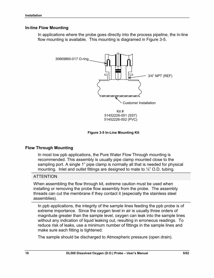
In-line Flow MountingIn applications where the probe goes directly into the process pipeline, the in-lineflow mounting is available. This mounting is diagramed in Figure 3-5.
30669860-017 O-ring
Customer Installation
3/4” NPT (REF)
Kit #51452226-001 (SST)51452226-002 (PVC)
Figure 3-5 In-Line Mounting Kit
Flow Through MountingIn most low ppb applications, the Pure Water Flow Through mounting isrecommended. This assembly is usually pipe clamp mounted close to thesampling port. A single 1” pipe clamp is normally all that is needed for physicalmounting. Inlet and outlet fittings are designed to mate to ¼” O.D. tubing.
ATTENTION
When assembling the flow through kit, extreme caution must be used wheninstalling or removing the probe flow assembly from the probe. The assemblythreads can cut the membrane if they contact it (especially the stainless steelassemblies).
In ppb applications, the integrity of the sample lines feeding the ppb probe is ofextreme importance. Since the oxygen level in air is usually three orders ofmagnitude greater than the sample level, oxygen can leak into the sample lineswithout any indication of liquid leaking out, resulting in erroneous readings. Toreduce risk of leaks, use a minimum number of fittings in the sample lines andmake sure each fitting is tightened.The sample should be discharged to Atmospheric pressure (open drain).

Installation
5/02 DL5000 Dissolved Oxygen (D.O.) Probe – User’s Manual 11
The flow through mounting is diagramed in Figure 3-6.
Kits51452187-001 Stainless Steel51452187-002 PVC
Male Compression Fittingfor 1/4 O.D. Tubing
Dissolved Oxygen Probe
Flow Through Adapter
Male Compression Fittingfor 1/4 O.D. Tubing
Inlet
9 1/2”
Replacement O-ring30669860-017
Outlet
1 5/16”
Figure 3-6 Flow Through Mounting

Installation
12 DL500 Dissolved Oxygen (D.O.) Probe – User’s Manual 5/02
Mounting Recommendation for Easy Calibration in Boiler Control LoopA "Trap" arrangement should be plumbed in the incoming flow to the DO probeso that if flow is shut off or an "Upstream" pipe opened, water will remain aroundthe tip of the probe. Keeping it moist on the outlet side, an arrangement such asa "TEE" should be made to assure that when the 3-way valve is opened (for AirCalibration), the water within the probe flows out. "Cracking" the fittings on theinlet side will achieve the same result as a 3-way valve, but repeated "Cracking"will cause wear on the parts and any additional handling may shorten the life ofthe probe.
AIR
DRAIN
DRAIN
PROBE
FLOWMETER
TRAP
3-WAYVALVE
FLOW
TEMP
PRESS
X
Figure 3-7 Mounting Recommendation for Easy Calibration in BoilerControl Loop
To avoid drying out the probe sensor when the sampling point is shut off, a watertrap should be made in the inlet piping

Maintenance
5/02 DL5000 Dissolved Oxygen (D.O.) Probe – User’s Manual 13
4. Maintenance
4.1 IntroductionThe Honeywell D. O. probe requires no internal probe maintenance. However,like all other probes, it does need to be cleaned periodically. After a long periodof use, the oxygen transfer may cease due to a coating buildup. This buildupmay consume or block the oxygen, increase the response time and / or reducethe probe accuracy. Cleaning the probe is easy and is normally accomplished byagitating the probe in a container of fluid. The cleaning fluid can vary from waterto a 10% HCl solution depending on the type of buildup or fouling encountered.
Inert Fouling:(ex. hair, grease, and solids) This type of fouling normally occurs in wastewaterapplications; however, rust-like contaminants may occur in ppb applications.When a significant amount of this debris is deposited on the probe, the responsetime of the probe slows down. Normal cleaning practices should restore probe tocorrect operation.
Biologically Active Slime:This type of fouling consists of biologically active slime adhering either loosely ortightly to the probe or the protective cap or both. This slime can be visible orinvisible and may produce a sticky feel to the probe and / or cap’s surface area.This type of fouling is usually characterized by the following performance: thesignal drifts slowly downward for several hours (or days) and then dropsprecipitously toward zero in a matter of a few hours or less. Proper air calibrationcan be restored only after very careful wiping of the probe tip or a 30 secondrinse in a 10% HCl solution. The time between cleanings can be extended byrelocating the probe to a cleaner environment (nearer the effluent) or relocatingthe probe to where the water is flowing faster. After these actions are taken, acleaning schedule should be established.
ATTENTION
Never use a brush to clean a Honeywell D.O. probe as it can cause a tear in theprobe membrane rendering it inoperable. This type of abuse is not covered underprobe warranty.

Maintenance
14 DL500 Dissolved Oxygen (D.O.) Probe – User’s Manual 5/02
4.2 To CleanCleaning should consist of the simplest of the following required to re-establishproper performance: 1.)Rinsing with water 2.) rinse with mild detergent followedby water 3.) rinse with 10% HCl followed by mild detergent followed by water. Ifthe probe must be wiped, carefully use a paper towel or cotton swab. Aftercleaning is completed, place the probe back into the process and allow 60minutes before a calibration.
4.3 O-Ring ReplacementTo replace the O-ring shown in Figure 3-6:1. Place the o-ring over the threads of either the flow through or in-line fitting.2. Silicone grease may be used to assist in O-ring installation.3. Attach the adapter to the probe. Be careful not to touch the probe
membrane.
4.4 Probe Storage
Short termThe Honeywell probe arrives from the factory with an red cap on the end of theprobe. This cap contains a 3% solution of Isopropyl alcohol and water. Thewater keeps the probe wetted until it is put into the process. The alcoholminimizes the growth of bacteria.
Long termIf the probe remains on the shelf for longer than 6 months, the solution inside thecap must be replaced. To do this, remove the side mounted, threaded pipe plugusing a 3/16 hex key wrench. Fill the hole with a fresh solution of 3% Isopropylalcohol and water, and replace the hex screw. This procedure keeps the probewetted and minimizes incidence of bacteria.
4.5 Packing Probe for Shipment or StorageWhen removing the probe from service for storage or shipment, replace the redcap that came with the probe. Fill the probe as described in Storage – Longterm. This prevents damage caused by long-term contact with the other probeleads.

Troubleshooting
5/02 DL5000 Dissolved Oxygen (D.O.) Probe – User’s Manual 15
5. Troubleshooting
5.1 Diagnostic Error Messages DL424/425When a diagnostic error or status condition occurs, the Online Display alternatesbetween measured DO and a text message.
Table 5-1 Online Diagnostic Errors
What you see What it is What to do
CnFG Configuration or Calibration data isdefective.
Reset unit or cycle power.
Second occurrence willshow FALt.
FALt Unit electronics are defective. Replace electronicsmodule.
These errors may occur when on-line DO Concentration or on-line Temperatureis displayed.
dOHI Measured DO is > 20 ppm/200 ppb Bring process to withinlimits
dOLo Measured DO is < 0.00 ppm/ppb Bring process to withinlimits
PrbE Probe is defective, wrong type, or notconnected.
Probe current is excessive with probevoltage near 0 volts.
Forces the output to burnout level(greater than 22 mA).
Check for an electricalshort between the anodeand the cathode.
Check the referenceelectrode connection.
When the source of theerror is removed, theerror will clear and theoutput will return tonormal operation.
T HI Measured temperature is > 60 �C Bring process to withinlimits
T LO Measured temperature is < 2.0 �C Bring process to withinlimits

Troubleshooting
16 DL500 Dissolved Oxygen (D.O.) Probe – User’s Manual 5/02
What you see What it is What to do
bErr Probe Bias Error:Probe current has exceeded expectedprobe current by 33% for at least 20seconds.
If the excessive current conditioncontinues after a manual probe bias ,the PrbE error is generated. If excessivecurrent is not present then the bErrremains.
Application related shift in probe biasvoltage
Remove the probe fromprocess and do a probebias calibration. In ppmapplications in processescontaining CO2, the probemay be left in the processand the Bias can bemanually adjusted.
Remove the probe fromthe process and do an AirCalibration
These errors may occur during Air, Sample and Probe Bias calibration andabort the calibration process.
FAIL These error messages are preceded bythe message “FAIL”ArnG Air Calibration failed due to a
measured probe current not in theacceptable range
Stbl Air Calibration failed due to inputmeasurement instability
bErr Bias voltage calibration failed dueto unacceptable input current.Replace Probe.
Press Mode to return toonline display.

Troubleshooting
5/02 DL5000 Dissolved Oxygen (D.O.) Probe – User’s Manual 17
5.2 Troubleshooting 7020 AnalyzerThe Honeywell 7020 Series Operator manual contains many tips for troubleshooting the 7020 Series analyzer. Consult the Matrix of Potential Problemsand Solutions under Section 5.2 in the Operator manual for information on yourparticular problem.In addition, the appendix section of the Honeywell 7020 Series Operator manualprovides information on various subjects related to the D.O. probe, including thefollowing topics:� Excess AC noise can result in a shorten probe life. To ensure that there
is no excess noise on the probe leads, use the procedure in Appendix A inthe 7020 manual – Noise Testing to test your probe installation.
� If a D.O. reading doesn’t seem correct, check that the probe and analyzerare working correctly by using the procedures provided in Appendix B in the7020 manual – Probe and Analyzer Tests.
� To confirm the D.O. measurement in air at a specific temperature,consult Appendix E in the 7020 manual – Percent Saturation Readout to getthe expected DO concentration in air or air saturated water at varioustemperatures. This information will confirm if the probe is giving a validmeasurement in air.
� If a leak is suspected in a ppb system, consult Appendix F in the 7020manual – Leak Detection in PPB Applications to understand how to use theD.O. probe to find a leak.
� Want proof that a D.O. probe can go down to zero ppbs? ConsultAppendix G in the 7020 manual – Procedure for Low level ppb DissolvedOxygen testing to confirm that your probe can get down to zero ppbs.
5.3 Processes Containing Carbon Dioxide When measuring D.O. in a process containing carbon dioxide (e.g. beer or soda)special procedures are required to protect the probe. To remove the probe fromthe line:1. Shut off sample line containing CO2.2. Purge the line containing the probe with fresh water at the same pressure for
15 minutes to remove the CO2 from the D. O. probe.3. Remove probe when convenient.
CAUTIONNot following this procedure will cause internal rupture of the membrane renderingthe probe inoperable, un-repairable and void of any probe warranty. For optimumperformance in this application, the bias voltage should be adjusted to measure450 mV instead 600 mV. Review the Series 7020 operator manuals for adjustingthe Probe Bias.

Troubleshooting
18 DL500 Dissolved Oxygen (D.O.) Probe – User’s Manual 5/02
5.4 Leak Detection in PPB ApplicationsBefore performing and air leak detection, it is necessary to determine that boththe probe and analyzer are working properly.First, check to see that the probe contains an O-ring. Per the probe directions, anO-ring must go into a probe that is used in ppb applications. This creates a tightseal between the probe and flow chamber.MAKE SURE THIS O-RING IS IN THE PROBE.1. Unless already in air, open the probe to air for 30 seconds.2. Put it back into the process again.3. Allow the DO to drift down to the 20-30 ppb range. The 20-30 ppb range was
chosen because the reading was low enough that the drift was small withrespect to the changes observed for various flow rates but high enough thatchanges could be observed.
4. At this range, vary the flow rate from 10 to 100 ml/min. These low flow rateswere selected for two reasons. The first, the tester many only have a 0 - 100ml/min flow indicator. The other reason, is a leak that exists at this low flow,will cause a change in the DO reading.
5. If the DO value at 10 ml/min exceeds the DO value at 100 ml/min, a leak ispresent in the sampling line.
6. Fixing the leak may require plastic tubing to be replaced with metal tubing,tape to be put on fittings, and/or fittings at the bottom of the probe to betighten securely.
7. Now, repeat Steps 2 - 6 until the flow can be changed from >100 ml/min to 10ml/min with no change in the DO value.

Troubleshooting
5/02 DL5000 Dissolved Oxygen (D.O.) Probe – User’s Manual 19


Sales and Service
For application assistance, current specifications, pricing, or name of the nearest Authorized Distributor,contact one of the offices below.
ARGENTINAHONEYWELL S.A.I.C.BELGRANO 1156BUENOS AIRESARGENTINATel. : 54 1 383 9290
ASIA PACIFICHONEYWELL ASIAPACIFIC Inc.Room 3213-3225Sun Kung Kai CentreN° 30 Harbour RoadWANCHAIHONG KONGTel. : 852 829 82 98
AUSTRALIAHONEYWELL LIMITED5 Thomas Holt DriveNorth Ryde SydneyNSW AUSTRALIA 2113Tel. : 61 2 353 7000AUSTRIA
HONEYWELL AUSTRIAG.m.b.H.Handelskai 388A1020 VIENNAAUSTRIATel. : 43 1 727 800
BELGIUMHONEYWELL S.A.3 Avenue de BourgetB-1140 BRUSSELSBELGIUMTel. : 32 2 728 27 11
BRAZILHONEYWELL DOBRAZILAND CIARua Jose Alves DaChunhaLima 172BUTANTA05360.050 SAO PAULOSPBRAZILTel. : 55 11 819 3755
BULGARIAHONEYWELL EOOD14, Iskarsko ChaussePOB 79BG- 1592 SofiaBULGARIATel : 359-791512/794027/ 792198
CANADAHONEYWELL LIMITEDTHE HONEYWELLCENTRE300 Yorkland Blvd.NORTH YORK, ONTARIOM2J 1S1CANADATel.: 800 461 0013Fax:: 416 502 5001
CZECHREPUBLICHONEYWELL, Spol.s.r.o.Budejovicka 1140 21 Prague 4Czech RepublicTel. : 42 2 6112 3434
DENMARKHONEYWELL A/SAutomatikvej 1DK 2860 SoeborgDENMARKTel. : 45 39 55 56 58
FINLANDHONEYWELL OYRuukintie 8FIN-02320 ESPOO 32FINLANDTel. : 358 0 3480101
FRANCEHONEYWELL S.A.Bâtiment « le Mercury »Parc Technologique de StAubinRoute de l’Orme(CD 128)91190 SAINT-AUBINFRANCETel. from France:01 60 19 80 00From other countries:33 1 60 19 80 00
GERMANYHONEYWELL AGKaiserleistrasse 39D-63067 OFFENBACHGERMANYTel. : 49 69 80 64444
HUNGARYHONEYWELL KftGogol u 13H-1133 BUDAPESTHUNGARYTel. : 36 1 451 43 00
ICELANDHONEYWELLHataekni .hfArmuli 26PO Box 8336128 reykjavikIcelandTel : 354 588 5000
ITALYHONEYWELL S.p.A.Via P. Gobetti, 2/b20063 Cernusco SulNaviglioITALYTel. : 39 02 92146 1
MEXICOHONEYWELL S.A. DECVAV. CONSTITUYENTES900COL. LOMAS ALTAS11950 MEXICO CITYMEXICOTel : 52 5 259 1966
THE NETHERLANDSHONEYWELL BVLaaderhoogtweg 181101 EA AMSTERDAMZOTHE NETHERLANDSTel : 31 20 56 56 911
NORWAYHONEYWELL A/SAskerveien 61PO Box 263N-1371 ASKERNORWAYTel. : 47 66 76 20 00
POLANDHONEYWELL Sp.z.o.oUI Domainewksa 4102-672 WARSAWPOLANDTel. : 48 22 606 09 00
PORTUGALHONEYWELLPORTUGAL LDAEdificio Suecia IIAv. do Forte nr 3 - Piso 32795 CARNAXIDEPORTUGALTel. : 351 1 424 50 00
REPUBLIC OF IRELANDHONEYWELLUnit 1Robinhood BusinessParkRobinhood RoadDUBLIN 22Republic of IrelandTel. : 353 1 4565944
REPUBLIC OFSINGAPOREHONEYWELL PTE LTDBLOCK 750E CHAICHEE ROAD06-01 CHAI CHEE IND.PARK1646 SINGAPOREREP. OF SINGAPORETel. : 65 2490 100
REPUBLIC OF SOUTHAFRICAHONEYWELLSouthern AfricaPO BOX 138Milnerton 7435REPUBLIC OF SOUTHAFRICATel. : 27 11 805 12 01
ROMANIAHONEYWELL OfficeBucharest147 Aurel Vlaicu Str.,Sc.Z.,Apt 61/62R-72921 BucharestROMANIATel : 40-1 211 00 76/211 79
RUSSIAHONEYWELL INC4 th Floor AdministrativeBuiliding of AO "Luzhniki"Management24 Luzhniki119048 MoscowRUSSIATel : 7 095 796 98 00/01
SLOVAKIAHONEYWELL LtdMlynske nivy 73PO Box 75820 07 BRATISLAVA 27SLOVAKIATel. : 421 7 52 47 400/425
SPAINHONEYWELL S.AFactoryJosefa Valcarcel, 2428027 MADRIDSPAINTel. : 34 91 31 3 61 00
SWEDENHONEYWELL A.B.S-127 86 SkarholmenSTOCKHOLMSWEDENTel. : 46 8 775 55 00
SWITZERLANDHONEYWELL A.G.Hertistrasse 28304 WALLISELLENSWITZERLANDTel. : 41 1 831 02 71
TURKEYHONEYWELLOtomasyon ve KontrolSistemlen San ve TicA.S.(Honeywell Turkey A.S.)Emirhan Cad No 144Barbaros Plaza C. BlokKat 18Dikilitas 80700 IstanbulTURKEYTel : 90-212 258 18 30
UNITED KINGDOMHONEYWELLUnit 1,2 &4 Zodiac HouseCalleva ParkAldermastonBerkshire RG7 8HWUNITED KINGDOMTel : 44 118 906 2600
U.S.A.HONEYWELL INC.INDUSTRIAL PROCESSCONTROLS1100 VIRGINIA DRIVEPA 19034-3260FT. WASHINGTONU.S.A.Tel. : 1-800-343-0228
VENEZUELAHONEYWELL CAAPARTADO 613141060 CARACASVENEZUELATel. : 58 2 239 0211


Industrial Process Control
Honeywell
1100 Virginia Drive
Fort Washington, PA 19034
70-82-25-114 0502 Printed in USA www.honeywell.com/ipc