dkt hfa network management interface operation manual...
TRANSCRIPT
High-power Fiber Amplifier Network Management Interface
Operation Manual
(ver 1.0)

Page 1 of 14
Table of Contents Table of Contents .........................................................................................................................1 Revision History ...........................................................................................................................2 Introduction ...................................................................................................................................3 Operation Manual .........................................................................................................................3
1. Web Service ......................................................................................................................3 1.1 HFA Monitor ............................................................................................................3 1.2 Status........................................................................................................................4 1.3 Network ....................................................................................................................5 1.4 DNS ...........................................................................................................................6 1.5 SNMP ........................................................................................................................7 1.6 System......................................................................................................................8 1.7 Password .................................................................................................................9
2. SNMP.................................................................................................................................10 2.1 SNMP Protocol MIB Definition .........................................................................11 2.2 Alarm Trap Definition .........................................................................................12

Page 2 of 14
Revision History Revision Date Description
1.0 20120428 Initial release

Page 3 of 14
Introduction This type of high power fiber amplifier produced by DKTCOMEGA Networks has been designed specifically for CATV optical transmission system. The CATV-HFA series provides up to 33dBm of total optical output power with excellent noise figure performance, and supports SNMP as well as Web Browser protocol. The available 10/100 Ethernet Interface enables online configuration of the products and offers customers good maneuverability.
Operation Manual
1. Web Service
Function: Web Server in HFA Device provides Http operating interface,which allows customers to read the basic HFA parameters and warning information with Internet Explorer. Web Browser default login name: admin Password: PASS
1.1 HFA Monitor
Input HFA IP address (example: 192.168.1.1) in the address column of the Windows IE Browser. The following window is displayed (Figure 1, Figure 2): Click ‘HFA Monitor’ to read the current parameters of HFA
Figure 1

Page 4 of 14
Figure 2
1.2 Status
Click ‘Status’ to read the current parameters of the device such as IP address, MAC
etc(see Figure 3)
Figure 3

Page 5 of 14
1.3 Network
Click ‘Network’ to go to Server setting window, in which parameters like IP Adress, Subnet,
Gateway etc can be set. Click ‘Submit’, new parameters are sent to the server. (see
Figure 4)
Figure 4
There are two configuration table columns displayed. One shows the current running
configuration, and the other shows the configuration that will take effect after the device
is rebooted.
The following items are required for the reboot to take effect:
DHCP Client On/Off
IP Address
Network Mask
DHCP Client ID
If the IP Address, Network Mask, Gateway, Hostname, and Domain have been configured
for the device and DHCP is turned on, the original configuration items are ignored.
DHCP will auto-discover and eclipse those configuration items.

Page 6 of 14
1.4 DNS
Click ‘DNS’ to configure DNS of the server. (see Figure 5)
Figure 5
This page displays the current configuration of the DNS subsystem. Users may configure
the Primary and Secondary static server addresses by themselves. If the current
configuration shows the address coming from HCP, the static address will be overrided
until the device is rebooted.

Page 7 of 14
1.5 SNMP
Click ‘SNMP’ to read and write the parameters of HFA via SNMP manager.
(see Figure 6)
Figure 6

Page 8 of 14
1.6 System
Click ‘System’ button to upload new firmware in order to update the current program in this
web page. (see Figure 7). It will take a few minutes to update program, please be patient
for it.
Figure 7
Be careful not to power off or reset the device while uploading new firmware. Once the
upload has completed and the new firmware has been verified and flashed, the device will
be rebooted automatically.

Page 9 of 14
1.7 Password
Click ‘Password’ Button to change user password in this web page. (see Figure 8),
Note that users may start a new browser to access the device if the password of user is
changed successfully.
Figure 8

Page 10 of 14
2. SNMP
Function: read and write the parameters of HFA via SNMP manager.
Default read community: public Default write community: admin The SNMP Agent located on the device follows standard SNMPv2 protocol. Users can
read or write the OIDs defined by SNMP protocol mib in the table below.

Page 11 of 14
2.1 SNMP Protocol MIB Definition
No. OID Content R/W Authority Value Type HFA Definition 1 1.3.6.1.4.1. 27304.89.2.1 SN Read Only String 2 1.3.6.1.4.1. 27304.89.2.2 TYPE Read Only String 3 1.3.6.1.4.1. 27304.89.2.3 Working mode Read Only String 4 1.3.6.1.4.1. 27304.89.2.4 Input optical power value Read Only String 5 1.3.6.1.4.1. 27304.89.2.5 Input optical power los alarm threshold Read & Write String 6 1.3.6.1.4.1. 27304.89.2.6 Input optical power low alarm threshold Read & Write String
7
1.3.6.1.4.1. 27304.89.2.7
Input optical power high alarm threshold
Read & Write
String
8 1.3.6.1.4.1. 27304.89.2.8 Set output optical power Read & Write String 9 1.3.6.1.4.1. 27304.89.2.9 Output optical power value Read Only String
10
1.3.6.1.4.1. 27304.89.2.10
Output optical power los alarm threshold
Read &Write
String
11 1.3.6.1.4.1. 27304.89.2.11 Output optical power low alarm threshold
Read &Write String
12 1.3.6.1.4.1. 27304.89.2.12 Output optical power high alarm threshold
Read &Write String
13 1.3.6.1.4.1. 27304.89.2.13 Case temperature Read Only String 14 1.3.6.1.4.1. 27304.89.2.14 Pump1 power Read Only String 15 1.3.6.1.4.1. 27304.89.2.15 Pump1 bias current Read Only String 16 1.3.6.1.4.1. 27304.89.2.16 Pump1 tec current Read Only String 17 1.3.6.1.4.1. 27304.89.2.17 Pump1 temperature Read Only String 18 1.3.6.1.4.1. 27304.89.2.18 Pump2 power Read Only String 19 1.3.6.1.4.1. 27304.89.2.19 Pump2 bias current Read Only String 20 1.3.6.1.4.1. 27304.89.2.20 Pump2 tec current Read Only String 21 1.3.6.1.4.1. 27304.89.2.21 Pump2 temperature Read Only String 22 1.3.6.1.4.1. 27304.89.2.22 Pump3 power Read Only String 23 1.3.6.1.4.1. 27304.89.2.23 Pump3 bias current Read Only String 24 1.3.6.1.4.1. 27304.89.2.24 Pump3 tec current Read Only String 25 1.3.6.1.4.1. 27304.89.2.25 Pump3 temperature Read Only String 26 1.3.6.1.4.1. 27304.89.2.26 Alarm bytes Read Only String 27 1.3.6.1.4.1. 27304.89.2.27 Pump on or off switch Read &Write String
Note:
1) Alarm Bytes (OID: 1.3.6.1.4.1. 27304.89.2.26):
Value = ALM1*256*256*256+ ALM2 * 256 * 256 + ALM3 * 256 + ALM4
Example: ALM1=0x04 ALM2=0 ALM3 = 0x02 ALM4 = 0x00
Value=4*256*256*256+0*256*256+0x02*256+0x00=04000200(HEX)
Page 12 of 14
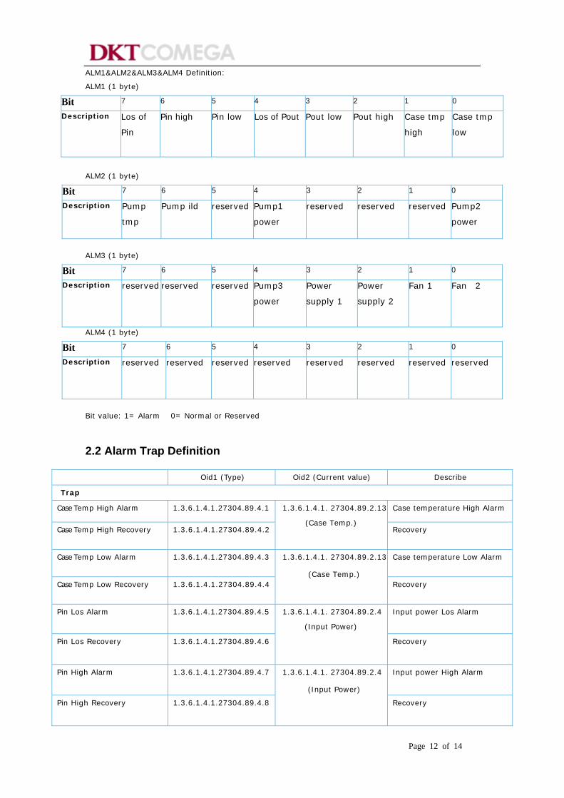
ALM1&ALM2&ALM3&ALM4 Definition:
ALM1 (1 byte)
Bit 7 6 5 4 3 2 1 0 Description Los of
Pin Pin high Pin low Los of Pout Pout low Pout high Case tmp
high Case tmp
low
ALM2 (1 byte)
Bit 7 6 5 4 3 2 1 0 Description Pump
tmp Pump ild reserved Pump1
power reserved reserved reserved Pump2
power
ALM3 (1 byte)
Bit 7 6 5 4 3 2 1 0 Description reserved reserved reserved Pump3
power Power
supply 1 Power
supply 2 Fan 1 Fan 2
ALM4 (1 byte)
Bit 7 6 5 4 3 2 1 0 Description reserved reserved reserved reserved reserved reserved reserved reserved
Bit value: 1= Alarm 0= Normal or Reserved
2.2 Alarm Trap Definition
Oid1 (Type) Oid2 (Current value) Describe Trap Case Temp High Alarm 1.3.6.1.4.1.27304.89.4.1 Case temperature High Alarm
Case Temp High Recovery 1.3.6.1.4.1.27304.89.4.2
1.3.6.1.4.1. 27304.89.2.13
(Case Temp.) Recovery
Case Temp Low Alarm 1.3.6.1.4.1.27304.89.4.3 Case temperature Low Alarm
Case Temp Low Recovery 1.3.6.1.4.1.27304.89.4.4
1.3.6.1.4.1. 27304.89.2.13
(Case Temp.) Recovery
Pin Los Alarm 1.3.6.1.4.1.27304.89.4.5 Input power Los Alarm
Pin Los Recovery 1.3.6.1.4.1.27304.89.4.6
1.3.6.1.4.1. 27304.89.2.4
(Input Power) Recovery
Pin High Alarm 1.3.6.1.4.1.27304.89.4.7 Input power High Alarm
Pin High Recovery 1.3.6.1.4.1.27304.89.4.8
1.3.6.1.4.1. 27304.89.2.4
(Input Power) Recovery
Page 13 of 14
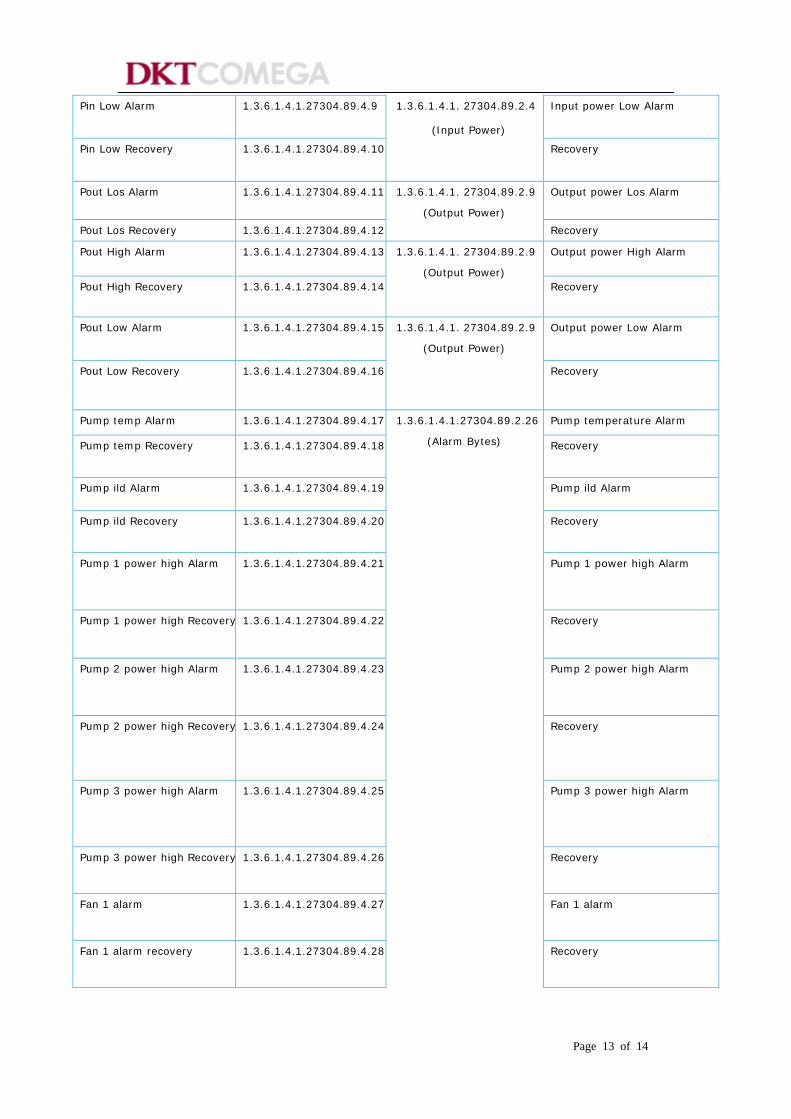
Pin Low Alarm 1.3.6.1.4.1.27304.89.4.9 Input power Low Alarm
Pin Low Recovery 1.3.6.1.4.1.27304.89.4.10
1.3.6.1.4.1. 27304.89.2.4
(Input Power) Recovery
Pout Los Alarm 1.3.6.1.4.1.27304.89.4.11 Output power Los Alarm
Pout Los Recovery 1.3.6.1.4.1.27304.89.4.12
1.3.6.1.4.1. 27304.89.2.9
(Output Power) Recovery
Pout High Alarm 1.3.6.1.4.1.27304.89.4.13 Output power High Alarm
Pout High Recovery 1.3.6.1.4.1.27304.89.4.14
1.3.6.1.4.1. 27304.89.2.9
(Output Power) Recovery
Pout Low Alarm 1.3.6.1.4.1.27304.89.4.15 Output power Low Alarm
Pout Low Recovery 1.3.6.1.4.1.27304.89.4.16
1.3.6.1.4.1. 27304.89.2.9
(Output Power) Recovery
Pump temp Alarm 1.3.6.1.4.1.27304.89.4.17 Pump temperature Alarm Pump temp Recovery 1.3.6.1.4.1.27304.89.4.18
1.3.6.1.4.1.27304.89.2.26
(Alarm Bytes)
Recovery
Pump ild Alarm 1.3.6.1.4.1.27304.89.4.19 Pump ild Alarm
Pump ild Recovery 1.3.6.1.4.1.27304.89.4.20
Recovery
Pump 1 power high Alarm 1.3.6.1.4.1.27304.89.4.21
Pump 1 power high Alarm
Pump 1 power high Recovery 1.3.6.1.4.1.27304.89.4.22
Recovery
Pump 2 power high Alarm 1.3.6.1.4.1.27304.89.4.23
Pump 2 power high Alarm
Pump 2 power high Recovery 1.3.6.1.4.1.27304.89.4.24
Recovery
Pump 3 power high Alarm 1.3.6.1.4.1.27304.89.4.25
Pump 3 power high Alarm
Pump 3 power high Recovery 1.3.6.1.4.1.27304.89.4.26 Recovery
Fan 1 alarm 1.3.6.1.4.1.27304.89.4.27 Fan 1 alarm
Fan 1 alarm recovery 1.3.6.1.4.1.27304.89.4.28 Recovery

Page 14 of 14
Fan 2 alarm 1.3.6.1.4.1.27304.89.4.29 Fan 2 alarm
Fan 2 alarm recovery 1.3.6.1.4.1.27304.89.4.30 Recovery
Power Supply 1 alarm 1.3.6.1.4.1.27304.89.4.31 Power supply 1 alarm
Power Supply 1 alarm recovery
1.3.6.1.4.1.27304.89.4.32 Recovery
Power Supply 2 alarm 1.3.6.1.4.1.27304.89.4.33 Power supply 2 alarm
Power Supply 2 alarm recovery
1.3.6.1.4.1.27304.89.4.34 Recovery
(END)