d.j. schlossberg, d.j. battaglia, m.w. bongard, r.j....
TRANSCRIPT

D.J. Schlossberg, D.J. Battaglia, M.W. Bongard, R.J. Fonck, A.J. Redd
D.J. Schlossberg, 51st APS – Division of Plasma Physics Meeting, Atlanta, GA Nov 2-6, 2009
University of Wisconsin - Madison 1500 Engineering Drive
Madison, WI 53706

Work supported by U.S. DOE Grant DE-FG02-96ER54375
• Non-solenoidal startup using point-source DC helicity injectors (plasma guns) has been achieved in the PEGASUS Toroidal Experiment for plasmas with Ip in excess of 100 kA using Iinj < 4 kA.
• Maximum achieved Ip tentatively scales as (ITFIinj/w)1/2
• Ip limits conform to a simple model involving helicity conservation and Taylor relaxation
• Observed MHD activity reveals additional dynamics during the relaxation process
• Recent upgrades to the gun system provide: - Higher helicity injection rates - Smaller edge current width, w
• Future goals include: - Extending parametric scaling studies - Determining conditions where parallel conduction losses dominate helicity dissipation - Building the physics understanding of helicity injection to confidently design gun systems for
larger, future tokamaks.
D.J. Schlossberg, 51st APS – Division of Plasma Physics Meeting, Atlanta, GA Nov 2-6, 2009

D.J. Schlossberg, 51st APS – Division of Plasma Physics Meeting, Atlanta, GA Nov 2-6, 2009
• Solenoid-free startup and ramp-up have been identified by FESAC as critical ST issues (FESAC TAP report)
• Solenoid-free startup with point-source helicity injection significantly extends the PEGASUS operating space – Saves limited Ohmic transformer flux – May enable high-IN, high-β studies on PEGASUS
• Point-source helicity injection is flexible – Gun assemblies can be placed at convenient locations – Presently being studied on PEGASUS (to date: Ip up to 0.17 MA)

D.J. Schlossberg, 51st APS – Division of Plasma Physics Meeting, Atlanta, GA Nov 2-6, 2009
Ohmic Trim Coils
RF HeatingAnntenna
VacuumVessel
Centerstack:Exposing Ohmic HeatingSolenoid (NHMFL)
Equilibrium FieldCoils
PlasmaLimiters
Toroidal FieldCoils
• Non-inductive startup and sustainment • Tokamak physics in small aspect ratio:
- High-IN, high-β operating regimes - ELM-like edge MHD activity
(see poster by E.T. Hinson, this session)
Experimental Parameters Parameter A R(m) Ip (MA) IN (MA/m-T) RBt (T-m) κ τshot (s) βt (%) PHHFW (MW)
Achieved 1.15 – 1.3 0.2 – 0.45 ≤ .21
6 – 12 ≤ 0.06
1.4 – 3.7 ≤ 0.025 ≤ 25 0.2
Goals 1.12 – 1.3 0.2 – 0.45 ≤ 0.30 6 – 20 ≤ 0.1
1.4 – 3.7 ≤ 0.05 > 40 1.0
D.J. Schlossberg, 51st APS – Division of Plasma Physics Meeting, Atlanta, GA Nov 2-6, 2009
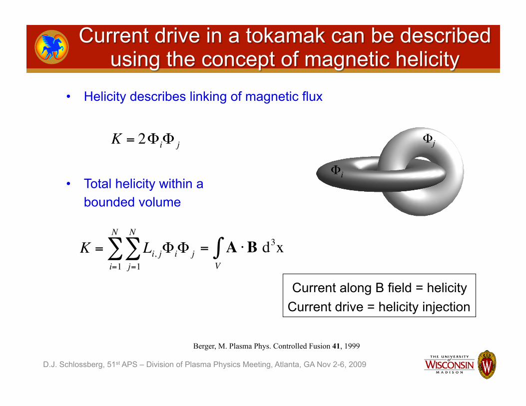
• Helicity describes linking of magnetic flux
• Total helicity within a bounded volume €
K = 2ΦiΦ j
Φi
Φj
€
= AV∫ ⋅B d3x
€
K = Li, jΦiΦ jj=1
N
∑i=1
N
∑
Berger, M. Plasma Phys. Controlled Fusion 41, 1999
Current along B field = helicity Current drive = helicity injection

D.J. Schlossberg, 51st APS – Division of Plasma Physics Meeting, Atlanta, GA Nov 2-6, 2009
€
dKdt
= − 2 ηJ ⋅B d3xV∫ − 2∂ψ
∂tΨ − 2 ΦB ⋅ ds
A∫
• Resistive Helicity Dissipation – E = ηJ → much slower than energy dissipation (ηJ2) – Turbulent relaxation processes dissipate energy and conserve helicity
• AC Helicity Injection:
• DC Helicity Injection: €
K•
AC = −2∂ψ∂t
Ψ = 2VloopΨ
€
K•
DC = −2 ΦBA∫ ⋅ ds = 2VinjB⊥Ainj
€
K = A +A vac( )V∫ ⋅ B −Bvac( ) d3xTotal helicity in a tokamak geometry:
D.J. Schlossberg, 51st APS – Division of Plasma Physics Meeting, Atlanta, GA Nov 2-6, 2009
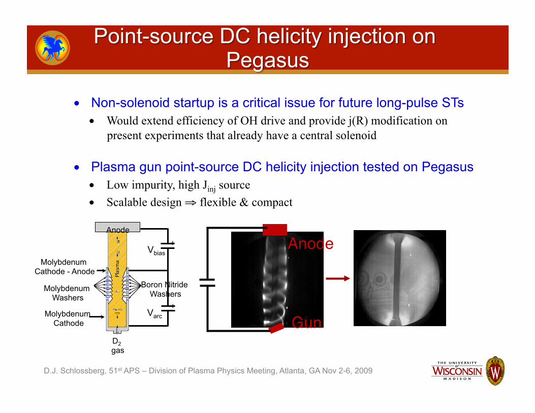
• Non-solenoid startup is a critical issue for future long-pulse STs • Would extend efficiency of OH drive and provide j(R) modification on
present experiments that already have a central solenoid
• Plasma gun point-source DC helicity injection tested on Pegasus • Low impurity, high Jinj source • Scalable design ⇒ flexible & compact
Anode
Gun Molybdenum Cathode
Molybdenum Cathode - Anode
Boron Nitride Washers
Molybdenum Washers
Anode
D2 gas
Vbias +
Varc +
D.J. Schlossberg, 51st APS – Division of Plasma Physics Meeting, Atlanta, GA Nov 2-6, 2009
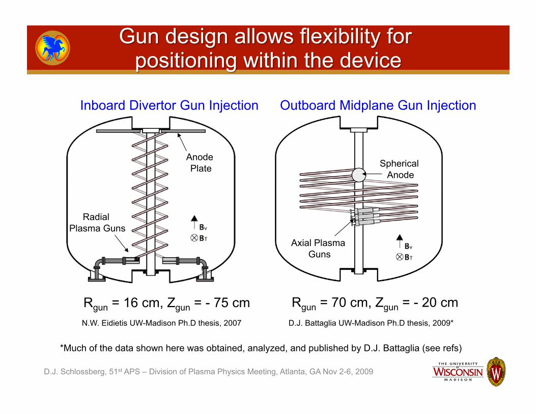
Inboard Divertor Gun Injection Outboard Midplane Gun Injection
Anode Plate
Radial Plasma Guns
Axial Plasma Guns
Spherical Anode
Rgun = 16 cm, Zgun = - 75 cm Rgun = 70 cm, Zgun = - 20 cm N.W. Eidietis UW-Madison Ph.D thesis, 2007 D.J. Battaglia UW-Madison Ph.D thesis, 2009*
*Much of the data shown here was obtained, analyzed, and published by D.J. Battaglia (see refs)
D.J. Schlossberg, 51st APS – Division of Plasma Physics Meeting, Atlanta, GA Nov 2-6, 2009
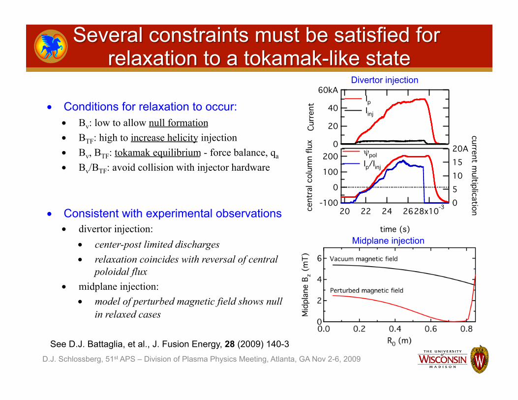
• Conditions for relaxation to occur: • Bv: low to allow null formation • BTF: high to increase helicity injection • Bv, BTF: tokamak equilibrium - force balance, qa • Bv/BTF: avoid collision with injector hardware
• Consistent with experimental observations • divertor injection:
• center-post limited discharges • relaxation coincides with reversal of central
poloidal flux • midplane injection:
• model of perturbed magnetic field shows null in relaxed cases
60kA
40
20
0
Curr
ent
28x10-326242220
time (s)
200
100
0
-100cent
ral c
olum
n flu
x
20A151050
current multiplication
Ip Iinj
ψpol Ip/Iinj
Divertor injection
Midplane injection
See D.J. Battaglia, et al., J. Fusion Energy, 28 (2009) 140-3

D.J. Schlossberg, 51st APS – Division of Plasma Physics Meeting, Atlanta, GA Nov 2-6, 2009
€
M ≡ Iφ /IinjCurrent multiplication:
Open field line current M = G
Injected current perturbs vacuum magnetic field
Tokamak-like plasma M > G
Plasma expands inwards to fill the volume while connected to
guns
Limits dictated by helicity and Taylor relaxation
Decaying plasma
Stochastic magnetic fields “heal” into closed
magnetic surfaces
D.J. Schlossberg, 51st APS – Division of Plasma Physics Meeting, Atlanta, GA Nov 2-6, 2009
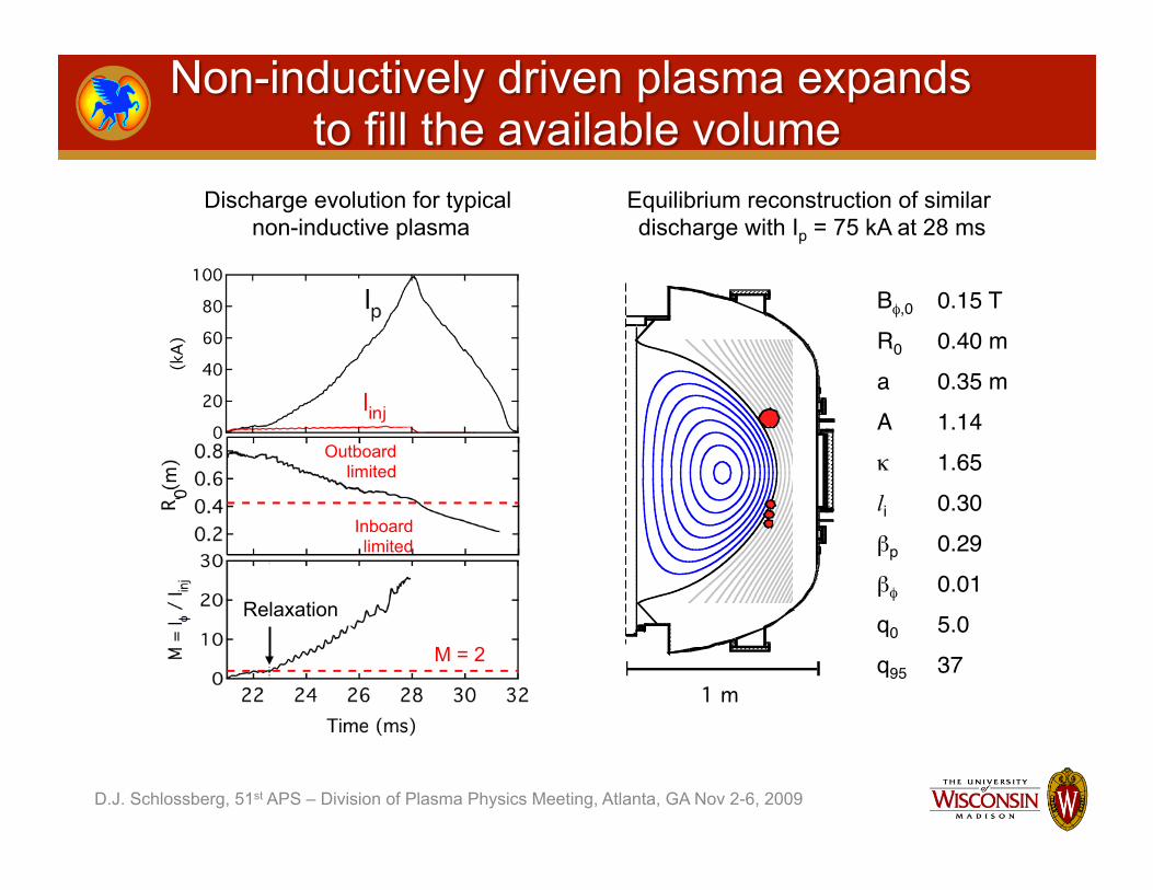
Equilibrium reconstruction of similar discharge with Ip = 75 kA at 28 ms
1 m
Bφ,0 0.15 T R0 0.40 m a 0.35 m A 1.14 κ 1.65 li 0.30 βp 0.29 βφ 0.01 q0 5.0 q95 37 M = 2
Relaxation
Outboard limited
Inboard limited
0 Discharge evolution for typical
non-inductive plasma

D.J. Schlossberg, 51st APS – Division of Plasma Physics Meeting, Atlanta, GA Nov 2-6, 2009
Helicity balance in a tokamak geometry:
€
dKdt
= − 2 ηJ ⋅B d3xV∫ − 2∂ψ
∂tΨ − 2 ΦB ⋅ ds
A∫
€
Ip ≤Ap
2πR0 ηVind +Veff( )
• Assumes system is in steady-state (dK/dt = 0) • Ip limit depends on the scaling of plasma confinement via the η term
€
Veff ≈NinjAinjBφ ,inj
ΨVbias
Taylor relaxation of a force-free equilibrium:
€
∇ × B = µ0J = λB
€
λp ≤ λedge
€
µ0IpΨ≤ µ0Iinj2πRinjwBθ ,inj
Assumptions: • Driven edge current mixes uniformly in SOL • Edge fields average to tokamak-like structure
Ap Plasma area fG Plasma geometric factor ITF Toroidal field current w Edge width €
Ip ≤ fGεApITFIinj2πRinjw
1/ 2
D.J. Schlossberg, 51st APS – Division of Plasma Physics Meeting, Atlanta, GA Nov 2-6, 2009
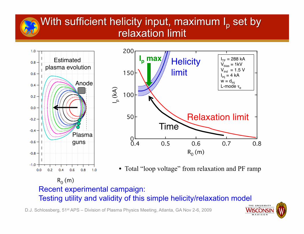
Estimated plasma evolution
Plasma guns
Anode
Relaxation limit
Helicity limit
Ip max
Time
ITF = 288 kA Vbias = 1kV Vind = 1.5 V Iinj = 4 kA w = dinj L-mode τe
• Total “loop voltage” from relaxation and PF ramp
Recent experimental campaign: Testing utility and validity of this simple helicity/relaxation model
D.J. Schlossberg, 51st APS – Division of Plasma Physics Meeting, Atlanta, GA Nov 2-6, 2009
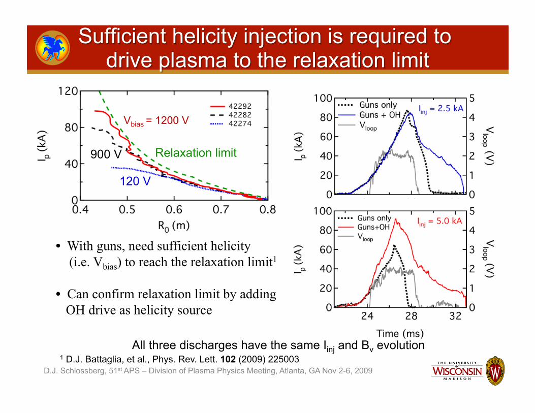
All three discharges have the same Iinj and Bv evolution
120 V
900 V
Vbias = 1200 V
Relaxation limit
• With guns, need sufficient helicity (i.e. Vbias) to reach the relaxation limit1
• Can confirm relaxation limit by adding OH drive as helicity source
1 D.J. Battaglia, et al., Phys. Rev. Lett. 102 (2009) 225003

D.J. Schlossberg, 51st APS – Division of Plasma Physics Meeting, Atlanta, GA Nov 2-6, 2009
€
∝ Iinj
€
Ip ≤ fGεApITFIinj2πRinjw
1/ 2
• At each R0, max. Ip achieved scales as Iinj
1/2
• Kinj insufficient to drive some discharges to limit as plasma expands
• Scan Iinj: 1 - 5 kA – ITF = 288 kA – 3 plasma guns: defines w – Assume plasma geometry (thus, εAp/Redge) fixed at given R0
D.J. Schlossberg, 51st APS – Division of Plasma Physics Meeting, Atlanta, GA Nov 2-6, 2009
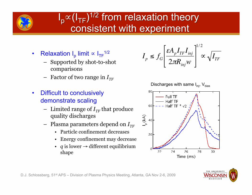
• Relaxation Ip limit ∝ ITF1/2
– Supported by shot-to-shot comparisons
– Factor of two range in ITF
• Difficult to conclusively demonstrate scaling
– Limited range of ITF that produce quality discharges
– Plasma parameters depend on ITF • Particle confinement decreases • Energy confinement may decrease • q is lower → different equilibrium
shape
Discharges with same Iinj, Vbias €
∝ ITF
€
Ip ≤ fGεApITFIinj2πRinjw
1/ 2

D.J. Schlossberg, 51st APS – Division of Plasma Physics Meeting, Atlanta, GA Nov 2-6, 2009
Anode
3 guns
w
• Relaxation limit predicted to scale as w-1/2 • Data suggests w ∝ NgunDgun
– Likely due to alignment of plasma guns with flux surfaces – w may also be related to edge instabilities, turbulence, drifts, etc.
€
∝1w
€
Ip ≤ fGεApITFIinj2πRinjw
1/ 2

• Orientation of gun array matched to edge field alignment – Re-orientation is equivalent to a reduction in current channel width – Experiments show increased relaxation limit
D.J. Schlossberg, 51st APS – Division of Plasma Physics Meeting, Atlanta, GA Nov 2-6, 2009
Anode
3 guns
w
140
120
100
80
60
40
20
0
kA
0.80.70.60.50.4m
After alignment Before alignment
D.J. Schlossberg, 51st APS – Division of Plasma Physics Meeting, Atlanta, GA Nov 2-6, 2009
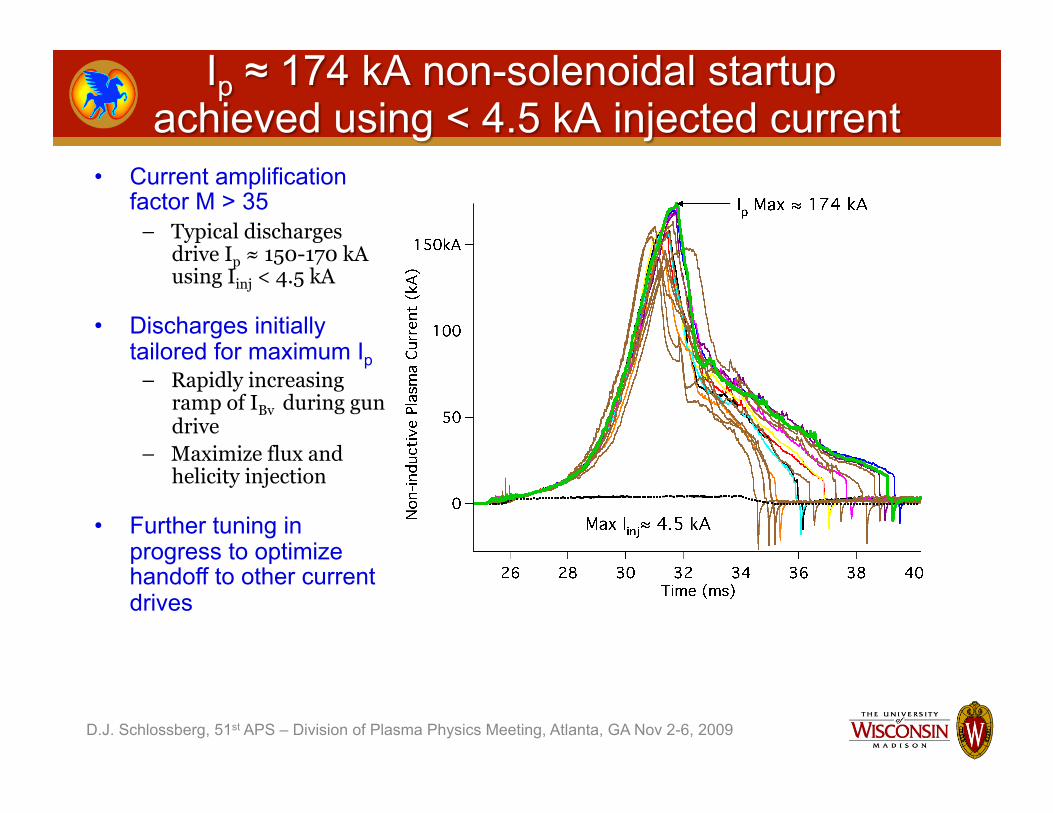
• Current amplification factor M > 35
– Typical discharges drive Ip ≈ 150-170 kA using Iinj < 4.5 kA
• Discharges initially tailored for maximum Ip
– Rapidly increasing ramp of IBv during gun drive
– Maximize flux and helicity injection
• Further tuning in progress to optimize handoff to other current drives

D.J. Schlossberg, 51st APS – Division of Plasma Physics Meeting, Atlanta, GA Nov 2-6, 2009
• 80 kA target handoff to OH drive
– Best coupling achieved when OH drive applied shortly after gun turnoff
• 150 kA with 18 mV-s – ~ 50% flux savings
• Extending operation space - No significant MHD during
Ohmic phase - Unlike OH only, where large
scale n=1 activity limits plasma evolution
- Equilibrium reconstruction of gun created plasmas show very low li ~ 0.2-0.3, and hollow J(r)

D.J. Schlossberg, 51st APS – Division of Plasma Physics Meeting, Atlanta, GA Nov 2-6, 2009
Slower PF ramp Plasma detaches at 29.4 ms
Faster PF ramp Plasma detaches at 25.3 ms
After detachment, current drive is purely inductive and MHD activity is reduced.
Est
imat
ed
Est
imat
ed

• What determines λedge and λp? • Edge current measurements with probes • Larger range of ITF to test scaling • Re-tilted guns
• How does τe scale with Ip? • Thomson scattering • Increase Vbias to achieve larger Ip
• What determines Zinj? • Filament path length and modeling
• Tokamak-like plasma properties: Ti, Te • Spectrometer, Thomson scattering
D.J. Schlossberg, 51st APS – Division of Plasma Physics Meeting, Atlanta, GA Nov 2-6, 2009

D.J. Schlossberg, 51st APS – Division of Plasma Physics Meeting, Atlanta, GA Nov 2-6, 2009
• Proposed improvements to power systems will: – Increase ITF by factor of 2 – Increase Iinj by at least a factor of 2
• Repositioning gun hardware will increase available Ap
– Increasing Rinj will enlarge Ap by factor of ~1.7
• Additional upgrades: – Increase ITF further by upgrading our center stack – Optimize λedge by introduction
of passive electrode structures – Push limits of gun performance by
increasing Iinj
€
Ip ≤ fGεApITFIinj2πRinjw
1/ 2
year
I p (M
A)
0.0
0.1
0.2
2007 2008 2009 2010
single gun
three guns increased
TF, Vbias
0.3
new geometry larger guns
(Proposed)
• Outboard midplane gun startup results show great promise
• Ip ~ 0.17 MA achieved with simple 3-gun array and PF induction
• Helicity & Relaxation limits being identified to guide design to higher current - Simple dc relaxation-helicity conservation model describes
macroscopic scaling of current limit - Many outstanding questions: λedge, Zinj, confinement, etc - Full understanding at microscopic level (e.g.. Intermittent MHD) will
require deeper analysis (i.e. NIMROD)
• Pegasus goal: ~0.3 MA non-solenoidal target & hand-off to RF heating & growth - Allows validation of understanding for projection to larger facilities
(e.g.. NSTX up to MA)
D.J. Schlossberg, 51st APS – Division of Plasma Physics Meeting, Atlanta, GA Nov 2-6, 2009
For additional information, see: - Non-solenoidal tokamak startup using outboard plasma gun current injection
D.J. Battaglia, M.W. Bongard, R.J. Fonck, A.J. Redd. Nucl. Fus., in preparation. - High-current tokamak startup using point-source DC helicity injection
D.J. Battaglia, M.W. Bongard, R.J. Fonck, A.J. Redd, A.C. Sontag, Phys. Rev. Lett. 102 (2009) 225003.
-The formation of a tokamak-like plasma in initial experiments using an outboard plasma gun current source D.J. Battaglia, M.W. Bongard, R.J. Fonck, A.J. Redd, A.C. Sontag, J. Fusion Energy, 28 (2009) 140-3. Bayliss, Sovinec, and Redd, “MHD simulations of CHI with weak relaxation in the HIT-II
spherical tokamak,” in preparation. Redd et al., Journal of Fusion Energy DOI 10.1007/s10894-008-9183-9 (Nov 2008). Battaglia et al., Journal of Fusion Energy, in press (2008). Garstka et al., Journal of Fusion Energy 27, 20-24 (2008). Redd et al., Physics of Plasmas 14, 112511 (2007). Unterberg et al., Journal of Fusion Energy 26, 221-225 (2007). Eidietis et al., Journal of Fusion Energy 26, 43-46 (2007). Garstka et al., Nuclear Fusion 46, S603 (2006). Tang and Boozer, Physics of Plasmas 12, 102102 (2005). Garstka et al., Physics of Plasmas 10, 1705 (2003).

If you would like an electronic copy of this poster, please leave your name and e-mail address below:
D.J. Schlossberg, 51st APS – Division of Plasma Physics Meeting, Atlanta, GA Nov 2-6, 2009