diy camera monitor · overview in this project, we're going to make a diy monitor using an...
TRANSCRIPT
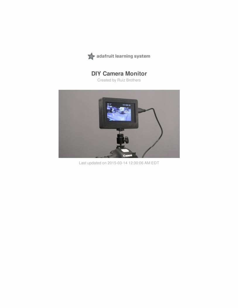
DIY Camera MonitorCreated by Ruiz Brothers
Last updated on 2015-03-14 12:30:06 AM EDT

2344
556
7778
99
10101112121213141415161616171818191920212223
Guide Contents
Guide ContentsOverview
PartsTools & Supplies
Circuit DiagramWired ConenctionsPowering with USB only
3D PrintingNo 3D printer? 3D Printing ServicesPLA FilamentSlicing Software
AssemblyBattery holder cablesDesolderwires from battery holderTin wires and slide switchSlide Switch ConnectionSolder UBECUBEC JST ConnectorThread UBEC Wiring through back coverMount battery holder to back coverAssembled Cover and Battery HolderPrepare display backpackOpen -25mA for dimmingBreak the TraceSecond Slide SwitchSolder dim switchMount Display Backpack to EnclosureWire JST to Display BackpackInstall Slide Switches into EnclosurePackage wiring and componentsClosing up enclosureMount back coverInstall tripod adapterTest it, Display it!DIY 3D Printed HDMI Monitor
© Adafruit Industries https://learn.adafruit.com/diy-camera-monitor Page 2 of 23
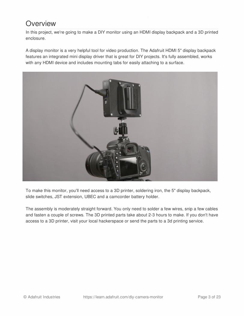
OverviewIn this project, we're going to make a DIY monitor using an HDMI display backpack and a 3D printedenclosure.
A display monitor is a very helpful tool for video production. The Adafruit HDMI 5" display backpackfeatures an integrated mini display driver that is great for DIY projects. It's fully assembled, workswith any HDMI device and includes mounting tabs for easily attaching to a surface.
To make this monitor, you'll need access to a 3D printer, soldering iron, the 5" display backpack,slide switches, JST extension, UBEC and a camcorder battery holder.
The assembly is moderately straight forward. You only need to solder a few wires, snip a few cablesand fasten a couple of screws. The 3D printed parts take about 2-3 hours to make. If you don't haveaccess to a 3D printer, visit your local hackerspace or send the parts to a 3d printing service.
© Adafruit Industries https://learn.adafruit.com/diy-camera-monitor Page 3 of 23

Parts
We have all the lovely components and tools to build this project. Be sure to check out the featuredproducts on the right sidebar.
HDMI 5" Display Backpack (http://adafru.it/2232)2X SPDT Slide Switch (http://adafru.it/drN)UBEC DC/DC Step-Down (http://adafru.it/efD)JST Extension (http://adafru.it/doS)Camcorder Battery Holder (http://adafru.it/efE)1/4" to 3/8" Convert Screw Adapter for Tripod (http://adafru.it/efF)1/4" Mount Adapter To Video Camcorder Hot Shoe (http://adafru.it/efG)Phillip Flat Head #4-40 x 3/8 (http://adafru.it/eIL)
Tools & Supplies
You'll need a couple of hand tools and accessories to assist you in the build.
Solder Iron (http://adafru.it/1204) + Solder (http://adafru.it/734)Silicone Wire (http://adafru.it/1877)PLA Filament (http://adafru.it/dtp)3D Printer (http://adafru.it/duF)
© Adafruit Industries https://learn.adafruit.com/diy-camera-monitor Page 4 of 23

Circuit Diagram
Wired Conenctions
Follow the circuit diagram above to reference the connections for each component. The parts arenot to scale but should give you a visual idea of the circuit.
Battery HolderPositive > UBEC PositiveNegative > UBEC Negative
HDMI BackpackGND > UBEC negative+5V USB > UBEC postive
The positive wire on the battery is connected to the slide switch and postive wire on the UBEC (fromthe short wires). The short negative wire from the ubec is connected to the negative wire on thebattery holder.
The +5V and GND pads next to USB port are connected to a female JST cable. A slide switch isconnected to the -25mA pad on the HDMI display backpack.
© Adafruit Industries https://learn.adafruit.com/diy-camera-monitor Page 5 of 23

Powering with USB only
Optionally plug in a micro USB cable to the HDMI display backpack to power from a batterybank orwall outlet using a USB adapter.
You can optionally convert the UBEC into a microUSB cable using an DIY connectorplug (http://adafru.it/1390). Look up the pinouts for wiring and be careful to get it right!
Cut the 'Open for -25mA' jumper before soldering connection to slide switch.
© Adafruit Industries https://learn.adafruit.com/diy-camera-monitor Page 6 of 23
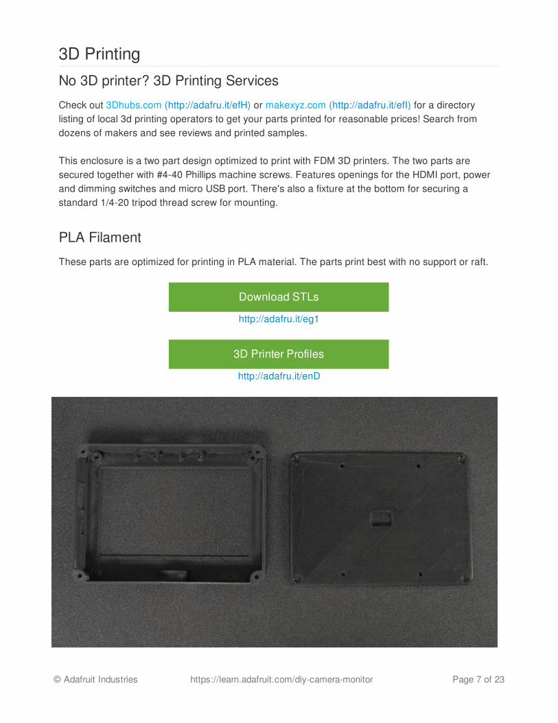
3D PrintingNo 3D printer? 3D Printing Services
Check out 3Dhubs.com (http://adafru.it/efH) or makexyz.com (http://adafru.it/efI) for a directorylisting of local 3d printing operators to get your parts printed for reasonable prices! Search fromdozens of makers and see reviews and printed samples.
This enclosure is a two part design optimized to print with FDM 3D printers. The two parts aresecured together with #4-40 Phillips machine screws. Features openings for the HDMI port, powerand dimming switches and micro USB port. There's also a fixture at the bottom for securing astandard 1/4-20 tripod thread screw for mounting.
PLA Filament
These parts are optimized for printing in PLA material. The parts print best with no support or raft.
Download STLs
http://adafru.it/eg1
3D Printer Profiles
http://adafru.it/enD
© Adafruit Industries https://learn.adafruit.com/diy-camera-monitor Page 7 of 23
Slicing Software
The recommend settings above should work with most slicing software. However, you areencouraged to use your own settings since 3D printers and slicing software will vary from printer toprinter.
displayCase.stl
displayBack.stl
@235 PLA10% Infill0.2 Layer Height2 Shells90/120 Feed / Travel Speeds
about 2 hours to print.
© Adafruit Industries https://learn.adafruit.com/diy-camera-monitor Page 8 of 23
Assembly
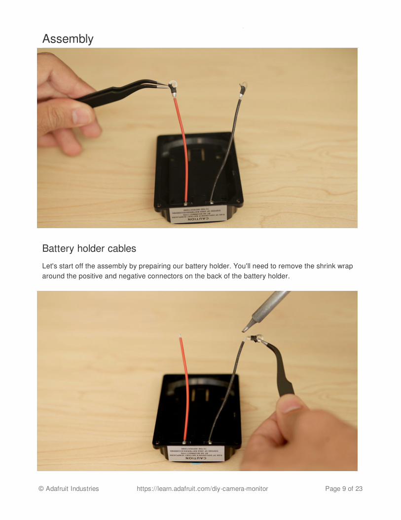
Battery holder cables
Let's start off the assembly by prepairing our battery holder. You'll need to remove the shrink wraparound the positive and negative connectors on the back of the battery holder.
© Adafruit Industries https://learn.adafruit.com/diy-camera-monitor Page 9 of 23

Desolderwires from battery holder
The battery holder includes hoop connectors. We need to cut or unsolder the hoops that areattached to the wires.
Tin wires and slide switch
Next up we need to wire the slide switch to the battery holder. Prepare a slide switch by tinning twoterminals. Measure two pieces of heat shrink tubing (http://adafru.it/1649)and add them to thepostive red wire before soldering to the slide switch.
© Adafruit Industries https://learn.adafruit.com/diy-camera-monitor Page 10 of 23
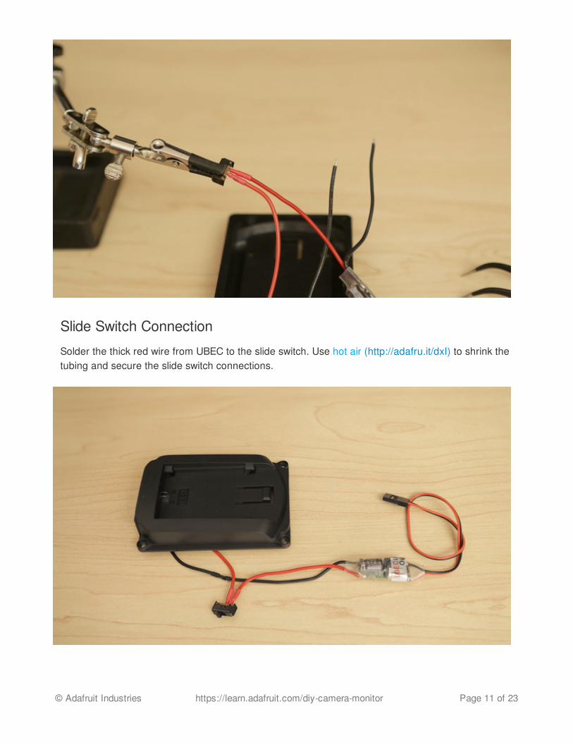
Slide Switch Connection
Solder the thick red wire from UBEC to the slide switch. Use hot air (http://adafru.it/dxI) to shrink thetubing and secure the slide switch connections.
© Adafruit Industries https://learn.adafruit.com/diy-camera-monitor Page 11 of 23
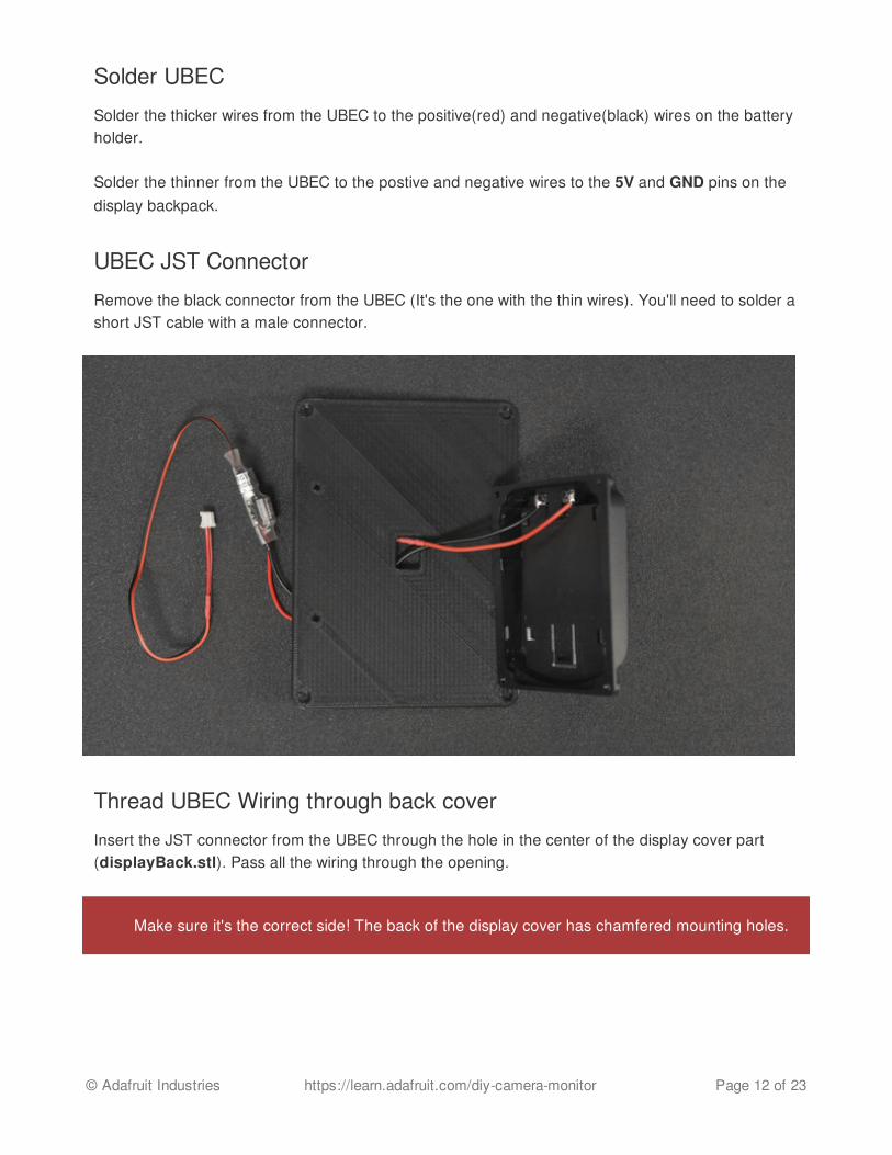
Solder UBEC
Solder the thicker wires from the UBEC to the positive(red) and negative(black) wires on the batteryholder.
Solder the thinner from the UBEC to the postive and negative wires to the 5V and GND pins on thedisplay backpack.
UBEC JST Connector
Remove the black connector from the UBEC (It's the one with the thin wires). You'll need to solder ashort JST cable with a male connector.
Thread UBEC Wiring through back cover
Insert the JST connector from the UBEC through the hole in the center of the display cover part(displayBack.stl). Pass all the wiring through the opening.
Make sure it's the correct side! The back of the display cover has chamfered mounting holes.
© Adafruit Industries https://learn.adafruit.com/diy-camera-monitor Page 12 of 23

Mount battery holder to back cover
Position and orient the battery holder over the cover so the mounting holes line up. Use four #4-40phillips screws to secure the battery holder to the back cover.
© Adafruit Industries https://learn.adafruit.com/diy-camera-monitor Page 13 of 23

Assembled Cover and Battery Holder
Check point. Ensure the wiring is long enough to reach the display backpack. The slide switchshould be able to reach the opening in the enclosure.
Prepare display backpack
Use a panavise to securely hold the backpack while soldering.
© Adafruit Industries https://learn.adafruit.com/diy-camera-monitor Page 14 of 23

Open -25mA for dimming
In this project we want the dimming feature so we need to break a trace on the display backpack toenable it.
© Adafruit Industries https://learn.adafruit.com/diy-camera-monitor Page 15 of 23
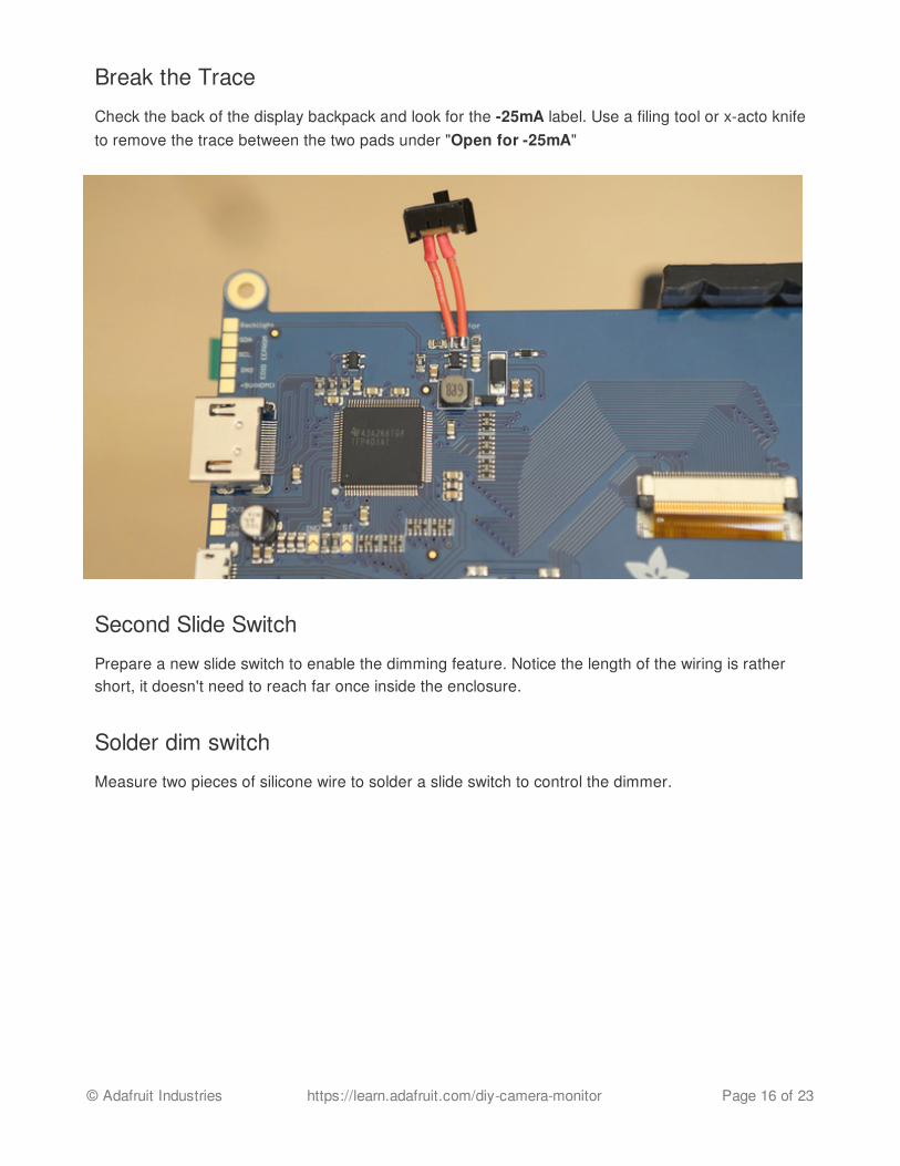
Break the Trace
Check the back of the display backpack and look for the -25mA label. Use a filing tool or x-acto knifeto remove the trace between the two pads under "Open for -25mA"
Second Slide Switch
Prepare a new slide switch to enable the dimming feature. Notice the length of the wiring is rathershort, it doesn't need to reach far once inside the enclosure.
Solder dim switch
Measure two pieces of silicone wire to solder a slide switch to control the dimmer.
© Adafruit Industries https://learn.adafruit.com/diy-camera-monitor Page 16 of 23
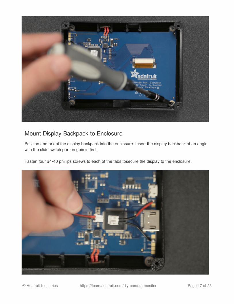
Mount Display Backpack to Enclosure
Position and orient the display backpack into the enclosure. Insert the display backback at an anglewith the slide switch portion goin in first.
Fasten four #4-40 phillips screws to each of the tabs tosecure the display to the enclosure.
© Adafruit Industries https://learn.adafruit.com/diy-camera-monitor Page 17 of 23
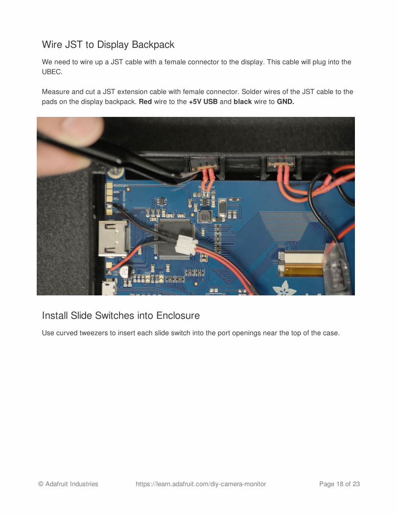
Wire JST to Display Backpack
We need to wire up a JST cable with a female connector to the display. This cable will plug into theUBEC.
Measure and cut a JST extension cable with female connector. Solder wires of the JST cable to thepads on the display backpack. Red wire to the +5V USB and black wire to GND.
Install Slide Switches into Enclosure
Use curved tweezers to insert each slide switch into the port openings near the top of the case.
© Adafruit Industries https://learn.adafruit.com/diy-camera-monitor Page 18 of 23

Package wiring and components
Arrange the wire connections to the sides of the case, away from the pads and slide switches.
Closing up enclosure
© Adafruit Industries https://learn.adafruit.com/diy-camera-monitor Page 19 of 23

Ensure the UBEC and wired connections are fitted into the enclosure.
Mount back cover
Position and orient the back cover over the enclosure. Line up the mounting holes and fasten four#4-40 phillips screws to each mounting hole to secure the cover to the enclosure.
© Adafruit Industries https://learn.adafruit.com/diy-camera-monitor Page 20 of 23

Install tripod adapter
The bottom of the enclosure features a mounting hole for a standard tripod adapter.
Place the tripod thread into the opening and install it by using a flat head screwdriver to fasten the1/4" to 3/8" convert screw into the bottom of the case.
The tolerance should have a tight fit. Use adhesives for a permanent installation.
© Adafruit Industries https://learn.adafruit.com/diy-camera-monitor Page 21 of 23
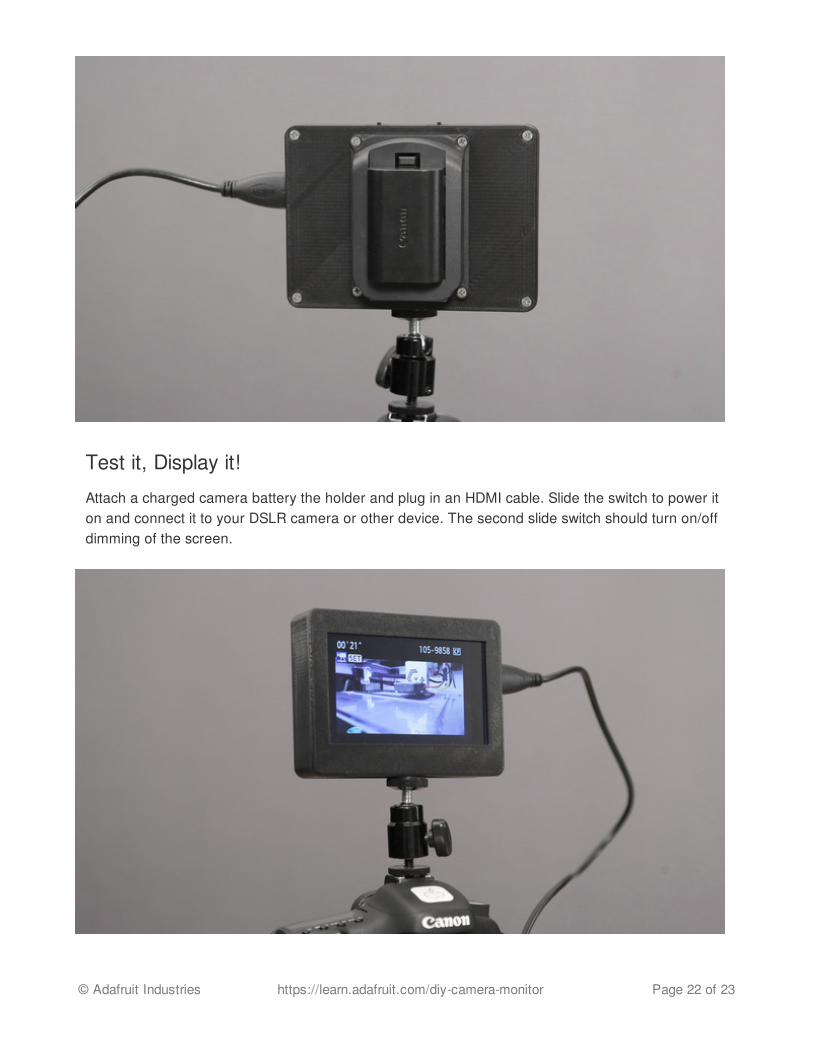
Test it, Display it!
Attach a charged camera battery the holder and plug in an HDMI cable. Slide the switch to power iton and connect it to your DSLR camera or other device. The second slide switch should turn on/offdimming of the screen.
© Adafruit Industries https://learn.adafruit.com/diy-camera-monitor Page 22 of 23
DIY 3D Printed HDMI Monitor
This is really nice, low-cost display perfect for DIY projects like monitoring arial drone shots, mobilegaming, and of course video production and photography.
© Adafruit Industries Last Updated: 2015-03-14 12:30:07 AM EDT Page 23 of 23