generaldnhiggins.com/docs/606 division 3 - concrete.pdf · 2013-11-20 · aci 117, standard...
TRANSCRIPT
Spec. Standard: 10/30/13 03050-1 Revision: 10/2/13
SECTION 03050 CONCRETE ADMIXTURE WATERPROOFING
GENERAL PART 1 -
SCOPE: 1.01
A. Summary of Work: The WORK of this SECTION specifies crystalline waterproofing admixture for use with new concrete, cast-in-place concrete and/or self-consolidating concrete (SCC) required by the Contract Documents.
B. Related Work Specified Elsewhere:
1. SECTION 01300 – Submittals
2. SECTION 03312 - Self-Consolidating Concrete (SCC)
3. SECTION 03300 - Cast-In-Place Concrete
4. SECTION 03600 - Grout
APPLICABLE STANDARDS AND PUBLICATIONS: 1.02
A. Standards or Codes: The edition of the standards of the organizations listed below in effect at the time of the advertisement for bids form a part of this specification to the extent referenced. See the various paragraphs for the specified standard. In the case of a conflict between the requirements of this SECTION and those of the listed document, the requirements of this SECTION shall prevail.
1. American Concrete Institute (ACI)
a. ACI 117 – Specification for Tolerances for Concrete Construction and Materials
b. ACI 212.3R – Report on Chemical Admixtures for Concrete
2. American Society for Testing and Materials (ASTM):
a. C1202 - Standard Test Method for Electrical Indication of Concrete's Ability to Resist Chloride Ion Penetration
b. C494 - Standard Specification for Chemical Admixtures for Concrete
3. US Army Corps of Engineers (USACE)
a. USACE CRD-C48-92 - Standard Test Method for Water Permeability of Concrete
4. National Sanitation Foundation International/American National Standards Institute (NSF/ANSI)
a. NSF/ANSI 61 - Drinking Water System Components - Health Effects
5. Florida Building Code and Local Building Codes as applicable.
6. Florida Department of Transportation (FDOT)
a. Standard Specifications for Road and Bridge Construction, latest edition
DEFINITIONS: 1.03
A. Performance Requirements:
1. Provide concrete concentrate admixture that has been manufactured and added to concrete mix at time of concrete batching to maintain performance criteria stated by MANUFACTURER without defects, damage or failure.
2. Coordinate and schedule addition of concrete admixture with concrete batching.

Spec. Standard: 10/30/13 03050-2 Revision: 10/2/13
SUBMITTALS: 1.04
A. General: Submit listed submittals in accordance with SECTION 01300, of the Technical Specifications and the General Terms and Conditions of the Contract.
B. Product Data: Submit product data, including MANUFACTURER's product sheet, for specified products.
1. Material Safety Data Sheets (MSDS).
C. Quality Assurance:
1. Test Reports: Certified test reports showing compliance with specified performance characteristics and physical properties. Indicate volatile organic compounds (VOCs) during application.
2. Certificates: Product certificates signed by MANUFACTURER certifying materials comply with specified performance characteristics and criteria and with physical requirements.
3. MANUFACTURER's Instructions: MANUFACTURER's written installation instructions.
4. The CONTRACTOR shall provide permeability test results using both the USACE CRD-C48-92 Method and ASTM C1202 Method, for each compressive strength test samples. The concrete shall have a permeability that meets Article 2.02 B.1 of this SECTION.
D. MANUFACTURER's Field Reports: MANUFACTURER's field reports specified.
E. Quality Assurance:
1. Qualifications:
a. Installer: Experienced in performing WORK of this SECTION who has specialized in installation of work similar to that required for this Project.
b. MANUFACTURER: Capable of providing field service representation during construction and approving application method.
2. Regulatory Requirements: Provide admixture that complies with requirements as follows:
a. NSF/ANSI 61- Drinking Water System Components - Health Effects
b. USACE CRD-C48-92 - Standard Test Method for Water Permeability of Concrete
3. Pre-installation Meetings: Conduct pre-installation meeting to verify Project requirements, MANUFACTURER's installation instructions and MANUFACTURER's warranty requirements.
F. Mix Designs:
1. Prior to beginning the WORK and within fourteen (14) days of the Notice to Proceed, the CONTRACTOR shall submit preliminary concrete mix designs which shall show the proportions and gradations of all materials, including crystalline waterproofing admixture, proposed for each class and type of concrete. Mix designs shall be checked by an independent testing laboratory acceptable to the DISTRICT. All costs related to such checking shall be CONTRACTOR’s responsibility.
WARRANTY: 1.05
A. The CONTRACTOR shall warrant the WORK against defects for one (1) year from the date of Substantial Completion and as described in Article 13 of Section 00700 - General Terms and Conditions.

Spec. Standard: 10/30/13 03050-3 Revision: 10/2/13
MATERIALS PART 2 -
GENERAL: 2.01
A. All materials shall be classified as acceptable for potable water use according to NSF/ANSI 61.
CRYSTALLINE WATERPROOFING: 2.02
A. MANUFACTURERS:
1. ICS Penetron International Ltd.
2. Xypex Chemical Corporation
3. Kryton International Inc.
B. The concrete with the crystalline waterproofing admixture shall have following properties:
1. Permeability: 1.2mm (3/64 inch) after 120 hours (5 days), USACE CRD C48-92.
2. Compressive Strength of Concrete: in accordance with SECTIONS 03300 and 03312.
C. A single MANUFACTURER for the crystalline waterproofing materials shall be used throughout the WORK, and prior to its use, the brand shall be accepted by the DISTRICT.
EXECUTION PART 3 -
MANUFACTURER'S INSTRUCTIONS: 3.01
A. Compliance: Comply with MANUFACTURER's written data, including product technical bulletins, product catalog installation instructions, product installation instructions and specifications.
B. All concrete WORK shall be in accordance with SECTIONS 03300 and 03312.
APLICATION PROCEDURES: 3.02
A. Add crystalline waterproofing admixture to concrete at time of batching at the dosage rate of 2% by weight of cement content. The procedure sequence for addition varies according to type of batch, plant operation and equipment.
1. Ready-Mix Plant, Dry Batch Operation: Add crystalline waterproofing admixture in powder form to drum of ready-mix truck. Add 70% of required water along with 400 pounds (lbs) of aggregate. Mix materials for three (3) minutes minimum to ensure crystalline waterproofing admixture is distributed evenly throughout mix water. Add balance of materials in accordance with standard batch practices.
2. Ready-Mix Plant, Central Mix Operation: Mix crystalline waterproofing admixture with water to form thin slurry in ratio fifteen (15) lb powder to three (3) gallons of water. Pour required amount of material into drum of ready-mix truck. Pour concrete into truck and mix for five (5) minutes minimum to ensure even distribution of crystalline waterproofing admixture throughout concrete.
a. Ensure aggregate, cement and water are batched and mixed in plant in accordance with standard practices and taking into account quantity of water that has already been placed in ready-mix truck.
3. Precast Batch Plant, Pan-Type Mixer: Add crystalline waterproofing admixture to aggregate and mix thoroughly for three (3) minutes minimum prior to adding cement and water.
a. Ensure total concrete mass is blended using standard practices.
b. Obtain homogeneous mixture of crystalline waterproofing admixture with concrete.
Spec. Standard: 10/30/13 03050-4 Revision: 10/2/13
c. Do not add dry crystalline waterproofing admixture directly to wet concrete.
CURING: 3.03
A. Curing shall be in accordance with SECTIONS 03300 and 03312.
FIELD QUALITY CONTROL: 3.04
A. The MANUFACTURER of the crystalline waterproofing admixture supplied under this SECTION shall be involved in handling, installation, application and protection of product[s], and submit written report in acceptable format to verify compliance of WORK.
B. MANUFACTURER's Field Services: Have MANUFACTURER's technical representative schedule Site visits to review WORK during delivery and pouring of concrete.
END OF SECTION

Spec. Standard: 04/13/12 03100-1 Revision: 9/03/13
SECTION 03100 CONCRETE FORMWORK AND ACCESSORIES
GENERAL PART 1 -
SCOPE: 1.01
A. The CONTRACTOR shall provide all labor, materials and equipment for the following: 1. Design and construction of all necessary formwork including the required bracing, supports,
scaffolding, shoring, and other falsework to produce cast-in-place concrete in the finished structure within the required tolerances for line, grade dimension and detail.
2. Joints in concrete, complete and in place, in accordance with the Contract Documents. Joints in concrete structures shall be the types defined below and will be permitted only where indicated, unless specifically accepted by the DISTRICT.
APPLICABLE PUBLICATIONS: The following standard specifications shall apply to the WORK of this 1.02 SECTION:
A. American Concrete Institute (ACI): 1. ACI 347, Recommended Practice for Concrete Formwork 2. ACI 117, Standard Tolerances for Concrete Construction and Materials
B. American Society of Testing and Materials (ASTM): 1. C920, Standard Specification for Elastomeric Joint Sealant 2. D412, Standard Test Method for Vulcanized Rubber and Thermoplastic Elastomers - Tension 3. D624, Standard Test Method for Tear Strength of Conventional Vulcanized Rubber and
Thermoplastic Elastomers 4. D638, Standard Test Method for Tensile Properties of Plastics 5. D746, Standard Test Method for Brittleness Temperature of Plastics and Elastomers by Impact 6. D747, Standard Test Method for Apparent Bending Modulus of Plastics by Means of a
Cantilever Beam 7. D1056, Standard Specification for Flexible Cellular Materials - Sponge or Expanded Rubber 8. D1752, Standard Specification for Preformed Sponge Rubber, Cork, and Recycled PVC
Expansion Joint Fillers for Concrete Paving and Structural Construction 9. D1785, Standard Specification Poly (Vinyl Chloride) (PVC) Plastic Pipes, Schedules 40, 80 and
120 10. D2000, Standard Classification System for Rubber Products in Automotive Applications 11. D2240, Standard Test Method for Rubber Property - Durometer Hardness
C. National Institute of Standards and Technology: 1. Voluntary Product Standard PS-1, Structural Plywood 2. Voluntary Product Standard PS-20, American Softwood Lumber Standard
D. NSF International: 1. NSF 61, Drinking Water System Components
E. United States Army Corps of Engineers (USACE): 1. CRD-C572, Specifications for Polyvinylchloride Waterstops
F. Federal Specifications: 1. TT-S-0227 E(3), Sealing Compound, Elastomeric Type, Multicomponent, for Caulking,
Sealing, and Glazing Buildings and Other Structures
G. Occupational Safety and Health Association (OSHA): 1. CFR Title 29 Part 1926, Safety and Health Regulations for Construction

Spec. Standard: 04/13/12 03100-2 Revision: 9/03/13
DEFINITIONS: 1.03
A. Construction Joints: When fresh concrete is placed against a hardened concrete surface, the joint between the two pours is called a construction joint. If indicated on the Drawings, joints in water bearing members shall be provided with a waterstop and/or sealant groove of the shape indicated. The surface of the first pour may also be required to receive a coating of bond breaker as indicated.
B. Contraction Joints: Contraction joints are similar to construction joints except that the fresh concrete shall not bond to the hardened surface of the earlier pour, which shall be coated with a bond breaker. The slab reinforcement shall be stopped 4-1/2 inches from the joint, which is provided with a sleeve-type dowel, to allow shrinkage of the concrete of the later pour. Waterstop and/or sealant groove shall also be provided when indicated.
C. Expansion Joints: 1. To allow the concrete to expand freely, a space is provided between the two pours, and the joint
shall be formed as indicated. The space is obtained by placing a filler joint material against the earlier pour, to act as a form for the later pour. Unless otherwise indicated, expansion joints in water bearing members shall be provided with a center-bulb type waterstop as indicated.
2. Pre-molded expansion joint material shall be installed with the edge at the indicated distance below or back from finished concrete surface, and shall have a slightly tapered, dressed, and oiled wood strip secured to or placed at the edge thereof during concrete placement, which shall later be removed to form space for sealing material.
3. The space so formed shall be filled with a joint sealant material as indicated herein. In order to keep the two walls or slab elements in line the joint shall also be provided with a sleeve-type dowel as indicated.
D. Control Joints: The function of the control joint is to provide a weaker plane in the concrete, where shrinkage cracks will probably occur. A groove, of the shape and dimensions indicated, is formed or saw-cut in the concrete. This groove is afterward filled with a joint sealant material.
SUBMITTALS: 1.04
A. Falsework Calculations and Drawings: 1. The CONTRACTOR shall submit calculations and drawings prepared and sealed by a
Professional Engineer registered in the State of Florida, which indicate the falsework complies with the requirements of OSHA Title 29, Part 1926.703. The submission of design details and calculations for falsework is for information only.
2. The plans of falsework proposed to be used shall be in sufficient detail to indicate the general layout, sizes of members, anticipated stresses, grade of materials to be used in the falsework, means of protecting existing construction which supports falsework, and typical soil conditions
B. The CONTRACTOR shall submit placement drawings showing the location and type of all joints for each structure.
C. Prior to production of the waterstop materials required under this SECTION, qualification samples of waterstops shall be submitted which represent in all respects the material proposed. Such samples shall consist of extruded or molded sections of each size or shape to be used. The balance of the material to be used shall not be produced until after the DISTRICT has reviewed the qualification samples.
D. Prior to use of the waterstop material in the field, a sample of a prefabricated (shop made fitting) mitered cross and a tee constructed of each size or shape of material to be used shall be submitted. These samples shall be prefabricated (shop made fitting) so that the material and workmanship represent in all respects the fittings to be provided. Field samples of prefabricated (shop made fitting) fittings (crosses, tees, etc.) may also be selected at random by the DISTRICT for testing by a laboratory at the DISTRICT's expense. When tested, tensile strength across the joints shall be at least 1120 psi.

Spec. Standard: 04/13/12 03100-3 Revision: 9/03/13
E. The CONTRACTOR shall submit MANUFACTURER’s information demonstrating compliance with requirements for the following: 1. Form ties and related accessories, including taper tie plugs, if taper ties are used 2. Form gaskets 3. Form release agent, including NSF certification if not using mineral oil 4. List of form materials and locations for use 5. Bearing Pads 6. Neoprene Sponge 7. Preformed Joint Filler 8. Backing Rod 9. Bond Breaker 10. Waterstops 11. Slip Dowels 12. PVC Tubing 13. Chamfer Strips
RESPONSIBILITIES: 1.05
A. The CONTRACTOR is fully responsible for the design and construction of all forms and falsework to be in compliance with all applicable OSHA requirements, and the requirements of all agencies having jurisdiction on the project. The submission of design details and calculations for falsework is for information only.
B. The CONTRACTOR shall prepare adhesion and cohesion test specimens for construction joint sealant as required herein, at intervals of 5 working days while sealants are being installed.
C. The sealant material shall show no signs of adhesive or cohesive failure when tested in accordance with the following procedure in laboratory and field tests: 1. Sealant specimen shall be prepared between 2 concrete blocks (1-inch by 2-inch by 3-inch).
Spacing between the blocks shall be 1-inch. Coated spacers shall be used to insure sealant cross-sections of 1/2-inch by 2 inches with a width of 1-inch.
2. Sealant shall be cast and cured according to MANUFACTURER’s recommendations except that curing period shall be not less than 24 hours.
3. Following curing period, the gap between blocks shall be widened to 1-1/2-inch. Spacers shall be used to maintain this gap for 24 hours prior to inspection for failure.
CERTIFICATIONS: 1.06
A. Form materials, which may remain or leave residues on or in the concrete, shall be certified as compliant with NSF 61.
B. Joint materials shall be certified as compliant with NSF 61.
C. The CONTRACTOR shall submit certified test reports from the sealant MANUFACTURER on the actual batch of material being supplied indicating compliance with requirements herein before the sealant is used on the job.
D. The CONTRACTOR shall provide copies of the Waterstop Welding Certifications provided by MANUFACTURER or authorized agent of MANUFACTURER for every person who is to be involved with waterstop installation.
INSPECTIONS: 1.07
A. Falsework shall be inspected for conformance with the accepted submittal. No workers will be allowed to use falsework for access and no concrete placement to related forms will be permitted until the falsework is inspected by the CONTRACTOR for conformance with the submittals and

Spec. Standard: 04/13/12 03100-4 Revision: 9/03/13
appropriately tagged. No variations or alterations to falsework, as compared to the reference submittal, will be allowed without certification of the variation by the original Professional Engineer.
B. All waterstop field joints shall be subject to rigid inspection, and no such WORK shall be scheduled or started without having made prior arrangements with the DISTRICT for the required inspections. Not less than 24 hours advance notice shall be given for scheduling such inspections.
C. Field joints in waterstops shall be subject to inspection for misalignment, bubbles, inadequate bond, porosity, cracks, offsets, and other defects, which would reduce the potential resistance of the material to water pressure at any point. Defective joints shall be replaced with material, which passes inspection; faulty material shall be removed from the site and properly disposed of.
D. The following waterstop defects represent a partial list of defects which shall be grounds for rejection: 1. Offsets at joints greater than 1/16-inch or 15 percent of material thickness, at any point,
whichever is less. 2. Exterior crack at joint, due to incomplete bond, which is deeper than 1/16-inch or 15 percent of
material thickness, at any point, whichever is less. 3. Any combination of offset or exterior crack which will result in a net reduction in the cross
section of the waterstop in excess of 1/16-inch or 15 percent of material thickness at any point, whichever is less.
4. Misalignment of joint which results in misalignment of the waterstop in excess of 1/2-inch in 10 feet.
5. Porosity in the welded joint as evidenced by visual inspection. 6. Bubbles or inadequate bonding which can be detected with a penknife test (If, while prodding
the entire joint with the point of a penknife, the knife breaks through the outer portion of the weld into a bubble, the joint shall be considered defective.).
7. Visible signs of separation when the cooled splice is bent by hand at any sharp angle. 8. Any evidence of burned material.
WARRANTY: The CONTRACTOR shall warrant the WORK against defects for one year from the date of 1.08 Substantial Completion and as described in Article 13 of Section 00700 - General Terms and Conditions.
PRODUCTS PART 2 -
FORM AND FALSEWORK MATERIALS: 2.01
A. Except as otherwise expressly accepted by the DISTRICT, lumber brought on the Site for use as forms, shoring, or bracing shall be new material. Forms shall be smooth surface forms and shall be of the following materials:
Walls - Steel, fiberglass, or plywood panel Columns - Steel, plywood, PVC, fiberglass, or spiral wound fiber forms Roof and floor - Plywood All other work - Steel panels, fiberglass, or plywood
B. Materials for concrete forms, formwork, and falsework shall conform to the following requirements: 1. Plywood shall be new, waterproof, synthetic resin bonded, exterior type, manufactured
especially for concrete formwork and shall conform to Plyform Class I, B-B EXT, of PS-1, and shall be edge sealed.
2. Lumber shall be Douglas Fir or Southern Pine, construction grade or better, in conformance with PS 20.
3. Form materials shall be metal, wood, plywood, or other material that will not adversely affect the concrete and will facilitate placement of concrete to the shape, form, line, and grade indicated. Metal forms shall also accomplish such results. Wood forms for surfaces to be painted shall be Medium Density Overlaid plywood, MDO EXT Grade.

Spec. Standard: 04/13/12 03100-5 Revision: 9/03/13
C. Unless otherwise indicated, exterior corners in concrete members shall be provided with 3/4-inch chamfers or be tooled to 1/2-inch radius. Re-entrant corners in concrete members shall not have fillets unless otherwise indicated.
D. Forms and falsework to support the roof and floor slabs shall be designed in accordance with ACI 347.
FORM TIES: 2.02
A. Ties shall be standard crimped snap ties with one-inch (1”) snapback. Ties shall be provided with a plastic cone or other suitable means for forming a conical hole to insure that the form tie may be broken off back of the face of the concrete. The maximum diameter of removable cones for rod ties, or of other removable form-tie fasteners having a circular cross-section, shall not exceed 1-1/2 inches; and all such fasteners shall be such as to leave holes of regular shape for reaming. Form ties for water-retaining structures shall have integral waterstops that tightly fit the form tie so that they cannot be moved from mid-point of the tie.
B. Removable taper ties may be used when approved by the DISTRICT. A preformed neoprene or polyurethane tapered plug sized to seat at the center of the wall shall be inserted in the hole left by the removal of the taper tie.
FORM RELEASING AGENT: Form release agent shall be non-staining and shall leave no residues on or in 2.03 the concrete unless certified as compliant with NSF 61 and shall not adversely affect the adhesion of paint or other coatings.
WATERSTOPS: 2.04
A. PVC Waterstops: 1. PVC Waterstops shall be extruded from an elastomeric polyvinyl chloride compound containing
the plasticizers, resins, stabilizers, and other materials necessary to meet the requirements of this SECTION. No reclaimed or scrap material shall be used. The CONTRACTOR shall obtain from the waterstop MANUFACTURER and shall furnish to the DISTRICT for review, current test reports and a written certification of the MANUFACTURER that the material to be shipped to the job meets the physical requirements as outlined in the USACE CRD-C572, and those listed herein.
2. Flatstrip and Center-Bulb Waterstops: The thickness of waterstops, not including the center bulb, shall not be less than 1/4-inch. Waterstop shall be provided with factory installed hog rings at 12 inches on centers along the waterstop.
3. Multi-Rib Waterstops: Multi-rib waterstops where required shall have prefabricated (shop made fitting) joint fittings at all intersections of the ribbed-type waterstops, leaving only straight butt joint splices for the field.
4. Retrofit Waterstops: Retrofit waterstops and batten bars shall be manufactured as a complete system including waterstop, SS batten bar, SS anchor bolts, and epoxy gel.
5. Waterstop Testing Requirements: When tested in accordance with the test standards, the waterstop material shall meet or exceed the following requirements:
Property Value ASTM Standard
Physical Property, Sheet Material
Tensile Strength-min (psi) 2000 D 638, Type IV Ultimate Elongation-min (percent) 350 D 638, Type IV Low Temp Brittleness-max (degrees F) -35 D 746 Stiffness in Flexure-min (psi) 600 D 747
Accelerated Extraction (CRD-C572)
Tensile Strength-min (psi) 1500 D 638, Type IV Ultimate Elongation-min (percent) 300 D 638, Type IV

Spec. Standard: 04/13/12 03100-6 Revision: 9/03/13
Property Value ASTM Standard
Effect of Alkalies (CRD-C572)
Change in Weight (percent) + 0.25/- 0.10 ------ Change in Durometer, Shore A +/- 5 D 2240
Finish Waterstop
Tensile Strength-min (psi) 1400 D 638, Type IV Ultimate Elongation-min (percent) 280 D 638, Type IV
B. Pre-formed Hydrophilic Waterstops: 1. Hydrophilic (bentonite-free) waterstops shall be the type that expands in the presence of water
to form a watertight joint seal without damaging the concrete in which it is cast. 2. Waterstop shall be manufactured from chloroprene rubber and modified chloroprene rubber
with hydrophilic properties. Waterstop shall have a delay coating to inhibit initial expansion due to moisture present in fresh concrete. The minimum expansion ratio of modified chloroprene shall be not less than 2 to 1 volumetric change in distilled water at 70 degrees F (21 degrees C).
3. Hydrophilic Waterstop shall meet the following minimum requirements:
Property Value ASTM Standard Physical Property, Chloroprene Tensile Strength-min (psi) 1275 D 412 Ultimate Elongation-min (percent) 350 D 412 Hardness, Shore A 55 +/- 5 D 2240 Physical Property, Modified Chloroprene Tensile Strength-min (psi) 300 D 412 Ultimate Elongation-min (percent) 600 D 412 Hardness, Shore A 55 +/- 5 D 2240
4. Bonding agent for hydrophilic waterstop shall be the MANUFACTURER’s recommended adhesive for wet, rough concrete.
C. Other Types of Waterstops: When types of waterstops not listed above are indicated, they shall be subjected to the same requirements as those listed herein.
JOINT SEALANT FOR WATER BEARING JOINTS: 2.05
A. Joint sealant shall be polyurethane polymer designed for bonding to concrete, which is continuously submerged in water. No material will be acceptable which has an unsatisfactory history as to bond or durability when used in the joints of water retaining structures.
B. Joint sealant material shall meet the following requirements (73 degrees F and 5percent R.H.):
Requirement Value ASTM Standard Work Life (minutes) 45 - 180 ----- Time to Reach 20 Shore "A" Hardness (at 77 degrees F, 200 gr quantity) - max (hours) 24 -----
Ultimate Hardness 20 - 45 Shore "A" D 2240 Tensile Strength - min (psi) 175 D 412 Ultimate Elongation - min (percent) 400 D 412 Tear Resistance - min (pounds per inch of thickness) 75 D 624 (Die C) Color Light Gray -----

Spec. Standard: 04/13/12 03100-7 Revision: 9/03/13
C. Polyurethane sealants for waterstop joints in concrete shall conform to the following requirements: 1. Sealant shall be 2-part polyurethane with the physical properties of the cured sealant
conforming to or exceeding the requirements of ASTM C920, for 2-part material, as applicable. 2. For vertical joints and overhead horizontal joints, only "non-sag" compounds shall be used; all
such compounds shall conform to the requirements of ASTM C920 Class 25, Grade NS. 3. For plane horizontal joints, the self-leveling compounds which meet the requirements of ASTM
C920 Class 25, Grade P shall be used. For joints subject to either pedestrian or vehicular traffic, a Class 25, Grade P, Use T compound providing non-tracking characteristic shall be used.
4. Primer materials, if recommended by the sealant MANUFACTURER, shall conform to the printed recommendations of the MANUFACTURER.
D. Sealants for non-waterstop joints in concrete shall conform to SECTION 07920.
JOINT MATERIALS: 2.06
A. Bearing Pad: Bearing pad shall be neoprene conforming to ASTM D2000, BC 420, 40 durometer hardness unless otherwise indicated.
B. Neoprene Sponge: Sponge shall be neoprene, closed-cell, expanded, conforming to ASTM D1056, Type 2C5-E1.
C. Joint Filler 1. Joint filler for expansion joints in water-holding structures shall be neoprene conforming to
ASTM D1056, Type 2C5-E1. 2. Joint filler material in other locations shall be of the preformed non-extruding type joint filler
constructed of cellular neoprene sponge rubber or polyurethane of firm texture. Bituminous fiber type will not be permitted. All non-extruding and resilient-type preformed expansion joint fillers shall conform to the requirements and tests set forth in ASTM D 1752, for Type I, except as otherwise indicated.
BACKING ROD: Backing rod shall be an extruded closed-cell, polyethylene foam rod. The material shall 2.07 be compatible with the joint sealant material and shall have a tensile strength of not less than 40 psi and a compression deflection of approximately 25 percent at eight (8) psi. The rod shall be 1/8-inch larger in diameter than the joint width except that a one-inch diameter rod shall be used for a 3/4-inch wide joint.
BOND BREAKER: Asphalt saturated, non-perforated, organic roofing felt complying with ASTM D226, 2.08 Type II (No. 30 asphalt felt).
SLIP DOWELS: Slip dowels in joints shall be smooth epoxy-coated bars, conforming to ASTM A775. 2.09
PVC TUBING: PVC tubing in joints shall be Schedule 40, conforming to ASTM D1785. 2.10
CHAMFER STRIP: Provide 3/4-inch triangular fillets, milled clear straight grained wood, surfaced each 2.11 side, or extruded vinyl type, with or without nail flange to form all exposed concrete edges such as columns, pilasters, beams, curbs, equipment pads, tops of walls, and as indicated. Unless otherwise indicated, exterior corners in concrete members shall be provided with 3/4” chamfers. Re-entrant corners in concrete members shall not have fillets, unless otherwise indicated.
EXECUTION PART 3 -
FORMS: 3.01
A. Forms shall conform to the shape, lines, and dimensions as shown on the Drawings. Plumb and string lines shall be installed before concrete placement and shall be maintained during placement. Such lines shall be used by CONTRACTOR's personnel and by the DISTRICT and shall be in sufficient number and properly installed. During concrete placement, the CONTRACTOR shall continually monitor plumb and string line form positions and immediately correct deficiencies.

Spec. Standard: 04/13/12 03100-8 Revision: 9/03/13
B. The CONTRACTOR shall be fully responsible for the adequacy of the formwork in its entirety and any forms that are unsafe or inadequate in any respect shall promptly be removed from the WORK and replaced. The CONTRACTOR shall provide worker protection from protruding reinforcement bars in accordance with applicable safety codes.
C. The CONTRACTOR may reuse forms only if in good condition and only if acceptable to the DISTRICT. Reused forms shall be thoroughly cleaned and may require light sanding between uses to obtain a uniform surface texture on all exposed concrete surfaces. Forms shall not be reused if they have developed defects that would affect the surface texture of exposed concrete. Exposed concrete surfaces are defined as surfaces, which are permanently exposed to view. In the case of forms for the inside wall surfaces of hydraulic/water retaining structures, unused tie rod holes in forms shall be covered with metal caps or shall be filled by other methods acceptable to the DISTRICT.
D. Forms shall be substantial and sufficiently tight to prevent leakage. Forms shall be properly braced or tied together to maintain their position and shape under a load of freshly-placed concrete. If adequate foundation for shores cannot be secured, trussed supports shall be provided.
E. Immediately before the placing of reinforcing, faces of all forms in contact with concrete shall receive a thorough coating of form release agent. Any excess agent shall be satisfactorily removed before placing concrete. If using mineral oil, the CONTRACTOR shall oil the forms at least two weeks in advance of their use. Care shall be exercised to keep oil/release agent off the surfaces of steel reinforcement and other items to be embedded in concrete.
F. The CONTRACTOR shall supply sufficient number of forms of each kind to permit the required rate of progress to be maintained.
G. The design and inspection of concrete forms, falsework, and shoring shall comply with applicable local, state, and Federal regulations.
FORM DESIGN: 3.02
A. Forms shall be true in every respect to the required shape and size, shall conform to the established alignment and grade, and shall be of sufficient strength and rigidity to maintain their position and shape under the loads and operations incident to placing and vibrating the concrete. Suitable and effective means shall be provided on all forms for holding adjacent edges and ends of panels and sections tightly together and in accurate alignment so as to prevent the formation of ridges, fins, offsets, or similar surface defects in the finished concrete.
B. Plywood, 5/8-inch and greater in thickness, may be fastened directly to studding if the studs are spaced close enough to prevent visible deflection marks in the concrete. The forms shall be tight so as to prevent the loss of water, cement, and fines during placing and vibrating of the concrete. Specifically, the bottom of wall forms that rest on concrete footings or slabs shall be provided with a gasket to prevent loss of fines and paste during placement and vibration of concrete. Such gasket may be a 1- to 1-1/2-inch diameter polyethylene rod held in position to the underside of the wall form.
C. The CONTRACTOR shall provide adequate clean-out holes at the bottom of each lift of forms. The size, number, and location of such clean-outs shall be as acceptable to the DISTRICT. Whenever concrete cannot be placed from the top of a wall form in a manner that meets the requirements of the Contract Documents, form windows shall be provided in the size and spacing needed to allow placement of concrete to the requirements of SECTION 03300. The size, number, and location of such form windows shall be as acceptable to the DISTRICT.
FORM CONSTRUCTION: 3.03
A. Vertical Surfaces: All vertical surfaces of concrete members shall be formed, except where placement of the concrete against the ground is indicated. Not less than 1-inch of concrete shall be added to the indicated thickness of a concrete member, where concrete is permitted to be placed against trimmed ground, in lieu of forms. Permission to do this on other concrete members will be granted only for members of comparatively limited height and where the character of the ground is such that it can be trimmed to the required lines and will stand securely without caving or sloughing until the concrete has been placed.

Spec. Standard: 04/13/12 03100-9 Revision: 9/03/13
B. Construction Joints: Concrete construction joints will not be permitted at locations other than those indicated, except as may be acceptable to the DISTRICT. When a second lift is placed on hardened concrete, special precautions shall be taken in the way of the number, location, and tightening of ties at the top of the old lift and bottom of the new to prevent any unsatisfactory effect whatsoever on the concrete. Pipe stubs and anchor bolts shall be set in the forms where required.
C. Form Ties 1. Embedded Ties: Holes left by the removal of form tie cones shall be reamed with suitable
toothed reamers so as to leave the surface of the holes clean and rough before being filled with mortar. Wire ties for holding forms will not be permitted. No form-tying device or part thereof, other than metal, shall be left embedded in the concrete. Ties shall not be removed in such manner as to leave a hole extending through the interior of the concrete members. The use of snap-ties, which cause spalling of the concrete upon form stripping or tie removal, will not be permitted. If steel panel forms are used, rubber grommets shall be provided where the ties pass through the form in order to prevent loss of cement paste. Where metal rods extending through the concrete are used to support or to strengthen forms, the rods shall remain embedded and shall terminate not less than 1-inch back from the formed face or faces of the concrete.
2. Removable Ties: Where taper ties are approved for use, the larger end of the taper tie shall be on the wet side of walls in water retaining structures. After the taper tie is removed, the hole shall be thoroughly cleaned and roughened for bond. A precast neoprene or polyurethane tapered plug shall be located at the wall centerline. The hole shall be completely filled with non-shrink grout for water bearing and below-grade walls. The hole shall be completely filled with non-shrink or regular cement grout for above-grade walls, which are dry on both sides. Exposed faces of walls shall have the outer 2 inches of the exposed face filled with a cement grout, which shall match the color and texture of the surrounding wall surface..
WATERSTOPS: 3.04
A. Waterstops shall be embedded in the concrete across joints as indicated. Waterstops shall be fully continuous for the extent of the joint. Splices necessary to provide such continuity shall be accomplished in conformance to printed instructions of MANUFACTURER of the waterstops. The CONTRACTOR shall take suitable precautions and means to support and protect the waterstops during the progress of the WORK and shall repair or replace at its own expense any waterstops damaged during the progress of the WORK. Waterstops shall be stored so as to permit free circulation of air around the waterstop material.
B. When any waterstop is installed in the concrete on one side of a joint, while the other half or portion of the waterstop remains exposed to the atmosphere for more than 2 days, suitable precautions shall be taken to shade and protect the exposed waterstop from direct rays of the sun during the entire exposure and until the exposed portion of the waterstop is embedded in concrete.
SPLICES IN PVC WATERSTOPS: 3.05
A. Splices in PVC waterstops shall be performed by heat sealing the adjacent waterstop sections in accordance with the MANUFACTURER’s printed recommendations. It is essential that: 1. The material not be damaged by heat sealing. 2. The splices have a tensile strength of not less than 80 percent of the unspliced material tensile
strength. 3. The continuity of the waterstop ribs and of its tubular center axis be maintained. No edge
welding is allowed.
B. Butt joints of the ends of 2 identical waterstop sections may be made while the material is in the forms.
C. All joints with waterstops involving more than two ends to be jointed together, and all joints which involve an angle cut, alignment change, or the joining of two dissimilar waterstop sections shall be prefabricated (shop made fitting) prior to placement in the forms, allowing not less than 24-inch long strips of waterstop material beyond the joint. Upon being inspected and approved, such prefabricated

Spec. Standard: 04/13/12 03100-10 Revision: 9/03/13
(shop made fitting) waterstop joint assemblies shall be installed in the forms and the ends of the 24-inch strips shall be butt welded to the straight run portions of waterstop in place in the forms.
D. Where a centerbulb waterstop intersects and is jointed with a non-centerbulb waterstop, care shall be taken to seal the end of the centerbulb, using additional PVC material if needed.
JOINT CONSTRUCTION: 3.06
A. Setting Waterstops: 1. In order to eliminate faulty installation that may result in joint leakage, the CONTRACTOR
shall be particularly careful to get the correct positioning of the waterstops during installation. Adequate provisions must be made to support and anchor the waterstops during the progress of the WORK and to insure the proper embedment in the concrete. The symmetrical halves of the waterstops shall be equally divided between the concrete pours at the joints. The center axis of the waterstops shall be coincident with the joint openings. Maximum density and imperviousness of the concrete shall be insured by thoroughly working it in the vicinity of all joints.
2. In placing PVC waterstops in the forms, the CONTRACTOR shall provide means to prevent the waterstop from being folded over by the concrete as it is placed. Waterstops shall be held in place with light wire ties on 12-inch centers which shall be passed through hog rings at the edge of the waterstop and tied to the curtain of reinforcing steel. Horizontal waterstops, with their flat face in a vertical plane, shall be held in place with continuous supports to which the top edge of the waterstop shall be tacked. In placing concrete around horizontal waterstops, with their flat face in a horizontal plane, the CONTRACTOR shall work concrete under the waterstops by hand so as to avoid the formation of air and rock pockets.
3. In placing centerbulb waterstops in expansion joints, the centerbulb shall be centered on the joint filler material.
4. Waterstop in vertical wall joints shall stop 6 inches from the top of the wall where such waterstop does not connect with any other waterstop and is not to be connected to a future concrete placement.
B. Joint Location: Construction joints and other types of joints shall be provided where indicated. When not indicated, construction joints shall be provided at 25-foot maximum spacing for all concrete construction. Where joints are indicated spaced greater than 40 feet apart, additional joints shall be provided to maintain the 25-foot maximum spacing. The location of all joints, of any type, shall be submitted for acceptance by the DISTRICT.
C. Joint Preparation: The CONTRACTOR shall take special care in preparing concrete surfaces at joints where bonding between two sections of concrete is required. Unless otherwise indicated, such bonding will be required at all horizontal joints in walls. Surfaces shall be prepared in accordance with the requirements of SECTION 03300. Except on horizontal wall construction joints, wall to slab joints, or where otherwise indicated, at all joints where waterstops are required, the joint face of the first pour shall be coated with a bond breaker as indicated herein.
D. Retrofit Joint Preparation: Existing surfaces to receive a retrofit waterstop shall be clean and free from any loose or foreign material. Surface shall be given a light sandblast or hydroblast finish to 1/8-inch amplitude prior to application of epoxy and waterstop.
E. Construction Joint Sealant: 1. Construction joints in water-bearing floor slabs, and elsewhere as indicated, shall be provided
with tapered grooves which shall be filled with a construction joint sealant. The material used for forming the tapered grooves shall be left in the grooves until just before the grooves are cleaned and filled with joint sealant. After removing the forms from the grooves, all laitance and fins shall be removed, and the grooves shall be sandblasted. The grooves shall be allowed to become thoroughly dry, after which they shall be blown out; immediately thereafter, they shall be primed, bond breaker tape placed in the bottom of the groove, and filled with the construction joint sealant. The primer shall be furnished by the sealant MANUFACTURER. No sealant will be permitted to be used without a primer. Care shall be used to completely fill

Spec. Standard: 04/13/12 03100-11 Revision: 9/03/13
the sealant grooves. Areas designated to receive a sealant fillet shall be thoroughly cleaned, as outlined for the tapered grooves, prior to application of the sealant.
2. The primer and sealant shall be placed strictly in accordance with the printed recommendations of the MANUFACTURER, taking special care to properly mix the sealant prior to application. The sides of the sealant groove shall not be coated with bond breaker, curing compound, or any other substance which would interfere with proper bonding of the sealant. Sealant shall achieve final cure at least 7 days before the structure is filled with water.
3. Sealant shall be installed by a competent waterproofing specialty contractor who has a successful record of performance in similar installations.
4. Thorough, uniform mixing of 2-part, catalyst-cured materials is essential; special care shall be taken to properly mix the sealer before its application. Before any sealer is placed, the CONTRACTOR shall arrange to have the crew doing the WORK carefully instructed on the proper method of mixing and application by a representative of the sealant MANUFACTURER.
5. Any joint sealant which fails to fully and properly cure after the MANUFACTURER’s recommended curing time for the conditions of the WORK hereunder shall be completely removed; the groove shall be thoroughly sandblasted to remove all traces of the uncured or partially cured sealant and primer, and shall be re-sealed with the indicated joint sealant. Costs of such removal, joint treatment, re-sealing, and appurtenant WORK shall be the CONTRACTOR’s responsibility.
F. Retrofit Waterstop: 1. Existing surfaces to receive a retrofit waterstop shall be clean and free from any loose or
foreign material. Prepare existing concrete by grinding away any irregularities. Surface shall be thoroughly cleaned using a wire brush, light sandblast or high pressure water blast prior to application of epoxy and waterstop.
2. Retrofit waterstops shall be installed in accordance with the MANUFACTURER’s written installation instructions.
G. Hydrophilic Waterstop 1. Where a hydrophilic waterstop is called for in the Contract Documents, it shall be installed with
the MANUFACTURER’s instructions and recommendations except as modified herein. 2. When requested by the DISTRICT, the CONTRACTOR shall arrange for the
MANUFACTURER to furnish technical assistance in the field. 3. Hydrophilic waterstop shall only be used where complete confinement by concrete is provided.
Hydrophilic waterstop shall not be used in expansion or contraction joints or in the first 6 inches of any non-intersecting joint.
4. The hydrophilic waterstop shall be located as near as possible to the center of the joint and it shall be continuous around the entire joint.
5. The hydrophilic waterstop shall not be installed where the air temperature falls outside the MANUFACTURER’s recommended range.
6. The concrete surface under the hydrophilic waterstop shall be smooth and uniform. The concrete shall be ground smooth if needed. Alternately, the hydrophilic waterstop shall be bonded to the surface using an epoxy grout which completely fills all voids and irregularities beneath the waterstop material. Prior to installation, the concrete surface shall be wire brushed to remove any laitance or other materials that may interfere with the bonding of the adhesive.
REMOVAL OF FORMS: 3.07
A. Careful procedures for the removal of forms shall be strictly followed, and this WORK shall be done with care so as to avoid injury to the concrete or workers. In the case of roof slabs and above-ground floor slabs, forms shall remain in place until test cylinders for the roof concrete attain a minimum compressive strength of 75 percent of the 28-day strength (0.75f'c) in SECTION 03300. No forms shall be disturbed or removed under an individual panel or unit before the concrete in all the adjacent panels or units have attained 0.75f'c strength and have been in place for a minimum of 7 days. The

Spec. Standard: 04/13/12 03100-12 Revision: 9/03/13
time required to establish said strength shall be determined by the DISTRICT, who will make several test cylinders for this purpose from concrete used in the first group of roof panels placed. If the time so determined is more than the 7-day minimum, then that time shall be used as the minimum length of time. Forms for vertical walls of water-holding structures shall remain in place at least 36 hours after the concrete has been placed.
B. Forms for parts of the WORK not specifically mentioned herein shall remain in place for periods of time as recommended in ACI 347.
FALSEWORK: 3.08
A. The CONTRACTOR shall be responsible for the design, engineering, construction, maintenance, and safety of all falsework, including staging, walkways, forms, ladders, and similar appurtenances, which shall equal or exceed the applicable requirements of the provisions of the OSHA Safety and Health Standards for Construction, and the requirements herein.
B. The CONTRACTOR shall design and construct falsework to provide the necessary rigidity and to support the loads. Falsework for the support of a superstructure shall be designed to support the loads that would be imposed if the entire superstructure were placed at one time.
C. The CONTRACTOR shall place falsework upon a solid footing, safe against undermining, and protected from softening. When the falsework is supported on timber piles, the maximum calculated pile loading shall be as recommended by the CONTRACTOR’s geotechnical engineer and shall not exceed 20 tons. When falsework is supported on any portion of the structure which is already constructed, the load imposed by the falsework shall be spread, distributed, and braced in such a way as to avoid any possibility of damage to the structure.
TOLERANCES: The variation from plumb, level and required lines shall not exceed 1/4-inch in any ten feet 3.09 (10’) of length, non-cumulative, and there shall be no offsets or visible waviness in the finished surface. All other tolerances shall be within the tolerances of ACI 117 - Specification for Tolerances for Concrete Construction and Materials.
END OF SECTION

Spec. Standard: 04/13/12 03200-1 Revision: 9/03/13
SECTION 03200 CONCRETE REINFORCEMENT
GENERAL PART 1 -
SCOPE: The CONTRACTOR shall furnish all labor, materials and equipment to provide and properly place 1.01 all concrete reinforcement steel, welded wire fabric, couplers, and concrete inserts for use in the reinforced concrete and masonry construction and all appurtenant work, including all the wires, clips, supports, chairs, spacers, and other accessories as shown on the drawings and as specified herein.
APPLICABLE PUBLICATIONS: The most recent revision of the following standard specifications shall 1.02 apply to the WORK of this SECTION:
A. American Concrete Institute (ACI): 1. ACI 318, Building Code Requirements for Reinforced Concrete 2. ACI SP-66, Detailing Manual
B. American Society of Testing and Materials (ASTM): 1. ASTM A82, Standard Specification for Steel Wire, Plain, for Concrete Reinforcement 2. ASTM A185, Standard Specification for Steel Welded Wire Reinforcement, Plain, for Concrete 3. ASTM A615, Standard Specification for Deformed and Plain Billet-Steel Bars for Concrete
Reinforcement 4. ASTM A775, Standard Specification for Epoxy-Coated Reinforcing Steel Bars
C. Concrete Reinforcing Steel Institute (CRSI): 1. Recommended Practice for Placing Reinforcing Bars
D. 2010 Florida Building Code, Building
SUBMITTALS: The CONTRACTOR shall submit the following: 1.03
A. Mill Certifications of reinforcing steel shall be delivered with each shipment of reinforcing bars.
B. Complete bar schedule, bar details and erection drawings in conformance with ACI SP-66
RESPONSIBILITIES: The CONTRACTOR shall perform Pull tests to 50 percent of five percent of drilled 1.04 dowels, randomly selected by the DISTRICT. If any tested dowels slip or yield, an additional five percent of drilled dowels shall be tested until an entire five percent sample is tested without slipping or yielding.
CERTIFICATIONS: 1.05
A. International Code Council Evaluation Service (ICC-ES) Certifications for mechanical couplers, if permitted by the DISTRICT.
B. Mill Certifications of Grade 60 reinforcing steel.
INSPECTION COORDINATION: The CONTRACTOR shall provide sufficient notice and opportunity to 1.06 the DISTRICT to review the placement of the reinforcing steel before the concrete is placed. The CONTRACTOR shall provide access to the WORK for the DISTRICT as requested for inspection. The CONTRACTOR shall provide 48 hours advance notice of its intention to begin new WORK activities.
WARRANTY: The CONTRACTOR shall warrant the WORK against defects for one (1) year from the date 1.07 of Substantial Completion and as described in Article 13 of Section 00700 - General Terms and Conditions.
PRODUCTS PART 2 -
REINFORCING BARS: 2.01
A. Metal reinforcement shall be deformed type bars conforming to ASTM A615, Specifications for Deformed and Plain Billet-Steel Bars for Concrete Reinforcement, Grade 60, unless otherwise

Spec. Standard: 04/13/12 03200-2 Revision: 9/03/13
specified. Reinforcing steel shall be fabricated for the shapes and dimensions indicated on the Drawings and in compliance with ACI 318. All bars shall be bent cold.
B. Replace all reinforcement with bends and kinks not shown on fabrication Shop Drawings. Remove from job site all such reinforcing and replace with new fabricated steel. Field bending of reinforcement at the work site is prohibited.
C. Welded wire fabric reinforcement shall conform to the requirements of ASTM A185, and the details indicated. Do not use fabric that has been rolled. Install flat sheets only.
D. Spiral reinforcement shall be cold-drawn steel wire conforming to the requirements of ASTM A82.
E. Mechanical couplers shall be provided where indicated and where approved by the DISTRICT. The couplers shall develop a tensile strength that exceeds 125 percent of the yield strength of the reinforcement bars being spliced at each splice. Where the type of coupler used is composed of more than one component, all components required for a complete splice shall be provided. This shall apply to all mechanical splices, including those splices intended for future connections. Reinforcement steel and coupler used shall be compatible for obtaining the required strength of the connection. Straight threaded type couplers shall require the use of the next larger size reinforcing bar or shall be used with reinforcing bars with specially forged ends which provide upset threads which do not decrease the basic cross section of the bar.
F. Epoxy for grouting reinforcing bars shall be specifically formulated for such application, for the moisture condition, application temperature, and orientation of the hole to be filled. Epoxy grout shall meet the requirements in SECTION 03600.
ACCESSORIES: All chairs and bolsters shall conform to ACI SP-66 and the CRSI Manual of Standard 2.02 Practices and shall have galvanized or plastic legs.
EXECUTION PART 3 -
PLACEMENT AND ANCHORAGE: 3.01
A. Bar supports shall be spaced in accordance with CRSI. 1. Reinforcement steel shall be supported by concrete, plastic or metal supports, spacers or metal
hangers that are strong and rigid enough to prevent any displacement of the reinforcement steel. Where concrete is to be placed on the ground, supporting concrete blocks (or dobies) shall be used in sufficient numbers to support the bars without settlement, but in no case shall such support be continuous. Concrete blocks used to support reinforcement steel shall be tied to the steel with wire ties that are embedded in the blocks. For concrete over formwork, the CONTRACTOR shall provide concrete, metal, plastic, or other acceptable bar chairs and spacers.
2. Limitations on the use of bar support materials shall be as follows. a. Concrete Dobies: permitted at all locations except where architectural finish is required. b. Wire Bar Supports: permitted only at slabs over dry areas, interior non-hydraulic wall
surfaces, and exterior wall surfaces. c. Plastic Bar Supports: permitted at all locations except on grade.
B. Reinforcement shall be accurately placed in accordance with the Drawings and shall be adequately secured in position with not less than 16-gauge annealed wire.
C. Unless otherwise indicated, reinforcement placing tolerances shall be within the limits in Section 7.5 of ACI 318 and the CRSI Manual of Standard Practices except where in conflict with the requirements of the Building Code.
D. Tie wires shall be bent away from the forms in order to provide the required concrete coverage.

Spec. Standard: 04/13/12 03200-3 Revision: 9/03/13
E. Bars additional to those indicated which may be found necessary or desirable by the CONTRACTOR for the purpose of securing reinforcement in position shall be provided by the CONTRACTOR at its own expense.
F. Additional reinforcement around openings: 1. Place an equivalent area of steel around pipe or opening and extend on each side and top and
bottom sufficiently to develop bond in each bar. 2. Refer to details on Drawings for bar extension length on each side of opening. 3. Where welded wire fabrics are used, provide extra reinforcing using fabric or deformed bars.
G. Bars may be moved as necessary to avoid interference with other reinforcement steel continuously across the entire width of the reinforcement mat, and shall support the reinforcement mat in the plane indicated.
H. Welded wire fabric placed over the ground shall be supported on wired concrete blocks (dobies) spaced not more than three (3) feet on centers in any direction. Welded wire fabric shall not be placed on the ground and hooked into place in the freshly placed concrete.
I. Welded wire fabric reinforcement placed over horizontal forms shall be supported on slab bolsters. Slab bolsters shall be spaced not more than 30 inches on center. The construction practice of placing welded wire fabric on the ground and hooking it into place in the freshly placed concrete shall not be used.
CONCRETE COVER: The concrete cover over reinforcement shall conform to ACI 318, paragraph 7.7, 3.02 Concrete Protection for Reinforcement, unless otherwise indicated. Tie wires shall be bent away from the forms in order to provide the required concrete coverage.
SPLICING: 3.03
A. All lap splices of bar reinforcement shall be as indicated and conform to Chapter 12 of ACI 318 or as otherwise approved by the DISTRICT. Unless otherwise indicated, dowels shall match the size and spacing of the spliced bar.
B. Laps of welded wire fabric shall be in accordance with ACI 318. Adjoining sheets shall be securely tied together with No. 14 tie wire, one tie for each two running feet. Wires shall be staggered and tied in such a manner that they cannot slip.
C. Splices in column spiral reinforcement, when necessary, shall be made by a lap of 1-1/2 turns.
D. Reinforcing shall not be straightened or rebent in a manner which will injure the material. Bars shall be bent or straight as indicated. Do not use bends different from the bends indicated. Bars shall be bent cold, unless otherwise permitted by the DISTRICT. No bars partially embedded in concrete shall be field-bent except as indicated or specifically permitted by the DISTRICT.
E. Couplers which are located at a joint face shall be a type which can be set either flush or recessed from the face as indicated. The couplers shall be sealed during concrete placement to completely eliminate concrete or cement paste from entering. Couplers intended for future connections shall be recessed a minimum of 1/2 inch from the concrete surface. After the concrete is placed, the coupler shall be plugged with plastic plugs which have an O-ring seal and the recess filled with sealant to prevent any contact with water or other corrosive materials. Threaded couplers shall be plugged.
CLEANING AND PROTECTION: 3.04
A. Unless indicated otherwise, mechanical coupler spacing and capacity shall match the spacing and capacity of the reinforcing indicated for the adjacent section.
B. Reinforcement shall be free of all materials that will reduce bond.
C. Reinforcement steel shall at all times be protected from conditions conducive to corrosion until concrete is placed around it.

Spec. Standard: 04/13/12 03200-4 Revision: 9/03/13
D. The surfaces of reinforcement steel and other metalwork to be in contact with concrete shall be thoroughly cleaned of all dirt, grease, loose scale and rust, grout, mortar, and other foreign substances immediately before the concrete is placed. Where there is delay in depositing concrete, reinforcement shall be re-inspected and, if necessary, re-cleaned or sandblasted.
E. Properly cap all vertical reinforcement steel if area is subject to having workers above the reinforcement area.
INSTALLATION OF DRILLED REINFORCING STEEL DOWELS: For drilling and grouting information 3.05 see SECTION 03600.
END OF SECTION

Spec. Standard: 02/16/12 03300-1 Revision: 9/03/13
SECTION 03300 CAST-IN-PLACE CONCRETE
GENERAL PART 1 -
SCOPE: 1.01
A. The work of this Section consists of furnishing all labor, equipment, supplies, and materials necessary for the proper placement, curing, finishing, protection, and repair of the cast-in-place concrete required by the Contract Documents.
B. Related Work Specified Elsewhere: 1. SECTION 02200, Earthwork 2. SECTION 03100, Concrete Formwork and Accessories 3. SECTION 03200, Concrete Reinforcement 4. SECTION 03600, Grout
APPLICABLE PUBLICATIONS: The following standard specifications shall apply to the Work of this 1.02 Section:
A. American Concrete Institute (ACI): 1. ACI 117, Specification for Standard Tolerance for Concrete Construction and Materials 2. ACI 301, Specifications for Structural Concrete 3. ACI 304.2R, Placing Concrete by Pumping Methods 4. ACI 305, Guide to Hot-Weather Concreting 5. ACI 306, Guide to Cold-Weather Concreting 6. ACI 308, Guide to Curing Concrete 7. ACI 309, Guide for Consolidation of Concrete 8. ACI 318, Building Code Requirements for Structural Concrete 9. ACI 350, Code Requirements for Environmental Engineering Concrete Structures
B. American Society for Testing and Materials (ASTM): 1. C31, Standard Practice for Making and Curing Concrete Test Specimens in the Field 2. C33, Standard Practice for Concrete Aggregates 3. C39, Standard Test Method for Compressive Strength of Cylindrical Concrete Specimens 4. C94, Standard Specification for Ready-Mixed Concrete 5. C127, Standard Test Method for Density, Relative Density (Specific Gravity) and Absorption of
Coarse Aggregate 6. C128, Standard Test Method for Density, Relative Density (Specific Gravity) and Absorption of
Fine Aggregate 7. C136, Standard Test Method for Sieve Analysis of Fine and Coarse Aggregates 8. C143, Standard Test Method for Slump of Hydraulic Cement Concrete 9. C150, Standard Specification for Portland Cement 10. C156, Standard Test Method for Water Loss (from a Mortar Specimen) Through Liquid
Membrane Forming Curing Compounds for Concrete 11. C157, Standard Test Method for Length Change of Hardened Hydraulic Cement Mortar and
Concrete 12. C173, Standard Test Method for Air Content of Freshly Mixed Concrete by the Volumetric
Method 13. C231, Standard Test Method for Air Content of Freshly Mixed Concrete by the Pressure
Method 14. C260, Standard Specification for Air Entraining Admixtures for Concrete

Spec. Standard: 02/16/12 03300-2 Revision: 9/03/13
15. C309, Standard Specification for Liquid Membrane Forming Compounds for Curing Concrete 16. C494, Standard Specification for Chemical Admixtures for Concrete 17. C566, Standard Test Method for Total Evaporable Moisture Content of Aggregate by Drying 18. C618, Standard Specification for Coal Fly Ash and Raw or Calcined Natural Pozzolan for Use
in Concrete 19. C881, Standard Specification for Epoxy Resin Base Bonding Systems for Concrete 20. C1064, Standard Test Method for Temperature of Freshly Mixed Hydraulic-Cement Concrete 21. C1077, Standard Practice for Agencies Testing Concrete and Concrete Aggregates for Use in
Construction and Criteria for Testing Agency Evaluation 22. C1157, Standard Performance Specification for Hydraulic Cements 23. C1240, Standard Specification for Silica Fume Used in Cementitious Mixtures 24. D1751, Standard Specification for Preformed Expansion Joint Filler for Concrete Paving and
Structural Construction (Nonextruding and Resilient Bituminous Types) 25. D2419, Standard Test Method for Sand Equivalent Value of Soils and Fine Aggregate 26. E96, Standard Test Method for Water Vapor Transmission of Materials 27. E1643, Standard Practice for Selection, Design, Installation and Inspection of Water Vapor
Retarders Used in Contact with Earth or Granular Fill Under Concrete Slabs
C. Federal Specifications: 1. UU-B-790A, Building Paper, Vegetable Fiber (Kraft, Waterproofed, Water Repellant and Fire
Resistant)
D. 2010 Florida Building Code, Building and Local Building Codes as appropriate
DEFINITIONS: 1.03
A. Structural Concrete: Concrete to be used in all cases except where indicated otherwise in the Contract Documents.
B. Pea Gravel Concrete: Concrete in thin sections and areas with congested reinforcing, at the option of the CONTRACTOR and with written approval of the DISTRICT for the specific location.
C. Sitework Concrete: Concrete to be used for curbs, gutters, catch basins, sidewalks, pavements, fence and guard post embedment, underground pipe encasement, underground duct bank encasement and all other concrete appurtenant to electrical facilities unless otherwise indicated.
D. Lean Concrete: Concrete to be used for thrust blocks, pipe trench cut-off blocks and cradles that are indicated on the Drawings as unreinforced. Lean concrete shall be used as protective cover for dowels intended for future connection.
E. Hydraulic Structure: An environmental engineering concrete structure for the containment, treatment, or transmission of water, wastewater, other fluids, or gases.
SUBMITTALS: 1.04
A. Mix Designs: 1. Prior to beginning the WORK and within 14 days of the Notice to Proceed, the
CONTRACTOR shall submit preliminary concrete mix designs which shall show the proportions and gradations of all materials proposed for each class and type of concrete. Mix designs shall be checked by an independent testing laboratory acceptable to the DISTRICT. All costs related to such checking shall be CONTRACTOR’S responsibility
2. Test data relating to the cement, aggregate, and admixtures shall be less than six months old. Furnish the submittals in accordance with ACI 301 for the following: a. Mill tests for cement b. Admixture certification (chloride ion content shall be included)

Spec. Standard: 02/16/12 03300-3 Revision: 9/03/13
c. Aggregate gradation test results and certification
B. Delivery Tickets: Where ready-mix concrete is used, the CONTRACTOR shall furnish delivery tickets at the time of delivery of each load of concrete. Each ticket shall show the state certified equipment used for measuring and the total quantities, by weight, of cement, sand, each class of aggregate, admixtures, and the amounts of water in the aggregate added at the batching plant, and the amount allowed to be added at the Site for the specific design mix. In addition, each ticket shall state the mix number, total yield in cubic yards, and the time of day, to the nearest minute, corresponding to the times when the batch was dispatched, when it left the plant, when it arrived at the Site, when unloading began, and when unloading was finished.
C. Other: 1. The CONTRACTOR shall submit materials and methods for curing. 2. The CONTRACTOR shall submit product specifications, data, and installation instructions for
all miscellaneous products called for in this specification.
QUALIFICATIONS: Truck mixers shall be equipped with electrically actuated counters by which the 1.05 number of revolutions of the drum or blades may be readily verified. The counter shall be of the resettable, recording type, and shall be mounted in the driver's cab. The counters shall be actuated at the time of starting mixers at mixing speeds.
CERTIFICATIONS AND TESTING: 1.06
A. General 1. Concrete and other materials for testing shall be furnished by the CONTRACTOR, and the
CONTRACTOR shall assist the DISTRICT in obtaining samples, and disposal and cleanup of excess material.
2. The testing laboratory will meet or exceed the requirements of ASTM C1077. 3. The cost of trial batch, laboratory, and shrinkage tests on cement, aggregates, and concrete, will
be the CONTRACTOR'S responsibility.
B. Trial Batch and Laboratory Tests 1. Tests for determining slump shall be in accordance with the requirements of ASTM C143. 2. Testing for aggregate shall include sand equivalence, reactivity, organic impurities, abrasion
resistance, and soundness, according to ASTM C33. 3. A testing laboratory approved by the DISTRICT shall prepare a trial batch of each class of
concrete, based on the preliminary concrete mixes submitted by the CONTRACTOR. During the trial batch the aggregate proportions may be adjusted by the testing laboratory to obtain the required properties. Such adjustments will be considered refinements to the mix design and will not be the basis for extra compensation to the CONTRACTOR. Concrete shall conform to the requirements of this SECTION, whether the aggregate proportions are from the CONTRACTOR'S preliminary mix design, or whether the proportions have been adjusted during the trial batch process. The trial batch shall be prepared using the aggregates, cement, and admixtures proposed for the project. The trial batch materials shall be of a quantity such that the testing laboratory can obtain 3 drying shrinkage, and 6 compression test specimens from each batch.
4. The determination of compressive strength shall be made in accordance with ACI 318, Section 5.3.
5. A sieve analysis of the combined aggregate for each trial batch shall be performed according to the requirements of ASTM C136. Values shall be given for percent passing each sieve.
C. Field Tests 1. The responsibility to retain the services of an independent testing laboratory shall be as defined
in SECTION 01410. 2. The CONTRACTOR shall pay the cost of any additional tests and investigation on WORK that
does not meet the specifications.

Spec. Standard: 02/16/12 03300-4 Revision: 9/03/13
3. Tests on pumped concrete shall be taken at the point of final placement. 4. Compressive Test:
a. Compressive test specimens shall be taken during construction from the first placement of each class of concrete placed each day and for each 150 cubic yards or fraction thereof each day
b. Each set of test specimens shall consist of 5 cylinders. Specimens shall be made in accordance with ASTM C31. Specimens shall be 6-inch diameter by 12-inch high cylinders.
c. Compression tests shall be performed in accordance with ASTM C39. Two (2) cylinders shall be broken at 7 days and two (2) at 28 days, and the remaining cylinder shall be held to verify test results, if needed.
d. The acceptance of the test results shall be the average of the strengths of the two specimens tested at 28 days as per ACI 318. Evaluation and acceptance of the concrete shall be per ACI 318, Chapter 5.
5. Slump Tests: One (1) slump test shall be taken per truckload in accordance with ASTM C143. 6. Air Content: Air content shall be determined for each compressive test taken in accordance
with ASTM C231 or by ASTM C173. 7. Aggregate testing shall be made every 12 months during construction to insure continued
compliance with these Specifications. 8. Concrete that fails to meet the ACI requirements and these Specifications is subject to removal
and replacement.
9. Temperature: Concrete temperature shall be recorded in accordance with ASTM C1064.
WARRANTY: 1.07
A. The MANUFACTURER shall warrant the MATERIALS or PRODUCTS used for the Floor Hardener against defective materials and workmanship with the MANUFACTURER’S standard warranty, but for no less than five years from the date of Substantial Completion, and as described in Article 13 of Section 00700 - General Terms and Conditions. If the MANUFACTURER’S standard warranty is less than the stipulated period, the MANUFACTURER shall provide a special MANUFACTURER’S extended warranty for the stipulated period to extend the MANUFACTURER’S warranty period for the stipulated period.
B. The MANUFACTURER shall warrant all other EQUIPMENT, MATERIALS and PRODUCTS not stipulated above, but specified elsewhere in this section, against defective materials and workmanship with the MANUFACTURER’S standard warranty, but for no less than one year from the date of Substantial Completion, and as described in Article 13 of Section 00700 - General Terms and Conditions.
C. The CONTRACTOR shall warrant the WORK against defects for one year from the date of Substantial Completion and as described in Article 13 of Section 00700 - General Terms and Conditions.
MATERIALS PART 2 -
GENERAL: 2.01
A. All materials shall be classified as acceptable for potable water use according to NSF Standard 61.
B. Cement for concrete that will contact potable water shall not be obtained from kilns that burn metal rich hazardous waste fuel.
C. Materials shall be delivered, stored, and handled so as to prevent damage by water or breakage. Cement reclaimed from cleaning bags or leaking containers shall not be used. Cement shall be used in the sequence of receipt of shipments.
D. Materials shall comply with the requirements of ACI 301, as applicable.

Spec. Standard: 02/16/12 03300-5 Revision: 9/03/13
E. Storage of materials shall conform to the requirements of Section 205 of ACI 301.
CEMENT: 2.02
A. Cement shall be standard Portland Cement Type I conforming to ASTM C150 and C1157
B. A minimum of 85 percent of cement by weight shall pass a 325 screen.
C. A single brand of cement shall be used throughout the WORK, and prior to its use, the brand shall be accepted by the DISTRICT.
D. Sacked cement shall be stored in such a manner so as to permit access for inspection and sampling. Certified mill test reports, including fineness, for each shipment of cement to be used shall be submitted to the DISTRICT, if requested, regarding compliance with these Specifications.
AGGREGATES: 2.03
A. Aggregates shall be obtained from pits acceptable to the DISTRICT, shall be non-reactive, and shall conform to the requirements of ASTM C33.
B. When tested in accordance with ASTM C33, the loss resulting after 5 cycles of the soundness test, shall not exceed 10 percent for fine aggregate and 12 percent for coarse aggregate, when using sodium sulfate.
C. When tested in accordance with ASTM C33, the ratio of silica released to reduction in alkalinity shall not exceed 1.0.
D. Coarse Aggregates: 1. Coarse aggregates shall be crushed stone, gravel or other approved inert material having clean,
hard, durable, uncoated particles conforming to ASTM C33. 2. The coarse aggregates shall be prepared and handled in 2 or more size groups for combined
aggregates with a maximum size greater than 3/4-inch. When the aggregates are proportioned for each batch of concrete, the 2 size groups shall be combined.
3. When tested in accordance with ASTM C33, the coarse aggregate shall show a loss not exceeding 42 percent after 500 revolutions, or 10.5 percent after 100 revolutions.
E. Fine Aggregates: 1. Fine aggregates shall be clean sand conforming to ASTM C33. 2. When tested in accordance with ASTM D2419, the sand equivalency shall not be less than 75
percent for an average of 3 samples, nor less than 70 percent for an individual test. Gradation of fine aggregate shall conform to ASTM C33 when tested in accordance with ASTM C136 for the fineness modulus of the sand used, including the optional grading in Section 6.2. The fineness modulus of sand used shall not be over 3.1.
3. When tested in accordance with ASTM C33, the fine aggregate shall produce a color in the supernatant liquid no darker than the reference standard color solution.
WATER: 2.04
A. The water used in the concrete mix and for curing shall be clean, potable, and in accordance with ACI 318. Water shall be free from objectionable quantities of silty organic matter, alkali, salts, and other impurities.
B. The water shall be considered potable, for the purposes of this SECTION only, if it meets the requirements of the local governmental agencies. Agricultural water with high total dissolved solids (over 1000 mg/l TDS) shall not be used.
ADMIXTURES: 2.05
A. General: All admixtures shall be compatible and be furnished by a single MANUFACTURER capable of providing qualified field service representation. Admixtures shall be used in accordance with MANUFACTURER's recommendations. If the use of an admixture is producing an inferior end result,

Spec. Standard: 02/16/12 03300-6 Revision: 9/03/13
the CONTRACTOR shall discontinue use of the admixture. Admixtures shall not contain thiocyanates or more than 0.05 percent chloride ion, and shall be non-toxic after 30 days.
B. Air Entraining Admixtures: 1. Air entraining admixture shall conform to ASTM C260. Air content shall be tested at the point
of placement. 2. The air-entraining agent shall be added to the batch in a portion of the mixing water. The
solution shall be batched by means of a mechanical batcher capable of accurate measurement. 3. Sufficient air-entraining agent shall be used to provide a total air content of 5 percent. Concrete
floors to receive a shake-on floor hardener shall have an air content not to exceed 3 percent or as recommended by the hardener manufacturer
C. Set Controlling and Water Reducing Admixtures: 1. Admixtures may be added at the CONTRACTOR'S option, subject to the DISTRICT'S
approval, to control the set, effect water reduction, and increase workability. The cost of adding an admixture shall be the CONTRACTOR'S responsibility. Concrete containing an admixture shall be first placed at a location determined by the DISTRICT. Admixtures shall conform to the requirements of ASTM C494. The required quantity of cement shall be used in the mix regardless of whether or not an admixture is used.
2. Concrete shall not contain more than one water-reducing admixture. 3. Set retarding admixture may be either with or without water-reducing properties. Where the air
temperature at the time of placement is expected to be consistently greater than 80 degrees F, a set retarding admixture shall be used. Set retarding admixture shall conform to ASTM C494 Type B or D.
4. Set accelerating admixture may be either with or without water-reducing properties. Where the air temperature at the time of placement is expected to be consistently less than 40 degrees F, a non-corrosive set accelerating admixture shall be used. Set accelerating admixture shall conform to ASTM C494 Type C or E.
5. Normal range water reducer shall conform to ASTM C494, Type A. The quantity of admixture used and the method of mixing shall be in accordance with the MANUFACTURER's instructions and recommendations.
6. High range water reducer shall conform to ASTM C494, Type F or G. High range water reducer shall be added to the concrete after all other ingredients have been mixed and initial slump has been verified. No more than 14 ounces of water reducer per sack of cement shall be used. Water reducer shall be considered as part of the mixing water when calculating the water/cement ratio. a. If the high range water reducer is added to the concrete at the Site, it may be used in
conjunction with the same water reducer added at the batch plant. Concrete shall have a slump of 3 inches plus or minus 1/2-inch prior to adding the high range water reducing admixture at the Site. The high range water reducing admixture shall be accurately measured and pressure injected into the mixer as a single dose by an experienced technician. A standby system shall be provided and tested prior to each day's operation of the primary system.
b. Concrete shall be mixed at mixing speed for a minimum of 70 mixer revolutions or 5 minutes after the addition of the high range water reducer, unless recommended otherwise by the manufacturer.
CURING MATERIALS: 2.06
A. Curing compound shall conform to ASTM C309, Type I. Curing compound shall be white pigmented, resin based and compliant with local VOC requirements. When curing compound must be removed for finishes or grouting, it shall be of a dissipating type. Sodium silicate compounds shall not be allowed.

Spec. Standard: 02/16/12 03300-7 Revision: 9/03/13
B. Polyethylene sheet for use as concrete curing blanket shall be white and shall have a nominal thickness of 6 mils. The loss of moisture when determined in accordance with the requirements of ASTM C156, shall not exceed 0.055 grams per square centimeter of surface.
C. Polyethylene-coated waterproof paper sheeting for use as concrete curing blanket shall consist of white polyethylene sheeting free of visible defects, uniform in appearance, have a minimum thickness of 2 mils, and be permanently bonded to waterproof paper conforming to the requirements of Federal Specification UU-B-790A. The loss of moisture, when determined in accordance with the requirements of ASTM C156, shall not exceed 0.055 gram per square centimeter of surface.
D. Polyethylene-coated burlap for use as concrete curing blanket shall be minimum 4-mil thick, white opaque polyethylene film impregnated or extruded into one side of the burlap. Burlap shall weigh not less than 9 ounces per square yard. The loss of moisture, when determined in accordance with the requirements of ASTM C156, shall not exceed 0.055 grams per square centimeter of surface.
E. Curing mats for use in Curing Method 6 below shall be heavy shag rugs or carpets or cotton mats quilted at 4-inches on center. Curing mats shall weigh a minimum of 12 ounces per square yard when dry.
MISCELLANEOUS MATERIALS: 2.07
A. Damp proofing agent shall be an asphalt emulsion conforming to ASTM D1227, Type III, Class 1.
B. Evaporation retardant shall create a monomolecular film on the concrete. The retardant shall have no effect on cement hydration and shall meet local VOC requirements. Evaporation retardant shall not affect adhesion of curing compounds or other treatments and shall not affect the color of the concrete.
C. Floor hardener shall be provided at the following locations: 1. Generator Building – Generator and Storage Rooms 2. Surface hardener shall be system of integral hardening admixture, shake-on hardener, and
surface applied liquid hardener acceptable for both indoor and outdoor applications. 3. Integral hardening admixture shall be a non-chloride admixture that will produce high strength,
durable, hard, non-dusting abrasive resistant concrete. Admixture shall react with the Portland cement to produce more complete hydration.
4. Shake-on hardener shall be a ready to use, heavy-duty emery shake-on floor hardener. Aggregate shall consist of no less than 35% aluminum oxide. Hardener shall produce a hard, non-slip floor that will not rust.
5. Surface applied liquid hardener shall be a water-borne chemical hardener and dustproofer. Hardener shall meet local VOC requirements and shall be a solution of silicates and fluorosilicates.
D. Reinforcement shall be per SECTION 03200 Concrete Reinforcement.
E. Water Stops shall be per SECTION 03100 Concrete Formwork.
F. Damp proofing agent shall be a waterborne emulsified-asphalt. Damp proofing shall be suitable for "green" or slightly damp surfaces and shall withstand normal expansion and contraction of the concrete. Damp proofing agent shall breathe to allow vapors to escape. Damp proofing agent shall meet local VOC requirements.
G. Bonding agents shall be 100% solids, epoxy adhesives conforming to the following: 1. For bonding freshly-mixed, plastic concrete to hardened concrete, bonding agent shall be a
medium viscosity adhesive conforming to ASTM C881 Type II, Grade 2, Class C, 2. For bonding hardened concrete or masonry to steel, bonding agent shall be a non-sagging gel
adhesive conforming to ASTM C881 Type I or IV, Grade 3, Class C.

Spec. Standard: 02/16/12 03300-8 Revision: 9/03/13
H. Vapor Barrier: 1. Vapor Barrier shall consist of a composite of heavy Kraft paper, asphalt, fiberglass
reinforcement, and polyethylene film, unless otherwise indicated on the Drawings. The composite shall be laminated under heat and pressure.
2. Vapor Barrier shall comply with federal specification UU-B-790A, Type I, Grade A, Style 4. Vapor Barrier shall have a water vapor permeance of less than 0.30 perms when tested per ASTM E96.
3. Vapor Barrier shall be installed under concrete slabs of all habitable spaces and where indicated on the Drawings. Barrier shall be installed per the manufacturer recommendations and per ASTM E1643.
I. Non-Waterstop Joint Material: 1. Preformed Joint Material: Preformed asphalt-impregnated fiber conforming to ASTM D1751 2. Bond Breaker: All bond breakers shall be roofing felt or 15 mils minimum dry film thickness
of bituminous paint as indicated.
CONCRETE DESIGN REQUIREMENTS: 2.08
A. General: Concrete shall be composed of cement, admixtures, aggregates, and water of the qualities indicated. The exact proportions in which these materials are to be used for different parts of the WORK will be determined during the trial batch process. In general, the mix shall be designed to produce a concrete capable of being deposited so as to obtain maximum density and minimum shrinkage, and, where deposited in forms, to have good consolidation properties and maximum smoothness of surface. The aggregate gradations shall be formulated to provide fresh concrete that will not promote rock pockets around reinforcing steel or embedded items. The proportions shall be changed whenever necessary or desirable to meet the required results. All changes shall be subject to review by the DISTRICT.
B. Fine Aggregate Composition: 1. In mix designs for structural concrete, the percentage of fine aggregate in total aggregate by
weight shall be as indicated in the following table.
Fine Aggregate Fineness Modulus Maximum Percent
2.7 or less 41 2.7 to 2.8 42 2.8 to 2.9 43 2.9 to 3.1 44
2. For other concrete, the maximum percentage of fine aggregate of total aggregate, by weight, shall not exceed 50.
C. Duct bank concrete shall contain an integral red-oxide coloring pigment. Concrete shall be dyed red throughout. Surface treatment to color duct banks will not be acceptable.
D. Water/Cement Ratio and Compressive Strength: Water/cement ratio is given for aggregates in saturated-surface dry condition, and total moisture of all aggregates, calculated by ASTM C566, less the absorption of the aggregate as calculated by ASTM C127 and C128, shall represent total free moisture in the aggregate to determine the water/cement ratio. Total free moisture of aggregates shall be added to batch water to estimate water content of concrete. Concrete shall have the following minimum properties:

Spec. Standard: 02/16/12 03300-9 Revision: 9/03/13
Type of Work
Min 28-Day Compressive
Strength (psi)
Maximum Size
Aggregate (in)
* Cement Content per cubic yd
(lbs)
* Maximum W/C Ratio
(by weight) Structural Concrete Roof, floor slabs, columns, walls, and all other concrete items not indicated elsewhere.
4,500 1 564 to 600 0.45
12-inch and thicker walls, slabs on grade, and footings (optional)
4,500 1-1/2 564 to 600 0.45
Pea Gravel Concrete Thin sections and areas with congested reinforcing, at the CONTRACTOR'S option and with the written approval of the DISTRICT for the specific location.
4,500 3/8 752 to 788 0.40
Sitework Concrete 3,500 1 470 (min) 0.50
Lean Concrete 2,000 1 376 (min) 0.60
* The cement content and water cement ratio are based on total cementitious material including silica fume, slag or flyash.
NOTE: The CONTRACTOR is cautioned that the limiting parameters above are not a mix design. Admixtures may be required to achieve workability required by the CONTRACTOR'S construction methods and aggregates. The CONTRACTOR is responsible for providing concrete with the required workability and strength.
E. Adjustments to Mix Design: The CONTRACTOR may elect to decrease the water/cement ratio to achieve the strength and shrinkage requirements and/or add water reducers, as required to achieve workability. The mixes shall be changed whenever such change is necessary or desirable to secure the required strength, density, workability, and surface finish, and the CONTRACTOR shall be entitled to no additional compensation because of such changes. Any changes to the accepted concrete mix design shall be submitted to the DISTRICT for review and shall be tested again in accordance with these Specifications.
F. When using a floor hardener, the water/cement ratio shall not be greater than specified by the hardener manufacturer.
CONSISTENCY: The quantity of water in a batch of concrete shall be just sufficient, with a normal mixing 2.09 period, to produce a concrete which can be worked properly into place without segregation and which can be compacted by vibratory methods to give the desired density, impermeability, and smoothness of surface. The quantity of water shall be changed as necessary, with variations in the nature or moisture content of the aggregates, to maintain uniform production of a desired consistency. The consistency of the concrete in successive batches shall be determined by slump tests in accordance with ASTM C143. The slumps shall be as follows:

Spec. Standard: 02/16/12 03300-10 Revision: 9/03/13
Part of Work Slump (in) All concrete, unless indicated otherwise 3-inches plus or minus 1-inch With high range water reducer added 7-inches plus or minus 2-inches Pea gravel mix 7-inches plus or minus 2-inches Ductbank and pipe encasement 5-inches plus or minus 1-inch Concrete with hardener Per Hardener Manufacturer
MEASUREMENT: 2.10
A. The amount of cement and of each separate size of aggregate entering into each batch of concrete shall be determined by direct weighing equipment furnished by the CONTRACTOR and acceptable to the DISTRICT.
B. Weighing tolerances:
Material Percent of Total Weight
Cement 1 Aggregates 3 Admixtures 3
C. The quantity of water entering the mixer shall be measured by a suitable water meter or other measuring device of a type acceptable to the DISTRICT and capable of measuring the water in variable amounts within a tolerance of one percent. The water feed control mechanism shall be capable of being locked in position so as to deliver constantly any required amount of water to each batch of concrete. A positive quick-acting valve shall be used for a cut-off in the water line to the mixer. The operating mechanism shall prevent leakage when the valves are closed.
EXECUTION PART 3 -
PROPORTIONING AND MIXING: 3.01 A. Proportioning of the mix shall conform to the requirements of Chapter 3 "Proportioning" of ACI 301. B. Mixing shall conform to the requirements of Chapter 7 of ACI 301. C. Slumps shall be as indicated herein. D. Retempering of concrete or mortar that has partially hardened shall not be permitted.
PREPARATION OF SURFACES FOR CONCRETING: 3.02
A. General: Earth surfaces shall be thoroughly wetted by sprinkling prior to the placing of any concrete, and these surfaces shall be kept moist by frequent sprinkling up to the time of placing concrete thereon. The surface shall be free from standing water, mud, and debris at the time of placing concrete.
B. Vapor Barrier 1. Vapor Barrier shall be installed under on-grade building floor slabs of occupiable (non-
hydraulic) structures and at other locations indicated. 2. Base shall be leveled, compacted, and tamped per SECTION 02200 Earthwork. Remove sharp
edges, projection materials and roughness that might penetrate vapor barrier. Install barrier with width parallel with the direction of the pour of the concrete.
3. Place, protect, and repair defects in sheet according to ASTM E1643, and the manufacturer's written instructions. Seams shall be lapped and sealed in accordance with ASTM E1643.
4. The CONTRACTOR shall exercise care to avoid puncturing or tearing the vapor barrier during installation. Patch punctures and tears as they occur.
Spec. Standard: 02/16/12 03300-11 Revision: 9/03/13
C. Joints in Concrete: 1. All joints shall be installed where indicated on the Drawings or where otherwise approved by
the DISTRICT. The surface of the construction joint shall be rough and prior to placement shall be cleaned and moistened with water.
2. Concrete surfaces upon or against which concrete is to be placed, where the placement of the concrete has been stopped or interrupted so that, as determined by the DISTRICT, the new concrete cannot be incorporated integrally with that previously placed, are defined as construction joints. The surfaces of horizontal joints shall be given a compacted, roughened surface for good bonding. Except where the Drawings call for joint surfaces to be coated, the joint surfaces shall be cleaned of all laitance, loose or defective concrete, foreign material, and be roughened to a minimum 1/4-inch amplitude. Such cleaning and roughening shall be accomplished by hydroblasting or sandblasting (exposing aggregate) followed by thorough washing. Pools of water shall be removed from the surface of construction joints before the new concrete is placed.
3. After the surfaces have been prepared, all approximately horizontal construction joints shall be covered with a 6-inch lift of a pea gravel mix. The mix shall be placed and spread uniformly. Wall concrete shall follow immediately and shall be placed upon the fresh pea gravel mix. If high range water reducer is used in the wall concrete, then the pea gravel joint topping does not need to be used.
D. Placing Interruptions: When placing of concrete is to be interrupted long enough for the concrete to take a set, the working face shall be given a shape by the use of forms or other means that will secure proper union with subsequent work; provided that construction joints shall be made only where acceptable to the DISTRICT.
E. Embedded Items: 1. No concrete shall be placed until all formwork, installation of parts to be embedded,
reinforcement steel, and preparation of surfaces involved in the placing have been completed and accepted by the DISTRICT at least 4 hours before placement of concrete. Surfaces of forms and embedded items that have become encrusted with dried grout from previous usage shall be cleaned before the surrounding or adjacent concrete is placed.
2. Inserts or other embedded items shall conform to the requirements herein. 3. Reinforcement, anchor bolts, sleeves, inserts, and similar items shall be set and secured in the
forms at locations indicated on the Drawings or shown by Shop Drawings and shall be acceptable to the DISTRICT before any concrete is placed. Accuracy of placement is the responsibility of the CONTRACTOR.
F. Casting New Concrete Against Old: Where concrete is to be cast against old concrete (any concrete which is greater than 60 days of age), the surface of the old concrete shall be thoroughly cleaned and roughened by hydroblasting or sandblasting to expose aggregate. The joint surface shall be coated with an epoxy bonding agent unless indicated otherwise by the DISTRICT.
G. No concrete shall be placed in any structure until all water entering the space to be filled with concrete has been properly cut off or has been diverted by pipes, or other means, and carried out of the forms, clear of the WORK. No concrete shall be deposited underwater nor shall the CONTRACTOR allow still water to rise on any concrete until the concrete has attained its initial set. Water shall not be permitted to flow over the surface of any concrete in such manner and at such velocity as will injure the surface finish of the concrete. Pumping or other necessary dewatering operations for removing ground water, if required, shall be subject to the review of the DISTRICT.
H. Corrosion Protection: Pipe, conduit, dowels, and other ferrous items required to be embedded in concrete construction shall be so positioned and supported prior to placement of concrete that there will be a minimum of 2-inches clearance between said items and any part of the concrete reinforcement. Securing such items in position by wiring or welding to the reinforcement will not be permitted.

Spec. Standard: 02/16/12 03300-12 Revision: 9/03/13
I. Openings for pipes, inserts for pipe hangers and brackets, and anchors shall, where practicable, be provided during the placing of concrete.
J. Anchor bolts shall be accurately set and shall be maintained in position by templates while being embedded in concrete.
K. Cleaning: The surfaces of metalwork to be in contact with concrete shall be thoroughly cleaned of all dirt, grease, loose scale and rust, grout, mortar, and other foreign substances immediately before the concrete is placed.
CONVEYING: 3.03
A. Concrete shall be conveyed from the mixer to the place of final deposit by methods that will prevent separation or loss of material.
B. No aluminum materials shall be used in conveying any concrete.
C. Ends of chutes, hopper gates, and all other points of concrete discharge throughout the CONTRACTOR'S conveying, hoisting, and placing system shall be designed and arranged so that concrete passing from them will not fall separated into whatever receptacle immediately receives it. Conveyor belts, if used, shall be of a type acceptable to the DISTRICT. Chutes longer than 50 feet will not be permitted. Minimum slopes of chutes shall be such that concrete of the indicated consistency will readily flow in them. If a conveyor belt is used, it shall be wiped clean by a device operated in such a manner that none of the mortar adhering to the belt will be wasted. All conveyor belts and chutes shall be covered.
D. Pumping: 1. If the pumped concrete does not produce satisfactory end results, the CONTRACTOR shall
discontinue the pumping operation and proceed with the placing of concrete using conventional methods.
2. The pumping equipment shall have 2 cylinders and be designed to operate with one cylinder in case the other one is not functioning. In lieu of this requirement, the CONTRACTOR may have a standby pump on the Site during pumping.
3. The minimum diameter of the hose conduits shall be in accordance with ACI 304. 4. Pumping equipment and hose conduits that are not functioning properly shall be replaced. 5. Aluminum conduits for conveying the concrete shall not be permitted. 6. Concrete samples for slump, air content, and test cylinders will be taken at the placement end of
the hose.
DELIVERY: 3.04
A. Ready-mixed concrete shall be batched, mixed, transported and delivered in accordance with these specifications and ASTM C94 including the following supplementary requirements. 1. Concrete shall be discharged within 1-1/2 hours from the time concrete was mixed, if centrally
mixed, or from the time the original water was added, if transit-mixed, or before the drum has been revolved 300 revolutions, whichever is first.
2. Truck mixers and their operation shall be such that the concrete throughout the mixed batch as discharged is within acceptable limits of uniformity with respect to consistency, mix, and grading. If slump tests taken at approximately the 1/4 and 3/4 points of the load during discharge give slumps differing by more than one-inch when the required slump is 3-inches or less, or if they differ by more than 2-inches when the required slump is more than 3-inches, the mixer shall not be used on the WORK unless the causative condition is corrected and satisfactory performance is verified by additional slump tests. Mechanical details of the mixer, such as water measuring and discharge apparatus, condition of the blades, speed of rotation, general mechanical condition of the unit, and clearance of the drum, shall be checked before a further attempt to use the unit will be permitted.

Spec. Standard: 02/16/12 03300-13 Revision: 9/03/13
3. The use of non-agitating equipment for transporting ready-mixed concrete will not be permitted. The quality and quantity of materials used in ready-mixed concrete and in batch aggregates shall be subject to continuous inspection at the batching plant by the DISTRICT.
4. Each batch of concrete shall be mixed in a truck mixer for not less than 70 revolutions of the drum or blades at the rate of rotation designated by the manufacturer of equipment. Additional mixing, if any, shall be at the speed designated by the manufacturer of the equipment as agitating speed. All materials including mixing water shall be in the mixer drum before actuating the revolution counter for determining the number of revolution of mixing.
PLACING: 3.05
A. Non-Conforming Work or Materials: Concrete which during or before placing is found not to conform to the requirements indicated herein shall be rejected and immediately removed from the WORK. Concrete which is not placed in accordance with these Specifications or which is of inferior quality shall be removed and replaced.
B. Unauthorized Placement: No concrete shall be placed except in the presence of a duly authorized representative of the DISTRICT. The CONTRACTOR shall notify the DISTRICT in writing at least 24 hours in advance of placement of any concrete.
C. Concrete shall not be dropped more than four (4) feet without use of chutes or tremies. Concreting shall be a continuous operation until placement of the section is complete. All concrete shall be worked around reinforcement and embedded items. If vibrators are used, care shall be taken not to segregate concrete. Vibrators will not be allowed to move concrete within the form. All forms and subgrade shall be dampened prior to placement and excess water removed.
D. Placing of concrete shall conform to the applicable requirements of Chapter 8 of ACI 301 and the requirements of this Section.
E. Placement in Slabs: Concrete placed in sloping slabs shall proceed uniformly from the bottom of the slab to the top, for the full width of the placement. As the work progresses, the concrete shall be vibrated and carefully worked around the slab reinforcement, and the surface of the slab shall be screeded in an up-slope direction.
F. Concrete shall not be dropped through reinforcement steel or into any deep form, nor shall concrete be placed in any form in such a manner as to leave accumulation of mortar on the form surfaces above the placed concrete. In such cases, means such as hoppers and, if necessary, vertical ducts of canvas, rubber, or metal shall be used for placing concrete in the forms in a manner that it may reach the place of final deposit without separation. Concrete shall be uniformly distributed during the process of depositing and in no case after depositing shall any portion be displaced in the forms more than six (6) feet in a horizontal direction. Concrete in wall forms shall be deposited in uniform horizontal layers not deeper than two (2) feet; and care shall be taken to avoid inclined layers or inclined construction joints except where such are required for sloping members. Each layer shall be placed while the previous layer is still soft. The rate of placing concrete in wall forms shall not exceed five (5) feet of vertical rise per hour. Sufficient illumination shall be provided in the interior of all forms so that the concrete at the places of deposit is visible from the deck or runway.
G. Concrete with hardener shall be placed per the hardener manufacturers written recommendations.
H. Casting New Concrete Against Old: Adhesive bonding agent shall be applied to the old surfaces according to the manufacturer's written recommendations. This provision shall not apply to joints where waterstop is provided, unless otherwise indicated on the Drawings.
I. Temperature of Concrete: The temperature of concrete when it is being placed shall be not more than 90 degrees F or less than 55 degrees F for sections less than 12-inches thick, nor less than 50 degrees for all other sections. The CONTRACTOR shall be entitled to no additional compensation on account of the temperature requirements.
J. Hot Weather Placement 1. Placement of concrete in hot weather shall conform to ACI 305 and the following:

Spec. Standard: 02/16/12 03300-14 Revision: 9/03/13
2. When the temperature of the concrete is 85 degrees F or above, the time between the introduction of the cement to the aggregates and discharge shall not exceed 60 minutes.
3. If concrete is placed when the weather is such that the temperature of the concrete would exceed 90 degrees F, the CONTRACTOR shall employ effective means, such as pre-cooling of aggregates and mixing water using ice or placing at night, as necessary to maintain the temperature of the concrete below 90 degrees F as it is placed.
K. Cold Weather Placement 1. Placement of concrete in cold weather shall conform to ACI 306.1, and the following: 2. Concrete ingredients shall not be heated to a temperature higher than that necessary to keep the
temperature of the mixed concrete, as placed, from falling below the minimum temperature. 3. Remove all snow, ice, and frost from the surfaces, including reinforcement, against which
concrete is to be placed. Before beginning concrete placement, thaw the subgrade to a minimum depth of 6-inches. Reinforcement and embedded items shall be warmed to above 32 degrees F prior to concrete placement.
4. Maintain the concrete temperature above 50 degrees F for at least 72 hours after placement.
L. Order of Placing Concrete 1. The order of placing concrete in all parts of the WORK shall be acceptable to the DISTRICT.
In order to minimize the effects of shrinkage, the concrete shall be placed in units as bounded by construction joints at the indicated locations. The placing of units shall be done by placing alternate units in a manner such that each unit placed shall have cured at least 5 days for hydraulic structures and 2 days for all other structures before the contiguous unit or units are placed, except that the corner sections of vertical walls shall not be placed until the 2 adjacent wall panels have cured at least 10 days for hydraulic structures and 4 days for all other structures.
2. The surface of the concrete shall be level whenever a run of concrete is stopped. To insure a level, straight joint on the exposed surface of walls, a wood strip at least 3/4-inch thick shall be tacked to the forms on these surfaces. The concrete shall be carried about 1/2-inch above the underside of the strip. About one hour after the concrete is placed, the strip shall be removed and any irregularities in the edge formed by the strip shall be leveled with a trowel and laitance shall be removed.
TAMPING AND VIBRATING: 3.06
A. As concrete is placed in the forms or in excavations, it shall be thoroughly settled and compacted throughout the entire depth of the layer which is being consolidated, into a dense, homogeneous mass, filling all corners and angles, thoroughly embedding the reinforcement, eliminating rock pockets, and bringing only a slight excess of water to the exposed surface of concrete. Vibrators shall be Group 3 per ACI 309, high speed power vibrators (8,000 to 12,000 rpm) of an immersion type in sufficient number and with at least one standby unit as required. Group 2 vibrators may be used only at specific locations when accepted by the DISTRICT.
B. Care shall be used in placing concrete around waterstops. The concrete shall be carefully worked by rodding and vibrating to make sure that all air and rock pockets have been eliminated. Where flat-strip type waterstops are placed horizontally, the concrete shall be worked under the waterstops by hand, making sure that air and rock pockets have been eliminated. Concrete surrounding the waterstops shall be given additional vibration over and above that used for adjacent concrete placement to assure complete embedment of the waterstops in the concrete.
C. Concrete in walls shall be internally vibrated and at the same time rammed, stirred, or worked with suitable appliances, tamping bars, shovels, or forked tools until it completely fills the forms or excavations and closes snugly against all surfaces. Subsequent layers of concrete shall not be placed until the layers previously placed have been worked thoroughly. Vibrators shall be provided in sufficient numbers, with standby units as required, to accomplish the required results within 15 minutes after concrete of the prescribed consistency is placed in the forms. The vibrating head shall
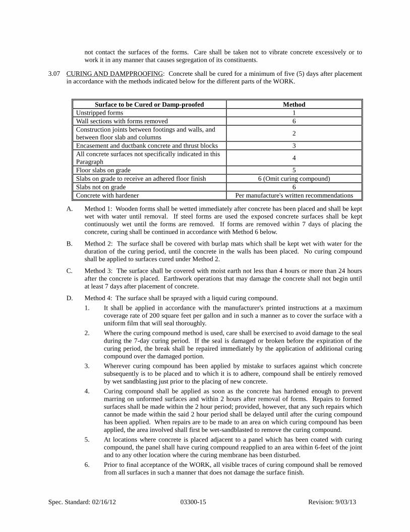
Spec. Standard: 02/16/12 03300-15 Revision: 9/03/13
not contact the surfaces of the forms. Care shall be taken not to vibrate concrete excessively or to work it in any manner that causes segregation of its constituents.
CURING AND DAMPPROOFING: Concrete shall be cured for a minimum of five (5) days after placement 3.07 in accordance with the methods indicated below for the different parts of the WORK.
Surface to be Cured or Damp-proofed Method Unstripped forms 1 Wall sections with forms removed 6 Construction joints between footings and walls, and between floor slab and columns 2
Encasement and ductbank concrete and thrust blocks 3 All concrete surfaces not specifically indicated in this Paragraph 4
Floor slabs on grade 5 Slabs on grade to receive an adhered floor finish 6 (Omit curing compound) Slabs not on grade 6 Concrete with hardener Per manufacture's written recommendations
A. Method 1: Wooden forms shall be wetted immediately after concrete has been placed and shall be kept wet with water until removal. If steel forms are used the exposed concrete surfaces shall be kept continuously wet until the forms are removed. If forms are removed within 7 days of placing the concrete, curing shall be continued in accordance with Method 6 below.
B. Method 2: The surface shall be covered with burlap mats which shall be kept wet with water for the duration of the curing period, until the concrete in the walls has been placed. No curing compound shall be applied to surfaces cured under Method 2.
C. Method 3: The surface shall be covered with moist earth not less than 4 hours or more than 24 hours after the concrete is placed. Earthwork operations that may damage the concrete shall not begin until at least 7 days after placement of concrete.
D. Method 4: The surface shall be sprayed with a liquid curing compound. 1. It shall be applied in accordance with the manufacturer's printed instructions at a maximum
coverage rate of 200 square feet per gallon and in such a manner as to cover the surface with a uniform film that will seal thoroughly.
2. Where the curing compound method is used, care shall be exercised to avoid damage to the seal during the 7-day curing period. If the seal is damaged or broken before the expiration of the curing period, the break shall be repaired immediately by the application of additional curing compound over the damaged portion.
3. Wherever curing compound has been applied by mistake to surfaces against which concrete subsequently is to be placed and to which it is to adhere, compound shall be entirely removed by wet sandblasting just prior to the placing of new concrete.
4. Curing compound shall be applied as soon as the concrete has hardened enough to prevent marring on unformed surfaces and within 2 hours after removal of forms. Repairs to formed surfaces shall be made within the 2 hour period; provided, however, that any such repairs which cannot be made within the said 2 hour period shall be delayed until after the curing compound has been applied. When repairs are to be made to an area on which curing compound has been applied, the area involved shall first be wet-sandblasted to remove the curing compound.
5. At locations where concrete is placed adjacent to a panel which has been coated with curing compound, the panel shall have curing compound reapplied to an area within 6-feet of the joint and to any other location where the curing membrane has been disturbed.
6. Prior to final acceptance of the WORK, all visible traces of curing compound shall be removed from all surfaces in such a manner that does not damage the surface finish.

Spec. Standard: 02/16/12 03300-16 Revision: 9/03/13
E. Method 5: 1. Until the concrete surface is covered with curing compound, the entire surface shall be kept
damp by applying water using nozzles that atomize the flow so that the surface is not marred or washed. The concrete shall be given a coat of curing compound in accordance with Method 4 above. Not less than one hour or more than 4 hours after the curing compound has been applied, the surface shall be wetted with water delivered through a fog nozzle, and concrete-curing blankets shall be placed on the slabs. The curing blankets shall be polyethylene sheet, polyethylene-coated waterproof paper sheeting, or polyethylene-coated burlap. The blankets shall be laid with the edges butted together and with the joints between strips sealed with 2-inch wide strips of sealing tape or with edges lapped not less than 3-inches and fastened together with a waterproof cement to form a continuous watertight joint.
2. The curing blankets shall be left in place during the 7-day curing period and shall not be removed until after concrete for adjacent work has been placed. If the curing blankets become torn or otherwise ineffective, the CONTRACTOR shall replace damaged sections. During the first 3 days of the curing period, no traffic of any nature and no depositing, temporary or otherwise, of any materials shall be permitted on the curing blankets. During the remainder of the curing period, foot traffic and temporary depositing of materials that impose light pressure will be permitted only on top of plywood sheets 5/8-inch minimum thickness, laid over the curing blanket. The CONTRACTOR shall add water under the curing blanket as often as necessary to maintain damp concrete surfaces at all times.
F. Method 6: This method applies to both walls and slabs. 1. The concrete shall be kept continuously wet by the application of water for a minimum period
of at least 7 consecutive days beginning immediately after the concrete has reached final set or forms have been removed.
2. Until the concrete surface is covered with the curing medium, the entire surface shall be kept damp by applying water using nozzles that atomize the flow so that the surface is not marred or washed.
3. Heavy curing mats shall be used as a curing medium to retain the moisture during the curing period. The curing medium shall be weighted or otherwise held substantially in contact with the concrete surface to prevent being dislodged by wind or any other causes. Edges shall be continuously held in place.
4. The curing blankets and concrete shall be kept continuously wet by the use of sprinklers or other means both during and after normal working hours.
5. Immediately after the application of water has terminated at the end of the curing period, the curing medium shall be removed, the entire concrete surface shall be wetted, and curing compound shall be immediately applied to the entire surface in accordance with Method 4 above.
6. The CONTRACTOR shall dispose of excess water from the curing operation to avoid damage to the WORK.
CONCRETE FINISHES: 3.08
A. General: Surfaces shall be free from fins, bulges, ridges, offsets, honeycombing, or roughness of any kind, and shall present a finished, smooth, continuous hard surface. Allowable deviations from plumb or level and from the alignment, profiles, and dimensions indicated are defined as tolerances and are indicated herein. These tolerances are to be distinguished from irregularities in finish as described herein. Aluminum finishing tools shall not be used
B. Formed Surfaces: No treatment is required after form removal except for curing, repair of defective concrete, and treatment of surface defects. Where architectural finish is required, it shall be as indicated.

Spec. Standard: 02/16/12 03300-17 Revision: 9/03/13
C. Unformed Surfaces:
After proper and adequate vibration and tamping, unformed top surfaces of slabs, floors, walls, and curbs shall be brought to a uniform surface with suitable tools. Immediately after the concrete has been screeded, it shall be treated with a liquid evaporation retardant. The retardant shall be used again after each work operation as necessary to prevent drying shrinkage cracks. The classes of finish for unformed concrete surfaces are designated and defined as follows:
Area Finish Grade slabs and foundations to be covered with concrete or fill material U1
Slabs to be covered with topping grout U2 Slabs not water bearing U4 Slabs to be covered with built-up roofing U2 Top surface of walls subject to foot traffic U4 Top surface of walls not subject to foot traffic U3 Floors to receive surface hardener U5
1. Finish U1 - Sufficient leveling and screeding to produce an even, uniform surface with surface
irregularities not to exceed 3/8-inch. No further special finish is required. 2. Finish U2 - (Float Finish)
a. Compact, accurately screed and float to a true uniform surface. b. Surfaces shall be floated with wood or metal floats or a finishing machine using float
blades. Excessive floating of surfaces while the concrete is plastic and dusting of dry cement and sand on the concrete surface to absorb excess moisture will not be permitted.
c. Floating shall be the minimum necessary to produce a surface that is free from screed marks and is uniform in texture. Test surface with straightedge and eliminate high and low spots of more than 1/8 inch in 10 feet. Surface irregularities shall not exceed 1/4-inch.
d. Joints and edges shall be tooled where indicated or as determined by the DISTRICT. 3. Finish U3 - (Hand-Troweled Finish)
a. Finish surface as in Finish U2 - Float Finish and after the surface has hardened sufficiently to prevent excess of fine material from being drawn to the surface, trowel with steel trowel to obtain a smooth dense finish after concrete has hardened to ring under the trowel.
b. The finish shall produce a smooth dense uniform surface free of all irregularities, blemishes, ripples, and trowel marks.
4. Finish U4 - (Nonskid Finish) a. Trowel the Finish U3 - Hand-trowel Finish surface to remove local depressions or high
points. In addition, the surface shall be given a light broom finish with brooming perpendicular to drainage unless otherwise indicated.
b. The resulting surface shall be rough enough to provide a nonskid finish. 5. Finish U5 - (Surface hardener)
a. Immediately after screeding, shake-on hardener shall be applied per the manufacturer's written recommendations.
b. Surface shall receive a minimum of two coats of a liquid hardener per the manufacturer's written recommendations.
c. CONTRACTOR shall notify hardener manufacturer three (3) working days prior to hardened concrete floor being placed.

Spec. Standard: 02/16/12 03300-18 Revision: 9/03/13
d. Hardener manufacturer shall provide continuous supervision of concrete and hardener placements, supplying DISTRICT with a report of each day's placement. Cost of supervision is to be borne by CONTRACTOR.
ARCHITECTURAL FINISH: 3.09
A. General: Architectural finishes shall be provided only where specifically indicated below. In all other locations, the paragraph entitled Concrete Finishes shall apply.
Location Finish Generator Building – Concrete Tie Beams and Columns
Burlap Finish
B. Immediately after the forms have been stripped, the concrete surface shall be inspected and any poor joints, voids, rock pockets, or other defective areas shall be repaired and form-tie holes filled as indicated herein.
C. Architectural finishes shall not be applied until the concrete surface has been repaired as required and the concrete has cured at least 14 days.
D. Architecturally treated concrete surfaces shall conform to the accepted sample in texture, color, and quality. It shall be the CONTRACTOR'S responsibility to maintain and protect the concrete finish.
E. Burlap Finish: 1. Wet and fill all voids using mortar with the same sand-cement ratio as original concrete. Use
approximately 20 percent white cement to match concrete color. 2. The freshly applied grout shall be vigorously rubbed into the concrete surface with a wood float
filling all small air holes. After all the surface grout has been removed with a steel trowel, the surface shall be allowed to dry.
3. Once dry, strike off all excess mortar flush with the surface using a burlap or canvas cloth with a circular motion.
4. Remove all rough spots and rub with cloth to leave a surface of uniform texture and appearance without any appearance of a paint or grout film.
5. Finish shall result in a coating of mortar that will fill all small voids and air holes, leaving a smooth surface.
6. Cure as specified under "Curing Concrete". 7. The entire cleaning operation for any area shall be completed the day it is started, and no grout
shall be left on the surface overnight. 8. Cleaning operations for any given day shall be terminated at panel joints. It is required that the
various operations be carefully timed to secure the desired effect. 9. Before beginning any of the final treatment on exposed surfaces, the CONTRACTOR shall
treat in a satisfactory manner a trial area of at least 200 square feet in some inconspicuous place selected by the DISTRICT and shall preserve said trial area undisturbed until the completion of the job.
PROTECTION: 3.10
A. The CONTRACTOR shall protect concrete against injury until final acceptance.
B. Fresh concrete shall be protected from damage due to rain, hail, sleet, or snow. The CONTRACTOR shall provide such protection while the concrete is still plastic and whenever precipitation is imminent or occurring.
DEFECTIVE SURFACE TREATMENTS: 3.11
A. Patching Concrete: 1. Patch all tie holes, honeycombs or other defects with a Portland cement and sand grout.
Spec. Standard: 02/16/12 03300-19 Revision: 9/03/13
2. Defective surfaces to be repaired shall be cut back from trueline a minimum depth of 1/2-inch over the entire area. Feathered edges will not be permitted. Where chipping or cutting tools are not required in order to deepen the area properly, the surface shall be prepared for bonding by the removal of all laitance or soft material, plus not less than 1/32-inch depth of the surface film from all hard portions by means of an efficient sandblast.
3. After cutting and sandblasting, the surface shall be wetted sufficiently in advance of shooting with shotcrete or with cement mortar so that while the repair material is being applied, the surfaces underneath will remain moist but not so wet as to overcome the suction upon which a good bond depends.
4. Holes left by tie-rod cones shall be reamed with suitable toothed reamers so as to leave the surfaces of the holes clean and rough. Holes then shall be repaired in an approved manner with dry-packed cement grout. Holes left by form-tying devices having a rectangular cross-section and other imperfections having a depth greater than their least surface dimension shall not be reamed but shall be repaired in an approved manner with dry-packed cement grout.
5. The grout shall not be richer than one (1) part cement and three (3) parts sand with the amount of mixing water enough to produce a workable mix. For exposed walls, the cement shall contain such a proportion of white Portland cement as is required to make the color of the patch match the color of the surrounding concrete. The patch shall be finished in such a manner as to match the adjoining surfaces.
6. Surfaces of repairs shall receive the same kind and amount of curing treatment as required for the concrete in the repaired section.
B. Defective Concrete: 1. Any concrete which is not formed as shown on the Drawings or does not conform to the
Contract tolerances or shows defects which reduce its structural adequacy, shall be removed from the job by the CONTRACTOR at his expense unless the DISTRICT grants permission to patch the defective area.
C. Exposed Concrete Surfaces: 1. As soon as forms are removed, exposed surfaces shall be carefully examined and all ridges, ribs
and other imperfections shall be rubbed with an abrasive stone or ground in a satisfactory manner in order to secure a smooth, uniform and continuous surface. Plastering or coating of surfaces to be smoothed will not be permitted
2. No repairs shall be made until after inspection by the DISTRICT. 3. In no case will extensive patching of honeycombed concrete be permitted 4. Concrete containing minor voids, pinholes, honeycombing, or similar depression defects shall
be repaired as indicated above. 5. Concrete containing extensive voids, holes, honeycombing, or similar depression defects shall
be completely removed and replaced. Repairs and replacements shall be performed promptly.
REINFORCEMENT: Reinforcement shall be in accordance with SECTION 03200 Concrete Reinforcement, 3.12 of these Specifications. Concrete protection for the reinforcement shall conform to the requirements ACI 318, paragraph 7.7.1, unless otherwise specified on the Contract Documents.
CONSTRUCTION TOLERANCES: 3.13
A. The CONTRACTOR shall set and maintain concrete forms and perform finishing operations to ensure that the completed WORK is within tolerances. Surface defects and irregularities are defined as finishes and are to be distinguished from tolerances. Tolerance is the permissible variation from lines, grades, or dimensions indicated on the Drawings. Where tolerances are not stated in the specifications, permissible deviations will be in accordance with ACI 117.
B. The following non-cumulative construction tolerances apply to finished walls and slab unless otherwise indicated:

Spec. Standard: 02/16/12 03300-20 Revision: 9/03/13
Item Tolerance Variation of the constructed linear outline from the established position in plan.
In 10-feet: 1/4-inch; In 20-feet or more: 1/2-inch
Variation from the level or from the grades indicated. In 10-feet: 1/4-inch; In 20-feet or more: 1/2-inch
Variation from plumb In 10-feet: 1/4-inch; In 20-feet or more: 1/2-inch
Variation in the thickness of slabs and walls. Minus 1/4-inch; Plus 1/2-inch
Variation in the locations and sizes of slabs and wall openings
Plus or minus 1/4-inch
CARE AND REPAIR OF CONCRETE: The CONTRACTOR shall protect concrete against injury or damage 3.14 from excessive heat, lack of moisture, overstress, or any other cause until final acceptance. Particular care shall be taken to prevent the drying of concrete and to avoid roughening or otherwise damaging the surface. Any concrete found to be damaged, or which may have been originally defective, or which becomes defective at any time prior to the final acceptance of the completed WORK, or which departs from the established line or grade, or which, for any other reason, does not conform to the requirements of the Contract Documents, shall be satisfactorily repaired or removed and replaced with acceptable concrete.
END OF SECTION

Spec. Standard: 02/16/12 03312-1 Revision: 10/2/13
SECTION 03312 SELF-CONSOLIDATING CONCRETE (SCC)
GENERAL PART 1 -
SCOPE: 1.01
A. The work of this Section specifies materials and procedures for producing Self-Consolidating Concrete (SCC) required by the Contract Documents. 1. SECTION 03050 Concrete Admixture Waterproofing 2. SECTION 03100 Concrete Formwork and Accessories 3. SECTION 03200 Concrete Reinforcement 4. SECTION 03300 Cast-In-Place Concrete 5. SECTION 03600 Grout
APPLICABLE PUBLICATIONS: The following standard specifications shall apply to the Work of this 1.02 Section:
A. American Concrete Institute (ACI) 1. ACI 117 – Specification for Standard Tolerance for Concrete Construction and Materials 2. ACI 237R-07 - Self-Consolidating Concrete 3. ACI 301 – Specifications for Structural Concrete 4. ACI 304.2R - Recommended Practice for Measuring, Mixing, Transporting, and Placing
Concrete 5. ACI 305 - Committee Report on Hot-Weather Concreting 6. ACI 306 - Committee Report on Cold-Weather Concreting 7. ACI 308 - Standard Specification for Curing Concrete 8. ACI 309 - Consolidation of Concrete 9. ACI 318 - Building Code Requirements for Reinforced Concrete 10. ACI 350 – Code Requirements for Environmental Engineering Concrete Structures
B. American Society for Testing and Materials (ASTM): 1. C31 - Making and Curing Concrete compression and Flexure Test Specimens in the Field 2. C33 - Concrete Aggregates 3. C39 - Compressive Strength of Cylindrical Concrete Specimens 4. C 70 - Standard Test Method for Surface Moisture in Fine Aggregate 5. C94 - Ready-Mixed Concrete 6. C127 - Test Method for Specific Gravity and Absorption of Coarse Aggregate 7. C128 - Test Method for Specific Gravity and Absorption of Fine Aggregate 8. C136 - Method for Sieve Analysis of Fine and Coarse Aggregates 9. C 138 - Standard Test Method for Density (Unit Weight), Yield, and Air Content (Gravimetric)
of Concrete 10. C143 - Test Method for Slump of Hydraulic Cement Concrete 11. C150 - Standard Specification for Portland Cement 12. C156 - Test Method for Water Retention by Concrete Curing Materials 13. C157 - Test Method for Length Change of Hardened Hydraulic Cement Mortar and Concrete 14. C172 - Standard Practice for Sampling Freshly Mixed Concrete 15. C173 - Standard Test Method for Air Content of Freshly Mixed Concrete by the Volumetric
Method

Spec. Standard: 02/16/12 03312-2 Revision: 10/2/13
16. C231 - Standard Test Method for Air Content of Freshly Mixed Concrete by the Pressure Method
17. C260 - Specification for Air Entraining Admixtures for Concrete 18. C309 - Liquid Membrane-Forming Compounds for Curing Concrete 19. C494 - Chemical Admixtures for Concrete 20. C566 - Test Method for Total Moisture Content of Aggregate by Drying 21. C618 - Standard Specification for Coal Fly Ash and Raw or Calcined Natural Pozzolan for Use
as a Mineral Admixture in Concrete 22. A820 - Standard Specification for Steel Fibers for Fiber-Reinforced Concrete 23. C881 - Standard Specification for Epoxy-Resin-Base Bonding Systems for Concrete 24. C 989 - Standard Specification for Slag Cement for Use in Concrete and Mortars 25. C1017 - Standard Specification for Chemical Admixtures for Use in Producing Flowing
Concrete 26. C1064 - Standard Test Method for Temperature of Freshly Mixed 27. C1077 - Practice for Laboratories Testing Concrete and Concrete Aggregates for use in
Construction and Criteria for Laboratory Evaluation 28. C1116 - Standard Specification for Fiber-Reinforced Concrete 29. C1157 – Performance Specification for Hydraulic Cements 30. C1240 - Standard Specification for Silica Fume for Use as a Mineral Admixture in Hydraulic-
Cement Concrete, Mortar, and Grout 31. C1550 - Standard Test Method for Flexural Toughness of Fiber Reinforced Concrete (Using
Centrally Loaded Round Panel) 32. C1579 - Standard Test Method for Evaluating Plastic Shrinkage Cracking of Restrained Fiber
Reinforced Concrete (Using a Steel Form Insert) 33. C1582 - Standard Specification for Admixtures to Inhibit Chloride Induced Corrosion of
Reinforcing Steel in Concrete 34. C1585 - Standard Test Method for Measurement of Rate of Absorption of Water by Hydraulic-
Cement Concretes 35. C1602 - Standard Specification for Mixing Water Used in the Production of Hydraulic Cement
Concrete 36. C1609 - Standard Test Method for Flexural Performance of Fiber- Reinforced Concrete (Using
Beam With Third-Point Loading) 37. C1610 - Standard Test Method for Static Segregation of Self- Consolidating Concrete Using
Column Technique 38. C1611 - Standard Test Method for Slump Flow of Self-Consolidating Concrete 39. C1621 - Standard Test Method for Passing Ability of Self- Consolidating Concrete by J-Ring 40. D1751 - Standard Specification for Preformed Expansion Joint Filler for Concrete Paving and
Structural Construction (Nonextruding and Resilient Bituminous Types) 41. D2419 - Test Methods for Sand Equivalent Value of Soils and Fine Aggregate 42. E96 - Water Vapor Transmission of Materials 43. E329 - Standard Specification for Agencies Engaged in Construction Inspection and/or Testing 44. E1643 - Standard Practice for Installation of Water Vapor Retarders Used in Contact with Earth
or Granular Fill Under Concrete Slabs 45. F 1869 - Standard Test Method for Measuring Moisture Vapor Emission Rate of Concrete
Subfloor Using Anhydrous Calcium Chloride
C. Federal Specifications 1. UU-B-790A - Building Paper, Vegetable Fiber (Kraft, Waterproofed, Water Repellant and Fire
Resistant)
Spec. Standard: 02/16/12 03312-3 Revision: 10/2/13
D. National Sanitation Foundation International/American National Standards Institute (NSF/ANSI) 1. NSF/ANSI 61 Drinking Water System Components - Health Effects
E. DIN (Deutsches Institut Fur Normung, Germany) 1. DIN 1048 Part 5 "Testing Concrete - Testing of hardened concrete (specimens prepared in
mould)”
F. Florida Department of Transportation Standard Specifications for Road and Bridge Construction, Latest Edition
G. 2010 Florida Building Code, Building and Local Building Codes as appropriate
DEFINITIONS: 1.03
A. Structural Concrete: Concrete to be used in all cases except where indicated otherwise in the Contract Documents.
B. Structural Silica Fume Concrete: Silica Fume Concrete shall contain a Silica Fume Admixture per the manufacturer's recommendations.
C. Structural Chloride Resistant Concrete: Chloride Resistant Concrete shall contain a Corrosion Inhibitor per the manufacturer's recommendations.
D. Hydraulic Structure: An environmental engineering concrete structure for the containment, treatment, or transmission of water, wastewater, other fluids, or gases
E. Self-Consolidating Concrete (SCC): A highly flowable, non-segregating concrete that can spread into place, fill the formwork, and encapsulate the reinforcement without any mechanical consolidation.
F. Passing Ability: The ability of self-consolidating concrete to flow under its own weight (without vibration) and fill completely all spaces within intricate formwork, containing obstacles, such as reinforcement.
G. J-Ring Test: Test used to determine the passing ability of self-consolidating concrete, or the degree to which the passage of concrete through the bars of the J-Ring apparatus is restricted.
H. J-Ring Flow: The distance of lateral flow of concrete using the J-Ring in combination with a slump cone.
I. Slump Flow: Test method used to measure the unconfined flow and stability of self-consolidating concrete using a slump cone (upright or inverted).
J. Slump Flow Spread: The numerical value in inches of flow determined as the average diameter of the circular deposit of self-consolidating concrete at the conclusion of the slump flow test.
K. T50 Value: Time (in seconds) the edge of the concrete mass takes to reach 20-inch diameter from the time the mold is first raised in the slump flow test.
L. Stability: The ability of a concrete mixture to resist segregation of the paste from the aggregates.
M. Static Segregation (Segregation Factor): Segregation of the mortar from the coarse aggregate that occurs after placement while the concrete is still in a plastic state.
N. Visual Stability Index (VSI) Rating: An assessment of the homogeneity of concrete based on the visual inspection of the concrete sample at the end of the slump flow test.
SUBMITTALS: 1.04
A. The CONCTRACTOR shall submit signed and sealed design shop drawings and calculations for the formwork and shoring required for pumping self-consolidating concrete. The submittal shall be signed and sealed by a Florida registered professional engineer.
B. The CONTRACTOR shall submit the Producer’s Quality Control Plan and the Contractor’s Quality Control Plan.
Spec. Standard: 02/16/12 03312-4 Revision: 10/2/13
C. Mix Designs: 1. Prior to beginning the WORK and within 14 days of the Notice to Proceed, the
CONTRACTOR shall submit preliminary concrete mix designs which shall show the proportions and gradations of all materials proposed for each class and type of concrete. Mix designs shall be checked by an independent testing laboratory conforming to the requirements of ASTM E 329 and acceptable to the DISTRICT. All costs related to such checking shall be CONTRACTOR’S responsibility.
2. Perform trial batch in accordance with the proposed batching sequence and mixing time that are included in the Producer’s Quality Control Plan. a. Description of the mix design qualification process if the anticipated placing temperature
will be below or above 85 degrees Fahrenheit. b. Concrete batching sequence, mixing methods and duration, and delivery. c. The proposed sources of concrete materials ingredients. d. The proposed inspection and test methods for the laboratory trial batches. e. The frequency and test methods of the aggregate moisture content tests. f. The qualifications and experience of the personnel performing the required mixing,
delivery, and testing of the self-consolidating concrete. The CONTRACTOR shall notify the DISTRICT three working days prior to performing the trial batch.
3. Test data from trial batch relating to the cement, aggregate, and admixtures shall be furnished in accordance with ACI 301 for the following: a. Mixture proportions b. Mill tests for cement c. Admixture certification. Chloride ion content shall be included. d. Aggregate gradation test results and certification e. Certification: Manufacturer’s certification stating that the products delivered meet or
exceed Project Specifications. f. Product data
D. Delivery Tickets 1. Where ready-mix concrete is used, the CONTRACTOR shall furnish delivery tickets at the time
of delivery of each load of concrete. Ready-mixed concrete truck driver shall provide batch ticket to the DISTRICT at the time of concrete delivery. Contents of the batch ticket shall be as specified in ASTM C94. Each ticket shall show the state certified equipment used for measuring and the total quantities, by weight, of cement, sand, each class of aggregate, admixtures, and the amounts of water in the aggregate added at the batching plant. Water shall not be added to re-temper the concrete. In addition, each ticket shall state the mix number, total yield in cubic yards, and the time of day, to the nearest minute, corresponding to the times when the batch was dispatched, when it left the plant, when it arrived at the Site, when unloading began, and when unloading was finished..
E. Other 1. The CONTRACTOR shall submit materials and methods for curing. 2. The CONTRACTOR shall submit product specifications, data, and installation instructions for
all miscellaneous products called for in this specification.
QUALIFICATIONS: 1.05
A. Truck mixers shall be equipped with electrically actuated counters by which the number of revolutions of the drum or blades may be readily verified. The counter shall be of the resettable, recording type, and shall be mounted in the driver's cab. The counters shall be actuated at the time of starting mixers at mixing speeds.

Spec. Standard: 02/16/12 03312-5 Revision: 10/2/13
B. The CONTRACTOR shall have a minimum of five (5) years experience in placing self-consolidating concrete for repair and construction of vertical walls, columns and horizontal beams.
CERTIFICATIONS AND TESTING: 1.06
A. General 1. Concrete and other materials for testing shall be furnished by the CONTRACTOR, and the
CONTRACTOR shall assist the DISTRICT in obtaining samples, and disposal and cleanup of excess material.
2. The testing laboratory will meet or exceed the requirements of ASTM C1077. 3. The cost of trial batch, laboratory, and shrinkage tests on cement, aggregates, and concrete, will
be the CONTRACTOR'S responsibility.
B. Trial Batch and Laboratory Tests 1. Tests for determining slump flow shall be in accordance with the requirements of ASTM
C1611. 2. Testing for aggregate shall include sand equivalence, reactivity, organic impurities, abrasion
resistance, and soundness, according to ASTM C33. 3. A testing laboratory approved by the DISTRICT shall prepare a trial batch of each class of
concrete, based on the preliminary concrete mixes submitted by the CONTRACTOR. During the trial batch the aggregate proportions may be adjusted by the testing laboratory to obtain the required properties. Such adjustments will be considered refinements to the mix design and will not be the basis for extra compensation to the CONTRACTOR. Concrete shall conform to the requirements of this Section, whether the aggregate proportions are from the CONTRACTOR'S preliminary mix design, or whether the proportions have been adjusted during the trial batch process. The trial batch shall be prepared using the aggregates, cement, and admixture proposed for the project. The trial batch materials shall be of a quantity such that the testing laboratory can obtain 3 drying shrinkage, and 6 compression test specimens from each batch.
4. The determination of compressive strength shall be made in accordance with ACI 318, Section 5.3.
5. A sieve analysis of the combined aggregate for each trial batch shall be performed according to the requirements of ASTM C136. Values shall be given for percent passing each sieve.
C. Field Tests 1. The responsibility to retain the services of an independent testing laboratory shall be as defined
in SECTION 01410. 2. The CONTRACTOR shall pay the cost of any additional tests and investigation on WORK that
does not meet the specifications. 3. Tests on pumped concrete shall be taken at the point of final placement. 4. Compressive Test:
a. Compressive test specimens shall be taken during construction from the first placement of each class of concrete placed each day and for each 150 cubic yards or fraction thereof each day.
b. Each set of test specimens shall consist of 5 cylinders. Specimens shall be made in accordance with ASTM C31. Specimens shall be 6-inch diameter by 12-inch high cylinders.
c. Compression tests shall be performed in accordance with ASTM C39. Two (2) cylinders shall be broken at 7 days and two (2) at 28 days, and the remaining cylinder shall be held to verify test results, if needed.
d. The acceptance of the test results shall be the average of the strengths of the two specimens tested at 28 days as per ACI 318. Evaluation and acceptance of the concrete shall be per ACI 318, Chapter 5.

Spec. Standard: 02/16/12 03312-6 Revision: 10/2/13
5. Slump Flow Tests: One (1) slump test shall be taken per truckload in accordance with ASTM C1611.
6. Air Content: Air content shall be determined for each compressive test taken in accordance with ASTM C231 or by ASTM C173.
7. Aggregate testing shall be made every 12 months during construction to insure continued compliance with these Specifications.
8. Concrete that fails to meet the ACI requirements and these Specifications is subject to removal and replacement.
9. Temperature: Concrete temperature shall be recorded in accordance with ASTM C1064. 10. J-Ring Test and J-Ring Flow: Testing shall be in accordance with ASTM C-1621.
SELF-CONSOLIDATING CONCRETE CONFERENCE: 1.07
A. A meeting to review the detailed requirements of the CONTRACTOR'S proposed self-consolidating concrete design mixes and to determine the procedures for producing proper concrete construction shall be held no later than 14 days after the Notice to Proceed.
B. All parties involved in the concrete work shall attend the conference, including the following at a minimum: 1. CONTRACTOR'S representative 2. Testing laboratory representative 3. Concrete subcontractor 4. Reinforcing steel subcontractor and detailer 5. Concrete supplier 6. Admixture manufacturer's representative
C. The conference shall be held at a mutually agreed upon time and place. The DISTRICT shall be notified no less than 5 days prior to the date of the conference.
WARRANTY: 1.08
A. The CONTRACTOR shall warrant the WORK against defects for one year from the date of Substantial Completion and as described in Article 13 of Section 00700 - General Terms and Conditions.
MATERIALS PART 2 -
GENERAL: 2.01
A. All materials shall be classified as acceptable for potable water use according to NSF Standard 61.
B. Cement for concrete that will contact potable water shall not be obtained from kilns that burn metal rich hazardous waste fuel.
C. Materials shall be delivered, stored, and handled so as to prevent damage by water or breakage. Cement reclaimed from cleaning bags or leaking containers shall not be used. Cement shall be used in the sequence of receipt of shipments.
D. Materials shall comply with the requirements of ACI 301, as applicable.
E. Storage of materials shall conform to the requirements of Section 205 of ACI 301.
CEMENT: 2.02
A. Cement shall be standard Portland Cement Type II conforming to ASTM C150 and C1157. A minimum of 85 percent of cement by weight shall pass a 325 screen. Silica fume and flyash shall each be a minimum of 10% by mass of cement content.
B. A single brand of cement shall be used throughout the WORK, and prior to its use, the brand shall be accepted by the DISTRICT.

Spec. Standard: 02/16/12 03312-7 Revision: 10/2/13
C. Sacked cement shall be stored in such a manner so as to permit access for inspection and sampling. Certified mill test reports, including fineness, for each shipment of cement to be used shall be submitted to the DISTRICT, if requested, regarding compliance with these Specifications.
AGGREGATES: 2.03
A. Aggregates shall be obtained from pits acceptable to the DISTRICT, shall be non-reactive, and shall conform to the requirements of ASTM C33.
B. When tested in accordance with ASTM C33, the loss resulting after 5 cycles of the soundness test, shall not exceed 10 percent for fine aggregate and 12 percent for coarse aggregate, when using sodium sulfate.
C. When tested in accordance with ASTM C33, the ratio of silica released to reduction in alkalinity shall not exceed 1.0.
D. Coarse Aggregates: 1. Coarse aggregates shall be crushed stone, gravel or other approved inert material having clean,
hard, durable, uncoated particles conforming to ASTM C33. 2. The coarse aggregates shall be prepared and handled in 2 or more size groups for combined
aggregates with a maximum size greater than 3/4-inch. When the aggregates are proportioned for each batch of concrete, the 2 size groups shall be combined.
3. When tested in accordance with ASTM C33, the coarse aggregate shall show a loss not exceeding 42 percent after 500 revolutions, or 10.5 percent after 100 revolutions.
E. Fine Aggregates: 1. Fine aggregates shall be clean sand conforming to ASTM C33. 2. When tested in accordance with ASTM D2419, the sand equivalency shall not be less than 75
percent for an average of 3 samples, nor less than 70 percent for an individual test. Gradation of fine aggregate shall conform to ASTM C33 when tested in accordance with ASTM C136 for the fineness modulus of the sand used, including the optional grading in Section 6.2. The fineness modulus of sand used shall not be over 3.1.
3. When tested in accordance with ASTM C33, the fine aggregate shall produce a color in the supernatant liquid no darker than the reference standard color solution.
WATER: 2.04
A. The water used in the concrete mix and for curing shall be clean, potable, and in accordance with ASTM C1602 and ACI 301 and ACI 318. Water shall be free from objectionable quantities of silty organic matter, alkali, salts, and other impurities.
B. The water shall be considered potable, for the purposes of this SECTION only, if it meets the requirements of the local governmental agencies. Agricultural water with high total dissolved solids (over 1000 mg/l TDS) shall not be used.
ADMIXTURES: 2.05
A. General: All admixtures shall be compatible and be furnished by a single MANUFACTURER capable of providing qualified field service representation. Admixtures shall be used in accordance with MANUFACTURER's recommendations. If the use of an admixture is producing an inferior end result, the CONTRACTOR shall discontinue use of the admixture. Admixtures shall not contain thiocyanates or more than 0.05 percent chloride ion, and shall be non-toxic after 30 days.
B. Air Entraining Admixtures: 1. Air entraining admixture shall conform to ASTM C260. Air content shall be tested at the point
of placement. 2. The air-entraining agent shall be added to the batch in a portion of the mixing water. The
solution shall be batched by means of a mechanical batcher capable of accurate measurement.

Spec. Standard: 02/16/12 03312-8 Revision: 10/2/13
3. Sufficient air-entraining agent shall be used to provide a total air content of 3 percent.
C. Set Controlling and Water Reducing Admixtures: 1. Admixtures may be added at the CONTRACTOR'S option, subject to the DISTRICT'S
approval, to control the set, effect water reduction, and increase workability. The cost of adding an admixture shall be the CONTRACTOR'S responsibility. Concrete containing an admixture shall be first placed at a location determined by the DISTRICT. Admixtures shall conform to the requirements of ASTM C494. The required quantity of cement shall be used in the mix regardless of whether or not an admixture is used.
2. Concrete shall not contain more than one water-reducing admixture. 3. Set retarding admixture may be either with or without water-reducing properties. Where the air
temperature at the time of placement is expected to be consistently greater than 80 degrees F, a set retarding admixture shall be used. Set retarding admixture shall conform to ASTM C494 Type B or D.
4. Set accelerating admixture may be either with or without water-reducing properties. Where the air temperature at the time of placement is expected to be consistently less than 40 degrees F, a non-corrosive set accelerating admixture shall be used. Set accelerating admixture shall conform to ASTM C494 Type C or E.
5. Normal range water reducer shall conform to ASTM C494, Type A. The quantity of admixture used and the method of mixing shall be in accordance with the manufacturer's instructions and recommendations.
6. High range water reducer shall conform to ASTM C494, Type F. High range water reducer shall be added to the concrete after all other ingredients have been mixed and initial slump has been verified. No more than 14 ounces of water reducer per sack of cement shall be used. Water reducer shall be considered as part of the mixing water when calculating the water/cement ratio. a. If the high range water reducer is added to the concrete at the Site, it may be used in
conjunction with the same water reducer added at the batch plant. The high range water reducing admixture shall be accurately measured and pressure injected into the mixer as a single dose by an experienced technician. A standby system shall be provided and tested prior to each day's operation of the primary system.
b. Concrete shall be mixed at mixing speed for a minimum of 70 mixer revolutions or 5 minutes after the addition of the high range water reducer, unless recommended otherwise by the manufacturer.
D. Accelerating Admixture: Accelerating admixture shall conform to ASTM C494 Type C or E
E. Hydration Control Admixture: Hydration control admixture shall conform to ASTM C494 Type B or D
F. Workability-Retaining Admixture: Workability-retaining admixture shall retain concrete workability without affecting time of setting or early-age strength development and shall conform to ASTM C494 Type S.
G. Permeability-Reducing Admixture: Permeability-reducing admixture shall be an integral crystalline capillary waterproofing admixture for concrete as specified in Section 03050. It shall satisfy the following requirements, when used at the Manufacturer's recommended dosage: 1. Reduction in capillary absorption: Not less than 40 percent relative to a companion untreated
concrete mixture, when tested in accordance with ASTM C 1585 2. Reduction in water penetration: Not less than 40 percent relative to a companion untreated
concrete mixture, when tested in accordance with DIN 1048. 3. The admixture shall not affect the setting time, strength or durability properties of concrete.
H. Viscosity-Modifying Admixture: Viscosity-modifying admixture shall conform to ASTM C494 Type S.
I. Corrosion-Inhibiting Admixture: Corrosion-inhibiting shall be a nominal 30 percent solution of calcium nitrite or an amine/ester-based organic corrosion-inhibiting admixture and shall chemically

Spec. Standard: 02/16/12 03312-9 Revision: 10/2/13
inhibit corrosive action of chlorides on steel. Admixture shall not affect set times of concrete. Mixing water shall be adjusted for the admixture in accordance with the manufacturer’s recommendations.
J. Shrinkage-Reducing Admixture: Shrinkage-reducing admixture shall conform to ASTM C494 Type S.
K. Alkali-Silica Reaction Inhibiting Admixture: Alkali-silica reaction inhibiting admixture shall contain a nominal lithium nitrate content of 30 percent, and shall conform to ASTM C494 Type S.
L. Supplementary Cementitious Materials (SCM): The substitution of supplementary cementitious materials for cement shall be made on the basis of mass. 1. Fly Ash shall conform to ASTM C618 2. Slag Cement shall conform to ASTM C989. 3. Silica Fume Admixture shall conform to ASTM C1240. Blended cements with interground
silica fume will not be allowed. Silica fume admixture shall not affect the setting times of the concrete. a. Water content of liquid slurry silica fume admixtures shall be considered as part of the
mixing water when calculating the water/cement ratio. b. Silica fume shall be added at the batch plant as recommended by the manufacturer. For
all types of mixing equipment, mix times shall be increased by 40 percent over the minimum mix time required to achieve mix uniformity as defined by ASTM C94. For truck-mixed and central mixed concrete, maximum allowable batch size shall be 80 percent of the maximum as called out by ASTM C94
M. Microsynthetic fibers: Microsynthetic fibers shall conform to ASTM C1116, and shall provide a minimum crack reduction ratio (CRR) of 40 percent when tested in accordance with ASTM C 1579.
N. Type S admixture: Specific performance admixtures shall meet the requirements of ASTM C494 Type S. The Type S admixtures, shall be compatible with other admixtures used in the self-consolidating concrete mixture proportions and shall not contain calcium chloride based ingredients.
CURING MATERIALS: 2.06
A. Polyethylene sheet for use as concrete curing blanket shall be white and shall have a nominal thickness of 6 mils. The loss of moisture when determined in accordance with the requirements of ASTM C156 shall not exceed 0.055 grams per square centimeter of surface.
B. Polyethylene-coated waterproof paper sheeting for use as concrete curing blanket shall consist of white polyethylene sheeting free of visible defects, uniform in appearance, have a minimum thickness of 2 mils, and be permanently bonded to waterproof paper conforming to the requirements of Federal Specification UU-B-790A. The loss of moisture, when determined in accordance with the requirements of ASTM C156, shall not exceed 0.055 gram per square centimeter of surface.
C. Polyethylene-coated burlap for use as concrete curing blanket shall be minimum 4-mil thick, white opaque polyethylene film impregnated or extruded into one side of the burlap. Burlap shall weigh not less than 9 ounces per square yard. The loss of moisture, when determined in accordance with the requirements of ASTM C156, shall not exceed 0.055 grams per square centimeter of surface.
D. Curing mats for use in Curing Method 6 shall be heavy shag rugs or carpets or cotton mats quilted at 4-inches on center. Curing mats shall weigh a minimum of 12 ounces per square yard when dry.
MISCELLANEOUS MATERIALS: 2.07
A. Damp proofing agent shall be an asphalt emulsion conforming to ASTM D1227, Type III, Class 1.
B. Evaporation retardant shall create a monomolecular film on the concrete. The retardant shall have no effect on cement hydration and shall meet local VOC requirements. Evaporation retardant shall not affect adhesion of curing compounds or other treatments and shall not affect the color of the concrete.
C. Reinforcement shall be per SECTION 03200 Concrete Reinforcement.
D. Water Stops shall be per SECTION 03100 Concrete Formwork.

Spec. Standard: 02/16/12 03312-10 Revision: 10/2/13
E. Damp proofing agent shall be a waterborne emulsified-asphalt. Damp proofing shall be suitable for "green" or slightly damp surfaces and shall withstand normal expansion and contraction of the concrete. Damp proofing agent shall breathe to allow vapors to escape. Damp proofing agent shall meet local VOC requirements.
F. Vapor Barrier: 1. Vapor Barrier shall consist of a composite of heavy kraft paper, asphalt, fiberglass
reinforcement, and polyethylene film. The composite shall be laminated under heat and pressure.
2. Vapor Barrier shall comply with federal specification UU-B-790A, Type I, Grade A, Style 4. Vapor Barrier shall have a water vapor permeance of less than 0.30 perms when tested per ASTM E96.
3. Vapor Barrier shall be installed under concrete slabs of all habitable spaces. Barrier shall be installed per the manufacturer recommendations and per ASTM E1643.
G. Non-Waterstop Joint Material: 1. Preformed Joint Material: Preformed asphalt-impregnated fiber conforming to ASTM D1751. 2. Bond Breaker: All bond breakers shall be roofing felt or 15 mils minimum dry film thickness
of bituminous paint as indicated.
SELF-CONSOLIDATING CONCRETE DESIGN REQUIREMENTS: 2.08
A. General: The self-consolidating concrete shall be composed of cement, admixtures, aggregates, and water of the qualities indicated. The exact proportions in which these materials are to be used for different parts of the WORK will be determined during the trial batch process. In general, the mix shall be designed to produce a concrete capable of being deposited so as to obtain maximum density and minimum shrinkage, and, where deposited in forms, to have good consolidation properties and maximum smoothness of surface. The aggregate gradations shall be formulated to provide fresh concrete that will not promote rock pockets around reinforcing steel or embedded items. The proportions shall be changed whenever necessary or desirable to meet the required results. All changes shall be subject to review by the DISTRICT
B. Supplementary Cementitious Materials: The weight of SCM shall not exceed the percentages listed in the following table.
Material Maximum Percent of SCM by mass of total cementitious materials
Fly ash of other pozzolans 25 Slag cement 50 Silica Fume 10 Total of Fly ash or other pozzolans, slag cement and silica fume 50*
Total of fly ash or other pozzolans and silica fume 35*
*Fly ash or other pozzolans and silica fume shall not constitute more than 25 and 10 percent, respectively, of the total mass of cementitious material.
C. Fine Aggregate Composition: 1. In mix designs for self-consolidating concrete, the aggregate-volume ratios of fine aggregate-to-
total aggregates, by weight, shall be greater than or equal to 45 percent unless approved by the DISTRICT. The volume ratios of fine-to-total aggregates in a mix design shall not exceed 50 percent.
D. Structural chloride resistant concrete shall contain 4-gallons per cubic yard corrosion inhibiting admixture and a high range water reducer. Workability or strength demands shall be met by additional admixtures, if necessary.

Spec. Standard: 02/16/12 03312-11 Revision: 10/2/13
E. Water/Cement Ratio and Compressive Strength: 1. Water/cement ratio is given for aggregates in saturated-surface dry condition, and total moisture
of all aggregates, calculated by ASTM C566, less the absorption of the aggregate as calculated by ASTM C127 and C128, shall represent total free moisture in the aggregate to determine the water/cement ratio. Total free moisture of aggregates shall be added to batch water to estimate water content of concrete. The self-consolidating concrete shall have a water-to-cementitious materials ratio not exceeding 0.45 by mass
Type of Work
Min 28-Day Compressive
Strength (psi)
Maximum Size
Aggregate (in)
* Minimum Cement Content
per cubic yd (lbs)
* Maximum W/C Ratio
(by weight) Structural Concrete Roof, floor slabs, columns, walls, and all other concrete items not indicated elsewhere.
4,500 3/4 611 0.45
12-inch and thicker walls, slabs on grade, and footings (optional)
4,500 3/4 611 0.45
Structural silica fume concrete 6000 3/4 752 0.35
Structural chloride resistant concrete 5000 3/4 658 0.38
* The cement content and water cement ratio are based on total cementitious material including silica fume, slag or flyash.
NOTE: The CONTRACTOR is cautioned that the limiting parameters above are not a mix design. Admixtures may be required to achieve workability required by the CONTRACTOR'S construction methods and aggregates. The CONTRACTOR is responsible for providing concrete with the required workability and strength.
F. Adjustments to Mix Design: The CONTRACTOR may elect to decrease the water/cement ratio to achieve the strength and shrinkage requirements and/or add water reducers, as required to achieve workability. The mixes shall be changed whenever such change is necessary or desirable to secure the required strength, density, workability, and surface finish, and the CONTRACTOR shall be entitled to no additional compensation because of such changes. Any changes to the accepted concrete mix design shall be submitted to the DISTRICT for review and shall be tested again in accordance with these Specifications.
CONSISTENCY: 2.09
A. The quantity of water in a batch of self-consolidating concrete shall be just sufficient, with a normal mixing period. The quantity of water shall be changed as necessary, with variations in the nature or moisture content of the aggregates, to maintain uniform production of a desired consistency. The consistency of the concrete in successive batches shall be determined by slump flow tests in accordance with ASTM C1161. The slump flows, after the addition of all ingredients, shall be as follows:
Type of Construction Target Slump Flow (in) Slabs 25 Architectural members 27 Wall, lightly reinforced 25

Spec. Standard: 02/16/12 03312-12 Revision: 10/2/13
Column or wall, densely reinforced 27 Drilled Shafts 22
B. The allowable tolerance range of the slump flow for verification is plus or minus 2.5 inches.
C. Visual Stability Index (VSI): The VSI Rating shall not exceed 1.0 in accordance with ASTM C 1611. Perform a second test when the VSI of the first test exceeds 1.0. Reject the proposed mix if the second VSI test exceeds a value of 1.0. Record the T50 shall be recorded for information only and its recommended range is 2- 7 Seconds.
D. J-Ring Flow: Difference between slump flow and J-Ring flow shall not be more than 2 inches as measured by ASTM C 1621.
E. Stability: The stability of the concrete shall be determined in the laboratory prior to approval of the self-consolidating concrete mixture using test method ASTM C 1610. Concrete mixtures shall have a maximum static segregation (segregation factor) of 15 percent.
F. Air content shall be less than 3%.
G. Maximum nominal size of coarse aggregate: 1. Not larger than 1/5 the narrowest dimension between sides of forms. 2. Not larger than 1/3 the depth of slabs. 3. Not larger than 3/4 of the minimum clear spacing between individual reinforcing bars or wires,
bundles of bars, individual tendons, bundled tendons, or ducts. 4. Maximum size of aggregate shall be 3/4-inch (19 mm). 1. The maximum allowable static segregation of the mix, determined in accordance with ASTM C
1610, is 15 percent.
MEASUREMENT: 2.10
A. The amount of cement and of each separate size of aggregate entering into each batch of concrete shall be determined by direct weighing equipment furnished by the CONTRACTOR and acceptable to the DISTRICT.
B. Weighing tolerances:
Material Percent of Total Weight
Cement 1 Aggregates 3 Admixtures 3
C. The quantity of water entering the mixer shall be measured by a suitable water meter or other measuring device of a type acceptable to the DISTRICT and capable of measuring the water in variable amounts within a tolerance of one percent. The water feed control mechanism shall be capable of being locked in position so as to deliver constantly any required amount of water to each batch of concrete. A positive quick-acting valve shall be used for a cut-off in the water line to the mixer. The operating mechanism shall prevent leakage when the valves are closed.
D. Furnish to the DISTRICT a mixture proportion for the self-consolidating concrete to be used. 1. Proportion mixture according to project specific criteria (Compressive Strength, Air Content,
Slump Flow, T50, VSI, J-Ring Value and Segregation Factor). 2. Use the same components in the trial batches as that to be used in the project including coarse
and fine aggregates, inert non-cementitious fillers, water, source and type of cement, supplementary cementitious materials and admixtures including any site-added admixtures intended to be used
Spec. Standard: 02/16/12 03312-13 Revision: 10/2/13
EXECUTION PART 3 -
FORMWORK: 3.01
A. Concrete formwork shall be in accordance with Section 03100, Concrete Forming and Accessories. Additional measures shall be taken to seal the formwork to prevent leakage of cement paste or mortar.
PROPORTIONING AND MIXING: 3.02
A. Proportioning of the mix shall conform to the requirements of Chapter 3 "Proportioning" of ACI 301.
B. Materials shall be batched in accordance with ASTM C 94. In addition to the use of a moisture probe, the moisture content of the aggregates shall be determined once a day prior to batching in accordance with ASTM C 70 or ASTM C 566. Aggregate samples shall be taken as close as possible to the area where moisture probe is located. Use of microwave oven or hot plate to dry the aggregates is permitted in addition to using an oven.
C. Mixing shall conform to the requirements of Chapter 7 of ACI 301.
D. Slump flow spreads shall be as indicated herein.
E. Retempering of concrete or mortar that has partially hardened shall not be permitted.
F. Volume of concrete batched shall be such that no spillage occurs during transport.
PREPARATION OF SURFACES FOR CONCRETING: 3.03
A. General: Earth surfaces shall be thoroughly wetted by sprinkling prior to the placing of any concrete, and these surfaces shall be kept moist by frequent sprinkling up to the time of placing concrete thereon. The surface shall be free from standing water, mud, and debris at the time of placing concrete.
B. Vapor Barrier 1. Vapor Barrier shall be installed under on-grade building floor slabs of occupiable (non-
hydraulic) structures and at other locations indicated. 2. Base shall be leveled, compacted, and tamped per SECTION 02200 Earthwork. Remove sharp
edges, projection materials and roughness that might penetrate vapor barrier. Install barrier with width parallel with the direction of the pour of the concrete.
3. Place, protect, and repair defects in sheet according to ASTM E1643, and the manufacturer's written instructions. Seams shall be lapped and sealed in accordance with ASTM E1643.
4. The CONTRACTOR shall exercise care to avoid puncturing or tearing the vapor barrier during installation. Patch punctures and tears as they occur.
C. Joints in Concrete: 1. All joints shall be installed where indicated on the Drawings or where otherwise approved by
the DISTRICT. The surface of the construction joint shall be rough and prior to placement shall be cleaned and moistened with water.
2. Concrete surfaces upon or against which concrete is to be placed, where the placement of the concrete has been stopped or interrupted so that, as determined by the DISTRICT, the new concrete cannot be incorporated integrally with that previously placed, are defined as construction joints. The surfaces of horizontal joints shall be given a compacted, roughened surface for good bonding. Except where the Drawings call for joint surfaces to be coated, the joint surfaces shall be cleaned of all laitance, loose or defective concrete, foreign material, and be roughened to a minimum 1/4-inch amplitude. Such cleaning and roughening shall be accomplished by hydroblasting or sandblasting (exposing aggregate) followed by thorough washing. Pools of water shall be removed from the surface of construction joints before the new concrete is placed.
3. After the surfaces have been prepared, all approximately horizontal construction joints shall be covered with a 6-inch lift of a pea gravel mix. The mix shall be placed and spread uniformly. Wall concrete shall follow immediately and shall be placed upon the fresh pea gravel mix. If
Spec. Standard: 02/16/12 03312-14 Revision: 10/2/13
high range water reducer is used in the wall concrete, then the pea gravel joint topping does not need to be used.
D. Placing Interruptions: When placing of concrete is to be interrupted long enough for the concrete to take a set, the working face shall be given a shape by the use of forms or other means that will secure proper union with subsequent work; provided that construction joints shall be made only where acceptable to the DISTRICT.
E. Embedded Items: 1. No concrete shall be placed until all formwork, installation of parts to be embedded,
reinforcement steel, and preparation of surfaces involved in the placing have been completed and accepted by the DISTRICT at least 4 hours before placement of concrete. Surfaces of forms and embedded items that have become encrusted with dried grout from previous usage shall be cleaned before the surrounding or adjacent concrete is placed.
2. Inserts or other embedded items shall conform to the requirements herein. 3. Reinforcement, anchor bolts, sleeves, inserts, and similar items shall be set and secured in the
forms at locations indicated on the Drawings or shown by Shop Drawings and shall be acceptable to the DISTRICT before any concrete is placed. Accuracy of placement is the responsibility of the CONTRACTOR.
F. Casting New Concrete Against Old: Where concrete is to be cast against old concrete (any concrete which is greater than 60 days of age), the surface of the old concrete shall be thoroughly cleaned and roughened by hydroblasting or sandblasting to expose aggregate. The joint surface shall be coated with an epoxy bonding agent unless indicated otherwise by the DISTRICT.
G. No concrete shall be placed in any structure until all water entering the space to be filled with concrete has been properly cut off or has been diverted by pipes, or other means, and carried out of the forms, clear of the WORK. No concrete shall be deposited underwater nor shall the CONTRACTOR allow still water to rise on any concrete until the concrete has attained its initial set. Water shall not be permitted to flow over the surface of any concrete in such manner and at such velocity as will injure the surface finish of the concrete. Pumping or other necessary dewatering operations for removing ground water, if required, shall be subject to the review of the DISTRICT.
H. Corrosion Protection: Pipe, conduit, dowels, and other ferrous items required to be embedded in concrete construction shall be so positioned and supported prior to placement of concrete that there will be a minimum of 2-inches clearance between said items and any part of the concrete reinforcement. Securing such items in position by wiring or welding them to the reinforcement will not be permitted.
I. Openings for pipes, inserts for pipe hangers and brackets, and anchors shall, where practicable, be provided during the placing of concrete.
J. Anchor bolts shall be accurately set and shall be maintained in position by templates while being embedded in concrete.
K. Cleaning: The surfaces of metalwork to be in contact with concrete shall be thoroughly cleaned of all dirt, grease, loose scale and rust, grout, mortar, and other foreign substances immediately before the concrete is placed.
CONVEYING: 3.04
A. Concrete shall be conveyed from the mixer to the place of final deposit by methods that will prevent separation or loss of material.
B. No aluminum materials shall be used in conveying any concrete.
C. Ends of chutes, hopper gates, and all other points of concrete discharge throughout the CONTRACTOR'S conveying, hoisting, and placing system shall be designed and arranged so that concrete passing from them will not fall separated into whatever receptacle immediately receives it. Conveyor belts, if used, shall be of a type acceptable to the DISTRICT. Chutes longer than 50 feet will not be permitted. Minimum slopes of chutes shall be such that concrete of the indicated consistency
Spec. Standard: 02/16/12 03312-15 Revision: 10/2/13
will readily flow in them. If a conveyor belt is used, it shall be wiped clean by a device operated in such a manner that none of the mortar adhering to the belt will be wasted. All conveyor belts and chutes shall be covered.
D. Pumping: 1. If the pumped concrete does not produce satisfactory end results, the CONTRACTOR shall
discontinue the pumping operation and proceed with the placing of concrete using conventional methods.
2. The pumping equipment shall have 2 cylinders and be designed to operate with one cylinder in case the other one is not functioning. In lieu of this requirement, the CONTRACTOR may have a standby pump on the Site during pumping.
3. The minimum diameter of the hose conduits shall be in accordance with ACI 304. 4. Pumping equipment and hose conduits that are not functioning properly shall be replaced. 5. Aluminum conduits for conveying the concrete shall not be permitted. 6. Concrete samples for slump, air content, and test cylinders will be taken at the placement end of
the hose.
DELIVERY: 3.05
A. Ready-mixed concrete shall be batched, mixed, transported and delivered in accordance with these specifications and ASTM C94 including the following supplementary requirements. 1. Concrete shall be discharged within 1-1/2 hours from the time concrete was mixed, if centrally
mixed, or from the time the original water was added, if transit-mixed, or before the drum has been revolved 300 revolutions, whichever is first. Ensure that the self-consolidating concrete is delivered within the time limit that is allowed by the trial batch verification.
2. Truck mixers and their operation shall be such that the concrete throughout the mixed batch as discharged is within acceptable limits of uniformity with respect to consistency, mix, and grading. If slump flow tests taken at approximately the 1/4 and 3/4 points of the load during discharge give slump flows differing by more than 2.5 inches from the target or less, the mixer shall not be used on the WORK unless the causative condition is corrected and satisfactory performance is verified by additional slump tests. Mechanical details of the mixer, such as water measuring and discharge apparatus, condition of the blades, speed of rotation, general mechanical condition of the unit, and clearance of the drum, shall be checked before a further attempt to use the unit will be permitted.
3. The use of non-agitating equipment for transporting ready-mixed concrete will not be permitted. The quality and quantity of materials used in ready-mixed concrete and in batch aggregates shall be subject to continuous inspection at the batching plant by the DISTRICT.
4. Each batch of concrete shall be mixed in a truck mixer for not less than 70 revolutions of the drum or blades at the rate of rotation designated by the manufacturer of equipment. Additional mixing, if any, shall be at the speed designated by the manufacturer of the equipment as agitating speed. All materials including mixing water shall be in the mixer drum before actuating the revolution counter for determining the number of revolution of mixing.
PLACING: 3.06
A. Non-Conforming Work or Materials: Self-consolidating concrete which during or before placing is found not to conform to the requirements indicated herein shall be rejected and immediately removed from the WORK. Concrete which is not placed in accordance with these Specifications, or which is of inferior quality, shall be removed and replaced.
B. Unauthorized Placement: No self-consolidating concrete shall be placed except in the presence of a duly authorized representative of the DISTRICT. The CONTRACTOR shall notify the DISTRICT in writing at least 24 hours in advance of placement of any concrete.
C. Placing of self-consolidating concrete shall conform to the applicable requirements of Chapter 8 of ACI 301 and the requirements of this Section.

Spec. Standard: 02/16/12 03312-16 Revision: 10/2/13
D. Placement in Slabs: Concrete placed in sloping slabs shall proceed uniformly from the bottom of the slab to the top, for the full width of the placement. As the work progresses, the concrete shall be carefully worked around the slab reinforcement, and the surface of the slab shall be screeded in an up-slope direction.
E. Concrete shall not be dropped through reinforcement steel or into any deep form, nor shall concrete be placed in any form in such a manner as to leave accumulation of mortar on the form surfaces above the placed concrete. In such cases, means such as hoppers and, if necessary, vertical ducts of canvas, rubber, or metal shall be used for placing concrete in the forms in a manner that it may reach the place of final deposit without separation. Concrete shall be uniformly distributed during the process of depositing and in no case after depositing shall any portion be displaced in the forms more than 6-feet in horizontal direction. Concrete in wall forms shall be deposited in uniform horizontal layers not deeper than 2-feet and intervals not greater than 6 feet; and care shall be taken to avoid inclined layers or inclined construction joints except where such are required for sloping members. Each layer shall be placed while the previous layer is still soft. Sufficient illumination shall be provided in the interior of all forms so that the concrete at the places of deposit is visible from the deck or runway.
F. Concrete with hardener shall be placed per the hardener manufacturers written recommendations.
G. Casting New Concrete Against Old: Epoxy adhesive bonding agent shall be not be applied to the old surfaces. The old concrete surface shall be saturated at least overnight and shall be saturated surface dry immediately before placing self-consolidating concrete.
H. Temperature of Concrete: The temperature of concrete when it is being placed shall be not more than 90 degrees F or less than 55 degrees F for sections less than 12-inches thick, nor less than 50 degrees for all other sections. The CONTRACTOR shall be entitled to no additional compensation on account of the temperature requirements.
I. Hot Weather Placement 1. Placement of concrete in hot weather shall conform to ACI 305 and the following: 2. When the temperature of the concrete is 85 degrees F or above, the time between the
introduction of the cement to the aggregates and discharge shall not exceed 60 minutes. 3. If concrete is placed when the weather is such that the temperature of the concrete would
exceed 90 degrees F, the CONTRACTOR shall employ effective means, such as pre-cooling of aggregates and mixing water using ice or placing at night, as necessary to maintain the temperature of the concrete below 90 degrees F as it is placed.
J. Cold Weather Placement 1. Placement of concrete in cold weather shall conform to ACI 306.1, and the following: 2. Concrete ingredients shall not be heated to a temperature higher than that necessary to keep the
temperature of the mixed concrete, as placed, from falling below the minimum temperature. 3. Maintain the concrete temperature above 50 degrees F for at least 72 hours after placement.
K. Order of Placing Concrete 1. The order of placing concrete in all parts of the WORK shall be acceptable to the DISTRICT. 2. The surface of the concrete shall be level whenever a run of concrete is stopped. To insure a
level, straight joint on the exposed surface of walls, a wood strip at least 3/4-inch thick shall be tacked to the forms on these surfaces. The concrete shall be carried about 1/2-inch above the underside of the strip. About one hour after the concrete is placed, the strip shall be removed and any irregularities in the edge formed by the strip shall be leveled with a trowel and laitance shall be removed.
TAMPING AND VIBRATING: 3.07
A. Consolidation is typically not necessary for self-consolidating concrete. However, the contractor shall have internal vibrators as recommended in ACI 301 (ACI 301 M) on site in case internal vibration is needed due to delays in placement or the concrete has a lower than expected slump flow and has to be placed to prevent the formation of a cold joint. Place the self-consolidating concrete without any

Spec. Standard: 02/16/12 03312-17 Revision: 10/2/13
vibration, unless unexpected delays occur or it is determined that minimal vibration efforts result in better consolidation.
If internal vibration is needed, it shall be done at the same time rammed, stirred, or worked with suitable appliances, tamping bars, shovels, or forked tools until it completely fills the forms or excavations and closes snugly against all surfaces. Subsequent layers of concrete shall not be placed until the layers previously placed have been worked thoroughly. Vibrators shall be provided in sufficient numbers, with standby units as required, to accomplish the required results within 15 minutes after concrete of the prescribed consistency is placed in the forms. The vibrating head shall not contact the surfaces of the forms. Care shall be taken not to vibrate concrete excessively or to work it in any manner that causes segregation of its constituents.
B. Prior approval by the DISTRICT shall be obtained if minimal vibration (external or internal) is required for proper consolidation due to congested reinforcement or space restrictions.
FIELD QUALITY CONTROL: 3.08
A. General: 1. Provide adequate facilities for safe storage and proper curing of concrete test cylinders onsite
for the first 24 hours or for additional time as may be required before transporting samples to the test lab.
2. Provide concrete for testing of slump flow, air content, density (unit weight) and temperature and, for making cylinders.
3. Water shall not be added to the concrete at the job site. 4. Field addition of admixtures, if needed for logistics reasons, shall be approved by the Engineer.
B. Consult with the admixture manufacturer in developing quality control operations appropriate to the project.
C. Field testing and inspection shall be performed in accordance with ACI 301.
D. Concrete tests shall be conducted by an ACI Concrete Field Testing Technician Grade I, or equivalent, knowledgeable in testing self-consolidating concrete.
E. Tests shall be conducted on the first batch of the day and for each 150 yd' (110m') or fraction thereof, for each concrete mixture placed in anyone day.
F. The testing agency shall provide the following services: 1. Inspect concrete placement. 2. Sample the concrete in accordance with ASTM C172. 3. Test concrete slump flow in accordance with ASTM C1611. Cone can either be used upright or
inverted. Same procedure shall be followed throughout the project. 4. Record the Visual Stability Index (VSI). 5. Test passing ability in accordance with ASTM C1621. Cone shall be used in the same way as in
slump flow test. 6. Determine the air content of concrete sample for each strength test in accordance with ASTM
C231 or ASTM C173, except that the concrete shall be filled in one lift and not consolidated. Light tamping of the sides of the air-meter is permitted.
7. Determine the density (unit weight) of concrete sample for each strength test in accordance with ASTM C 138, except that the concrete shall be filled in one lift and not consolidated.
8. Record the temperature of concrete for each strength test in accordance with ASTM C 1064. 9. Cast concrete specimens for compressive strength test as follows:
Cast and cure at least three 6-inch by 12-inch (150 mm by 300 mm) cylinders or four 4-inch by 8-inch (100 mm by 200 mm) cylinders in accordance with ASTM C31, except that the concrete shall be placed in one lift and not consolidated. However, light tapping of the sides of the cylinders with an open hand is permitted

Spec. Standard: 02/16/12 03312-18 Revision: 10/2/13
10. Record the fresh concrete data for each set. The datasheet shall include the following: a. Mixture number b. Specified 28-day strength c. Date and time of batching d. Time of testing e. Location of placement f. Truck number g. Ticket number h. Slump flow, VSI, passing ability, air content, density (unit weight) and temperature of
concrete i. Ambient temperature j. Names and quantities of admixtures added on site, and, name and title of the person who
authorized the addition k. Set number, if more than one set of cylinders are cast on a single day l. Name of the testing agency m. Name and signature of the inspector who conducted the test, and n. Any additional observations or comments.
11. Mark the cylinders and write the date of casting on each cylinder. 12. Store and protect the cylinders at the job site immediately after casting in accordance with
ASTM C31. 13. Transport the cylinders from job site to the laboratory in accordance with ASTM C 31 after the
cylinders have attained acceptable strength. 14. Cure the cylinders in the laboratory in accordance with ASTM C31. 15. Test cylinders for compressive strength in accordance with ASTM C39. 16. Test one cylinder at 7 days for information and at least two cylinders at 28 days for acceptance
when testing 6-inch by 12-inch cylinders unless otherwise specified. 17. Test one cylinder at 7 days for information and at least three cylinders at 28 days for acceptance
when testing 4-inch by 8-inch (100 mm by 200 mm) cylinders unless otherwise specified. 18. Base strength value on the average of at least two 6-inch by 12-inch cylinders or three 4-inch by
8-inch cylinders tested at 28 days. 19. Test report shall include all the information in Item 10 above and compressive strength data,
and shall be signed by the laboratory manager. 20. Strength of concrete shall be deemed satisfactory if both of the following requirements are met
(ACI 318). 21. Every arithmetic average of any three consecutive compressive strength tests equals or exceeds
the specified compressive strength, and 22. No compressive strength test falls below the specified compressive strength by more than 500
psi when the specified strength is 5000 psi or less; or by more than 10 percent of specified strength, when the specified strength is above 5000 psi.
If any strength test of laboratory-cured cylinders falls below the specified compressive strength by more than the values specified above, remedial measures shall be taken as recommended by the DISTRICT.
CURING AND DAMPPROOFING: Concrete shall be cured in accordance with ACI 308 for a minimum of 3.09 seven (7) days after placement in accordance with the methods indicated below for the different parts of the WORK. The appropriate curing method should be applied as soon as practically possible.
Surface to be Cured or Dampproofed Method
Spec. Standard: 02/16/12 03312-19 Revision: 10/2/13
Unstripped forms 1 Wall sections with forms removed 6 Construction joints between footings and walls, and between floor slab and columns 2
All concrete surfaces not specifically indicated in this Paragraph 4
Floor slabs on grade in hydraulic structures 5 Slabs on grade to receive an adhered floor finish 6 (Omit curing compound) Slabs not on grade 6 Silica Fume Concrete 7 Concrete with hardener Per manufacture's written recommendations
A. Method 1: Wooden forms shall be wetted immediately after concrete has been placed and shall be kept wet with water until removal. If steel forms are used the exposed concrete surfaces shall be kept continuously wet until the forms are removed. If forms are removed within 7 days of placing the concrete, curing shall be continued in accordance with Method 6 below.
B. Method 2: The surface shall be covered with burlap mats which shall be kept wet with water for the duration of the curing period, until the concrete in the walls has been placed. No curing compound shall be applied to surfaces cured under Method 2.
C. Method 3: The surface shall be covered with moist earth not less than 4 hours or more than 24 hours after the concrete is placed. Earthwork operations that may damage the concrete shall not begin until at least 7 days after placement of concrete.
D. Method 4: The surface shall be sprayed with a liquid curing compound. 1. It shall be applied in accordance with the manufacturer's printed instructions at a maximum
coverage rate of 200 square feet per gallon and in such a manner as to cover the surface with a uniform film that will seal thoroughly.
2. Where the curing compound method is used, care shall be exercised to avoid damage to the seal during the 7-day curing period. If the seal is damaged or broken before the expiration of the curing period, the break shall be repaired immediately by the application of additional curing compound over the damaged portion.
3. Wherever curing compound has been applied by mistake to surfaces against which concrete subsequently is to be placed and to which it is to adhere, compound shall be entirely removed by wet sandblasting just prior to the placing of new concrete.
4. Curing compound shall be applied as soon as the concrete has hardened enough to prevent marring on unformed surfaces and within 2 hours after removal of forms. Repairs to formed surfaces shall be made within the 2 hour period; provided, however, that any such repairs which cannot be made within the said 2 hour period shall be delayed until after the curing compound has been applied. When repairs are to be made to an area on which curing compound has been applied, the area involved shall first be wet-sandblasted to remove the curing compound.
5. At locations where concrete is placed adjacent to a panel which has been coated with curing compound, the panel shall have curing compound reapplied to an area within 6-feet of the joint and to any other location where the curing membrane has been disturbed.
6. Prior to final acceptance of the WORK, all visible traces of curing compound shall be removed from all surfaces in such a manner that does not damage the surface finish.
E. Method 5: 1. Until the concrete surface is covered with curing compound, the entire surface shall be kept
damp by applying water using nozzles that atomize the flow so that the surface is not marred or washed. The concrete shall be given a coat of curing compound in accordance with Method 4 above. Not less than one hour or more than 4 hours after the curing compound has been applied, the surface shall be wetted with water delivered through a fog nozzle, and concrete-curing blankets shall be placed on the slabs. The curing blankets shall be polyethylene sheet,

Spec. Standard: 02/16/12 03312-20 Revision: 10/2/13
polyethylene-coated waterproof paper sheeting, or polyethylene-coated burlap. The blankets shall be laid with the edges butted together and with the joints between strips sealed with 2-inch wide strips of sealing tape or with edges lapped not less than 3-inches and fastened together with a waterproof cement to form a continuous watertight joint.
2. The curing blankets shall be left in place during the 7-day curing period and shall not be removed until after concrete for adjacent work has been placed. If the curing blankets become torn or otherwise ineffective, the CONTRACTOR shall replace damaged sections. During the first 3 days of the curing period, no traffic of any nature and no depositing, temporary or otherwise, of any materials shall be permitted on the curing blankets. During the remainder of the curing period, foot traffic and temporary depositing of materials that impose light pressure will be permitted only on top of plywood sheets 5/8-inch minimum thickness, laid over the curing blanket. The CONTRACTOR shall add water under the curing blanket as often as necessary to maintain damp concrete surfaces at all times.
F. Method 6: This method applies to both walls and slabs. 1. The concrete shall be kept continuously wet by the application of water for a minimum period
of at least 7 consecutive days beginning immediately after the concrete has reached final set or forms have been removed.
2. Until the concrete surface is covered with the curing medium, the entire surface shall be kept damp by applying water using nozzles that atomize the flow so that the surface is not marred or washed.
3. Heavy curing mats shall be used as a curing medium to retain the moisture during the curing period. The curing medium shall be weighted or otherwise held substantially in contact with the concrete surface to prevent being dislodged by wind or any other causes. Edges shall be continuously held in place.
4. The curing blankets and concrete shall be kept continuously wet by the use of sprinklers or other means both during and after normal working hours.
5. Immediately after the application of water has terminated at the end of the curing period, the curing medium shall be removed, the entire concrete surface shall be wetted, and curing compound shall be immediately applied to the entire surface in accordance with Method 4 above.
6. The CONTRACTOR shall dispose of excess water from the curing operation to avoid damage to the WORK.
G. Method 7: This method applies to concrete containing silica fume for walls and slabs and shall be used in addition to the curing methods 1 through 6, and shall be concluded within one-hour of concrete placing. 1. In addition to the requirements of Method 1 for unstripped forms, and Method 6 for walls after
the forms are removed, and Method 4 for slabs, wall surfaces after the forms are removed and slab surfaces shall be coated with two coats of a white pigmented curing compound as indicated in Method 4 above. A second coat of white pigmented curing compound shall be applied to the concrete surface at 7 days after the application of the initial coats. In addition, prewetted burlap shall be placed over the flatwork surface and kept continuously wet for a minimum of 7 days or until the time necessary to attain 70 percent of the required compressive strength in accordance with ACI 308 Section 3.1.3.
CONCRETE FINISHES: 3.10
A. General: Surfaces shall be free from fins, bulges, ridges, offsets, honeycombing, or roughness of any kind, and shall present a finished, smooth, continuous hard surface. Allowable deviations from plumb or level and from the alignment, profiles, and dimensions indicated are defined as tolerances and are indicated herein. These tolerances are to be distinguished from irregularities in finish as described herein. Aluminum finishing tools shall not be used.
Spec. Standard: 02/16/12 03312-21 Revision: 10/2/13
B. Formed Surfaces: No treatment is required after form removal except for curing, repair of defective concrete, and treatment of surface defects. Where architectural finish is required, it shall be as indicated.
PROTECTION: 3.11
A. The CONTRACTOR shall protect concrete against injury until final acceptance.
B. Fresh concrete shall be protected from damage due to rain, hail, sleet, or snow. The CONTRACTOR shall provide such protection while the concrete is still plastic and whenever precipitation is imminent or occurring.
DEFECTIVE SURFACE TREATMENTS: 3.12
A. Patching Concrete: 1. Patch all tie holes, honeycombs or other defects with a Portland cement and sand grout. 2. Defective surfaces to be repaired shall be cut back from trueline a minimum depth of 1/2-inch
over the entire area. Feathered edges will not be permitted. Where chipping or cutting tools are not required in order to deepen the area properly, the surface shall be prepared for bonding by the removal of all laitance or soft material, plus not less than 1/32-inch depth of the surface film from all hard portions by means of an efficient sandblast.
3. After cutting and sandblasting, the surface shall be wetted sufficiently in advance of shooting with shotcrete or with cement mortar so that while the repair material is being applied, the surfaces underneath will remain moist but not so wet as to overcome the suction upon which a good bond depends.
4. Holes left by tie-rod cones shall be reamed with suitable toothed reamers so as to leave the surfaces of the holes clean and rough. Holes then shall be repaired in an approved manner with dry-packed cement grout. Holes left by form-tying devices having a rectangular cross-section and other imperfections having a depth greater than their least surface dimension shall not be reamed but shall be repaired in an approved manner with dry-packed cement grout.
5. The grout shall not be richer than one (1) part cement and three (3) parts sand with the amount of mixing water enough to produce a workable mix. For exposed walls, the cement shall contain such a proportion of white Portland cement as is required to make the color of the patch match the color of the surrounding concrete. The patch shall be finished in such a manner as to match the adjoining surfaces.
6. Surfaces of repairs shall receive the same kind and amount of curing treatment as required for the concrete in the repaired section.
B. Defective Concrete: 1. Any concrete which is not formed as shown on the Drawings or does not conform to the
Contract tolerances or shows defects which reduce its structural adequacy, shall be removed from the job by the CONTRACTOR at his expense unless the DISTRICT grants permission to patch the defective area.
C. Exposed Concrete Surfaces: 1. As soon as forms are removed, exposed surfaces shall be carefully examined and all ridges, ribs
and other imperfections shall be rubbed with an abrasive stone or ground in a satisfactory manner in order to secure a smooth, uniform and continuous surface. Plastering or coating of surfaces to be smoothed will not be permitted
2. No repairs shall be made until after inspection by the DISTRICT. 3. In no case will extensive patching of honeycombed concrete be permitted 4. Concrete containing minor voids, pinholes, honeycombing, or similar depression defects shall
be repaired as indicated below. 5. Concrete containing extensive voids, holes, honeycombing, or similar depression defects shall
be completely removed and replaced. Repairs and replacements shall be performed promptly.

Spec. Standard: 02/16/12 03312-22 Revision: 10/2/13
REINFORCEMENT: Reinforcement shall be in accordance with SECTION 03200 Concrete Reinforcement, 3.13 of these Specifications. Concrete protection for the reinforcement shall conform to the requirements ACI 318, paragraph 7.7.1, unless otherwise specified on the Contract Documents.
CONSTRUCTION TOLERANCES: 3.14
A. The CONTRACTOR shall set and maintain concrete forms and perform finishing operations to ensure that the completed WORK is within tolerances. Surface defects and irregularities are defined as finishes and are to be distinguished from tolerances. Tolerance is the permissible variation from lines, grades, or dimensions indicated on the Drawings. Where tolerances are not stated in the specifications, permissible deviations will be in accordance with ACI 117.
B. The following non-cumulative construction tolerances apply to finished walls and slab unless otherwise indicated:
Item Tolerance Variation of the constructed linear outline from the established position in plan.
In 10-feet: 1/4-inch; In 20-feet or more: 1/2-inch
Variation from the level or from the grades indicated. In 10-feet: 1/4-inch; In 20-feet or more: 1/2-inch
Variation from plumb In 10-feet: 1/4-inch; In 20-feet or more: 1/2-inch
Variation in the thickness of slabs and walls. Minus 1/4-inch; Plus 1/2-inch
Variation in the locations and sizes of slabs and wall openings
Plus or minus 1/4-inch
CARE AND REPAIR OF CONCRETE: 3.15
A. The CONTRACTOR shall protect concrete against injury or damage from excessive heat, lack of moisture, overstress, or any other cause until final acceptance. Particular care shall be taken to prevent the drying of concrete and to avoid roughening or otherwise damaging the surface. Any concrete found to be damaged, or which may have been originally defective, or which becomes defective at any time prior to the final acceptance of the completed WORK, or which departs from the established line or grade, or which, for any other reason, does not conform to the requirements of the Contract Documents, shall be satisfactorily repaired or removed and replaced with acceptable concrete.
END OF SECTION
Spec. Standard: 08/31/07 03400-1 Revision: 10/2/13
SECTION 03400 STRUCTURAL PRECAST CONCRETE FOR ABOVE-GRADE CONSTRUCTION
GENERAL PART 1 -
SCOPE: 1.01
A. Summary of Work: The Work of this Section consists of furnishing all labor, materials, supplies and equipment necessary for design, construction, delivery, and installation of the structural precast concrete work for above-grade construction, including connections, required by the Drawings or as specified herein.
APPLICABLE PUBLICATIONS: The following standard specifications shall apply to the Work of this 1.02 Section:
A. American Concrete Institute (ACI)
1. ACI 301 - Specifications for Structural Concrete
2. ACI 315 - Details and Detailing of Concrete Reinforcing
3. ACI 318 - Building Code Requirements for Reinforced Concrete
B. American Society of Testing and Materials (ASTM)
1. A36 - Standard Specification for Carbon Structural Steel
2. A82 - Standard Specification for Steel Wire, Plain, for Concrete Reinforcement
3. A123 - Standard Specification for Zinc (Hot-Dip Galvanized) Coatings on Iron and Steel Products
4. A153 - Standard Specification for Zinc Coating (Hot-Dip) on Iron and Steel Hardware
5. A185 - Standard Specification for Steel Welded Wire Reinforcement, Plain, for Concrete
6. A193 - Standard Specification for Alloy-Steel and Stainless Steel Bolting Materials for High-Temperature Service
7. A194 - Standard Specification for Carbon and Alloy Steel Nuts for Bolts for High-Pressure or High-Temperature Service, or Both
8. A307 - Standard Specification for Carbon Steel Bolts and Studs, 60 000 PSI Tensile Strength
9. A325 - Standard Specification for Structural Bolts, Steel, Heat Treated, 120/105 ksi Minimum Tensile Strength
10. A416 - Standard Specification for Steel Strand, Uncoated Seven-Wire for Prestressed Concrete
11. A496 - Standard Specification for Steel Wire, Deformed, for Concrete Reinforcement
12. A497 - Standard Specification for Steel Welded Wire Reinforcement, Deformed, for Concrete
13. A615 - Standard Specification for Deformed and Plain Billet-Steel Bars for Concrete Reinforcement
14. A653 - Standard Specification for Steel Sheet, Zinc-Coated (Galvanized) or Zinc-Iron Alloy-Coated (Galvannealed) by the Hot-Dip Process
15. A666 - Standard Specification for Annealed or Cold-Worked Austenitic Stainless Steel Sheet, Strip, Plate, and Flat Bar
16. A706 - Standard Specification for Low-Alloy Steel Deformed and Plain Bars for Concrete Reinforcement

Spec. Standard: 08/31/07 03400-2 Revision: 10/2/13
17. A1011 - Standard Specification for Steel, Sheet and Strip, Hot-Rolled, Carbon, Structural, High-Strength Low-Alloy and High-Strength Low-Alloy with Improved Formability
18. C33 - Standard Specification for Concrete Aggregates
19. C39 - Standard Test Method for Compressive Strength of Cylindrical Concrete Specimens
20. C127 - Standard Test Method for Density, Relative Density (Specific Gravity), and Absorption of Coarse Aggregate
21. C128 - Standard Test Method for Density, Relative Density (Specific Gravity), and Absorption of Fine Aggregate
22. C150 - Standard Specification for Portland Cement
23. C173 - Standard Test Method for Air Content of Freshly Mixed Concrete by the Volumetric Method
24. C231 - Standard Test Method for Air Content of Freshly Mixed Concrete by the Pressure Method
25. C260 - Standard Specification for Air-Entraining Admixtures for Concrete
26. C494 - Standard Specification for Chemical Admixtures for Concrete
27. D2240 - Standard Test Method for Rubber Property - Durometer Hardness
C. American Welding Society (AWS)
1. A5.4 - Filler Metal Specifications
2. B2.1 - Specification for Welding Procedures and Performance Qualifications
3. D1.1 - Structural Welding Code
4. D1.4 - Structural Welding Code - Reinforcing
5. D1.6 - Structural Welding Code - Stainless Steel
D. Precast/Prestressed Concrete Institute (PCI)
1. PCI MNL-116 - Manual for Quality Control for Plants and Production of Structural Precast Concrete Products
2. PCI MNL-120 - Design Handbook
3. PCI MNL-127 - Recommended Practice for Erection of Precast Concrete
DEFINITIONS: (not used) 1.03
SUBMITTALS: 1.04
A. The CONTRACTOR shall divide the submittals into complete separate submittals for each structure. Each submittal shall include design calculations, concrete mix designs, erection drawings, and production drawings. Drawings and calculations shall be stamped and signed by a Professional Engineer registered in the State of Florida.
B. Data
1. Design Calculations: A Professional Engineer registered in the State of Florida and experienced in precast/prestressed concrete designs shall perform all designs. Calculations shall show all product design criteria, stress calculations, and complete camber calculations showing initial camber, and estimated long term camber and deflection. Design analysis shall indicate which codes the design was based on.

Spec. Standard: 08/31/07 03400-3 Revision: 10/2/13
2. Test Results: Tests for compressive strength of concrete shall be performed by an independent commercial testing laboratory. Copies of test reports including all test data and all test results shall be submitted with the concrete mix design.
3. Concrete Mix Design: Prior to commencing operations, including fabrications of the precast for any samples, the CONTRACTOR shall submit a statement giving the nominal maximum aggregate size and proportions of all ingredients that will be used in the manufacture of concrete. The statement shall include test results from an approved testing laboratory, certifying that the proportions selected will produce concrete of the properties required. No substitutions shall be made in materials used in the concrete mix without approval and additional tests to verify that the concrete properties are satisfactory. A copy of the concrete mix shall be submitted with each sample.
C. Drawings
1. Erection and Production drawings shall show details in accordance with ACI 315 and ACI 318. Drawings shall be sealed by a Florida registered Professional Engineer.
2. Erection Drawings shall include the following:
a. Precast unit identification marks, dimensions, and shape of each unit
b. Plans and/or elevations showing the location of all units in the WORK
c. Sections and details showing connections, openings, inserts, reinforcing, anchoring devices, cast-in items, and their relation to the structure, including fabrication and welding details
d. Interface with adjacent members
e. Special handling instructions in sufficient detail to cover manufacture, handling, and erection
f. Joints and openings between members and between members and structure
g. Description of all loose, cast-in, and field hardware
h. Field installed anchor location drawings.
i. All dead, live and other applicable loads used in the design, and the governing codes.
3. Production drawings shall include the following
a. Elevation view of each member
b. Sections and details to indicate quantities and position of reinforcing steel, anchors, inserts, etc.
c. Handling devices
d. Dimensions and finishes
e. Prestress for strand
f. Concrete strengths
g. Estimated cambers
h. Methods for storage and transportation
QUALIFICATIONS: 1.05
A. The precast concrete manufacturing plant shall be certified by the Precast/Prestressed Concrete Institute Plant Certification Program. The manufacturer shall be certified at the time of bidding and at the time of product fabrication. Certification shall be in following groups and categories: C1 and C2.

Spec. Standard: 08/31/07 03400-4 Revision: 10/2/13
B. Precast Erectors shall be regularly engaged for at least 2 years in the erection of precast structural concrete similar to the requirements of this project.
C. Welders shall be qualified in accordance with AWS B2.1.
D. Precast and/or prestressed members shall be produced under plant-controlled conditions conforming to PCI MNL-116.
RESPONSIBILITIES: 1.06
A. It shall be the CONTRACTOR'S responsibility to assure that all precast concrete conforms to the specified requirements for quality and appearance. The appearance criterion is that all precast architectural finishes provided for this project shall conform in appearance, when viewed from a distance of 20 feet, to the design, color, and texture as represented by the sample. As defined by PCI MNL-116 Appendix C, all surfaces exposed to view shall conform to Finish Grade B and those not exposed shall conform to Standard Grade.
B. Trial mixes and testing to meet requirements of the strengths of concrete specified is the CONTRACTOR'S responsibility.
C. The CONTRACTOR shall provide for erection procedures and induced loads during erection, maintain temporary bracing in place until final support is provided, provide necessary hoisting equipment, and safety and protective devices.
CERTIFICATIONS: 1.07
A. The CONTRACTOR shall submit to the DISTRICT a certification that all precast members are manufactured in accordance with the requirements of PCI MNL-116 and designed per ACI 318.
INSPECTIONS: 1.08
A. Compression tests shall be made for each day's pour of each class of concrete. Not less than three specimens shall be made for each test. Specimens shall be made, cured, and tested in accordance with ASTM C39. The standard age of tests shall be 28 days, but 7-day tests may be used, provided the relation between the 7- and 28-day strength of the concrete has been established by tests for materials and proportions used. Additional cylinders shall be made to determine strength for transfer of prestress and shall be cured under the same conditions as the concrete to be checked.
B. The CONTRACTOR shall verify that building structures, anchors, devices, and openings are ready to receive the precast work.
C. All precast members shall be in place, properly and completely connected and approved before any finishes are applied. Any damaged or defaced units where, in the opinion of the DISTRICT, suitable and adequate repairs cannot be made will be rejected, whether or not delivered or erected; and whole, replacement units shall be provided at no additional cost to the DISTRICT.
WARRANTY: 1.09
A. The MANUFACTURER shall warrant the EQUIPMENT, MATERIALS and PRODUCTS specified in this section against defective materials and workmanship with the MANUFACTURER’S standard warranty, but for no less than one year from the date of Substantial Completion, and as described in Article 13 of Section 00700 - General Terms and Conditions.
B. The CONTRACTOR shall warrant the WORK against defects for one year from the date of Substantial Completion and as described in Article 13 of Section 00700 - General Terms and Conditions.

Spec. Standard: 08/31/07 03400-5 Revision: 10/2/13
PRODUCTS PART 2 -
CONCRETE MATERIALS: 2.01
A. Portland Cement: Portland Cement shall conform to ASTM C150, Type I, II, or III, or AASHTO M85 Type I or II. Only one brand of cement shall be used throughout the WORK. "Low alkali" requirement may be waived if aggregates are not reactive as defined in Appendix to ASTM C33. Submit laboratory test reports.
1. Admixtures:
a. General: No admixture may contain chlorides, bromides, fluorides, or other corrosive chemicals.
b. Air-entraining admixtures shall conform to ASTM C260.
c. Water reducing, accelerating, and set retarding admixtures may be used provided cement content is not reduced. Admixtures must have been used in the mix design studies. Admixtures shall conform to ASTM C494, Type A, C, D, or F/G.
d. Fly ash content shall not exceed 22 percent by weight of total cementitious materials, or conform to FDOT 346. Fly ash shall conform to ASTM C618 Class F or C with loss on ignition less than 3 percent
B. Aggregates: All aggregates shall conform to ASTM C33. Maximum coarse aggregate size shall be 1/2-inch, unless approved in writing by the DISTRICT. Water absorption for coarse aggregate shall meet ASTM C127. Water absorption for fine aggregate shall meet ASTM C128.
C. Water: Water shall be clean and potable. The CONTRACTOR shall provide tests to assure that no more than 200 parts per million total aggregated content of chlorides, bromides, and fluorides are present.
D. Reinforcing Steel:
1. Deformed billet steel bars shall conform to ASTM A615, Grade 60.
2. Plain Cold Drawn steel wire shall conform to ASTM A82.
3. Plain Welded Wire Fabric shall conform to ASTM A185. Deformed Welded Wire Fabric shall conform to ASTM A497. Fabricated Steel Bar or Rod Mats shall conform to ASTM A184. Use only welded wire fabric that has been fabricated and shipped as flat sheets.
4. Tie wires shall conform to 03200, "Reinforcing Steel".
5. Strands: Uncoated, 7-wire stress-relieved strands shall conform to ASTM A416, Grade 250 or 270
ANCHORS AND INSERTS: 2.02
A. Connecting and Support Devices: All connection and support devices that are exposed shall conform to ASTM A666, Type 316L stainless steel.
B. Bolts: Bolts that are exposed shall conform to ASTM A193, Grade B8M (Type 316).
C. Nuts and Washers: Nuts and washers that are exposed shall conform to ASTM A194, Grade 8M (Type 316).
D. Welded-headed studs shall conform to AWS D1.1, Type B.
E. Deformed bar anchors shall conform to ASTM A496 or A706

Spec. Standard: 08/31/07 03400-6 Revision: 10/2/13
F. Weld Filler Metal for Stainless Steel: Stainless steel to stainless steel shall conform to AWS A5.4, Grade 316L filler metal. Stainless steel to carbon steel shall conform to AWS A5.4, Grade 309 filler metal, and 3/32-inch diameter.
G. Primer: Primer shall be Zinc-dust, zinc oxide primer in a phenolic resin spare varnish vehicle, TT-P-641 Type III (for galvanized surfaces).
MISCELLANEOUS MATERIALS: 2.03
A. Grout shall be per specification Section 03600 Grout.
B. Sealant shall be as specified in SECTION 07920 Sealants and Caulking. Sealant shall be tested by the CONTRACTOR proved compatible with the surface sealer.
C. Form release agent shall be manufacturer's standard, non-staining, non-petroleum based; compatible with concrete surface sealer.
D. Surface sealer shall be clear, flat, penetrating, non-yellowing, non-clouding solution; high concentration of organosilane in an aqueous alcoholic vehicle which is designed to provide water repellent concrete surfaces from which graffiti can be easily removed. Oil-type silicones, paraffins, waxes, vinyls, modified urethanes, or acrylics shall not be used.
CONCRETE MIX: 2.04
A. The concrete mix shall be designed by the CONTRACTOR and approved by the DISTRICT. The minimum compressive strength of the structural precast concrete for hollow core panels shall not be less than 5,000 psi at 28 days and release strength (as defined by PCI) of not less than 3,500 psi. All U-lintel units that are not prestressed shall be made of concrete with a minimum compressive strength of 3500 psi at 28 days
B. The cement content shall be not less than 470 pounds per cubic yard. The water-cement ratio shall be not greater than 0. 45.
C. The concrete mix shall be proportioned by weight except water and admixtures may be batched by volume if desired. Design mix shall contain the same materials as those proposed for use in the WORK.
D. Concrete topping reinforced with welded wire fabric shall be applied to tops of units continuous over the entire span. The concrete topping shall be a minimum of 2 inches thick and have a minimum 28 day compressive strength of 4,000 psi.
DESIGN REQUIREMENTS: 2.05
A. The precast member and connection design and construction shall conform to all applicable codes and ACI 318. Design shall include evaluations of the effects of connections, holes, discontinuities, concentrated loads, and joints.
B. The precast concrete and connections shown on the drawings represent minimum precast construction requirements. The CONTRACTOR shall design the members and connections for all handling, erection, service conditions, and loadings specified herein, and shall provide any additional materials necessary to meet the design conditions.
C. The precast members and connections shall be designed for the loading indicated on the Drawings in addition to initial handling and erection loads.
D. The design shall be based on a differential temperature of 30 degrees F between interior and exterior faces of the units and an 80 degrees (+40 degrees from erected temperature) average member temperature differential.

Spec. Standard: 08/31/07 03400-7 Revision: 10/2/13
E. Stresses due to restrained volume changes caused by shrinkage and temperature differentials shall be included in the design.
F. Concentrated and Special Loads:
1. The size and location of concentrated loads from monorails, and any structural attachments shall be as shown on the Drawings.
2. The size and location of loads resulting from equipment, either supported above or suspended from the members shall be coordinated with the mechanical, HVAC, and electrical drawings and the manufacturer's shop drawings. The weight of any support pad or framework associated with the equipment shall be included. All equipment loads shall be in operating condition and shall be increased by 10 percent for design.
3. The design shall compensate for the weight of the additional topping required by the camber in order to achieve the minimum topping thickness used in the design.
G. Shear Loads:
1. The diaphragm shear load shall be as indicated on the drawings.
2. The given shear loading shall be assumed to be distributed uniformly along the length of the connection between roof member and the structure wall and along the joint between roof members.
3. Shear connectors shall be located as required.
4. Member connections shall accommodate building movement and permit members to move freely so as not to resist in plane deformation of the main frame structural system. Adjustment shall be provided to accommodate misalignment of structure without permanent distortion, damage to components, racking of joint connection, breakage of seals, or moisture penetration.
H. Minimum Reinforcing:
1. Adequate reinforcing steel shall be provided to control cracking. Maximum permissible crack width:
a. Surfaces exposed to weather: 0.005 inch.
b. Surfaces exposed to view but not weather: 0.01 inch
I. Camber:
1. Prestressing eccentricity and force applied shall be adjusted to the extent possible so that the camber provided is the minimum amount needed to produce an approximate level slab after dead loads are applied.
EXECUTION PART 3 -
FABRICATION: 3.01
A. Fabrication of members shall be in accordance with the requirements of PCI MNL-116.
B. Forms: Forms shall be steel and constructed to produce precast units uniform in shape, size, and finish, free from castings and dents, gouges, oil canning, or other irregularities that will adversely affect appearance or strength of units. Consistent quality shall be maintained during manufacture. Formwork shall be designed to withstand high-frequency vibration.
C. Reinforcing:
1. Reinforcement shall be in accordance with Section 03200, "Concrete Reinforcement", of these Specifications. Concrete protection for the reinforcement shall conform to the requirements ACI 318. Reinforcement shall be fabricated and placed in conformance with ACI 318.

Spec. Standard: 08/31/07 03400-8 Revision: 10/2/13
D. Embedded items:
1. Reinforcing steel, anchors, inserts, plates, angles, and other cast-in-place items shall be placed and embedded as indicated on shop drawings, accurately positioned in their designed location and anchored to prevent dislocation during member construction. No tack welding of or to reinforcement shall be permitted. Welding, when allowed, shall conform to AWS D1.4 requirements. No carbon steel chairs, spacers, nails or tie wire shall be used in positioning reinforcing and embedments.
2. Connecting devices, plates, angles, items fit to steel framing members, inserts, bolts, and accessories shall be fabricated to permit initial placement and final attachment.
3. Flashing reglets shall be placed and embedded continuous and straight. Pickup points, boxouts, and inserts on member faces and surfaces to be exposed are prohibited except as approved.
4. Any product within 1½ inches of the surface is to be non-corrosive, either plastic or 316 stainless steel.
E. Fabrication and Tooling of Stainless Steel Connections and Embedments:
1. Welding of stainless steel shall conform to AWS A5.4, AWS B2.1 and AWS D1.6, using tungsten inert gas procedures. Surfaces shall be sanded smooth (do not grind), and oxidized discoloration removed (blue heat tint).
2. Threaded parts of stainless steel bolts shall be lubricated with an anti-seize compound every time the nut is run on or off the threads.
CONVEYING: Concrete shall be conveyed from the mixer to the place of final deposit by methods that will 3.02 prevent segregation or loss of material.
PLACING: 3.03
A. Concrete shall not be dropped more than four (4) feet beyond the bottom of chutes or tremies. Concreting shall be a continuous operation until placement of the section is complete. All concrete shall be worked around reinforcement and embedded items. All forms and subgrade shall be dampened prior to placement and excess water removed.
B. All concrete shall be consolidated in the form by approved high frequency vibration. This vibration may be either internal or external or a combination of both. Where external vibration is used, forms must be of a design adequate to withstand such external vibration without distortion or failure.
CURING: The concrete shall be cured in accordance with ACI 308, ACI 517.1R, ACI 517, or ACI 516R. 3.04
CONCRETE FINISHES: 3.05
A. Patching Concrete: Patch all tie holes, honeycombs or other defects with a Portland cement and sand grout. The grout shall not be richer than one (1) part cement and three (3) parts sand with the amount of mixing water enough to produce a workable mix. The patch shall be finished in such a manner as to match the adjoining surfaces. All corrective work shall be performed by experienced personnel skilled in this phase of the work.
B. Defective Concrete: Any concrete which is not formed as shown on the drawings, or does not conform to the contract tolerances, or shows defects which reduce its structural adequacy, shall be removed from the job by the CONTRACTOR at his expense unless the DISTRICT grants permission to patch the defective area.
C. Exposed or Painted Concrete Surfaces: Surfaces shall be smooth, free of form marks and shall have surface blemishes filled and finished to match adjoining concrete in color and texture. As soon as practicable after stripping, all ridges, ribs and other imperfections shall be rubbed with an abrasive

Spec. Standard: 08/31/07 03400-9 Revision: 10/2/13
stone. Surfaces to be painted/coated shall be free of any coatings that would interfere with the adhesion or bond of coatings.
D. Concealed Surfaces: Surface shall have all air and rock pockets over 1/4-inch in diameter, and chipped corners patched and cleaned by accepted methods. All form offsets or fins over 1/8-inch shall be ground smooth.
E. Top surfaces which are to receive concrete topping shall be roughened to a full amplitude of approximately 1/4-inch. Surface shall be clean and free of any material that would reduce adhesion or bond of the concrete topping.
F. No rock pocket or other voids reaching into the prestressing steel shall be patched without permission of the DISTRICT.
G. Roof and wall members shall be finished to provide proper bond for the insulating materials utilized in the project.
WELDING: 3.06
A. Welding for reinforcing steel bars, inserts, anchors, and anchorage details shall be in accordance with AWS D1.4, except that low hydrogen electrodes shall be used for welding of all reinforcing steel. Welding at bends in reinforcing steel shall be avoided.
B. Welding for stainless steel shall be in accordance with AWS D1.6.
C. All welding shall be performed by AWS certified welders.
REMOVAL FROM FORMWORK: 3.07
A. Precast units shall be removed from formwork using procedures conforming to PCI MNL-116. Each precast unit shall be identified with corresponding code on erection drawings, in location not visible to finished work.
DETENSIONING: 3.08
A. Transfer of prestress shall be after test cylinders indicate an ultimate compressive strength of 3,500 psi minimum or greater if required by design. Detensioning sequence shall be such as to prevent severe unbalance of the loading. Prior to transfer or prestress, forms shall be loosened or removed if necessary to allow free movement of the casting.
JOINTS: 3.09
A. Joints shall be as shown on the Drawings and approved Shop Drawings. Joint sealing shall be as specified in SECTION 07920 Sealants and Caulking.
CLEANING: 3.10
A. Not sooner than 72 hours after joints are sealed, faces and other exposed surfaces of precast units shall be cleaned using a cleaning detergent recommended by the sealer manufacturer and water applied with a stiff bristle brush, and thoroughly rinsed using clean water or other approved procedures.
B. Discoloration, which cannot be removed by these procedures, shall be considered defective work, and repaired or replaced at the option of the DISTRICT.

Spec. Standard: 08/31/07 03400-10 Revision: 10/2/13
PROTECTION: 3.11
A. Adjacent surfaces shall be protected from damage during sealing and cleaning operations and against damage, disfiguration or discoloration from subsequent operations. Noncombustible shielding shall be used during welding operations.
INSTALLATION OF PRECAST CONCRETE IN MASONRY: 3.12
1. Lay precast units in flat mortar beds in horizontal courses. Do not wet units. Lay dry.
2. Protect units as indicated on Drawings.
3. Fill all bed and head joints solidly with mortar throughout entire thickness of wall.
4. Joint: Uniform width, approximately 3/8 inch wide.
5. Avoid splashing exposed faces of precast units with mortar. Remove droppings and splashing immediately with clean sponge and water.
ERECTION: 3.13
A. The units shall be erected in accordance with approved shop/erection drawings without damage to shape, finish or adjacent work. Damaged members shall be replaced or repaired at the option of the DISTRICT. Unless otherwise shown, members shall be erected level and plumb within allowable tolerances. Sequence of erection shall be thoroughly outlined prior to starting and any special sequence outlined by the DISTRICT shall be strictly adhered to.
B. The CONTRACTOR shall align and maintain uniform horizontal and vertical joints as erection progresses, provide approved shims and wedges as required, and when members require adjustment beyond design or tolerance criteria, discontinue affected work. Units shall be secured in place and field welds, scratches, and otherwise damaged steel surfaces shall be touched up.
C. Unless flexible connections are provided, prestressed concrete members shall not be permanently connected to the structure until a period of 28 days after transfer of prestress has elapsed.
D. Field fabrication and erection of stainless steel shall conform to the procedures outlined in the paragraph entitled "Fabrication and Tooling of Stainless Steel Connectors and Embedments."
E. Welding of all bearing plates and side connections shall be made carefully and in such a manner as not to spall the adjacent concrete.
F. Vertical units shall be set dry, without grout, attaining joint dimension with plastic shims and spacers.
G. Pickup points, boxouts, inserts and bearing surfaces shown shall be grouted with non-shrink grout in accordance with SECTION 03600 Grout. The color and texture of concrete surfaces of adjacent areas shall be finished to match in the same plane.
H. Field-cut alterations will not be permitted unless approved in writing by the precast manufacturer.
I. Bearing surfaces shall be level and free from irregularities.
TRANSPORTATION AND STORAGE: 3.14
A. During curing, form removal, storage, transportation, and erection, precast members shall not be overstressed, warped, or otherwise damaged or have the camber adversely affected. Members shall be adequately braced and supported during erection to insure proper alignment and structural integrity until permanent connections are completed. Precast units shall be stored off the ground and protected from weather.
B. All prestressed members shall be handled and transported with the supports or pick-up devices located as near as practicable to the location of final supports. Pick-up points shall be shown on shop

Spec. Standard: 08/31/07 03400-11 Revision: 10/2/13
drawings. Lifting inserts shall have a minimum safety factor of four (4). Reusable lifting hardware and rigging shall have a minimum safety factor of five (5).
C. Blocking and supports, lateral restraints and protective materials during transport and storage shall be clean, nonstaining, without causing harm to exposed surfaces, including temporary support to prevent bowing and warping. Lateral restraints shall be provided to prevent undesirable horizontal movement. Edges and exposed faces of members shall be protected to prevent straining, chipping, or spalling of concrete.
D. Battens shall separate stacked members across the full width at bearing points.
E. Hardware shall be transported, handled, stored, and protected in wood crates.
TOLERANCES: 3.15
A. Manufacturing tolerances shall be in accordance with requirements of PCI MNL-116 unless otherwise indicated.
B. Erection Tolerances shall be in accordance with the requirements of PCI MNL-127, unless indicated otherwise.
END OF SECTION

Spec. Standard: 05/22/12 03600-1 Revision: 10/2/13
SECTION 03600 GROUT
PART 1 - GENERAL
1.01 SCOPE:
A. The CONTRACTOR shall furnish all equipment, labor and material for the proper placement and curing of grout as indicated on the Drawings and as specified herein.
1.02 APPLICABLE PUBLICATIONS: The following standard specifications shall apply to the WORK of this SECTION:
A. American Society of Testing and Materials (ASTM) 1. C109 – Standard Test Method for Compressive Strength of Hydraulic Cement Mortars 2. C307 - Standard Test Method for Tensile Strength of Chemical Resistant Mortar, Grouts, and
Monolithic Surfacings 3. C496 - Standard Test Method for Splitting Tensile Strength of Cylindrical Concrete Specimens 4. C531 – Standard Test Method for Linear Shrinkable and Coefficient of Thermal Expansion of
Chemical Resistant Mortars, Grouts, Monolithic Surfacing and Polymer Concretes 5. C579 – Standard Test Methods for Compressive Strength of Chemical Resistant Mortars,
Grouts and Monolithic Surfacings and Polymer Concretes 6. C580 - Standard Test Method for Flexural Strength and Modulus of Elasticity of Chemical
Resistant Mortars, Grouts, Monolithic Surfacings, and Polymer Concretes 7. C827 – Standard Test Method for Change in Height at Early Ages of Cylindrical Specimens of
Cementitious Mixtures 8. C881 – Standard Specification for Epoxy Resin Base Bonding Systems for Concrete 9. C882 - Standard Test Method for Bond Strength of Epoxy Resin Systems Used with Concrete
by Slant Shear 10. C939 - Standard Test Method for Flow of Grout for Preplaced Aggregate Concrete (Flow Cone
Method) 11. C1090 – Standard Test Method for Measuring Changes in Height of Cylindrical Specimens
from Hydraulic Cement Grout 12. C1107 - Standard Specification for Packaged Dry, Hydraulic Cement Grout (Non-Shrink) 13. C1339 - Standard Test Method for Flowability and Bearing Area of Chemical Resistant
Polymer Machinery Grouts 14. D648 – Standard Test Method for Deflection Temperature of Plastics Under Flexural Load in
the Edgewise Position 15. D695 – Standard Test Method for Compressive Properties of Rigid Plastics
B. International Concrete Repair Institute (ICRI) 1. Selecting and Specifying Concrete Surface Preparation for Sealers, Coatings, and Polymer
Overlays
C. American Institute of Steel Construction (AISC) 1. Steel Construction Manual
D. American Concrete Institute (ACI) 1. ACI 318 - Building Code Requirements for Structural Concrete
E. International Code Council (ICC), formerly the International Conference of Building Officials (ICBO)
Spec. Standard: 05/22/12 03600-2 Revision: 10/2/13
1.03 SUBMITTALS: The CONTRACTOR shall submit the following:
A. MANUFACTURER's literature containing instructions and recommendations on the mixing, handling, placement, curing, and appropriate uses for each type of grout and adhesive anchor system used in the WORK, and location of use.
B. Name and telephone number of MANUFACTURER's representative, who will give on-site job service. The representative shall have at least one (1) year of experience with the chosen products.
1.04 QUALIFICATIONS:
A. Adhesive anchor installers shall be trained and qualified at the site by MANUFACTURER's representative before installing any adhesive anchors.
1.05 RESPONSIBILITIES:
A. The CONTRACTOR shall assist the DISTRICT in obtaining specimens for testing and shall furnish all materials necessary for fabricating the test specimens.
B. The cost of laboratory tests on grout will be paid by the DISTRICT except where test results show the grout to be defective. In such case, the CONTRACTOR shall pay for the tests, removal and replacement of defective WORK, and re-testing all at no increased cost to the DISTRICT.
C. The MANUFACTURER of prepackaged grouts shall provide on-site technical assistance within 72 hours of request at no cost to the DISTRICT.
1.06 CERTIFICATIONS AND TESTING: The CONTRACTOR shall provide to the DISTRICT three (3) copies of certified test results for all tests required herein.
A. Test results and service report from the field tests and the demonstration and training session verifying the requirements indicated herein.
B. Certification that all grout used on the project contains no chlorides or other chemicals that cause corrosion.
C. MANUFACTURER's certification that their non-shrink grout does not contain aluminum, zinc, or magnesium powers, used as a method of expansion.
D. ICC certifications for all adhesive anchors.
1.07 INSPECTION COORDINATION:
A. All adhesive anchor installations shall have special inspections as recommended by the ICC report on the adhesive anchors and local codes.
1.08 WARRANTY:
A. The CONTRACTOR shall warrant the WORK against defects for one year from the date of Substantial Completion and as described in Article 13 of Section 00700 - General Terms and Conditions.
PART 2 - PRODUCTS
2.01 APPLICATION:
A. Unless indicated otherwise, grouts shall be provided as listed below whether indicated on the Drawings or not:
TYPE OF GROUT APPLICATION Cement Grout Surface repairs
Class I Non-Shrink Beam and column base plates less than 16 inches in the least dimension. Storage tanks and other non-motorized equipment and machinery under 30 horsepower

Spec. Standard: 05/22/12 03600-3 Revision: 10/2/13
TYPE OF GROUT APPLICATION Filling blockout spaces for embedded items such as railing posts, gate guide frames, etc. (Where placement time is less than 20 min.) Repair of holes and defects in concrete members which are not water bearing and not in contact with soil or other fill material Any application not listed, where grout is called for on the Drawings
Class II Non-Shrink Filling blockout spaces for embedded items such as railing posts, gate guide frames, etc. (where placement time exceeds 20min.) Under precast concrete elements
Repair of holes and defects in concrete members which are water bearing or in contact with soil or other fill materials
Non-Shrink Epoxy Grout
Machinery over 30 horsepower and equipment under 30 horsepower but subject to severe shock loads and high vibration
Epoxy Adhesive Anchor System
All anchor bolts and reinforcing steel required to be set in grout that are not in high temperature or high fire risk areas
Topping Grout Toppings and concrete/grout fill less than three (3) inches thick
Structural Concrete per 03300
Toppings and concrete/grout fill greater than three (3) inches thick
2.02 MATERIALS:
A. Cement Grout: 1. Cement grout shall be composed of one part cement, three parts sand, and the minimum amount
of water necessary to obtain the desired consistency. Where needed to match the color of adjacent concrete, white Portland cement shall be blended with regular cement as needed. The minimum compressive strength at 28 days shall be 4000 psi, unless indicated otherwise.
2. Cement grout materials shall be as indicated in SECTION 03300 – Cast-in-Place Concrete.
B. Non-Shrink Grouts (Cement Based): 1. General:
a. Cement Based Non-shrink grout shall be a prepackaged, inorganic, fluid, non-gas-liberating, non-ferrous, grout, requiring only the addition of water.
b. MANUFACTURER's instructions shall be printed on each bag or other container in which the materials are packaged. The specific formulation for each class of non-shrink grout indicated herein shall be that recommended by the MANUFACTURER for the particular application.
c. Grout shall not contain chlorides or additives, which may contribute to corrosion. d. Grout shall be formulated to be used at any consistency from fluid to plastic. e. Non-Shrink grout shall have the following minimum properties when tested at a fluid
consistency at 28 days:
Tensile Splitting Strength ASTM C496 500 psi minimum
Flexural Strength ASTM C580 1000 psi minimum Bond Strength (concrete to grout) ASTM C882 modified 1900 psi minimum
f. Grout shall be certified for use in marine environments.
2. Class I Non-Shrink Grout: a. Class I Non-Shrink Grout shall have a minimum 28-day compressive strength of 5000
psi, when mixed at a fluid consistency.
Spec. Standard: 05/22/12 03600-4 Revision: 10/2/13
b. Class I Non-Shrink grout shall meet the requirements of ASTM C1107, Grade B or C, when mixed to fluid, flowable and plastic consistencies.
c. Grout shall have a maximum early age height change of four (4) percent expansion, and shall have zero (0) percent shrinkage in accordance with ASTM C827. The grout when tested shall not bleed or segregate at maximum allowed water.
d. Grout shall have zero (0) percent shrinkage and a maximum of 0.3 percent expansion in the hardened state when tested in accordance with ASTM C1090.
e. Provide certification together with independent test data that the expansion at 3 or 14 days does not exceed the 28-day expansion and that its non-shrink property is not based on gas production or gypsum expansion.
3. Class II Non-Shrink Grout: a. Class II Non-Shrink grout shall be a high precision, fluid, extended working time grout.
The minimum 28-day compressive strength shall be 7500 psi, when mixed at a fluid consistency.
b. Grout shall have a maximum early age height change of four (4) percent expansion, and shall have zero (0) percent shrinkage in accordance with ASTM C827.
c. Grout shall have zero (0) percent shrinkage and a maximum of 0.3 percent expansion in the hardened state when tested in accordance with ASTM C1090.
d. Class II grout shall have an extended working time of 30 minutes minimum when mixed to a fluid consistency as defined in ASTM C827 at temperature extremes of 45 to 90 degrees F in accordance with ASTM C1107.
e. Class II Non-Shrink grouts shall meet the requirements of ASTM C1107; Grade B or C when tested using the amount of water needed to achieve fluid consistency per ASTM C939.
f. The grout when tested shall not bleed or segregate at maximum allowed water. g. Provide certification that its non-shrink property is not based on gas production or
gypsum expansion.
C. Non-Shrink Epoxy Grout: 1. Non-Shrink Epoxy grout shall be a flowable, non-shrink, 100 percent solids system. The epoxy
grout system shall have three components: resin, hardener, and specially blended aggregate, all premeasured and prepackaged. The resin component shall not contain any non-reactive diluents. Resins containing butyl glycidyl ether (BGE) or other highly volatile and hazardous reactive diluents are not acceptable. Variation of component ratios is not permitted unless specifically recommended by the MANUFACTURER. MANUFACTURER's instructions shall be printed on each container in which the materials are packaged.
2. Epoxy grout shall have a maximum early age height change of four (4) percent expansion, and shall have zero (0) percent shrinkage in accordance with ASTM C827, (modified for epoxy grouts by using an indicator ball with a specific gravity between 0.9 and 1.1).
3. Epoxy grout shall have a negligible (less than 0.0006 in/in) length change after hardening, and a coefficient of thermal expansion less than 0.00003 in/in F when tested according to ASTM C531.
4. The epoxy grout shall develop a minimum compressive strength of 9000 psi in 24 hours and 13,000 psi in seven days when tested in accordance with ASTM C579, method B.
5. The mixed epoxy grout shall have a minimum working life of 90 to 120 minutes at 70 degrees F.
6. The effective bearing area shall be a minimum of 95% EBA in accordance with ASTM C1339. 7. The chemical formulation of the epoxy grout shall be that recommended by the
MANUFACTURER for the particular application. Do not reduce aggregate loading or add solvents to increase flowability.

Spec. Standard: 05/22/12 03600-5 Revision: 10/2/13
8. Non-Shrink Epoxy grout shall have the following minimum properties when tested at 7 days: Bond Strength to Concrete ASTM C882 modified 3000 psi minimum Bond Strength to Steel ASTM C882 modified 1700 psi minimum Flexural Strength ASTM C580 2500 psi minimum Tensile Strength ASTM C307 2000 psi minimum
D. Epoxy Adhesive Anchor System: 1. Epoxy adhesive anchor system shall be a non-sag paste conforming to ASTM C881 Type IV,
Class C, Grade 3 with the exception of gel time. 2. Heat deflection temperature per ASTM D648 shall be a minimum 120 degrees F. 3. MANUFACTURER shall certify that the epoxy grout will maintain 90 percent of its strength up
to a temperature of 125 degrees F. 4. Grout shall come in a two-chambered cartridge with a metering system that provides the proper
ratio of hardener and resin. The grout shall also come with a static mixer nozzle to thoroughly mix the hardener and resin together.
5. Epoxy anchor grout shall be capable of being used in water saturated applications once cured. 6. Compressive strength per ASTM D695 shall be 10,000-psi minimum. 7. In vertical and overhead locations, anchor seal plugs shall be used. 8. If the average working or operating temperature will be over 100° F or in a high fire risk area,
use cement based non-shrink grout and oversized holes. 9. Embedment of adhesive anchors/rebar shall be deep enough to develop the anchor/rebar, unless
otherwise indicated on the Drawings. Embedment shall not exceed 67% of the member depth.
E. Topping Grout and Concrete/Grout Fill: 1. Where fill is thicker than 3 inches, structural concrete, as specified in SECTION 03300, may be
used if approved by the DISTRICT. 2. Grout for topping of slabs and concrete/grout fill for built-up surfaces of tank, channel, and
basin bottoms shall be composed of cement, fine aggregate, coarse aggregate, water, and admixtures proportioned and mixed as specified herein. All materials and procedures indicated for normal concrete in SECTION 03300, shall apply unless indicated otherwise.
3. Topping grout and concrete/grout fill shall contain a minimum of 564 pounds of cement per cubic yard with a maximum water cement ratio of 0.45.
4. Coarse aggregate shall be graded as follows:
U.S. STANDARD SIEVE SIZE PERCENT BY WEIGHT PASSING
1/2" 100 3/8" 90-100
No. 4 20-55 No. 8 5-30
No. 16 0-10 No. 30 0
5. Final mix design shall be as determined by trial mix design as indicated in SECTION 03300, except that drying shrinkage tests are not required.
6. Strength: Minimum compressive strength of topping grout and concrete/grout fill at 28 days shall be 4000 psi.
2.03 CURING: Curing materials shall be as specified in SECTION 03300, and as recommended by the MANUFACTURER of prepackaged grouts.
Spec. Standard: 05/22/12 03600-6 Revision: 10/2/13
2.04 CONSISTENCY:
A. The consistency of grouts shall be that necessary to completely fill the space to be grouted for the particular application. Dry pack consistency is such that the grout is plastic and moldable but will not flow. Where "dry pack" is called for in the Contract Documents, it shall mean a grout of that consistency; the type of grout to be used shall be as indicated herein for the particular application.
B. The slump for topping grout and concrete/grout fill shall be adjusted to match placement and finishing conditions but shall not exceed 4 inches.
2.05 MEASUREMENT OF INGREDIENTS:
A. Measurements for cement grout shall be made accurately by volume using containers. Shovel measurements shall not be allowed.
B. Prepackaged grouts shall have ingredients measured by means recommended by the MANUFACTURER.
PART 3 - EXECUTION
3.01 GENERAL:
A. Grout shall not be placed until base concrete or masonry has attained its design strength, unless authorized otherwise by the DISTRICT.
B. When cementitious grouts are used on concrete surfaces, the concrete surface shall be saturated with water for 24 hours prior to placement. Upon completion of saturation period excess water shall be removed with clean, oil free compressed air prior to grouting. Concrete substrate shall not be wet prior to placement of epoxy grouts.
C. Surface preparation, curing, and protection of cement grout shall be in accordance with SECTION 03300. The finish of the grout surface shall match that of the adjacent concrete unless otherwise indicated.
D. All surfaces that will be in contact with grout shall be free of dirt, loose rust, oil, wax, grease, curing compounds, laitance, loose concrete or other deleterious materials.
E. Shade the WORK sites from sunlight for at least 24 hours before and 48 hours after grouting.
F. Contact the grout MANUFACTURER's representative for assistance on hot and cold weather grouting techniques and precautions if applicable.
3.02 GROUTING PROCEDURES:
A. General: All mixing, surface preparation, handling, placing, consolidation, curing, and other means of execution for prepackaged grouts shall be done according to the instructions and recommendations of the MANUFACTURER.
B. All structural, equipment, tanks, and piping support bases shall be grouted, unless indicated otherwise. 1. The original concrete shall be blocked out or finished off a sufficient distance below the plate to
provide for a minimum one-inch thickness of grout, or a thickness as indicated on the Drawings.
2. After the base plate has been set in position at the proper elevation by steel wedges or double nuts on the anchor bolts, the space between the bottom of the plate and the original pour of concrete shall be filled with non-shrink-type grout. The mixture shall be of a fluid consistency and poured continuously into the space between the plate and the base concrete. Forms for grout shall be tight against all surfaces, and joints shall be sealed as recommended by the grout MANUFACTURER to be liquid-tight. Forms shall be coated as recommended by the grout MANUFACTURER for easy form release. Where this method of placement is not practical or where required by the DISTRICT, alternate grouting methods shall be submitted for acceptance by the DISTRICT.

Spec. Standard: 05/22/12 03600-7 Revision: 10/2/13
C. Drilled Anchors and Reinforcing Bars: 1. General: Drilled anchors and reinforcing bars shall be installed in strict accordance with the
MANUFACTURER's instructions. Drilled anchors shall not be installed until the concrete has reached the required 28-day compressive strength. Anchors shall not be loaded until the grout has reached its indicated strength in accordance with the MANUFACTURER's instructions.
2. Epoxy Adhesive Anchors: a. Grout shall be proportioned and mixed with automatic equipment. b. Embedment shall be in accordance with the MANUFACTURER’s instructions, unless
otherwise indicated on the Drawings. c. The hole diameter shall be as recommended by the anchor MANUFACTURER but shall
be no larger than 0.25 inch greater than the diameter of the outer surface of the bolt threads or the reinforcing bar deformations.
d. Holes shall be drilled by methods that do not interfere with the proper bonding of the epoxy.
e. Existing reinforcing steel in the vicinity of the proposed holes shall be located prior to drilling. The location of holes shall be adjusted to avoid drilling through or nicking any existing reinforcing bars.
f. Holes shall be blown clean with clean, dry compressed air to remove all dust and loose particles. Holes shall be dry.
g. Reinforcing bars and anchors shall be installed per the MANUFACTURER's written installation instructions.
D. Topping Grout and Concrete/Grout Fill: 1. All mechanical, electrical, and finish WORK shall be completed prior to placement of topping
or concrete/grout fill. To ensure bonding to the base slab, the base slab shall be given an exposed aggregate finish. Alternatively where accepted by the DISTRICT, the base slab shall be given a roughened textured surface by a close-spaced rake while the surface is green. After curing, high pressure washing shall expose the aggregates and produce not less than a 3/16-inch amplitude roughness. Jackhammers or chipping hammers shall not be used.
2. The minimum thickness of grout topping and concrete/grout fill shall be one inch. Where the finished surface of concrete/grout fill is to form an intersecting angle of less than 45 degrees with the concrete surface it is to be placed against, a key shall be formed in the concrete surface at the intersection point. The key shall be a minimum of 3-1/2-inches wide by 1-1/2-inches deep.
3. The base slab shall be thoroughly cleaned and wetted to saturated surface dry (SSD) condition per International Concrete Repair Institute Standards for Surface Preparations, prior to placing topping and fill. No topping concrete shall be placed until the slab is completely free from standing pools or ponds of water. A thin coat of neat cement grout shall be broomed into the surface of the slab just before topping or fill placement. The neat cement grout shall not be allowed to dry before topping placement. If it does dry, it must be immediately removed using wet stiff brooms and reapplied. The topping and fill shall be compacted by rolling or thorough tamping, brought to established grade, and floated. Grouted fill for tank and basin bottoms where scraping mechanisms are to be installed shall be screeded by blades attached to the revolving mechanism of the equipment in accordance with the procedures outlined by the equipment MANUFACTURER after the grout is brought to the established grade. Coat surface with evaporation retardant as needed to prevent plastic shrinkage cracks.
4. Topping grout placed on sloping slabs shall proceed uniformly from the bottom of the slab to the top, for the full width of the placement.
5. The surface shall be tested with a straight edge to detect high and low spots, which shall be immediately eliminated. When the topping and/or fill have hardened sufficiently, it shall be steel troweled to a smooth surface free from pinholes and other imperfections. An approved type of mechanical trowel may be used as an assist in this operation, but the last pass over the

Spec. Standard: 05/22/12 03600-8 Revision: 10/2/13
surface shall be by hand troweling. During finishing, no water, dry cement, or mixture of dry cement and sand shall be applied to the surface.
6. As soon as topping or fill finishing is completed, coat surface with curing compound. After the topping is set and sufficiently hard in clarifiers and where required by the DISTRICT, the tank shall be filled with sufficient water to cover the entire floor for fourteen (14) days.
3.03 CONSOLIDATION:
A. Grout shall be placed in such a manner, for the consistency necessary for each application, to assure that the space to be grouted is completely filled.
3.04 CURING:
A. Cement based grouts shall be cured per SECTION 03300 and per the MANUFACTURER's recommendations.
3.05 FIELD TESTING:
A. Compression test specimens will be taken during construction from the first placement of each type of grout, and at intervals thereafter as selected by the DISTRICT to ensure continued compliance with these specifications. The specimens will be made by the DISTRICT or its representative.
B. Compression tests and fabrication of specimens for cement grout and cement based non-shrink grout will be performed in accordance with ASTM C109 (Using 2-in or 50mm Cube Specimens), at intervals during construction selected by the DISTRICT. A set of three specimens will be made for testing at 7 days, 28 days, and each additional time period as appropriate.
C. Compression tests and fabrication of specimens for topping grout, and concrete/grout fill will be performed as specified in SECTION 03300, at intervals during construction as selected by the DISTRICT.
D. All material, already placed, which fails to meet the requirements of these specifications, is subject to removal and replacement at the cost of the CONTRACTOR.
E. The cost of all laboratory tests on mortar and grout will be borne by the DISTRICT, but the CONTRACTOR shall assist the DISTRICT in obtaining specimens for testing. However, the CONTRACTOR shall be charged for the cost of any additional tests and investigation on WORK performed which does not meet the specifications. The CONTRACTOR shall provide all services necessary to conduct the compression tests.
F. Compression tests and fabrication of specimens for epoxy grouts will be performed in accordance with ASTM C579, Method B, at intervals during construction as selected by the DISTRICT. A set of three specimens will be made for testing at 7 days, and each earlier time period as appropriate.
3.06 CONSTRUCTION TOLERANCES:
A. Construction tolerances shall be as indicated in SECTION 03300, unless indicated otherwise.
END OF SECTION