distribution restriction statement - united states army and design asbestos abatement guideline...
TRANSCRIPT

CEMP-RT
Engineer Pamphlet1110-1-11
Department of the ArmyU.S. Army Corps of Engineers
Washington, DC 20314-1000
EP 1110-1-11
15 July 1992/30 September 1997
Engineering and Design
ASBESTOS ABATEMENT GUIDELINEDETAIL SHEETS
Distribution Restriction StatementApproved for public release; distribution is
unlimited.

CE!YIP-RT
Pamphlet No. 1110-1-11
DEPARTivfENT OF THE ARlv1Y U.S. Army Corps ofEngineers Washington, DC 20314-1000
Engineering and Design
EP 1110-1-11 Change 1
30 September 1997
ASBESTOS ABATEMENT GUIDELINE DETAIL SHEETS
1. This Change 1 to EP 1110-1-11, 15 Jul 92:
a. Lists additional OSHA and EPA references.
b. Incorporates the requirements of specific exposure and target risk activities established by OSHA.
c. Incorporates specific training requirements mandated by the Asbestos Hazard Reauthorization Act.
2. Substitute the attached pages as shown below:
Part
1
1
Remove page
1 and 2 5 and 6 27 and 28
Insert page
1 thru 2-a 5 and 6 27 and 28
3. File this change sheet in front of the publication for reference purposes.
FOR THE CO.MMANDER:
Colonel, Corps ofEngineers Chief of Staff

CEMP-RT
Errata Sheet
No.1
ENGINEERING AND DESIGN
Asbestos Abatement Guideline Detail Sheets
EP 1110-l-11, Change 1
30 September 1997
22 April 1998
Page 2a: Replace page 2a with the enclosed page.

EP 1110-l-11Change 1
* and designed. Planners and designers shallensure the appropriate requirements areconsidered in abatement specifications forindividual projects.
c. Asbestos Training. When the AsbestosHazardous Emergency Response Act (AHERA)was reauthorized as the Asbestos HazardReauthorization Act (ASHARA) it mandatedspecific training requirements for activities carriedout in private and public buildings as well asschools. Specific training requirements forinspectors, management planners, projectdesigners, contractors’ supervisors and workersare found in the EPA Model Accreditation Program(MAP) in 40 CFR Part 763, Subpart E, Appendix C.EPA agreement states may have more stringentrequirements. Ensure appropriate requirementsare included where necessary for the type ofasbestos related activity to be performed. *
d. Building Occupancy. According to Army policy,asbestos should be abated during periods whenarea occupancy is minimal or prohibited: however,project phasing or other critical factors may causebuildings to be occupied during abatement. Ifabatement must be scheduled while the building isoccupied, the designer must investigate thefollowing items before developing the contractspecifications.
(1) The ability to install critical barriers thatprevent access into and the exchange of air flowfrom the abatement-regulated work area to theoccupied areas.
(2) The ability to install ventilation systemsthat will continuously maintain a negative pressurewithin the contained abatement work area andprovide an air change rate of at least four or moreair changes per hour within the abatement area,thereby augmenting pressure differential betweenthe abatement area and the occupied area. Airexchange rates must be calculated for theregulated work area in order to
-2a-

m US fl.rfJIV Corps of Engineers Office of the Chief of Engineers
CHANGE 1 INCORPORATED
ASBESTOS ABATEMENT GUIDELINE DETAIL SHEETS
EP 1110-1-11 15 JULY 1992

CEMP-RT
Pamphlet No. 1110-1-11
DEPARTMENT OF THE ARMY U.S. Army Corps of Engineers Washington, DC 2031 4-1 000
Engineering and Design
ABATEMENT DETAIL SHEETS
EP 1110-1-11
15 July 1992
1. PURPOSE. This pamphlet provides asbestos abatement Guideline Detail Sheets (Setup and Response Action)
that will be used in conjunction with Corps of Engineers Guide Specification for Military Construction CEGS
02080, Asbestos Abatement.
2. APPLICABILITY. This pamphlet applies to all HOUSACE/OCE elements and all U.S. Army Corps of Engineers
commands (major subordinate commands, district commands, laboratories, and field operating activities)
having civil works and/or military program responsibility.
3. CONTENTS. This pamphlet is divided into three primary parts. Part 1, ASBESTOS ABATEMENT DETAIL
SHEET INSTRUCTIONS, (pages 1-30) provides guidance to specifiers and designers on how to select. modify,
and use the detail sheets in the preparation of asbestos abatement solicitations. Part 2, SETUP DETAILS,
(pages 31 -60) contains a series of detail drawing sheets with instructions that identify the proper containment
and controls to be employed in support of individual abatement work tasks. One or more setup detail sheets
are required for each defined abatement work task and are directly dependent upon the required response
action detail sheet selected for that work task. Part 3, RESPONSE ACTION DETAILS, (pages 61-1 36) contains
a series of detail drawing sheets with instructions that identify the abatement method to be employed
(removal, encapsulation, encasement, enclosure, or repair) and the item to be abated (for example, removal of
acoustical wall plastic on masonry). Only one response action detail sheet will be selected for each abatement
work task. Each response action detail sheet refers to the appropriate setup detail sheets that are to be used to
protect, contain, and control during the performance of the work task.
4. USE OF DETAIL SHEETS. Asbestos abatement in CEGS 02080 entails the removal, encapsulation,
encasement, enclosure, and repair of friable and nonfriable asbestos-containing materials. The series of detail
drawing sheets must be used in conjunction with the CEGS 02080 in order to identify specific methods of
abatement, containment, and control required during the performance of abatement work tasks. These detail
sheets take into account all identifiable abatement work tasks that might be requested by Corps of Engineers'
customers. Specifiers and designers must select the appropriate detail sheets and modify, as necessary, to fit
the unique conditions of each defined abatement task, and then append the selected sheets to asbestos
abatement solicitations for use by the Contractor.
FOR THE COMMANDER
*UNTEA Colonel, Corps of Engineers
Chief of Staff
1

Table of Contents
PART 1, ASBESTOS ABATEMENT DETAIL SHEET INSTRUCTIONS
1. Purpose ...
2. Applicability .
3. References .
4. Explanation of Abbreviations.
5. Background: Guideline Development .
6. Relative Hazard and Risk Assessment
7. Response Action Options ....
8. Abatement Decision Alternatives
9. Work Area Containment
1 0. Respiratory Protection
11. Guideline Application: Preparation of Contract Documents
12. Administrative Considerations . .
13. Containment Area Considerations
14. Response Action Selection
1 5. Abatement Design .
16. Replacement Design
17. Cost Estimating
Figure 1. Notification of Demolition and Renovation Sample Format
Figure 2. Waste and Shipment Record Sample Format . . . . . . .
Table 1 . Recommended Respirator Selection for Protection Against Asbestos
Table 2. Asbestos Abatement Setup Details
Table 3. Response Action Details . . . . .
Table 4. Response Action Detail Sheets By Abatement Method
Table 5. Final Air Clearance Requirements .
PART 2, SETUP DETAILS
Air lock ....... .
Installation of critical barrier and full containment area (for carpeted floors)
Installation of critical barrier and full containment area (for hard floor surfaces)
Installation of critical barrier and full containment area (for vinyl tile floors)
Single bulkhead containment area .
Double bulkhead containment area .
Mini-containment area
Ventilation of containment area and decontamination unit, using HEPA filters
Containers-double bagging . . . . . . . . . . . . . . . . . . . . . . .
-i-
EP1110-1-11 15 JUL 92
Page
2
3
4
5
8
8
16
21
26
28
30
30
17
22
9
10
11
13
20
Sheet Page
31
2 32
3 33
4 34
5 35
6 36
7 37
8 38
9A 39

EP 111 0-1 -11 15JUL92
Table of Contents-Continued
PART 2, SETUP DETAILS-Continued
Containers-leak-tight wrapping . . .
Containers-corrugated cardboard boxes
Glove bag ............ .
Area warning signs and warning tape
Respiratory protection table
Protective clothing . .
Disposal container label
Decontamination unit signage
Preparation of full containment area for final clearance (for carpeted floors)
Preparation of full containment area for final clearance (for hard-surfaced floors) .
Preparation of containment area for final clearance (for vinyl tile floors)
Certification of final cleaning and visual inspection
Load-out unit floor plan . .
Modified containment area
Decontamination unit floor plan
Decontamination unit piping details
Temporary equipment enclosure
Access tunnel . . . . . . . .
Asbestos power vacuum collection and removal system
Cleaning and storage . .
Structural critical barrier
PART 3, RESPONSE ACTION DETAILS
Bridging encapsulation of troweled wall plaster
Repair of troweled wall plaster on stud wall
Repair of troweled ceiling or wall plaster on masonry
Removal of troweled wall plaster on masonry .
Removal of troweled wall plaster on stud wall
Bridging encapsulation of solid or acoustical ceiling plaster .
Removal of troweled ceiling plaster on structural substrate .
Removal of troweled ceiling plaster on hung ceiling .
Enclosure of acoustical wall plaster on masonry wall
Bridging encapsulation of acoustical wall plaster
Penetrating encapsulation of acoustical wall and ceiling plaster .
Combination encapsulation of acoustical wall and ceiling plaster
-11-
Sheet Page
. 98 40
. 9C 41
10 42
11 43
12 44
13 45
14 46
15 47
16 48
17 49
18 50
19 51
. 20 52
. 21 53
. 22 54
. 23 55
. 24 56
. 25 57
. 26 58
. 27 59
. 28 60
Sheet Page
. 29 61
. 30 62
. 31 63
. 32 64
. 33 65
. 34 66
. 35 67
. 36 68
. 37 69
. 38 70
. 39 71
. 40 72

Table of Contents~ontinued
PART 3, RESPONSE ACTION DETAILS-Continued
Repair of acoustical ceiling or wall plaster
Removal of acoustical wall plaster on masonry
Enclosure of acoustical ceiling plaster, spray-on fireproofing, and thermal insulation
Removal of acoustical ceiling plaster (nonasbestos substrate)
Removal of miscellaneous asbestos-containing materials
Removal of asbestos decorative paint on plaster
Removal of light curtain
Removal of interior asbestos cement, fiberboard, and drywall panels
Bridging encapsulation of asbestos cement wall, fiberboard, and drywall panels
Removal of asbestos-contaminated masonry for masonry chimney . .
Removal of asbestos-contaminated masonry wall or thermal insulation
Removal of suspended asbestos cement ceiling tile
Removal of asbestos cement architectural products
Removal of suspended acoustical ceiling tile . . .
Removal of glued-on acoustical ceiling and wall tile
Repair of vinyl asbestos tile adhered to concrete floor system
Removal of vinyl asbestos tile adhered to concrete floor system by asbestos-containing adhesive ................................... .
Removal of vinyl asbestos tile adhered to concrete floor system by asbestos-free adhesive
Removal of vinyl asbestos tile and chemical dissolution of asbestos-containing adhesives on concrete floor system . . . . . . . . . . . . . . . . . . . . . . . . . . . . .
Repair of vinyl asbestos tile adhered to wood floor system by asbestos-containing adhesive
Removal of vinyl asbestos tile adhered to wood floor system by asbestos-containing adhesive
Removal of vinyl asbestos tile adhered to wood floor system by asbestos-free adhesive
Removal of sheet-flooring adhered to wood floor system
Removal of sheet-flooring adhered to concrete floor system by asbestos-containing adhesive
Removal of carpeting (asbestos-containing or -contaminated)
Encasement of fireproofing or thermal insulation of beams and decking
Encasement of fireproofing or thermal insulation on columns
Removal of fireproofing or thermal surface insulation
Encasement of acoustical ceiling insulation
Removal of acoustical ceiling insulation
Enclosing asbest{)s-<:ontaminated soil ~
Penetrating encapsulation of asbestos-contaminated soil
Removal of asbestos-contaminated soil
Removal of built-up roofing and flashing
-iii-
EP1110-1-11 15 JUL 92
Sheet Page
. 41 73
. 42 74
. 43 75
. 44 76
. 45 77
. 46 78
. 47 79
. 48 80
. 49 81
50 82
51 83
52 84
53 85
. 54 86
. 55 87
56 88
57 89
58 90
59 91
. 60 92
. 61 93
. 62 94
63 95
64 96
. 65 97
. 66 98
. 67 99
. 68 100
. 69 101
. 70 102
71 103
72 104
73 105
. 74 106

EP 111 0-1-11 15 JUL 92
Table of Contents-Continued
PART 3, RESPONSE ACTION DETAILS-Continued
Removal of roof. shingles, and underlay . . . . .
Bridging encapsulation of exterior asbestos stucco
Bridging encapsulation of interior asbestos stucco .
Repair of interior asbestos stucco .
Removal of exterior asbestos stucco
Repair of exterior asbestos stucco .
Removal of asbestos cement siding
Removal of asbestos cement roofing
Removal of asbestos-containing walkway cover .
Removal of asbestos-contaminated metal siding
Removal of asbestos cement sunscreen louvers .
Repair of pipe and fitting insulation (using glove bag)
Removal of pipe insulation (using glove bag) . . . .
Removal of horizontal pipe insulation (using containment area)
Removal of pipe insulation (using mini-containment area)
Encasement of storage tank or boiler breeching . . . . .
Bridging encapsulation of storage tank and boiler breeching
Repair of storage tank and boiler breeching . . . . . .
Removal of storage tank and boiler breeching insulation
Removal of pipe-fitting insulation (using glove bag)
Removal of asbestos-insulated electrical wiring
Removal of asbestos-insulated electrical fixture
Removal of boiler firebox insulation
Bridging encapsulation of boiler and piping gaskets
Removal of boiler and piping gaskets .
Repair of duct insulation
Removal of duct insulation
Removal of asbestos cement pipe
Removal of asbestos cement ductwork .
Removal of asbestos flex connector . .
- iv-
Sheet Page
. 75 107
76 108
77 109
. 78 110
79 111
80 1 1 2
81 1 1 3
82 114
83 1 15
84 1 16
85 1 17
86 1 18
87 1 19
. 88 120
. 89 121
. 90 122
. 91 123
. 92 124
. 93 125
. 94 126
. 95 127
. 96 128
. 97 129
. 98 130
. 99 131
100 132
101 133
102 134
103 135
104 136

EP 1110-1-11 Change 1 30 Se 97
Part 1, Asbestos Abatement Detail Sheet Instructions
1. PURPOSE. This engineer pamphlet (EP) provides the Setup and Response Detail Sheets that the designer must use in conjunction with CEGS 02080, Asbestos Abatement, when preparing asbestos abatement contract documents.
2. APPLICABILITY. This EP applies to all HQUSACE/OCE elements and all U.S. Army Corps of Engineers commands (major subordinate commands, district commands, laboratories, and field operating activities) having civil works and/or military program responsibility.
* 3. REFERENCES. References which are cited in this engineering pamphlet and/or provide related
*
guidance are listed below. * a. 40 CFR Part 61, Subparts A and M.
b. 29 CFR Part 1926.1101, Asbestos in Construction.
c. 40 CFR 763, Asbestos.
e. EPA Publication Asbestos/Demolition Decision Tree, 1994.
f. EPA Publication No.340/1-90-018, Asbestos/NESHAP Regulated Asbestos Containing Materials Guidance, December 1990.
g. EPA Publication No. 340/1-90-019, Asbestos/NESHAP Adequately Wet Guidance.
h. EPA Publication No. 20-T-2003, Managing Asbestos in Place, July 1990.
i. Corps of Engineers Guide Specifications (CEGS 02080), Asbestos Abatement.
j. ENVR-EP Memorandum, dated 22 January 1992, subject: Policy Guidance on Interpretation of Revised EPA Asbestos Rule Affecting Demolition and Renovation of Buildings. (available from HQDA, Office of the Director of Environmental Protection).
-1-
Note: EPA documents available from U.S. Environmental Office Protection Agency, Small Business Ombudsman, 1230 C, 401 M St., S.W. Washington, DC 20460; 1-800-368-5888.
4. EXPLANATION OF ABBREVIATIONS. Abbreviations used in the EP are explained below.
a. ACM ......... asbestos-containing material.
b. CEGS ....... Corps of Engineers Guide Specifications
c. CFR. ......... Code of Federal Regulations
d. CO ............ Contracting Officer
e. COR. ........ Contracting Officer's Representative
f. EP ............. engineer pamphlet
h. HEPA. ....... high efficiency particulate air
I. NESHAP ... National Emissions Standards for Hazardous Air Pollutants
j. NIOSH ....... Nationallnstitute of Occupational Safety and Health
k. OSHA. ....... Occupational Safety and Health Administration
I. PCM .......... phase contrast microscopy
m. TEM .......... transmission electron microscopy
5. BACKGROUND: GUIDELINE DEVELOPMENT. Historically, asbestos abatement, design has primarily used written specifications for detailing both the scope of work and abatement technologies. As a result, contract documents were lengthy and difficult to follow. Therefore, techniques were modified in order to:
a. Reduce specification content by graphically depicting abatement techniques.
*

EP 1110-1-11 Change 1
b. Present detail sheets of abatement *
*
*
techniques common to many response actions.
c. Provide as much information as possible on the detail sheets so that project specific variations can be developed by editing the sheets.
d. Provide a manageable process for guide * specifications by covering several different abatement methods for both friable and nonfriable asbestos-containing material (ACM).
The detail sheets provided in this EP are the product of the combined practical experience of numerous professional design and management sources and must be used in conjunction with CEGS 02080.
6. RELATIVE HAZARD AND RISK ASSESSMENT. The purpose of asbestos abatement is to protect building inhabitants, nearby receptors, and the environment from exposure to and contamination from asbestos fibers. Therefore, before establishing minimum control methods based on relative hazards, the designer must evaluate the potential for the release of asbestos fibers into the indoor and outdoor environment during abatement.
a. Friability.
(1) The most common hazard of assessment factor is the friability of ACM. The Environmental Protection Agency (EPA) through the National Emissions Standards for Hazardous Air Pollutants (NESHAP) for asbestos (40 CFR Part 61, Subparts A and M) and EPA AgreementStates implementing NESHAP require strictly controlled response actions for all friable ACM. 40 CFR Part 61, Subparts A and M, CEGS 02080; and ENVR-EP Memorandum, Policy Guidance on Interpretation of Revised EPA Asbestos Rule Affecting Demolition and Renovation of Buildings, provide detailed guidance relative to friability designation. Controlled removal of friable ACM is normally carried out using wet techniques. EPA Publication No. 340/1-90-019, Asbestos/NESHAP Adequately Wet Guidance, provides specific guidance regarding adequately wet requirements of the revised NESHAP standard.
*
*
-2-
(2) In addition, NESHAP requires preconstruction surveys and assessments for planned demolition and/or renovation actions. Those surveys and assessments are particularly relevant to demolition and/or renovation actions. Those surveys and assessments are particularly relevant to demolition and/or renovation abatement projects involving nonfriable ACM. NESHAP defines two categories of nonfriable ACM. Category 1 nonfriable ACM includes resilient floor covering (including ACM floor tile), asphalt roofing materials, packing and gaskets. Category 2 nonfriable ACM includes all other nonfriable ACM, such as asbestos cement roofing tiles, siding, transite board, etc. If specific survey and assessment decision criteria in the NESHAP at 40 CFR Part 61, Subpart M, are met, categories 1 and 2 nonfriable ACM may be left in place during demolition projects.
(3) When planning customer abatement procedures that involve demolition and/or renovation of nonfriable ACM, the designer must consult with the following before including nonfriable ACM in or excluding nonfriable ACM from abatement documents:
(a) NESHAP asbestos standards.
(b) State and local requirements (both regulatory and local jurisdiction landfill).
(c) Army guidance on this subject (ENVR-EP Memorandum, Policy Guidance on Interpretation of New EPA Asbestos Rule Affecting Demolition and Renovation of Buildings).
(d) Installation guidance on this subject.
(e) Customer requirements.
(f) OSHA Asbestos Standard 29 CFR Part 1926.1101.
b. OSHA Construction. OSHA in 29 CFR Part 1926.1101 has established specific exposure and target risk activities to include Categories I, II, Ill and IV tasks. Requirements in this OSHA regulation, to include state requirements which may be more stringent, will have a significant
*
impact on the manner in which a project is planned *
I

EP 1110-l-11Change 1
* and designed. Planners and designers shallensure the appropriate requirements areconsidered in abatement specifications forindividual projects.
c. Asbestos Training. When the AsbestosHazardous Emergency Response Act (AHERA)was reauthorized as the Asbestos HazardReauthorization Act (ASHARA) it mandatedspecific training requirements for activities carriedout in private and public buildings as well asschools. Specific training requirements forinspectors, management planners, projectdesigners, contractors’ supervisors and workersare found in the EPA Model Accreditation Program(MAP) in 40 CFR Part 763, Subpart E, Appendix C.EPA agreement states may have more stringentrequirements. Ensure appropriate requirementsare included where necessary for the type ofasbestos related activity to be performed. *
d. Building Occupancy. According to Army policy,asbestos should be abated during periods whenarea occupancy is minimal or prohibited: however,project phasing or other critical factors may causebuildings to be occupied during abatement. Ifabatement must be scheduled while the building isoccupied, the designer must investigate thefollowing items before developing the contractspecifications.
(1) The ability to install critical barriers thatprevent access into and the exchange of air flowfrom the abatement-regulated work area to theoccupied areas.
(2) The ability to install ventilation systemsthat will continuously maintain a negative pressurewithin the contained abatement work area andprovide an air change rate of at least four or moreair changes per hour within the abatement area,thereby augmenting pressure differential betweenthe abatement area and the occupied area. Airexchange rates must be calculated for theregulated work area in order to
-2a-

ensure that air flows into the containment at all times.
(3) The re-examination of fire evacuation routes for compliance with local fire codes.
(4) The ability to safely access building service areas such as electrical panels, rest room
facilities, and heating, ventilating, and air-conditioning systems.
(5) The ability to readjust building
air-handling systems for isolation of airflow
into/from the abatement area.
(6) The need for altered occupant travel
paths and/or temporary facilities.
(7) The ability to provide security during and
after daily abatement activities.
(8) The development, with the customer, of an occupant awareness program, including a description of the actual project work.
7. RESPONSE ACTION OPTIONS.
a. General. Asbestos abatement is achieved through the appropriate selection of the following
five accepted techniques:
( 1 J Removal.
{2} Encapsulation (bridging, penetrating, and combination).
{3) Encasement.
(4) Enclosure.
(5) Repair.
The designer will consult with the customer and
evaluate existing conditions of the ACM in order to identify all abatement work tasks and
determine which abatement technique will be
specified for each identified abatement task to be completed.
b. Removal.
( 1) Of all available abatement techniques, removal offers -the most satisfactory long-term solution. However, cost and the potential for
spreading contamination during removal are major
considerations. For information about the adverse
effects of removal abeitement projects, the
EP1110-1-11 15JUL92
designer should review EPA Publication No. 20-T-2003, Managing Asbestos In Place, which describes in-place management versus removal.
(2) Many response action details for the removal of ACM are presented herein.
c. Encapsulation. The many types of encapsulants fall into two prime categories: bridging encapsulants and penetrating encapsulants. For friable ACM, either type has a
narrow range of application possibilities as an
abatement strategy, particularly interior ACM.
Consequently, encapsulation should be limited to
those situations where friable ACM is extremely difficult to reach or is relatively thin in depth. If
encapsulation is used, the designer must ascertain that the friable ACM has sufficient strength to support itself with the added weight of the encapsulant. Furthermore, many encapsulants will reduce the effective fire rating; therefore, if the friable ACM is fire rated, critical selection of the
encapsulant should include the effect on the fire rating. For nonfriable ACM, a broader spectrum of
application exists; its use on durable and exterior
building products is common.
(1) Bridging Encapsulants. Bridging
encapsulants are characterized by their ability to span interstitial spaces and provide a superficial seal. Also, because of their high solids content, these encapsulants commonly provide high-temperature resistance as well. Bridging encapsulants are recommended for application on
plaster, stucco, and wall paneling only. Bridging encapsulants are normally applied by airless-spray; although palm-grade encapsulant is trowel applied. Palm-grade bridging encapsulants,
however, are recommended for application only
on tank and boiler breeching or boiler and pipe
gaskets.
(2) Penetrating Encapsulants.
(a) Penetrating encapsulants have a low solids content and reduce the natural surface tension of the asbestos fibers, thereby aiding absorption. They penetrate beyond the surface of the ACM and bind the asbestos fibers into a
relatively hard mass. Silicon-based penetrating
encapsulants develop extremely low surface
-3-

EP 1110-1-11 15JUL92
tension because of their chemical similarity to asbesto5, but their use should be limited to encapsulating acoustical materials in place and
asbestos-contaminated soils found in crawl spaces or pipe trenches.
(b) Lock down encapsulants are
penetrating encapsulants designed to lock residual asbestos to the surface from which the ACM was removed and the polyethylene sheeting in the containment area. These encapsulants, however,
dry into a clear, glossy surface that may interfere with the bonding of new, asbestos-free replacement materials.
(c) Removal encapsulants are a type of silicone-based penetrating encapsulant that do not
have curing agents in their formulation, but
instead keep the ACM wet-a characteristic particularly helpful in reducing ACM fiber release.
(3) Combination encapsulants. Combination encapsulation involves the sequential application of both a penetrating and then a bridging
encapsulant. Repair of asbestos cement roofing panels or wall and ceiling plaster are the only
recommended uses.
(4) High-temperature encapsulant. If encapsulants are to be used for a
high-temperature application, such as a boiler
gasket, a high-temperature encapsulant (2,000 °F, 1 '100 °C,) should be specified. If a low-temperature encapsulant is used for a high-temperature application, it could result in
toxic organic emissions and asbestos release. The manufacturer's data sheet can be used to confirm
the temperature rating of the encapsulant.
d. Encasement. Encasement is an abatement
technique involving a two-step process. First, the
ACM is encapsulated by spraying a penetrating
foam onto the ACM. Next, after the foam has
cured, a plastic coating, which cures into a hard protective coating, is sprayed onto the foam. If encasement is chosen, the fire rating must be
assessed and the ability of ACM to carry the additional weight of the foam and protective
coating must be determined. If the ACM is unable
to support the added weight, anchors can be installed or an analysis of the capability of the
protective coating to bridge between support points can be made. Encasement techniques are recommended only for in situ abatement of spray-on fireproofing and thermal insulation and
for hot water storage tanks exposed to weather.
e. Enclosure. The enclosure of ACM involves
constructing a permanent, airtight, impermeable barrier surrounding the ACM. Normally, studs are first installed around the ACM without disturbing it. Next, polyethylene is fastened to the studs,
and all perimeter edges and points are sealed with duct tape. Finally, asbestos-free plaster board is
attached to the studs. Enclosure should only be
used when small amounts of ACM are involved or
when access to the ACM is so restricted that a
major component of the building would otherwise have to be demolished in order to complete the
abatement.
f. Repair. This technique is used to re-establish the integrity of ACM that has deteriorated to a point where the potential for ACM release exists. Repair as an abatement action is principally
directed toward small areas of nonfriable ACM.
Friable ACM, however, can be repaired where removal is not an acceptable alternative.
Furthermore, this technique can be used as a stop-gap measure for small, significantly damaged
areas that are expected to be a part of a more
permanent abatement action in the future.
8. ABATEMENT DECISION ALTERNATIVES. Before asbestos abatement begins, the work area must be prepared in a manner that will protect human health and the environment. Since the
disturbance of ACM generates airborne asbestos
fibers that may remain suspended in the air for a long time and migrate to other areas of the
building, work area preparations must be designed
to contain fibers during the entire abatement
process. Furthermore, the preparations protect interior finishes, equipment, fixtures, etc., from
water damage or asbestos contamination, and
also help reduce final cleaning procedures.
a. Containment Alternatives. The designer must
decide the extent of the protection needed for a specific response action. The items to be
considered are (1) the relative risk of the
-4-

alternatives, (2) the degree of protection necessary, and (3) the amount of protection the alternative provides. The five basic setup alternatives are listed in (1) through (5) below. The first four alternatives are primarily for interior abatement work; however, situations may occur where they could be applied to an exterior response action as well.
(1) Full-scale contaminant areas (sheets 2,3, and 4).
(2) Small-scale, short-duration abatement areas (sheet 1 0).
(3) Mini contaminant areas (sheets 5, 6, and 7).
(4) Modified contaminant areas (sheet 21 ).
(5) Exterior abatement areas. (These are not defined by a containment area sheet, but are identified on individual Response Action Detail (Sheets).
b. Alternative Requirements.
(1) Each containment alternative has many varitations, since each abatement project presents its own unique requirements.
(2) One such requirement is abatement area sizing. Sizing is based upon site-specific data and requirements. For example, a large abatement area can be subdivided into small containment areas. As each containment area is completed, critical barriers can be installed over the access way of the completed containment area, thereby isolating it from the unabated areas. When abatement is complete, the air can be cleared for the enitre abatement area, thereby minimizing cost. (For air clearance, however, the areas must be contiguous).
(3) Sizing may also be affected by economic analysis. For example, the construction of a bulkhead would probably shrink the size of the abatement area, thereby reducing the size of the high-efficiency particulate air (HEPA) filtered fan unit, the amount of plastic installed and disposed, and the decontamination time. Sizing may also be
EP 1110-1-11 Change 1 30 Se 97
affected by phasing considerations.
(4) In essence, area sizing and other requirements of an abatement area can vary widely; choosing the appropriate variation depends upon the good judgement of all parties involved.
9. WORK AREA CONTAINMENT. Airborne asbestos fibers are contained within the work area during abatement by the installation of polyethylene sheeting or strippable coatings on walls, floor, and/or ceiling.
a. Full-Scale Containment
(1) Basic. Full-scale containment is used for large projects involving significant fiber release caused by the quantity and/or friability of the ACM and if the environmental hazard and personal risk is high. (See sheets 2, 3, and 4). Full-scale containment involves the following items:
(a) The protection of all non-ACM surfaces in the work area.
(b) The blocking of all openings, penetrations, passage ways, and critical barriers into and out of the work area with polyethylene or rigid impermeable material.
(c) Material load-out units,
(d) Personnel decontamination units.
(e) HEPA-filtered air exhaust.
(f) High-level of personal protection.
(2) Variations. Under certain conditions, full scale containment may deviate from the items listed in paragraph (1) above. Take, for example, an abatement project response action requiring the removal of vinyl asbestos tile covering 6,000 square feet in a gymnasium. A comprehensive survey and assessment shows the floor tile is in
* poor condition and friable according to EPA NESHAP asbestos rule. The vinyl asbestos tile is very brittle (crumbling) and worn. Because of previous repairs, the floor looks like a patchwork quilt. The vinyl asbestos tile adhesive also contains asbestos. For this situation, both walls
-5-
EP 1110-1-11 Change 1
and ceiling are to be protected, and all of the normal protection features are to be applied. Because the ceiling in the gymnasium is 30 feet high, the Contractor has quoted an alternative proposal in order to comply with all of the design provisions (including critical barriers), except the polyethylene will be installed on the walls up to a height of only 6 feet. The Contractor will use flooding for tile removal and an organic material for adhesive removal. This deviation is an acceptable and practical response action if upon completion, the Contractor cleans all wall and ceiling surfaces above the polyethylene, including lights, backboards, stage, seating, scoreboards, etc. Final air clearance will provide evidence of the Contractor's success.
* b. Small-Scale, Short Duration Abatement (Rescinded)
c. Mini-Containment.
(1) A mini-containment area provides an airtight enclosure around either a low-or highhazard work area that is of limited size (see detail sheets 5,6, and 7). Mini-containment limits the spread of asbestos fibers to a small area rather than an entire room, and offers a quick and relatively inexpensive enclosure.
(2) The mini-containment area is constructed with a small compartment serving as an air lock that prevents the release of contaminated air to the "clean side." The abatement worker wears two sets of protective clothing. Before leaving the work area, the worker must vacuum the outer protective suit, remove it, and place it in a disposable bag. Then the worker steps into the air lock, where a clean bucket of water has been placed, and wet wipes the respirator and face and hands with a damp rag. Next the worker removes the respirator and places it in a clean plastic bag. Finally, wearing the inner suit, the worker proceeds to a shower located somewhere else. These personnel decontamination procedures generally, require the following items, as a minimum:
I
-6-

(a) HEPA vacuum.
(b) Critical barriers.
(c) Full facepiece, negative pressure, air-purifying respirator.
(d) Protective clothing.
(e) Access to a shower or a three-stage
decontamination unit.
(3) The mini-containment area can be applied
to almost all interior response actions that are limited in scope. For example, a roof leak caused
4 square feet of wall plaster in a hallway to become crumbly and in need of repair. The plaster contains 5-percent chrysotile. The adjacent wall surfaces are painted and in good condition. In analyzing the needs of the response action, it was determined that only a mini-containment area was required. The damaged, friable plaster would be
removed with a chisel, a brush, wet techniques,
and a HEPA vacuum. It was estimated that removal of the damaged plaster and installation of
new plaster would not exceed 4 hours (after installation of the mini-containment enclosure).
After completing the response action work, the
worker followed the predetermined personnel decontamination procedures at the enclosure.
d. Modified Containment Areas.
(1 J Modified containment procedures are used only for low-hazard applications (see sheet
21). These procedures generally require the following items as a minimum:
(a) HEPA vacuum
(b) Local exhaust HEPA filtered ventilation
unit.
(c) Critical barriers.
(d) Negative pressure, air-purifying respirator.
(e) Protective clothing.
(f) Access to a shower.
(2) Modified containment application is limited to response actions where nonfriable
materials can be removed intact, for example, an
asbestos cement tabletop or partition. Other
projects that would qualify are easily contained
EP1110-1-11 15 JUL 92
operations, such as glove bags. Furthermore, modified containment procedures can be applied to the encapsulation of small, low-hazard items such as flange and boiler gaskets, which are
virtually nonfriable because of the relatively small surface area exposure and compressive
containment.
(3) The removal of category 2 nonfriable asbestos-containing fiberboard or drywall panels
also exemplifies the use of modified containment
procedures. Critical barriers, along with a
HEPA-filtered ventilation system that recirculates
the air within the work area, are installed. Polyethylene sheeting is not placed on walls, since
the wall material is to be removed, but the sheeting is placed on the floor beneath the work area. A respirator and protective clothing are required. Furthermore, an air lock is attached to
the modified containment area (except for glove bag operations) where workers enter, exit, and
conduct decontamination procedures as for the mini-containment area. Finally, all exposed
workers should also take a shower immediately
upon completion of abatement-related work
activities.
e. Exterior Abatement Areas.
(1 J Response actions to building exteriors commonly involve the noncontainment removal of category 1 and 2 nonfriable ACM, such as roofing
and siding. If done carefully, the probability of any fiber release can be minimized, provided the material does not become friable, that is,
crumbled, pulverized, or reduced to powder, during the removal. Simple breakage during removal does not mean that the abatement must
be conducted under containment. If fiber release can be controlled by keeping the ACM nonfriable, then the need for a containment area and most of the associated work restrictions is unnecessary.
(2) When work occurs in an unconfined
outdoor air space, access to the work area must be controlled. A boundary zone extending 30 to 40 feet beyond the work area must be delineated (see sheet 1 1 l. Furthermore, all workers should
wear, as a minimum, a negative pressure,
air-purifying respirator and breathable protective
clothing. Workers should also shower immediately
-7-

EP 1110-1-11 15 JUL 92
after completion of work. The Contractor's asbestos hazard abatement plan will specify personal protection and decontamination facility requirements for exterior asbestos abatement actions.
f. Glove Bag Operations. The glove bag provides an airtight enclosure around the work area, enabling an abatement worker to remove or repair ACM within a contained area (see sheet
1 0). A glove bag provides safe removal of ACM
without the expense of a full-scale room
containment. When a glove bag is used, the
immediate area must be isolated in order to restrict access, and critical barriers must be installed (see sheet 21 ). A HEPA-filtered vacuum unit supporting the glove bag operation is required. Also, the glove bag may be kept under
negative pressure in order to prevent the spread
of asbestos if the glove bag leaks. Finally, placing a (nonducted) HEPA-filtered exhaust system in the area of the glove bag operation can help control
an accidental fiber release from spreading beyond the established work area.
10. RESPIRATORY PROTECTION.
a. Personal Air Monitoring. OSHA requires that the type of respirator used by the worker be determined by personal air monitoring that
quantifies fiber content in the environment where the individual works. The fiber content is
determined by collecting air samples in the worker's breathing zone. The samples are taken
by a low-volume, battery-powered pump attached
at the waist on the worker's belt and connected
via polyethylene tubing to a filter cassette
connected to the worker's clothing at the breathing zone. Constant air monitoring
establishes a time-weighted average and ensures that worker exposure is kept below acceptable levels for a given respirator. The responsibility for
personal air monitoring is the abatement
Contractor's.
b. Respirator Types and Protection Factors.
(1 J Detail Sheet 12 describes the respirator
types required under various airborne asbestos
fiber concentrations. Protection factors take into
consideration that any respirator functioning under negative air pressure depends solely upon the seal
between the mask and the face. Since that seal is mechanical and likely to leak, the protection factor is appropriately lower for standard half-mask and full facepiece respirators than for powered air-purifying or pressure-demand supplied air respirators operating under positive pressure so that leakage is always outside the breathing zone.
(2) Under no circumstances are single-use
disposable dust masks to be used. The minimum level of respiratory protection is the half-facepiece, negative pressure, air-purifying,
dual cartridge (HEPA-filtered) respirator, regardless
of the type of ACM. Table 1 indicates OSHA protection factors for various types of respirators.
Maximum-use concentrations are based on a proposed OSHA standard of 0.1 fiber per cubic centimeter (i.e., 0.1 x 10 = 1 fiber/cc).
11. GUIDELINE APPLICATION: PREPARATION OF CONTRACT DOCUMENTS.
a. Guideline Detail Sheet and CEGS 02080 Development and Use. The detail sheets presented in this EP and the CEGS 02080 were · developed as companion guid,:;:ines that must be used together. Furthermo~d, they must be adapted to fit the needs of specific projects.
( 1 J Pictorial representations. The detail sheets provide sketches of desired
construction/abatement actions-particularly
useful as a guide for Contractors and workers.
Also, since information presented graphically does
not have to be included as a part of the contract specification, pictorial representations may very well be "worth a thousand words." However, the
sketches do not provide everything needed for contract documents for two reasons: First, graphic details must be generic enough for
selective modifications or adaptation to project specific situations. Second, the number of detail sheets must be small enough so that designs can be selected reasonably quickly.
(2) Details versus CEGS 02080. There are
many abatement requirements for which pictorial
representations are inappropriate, from a practical
-8-

EP1110-1-11 15 JUL 92
Table 1. Recommended Respirator Selection for Protection Against Asbestos
Re.pinnor Type
Helf fecepiece, air-purifying, HEPA filter I Full facepiece, air-purifying, HEPA filter
Powered air-purifying, loose-fitting helmet or hood, HEPA filter
Powered air-purifying, full facepiece, HEPA filter
Supplied air, continuous flow, loose-fitting helmet or hood
Supplied air, continuous flow. full facepiece. HEPA escape
Full facepiece, supplied air, pressure demand, HEPA escape
Full facepiece, supplied air, pressure demand, with auxiliary self-contained breathing apparatus, pressure demand or continuous flow
point of view. The determination of what information would be presented either in the details or in CEGS 02080 was based upon the identification and selection of those abatement
procedures that were worker related (instructive graphics) and those that were administrative in
nature (written specifications). In combination, the
guideline detail sheets and CEGS 02080 effectively respond to all applicable U.S. laws and regulations that can be enforced while the
Contractor is under contract.
(3) Project-specific adaptation. Both the details and CEGS 02080 are generic and must be
site adapted to meet project-specific requirements. Practical implementation of these guidelines will lead to the creation of project-specific details and specifications.
- -b. Guideline Detail Sheet Organization. The
guideline detail sheets have been created using descriptive abatement instructions. Both the instructions and graphics contain enough data so
that the detaii can be modified for specific
OSHA Protection Factor I Maximum Uae Concentration ~ :]
10 1 fiber/cc
50 6 fibers/cc
100
I 10 fibers/cc
100 I
1 0 fibers/cc
100 1 0 fibers/cc
100
I 10 fibers/cc
1,000 1 00 fibers/cc
1,000 1 00 fibers/cc
projects by using manual deletion and editing techniques. The detail sheets are organized into two groups. The first group of 28 sheets, as shown in table 2, presents the techniques and
information necessary to set up or prepare an abatement area for any response action. The
remaining sheets, as shown in table 3, present specific response actions. The response action
detail sheets are organized into three categories: interior architectural, exterior architectural, and mechanical/electrical applications. In addition, response action details have been segregated by abatement technique (removal, encapsulation,
encasement, enclosure, repair) in table 4.
c. CEGS 02080 Development and Use.
(1 J The information in CEGS 02080 is
primarily technical in context but administrative in
nature because CEGS 02080 was developed to
support the detail sheets by providing other
pertinent asbestos abatement information. Some worker-related abatement techniques, such as
decontamination procedures, were made a
-9-
II fl
~ 
:I
~
I! :1
I! !I
:! !I il
li
!,I
II
I
I
I
I
! l
I
I I I
I I !
i
I I ,, 1!
i
II II li
li
il il 1: I
1!
I I
!I 'I
EP 111 0-1-11 15JUL92
Table 2. Asbestos Abatement Setup Details
Setup Detail
Air lock
Installation of critical barrier/full containment area
Single bulkhead containment area
Double bulkhead containment area
Mini-containment area
Ventilation of containment area and containment unit, using HEPA filters
Double bagging, leak tight wrapping, paperboard boxes
Glove bag
Area warning markers-signs and boundary warning tape
Respiratory protection table
Protective clothing
Disposal container label
Decontamination unit signage
Full containment area---preparation for final clearance
Certification of final cleaning and visual inspection
Load-out unit floor plan
Modified containment area
Decontamination unit floor plan
Decontamination unit piping details
Temporary equipment enclosure -
Access tunnel
Asbestos power vacuum collection/removal system
Furniture cleaning and storage
Structural critical barrier - -
- 10-
Detail Number
1
2, 3, 4
5
6
7
8
SA, 98, 9C
10
1 1 A, 1 1 8
12
13
14
15
16, 17, 18
19
20
21
22
23
24
25
26
27
28

Table 3. Response Action Details
RESPONSE ACTION DETAIL OPTION
ACM Encasement Enclosure Encapsulation
bridging penetration combination
Interior Archkectural ' ' '
', ·.: •' .. :. ' .... ' '·. .. "' ' ... ,,
Troweled wall plaster 29
Troweled ceiling plaster
Acoustical wall plaster 37 38 39 40
Acoustical ceiling plaster 69 43 34 39 40
Miscellaneous materials
Decorative paint
Lightweight stage curtain
Cement wall panels 49
Fiberboard & drywall panels 49
Masonry wall
Cement ceiling tile
Cement products
Acoustical wall tile
Acoustical ceiling tile
Vinyl floor tile on concrete
Vinyl floor tile on wood
Sheet flooring (wood/cement!
Carpeting
Fireproofing & thermal insulation 66, 67 43
Ceiling insulation 69
Contaminated soil 71 72
Masonry chimney
Repair
#
30, 31
31
41
41
66
60
Removal
+ . ·, >:
.. "' ~ t
32, 33
36, 36
42
44
46
46
47
48
48
61
62
63
66
64, 66
57, 68, 69
61, 62
63, 64
65
61, 68
70
73
60
>
--
m -u ....
........ (J1_.
<-0 Cl r--'
I CD-' N--'

T ~ble 3. Response Action Details-Continued
RESPONSE ACTION DETAIL OPTION ~~ ----~~--·-·r---·
ACM Encasement Enclosure Encapsulation
bridging penetration combination
Exterior Architectural
Built-up roofing & flashing ---~
Roof, shingles, & underlay
Stucco 76, 77
Cement roofing and siding
Walkw~y roof/cover
Metal siding
Cement louvers
Mechnical & Electrical
N Horizontal pipe insulation
Vertical pipe insulation
Tank & boiler breaching 90 91
Pipe fittings
Electrical wiring/fixture
Boiler firebox insulation
Boiler & piping gaskets 98
Duct insulation
Cement piping
Cement ductwork
Flex connector ,.
~
~.
Repair
78, 80
86
86
92
100
~------
Removal
74
76
79
81' 82
83
84
86
87, 88, 89
87, 88, 89
93
94
96, 96
97
99
101
102
103
104
~m
(11""U
<- ~ c~ r _. c.oO N.!_.
I _.

Table 4. Response Action Detail Sheets By Abatement Method
Removal of troweled wall plaster on masonry
Removal of troweled wall plaster on stud wall
Removal of troweled ceiling plaster on structural substrate
Removal of troweled ceiling plaster on hung ceiling
EP 1110-1-11 15 JUL 92
!I
32 !t
33
35
: 36 :; ~-------------------------------------------------------------------------------+------------1
Removal of acoustical wall plaster on masonry 1 42 ,j
Removal of acoustical ceiling plaster (nonasbestos substrate) 44
Removal of miscellaneous asbestos-containing materials I 45
Removal of asbestos decorative paint on plaster. 46
Removal of light curtain I 47
Removal of interior asbestos cement, fiberboard, and drywall panels 48
Removal of asbestos-contaminated masonry for masonry chimney 50
Removal of asbestos-contaminated masonry wall or thermal insulation 51 'i ,,
Removal of suspended asbestos cement ceiling tile 52 il l-------------------------------------+--------,1
Removal of asbestos cement architectural products
Removal of suspended acoustical ceiling tile
Removal of glued-on acoustical ceiling and wall tile
Removal of vinyl asbestos tile adhered to concrete floor system by asbestos-containing adhesive
Removal of vinyl asbestos tile adhered to concrete floor system by asbestos-free adhesive
Removal of vinyl asbestos tile and chemical dissolution of asbestos-containing adhesives on concrete floor system
Removal of vinyl asbestos tile adhered to wood floor system by asbestos-containing adhesive
Removal of vinyl asbestos tile adhered to wood floor system by asbestos-free adhesive
Removal of sheet flooring adhered to wood floor system
Removal of asbestos-containing sheet flooring adhered to concrete floor system by asbestos containing adhesive
Removal of carpeting lasbestos-containing or contaminated)
:: 53
•· 54
55
57
58
59
61
62
63
64
66 r---------------------------------------------------------------------------·~-------------
Removal of fireproofing or thermal surface insulation 68
Removal of acoustical ceiling insulation 70
-Removal of asbestos-contaminated soil 73
Removal of built-up roofing and flashing 74
- 13-

EP1110-1-11 15JUL92
Table 4. Response Action Detail Sheets By Abatement Method-Continued
Am-toe Abm..,.,.. Method: Remo~inued
l Removal of roof. shingles, and underlay
lj ,i Removal of exterior asbestos stucco
'I
~ Removal of asbestos cement siding
t Removal of asbestos cement roofing
!t Removal of asbestos-containing walkway cover
!! Removal of asbestos-contaminated metal siding
:1 Removal of asbestos cement sunscreen louvers
!I Removal of horizontal pipe insulation (using full containment area)
!I Removal of pipe insulation (using glove bag)
I! Removal of pipe insulation (using mini-containment area)
~ Removal of storage tank and boiler breaching insulation
!i Removal of pipe-fitting insulation (using glove bag) I
I Removal of asbestos-insulated electrical w1ring
! Removal of asbestos-insulated electrical fixtures
I Removal of boiler firebox insulation
(j Removal of boiler and piping gaskets
Removal of duct insulation
;l ~ Removal of asbestos cement pipe
'I )/ Remcval of asbestos cement ductwork
II
II Removal of asbestos flex connector
-· A&bestos Abatement Method: Encapallation
'·-i Bridging encapsulation of troweled wall plaster
11
Bridging encapsulation of solid or acoustical ceiling plaster
lj
1: Bridging encapsulation of acoustical wall plaster
I Penetrating Encapsulation of acoustical wall and ceiling plaster
~~ Combination Encapsulation of acoustical wall and ceiling plaster
~1 Bridging encapsulation of asbestos cement wall, fiberboard, and drywall panels
-Penetrating Encapsulation of asbestos-contaminated soil
:i Bridging encapsulation of exterior asbestos stucco
- 14-
o.tdShHt
76
I 79
81
82
83
84
86
88
87
89
93
94
96
96
97
99
101
102
103
104
oet.J·Sh.-: .
29
34
38
39
40
49
72
76

E P 111 0-1 -11 15 JUL 92
Table 4. Response Action Detail Sheets By Abatement Method-Continued
Am-toe Aba~ement Method: Encep.ulation-Continued o.tail ShMt
Bridging encapsulation of interior asbestos stucco I 77
Bridging encapsulation of storage tank and boiler breaching I 91
Bridging encapsulation of boiler and piping gaskets I 98 I
Am..tos Abatement Method: Encasement Detail ShHt
Encasement of fireproofing or thermal insulation on beams and decking I 66 I
Encasement of fireproofing or thermal insulation on columns I 67
Encasement of acoustical ceiling insulation I 69
Encasement of storage tank or boiler breaching I 90
.. Asbe.tos Abatement Method: Enclosure Detail Sheet
.··
Enclosure of acoustical wall plaster on masonry wall 37
Enclosure of acoustical ceiling plaster, spray-on fireproofing, and thermal insulation 43
Enclosure of asbestos-contaminated soil 71 I
AsbestOs Abatement Method: Repair Detail Sheet
Repair of troweled wall plaster on stud wall 30
Repair of troweled ceiling or wall plaster on masonry 31
Repair of acoustical ceiling or wall plaster 41
Repair of vinyl asbestos tile adhered to concrete floor system by asbestos-containing 56 adhesive
Repair of interior asbestos stucco 78
Repair of exterior asbestos stucco 80
Repair of vinyl asbestos tile adhered to wood floor system by asbestos-containing adhesive. 60
Repair of pipe and fitting insulation (using glove bag)
Repair of storage tank and boiler breaching
Repair of duct insulation
specific section, since they were common to all
response actions and are an integral part of the worker-training curriculum (a fact that emphasizes that neither CEGS 02080 nor the detail sheets
can be used as an independent entity).
86
92
100
(2) like the guideline detail sheets, CEGS 02080 must be adapted to the requirements of a specific project, using deletion and editing
techniques. Those techniques enhance the quality
of the final product, since it is less likely that
something may have been forgotten.
-15-
I!
il
Ji
~ I
:/
1: ,/
I
!I
" ,, I
II
:I
i! II
,I
II
:I ),'

EP 1110-1-11 15JUL92
12. ADMINISTRATIVE CONSIDERATIONS. Because improper abatement may result in a hazard to building occupants, careful planning and diligent implementation of a project is essential.
For asbestos projects, the standard contractual relationship between the Contracting Officer's Representative (COR) and the Contractor remains the traditional construction overview practice. In addition, it is critical to foster cooperative onsite administration and coordination.
a. Contracting Officer's Representative (COR).
f 1 J The asbestos abatement contract requires the COR to take a more active role than
the traditional construction or demolition contract
allows. According to CEGS 02080, the COR is responsible for monitoring contract compliance, accepting the Contractor's final clearance (before clearance air sampling) via a thorough visual
inspection, and normal inspection of workmanship and materials.
(2) Failure to properly control the asbestos
abatement procedure can result in contamination outside the work area. Because of the critical value of onsite monitoring, the COR must be directly involved in the oversight of preabatement, abatement, and final clearance monitoring in order
to ensure that the Contractor's performance meets quality standards. Should a hazardous
situation arise (such as fiber counts exceeding established criteria or loss of containment area
integrity), the COR will stop all work, investigate
the causes, and establish if a contamination event
has occurred. If contamination exists, work must be terminated until a sampling program is
instituted to identify the source of contamination and the need for decontamination. The extent of contamination can be determined by establishing
a thorough visual inspection and air-sampling
strategy (phase contrast microscopy (PCM) or
transmission electron microscopy ITEM)). Work
will not recommence unless air samples prove negative or until the affected areas have been
decontaminated and identified deficiencies
corrected.
(3) The COR's responsibilities described
above may be performed by a Contractor
(independent of the abatement Contractor) who is
hired by the Contracting Officer (CO).
b. Contractor Prequalification. The most effective means of ensuring high standards in asbestos abatement is through prequalification of potential bidders. All potential bidders must have
successfully completed abatement projects similar in size and complexity to the project being bid on. A preliminary assessment of the quality and type
of abatement projects the potential bidders have
completed will be helpful in assessing their depth of experience, quality of execution, and other
factors. All prequalifications should be reviewed
during the bidding stage by the CO and made a part of the bid analysis.
c. Preabatement Notification to EPA/State. Preabatement notification is a submittal requirement for the abatement. Per the revised
NESHAP, each owner or operator of an ACM demolition and/or renovation site (covered by
NESHAP) must, at least 10 working days before
abatement begins, provide written notice of the
intention to demolish or renovate. The revised NESHAP also req!Jires a demolition/renovation notification in a format similar to figure 1. Check with the EPA region, the State, and the customer in order to determine who will submit the
notification, the Contractor or the Government.
d. Oversight.
(1) Contract enforcement. Enforcement of the contract requirements by the COR
encompasses both technical and administrative functions, including the following:
fa) Processing the Contractor's submittals as listed in the Contractor's submittal register.
(b) Visual inspecting and monitoring of
the Contractor's work. Also, air sampling if specified in the contract.
(c) Reviewing all Contractor's progress reports and abatement daily log.
.(d) Preparing the final abatement report.
(2) Contract Submittals. The Contractor's submittal register lists those items to be submitted to the CO (see CEGS 02080). There are four submittal categories: ( 1) those to be
- 16-

E P 1 1 1 0-1-1 1 15JUL92
NOTIFICATION OF DEMOLITION AND RENOVATION
()peretor Projec1 II I Poetmelil Dete Received I Notification II
I. TYPE Of NOTIFICATION ( 0 • Original R • RINiMd C "' C.ncell-.1 ) :
II. FACILITY INFORMATION ( Identify owner. ramwel comra"'or· end 01her oper111or )
OWNER NAME:
Addre•:
City: State: Zip:
Contact: Tel:
REMOVAL CONTRACTOR:
Adclre11:
City: Zip:
"""'""" - -Cont.ct: t~ '"~ ~"v .. f) ) ~ II Tel: ,I
OTHER OPERATOR: ~~~~l II L~S ~--Addre11:
City: ·] State: Zip:
Com.ct: Tal:
Ill. TYPE OF OPERATION ( D = O.mo 0 = Order-.! Oemo R = Rei"'IYetion E = Emer. Renovation)
IV. IS ASBESTOS f'fiESENT7 I Yea I Mo )
v. FACILITY DESCRIPTION f Include building Nlme. number end floor or room number )
Bldg. Name:
Addr•a:
City: J State: County:
Site l.ocatlon:
Building Size: II of Floore: Age in Years:
PreHn! UH: j Prior Uae:
VI. PROCEDURE. INCLUDING ANALYTICAL METHOD, IF APf'ROI'fiiATE, USED TO DETECT THE PRESENCE OF ASBESTOS MATERIAL:
VII. Al'f'ROXIMA TE AMOUNT Of Nonfriable Asbeatoa ASBESTOS, INCLUDING: Material Not Indicate Unit of
1. Regulated ACM To Be Removed RACM To Be Removed Measurement Below -
2. Cetegory I ACM No« Removed To Be ! 3. C.t89«Y H ACM Not Removed Rem DYed Cat J Cat II UNIT
Pipea Ln Ft: Ln m:
Surf-Aru Sq F1: Sq m:
Vol. RACM Off Fecility Component Cu Ft: Cum:
VIII. SCHEDULED OATES ASBESTOS REMOVAL (,..../00/I'YI Start: Complete:
IX. S~Fnun=o OATES _DE_!VIO I_"~"~"~""~ ., MM I DD ti'Y I Start: ~u,.,,....v~
Con11nuet1 on P119e two
Figure 1. Notification of Demolition and Renovation Sample Format
-17-

EP 1110-1-11 15 JUL 92
NOTIFICATION OF DEMOLITION AND RENOVATION I continued )
X. DESCRIPTION OF PLANNED DEMOUTION OR RENOVATlON WORK. AND METHOD(Si TO BE USED:
XI. DESCRIP'TlON OF WORK PRACTlCES AND ENGINEERING CONTROLS TO BE USED TO PREVENT EMISSIONS OF ASBESTOS AT THE DEMOLinON AND RENOVATION SITE:
XII. WASTE TRANSPORTER 111
Heme:
Addre .. :
City: I Stlte: Zip:
Contect Peraon: Telephone:
WASTE THANSPORTER 112
Name:
Addr111a:
City: I Stlte: Zip:
Contact Peraon: ·- Telephone: . .. ,_. ~ ' . ;~ ;1-:-XIII. WASTE DISPOSAL SrrE ~ I ·.I 1 J 1 • ' ~ ~.· ~ ; l Neme: . ~ , . :: .\ . i.VP : ... , .. J }
._ .... .il t....:-.l,J.J Jill • • ' .. t t: Locetlon:
ft.,, ..•. '!:"'''"·'• . ::. ~.
City: I State: Zip:
Telephone:
XIV. IF DEMOUTlON ORDERED BY A GOVERNMENT AGENCY. PLEASE IDENTIFY THE AGENCY BELOW:
Heme: I Title:
AuthoritY:
Oete of Orde< I MM I DO I YY ): j Oete ~~ed to Begin I MM I DO I YY I :
XV. FOR EMERGENCY RENOVATIONS
Dete end Hour at Emergency I MM I DO I YY I :
-· Deacriptoon of the Sudden, Unexpected E ... nt:
Explanation at how the • .,.nt ceuMd unaefe conditions or -.ld ceuee -.uipment demege or en unreeaonllble financial burden:
XVI. DESCRIPTION 0~ PROCEDURES TO BE FOLLOWED IN THE EVENT THAT UNEXPECTED ASBESTOS IS FOUND OR PREVIOUSLY NONFRIABLE ASBESTOS MATERIAL BECOMES CRUMBLED, PULVERIZED. OR REDUCED TO POWDER.
XVII. I CERTIFY THAT AN INDIVIDUAL TRAINED IN THE PROVISIONS OF THIS REGULATION ( 40 CFR PART 61, SUBPART M I WILL BE ON-SITE DURING THE DEMOLmON OR RENOVATION AND EVIDENCE THAT THE REQUIRED TRAINING HAS BEEN ACCOMPLISHED BY THIS PERSON WILL BE AVAILABLE FOR INSPECTION DURING NORMAL BUSINESS HOURS. I Required 1 yHr after promulgation I
1 Signature at Owner I Operetor I I Oetel
XVIII. I CERTIFY THAT THE ABOVE INFORMATION IS CORRECT.
--1 SiQneture ot Owner I Operator ) I Date l
Figure 1. Notification of Demolition and Renovation Sample Format-Continued
- 18-

submitted with the proposal, (2) those requiring
submittal before commencement of abatement work, (3) those submittals that continue throughout the progression of the abatement work, and (4) final submittals. Although various submittals may require no action and are only for the record (such as the medical examiner's
report). the CO or COR should acknowledge receipt and acceptability of the documents submitted.
(3) Contract compliance. To determine compliance with the contract specifications
regarding products and equipment may be a difficult task. The difficulty lies in the evaluation
ot' an unfamiliar product for which there is no similar product. To aid in evaluating such
products, manufacturer's data sheets and catalogues for the products and equipment are required submittal items per CEGS 02080.
(4) Final report. A final abatement report provides a means for documenting the project
history for future reference. Included in that report are:
(a) Project Documents. Specifications and copy of as-built drawings.
(b) Contractor's Submittals.
(c) Daily Inspection Records.
(d) Final Air Clearance Reports.
(5) Air-sampling compliance. Monitoring of
the abatement site includes National Institute of Occupational Safety and Health (NIOSHl method
7400 PCM air sampling of the ambient areas adjacent to but outside of the abatement area.
The analysis of those samples will provide the assurance that all fiber releases have been
contained within the abatement area and have not contaminated the adjacent building spaces.
Confirmation of the PCM results by NIOSH method 7402 TEM is an option that the Contractor may employ (at the Contractor's own expense) in order to verify asbestos fiber
concentrations.
e. Air-sampling program. A comprehensive
air-sampling program combines (11 preabatement air testing, (2) daily air monitoring, and (3) final air
EP1110-1-11 1 5 JUL 92
clearance in order to model or define environmental air quality at any given stage of the abatement process. For the three types of air samples, each has a different protocol and satisfies a unique purpose.
( 1) Preabatement. Just before abatement
begins, preabatement air tests are taken by the
Contractor or COR. as specified in the contract. Those tests involve gathering air samples for analysis by NIOSH method 7400 PCM. If the PCM analysis identifies a fiber count in excess of 0.01
fiberslcc, then a sample from the same filter
analyzed by NIOSH method 7402 TEM to confirm
PCM results is conducted.
(2) Abatement and Final Clearance. CEGS
02080 requires the Contractor to implement an air-monitoring program meeting Federal and State requirements. Such an air-monitoring program is
designed to define airborne fiber exposure levels of employees and guarantee good work practices, contaminant control, and an abated work area that meets final clearance airborne concentration limits. (See table 5 for final air clearance
requirements). In addition, CEGS 02080 allows
the CO the option of confirming good work
practices by the Contractor and ensuring that
contamination has not spread beyond the containment area. If the option is selected, during abatement activities, daily air samples would be taken for the COR by the Government (in-house or the contract industrial hygienist) in order to
establish or confirm fiber counts inside and outside the containment area and at the discharge of each HEPA-filtered exhausting unit. The
number of samples gathered each day depends upon how many containment areas are active, their size, and the activity occurring within.
f. Packaging, Transportation, and Disposal. Fugitive asbestos fiber emissions (fibers
accidentally released from their containment) can occur at any stage during abatement; the packaging and handling of ACM in preparation for or in the actual transportation and disposal of
ACM is no exception. If the methods and strategies discussed in paragraphs ( 1) through (4)
below are properly applied, environmental protection can be assured.
- 19-
I

EP 1110-1-11 15 JUL 92
Table 5. Final Air Clearance Requirements
NIOSH METHOD 7400, PCM8
Loe~~tion Sampled Number of Sample•
Inside abatement area 5 per first 1,600 square feet plus 1 per 1 ,500 additional square feet, but never less than 5 per abatement area
Each room in abatement area less than 1 , 500 square feet 1 b, but never less than 5 per abatement area
Field blank 2
Laboratory blank 1b
TEM. EPA METHOD
Location Sampled Number of S.mplea
Inside abatement area 5c '
Outside abatement area 5
Field blank 2
Laboratory blank 1
a PCM results can be confirmed by TEM NIOSH Method 7402 on a sample from the same filter.
b Required by CEGS 02080.
c Customer option upgrade. The mandatory method in EPA's 40 CFR Part 763 requires a minimum of 5 samples per abatement area and an equal number outside abatement area. Additional samples may be desirable when existing obstructions prevent proper characterization of the abatement area.
(1 J Packaging. The ACM must be properly prepared and packaged.
(a) Normally, before removal, the ACM
should be thoroughly saturated with a penetrating encapsulant or with amended water before proceeding with packaging. Resaturation may be
necessary if ACM is not packaged immediately after removal.
(b) Packaging techniques include double
bagging, double wrapping, and packing in polyethylene-lined cardboard boxes, polyethylene, or fiberboard drums. The technique selected
depends primarily on the ACM itself. Double bagging should be used for soft, roun-ded
materials that are less likely to puncture the
polyethylene. Double wrapping should be used for
large, intact ACM that would not fit into a polyethylene bag, for example, carpeting,
suspended ceiling systems, partitions, and
tabletops. Polyethylene-lined cardboard boxes should be used for sharp or pointed materials such
as scrap metal, broken asbestos cement products,
etc. Polyethylene-lined drums may be used for any ACM; however, their use is not recommended
inside a containment area because of the decontamination and handling problems related to their size and weight. In addition, local regulators
and disposal facilities may prohibit use of such
containers.
(2) Labels and licenses. Before any container
is released for shipment and disposal, it must be properly labeled, and the Contractor must have all necessary licenses and permits in hand.
(3) Transport.
(a) Waste must be transported in a
polyethylene-lined truck or Dumpster that is
-20-

completely enclosed. The vehicle should be placarded to indicate the type of load. The vehicle should be loaded by abatement workers wearing respirators and protective clothing. Care must be
taken not to rupture or tear the containers.
(b) The NESHAP requires a waste and
shipment record similar to figure 2 in order to document that the waste has reached its intended destination. The form must be completed and signed by the Contractor, the transporter, and the
disposal site operator. The data on the form should fully describe the ACM containers in the
shipment, and the cargo should be confirmed by
each signatory as the shipment is handed off.
(4) Disposal. The snost common disposal
practice is to bury the packaged waste in sanitary landfills approved for asbestos waste by State or local authority. Trench landfills are often used to minimize wind dispersion. If possible the trench should be sloped down from grade at one end so
that the the truck can back into the trench. All waste will be unloaded and positioned in
accordance with State and local landfill authority requirements. Positioning may be achieved by
carefully sliding a load off a Dumpster or dump bed that extends to the ground or unloading by hand or mechanical forklift. Workers conducting this task should be wearing respirators and protective clothing. When the entire load is positioned, the waste is to be covered with a minimum of 6 inches of uncontaminated soil within 24 hours. The revised NESHAP standard
governs specific requirements for landfill disposal;
however, State and local criteria may be more
stringent.
13. CONTAINMENT AREA CONSIDERATIONS. Environmental and access control techniques protect the health of workers in a hazardous environment and the general public from incidental exposure. Discussed in paragraphs a through f below are the techniques used to control access
to the environment within the containment area. - -
These techniques are also intended to prevent
uncontrolled fiber releases to the outside environment from within the containment area.
a. Access Control.
EP1110-1-11 15 JUL 92
(1) Barriers. A work area can be delineated by a variety of barriers, from yellow warning tape to a chain link fence, depending upon the location, public access, relative security, etc. Perimeter warning tape must always be used in combination with any other selected barriers method (see sheet 11 ).
(2) Signs. In addition, warning signs (see sheet 11) must be installed at each entry point
and at regular intervals along the established
barrier.
(3) Security guards. Typically, a security
guard needs to be considered only for full-scale abatement projects. If the abatement area ca'1 be
made secure during nonworking hours, then only a daytime guard may be needed. If the nature of the abatement action requires constant monitoring
to guarantee continuous operation of the negative exhaust system and/or the site cannot be secured, then a 24-hour security guard may be required.
b. Work Area Isolation. The degree of area
isolation required is the prime factor of each
abatement alternative (see paragraph 9 above). A
work area is isolated by preventing the free
interchange of air between clean and contaminated environments. In effect, an airtight chamber is created by overlapping polyethylene sheets and sealing all edges and seams to adjacent surfaces, using duct tape. Spray adhesives can be substituted for duct tape; however, they are more difficult to remove and may lift existing wall, floor, and ceiling finishes
during removal. Spray adhesives are normally limited to joining and sealing polyethylene laps.
( 1 J Critical barriers. As a minimum,
polyethylene critical barriers are installed over all windows, doors, and other openings or penetrations in the walls, floor, and ceiling. The prime purpose of any additional polyethylene is to protect nonabatement surfaces from
contamination. Depending on required building
usage factors during abatement activities, more rigid critical barriers may be necessary.
(2) Airflow barrier fair lock). Access into a
work area is always through an airflow barrier
consisting of three individual layers (panels) of
-21 -

EP1110-1-11 15JUL92
l. work stte name and ma111ng address Owner s name owner's telephone no.
2. Operator's name and address Operator's telephone no.
3. Waste disposal s1te (WDS) name, WDS mailing address, and physical site phone no. location
4. Name, and address of responsible agency
j 5. Description of mater1~ Ji' '\ ; ~ ..,6. ~ntainers 7. Tot~l qu~nttty
() ~~o Type Ill (yd )
lliJj In ' I II 1 ... IL -- - -·-8. Special handling instructions and add1t1ona1 information
9. OPERATOR'S CERTIFICATION: I hereby declare that the contents of thts consignment are fully and accurately described above by proper shipping name and are classified, packed, marked, and labeled, and are 1n all respects 1n proper cond1t1on for transport by highway according to applicable international and government regulations.
Pr1nted/typ.ed name & title Signature Month Day Year
10. Transporter 1 (Acknowledgment of receipt of materials)
Printed/typed name & title Signature Month Day Year
Address and telephone no.
~ 11. Transporter 2 (Acknowledgment of receipt of materials) ~ ~ Prtnted/typed name & title Signature Montn Day Year
...= Address and telephone no.
12 • Discrepancy indication space .fl ... 13. Waste disposal stte In
l owner or operator: Certification of receipt of asbestos 111atertals
covered bv this manffest exceot as noted fn ftem 12. Pr1nted/typed name & title Signature Month Day Year
(Continued
Figure 2. Waste and Shipment Record Sample Format
-22-

INSTRUCTIONS
Waste Generator Section {Items 1-9)
E P 1 1 1 0-1 - 1 1 15 JUL 92
1. Enter the name of the facility at which asbestos waste is generated and the address where the facility is located. In the appropriate spaces, also enter the name of the owner of the facility and the owner's phone number.
2. If a demolition or renovation, enter the name and address of the company and authorized agent responsible for performing the asbestos removal. In the appropriate spaces, also enter the phone number of the operator.
3. Enter the name, address, and physical site location of the waste disposal site (WOS) that will be receiving the asbestos materials. In the appropriate spaces, also enter the phone number of the WDS. Enter •on-s1te• 1f the waste w111 be disposed of on the generator's property.·
4. Provide the name and address of the local, State, or EPA Regional office responsible for administering the asbestos NESHAP program.
5. Indicate the types of asbestos waste materials generated. If from a demolition or renovation, indicate the amount of asbestos that 1s
- Friable asbestos material - Nonfriable asbestos material
6. Enter the number of containers used to transport the asbestos materials listed in ite• 5. Also enter one of the following container codes used in transporting each type of asbestos material (specify any other type of container used 1f not listed below~ :;'"\ill ~ l?. ~rn
OM - Metal drums, barrels 1'-~ ! h
1
. ·
DP - Plastic drums, barrels ~ !J ' BA - 6 mil plastic bags or wrapping
7. Enter the quantities of each type of asbestos material removed in units of cubic meters {cubic yards).
8. Use this space to 1nd1cate special transportation, treatment, storage or disposal or Bill of Lading 1nformat1on. If an alternate waste disposal site 1s designated, note 1t here. Emergency response telephone numbers or sfmflar information may be included here.
9. The authorized agent of the waste generator must read and then sian and date th1s certification. The date is the date of receipt by • transporter.
NOTE: The waste generator must retain a copy of this form.
Figure 2. Waste and Shipment Record Sample Format-Continued
-23-

EP 1110-1-11 15 JUL 92
Transporter Section (Items 10 & 11)
10. & 11. Enter name, address, and telephone number of each transporter used, if applicable. Print or type the full name and title of person accepting responsibility and acknowledging receipt of materials as lfsted on this waste shipment record for transport. Enter date of receipt and signature.
NOTE: The transporter must retain a cop~~ 11YJ~ fi)) fi r:.: Of sposal Sf te Sect fon {!tess 12 & ll) ~ JAlLfktJ if' J.115 12. The authorized representative of the WOS must note in this space any
discrepancy between waste described on this manifest and waste actually received as well as any improperly enclosed or contained waste. Any rejected materials should be listed and dest1nation of those materials provided. A si~e that converts asbestos-containing waste material to nonasbestos material is considered a WDS.
13. The signature (by hand) of the authorized WDS agent fndfcates acceptance and agreement with statements on thfs manifest except as noted in ite~ 12. The date 1s the date of signature and receipt of shipment.
NOTE: The WOS must retain a completed copy of this form. The WDS must also send a completed copy to the operator listed 1n 1te~ z.
Figure 2. Waste and Shipment Record Sample Format-continued
polyethylene fastened at the top and on alternate sides. The middle layer is fastened on the opposite side to that of the two outer layers. When the HEPA-filtered fan unit is in operation, it
creates a negative pressure inside the
containment area, and the three access panels are drawn together by the airflow, creating an air lock
by which airflow into the work area can be ::ontrolled. The following suggestions will help
prevent deterioration of the access panels from
frequent use and create a tighter air lock:
(a) Reinforce the free-moving edges with
duct tape.
(b) Attach a rod weight to the bottom of
the outer panel.
(c) Construct flaps from reinforced
polyethylene.
(3} Glove bags. Glove bags also isolate a work area; however, their use is restricted (see paragraphs 9b(3) and 9f above).
c. Air-Exhausting System.
{1) The air-exhausting system must be
installed in all full-scale containment areas before abatement work can begin because this is the
system used to contain asbestos fibers within the work area. This system creates a negative
pressure within the containment area as compared to the outside ambient area and a pressure gradient through air locks. Sequential air locks are
found between the various compartments of the decontamination and load-out units. Negative
pressure must be maintained. Then if a small tear or breach should occur in a critical barrier or
access way, clean ambient air would flow into the
-24-

contaminated area; however, if no pressure differential existed, contaminated air could leak into the surrounding environment.
{2) The discharge of the air-exhausting system must be HEPA-filtered. HEPA filters retain at least 99.97 percent of 0.3 micron
monodispersed aerosol before releasing air to the outside environment. The preferred point of air discharge is to the outside of the building. If that is impractical, filtered exhaust air may be discharged within the building, but as far away from the containment area as possible in order to
guarantee airflow into the containment area.
Flexible ductwork is commonly used to channel the airstream to its discharge point.
{3) As with any ventilation system, the entire system must be properly sized in order to
provide the airflow needed to guarantee the
desired pressure differential. Conventional practice is to specify a minimum ventilation rate of four air
changes per hour. The number of exhaust units needed is determined by dividing the total airflow requirement by the rated capacity of the exhaust
unit. The pressure difference between the outside and inside of the containment can be as low as
0.02 inches of water pressure. Although that
pressure differential, if maintained, will guarantee airflow into the enclosure, caution must be exercised if the building itself is pressurized or if atmospheric or wind conditions alter or reverse the negative pressure gradient. Therefore, it is
recommended that a minimum pressure differential be maintained in order to ensure that the negative pressure gradient is such that airflow into the enclosure would be guaranteed if the containment were breached.
d. Decontamination and Load-Out Units. Two
types of decontamination units are usually
required: (1) the personnel decontamination unit (see sheet 221 and (2) the material load-out unit
(see sheet 201. A load-out unit does not need to be constructed if the volume of removed ACM is small or if thereJs no space to construct-one. In
such cases, the bagged ACM may be removed
through the personnel decontamination unit. However, if the wrapped or containerized ACM is
too large to carry through the personnel
EP1110-1-11 15JUL92
decontamination unit, then a load-out unit must be provided. When properly constructed and used, the decontamination and load-out units will ensure that both airborne asbestos and loose asbestos debris remain within the work area and do not contaminate adjacent areas.
{ 1 J Personnel decontamination unit. This unit is composed of at least three rooms: ( 1) the clean
room, (2) the shower room, and (3) the equipment room. Upon entry, workers remove street clothes, put on protective clothing and respirators, and
pass through the shower room and equipment room into the abatement work area. When exiting
the work area, the workers shed their protective
clothing in the work area, remove any additional clothing, shoes, etc., in the equipment room, and
enter the shower room while wearing only their respirators. Street clothing is put on in the clean
room. Prefabricated decontamination units are commonly used by experienced abatement
Contractors.
{2) Materia/load-out unit. This unit is used for the removal of bagged or containerized ACM, and is composed of at least two rooms: ( 1) the wash room and (2) the holding room. Material
flow is through the wash room where the exterior
of the bags, etc., are wet w·iped before temporarily storing in the holding room. When load-out activities are initiated, the bags, etc., are removed from the holding room onto an enclosed
·truck or other approved conveyance device. Workers are not to use the load-out unit for entry into or exit from the work area.
e. Personal Protection Program. The purpose of a personal protection program is to continuously evaluate asbestos fiber content in the abatement
area so that the proper respirator is used and all other precautionary measures are taken to protect
the workers. An effective personal protection
program would include the following:
{1) Respirator-fit testing.
{2) Medical surveillance.
{3) Respiratory selection criteria.
{4) Protective clothing, that is, disposable
coveralls, boot covers, gloves, and hoods.
-25-

EP 1110-1-11 15JUL92
(5) Prescribed asbestos decontamination procedures for workers exiting the abatement area.
(6) Worker training.
(7) Appropriate practices to be used in the removal. handling, and disposal of asbestos.
The sections in CEGS 02080 dealing with respiratory protection and worker protection have been prepared using appropriate procedures. The
objective of those procedures is to provide a safe level of protection to all parties involved, including workers, supervisors, inspectors, and visitors.
f. Cleaning and Decontamination Procedures. In
order to protect the health of individuals who will reoccupy a building (including workers who-will
demolish the building). the cleaning and decontamination of an asbestos abatement work
area is an essential part of all abatement projects, regardless of the type of containment used. The procedures for cleaning and decontamination
involve a series of steps that should result in the complete removal of both visible and invisible asbestos fibers. All permanent surfaces (ceilings, walls, and floors) and all furnishings (lights,
shelves, and miscellaneous equipment) are wet cleaned and/or HEPA vacuumed as many times as
necessary to guarantee successful decontamination. A normal decontamination
sequence requires three cleaning cycles, with a thorough visual inspection at the completion of
the final cleaning cycle. If there is any discernible dust or debris found, the COR should require additional cleanings. After passing a final visual
mspection, air samples are collected and analyzed for the presence of airborne asbestos fibers.
(1} Wet Removal Techniques.
(aJ The EPA requires all ACM to be
wetted before removal, unless conditions warrant an exception (see paragraph (2) below). Fiber
release is minimized by the interstitial attraction that is developed from the wetting. Wetting
techniques apply to both friable and nonfriable
ACM, even though minimal penetration into the
nonfriable ACM can be expected.
(b) Surfactants added to the water aid
penetration and dispersal of the water used for
wetting. The surfactants reduce the surface tension of the ACM and prevent beading, thus promoting the interstitial attraction. There are two types of surfactants: ( 1) amended water and (2)
removal encapsulant. Amended water is made from mixing a 1- to 3-percent solution of a inexpensive generic surfactant (such as 50-percent polyoxyethylene ester and 50-percent polyoxyethylene ether) in water. A removal encapsulant that contains an aqueous alkali
silicate is more expensive than amended water, but because it has a similar chemical composition
to asbestos, the asbestos, in particular amosite asbestos (the surface tension of amosite is higher
than other forms of asbestos), is wetted more readily.
(c) When removing nonfriable ACM that breaks up under removal, such as plaster, stucco,
or decorative paint, the ACM will be sprayed
constantly. Low pressure, low velocity airless sprayers are used because they effectively
atomize the wetting agent and reduce the possibility of fiber release from the impact zone.
12) Dry Removal Techniques. Dry removal is
considered extremely hazardous, since fiber release cannot be controlled; therefore, full containment must be employed. Because of the amount of fiber release caused by dry removal,
supplied air respirators are recommended. Furthermore, because of the hazards associated with dry removal, the EPA requires that written
approval be obtained before abatement begins. Dry removal would be used only in those situations where wet techniques would result in a
greater hazard. Normally, dry techniques are used
around electrical panels or thermally hot equipment that cannot be deactivated. When used, a local exhaust, HEPA-filtered ventilation and collection system will be placed as close as possible to the abatement activity.
14. RESPONSE ACTION SELECTION.
a. Options. The selection of the most
appropriate response action depends upon the purpose of and the circumstances leading to the abatement, as determined during the site survey.
-26-

*
The following options are available to the designer when selecting the most appropriate abatement technique for specific situation:
(1) Removal
(2) Encapsulation.
(3) Encasement.
(4) Enclosure.
(5) Repair.
Table 3 above lists the response action options for various ACM. Although all five options are available to the designer for the abatement of friable ACM, the last four are rarely used for demolition work.
b. Demolition and Renovation Factors.
(1) Demolition and renovation response actions are governed by the revised EPA NESHAP regulation and can entail either the repair or removal of both friable and nonfriable ACM. For example, if a building is being demolished and exterior nonfriable ACM is being removed before demolition, final clearance is not required. If the interior ACM is removed before demolition, final air sampling can be satisfied by PCM or as required by more stringent State or customer requirements. TEM sampling is not usually required. PCM air samples are required, however, since demolition workers would probably enter the building after abatement. For interior building renovations, final air clearance is also a requirement, since the space would be reoccupied for normal use. Normally if the ACM under the renovation is exterior, final air clearance would not be required, unless the penetration of airborne dust contaminated interior spaces.
(2) According to the revised NESHAP, category 1 and 2 nonfriable ACM may be left in place during demolition if specific conditions are met. See Army Environmental Office ENVR-EP Memorandum, Policy Guidance on Interpretation of Revised EPA Asbestos Rule Affecting Demolition and Renovation of Buildings.
(3) For demolition work, nonasbestos materials may have to be removed before ACM removal in order to reach the ACM or accommodate project phasing. Nonasbestos
-27-
EP 1110-1-11 Change 1 30 Se 97
demolition work performed before asbestos abatement should be under the supervision of an individual trained in asbestos abatement and with an awareness of ACM. That individual must be informed of the locations of the ACM and should be on the lookout for other hidden ACM that may become exposed as demolition proceeds.
c. Removal Factors. Complete systems, such as piping or mechanical equipment, may be removed with the ACM still attached. In such cases, glove bag procedures are used to remove the ACM where the pipe or equipment is to be cut or dismantled, leaving component sections as large as possible. Sections with the ACM still attached are wrapped and sealed according to established procedures. This method is feasible when systems are unsalvageable and the respective State does not require segregation of asbestos-contaminated waste before disposal. Removing systems with asbestos insulation intact will usually result in material and labor cost savings. However, the cost of transport and disposal of large components must be evaluated and weighed against the lower abatement cost.
d. Decontamination Factors.
(1) Cleaning the contaminated materials before disposal may be less expensive than preparing them for disposal as contaminated waste, although State regulations, labor rates, and cost of replacement materials for ACM will determine the relative economics of decontamination.
(2) It is possible to wash or HEPA vacuum asbestos-contaminated building materials and then dispose of the materials as nonasbestos waste. Some of the most common examples are carpeting, curtains, ductwork, and ceiling tile. However, it is recommended that laboratory tests be made to verify the success of decontamination.
e. Other Selection Factors. The selection of the most appropriate response action detail sheet should be made carefully, with full coordination with the customer. Furthermore, careful field observations of the situations leading to the response actions affect the selection of the most appropriate abatement detail. Also, a nonfriable
I

EP 111 0-1-11 15 JUL 92
ACM that normally requires only a modified
containment area should be inspected. Close
inspection may reveal that the ACM is in poor
condition and friable or would be damaged during
removal to the point where it would be considered
crumbled, pulverized, or reduced to powder. Then
full-scale containment would be indicated. An
example would be the removal of asbestos
cement heat shields.
15. ABATEMENT DESIGN. Paragraph 14 above
presented guidelines for evaluating the available
alternatives and options. This paragraph further
refines that process.
a. Gathering and Reviewing Data. The design
of an abatement project starts with gathering and
reviewing all related data and information so that
construction documents can be prepared.
( 1) General input. Data would include
available videotapes, photographs, floor and site
plans, and all other information that would aid in
establishing the response actions and
conceptualizing the abatement design.
{2) Military input. Data gathering would also
include contacting the local military authorities to
provide information about any changed conditions
since the site survey was made.
{3) Customer input. Significant input into the
design process can be provided by the local
customer, particularly regarding detailed
information on the ACM to be abated and
scheduling requirements. The designer will take
the necessary steps to coordinate with the
customer in order to obtain any necessary
information that could help prevent changes to
the contract during abatement.
b. Guideline Application. Once the data is
gathered and reviewed, the designer is ready to
select the response action and corresponding
setup details, edit the detail sheets and CEGS
02080, and review various factors.
{1) Selecting setup detail. Upon selection of
the response action detail for the individual work
task, use tables 2 through 5 above for identifying
the appropriate setup details for each response
action. If more than one setup detail applies, the
designer must analyze the project-related data to
determine which alternative detail is the most
applicable. For example, if the response actions of
a room are for the removal of plaster on an
exterior wall (sheet 4 7) and removal of vinyl
asbestos floor tile (sheet 75), of the three
alternative setup details that could apply, the
most appropriate one would be sheet 4.
(2) Editing details and CEGS 02080 for a
specific project.
(a) Both the graphics and the instructions
of the details sheets may need to be edited to
make them project specific. For instance,
assuming the room has no furniture in it and the
window wall is the exterior wall, the designer
would delete the irregular lines on that wall,
which designate polyethylene sheeting, along with
any other features that do not exist, such as the
register and exterior door. Instructions 1 and 2 for
sheet 4 would be edited as noted below.
(Boldfaced indicates deletions.)
1. Establish work area so that unauthorized entry is prevented; see sheet 11 . Eliminate air flow into containment area by isolating al supply and return air ducts from mechanical system. Lock doors and windows not required for access.
2. Install 6-mil polyethylene barriers over all windows, doors, wall openings, electrical outlets, etc. Secure with duct tape on all sides. HEPA vacuum furniture, fixtures, and equipment and remove from or protect in containment area, as specified by the contract.
Since no work is expected to be done on the
ceiling, instruction 3 would be edited as follows:
3. Prepare area as follows: turn off electrical power and remove light fixtures. Protect ceiling as required. HEPA vacuum floor and walls.
As a final edit to sheet 4, the designer should
transform the dashed lines representing duct tape
to solid lines. Solid lines make the duct tape on
the critical barriers visible rather than hidden.
(b) Any paragraph in CEGS 02080
containing brackets, regardless of the text within
the brackets, will require editing. Also, the
designer should review and edit every instruction
on each detail sheet and every paragraph of each
CEGS 02080 section, deleting all unrelated,
superfluous data and modifying where necessary
-28-

to make both project specific. Final versions of the detail sheets supporting the abatement design drawings should be attached to the contract specification at table 1, Summary of Work Tasks.
(3) Review of Factors.
(a) Air rate factors. For sheets 5 and 6,
the volume of the containment area must be calculated to verify the rate of exhaust air obtainable from a HEPA vacuum, which is normally 100 cfm or less. Should the size of the containment area exceed the capabilities of the HEPA vacuum, a small capacity HEPA-filtered fan
unit would be required and the detail modified accordingly. The most effective way of installing
the HEPA-filtered fan unit in a small area would be to cut a window in the polyethylene, slide the fan unit intake up to the window, and seal the polyethylene sheeting to the casing of the fan unit
with duct tape. Most of the fan unit would remain outside the containment area and would not become contaminated.
(b) Mini-Containment limitation factors.
Mini-containment areas (sheets 5, 6, and 7) should be limited to small-scale, short-duration
work or to the removal of low-hazard items. However, that limitation does not apply if the air lock (sheet 1 l is replaced with a
decontamination/load-out unit. For example, when the abatement action involves only a portion of a large room or area, the use of a bulkhead becomes an economic consideration for several
reasons: ( 1 l only a small portion of the area is exposed to contamination, (2) less polyethylene is used, (3) less waste is generated, and (4) a smaller HEPA-filtered air-exhausting fan unit can be used.
(c) Structural critical barrier factors. The structural critical barrier (sheet 28) is a construction barrier that isolates the abatement area from nonwork areas and prevents air
exchange between the two areas. This barrier also helps keep unauthorized persons out of the abatement area. Furthermore, this barrier can also
serve as a volume-reducing bulkhead if used in conjunction with a decontamination unit
elsewhere.
c. Abatement Drawing Creation.
EP 1110-1-11 15 JUL 92
(1) To create an abatement design, a series of two planimetric background drawings should be used. The first drawing would outline the
abatement areas and would specify what response action detail sheets would apply for each
abatement area. The second drawing would outline the abatement areas but would also superimpose the applicable setup detail sheets for each abatement area. For both drawings, construction-related notations that are an integral part of the abatement design must be added, for example, construction notes such as the following:
1 . A construction barrier shall encircle the work area. It shall consist of yellow warning tape attached to posts at 9 feet on center and strung 3 feet above grade. Warning signage shall be attached to the tape at a 46 feet spacing (see detail sheet 14).
(2) The drawings should also include the
following items:
(a) Location of the decontamination and load-out units.
(b) Pick-up points for electrical power and
potable water.
(c) Route to be taken for disposal of the ACM, and the location of the disposal truck.
(d) Area for locating the HEPA-filtered fan
unit and routing of the discharge air duct.
(3) For small, uncomplicated projects, the abatement area and response action plans may be
combined in order to reduce the total number of sheets.
(4) A helpful technique for describing actual
site conditions is the use of photographic sticky-back images that can be attached to a drawing in order to create a descriptive detail. With the addition of specific instructions, the
photographic details can identify the ACM that will be removed, highlight the prospective site of the load-out unit, show how to discharge the
HEPA-filtered exhaust air through a window, etc.
(5) If at any time during the abatement
design process the designer identifies a building
material that was not surveyed but is affected by the project, the designer should develop a bulk
-29-

EP 111 0-1-11 15 JUL 92
sampling program and have the bulk samples gathered and forwarded to the designated project laboratory for analysis. However, if the quantity of material is limited and since all materials are assumed to be asbestos containing until proven otherwise, the designer could forego sampling, treat it as an ACM and include it with the oth.,r response actions.
16. REPLACEMENT DESIGN. This EP is directed
toward abatement activities and does not include
technical designs and specifications for the
replacement or restoration of abated materials. It is expected that the development of designs and specifications for replacement will follow
established procedures. To ensure that abated
ACM is replaced with asbestos-free substitutes, the Contractor must submit the manufacturer's guarantee or the manufacturer's material safety data sheet as evidence that the replacement materials are asbestos-free. If the same Contractor is providing and installing replacement materials, documentation that replacement
products are asbestos free should be one of the items in the Contractor's submittal register.
17. COST ESTIMATING. Asbestos abatement and removal cost and pricing data may be obtained from the Corps of Engineers Computer-Aided Cost Engineering Support System, Division I. The data are to be site adapted as applicable.
-30-

EP 1110-1-11 15 JUL 92
Part 2, Setup Details
FRAME AIR-LOCK WITH VERTICAL STUDS SPACED A MAXIMUM OF 24 IN. ON CENTER EXCEPT AT 3'-0' OPENINGS. PROVIDE HORIZONTAL FRAMING MEMBERS AT TOP AND BOTTOM.
COVER WALLS AND ROOF FRAMING WITH PLYWOOD AND COVER WITH 2 LAYERS OF 6 MIL POLYETHYLENE. TAPE ALL JOINTS.
v 5'-0" /] MIN.
Air lock
1 . Establish work area so that unauthorized entry is prevented; see sheet 1 1. Construct a wood frame. Install one layer of 6-mil polyethylene sheeting to structural members and two layers to the floor. Seal all edges of sheeting to wall, ceiling, and floor surfaces with duct tape.
2. Install triple flaps of 6-mil polyethylene sheeting at both doorways.
3. Install danger signs on each side of air lock area; see sheet 1 1 .
4. Before leaving work area, remove outer suit. Place in a plastic bag; see sheet 9.
5. Enter air lock. Wet wipe respirator and wash hands with clean water from portable sprayer. Remove respirator, and place in a clean plastic bag. Proceed to shower, where inner suit may be removed.
:an'fii'Ciw.Oc&:r8CI'Iir8fnents:~'Aft:er,aii~ierrleni is · ;~ryjp(etl@;;preparecareaior tinatctearaijcei; :;· .. ··•·· ... ·'Colltra~r··:~nd CofrtJ:aCt:ing•officerwill pertify Visuat· ~~~ectlon;ot\-Vort{ area on·5heet'19,.'C8tilffeation of.
?Fifiiit.f;iealilt,i£inii}nsualin~i0n:~ eontraCt: '· ... c · · ..
~esigoee{sj{wiit: conduct ·final air-Ciearancemcinitoring :'as;requlrtld'tiy the contraCt. Remove:contaim11erirarea 'upon:u\Sttuetions from the comracting.offfcer;'and · treat·'as asbestos~contaminated:material; see Sheets 9 "aiic1.~14 .• :.:· ., · ·.. ···· · · ·_ ..
-31 -Setup Detail
Sheet 1

~~ VIEWING ------
INSPECTION 11 ---.,.-11
WINDOW I I 1 : :: 11 1 1 II
~_1:_=.__::_::_-:._{.!
DUCT
EP 1110-1-11 15 JUL 92
CARPET
Installation of critical barrier and full containment area (for carpeted floors)
1. Establish work area so that unauthorized entry is prevented; see sheet 11. Eliminate airflow into containment area by isolating all supply and return air ducts from mechanical system. Lock doors and windows not required for access.
2. Install 6-mil polyethylene critical barriers over all windows, doors, wall openings, electrical outlets, etc. Secure with duct tape on all sides. HEPA vacuum furniture, fixtures, and equipment and remove from or protect in containment area, as specified by the contract.
3. Install first layer of 6-mil polyethylene on floor, extending the polyethylene 18 inches up wall. Secure with duct tape. -
4. Install 0.5-inch plywood in order to protect 6-mil polyethylene underlay.
5. Prepare area as follows: turn off electrical power and remove light fixtures. Protect ceiling as required. HEPA vacuum plywood and walls.
6. Protect wall surface with 6-mil polyethylene from floor to ceiling where walls are not to be abated. Install viewing inspection windows, where feasible.
7. Place 6-mil polyethylene on top of plywood, extending polyethylene 1 8 inches up wall.
8. Install HEPA filter unit and duct work; see sheet 8.
9. Prepare door into decontamination or load-out unit. See sheet 22 for decontamination unit and sheet 20 for load-out unit. Doors that swing into the work area must be removed from hinges.
Final clearMce requirements. After abatement has been completed, see sheet 16 for final clearance requirements.
-32-Setup Detail
Sheet 2
'

4
l VIEWING c -,.:-_-_-,--i-1
INSPECTION iiI 1 II WINDOW 1 11 I II
Ill I II !-~~_?:_=_=-_=--JJ
DUCT
EP1110-1-11 15 JUL 92
Installation of critical barrier and full containment area (for hard floor surfaces)
1. Establish work area so that unauthorized entry is prevented; see sheet 1 1. Eliminate airflow into containment area by isolation of all supply and return air ducts from mechanical system. Lock doors and windows not required for access.
2. Install 6-mil polyethylene critical barriers over all windows, doors, wall openings, electrical outlets, etc. Secure with duct tape on all sides. HEPA vacuum furniture, fixtures, and equipment and remove from or protect in containment area, as specified by the contract.
3. Install first layer of 6-mil polyethylene on floor, extending the polyethylene 1 8 inches up wall. Secure with duct tape.
4. Protect wall surface with 6-mil polyethylene from floor to ceiling. Install view inspection windows, where feasible.
5. Prepare area as follows: turn off electrical power and remove light fixtures. Protect ceiling as required. HEPA vacuum floor and walls.
6. Install top layer of 6-mil polyethylene.
7. Install HEPA filter unit and duct work; see sheet 8.
8. Prepare door into decontamination unit or load-out unit; see sheet 22 for decontamination unit and sheet 20 for load-out unit. Doors that swing into the work area must be removed from hinges.
Final clearance requirements. After abatement has been completed, see sheet 17 for final clearance requirements.
-33-Setup Detail
Sheet 3
I

EP 1110-1-11 15 JUL 92
Installation of critical barrier and full containment area (for vinyl tile floors)
1 . Establish work area so that unauthorized entry is prevented; see sheet 1 1. Eliminate airflow into containment area by isolating all supply and return air ducts from mechanical system. Lock doors and windows not required for access.
2. Install 6-mil polyethylene critical barriers over all windows, doors, wall openings, electrical outlets, etc. Secure with duct tape on all sides. HEPA vacuum furniture, fixtures, and equipment and remove from or protect in containment area, as specified by the contract.
3. Prepare area as follows: turn off electrical power and remove light fixtures. Protect ceiling as required. HEPA vacuum floors and walls.
4. Protect wall surface with 6-mil polyethylene from floor to ceiling. Install viewing inspection windows, where feasible.
5. Install HEPA filter unit and duct work; see sheet 8.
6. Prepare door into decontamination unit or load-out unit; see sheet 22 for decontamination unit and sheet 20 for load-out unit. Doors that swing into the work area must be removed from hinges.
-34-Setup Detail
Sheet 4

EP 1110-1-11 15 JUL 92
Single bulkhead containment area
1 . Establish work area so that unauthorized entry is prevented; see sheet 11. Construct a structural frame for a bulkhead wall and an air lock. See sheet 1 for air lock requirements other than those identified in note 1 of this drawing. Bulkhead is to be parallel to the item requiring abatement. Attach structural frame to walls, floor, or ceiling as necessary for stability. Cover the frame with one layer and the floor with two layers of 6-mil polyethylene sheeting, sealing edges of polyethylene to walls, ceilings, and floor surfaces with duct tape. Install viewing inspection windows, where feasible.
2. Seal with duct tape all penetrations (typical) such as pipes, electrical conduit, or ducts.
3. Install triple 6-mil polyethylene flaps at both doorways. Place portable sprayer with clean water, disposable towels, and prelabeled disposal bag in air lock.
4. Install danger signs on outside of containment area; see sheet 11.
5. Install HEPA vacuum. Extend hose into mini-containment area for general vacuuming, negative air, and cleaning of disposable suit.
6. Accumulate all loose materials for disposal, and place in approved container; see Sheet 9. Apply labels; see sheet 14. Adequately wet clean all wall, floor, tool, and equipment surfaces.
7. Abatement worker must wear two disposable suits. Remove outer suit in work area and place in a plastic bag; see sheet 9. Enter air lock.
8. In air lock, wet wipe respirator and wash hands with clean water from portable sprayer. Remove respirator and place in clean plastic bag. Proceed to remote shower where inner suit may be removed.
Final clearance requirem$flts~'Atter abate~~~t;~~ /\. ·. completed, prepare aret1Jor firiat cl~arah,e~t ::;:; , <\::( Contract(}r and, Con~racting Offlcer.'Wilt9~rtif~/yis~~~ inspection of W(}:~~?$re~:·on s~et 1p; .. Fif!!irc~~ Final Cieanin(l ar/iJ VisiJIJI~ns}iectiOt?~: ~~n~ia ... applv.tockdown ericapsolant. c(,ntra~t<ie~g: ····.·.········ ..••.. conduct final air;cJearapce tnf,lriitdrin(J, a~.f~~Uir~ij;~v :•·:: the.contract~'Remove containme~t·at~~u~~~/'fJl):, <;, instructions from the Contracting (>ffiter; affiftf~~t!r . as asbestos- contaminated matetiat •.. Pl~t:;fii1'JSPPtoved container; see sheet 9.\APi>tv tabels .. se~•sh6~t14: .. Dispose of as specified i'n the ~ontract ...
-35-Setup Detail
Sheet 5

CD ~YMH~reo~T ~~~i:~~\Ix~~~M OF 24 IN ON CENTER
EP1110-1-11 15 JUL 92
AIR LOCK- MINIMUM DIMENSIONS; 5 FT X 5 FT X 6.5 FT HIGH WITH VERTICAL STUDS SPACED MAXIMUM OF 24 IN ON CENTER EXCEPT 3 FT AT DOORWAYS.
Double bulkhead containment area
1. Establish work area so that unauthorized entry is prevented; see sheet 11. Construct a structural frame for two bulkhead walls and an air lock. See sheet 1 for air lock requirements other than those identified in note 1 of this drawing. Bulkheads are to be parallel to the wall being removed. Attach structural frame to walls, floor, or ceiling as necessary for stability. Locate change room on the side opposite the asbestos-containing surface material. Cover the frame with one layer and the floor with two layers of 6-mil polyethylene sheeting and seal edges to walls, ceiling, and floor surfaces with duct tape. If a bulkhead is located outside the building, end walls and a roof will also be required. Install viewing inspection windows, where feasible.
2. Seal with duct tape all penetrations (typical) such as pipes, electrical conduit, or ducts.
3. Install triple 6-mil polyethylene flaps at doorways. Place portable sprayer with clean water, disposable towels, and prelabeled disposal bag in air lock.
4. Install danger signs on outside of containment area; see sheet 11 .
5. Install HEPA vacuum; extend hose into mini-containment area for general vacuuming, negative air, and cleaning of disposable suit.
6. Accumulate all loose materials for disposal. Place in approved container; see sheet 9. Apply labels; see sheet 14. Adequately wet clean all wall, floor, tool, and equipment surfaces.
7. Abatement worker must wear two disposable suits. Remove outer suit in work area and place in a plastic bag; see sheet 9. Enter air lock.
8. In air lock, wet wipe respirator and wash hands with clean water from portable sprayer. Remove respirator and place in a clean plastic bag. Proceed to shower where inner suit may be removed.
9. After abatement is completed, prepare area for final clearance.
Final clearance requirements. After abatement is completed, prepare area for final clearance. Contractor and Contracting Officer will certify visiJal inspection of work area on sheet 19, Certification of Rna/ Cleaning and Visual Inspection. Contractor will apply lockdown encapsulant. Contract designeefs) will conduct final air-clearance monitoring as required by the contract. Remove containment area upon instructions from the Contracting Officer, and treat it as asbestos- contaminated material. Place in approved container; see sheet 9. Apply labels; see sheet 14. Dispose of as specified in the contract.
-36-Setup Detail
Sheet 6

EP1110-1-11 15 JUL 92
STRUCTURAL FRAME WITH STUDS SPACED MAXIMUM OF 2<1 IN. ON CENTER
AIR LOCK- MINIMUM DIMENSIONS; 5 FT X 5 FT X 5.5 q HIGH WITH VERTICAL STUDS SPACED MAXIMUM OF 2<1 IN. ON CENTE;:;
Mini-containment area
1 . Establish work area so that unauthorized entry is prevented; see sheet 11. Construct a two-compartment wood frame around work area; install one layer 6-mil polyethylene sheeting to structural members and two layers 6-mil polyethylene sheeting to the floor. Seal all edges to wall, ceiling, and floor surfaces with duct tape. Install viewing inspection windows, where feasible.
2. Seal with duct tape all penetrations (typical) such as pipes, electrical conduit, or ducts.
3. Install triple 6-mil polyethylene flaps at both doorways. Place portable sprayer with clean water, disposable towels, and prelabeled disposal bag in air lock.
4. Install danger signs on outside of containment area. See sheet 11.
5. Install HEPA vacuum; extend hose into mini-containment area for general vacuuming, negative air, and cleaning of disposable suit.
6. Accumulate all loose materials for disposal. Place in approved container; see sheet 9. Apply labels; see
sheet 14. Adequately wet clean all wall, flcior, tool, and equipment surfaces.
7. Abatement worker must wear two disposable suits. Remove outer suit in work area and place in a plastic bag; see sheet 9. Enter air lock.
8. In air lock, wet wipe respirator and wash hands with clean water. Remove respirator and place in a clean plastic bag. Proceed to remote shower unit where inner suit may be removed.
Fmel clearance requirements. After abatement is completed~ prepare area for final clearance. Contractor and Contracting Officer will certify visual inspection of work area on sheet 19, CertifiCation of Final Cleaning and Visual Inspection. Contractor will apply tockdown encapsulant. Contract designee(s) witrconduct.final air-clearance monitoring as required .bY the contract. Remove containment area upon instructions from the Contracting Officer, and treat it as asbestos- contaminated material. Place in approved container; see sheet 9. Apply labels, see sheet 14. Dispose of as specified in the contract.
-37-Setup Detail
Sheet 7

PLASTIC FLAPS
DECONTAMINATION UNIT
fr~:=-=-fi 1r-=-=-fj 111 l111ll ll1
EP1110-1-11 15 JUL 92
111 111111 ,•=o "'" •"=~CRITICAL BARRIERS
COVERING WINDOWS,
llltllllll Ill
VIEWING DOORS, ETC.
INSPECTION WINDOW
HEPA FILTERED FAN UNITS
___J~:===;:I~
; ~SEE PLANS FOR //~...-/~ EXHAUST LOCATION
/ CLEAN EXHAUST
Ventilation of containment area and decontamination unit, using HEPA filters
1. Install a ventilation system in the containment area that draws the air supply through the decontamination and load-out units. See sheets 20 and 22.
2. Operate ventilation system 24 hours a day from start of abatement through final cleararce.
3. Place at the decontamination unit entrance a pressure gauge that measures differential pressure between abatement and ambient areas. Gauge must be read hourly and logged or continuously recorded.
4. The ventilation system must create, as a minimum, a negative pressure of 0.02 inches of water inside the containment area (relative to the outside of the containment area) and must be sized for a minimum of four air changes per hour or more, as specified in the contractor's asbestos hazard abatement plan.
5. Locate HEPA filters in order to prevent dead air pockets.
6. Exhaust filtered air to outside of building, unless otherwise approved by the Contracting Officer.
-38-Setup Detail
Sheet 8

[6 IN.J [15
D • SEE SET UP DETAIL SHEET 14
FOR CONTAINER LABEL.
EP 1110-1-11 15 JUL 92
DOUBLE BAGGING
Containers-double bagging
1. Place the still-wet asbestos-containing and asbestos-contaminated material into a prelabled 6-mil polyethylene bag. Do not overfill. Do not use bag for asbestos-containing or asbestos-contaminated material that could puncture the bag. (See sheet 9C for packaging items that could puncture bags.)
2. Evacuate with HEPA vacuum, and seal collapsed bag by twisting top [6 in] [15 em] closed and wrapping with a minimum of two layers of duct tape.
3. Twist top and fold over. Apply second wrap of duct tape.
4. Adequately wet clean outside of disposal bag by wet wiping, and take bag to the equipment and staging area.
5. Place bag inside a second prelabled 6-mil polyethylene bag.
6. Seal outer bag by repeating steps 2 and 3 above. Take bag to load-out unit; see sheet 20.
-39-Setup Detail
Sheet 9A

EP 1110-1-11 15 JUL 92
Containers-leak-tight wrapping
1. Place two layers of 6-mil polyethylene sheet on surface so that the bottom layer is offset [4 in) I 1 0 em) from the top layer.
2. Place the still-wet asbestos-containing or asbestos-contaminated material that is too large (boiler, vessel, pipe segment, etc.) to be placed in disposal bags on the top layer of polyethylene.
3. Wrap the top layer tightly around the contaminated material. Seal all edges of the top layer of sheeting with duct tape. Apply labels; see sheet 1 4.
4. Repeat procedure with bottom layer, including labeling. Take to load-out unit; see sheet 20.
-40-. Setup Detail
Sheet 98

EP 1110-1-11 15 JUL 92
Containers-corrugated cardboard boxes
1. Place still-wet asbestos-containing or asbestos-contaminated material that could puncture disposal bags into heavy-duty corrugated cardboard boxes coated with plastic or wax that will retard deterioration from moisture.
2. Close flaps, and seal with duct tape.
3. Apply labels; see sheet 14. Place box into disposal bags; see sheet 9A. Take to load-out unit; see sheet 20.
-41 -Setup Detail
Sheet 9C

EP 1110-1-11 15 JUL 92
VACtAt.1
RE"Q;. S EXCES' ~R .6ND :; LL.6PS£S BAG
Glove bag
1. Construct modified containment area in accordance with sheet 21. NOTE: Inspect for structural integrity the insulation material adjacent to section being removed, since glove bag removal procedure is not appropriate if it will cause asbestos fiber release from adjacent asbestos-containing material.
2. Put tools and rags inside glove bag. Insulation adjacent to the asbestos-containing material being removed must be adequately wet cleaned and sprayed with an encapsulant before placing glove bag over the area to be removed. Install glove bag according to manufacturer's instructions. (NOTE: Negative-air glove bags may be used if first approved by Contracting Officer. Manufacturer procedures for negative-air glove bags will vary from procedures identified on this sheet.) Install HEPA filter vacuum cleaner with hose ducted into bag. Seal with duct tape. Smoke test for leaks. Soak insulation with amended water.
3. Remove insulation and clean exposed metal surfaces. Encapsulate exposed ends of insulation and metal surfaces. Adequately wet clean glove bag surfaces to below tool pouch.
4. Grasp tools in pouch and withdraw by pulling glove inside out. Twist glove above encased tools to create a constriction, and tape constricted area with duct tape. Cut through middle of taped area so that tools and glove bag will both remain sealed. Place encased tools into tool pouch of next glove bag or decontaminate by water immersion.
5. Evacuate glove bag, using HEPA vacuum. Twist bag to create a constriction below tool pouch. Wrap constricted area with duct tape. Cut bag 14 in) I 10 em) above constriction. Double bag cut off portion of bag; see sheet 9. Apply labels; see sheet 14. C::p and seal end of HEPA vacuum hose in order to pre\ :il~
incidental fiber release.
6. Remove remaining portion of glove bag. Place in approved container; see sheet 9. Apply labe1s; se sheet 14. Dispose as asbestos-contaminated wct·:c.
:ft!i~~~-1~~;ql:~r·t~t.ctea~~. ~Contriictor~'iiitrcontracting Officer will.certify ... ,:: Jal
,m~~~;=~:~~~ti::·:t:D~ of
·desrgneefsfwiU'corlduet final air-clearance· mon•; nring as,required't>vtht! coritract; .. ,._o,•':. ·-·~ .. :..:...: o~ ··,. -' o-:!.. ~- ;:--: "'"c.c .... "-• ·.
-42-Setup .Jetail
She~t 10

k 14 In
ASBESTOS CANCER & LUNG DISEASE HAZARD
AUTHORIZED PERSONNEL ONLY
RESPIRATORS AND PROTECTIVE CLOTHING
ARE REQUIRED IN THIS AREA
v '1
.f
...,
.f -
.f -
.f -
.f 0 N
EP 1110-1-11 15 JUL 92
~BLACK I €NcER BACKGROUND
3 WHITE BORDER
WHITE LETTERING ON RED BACKGROUND
AREA WARNING SIGNS AND WARNING TAPE
DETAIL @
Area warning signs and warning tape
1. Provide and install [4 mill [0.10 mm) polyethylene warning tape at locations shown on the abatement area plan.
2. Warning tape is to be attached to wood or metal posts at [10 ftl [300 em) on center. Tape must be [3 ftl [1 00 em) from ground.
3. Attach both warning signs at each entrance of the work area and at [33 yd) [30 m) on center where security fencing is installed.
4. Warning signs must be in English and other languages required by the contract.
5. Install at eye level.
-43-Setup Detail
Sheet 11

FIBER CONCENTRATION
NOT IN EXCESS OF I FIBER/CC
NOT IN EXCESS OF 5 FIBERS/CC
NOT IN EXCESS OF 10 FIBERSICC
NOT IN EXCESS OF 10 FIBERS/CC
NOT IN EXCESS OF 10 FIBERS/CC
NOT IN EXCESS OF 10 FIBERS/CC
NOT IN EXCESS OF 100 FIBERS/CC
GREA 1 ER THAN 100 FIBERS/CC OR UNKNOIIN CONCENTRATION
MINIMUM R(OUIREO R£SPIRA TOR
HALF ·MASK AIR PURIFYING RESPIRATOR WITH HEPA FIL TEAS
FULL F ACEPIECE AIR-PURIFYING RESPIRATOR IIITH HEPA FILTERS
LOOSE FIT TINC HELMET OR HOOD. POIIERED AIR· PURIFYING RESPIRATOR !liTH HEPA FILTERS
POIIERE:O AIR-PURIFYING RESPIRATOR IIITH FULL FACEPIECE AND HEPA FIL TEA
LOOSE FITTING HELMET OR HOOD, SUPPLIED AIR RESPIRATOR OPERATED IN CONTINUOUS FLOII MODE !liTH BACK-UP HEPA FIL lEA
SUPPLIED AIR RESPIRATOR IIITH FULL F ACEPIECE OPERATED IN CONTINUOUS FLOII MODE !liTH BACK-UP HEPA FILTER
FUll FACEPIECE SUPPLIED AIR RESPIRATOR OPERATED N PRESSURE-DEMAND MODE !liTH BACK-UP HEPA FILTER
FULL FACEPIECE SUPPLIED-AIR RESPIRATOR OPERATED IN PRESSURE-DEMAND MODE IIITH AUXILIARY POSITIVE-PRESSURE SELF ·CONT AINEO BREATHING APPARATUS
Respiratory protection table
-44-
EP 1110-1-11 15 JUL 92
Q ~
HEPA'l~ """~
AUXILIARY POSITIVEPRESSURE SELF -CONT AINEO BREATHING PPARAlUS
AIR SUPPLY
Setup Detail Sheet 12

EP1110-1-11 15 JUL 92
Protective clothing
1 . Disposable or reusable full body suit with elastic around hood and shoe cover openings is required or as otherwise specified in the contract.
2. Hood shall be worn over respirator's head and neck straps.
3. Shoe covers shall be worn over work shoes.
4. Cuffs shall be taped with duct tape at wrists and ankles in order to prevent infiltration.
5. Cartridge-type air-purifying HEPA filter respirator is minimal requirement. Type shall be selected in accordance with sheet 1 2.
6. If eye protection is not integral with respirator, protection goggles are required.
7. Rubber work gloves are recommended to be worn alone or under outer work gloves provided for hand and operation safety.
-45-Setup Detail
Sheet 13

k [15 CMJ [6 INJ ~ 1r----------------------------------~~
DANGER CONTAINS ASBESTOS FIBERS
AVOID CREATING OUST CANCER & LUNG DISEASE HAZARD
Disposal container label
EP ·, 110-1-11 15 JUL 92
z
,., 2 u 0
Attach warning labels to each disposal container removed from abatement area.
-46-Setup Detail
Sheet 14

v 1
SIGN
A.
SIGN
B.
SIGN
C.
[10 INJ [25 CMJ
NO FOOD, BEVERAGES, OR
TOBACCO PERMITTED
ALL PERSONS SHALL REMOVE
STREET CLOTHING AND PUT ON
PROTECTIVE CLOTHING AND
RESPIRATOR BEFORE ENTERING
THE WORK AREA
ALL PERSONS SHALL SHOWER
IMMEDIATELY AFTER EXITING
WORK AREA AND BEFORE
ENTERING THE CLEAN ROOM
v I
Decc:>ntamination unit signage
1. Provide signs in English and other languages required by the contract.
2. Install at eye level.
-47-
EP1110-1-11 15 JUL 92
[4 INJ [10 CMJ
[ 1 IN J [2.5 CMJ
CTYP)
[10 IN] [25 CMJ
[8 IN] [20 CMJ
Setup Detail Sheet 15

I ~-----~~: ~ill ::~---~ :: ~-=-----_-_-_~..~
EP 1110-1-11 15 JUL 92
Preparation of full containment area for final clearance (for carpeted floors)
1 . Accumulate all loose material for disposal. Place material in approved container; see sheet 9. Apply labels; see sheet 14. Adequately wet clean and HEPA vacuum all wall, floor, and equipment surfaces.
2. Contractor and contracting officer will certify visual inspection of work area on sheet 1 9, Certification of Final Clearing and Visual Inspection.
3. Apply lockdown encapsulant.
4. Remove polyethylene from walls, floor, and plywood. HEPA vacuum plywood before removal. Critical barriers sealing all windows, doors, wall openings, electrical outlets, etc., are to remain. Remove any temporary equipment enclosures used; see sheet 24. Treat polyethylene as asbestos-contaminated material. Place in approved container; see sheet 9 for leak-tight wrapping. Apply labels; see sheet 14. NOTE: With approval from the Contracting Officer, uncontaminated plywood can be treated as ordinary construction waste; otherwise, treat as asbestos-contaminated material.
5. HEPA filter unit remains in place and operating.
6. Door into contamin'ation unit or load-out room remains.
7. HEPA vacuum carpet.
8. Prepare area for final clearance.
9. Contractor and Contracting Officer will recertify visual inspection of work area on sheet 19, Certification of Final Cleaning and Visual Inspection.
1 0. Contract designee(s) will conduct final air-clearance monitoring as required by the contract.
1 1. Upon instruction from Contracting Officer, shut down HEPA filter ventilation system, detach duct work, move system to equipment room of decontamination unit, clear and dispose of waste; see sheet 8. Remove critical barrier and place in approved container; see sheet 9. Apply labels; see sheet 1 4. Dispose of waste as asbestos-contaminated material.
-48-Setup Detail
Sheet 16

EP 1110-1-11 15 JUL 92
Preparation of full containment area for final clearance (for hard-surfaced floors)
1 . Accumulate all loose material for disposal. Place in approved container; see sheet 9. Apply labels; see sheet 14. Adequately wet clean and HEPA vacuum all wall, floor, and equipment surfaces.
2. Contractor and contracting officer will certify visual inspection of work area on sheet 19, Certification of Final Clearing and Visual Inspection.
3. Apply lockdown encapsulant.
4. Remove polyethylene on walls and floor. Critical barriers sealing all windows, doors, wall openings, electrical outlets, etc., are to remain. Remove any temporary equipment enclosures used; see sheet 24. Treat polyethylene as asbestos-contaminated material. Place in approved container; see sheet 9 for leak-tight wrapping. Apply labels; see sheet 14.
5. HEPA filte( unit remains in place and operating.
6. Door into decontamination unit or load-out room remains.
7. Prepare area for final clearance.
8. Contractor and Contracting Officer will recertify visual inspection of work area on sheet 19, Certification of Anal Cleaning and Visual Inspection.
9. Contract designee(s) will conduct final air-clearance monitoring as required by the contract.
10. Upon instruction from Contracting Officer, shut down HEPA filter ventilation system, detach duct work, move system to equipment room of decontamination unit, clear and dispose of waste; see sheet 8. Remove critical barrier and place in approved container; see sheet 9. Apply labels; see sheet 14. Dispose of waste as asbestos-contaminated material.
-49-Setup Detail
Sheet 17

EP 1110-1-11 15 JUL 92
Preparation of containment area for final clearance (for vinyl tile floors)
1 . Accumulate all loose material for disposal; see sheet 9. Apply labels; see sheet 14. Adequately wet clean all wall, floor, and equipment surfaces.
2. Contractor and contracting officer will certify visual inspection of worlulrea on sheet 19, Certification of Final Clearing and Visual Inspection.
3. Apply lockdown encapsulant.
4. Remove polyethylene from walls. Critical barriers sealing all windows, doors, wall openings, electrical outlets, etc., are to remain. Remove any temporary equipment enclosures used; see sheet 24.-Treat polyethylene as asbestos-contaminated material. Place in approved container; see sheet 9 for leak-tight wrapping. Apply labels; see sheet 14.
5. HEPA filter unit remains in place and operating.
6. Door into decontamination unit or load-out room remains.
7. Prepare area for final clearance.
8. Contractor and Contracting Officer will recertify visual inspection of work area on sheet 19, Certification of Final Cleaning and Visual Inspection.
9. Contract designee(s) will conduct final . air-clearance monitoring as required by the contract.
10. Upon instruction from Contracting Officer, shut down HEPA filter ventilation system, detach duct work, move system to equipment room of decontamination unit, clear and dispose of waste; see sheet 8. Remove critical barrier and place in approved container; see sheet 9. Apply labels; see sheet 14. Dispose of waste as asbestos-contaminated material.
-50-Setup Detail
Sheet 18

Certification of Final Cleaning And Visual Inspection
EP 1110-1-11 15 JUL 92
Individual abatement task as identified in paragraph, Description of Work -----------
In accordance with the cleaning and decontamination procedures specified in the Contractor's asbestos hazard abatement plan and this contract, the Contractor hereby certifies that he/she has thoroughly visually inspected the decontaminated regulated work area (all surfaces, including pipes, beams, ledges, walls, ceiling, floor, decontamination unit, etc.) in accordance with ASTM E1368, Standard Practice for Visual Inspection of Asbestos Abatement Projects, and has found no dust, debris, or asbestos-c;ontaining material residue.
BY: (Contractor's signature) __ ----------------- Date ___ _
Print name and title -----------------------------
(Contractor's Onsite Supervisor signature) ------------- Date ---
Print name and title -----------------------------
(Contractor's Industrial Hygienist signature) ------------ Date ___ _
Print name and title -----------------------------
Contracting Officer Acceptance or Rejection
The Contracting Officer hereby determines that the Contractor has performed final cleaning and visual inspection of the decontaminated regulated work area (all surfaces including pipes, beams, ledges, walls, ceiling, floor, decontamination unit, etc.) and by quality assurance inspection, finds the Contractor's final cleaning to be:
0 Acceptable
0 Unacceptable, Contractor instructed to reclean the regulated work area.
BY: Contracting Officer's Representative
Signature
Print name and title
-51 -
Date
Setup Detail Sheet 19

SEAL EDGES OF LOAD-OUT UNIT TO EXISTING STRUCTURE WIT~ 6 MIL POLYETHYLENE AND DUCT TAPE.
r
6 MIL POLYETHYLENE S J APL£0 AND TAPED TO INSIDE WOOD STUDS AND ROOF RAFTERS SPACED MAXIMUM 2~ IN. ON CENTER APART. COVER WALL AND ROOF FRAMING WITH PL YIIOOO. CONSTRUCT FLOOR USING PL YliOOD AND COVER WITH 2 LAYERS OF 6 MIL POLYETHYLENE.
EP 1110-1-11 15 JUL 92
ENCLOSED TRUCK OR DUMPSTER
[ ~~(2~.5-M~J~(B __ FT~J--~----------~----------~
RECOMMENDED LOAD-OUT UNIT MINIMUM ABATEMENT WORK AREA !TYPICAL! CLEAR HEIGHT-(2.0 Ml (6.5 FTJ
BUILDING EXTERIOR
Load-out unit floor plan
1 . Abatement worker is to enter and exit abatement work area only through decontamination unit.
2. Place additional 6-mil polyethylene sheeting on top of abatement area floor. Double bag asbestos-contaminated material in this area before removing.
3. Wet wipe bags, equipment, and containers, and take to holding room.
4. Stage clean bags, equipment, and containers in holding room until disposal worker removes them.
5. Disposal workers, wearing full protective clothing and appropriate respirator protection, carry decontaminated bags and containers through enclosed walkway and· into enclosed truck or Dumpster.
Anal clearance requirements. Before breaking down load-out unit, adequately wet· clean and HEPA vacuum all surfaces and prepare area for final clearance.· Contractor and Contracting Officer will certify visual inspection of work. area on sheet 19, Certification of Rna/ Cleaning and Visual Inspection. Contractor will apply lockdown encapsulant. Contract designee(sl will conduct final air~cfearance monitoring as required by the contract. Breakdown load-out area upon instructions from Contracting Officer. Treat as asbestos- contaminated material. Place in approved container; see sheet 9. Apply labels; see sheet 14. Dispose of as required by the contract.
-52-Setup Detail
Sheet 20

EP 1110-1-11 15 JUL 92
,-;----------.----------'--' ',....:...' ___ :=\~,-=---=--=-~-----(}) AIR-LOCK (SEE SHEET 1 J
j--5--, l l l /
l ____ : DUCT TAPE
5 HEPA
~--------1
/ I I I I I I I I I I / I I I
HEPA VENTILATION
VAC~
~Q)-
Modified containment area
1. Establish work area and prevent unauthorized entry; see sheet 11 . Eliminate airflow into containment area by isolating all supply and return air ducts from mechanical system.
2. Install air lock at entrance to abatement area; see sheet 1 . Air lock may be constructed either outside orinside of room. NOTE: Air lock is not required for glove bag operations.
3. Install 6-mil polyethylene sheet on floor under work area.
4. Install 6-mil polyethylene (critical barrier) over all windows, doors, wall openings, electrical outlets, etc. Provide airtight seal, using duct tape.
5. Provide a HEPA-filter vacuum cleaner and a HEPA-filter ventilation system in the work area; see sheet 8. The ventilation system does not have to be ducted to the outside of the structure. The ventilation system shall operate 24 hours a day from start of abatement through final air-clearance monitoring. The ventilation system shall be sized to recirculate the air a minimum of four air changes per hour. For glove bag operations, provide a single HEPA ventilation unit with a measured capture velocity at least 1 ,500 cfm.
6. Accumulate all loose material and polyethylene from floor. Place in approved container; see sheet 9. Apply labels; see sheet 14. HEPA vacuum and adequately wet clean all wall, floor, and equipment surfaces.
r10al d .. ance requlremants. Abatement worker must wear two disposable suits. Remove outer suit in the work area. Place suit in 6-mil disposal bag; see sheet 9. Enter air lock. In air lock, wet wipe respirator and wash hands with clean water from portable sprayer. Remove respirator and place in clean plastic bag. Proceed to remote shower where inner suit may be removed. Prepare work area and air lock for final clearance. Contractor and Contracting Officer will certify visual inspection of work area on sheet 19, Certification of Rna/ Cleaning and Visual Inspection. Contract designee(s) will conduct final air-clearance monitoring as required by the contract. Upon instructions from the Contracting Officer, remove critical barriers and HEPA ventilation units; see sheet 8. Treat polyethylene as asbestos-contaminated material. Place in approved container; see sheet 9. Apply labels; see sheet 14. Dispose of as required by the contract.
-53-Setup Detail
Sheet 21

INDIVIDUAL WALL HOOKS OR lOCKER FOR WORKER'S STREET CLOTHING, PERSONAL AIRTICLES. -'NO CLEAN OISPOSABLE CLOTHING
SIGN A SHEET 15
HOT ~ COLD WATER FAUCET
SHAMPOO HOLDE
EP1110-1-11 15 JUL 92
r 6 MIL POLYETHYLENE STAPLED -'NO TAPED TO INS;DE OF WALLS AND ROOF FRAMING SPACED MAXIMU_. 24 '"'·
SHOWER DRAIN @TO SUMP
ON CENTER I>PAAT. COVER WALL AND ROOF FRAMING WITH PL '!'WOOD. CONSTRUCT FLOOR USING PI, YWOOD -'NO COVER WITH 2 LAYERS OF 6 MIL POLYETHYLENE
SIGN 8 SHEET 11
~I HO~
SHOWER ROOM
CLE-'N TOWEL SHEL -'NO RECEPTOR
DISPOSAL
20 MICRON ~ 5 MICRON WASTE WAfER FILTERS
OECON UNIT MINIMUM CLEAIR HEIGHT-[2.0 Ml [6.5 FTJ
ECEIVER FOR DISPOSAL DF EXCESS WET WIPE WATER
SIZE DETERMINED BY NUMBER [2.4 Ml [8 FTJ MINIMUM SIZE DETERMINED BY NUMBER
OF EMPLOYEES [2.4 MJ [8FTJ MINIMUM
OF EMPLOYEES [1.2 MJ [4 FTJ MINIMUM
SEAL EDGES OF OECON UN1T TO-' EXISTING STRUCTURE WITH 6 MIL POLYETHYLENE AND DUC" TAPE
Decontamination unit floor plan
1 . Establish work area so that unauthorized entry is prevented; see sheets 1 1 and 1 5. Before entering the work area, all personnel shall remove their street clothing in the clean room and put on protective clothing and respirator.
2. Whenever exiting the work area, all personnel shall:
Vacuum clothing and shoes outside equipment room. Remove all clothing and equipment (except respiratorl in equipment room.
• Store work shoes and equipment in locker. • With respirator still on, shower thoroughly, in
cluding hair. Then remove respirator and finish shower.
• Proceed to clean room and put on street clothes.
3. See sheet 23 for minimum plumbing requirements, including wastewater filtration. Ensure that plumbing and specified filter size meet local requirements.
4. Twice daily, or more often if necessary, and before breaking down decontamination unit after abatement, adequately wet clean and HEPA vacuum all wall, floor, equipment, and other surfaces. Waste collected in shower room and equipment room shall be treated as asbestos-contaminated material. Place in approved container; see sheet 9. Apply labels; see sheet 14.
5. Prepare for tina! clearance.
Fmal clearance requirements. Contractor and Contracting Officer will certify visual inspection of work area on sheet 19, Certification of Rna/ Cleaning and Visual Inspection. Contract designee(s) will conduct final air-clearance monitoring as required by the contract. If the unit is not a prefabricated decontamination unit, apply Jockdown encapsulant before final air-clearance monitoring. After approval of final air clearance, break down and treat polyethylene as asbestos-contaminated material. Place in approved container; see sheet 9. Apply labels; see sheet 14. Dispose of as required by the contract.
-54-Setup Detail
Sheet 22

COLD WATER SUPPL
CLEAN ROOM
HOT WATER HEATER
MINIMUM WATER PRESSURE-35 PSI
19 MM OIA. MIN. [3/ 4 IN DIA. MIN.]
HOT WATER SUPPLY
L,5 MM DIA. [1 IN DIA.J BACK-FLOW PREVENTER
EP 1110-1-11 15 JUL 92
25 MM DIA. SHUT -OFF VALVE [1 IN DIA. SHUT-OFF VALVEJ
25 MM ~ [1 IN DIA.J PRESSURE REDUCING VALVE
25 MM DIA. MIN. : [1 IN DIA. MIN.J I
SHOWER HEAD IS TO INCLUDE AN INTEGRAL 2 GAL/MIN
t==±===+-r-- 19 MM DIA. MIN. / [3/4 IN DIA. MIN.J
FLOW RESTRICTOR.
WATER FILTERS
5 MICRONS 20 MICRONS
EXISTING SANITARY DRAJN
SUMP PUMP FLOAT SWITC
SHOWER SUMP 700 LITER [185 GALLON] MINIMUM CAPACITY
SHOWER ROOM
I I I I I I I I I I I -WALL I I I I I I I I I I I I I I I
HOSE BIBB
RECEIVER FOR WET WIPE WATER DISPOSAL
EQUIPMENT ROOM
SIZE CAPACITY OF SUMP PUMP FOR TWICE THE EXPECTED WASTE WATER FLOW.
Decontamination unit piping details
-55-Setup Detail
Sheet 23

EP 1110-1-11 15 JUL 92
WALL AND SIDE FRAMING MEMBERS SHALL BE SPACED MINIMUM OF 24 IN. ON CENTER
Temporary equipment enclosure
1. Construct wood frame of equipment enclosure; then cover all sides and the roof of frame with
- -plywood.
2. Cover entire plywood equipment enclosure with 6-mil polyethylene. Seal seams and edges with duct tape, making the enclosure airtight and watertight.
FiRifCieliniOCS reqUirements: Upon completion of abatementwo~ remove temporary enclosure in accoroancce:with the procedures listed on sheet 16, 17, or_ 1 8, and J]repare for final clearance.
-56-Setup Detail
Sheet 24

(i) TUNNEL FRAMING TO BE SPACED MAXIMUM OF 24 IN. ON CENTER EXCEPT AT DOORWAYS
LENGTH VARIES TO SUIT----?"" SITE CONDITIONS
,....., >-u... LJ") ::;: U) :J
~ ,....., z ::;: :E N
[1.25 MJ [4 FTJ
l MINIMUM l
EP 1110-1-11 15 JUL 92
-.~!t+--++---SLOPE EXTERIOR ROOF MINIMU~
OF 4.0%
Access tunnel
1 . Construct a wood frame tunnel; cover all sides and the roof of the frame with polyethylene. NOTE: Cover all sides and roof with plywood or reinforced polyethylene if access tunnel is located outside.
2. Cover entire tunnel with 6-mil polyethylene; seal seams and edges with duct tape, making the tunnel airtight and watertight.
3. Twice daily, or more frequently if necessary, adequately wet clean and HEPA vacuum all wall, floor, and equipment surfaces.
Anal Clearance Requirements. Upon completion of abatement work, remove access tunnel in accord;mce with the procedures listed on sheet 16, 17, or 18, and prepare for final clearance.
-57-Setup Detail
Sheet 25

HEPA FILTER
EP1110-1-11 15 JUL 92
CYCLONE SEPERATOR
INCOMING ACM VACUUM CONDUIT
Asbestos power vacuum collection and removal system
An asbestos power vacuum collection and removal system is a comp_letely self-contained, _ material-handling system used to transport large volumes of asbestos-containing material through a large-diameter vacuum conduit to a trailer or truck-mounted collector. The cyclone is designed to separate the wet asbestos-contaminated material
from the air stream and enable easy transfer to disposal containers. Asbestos-contaminated air is HEPA filtered before being discharged into the atmosphere. The contractor shall follow manufacturer-recommended operating and maintenance procedures in order to protect workers and environment.
-58-Setup Detail
Sheet 26

Cleaning and storage
--t- Fum08hinga
0-.gnatlon, location. Item: Ouontoty Item: Ouent•tv Item: Toto! Item: Quontoty Item: Ouent1ty tdentltic•tion d•k•. ''"' -hnng lineer book.a, other
llblee, clborwta eq-· p_..,
cl\eo,. l•t lilel
Storage•
In place and protected by a sealed polyethylene cover
In same building, moved on same floor .
In same building, moved to another floor
In different building on installation nearby ( < 1 mile)
In different building on installation (1 > to 10 miles)
Off Installation . . . . . . . . . .
Dispose of as nonasbestos-contaminated material
Dispose of as asbestos-contaminated material
Cleaning.
Wet wipe
HEPA vacuum
Steam clean
Launder
•specific storage location shall be confirmed with Contracting Officer before removal.
-59-
Eq~.ap,...,t
EP1110-1-11 15 JUL 92
Cod• SpeCifiC
Stor-Locat•on
Fixed Removeble Cl .. nong Storeoe Bldg .•
Coda
2
3
4
5
6
7
8
Code
9
10
1 1
12
room,
edd-
I
-
Setup Detail Sheet 27

WOOD STUDS SPACED MAXIMUM 24 IN. ON CENTER
POLYETHYLENE
STRUCTURAL FRAME
EP1110-1-11 15 JUL 92
Structural critical barrier ·
1. The purpose of this critical barrier is to isolate the containment area from the remainder of the building. The barrier shall consist of fire-rated drywall mounted on both sides of a structural frame, with the face of the containment area covered by a 6-mil polyethylene sheet. Seal the edges of the polyethylene sheet to walls, ceiling, and floor with duct tape. Secure structural frame to adjacent walls as necessary for stability.
2. Install danger signs on side away from containment area. See sheet 1 1.
3. After final air-clearance monitoring and upon instructions from contracting officer, remove critical barrier and treat polyethylene sheet as asbestos-contaminated material; see sheets 9 and 1 4. If framing and drywall are asbestos-contaminated, treat as asbestos-contaminated material; see sheets 9 and 14.
-60-Setup Detail
Sheet 28

EP 1110-1-11 15 JUL 92
Part 3, Response Action Details
MASONRY OR WOOD STUDS--+----e
Bridging encapsulation of troweled wall plaster
1 . Establish work area so that unauthorized entry is prevented; see sheet 1 1. Eliminate airflow into containment area by isolating all supply and return air ducts from mechanical system.
2. Install 6-mil polyethylene critical barriers over all windows, doors, wall openings, electrical outlets, etc. Secure with duct tape on all sides.
3. Install 6-mil polyethylene, protecting wall and floor surfaces. If only one wall is included, prepare bulkhead containment area as specified on -sheet 5.
4. Install HEPA filter and ductwork; see sheet 8.
5. Apply tinted bridging encapsulant to surface by airless spray in accordance with manufacturer's recommendations.
6. Inspect and reapply encapsulant as necessary.
7. Remove polyethylene on walls, floor, and plywood. The critical barriers sealing all windows, doors, wall openings, electrical outlets, etc., are to remain. Treat polyethylene as asbestos-contaminated material; see sheet 9.
8. Prepare area for final clearance.
9. Carry out final clearance reQuirements as specified on sheet 5.
-61 -Response Action Detail
Sheet 29

STUD WALL
\
EP 1110-1-1' 15 JUL 9::
Repair of troweled wall plaster on stud wall
1 . Prepare containment area as specified on applicable sheet 5, 6, or 7.
2. Adequately wet mist damaged plaster with amended water, initially and during removal procedures.
- -3. Remove damaged lath and plaster to nearest stud. Place in approved container; see sheet 9. Apply labels; see sheet 14.
4. Repair damaged area and install new rock lath. Trowel asbestos-free plaster on rock lath, matching adjacent surfaces. Apply tinted bridging encapsulant to repaired surface by airless spray in accordance with manufacturer's recommendations.
5. Inspect and reapply encapsulant as necessary.
6. Prepare area for final air clearance.
7. Carry out final clearance requirements specified on applicable sheet 5, 6, or 7.
-62-Response Action Detail
Sheet 30

PLASTER
\
MASONRY
I I I I I I I I I I I I I l I l
~-j I ..,...- I
I I,...... .......... I/-!'
//1 I
I I ( _. :: / / I I // ......_ I J // 1/1,._..
EP 1110-1-11 15 JUL 92
PLASTER
Repair of troweled ceiling or wall plaster on masonry
1 . Prepare mini-containment area as specified on sheet 7.
2. Adequately wet mist damaged plaster with amended water, initially and during removal procedure.
3. Remove damaged material. Place in approved container; see sheet 9. Apply labels; see sneet 14.
4. Repair damaged area by troweling on asbestos-free plaster, and then damp sponge. Match adjacent surfaces.
5. Apply tinted penetrating encapsulant by airless spray to repaired surface in accordance with manufacturer's recommendations.
6. Inspect and reapply encapsulant as necessary.
7. Prepare area for final air clearance.
8. Carry out final clearance requirements specified on sheet 7.
-63-Response Action Detail
Sheet 31

PLASTER
MASONRY WALL
I
---.!.::::;;:,::: ___ -___ ----<.'> 9 -
EP 1110-1-11 15 JUL 92
Removal of troweled wall plaster on masonry
1. Prepare containment area as specified on applicable sheet ~ 3, 4, or 5.
2. Prepare ceiling as follows:
Cover light fixture with 6-mil polyethylene. · Protect entire suspended ceiling system with
6-mil polyethylene.
3. Adequately wet mist surface of plaster with amended water, initially and during removar procedure.
4. Remove plaster on masonry. Brush, HEPA vacuum, and wet wipe surface in order to remove remaining
laitance and residue. Place removed asbestos-containing material in approved container; see sheet 9. Apply labels; see sheet 14.
5. Apply tinted penetrating encapsulant by airless spray in accordance with manufacturer's recommendations.
6. Inspect and reapply encapsulant as necessary.
7. Prepare area for final air clearance.
8. Carry out final clearance requirements specified on applicable sheet 5, 16, 17, or 18.
-64-Response Action Detail
Sheet 32

EP 1110-1-11 15 JUL 92
METAL OR WOOD STUD WALL
Removal of troweled wall plaster on stud wall
1. Prepare containment area as specified on applicable sheet 2, 3, 4, 5, or 6.
2. Adequately wet mist damaged plaster with amended water, initially and during removal procedure.
3. Remove plaster and lath from studs in manageable pieces. Stack the pieces onto two layers of 6-mil polyethylene. Wrap each polyethylene layer around the stack, sealing all joints and edges with duct tape; see sheet 9B for leak-tight wrapping. Apply labels; see
sheet 14. Place smaller material in approved container; see sheet 9. Apply labels; see sheet 14.
4. Clean, HEPA vacuum, and adequately wet clean.
5. Apply tinted penetrating encapsulant. Inspect and reapply encapsulant as necessary.
6. Prepare area for final air clearance.
7. Carry out final clearance requirements as specified in the applicable sheet 5, 6, 16, 17, or 18.
- 65-: Response Action Detail
Sheet 33

• 0
0 0
EP 1110-1-11 15 JUL 92
CONCRETE
DUCT TAPE
Bridging encapsulation of solid or acoustical ceiling plaster
1 . Establish work area so that unauthorized entry is prevented; see sheet 11. Eliminate airflow into containment area by isolating all supply and return air ducts from mechanical system. Prepare containment area as specified on sheet 2, 3, or 4.
2. Install 6-mil polyethylene critical barriers over all windows, doors, wall openings, electrical outlets, etc. Secure with duct tape on all sides.
3. Install 6-mil polyethylene, protecting wall and floor surfaces, HEPA filter, and ductwork; see sheet 8.
4. Apply tinted bridging encapsulant to surface in accordance witl;l manufacturer's recommendations.
5. Inspect and reapply encapsulant if necessary.
6. Remove polyethylene on walls, floor, and plywood. The critical barriers sealing all windows, doors, wall openings, electrical outlets, etc., are to remain. Treat polyethylene as asbestos-contaminated material; see sheet 9. Apply labels; see sheet 14.
7. Prepare for final air clearance.
8. Carry out final clearance requirements as specified in the applicable sheet 16, 17, or 18.
-66-Response Action Detail
Sheet 34

STRUCTURAL CEILING
• 0
EP 1110-1-11 15 JUL 92
DUCT TAPE
Removal of troweled ceiling plaster on structural substrate
1. Prepare containment area as specified on sheet 2, 3, or 4.
2. Adequately wet mist surface of plaster with amended water, initially and during removal procedure.
3. Remove all surface-mounted fixtures. Remove plaster on structural substrate. HEPA vacuum and wet wipe surface in order to remove remaining residue. Place removed asbestos-containing material in approved container, and seal leak-tight; see sheet 9. Apply labels; see sheet 14.
4. Inspect and reclean area as necessary.
5. Apply penetrating encapsulant. Tint encapsulant in order to visually verify full coverage. Inspect and reapply encapsulant as necessary.
6. Prepare area for final air clearance.
7. Carry out final clearance requirements as specified in applicable sheet 16, 17, or 18.
-67-Response Action Detail
Sheet 35

PLASTER
~DUCT TAPE
EP1110-1-11 15 JUL 92
Removal of troweled ceiling plaster on hung ceiling
1. Prepare containment area as specified on applicable sheet 2, 3, or 4.
2. Access ceiling and wet mist top side of plaster with amended water, initially and during removal procedure.
3. Cut wire hangers in immediate area. Remove ceiling in manageable pieces. Stack the pieces onto two layers of 6-mil polyethylene. Wrap each polyethylene layer around the stack, sealing all joints and ends with duct tape see sheet 98 for leak-tight wrapping. Apply labels; see sheet 14. For smaller materials, place in approved container; see sheet 9A or 9C. Apply labels; see sheet 14.
4. HEPA vacuum entire area. Inspect and reclean area as necessary.
5. Apply penetrating encapsulant to exposed surfaces, including the underside of structural surfaces. Tint encapsulant in order to verify full coverage. Inspect and reapply encapsulant as necessary.
6. Prepare area for final air clearance.
7. Carry out final clearance requirements as specified in applicable sheet 16, 17, or 18.
-68-Response Action Detail
Sheet 36
I

EP 1110-1-11 15 JUL 92
r~~~~~~ CEILING
MASONRY WALL
STUDS
r~~
·~ ~~-1 ---~.-::::.::::::-..,..._
1 1 ~:--- -I 1 : --<:::::.::: .. !-- '-, I I I I I-,,_ I I I I I t- .. ,_ I 1 I I I 1 I 1 I 1 I 1 I I I 1 1 I I 1 I 1 I 1 I I I I I 1 I 1 I 1 I 1 I 1 I 1
I I I I I I I I I I I I I I I I I I I I I I I I I I I I I I I I I I I I I I I I I I I I I I POLYETHYLENE
DRYWALL
Enclosure of acoustical wall plaster on masonry wall
1. Establish work area and prevent unauthorized entry; see sheet 11. Prepare containment area as specified on sheet 5.
2. Carefully install floor, ceiling, and wall studs so that the wall plaster is not disturbed. Fasten 6-mil polyethylene to studs and seal edges with duct tape.
3. Attach asbestos-free drywall to studs. HEPA vacuum floor, walls, and ceiling.
4. After completion of abatement work, HEPA vacuum clothing and shoes.
5. Prepare area for final air clearance.
6. Carry out final clearance requirements specified on sheet 5.
-69-Response Action Detail
Sheet 37
I

MASONRY OR
STUD WALL
EP1110-1-11 15 JUL 92
Bridging encapsulation of acoustical wall plaster
1 . Establish work area and prevent unauthorized entry; see sheet 1 1. Eliminate airflow into containment area by isolating all supply and return air ducts from mechanical system.
2. Install 6-mil polyethylene critical barriers over all windows, doors, wall openings, electrical outlets, etc. Secure with duct tape on all sides.
3. Install 6-mil polyethylene, protecting wall and floor surfaces not to be encapsulated. If only one wall is included, prepare bulkhead containment area as specified on sheet 5.
4. Install HEPA filter unit and ductwork; see sheet 8.
5. Apply tinted bridging encapsulant to surface in accordance with manufacturer's recommendations.
6. Inspect and reapply encapsulant if necessary.
7. Remove polyethylene on walls, floor, and plywood. The critical barriers sealing all windows, doors, wall openings, electrical outlets, etc., are to remain. Treat polyethylene as asbestos-contaminated material; see sheet 9.
8. Prepare area for final air clearance.
9. Carry out final clearance requirements as specified on sheet 5.
-70-Response Action Detail
Sheet 38
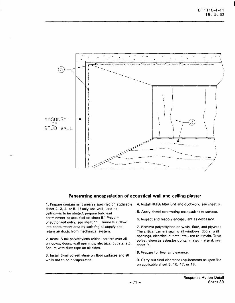
MASONRY-+-. OR
STUD WALL
EP1110-1-11 15 JUL 92
Penetrating encapsulation of acoustical wall and ceiling plaster
1 . Prepare containment area as specified on applicable sheet 2, 3, 4, or 5. (If only one wall-and no ceiling-is to be abated, prepare bulkhead containment as specified on sheet 5.) Prevent unauthorized entry; see sheet 1 1. Eliminate airflow into containment area by isolating all supply and return air ducts from mechanical system.
2. Install 6-mil polyethylene critical barriers over all windows, doors, wall openings, electrical outlets, etc. Secure with duct tape on all sides.
3. Install 6-mil polyethylene on floor surfaces and all walls not to be encapsulated.
4. Install HEPA filter unit and ductwork; see sheet 8.
5. Apply tinted penetrating encapsulant to surface.
6. Inspect and reapply encapsulant as necessary.
7. Remove polyethylene on walls, floor, and plywood. The critical barriers sealing all windows, doors, wall openings, electrical outlets, etc., are to remain. Treat polyethylene as asbestos-contaminated material; see sheet 9.
8. Prepare for final air clearance.
9. Carry out final clearance requirements as specified on applicable sheet 5, 1 6, 1 7, or 1 8.
-71 -Response Action Detail
Sheet 39

MASONRY OR
STUD WALL
EP1110-1-11 15JUL92
i I
Combination encapsulation of acoustical wall and ceiling plaster
1 . Prepare containment area as specified on applicable sheet 2. 3, 4, or 5. (If only one wall-and no ceiling-is to be abated, prepare bulkhead containment as specified on sheet 5.) Prevent unauthorized entry; see sheet 1 1. Eliminate airflow into containment area by isolating all supply and return air ducts from mechanical system.
2. Install 6-mil polyethylene critical barriers over all windows, doors, wall openings, electrical outlets, etc. Secure with duct tape on all sides.
3. Install polyetl)ylene on floor surfaces aod walls not to be encapsulated.
4. Install HEPA filter and ductwork; see sheet 8.
5. Apply tinted penetrating encapsulant to wall and ceiling surface.
6. Inspect and reapply encapsulant as necessary.
7. Apply tinted bridging encapsulant to surface of acoustical wall or ceiling plaster.
8. Inspect and reapply encapsulant as necessary.
9. Remove polyethylene on walls, floor, and plywood. The critical barriers sealing all windows, doors, wall openings, electrical outlets, etc., are to remain. Treat polyethylene as asbestos-contaminated material; see sheet 9.
1 0. Prepare area for final air clearance.
1 1. Carry out final clearance requirements as specified on applicable sheet 5, 16, 17. or 18.
-72-Response Action Detail
Sheet 40

-PLASTER
I I I I I I I ::EJ : : DANGER I I I I I I I I I I I
(
~~-/ ... -...
~ r~~~~==~~~~
fr//
EP 1110-1-11 15 JUL 92
,...___ __ ACOUSTICAL CEILING PLASTER
~-----+--AIRLOCK
Repair of acoustical ceiling or wall plaster
1 . Prepare mini-containment area as specified on sheet 7.
2. Adequately wet mist damaged plaster with amended water, initially and during removal procedure.
3. Remove damaged plaster down to the masonry, using chisel or otl:ler technique. Brush area .to remove remaining residue. Place removed asbestos-containing material in approved containers; see sheet 9. Apply labels; see sheet 14.
4. Repair damaged area bv troweling or otherwise
applying new asbestos-free plaster to damaged areas, matching adjacent surfaces.
5. Apply tinted penetrating encapsulant to repaired surface.
6. Inspect and reapply encapsulant as necessary.
7. Prepare area for final air clearance.
B. Carry out final clearance requirements as specified on sheet 7.
-73-Response Action Detail
Sheet 41

PLASTER
EP1110-1-11 15 JUL 92
Removal of acoustical wall plaster on masonry
1 . Prepare containment area as specified on applicable sheet 2, 3, 4, or 5.
2. Prepare ceiling as directed below:
• Cover light fixture with 6-mil polyethylene. • Protect entire suspended ceiling system with
6-mil polyethylene.
3. Adequately wet mist surface of plaster with amended water, initially and during removal procedures.
4. Remove acoustical plaster from masonry wall by scraping or other technique. Brush, HEPA vacuum,
and wet wipe surface in order to remove remaining dust and residue. Place in approved container; see sheet 9. Apply labels; see sheet 14.
5. Inspect and reclean as necessary. Apply tinted penetrating encapsulant.
6. Inspect and reapply encapsulant as necessary.
7. Prepare area for final air clearance.
8. Carry out final clearance requirements as specified on applicable sheet 5, 16, 17, or 18.
-74-Response Action Detail
Sheet 42

E P 11 1 0-1-1 1 15 JUL 92
ASBESTOS CONTAINING ACOUSTICAL PLASTER
STUDS
DRYWALL POLYETHYLENE
Enclosure of acoustical ceiling plaster, spray-on fireproofing, and thermal insulation
1. Establish work area so that unauthorized entry is prevented; see sheet 1 1. Prepare containment area as specified on sheet 2 1.
2. HEPA vacuum wall and floor surfaces. Aochor studs into adjacent walls, staple 6-mil polyethylene to studs, and seal edges with duct tape.
3. Attach asbestos-free drywall to studs. HEPA vacuum wall and floor surfaces.
4. After completion of abatement work, HEPA vacuum clothing and shoes.
5. Prepare area for final air clearance.
6. Carry out final clearance requirements as specified on sheet 21.
-75-Response Action Detail
Sheet 43

CONCRETE
PLASTER
EP 1110-1-11 15 JUL 92
DUCT
Removal of acoustical ceiling plaster (nonasbestos substrate)
1. Prepare containment area as specified on applicable sheet 2, 3, or 4.
2. Adequately wet mist surface of plaster with amended water, initially and during the removal procedure.
3. Remove acoustical plaster from masonry ceiling by scraping or other techniques. Brush, HEPA vacuum, and wet wipe surface in order to remove remaining
dust and residue. Place in approved container; see sheet 9. Apply labels; see sheet 14.
4. Inspect and reclean area as necessary. Apply tinted penetrating encapsulant.
5. Inspect and reapply encapsulant as necessary.
6. Prepare area for final air clearance.
7. Carry out final clearance requirements as specified on applicable sheet 16, 17. or 18.
-76-Response Action Detail
Sheet 44

MATERIAL
POLYETHYLENE BAG
EP1110-1-11 15 JUL 92
Removal of miscellaneous asbestos-containing materials
1 . Establish work area so that unauthorized entry is prevented; see sheet 11. Prepare containment area as specified on sheet 21.
2. Adequately wet mist materials with amended water. Remove and place in approved container; see sheet 9. Apply labels; see sheet 14.
3. HEPA vacuum and wet wipe area in the immediate vicinity of removed materials.
4. Prepare area for final clearance.
5. Carry out final clearance requirements as specified on sheet 21.
-77-Response Action Detail
Sheet 45

PLASTER
EPlll0-1-11 15 JUL 92
PLASTER
Removal of asbestos decorative paint on plaster
1 . Prepare containment area as specified on applicable sheet 2, 3, 4, or 5.
2. Adequately wet mist surface of plaster with amended water, initially and during removal.
3. Remove all surface-mounted fixtures. Remove all decorative paint on plaster, using chisel and brush or other techniques. Brush, HEPA vacuum, and adequately wet clean surface in order to remove . .
remaining dust and residue. Place in approved container; see sheet 9. Apply labels; see sheet 14.
4. Apply tinted penetrating encapsulant. Inspect and reapply as necessary.
5. Prepare area for final air clearance.
6. Carry out final clearance requirement as specified in applicable sheet 5, 16, 17. or 18.
-78-Response Action Detail
Sheet 46

EP 1110-1-11 15 JUL 92
Removal of light curtain
1. Prepare modified containment area as specified on sheet 21.
2. While curtain is still hanging, spray a mist of removal encapsulant on both sides of curtain. Slowly and carefully lower curtain onto two layers of 6-mil polyethylene, fok1ing the curtain in layers as it is lowered. Wrap top layer of polyethylene, creating a bundle. Seal bundle with duct tape; see sheet 98. Apply labels; see sheet 14.
3. Wrap second layer of polyethylene around bundle and seal with duct tape; see sheet 98. Apply labels; see sheet 14.
4. Prepare area for final air clearance.
5. Carry out clearance requirements as specified on sheet 21.
-79-Response Action Detail
Sheet 47

EP1110-1-11 15 JUL 92
Removal of interior asbestos cement, fiberboard, and drywall panels
1. Prepare containment area as specified on applicable sheet 2, 3, 4, 5, or 6.
2. Adequately wet mist wall panels with amended water or removal encapsulant, initially and during removal.
3. Carefully remove all panels, minimizing breakage. Treat fasteners a~ asbestos-contaminated l'!laterial. Take off any remaining residue on exposed structural surfaces and apply tinted penetrating encapsulant. Inspect and reapply encapsulant as necessary.
4. Separate, stack, and wrap all materials with two layers of 6-mil polyethylene. Seal the joints and ends of each layer with duct tape; see sheet 98. Apply labels; see sheet 14. Place smaller material in approved container; see sheet 98. Apply labels; see sheet 14.
5. Prepare area for final air clearance.
6. Carry out final clearance requirements as specified on applicable sheet 5, 6, 16, 17, or 18.
-80-. Response Action Detail
Sheet 48
I
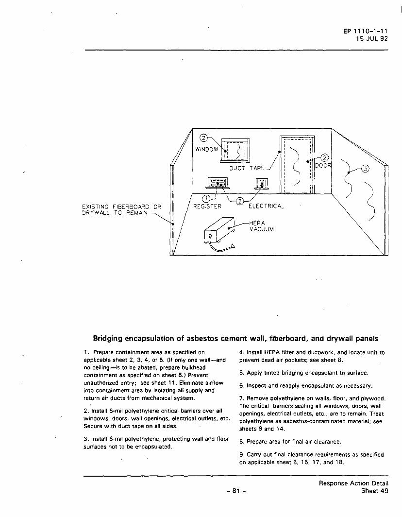
--------.
EP 11 1 0-1-11 15 JUL 92
~--5--; I I I I !_ ____ ,
I I
:~
EXISTING FIBERBOARD OR DRYWALL TO REMAIN
DUCT TAPE
~HEPA ~ VACUUM
Bridging encapsulation of asbestos cement wall, fiberboard, and drywall panels
1 . Prepare containment area as specified on applicable sheet 2, 3, 4, or 5. (If only one wall-and no ceiling-is to be abated, prepare bulkhead containment as specified on sheet 5.) Prevent unauthorized entry; see sheet 1 1 . Eliminate airflow into containment area by isolating all supply and return air ducts from mechanical system.
2. Install 6-mil polyethylene critical barriers over all windows, doors, wall openings, electrical outlets, etc. Secure with duct tape on all sides.
3. Install 6-mil polyethylene, protecting wall and floor surfaces not to be encapsulated.
4. Install HEPA filter and ductwork, and locate unit to prevent dead air pockets; see sheet 8.
5. Apply tinted bridging encapsulant to surface.
6. Inspect and reapply encapsulant as necessary.
1. Remove polyethylene on walls, floor, and plywood. The critical barriers sealing all windows, doors, wall openings, electrical outlets, etc., are to remain. Treat polyethylene as asbestos-contaminated material; see sheets 9 and 1 4.
8. Prepare area for final air clearance.
9. Carry out final clearance requirements as specified on applicable sheet 5, 1 6, 1 7, and 1 8.
-81 -Response Action Detail
Sheet 49

> .....___ 'i:::::::
EP1110-1-11 15 JUL 92
NONCONT AMINATED OUTER MASONRY
0 r r v v
)
INNER CONTAMINATED MASONRY
( (
n > .....___ 'i::::::: ~
Removal of asbestos-contaminated masonry for masonry chimney
1. Prepare containment area as specified on sheet 3 _ (for interior applications) or sheet 7 (for exterior applications).
2. Adequately wet mist inner surface of chimney lining with amended water, initially and during removal procedures.
3. Demolish chimney by first separating outer masonry courses from the inner masonry courses,
using a chisel. HEPA vacuum outer masonry and treat as ordinary construction waste.
4. Break the inner masonry and chimney lining apart. Place in a sealable rigid container; see sheet 9. Apply labels; see sheet 14.
5. Prepare area for final clearance.
6. Carry out final clearance requirements as specified on sheet 17 (interior applications) or sheet 7 (exterior applications).
-82-Response Action Detail
Sheet 50

EP 1110-1-11 15 JUL 92
NONCONT AMINATED SURFACE
PLASTER OR STUCCO
Removal of asbestos-contaminated masonry wall or thermal insulation
1 . Prepare containment area as specified on sheet 6.
2. Adequately wet mist surface of plaster or stucco with amended water, initially and during removal procedure.
3. Demolish masonry wall.
4. Place contaminated masonry into a sealable rigid container; see sheet 9. Apply labels; see sheet 14.
5. Prepare area for final air clearance.
6. Carry out final clearance requirements as specified on sheet 6.
-83-. Response Action Detail
Sheet 51

EP 1110-1-11 15 JUL 92
--- --- ------ ---
Removal of suspended asbestos cement ceiling tile
1 . Prepare containment area as specified on sheet 21 .
2. Adequately wet mist tile surfaces with amended water, initially and during removal.
3. HEPA vacuuf'!l while removing existing_suspended ceiling system, including tile, splines, "T" bars, and wire hangers. Treat all materials as asbestos-contaminated waste. HEPA vacuum and wet wipe surfaces.
4. Separate and stack all materials, and wrap with two layers- of 6-mil polyethylene. Seal the joints and ends of each layer with duct tape; see sheet 98. Apply labels; see sheet 1 4. Place smaller material in approved container; see sheet 98. Apply labels; see sheet 14.
5. Prepare area for final air clearance.
6. Carry out final clearance requirements as specified on sheet 21.
-84-Response Action Detail
Sheet 52

--------------
~
EP1110-1-11 15 JUL 92
I
I
Removal of asbestos cement architectural products
1 . Prepare modified containment area as specified on sheet 21.
2. Adequately mist a removal encapsulant on the top surface of the product. Remove product. HEPA vacuum and wet wipe surface area. Spread two layers of 6-mil polyethylene on floor beside the product. Wrap top layer of polyethylene around the product. Seal all joints and ends with duct tape; see
sheet 98. Apply labels; see sheet 14. Wrap again with second layer of polyethylene in the same manner; see sheet 98. Apply labels; see sheet 1 4.
3. Prepare area for final clearance.
4. Carry out final clearance requirements as specified on sheet 21.
-85-Response Action Detail
Sheet 53

-- -- --
EP1110-1-11 15 JUL 92
---------
Removal of suspended acoustical ceiling tile
1 . Prepare containment area as specified on applicable sheet 2, 3, or 4.
2. Adequately wet mist tile surfaces with amended water, initially and during removal procedures.
3. HEPA vacuum while removing existing suspended ceiling system, including tile, splines, "T" bars, and wire hangers. .Treat all materials as asbestos-contaminated waste. HEPA vacuum and wet wipe surfaces.
4. Separate and stack all materials, and wrap with two layers of 6-mil polyethylene. Wrap top layer of
polyethylene around the product. Seal the joints and ends of each layer with duct tape; see sheet 98. Apply labels; see sheet 1 4. Wrap again with second layer of polyethylene in the same manner; see sheet 98. Apply labels; see sheet 1 4.
5. Prepare area for final air clearance. (If the ceiling is being removed to gain access to other asbestos-containing materials, omit this step until abatement of all asbestos-containing materials is complete).
6. Carry out final clearance requirements specified on sheet 1 6, 17, or 1 8.
-86-Response Action Detail
Sheet 54

EP1110-1-11 15 JUL 92
Removal of glued-on acoustical ceiling and wall tile
1 . Prepare containment area as specified on applicable sheet 2, 3, or 4.
2. Adequately wet mist tile surfaces with amended water, initially and during removal procedures.
3. Remove glued-on tiles, and scrape off remaining glue.
4. Clean, HEPA vacuum, and adequately wet clean.
5. Separate and stack all materials, and wrap with two layers of 6-mil polyethylene. Wrap top layer of polyethylene around ACM. Seal the joints and ends of each layer with duct tape; see sheet 98. Apply labels;
see sheet 14. Wrap again with second layer of polyethylene in the same manner; see sheet 98. Apply labels; see sheet 14. Place smaller material in approved container; see sheet 98. Apply labels; see sheet 14.
6. Inspect and reclean area as necessary.
7. Apply tinted penetrating encapsulant. Inspect and reapply as necessary.
8. Prepare area for final clearance.
9. Carry out final clearance requirements specified on applicable sheet 16, 17, or 18.
-87-Response Action Detail
Sheet 55

EP1110-1-11 15 JUL 92
Repair of vinyl asbestos tile adhered to concrete floor system
1. Prepare work area; see sheet 21. Prevent unauthorized entry; see sheet 1 1.
2. Remove damaged asbestos tile. Place into an approved container; see sheet 9. Apply labels; see sheet 14.
3. HEPA vacuum and adequately wet clean.
4. Inspect.
5. Install new tile.
6. Prepare area for final clearance.
7. Carry out final clearance requirements specified on sheet 21.
-88-Response Action Detail
Sheet 56

• 0 • 0
EP 1110-1-11 15 JUL 92
Removal of vinyl asbestos tile adhered to concrete floor system by asbestos-containing adhesive
1. Prepare containment area as specified on sheet 21. _ approved container; see sheet 9. Apply labels; see NOTE: Where full containment area is required, follow sheet 14. instructions on sheet 4, except omit polyethylene on floor.
2. Lightly flood asbestos tile with amended water, and let soak for 48 hours. Remove asbestos tile-and adhesive while they are wet in order to prevent asbestos fiber release. Place tile and adhesive into an
3. Clean, HEPA vacuum, and wet wipe all surfaces.
4. Inspect and reclean area as necessary.
5. Prepare area for final air clearance.
6. Carry out final clearance requirements as specified on applicable sheet 18 or 21.
-89-Response Action Detail
Sheet 57

0 • 0 0 0
0
0
(
• 0 • 0 •
0
EP 1110-1-11 15 JUL 92
Removal of vinyl asbestos tile adhered to concrete floor system by asbestos-free adhesive
1 . Prepare containment area as specified on sheet 21. NOTE: Where full containment area is required, follow instructions on sheet 4, except omit polyethylene on floor.
2. Lightly flood asbestos tile, and soak for 48 hours. Remove asbestos tile and adhesive while they are wet in order to prevent asbestos fiber release. Place tile and adhesive into an approved container; see sheet 9. Apply labels; see sheet 1 4.
3. Clean, HEPA vacuum, and adequately wet clean all surfaces.
4. Inspect and reclean area as necessary.
5. Prepare area for final air clearance.
6. Carry out final clearance requirements as specified on applicable sheet 1 8 or 21 .
-90-Response Action Detail
Sheet 58

• 0 •
E P 11 1 0-1-11 15 JUL 92
USE THIS DETAIL ONLY FCR
- SMALL SCALE PROJECiS - GROUND FLOOR APPLIC~~=J~S
Removal of vinyl asbestos tile and chemical dissolution of asbestos-containing adhesives on concrete floor system
1 . Prepare containment area as specified on sheet 4.
2. Lightly flood asbestos tile, and soak for 48 hours. Remove asbestos tile and adhesive while they are wet in order to prevent asbestos fiber release. Place tile and adhesive into an approved container; see sheet 9. Apply labels; see sbeet 14.
3. Before removing adhesive, increase ventilation rate to 1 0 air changes per hour. Air must be exhausted outside building.
4. Apply liquid adhesive remover. As soon as the adhesive is soft enough to scrape, remove and put into approved -container; see sheet 9. Apply labels; see sheet 14.
5. Prepare area for final air clearance.
6. Carry out final clearance requirements as specified on sheet 18.
-91 -Response Action Detail
Sheet 59

EP 111 0-1-11 15 JUL 92
Repair of vinyl asbestos tile adhered to wood floor system by asbestos-containing adhesive
1. Prepare work area; see sheet 21. Prevent unauthorized entry; see sheet 11.
2. Adequately mist-and remove damaged asbestos tile and adhesive. Place tile and adhesive into an approved container; see sheet 9. Apply labels; see sheet 14.
3. HEPA vacuum and wet wipe area.
4. Install new tile.
5. Inspect.
6. Prepare area for final clearance.
7. Carry out final clearance requirements specified on sheet 21.
-92-Response Action Detail
Sheet 60

EP1110-1-11 15 JUL 92
Removal of vinyl asbestos tile adhered to wood floor system by asbestos-containing adhesive
1 . Prepare containment area as specified on sheet 21 • except omit polyethylene on floor. NOTE: Where full containment is required, follow instructions on sheet 4.
2. Where wood flooring is to remain, adequately wet and remove asbestos tile and adhesive in order to prevent asbestos fiber release. Place tile and adhesive into an approved container; see sheet 9. Apply labels; see sheet 1 4. Note: Where wood flooring i~ to be removed, adequately wet and remove existing wood flooring. Treat as asbestos-contaminated material. Spread a plastic sheet on the floor, and stack removed wood flooring onto two layers of 6-mil polyethylene.
Wrap each polyethylene layer around the stack, sealing all joints and edges with duct tape; see sheet 9. Apply labels to stack; see sheet 1 4. Smaller material will be placed in approved container; see sheet 9. Apply labels; see sheet 1 4.
3. Clean, HEPA vacuum, and adequately wet clean all surfaces.
4. Inspect and reclean area as necessary.
5. Prepare area for final air clearance.
6. Carry out final clearance requirements specified in applicable sheet 18 or 21.
-93-Response Action Detail
Sheet 61

EP1110-1-11 15 JUL 92
Removal of vinyl asbestos tile adhered to wood floor system by asbestos-free adhesive
1. Prepare containment area as specified on sheet 21. NOTE: Where full containment is required, follow instructions on sheet 4, except omit polyethylene on floor.
2. Adequately wet and remove asbestos tile and adhesive while they are wet in order to prevent asbestos fiber release. Place tile and adhesive into an approved container; see sheet 9. Apply labels; see sheet 14.
3. Clean, HEPA vacuum, and wet wipe all surfaces.
4. Inspect and reclean area as necessary.
5. Prepare area for final air clearance.
6. Carry out final clearance requirements specified on applicable sheet 1 8 or 21.
-94-Response Action Detail
Sheet 62

EP1110-1-11 15 JUL 92
Removal of sheet-flooring adhered to wood floor system
1. Prepare containment area as specified on sheet 21. NOTE: Where full containment is required, follow instructions on sheet 4, except omit polyethylene on floor.
2. Mist exposed surfaces with amended water just before sheet flooring is removed. Remove flooring in manageable pieces and place on two layers of 6-mil polyethylene. Wrap each layer of polyethylene around the stack, sealing all joints and edges with duct tape; see sheet 9. Apply labels; see sheet 14. Place smaller
material in approved container; see sheet 9. Apply labels; see sheet 1 4.
3. Clean, HEPA vacuum, and adequately wet clean all surfaces.
4. Inspect and reclean area as necessary.
5. Prepare area for final air clearance.
6. Carry out final clearance requirements as specified on applicable sheet 18 or 21.
-95-Response Action Detail
Sheet 63

EP 1110-1-11 15 JUL 92
Removal of sheet-flooring adhered to concrete floor system by asbestos-containing adhesive
1. Prepare containment area as specified on sheet 21. NOTE: Where full containment is required, follow instructions on sheet 4, except omit polyethylene on floor.
2. Mist exposed surfaces with amended water just before sheet flooring is removed. Remove flooring in manageable pieces and place on two layers of 6-mil polyethylene. Wrap each layer of polyethylene around the stack, sealing all joints and edges with duct tape; see sheet 9. Apply labels; see sheet 14. Place smaller material in approved container; see sheet 9. Apply labels; see sheet 1 4.
3. Remove remaining adhesive down to bare concrete. Place in approved container; see sheet 9. Apply labels; see sheet 1 4.
4. Clean, HEPA vacuum, and wet wipe all surfaces.
5. Inspect and reclean area as necessary.
6. Prepare area for final air clearance.
7. Carry out final clearance requirements specified on applicable sheet 1 8 or 21.
-96-Response Action Detail
Sheet 64

EP1110-1-11 15 JUL 92
I I I I I I I I I I I 1 1 1 I 1
Removal of carpeting (asbestos-containing or -contaminated)
1 . Prepare modified containment area as specified on sheet 21.
2. Adequately mist a removal encapsulant on the top surface of the carpet.
3. Carefully roll the carpet into a tight cylin_der. As the carpet is being rolled, mist the newly exposed side.
4. Spread out two layers of 6-mil polyethylene on the floor beside the cylinder and carefully roll the carpet onto the polyethylene.
5. Wrap each layer of the polyethylene around the cylinder. Seal all joints and ends with duct tape; see sheet 9. Apply labels; see sheet 14.
6. Clean, HEPA vacuum, and adequately wet clean surfaces.
7. Prepare for final air clearance.
8. Carry out final clearance requirements as specified on sheet 21.
-97-Response Action Detail
Sheet 65

r----, r----, I I
r---, I I I I
I I I -I I -I
r---., ,----1 I I I I I I I I
r - I I--
I I I I
-I I I I -
- I I I I
- I I _ I . I
I I I -I
EP1110-1-11 15 JUL 92
r--1
I
EXISTING ACM
EXISTING BEAMS AND DECKING, WITH ASBESTOS FIREPROOFING OR THERMAL SURF ACE INSULATION
Encasement of fireproofing or thermal insulation of beams and decking
1 . Prepare containment area as specified on applicable 4. Inspect. sheet 2, 3, or 4.
2. Apply foam sealer to existing asbestos fireproofing in accordance with manufacturer's recommendations.
3. Spray on polymer shell finish.
5. Prepare area for final clearance.
6. Carry out final clearance requirements specified on applicable sheet 16, 17, or 18.
-98-Response Action Detail
Sheet 66

I 1
,-----, I
I I
/ I I
I I I
I
I I I I I I I I I I •""'-""-"'-"'-_,....,_,.,_v_v_v_"'"_ "'--""-""-""-"'-"'-""-"'-_-v_v_}
I I I I I I ,-----------------------~ I 1~"-"''V"VVV~V'v"A-"'"-"''V'V~ I I
I I I I I I
I / I I I I I I I
I ~--_j
EXISTING COLUMN WITH ASBESTOS FIREPROOFING OR
INSULATION THERMAL SURF ACE
EP 1110-1-11 15 JUL 92
EXISTING ACM
Encasement of fireproofing or thermal insulation on columns
1 . Prepare containment area as specified on applicable 5. Inspect and reapply polymer shell finish as sheet 2, 3, or 4. necessary.
2. Apply foam sealer to existing asbestos fireproofing 6. Prepare area for final air clearance. in accordance with manufacturer's recommendations.
7. Carry out final clearance requirements as specified 3. Inspect and reapply as necessary. on applicable sheet 16, 17, or 18.
4. Spray on polymer shell finish.
-99-Response Action Detail
Sheet 67

EP1110-1-11 15 JUL 92
Removal of fireproofing or thermal surface insulation
1 . Prepare containment area as specified on applicable sheet 2, 3, or 4.
2. Adequately wet mist surface of insulation/fireproofing with amended water, initially and during removal procedures.
3. Remove sprayed-on fireproofing from all structural members. Brush, HEPA vacuum, and wet wipe exposed steel surfaces in order to remove residual material. Place removed asbestos-containing material
in approved containers; see sheet 9. Apply labels; see sheet 14.
4. Inspect and reclean area as necessary.
5. Apply tinted penetrating encapsulant. Inspect and reapply encapsulant as necessary.
6. Prepare area for final air clearance.
7. Carry out final clearance requirements as specified on applicable sheet 16, 17, or 18.
-100-Response Action Detail
Sheet 68

-----------~
3
EXISTING ACM
EP1110-1-11 15 JUL 92
Encasement of acoustical ceiling insulation
1. Prepare containment area as specified on applicable 4. Spray on polymer shell finish. sheet 2, 3, or 4.
2. Install encasement supports per manufacturer's recommendations. Apply foam sealer to existing acoustical ceiling insulation.
3. Inspect.
5. Inspect.
6. Prepare area for final air clearance.
7. Carry out final clearance requirements as specified on applicable sheet 16, 17, or 18.
- 101 -Response Action Detail
Sheet 69

---------------------~ I I I I I I I I
\ \
I I I I I I I I I I I I I I
~-----~
EP1110-1-11 15 JUL 92
Removal of acoustical ceiling insulation
1 . Prepare containment area as specified on applicable sheet 2, 3, or 4.
2. Adequately wet mist surface of acoustical ceiling insulation with amended water, initially and during abatement procedures.
3. Remove all surface-mounted fixtures. Remove insulation on structural substrate. Clean, HEPA vacuum, and adequately wet clean surface in order to remove remaining residue.
4. Inspect and reclean area as necessary.
5. Apply tinted penetrating encapsulant. Inspect and reapply encapsulant as necessary.
6. Prepare area for final air clearance.
7. Carry out final clearance requirements as specified on applicable sheet 16, 17, or 18.
- 102-Response Action Detail
Sheet 70

. . . .. . . . . . . . . . .
. . . . . . .
EP 1110-1-11 15 JUL 92
NEW CONCREIE FLOOR OVER ASBESTOS CONTAMINATED SOIL
Enclosing asbesto~-contaminated soil
1 . Prepare mini-containment area as specified on sheet 7. Install HEPA-filtered air exhauster in a location that will provide air movement through work area. Adequately wet mist soil floor with amended water. Gather loo-se debris and place in app-roved container; see sheet 9. Apply labels; see sheet 14.
2. Place 6-mil polyethylene on top of soil floor, and cast a new 2-inch concrete floor.
3. Apply tinted penetrating encapsulant to wall and ceiling surfaces, using airless sprayer.
4. Prepare area for final clearance.
5. Carry out final clearance requirements as specified on sheet 7.
-103-Response Action Detail
Sheet 71

. . .. . . • I • • . . .
. . . . . . . .
. . •.
. .
EP1110-1-11 15 JUL 92
ASBESTOS CONT AMINAT~C SOIL
Penetrating encapsulation of asbestos-contaminated soil
1 . Prepare mini-containment area as specified on sheet 7. Install HEPA-filtered air exhauster in a location that will provide air movement through work area. Adequately_wet mist soil floor and d~bris with amended water. Gather loose debris and place in approved container; see sheet 9. Apply labels; see sheet 14.
2. Apply tinted penetrating encapsulant to walls and
ceilings and the accepted soil encapsulation system to the soil.
3. Inspect and reapply encapsulant as necessary.
4. Prepare area for final clearance.
5. Carry out final clearance requirements as specified on sheet 7.
-104-Response Action Detail
Sheet 72

... . . . . . . . .
EP 1110-1-11 15 JUL 92
ASBESTOS CONTAMINATED SOIL
Removal of asbestos-contaminated soil
1. Prepare mini-containment area as specified on sheet 7. Install HEPA·filtered air exhauster in a
location that will provide air movement through work area. Adequately wet mist soil floor and debris with amended water. Gather loose debris and place in approved container; see sheet 9. Apply labels, see sheet 14.
2. Gently loosen the top 2 inches of soil and remove, using an asbestos_ HEPA-filtered power vacuum collection and removal system; see sheet 26. Collect material into approved containers; see sheet 9. Apply labels; see sheet 14.
3. After all soil has been removed, use vacuum collection and removal system to vacuum walls and ceilings.
4. Inspect and reclean area as necessary.
5. Apply tinted penetrating encapsulant to wall and ceiling surfaces, and apply an approved soil encapsulation system to the soil. Inspect wall and ceiling and reapply encapsulant as necessary.
6. Prepare area for final clearance.
7. Carry out final clearance requirements as specified on sheet 7.
- 105-Response Action Detail
Sheet 73

BUlL T-UP\ ROOFING \
INSULATIO
STEEL OR CONCRETE ROOF DECK
EP 1110-1-11 15 JUL 92
CAP FLASHING
METAL FLASHING
Removal of built-up roofing and flashing
1. No containment area is required. Establish boundaries of asbestos-regulated work area so that unauthorized entry is prevented; see sheet 1 1. Provide personal protection and decontamination facilities as specified in contractor's asbestos hazard abatement plan.
2. Remove accumulated debris.
3. Adequately wet mist flashing and built-up roofing, initially and during removal procedures. Remove flashing and built-up roofing.
4. Dispose of all materials by carefully sliding them down an enclosed chute into an enclosed Dumpster or truck that is lined with two layers of 6-mil polyethylene. When the Dumpster or truck is filled,
fold the polyethylene edges over each other and seal with duct tape; see sheet 9 tor leak-tight wrapping. Apply labels; see sheet 14.
5. Clean and HEPA vacuum roof.
6. Inspect and reclean area as necessary.
7. Apply tinted penetrating encapsulant to exposed roof deck, using an airless sprayer. Inspect and reapply encapsulant as necessary.
8. Prepare area for final clearance.
9. Contractor and contracting officer will certify visual inspection of work area on sheet 19, Certification of Final Cleaning and Visual Inspection.
-106-Response Action Detail
Sheet 74

SHINGlES
ROOFING FELT----...
ROOF DECK
EP 1110-1-11 15JUL92
ROOF JOISTS
Removal of roof, shingles, and underlay
1 . No containment area is required. Establish boundaries of asbestos-regulated work area so that unauthorized entry-is prevented, and install warning signs; see sheet 1 1 . Provide personal protection and decontamination facilities as specified in contractor's asbestos hazard abatement plan.
2. Remove shingles, roofing felt, nails, and debris, using wet removal technique.
3. Dispose of all materials by carefully sliding them down an enclosed chute into an enclosed Dumpster or truck that is lined with two layers of 6-mil polyethylene. When Dumpster or truck is filled, fold
the polyethylene edges over each other and seal with duct tape; see sheet 9. Apply labels; see sheet 14.
4. Clean and HEPA vacuum roof.
5. Inspect and reclean area as necessary.
6. Apply tinted penetrating encapsulant to exposed roof deck, using an airless sprayer.
7. Prepare area for final clearance.
8. Contractor and contracting officer will certify visual inspection of work area on c;heet 19, Certification of Final Cleaning and Visual Inspection.
- 107-Response Action Detail
Sheet 75

EXISTING MASONRY WALL TO REMAIN
STUCCO
)
)
)
)
EP 1110-1-11 15 JUL 92
3
Bridging encapsulation of exterior asbestos stucco
1. Establish boundaries of asbestos-regulated work area so that unauthorized entry is prevented; see sheet 11 . Provide personal protection and decontamination fa~cilities as specified in contractor's asbestos hazard abatement plan.
2. Apply tinted bridging encapsulant to surface of stucco.
3. Inspect and reapply encapsulant as necessary.
4. Contractor and contracting officer will certify visual inspection of work area on sheet 19, Certification of Anal Cleaning and Visual Inspection.
-108-Response Action Detail
Sheet 76

EXISTING MASONRY WALL
STUCCO
EP 1110-1-11 15 JUL 92
Bridging encapsulation of interior asbestos stucco
1. Prepare containment as specified on applicable sheet 2, 3, 4, or 5. (If only one wall-and no ceiling-is to be abated, prepare bulkhead containment area as specified on sheet 5.) Prevent unauthorized entry; see sheet 1 1. Eliminate airflow into containment area by isolating all supply and air ducts from mechanical system.
2. Install 6-mil polyethylene critical barriers over all windows, doors, wall openings, electrical outlets, etc. Secure with duct tape on all sides.
3. Install 6-mil polyethylene on floor surfaces and walls not to be encapsulated. If only one wall is included, prepare bulkhead containment area as specified on sheet 5.
4. Install HEPA filter unit and ductwork; see sheet 8.
5. Apply tinted bridging encapsulant to surface of asbestos stucco.
6. Inspect and reapply encapsulant as necessary.
7. Remove polyethylene on walls and floor. The critical barriers sealing all windows, doors, wall openings, electrical outlets, etc., are to remain. Treat polyethylene as asbestos-contaminated material; see sheet 9.
8. Prepare area for final air clearance.
9. Carry out final clearance requirements as specified on applicable sheet 5, 16, 17, or 18.
- 109-Response Action Detail
Sheet 77

EXISTING MASONRY WALL TO REMAIN
STUCCO
)
)
)
)
)
EP1110-1-11 15 JUL 92
Repair of interior asbestos stucco
1 . Prepare mini-containment area as specified on sheet 7.
2. Adequately wet mist stucco with amended water, initially and during removal procedure. Remove damaged stucco and place in approved container; see sheet 9. Apply lab,els; see sheet 14.
3. Apply tinted penetrating encapsulant. Inspect and reapply as necessary.
- 4. Apply new asbestos-free stucco to damaged area, matching adjacent stucco surfaces.
5. Inspect.
6. Prepare area for final air clearance.
1. Carry out final clearance requirements as specified on sheet 7.
- 110-Response Action Detail
Sheet 78

)
)
EXISTING MASONRY WALL TO REMAIN
STUCCO
l
) l
)
EP 1110-1-11 15 JUL 92
Removal of exterior asbestos stucco
1 . Prepare containment area as specified in applicable 4. Inspect and reclean area as necessary. sheet 5 or 7.
2. Remove stucco attached to masonry. Use adequate wet removal techniques, initially and during removal procedures. Brush, HEPA vacuum, and adequately wet clean area in order to remove residue.
3. Dispose of asbestos stucco in approved containers; see sheet 9. Apply labels; see sheet 14.
5. Apply tinted penetrating encapsulant to exposed masonry.
6. Inspect and reapply encapsulant as necessary.
7. Prepare area for final clearance.
8. Carry out final clearance requirements as specified on applicable sheet 5 or 7.
- 111 -Response Action Detail
Sheet 79

)
)
EXISTING MASONRY WALL TO REMAIN
STUCCO
)
l
) l
)
EP 1110-1-11 15 JUL 92
Repair of exterior asbestos stucco
1. No containment area is required. Establish boundaries of asbestos-regulated work area so that unauthorized entry is prevented; see sheet 11. Place two layers of polyethylene sheeting on the ground in order ~o collect debris.
2. Wet mist stucco with amended water, initially and during removal procedure. Carefully remove damaged stucco and place fn approved containers; se-e sheet 9. Apply labels; see sheet 14.
3. Apply tinted penetrating encapsulant. Inspect and reapply as neces~ry.
4. Apply new asbestos-free stucco to damaged area, matching adjacent stucco surfaces.
5. Fold each layer of polyethylene sheeting inward, and seal all eages with duct tape; see sheet 9. Apply labels; see sheet 14. Treat as asbestos-contaminated material.
6. Prepare area for final clearance.
7. Contractor and contracting officer will certify visual inspection of work area on sheet 19, Certification of Final Cleaning and Visual Inspection.
- 112-Response Action Detail
Sheet 80

~
EP 1110-1-11 15 JUL 92
1111 11111111111 111111 m11 11111111111 11111111111 11111111111
1111111111 11111111111
..
11111111111 II II
II II Ill!' II IIIII !Ill I !II 11111111111
11111111111 11111111111 11111111111 II II
II II 11111111111 11111111111 11111111111 11111111111 11111111111
Removal of asbestos cement siding
1. No containment area is required. Establish boundaries of asbestos-regulated work area so that unauthorized entry is prevented; see sheet 11. Provide personal protection and decontamination facilities as specified in contractor's asbestos hazard abatement plan.
2. Wet mist siding with amended water, initially and during removal procedures.
3. Anchor 1 0-mil polyethylene sheeting below work area. Remove siding in a manner that will prevent crumbling, pulverizing, or reducing to powder during the removal procedure. NOTE: Normal breakage does not constitute crumbling, pulverizing, or reducing to powder.
4. Clean and HEPA vacuum all surfaces.
5. Inspect and reclean area as necessary.
6. Place all materials in Dumpster or other transport container lined with two layers of 6-mil polyethylene. Seal the joints and ends of each layer with duct tape; see sheet 9. Apply labels; see sheet 14. Other containers may be used; see sheet 9. Apply labels; see sheet 14.
7. Prepare area for final clearance.
8. Contractor and contracting officer will certif•t visual inspection of work area on sheet 19, Certification of Final Cleaning and Visual Inspection.
- 113-Response Action Detail
Sheet 81

EP 1110-1-11 15 JUL 92
STRUCTURAL SUPPOR7
Removal of asbestos cement roofing
1. No containment area is required. Establish boundaries of asbestos-regulated work area so that unauthorized entry is prevented; see sheet 1 1. Provide personal protection and decontamination facilities as specified in contractor's asbestos hazard abatement plan.
2. Wet mist the top surface of the roofing with ammended water, initially and during removal procedures. Care_fully remove roofing in a r::nanner that will prevent crumbling, pulverizing, or reducing to powder during the removal procedure. NOTE: Normal breakage does not constitute crumbling, pulverizing, or reducing to powder.
3. Place all materials in Dumpster or other transport container lined with two layers of 6-mil polyethylene. Seal the joints and ends of each layer with duct tape; see sheet 9. Apply labels; see sheet 14. Other containers may be used; see sheet 9. Apply labels; see sheet 1 4.
4. Prepare area for final clearance.
5. Cqntractor and contracting officer will certify visual inspection of work area on sheet 19, Certification of Rna/ Cleaning and Visual Inspection.
- 114-Response Action Detail
Sheet 82

STEEL ANGL EDGE FORM
EP 1110-1-11 15 JUL 92
~~-CORRUGATED ASBESTOS CEMENT CONCRETE FORM
Removal of asbestos-containing walkway cover
1. No containment area is required. Establish boundaries of asbestos-regulated work area so that so that unauthorized entry is prevented; sheet 11. Provide personal protective equipment and decontamination facilities as specified in the contractor's asbestos hazard abatement plan.
2. Install temporary supports at midpoint between existing columns.
3. Support walkway-cover slab with forklift, crane, or other approved lif~ing device ..
4. Saw cut through concrete no deeper than the concrete cover over the corrugated asbestos cement form.
5. Burn through steel side angles and pipe columns.
6. Lift slab and place on truck bed lined with two layers of 6-mil polyethylene sheeting. Seal the joints and ends of each layer with duct tape; see sheet 9. Apply labels; see sheet 14. Treat as asbestos-contaminated construction waste, keeping walkway-cover slab intact. Secure slab to truck bed and cover with tarp. Gather any loose debris lying on ground and place in approved container; see sheet 9. Apply labels; see sheet 1 4. Prepare area for final clearance.
7. Contractor and contracting officer will certify visual inspection of work area on sheet 19, Certification of Final Cleaning and Visual Inspection.
-115-Response Action Detail
Sheet 83
I

! I
i I ' I I
,.. '"'
I I 1 I I I
I I
I I
EP1110-1-11 15 JUL 92
Removal of asbestos-contaminated metal siding
1. Demolish interior of Quonset hut, including wall surfaces, electrical services, etc. Treat as ordinary construction waste.
2. No containment area is required. Establish boundaries of work area so that unauthorized entry is prevented; see sheet 11. Provide personal protection and decontamination facilities as specified in the contractor's asbestos hazard abatement plan.
3. Anchor 1 0-mil polyethylene sheeting below work area. Adequately wet mist exterior siding and scrape off loose paint. Place paint chips and debris in approved contai':ler; see sheet 9. Apply la~els; see sheet 14.
4. Apply tinted penetrating encapsulant to exterior surface of siding. Let dry.
5. From the inside of the Quonset hut, cut metal fasteners as close to metal siding as possible. With crow bar, carefully pry apart the abutting corrugated metal sheeting. Place disassembled sheets on a truck bed lined with two layers of 6-mil polyethylene sheeting. Seal the joints and ends of each layer with duct .tape; see sheet 9. Apply labels; see sheet 1 4. Treat as asbestos-contaminated construction waste.
6. Gather contaminated 1 0-mil polyethylene sheeting and any loose debris lying on ground. Place in approved container; see sheet 9. Apply labels; see sheet 14.
7. Prepare area for final clearance.
8. Contractor and contracting officer will certify visual inspection of work area on sheet 19, Certification of Final Cleaning and Visual Inspection.
- 116-Response Action Detail
Sheet 84

EP 1110-1-11 15 JUL 92
ASBESTOS CEMENT SUN SCREEN LOUVERS
~ROOF DUCT TAPE
Removal of asbestos cement sunscreen louvers
1. No enclosed containment area is required. Establish boundaries of asbestos regulated work so that . unauthorized entry is prevented; see sheet 1 1 . Provide personal protection and decontamination facilities as specified in contractor's asbestos hazard abatement plan.
2. Install 6-mil polyethylene critical barrier over inside face of window and frame. Seal with duct tape. Anchor 1 0-mil polyethylene sheeting below work area.
breakage occurs, place in approved containers per step 3 above. If slats can be removed intact, stack and wrap with two layers of 6-mil polyethylene. Seal the joints and ends with duct tape; see sheet 9. Apply labels; see sheet 1 4.
6. Mist the supporting straps with a removal encapsulant and remove. Treat as asbestos-contaminated waste. Dispose of per step 3 above.
7. HEPA vacuum roof, windows, jambs, and all 3. Clean up roof debris from broken asbestos cement sunscreen louvers. Treat as asbestos-containing material. Place debris in approved containers; see sheet 9. Apply labels; see sheet 14.
- adjacent surfaces as each work area is completed.
4. Place [0.8-inl [20-mmJ plywood sheets on roof or scaffolding adjacent to work area.
5. Adequately mist a removal encapsulant on all accessible louver surfaces, initially and during removal procedures. Gently remove each louver slat by disconnecting from supporting metal straps. If
8. Prepare area for final clearance.
9. Contractor and contracting officer will certify visual inspection of work area on sheet 19, Certification of Rna/ Cleaning and Visual Inspection.
10. Upon instructions from the contracting officer, remove all critical barriers and plywood. Treat as asbestos-contaminated waste per step 3 above.
-117-Response Action Detail
Sheet 85
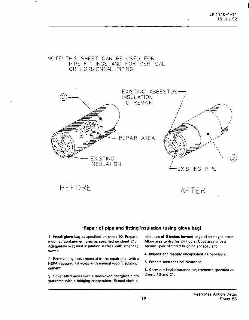
EP 1110-1-11 15 JUL 92
NOTE: THIS SHEET CAN BE USED FOR PIPE FITTINGS AND FOR VERTICAL OR HORIZONTAL PIPING.
EXISTING ASBESTOS INSULATION TO REMAIN
~~---EXISTING INSULATION
BEFORE
EXISTING PIPE
AFTER
·-Repair of pipe and fitting insulation (using glove bag)
1 . Install glove bag as specified on sheet 1 0. Prepare . modified containment area as specified on sheet 21 . Adequately wet mist insulation surface with amended water.
2. Remove any loose material in the repair area with a HEPA vacuum. Fifi voids with mineral wool-insulating cement.
3. Cover filled areas with a nonwoven fiberglass cloth saturated with a bridging encapsulant. Extend cloth a
minimum of 6 inches beyond edge of damaged areas. Allow area to dry for 24 hours. Coat area with a second layer of tinted bridging encapsulant.
4. Inspect and reapply encapsulant as necessary.
5. Prepare area for final clearance.
6. Carry out final clearance requirements specified on sheets 10 and 21.
- 118-Response Action Detail
Sheet 86

EXISTING PIPE
HANGER SYSTEM
JACKETING
EP 1110-1-11 15 JUL 92
JOINT STRAP
NOTE: THIS SHEET CAN BE USED FOR VERTICAL OR HORIZONTAL PIPING.
Removal of pipe insulation (using glove bag)
1. Install glove bag as specified on sheet 1 0. Prepare modified containment area as specified on sheet 21 . Adequately wet mist insulation surface with amended water, initially and during removal.
2. Remove jacketing and asbestos pipe insulation from pipe and hanger to within 2 inches of inside_ edges of glove bag.
3. Clean exposed surfaces by spraying with amended water and brushing.
4. Inspect and reclean as necessary.
5. Spray a tinted penetrating encapsulant on pipe and exposed ends of insulation.
6. Inspect piping and reapply encapsulant as necessary.
7. Prepare area for final air cleara{lce.
8. Carry out final clearance requirements specified on sheets 10 and 21.
-119-Response Action Detail
Sheet 87

EXISTING PIPE
NOTE: THIS SHEET CAN BE USED FOR PIPE FITTINGS AND FOR VERTICAL OR HORIZONTAL PIPING.
HANGER SYSTEM
JACKETING
EP1110-1-11 15 JUL 92
JOINT STRAP
Removal of horizontal pipe insulation (using containment area)
1. Prepare containment area as specified on applicable sheet 2, 3, or 4.
2. Adequately wet mist insulation surface with amended water, initially and during removal. Remove jacketing and insulation from pipe and hanger system.
3. Clean exposed surfaces by spraying with amended water and brushing.
4. Inspect and reclean as necessary.
5. Spray a tinted penetrating encapsulant on pipe and exposed ends of insulation.
6. Inspect piping and reapply encapsulant as necessary.
7. Prepare area for final air clearance.
8. Carry out final clearance requirements specified on applicable sheet 16, 17, or 18.
-120-Response Action Detail
Sheet 88

EXISTING PIP
JACKETING
EXISTING INSULATION
EP1110-1-11 15JUL92
Removal of pipe insulation (using mini-containment area)
1 . Prepare mini-containment area as specified on sheet 7.
2. Adequately wet mist insulation surface with amended water, initially and during removal. Remove jacketing and insulation from pipe and hanger system.
3. Clean exposed surfaces by spraying with amended water and brushing.
4. Inspect and reclean area as necessary.
5. Spray a tinted penetrating encapsulant on pipe and exposed ends of insulation. Inspect and reapply as necessary.
6. Prepare area for final clearance.
7. Carry out final clearance requirements specified on sheet 7.
- 121 -Response Action Detail
Sheet 89

EXISTING BOILER BREECHING OR STORAGE TANK
EP1110-1-11 15 JUL 92
2
EXISTING INSULATION
SECTIONAL VIEW
Encasement of storage tank or boiler breaching
1 . Prepare modified containment area as specified on sheet 21. Install HEPA filter unit and ductwork; see sheet 8.
2. Apply foam sealer to existing insulation.
3. Inspect and reapply sealer as necessary.
4. Spray on polymer shell finish.
5. Inspect.
6. Prepare area for final air clearance.
1. Carry out final clearance requirements specified on sheet 21.
-122-Response Action Detail
Sheet 90

EXISTING BREECHING OR STORAGE TANK
EP1110-1-11 15 JUL 92
EXISTING INSULAT 10i'\
SECTIONAL VIEW
Bridging encapsulation of storage tank and boiler breaching
1 . Prepare modified containment area as specified on sheet 21. Install HEPA filter unit and ductwork; see sheet 8.
2. Apply tinted bridging encapsulant to surface of insulation.
3. Inspect and reapply encapsulant as necessary.
4. Prepare area for final air clearance.
5. Carry out final clearance requirements as specified on sheet 21.
-123-Response Action Detail
Sheet 91

[6 IN.J [15 CMJ t
·--------
---------
~
cV
Vol .. . . . .. ~· ~· . io" . (
<P . . ~
~ v I•
EP 1110-1-11 15 JUL 92
EXISTING STORAGE TANK OR BOILER BREECHING
EXISTING INSULATION
SECTIONAL VIEW
Repair of storage tank and boiler breaching
1 . Prepare mini-containment area as specified on damaged areas. Allow area to dry for 24 hours. Coat sheet 7. Adequately wet mist insulation with amended - area with a second layer of tinted bridging water. encapsulant.
2. Remove any loose material in the repair area with a HEPA vacuum. Fill voids with mineral woof insulating cement.
3. Cover filled areas with a nonwoven fiberglass cloth saturated with a bridging encapsulant. Extend cloth a minimum of [6 in) [1 5 em) beyond the edge of
4. Inspect and reapply encapsulant as necssary.
5. Prepare area for final air clearance.
6. Carry out final clearance requirements specified on sheet 7.
- 124-Response Action Detail
Sheet 92

2
~XIST!NG BOILER BREECH JR STORAGE TANK
EP 1110-1-11 15 JUL 92
SECTIONAL VIEW
Removal of storage tank and boiler breeching insulation
1 . Prepare containment areas as specified on applicable sheet 2, 3, or 4.
2. Adequately wet mist surface with amended water, initially and during removal. Remove insulation, including reinforcing fabric, mesh, steel bands or wire, and jacketing. Plac_e in approved containers; _see sheet 9. Apply labels; see sheet 14.
3. Clean exposed surfaces by spraying with amended water and brushing, HEPA vacuuming, and adequately wet cleaning all surfaces.
4. Inspect and reclean area as necessary.
5. Spray a tinted penetrating encapsulant. Inspect and reapply as necessary.
6. Prepare area for final air clearance.
7. Carry out final clearance requirements specified on applicable sheet 16, 17, or 18.
- 125-Response Action Detail
Sheet 93
I

EP1110-1-11 15 JUL 92
MITERED SEGMENTS OF ASBESTOS INSULATION JACKETING
JOB-MOLDED INSULATION
SEGMENTED INSULATION
Removal of pipe-fitting insulation (using glove bag)
1. Install glove bag as specified on sheet 10. Prepare modified containment area as specified on sheet 21 .
2. Adequately wet mist with amended water, initially and during removal procedure. Remove jacketing and asbestos-containing insulation from fittings and onto straight run of pipe until only asbestos-free insulation remains.
3. Clean exposed surfaces by spraying with amended water and brushing. HEPA vacuum and wet wipe all surfaces.
4. Inspect and reclean area as necessary.
5. Spray a tinted penetrating encapsulant on pipe and exposed ends of insulation.
6. Inspect and reapply penetrating encapsulant as necessary.
7. Prepare area for final air clearance.
8. Carry out final clearance requirements as specified on sheets 1 0 and 21 .
-126-Response Action Detail
Sheet 94

I
L JUNCTION BOX
EP1110-1-11 15 JUL 92
Removal of asbestos-insulated electrical wiring
1 . Prepare modified containment area as specified on sheet 21.
2. Disconnect all electrical power to the area where electrical wiring is to be removed.
3. Adequately wet mist exposed asbestos insulation with removal encapsulant. Carefully remove wiring so
as not to damage insulation. Coil wire and place in approved container; see sheet 9. Apply labels; see sheet 14.
4. Prepare area for final clearance.
5. Carry out final clearance requirements specified on sheet 21.
- 127-Response Action Detail
Sheet 95

INCANDESCENT LIGHTING FIXTURE
EP 1110-1-11 15 JUL 92
ASBESTOS rlt:A: SHIELD
Removal of asbestos-insulated electrical fixture
1. Prepare modified containment area as specified on sheet 21.
- -2. Disconnect all electrical power to the area where electrical fixture is to be removed.
3. Adequately wet mist exposed asbestos heat shield with removal encapsulant. Carefully remove fixture so
as not to damage the heat shield. Place entire fixture in an approved container; see sheet 9. Apply labels; see sheet 14.
4. Prepare area for final clearance.
5. Carry out final clearance requirements specified on sheet 21.
-128-Response Action Detail
Sheet 96

3
EP1110-1-11 15 JUL 92
Removal of boiler firebox insulation
1 . Prepare containment area as specified on applicable sheet 2, 3, or 4.
2. Isolate flue. Entry to boiler firebox is through firebox door.
3. Remove firebrick from firebox. Wet wipe each brick and spray with a removal encapsulant. Treat brick as uncontaminated waste, if authorized by the contracting officer; otherwise, treat as asbestos-contaminated waste. Place in approved container; see sheet 9. Apply labels; see sheet 14.
4. Adequately wet mist surface of exposed insulation with amended water. Remove asbestos-containing
insulation behind the firebrick. Place in approved container; see sheet 9. Apply labels; see sheet 14.
5. Clean, HEPA vacuum, and adequately clean entire firebox.
6. Inspect and reclean area as necessary.
7. Apply a tinted penetrating encapsulant to entire firebox. Inspect and reapply as necessary.
8. Prepare area for final air clearance.
9. Carry out final clearance requirements specified on applicable sheet 16, 17, or 18.
-129-Response Action Detail
Sheet 97

EXISTING BOILER GASKET TO REMAIN.
I
p
EP1110-1-11 15JUL92
L.____ EXISTING PIPING GASK:: T
TO REMAIN.
Bridging encapsulation of boiler and piping gaskets
1 . Establish work area and prevent unauthorized entry; see sheet 11. Provide personal protection and decontamination facilities as specified in contractor's asbestos hazard a_batement plan.
2. Apply tinted bridging encapsulant to exposed edge and surface of gasket by brushing to an acceptable thickness.
3. Inspect and reapply encapsulant as necssary.
4. Prepare area for final clearance.
5. Contractor and contracting officer will certify visual inspection of work area on sheet 19, Certification of Final Cleaning and Visual Inspection.
- 130-Response Action Detail
Sheet 98

BURNER PIPING
EP1110-1-11 15JUL92
Removal of boiler and piping gaskets
1 . Prepare modified containment area as specified on sheet 21.
2. Adequately wet mist burner or piping before disassembling.
3. Adequately wet mist gasket surfaces with amended water, initially and during removal procedure. Remove boiler/piping gasket from flanges. Place gasket in approved container; see sheet 9. Apply labels; see sheet 14.
4. Clean, HEPA vacuum, and adequately wet clean surfaces.
5. Inspect and reclean as necessary.
6. Apply tinted penetrating encapsulant to flange surfaces~ Inspect and reapply as necessary.
7. Prepare area for final clearance.
8. Carry out final clearance requirements as specified on sheet 21.
- 131 -Response Action Detail
Sheet 99

EP1110-1-11 15 JUL 92
Ctv;J f6
EXISTING DUCT INSULATION
Repair of duct insulation
1 . Install mini-containment area as specified on sheet 7.
2. Adequately wet mist area to be repaired. Remove any loose material with a HEPA vacuum. Fill voids with mineral insulating cement.
3. Cover filled areas with a nonwoven fiberglass cloth saturated with a bridging encapsulant. Extend cloth a minimum of [6 in] [15 em] beyond the edge of
damaged areas. Allow area to dry for 24 hours. Coat area with a second layer of tinted bridging encapsulant.
4. Inspect and reapply encapsulant as necssary ..
5. Prepare area for final air clearance.
6. Carry out final clearance requirements as specified on sheet 7.
-132-Response Action Detail
Sheet 100

EP1110-1-11 15 JUL 92
Removal of duct insulation
1. Prepare containment area as specified on applicable sheet 2, 3, or 4.
2. Adequately we! mist surface with amend_ed water, initially and during removal procedure. Remove all asbestos insulation from duct. Place in approved container; see sheet 9. Apply labels; see sheet 1 4. Brush, HEPA vacuum, and wet wipe exposed duct surfaces to remov-e residual· material.
3. Inspect and reclean area as necessary.
4. Apply tinted penetrating encapsulant. Inspect and reapply as necessary.
5. Prepare area for final air clearance.
6. Carry out final clearance requirements as specified on applicable sheet 1 6, 1 7, or 1 8.
-133-Response Action Detail
Sheet 101

EP1110-1-11 15 JUL 92
Removal of asbestos cement pipe
1 . Prepare modified containment area as specified on sheet 21.
2. Adequately wet mist surface of pipe with amended water initially and during removal procedure. Remove existing asbestos cement pipe. Place each section on two layers of 6-mil polyethylene. Wrap each layer
around pipe and seal ends and joints with duct tape; see sheet 9. Apply labels; see sheet 14.
3. Prepare area for final clearance.
4. Carry out final clearance requirements as specified on sheet 21.
-134-Response Action Detail
Sheet 102

JOINT TAPE
EP1110-1-11 15 JUL 92
HANGER
Removal of asbestos cement ductwork
1. Prepare modified containment area as specified on sheet 21.
2. Adequately wet-mist surface of ductwor(<-with amended water, initially and during removal. Remove existing asbestos cement ductwork. Place each section on two layers of 6-mil polyethylene. Wrap
each layer around ductwork and seal ends and joints with duct tape; see sheet 9. Apply labels; see sheet 14. Place smaller material in approved containers; see sheet 9. Apply labels; see sheet 14.
3. Prepare area for final clearance.
4. Carry out fir.al clearance as specified on sheet 21 .
- 135-Response Action Detail
Sheet 103

..
EPlll0-1-11 15 JUL 92
DUCTWORK
~ AIR HANDLER
Removal of asbestos flex connector
1 . Prepare modified containment area as specified on sheet 21.
2. Disconnect all el~ctrical power to the air h_andler.
3. Adequately mist flex connector with removal encapsulant. Remove existing flex connector. Place in an approved container; see sheet 9. Apply labels; see sheet 14.
4. Clean, HEPA vacuum, and wet wipe area in the immediate vicinity of removed materials.
5. Inspect and reclean as necessary.
6. Prepare area for final clearance.
7. Carry out final clearance requirements as specified on sheet 21.
-136-Response Action Detail
Sheet 104
*u.S. GOVER•f"'ENT PRINT If'.£. vrFICE 1992 .129-):,6t700~S