distribution restriction statement...such flood plain regulations to qualify for the sale of...
TRANSCRIPT

CECW-PF
EngineerPamphlet
1165-2-314
Department of the ArmyU.S. Army Corps of Engineers
Washington, DC 20314-1000
EP 1165-2-314
15 December1995
FLOOD PROOFING
Distribution Restriction StatementApproved for public release; distribution is unlimited.

L_
EP1165-2-314 15 Dec 1995
GASKET SEAL -1 ~ BOND BEAM OR LINTEL
--- ----------
WOOD FILLER •
REINFORCING FOR MASONRY
SECTION A-A
CLOSURE PANEL FOR BASEMENT WINDOW
FOR SMALL WINDOWS AND SHALLOW DEPTH OF FLOODING
FLOOD SHIELD
•
SLIDING FLOOD SHIELD FOR DOOR
r· A
L A
ELEVATION
DISPLAY WINDOW FLOOD SHIELD DETAILS
7'
DETAIL A
OR
CORNER ANGLE I
1/2" ALUM FLOOD SHIELD
DETAIL A
112" ALUM FLOOD SHIELD
DETAIL B
Flood Proofing Regulations
SEALING FRAME j·j~' --
L....._ ______ -- ____ ....J
FLOOD SHIELD BEHIND WINDOW
LOWERED INTO POSITION & ATTACHED TO FRAME WITH QUICK DISCONNECT TYPE FASTENERS
STORED FLOOD SHIELD WITH STIFFENERS
COUNTERWEIGHT
US Army Corps of Engineers Washington, D.C. 20314- 1000

Preface
The original EP 1165-2-314, Flood-Proofing Regulations, was published in June of 1972. It has been distributed worldwide as an administrative and technical model for code design and enforcement. Over the years, it has been adopted by direct reference in thousands oflocal building codes across the United States. It also has served as the framework for the preparation of numerous other flood proofing publications, the flood resistant design criteria of the National Flood Insurance Program, and the development of similar design standards within the major national building code organizations.
The U. S. Army Corps of Engineers National Flood Proofing Committee completely revised the originall972 document to reflect almost 20 years of field experience, research, and advances in engineering and building practices. The revision, EP 1165-2-314, Flood Proofing Regulations, dated 31 March 1992, made numerous technical and editorial changes to most of the original chapters, updated the terminology, and addressed the minimum flood plain management requirements of the National Flood Insurance Program (NFIP) in relation to flood proofing regulations, particularly with respect to NFIP policy on residential flood proofing and wet flood proofing.
This publication supersedes the revised edition. However, with the exception of some clarifYing changes to Chapter 2, Section 210, Classification and Posting of Buildings and Structures, it is the same as the superseded document. Changes have been made to the FP2 and FP4 space classification in Table 1 of Section 210.1 General on page 2-8 and to the classification descriptions in Sec. 210.3.1 FP3 and Sec. 210.3.2 FP4 on pages 2-8 and 2-9, respectively. These were needed to correct unclear statements on the classification of partially flood proofed structures. They distinguish between those structures that require "human intervention" to implement a contingency plan in order to achieve protection (FP4) and those that do not (FP3).
NOTICE: States and local governments that have used Table 1 and/or the FP3 and FP4 classification descriptions from Section 210 of the superseded 31 March 1992 document in their building codes and regulations should take appropriate actions to correct them.
As with its predecessor, this publication retains the format of the original 1972 document as model code language which can continue to be used by direct reference in local codes. It specifies the flood proofing measures and techniques that can be followed to regulate private and public building construction in riverine flood hazard areas. It contains implications for changes in existing building and housing codes and provides for a diversity of flood proofing methods and techniques. Chapters 2 through 13 have been prepared in a form that can be used to supplement existing building codes and regulations. If, on the other hand, a separate "flood proofing code" for direct adoption by States and local governments is desired, the flood proofing information contained herein also is sufficient for that purpose.
The Corps of Engineers is distributing this publication to continue the interest and application of flood proofing that, together with other flood plain management tools, will assist in reducing the threat to life, health, and property of users of flood hazard areas.
ROBERT H. GRIFFIN Colonel, Corps of Engineers Chief of Staff

This publication supersedes EP 1165-2-314 dated 31 March 1992. As with its predecessors, it was drafted for the Chief of Engineers by the U. S. Army Engineer District, Pittsburgh, PA.

Table of Contents
Chapter 1-Introduction ............. .
Section 100.0 Flood Proofing and Building C.-Odes
Chapter 2-Administration
Section 200.0 Purpose . . . . . . . . . . . . . . .
201.0 Scope . . . . . . . . . . . . . . . . .
202.0 Alternate Materials and Methods of Construction
203.0 Tests . . . . . . . . . . . . . .
204.0 Organization and Enforcement
205.0 Permits . . . . . . . . . . . . .
206.0 Inspections . . . . . . . . . . .
207.0 Certificate of Use and Occupancy
208.0 Public Notice of Flood Hazard .
209.0 Provision of Safe Refuge
210.0 Classification and Posting of Buildings and Structures
Chapter 3-Definitions of Terms
Section 300.0 Scope . . . . . . . . . . . . . . . . .
301.0 Definitions . . . . . . . . . . . . . .
Chapter 4-Fiood Proofing Classification of Spaces Below the Regulatory Flood Datum . . . . . . . . .
Section 400.0 Scope . . . . . . . . . . . . . . . . . .
401.0 Descriptions of Flood Proofing Classes
402.0 The Space Classification Chart
Chapter 5-Waterproofing
Section 500.0 Scope . . . . . . . . .
501.0 Type A Constructions
502.0 Type B Constructions
503.0 Type C Constructions
Chapter 6-Structural Requirements
Section 600.0 Scope . . . . . .
601.0 Classes of Loads
602.0 Water Loads
603.0 Impact Loads ..
604.0 Soil Loads . . .
605.0 Hurricane and Tidal Wave Loads
606.0 Loading Conditions
607.0 Combined Loads . . . . .
608.0 Allowable Stresses . . . .
609.0 Allowable Soil Pressures
610.0 Stability . . . . . . . . .
611.0 Reduction of Uplift Pressures
612.0 Requirements for Other Flood Proofing Methods
.1-1
.1-1
.2-1
.2-1
.2-1
.2-2
.2-2
.2-2
.2-3
.2-6
.2-6
.2-7
.2-7
.2-8
.3-1
.3-1
.3-1
.4-1
.4-1
.4-1
.4-2
.5-1
.5-1
.5-1
.5-5
.5-6
.6-1
.6-1
.6-1
.6-1
.6-3
.6-3
.6-3
.6-4
.6-4
.6-4
.6-4
.6-4
.6-5
.6-6

Chapter 7-Closure of Openings
Section 700.0 Scope ..... .
701.0 Types of Closures
702.0 Requirements . . .
703.0 Special Applications of Closure Assemblies
Chapter 8-Internal Flooding and Drainage . . . . . .
Section 800.0 Scope . . . . . . . . . . . . . . . . . . .
801.0 Intentional Flooding with Potable Water
802.0 Automatic Flooding with Floodwater ..
803.0 Emergency Flooding of Waterproofed Spaces
Chapter 9-Flooring
Section 900.0 Scope
901.0 Flooring Classifications
Chapter 10-Walls and Ceilings ... .
Section 1000.0 Scope ......... .
1001.0 Wall/Ceiling Classifications
Chapter 11-Contents of Buildings and Structures
Section 1100.0 Scope ....... .
1101.0 Classes of Contents
Chapter 12-Electrical ...... .
Section 1200.0 Scope . . . . . . . .
1201.0 Requirements at Locations Above and Below the RFD
Chapter 13-Mechanical ...................... .
Section 1300.0 Scope ........................ .
1301.0 Heating, Air Conditioning, and Ventilation Systems
1302.0 Plumbing Systems
Chapter 14-Procedures ......... .
Section 1400.0 Scope ........... .
1401.0 Critical Aspects of a Flood
1402.0 Flood Damages ..
1403.0 Loads ...... .
1404.0 Structural Elements
1405.0 A1 ternate Methods of Flood Proofing
1406.0 Total Approach
List of Tables
Table
1
2
Classification of Buildings and Structures
Flood Proofing Classification of Spaces .
7-1
7-1
7-1
7-1
7-2
8-1
8-1
8-1
8-1
8-2
9-1
9-1
9-1
.10-1
.10-1
.10-1
.11-1
.11-1
.11-1
.12-1
.12-1
.12-1
.13-1
.13-1
.13-1
.13-2
.14-1
.14-1
.14-1
.14-2
.14-2
.14-3
.14-7
. 14-21
2-8
4-2

List of Illustrations
Figure
1
2
3
4
5
6
7
8, 9
10, 11
12
13
14
15
16
17, 18, 19
20,21
22,23
24,25,26
27
28,29
30
References
Application for Permit . . . . . . . . . . . . . . .
Placard Types . . . . . . . . . . . . . . . . . . .
Flood Hazard Areas and Regulatory Flood Datum
Type A Membrane Waterproofing in Floor Slabs .
Non-Rigid Perimeter Wall and Floor Slab Connections
Typical Foundation Drainage and Waterproofing ....
Recommended Reinforcement Around Small Openings
Typical Flood Shields for Windows . . . . . . . . . . .
Bond Beams & Vertical Reinforcement at Large Openings
Typical Door Shield . . . . . . . . . . . . . . .
Display Window Floor Shield Details . . . . . .
Closures For Horizontal Openings Below RFD .
Closure Panel Assembly Fastening Methods . .
Flood Proofing Closure For Large Horizontal Opening Below RFD .
Flood Shield Installations . . . . . . . . . .
Other Flood Protection Methods . . . . . . .
Flood Protection With Floodwalls and Dikes
Dike or Levee Protection . . . .
Various Flood Wall Types ......... .
Structures with Restricted Use ....... .
Prevention of Backflow Through Sewer System
. 2-5
2-10
2-11
. 5-2
. 5-4
14-5
14-8
14-9
14-10
14-11
14-12
14-13
14-14
14-15
14-16
14-17
14-19
14-20
14-22
14-23
14-24

Chapter 1
Introduction
Section 100.0 Flood Proofmg and Building Codes
Sec. 100.1 General: Many thousands of structures and potential building sites are located in the flood plains of our Nation and are susceptible to flooding. Flood control projects have partially protected some of these structures and building sites through reduction of the flood threat. However, the residual threat to partially protected sites and the total threat to unprotected sites remain as major problems. Evidence of this is given every year by the millions of words and hundreds of headlines that dramatically describe floods and their resulting damage and loss of life. When floods strike developed areas, whole cities may be disrupted and their productive capacities impaired. Strategic transportation lines are cut. Public service facilities are sapped, homes and crops are destroyed, and soils are eroded. Yet, in spite of this, flood vulnerable lands are the setting for continued urban growth in the United States.
Studies of flood plain use show that some encroachment is undertaken in ignorance of the hazard, that some occurs in anticipation of increased Federal protection, and that some takes place because, by shifting the cost of the hazard to society, it becomes profitable for private owners to do so. Even iffull information on the flood hazard were available to all owners or users of flood plain property, there would still be conscious decisions for some reason or another to build in areas that are subject to flooding. In order to escape this dismal cycle of losses, partial protection, further induced development, and more unnecessary losses, old attitudes must be transformed into positive actions.
Primary among these actions is the revision of development policies and the enactment of a regulatory program to encourage and/or restrict the direction of growth or change necessary to achieve flood plain management objectives. Information programs are essential to this revision. They foster the development of more appropriate policies and involve the gathering and dissemination of data on past floods, on estimates of future floods, and information on alternate ways of dealing with flood losses in areas where intensive development has taken place or is anticipated. The latter has led to an expanded approach to flood damage reduction and prevention, recognizing the need to control or regulate the use oflands adjacent to watercourses and the need to provide guidance in the design of flood plain structures through the planned management and development of the flood hazard areas.
Regulation of the use of flood plain lands is a responsibility of State and local governments and can be accomplished by a variety of means, such as establishment of designated floodways and encroachment lines, zoning ordinances, subdivision regulations, and building codes. These land use controls, most often known as "Flood Plain Regulations," do not attempt to reduce or eliminate flooding but instead are intended to guide and regulate flood plain development to lessen the adverse effects of floods. Flood prone communities in the United States participating in the National Flood Insurance Program (NFIP) are required to adopt and enforce such flood plain regulations to qualify for the sale of federally-backed flood insurance to its residents.
Flood proofing standards applied through building codes and regulations to flood plain structures can permit economic development in the lower risk areas by holding flood damages and other adverse effects within acceptable limits. Flood proofing requires adjustments both to structures and to building contents and involves keeping water out as well as reducing the effects of water entry. Such adjustments can be applied by the individual or as part of collective action either when buildings are under construction or during remodeling or expansion of existing structures. They may be permanent or temporary.
Flood proofing, like other methods of adjusting to floods, has its limitations, however. For example, in addition to reducing loss potentials, a main purpose of flood proofing habitable structures is to provide for early return to normalcy after floods have receded rather than for continuity of occupance. Through a false sense of security, occupants may choose to remain during a flood and risk being stranded or losing their lives. Also, unless correctly used, flood proofing can tend to increase uneconomical use of flood plains. If applied to structurally unsound buildings, it can result in more damage than would have occurred without flood proofing. Generally it is applied to individual structures, so unless flood proofing is also applied to means of access, it is only partially effective in an area context. Accordingly, access ways should be passable at least in floods up to the magnitude used in setting flood proofing elevations.
1-1

Flood Proofing Regulations
These recommended regulations are intended for direct use or for incorporation into existing building codes which properly enforced should effectively reduce flood damages to buildings and structures located in the flood plain. Compliance should be a mandatory requirement for approval of plans or issuance of permits for construction of all new buildings and structures, and for existing buildings that will be subjected to major alterations, additions, or reconstruction in the defined flood hazard areas.
These recommended regulations neither contain nor are referenced to other regulations pertinent to flood plain management that may be provided by separate statute or involve political decisions relative to land use, zoning, subdivision regulations, occupancy restrictions, creation offloodzones, flood warning, or floodway encroachment. The intent here is to establish the special design and construction provisions that should be required for buildings, structures, and support facilities that are or may be subjected to flooding, relying upon zoning regulations to establish the areas of application. Other aspects of flood plain regulations, such as Flood Plain Zoning and Subdivision Regulations, are treated in "Regulation of Flood Hazard Areas to Reduce Flood Losses", Volumes 1 and 2 (1972), and Volume 3 (1982), Water Resources Council, Washington, D.C.
This publication deals with the treatment of hydrostatic and hydrodynamic forces and waterproofing associated with riverine flooding only. To the extent that coastline structures are subject to these semistatic conditions, these provisions will be applicable to coastal or tidal flooding situations; however, no consideration is given to the special problems of wave impact, corrosion, and erosion associated with coastal flooding. Similarly, the problems of impact from floating debris and velocity introduce dynamic considerations y.rhich are not treated in detail and mud slide and high density fluid problems that are prevalent in West Coast communities are omitted entirely.
The design and construction criteria contained herein for riverine flooding conditions should be of substantial benefit to many communities. Future development of more comprehensive coverage including the treatment of special dynamic problems should be implemented where warranted by others more directly involved with the particular flood damage situations.
Sec. 100.2 National Flood Insurance Program:The National Flood Insurance Program (NFIP) was created by Congress in 1968 to provide federally-backed flood insurance coverage that was generally not available from private sector companies, and to promote wise flood plain management practices in the Nation's floodprone areas. One of the goals of this program is to reduce future flood losses by establishing guidelines for protecting existing and new development. The NFIP operates on a mutual agreement with communities which have been identified as flood-prone. Community-wide flood insurance coverage is provides if the community adopts and enforces flood plain management ordinances and regulations which meet or exceed the specific minimum program requirements. The NFIP is administered by the Federal Insurance Administration (FIA) of the Federal Emergency Management Agency (FEMA) under the authority of the National Flood Insurance Act of 1968 and Flood Disaster Protection Act of 1973; U.S.C. 4001-4128.
The NFIP insurance coverage is available only in communities that agree to implement comprehensive flood plain management regulations to reduce the likelihood of future flood damage. This is often done through zoning ordinances that can be more restrictive than those required by the NFIP.
The NFIP is administered in two phases: the Emergency Program and the Regular Program. The function of the Emergency Program is to make flood insurance readily available to property owners in flood prone communities which are identified by the FIA by the issuance of a Flood Hazard Boundary Map (FHBM). This map is a preliminary delineation of Special Flood Hazard Areas within the community with a definite likelihood of inundation. No elevations are shown. Upon entering the Emergency Program, limited amounts of flood insurance become available and the community is required to apply minimal flood plain management regulations based on the FHBM, and is encouraged to reasonably use any additional data that may be available from other sources.
A community generally enters the Regular Program after the completion of a detailed technical study which determines elevations of floods of varying intensity, including the base flood, areas inundated by the various magnitudes of flooding, and floodway boundaries. This information is presented on a Flood Insurance Rate Map (FIRM) and Flood Boundary and Floodway Map (FBFM). A FIRM generally shows flood prone areas as either A-Zones or V- Zones. The flood prone areas on the Flood Insurance Rate Maps are generally divided into two general hazard zones:
1-2

A-Zones: Riverine flood prone areas and coastal flood prone areas subject to storm surges with velocity waves of less than three feet. New construction or substantial improvements to structures are generally required to have the top oftheir lowest floor elevated to or above the Base Flood Elevation.
V -Zones: Coastal high hazard area, which is the portion of the coastal flood plain subject to storm surges with velocity waves of three feet or more during the 100-year flood. The bottom of the lowest horizontal structural member of the lowest floor must be elevated on pilings or columns to or above the Base Flood Elevation. The space below the lowest floor may not be used for human habitation and must be free of obstructions or constructed with non-supporting breakaway walls, open wood latticework, or insect screening. Insect screening designed to collapse under wind and water loads less than those which would occur during a 100-year flood.
Cha ter 1
Communities should recognize that there are differences between current NFIP m1mmum flood plain management requirements and those of this publication. Several of the flood proofing techniques covered by this publication are not permitted by the NFIP unless a variance is issued by the community or are permitted only for some structure types or in some communities. Despite these differences, the provisions are retained herein because they do reduce flood damages and their use may by appropriate under some circumstances.
NFIP regulations require that the lowest floor of new and substantially improved residential structures by elevated to or above the base (100-year) flood elevation. However, non- residential structures may be flood proofed to that elevation provided that the structure is watertight with walls that are impermeable to floodwaters. Flood proofed basements (which also must be watertight with walls that are impermeable to floodwaters) for new residential constructions are also permitted only in a community which has been granted an exception in accordance with 44 CFR 60.6 of the NFIP regulations. Structures that do not meet these requirements are generally violations of local flood plain management regulations and can be subject to extremely high flood insurance premiums. Structures which are flood proofed in accordance with NFIP regulations must therefore meet the standards corresponding to the W -1 space classification in these flood proofing Regulations.
FEMA has undertaken an effort to incorporate flood damage resistant design standards into building codes which are adopted by either states or local communities. These generally follow one of the three national model building codes, which are:
BOCA National Building Code, Building Officials and Code Administrators (BOCA), generally adopted by eastern and midwestern states.
Standard Building Code, Southern Building Code Congress International (SBCII), generally adopted by southern states.
Uniform Building Code, International Council of Building Officials (ICBO), generally adopted by western states.
This has involved the revision of specific building criteria from the NFIP flood plain management requirements ( 44 CFR, Parts 59 and 60) into proposed code change language for submittal to the model building code groups. These code submittals only cover the sectionsofthe NFIP regulations that deal directly with buildingstandards. Other NFIP requirements such as those applicable to floodways and subdivisions and certain required administrative provisions are generally beyond the scope of most building codes and are more properly addressed in zoning ordinances, subdivision ordinances, or special purpose regulations such as sanitary codes. For this reason, the model building codes generally are not a substitute for a community adopting flood plain management regulations that meet NFIP minimum standards. Once a decision is made to allow a structure to be built in a flood plain, the model building codes can assist the community in assuring the structure is adequately protected from flood damages.
1-3

Chapter 2
Administration
Section 200.0 Purpose
Sec. 200.1 Application: The provisions contained herein shall constitute the minimum building standards and requirements that are applicable to safeguard life or 1imb, health, property, and public welfare by regulating and controlling the design, construction, and quality of materials of all buildings and structures which are or will be located in all lands shown within Special Flood Hazard Areas, or A Zones, indicated on either a Flood Hazard Boundary Map or a Flood Insurance Rate Map published by the Federal Insurance Administration of the Federal Emergency Management Agency, or other such Official Flood Plain Zoning Map. Hereinafter these provisions will be referred to as the "Flood Proofing Regulations" part of "The Building Code," or in short as "these Regulations."lf adopting the provisions of these "Regulations" would result in a lesser degree of flood protection than that which would be provided by the minimum flood plain management regulations adopted by a community as a condition of participating in the NFJP, the latter shall have precedence.
Sec. 200.2 Special Flood Hazard Areas: The lands adjoining the channel of a river, stream, or watercourse which would be covered by flood water during a base flood (100-year Flood). Flood Hazard Boundary Maps or Flood Insurance Rate Maps published by the Federal Insurance Administration of the Federal Emergency Management Agency, or other such Official Flood Plain Zoning Maps which identify Special Flood Hazard Areas are hereby declared and established as a part of these Regulations.
Sec. 200.3 Regulatory Flood Datum: For the purpose of these Regulations, The Regulatory Flood Datum, or as hereinafter referred to as the "RFD," is hereby declared and established for use as the elevation above the National Geodetic Vertical Datum (NGVD) to which flood proofing protection shall be provided. It shall always be at least equal to the elevation of the base flood, but can be higher after the addition of a freeboard height differential.
Section 201.0 Scope
Sec. 201.1 Application: These Regulatiops shall apply to the construction, alteration, and repair of any building or parts of a building or structure in Special Flood Hazard Areas. Additions, alterations, repairs, and changes of use or occupancy shall comply with all provisions for new buildings and structures as otherwise required in "The Building Code," except as specifically provided in these Regulations.
Sec. 201.2 Nonconforming Use: A structure or the use of a structure or premises which was lawful before the passage or amendment of the ordinance but which is not in conformity with the provisions of these Regulations may be continued subject to the following conditions:
(1) No such use shall be expanded, changed, enlarged, or altered in a way which increases its nonconformity.
(2) No structural alteration, addition, or repair to any conforming structure over the life of the structure shall exceed_ per cent of its value at the time of its becoming a nonconforming use, unless the structure is permanently changed to a conforming use.
(3) If such use is discontinued for _consecutive months, any future use of the building premises shall conform to these Regulations. The assessor shall notify the zoning administrator in writing of instances of nonconforming uses which have been discontinued for a period of_ months.
(4) If any nonconforming use or structure is destroyed by any means, including floods, to an extent of _ per cent or more of its value, it shall not be reconstructed except in conformance with the provisions of these Regulations; provided, the Board of Adjustment may permit reconstruction if the use or structure is located outside the floodway and is adequately and safely flood proofed, elevated, or otherwise protected in conformance with these Regulations.
2-1

Flood Proofing Regulations
(5) Uses or adjuncts thereof which are or become nuisances shall not be entitled to continue as nonconforming uses.
(6) Except as provided in "The Building Code," any use which has been permitted as a special exception shall not be deemed a nonconforming use but shall be considered a conforming use.
(7) Any alteration, addition, or repair to any nonconforming structure which would result in substantially increasing its flood damage or flood hazard potential shall be protected as required by these Regulations.
(8) The Building Official shall maintain a list of nonconforming uses including the date of becoming nonconforming, assessed value at the time of its becoming a nonconforming use, and the nature and extent of nonconformity. This list shall be brought up to date annually.
(9) The Building Official shall prepare a list of those nonconforming uses which have been flood proofed or otherwise protected in conformance with these Regulations. The Building Official shall present such list to the Board of Adjustment which may issue a certificate to the owner stating that such uses, as a result ofthese corrective measures, are in conformance with these Regulations.
Section 202.0 Alternate Materials and Methods of Construction
Sec. 202.1 Application: These Regulations are not intended to prevent the use of any materials or methcxls of construction not specifically prescribed herein or by "The Building Code," provided any such alternate has been approved and its use authorized by the Building Official prior to its incorporation or use in the construction.
Sec. 202.2 Approval: The Building Official may approve any such alternate design proposed that is found to be satisfactory and complies with the provisions of "The Building Code" and that the material, method, or work offered is, for the purpose intended, at least equivalent to that prescribed in "The Building Code" in quality, strength, effectiveness, fire resistance, durability, and safety. The Building Official shall require that sufficient evidence or proof be submitted to substantiate any claim that may be made regarding its use. If, in the opinion of the Building Official, the evidence and/or proof is not sufficient to justify approval, the owner or an agent of the owner may refer the entire matter to the Board of Appeals.
Section 203.0 Tests
Sec. 203.1 Proof of Compliance: Whenever there is insufficient evidence or proof of compliance with the provisions of these Regulations, or evidence that any material or any construction does not conform to the requirements of these Regulations, or in order to substantiate claims for alternate materials or methods of construction, the Building Official may require tests or test reports as proof of compliance. Tests, if required, are to be made at the expense of the owner, by an approved testing laboratory or other approved agency, and in accordance with approved rules or accepted standards as prescribed in "The Building Code."
Sec. 203.2 Absence of Approved Rules: In the absence of approved rules or other accepted standards, the Building Official shall determine the test procedure or, by election, shall accept duly authenticated reports from recognized testing authorities or agencies in respect to the quality and manner of use of new materials.
Sec. 203.3 Records: Copies of such tests, reports, certifications, or the results of such tests shall be kept on file in the office of the Building Official for a period of not Jess than_ years after the approval and acceptance of the completed structure for beneficial occupancy.
Section 204.0 Organization and Enforcement
Sec. 204.1 Rules and Regulations: The Building Official is hereby authorized and directed to enforce the provisions of these Regulations as part of "The Building Code", and for such purpose shall have the powers of a police officer.
2-2

Cha ter 2
Sec. 204.2 Deputies: The Building Official may appoint such number of officers, inspectors, and assistants as required and may deputize such employees as needed to perform the functions of the Building Department.
Sec. 204.3 Official Records: The Building Official shall establish and maintain an official record of all business and activities of the department relating to these Regulations, and all such records shall be open to public inspection. The Building Official shall keep a permanent, accurate account of all fees and other monies collected and received under these Regulations. The Building Official shall, at least once a year, submit a report to the proper city official covering the work of the Department during the preceding period. Said report shall include detailed information regarding the administration and enforcement of these Regulations.
Sec. 204.4 Right-of-Entry: Whenever it may be necessary to make an inspection to enforce the provisions ofthese Regulations, the Building Official or an authorized representative may enter such building or premises at all reasonable times to inspect all parts that are or may be subject to flooding or where the potential for flood damage exists.
Sec. 204.5 Stop Work Order: Whenever any building work is found to be done contrary to these Regulations, the Building Official shall order the work stopped by notice in writing to the person doing the work.
Sec. 204.6 Board of Appeals: In order to determine the suitability of alternate materials and methods of construction and to provide reasonable interpretations of the provisions herein, there shall be and is hereby created a Board of Appeals of_ members. Each member of the Board shall be a licensed professional architect or engineer, or a builder or superintendent of building construction with at least 10 years experience, of which five years shall have been spent in responsible charge of work. At no time shall there be more than two members from the same profession. At least one of the members shall be a licensed structural or civil engineer with architectural engineering experience. The Board shall adopt reasonable rules for its investigations and shall render written decisions to the Building Official.
Sec. 204.7 Validity: It shall be unlawful for any person, firm, or corporation to erect, construct, enlarge, alter, repair, move, improve, remove, convert, or demolish any building or structure in Special Flood Hazard Areas, or cause the same to be done, contrary to or in violation of any of the provisions of these Regulations and/or "The Building Code."
Sec. 204.8 Violations and Penalties: Any person, firm, or corporation violating any of these provisions shall be deemed guilty of a misdemeanor, and upon conviction thereof shall be punished by a fine or by imprisonment as provided in the laws of the municipality for such misdemeanor, or as specified in "The Building Code."
Section 205.0 Permits
Sec. 205.1 Statement oflntention to Improve: The Owner or any registered architect or licensed professional engineer authorized to represent the Owner shall, before preparing final plans for any improvement in a Special Flood Hazard Area, file with the Building Official a Statement of Intention to Improve, including a brief description of the type of improvement being considered and giving its precise location, on a form provided by the Building Official. The Building Official shall note on two copies the elevation of the RFD at the location of the proposed improvement. One copy of the Statement of Intention to Improve shall be retained by the Building Official until a permit for improvement on the site is approved or one year has elapsed; a second copy shall be returned to the Owner for use in final site selection and design of the improvement. Assignments of RFD elevations at all locations shall be based on determination of the Base Flood Elevation from a Flood Insurance Rate Map published by the Federal Insurance Administration of the Federal Emergency Management Agency, or from site flood elevations and/or profiles provided by other technical sources, such as the U.S. Army Corps of Engineers, U.S. Geological Survey, Tennessee Valley Authority and Soil Conservation Service, or from qualified registered professional engineer firms. This information shall be open to public examination at all reasonable times.
Sec. 205.2 Permits Required: No person, firm, or corporation shall erect, construct, enlarge, alter, repair, move, remove, convert, or demolish any building or structure or any part thereof, or make any other improvement within a Special Flood Hazard Area, or cause same to be done, without first obtaining a separate building flood proofing permit for any such improvement from the Building Official. Ordinary minor repairs may be made with the approval of the Building Official without a permit, provided that such repairs shall not violate any provision of these Regulations or of "The Building Code."
2-3

Flood Proofing Regulations
Sec. 205.3 Applications: To obtain a permit, the applicant shall first file an application therefor which shall consist of:
(1) A description of the work to be covered by the permit including a list of all spaces affected by these Regulations giving flood proofing class, elevation of RFD, floor elevation(s), proposed uses and contents, and references to drawings and specifications which explain the flood proofing measures that apply to each space. The description shall include an estimate of the total value of the improvement. This description shall be made on a form provided by the Building Official (Figure 1).
(2) _ sets of complete plans and specifications, in addition to plans and specifications required by "The Building Code," except that plans and specifications for any and all proposed improvements in a Special Flood Hazard Area shall be prepared by an engineer or architect licensed by the State to practice as such. All drawings and specifications shall bear the name of the author thereof in that person's true name, followed by such title as that person may be lawfully authorized to use. All plans and sections shall be noted with the proposed flood proofing class of each space below the RFD including detail drawings of walls and wall openings.
(3) _ copies of the Owner's Contingency Plan, which shall describe in detail all procedures for temporary placement and removal of contingent protection proposed for items in spaces affected by these Regulations including:
(a) Plans and schedules for items to be removed and locations of places above the RFD to which they will be removed if these contents violate restrictions associated with the flood proofing class of the space in which they are placed temporarily, including specific organizational responsibilities for accomplishing this removal.
(b) Procedures, materials, and equipment for protecting items required to have protection by their flood proofing class but for which this protection is proposed to be provided contingently, including specific organizational responsibilities for accomplishing this protection.
Waivers of restrictions implicitly requested by submission of the Owner's Contingency Plan may be granted by the Building Official as provided by 1101.2.
( 4) Any other information as reasonably may be required by the Building Official, including computations, stress diagrams, and other data sufficient to show the correctness of the plans.
Sec. 205.4 Action on Permit Applications: The complete application filed by an applicant for a flood proofing permit, including all of the above listed items, shall be checked by the Building Official. Such plans may be reviewed by other Departments to check compliance with the laws and ordinances under their jurisdiction. The Building Official shall determine that the RFD elevation noted in the application is correct in accordance with the Statement of Intention to Improve and that all requirements for the flood proofing classes selected by the Owner are met. If it is determined that for any space affected by these Regulations, any requirement for the particular flood proofing class, or any other requirement of these Regulations has not been met, the Building Official shall so indicate on the drawings and a permit shall not be granted. If the Building Official is satisfied that the work described in all parts of the application conform to the requirements of these Regulations and "The Building Code" and other pertinent laws and ordinances, and that the fees specified in the "The Building Code" have been paid, a permit shall be issued therefor to the applicant. The Building Official shall also endorse_ sets of written descriptions, plans and specifications, and the Owner's Contingency Plan by writing or stamping "APPROVED" and shall sign and date this endorsement. _sets of the complete application as approved shall be retained by the Building Official for a period of not less than two years after the approval or issuance of a certificate of occupancy for the completed improvement._ sets of the complete application as approved shall be returned to the applicant, of which one set shall be kept at the building site and available for review by the Building Official at all reasonable times.
2-4

Supplementary Appllcat I on
(Suggested Format)
BUILDING OR STRUCTURE IN FLOOD HAZARD ARU (To Accompany Application for Bulldlna Per111il)
Cha ter 2
Coty or Town. _____________________________________________ Counly• ____________________________________________ __ Locatoon _______________________________________________________________________________________________ ___
Intended Use ___________________________________________________________ Value Of lmpravemlnl $ ___ _
Type of Construct o on __________________________________________ No. of Star In ___________ _
Owner Add r n s, ____________________________________ _
Exost.Ground Ele. _______ MSL; Fon.Ground EIIY. ___ IISL; Rea Flood Datu11 EIIY.II Slle ___ MSL; RFD Valoclty ___ Ft!Sec __ Floor Elev. ___ IISL: Proposed Use _______________ ; ___ Fioor Elu. ___ IISL: Proposed Ust ________________ _
____ f'oor Elev. ___ IISL Proposed Use ; ____ Floor Elu. ___ MSL; Proposed Un. _______________ _
Maximum Load•na on Walls Hydroatatl~ (Uplift) Prusur. an Floar Slabs(llul•um) __ PSF Non flood Load PSf foundation Type(s) __________________________ _
Hydroa tat lc Load _________________________________ PSf Lowest footer E lev. (Bottom) ______________________ IISL
Hydrodynamo c Load PSf Sewaae 01 spoul ·_Sept lc Tank ,_Pub .Syst. _other(Erplaln)
Impact Load PSf Potable later:_lndlvldual IIII __ Pub.Syst.,-Dther(Explaln)
Total Flood Load PSf
Extaroor Wa I I Construction Typers)~ Floor Construction Type(s);
Above Floor ------------------------------1--------Finor ______________________________ _
Abo we Floor ---------------------1-----Fioor ____________________ __
A bon F I oor ----------------------------------1-----Fioor ________________________________ __
A bon F I oo r --------------------------------J---------1 loar _________________________________ __ Types of laterprooflna _________________________________________________________________________ _
Type(s) of Joonts: hils Floors __________ leterstops/Seals(Typu)t laiii _________ ,Fioor ________ __
Sump Lace t ion----------------------------------------- Sump Type ----------------------------All Tanks and/or Bouyant Equipment Are Are Not ____________________ Anchored Ta Prevent FlotatIon
Alternate Power Source ls ___________________ le.Not ________________ Provlded For E~~~traency Operation Of Su•o Puonp
Sanotary. orainae;e & later Supply Facilities Are ____ ,,. Not _____ Protectld From Contamination & Back Flow by Flood later
Ratalnine; Wall(s) Are Are Not Used To Protect Buildlna/Structure
Intentional Flood ina Is _________________ Is Not -----------------Planned For This Bui ldlna/Structure
TeMporary And/Or Emare;ency Flood Prooflne; Is 11 Not Plannt~ For This Bulldlna/Structure
Bulldlna Structure Is Is Not Protected Ae;alnst Erosion By Flood Flows
Site Is Is Not Protected Aaalnst Erosion By Flood Flon
Classoficatlon Of Bulldina/Structure: FP Primary Secondary FloodHazardArea. SPACES· List below all spaces of the bulldine; or structure below the Reaulatory Flnod Oatu11 lncludlna lhtlr ne1111, room number. and proposed llood-proolina classification (I.e. II, 12 etc.). list all contents ol uch space (set Chapter 10 ol lht Flood-Proollne; Ree;ulatlons). llark all Items which art to bt tither protected contlnatntly or removed to sah refuae upon rec11pt of a flood warnlna with an asterisk (•); all such lte11s must be mentioned In lht owner's Contlnaency Plan. Attach additional sheets If necessary.
The applicant hereby certlfoes that the above Information Is correct and that the plans sublllltltd herewith conlor• to thou submotted lor occupancy permit appl!catlon. The applicant aarus to co•ply with the provisions ol the Zonlna Ordinance. the Buildlna Code and all other laws and ordinances afhctlna the construction and occupancy ol this propoud buildone; S i e;n a Iura Of Arch Ill c I /En i I nee r _____________________ Add rtSSI ___________________________ _
SEAL
Oalt ___________________ ___
Clark ______________________________________ _
Tht undtrsle;ned will supervise tht construction ol tht work abon.
S lanature __________________________ _
Tit leo ________________________ ___
Address
(S l&nature) __________ -=---------------lPPRDVED FOR COIIPL lANCE II TH BUILDING CODE
Dat••--------------
Figure 1
2-5

Flood Proofing Regulations
Sec. 205.5 Issuance of Permit: The Building Official shall not issue a permit for the partial execution of any improvement until the complete application for the entire improvement has been submitted and approved. The issuance or granting of a permit or approval of an application shall not be construed to be a permit for, or approval of, any violation of these Regulations or of "The Building Code." The issuance of a permit based upon an approved application shall not prevent the Building Official from thereafter requiring correction in such application or any part thereof or from preventing work related to the execution of any improvement from being carried on thereunder when in violation of these Regulations, "The Building Code," or of any other ordinance.
Sec. 205.6 Expiration: Every permit issued by the Building Official shall expire by limitation and shall become null and void if the work authorized by such permit is not commenced within 60 days after the issuance date of such permit, or if the work authorized by permit is suspended or abandoned for a period of 120 days at any time after the work is commenced . Before such work is resumed, a new permit shall first be obtained, and the fee therefor shall be one-half the amount required for the original permit for such work; and provided, further, that such suspension or abandonment has not exceeded one year, after which, a new application for permit must be submitted and the permit fee shall be based on the total value of all construction work for which the permit is issued.
Sec. 205.7 Revocation of Permit: The Building Official may revoke a permit or approval issued under these Regulations in case of any false statement or misrepresentation of fact in the application or on the plans, whenever the permit is issued in error, or whenever the permit is issued in violation of any ordinance or regulation, "The Building Code," or these Regulations.
Sec. 205.8 Permit Fees: Building permit fees shall be paid to the Building Official as required and set forth in "The Building Code," and in accordance with the determination of value or valuation under any provision of these Regulations that shall be made by the Building Official.
Sec. 205.9 Posting of Permit: The building permit shall be posted at the site of operations in a conspicuous place open to public inspection during the entire time of prosecution of the work and until completion of the same.
Section 206.0 Inspections
Sec. 206.1 Inspections Required: All construction or work for which a permit is required shall be subject to inspection by the Building Official.
Sec. 206.2 Periodic Inspections: Buildings or structures and parts thereof that contain or utilize contingent or emergency (temporary) type flood proofing elements or devices shall be subject to inspection by the Building Official at intervals of three years or less. The Owner or the owners agent shall be notified at least 10 days in advance of the inspection date and shall be present at the inspection and shall be responsible for demonstrating the availability, installation, and proper functioning, anchorage, and support of all closure assemblies and other contingent or emergency (temporary) flood proofing items. All necessary correction of deficiencies shall be performed within 90 calendar days of the inspection date and at the Owner's expense. Failure to perform the required remedial work within the prescribed time shall be a violation of these Regulations and the applicable part(s) of "The Building Code."
Section 207.0 Certificate of Use and Occupancy
Sec. 207.1 New Buildings and Structures: No building or structure hereafter constructed in a Special Flood Hazard Area, or any portion thereof, shall be used or occupied until the Building Official shall have issued a certificate of use and occupancy.
Sec. 207.2 Buildings or Structures Hereafter Altered: No building or structure in a Special Flood Hazard Area, hereafter enlarged, extended, or altered, or any portion thereof, shall be used or occupied; and no change in use or occupancy shall be made, until the Building Official shall have issued the certificate of use and occupancy, except that; the Building Official may permit lawful use or occupancy to continue upon the submission of evidence that the flood hazard or flood vulnerability of any occupied portions of the structure and its contents will not be increased during the execution of the improvements.
2-6

Cha ter 2
Sec. 207.3 Existing Buildings and Structures: The Building Official shall issue a certificate of use and occupancy for an existing building or structure located in a Special Flood Hazard Area upon receipt of a written request from the Owner, provided:
(1) There are no violations of law or orders of the Building Official pending.
(2) It is established after inspection and investigation that the alleged use or occupancy of the building or structure has heretofore existed.
(3) That the continued use or occupancy of a lawfully existing building or structure in the Special Flood Hazard Area, and without requiring alterations, rehabilitation, or reconstruction, does not endanger public safety and welfare.
The Building Official shall refuse to issue a certificate of use or occupancy for any existingbuildingorstructure in a Special Flood Hazard Area whenever it is found that the building or structure, or any portion thereof or appurtenant thereto, is in an unsafe condition and/or would be potentially unsafe when subjected to floods up to the RFD. The Building Official shall, in writing, so notify the Owner, lessee, tenant, occupant and/or agent thereof describing said condition and ordering the abatement thereof within a reasonable length of time. Failure to comply with the order of the Building Official shall be a violation of these Regulations and the applicable part(s) of "The Building Code."
Sec. 207.4 Contents of Certificate: When a building or structure is entitled thereto, the Building Official shall issue a certificate of use and occupancy that shall certify compliance with the provisions of these Regulations and "The Building Code." Issuance of a certificate does not assign liability to the community.
Section 208.0 Public Notice of Flood Hazard
Sec. 208.1 Procedure: On or about the anniversary date of the flood of record, the Building Official shall alert the public of the existing flood hazard and shall publish or cause to be published a public notice which shall indicate the elevations of the flood of record together with depths and approximate areas of inundation (if known). Said public notice will also contain similar information about the RFD that is established for purposes of these Regulations.
Sec. 208.2 Other Information: The public notice shall emphasize the necessity for maintenance and repair of all contingent flood proofing measures and the probability of occurrence of a flood that would reach elevations high than the RFD. It shall advise owners and/or occupants to operate all mechanically and manually operated closure assemblies for doors, windows, and utilities openings, emergency electrical generating units, sump pumps, etc. and to check the availability and condition of all temporary closure panels, gaskets, and anchorage devices, etc. All organizational, volunteer, or assistance groups having responsibilities to act at times of flood emergencies shall be advised to review their state of readiness for effective mobilization and implementation of the flood emergency plan.
Section 209.0 Provision of Safe Refuge
Sec. 209.1 New Buildings and Structures: Every building or structure hereafter erected that is located in a Special Flood Hazard Areas where the ground surface is_ feet or more below the RFD, or where floodwater velocities may exceed five feet per second, shall be provided with an enclosed refuge space above the RFD of sufficient area to provide for the occupancy load with a minimum of 12 square feet per person. It shall be provided with one or more exits through the exterior walls above the RFD to an exterior platform and stairway not less than three feet wide.
Sec. 209.2 Buildings or Structures Hereafter Altered: Existing buildings and structures in Special Flood Hazard Areas that are subject to flood conditions described in 209.1, and which are hereafter enlarged, extended, or altered, or where change of use or occupancy shall be made, shall conform to all provisions for new buildings and structures required by 209.1
Sec. 209.3 Use of Space Below the Regulatory Flood Datum: No flood level or portion of the building or structure that is below the RFD regardless of structure or space classification shall be used for human occupancy, or for storage of any property, materials, or equipment that might constitute a safety hazard when contacted by floodwaters.
2-7

Flood Proofing Regulations
Section 210.0 Classification and Posting of Buildings and Structures
Sec. 210.1 General: For administration of these Regulations and the coordinated enforcement and conduct of zoning regulations, inspection of structures, and emergency public safety operations, all buildings or structures in Special Flood Hazard Areas, whether existing or hereafter erected, shall be classified and posted in accordance with this Section. Building and structure classifications FPl, FP2, FP3, FP4 and FP5, as shown in Table 1, are based upon flood proofing classifications Wl, W2, W3, W4 and W5 of each constituent space of the structure below the RFD (see Chapter 4) and the means by which these classifications are achieved. Posting would be accomplished by placards mounted on internal walls at building entrances. For public safety operations, a designation to include the address of the building and its classification according to this Section shall be displayed on the outside of the building, at a level at least three feet above the RFD, and of a size to be readily visible from a distance of fifty (50) feet.
Table 1
CLASSIFICATION OF BUILDINGS AND STRUCTURES
SPACE CLASSIFICATION
Building or Wl W2 W3 W4 W5
Structure Completely Dry Essentially Dry Flooded with Flooded with Non-Flood-Classification
Without *HI With *HI Without *HI With *HI Potable Water Flood Water
FPI X X
FP2 I X X I
FP3 X X X X
FP4 X X X X
FP5
*Human Intervention
Sec. 210.2 Completely Flood Proofed Structures (FP1, FP2):
Sec. 210.2.1 FP1 -Any building or structure located in a Special Flood Hazard Area with no spaces below the RFD or in which all enclosed spaces below the RFD are classified WI or W2 without employing any contingent closure, removal, protection, or other measure which requires human intervention for effectiveness in a flood event to obtain those classifications shall be known as a Completely Flood Proofed Structure and classified FPI. It shall be posted by the Owner with a Type I placard, which shall be fastened securely to the structure in a readily visible place above the RFD.
Sec. 210.2.2 FP2 - Any building or structure located in a Special Flood Hazard Area with any spaces below the RFD and in which all such enclosed spaces are classified Wl or W2, but for which at least one or more of the spaces employ any contingent closure, removal, protection, or other measure which requires human intervention for effectiveness in a flood event to obtain those classifications shall be known as a Completely Flood Proofed Structure and classified FP2. It shall be posted by the Owner with a Type 2 placard, which shall be fastened securely to the structure in a readily visible place above the RFD.
Sec. 210.3 Partially Flood Proofed Structures (FP3, FP4):
Sec. 210.3.1 FP3- Any building or structure located in a Special Flood Hazard Area which contains a combination of spaces below the RFD that are classified WI or W2 and/or one or more spaces that will be flooded internally, neither of which require human intervention to achieve the required degree of flood protection, shall be known as a Partially Flood Proofed structure and be classified FP3 .It shall be posted by the Owner with a Type 3 placard which shall be fastened securely to the structure in a readily visible place above the RFD.
2-8
Proofed
X

Sec. 210.3.2 FP4 - Any building or structure located in the Special Flood Hazard Area which contains a combination of spaces below the RFD that are classified Wl or W2 which is achieved with human intervention, and/or one or more spaces that will be flooded internally (W3 and/or W4), either of which require human intervention to achieve the required degree of flood protection, shall be known as a Partially Flood Proofed structure and be classified FP4. It shall be posted by the Owner with a Type 4 placard which shall be fastened securely to the structure in a readily visible place above the RFD.
Chapter2
Sec. 210.4 Non-Flood Proofed Structures (FPS): Any existing building or structure located in a Special Flood Hazard Area which contains one or more spaces below the RFD that are not flood proofed (W5) shall be known as a Non-Flood Proofed Structure and classified FP5. It shall be posted by the Owner with a Type 5 placard which shall be securely fastened to the structure in a readily visible place.
Sec. 210.5 Safe Refuge Areas: Buildings or structures located in a Special Flood Hazard Area that are provided with area(s) of safe refuge shall have said area(s) posted by the Owner with a Type 6 placard, which shall be securely fastened to the structure in a readily visible place above the RFD.
Sec. 210.6 Placards: All placards shall be furnished by the Building Official and installed by the Owner and shall be replaced immediately if removed, or defaced.
Sec. 210.7 Placard Types: Placards shall be white rigid plastic or other non-water susceptible material, _ inches long and_ inches wide, and shall have printed thereon in black letters the information shown in Figure 2.
Sec. 210.8 Violations: Failure to comply with the requirements of this section shall be a violation of these Regulations and the applicable part(s) of"The Building Code."
2-9

Flood Proofing Regulations
PLACARD TYPES
COMPLETELY FLOOD-PROOFED STRUCTURE This building/structure is completely flood-proofed to withstand flooding to the RFD.
REGULATORY FLOOD DATUM_FEET MSL Arus hill RFD m nt~erize• fer--=;;----- lSI
as a,rmd ~Y -=,··=·· ·=· ... = ... -... -=·= ... = .. __ hie __
FLDOI HEVATIOM AT TNIS PIIIT· __ FT MSL
Type 1
PARTIALLY FLOOD-PROOFED STRUCTURE Structural integrity during floods to the RFD will be achieved by internal flooding oL, .... ,-spaces when flood waters reach __ feet MSL.
REGULATORY FLOOD DATUM ______ FEET MSL Areas below IFD m a,rmd ler __ -=:;;;;,.----IS•
as a,rmd ~J --:,= ..... =-.. ··=· .. =··"""'" ··=·"'= ..... --;:;-.. ,------- Date ___ _
FLOOR ELEUTIOII AT TMIS POIIT- FT. MSL
Type 3
NON-FLOOD-PROOFED STRUCTURE
This building/structure is not flood-proofed.
REGULATORY FLOOD DATUM FEET MSL
Arm ~eln IFD m ntharizd lor m
as a,rmd ~J ------.--.,, ..•. =,. .. -,--" .=-... =·· •.• = .. ,.=-.... ,.,.-, .. __ Date __
FLOOR ELEYATIOII AT T S POIIIT-_fT. IISL
Type 5
FLOOD-RESISTIVE STRUCTURE This building/structure contains areas below the RFD which require implementation of an approved contingency plan to achieve their required degree of protection
REGULATORY FLOOD DATUM ______ FEET MSL Arm hl11 IFD are nthrind fer m as a,rne• ~J .............. ·'"'·'"' .. , late __ _
FLGOI ELEYATIOII AT TIIS POIIIT __ fT. IISL
Type 2
PARTIALLY FLOOD-PROOFED STRUCTURE Structural integrity during floods to the RFD will be achieved by internal flooding of ~spaces when flood waters reach ___ feet MSL. Some areas require implementation of an approved contingency plan to achieve their required degree of protection.
REGULATORY FLOOD DATUM ______ fEET MSL Arm below IFD m mrmd lor m as a,rmd •r Date-,--__
FLOOR ELEYATIOM AT THIS POIIIT __ FT. IISL Type 4
AREA OF SAFE REFUGE
This space is authorized as an area of safe refuge above the RFD and will accommodate_persons.
REGULATORY FLOOD DATUM ______ FEET MSL
A,rmd •r ------;:,.= ... ,= ....... "'-· ,,::-;;,. .. = ..... = .... ,.-;; .. ,.,.,--, __ Date __ _
FLOOR ELEVATION AT THIS POl liT· • Type 6
FT. IISL
Figure 2
2-10

Figure 3
FLOOD HAZARD AREAS AND REGULATORY FLOOD DATUM
SECONDARY FLOOD HAZARD AREA-----,,..,
FLOODWAY FRINGE----------~----------------~
Perspective View
SECONDARY
(b)
SECONDARY
Chapter 2
FLOOD HAZARD AREA (a I FLOOD HAZARD AREA7 PRIMARY
FLOOD HAZARD AREA ·r ~ FLOODWAY FLOODWAY FLOODWAY
REGULATORY -FRINGE FRINGE
FLOOD DATUM--~-==--:: .. ------~~~
BASE FLOOD __ _]r __ ,~~~~~~~~~~~==~~~~
NORMAL CHANNEL FLOW---
Cross Section
(al Primary Flood Hazard Area: Under the Unified National Program for Flood Plain Management, this area is the base or 1 00-year flood plain.
(b) Secondary Flood Hazard Area: Areas of potential flooding beyond the base or 1 00-year flood within which special design criteria should be applied to critical uses, such as hospitals, elderly housing, prisons, etc. Critical uses like hospitals, schools and the like often require protection or access to the 500-year flood. Lower floors or basements built below the base fllod may be required to prevent damage due to groundwater related flooding.
2-11

Chapter 3
Definitions of Terms
Section 300.0 Scope
Sec. 300.1 Purpose: For the purpose of these Regulations, certain abbreviations, words, and their derivatives shall be construed as set forth in this Chapter.
Section 301.0 Definitions
Sec. 301.1 Accessory Use or Structure- a use or structure on the same lot with, and of a nature customarily incidental and subordinate to, the principal use or structure.
Sec. 301.2 Artificial Obstruction - artificial obstruction shall mean any obstruction which is not a natural obstruction.
Sec. 301.3 Base Flood -a flood which is representative of large floods known to have occurred generally in the area or reasonably characteristic of what can be expected to occur on a particular stream or other body of water. This flood is generally being recognized and accepted nationally by Federal and non-Federal interests as one with an average frequency of occurrence on the order of once in 100 years (see 100-Year Frequency Flood and Figure 3).
Sec. 301.4 Building Code- the regulations adopted by a local governing body setting forth standards for the construction, addition, modification, and repair of buildings and other structures for the purpose of protecting the health, safety, and general welfare of the public.
Sec. 301.5 Building Official - the officer charged with the administration and enforcement of the Building Code and these Flood Proofing Regulations or a regularly authorized deputy.
Sec. 301.6 Channel - a natural or artificial watercourse of perceptible extent, with definite bed and banks to confine and conduct continuously or periodically flowing water. Channel flow thus is that water which is flowing within the limits of the defined channel (see Figure 3).
Sec. 301.7 Encroachment Lines- the lateral limits or line drawn along each side and generally parallel to a watercourse or body of water, to preserve the flood carrying capacity of the stream or other body of water and its flood plain, and to assure attainment of the basic objective of improvement plans that may be considered or proposed. Their location should be such that the flood way between them will effectively carry and discharge the base flood, or 100-year frequency flood (see Figure 3).
Sec. 301.8 Fill - the placing, storing, or dumping of any material, such as (by way of illustration but not of limitation) earth, clay, sand, concrete, rubble, or waste of any kind upon the surface of the ground which results in increasing the natural ground surface elevation.
Sec. 301.9 Flood -an overflow of lands adjacent to a river, stream, ocean, lake, etc., not normally covered by water. Otherwise it is normally considered as any temporary rise in stream flow or stage that results in significant adverse effects in the vicinity. Adverse effects may include damages from overflow of land areas, backwater effects in sewers and local drainage channels, creation of unsanitary conditions, soil erosion, deposition of materials during flood recessions, rise of groundwater coincident with increased streamflow, contamination of domestic water supplies, subsidence or collapse of land along a body of water, and other problems.
Sec. 301.10 Flood Crest- the maximum stage or elevation reached by the waters of a flood at a given location.
Sec. 301.11 Flood Plain- the area, usually low lands, adjoining the channel of a river, stream or watercourse or ocean, lake, or other body of standing water, which has been or may be covered by floodwater.
Sec. 301.12 Flood Plain Management- a term applied to the full range of public policy and action for ensuring wise use of flood plains. It includes the operation of an overall program of corrective and preventative measures for reducing flood damage, including, but not limited to emergency preparedness, plans flood control works and flood plain management.
3-1

Flood Proofing Regulations
Sec. 301.13 Flood Plain Regulations- a general term applied to the full range of codes, ordinances, and other regulations relating to the use ofland and construction within flood plain limits. The term encompasses zoning ordinances, subdivision regulations, building and housing codes, encroachment laws, open area (space) and health regulations, grading and erosion control ordinances for purposes of reducing or preventing flood damage.
Sec. 301.14 Flood Profile- a graph or a longitudinal profile showing the relationship of the water surface elevation of a flood to location along a stream.
Sec. 301.15 Flood Proofing - a combination of structural changes and/or adjustments incorporated in the design and/or construction and alteration of individual buildings, structures or properties subject to flooding primarily for the reduction or elimination of flood damages.
Sec. 301.15.1 Permanent Flood Proofing - permanent protection would be provided against flooding which does not depend upon any judgment, flood forecast, or action to put flood protection measures into effect.
Sec. 301.15.2 Contingent (Partial) Flood Proofing - contingent measures would not be effective unless, upon receipt of a warning or forecast, some minimal action would be required to make the flood proofing measures operational.
Sec. 301.15.3 Emergency (Temporary) Flood Proofing - emergency measures would be, u pan receipt of a warning or forecast, either improvised just prior to or during an actual flood or carried out according to an established emergency plan of action.
Sec. 301.16 Flood way -the channel of the stream or body of water and those portions of the flood plain which are reasonably required to carry and discharge floodwater or flood flow of the base flood or 100-year frequency flood (see Figure 3).
Sec. 301.17 Floodway Fringe- the area of the flood plain not lying within a floodway which may hereafter be covered by floodwaters up to the Base Flood (see Figure 3).
Sec. 301.18 Freeboard - a factor of safety usually expressed in feet above a design flood level for flood protection or control works. Freeboard tends to compensate for the many unknown factors that could contribute to flood heights greater than the height calculated for a selected size flood and floodway conditions such as wave action, bridge opening and floodway obstructions, and the hydrological effects of urbanization of the watershed (see figure 1).
Sec. 301.19 Habitable Room- a space used for living, sleeping, eating or cooking, or a combination thereof, but not including bathrooms, toilet compartments, closets, halls, storage rooms, laundry and utility rooms, basement recreation rooms and similar spaces.
Sec. 301.20 Natural Obstruction- natural obstruction shall mean any rock, tree, gravel, or analogous natural matter that is an obstruction and has been located within the floodway by a nonhuman cause.
Sec. 301.21 Nonconforming Use -a building or structure, or the use thereof, which was lawful before the passage or amendment of the (ordinance, resolution, act) but which is not in conformance with the provisions of these Regulations.
Sec. 301.22 100-Year Frequency Flood -a flood having an average frequency of occurrence on the order of once in 100 years although the flood may occur in any year (a one percent chance of being exceeded in any year). It is based on statistical analyses of streamflow records available for the watershed and analyses of rainfall and runoff characteristics in the general region of the watershed and is a statistical means of estimating the probability of flooding for insurance and land use planning. Over the life of a 30-year mortgage, there is approximately a 25- percent chance that this flood or one of a greater magnitude will occur. For these and NFIP regulations the base flood is the 100-year frequency flood.
Sec. 301.23 Owner- owner shall mean any person who has dominion over, control of, or title to land and improvements.
Sec. 301.24 Reach -a hydraulic engineering term to describe longitudinal segments of a stream or river. A reach will generally include the segment of the flood plain where flood heights are primarily controlled by
3-2

Cha ter 3
man-made or natural flood plain obstructions or restrictions. In an urban area, the segment of a stream or river between two physically identifiable points on the stream center line would most likely be designated as a reach.
Sec. 301.25 Regulatory Flood Datum (RFD)- established plane of reference from which elevation and depth of flooding may be determined for specific locations in the flood plain. It is the Base Flood plus a freeboard factor of safety established for each particular area which tends to compensate for the many unknown and incalculable factors that could contribute to greater flood heights than that computed for a Base Flood. (See Base Flood and Freeboard definitions for clarification of cumulative definition of Regulatory Flood Datum, and Figure 3.)
Sec. 301.26 Special Flood Hazard Areas: The lands adjoining the channel of a river, stream, or watercourse which would be covered by flood water during a base flood (100-year Flood). Flood Hazard Boundary Maps or Flood Insurance Rate Maps published by the Federal Insurance Administration of the Federal Emergency Management Agency identify Special Flood Hazard Areas. These can also be determined from flood hazard studies performed by agencies such as the U.S. Army Corps of Engineers, U.S. Geological Survey, Tennessee Valley Authority, Soil Conservation Service and from qualified professional engineer firms. Elevation differences should be clarified for community use and referenced to appropriate agency.
Sec. 301.27 Subdivision -the partitioning or dividing of a parcel or tract of land.
Sec. 301.28 Subdivision Regulations -regulations and standards established by a local unit of government with authority granted under a state enabling law, for the subdivision of land in order to secure coordinated land development, including adequate building sites and land for vital community services and facilities such as streets, utilities, schools, and parks.
Sec. 301.29 Underclearance- the lowest point of a bridge or other structure over or across a river, stream, or watercourse that limits the opening through which water flows. This is referred to as "low steel" in some regions.
Sec. 301.30 Watercourse- any natural or man-made depression with a bed and well-defined banks below the surrounding land serving to give direction to a current of water or pattern of runoff from a drainage area of any size.
3-3

Chapter 4
Flood Proofing Classification of Spaces Below the Regulatory Flood Datum
Section 400.0 Scope
Sec. 400.1 General: The flood proofing classification of a space is determined by the degree of protection required under these Regulations to permit its intended use. (Classification of entire buildings or structures for administrative and posting purposes, which is based jointly on the flood proofing classes of its constituent spaces and the means by which their classifications are obtained, is explained in 210.0.) The flood proofing class of a space for which temporary placement or contingent protection measures are approved assumes that these measures are in effect during a flood and defines the resulting relationship of protection to use.
Sec. 400.2 Assignment of Flood Proofing Classes: Assignment is made by the Owner at the time of application for a permit and is subject to the approval of the Building Official as indicated in 205.0. Every space of an improvement in a Special Flood Hazard Area which impinges in whole or part upon the RFD shall have a flood proofing class assigned to it, and all requirements associated with a flood proofing class shall be met by the space to which they apply in addition to all other requirements of these Regulations and the Building Code.
Section 401.0 Descriptions of Flood Proofing Classes
Sec. 401.1 Classifications: The following descriptions of the five flood proofing classes are approximate and general; more precise specification of the requirements associated with each class are set forth in Table 2 of Section 402.0.
Sec. 401.2 Completely Dry Spaces (Wl): These spaces shall remain completely dry during flooding to the RFD; walls shall be impermeable to passage of water and water vapor. Permitted contents and interior finish materials are virtually unrestricted, except for high hazard type uses or human habitation as provided in 209.3. Structural components shall have the capability of resisting hydrostatic and hydrodynamic loads and the effects of buoyancy.
Sec. 401.3 Essentially Dry Spaces (W2): These spaces shall remain essentially dry during flooding to the RFD; walls shall be substantially impermeable to water, but may pass some water vapor or seep slightly. Contents and interior finish materials are restricted when hazardous or vulnerable under these conditions. Structural components shall have the capability of resisting hydrostatic and hydrodynamic loads and the effects of buoyancy. Wl and W2 flood proofing classes herein are comparable to the NFIP flood proofing standards in CFR 60.3 (c)(3)(ii), 60.3 (c)(8)(ii), and 60.6 (c)(2)(i).
Sec. 401.4 Spaces Intentionally Flooded With Potable Water (W3): These spaces will be flooded internally with potable water provided by the Owner in order to maintain the building's structural integrity by equalizing pressures on structural components during flooding to the RFD; walls shall be sufficiently impermeable to prevent the passage, infiltration or seepage of contaminated floodwaters. Contents and interior finish materials are restricted when hazardous or vulnerable under intentional flooding conditions. This is also known as wet flood proofing.
Sec. 401.5 Spaces Flooded With Floodwater (W4): These spaces will be flooded with floodwater (contaminated) by automatic means, or are otherwise partially exposed to the unmitigated effects of the flood. Although there are minimal structural requirements to be met for walls and other structural components, contents and interior finish materials are restricted to types which are neither hazardous nor vulnerable to loss under these flooding conditions. (Most spaces in existing buildings would have this classification if provided with a suitable automatic flooding system. Carports, loading platforms, open crawl spaces, porches, and patios would generally fall into this classification. This is also known as wet flood proofing.
Sec. 401.6 Non-Flood Proofed Spaces (WS): A non-flood proofed space in an existing building or structure is defined as a space which fails to meet the requirements of any of the above described classifications.
4-1

Flood Proofing Regulations
401.7 Flood Proofing and the National Flood Insurance Program: National Flood Insurance Program regulations require that new and substantially improved residential structures be elevated to or above the base flood elevation. Non-residential structures may be flood proofed provided that the structure is watertight with walls below that elevation substantially impermeable to floodwaters. Structures that do not meet these requirements are generally violations of local flood plain management regulations and can be subject to extremely high flood insurance premiums. The FEMA does recognize that there may be other circumstances where a "lesser degree" of flood proofing including "wet flood proofing" may be appropriate. Enclosures below elevated buildings that are used solely for parking, building access, or limited storage can be wet flood proofed in accordance with NFIP regulations. Other examples include small accessory structures, some large commercial or industrial buildings containing low-damage uses, and certain agricultural structures. In these situations, wet flood proofing is permitted only upon issuance of a variance by the community and only if the structure meets the variance criteria in 44 CFR 60.6 (a) of the NFIP regulations. Wet flood proofing may also be appropriate as a means of reducing damages to existing flood-prone structures.
Section 402.0 The Space Classification Chart
Sec. 402.1 General: Table 2 indicates the various degrees of protection required to permit uses of spaces for each flood proofing class. Although spaces must meet the requirements shown for each element of flood proofing, the chart in itself shall not be construed as being exhaustive with respect to all requirements imposed by these Regulations. In disputes arising over the interpretation of this chart, the written provisions of these Regulations shall be considered as definitive. Succeeding chapters provide interpretive definitions for each element offload proofing.
Sec. 402.2 Separation of Spaces With Different Flood Proofing Classifications: Any two adjacent spaces below the RFD having different flood proofing classes shall be separated by a barrier meeting the requirements for the space with the lower-numbered classification. In addition, any opening below the RFD between two adjoining spaces shall be provided with a closure meeting the requirements for the space with the lower-numbered classification.
Table 2
SPACE CLASSIFICATION CHART
FLOOD-PROOFING CLASSIFICATION OF SPACES
MINIMUM REQUIREMENTS
Flood- Struc- Closure Internal Walls Proofing Water- tural of Flooding and Classes Proofing Loads Openings & Drainage Flooring Ceilings Contents Electrical Mechanical
Wl Completely Dry Type A Class 1 Type 1 Class 1 Class 1 Class 1
W2 Essentially Dry Type B Class 1 Type 1 Class 2 Class 2 Class 2
W3 Flooded 00 N !"')
with Pota- ... - -£ £ .... able Water Type A Class 2 Type 3 i' Class 3 Class 3 Class 3 ~
W4 0 a ..c:: u Flooded ~ ~ ~ with til til til
Flood Water Type C Class 3 Type 4 Class 4 Class 4 Class 4
W5 Non-Flood-Proofing - - Type 5 Class 5 Class 5 Class 5
4-2

Chapter 5
Waterproofing
Section 500.0 Scope
Sec. 500.1 Purpose: This chapter shall govern the design, use, and methods of construction and materials with respect to obtaining, for a given space, the degree of protection against water, water vapor, and waterborne contamination determined by the vulnerability or hazard potential of the contents and interior finish materials to meet its flood proofing classification.
Sec. 500.2 Performance Standards: Three types of waterproofing are defined herein as to the degree to which they satisfy a standard of dryness. If any material or methods of construction meets the functional performance standard defining a type of waterproofing construction it shall be considered as satisfying the requirements of this chapter. For the purpose of these Regulations, the detailed specification of Type A waterproofing construction, as contained in this chapter, shall be interpreted as a guide to measures which are reasonable prerequisites for attaining this standard of dryness.
Section 501.0 Type A Constructions
Sec. 501.1 Permeability: Type A waterproofing constructions are completely impermeable to the passage of external water and water vapor under hydrostatic pressure of flooding to the RFD. Type A waterproofing construction shall consist of either a continuous membrane satisfying 501.2, integrally waterproofed concrete satisfying 501.3, or a continuous interior lining satisfying 501.4.
Sec. 501.2 Type A Membrane Construction: Type A membrane waterproofing forms a continuous external impervious lining to protect a structure with a concrete floor slab and concrete or reinforced concrete masonry unit walls. It shall comply with the following requirements for structural prerequisites, materials, and installation.
Sec. 501.2.1 Structural Prerequisites:
Sec. 501.2.1.1 Continuity of Structure: Structural slabs below grade shall be continuous under perimeter walls to prevent differential settlement and shall be designed to act monolithically with the walls; reinforced concrete masonry unit walls shall be connected rigidly to slabs with reinforcing steel. Where conventional footings are necessary to achieve bearing below the frost line, the structural slab shall be formed monolithically with the walls or anchored into the walls by means of a keyway and reinforcing steel so as to act monolithically with the wall.
Sec. 501.2.1.2 Projection of Slab: Where a slab is continuous under perimeter walls, it shall project not less than six inches beyond the outside of the wall in order to provide space for joining horizontal and vertical membranes.
Sec. 501.2.1.3 Columns: Where columns occur, there shall be no vertical discontinuity or abrupt change in slab cross sections. Where slab thicknesses change, they shall do so gradually, and the effects of pressure distribution on the thinner portions of the slab cross section shall be considered.
Sec. 501.2.1.4 Protection: All membranes shall be installed on exterior surfaces of perimeter walls. For floor slabs, the membrane shall be installed between the structural slab and wearing surface or otherwise placed on a non-structural concrete subbase at least two inches in thickness to protect the membrane and ensure its flatness; in the latter case (Figure 4), a two-inch thick sand-cement screed shall be placed over the membrane before laying reinforcing steel for the structural slab. If a floor membrane is sandwiched between two structural slabs, the membrane shall be positioned at a location that will not subject it to excessive overstress conditions.
5-1

Flood Proofing Regulations
Sec. 501.2.1.5 Pile Foundations: When spaces are supported on pile foundations, there shall be complete separation between pile caps and floor slab; the membrane shall be continuous and loads shall be transferred to the piles through basement walls acting as deep beams or through isolated foundations. The pile caps shall be interconnected with stabilizing beams and a reinforced concrete slab not less than four-inches thick shall be provided over the entire area between the beams (and monolithic with them) in order to receive membrane.
REINFORCED CONCRETE STRUCTURAL FLOOR
.. ~·
·~ .
• • -~ -;.~· :~··
!-;-:-.:~~.,...,.. .... 2" PROTECTIVE SAND & CEMENT SCREED----I
CONCRETE SUB BASE
REINFORCED CONCRETE COLUMN
MEMBRANE WATER PROOFING
TYPE "A" MEMBRANE WATER PROOFING IN FLOOR SLABS
Figure 4
Sec. 501.2.2 Materials: For the purpose of these Regulations, a membrane shall be any layered sheet construction of tar/asphalt bitumen and felts, at least 3-ply in thickness neoprene coated nylon fabric; other approved sheet material; or multiple applied hydrolithic coatings of asphaltic bitumens. All applicable ASTM standards shall apply to Type A membranes and their component parts. Relevant ASTM standards include the following standard numbers: D4637, D3083, C836, D2626, D3393, E96 and C898.
Sec. 501.2.2.1 Plastic Waterproofing Materials: Various plastic materials, including among others, polyethylene, PVC, polyurethane, and polyisobutylene, shall be permitted in sufficient thicknesses in sheets or coatings. In certain cases, the Building Official may require less protection beneath the plastic than the concrete subbase required in 501.2.1.4.
Sec. 501.2.3 Installation:
Sec. 501.2.3.1 Application: All Type A membrane waterproofing shall be applied by a certified roofing or waterproofing contractor.
Sec. 501.2.3.2 Turns: Turns at corners, both vertical and horizontal, shall be made with chamfers or fillets of not less than two inches dimension on any side.
Sec. 501.2.3.3 Seams: Membrane seams or overlaps, if any, shall be thoroughly interleaved and protected in accordance with accepted practice, but in no case shall seams or overlaps be less than two inches in any direction.
5-2

Sec. 501.2.3.4 Pipes: Points where pipes or ducts penetrate waterproofed construction shall be designed to be watertight in accordance with accepted engineering practice.
Sec. 501.2.3.5 Joints: Membranes shall be continuous across expansion, control, and construction joints, which shall have waterstops of rubber, copper, plastic, or other suitable materials.
Sec. 501.2.3.6 Protection: Membranes on walls shall extend at least three inches above the RFD of the protected space and shall be attached with a reglet or covered with protective masonry at its upper termination. To protect all wall membranes during backfill operations, protection of not Jess than V2-inch thickness of cement parging, plastic sheets, or other rigid non-cellulose material, installed in a workmanlike manner, shall be provided; however, in large projects or where the aforementioned protection may not be adequate, the Building Official may require protection by some other means.
Sec. 501.2.3.7 Excavation: Excavation preceding construction shall extend a minimum distance of24 inches beyond the exterior wall lines to facilitate construction operations. In built-up areas where this requirement cannot be met, excavation limits will be as designated by the Building Official.
Cha ter 5
Sec. 501.3 Type A Integrally Waterproofed Concrete Construction: Type A integrally waterproofed concrete construction shall comply with the following requirements for structural prerequisites, materials, and installation.
Sec. 501.3.1 Structural Prerequisites:
Sec. 501.3.1.1 Continuity of Structure: Structural slabs shall be continuous under perimeter walls. Slabs shall be designed to act monolithically with perimeter walls, or otherwise shall carry them nonrigidly in a recess with mastic V fillings and waterstops. (Figure 5) Where conventional footings are necessary to achieve bearing below the frost line, the structural slab shall be formed monolithically with the walls or anchored into the walls by means of a keyway and reinforcing steel.
Sec. 501.3.1.2 Deflections: To prevent increases of permeability in tension zones, the maximum deflection of any structural slab or perimeter wall shall not exceed 1/500 of its shorter span.
Sec. 501.3.1.3 Columns: Where columns occur there shall be not vertical discontinuity or abrupt change in slab cross section. Where slab cross sections change, they shall do so gradually, and the effects of pressure distribution on the thinner portions ofthe slab cross section shall be considered.
Sec. 501.3.2 Materials:
Sec. 501.3.2.1 Strength: All Type A integrally waterproofed concrete shall have a seven-day compressive strength of at least 3,000 psi and a 28-day compressive strength of 4000 psi.
Sec. 501.3.2.2 Waterproofing Admixtures: If an approved waterproofing admixture is used, the cement content required to achieve the strength specifications may not be reduced by more than 10 percent. Approved admixtures shall not reduce the compressive strength of the concrete and shall act as a densifier and to increase workability.
5-3

Flood Proofing Regulations
Sec. 501.3.2.3 Joints: Expansion joints shall be keyed and provided with waterstops. Construction joints shall be provided with waterstops and shall be thoroughly roughened and cleaned before continuation of concrete placement.
Sec. 501.3.2.4 Protection of Fresh Concrete: When potentially aggressive groundwater conditions exist, the Building Official may require the protection of fresh concrete from contact with groundwater for a minimum of 14 calendar days. Protection shall be accomplished either by the removal of groundwater or by the application of a temporary membrane or surface coating (e.g. bitumen or tar emulsion) which, however, need not meet standards for permanent protection.
(a) (b)
NON-RIGID PERIMETER WALL AND FLOOR SLAB CONNECTIONS
Figure 5
Sec. 501.4 Type A Interior Linings: A Type A interior lining forms a continuous internal impervious barrier to protect a structure with a concrete floor slab and concrete or reinforced concrete masonry unit walls. All Type A interior linings shall conform to the following requirements for structural prerequisites, materials, and installation
Sec. 501.4.1 Structural Prerequisites
Sec. 501.4.1.1 Continuity of Structure: Structural slabs below grade shall be continuous under perimeter walls to prevent differential settlement and shall be designed to act monolithically with the walls; reinforced concrete masonry unit walls shall be connected rigidly to slabs with reinforcing steel. Where conventional footings are necessary to achieve bearing below the frost line, the structural slab shall be formed monolithically with the walls or anchored into the walls by means of a keyway and reinforcing steel so as to act monolithically with the wall.
Sec. 501.4.1.2 Columns: Where columns occur, there shall be no vertical discontinuity or abrupt change in slab cross sections. Where slab thicknesses change, they shall do so gradually, and the effects of pressure distribution on the thinner portions of the slab cross section shall be considered.
Sec. 501.4.1.3 Deflections: To prevent cracking of the interior lining, the maximum deflection of any structural slab or perimeter wall to which the lining is applied shall not exceed 1/500 of its shorter span.
5-4

Sec. 501.4.2 Materials: For the purpose of these Regulations, an interior lining shall be any continuous coating, parging, or rendering of a cementitious, or other approved waterproofing material or compound with adequate structural strength and impermeability to serve its intended purpose. All relevant ASTM standards shall apply to Type A interior lining materials. Relevant ASTM standards include the following standard numbers: D4637, D3083, C836, D2626, D3393, E96 and C898.
Sec. 501.4.3 Installation:
Sec. 501.4.3.1 Application: All Type A interior lining waterproofing shall be applied by a certified roofing or waterproofing contractor.
Sec. 501.4.3.2 Turns: Turns at corners, both vertical and horizontal, shall be made with fillets of not less than two inches dimension on any side.
Sec. 501.4.3.3 Pipes: Points where pipes or ducts penetrate waterproofed construction shall be designed to be watertight in accordance with accepted engineering practice.
Sec. 501.4.3.4 Joints: Interior linings shall be continuous across expansion, control, and construction joints which shall have waterstops of rubber, copper, plastic, or other suitable material.
Sec. 501.4.3.5 Vertical Extent: Interior linings on walls shall extend at least three inches above the RFD of the protected space.
Cha ter 5
Sec. 501.5 Existing Spaces: Spaces in existing buildings or structures which become subject to these Regulations may be approved as having Type A waterproofing upon submission by the Owner of plans and specifications for these spaces prepared by a licensed architect or engineer; however, the Building Official shall make a thorough inspection of actual site conditions and may require that tests be made to demonstrate the adequacy of the work before granting this approval.
Section 502.0 Type B Constructions
Sec. 502.1 Permeability: Type B waterproofing construction shall be substantially impermeable but may pass water vapor and seep slightly during flooding to the RFD. Large cracks, openings, or other channels that could permit unobstructed passage of water shall not be permitted. In no case shall there be permitted the accumulation of more than four inches of water depth in such a space during a 24-hour period if there are no devices provided for its removal. However, sump pumps shall be required to control this seepage.
Sec. 502.2 Upgrading Existing Spaces: Spaces with Type B waterproofing construction may be upgraded to Type A through the installation of a continuous exterior or interior lining or a combination of both which the Building Official may approve as meeting the requirements for permeability of Type A waterproofing.
Sec. 502.2.1 Inspections: The Building Official shall make inspections prior to and upon completion of this work before approving the completed work as meeting Type A waterproofing requirements. The Building Official may require that tests be made to demonstrate the adequacy of the work before granting this approval.
5-5

Flood Proofing Regulations
Section 503.0 1)'pe C Constructions
Sec. 503.1 Non-Waterproofed: Type C waterproofing constructions are any which do not satisfy the requirements for Type A orB in 501.0 and 502.0, respectively.
Sec. 503.2 Upgrading of Spaces: Non-waterproofed spaces may be upgraded to Type A orB waterproofing when the Building Official shall approve such work as meeting the standards for Type A or B in 501.0 and 502.0, respectively.
Sec. 503.2.1 Inspections: The Building Official shall make inspections prior to, during, and upon completion of this work before approving the improvements as Type A or B waterproofing, and may require testing be made to demonstrate the adequacy of the work before granting this approval.
5-6

Chapter 6
Structural Requirements
Section 600.0 Scope
Sec. 600.1 General: All buildings and structures, covered by these Regulations and all parts thereof, shall be capable of resisting all loads required by "The Building Code" and, in addition, all loads prescribed in this chapter, without exceeding the prescribed allowable stresses.
Section 601.0 Classes of Loads
Sec. 601.1 Class 1 Loads- reflect the probable effects of flooding on structures which are waterproofed (Wl or W2). These loads shall be calculated in complete accordance with this Chapter and shall include all water, impact, and soil loads specified herein.
Sec. 601.2 Class 2 Loads- reflect the probable effects of flooding on structures which include internal flooding as a means of structural protection and which shall be so flooded in accordance with Chapter 8. These loads shall be calculated in accordance with this Chapter except that only hydrodynamic and impact loads must be considered when the interior and exterior water levels are equal.
Sec. 601.3 Class 3 Loads- apply to fully enclosed spaces which are to be flooded with floodwater internally by automatic means and to partially enclosed or external spaces. For such internal flooding, Class 3 loads shall coincide with those of Class 2. For partially exposed spaces, however, any dependent or supporting structural components shall be designed for Class 1 or 2 loads if they are also structural components of any adjacent enclosed space, whichever is required; isolated or freestanding columns or walls shall meet all criteria of612.2.3.
Section 602.0 Water Loads
Sec. 602.1 Types: Water loads, as defined herein, arc loads or pressures on surfaces of the buildings and structures caused and induced by the presence of floodwaters. These loads are of two basic types: hydrostatic and hydrodynamic.
Sec. 602.2 Hydrostatic Loads: Hydrostatic loads are those caused by water either above or below the ground surface, free or confined, which is either stagnant or moves at very low velocities, or up to five feet per second. These loads are equal to thee product of the water pressure multiplied by the surface area on which the pressure acts. The pressure at any point is equal to the product of the unit weight of water (62.5 pounds per cubic foot) multiplied by the height of water above the point or by the height to which confined water would rise if free to do so. Hydrostatic pressures at any point are equal in all directions and always act perpendicular to the surface on which they are applied. For the purpose of these Regulations, hydrostatic loads are subdivided into the following types:
Sec. 602.2.1 Vertical Loads: These are loads acting vertically downward on horizontal or inclined surfaces of buildings or structures, such as roofs, decks or floors, and walls caused by the weight of floodwaters above them.
Sec. 602.2.2 Lateral Loads: Lateral hydrostatic loads are those which act in a horizontal direction, against vertical or inclined surfaces, both above and below the ground surface and tend to cause lateral displacement and overturning of the building, structure, or parts thereof.
Sec. 602.2.3 Uplift: Uplift loads are those which act in a vertically upward direction on the underside ofhorizontal or sloping surfaces ofbuildings or structures, such as basement slabs, footings, floors, decks, roofs, and overhangs. Hydrostatic loads acting on inclined, rounded, or irregular surfaces may be resolved into vertical or uplift loads and lateral loads based on the geometry of the surfaces and the distribution of hydrostatic pressures.
6-1

Flood Proofing Regulations
Sec. 602.3 Hydrodynamic Loads: Hydrodynamic loads, for the purpose of these Regulations, are those induced on buildings or structures by the flow of floodwater moving at moderate or high velocity around the buildings or structures or parts thereof, above ground level. Such loads may occur below the ground level when openings or conduits exist which allow free flow of floodwaters. Hydrodynamic loads are basically of the lateral type and relate to direct impact loads by the moving mass of water, and to drag forces as the water flows around the obstruction. Where application of hydrodynamic loads is required, the loads shall be computed or estimated by recognized and authoritative methods. Methods for evaluating water velocities and related dynamic effects are beyond the scope of these Regulations, but shall be subject to review and approval by the Building Official.
Sec. 602.3.1 Conversion to Equivalent Hydrostatic Loads: For the purpose of these Regulations and for cases when water velocities do not exceed 10 feet per second, dynamic effects of the moving water may be converted into equivalent hydrostatic loads by increasing the elevation of the RFD for design purposes by an equivalent surcharge depth, dh, on the headwater side and above the ground level only, equal to:
2
dh= ~; , where
Vis the average velocity of the water in feet per second; g is the acceleration of gravity, 32.2 feet per second per second;a is the coefficient of drag or shape factor. (The value of a, unless otherwise evaluated, shall not be less than 1.25.)
The equivalent surcharge depth dh shall be added to the RFD design depth and the resultant pressures applied to, and uniformly distributed across, the vertical projected area of the building or structure which is perpendicular to the flow. Surfaces parallel to the flow or surfaces wetted by the tailwater shall be considered subject to hydrostatic pressures for depths to the RFD only.
Sec. 602.4 Intensity of Loads:
Sec. 602.4.1 Vertical Loads: Full intensity of hydrostatic pressures caused by a depth of water to the level of the RFD applied over all surfaces involved, both above and below ground level, except that for surfaces exposed to free water, the design depth shall be increased by one foot.
Sec. 602.4.2 Lateral Loads: Full intensity of hydrostatic pressures caused by a depth of water to the level of the RFD applied over all surfaces involved, both above and below ground level, except that for surfaces exposed to free water, the design depth shall be increased by one foot.
Sec. 602.4.3 Uplift: Full intensity of hydrostatic pressures caused by a depth of water to the level of the RFD acting on all surfaces involved, unless provisions are made to reduce uplift intensities as permitted in 611.0.
Sec. 602.4.4 Hydrodynamic Loads: Hydrodynamic loads, regardless of method of evaluation, shall be applied at full intensity over all above ground surfaces between the ground level and the RFD.
Sec. 602.5 Applicability: For the purpose of these Regulations, hydrostatic loads shall be used in the design of buildings and structures exposed to water loads from stagnant floodwaters, for conditions when water velocities do not exceed five feet per second, and for buildings and structures or parts thereof not exposed or subject to flowing water. For buildings and structures, or parts thereof, which are exposed and subject to flowing water having velocities greater than five feet per second, hydrostatic and hydrodynamic loads shall apply.
6-2

Cha ter 6
Section 603.0 Impact Loads
Sec. 603.1 Types: For the purpose of these Regulations, impact loads are those which result from floating debris, ice, and any floatable object or mass carried by floodwaters striking against buildings and structures or parts thereof. These loads are of three basic types: normal, special, and extreme.
Sec. 603.1.1 Normal Impact Loads: Normal impact loads are those which relate to isolated occurrences of logs, ice blocks, or floatable objects of normally encountered sizes striking buildings or parts thereof.
Sec. 603.1.2 Special Impact Loads: Special impact loads are those which relate to large conglomerates of floatable objects, such as broken up ice floats and accumulation of floating debris, either striking or resting against a building, structure, or parts thereof.
Sec. 603.1.3 Extreme Impact Loads: Extreme impact loads are those which relate to large floatable objects and masses such as runaway barges or collapsed buildings and structures, striking the building, structure, or component under consideration.
Sec. 603.2 Applicability: Impact loads shall be considered in the design of buildings, structures, and parts thereof as stipulated below:
Sec. 603.2.1 Normal Impact Loads: A concentrated load acting horizontally at the RFD or at any point below it, equal to the impact force, produced by a 1,000-pound mass traveling at the velocity of the floodwater and acting on a one square foot surface of the structure.
Sec. 603.2.2 Special Impact Loads: Where special impact loads are likely to occur, such loads shall be considered in the design of buildings, structures, or parts thereof. Unless a rational and detailed analysis is made and submitted for approval by the Building Official, the intensity ofload shall be taken as 100 pounds per foot acting horizontally over a one foot wide horizontal strip at the RFD or at any level below it. Where natural or artificial barriers exist which would effectively prevent these special impact loads from occurring, the loads may be ignored in the design.
Sec. 602.2.3 Extreme Impact Loads: It is considered impractical to design buildings having adequate strength for resisting extreme impact loads. Accordingly, expect for special cases when exposure to these loads is highly probable and the resulting damages are extremely severe, no allowances for these loads need be made in the design.
Section 604.0 Soil Loads
Sec. 604.1 Applicability: Full consideration shall be given in the design of buildings, structures, and parts thereof, to the loads or pressures resulting from the presence of soils against or over the structure. Loads or pressures shall be computed in accordance with accepted engineering practice, giving full consideration to the effects that the presence of floodwater, above or within the soil, has on loads and pressures. When expansive soils are present, the Building Official may require that special provisions be made in foundation and wall design and construction to safeguard against damage due to this expansiveness. The Building Official may require a special investigation and report to provide these design and construction criteria.
Section 605.0 Hurricane and Tidal Wave Loads
Sec. 605.1 Applicability: Coverage ofloads caused by flooding related to hurricanes, tidal waves, and other similar natural events is beyond the scope of these Regulations and no specific or detailed treatment is provided. Concepts and requirements of these Regulations may be used as a guide in developing suitable provisions for flood proofing of buildings exposed to flooding from these sources. FE MAs "Construction Manual" for design and construction criteria for coastal structures, NFIP regulations and other guidance is available for reference use.
6-3

Flood Proofing Regulations
Section 606.0 Loading Conditions
Sec. 606.1 Applicability: Buildings and structures, covered by these Regulations, and all parts thereof, shall be designed for all loads and loading conditions required by "The Building Code" for the prevalent state of loading when the structure is not subject to flood loads. In a separate analysis, the effects of flood related loads and loading conditions shall be calculated. Maximum values of loads and member stresses shall then be computed under the combined effects of the normal loads required by "The Building Code" and those of flood related loads. The buildings, structures, and all structural members or components thereof shall be capable of resisting these maximum loads and stresses without exceeding the prescribed allowable stresses.
Section 607.0 Combined Loads
Sec. 607.1 Applicability: All loads stipulated in "The Building Code" and all flood related loads shall be applied on the structure and on structural components, alone and in combination, in such a manner that the combined effect will result in maximum loads and stresses on the structure and members. Loads required by "The Building Code" shall be used in combination with flood related loads defined in this chapter to the extent and subject to the exceptions stated below.
(1) Dead Load. Use at full intensity.
(2) Live Load. Use at reduced intensity as provided in "The Building Code" for design of columns, piers, walls, foundations, trusses, beams, and flat slabs. Live loads on floors at or below the RFD and particularly on basement slabs, shall not be used if their omission results in greater loading or stresses on such floors. Similarly, for storage tanks, pools, bins, silos, and other similar structures designed to contain and store materials, which may be full or empty when a flood occurs, both conditions shall be investigated in combination with flood related loads of the containing structure being full or empty.
(3) Snow Load. Use at full intensity.
( 4) Wind Load. Use at full intensity as required in "The Building Code" on areas of the building and structure above the RFD.
(5) Earthquake Load. Combined earthquake and flood related loads need not be considered.
Section 608.0 Allowable Stresses
Sec. 608.1 Applicability: Allowable stresses for all materials shall be as stipulated in "The Building Code." Except as otherwise permitted by "The Building Code," only basic allowable stresses shall be used under flood related loads or combined loads, and those allowable stresses shall in no way be increased or permitted to be used in an "overstress" condition.
Section 609.0 Allowable Soil Pressures
Sec. 609.1 Applicability: Under flood conditions, the bearing capacity of submerged soils is affected and reduced by the buoyancy effect of the water on the soil. For foundations of buildings and structures covered by these Regulations, the bearing capacity of soils shall be evaluated by a recognized acceptable method. Expansive soils should be investigated with special care. Soils which lose all bearing capacity when saturated, or become "liquified," shall not be used for supporting foundations. If a detailed soils analysis and investigation is not made, and if bearing capacities of the soils are not evaluated as required above, allowable soil pressures permitted in "The Building Code" may be used, provided those values are reduced_ percent. (This reduction should be determined for each locality and soil type by the Building Official.)
Section 610.0 Stability
Sec. 610.1 Overturning: All buildings and structures covered by these Regulations and all parts or elements thereof shall be proportioned to provide a minimum factor of safety of 1.50 against failure by sliding or
6-4

Cha ter 6
overturning when subjected to flood related loads or combined loads defined under 607.0. The required stability shall be provided by the normal resistive loads allowed by "The Building Code," such as frictional resistance between the foundations and the soil, passive earth pressure, batter and vertical piles and permanent anchors which may be provided. For the purpose of providing stability, only the dead load shall be considered effective. No use shall be made of any resistance, either as weight or frictional or passive, from soils which could be removed or displaced by excavation, scour or other causes. Similarly, no use shall be made of frictional resistance between the foundation and the underlying soil in the case of structures supported on piles.
Sec. 610.2 Flotation: The building or structure, and all appurtenances or components thereof not rigidly anchored to the structure, shall have enough weight (deadload) to resist the full or reduced hydrostatic pressures and uplift from floodwater at the RFD with a factor of safety of 1.33. For provisions governing reduced uplift intensities, see 611.0. In cases when it is not practical to provide the required factor of safety against flotation by weight alone, the difference shall be made up by providing dependable and permanent anchors that meet the approval of the Building Official. Elements which depend on anchorage to other portions of the structure shall be anchored to a portion or portions ofthestructure which has the required factor of safety against flotation from all contributing elements subject to uplift. Apportionment of uplift and resisting forces shall be made by a recognized method of structural analysis in accordance with accepted engineering practice.
Sec. 610.3 Anchorage: Any building and structure as a whole, which lacks adequate weight and mass to provide the required factors of safety against overturning, sliding, and flotation, shall be dependably and permanently anchored to the ground and preferably to underlying sound rock formations. In addition, all elements of a building or structure, such as walls, flood slabs, girders, beams, columns, and other members shall be dependably connected or anchored to form an adequate structural system to support the individual members and all the applied loads. Provision of adequate anchorage is also essential and required for all tanks and vessels, sealed conduits and pipes, lined pits and sumps, and all similar structures which have negligible weight of their own. (See also 1101.4, Underground Storage Tanks)
Section 611.0 Reduction of Uplift Pressures
Sec. 611.1 General: Uplift forces, in conjunction with lateral hydrostatic forces, constitute the most adverse flood related loading on buildings and structures and elements thereof. Their combined effect determines to a major extent the requirements for weight and anchorage of a structure as a whole to assure its stability against flotation, sliding, and overturning. When uplift forces are applied to structural elements of a building or structure, such as footings, walls, and particularly basement slabs, they generally constitute the critical loading on such elements. In the interest of providing economical solutions to the basic problem of structurally flood proofing buildings and structures, it is permissible under these Regulations to make provisions for effectively reducing uplift forces acting under the structure. The plans and design data submitted to thee Building Official for approval as required by 205.0, shall show complete and detailed procedures, assumptions, analyses and design information, and specific provisions to be incorporated in the work for accomplishing the proposed reduction in uplift. Data and design procedures shall be based on recognized and acceptable methods of foundation drainage and waterproofing. Such provisions shall include, but are not limited to, the following items, used alone or in combination, as conditions will dictate.
Sec. 611.2 Impervious Cutoffs: Impervious cutoffs are barriers installed below the ground line and externally to the perimeter of the building or structure for the purpose of decreasing seepage quantities and/or reducing exit gradients. Such cutoffs must, in all cases where floodwaters will rise above the ground level, be connected by suitable impervious blankets or membranes to the walls of the building or structure. Cutoffs may consist of interlocking steel sheeting, compacted barrier or impervious soil, grouted or injected cutoffs, impervious wall of interconnected concrete piles or panels, and similar seepage barriers, used alone or in combination.
Sec. 611.3 Foundation Drainage: Where impervious cutoffs are provided or where suitable foundation conditions exist, effective drainage and relief of uplift pressures under buildings and structures can be achieved. These foundation materials must be free-draining and have the desired degree of permeability. For the purpose of these Regulations, foundation drainage is intended to consist of the provision of drainage blankets, trenches, and in all cases, drain tiles or perforated drain pipes adjacent to footings and under floor slabs. Other methods of foundation drainage, such as by means of sumps, well points, or deep wells can be used for special applications. Drain pipes shall discharge into a sump or suitable collection structure, where the water is collected and ejected by sump pumps.
6-5

Flood Proofing Regulations
Sec. 611.4 Sumps and Pumps: Spacing, sizing, and determination of depth of sumps shall be consistent with and correlated to the intended drainage system, the estimated amount of seepage and drainage yield.
Section 612.0 Requirements for Other Flood Proofing Methods
Sec. 612.1 Methods: A building shall be considered as being completely flood proofed if the lowest elevation of all space(s) within the building perimeter including basement is above the RFD as achieved by:
(1) building on natural terrain beyond the limits of the base flood, on natural undisturbed ground,
(2) building on fill,
(3) building on piles and or columns,
(4) protection by dikes, levees and/or flood walls.
These methods may be used alone or in combination to achieve the required degree offload proofing. Data and design procedures shall, in all cases, be based on recognized and acceptable methods of the applicable disciplines involved, and the following additional requirements.
Sec. 612.2 Flood Proofing by Elevating the Building:
Sec. 612.2.1 Natural Terrain: In addition to the requirements of "The Building Code," the building shall be located not less than __ feet back from the line of incidence of the base flood on the ground. Assuming flood water at the level of the RFD, foundation design shall take into consideration the effects of soil saturation on the performance of the foundation, and the effects of flood water on slope stability shall be investigated. Normal access to the building shall be by direct connections with areas above the RFD and all utility service lines shall be designed and constructed as required to protect the building and/or its components from damage or failure during a flooding event to the RFD.
Sec. 612.2.2 Building on Fill: The building and all parts thereof may be constructed above the RFD on an earth fill. Filling a flood hazard area within a designated flood way shall not be permitted unless effects are mitigated and community variance is approved. Prior to placement of any fill or embankment materials, the area upon which fill is to be placed, including a five-foot strip measured horizontally beyond and contiguous to the toe line of the fill, shall be cleared of standing trees and snags, stumps, brush, down timber, logs and other growth, and all objects including structures on and above the ground surface or partially buried. The area shall be stripped of topsoil and all other material which is considered unsuitable by the Building Official as foundation material. All combustible and noncombustible materials and debris from the clearing, grubbing, and stripping operations shall be removed from the proposed fill area and disposed of at locations above the RFD and/or in the manner approved by the Building Official. Fill material shall be of a selected type, preferably granular and free-draining and placed in compacted layers which are tested for compaction density according to ASTM D698 (Standard Proctor Density). Fill selection and placement shall recognize the effects of saturation from floodwaters on slope stability, uniform and differential settlement, and scour potential. The minimum elevation of the top of slope for the fill section shall be at the RFD. The minimum distance from any point of the building perimeter to the top of the fill slope shall be either 25 feet or twice the depth of fill at that point, whichever is the greater distance. This requirement does not apply to roadways, driveways, playgrounds, and other related features which are not integral and functional parts of the building proper. Fill slopes for granular materials shall be no steeper than one vertical on one and one-half horizontal, unless substantiating data justifying steeper slopes are submitted to the Building Official and approved. For slopes exposed to flood velocities of less than five feet per second, grass or vine cover, weeds, bushes, and similar
6-6

vegetation undergrowth will be considered to provide adequate scour protection. For higher velocities, stone, or rock slope protection shall be provided.
Sec. 612.2.3 Building on Piles or Columns: The building may be constructed above the RFD by supporting it on piles, piers, columns, and in certain cases, walls. Clear spacing of support members, measured perpendicular to the general direction of flood flow shall not be less than eight feet apart at the closest point. The piles or columns shall, as far as practicable, be compact and free from unnecessary appendages which would tend to trap or restrict free passage of debris during a flood. Solid walls, or walled-in columns are permissible if oriented with the longest dimension of the member parallel to the flow. Piles or columns shall be capable of resisting all applied loads as required by "The Building Code" and all applicable flood related loads as required herein. Bracing, where used to provide lateral stability, shall be of a type that causes the least obstruction to the flow and the least potential for trapping floating debris. Foundation supports may be of any approved type capable of resisting all applied loads, such as spread footings, mats, and similar types. In all cases, the effect of submergence of the soil and additional floodwater related loads shall be recognized. The potential of surface scour around the the piles or columns shall be recognized and protective measures provided, as required.
Cha ter 6
Sec. 612.3 Protection by Dikes, Levees, and Flood walls: The building shall be considered a flood proofed type when it is protected from floodwaters to the RFD by means of dikes, levees, or floodwalls, either used alone or in combination, as necessary. This protection may extend all around the building where all surrounding ground is low, or on one or more sides where high ground (above the RFD) exists on the remaining sides. Regardless of type and method of construction, dikes, levees, and floodwalls shall be designed and constructed in accordance with recognized and accepted engineering practice and methods. They shall have adequate strength and stability to resist all applied loads and shall provide an effective watertight barrier up to the RFD. According to NFIP regulations, earthen dikes (levees) must be designed to a height of at least 3 feet above the BFE, and even higher in certain other situations. Areas behind dikes not built to provide protection for the Base Flood, including the freeboard requirements, will not be recognized by FEMA as having the level of protection intended by the construction, for purposes of the NFIP. FEMA design, operation, and maintenance criteria for levee systems is set forth in 44 CRF 65.10. If a levee is built according to the provisions in this regulation, the property protected by that levee may be removed from the SFHA.
If the levee or flood wall is a component of the flood proofing of an individual structure, it must be designed such that below the BFE it is watertight, substantially impermeable to the passage of water, and be capable of withstanding hydrodynamic and hydrostatic forces, and the effects of buoyancy. Thought there is no formal requirement for freeboard for levees or floodwalls when used to floodproofan individual structure, it is strongly urged to maintain a freeboard of one foot or greater. The levee or floodwall must, however, protect the nonresidential structure to at least the base flood elevation level. As with other methods of flood proofing nonresidential structures, the levee or floodwall must be designed (or have the design, plans and specifications reviewed) by a registered professional engineer or architect. The design and methods of construction must be certified that they are in accordance with accepted standards of practice for meeting the provisions stated above for being watertight and substantially impermeable to the passage of water.
Sec. 612.3.1 Dikes and Levees: Dikes and levees shall be constructed of suitable selected materials, placed and compacted in layers to a section that has the required stability and impermeability. Prior to start of placement operations, the area on which the dike or levee is to be constructed shall be prepared as required by 612.2.2. In cases where underlying materials are highly pervious, it may be necessary to provide impervious cutoffs. A filter blanket, drainage ditch and/or trench shall be provided along the interior toe of the construction to collect seepage through the dike or levee. All seepage and storm drainage shall be collected at a sump or sumps where it may be pumped out over the dike. Normal surface runoff within and into the diked area during nonflood periods may be discharged through appropriate drainage pipes or culverts through the dike. Such culverts shall have a dependable flap, slide gate, or backflow preventing· device which would close either automatically or manually to preven! backflow during a flood. Scour protection measures for dikes and levees shall comply with the requirements of 612.2.2. Clearance from the toe
6-7

Flood Proofing Regulations
of the dike or levee to the building shall be a minimum of 20 feet or twice the height of the dike or levee above the interior finished grade, whichever is greater.
Sec. 612.3.2 Floodwalls: Floodwalls may be constructed of concrete, steel sheet piling, or other suitable structural materials. Regardless oftype, the wall shall have adequate strength and stability to resist the applied loads. The provisions of 612.3.1 shall be followed, as applicable, regarding removal of unsuitable materials, provision of impervious cutoffs, provision of seepage and storm drains, drainage ditches, sumps and sump pumps, and the minimum clearances from the floodwall to the building. It shall be recognized in the drainage provisions that substantial amounts ofleakage may occur through the interlock of a steel sheet piling wall. Adequate expansion and contraction joints shall be provided in the walls. Expansion joints will be provided for all changes in wall direction. Contraction and expansion joints in concrete walls shall be provided with waterstops and joint sealing material both in the stem and in the base. Steel sheet piling walls may be encased in concrete for corrosion protection or shall be coated with a coal tar epoxy coating system and periodically inspected and maintained. Steel sheet piling walls may be used as the impervious core of a dike.
6-8

Chapter 7
Closure of Openings
Section 700.0 Scope
Sec. 700.1 General: Openings in exterior and interior walls of buildings or structures in a Special Flood Hazard Area which are wholly or in part below the RFD shall be provided with waterproof closures meeting the requirements of this chapter.
Section 701.0 Types of Closures
Sec. 701.1 Classification: Closures shall be classified into five types according to their compatibility with the waterproofing standards of the various flood proofing classes.
Sec. 701.1.1 Type 1 Closures- shall form a complete sealed barrier over the opening that is impermeable to the passage of water at the full hydrostatic pressure of a flood to the RFD.
Sec. 701.1.2 Type 2 Closures - shall form essentially dry barriers or seals, allowing only slight seepage during the hydrostatic pressure conditions of flooding to the RFD.
Sec. 701.1.3 Type 3 Closures - shall form barriers or seals that are impermeable to the passage of waterborne contamination under equalized pressure conditions.
Sec. 701.1.4 Type 4 Closures- shall form barriers to the passage offload carried debris and the loss of floating items from the interior, but are not required to form impermeable seals.
Sec. 701.1.5 Type 5 Closures - are those of existing spaces which do not meet the requirements of any of the above described types, but are in use as required by "The Building Code."
Section 702.0 Requirements
Sec. 702.1 Design Standards for Closure Assemblies: The structural capacity of all closures shall be adequate to support all flood loads acting upon its surface. Closure assemblies may be fabricated of cast iron, steel, aluminum, or other adequate and durable structural material, provided with a continuous support around its perimeter, and shall be attached to the building or structure at its immediate location of use i.e.; hinged, on slides, or in a vertical recess. The closure device shall be capable of being set in place with minimal manual effort. Seals, where required, shall be gasketed pressure types permanently anchored or attached to the structure or to the closure assembly. Closures designed to lift into vertical recesses for storage when not in use, and/or located so that the open position of the assembly will not impede fire exit or the functioning of fire closure assembly, shall be supported in the open position by auxiliary supports or safety latches that can be released at times of flooding. In the closed position, the closure assembly shall engage fixed wedging blocks that will force the closure into a tight sealing position. The entire closure assembly should be inspected by the owner annually and suitably maintained to preserve its waterproof and structural quality or be replaced as required.
Sec. 702.2 Frames for Openings: Each opening below the RFD shall have a metal frame suitable for providing an adequate sealing surface and for supporting the flood proofing closure assembly. The frame shall be connected to the adjacent wa11s and floors and provide adequate bearing surface and anchorage to transfer the panel loading into the wall. It shall be supported upon adjacent floor or wall intersections or sufficient reinforcement shall be provided around the opening in the concrete or masonry wall to transfer the panel load to such intersections as required.
Sec. 702.3 Openings in Shafts: All buildings or structures which have enclosing walls, decks, or shafts with horizontal or inclined openings at the top that are at or below the RFD and which would inundate Wl or W2 spaces shall be provided with Type 1 closure assemblies that can be readily positioned and secured to prevent
7-1

Flood Proofing Regulations
entrance of floodwaters. Construction of such openings shall provide for permanently affixed doors, wall extensions, gates, panels, etc., that are either hinged or on slide tracks to facilitate prompt and positive sealing of the opening with only minimal manual effort. Windows, grilles, vents, door openings, etc. in the side walls of a shaft and below the RFD shall be provided with flood proofing closures meeting the requirements of701.0.
Sec. 702.4 Fire Resistivity of Closure Assemblies: All flood proofing closure assemblies shall have a fire resistive rating that conforms to the requirements of "The Building Code" and the particular fire protection requirements for the occupancy group and building type of the structure.
Section 703.0 Special Applications of Closure Assemblies
Sec. 703.1 Applicability: Residences, firms, businesses, or institutions with fewer than 10 permanent employees; or spaces which are or would be unoccupied and unattended in their foreseeable normal operation for periods of greater than 72 hours shall not have any window, doorway, or other such opening any part of which is below the RFD unless at least one of the following conditions is met:
(1) Type 1 and 2 closures are utilized and are fully automatic types.
(2) Manually installed closure devices meeting the requirements of the appropriate flood proofing class are provided and are installed in their protective position by the Owner at any time in the season of high flood danger during which the space will be unoccupied and unattended for periods of longer than eight hours. This requirement shall be considered in the Owner's Contingency Plan and noted by the Building Official on the permit and Certificate of Occupancy.
(3) Watertight exterior walls, dikes, levees or floodwalls of adequate design (as specified in Chapter 6) are constructed to prevent floodwaters up to the RFD from entering the structure or space.
7-2

Chapter 8
Internal Flooding and Drainage
Section 800.0 Scope
Sec. 800.1 General: The provisions of this chapter shall apply to the intentional flooding of buildings, structures, and spaces with water from potable or floodwater sources for the purpose of balancing internal and external pressures to protect a structure and/or its components from damage or failure during floods up to the RFD.This is also known as wet flood proofing. (See also Sec. 401.7, Wet Flood Proofing and the National Flood Insurance Program).
Section 801.0 Intentional Flooding with Potable Water
Sec. 801.1 Applicability: Spaces to be intentionally flooded (W3 spaces) to maintain a balanced internal and external pressure condition shall be filled automatically with potable water from a source provided by the Owner as required by 801.2 and approved by the Building Official. This level of filling shall be equal to that of the external flood surface unless a reduction in the internal flooding level is requested in writing by the Owner, and such approval is granted by the Building Official. The Owner shall, together with the written request, submit sufficient evidence that full internal flooding is unnecessary to protect the structure. The potable water flooding system shall activate and operate automatically and completely without human intervention and shall act independently of the emergency flooding system utilizing floodwaters as required for these spaces by 801.3 An automatic drainage system shall also be provided that will assure positive drainage of the space(s) at a rate comparable to the reduction of exterior flood height when floodwaters are receding.
Sec. 801.2 Potable Water Sources: At any location where disruption of water supply service from a public utility may occur, or such service may be deemed inadequate, the Building Official shall require the Owner to provide an independent source of potable water that will be stored at the location of the improvement. In areas with history of multiple cresting, the Building Official may require that the supply of stored water be increased by a specified amount to cover this condition.
Sec. 801.3 Safeguard Against Failure of Potable Water Flooding System: Where intentional flooding with a potable water flooding system is used for maintaining the structural integrity of buildings, structures, or spaces during flood events to the RFD, an emergency (back up) flooding system utilizing flood waters shall be provided and maintained in a state of readiness for automatic implementation in the event of failure of the primary potable water flooding system. The emergency flooding system shall comply with all requirements of802.0.
Section 802.0 Automatic Flooding with Floodwater
Sec. 802.1 Applicability: Spaces to be intentionally flooded with floodwater (W4) shall be provided with the necessary equipment, devices, piping, controls, etc. necessary for automatic flooding during the flood event and drainage of the space(s) when floodwaters recede. The automatic flooding and drainage system(s) shall utilize approved piping materials and have sufficient capacity for raising or lowering the internal water level at a rate comparable to the anticipated rate of rise and fall of a flood that would reach the RFD. These pipe systems shall be directly connected to the external floodwaters to maintain a balanced internal and external water pressure condition. Provisions shall be made for filling the lower portions of the structure first and for interconnections through or around all floors and partitions to prevent unbalanced filling of chambers or parts within the structures. All spaces below the RFD shall be provided with air vents extending to at least _ feet above the elevation of the RFD to prevent the trapping of air by the rising water surface. All openings to the filling drainage systems shall be protected by screens or grills to prevent the entry or nesting of rodents or birds in the system. The NFIP requires under 44 CFR 60.3 (c) (5) that such openings only be located below the lowest floor of the building, and be no higher than one foot above grade. The lower area must have a minimum of two openings having a total met area of not less that one square inch per foot of enclosed area subject to flooding.
8-1

Flood Proofing Regulations
Section 803.0 Emergency Flooding of Waterproofed Spaces
Sec. 803.1 Applicability: Spaces which have been waterproofed (Wl or W2) to the RFD shall be provided with an automatic internal flooding system meeting all requirements of 802.0 to maintain structural integrity during floods which exceed the RFD elevation. Inverts shall be located at the RFD elevation unless an increase in invert elevation(s) above the RFD is requested in writing by the Owner, and approval is granted by the Building Official. Approvals shall not be granted by the Building Official until sufficient evidence has been furnished by the Owner that automatic internal flooding at the RFD elevation is not necessary to maintain structural integrity. Outlets for the drainage of water from waterproofed spaces shall be located to properly drain the water from all parts of the spaces. To prevent the inflow of water at flood levels below the RFD each exterior drainage outlet shall be provided with a device for preventing backflow of water (flood) through the drainage system. Auxiliary outlets shall be provided as required to evacuate all water from upper floor levels before draining the lower spaces. All watertight walls shall be designed for an internal hydrostatic pressure equal to at least two feet of differential head to provide for unknown factors that may cause malfunction of the required drains.
8-2

Chapter 9
Flooring
Section 900.0 Scope
Sec. 900.1 General: This chapter shall govern the design and use of floor systems and their constituent materials for buildings and structures located in a Special Flood Hazard Area.
Sec. 900.2 Basis for Restriction: Floor systems and flooring materials are restricted according to their vulnerability to floodwater. For the purpose of these Regulations, vulnerability of a given floor or floor material may result from one or more of the following:
(1) Normal suspended-floor adhesives specified for above grade use are water-soluble or are not resistant to alkali or acid in water, including ground seepage and vapor.
(2) Flooring material contains wood or paper products.
(3) Flooring material is not resistant to alkali or acid in water.
(4) Sheet type floor coverings (Linoleum, rubber, vinyl) restrict evaporation from non-W1 slabs.
(5) Flooring material is impervious but dimensionally unstable.
Section 901.0 Flooring Classifications
Sec. 901.1 Classes of Flooring: Floor systems and flooring materials are divided into five classes according to their degree of vulnerability. Class 1 floorings require conditions of dryness provided by W1 spaces. Class 2 floors require essentially dry spaces which may be subject to water vapor and slight seepage that is characteristic ofW2 spaces. Class 3 flooring may be submerged in clean water during periods of intentional flooding as provided by W3 spaces. Class 4 floorings may be exposed to and/or submerged in floodwaters in interior spaces and do not require special waterproofing protection. Class 5 floors are permitted for partially enclosed or outside uses with essentially unmitigated flood exposure.
Sec. 901.1.1: Floors of a given class may be used in any application forwhicha lower-numbered class is permitted by these Regulations unless specifically restricted by notation in the chart below. For example, concrete (a Class 5 floor) may be used whenever floors of Classes 1, 2, 3, 4, or 5 are permitted.
Sec 901.1.2 Classes of Typical Flooring Materials: The following chart is intended as an aid to the Owner, Architect/Engineer and the Building Official in assessing the vulnerability of typical materials with respect to the criteria stated in 900.2(1-5). In disputes arising over the merits of particular materials or methods of construction, the Building Official shall be guided by and decide on the basis of those criteria.
Asphalt tiles (A) with asphaltic adhesives
Carpeting (glued-down types) Cement/bituminous, formed-in-place Cementnatex, formed-in-place Ceramic tiles (A)
with acid and alkali-resistant grout Chipboard
9-1
Class 1 3 1 4 4 1 3 1

Flood Proofing Regulations
Class Clay tile 5 Concrete, precast or in situ 5 Concrete tile 5 Co~ 1 Enamel felt-base floor coverings 1 Epoxy, formed-in-place 5 Linoleum 1 Magnesite (magnesium oxychloride) 1 Mastic felt-base flood coverings 1 Mastic flooring, formed-in-place 5 Polyurethane, formed-in-place 5 PV A emulsion cement 1 Rubber sheets (A)1
with chemical-set adhesives (B) *5 Rubber tiles (A) 1
with chemical-set adhesives (B) 4 Silicone floors, formed-in-place 5 Terrazzo 4 Vinyl sheets (homogeneous) (A) 1
with chemical-set adhesives (B) *5 Vinyl tile (homogeneous) (A) 1
with chemical-set adhesives (B) 4 Vinyl tile or sheets (coated on cork or wood product backings) 1 Vinyl-asbestos tiles (semiflexible vinyl) (A) 1
with asphaltic adhesives 4 Wood flooring or underlayments 1 Wood composition blocks, laid in cement mortar 2 Wood composition blocks, dipped
and laid in hot pitch or bitumen 2
*Not permitted as Class 2 flooring
Notes: (A) Using normally-specified suspended floor (i.e., above grade) adhesives, includingsulfite liquor (lignin or" linoleum paste"), rubber/Asphaltic dispersions, or "alcohol" type resinous adhesives (cumar, oleoresin).
(B) e.g. epoxy-polyamide adhesives or latex-hydraulic cement.
9-2

Chapter 10
Walls and Ceilings
Section 1000.0 Scope
Sec. 1000.1 General: This chapter shall govern the design and use of wall and ceiling systems and their constituent materials for buildings and structures located in a Special Flood Hazard Area.
Sec. 1000.2 Basis for Restriction: Materials treated in this chapter are those which constitute interior walls and ceilings including their finishes and structural constructions upon which they depend such as sheathing and insulation, and are restricted according to their susceptibility to flood damage. For the purpose of these Regulations, susceptibility of a given interior material or construction is dependent on one or more of the following:
(1) Normal adhesives specified for above-grade use are water- soluble or are not resistant to alkali or acid in water, including ground seepage and vapor.
(2) Wall or ceiling material contains wood, wood products, gypsum products, or other material which dissolves or deteriorates, loses structural integrity, or is adversely affected by water.
(3) Wall or ceiling material is not resistant to alkali or acid in water.
( 4) Material is impervious but dimensionally unstable.
(5) Materials absorb or retain water excessively after submergence.
Section 1001.0 Wall/Ceiling Classifications
Sec. 1001.1 Classes of Wall/Ceiling: Wall and ceiling systems and materials are divided into five classes according to the degree of vulnerability. Class 1 materials require conditions of dryness provided by W1 spaces. Class 2 materials require essentially dry spaces which may be subject to water vapor and slight seepage that is characteristic of W2 spaces. Class 3 wall and ceiling materials may be submerged in clean water during periods of intentional flooding as provided by W3 spaces. Class 4 materials may be exposed to and/or submerged in floodwaters in interior spaces and do not require special waterproofing treatments or protection. Class 5 wall and ceiling materials are permitted for partially enclosed or outside uses with essentially unmitigated flood exposure.
Sec. 1001.1.1: Materials of a given class may be used in any application for which a lower-numbered class is permitted by these Regulations. For example, concrete (a Class 5 wall/ceiling material) may be used whenever materials of Classes 1, 2, 3, 4, or 5 are permitted.
Sec. 1001.2 Classes of Typical Wall/Ceiling Materials: The following chart is intended as an aid to the Owner, Architect/Engineer, and the Building Official in assessing the vulnerability of typical materials with respect to the criteria stated in 1000.2(1-5). In disputes arising over the merits of particular products or of materials not listed below, the Building Official shall be guided by and decide on the basis of those criteria.
Asbestos-cement board Brick, face or glazed
common Cabinets, built in
Wood Metal
10-1
Class 5 5 2
2 5

Flood Proofing Regulations
Cast stone (in waterproof mortar) Chalkboards
Slate, porcelain glass, nucite glass Cement-asbestos Composition, painted Chipboard
Exterior Sheathing Grade Clay tile
Structural glazed Ceramic veneer, ceramic wall tile-mortar set Ceramic veneer, organic adhesives
Concrete Concrete block Corkboard Doors
Wood hollow Wood, light weight panel construction Wood, solid Metal, hollow Metal, Kalamein
Fiberboard panels, Vegetable types Sheathing grade (asphalt coated or impregnated) Otherwise
Gypsum products Gypsum board Keene's cement on plaster Plaster, otherwise, including acoustical Sheathing panels, exterior grade
Glass (sheets, colored tiles, panels) Glass blocks Hardboard
Tempered, enamel or plastic coated All other types
Insulation Foam or closed cell types Batt or blanket types All other types
Metals, non-ferrous (aluminum, copper, or zinc tiles) Ferrous
Mineral fiberboard Plastic wall tiles (polystyrene, urea formaldehyde, etc.)
waterproof adhesives, pointed with waterproof grout Set in water-soluble adhesives
Paint Polyester-epoxy and other waterproof types All other types Paperboard
Partitions, folding Metal Wood Fabric-covered types
Partitions, stationary Wood frame Metal
10-2
Class 5
5 2 2 1 2
5 4 2 5 5 2
2 2 2 5 2
2 1
2 2 2 2 4 5
2 2
4 1 2 3 5 1
3 2
4 1 1
4 2 1
4 5

Glass, unreinforced Reinforced Gypsum, solid or block
Rubber, mouldings and trim with epoxy-polyamide adhesive or latex-hydraulic cement All other applications
Steel, (panels, trim, tile) with waterproof applications With non-waterproof adhesives
Stone, natural solid or veneer, waterproof grout Stone, artificial non-absorbent solid or veneer, waterproof grout
All other applications Straw board
Exterior grade (asphalt-impregnated kraft paper) All other types
Wall coverings Paper, burlap, cloth types
Wood Solid (boards, sheets, or trim) Plywood
Exterior grade Otherwise
10-3
Cha ter 10
Class 4 4 1
4 1 5 2 5 5 2
2 1
1
2
2 1

Chapter 11
Contents of Buildings and Structures
Section 1100.0 Scope
Sec. 1100.1 General: This chapter shall govern the types of contents permitted and protection requirements for contents of spaces in buildings or structures located in Special Flood Hazard Areas.
Sec. 1100.1.1: The contents of an improvement consist of all items situated or placed within the confines of a space not permanently and structurally integral with the improvement. Electrical and mechanical equipment that is installed as a building services feature and/or required to be in operation during a flood is covered in Chapters 12 and 13. Contents are restricted by these Regulations whenever they are or potentially may be:
(1) Hazardous to the general public welfare due to the possibility of spreading highly flammable, explosive, corrosive, or otherwise harmful substances in the event of a flood-induced spill.
(2) Hazardous to the welfare of other Owners due to the creation of projectiles which could cause damage by impact.
(3) Hazardous as in (1) or (2) above when stockpiled in quantity, although such items may be permitted if stored in lesser amounts for isolated or occasional use.
(4) Hazardous to the health or safety of the Owner or to other persons occupying or in the vicinity of the improvement due to the possibility of explosion or electric shock caused by floodwater contact with operating mechanical or electrical equipment.
(5) Vulnerable as a loss to the Owner, necessitating replacement, extensive repair, and/or excessive period of inoperation resulting from prolonged exposure to moisture, clean water, floodwater, or the unmitigated effects of flooding.
Section 1101.0 Classes of Contents
Sec. 1101.1 Applicability: Contents are divided into seven classes according to the degree of flood proofing required to protect them from becoming hazards or losses as defined above.
(1) Class XX items are extremely hazardous or vulnerable to flood conditions and require their prohibition in Special Flood Hazard Areas at all times.
(2) Class X items are sufficiently hazardous or vulnerable to require their prohibition in all spaces below the RFD, i.e., requiring their placement at least one floor level above the RFD.
(3) Class 1 items require the protection assured by W1 spaces.
(4) Class 2 items require the protection assured by W2 spaces.
(5) Class 3 items require only the protection assured by W3 spaces.
(6) Class 4 items are generally not damageable by floodwaters moving at low velocities and require the minimum protection given by W4 spaces.
(7) Class 5 items are sufficiently non-hazardous and non- vulnerable to permit their placement in spaces exposed to unmitigated flooding conditions.
11-1

Cha ter 11
Sec. 1101.2 Waiver of Restriction: Upon approval of the Owner's Contingency Plan, which shall include plans for temporary movement of items to a place of safe refuge above the RFD or in spaces below the RFD where these items are permitted, the Building Official may waive specific content restrictions for non-W1 spaces on non-hazardous items that are movable or for which the degree of waterproofing required by the flood proofing class can be achieved upon receipt of a flood warning or alert. This waiver of restriction, however, shall not apply to residences and their ancillary spaces; to firms, businesses, or institutions with fewer than 10 permanent employees and their ancillary spaces; or to any spaces which are or would be unoccupied and unattended in their foreseeable normal yearly operation for periods greater than 72 hours; and in no case shall a waiver of restriction be construed to permit the creation of spaces for human habitation.
Sec. 1101.3 Contents Classes for Typical Items: The following chart is intended as an aid to the Owner, Architect/Engineer, and the Building Official in assessing the hazard potential and vulnerability to loss of typical contents of an improvement with respect to criteria listed in 1100.1.1(1-5). In disputes arising over the classification of particular items or of items not listed below, the Building Official shall be guided by and decide on the basis of those criteria. In no case, however, shall changes of classification for items listed in Classes X and XX be permitted.
Sec. 1101.3.1: Contents of a given class may be situated or placed in any space for which a lower-numbered class is permitted by these Regulations. For example, items which are listed in Class 3 may also be placed in any spaces in which Class 1 or Class 2 contents are permitted.
Sec. 1101.3.2: Temporary placement of items of a given contents class in a space with a higher-numbered flood proofing class may be permitted in those cases where contingent removal is approved by the Building Official, and in conformance with 1101.2. Temporary placement may be permitted for certain items, subject further to the restrictions of 1101.2 as indicated by numbers in parenthesis in the list; in each case, the number in parenthesis is that of the highest-numbered flood proofing class in which temporary placement may be considered.
Acetone Acetylene gas containers AmmoniaXX Animals (pets, livestock, laboratory specimens) Appliances, electrical
Washers, dryers, unit air conditioners, lamps, refrigerators, sewing machines, electric clocks, etc.
Art works (paintings, sculpture, etc.) Barrels, buoyant (empty or non-hazardous contents
Constrained and/or without tops or lids Benzene Books, magazines, publications Cabinets
Solid wood or veneer Metal
Calcium carbide Carbon disulfide Cardboard boxes Carpeting and floor rugs Celluloid Chlorine Clothing Cotton (loose) wadding or waste Curtains and drapes
Fabric (Nonfast dyes)
11-2
Class XX
X
X(5)
2 1 2 4
XX 1(3)
2 4
XX XX
1 1(3) XX XX 2(3)
2
2

Flood Proofing Regulations
Fabric (Fast dyes) Plastics
Drugs- in quantity Electrical distribution equipment (Storage only)
Waterproof or submersible types Nonwaterproof Protected contingently (B)
Electronic equipment (Storage only) Television, stereo equipment, radios Computers, etc.
Fabrics (Textile Raw Materials) Non water-soluble dyes Otherwise
Food Products Furniture
Upholstered Unupholstered
Wood construction (A) Metal construction, painted
Gasoline Hydrochloric acid Hydrocyanic (Prussic) acid Magnesium Matches and sulfur products (in quantity) Mattresses & box springs Musical instruments
Pianos, organs, violins, etc. All other types
Nitric acid, oxides of nitrogen Oxygen Paints, enamels, varnishes (in quantity) Paper or paper products1 Petroleum products storage
(unless buried and constrained) Phosphorous Potassium Recreation equipment
Sports gear, toys Pool tables
Scrap metal, constrained Soaps, detergents (in quantity) Sodium Sulphur Tires
(Open storage) constrained
Wood products, raw or finished (in quantity)
Class 3 4
X
4 2 4
2(3) 1
3 2 X
1
2 4
X XX XX XX
X 1(2)
1 2(3) XX 2(3)
2
X XX XX
2(3) 1 5
X XX XX
X 4
X
Notes: (A) Solid wood construction with pinned joints, reinforced corners, and lacquered or factory-baked finishes. (B) Contingent protection shall be protection equal to that of 6 mils of polyethylene sealed to be watertight or "moth-balled."
Sec. 1101.4 Underground Storage Tanks: The exclusion of Class X and XX contents from interior spaces of buildings below the RFD recognizes that residual flood hazards may exist when a structure is only protected to the RFD. However, a properly designed and constructed underground storage tank and dispensing system
11-3

Cha ter 11
for Class X contents can be developed in a Special Flood Hazard Area, if such development is the only practicable alternative and it is not contained within a flood proofed structure. In addition to design criteria required by the tank manufacturers and applicable fire and safety codes, the tank assemblies should be designed assuming groundwater levels fully at the ground surface, buoyant soils above the tanks, and the tanks empty. They should also be designed assuming the tanks full with groundwater below the tanks. The tanks should be set on and anchored to reinforced concrete pads. All vents should be above all possible floodwater entry levels. The filling stack piping caps should be equipped with watertight seals if below the RFD and the dispensers should be placed above the RFD.
11-4

Chapter 12
Electrical
Section 1200.0 Scope
Sec.l200.1 General: Where buildings or parts of buildings and structures extend below the RFD, the electrical materials, equipment, and installation shall conform to the requirements of this section of the Regulations.
Section 1201.0 Requirements at Locations Above and Below the RFD
Sec. 1201.1 Main Power Service: The incoming main commercial power service equipment, including all metering equipment, shall be located above the RFD. Whenever a building or structure is not accessible by a bridge, walkway, or other connecting means except by boat during periods of flooding to the RFD, a means for disconnecting the incoming main commercial power service shall be provided at an accessible remote location above the RFD.
Sec. 1201.2 Stationary and Portable Equipment: Switchgear, control centers, transformers, distribution, and main lighting panels in addition to all other stationary equipment shall be located above the RFD. Portable or movable electrical equipment may be located in any space below the RFD provided that the equipment can be disconnected by a single plug and socket assembly of the submersible type and rated by the manufacturer as submersible for not less than 72 hours for the head of water above the assembly to the RFD. All disconnect assemblies shall be provided with submersible seals attached to the disconnect assembly by means of a corrosion resistant metal chain for immediate use when needed to ensure safety to all personnel during a flood. All portable or movable equipment should be de-energized and/or moved out of potentially flooded spaces upon receipt of a flood warning and prior to floodwaters reaching floor levels where such equipment is located.
Sec. 1201.3 Normal and Emergency Lighting Circuits: All circuits except emergency lighting circuits, extending into areas below the RFD shall be energized from a common distribution panel located above the RFD. All emergency lighting circuits into areas below the RFD shall be energized from an independent distribution panel also located above the RFD. Each distribution panel shall have the capability of being de-energized by a separate single disconnecting device.
Sec. 1201.4 Emergency Lighting Requirements: All areas of the building or structure that are below the RFD, where personnel may be required to conduct emergency operations or work with water present on the floor of the area during a flood, shall be provided with automatically operated emergency lighting facilities and automatically operated electrical disconnect equipment to ensure that all electrical circuits into these areas, except emergency lighting circuits, are de-energized prior to personnel working in water. The electrical circuits shall be de-energized prior to the presence of any water on the floor of the affected area. All components of emergency lighting systems installed below the RFD shall be so located that no component of the emergency lighting system is within reach of personnel working at floor level in the areas where emergency lighting systems are utilized unless the emergency lighting circuits are provided with ground-fault circuit interrupters having a maximum leakage current to ground sensitivity of five milliamperes. The energy for emergency lighting may be furnished by a storage battery(s), prime mover-generator system, a separate commercial power supply system, the same commercial power system, or a combination thereof, subject to the following provisions of this section.
Sec. 1201.4.1 Storage Battery (including battery operated lighting units): Battery operated lighting units shall be completely self-contained and shall indicate the state of charge of the battery at all times. Lighting units shall automatically provide light when the normal source of lighting is de-energized. Sufficient number of emergency lighting units shall be provided to enable personnel to perform their assigned emergency tasks and to permit a safe exit to areas above the RFD.
Sec. 1201.4.2 Separate Commercial Power Supply System: This source of energy shall have a degree of reliability satisfactory to the Building Official. A system fed from a substation other than that used for the regular supply and not on the same poles (except service pole) as the regular supply is deemed to have the required degree of reliability. A
12-1

Flood Proofing Regulations
secondary circuit fed from the same primary network circuit as the regular supply shall be regarded as a separate system.
Sec. 1201.4.3 Same Commercial Power Supply System: The system shall be an underground secondary network system and a separate service shall be connected on the line side of the service switch or breaker of the regular service.
Sec. 1201.5 Lighting Circuits Below Regulatory Flood Datum: Lighting circuit switches, receptacles, and lighting fixtures operating at a maximum voltage of 120 volts to ground may be installed below the RFD, provided that these circuits shall be de-energized as noted in 1201.4. Should any switch, receptacle, or lighting fixture be flooded, its particular circuit shall not be re-energized until such circuits and devices, and/or any part thereof, have been disassembled and thoroughly checked, cleaned, or replaced, and approved for use by qualified personnel.
Sec. 1201.6 Submersible Equipment: Except for the switches, receptacles, and lighting fixtures noted herein, all other electrical equipment permanently installed below the RFD shall be of the submersible type rated by the manufacturer for submergence for not less than 72 hours for a head of water above the equipment to the RFD.
Sec.1201.7 Submersible Wiring Requirements: All electrical wiring systems installed below the RFD shall be suitable for continuous submergence in water and shall contain no fibrous components. Only submersible type splices will be permitted in areas below the RFD. All conduits located below the RFD shall be so installed that they will be self-draining if subject to flooding conditions.
Sec. 1201.8 Elevators: All electric power equipment and components of elevator systems shall be located above the RFD. Automatic type elevators shall be provided with a home station to which the elevator will automatically return after use, with home station located above the RFD.
Sec. 1201.9 Electric Heating Equipment: Electric unit heaters installed below the RFD shall be capable of disconnection and removal in the manner described for portable electrical equipment in 1201.2. Electric controls on gas and oil furnaces located below the RFD shall not exceed 120 volts to ground and the control circuits shall be automatically de-energized prior to the presence of any water on the floor of the affected area in accordance with 1201.4. Sec. 1201.10 Sump Pump Installation: Buildings and structures utilizing sump pumping equipment of any type to keep areas within the structure free of water shall be provided with float operated warning alarms that shall act independently of any other float actuating devices used to start and stop pumping equipment. All buildings or structures utilizing sump pumping equipment shall be provided with automatic starting standby electrical generating equipment located above the RFD. The standby generating equipment shall be capable of remaining in continuous operation for a period of 125 percent of the anticipated duration of the design flood.
12-2

Chapter 13
Mechanical
Section 1300.0 Scope
Sec. 1300.1 General: All mechanical systems, including heating, air conditioning, ventilating, plumbing, sanitary, and water systems, in or serving buildings or structures in a Special Flood Hazard Area shall be designed and installed to comply with the requirements of this chapter.
Section 1301.0 Heating, Air Conditioning, and Ventilation Systems
Sec. 1301.1 Applicability: Heating, air conditioning, and ventilation systems, including all appurtenances, in buildings or structures in a Special Flood Hazard Area shall be designed and installed to comply with the requirements of these Regulations.
Sec. 1301.2 Location: Heating, Air Conditioning, and Ventilating Equipment should, to the maximum extent possible, be installed in areas and spaces of buildings that are above the RFD. When not feasible, said equipment shall be located in Wl or W2 spaces (below the RFD) with direct access provided from a location above the RFD, and shall conform to all requirements of this Section.
Sec. 1301.2.1: Heating systems utilizing gas or oil fired furnaces shall have a float operated automatic control valve installed in the fuel supply line which shall be set to operate when floodwaters reach an elevation equal to the floor level of the space where furnace equipment is installed. A manually operated gate valve that can be operated from a location above the RFD shall be provided in the fuel supply line to serve as a supplementary safety provision for fuel cutoff. The heating equipment and fuel storage tanks shall be mounted on and securely anchored to a foundation pad or pads of sufficient mass to overcome buoyancy and prevent movement that could damage the fuel supply line. As an alternate means of protection, elevation of heating equipment and fuel storage tanks above the RFD on platforms or by suspension from overhead structural systems will be permitted. All unfired pressure vessels will be accorded similar treatment. Fuel lines shall be attached to furnaces by means of flexible or swing type couplings. All heating equipment and fuel storage tanks shall be vented to an elevation of at least_ feet above the RFD. Air supply for combustion shall be furnished if required for systems installed in Wl or W2 spaces, and piping or duct work for such purpose shall be terminated at least_ feet above the RFD.
Sec. 1301.2.1.1: All duct work for warm air heating systems which is located below the RFD shall be provided with emergency openings for internal flooding and drainage of the ducts with all openings having covers with gravity operators for closure during normal operation. Where duct work must pass through a watertight wall or floor below the RFD, the duct work shall be protected by a mechanically operated closure assembly and shall be provided with the operator control position above the RFD. The closure assembly in its open position shall not impede the normal function of the heating system.
Sec. 1301.2.1.2: Steam or hot water heating pipes located below the RFD shall be provided with shut-offvalves sufficient to isolate the piping system when it is likely that the forecasted flood crest level will expose the piping system to flooding.
Sec. 1301.2.1.3: Electric heating systems, where utilized in Special Flood Hazard Areas, shall be installed in accordance with requirements of Chapter 12.
Sec.1301.2.2: Air conditioning and ventilation systems that will be located below the RFD shall be installed in Wl or W2 spaces only. All installation, piping, duct work, connections, and safety features shall conform to the same requirements stated for Heating Systems in 1301.2.1.
13-1

Flood Proofing Regulations
Sec. 1301.2.3: Where heating, air conditioning, or ventilating systems (as defined in 1301.2) are installed in other than Wl or W2 spaces, all bearings, seals, shafts, gears, clutches, valves, or controls which are susceptible to damage from contact with water or silt, or are not capable of withstanding hydrostatic or hydrodynamic loading, shall be provided with suitable protective waterproofing enclosures as may be required by the Building Official.
Sec. 1301.2.4: All fuel supply lines that originate either outside of Wl or W2 spaces or pass through areas that would be flooded, shall be equipped with automatic shut-off valves to prevent loss of fuel in the event of a line breakage. The wall opening shall be flood proofed by use of imbedded collars, sleeves, waters tops, or other means as may be approved by the Building Official.
Sec. 1301.2.5: Electrical connections to all mechanical systems covered by this chapter shall conform to the requirements of Chapter 12.
Section 1302.0 Plumbing Systems
Sec.1302.1 Applicability: For the purpose of these Regulations, plumbing systems shall include sanitary and storm drainage, sanitary facilities, water supply, storm water and sewage disposal systems.
Sec. 1302.1.1: Except as otherwise provided herein, nothing in these Regulations shall require the removal, alteration, or abandonment of, nor prevent the continued use of, an existing plumbing system.
Sec. 1302.1.2: Plumbing materials shall be selected with due consideration given to the hydrostatic, hydrodynamic, and chemical actions of floodwaters on the interior of piping systems, of the soil, fill, or other materials on the exterior of piping systems, on joints, connections, valves, traps, seals (and caulking), and fixtures.
Sec. 1302.2: Systems below RFD: Sanitary sewer and storm drainage systems that have openings below the RFD shall be provided with automatic back water valves or other automatic backflow devices that are installed in each discharge line passing through a building exterior wall. In Wl spaces, manually operated shut-off valves that can be operated from a location above the RFD shall also be installed in such lines to serve as a supplementary safety provision for preventing backflow in case of automatic backflow device failure or line break between the space(s) and the device.
Sec. 1302.2.1: Spaces in buildings that are to be protected from floodwaters by implementation of the Owner's Contingency Plan may utilize standpipes attached to floor drains, cleanouts, and other openings below the RFD, and/or manually operated shut-offvalves or closure devices.
Sec. 1302.2.2: Where the state of dryness of a space is dependent on a sump pump system, or where the stability of a structure during a flood event depends on the relief of uplift pressures on building components, all interior storm water drainage or seepage, appliance drainage, and underslab drain tile systems shall be directly connected to a sump (pump) and discharged at an elevation at least_ feet above the RFD.
Sec. 1302.2.3: Sanitary sewer systems, including septic systems, that are required to remain in operation during a flood shall be provided with a sealed holding tank and the necessary isolation and diversion piping, pumps, ejectors, and appurtenances required to prevent sewage discharge during the flood. The holding tank shall be sized for storage of at least 150 percent of the anticipated demand for the duration of a flood to the RFD.
Sec. 1302.2.3.1: All vents shall extend to an elevation of at least the RFD.
13-2
feet above

Cha ter 13
Sec. 1302.2.3.2: All pipe openings through walls below the RFD shall be flcxx:l proofed to prevent floodwater backflow through spaces between pipes and wall construction materials. (See 1301.2.4)
Sec. 1302.3 Sewage DisiXJsal(freatment: Individual sewage disposal and/or treatment facilities, except for cesspools and seepage pits, will be permitted in a Special Flood Hazard Area but only at locations where connection with a public sewer system is not possible or feasible. The design of such systems shall take into consideration their location with respect to wens or other sources of water supply, topography, water table, soil characteristics, available area for improvements, and the effects of flooding to the RFD. Instanations in low swampy areas or areas with generally high water tables or which may be subject to periodic flooding will not be permitted.
Sec. 1302.3.1: Cesspools wil1 not be permitted as permanent insta1lations for sewage disposal, except that in those instances where connection to a public sewer system will be possible within a one (1) year period, the Building Official may approve such an installation as a temporary expedient. The one (1) year period sha11 expire on the anniversary date of the written approval of the Building Official. Because of the public health hazard involved, extreme care shall be exercised in locating the cesspool. Under no circumstances shall a cesspool be located closer than 150 feet to a water supply well or be permitted to penetrate the groundwater stratum.
Sec. 1302.3.2: Seepage pits shall, for purposes of these Regulations, conform to the same requirements set forth above for cesspools.
Sec. 1302.4 Water Supply: Potable water supply systems that are located in a Special Flood Hazard Area shan be designed and installed in such a manner as to prevent contamination from floodwaters up to the RFD. No water supply well shall be located within the foundation walls of a building or structure located in a Special Flood Hazard Area used for human habitation, medical or educational services, food processing, or public service type facilities.
Sec. 1302.4.1: Water supply wells, tanks, filters, softeners, heaters, and all appliances located below the RFD shall be protected against contamination by covers, walls, copings, or castings. All vents shall be extended to a minimum elevation of_ feet above the RFD.
Sec. 1302.4.2: Approved backflow prevention devices shall be installed on main water service lines at water wells and at all building entry locations to protect the system from backflow or back siphonage of floodwaters or other contaminants in the event of a line break. Devices shall be installed at accessible locations and sha11 be maintained in good working condition by the person(s) responsible for maintenance of the water supply system.
Sec. 1302.4.3: Individual water supply we1ls that are utilized in Special Flood Hazard Areas shall be of either the drilled or driven type and located at a site slightly higher than surrounding ground levels to assure positive drainage from the well.
Sec. 1302.4.3.1: Private potable water well supplies shall not be developed from a water table located less than 25 feet below the ground surface, nor from any deeper supply which may be polluted by contamination entering through fissured or crevice formations.
Sec. 1302.4.3.2: Each well shall be provided with a watertight casing to a distance of at least 25 feet below the ground surface and shall extend at least one foot above the well platform. Casings shall be large enough to permit installation of a separate drop pipe with a watertight seal between the drop pipe and the casing. Casings shall be sealed at the bottom in an impermeable stratum or extend several feet into the water bearing stratum.
13-3

Flood Proofing Regulations
Sec. 1302.4.4: In the event that floodwater contamination occurs in the water supply system, all potable water equipment, piping, water storage tanks, etc. shall be disinfected in the manner prescribed by the National Plumbing Code.
13-4

Chapter 14
Procedures
Section 1400.0 Scope
Sec. 1400.1 Purpose: The purpose of this chapter is to present and explain some practical aspects of flood proofing and to show by means of examples and diagrams the effects of flood-related loads on structural elements of a building and other protective constructions. The structural elements discussed include concrete and masonry basement walls, concrete and masonry retaining walls, basement floor slabs, and closure panel assemblies. Also included are some concepts of foundation drainage, examples of floodwalls and dikes, and concepts of closure panels, devices, and assemblies.
Section 1401.0 Critical Aspects of a Flood
Sec. 1401.1 General: No attempt is made here to provide an elaborate definition of the term flood nor to define a typical flood. Instead, critical aspects of a flood are listed below in the order of greatest importance as related to flood damages and their impact on flood proofing measures.
Sec.1401.2 Depth: Depth of floodwaters around a structure is by far the most critical element to be considered in planning and designing flood proofing measures. The depth of floodwaters determines to a great extent the strength and stability requirements for the structure as a whole and for individual structural elements below the design flood level. Except for very special structures and for massive or very high buildings, it is assumed herein that the maximum practical flood depth for which flood proofing measures are economically effective is ten (10) feet of free water above grade for a building or structure having a ten (10)-foot space or basement height below grade.
Sec. 1401.3 Velocity: The velocity of floodwater during overbank flow conditions affects the amount of scouring, sediment transport, debris loading, and dynamic loading on structures and obstructions. Flood velocities vary from point to point in a flood plain and over the area of inundation. From a practical standpoint, velocities up to five feet per second are not uncommon or unusual and their effects on structures may be dealt with by application of normal design methods and procedures. Velocities up to 10 feet per second could occur, particularly in close proximity to the channel, but are believed to be unusual and to require special methods and techniques. A velocity of 10 feet per second is considered to be the upper limit for which flood proofing measures are economically effective, except for special structures and facilities built at the edge of a channel, where permitted.
Sec. 1401.4 Duration: The duration of a flood, as measured from the time the stream overflows its banks, reaches its crest elevation, and then recedes to within its banks, is important from the standpoint of saturation of soils and building materials, of seepage, achievement of full pressure in soils and under foundations, and other time dependent effects. In addition, the duration of the flood affects the provisions for standby utilities and services.
Sec. 1401.5 Rate of Rise and Fall: The rate of rise and fall of a flood to and from its crest affects the sizing of flooding and draining provisions, where such are required. It also affects in certain cases the implementation of contingent or emergency flood proofing measures, and must be recognized in investigations of slope stability for a condition of quick drawdown.
Sec. 1401.6 Advance Warning: The length of advance warning available from flood forecasting is all-important, particularly in relation to contingent flood proofing methods which require definite amounts of lead time for protective measures to be placed into effect.
Sec. 1401.7 Debris Load: The amount and type of floating debris carried by the floodwaters can result in substantial loads against buildings and structures and can cause blockages of channels and passageways. Debris typically includes such items as logs, tree branches and trees, lumber, displaced sections of frame structures, drains, tanks, and runaway boats and barges. One type of floating solids borne by floodwaters which is predominant in certain areasofthe country during early spring floods consists of broken up ice blocks and at times oflarge masses of broken up ice sheets. Ice blockage of channels or ice jams that frequently occur in certain areas contribute significantly to the flood hazard and related problems.
14-1

Flood Proofing Regulations
Sec. 1401.8 Wave Action: A degree of wave action is inherent to all large expanses of water under the action of the wind. For typical riverine floods, wave action is nominal and allowances can be made for it by providing a suitable freeboard. Wave action is most significant for coastal floods which are caused by persistent storms, e.g. Nor'easters, tsunami waves or hurricanes. These cases are beyond the scope of the Flood Proofing Regulations and require special design considerations and procedures.
Section 1402.0 Flood Damages
Sec. 1402.1 General: Floods are a natural and inevitable part of life in communities along the rivers of our country. The transformation of tranquil rivers into destructive floods occurs hundreds of times each year. No part of the United States is spared. Every year, some 300,000 Americans are driven from their homes by floods. On the average, 200 persons are killed each year. These destructive overflows cause property damages that currently average $2 billion a year. Damages to property, human suffering, and loss of life resulting from floods have been increasing year by year in spite of the expenditure of billions of dollars for flood control works. The increase in flood damages has been due primarily to the rapid growth of flood damageable improvements in the flood plains of the rivers and seacoasts. No dollar values can be assigned to human suffering and loss of life caused by a flood. Flood damages to property can be assessed and are substantial. As a rule, damages increase rapidly with depth of flooding. Damages to a building and its contents, as they relate to damage to finishes, trimwork, furniture, appliances, equipment, and storage materials represent a substantial portion of the total loss. For the purpose of this publication however, major emphasis is placed on structural damage to the building or structure or to structural elements thereof, including complete collapse or displacement of the structure.
Sec. 1402.1.1: When floodwaters reach a structure, they induce unbalanced pressures and loadings on all wetted surfaces which increase rapidly with increased depth. Once interior spaces become flooded, water pressures are automatically equalized. Unbalanced lateral pressures on walls may cause excessive lateral displacement, cracking, tilting, sliding, and the eventual collapse of the wall. These same pressures can cause overloading and failure of vertical and horizontal framing members of the structure into which the walls are framed. Uplift pressures under basement and floor slabs can displace and collapse the slabs. Saturation of soils on which footings are supported and uplift pressures under the footings and within the soil can greatly reduce the bearing capacity of the soil and cause the footing to become unstable and fail. Uplift pressures under raft or mat foundations with integral walls can cause the entire structure to become buoyant and displace vertically upward, or to become unstable and overturn. In this latter case, unbalanced lateral pressures are also often at work. Dry, checked wooden beams and other structural materials lose their strength, swell, and deflect excessively as they become water-logged. This can cause floors and partitions to settle and sag, frames to become distorted, and plaster walls and ceilings to crack. When the beams, for example, dry up and attempt to return to their original shape, they are prevented from doing so by settled floors and partitions above, and can fail or cause the failure or displacement of other supporting members. The following sections contain examples of structural elements of buildings investigated under hydrostatic loads related to floodwaters.
Section 1403.0 Loads
Sec. 1403.1 General: Floodwaters surrounding a structure induce hydrostatic and hydrodynamic loads on the structure itself. Hydrostatic loads (pressures) are induced by water which is either stagnant or moving at low velocity. Hydrodynamic loads result from the flow of water against and around a structure at moderate or high velocities. Impact loads are imposed on the structure by waterborne objects and their effects become greater as the velocity of flow and the weight of objects increase.
Sec. 1403.2 Hydrostatic Loads: These loads or pressures, at any point of floodwater contact with the structure, are equal in all directions and always act perpendicular to the surface on which they are applied. Pressures increase linearly with depth or "head" of water above the point under consideration. The summation of pressures over the surface under consideration represents the load acting on that surface. For structural analysis purposes, hydrostatic loads are defined to act vertically downward on structural elements such as roofs, decks, and similar overhead members having a depth of water above them; vertically upward or in uplift
14-2

Chapter 14
when they act at the underside of generally horizontal members such as slabs and footings and the net effect is upward; laterally when they act in a horizontal direction on walls, piers, and similar vertical structural elements. For the purpose of these Regulations, it has been assumed that hydrostatic conditions prevail for still water and water moving with a velocity ofless than five feet per second. It is estimated that hydrodynamic effects up to the stated velocity can be conservatively recognized in the freeboard allowance.
Sec. 1403.3 Hydrodynamic Loads: As the floodwaters flow around a structure at moderate to high velocities, they impose additional loads on the structure. These loads consist of frontal impact by the mass of moving water against the projected width of the obstruction represented by the structure, drag effect along the sides of the structure and eddies or negative pressures on the downstream side. For the range of velocities discussed in 1401.3 (0-10 feet per second), it is considered most practical to make allowances for the hydrodynamic effects by converting them into an equivalent hydrostatic condition. For special structures, conditions, and for velocities greater than 10 feet per second, a more detailed analysis and evaluation should be made utilizing basic conc~pts of fluid mechanics and/or hydraulic mcxlels.
Sec. 1403.4 Impact Loads: These loads are induced on the structure by solid objects and masses carried by or floating on the moving water surface. These loads are the most difficult to predict and define with any degree of accuracy, yet reasonable allowances must be made for these loads in the design of affected buildings and structures. To arrive at a realistic allowance, a great deal of judgment must be used, along with reliance on the designer's experience with debris problems at the site, and consideration of the degree of exposure of the structure.
Section 1404.0 Structural Elements
Sec. 1404.1 General: The following sections present a discussion of loading assumptions and design criteria for structural elements of buildings, such as basement and retaining walls, floor slabs, and closure panels, under the effects of flood related loads. All the examples herein assume a "structurally" flood proofed structure. (Classification Wl or W2 of the Regulations), where floodwaters are prevented from reaching interior spaces and full imbalanced hydrostatic loads attain on the exterior of the structure. Secondary loading effects associated with floodwaters, such as wave action, debris loads, and hydrodynamic loads are not included in this discussion. Under the requirements of the NFIP flood proofed basements for new residential construction are permitted only in communities which have been granted an exception according to 44 CFR 60.6.
Sec. 1402.2 Basement Slabs: Under flood conditions, and often under normal non-flood conditions in cases where conditions of high water table prevail, basement slabs may be subjected to high uplift pressures. To overcome this condition, the slab can be made thick enough to have sufficient weight to counteract the uplift pressures. This solution is very seldom economical.
Sec. 1404.2.1: For relatively large, heavy structures, a more economical solution would be to design thinner reinforced concrete slabs that are tied into the footings, walls, and columns, such that the overall weight of the structure is utilized in resisting the uplift forces acting on the floor slabs. This type of construction would then provide the additional stability required to prevent flotation and overturning of the structure from other flood loads. The slab (commonly referred to as mat or raft type construction) must be capable of resisting all applied loads and distributed pressures, either when uplift pressures are acting at full intensity, as is the case during a flood, or when such loads are nonexistent, as could be the case under normal conditions. Integral slab construction can be utilized equally well for buildings supported on piles. In these cases, column and wall loads are supported by the piles, and the uplift pressures are transferred by the reinforced slab to the columns and walls so as to utilize the building loads (weight) as the downward resistive force.
Sec. 1404.2.2: In many cases, however, where uplift pressures are excessive, the most practical solution would be to relieve (or reduce) these uplift pressures under the slab by providing adequate and dependable drainage, combined where necessary with impervious blankets and cutoffs on the outside of the structure. Illustrations of foundation drainage methods that may be used for relief of uplift pressures are shown on Figure 6. Where it is found impractical to stabilize the slab and structure by one of the methods shown on Figure 6, or a combination thereof, it may be more expedient to anchor the slab and/or structure to
14-3

Flood Proofing Regulations
the ground (and preferably to an underlying rock formation) or to provide the required protection by means of dikes, levees, retaining walls, or floodwalls.
Sec.1404.3 Basement and Retaining Walls: Under normal or non-flood conditions, the primary loading on basement and retaining walls consists of lateral soil pressures caused by the backfill material. For selected granular backfills and normal heights of the wall, this load is relatively small. Other secondary or associated loads on walls are lateral loads resulting from surcharge conditions, loads resulting from frost action, and any vertical or other applied loads which the wall is intended to resist. Under flood conditions, by far the most significant load on a wall is that caused by lateral hydrostatic pressures. This load amounts to several times the intensity of the normal loads and as such will govern the strength and stability requirements for the wall. Provisions for backfill drainage are commonly used to reduce water pressure behind a wall and are known to be effective for groundwater control if carefully designed, constructed and maintained. In the case of walls subject to flood loading, a reduction in water pressure behind the wall is not considered practical nor dependable. When an infinite source of water exists and free water stands above grade, the most efficient drainage provisions are likely to be inadequate. For cases where the wall is protected by impervious membranes, blankets and cutoffs, even a minimal rupture, separation or failure of the membrane or blanket, or cutoff, can cause the attainment offull hydrostatic pressures on the wall and cause failure of an inadequately designed wall.
Sec. 1404.4 Closure of Openings: All exterior wall openings and other openings located below the RFD should be closed and sealed for effective flood protection. Existing structures shall be reviewed to assure that walls and supporting members can safely support the added pressures induced by closing the openings. Under no circumstances should a building be made watertight if the additional flood loads cannot be satisfactorily transferred to the walls or supporting members. Closing the openings under these conditions may lead to a structural failure that could be much more serious than the damages resulting from unrestricted flooding. In designing new structures, all openings which are not necessary for proper functioning of the structure should be omitted, or at least kept to a minimum, both in number and size.
Sec. 1404.4.1: Openings should be provided with either permanent closures or closure assemblies that can be easily installed or positioned in an emergency flooding situation. Openings that are no longer necessary for building operation should be permanently closed and sealed. Permanent closures can be accomplished with reinforced concrete plugs, concrete masonry units, or metal assemblies that are keyed or anchored to the existing wall and supports. Additional support and strengthening may have to be provided to carry the additional loads from floodwaters acting on the closure assemblies.
Sec. 1404.4.2: The closure or closure assembly must be designed for the full water pressure resulting from the heights calculated from the highest and lowest points of the closure to the RFD. Consideration must be given to loads resulting from debris impact and other loads as specified in these Regulations. The closure should be supported along at least three edges and be capable of being secured around the opening perimeter by some self-actuating means or latching devices. Bolting may be used as a means of securing the closure in place; however, it is recommended that such a procedure be avoided if at all possible and especially for closures of large and/or critical openings. A bolted type closure would generally require more lead time (flood warning) to assemble, transport, and install equipment held in storage, generally require trained personnel to affect the installation, and might well depend on the use of material handling equipment or additional personnel to handle large, heavy, or cumbersome closure panels or assemblies.
Sec. 1404.4.3: The closure assembly should attach to a metal frame that surrounds the opening and be of sufficient width to provide an adequate watertight sealing surface. The frame may attach or be connected to the adjacent wall or supporting members or be constructed as an integral part thereof and be strong enough to transfer the closure loads to the building structural components without exceeding the allowable stresses. The walls are to be designed to transfer the loads to the building structural system and conform to the structural requirements of the Building Code. The seal may be attached to the closure door
14-4

WATERSTOP DRAIN PIPES OPTIONAL
10" MIN. DRAINAGE COURSE
(/')
:>tow -~ >z a:<t w-' c..al :::;;
PERFORATED ·7· PIPE DRAINS
4" SAND FILTER
TYPE "A" SUMP
@ PRESSURE SLAB
10" MIN. DRAINAGE COURSE--~
®RELIEVED SLAB
~OUND ROCK OR ' L ~MPERVIOUS STRATUM~© C SEALED SITE
CWP =CEMENT PLASTER WATERPROOFING
Chapter 14
MATERIAL FOR UNDER-FLOOR DRAINAGE COURSE SHALL CONSIST OF SOUND, CLEAN GRAVEL OR CRUSHED ROCK, 3/4 IN. TO 2 IN. IN SIZE
FOR PRESSURE RELIEVED SLAB, PROVIDE PERIPHERAL DRAIN AT BASE OF FOUNDATION WALL. REPLACE CWP ON FOUNDATION WALL WITH DAMPPROOFING.
TYPICAL FOUNDATION DRAINAGE AND WATERPROOFING
ADAPTED FROM NAVFAC DM-7
Figure 6
14-5

Flood Proofing Regulations
(panel, etc.) or sealing frame and sealing should be achieved by applying pressure through bolting or latching of the closure or some other self- acting and positive means.
Sec. 1404.4.4: All closures, whenever possible, should be external to the opening, such that the water pressure helps in providing a continuous seal, thereby eliminating the need for extensive anchors, blocking and bolting, as would be required for reverse loading cases.
Sec. 1404.4.5: Horizontal closures should be designed to support the full weight of water above the closure assembly to the RFD. The closure should be supported and have a watertight seal along its entire perimeter. A frame with a smooth sealing surface and capable of transferring the load to the structure is to be provided.
Sec. 1404.4.6: Permanent closures of an opening may be accomplished by any structural means or system that would not require further actions during a flood. These closures may consist of walling an unneeded window, vent, chute, etc. with masonry units, reinforced concrete plugs, metal shields, or other approved materials. All closure systems used shall provide the required protection to the RFD.
Sec.1404.4.7: Closures for openings in existing structures that would have to be assembled and set in place in preparation for a flood would be classified as temporary or emergency flood proofing closures. These openings are necessary for the continual operation of the building and their functions will be disrupted when the closures are set. Closures should be of metal construction and sized for easy and quick assembly and installation. Closure panels should be stored at a convenient location near the opening and should be properly marked and identified for each opening. Bolts, latches, and other equipment used to install the closures should be similarly stored and identified. Examples of emergency closures are closures used to block doors, windows, vents, loading docks, or chutes.
Sec. 1404.4.8: Contingent closures may be set into position by either mechanical or manual operation of the assembly. Design of the assembly must take into consideration the type of placement operations, weight of the closure, space required, aesthetic considerations, available work force, and total number of openings to be closed. Mechanical placement of closures can be accomplished through rollers, cable and weights, levers, and hinges.
Sec. 1404.4.9: Seals on all closures should be watertight and preferably of rubber or neoprene. The entire closure and frame should be inspected and tested periodically to ensure that they are still functional and in good condition.
Sec. 1404.4.10: Some permanent closures may be designed to protect against floodwaters and still maintain the functions of the opening. A window could be designed with intermediate supports consisting of reinforced concrete beams or structural members encased in concrete. The window would then be made up of tempered plate glass sections capable of withstanding impact loads spanning between intermediate supports. Metal doors can be made to protect against floods by providing a watertight seal and adding stiffeners and latching devices to the door. Examples of opening reinforcement, fastening methods and devices, and closures for typical conditions are illustrated in Figures 7 through 19.
Sec. 1404.5 Additional Considerations: It should be noted that the preceding design examples do not contain coverage of several structural elements and framing methods used in normal practice. Included in this category are wall and column footings, mats or rafts, integral or continuous wall and slab construction, horizontally framed walls, and other similar items. Also omitted are examples of bearing masonry walls, curtain walls, precast concrete, metal and "sandwich" panels, and similar items. These items either involve too many variables, or are too complex for tabulated treatment, or relate to highly specialized technology. In all cases, coverage of these topics does not lend itself to a simplified treatment and are thereby omitted.
14-6
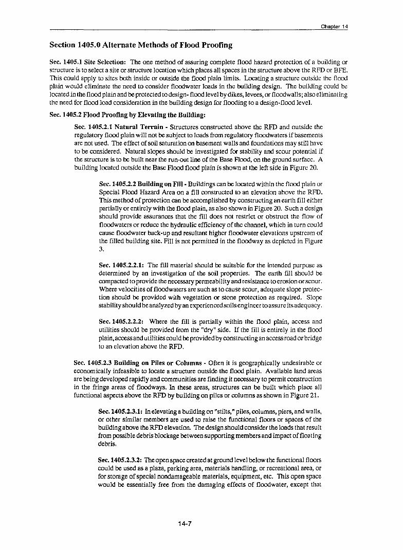
Chapter 14
Section 1405.0 Alternate Methods of Flood Proofing
Sec. 1405.1 Site Selection: The one method of assuring complete flood hazard protection of a building or structure is to select a site or structure location which places all spaces in the structure above the RFD or BFE. This could apply to sites both inside or outside the flood plain limits. Locating a structure outside the flood plain would eliminate the need to consider floodwater loads in the building design. The building could be located in the flood plain and be protected to design- flood level by dikes, levees, or floodwalls; also eliminating the need for flood load consideration in the building design for flooding to a design-flood level.
Sec. 1405.2 Flood Proofing by Elevating the Building:
Sec. 1405.2.1 Natural Terrain - Structures constructed above the RFD and outside the regulatory flood plain will not be subject to loads from regulatory floodwaters if basements are not used. The effect of soil saturation on basement walls and foundations may still have to be considered. Natural slopes should be investigated for stability and scour potential if the structure is to be built near the run-out line of the Base Flood, on the ground surface. A building located outside the Base Flood flood plain is shown at the left side in Figure 20.
Sec. 1405.2.2 Building on Fill- Buildings can be located within the flood plain or Special Flood Hazard Area on a fill constructed to an elevation above the RFD. This method of protection can be accomplished by constructing an earth fill either partially or entirely with the flood plain, as also shown in Figure 20. Such a design should provide assurances that the fill does not restrict or obstruct the flow of floodwaters or reduce the hydraulic efficiency of the channel, which in turn could cause floodwater back-up and resultant higher floodwater elevations upstream of the filled building site. Fill is not permitted in the floodway as depicted in Figure 3.
Sec. 1405.2.2.1: The fill material should be suitable for the intended purpose as determined by an investigation of the soil properties. The earth fill should be compacted to provide the necessary permeability and resistance to erosion or scour. Where velocities of floodwaters are such as to cause scour, adequate slope protection should be provided with vegetation or stone protection as required. Slope stability should be analyzed by an experienced soils engineer to assure its adequacy.
Sec. 1405.2.2.2: Where the fill is partially within the flood plain, access and utilities should be provided from the "dry" side. If the fill is entirely in the flood plain, access and utilities could be provided by constructing an access road or bridge to an elevation above the RFD.
Sec. 1405.2.3 Building on Piles or Columns - Often it is geographically undesirable or economically infeasible to locate a structure outside the flood plain. Available land areas are being developed rapidly and communities are finding it necessary to permit construction in the fringe areas of floodways. In these areas, structures can be built which place all functional aspects above the RFD by building on piles or columns as shown in Figure 21.
Sec. 1405.2.3.1: In elevating a building on "stilts," piles, columns, piers, and walls, or other similar members are used to raise the functional floors or spaces of the building above the RFD elevation. The design should consider the loads that result from possible debris blockage between supporting members and impact of floating debris.
Sec. 1405.2.3.2: The open space created at ground level below the functional floors could be used as a plaza, parking area, materials handling, or recreational area, or for storage of special nondamageable materials, equipment, etc. This open space would be essentially free from the damaging effects of floodwater, except that
14-7
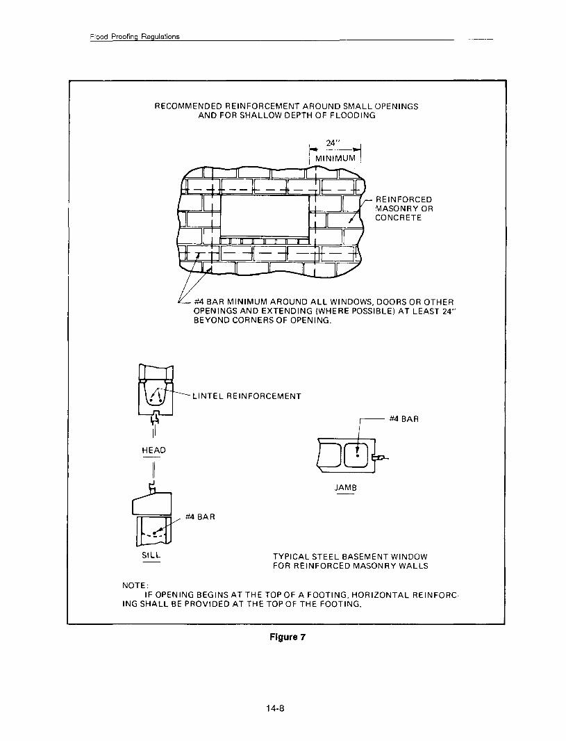
Flood Proofing Regulations
RECOMMENDED REINFORCEMENT AROUND SMALL OPENINGS AND FOR SHALLOW DEPTH OF FLOODING
REINFORCED MASONRY OR CONCRETE
#4 BAR MINIMUM AROUND ALL WINDOWS, DOORS OR OTHER OPENINGS AND EXTENDING (WHERE POSSIBLE) AT LEAST 24" BEYOND CORNERS OF OPENING.
~LINTEL REINFORCEMENT
~ #4 BAR
HEAD
II
~~BAR SILL
NOTE:
JAMB
TYPICAL STEEL BASEMENT WINDOW FOR REINFORCED MASONRY WALLS
IF OPENING BEGINS AT THE TOP OF A FOOTING, HORIZONTAL REINFORC· lNG SHALL BE PROVIDED AT THE TOP OF THE FOOTING.
Figure 7
14-8

SEALING FRAME
Chapter 14
/BOND BEAM OR LINTEL
1,2'' STEEL FLOOD SHIELD~~===V
14"WELD
WINDOW IS REMOVED
,..- 1,2" BOLT WASHER &NUT 2 PER WINDOW
GASKET SEAL J 2-2" X 4"
J ~---MASONRY UNIT REINFORCING SILL FOR MASONRY
SECTION A-A
CLOSURE PANEL FOR BASEMENT WINDOW
FOR SMALL WINDOWS AND SHALLOW DEPTH OF FLOODING
Figure 8
p ~ ~ c
IJ L..---- --------- .J
FLOOD SHIELD BEHIND WINDOW
LOWERED INTO POSITION & ATTACHED TO FRAME WITH QUICK DISCONNECT TYPE FASTENERS
Figure 9
14-9
STO RED FLOOD SHIELD H STIFFENERS WIT
c OUNTERWEIGHT

Flood Proofing Regulations
BOND BEAMS & VERTICAL REINFORCEMENT AT LARGE OPENINGS
_j
_j
-
I r- STEEL OR CONCRETE J L STRUCTURAL MEMBERS ~---
----~·rr:~·~~·==~·~,·ll~-1 \ ~EDGE ·vv- REINFORCEMENT
: Jf jj : I•
Figure 10
,. . 't----' ---·--~· rr = = --,;::- ----., 1
I II I I · I fl I ·
1: 11 r: • l1 11 11 •
II II I r 11 11 11
• I II II rL---~L---.Jr.
:tO .l).:J 0 I•J: C..rLT t ""---1'1-----=-· __ ...;,• ---t't---....
WALL SHOULD BE CONSTRUCTED INTEGRAL WITH STRUCTURAL MEMBER OR SUFFICIENTLY ANCHORED TO IT.
L
REINFORCING FOR BOND BEAMS AND VERTICAL STEEL MAY BE REDUCED IF FORCES ARE TRANSMITTED TO STRUCTURAL MEMBERS BY THE FLOOD SHIELD FRAME AS SHOWN ABOVE.
Figure 11
14-10

I I_
STEEL OR ALUMINUM FLOOD SHIELD ATTACHED TO FRAME WITH
(;1/f I
QUICK DISCONNECT TYPE FASTENERS
_l I
0
Chapter 14
TYPICAL DOOR
It r j_l II . II I ,, .
L- _J ,, II I ,, I II .
7 . ,, I ,, . ~A ,, I
_j_. I I I .~A
SECTION A-A
STIFFENERS
ANCHORS & FLUSH HEAD BOLTS FOR ATTACHING FRAME TO MASONRY UNITS
ALL CELLS AROUND OPENINGS IN HOLLOW MASONRY CONSTRUCTION SHOULD BE FILLED WITH CONCRETE. LARGE OPENINGS SHOULD HAVE BOND BEAMS, VERTICAL REINFORCEMENT, AND METAL FRAMES AROUND OPENING.
MORTAR JOINTS THAT LIE WITHIN FLOOD SHIELD SHOULD BE STRUCK FLUSH WITH THE MASONRY UNITS SO THERE WILL BE A BETTER SEAL.
Figure 12
14-11

Flood Proofing Regulations
DISPLAY WINDOW
rA
FLOOD SHIELD DETAILS DETAIL A
~ li 7' OR
NOTE
L..A ELEVATION
CORNER ANGLE
-.---i"'"'GLASS
~',"ALUM. FLOOD SHIELD
DETAIL A
SECTION A-A
'/2' ALUM. FLOOD SHIELD
~-m~~~-SEENOTE
.. '·. · .. · .. . . ' . . . . . : .. · .. · ..... ,
... · ~ ....
3% X 3 X 3/8
DETAIL B
SUPPORT IS ASSUMED AT THIS LOCATION. WHERE SUPPORT IS NOT AVAILABLE, INCREASE SIZE OR NUMBER OF STIFFENERS AND PROVIDE SUPPORT AT BOTTOM.
MEMBERS ARE SIZED FOR WATER LEVEL AT TOP OF DISPLAY WINDOW.
Figure 13
14-12

CLOSURES FOR HORIZONTAL OPENINGS BELOW RFD
NEOPRENE GASKET OR EQUIVALENT
f ALUMINUM FLOOD SHIELD
' ... : :.
THREAD ANCHORAGE
.
I I I I I I J
l L STIFFENERS
OPENINGi
(a)
(c)
i>. · .. :'·
(b)
T-BOLT OR OTHER QUICK DISCONNECT FASTENER
ROUND OR 0-RING
Cha ter 14
CAST IRON FRAME & COVER FOR SQUARE, RECTANGULAR OR CIRCULAR OPENINGS
GASKET IN MACHINED GROOVE
,.·
(d)
COVERS FASTENED TO FRAME
0 ..
CAST IRON FRAME & COVERS
GRAVITY TYPE COVERS (HELD IN PLACE BY WEIGHT ALONE)
Figure 14
14-13

Flood Proofing Regulations
CLOSURE PANEL ASSEMBLY FASTENING METHODS
WALL
ANGLE FRAME
CLOSURE PANEL ASSEMBLY
(a)
(c)
WALL
SEAL
(e)
GASKET SEAL
SLOTIED PIN
CHANNEL FRAME
LATCHING DOG
CHANNEL FRAME
PAWL-SET WITH HAMMER BLOW
WALL
CLOSURE PANEL ASSEMBLY
(b)
SEAL
SLOTIED ----. THREADED STUD
STRIP
WALL
CLOSURE PANEL -----....: ASSEMBLY
(d)
SLOTIED STEEL SELF-TAPPING SCREWS
NEOPRENE 0-RING OR SOLID GASKET SEAL
CLOSURE PANEL ASSEMBLY
(f)
Figure 15
14-14

Cha ter 14
FLOOD-PROOFING CLOSURE FOR LARGE HORIZONTAL OPENING BELOW RFD
SWIVEL
REMOVABLE BA:R
~~~~~~~~~~~G~ASKET . -~
ANGLE FRAME
GUIDE HOLE
ANGLE TRACK- ATTACHED TO< FRAME AT OPENING AND PAVEMENT
ANGLE FRAME
(a) (b)
AL TEA NATE POSITIONING METHODS
PROCEDURE BEFORE FLOOD- Closure assembly remains in stored position and rests on blocks to keep assembly weight off 0-Aing or flat sealing gasket·wheels in an up position and operating bars removed. Wheel assembly is coated with heavy grease and covered with plastic or canvas sheet. DURING FLOOD- When flood warning is received, operating bar(s) inserted in retractable wheel assembly and wheels lowered to engagp rails, raising closure assembly off storage blocks and high enough to clear positioning studs; closure assembly rolled into position where guide holes are di· reedy over positioning studs; closure assembly lowered to engage studs until all wheels are free·at guide rails and contact established between gasket and frame; operating bars then removed from wheel assembly_ Positive seal is maintained during flood by weight of closure assembly and flood water weight; positioning studs prevent displacement or movement of closure assembly. AFTER FLOOD- Closure assembly washed down to clear mud and debris, raised into rolling position, rolled to storage location and positioned, inspected for possible damage, then "moth-balled" for future use.
NOTE: This illustrates only one of many schemes that may be considered for horizontal opening flood-proofing. Closure assemblies should be of durable materials for repeat type use, should re· quire minimum maintenance, and require minimal installation effort. Variations rnay include hinged and/or counter-balanced assemblies; lever, ratchet or hydraulic systems for movement and positioning of assembly; positioning lugs, wedges, recesses. etc. where exposed studs cannot be tal· erated; and use of positive fastening methods and devices for special locations or situations. The methods, procedures, and equipment that may be utilized are limited only by the deSigner's imagination and the owner's pocketbook.
Figure 16
14-15
(c)
Flood Proofing Regulations
... -
FLOOD SHIELD INSTALLATIONS
~ .-.rf .-.
ROLLER
- -
FLOOD ~ SHIELD
•
SLIDING FLOOD SHIELD FOR DOOR
Figure 17
I
' \ \ '\
" " ---
~
-sEALING F
HINGED FLOOD SHIELD FOR LOADING DOCK
Figure 18
RAME
SEALING FRAME
.._-++-FLOOD SHIELD
WATER PRESSURE EQUALIZATION HOLE
STORED FLOOD SHIELD BEHIND WINDOW
Figure 19
SECURED TO SEALING FRAME BY LATCHING DOGS, WEDGE ASSEMBLIES, OR OTHER QUICK DISCONNECT FASTENERS.
14-16

DOD DOD DOD
Cha ter 14
RFD LIMIT OF OVERLAND FLOODING
DODO DODO REGULATORY FLOOD DATUM
FILL
STRUCTURES ON NATURAL TERRAIN OR FILL
Figure 20
BUILDING ON PILES OR COLUMNS
Figure 21
14-17
OPERATING EQUIPMENT
RFD

Flood Proofing Regulations
lobbies and entrance would have to be protected by some approved flood proofing method.
Sec. 1405.2.3.3: The equipment necessary to maintain building functions should be located safely above the RFD. If access to the building were provided from a location above the RFD, the normal building activities would not be disrupted and the building could continue to function during the flood emergency.
Sec. 1405.3 Protection by Dikes, Levees, and Floodwalls: As an alternative to providing flood protection through building or structure modifications, the necessary protection may be achieved by detached dikes, levees, or floodwalls. The primary purpose of these constructions is to prevent the flood from reaching the structure and associated functional land areas. The choice of using a dike or floodwall is made on the basis of economic considerations when compared to structural flood proofing modifications, the ability of a structure to be structurally modified, and the degree of protection to be provided. The type of protection barrier depends on location, availability of material, foundation conditions, and right-of-way restrictions. Floodwalls would be used in tight, restricted areas where foundation conditions are favorable. Dikes or levees would be used where adequate space and material are available. The dike or floodwall may not have to completely surround a structure. Protection may be required only on the low sides as illustrated in Figures 22 and 23. The ends of the works would be tied into the existing high ground or to the structure depending on local conditions. Reference section 612.3 of these regulations for NFlP requirements
Sec. 1405.3.1 Dikes -If used, dikes should be constructed to a section capable of supporting the imposed loads and providing the required impermeability. Suitable material preferably should be available at the site and should be tested and approved for use prior to constructing the dike. An investigation should also be made of the foundation material to determine the presence of, location, and extent of unsuitable materials, and necessity for drainage of cutoff provisions.
Sec.1405.3.1.1: At locations where the foundation material has a high degree of permeability, an impervious cutoff may be necessary to reduce seepage through the in situ foundation materials. The cutoff may be a sheet pile wall, compacted barrier of impervious soil, fabric reinforced membrane, concrete wall, or a grouted cutoff. As no cutoff is totally impermeable, provisions should be made to collect the excess seepage and any seepage from Jess permeable soils without cutoffs. The excess seepage can be collected with drainage blankets, pervious trenches, or perforated pipe drains placed at the toe of the embankment and on the dry landward side. Typical dike sections, cutoffs, and drainage provisions are shown in Figures 24, 25, and 26.
Sec. 1405.3.1.2: If any drain pipes or related structures are within a dike, they should be designed to resist all applicable loads and be provided with gates to prevent backflow to the dry side. Backflow through conduits can be prevented by installing flap gates, manually operated valves, or slide gates that would be closed when floodwaters would reach critical elevations.
Sec. 1405.3.2 Flood walls- A floodwall is subject to hydraulic loading on one side with little or no earth loading as a resisting force on the opposite side. Floodwalls can be constructed as cantilever !-type sheetpiling walls, cellular walls, buttress walls, or gravity walls.
Sec. 1405.3.2.1: The walls should be founded on and keyed into rock where suitable rock is encountered reasonably close to the founding elevations. Where the soil provides inadequate bearing capacity and removal of unsuitable material and replacement is costly, an adequately designed system of piling should be considered. Cutoff and drains should be used to intercept seepage as required in 612.3.2. Drain pipes should not be placed directly under the wall base and any drainage provided should not be considered as a factor for reduction of uplift
14-18

--
Cha ter 14
""', REGULATORY FLOOD DATUM
---------FLOODWALL ----,
l----SHEETPILE CUTOFF
FLOOD PROTECTION WITH FLOODWALLS
FLOOD PROTECTION BY DIKES Figure 23
14-19
DRAINAGE STRUCTURE

Flood Proofing Regulations
DIKE OR LEVEE PROTECTION
DOD DOD DOD
REGULATORY FLOOD DATUM
COMPACTED FILL
LEVEE WITH SHEETPILE CUTOFF
Figure 24
THESE OR OTHER MEANS -SHOULD BE PROVIDED TO NEGATE EFFECTS OF SEEPAGE ON BUILDING
IMPERVIOUS FILL
-----------BLANKET DRAIN
DIKE WITH BLANKET DRAIN
ROCK OR IMPERVIOUS STRATUM
Figure 25
DIKE WITH IMPERVIOUS CORE
Figure 26
14-20
ROCK OR IMPERVIOUS STRATUM

Cha ter 14
pressures. The problem of scour should be further investigated and corrective measures provided where necessary.
Sec. 1405.3.2.2: Drainage features through floodwalls should be equipped with the necessary devices to prevent backflow. Typical sections of various flood wall types are shown in Figure 27.
Sec. 1405.4 Controlled or Intentional Flooding: In many situations, the basement walls and floor slab(s) of existing buildings and structures lack the structural strength required to withstand flood loadings. The expense of reinforcing an existing structure or replacement with a new structure at the same location to withstand such flood loadings is, in most cases, not justified. As an alternate means of flood proofing these structures, provisions may be made for flooding of the structure interior to balance the external flood pressures on the building com{Xments. This intentional flooding would have to be accomplished in such a manner as to keep the unbalanced hydrostatic pressures safely within the load carrying capacity ofthe slab and walls. Provisions must be made for interconnections through and around all floors and partitions in order to prevent unbalanced filling of chambers or spaces within the structures. This is also known as wet flood proofing (See Section 401.7 Wet Flood Proffing and the National Flood Insurance Program).
Sec. 1405.4.1 Flooding: Flooding should be with potable water from a piping or storage system of adequate capacity to fill the basement at a rate consistent with the anticipated floodwater rise. The provisions should be such as to keep the internal water surface as nearly even with the outside as possible. All spaces should be provided with air vents to prevent the trapping of air by the rising water surface.
Sec. 1405.4.2 Draining: Outlets to drain the water as flood waters recede should be located to completely drain the structure and all spaces at a uniform rate corresponding to that of the receding waters. The water level in all interior spaces should be kept even and all spaces should be completely drained. Upper spaces and levels should be drained before the lower spaces. All watertight walls should be designed for an internal hydrostatic pressure resulting when waters trapped in the building are higher than those of the receding floodwaters outside, which is possible with the ma1function of required drains.
Sec. 1405.4.3 Use: Where provisions are made for internal flooding, all floors and spaces below the RFD should be restricted as to types of use permitted. Examples of controlled flooding of structures with restricted use are shown on Figures 28 and 29.
Sec. 1405.4.4 Backflow: Where intentional flooding with potable water is proposed (or where floodwater backflow through the sewer system may occur), backflow preventers should be installed in the sewer lines. Various types of backflow preventers are illustrated in Figure 30.
Section 1406.0 Total Approach
Sec. 1406.1 General: The design and implementation of flood proofing systems and procedures requires a total approach. No element or item, regardless of how minute it might appear, should be overlooked or left to chance. The most elaborate, extensive, and expensive flood proofing system may be rendered useless by a minor omission or by the failure of a weak link in the system.
Sec. 1406.2 Standard Operating Procedure: The same "in toto" approach is necessary in establishing detailed procedures for making a contingently flood proofed system ready for an expected flood. Standard operating procedure for mobilizing and implementing the flood proofing measures, referred to in these Regulations as "The Owner's Contingency Plan," should be developed by the original designer of the system. It requires a degree of completeness such that all details, sequences, and implementing personnel assignments are fully spelled out. The building owners and all other personnel assigned to implement the Plan should be thoroughly acquainted with all aspects of the operation and procedure. All personnel should periodically inspect the system and participate in scheduled "dry runs" or exercises of the flood proofing plan. The standard operating procedure should be in the format of a manual containing all descriptive information and operational sequences, along with necessary illustrations, drawings, and maintenance requirements for all measures.
14-21

Flood Proofing Regulations
Type 1 Type 2
CANTILEVER 1-TYPE SHEET PI LING
CELLULAR
BUTTRESS AND COUNTERFORT
GRAVITY
VARIOUS FLOOD WALL TYPES
Figure 27
14-22
Type 3
FLAT DAM

OPERATING EQUIPMENT
STRUCTURES WITH RESTRICTED USE
PARKING LEVELS
RFD
STRUCTURE ON NATURAL TERRAIN OR FILL
Figure 28
STRUCTURE ON NATURAL TERRAIN OR FILL
Figure 29
14-23
Cha ler 14

Flood Proofing Regulations
PREVENTION OF BACKFLOW THRU SEWER SYSTEM
(a) (b)
FLOOR DRAIN WITH INTEGRAL BACKWATER VALVE
BACKWATER VALVE- FLAPPER TYPE- AUTOMATIC
BACKWATER VALVE- GATE TYPE COMBINATION- MANUAL & AUTOMATIC
r--L-_- :IFP~ ~ STEEL PLATE
WITH GASKET BOLT
REMOVE GRATE AND INSTALL STANDPIPE. USE ONLY WHERE FLOOR SLAB WILL TAKE UP-LIFT PRESSURES
EXISTING BASEMENT DRAIN FLOOD-PROOFING
Figure 30
14-24

Cha ter 14
Personnel designated to perform each task should be noted and, if possible, alternates should be assigned to assist during times of emergencies or to take over and act if the regularly assigned personnel are absent or unavailable for flood emergency duties. In addition, summarized procedures should be posted at prominent building locations to facilitate and expedite the operation. Color-coding of flood proofing implements, such as closure panels, backflow valves, and similar features would be helpful in assuring the most efficient implementation of the Plan.
Sec. 1406.2.1: As preparation of a building for a flood event often involves auxiliary personnel, equipment, and materials, planning for simple logistics should be developed and be closely keyed to available advance time. In this respect, information from flood forecasting and warning sources must be obtained at the earliest possible time. Since floods can occur at any time of the day or night, on weekends or holidays, a plan for emergency readiness must be established. It should include establishment of definite lines of communications and control, and identification of key personnel who can be counted on to respond whenever needed.
Sec. 1406.2.2: All systems and implements offload proofing must be kept in a perfect state of readiness and be easily accessible at all times. The emphasis on periodic inspection, testing, and continued maintenance cannot be adequately stressed.
14-25

References
1. Design of Welded Structures, Orner W. Blodgett, The James F. Lincoln Arc Welding Foundation, Cleveland, Ohio
2. Introduction to Flood Proofing, John R. Sheaffer, The Center of Urban Studies, 1967, University of Chicago, lllinois
3. Wall Design, Flood Walls, Part CXXV Chapter 1, January 1948, Dept. of the Army, Corps of Engineers, Office of the Chief of Engineers, Washington, D.C.
4. Design Manual- Soil Mechanics, Foundations and Earth Structures NA VFAC DM-7, March 1971, Dept. of the Navy, Naval Facilities Engineering Command, Washington, D.C. 20390
5. Flood-Proofing: An Element in a Flood Damaged Reduction Program, John R. Sheaffer, Chicago: University of Chicago, Dept. of Geography, Research Paper No. 65, 1960
6. Floods, Flash Floods and Warnings, U.S. Department of Commerce, NOAA-National Weather Service, PA81010, 1981.
7. Technical Standards Bulletin- Wet Floodproofing (Draft), Federal Emergency Management Agency, Bulletin No. 85-1
8. National Flood Insurance Program (Regulations for Flood Plain Management and Flood Hazard Identification), Revised as of October 1, 1988.
*U.S. GOVERNMENT PRINTING OFFICE: 1998 - 721 - 098 I 83091
References-1