distribution restriction statement - pirate4x4 and design...guidance for tainter gate design called...
TRANSCRIPT

CECW-EE
Engineer Manual1110-2-3200
Department of the ArmyU.S. Army Corps of Engineers
Washington, DC 20314-1000
EM 1110-2-3200
30 September 1998
Engineering and Design
WIRE ROPE SELECTION CRITERIA FOR GATE-OPERATING DEVICES
Distribution Restriction StatementApproved for public release; distribution is
unlimited.

DEPARTMENT OF THE ARMY EM 1110-2-3200U.S. Army Corps of Engineers
CECW-EE Washington, DC 20314-1000
ManualNo. 1110-2-3200 30 September 1998
Engineering and DesignWIRE ROPE SELECTION CRITERIA FOR GATE-OPERATING DEVICES
1. Purpose . This manual provides information and criteria important to the selection, installation, andmaintenance of wire rope and fittings. It applies primarily to gate-operating devices within the Corps ofEngineers’ responsibility.
2. Applicability . This manual applies to all USACE Commands having civil works responsibilities.
3. General. A unique problem facing the Corps is the wide variety of wire rope service conditions,which are determined by rope and hoisting equipment design, frequency of use, and the operatingenvironments that exist at Corps installations. This manual covers many of these conditions and presentsthe latest state-of-the-art technology from commercial and industrial sources and information fromexisting Corps projects. Its purpose is to optimize the service life of wire rope and to reduce thelikelihood of future failures.
4. Distribution Statement . This manual is approved for public release; distribution is unlimited.
FOR THE COMMANDER:
ALBERT J. GENETTI, JR.Major General, USAChief of Staff

i
DEPARTMENT OF THE ARMY EM 1110-2-3200U.S. Arm y Corps of En gineers
CECW-EE Washin gton, DC 20314-1000
ManualNo. 1110-2-3200 30 September 1998
Engineerin g and Desi gnWIRE ROPE SELECTION CRITERIA FOR GATE-OPERATING DEVICES
Table of Contents
Subject Para graph Page Subject Para graph Page
Chapter 1 Cha pter 4Introduction Optimum Desi gnPurpose and Scope . . . . . . . . . . . . 1-1 1-1Applicability . . . . . . . . . . . . . . . . . 1-2 1-1References . . . . . . . . . . . . . . . . . . 1-3 1-1Distribution Statement . . . . . . . . . 1-4 1-1Wire Rope Failure, Service Conditions, and This Manual . . . . . . . . . . . . . . . . . . . . 1-5 1-1
Chapter 2Rope Constructionand MaterialsClassification . . . . . . . . . . . . . . . . 2-1 2-1Lay . . . . . . . . . . . . . . . . . . . . . . . . 2-2 2-3Special Shaping of Ropes/Strands. . . . . . . . . . . . . . 2-3 2-5Flat Rope . . . . . . . . . . . . . . . . . . . 2-4 2-6Wire Materials . . . . . . . . . . . . . . . 2-5 2-6Core Materials . . . . . . . . . . . . . . . 2-6 2-6Coating/Filling/Plating. . . . . . . . . 2-7 2-7Manufacturing . . . . . . . . . . . . . . . 2-8 2-7
Chapter 3Sockets and EndTerminationsSockets . . . . . . . . . . . . . . . . . . . . . 3-1 3-1Materials/Coatings . . . . . . . . . . . . 3-2 3-2Drum and Miscellaneous Terminations . . . . . . . . . . . . . . . 3-3 3-2Seizing/Cutting/Splicing . . . . . . . . 3-4 3-3Two-Piece Ropes. . . . . . . . . . . . . 3-5 3-3
Service Conditions and Failure Modes . . . . . . . . . . . . . . . 4-1 4-1Calculating Rope Load . . . . . . . . . . 4-2 4-3Sheaves . . . . . . . . . . . . . . . . . . . . . . 4-3 4-3Nominal Strength . . . . . . . . . . . . . . 4-4 4-4Factor of Safety . . . . . . . . . . . . . . . 4-5 4-4Service Life . . . . . . . . . . . . . . . . . . 4-6 4-5Rope Length/Stretch. . . . . . . . . . . . 4-7 4-5Bending Radii . . . . . . . . . . . . . . . . . 4-8 4-6Bearing Pressure . . . . . . . . . . . . . . . 4-9 4-6Fleet Angle . . . . . . . . . . . . . . . . . . . 4-10 4-7
Chapter 5Specif ying Wire Ro pe Standard Nomenclature . . . . . . . . . . 5-1 5-1Additional Requirements . . . . . . . . 5-2 5-1Availability/Cost . . . . . . . . . . . . . . . 5-3 5-2Buy American . . . . . . . . . . . . . . . . . 5-4 5-3
Chapter 6Field Acce ptanceand InstallationField Acceptance. . . . . . . . . . . . . . 6-1 6-1Storage, Handling, and Unreeling . . 6-2 6-1Installation . . . . . . . . . . . . . . . . . . . 6-3 6-1
Chapter 7Inspection, Maintenance,Retirement, Etc.Inspection . . . . . . . . . . . . . . . . . . . . 7-1 7-1Retirement . . . . . . . . . . . . . . . . . . . 7-2 7-3

EM 1110-2-320030 Sep 98
ii
Subject Paragraph Page Subject Paragraph Page
Lubrication . . . . . . . . . . . . . . . . . . . 7-3 7-4Ice and Debris Removal . . . . . . . . . 7-4 7-4Painting . . . . . . . . . . . . . . . . . . . . . 7-5 7-4Cathodic Protection. . . . . . . . . . . . 7-6 7-5
Appendix AReferences
Appendix BGlossary
Appendix CNominal Strengthsand Testing
Appendix DTerminations andEfficiencies
Appendix ETest Links and TensionLimiting Devices
Appendix FKevlar Wire Rope
Appendix GSample InspectionReport Checklist
Appendix HLubrication and LubricantData
Appendix IMethods for Deicing
Appendix JSample Problem
Index

EM 1110-2-320030 Sep 98
1-1
Chapter 1Introduction
1-1. Purpose and Scope
This manual provides information and criteriapertinent to the selection, installation, andmaintenance of wire rope and fittings. It appliesprimarily to gate-operating devices within the Corps ofEngineers' responsibility.
1-2. Applicability
This manual applies to all USACE Commands havingcivil works responsibilities.
1-3. References
The required and related publications are listed inAppendix A.
1-4. Distribution Statement
Approved for public release; distribution is unlimited.
1-5. Wire Rope Failure, Service Conditions,and This Manual
a. The Corps has recently experienced wire ropefailures at a number of projects. These failures
prompted the development of this manual. Wire ropefailures typically render gates inoperable causingdelays to navigation, flooding potential, equipmentdamage, and possibly even personnel injury.
b. A unique problem facing the Corps is the widevariety of wire rope service conditions, which aredetermined by rope and hoisting equipment design,frequency of use, and the operating environments thatexist at Corps installations. This manual covers manyof these conditions and presents the latest state-of-the-art technology from commercial and industrial sourcesand information from existing Corps projects. Itspurpose is to optimize the service life of wire rope,and to reduce the likelihood of future failures.
c. Chapters 2 and 3 present information onconstruction and materials for rope and fittings.Chapter 4 presents the calculations/data to select ropewithin engineering standards. Chapter 5 explains howto specify or order rope. Chapter 6 presentsinformation on accepting and installing rope, andChapter 7 covers inspection and maintenance.

EM 1110-2-320030 Sep 98
2-1
Figure 2-1. The three components of a typical wirerope
Chapter 2Rope Construction and Materials
Wire rope consists of multi-wire strands laid helicallyaround a core (Figure 2-1). The way the wires are laidto form the strands, the way the strands are laid aboutthe core, the core construction, and the materials andcoatings used for the components contribute to theoverall properties of the rope. The following sectionsdiscuss rope properties in regard to construction andmaterials. They do not cover all the available types ofwire rope, but attempt to cover the types applicable togate-operating devices.
2-1. Classification
a. Designation method. Wire rope classificationis designated by the construction of the rope as seen incross section. The number of strands and the numberof wires in each strand are respectively given in itslabel, for example: 6x19, 6x37, 7x19, 8x61, etc.(Figures 2-2 and 2-3).
b. Strand configuration. Note that the nominalclassifications may not reflect the actual construction.For example, the 6x19 classification includes 6x21Filler Wire, 6x19 Seale, and 6x26 Warrington Sealeconstructions. The terms Filler Wire, Seale, Warring-ton, and Warrington Seale refer to the layers and theconfigurations of the strands (Figures 2-4 and 2-5).Note that for the Seale configuration, the wires in anylayer of the strand are of equal diameter. For theWarrington configuration, the wires of the outer layerof the strand are of two different diameters. TheWarrington Seale configuration is a blend of the Sealeand Warrington configurations. The outer layer hasequal diameter wires and the next layer inward haswires of two different diameters. For the Filler Wireconfiguration, all the main wires of each strand are ofequal diameter like the 7-Wire configuration. How-ever, extra wires of a small diameter have been addedbetween the main wires. Compared to the 7-Wireconfiguration, the more complicated configurationsresult in strands which are more stable, flexible, andless likely to collapse under load.
c. Rope properties. Important characteristics ofwire rope relate to the number and size of the outerwires, and to a lesser extent, the inner wires. A smallnumber of large outer wires results in better resistanceto wear and corrosion. A large number of small wiresresults in better flexibility and resistance to fatigue.Section 4-6, “Service Life” gives data on ropeclassification versus service life. Figure 2-6 is referredto as the “X-chart” by the wire rope industry. It showsan inverse relationship between abrasion resistance

EM 1110-2-320030 Sep 98
2-2
Figure 2-2. Six-strand classes
Figure 2-3. Seven-strand classes
Figure 2-4. Basic strand patterns

EM 1110-2-320030 Sep 98
2-3
Figure 2-5. Combination strand patterns
Figure 2-6. The “X-chart” as referred to by the wire ropeindustry
which may be more appropriate for a small rope, sayand resistance to bending fatigue for some widelyused wire rope constructions. For many installations,both wear and fatigue may be a concern, which wouldrequire a compromise. Engineering judgment in con-sidering the application is needed to determine thetrade-off between fatigue resistance and wear resis-tance. Strength also varies somewhat with classifica-tion and is shown in Appendix C. Note that just as theclassification (number of strands x number of wiresper strand) is a relative indication of wire size, so isstrand configuration. For example, a strand of theFiller Wire configuration will likely have some wiresof a much smaller diameter than any of the wires in astrand of the Seale configuration.
d. Classifications for gate-operating devices. It isimpossible to present here an all-inclusive list of wirerope classifications suitable for gate-lifting devices.However, 6x37 has long been considered appropriateby most manufacturers for lifting devices. Pastguidance for Tainter gate design called for 6x25type B flattened strand rope. Gate-lifting devices havefrequently used 6x37 Fiber Core (FC) and 6x30
Independent Wire Rope Core (IWRC). This does notsuggest that any of these classes will be the bestengineering choice for any particular device, but theywould normally be among the first ones considered inthe engineering analysis. Note that in considering theinitial selection, it may be wise to keep wires in amanageable size. That can be done by consideringboth construction and strand configuration. Inregards to construction, if a device uses a very smalldiameter rope, say 16 mm (5/8 in.), initially considera construction such as 6x7. If a device uses amedium diameter rope, say 32 mm (1-1/4 in.),initially consider a construction such as 6x19. If adevice uses a large diameter rope, say 64 mm (2-1/2in.), initially consider a construction such as 6x37. Inthis way, a small rope would have relatively largewires and large rope would have relatively smallwires. The wires tend to be relatively constant in sizethrough a large range of rope size. Thecharacteristics of the wires in regards to abrasion andcorrosion would be similar. In regards to strandconfiguration, note that strands with a WarringtonSeale configuration have relatively small inner wires.This configuration may be appropriate for a largerope, say 52 mm (2 in.). However, strands with aSeale configuration, have relatively large inner wires
26 mm (1 in.). Again, but to a lesser extent, the wirestend to be relatively constant in size through a rangeof rope size. Finally, note that the Filler Wire strandconfiguration is not applicable for rope for gate-lifting devices. This is because its filler wires are sorelatively small, that even in very large ropes, theirabsolute size is too small. The small wires areunsatisfactory because of corrosion concerns.
2-2. Lay
a. Designation method. The lay of a wire rope isdesignated by direction and type (Figure 2-7). Direc-tion is right or left according to how the strands havebeen laid around the core. The lay type is eitherregular or lang, depending on whether the wires inthe strands are laid in the opposite direction of thestrands or the same direction as the strands.
b. Right versus left lay. Right lay rope isstandard. If lay direction is not designated, right layi s

EM 1110-2-320030 Sep 98
2-4
Figure 2-7. Direction and type of lay: (a) right regularlay, (b) left regular lay, (c) right lang lay, and (d) left langlay
Figure 2-8. The difference in wear characteristics oflang lay and regular lay ropes
Figure 2-9. Wire direction of lang versus regular layrope
Figure 2-10. Bearing/wear areas of lang lay versusregular lay rope
drum. If the correct lay is not used in this case, therope will not wind smoothly against its previous wrap.
c. Regular lay versus lang lay. The wires inregular lay wire rope appear to line up with the axis ofthe rope. In contrast, the wires in lang lay wire ropeappear to form an angle with the axis of the rope.Regular lay wire rope is used for the widest range ofapplications. It has a somewhat better resistance tocrushing than lang lay wire rope and does not rotate asseverely under load when used in an application whereeither end of the rope is not fixed. Lang lay wire ropehas two important advantages. It has better resistanceto both fatigue and abrasive wear. Lang lay rope has alonger exposed length of exterior wires. Bending oflang lay rope results in less axial bending of the outerwire, but greater torsional flexure. Overall, lang laywire rope displays a 15 to 20 percent superiorityin service life over regular lay when bending isthe principal factor affecting service life. Also,because of the longer exposed length of the exteriorwires, the ropes are exposed to less pressure whichdecreases the rate of abrasive wear on wires, drums,and sheaves (Figures 2-8 through 2-10). There is nodifference in breaking strength between lang andregular lay rope. the regular lay type. However, many installations
d. Rope lay in Corps applications. Most of the replacement should be considered for any regular laywire rope used for Corps gate-operating devices is of wire rope which has failed due to wear or fatigue.
would be better served with lang lay ropes. A lang lay

EM 1110-2-320030 Sep 98
2-5
Figure 2-11. Compacted strand wire rope crosssections
Figure 2-12. Compacted wire rope cross sections
Figure 2-13. Flattened strand wire rope cross sections
Lang lay wire rope is potentially more prone tokinking and underlaying or opening up. Therefore, arope tensioning device such as a turnbuckle may beappropriate on gates where lang lay ropes are used.
2-3. Special Shaping of Ropes/Strands
a. General. Manufacturers vary rope from thestandard round wire and round strand configurationsto enhance some of its properties. The variationscovered in this section are (1) compacted strand wirerope, (2) swaged (compacted) wire rope, and (3) flat-tened strand (triangular) wire rope (Figures 2-11through 2-13). Manufacturers should be consultedwhen specifying specially shaped rope to verify thatall the characteristics of the special shape are consis-tent with the needs of the application.
b. Compacted strand wire rope. Compactedstrand wire rope is manufactured from strands whichhave been reduced in diameter by one of severalswaging processes. The outer surfaces of the outerstrand wires are flattened and the internal wires are no
longer round. Compared to a standard wire rope ofthe same diameter, a rope of the compacted strandconfiguration has a greater cross-sectional area ofmetal. This results in higher strength and lessresistance to fatigue. It has a smoother surface whichmakes it more abrasion resistant, but it is lesscorrosion resistant for two reasons. First, its smoothersurface is less able to hold lubrication. Second, theswaging process used to form the strands is notcompatible with stainless steel, which is the materialof choice for corrosion resistance.
c. Swaged (compacted) wire rope. A standardIWRC wire rope is used to form compacted wire rope.Its entire cross section is reduced in diameter, usuallyby rotary swaging. Compared to a standard wire ropeof the same diameter, it has a greater cross-sectionalarea of metal and flatter wires on the outer surface.The smooth outer surface provides good wearresistance. It is also stronger and more resistant tocrushing, but fatigue life is reduced by the compactingprocess. Like compacted strand rope, it is lesscorrosion resistant for the same reasons.
d. Flattened (triangular) strand wire rope.Flattened strand wire rope features strands which aretriangular in shape. The center of the strands consistof either a triangular-shaped wire or of wires laid in atriangular configuration. Compared to a standard wirerope of the same diameter, it has a greater cross-sectional area of metal and an increased bearingsurface. Strength, abrasion resistance, and resistanceto crushing are enhanced with the flattened strandconfiguration. Fatigue resistance is unaffected.Flattened strand wire rope can be obtained with eitherFC or IWRC and is usually furnished in lang

EM 1110-2-320030 Sep 98
2-6
lay. This variation is compatible with stainless steel, other equipment rapidly corrode. See Sections 3-2,which makes it the most useful of the special shapes “Materials/Coatings and 7-6, “Cathodic Protection.”for gate-operating devices.
2-4. Flat Rope
A number of older Corps installations use flat wirerope for gate-operating devices. Flat rope is alwayslayered over its drum and has generally providedsatisfactory service. However, it is expensive tomanufacture and requires a long lead time. Expertisein fabricating flat rope is no longer available. Whenflat rope is retired, it is normally replaced with roundrope, along with modifications to the hoistingequipment. See Section 5-3, “Availability/Cost.”
2-5. Wire Materials
a. Steels.
(1) Carbon steels. The grades of carbon steel wirerope are Traction Steel (TS), Plow Steel (PS),Improved Plow Steel (IPS), Extra Improved PlowSteel (EIPS), and Extra Extra Improved Plow Steel(EEIPS). Of these, only EIPS and EEIPS are normallyspecified for gate-operating devices. TS is normallyused for elevators. PS and IPS ropes are nearlyobsolete and are seldom stocked or fabricated bymanufacturers. EIPS is much stronger than TS andhas similar toughness. EIPS carbon steel rope isstronger than the stainless steels and has betterresistance to abrasive wear.
(2) Stainless steels. Of the stainless steelsavailable, only types 302 and 304 have been usedregularly on gate-operating devices. Any other stain-2-6. Core Materialsless steels would be experimental. A 10 to 15 percentloss of strength is typical compared to the IPS andbetter carbon steels. Stainless steels are not asresistant to abrasive wear and are susceptible togalling when layered over sheaves. Since they arenot magnetic, inspection by the electromagnetic(non-destructive) method is not possible. Thestainless steels are many times more corrosionresistant than the carbon. However, it is important tonote that the stainless steels have a different galvanicpotential than the carbon steels. When using stainlesssteel rope, it is possible to set up a galvanic corrosioncell in which carbon steel sockets, rope fittings, or
b. Brass/bronze/monel. The non-ferrous metalsare more corrosion resistant in salt water than thesteels but are susceptible to rapid abrasion. Theywould rarely be applicable for Corps of Engineersgate-operating devices.
c. Kevlar. At Corps installations where the waterhas proven to be very corrosive to the submergedportions of wire ropes, Kevlar replacement ropes havegiven satisfactory results. Kevlar's properties are verydifferent from steel for abrasion resistance, crushingresistance, and elasticity. Kevlar wires are verysusceptible to abrasion damage and they must beprotected with a jacket, usually of a polyethylenematerial. The jacket reduces the usable cross sectionof the rope, but a jacketed Kevlar rope has about thesame breaking strength as a stainless steel rope of thesame diameter. This strength makes it possible toattain normal factors of safety with Kevlarreplacement ropes. Because of the jacket, inspectionis difficult compared to bare metal wire rope.However, a change in appearance does occur prior tofailure. Kevlar rope, when used with multiple layeredtype drums soon crushes from a round shape to analmost square shape, but does not lose its integrity.Kevlar rope stretches about two times as much as steelunder a full load. Therefore, it stores more energy anda rope breakage will release more energy. A higherdegree of personnel protection should be consideredwhere Kevlar rope is used. (See Appendix F forinformation on Kevlar rope.)
a. General. As previously stated, wire ropeconsists of multi-wire strands laid helically around acentral core. The core contributes very significantly tothe overall properties of the rope. There are two typesof cores, Fiber Core (FC) and Independent Wire RopeCore (IWRC).
b. Fiber core (FC). The core in FC wire ropeprovides no real strength for either crushing ortension. The fiber tends to dampen out vibration, anadvantage for some applications, such as elevators.FC is more flexible than IWRC, but flattens under

EM 1110-2-320030 Sep 98
2-7
load, inhibiting the free internal adjustment of the possible to zinc-coat a rope after weaving. A ropewires, which increases stresses. In the past it was galvanized in this manner would have no reduction inthought that its core had a significant lubricant holding strength compared to one of bare steel. Either of theability. That is not presently considered a real last two galvanizing methods would be preferable toadvantage. FC wire rope is not well suited for gate- the first for gate-operating devices. Galvanized carbonlifting devices. steel rope is generally very corrosion resistant
c. Independent wire rope core (IWRC). The zinc coating disappears. Rate of zinc loss can be veryadvantages of IWRC are its strength in tension and its high in industrial areas because of airborne pollution.resistance to crushing. Its only disadvantage is Galvanized rope is much lower in cost than stainlessdecreased flexibility. Since bending around drums steel (See Section 5-3, “Availability/Cost”). It is alsoand sheaves at high loads is required for most gate- stronger than stainless steel if manufactured fromoperating devices, IWRC wire rope is generally drawn galvanized rope wire. In addition, it is lesspreferred for these applications. susceptible to damage from nicks and does not have
2-7. Coating/Filling/Plating
a. General. In general, galvanized carbon steelrope is the only plated, filled, or coated metal rope This section presents information on various ropesuitable for gate-operating devices at Corps manufacturing processes.installations. The plastic-filled and plastic-coatedropes have certain disadvantages in regards to a. Stress relief. Newly woven wire rope iscorrosion and inspection. normally run through molten lead to relieve stresses in
b. Plastic-filled. Plastic-filling helps prevent preforming, and swaging processes. If not stressabrasion as the individual wires move relative to each relieved, the fatigue life of the rope is shortened.other. However, concentrated corrosion cells willform at the exposed wires in a wet environment b. Pre-stretching. Wire rope normally stretchesmaking plastic-filled rope unsatisfactory for gate- more rapidly when new than it does as it ages. Pre-operating devices. stretching is an operation which takes most of the
c. Plastic-coated. Plastic-coated rope is difficult lished economically if performed in conjunction withto inspect. Also, the coating soon wears off making it socketing. Pre-stretching is recommended for installa-similar to a plastic-filled rope. tions with multi-rope drums, where the ropes need
d. Galvanized steel. Galvanized carbon steel rope performed, the ropes may tend to stretch unequally incan be manufactured in several ways. It can be use and may need to be periodically re-adjusted. Seeweaved from either galvanized rope wire or from Sections 6-3, “Installation” and 4-7, “Rope Length/drawn galvanized rope wire. Galvanized rope wire is Stretch.” The normally accepted procedure for pre-zinc-coated to the finished diameter by either the hot stretching wire rope is as follows. The rope isdip process or by the electro-deposition process. Since subjected to three cycles of tensile loading tothe diameter of the steel wire is reduced, and the zinc 40 percent of its nominal strength. The 40 percenthas little strength, a wire rope galvanized in this loads are held for 5 minutes with 5 percent loadsmanner has about a 10 percent reduction in strength between cycles. There is no standard yet establishedcompared to one of bare steel. Drawn galvanized rope for dynamic pre-stretching, but there may be in thewire is zinc-coated, by either the hot dip process or by future. This has been performed by tensioning a ropethe electro-deposition process, before its last drawing at 20 percent of its nominal strength while operatingoperation. A wire rope galvanized in this manner has over pulleys. This process appears to be difficult tothe same strength as one of bare steel. It is also specify, but it may be an option to consider.
compared to bare carbon steel rope, at least until the
the galling problems of stainless steel.
2-8. Manufacturing
the wires resulting from the various drawing,
initial stretching out of the rope. It can be accomp-
adjustment for equal tension. If pre-stretching is not

EM 1110-2-320030 Sep 98
2-8
c. Weaving. The whole weaving process is procedures for strength testing rope wires for ductilitysomewhat of an art as far as wire shaping, preforming, (torsion) are included in Appendix C. Note that thedetermining the exact wire sizes and spool rotation, cost of a rope may increase if the wires are required toand performing welding methods. Including weaving have both a minimum strength and a minimumcriteria in specifications may be very difficult. ductility.
d. Blending wires. Manufacturers occasionallymix stronger wires in with weaker wires (in the same e. Preforming. Almost all wire rope sold in therope) in order to meet minimum acceptance strength United States have preformed wires. Preformingrequirements. This is common and usually does not methods differ with different manufacturers. Preform-present a problem to the buyer. Although the resulting ing is normally performed, even if not specified by theblend meets the required strength criteria, the stronger buyer. It should be included as a requirement in thewires may be less fatigue resistant than the weaker rope specifications. Wire rope without preformedones and may potentially cause the rope to degrade wires has tendency to unravel, especially if anyfaster if its prime failure mode is fatigue. If the wire individual wires break. Rope with preformed wiresproperties are more uniform, that is, if they are of the has greater flexibility, and it spools more uniformly onsame strength and meet a minimum ductility a drum. Preforming also provides a better distributionrequirement, the potential of a fatigue failure may be of the load to every wire which improves fatiguepostponed, increasing service life. Standard resistance and flexibility.

EM 1110-2-320030 Sep 98
3-1
Figure 3-1. A swaged socket: Like speltered sockets,they can develop 100 percent of rope strength
Figure 3-2. A speltered socket: This type socket candevelop 100 percent of the strength of a wire rope
Chapter 3Sockets and End Terminations
Sockets and end terminations are of great importancein regards to efficiently transferring force from thedrum, through the wire rope, and to the gate. Theycan have a significant effect on the service life of arope. Each type of socket or termination has itsindividual characteristics, and one type will usually fita given installation better than the others. Theirstrength varies and not all will develop the fullstrength of the rope (See Section 4-5, “Factor ofSafety”). This chapter presents various sockets, drumterminations, and miscellaneous terminations alongwith information on cutting and splicing wire rope.This chapter also presents information on the optionof using two-piece ropes.
3-1. Sockets
a. General. Sockets are normally used at the gateend of a wire rope, and they must develop 100 percentof the strength of the rope. It should be noted thatsockets are not normally reused.
b. Swaged sockets. Swaged sockets aremechanically pressed onto wire rope (Figure 3-1).They are occasionally used for gate-operating devices.If properly designed and attached, they can develop100 percent of the strength of the rope. Note thatswaged sockets are not suitable for lang lay rope, norare they suitable for ropes with a fiber core.
c. Speltered sockets. Speltered (or poured)sockets are attached to wire rope with zinc or resin(Figure 3-2). They are normally specified for the gateend of a rope. They are best where the rope is instraight tension, that is, where the load does not touchthe rope (Figure 3-3). Both zinc-filled and resin-filledsockets develop 100 percent of the strength of therope if attached correctly. In fact, speltered socketsare normally used for wire rope strength testing. Zincfill is the old standard. However, epoxy fill appearsto be better in almost every respect. Also, it isrecommended that speltered sockets be proof loadedprior to use.

EM 1110-2-320030 Sep 98
3-2
Figure 3-3. Wire rope should be in straight tension outof a socket: (a) correct - socket can rotate, and(b) incorrect - rope is required to bend
Figure 3-4. Drum anchorages featuring clamps willdevelop 100 percent the strength of the rope, if two orpreferably three dead wraps are made
d. Installation. It is recommended that swagedand speltered sockets be attached at the rope manu-facturer's facilities. Swaged sockets are frequentlyinstalled by the rope manufacturer as qualifiedpersonnel, proper dies, and heavy hydraulic pressesare required. A great deal of expertise is needed forattaching both swaged sockets and speltered sockets.The rope must be well aligned with the socket and therope strands must have uniform tension. In attachingspeltered sockets, cleaning before pouring zinc orepoxy can be difficult in the field. Poor cleaning canresult in a weak socket. Also, the proof loading withsockets in place prior to use is more readilyaccomplished at a rope manufacturer's facilities.Although socketing is best left to experts, note thatsocketing information is presented in the Wire RopeUsers Manual. Also note that some sockets for gate-lifting devices are a custom design.
3-2. Materials/Coatings
If swaged or speltered sockets and their ropes are ofdissimilar materials, and are located under water or inwet environments, they will likely fail from galvaniccorrosion. The designer/specifier must considermaterials and coatings in regard to selection of thesockets for wire rope. It is important that the socketand spelter material are galvanically compatible withthe rope. That is, they all need to have approximatelythe same galvanic potential. A stainless steel rope
attached to an epoxy-filled speltered socket of acompatible stainless steel width would be ideal, aswould a galvanized rope attached to a galvanized steelspeltered socket. Coatings can be used to protect themore reactive element of the rope/socket combinationbut are not recommended. Sockets can be coated withinsulating materials, either on the inside for galvanicisolation from the rope or on the outside forprotection from the environment. However, coatingsare susceptible to problems from poor installation anddamage from nicks, cuts, and wear. Additionally thedesigner/specifier should consider the materials forpulleys or gate areas in contact with the rope. Asubmerged carbon steel pulley in contact with astainless steel rope will probably pit, and may causesignificant abrasive wear to occur on the rope.
3-3. Drum and Miscellaneous Terminations
a. Drum anchorages. Most drum anchorages forgate-operating devices feature bolt-on-clamps orwedge-type sockets. They are usually designed by thedrum/equipment manufacturer. Alone, theirefficiency may not be as high as required, but incombination with at least two dead wraps of the rope,and preferably three, they should develop 100 percentof the strength of the rope (Figure 3-4). This is truefor grooved, plain, and multiple layered drums(Appendix D).

EM 1110-2-320030 Sep 98
3-3
Figure 3-5. A clamped termination
b. Miscellaneous terminations. There are a cutters and shears commercially available which arenumber of end terminations which are less efficient specifically designed to cut wire rope. Although it isthan swaged sockets, speltered sockets, and drum a common practice, wire rope should not be cut with aanchorages. They include clamps, clips, wedge torch. sockets, etc. Their use on gate-operating devices isnot recommended because of their lower efficiencies, d. Splicing. Splicing is not a recommendedwhich generally range between 70 and 80 percent practice for gate-operating devices. The efficiency of(Figure 3-5 and Section 4-5, “Factor of Safety”). a spliced rope is likely to be very low. Information onAlso note that most of these type fittings should not splicing is given in the Wire Rope Users Manual.be reused as a rope's wires will swage into their metalmating surfaces. They only provide the proper ropegrip during the first use.
3-4. Seizing/Cutting/Splicing
a. General. Seizing, cutting, and splicing wire Another option would be to make the short piece ofrope, except at the rope manufacturer's facilities, is stainless steel. This would provide a longer servicediscouraged. This is especially true for splicing. life at a lower overall cost than a one-piece stainlessHowever, there may be times these procedures must steel wire rope. It is recommended the connectionbe performed in the field. between the two ropes be designed for replacement
b. Seizing. Proper seizing is required prior to drum. It is also recommended the upper rope sectioncutting wire rope. The seizing must be placed on each be long enough so the connection does not contact theside of the cut. Failure to adequately seize a rope will drum or sheaves when the gate is in the fully openresult in problems such as loosened strands, distorted position. Purchasing more than one gate-end rope perand flattened ends, and eventual uneven load drum-end rope should be considered. The majordistribution. Information on methods of seizing is disadvantage to the two-piece rope concept would begiven in the Wire Rope Users Manual. the cost for extra sockets and socketing.
c. Cutting. Cutting is reasonably simple if theproper tools are used. There are several types of
3-5. Two-Piece Ropes
There are potential benefits for using two-piece ropesfor some applications. For example, an existingcarbon steel wire rope on a gate-lifting device mayoccasionally or usually be submerged at its gate end.The gate end will normally corrode severely, but therest of the rope will not. The existing one-piece ropecould be replaced with a two-piece rope. The longerupper section would be attached to the drum. Itwould always be above the water line, and wouldprovide a long service life even if made of carbonsteel. A shorter section would be used for the gateend. If the shorter section could be made of carbonsteel, it would be replaced often, but at a much lowercost than replacing the previous one-piece rope.
without having to re-socket the rope attached to the

EM 1110-2-320030 Sep 98
4-1
Figure 4-1. Drum types: (a) smooth, (b) grooved, and(c) disk-layered
Chapter 4Optimum Design
The following six properties must be considered whenselecting a wire rope:
a. Rresistance to breaking.
b. Resistance to fatigue.
c. Resistance to abrasive wear.
d. Resistance to crushing.
e. Resistance to corrosion.
f. Reserve strength.
This chapter contains information that will help thedesigner/specifier evaluate each property to obtain anoptimum design.
4-1. Service Conditions and Failure Modes
All wire rope in permanent service will eventually fail.Its mode of failure depends on the conditions underwhich it operates. Gate-operating devices at Corpsfacilities use various combinations of different typesof drums, sheaves, and guides. The gates that thedevices operate are located over a wide geographicalarea in differing environments. Rope serviceconditions as determined by the design of the ropehandling equipment, the frequency of use, and theenvironment vary greatly. This section presentsgeneral information on rope service conditions, failuremodes, and additional considerations for selectingnew or replacement rope.
a. Rope handling equipment.
(1) Drums. Mechanically operated gate-operatingdevices generally use grooved, smooth, or disk-layeredcylindrical drums to transmit power to the wire rope(Figure 4-1). The grooved type drum provides the bestconditions for the rope since the grooves prevent therope from rubbing against itself. However, for goodservice life, the pitch and diameter of the grooves, thefleet angle, the anchoring system, and the nominal
diameter of the drum must all be correct for the sizeand type of rope. The plain type drum requires therope to wind tightly against the preceding wrapcausing the rope to abrade against itself. The disk-layered type drum requires the rope to be wrappedover itself in multiple layers. The rope is exposed to amuch higher level of crushing and abrasion. Anumber of older Corps facilities have devices whichuse flat rope which always uses disk-layered drums.
(2) Sheaves and rollers. Some gate-operatingdevices use sheaves to multiply rope force or guidesto change direction. Sheaves can be single ormultiple on a single shaft. The layout and the type ofbearings they use (plain or roller) determine the ropetension required to lift a given load (Section 4-2,“Calculating Load”). Sheave diameter, groovediameter, and condition all effect the wire rope rate ofwear and fatigue. Cylindrical roller guides are alsooccasionally used on gate-operating devices. As withsheaves, their nominal diameter, groove diameter, andcondition affect rope wear and fatigue.
b. Rope failure modes. A wire rope typicallyexperiences any one or a combination of corrosion,fatigue, abrasive wear, and excessive stress. Thefollowing sub-paragraphs comment on each condition.
(1) Corrosion. The Corps has some facilities withgates which are not operated during normalhydrologic years, except when “exercised” foroperation and maintenance (O&M) purposes. Fatigueand abrasive wear of the wire ropes is of littleconcern. The eventual expected failure mode at thesefacilities would normally be corrosion. There are alsoprojects where corrosion, fatigue, and abrasion are alla concern. The prime failure mode depends on the

EM 1110-2-320030 Sep 98
4-2
type of wire rope selected. Corrosive environments Excessive abrasion can be caused by the sheave orinclude: drum being of too soft of a material, or having too
(a) Submersion in fresh water, which may contain much rope pressure, an improper groove diameter, ordamaging substances such as chlorides, nitrates, an improper fleet angle. Movement of rope againstcalcium carbonates, bacteria, etc. Rope wires may be roller guides can cause excessive abrasion. Improperexposed to oxygen depleted areas, biological attack, tensioning can allow rope to rub against metal or con-and galvanic currents. crete structures. Wire rope featuring lang lay con-
(b) Exposure to damp atmosphere either reducing abrasive wear (Sections 2-1, “Classifica-continuously or periodically, including rope in tion,” 4-6, “Service Life,” 4-8, “Bending Radii,” andstorage, with a potential for fungal induced corrosion. 7-3, “Lubrication”).
(c) Exposure to airborne salt. Galvanized carbon (4) Excessive stress. Excessive stress in Corpssteel, stainless steel, and Kevlar ropes have been used applications has generally resulted from attemptedfor their resistance to corrosion. Lubrication can have operation when a gate is inoperable because of iceeither positive or negative effects (Section 2-5, “Wire and debris or gate misalignment. To some extent,Materials” and Section 7-3, “Lubrication”). safety devices to limit rope tension can reduce the
(2) Fatigue. Fatigue usually results from contact Removal”). Excessive stress can result fromwith sheaves and drums. Rope moving over drums, improper tensioning in a device using multiple ropessheaves, and rollers is subjected to cyclic bending (Section 6-3, “Installation” ).stresses. Stress magnitude depends on the ratio of thetread diameters of the drums and sheaves to the a. Additional considerations. The wire rope atdiameter of the rope. Fatigue is also affected by existing Corps installations will eventually need to belubrication and the condition of the surface over which replaced. The retired rope and fittings should bethe rope is bending. In order to bend around a sheave, inspected and analyzed to determine the primethe strands and wires of a rope must move relative to distress mode (fatigue, abrasive wear, corrosion, orone another. This movement compensates for the excessive stress). U.S. Army Constructiondifference in diameter between the underside and top Engineering Research Laboratories (CERL) canside of the rope. Lack of rope lubrication or excessive provide assistance in this determination. This shouldpressure caused by too small of groove diameter limits be considered in the selection of the replacement ropewire slip. This increases bending and fatigue. Some and fittings to provide the most cost effective servicedevices require rope to change bending direction from life. Existing equipment modifications ordrum to sheave, or from one sheave to another. replacement should be considered in the initialReverse bending further accelerates wire fatigue. screening of options when considering wire ropeWire rope featuring lang lay construction and small replacement. The existing design or the condition ofwires tends to be effective in reducing fatigue (Sec- the existing equipment may not allow the service lifetions 2-1, “Classification,” 4-6, “Service Life,” 4-8, desired from any replacement rope. For example:“Bending Radii,” and 7-3, “Lubrication”).
(3) Abrasive wear. Wear from abrasion, like worn that new rope is quickly abraded.fatigue, normally results from contact with sheavesand drums. Wire rope, when loaded, stretches much (2) Sheave or drum diameters may be too smalllike a coil spring. When bent over a sheave, its load- for the rope required for the load, resulting in a quickinduced stretch causes it to rub against the groove. As fatigue failure of the rope.a result, both the rope and groove are subject toabrasion. Within the rope, wires and strands move (3) There can be a significant decrease in roperelative to each other, and additional abrasion occurs. tension if sheaves with plain bearings are replaced
small of a tread diameter. Other factors include too
struction and large wires tends to be effective in
probability of a failure (Section 7-4, “Ice and Debris
(1) The existing drums and sheaves may be so

EM 1110-2-320030 Sep 98
4-3
Figure 4-2. Various drum and sheave arrangements: (a) An 8-part sheave, (b) A 12-part sheave, and (c) A 10-partsheave. The part-number is determined by counting the number of supporting ropes
with roller bearings. This modification could allow b. Dynamic load. The dynamic load (movementthe replacement of an improved plow steel rope with a conditions lifting) can be significantly greater thanlower strength stainless steel rope, yet the factor of static load. Rope selection is based on dynamic load.safety could be satisfactory and the rope would have A portion of a rope’s tension is lost as it flexes overmuch better corrosion characteristics. sheaves and overcomes the friction in the sheave
Finally, replacing equipment using wire rope with single- and multiple-sheave block tackles are given inequipment using chains, gears, or other machinery Figure 4-3. Compare the static versus dynamic ropemay be the best option. tension for a sheave with ten supporting ropes and
plain bearings. The static tension is 0.100 of the load.
4-2. Calculating Rope Load
The following sections include information on sheavesand loads due to bending which must be considered incalculation of rope load for a gate-operating device. Asample problem is included in Appendix J whichincludes a number of other factors which must also beconsidered.
4-3. Sheaves
a. Static load. The static load (no movementconditions) for various single- and multiple-sheaveblock tackles is calculated by dividing the total loadby the part-number (number of supporting ropes) ofthe sheave (Figure 4-2). However, note that ropeselection is not based on static load.
bearings. The dynamic load factors for various
The dynamic tension is 0.156 of the load. In thiscase, the dynamic rope tension is over 50 percentgreater than the static rope tension.
c. Plain versus roller bearings. Dynamic loadsfor sheaves with roller bearings can be significantlyless than for sheaves with plain bearings. Forexample; compare a 10-part sheave with plainbearings to a 10-part sheave with roller bearings.Their respective rope tensions are 0.156 and 0.123 ofthe load. The plain bearing sheave system requires itsrope to be subjected to 27 percent greater tension. Thelarge difference between plain and roller bearingsshould be noted. If the plain bearing sheaves for thisexample were replaced with roller bearing sheaves, astainless steel rope (with a 10 percent lower strength)could be substituted and have a higher factor of safetythan the original rope (Appendix J).

EM 1110-2-320030 Sep 98
4-4
Figure 4-3. The table presents dynamic rope tension asa portion of load for sheaves with various numbers ofsupporting ropes. Note that parts-of-line, part-number,and the number of supporting ropes are the same
Figure 4-4. Relative service life versus factor of safety
4-4. Nominal Strength
Nominal strength is the industry accepted breaking have a FOS of at least 3.0. The FOS in this case wouldstrength for a wire rope. Nominal strengths for be based on static load and nominal rope strength.various wire ropes are given in Appendix C. Theyshould be used when making design calculations. A c. Efficiency reductions for sheaves and pins. Aminimum acceptance strength 2-1/2 percent lower rope passing over a curved surface, such as a sheave orthan the published nominal strength has been a pin, is reduced in strength (or efficiency). Theestablished as the industry tolerance for testing reduction depends on the severity of the bend.purposes. This tolerance serves to offset variables that Figure 4-5 indicates the efficiency losses for ropeoccur during sample preparation and the actual bending over sheaves or pins. Efficiency reductionsphysical test of the wire rope.
4-5. Factor of Safety
a. Dynamic loaded ropes. The factor of safety(FOS) for a dynamic loaded rope on a new Corpsgate-operating device should be at least 5, based onnominal strength, the part-number, and the dynamicload. A higher FOS may be justified for an installationwhere many loading cycles are anticipated and fatigueis a concern. Service life will be longer for a rope witha higher FOS (Figure 4-4). For rope replacement, thesame FOS guidelines are recommended. However, theFOS may not be the most important criteria forselection of replacement rope. Current criteria calls formotor stall torque on Corps gate-operating devices tobe 0.700 of the nominal strength of the wire rope.However, it may not always be possible to selectreplacement wire rope which meets the existingcriteria. For those devices a strain gauge “trip-out”could be installed to shut down the motor in case of anoverload for protection of the rope.
b. Static loads. Some ropes are used for locating orstationing parts of the devices. These ropes should

EM 1110-2-320030 Sep 98
4-5
Figure 4-5. The reduction in efficiency of a wire ropebent over a pin or sheave varies with the ratio of therope diameter (d) compared to the sheave or pindiameter (D)
Figure 4-6. Number of outside wires versus reservestrength for 6-, 7-, and 8-strand wire rope
Figure 4-7. Constructional stretch for various ropeconstructions
for sheaves and pins must be considered indetermining its FOS.
d. Terminal efficiencies. End terminations must installations (Section 7-2, “Retirement”).develop the full strength of the rope. Also seeSections 3-1, “Sockets” and 3-3, “Drum andMiscellaneous Terminations” and Appendix D.
e. Reserve strength. The calculated FOS of anew wire rope may be fairly accurate compared to itsactual FOS. However, as the rope is used abrasionand fatigue, particularly at the ropes outer wires,reduce its strength. The term reserve strength definesthe combined strength of only a wire rope’s innerwires that tend to be less affected by abrasion andfatigue (Figure 4-6). Consider a 6x31 classificationrope which has 12 outside wires. The inner wires onlyhave a reserve strength of 43 percent. Such a ropewith an original FOS of 5 in a severely worn conditionwould have a much lower FOS since the outer wireshave 57 percent of the rope’s strength.
4-6. Service Life
As stated earlier, wire rope used in Corps gate-operating devices experiences corrosion, fatigue,and/or abrasion. Excessive stress should not occur.Corrosion, fatigue, and abrasion are distress modesthat progress with time and/or use. At an existinginstallation it may be possible to predict service lifefor a replacement rope with some accuracy if theservice life of an old rope in the same application isknown. For a new installation, service can be
predicted from experience gained on similar existing
4-7. Rope Length/Stretch
a. General. This section discusses two types of ropeelongation, constructional stretch, which occur duringthe early life of the rope, and elastic stretch which isdependent on the rope’s loading. Both are pertinent todetermining the length of the rope.
b. Constructional stretch. When a load is applied toa new wire rope, the rope’s diameter decreases and itslength increases. The amount of this stretch isinfluenced by a rope’s construction and material. FCropes stretch more than IWRC ropes because a fibercore compresses more than a steel core. (Figure 4-7).Constructional stretch generally ceases at an early stagein the life of a rope. The constructional stretch ofindividual ropes in multi-rope drums vary. This

EM 1110-2-320030 Sep 98
4-6
Figure 4-8. Elastic stretch equation
Figure 4-9. Approximate metal areas of 26 mm (1-in.)wire rope of various constructions
Figure 4-10. Approximate modulus of elasticity forvarious wire rope classifications
may require much tensioning effort to equalize theload. Pre-stretching is a practical and inexpensiveway to reduce constructional stretch (Section 2-8,“Manufacturing”). Constructional stretch must beconsidered when specifying rope length and for designof adjustment mechanisms on operating devices.
c. Elastic stretch. It is necessary to know theelastic stretch of a wire rope to specify its length.Elastic stretch is the recoverable deformation of themetal itself. It is dependent on the rope’s metal areaand the modulus of elasticity of the metal. Areasonable approximation can be made using theequation and information in Figures 4-8 through 4-10.Rather than calculating elastic stretch, wire rope canbe measured under tension at the manufacturingfacility and socketed for a more accurate length.
d. Adjustable fittings. Adjustable fittings such asturnbuckles should be considered if tensioning isrequired. It is important to allow sufficient adjustmentlength to tighten the rope (as opposed to loosening).
4-8. Bending Radii
Wire rope operating over sheaves and drums issubjected to cyclic bending stresses. The magnitude ofbending stresses are dependent on the ratio of thediameter of the sheave or drum to the diameter of therope. It is difficult to identify the sheave or drum sizemost economical for a particular installation. However,it is generally best to not use drums or sheaves smallerthan recommended by the manufacturer or smaller thangiven in Figure 4-11. Figure 4-12 indicates howservice life is affected by the bending a rope issubjected to.
4-9. Bearing Pressure
Excessive wear is most often caused by a combinationof rope load which is too high, a drum material whichis too soft, or drum and sheave tread diameters which

EM 1110-2-320030 Sep 98
4-7
Figure 4-11. Acceptable values for the D/d ratio (whereD = sheave or drum diameter and d = rope diameter)
Figure 4-12. Service life of wire rope will vary withbending radii
Figure 4-13. Rope Bearing Pressure
are too small. Unit radial pressure between the ropeand grooves (as calculated in Figure 4-13) represent thefirst and last factors. Allowable unit radial pressure fordrums and sheaves varies with material (Figure 4-14).Note that the materials listed in the table are availablein a wide range of hardness, so the pressure values willvary. Note also, that if the allowable radial pressure isexceeded, the drum or sheave's grooves will wearrapidly, eventually causing accelerated wear of therope.
4-10. Fleet Angle
Fleet angle (Figure 4-15) must be within certain limitsfor smooth winding on drums and to prevent wire ropefrom crushing and abrading, either on itself or againstdrum grooves. The limits are 1/2 degree minimum to1-1/2 degrees maximum for smooth drums and 1/2degree minimum to 2 degrees maximum for grooveddrums.

EM 1110-2-320030 Sep 98
4-8
Figure 4-14. Allowable rope bearing pressure for various sheave/drum materials
Figure 4-15. This figure illustrates the definition of“fleet angle”

EM 1110-2-320030 Sep 98
5-1
Chapter 5Specifying Wire Rope
This chapter presents the standard nomenclature usedfor ordering wire rope, and information on require-ments necessary to specify wire rope for Corps ofEngineers gate-operating devices. It also presentsinformation on availability and cost.
5-1. Standard Nomenclature
Standard wire rope specification nomenclature givesthe following rope requirements: length, direction andtype of lay, diameter, finish, classification, material,preformed or non-preformed, and core type.
For example, a rope manufacturer would consider thefollowing description of a wire rope to be complete:
a. Metric: 152.3 M 38 mm 6x19 Seale pref RLLGalv Improved Plow Steel IWRC.
b. English: 500 ft 1-1/2" 6x19 Seale pref RLLGalv Improved Plow Steel IWRC.
5-2. Additional Requirements
Additional requirements for wire rope that should beconsidered for inclusion in the specifications:
a. Wire Strength and Ductility. Manufacturersoccasionally blend stronger and weaker wires in onerope which can have detrimental effects on its fatigueresistance (See Section 2-8 “Manufacturing”). Testprocedures for strength and torsion (included inAppendix C) assure that fatigue resistance will notsuffer because of this practice.
b. Rope tension test. New wire rope should meetthe industry accepted nominal strengths. However, itis standard practice to require a rope tension test, tofailure, for verification that the expected performancelevel has been met. The procedure is as follows. Thesample length is cut to not less than 0.91 m (3 ft) forrope diameters between 3.2 mm (1/8 in.) and 77 mm(3 in.). The test is only considered valid if failureoccurs at least 51 mm (2 in.) from either the socket or
holding mechanism. The relative speed between thetesting machine heads (while tensioning) is notallowed to exceed 25 mm (1 in.) per minute.
c. Verification of preforming. Preforming shouldbe specified for any steel wire rope for any gate-operating device. The standard test from FederalSpecification 410 to verify preforming is as follows.First measure a rope’s diameter, then remove theseizing at one end of the rope and again measure itsdiameter. The difference in diameters may not bemore than the values indicated in the table inAppendix C.
d. Stress relief verification. The standardwrapping test from Federal Specification 410 verifiesthat stress relief has been accomplished. It applies torope with either bare steel or galvanized steel wires.The procedure is as follows. Rope wires are wrappedin a helix about a mandrel for six complete turns,followed by unwrapping. No wires may break orfracture. The mandrel for bare and galvanized steel istwo times the diameter of the wire.
e. Weld distribution. Welded (or brazed) wirejoints should not be any closer than 45.7 cm (18 in.) inany strand.
f. Zinc coat test. Appendix C contains recom-mendations on the amount of zinc required for effec-tive corrosion control for wire rope. It also contains atest procedure from Federal Specification 410 fordetermining the weight of the zinc coating on wirerope.
g. Pre-stretching. As explained in Section 2-8,“Manufacturing,” this procedure is recommended forinstallations with multi-rope drums. The standardprocedure and a new dynamic procedure is discussedin that paragraph.
h. Lubrication. The designer/specifier mustdecide if a lubricant will be used with the rope beingsupplied, and if so, what type of lubricant is needed(Section 7-3, “Lubrication”). If a lubricant will beused, having it applied at the rope manufacturer’sfacilities is recommended. The manufacturer willgenerally have equipment which can force thelubricant into the core area of a rope.

EM 1110-2-320030 Sep 98
5-2
Figure 5-1. Relative cost data (per unit length) for wirerope of various materials
Figure 5-2. Relative cost data (per unit length) for wirerope of various constructions
i. Pitch length. A strand pitch of not less than 4-1/2 times the nominal rope diameter is normallyrequired for the ropes used in gate-operating devices.
j. Attaching and proof-loading terminations. Asdiscussed in Section 3-1, “Sockets,” it is recom-mended that swaged and speltered sockets be attachedat the rope manufacturer’s facilities and also be proofloaded prior to use. Proof loading is normally at200 percent of the expected load (operating gate) or40 percent of the nominal strength of the rope. It ispractical to perform the proof testing as a part of apre-stretching operation. Manufacturers should beconsulted to decide if existing sockets can be reused.
k. Core wires (IWRC). The number of wiresin the core strand should be equal to or greaterthan the number of wires in the other strands. Thewires should be of the same material as the wire in theother stands or of a material with a lower tensilestrength.
l. Field acceptance. The designer/specifiershould add several requirements as discussed inSection 6-1, “Field Acceptance,” to be certain that therope purchased will be delivered and installed in goodcondition.
5-3. Availability/Cost
The cost and availability of the options must beconsidered in the selection process. For example,sizes larger than 38 mm (1-1/2 in.), someconstructions, and most stainless steel rope are notreadily available off the shelf. Extra delivery timewill likely be required for any special order rope.Availability needs to be discussed with manufacturersearly in the selection process. Also, quantities of3,000 m (10,000 ft) and more are generallyrequired for a standard production run. Runs forsmaller quantities will have higher prices per unitlength. There is a fixed amount of waste for any rundue to normal production methods. Flat and otherspecial shaped rope may not be available at any cost.Figures 5-1 through 5-3 present relative cost data forrope of various materials, types of construction, andsizes.

EM 1110-2-320030 Sep 98
5-3
Nominal Rope Size
in. mm Relative Cost
1/2 13 .38
5/8 16 .47
3/4 19 .64
7/8 22 .82
1 26 1.00
1 1/8 29 1.20
1 1/4 32 1.43
1 3/8 35 1.72
1 1/2 38 2.06
1 5/8 42 2.47
1 3/4 45 2.92
1 7/8 48 3.33
2 51 3.78
2 1/8 54 4.34
2 1/4 57 4.97
2 3/8 60 5.43
2 1/2 64 5.88
Figure 5-3. Relative cost data (per unit length) for wirerope of various sizes
5-4 Buy American
The best wire rope has traditionally been and still ismanufactured in the U.S. Note that all domestic maderope is color coded within the strands with the specificmanufacturer’s colors for easy identification.However, the number of major U.S. wire ropemanufacturers has decreased from more than onedozen in 1975 to 5 in 1996. A high portion of the wirerope of foreign manufacture has given unsatisfactoryservice. Although some of the western Europeancountries have manufacturers which produce goodrope, buying foreign made rope is risky. It is highlyrecommended that wire rope for Corps gate-operatingdevices be required to have been manufactured in theU.S. The contract specifications for this requirementshould conform to Part 25 of the Federal AcquisitionRegulations.

EM 1110-2-320030 Sep 98
6-1
Figure 6-1. The diameter of a wire rope is defined asthe diameter of its circumscribing circle. Six-strandwire rope should be measured across each of the threeopposite strands and eight strand wire rope should bemeasured across each of the four opposite strands. Special techniques must be used for measuring ropeswith an odd number of outer strands
Chapter 6Field Acceptance and Installation
6-1. Field Acceptance
a. Measurement of diameter. The diameter of awire rope must be measured prior to installation toverify it is as specified and correct for its device, andalso to verify it is within the industry tolerance. Theindustry tolerances per the Wire Rope TechnicalBoard, for wire ropes over 8.0 mm (5/16 in.) are-0 and +5 percent of nominal diameter. Note that newropes are usually larger than their publisheddiameters, and as stated above, should never besmaller. Diameter shall be measured with the ropeloaded between 10 and 20 percent of nominalstrength. Figure 6-1 indicates the proper method ofmeasuring diameter.
b. Damage inspection. Upon receiving the wirerope, it is important to inspect for damagedpackaging, dings, and kinks. The inspection shouldbe scheduled with the supplier present. A report ofthe results should be made upon completion of theinspection.
6-2. Storage, Handling, and Unreeling
a. Long-term storage. If wire rope must be storedfor long periods, it should be in a well-ventilated,weatherproof building or storage shed. If stored on
wooden spools in humid areas with low light and poorair circulation, damage from microbiologically influ-enced corrosion may occur. Wire rope should neverbe stored outdoors.
b. Handling/unreeling. Wire rope is wound onreels for shipping at the manufacturer’s facility in thesame direction as it bends during manufacturing. Thisbending direction is an inherent feature of the rope. Itmust be unreeled from its shipping reel and beinstalled onto its equipment, only bending in thissame direction. Reverse bending may cause the ropeto become “twisty.” It is best to keep wire rope undertension when handling to avoid it becoming looped.Pulling on a loop may result in kinks, permanentlydamaging the rope. The Wire Rope Users Manualrecommends a number of techniques for wire ropehandling to avoid reverse bending and kinking.
6-3. Installation
The following paragraphs present guidance on wirerope installation. Requirements for installationshould be presented in the specifications. It is alsorecommended that the specifications require aninstallation plan as a submittal.
a. Field tensioning of multi-line hoists. It isimportant to achieve equal tensioning in a gate-operating device which uses several ropes in parallel.The rope(s) having the higher tension will carry moreload and are likely to wear and/or fatigue morerapidly than the others. When ropes are replaced, it isrecommended that all ropes be replaced.Replacement of one or some of the ropes is notgenerally practical for two reasons. First, keeping theold and new ropes in equal tension would be adifficult. The new ropes tend to stretch more quicklythan the old ropes, causing the old ropes to carry agreater share of the total load. Frequent tensioningwould be required to alleviate this problem. Second,when ropes are replaced piecemeal, installation costswould be greater over the life of the project.Appendix E includes information on the ropetensioning devices.
b. Drum attachment. Grooved, plain, and layereddrums each require the adherence to certain ruleswhen attaching/installing wire rope.

EM 1110-2-320030 Sep 98
6-2
(1) Grooved drums. The rope must be wound gate-operating device. The test link is normallyunder adequate and continuous tension, and must mechanical. This test verifies that the rope is notfollow the groove, or it will be cut and crushed where subjected to higher tension than intended. Informationit crosses. Two dead wraps are mandatory, and three on dynamometer test links is included in Appendix E.are preferable.
(2) Plain drums. The rope must be wound under the above procedures, it is best if wire rope is "brokenadequate and continuous tension, and each wrap must in.” Ideally, a light load and a slow speed would bebe guided as close to the preceding wrap as possible, used while the operating device is cycled through aso there are no gaps between turns. Two dead wraps few operations. However, in most gate-operatingare mandatory, and three are preferable. devices, both the load and speed are fixed. The device
(3) Layered drums. The rope must be wound personnel are stationed in positions to verify that theunder adequate and continuous tension. Two dead rope runs freely through all drums, sheaves, andwraps are mandatory, and three are preferable. guides.
c. Dynamometer tests. A dynamometer testmonitors wire rope tension during operation of its
d. Break-in procedure. In addition to following
should be cycled a few times while a number of

EM 1110-2-320030 Sep 98
7-1
Figure 7-1. Rope life versus stretch
Chapter 7Inspection, Maintenance, Retirement, Etc.
7-1. Inspection
a. Frequency of inspection. The frequency ofinspection required for wire rope at Corps facilitiesvaries considerably, depending on usage, the environ-ment the rope is subjected to, and the lubricationprogram. The inspection program should be formu-lated during the formulation of a project’s O&Mmanuals. At some Corps facilities the gates are rarelyoperated, and the ropes are of stainless steel, makingannual inspections adequate. At other facilities, gatesare operated many times per day, and monthlyinspections may be appropriate.
b. Rope indicators.
(1) Diameter reduction. The diameter of wirerope reduces as it degrades from abrasion, corrosion,inner wire breakage, stretch, etc. A rope’s diametershould be measured when new and periodicallythroughout its life (at the same loading and in thesame areas). A one-time comparison between arope’s measured diameter and its nominal diameter isnot a true indicator of its condition. Measureddiameters must be recorded and kept for historicalreference. This procedure will typically show a rapidinitial reduction in the rope’s diameter followed by aslower more linear reduction. A sudden diameterdecrease marks core deterioration and indicates aneed for replacement.
(2) Stretch. Before rope installation isperformed, a method should be devised to periodicallymeasure rope stretch (at the same loading). Ropestretch typically occurs in three distinct stages (Figure7-1). The first stage is constructional stretch asdiscussed in Section 4-7, “Rope Length/Stretch.” It israpid and of a short duration and can be reduced bypre-stretching. In the second stage, a small amount ofstretch takes place over an extended time. Thisresults from normal wear, fatigue, etc. The third stageis marked by an accelerating rate of stretch. Thissignals rapid degradation of the rope from prolongedwear, fatigue, etc. Replacement is required when therope enters this stage.
(3) Abrasion. Most standards require ropereplacement when the outer wire wear exceeds 1/3 oforiginal wire diameter. Since wear occurs mostly onthe outer wires’ outer surfaces, measuring ordetermining the exact amount of wear is difficult.Dismantling and measuring wire diameters ofdiscarded ropes can provide training for the inspector.
(4) Broken wires. The number of broken wires onthe outside of a wire rope provides an index of itsgeneral condition. Wire rope on gate-operatingdevices should be replaced if the number of brokenwires per lay length reaches 6, or if the number ofbroken wires per strand rotation length reaches 3. Ifmore than one wire fails adjacent to a termination, therope shall be replaced immediately. It is common fora single wire to break shortly after installation, whichmay not be a concern. However, if more wires break,the situation should be investigated. Once breaksbegin to appear, many more will generally occurwithin a relatively short time. Attempts to get the lastmeasure of service from a rope can create a dangeroussituation. Broken wires in the valleys of rope(between the strands) indicate a very seriouscondition. When two or more such fractures arefound, the rope should be replaced immediately. Adetermination of the cause of wire breaks should bemade before replacing the rope. Figure 7-2 showsvarious types of breaks.
(5) Corrosion. Corrosion may be the mostcommon and serious form of rope degradation ongate- lifting devices. There is no known method ofcalculating the strength of a corroded rope. It will

EM 1110-2-320030 Sep 98
7-2
Figure 7-2. Various types of wire breaks: (a) a ductilefailure from too great a load, (b) a shear-tensile failurefrom a combination of transverse and axial loads,(c) and (d) breaks from fatigue
Figure 7-3. A comparison of abrasion and peening: Abrasion wears away wire material. Peening swages andfatigues. Notice the crack between the arrows
often occur internally before any evidence appears on (8) Localized conditions. It is typical for gate-the external surface. A slight discoloration from rust operating devices at some Corps installations tois usually just an indication that lubrication is position their rope at one or two locations most of theoverdue. However, severe rusting leads to fatigue time. This concentrates wear or damage at thesefailure, especially in areas that normally would not areas. Also, special attention should be given to ropefail, such as near terminations, where bending is not in the areas of equalizing sheaves. Only slightrequired. Pitting is the worst form of corrosion. If movement occurs over them, usually a rockingpitting is observed, the rope should be replaced. Not motion. This causes a concentration of bending andonly do the pits damage the wires on which they abrasion where the rope meets the sheave groove.occur, they also prevent the rope’s component parts Look for worn and broken wires. Note that this is anfrom moving freely when moving over sheaves and area where deterioration may not be readily detected.drums. This contributes to abrasion and fatigue. Careful checking and operating of the device may be
(6) Peening. Continuous pounding is one cause fittings are especially susceptible to damage if theyof peening. It can occur when a rope vibrates against are submerged. This would require the gate to beanother component, or if a rope is continuously lifted for the inspection.
worked against a drum or a sheave at a high pressure.The appearances of peening and abrasion arecompared in Figure 7-3. Heavy peening can result inwires cracking and breaking and may eventuallyrequire rope replacement.
(7) Scrubbing. Scrubbing occurs when a roperubs against itself or another object. Its effects arenormally evident on only one side of a rope. Ifcorrective measures are not taken in time, ropereplacement may be required.
required to make rope damage more visible. End

EM 1110-2-320030 Sep 98
7-3
Figure 7-4. Measuring groove diameter with a“Go/No-Go” gauge
(9) Other forms. There are several other forms ofrope damage, all of which call for immediate ropereplacement. They include kinks, bird caging, pro-truding cores, and heat damage. Kinking is discussedin Section 6-2, “Storage, Handling, and Unreeling.”Bird caging is a separation of the strands or wiresresulting from shock or sudden loading. Any time arope’s core is visible, the rope must be replaced. Heatdamage is usually evident as a discoloration of therope wires, and also calls for rope replacement.
(10) Over-stressing. There have been occasionswhen a gate-operating device jams, or one or moreropes on a multi-rope device breaks. On theseoccasions a rope (or ropes) have been overstressedcompared to their design load. Determining if therope was damaged may be impossible. In some than one wire has failed adjacent to a termination, theinstances damage may be indicated by a change in lay rope should be replaced immediately.length. If so, the area of change may be small, sofinding this evidence may be difficult. If a wire rope d. Inspection reports. In addition to planninghas been damaged because of overstressing it should and carrying out an inspection program, it is necessarybe replaced. If damage is suspected, but not proven, it to store and analyze the data. A sample inspectionis better to err on the conservative side. As a report form is included in Appendix G. It isminimum, the potential of overstressing must be recommended that inspection reports be signed andconsidered at the end of the rope’s projected service dated. They should be kept for the life of the rope andlife (See Section 7-2, “Retirement”). after its replacement. The report data should be
c. Indicators for sheaves, etc. Inspection of any trends that may occur.sheaves, pulleys, drums, fittings, and any othermachine parts or components coming into contactwith the rope is also required. The inspection of thesecomponents should be performed at the same time asthe wire rope inspection and the results shouldlikewise be documented.
(1) Sheaves, pulleys, and drums. The first itemto be checked when inspecting sheaves, pulleys, rollerguides, and (grooved) drums is groove size. This isdone with “go” and “no-go” gauges as shown in Fig-ure 7-4. Second, the condition of the grooves must beinspected. The pattern of the rope may be imprintedin the groove. If so, rope wear will be greatlyincreased. Third, the inspector should check forwobble in the bearings, broken flanges, flat spots, oroff center groove wear.
(2) Fittings. Cracked, bent, worn, or brokenfittings must be replaced. Look for broken wires andloose or damaged strands adjacent to fittings. If more
compared with data from previous reports to identify
7-2. Retirement
a. Service life. Section 7-1 discusses wire ropeinspection, and gives some criteria for retirement.However, it is recommended that wire rope used ongate-operating devices be assumed to have a maximumservice life of 20 years. Devices with previousrecords of short rope life should be assumed to have ashorter rope service life.
b. Failure analysis. A failure analysis should beperformed on any retired rope to determine its primefailure mode(s) so a replacement rope can be selectedwith a cost effective service life.
c. Disposal of wire rope. The disposal of failedor retired wire rope may pose a problem. Wire rope isnot easily processed by the shredders used to preparescrap metal for re-melting. Lubricated wire ropecannot be buried in landfills in some states. Also, sizes

EM 1110-2-320030 Sep 98
7-4
13 mm (1/2-in.) through 22 mm (7/8-in.) used wire and on their outer surfaces causing corrosion. Testsrope is suitable for drag line use. However, most wire have indicated that corrosion will be less severe for arope used for gate-operating devices is larger and is non-lubricated rope than for one which is infrequentlynot in demand in a used condition. If replacement lubricated. Infrequent lubrication causes areas on arope will be installed by contract, having the rope’s surface to have no lubricant for extendedcontractor “remove and dispose of properly” may be periods of time. In humid atmospheres, or submergedthe best option. conditions, this produces corrosion cells which cause
7-3. Lubrication
a. Rope lubrication. There are two reasons forlubricating wire rope, wear reduction and corrosionreduction. Ropes are usually lubricated by themanufacturer during fabrication. The manufacturerwill generally have shop equipment which can forcelubricant into the core area of the rope. The initialtreatment is generally adequate for transport andstorage, and it will usually protect the rope for a shorttime after initial use. However, it will usually notprovide the lubrication needed for the rope’s full life.Periodic cleaning and lubrication are usuallynecessary. A rope can be cleaned with a stiff wirebrush dipped in solvent, with compressed air, or withsuperheated steam. The object of cleaning is toremove any foreign material and old lubricant from thevalleys between the strands and from the spacesbetween the outer wires. New lubricant is applied bycontinuous bath, dripping, pouring, swabbing,painting, or by spray nozzle In selecting the type oflubricant, a number of issues need to be consideredsuch as:
(1) Clear lubricant may be required for exterior operating devices produces conditions of excessiverope inspection. stress, which may cause failure of ropes and other
(2) Hot weather conditions may liquefy normal Debris trapped in multi-line hoists can cause unequallubricant. tension in the ropes. Safety devices which limit rope
(3) High frequency or unusual amount of (Appendix E). Ice can be removed by spraying withlubricant may emphasize cost. cold or heated water, or to some extent, it can be
(4) Special environmental requirements may (Appendix I).limit lubricant selection.
Specific brand names and types of lubricants are listedand discussed in Appendix H. Also, not lubricatingmay be considered in situations where the rope isstainless steel and operation is infrequent. Lubricationcan seal moisture in the voids between the rope wires
deep pitting. If a rope is not lubricated, corrosiontends to be shallow and over a large area. The deeppits on the infrequently lubricated rope are much moredamaging than loosing a thin layer of metal over alarge area. Also, if a rope is frequently lubricated, thecorrosion cells may still form, but their duration willbe shorter, and their locations change the each timethe rope is lubricated. Consequently, a greater numberof pits may occur, but they tend to be shallow. Again,the deep pits on the infrequently lubricated rope aremuch more damaging. For additional information onwire rope lubrication, refer to the upcoming EngineerManual on lubrication.
b. Sheave lubrication. Sheave bearings shouldbe lubricated periodically. Increased friction at wirerope sheaves can significantly affect the tensionrequired to lift a given load (Section 4-2, “CalculatingRope Load”). Lubrication points for sheaves shouldbe in accessible locations. If this is not true for exist-ing equipment, modifications should be considered.
7-4. Ice and Debris Removal
The presence of ice or debris in or on gates or gate-
equipment. Ice may make gates impossible to move.
tension can reduce the probability of such failures
prevented from forming with heated panels
7-5. Painting
When painting is performed around wire ropes, specialcare should be taken to make sure that they areprotected from overspray. Some paint contains

EM 1110-2-320030 Sep 98
7-5
chlorides (and other chemicals) which may contribute submerged wire rope is possible, while protection ofto or cause corrosion of the rope. wire rope in damp environments is not. The sacrificial
7-6. Cathodic Protection
Cathodic protection is often used for gates but is lessoften used for wire rope. Cathodic protection of
anode method, using magnesium anodes, isrecommended over the impressed current method.The anodes must be grounded to the rope socket andlocated close to the rope sockets (see Sections 3-2,“Materials/Coatings” and 3-5, “Two-Piece Ropes”).

EM 1110-2-320030 Sep 98
A-1
Appendix AReferences
A-1. Required Publications
NOTE - The authors of this manual would like toexpress appreciation to the Wire Rope TechnicalBoard. Many of the facts, figures, and tablespresented in this manual were reproduced withpermission from the Wire Rope Users Manual.
FAR Part 25Foreign Acquisition
ASTM E 1571Standard Practice for Electromagnetic Examination ofFerromagnetic Steel Wire Rope
Wire Rope Technical BoardWire Rope Technical Board. 1993. Wire Rope UsersManual, third edition, Woodstock, MD.
A-2. Related Publications
EM 1110-2-2703Gate Locks and Operating Equipment
EM 1110-2-4205Hydroelectric Power Plants, Mechanical Design
CWGS 14330Indoor Traveling Bridge Crane
CWGS-14340Dam Gantry Cranes
NAVSEA S9086-BK-STM-000/CH 613Wire and Fiber Rope and Rigging
Federal Specification RR-W-410DWire Rope and Strand
Broderick and Bascom Rope Company 1966Broderick and Bascom Rope Company. 1966. WireRope Handbook, Sedalia, MO.
Crane Manufacturers Association of America 1944Crane Manufacturers Association of America. 1994.Top Running Bridge and Gantry Cranes, CMAASpecification 70, Charlotte, NC.
National Association of Corrosion Engineers 1984National Association of Corrosion Engineers. 1984.Corrosion Basics: An Introduction, Houston, TX.

EM 1110-2-320030 Sep 98
B-1
Appendix BGlossary
Brangle - A strand that is shaped after fabrication (forexample, triangular).
Classification - Rope’s construction as seen in crosssection.
Dynamometer test - A test measuring rope tension,usually during break-in.
EIPS - Extra improved plow steel.
FC - fiber core.
Fleet angle - The angle a rope forms with a lineperpendicular to its drum.
High-stranding - A failure where one strand of a ropeloosens and sticks out from the other strands of a rope.
IPS - Improved plow steel.
IWRC - Independent wire rope core.
Lay - A designation of the way wire strands are laidaround the a rope.
Nominal strength - The industry accepted strength ofa rope of a certain size, material, and construction.
Part-number - The number of load bearing ropes fora sheave.
Pin - A rope guide of small diameter.
Plow steel - A grade of steel above traction steel,referring to its original use of pulling plows.
Preforming - Forming an individual wire of a ropeinto a helix.
Pre-stretching - Factory stretching a rope to reducethe constructional amount of stretch.
PS - Plow steel.
Reserve strength - The remaining strength of a rope ifall its outer wires were removed.
Seizing - Tying or binding a rope in preparation forcutting it.
Speltered socket - Either a zinc- or epoxy-filledsocket.
Strand - The bundles of wires laid helically around arope’s core.
Tensioning - Adjusting the tensions of the individualropes on a multi-rope device.
Terminal efficiency - Strength of a rope terminalcompared to that of the rope.
Traction steel - A low grade of steel.
TS - Traction steel.

EM 1110-2-320030 Sep 98
C-1
Appendix CNominal Strengths and Testing
C-1. Nominal Strengths of Wire Rope
The following tables (C1 through C12) show thenomimal strengths of different types of wire rope.
Table C16 x 9 Classification/Bright (Uncoated), FC
Nominal Diameter Approximate Mass Nominal Strength, Improved Plow Steel
in. mm lb/ft kg/m Tons Metric tons
5/8 16 0.66 0.98 16.7 15.1
3/4 19 0.95 1.41 23.8 21.6
7/8 22 1.29 1.92 32.2 29.2
1 26 1.68 2.5 41.8 37.9
1-1/8 29 2.13 3.17 52.6 47.7
1-1/4 32 2.63 3.91 64.6 58.6
1-3/8 35 3.18 4.73 77.7 70.5
1-1/2 38 3.78 5.63 92.0 83.5
1-5/8 42 4.44 6.61 107 97.1
1-3/4 45 5.15 7.66 124 112
1-7/8 48 5.91 8.8 141 128
2 52 6.72 10.0 160 145
2-1/8 54 7.59 11.3 179 162
2-1/4 57 8.51 12.7 200 181
2-3/8 60 9.48 14.1 222 201
2-1/2 64 10.5 15.6 244 221

EM 1110-2-320030 Sep 98
C-2
Table C26 x 19 Classification/Bright (Uncoated), IWRC
Nominal Diameter Approximate Mass Improved Extra Improved
Nominal Strength, Plow Steel
in. mm lb/ft kg/m Tons Metric Tons Tons Metric Tons
5/8 16 0.72 1.07 17.7 16.2 20.6 18.7
3/4 19 1.04 1.55 25.6 23.2 29.4 26.7
7/8 22 1.42 2.11 34.6 31.4 39.8 36.1
1 26 1.85 2.75 44.9 40.7 51.7 46.9
1-1/8 29 2.34 3.48 56.5 51.3 65.0 59.0
1-1/4 32 2.89 4.30 69.4 63.0 79.9 72.5
1-3/8 35 3.5 5.21 83.5 75.7 96.0 87.1
1-1/2 38 4.16 6.19 98.9 89.7 114 103
1-5/8 42 4.88 7.26 115 104 132 120
1-3/4 45 5.67 8.44 133 121 153 139
1-7/8 48 6.5 9.67 152 138 174 158
2 52 7.39 11.0 172 156 198 180
2-1/8 54 8.35 12.4 192 174 221 200
2-1/4 57 9.36 13.9 215 195 247 224
2-3/8 60 10.4 15.5 239 217 274 249
2-1/2 64 11.6 17.3 262 238 302 274

EM 1110-2-320030 Sep 98
C-3
Table C36 x 37 Classification/Bright (Uncoated), FC
Nominal Diameter Approximate Mass Nominal Strength, Improved Plow Steel
in. mm lb/ft kg/m Tons Metric tons
5/8 16 0.66 0.98 16.7 15.1
3/4 19 0.95 1.41 23.8 21.6
7/8 22 1.29 1.92 32.2 29.2
1 26 1.68 2.5 41.8 37.9
1-1/8 29 2.13 3.17 52.6 47.7
1-1/4 32 2.63 3.91 64.6 58.6
1-3/8 35 3.18 4.73 77.7 70.5
1-1/2 38 3.78 5.63 92.0 83.5
1-5/8 42 4.44 6.61 107 97.1
1-3/4 45 5.15 7.66 124 112
1-7/8 48 5.91 8.8 141 128
2 52 6.72 10.0 160 145
2-1/8 54 7.59 11.3 179 162
2-1/4 57 8.51 12.7 200 181
2-3/8 60 9.48 14.1 222 201
2-1/2 64 10.5 15.6 244 221

EM 1110-2-320030 Sep 98
C-4
Table C46 x 37 Classification/Bright (Uncoated), IWRC
Nominal Diameter Approximate Mass Improved Extra Improved
Nominal Strength, Plow Steel
in. mm lb/ft kg/m Tons Metric Tons Tons Metric Tons
5/8 16 0.72 1.07 17.7 16.2 20.6 18.7
3/4 19 1.04 1.55 25.6 23.2 29.4 26.7
7/8 22 1.42 2.11 34.6 31.4 39.8 36.1
1 26 1.85 2.75 44.9 40.7 51.7 46.9
1-1/8 29 2.34 3.48 56.5 51.3 65.0 59.0
1-1/4 32 2.89 4.30 69.4 63.0 79.9 72.5
1-3/8 35 3.5 5.21 83.5 75.7 96.0 87.1
1-1/2 38 4.16 6.19 98.9 89.7 114 103
1-5/8 42 4.88 7.26 115 104 132 120
1-3/4 45 5.67 8.44 133 121 153 139
1-7/8 48 6.5 9.67 152 138 174 158
2 52 7.39 11.0 172 156 198 180
2-1/8 54 8.35 12.4 192 174 221 200
2-1/4 57 9.36 13.9 215 195 247 224
2-3/8 60 10.4 15.5 239 217 274 249
2-1/2 64 11.6 17.3 262 238 302 274
Table C56 x 61 Classification/Bright (Uncoated), FC
Nominal Diameter Approximate Mass Nominal Strength, Improved Plow Steel
in. mm lb/ft kg/m Tons Metric tons
1 26 1.68 2.50 39.8 36.1
1-1/8 29 2.13 3.17 50.1 45.4
1-1/4 32 2.63 3.91 61.5 55.8
1-3/8 35 3.18 4.73 74.1 67.2
1-1/2 38 3.78 5.63 87.9 79.7
1-5/8 42 4.44 6.61 103 93.4
1-3/4 45 5.15 7.66 119 108
1-7/8 48 5.91 8.80 136 123
2 52 6.77 10.1 154 140
2-1/8 54 7.59 11.3 173 157
2-1/4 57 8.51 12.7 193 175
2-3/8 60 9.48 14.1 214 194

EM 1110-2-320030 Sep 98
C-5
Table C66 x 61 Classification/Bright (Uncoated), IWRC
Nominal Diameter Approximate Mass Improved Extra Improved
Nominal Strength, Plow Steel
in. mm lb/ft kg/m Tons Metric Tons Tons Metric Tons
1 26 1.85 2.75 42.8 38.8 49.1 44.5
1-1/8 29 2.34 3.48 53.9 48.9 61.9 56.2
1-1/4 32 2.89 4.30 66.1 60.0 76.1 69.0
1-3/8 35 3.50 5.21 79.7 72.3 91.7 83.2
1-1/2 38 4.16 6.19 94.5 85.7 109 98.9
1-5/8 42 4.88 7.26 111 101 127 115
1-3/4 45 5.67 8.44 128 116 146 132
1-7/8 48 6.50 9.67 146 132 168 152
2 52 7.39 11.0 165 150 190 172
2-1/8 54 8.35 12.4 186 169 214 194
2-1/4 57 9.36 13.9 207 188 239 217
2-3/8 60 10.40 15.5 230 209 264 240
Table C76 x 25 B, 6 x 27 H, 6 x 30 G Flattened Strand/Bright (Uncoated), FC
Nominal Diameter Approximate Mass Nominal Strength, Improved Plow Steel
in. mm lb/ft kg/m Tons Metric tons
5/8 16 0.70 1.04 18.3 16.6
3/4 19 1.01 1.50 26.2 23.8
7/8 22 1.39 2.07 35.4 32.1
1 26 1.80 2.68 46.0 41.7
1-1/8 29 2.28 3.39 57.9 52.5
1-1/4 32 2.81 4.18 71.0 64.4
1-3/8 35 3.40 5.06 85.5 77.6
1-1/2 38 4.05 6.03 101 91.6
1-5/8 42 4.75 7.07 118 107
1-3/4 45 5.51 8.20 138 123
1-7/8 48 6.33 9.42 155 141
2 52 7.20 10.70 176 160

EM 1110-2-320030 Sep 98
C-6
Table C86 x 25 B, 6 x 27 H & 30 G Flattened Strand/Bright (Uncoated), IWRC
Nominal Diameter Approximate Mass Improved Extra Improved
Nominal Strength, Plow Steel
in. mm lb/ft kg/m Tons Metric Tons Tons Metric Tons
5/8 16 0.73 1.09 19.6 17.8 21.7 19.7
3/4 19 1.06 1.58 28.1 25.5 31 28.1
7/8 22 1.46 2.17 38.0 34.5 41.9 38
1 26 1.89 2.83 49.4 44.8 54.4 49.4
1-1/8 29 2.39 3.56 62.2 56.4 68.5 62.1
1-1/4 32 2.95 4.39 76.3 69.2 84 76.2
1-3/8 35 3.57 5.31 91.9 83.4 101 91.6
1-1/2 38 4.25 6.32 108 98 119 108
1-5/8 42 4.98 7.41 127 115 140 127
1-3/4 45 5.78 8.60 146 132 161 146
1-7/8 48 6.65 9.90 167 152 184 167
2 52 7.56 11.3 189 171 207 188
Table C98 x 19 Classification/Bright (Uncoated), FC
Nominal Diameter Approximate Mass Nominal Strength, Improved Plow Steel
in. mm lb/ft kg/m Tons Metric tons
5/8 16 0.61 0.91 14.3 13.0
3/4 19 0.88 1.31 20.5 18.6
7/8 22 1.20 1.79 27.7 25.1
1 26 1.57 2.34 36.0 32.7
1-1/8 29 1.99 2.96 45.3 41.1
1-1/4 32 2.45 3.65 55.7 50.5
1-3/8 35 2.97 4.42 67.1 60.7
1-1/2 38 3.53 5.25 79.4 72.0

EM 1110-2-320030 Sep 98
C-7
Table C106 x 19 and 6 x 37 Classification/Bright (Uncoated), IWRC
Nominal Diameter Approximate Mass Improved
Nominal Strength, Plow Steel
in. mm lb/ft kg/m Tons Metric Tons
5/8 16 0.72 1.07 22.7 20.6
3/4 19 1.04 1.55 32.4 29.4
7/8 22 1.42 2.11 43.8 39.7
1 26 1.85 2.75 56.9 51.6
1-1/8 29 2.34 3.48 71.5 64.9
1-1/4 32 2.89 4.30 87.9 79.8
1-3/8 35 3.5 5.21 106 95.8
1-1/2 38 4.16 6.19 125 113
1-5/8 42 4.88 7.26 146 132
1-3/4 45 5.67 8.44 169 153
1-7/8 48 6.5 9.67 192 174
2 52 7.39 11.0 217 198
2-1/8 54 8.35 12.4 243 220
2-1/4 57 9.36 13.9 272 246
2-3/8 60 10.4 15.5 301 274
2-1/2 64 11.6 17.3 332 301
Table C11Compacted Strand Wire Rope, 6 x 19 and 6 x 37 Classification/Bright (Uncoated), FC & IWRC
Nominal Diameter lb/ft kg/m Tons Metric Tons
Approximate Mass Nominal Strength
in. mm FC IWRC FC IWRC FC IWRC FC IWRC
5/8 16 .71 .78 1.06 1.16 20.2 22.7 18.3 20.6
3/4 19 1.03 1.13 1.53 1.68 28.8 32.4 26.1 29.4
7/8 22 1.40 1.54 2.08 2.29 39.0 43.8 35.4 39.7
1 26 1.82 2.00 2.71 2.98 50.7 56.9 46.0 51.6
1-1/8 29 2.31 2.54 3.44 3.78 63.6 71.5 57.7 64.9
1-1/4 32 2.85 3.14 4.24 4.67 78.2 87.9 70.9 79.7
1-3/8 35 3.45 3.80 5.13 5.65 94.1 106 85.4 96.1
1-1/2 38 4.10 4.50 6.10 6.70 111 125 101 113
1-5/8 42 4.80 5.27 7.14 7.84 130 146 118 132
1-3/4 45 5.56 6.12 8.27 9.11 150 169 136 153
1-7/8 48 6.38 7.02 9.49 10.4 171 192 155 174
2 51 7.26 7.98 10.8 11.9 193 217 175 197

EM 1110-2-320030 Sep 98
C-8
Table C12Compacted (Swaged) Wire Rope, 6 x 19 and 6 x 37 Classification/Bright (Uncoated), IWRC
Nominal Diameter Approximate Mass Extra Improved Plow Steel
Nominal Strength
in. mm lb/ft kg/m Tons Metric Tons
5/8 16 0.87 1.29 24.2 22.0
3/4 19 1.25 1.86 34.9 31.7
7/8 22 1.70 2.53 47.4 43.0
1 26 2.22 3.30 62.0 56.3
1-1/8 29 2.80 4.16 73.5 66.7
1-1/4 32 3.40 5.05 90.0 81.8
1-3/8 35 4.20 6.24 106.0 96.2
1-1/2 38 5.00 7.43 130.0 118.0
C-2. General Testing Information
Note that zinc, tensile, torsion, and preformingrequirements should be considered for inclusion in thespecifications for wire rope for lifting devices forCorps applications. The tests in this appendix can beused to verify those requirements.
C-3. Zinc-Coating Test
a. General. The zinc coating shall be tested forweight by the hydrochloric (muriatic) acid-antimonychloride method, also called the stripping method.The specimens shall be cleaned with an organicsolvent, rinsed in water, and dried. The surface shallbe considered to be sufficiently clean when the waterrinse shows freedom from “water breaks,” that is,when the water wets the entire surface.
b. Preparation the stripping solution. Twentygrams (20 g) of antimony trioxide (Sb 0 ) or 32 g of2 3
antimony trichloride (SbC1 ) shall be dissolved in3
1,000 milliliters (ml) of concentrated hydrochloricacid (HC1) having a specific gravity of approximately1.19. To prepare the zinc stripping solution, 5 ml ofthe antimony chloride solution shall be added to each1,000 ml of concentrated hydrochloric acid having aspecific gravity of approximately 1.19.
c. Cleaning procedure. The specimen cleanedin accordance with Table C13 shall be weighed to thenearest 0.01 g.
(1) The zinc coating shall be stripped from theweighted specimen by immersing it in the strippingsolution until the evolution of hydrogen ceases, oruntil only few bubbles are evolved. If the vessel usedfor the stripping bath is of small size, the specimenshall be loosely coiled to facilitate completeimmersion. The temperature of the stripping solutionshall at no time exceed 100(F. The same solution maybe repeatedly used without further additions ofantimony chloride solution until the time for strippingbecomes inconveniently long.
(2) After stripping, the specimen shall be washedand scrubbed under running water and dried.
(3) The weight of the stripped specimen shall bedetermined to the nearest 0.01 g.
(4) The diameter of the stripped sepcimen, ininches, shall be determined by taking the mean of twomeasurements at right angles to each other. Themeasurements shall be made to the nearest 0.001 in.
(5) The weight of zinc coating shall be calculatedas follows:
A = (W - W ) / (W × d × 163) (C1)1 2 2
where
A = weight of zinc coating in ounces per squarefoot of stripped wire surface

EM 1110-2-320030 Sep 98
C-9
Table C13Weight of Zinc Coating in Rope and Strand Wires Removed from Finished Rope
Galvanized at Finish Size Drawn Galvanized Wire
Wire Diameter, in. Coating, ounce per square foot Wire Diameter, in. Coating, ounce per square footMinimum Weight of Zinc Minimum Weight of Zinc
0.010 - 0.015 0.05 0.010 - .015 0.05
0.0155 - 0.27 .10 Over .015 - .028 .10
.028 - .047 .20 Over .028 - .060 .20
.048 - .054 .40 Over .060 - .090 .30
.055 - .063 .50 Over .090 - .140 .40
.063 - .079 .60
.093 - .092 .70
.093 - larger .80
W = original weight of specimen to the tensile strength requirements shown in1
W = stripped weight of specimen2
d = diameter of stripped wire, in.
163 = constant
C-4. Tensile Strength
a. Ropes and strands. The strength of wire rope jaws of the testing machine shall be 8 ± 1/16 in. Oneor strands shall be determined from the long samples. clamp in the testing machine shall be movable parallelThe accepted breaking strength shall be as shown in to the axis of the tested wire, and an axial tensile forcethe applicable tables herein. The free length of wire in accordance with Table C16 shall be applied to keeprope or strand shall be as shown in Table C14. The the tested wire straight during the test. The tested wirerope ends shall be terminated in zinc-poured sockets shall be twisted by rotating one or both of the clampsor other approved attachments. A failure with less at a uniform rate of not more than 60 revolutions perthan the accepted breaking strength that occurs within minute. The wires shall not break when one end isthree times the rope or strand diameter of the end held and the other rotated the number of revolutionsattachment shall be considered “no test” and further (360 degrees) as shown in Table C17.testing shall proceed as though the test never occurred.
b. Main wires. From each short sample, no less ber of revolutions in the torsional test is proportionalthan one specimen of each diameter of wire from each to the free length, the inspector may allow a freewire strand and not less than six specimens from each length before the test of 4 ± 1/16 in. for wires up tosample shall be selected and the tensile strength 0.040 in. in diameter or of 6 ± 1/16 in. for wires notdetermined in accordance with ASTM E 1571. The more than 0.060 in. in diameter. Wire specimens withfree length of wires shall be not less than 10 in. The a free length of 4 in. shall not break when twisted one-speed of the movable head of the testing machine half the number of revolutions shown in Table C17.under no load shall be not more than 1 in. per minute. Wire specimens with a free length of 6 in. shall notThe tensile strength of the main wires shall conform break when twisted three-fourths the number of
Table C15.
C-5. Torsion Test
a. Primary method. From each short sample notless than one specimen of each size of main wiresfrom each strand shall be taken. The total number ofspecimens shall be not more than 25 percent of thetotal number of main wires. The distance between the
b. Alternative test procedure. Because the num-

EM 1110-2-320030 Sep 98
C-10
Table C15Minimum Free Length of Wire Rope andStrand for Tensile Test
Size Range, in. (minimum)Recommended Length , ft1
1/64 - 1/4 2
5/16 - 3/4 4
7/8 and larger 6
These lengths represent clear rope between attachments.1
revolutions shown in Table C16. Testing shall bedone in the same manner as described above.
C-6. Preformed Wire Rope
If the seizing at one end of the wire is removed, thedifference between the nominal diameter of the wirerope and the nominal diameter before seizing isremoved shall be not more than the values given inTable C18.
Table C16Tensile Strength Requirements of Main Wires Removed from Finished Rope
Material Uncoated or Drawn Galvanized Galvanized at Finish Size
Tensile Strength, minimum
Designated Commercially as: lb/in lb/in.Iron
Annealed Steel
Traction Steel
Improved Plow Steel
0.030 in. diameter and smaller
.031 - .060 in.
.061 - .100 in.
.101 - .140 in.
.141 - .190 in.
.191 - .250 in.
2
700,000 55,000
-- 60,000
160,000 --
244,000 219,000
238,000 214,000
230,000 207,000
225,000 202,000
218,000 196,000
209,000 --
2
Extra Improved Plow Steel: --
0.030 in. diameter and smaller 268,000 --
.031 - .060 in. 262,000 --
.061 - .100 in. 253,000 --
.101 - .140 in. 248,000 --
.141 - .190 in. 240,000 --
.191 - .250 in. 230,000 --
Phosphor bronze 90,000 --
Corrosion resistant steel 205,000 --

EM 1110-2-320030 Sep 98
C-11
Table C17Tensile Force on Wires During Torsional Test
Wire Diameter, in. Tensile Force, lb
From To Minimum Maximum
0.000 0.009 0.5 1
.010 .014 1.0 2
.015 .019 1.5 3
.020 .029 2.0 4
.030 .039 3.0 6
.040 .049 4.0 8
.050 .059 5.0 10
.060 .069 6.0 12
.070 .079 7.0 14
.080 .089 8.0 16
.090 .099 9.0 18
.100 .109 10.0 20
.110 .119 11.0 22
.120 .129 12.0 24
.130 .139 13.0 26
.140 .149 14.0 28
.150 .159 15.0 30
.160 .169 16.0 32
.170 .189 19.0 38
.190 .209 22.0 44
.210 .229 25.0 50
.230 .249 28.0 56
Table C18 Table C19Torsion Values for Bright (Uncoated) and Allowable Increases in Rope DiameterDrawn-Galvanized Main Wires RemovedFrom Finished Rope
Material 100-wire diameter in lengthTorsion (revolutions) per
1
Extra improved plow steel 27.0 - 100 d
Improved plow steel 28.0 - 25 d
Traction steel 30.5 - 25 d
2
2
2
To convert to torsions in 8 in., divide torsions in 100 d by 12.51
d. d = diameter of wire. Zinc coated (galvanized) at finished size2
main wires will not be required to meet these torsion values.
Diameter before seizing is Increase in diameter afterremoved, in. seizing is removed, in.
0 to 3/4 1/32
13/16/ to 1-1/8 3/64
1-3/16 to 1-1/2 1/16
1-9/16 to 2-1/4 3/32
2-5/16 and larger 1/8

EM 1110-2-320030 Sep 98
D-1
Figure D-1. Frequently used terminations
Appendix DTerminations and Efficiencies
The most frequently used terminations for wire ropeare shown in Figure D-1. The approximate efficien-cies for these terminations (Figure D-2) are based onthe nominal strength of the various sizes of wirerope.

EM 1110-2-320030 Sep 98
D-2
Figure D-2. Approximate efficiencies for terminations of wire rope
EM 1110-2-320030 Sep 98
E-1
Appendix ETest Links and Tension Limiting Devices
E-1. Huntington District Letter
The following is from a Huntington District letterdated 6 September 1996 to the Omaha District. Thesubject is EM 1110-2-3200, Wire Rope SelectionCriteria for Gate Operating Devices - Rope TensionAdjustments. Copies of the two enclosures follow(Figures E-1 through E-3). Paragraph 6 states:
A protective device called a force control switch isused on the anchor end of multi-part reeving such asthe Emergency Gate Hoist Machinery (op. Cit. R. C.Byrd) and Bulkhead Cranes (You saw this typemachine at Greenup Locks and Dam). This deviceelectrically de-energizes the hoist should the tensionbe too high or low at the anchor end. Enclosed aretwo drawings. One is a typical schematic for theelectrical controls and the other is a typical installationdrawing of the switch at the anchor. An example ofthe manufacturer of such a device is Dillon(Staveley/Weigh-tronics, Inc Fairmont, MN).

EM 1110-2-320030 Sep 98
E-2
Fig
ure
E1.
F
irst p
ortio
n of
firs
t enc
losu
re fr
om H
untin
gton
Dis
tric
t let
ter

EM 1110-2-320030 Sep 98
E-3
Fig
ure
E2.
S
econ
d po
rtio
n of
firs
t enc
losu
re fr
om H
untin
gton
Dis
tric
t let
ter

EM 1110-2-320030 Sep 98
E-4
Figure E3. Second enclosure from Huntington District letter

EM 1110-2-320030 Sep 98
F-1
Appendix FKevlar Wire Rope
F-1. Corps of Engineers Experience withKevlar Wire Rope
a. Huntington District. The Huntington District(April 1997) uses Kevlar wire rope for Stoney (rollerslide type) gates at three lock and dam projects. Eachproject has four of these gates. In each case the 3/4-in.diameter Kevlar rope was a replacement for steel wirerope. The hoisting machinery and sockets were notchanged.
(1) London Locks. The Kevlar wire rope has beenin service since 1992. No failures have occurred.
(2) Marmet Locks. The Kevlar wire rope hasbeen in service since 1992. The ropes on one of thegates failed during November 1995 afterapproximately 20,000 operations. The valve was notdamaged. The ropes’ appearance changed prior tofailure. The cause of failure was judged to be fatigue.
(3) Winfield Locks. The Kevlar wire rope hasbeen in service since 1993. The ropes on one of thegates failed during January 1997. The valve was notdamaged. However, the failure was consideredserious as repositioning of the valve was judged to be
effort which could be dangerous to the personnelinvolved. The failure appeared to be initiated as resultof a rope’s sheath becoming misshaped and gettingtangled with a previous wrap on its spiral drum.During unwinding, the rope began winding in areverse direction.
(4) Comments. Personnel at the HuntingtonDistrict have decided the remaining spare Kevlar ropewill be used for immediate replacement of any failedrope, but eventually the Kevlar rope will be replacedwith stainless steel rope. The Kevlar rope gave betterservice than the original steel rope. Part of thecorrosion problem with the original steel rope was thatit used stainless steel sockets resulting in galvaniccorrosion.
b. Walla Walla District. The Walla WallaDistrict (April 1997) uses Kevlar wire rope for theradial lock gates at the Lower Granite project. Thegate is operated 1,000 to 1,500 times per year. It waspreviously fitted with a 1-in. diameter stainless steelwire rope which had failed in as quickly as 6 months.The apparent mode of failure was fatigue frombending as the portion of the rope making the tightestbend on the spiral drum was the first to fail. At thistime the Kevlar ropes had been in service for 4-5 yearswithout a failure. Note that the spiral drums weremodified slightly to reduce abrasion to the rope.

EM 1110-2-320030 Sep 98
G-1
Appendix GSample Inspection Report Checklist
INSPECTION RECORD OF WIRE ROPE AND ACCESSORIESGATE-LIFTING DEVICES
1 IDENTIFICATION DATA 2.8 Potential Over-Stressing. Have any incidents1.1 Project________________________________ occurred which could potentially have stressed the1.2 Gate Type______________________________________________________________________1.3 Gate Location___________________________________________________________________1.4 Gate Number___________________________1.5 Date__________________________________1.6 Inspector______________________________
2 CONDITION OF ROPE2.1 Which Rope(s)?___________________________________________________________________________________________________________2.2 Diameter Reduction. What is the rope’scurrent diameter? (Under constant load & at thereference location, graph time vs reduction.)__________________________________________________________________________________2.3 Stretch. How much has the rope stretched?(Under constant load, graph time vsstretch.)_____________________________________________________________________________________________________________________2.4 Abrasion. How much (percent) reduction inouter wire diameter?___________________________________________________________________________________________________________2.5 Broken Wires. Maximum number per lay andper strand?__________________________________________________________________________________________________________________2.6 Corrosion. Describe any corrosion, and givelocations.___________________________________________________________________________2.7 Other Damage. Is there any evidence ofpeening, scrubbing, kinks, bird caging, or any otherdamage occurring in a localized area, and if so,describe?___________________________________________________________________________
rope above its design load, describe?______________________________________________________________________________________________
3 ROPE FITTINGS3.1 Which Fittings?___________________________________________________________________________________________________________3.2. Wear. Describe any wear.___________________________________________________________________________________________________3.3 Cracks. Are there any cracks?________________________________________________________________________________________________3.4 Broken Wires. Has more than one wire failedadjacent to any fitting?________________________________________________________________
4 SHEAVES, PULLEYS, & DRUMS4.1 Which one(s)?____________________________________________________________________________________________________________4.2 Groove Diameters. Are the groove diameterswithin tolerance? (Measure with “go/no-go”gauges.)_____________________________________________________________________________________________________________________4.3 Wear Patterns. Describe any wear patterns inthe grooves.___________________________________________________________________________________________________________________________________________________________4.4 Other. Are there any broken flanges, wobble inthe bearings, broken flanges, flat spots, or off centergrove wear? _________________________________________________________________________________________________________________

EM 1110-2-320030 Sep 98
G-2
Notes: (1) Reference: Chapter 7 of EM 1110-2-3200. (2) The condition of the wire rope and itsaccessories should be assessed both in absoluteterms and in comparison to previous inspections.(3) Attach sketches or additional sheets if moreroom is needed.

EM 1110-2-320030 Sep 98
H-1
Appendix HLubrication and Lubricant Data
H-1. Information Provided by Various CorpsOffices
The following items of information were providedfrom various Corps offices and are included to assistreaders in solving lubrication problems.
a. Item No. 1. Taken from correspondence fromMr. Waite of Broderick and Bascom Rope Companyregarding lock gates at Melvin Price Lock and Dam,Alton, Illinois. A number of questions were addressedsubsequent to a site visit by one of their personnel.
(1) Gate and rope type. Multi-leaf lift gates/1-1/2", 6x30G Fattened Strand, Type 304 StainlessSteel, Right Lay Regular Lay IWRC. “Cables run indirty, debris-filled, river water,” per St. Louis District.
(2) Problem/solution. A quotation regardinglubrication: “We recommend lubricating the wire ropewith a field dressing. The field dressing werecommend is Witco Allied Kelite X-38-AC. Atypical specification listing for the compound isattached. We suggest covering the tension memberswith X-38-AC to prevent corrosion from birddroppings. This is a penetrating type of lubricant. Theproper interval is related to the degree of difficultyrequired to clean it off for inspection, and its tenacityagainst water, etc. We suggest beginning with a lightapplication monthly, and then rationalizing thefrequency of application, based on experience.”
(3) Additional information. The manufacturerclaims that “X-38-AC is a low viscosity, solventreduced dressing designed to provide protection ineither acid or salt environments. Once its solventcarrier evaporates, X-38-AC sets to a pliable filmwhich resists moisture infiltration and throw-off.” Formore information:
Allied-Kelite, A Witco Company5301 West 66th Street, Chicago, IL 60638(312)767-8447
b. Item No. 2. Information from the St. LouisDistrict which was sent to Omaha District regardinglock gates at Melvin Price Lock and Dam.
(1) Gate and rope type. Multi-leaf liftgates/1-1/2", 6x30G Fattened Strand, Type 304Stainless Steel, Right Lay Regular Lay IWRC.
(2) Problem/solution. The problem was that mostlubricants are opaque and make wire rope inspectiondifficult. The St Louis District tried two transparentlubricants, ALMASOL 2001 and ALMASOL 2002.Apparently they are satisfied with the results.
(3) Additional information. ALMASOL 2001 isfor the inside of the rope and the manufacturer claimsit “. . . is a highly penetrating fluid lubricant withexcellent load carrying capacity. Designed topenetrate to and throughout the core of wire ropeseither standing or running. . . Contains a petroleumsolvent to enhance penetration capabilities . . .”ALMASOL 2002 is for the outside of the rope and themanufacturer claims it is “A fluid, coating wire ropelubricant which provides a non-tacky durable self-healing film to reduce wear and corrosion underextreme conditions of load and moisture.” For moreinformation:
Lubrication Engineers, Inc.3851 Airport Freeway, P.O. Box 7128Fort Worth, TX 76111(817)834-6321
c. Item No. 3. Information from the SeattleDistrict which was sent to Omaha District regardinglubrication of wire ropes at Albeni Falls Dam andLake Washington Ship Canal.
(1) Gate and rope type. The lubricated wire ropesat both Albeni Falls Dam and at the Lake WashingtonShip Canal are for cranes but are not otherwisespecified.
(2) Problem/solution. Apparently a number ofrope test sections were lubricated with variouslubricants at Albeni Falls Dam. They “. . . have sinceused Lubriplate Chain and Cable Fluid PT 13539, as

EM 1110-2-320030 Sep 98
H-2
it looked good in our test, appears to soak well, and Larose all with 1-1/8" diameter, 6x37 fiber core,seems to provide good protection without all the Type 1, Class 3 in accordance with Fed Spec RR-W-mess.” At the Lake Washington Ship Canal they use a 410A.product called Silver Spur with moly-disulfide,manufactured by Dynaco. They state, “. . . we have (2) Problem/solution. The letter stated, “. . . theseen extremely good results with this product. We wire rope is not submerged or in direct contact withhave been using the product for approximately 5-7 the water. The major problem with wire rope on theseyears and have seen little, if any, deterioration due to structures is that they require a heavy grease coating torust/corrosion. We have looked into biodegrdable reduce corrosion. Because the wire rope runsproducts, but have as yet to find out which will hold horizontally in front of the gates and through theup well under our weather and load characteristics.” machinery pits and the grease is fluid in warm
d. Item No. 4. Information from the Portland drippings along the front portion of the gates and overDistrict which was sent to Omaha District regarding a good portion of the machinery pit. Considering thelubrication of wire ropes. infrequent use of the structures and the problems with
(1) Gate and rope type. Not specified. used.”
(2) Problem/solution: From fax: “Many projects f. Item No. 6. Information from the Vicksburgthroughout the COE use standard oil-based lubrication District which was sent to Omaha District throughfor wire rope which when put into waterways leaves a LMVD regarding lubrication of wire ropes.sheen of oil on the surface as well as pollutes thewater in general. This unacceptable practice will (1) Gate and rope type. Not specified.continue until the projects are provided with aneffective wire rope lubricant that is acceptable to the (2) Problem/solution. The letter stated,Environmental Protection Agency. One such lubricant “Changed . . . to Certified CCX77 lubricant. For wirethat appears to have possibilities is: rope that had been changed every 5 years, we were
PRELUBE 19 as sold by Grinard Company Inc. penetration . . . does not have to be heated to be900 Port Reading Avenue applied, resulting in safer working conditions.”P.O. Box 221Port Reading, New Jersey 07064 g. Item No. 7. An Omaha District trip reportTel (908) 541-6661 Fax (908) 541-1918 concerning a visit to Oahe Dam outlet works, dated
This lube has been used in the oceans by the USCGand Oregon State University, College of (1) Gate and rope type. Vertical lift gates/1-1/4",Oceanography. Both have had good results 6X37 IWRC Galvanized Improved Plow Steel.concerning corrosion protection, center penetration,and no apparent wash off. Contact company above for (2) Problem/solution. The visit was scheduled toMSDS and additional test results.” include an inspection of the outlet service gate wire
e. Item No. 5. Information from the Lower 3 ropes, which had never been lubricated wereMississippi Valley Division which was sent to Omaha compared to the Gate No. 4 rope which had beenDistrict regarding lubrication of wire ropes. lubricated soon after installation (and never since).
(1) Gate and rope type. Sector gates at Bayou 15 years at the time of the inspection, and the resultsDupre, Bayou Bienvenue, Golden Meadow, and were as follows:
weather, there is a constant problem with grease
the grease, stainless steel wire rope should have been
able to extend the life to 7 years due to better
August 1973.
ropes with respect to corrosion. Gate Nos. 2 and
These gates/ropes were in service approximately

EM 1110-2-320030 Sep 98
H-3
Gate No. Lubricated Broken Wires Near Broken Total
2 No 10 None 10
3 No 16 26 42
4 Yes 68 35 103
The conclusion was that “lubrication . . . appears tohave done more damage than good.” This conclusionappears valid as the average number of breaks plusnear breaks for the non-lubricated ropes was 26 versus103 for the lubricated rope. The report also mentionedthat some of the lubricant is lost as a rope passes oversheaves and “This results in wire rope beingsubstantially covered with lubrication but withsubstantial bare spots on the outer wires where contactwas made with the sheave. Galvanic corrosion is thenconcentrated in these areas. This is evident whenviewing the corroded areas . . . More frequentlubrication intervals may have increased the life of therope by changing the bare spots on the wire ropewhere the concentrated corrosion starts.”
(3) Additional information. In July 1966 aMissouri River Division issued a letter, subject:
Lubrication of Stainless Steel Hoist Cables. This letterrecommended against lubricating stainless steel wirerope.
h. Item No. 8. Telephone call from SeattleDistrict.
(1) Gate and rope type. Not specified.
(2) Problem/solution. The Seattle District hasbeen using a lubrication system which contains therope and pumps lubricant into it and have beensatisfied with the results.
(3) Additional information. For more informationcontact:
The Kirkpatric Group401 S. Sherman Street, Suite 211Richardson,TX(972) 669-9988.
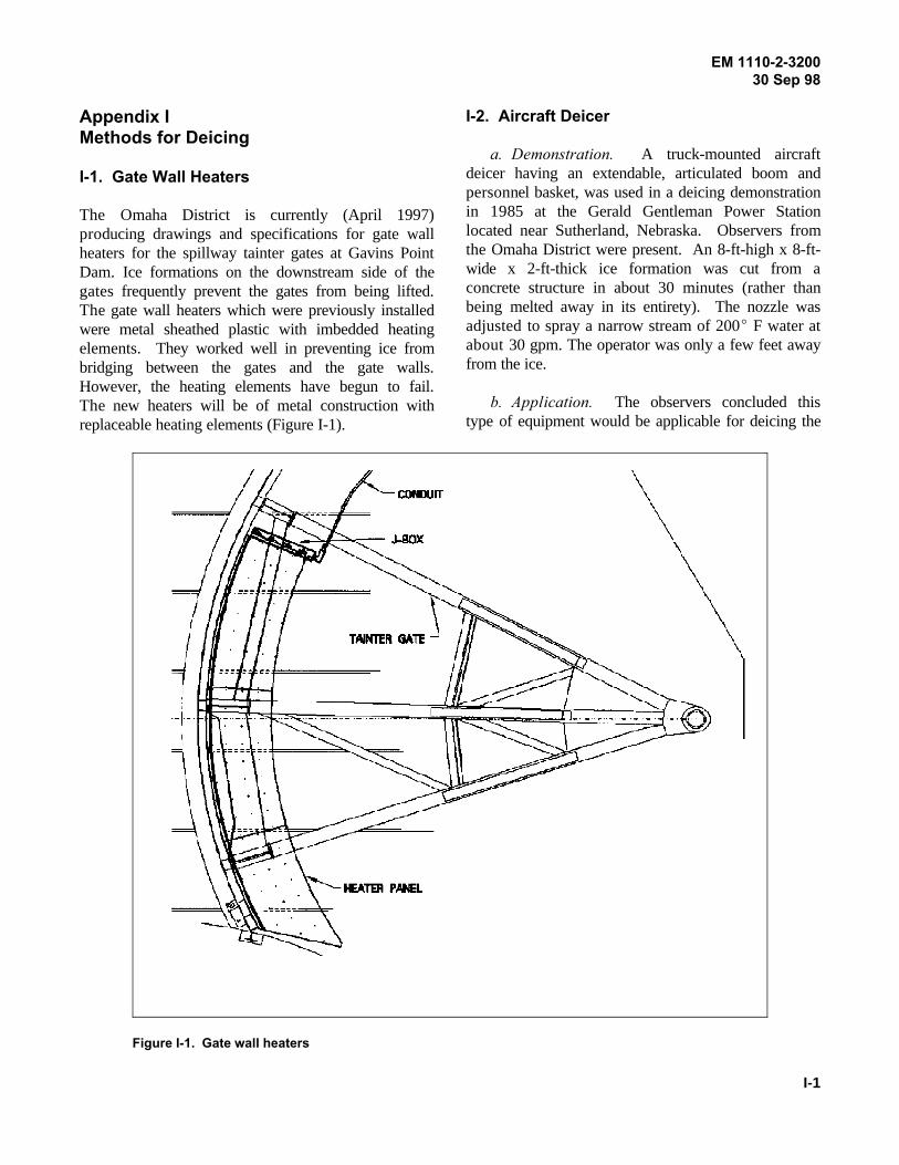
EM 1110-2-320030 Sep 98
I-1
Figure I-1. Gate wall heaters
Appendix IMethods for Deicing
I-1. Gate Wall Heaters
The Omaha District is currently (April 1997)producing drawings and specifications for gate wallheaters for the spillway tainter gates at Gavins PointDam. Ice formations on the downstream side of thegates frequently prevent the gates from being lifted.The gate wall heaters which were previously installedwere metal sheathed plastic with imbedded heatingelements. They worked well in preventing ice frombridging between the gates and the gate walls.However, the heating elements have begun to fail.The new heaters will be of metal construction withreplaceable heating elements (Figure I-1).
I-2. Aircraft Deicer
a. Demonstration. A truck-mounted aircraftdeicer having an extendable, articulated boom andpersonnel basket, was used in a deicing demonstrationin 1985 at the Gerald Gentleman Power Stationlocated near Sutherland, Nebraska. Observers fromthe Omaha District were present. An 8-ft-high x 8-ft-wide x 2-ft-thick ice formation was cut from aconcrete structure in about 30 minutes (rather thanbeing melted away in its entirety). The nozzle wasadjusted to spray a narrow stream of 200E F water atabout 30 gpm. The operator was only a few feet awayfrom the ice.
b. Application. The observers concluded thistype of equipment would be applicable for deicing the

EM 1110-2-320030 Sep 98
I-2
spillway gates at Gavins Point Dam. Provisions density polyethylene cladding, and vibrators. CRRELwould be required to station the operator close to the has done some work on gate deicing and should haveice as the water cools at a rate of about 2E F per ft advice on most of these options. For informationafter leaving the nozzle, and a narrow stream is contact:required for cutting ice. The deicing equipment couldalso be installed on a truck without the boom and Robert B. Haehnelpersonnel basket, or on a trailer, or be designed for Department of the Army, Corps of Engineersinstallation at a permanent location. Cold Regions Research and Engineering
I-3. Cold Regions Research And EngineeringLaboratory (CRREL)
Among some of the possibilities for deicing are sidepanel heaters, bubbler systems, steam boilers, high
LaboratoryHanover, New Hampshire 03755-1290Tel (603) 646-4184Fax (603) 646-4477

EM 1110-2-320030 Sep 98
J-1
Figure J-1. Drum/sheave arrangement
Appendix JSample Problem
J-1. Problem Description
A six-year-old wire rope used on a frequently usedgate-lifting device located in a warm, humid fresh-water environment is inspected. The inspectionreveals that the rope is near failing from corrosion asthere are many large corrosion pits and rusty areas.The inspection also indicates fatigue is a problem asmany broken wires are present. There is no indicationof abrasion.
J-2. Equipment Description/Analysis
a. Drum/sheave arrangement. 10-part as shownin Figure J-1.
b. Sheave pitch diameter. 45 inches.
c. Sheave bearings. Plain.
d. Maximum load (gate weight, friction drawdown, etc): 132 tons.
e. Rope: 1-1/2-in. 6x30G flattened strand, rightregular lay, improved plow steel (uncoated), IWRC.
Per Chapter 4, Figure 4-3, the dynamic rope tension is0.156 of the load for a lift mechanism with a 10-partsheave arrangement. Therefore, dynamic rope tensionwould be:
0.156 x 132 tons = 20.6 tons
Per Appendix C Table 8, the nominal strength of theexisting rope was 119 tons when new, and per Chap-ter 4, Figure 4-5, the 30:1 D/d ratio for bending overthe sheaves results in a rope efficiency of 0.95.Therefore, the factor of safety for the existing ropewhen new was:
(119 tons/20.6 tons) x .95 = 5.5 FOS
In short, the factor of safety is adequate for therequirements given in Chapter 4, Paragraph 4-5, andthe bending radius is the minimum recommended inChapter 4, Figure 4-11 (for 6x30 G Flattened Strandrope). It appears the rapid corrosion was caused bythe humid environment and fatigue resulted fromfrequent use of the gate.
J-3. Potential Solutions
a. A first thought may be to replace the existingrope with a one of a similar construction but ofstainless steel instead of improved plow steel, sinceChapter 2, Paragraph 2-5, states that “The stainlesssteels are many times more corrosion resistant than thecarbon.” However, this paragraph also states that withstainless steels a 10 to 15 percent loss in strengthshould be expected. Compared to the 5.5 factor ofsafety for the existing rope when new, a new rope ofthe same construction, but of stainless steel (with a 15percent strength reduction) would have a 4.7 factor ofsafety, which is lower than required according toChapter 4, Paragraph 4-5. In addition, the inspectionrevealed many broken wires, which is a sign offatigue. Merely changing to stainless steel would notreduce fatigue.
b. Given the same load, fatigue could be reducedby changing to lang lay construction. Per Chapter 2,Paragraph 2-2, lang lay rope has better resistance tofatigue while it is equal in strength. It tends to rotatein use, but this is not a problem if both ends areconstrained.
c. Also, fatigue could be reduced by changing toa configuration with smaller wires such as 6x37. Notethat as previously stated, the bending radius of 30:1 isthe minimum recommended for 6x30 G flattened

EM 1110-2-320030 Sep 98
J-2
strand rope. The minimum bending radius for 6x37 plain bearing sheave is 0.156 of the load. Therefore,according to Chapter 4, Figure 4-11, is 26:1. From rope tension with a plain bearing sheave is calculatedChapter 4, Figure 4-12, it would appear this increase using the following equation:from minimum could produce a significant reductionin fatigue. Normally smaller wires would increase 0.156 x 132 tons = 20.6 tons (J-1)corrosion, but in conjunction with a change tostainless steel, this would not likely be a problem. If the sheave were replaced or modified to use roller
d. A significant problem would be the loss of tension would be 0.123 of the load. Tension isstrength. A 1-1/2-inch rope of 6x37 IWRC calculated using the following:construction and of improved plow steel has anominal strength of 99 tons according to Appendix C, 0.123 x 132 tons = 16.2 tons (J-2)Table C4. This 17 percent strength reduction wouldresult in a factor of safety of 4.6 for the same rope The factor of safety for a stainless steel rope of 6x37tension. Combined with a 15 percent strength IWRC lang lay construction combined with a rollerreduction for changing to stainless steel, the factor of bearing sheave would then be as follows:safety would only be 3.9 for the same rope tension.
e. It would appear that changing to a stainlesssteel rope of 6x37 IWRC construction would solve The factor of safety of 5.8 is better than required.both the corrosion and fatigue problems except thatthe factor of safety would be lower than required. f. Further investigation would be required toNote that the sheaves use plain bearings. As stated in determine if modifying the sheaves to use rollerChapter 4, Paragraph 4-4, the rope tension for sheaves bearings is the cost effective solution. Also, beforewith plain bearings can be much higher than for proceeding with this solution, it would be wise tosheaves with roller bearings. Chapter 4, Figure 4-3, contact technical specialists at wire rope companies toshows that the rope tension for the existing 10-part see if they agreed that this is a solution to the problem.
bearings, Chapter 4, Figure 4-3, indicates the rope
(99 tons/16.2 tons) x .95 = 5.8 FOS (J-3)

EM 1110-2-320030 Sep 98
1
Index
This index is organized alphabetically by topic and bysubtopic within topic. Topics and subtopics areidentified by paragraph number unless otherwiseindicated.
Abrasive wearGeneral 2-1, 4-1Inspection 7-1
Availability 5-3
Bearing pressure 4-9
Bending radii 4-8
Blending wires 2-8
Brass wires 2-5
Break-in 6-3
Bronze wires 2-5
Carbon steel wires 2-5
Classification 2-1
Coatings 2-7
Compacted strand rope 2-3
Construction Chapter 2
Cost 5-3
Cores 2-6
CorrosionCathotic protection 7-6General 4-1Inspection 7-1Versus class 2-1Versus lay 2-2Versus material 2-5Painting 7-5
Sockets 3-1Specially shaped rope 2-3
DiameterGrooves 6-1Ropes 6-1, 7-1
Dogging device 4-4
Drum Anchorages 3-3Installation 6-3General 4-1, 4-9
Ductility, of wires 5-2
Dynamometer test 6-3
Factor of safety 4-5
Failure modes 4-1
Fatigue 2-1, 4-1
Filling with plastic 2-7
Flat rope 2-4
Fleet angle 4-10
Flattened wire rope 2-3
Flexibility and class 2-1
Flexibility and lay 2-2
Galvanizing 2-7
Handling 6-1
Ice removal 7-4
Inspection Chapter 7
Kevlar 2-5
Lay 2-2
Load calculations 4-2, 4-3

EM 1110-2-320030 Sep 98
2
Lubrication 5-2, 7-3 Proof testing 5-2
Manufacturing 2-8 Swaged 3-1
Nominal strength 4-4 Splicing 3-4
Nomenclature, standard 5-1 Stainless steel 2-5
Part-number 4-3 Storage 6-2
Peening 7-1 Strand Chapter 2(Intro.),
Pitch length 5-2
Plating 2-7
PreformingGeneral 2-8 Stretch, RopeTest for 5-2 General 4-7
Pre-stretching Elastic 4-7General 2-8 Versus life 7-1Test for 5-2
Replacement Rope 4-1
Reserve strength 4-4
Rollers 4-1
Saltwater 2-5 General 3-3
Scrubbing 7-1
Seizing 3-4
Service conditions 4-1
Service life 4-6
Sheaves General 4-1 Wire materials 2-5Efficiency loss 4-5Load calculations 4-3 X-chart 2-1
Socketing 2-8, 3-3Sockets
General Chapter 3Materials 3-2
Speltered 3-1
2-1
Stress, excessive 4-1
Stress, relieving 2-8, 5-2
Constructional 4-7
Swaged wire rope 2-3
Tensioning 2-8, 6-3
Tension Test 5-2
Terminations
Efficiency of 4-5
Torsion rest 5-2
Unreeling 6-2
Weaving 2-8
Weld distribution 5-2