distribution of electric field in capacitor and surge...
TRANSCRIPT

2012 IEEE International Conference on Power and Energy (PECon), 2-5 December 2012, Kota Kinabalu Sabah, Malaysia
Distribution of Electric Field in Capacitor and Surge Arrester Bushings
Hazlee Illias, Mohsin Ali Tunio, Ab Halim Abu Bakar, Hazlie Mokhlis Electrical Engineering Department
Faculty of Engineering, University of Malaya Kuala Lumpur, Malaysia
Abstract-The electric field distribution in high voltage capacitor
and surge arrester bushings is principally dependent on the
geometry dimension and types of the materials used. The main
target is to achieve a bushing design which has a good electric
field stress control. In this paper, two-dimensional (2D) axial
symmetrical model geometries of high voltage capacitor and
surge arrester bushings have been developed using finite element
analysis (FEA) method, which is COMSOL Multiphysics
software. These models have been used to obtain the electric field
distribution in capacitor and surge arrester bushing models. The
effects of the bushing permittivity and electrical conductivity, the
width and length and the metallic interface on the electric field
distribution in bushing structure were analysed. From this study,
an understanding of electric field distribution in bushing
geometry may be attained, which may help in designing high
voltage bushing stress control.
Keywords-electric field distribution; finite element analysis; electrical insulation
I. INTRODUCTION
A bushing consists of a long central conductor and a shorter earth flange separated by insulating material. Failure of the bushing can occur by a punctured insulating material or flashover along the external surface. A puncture depends on the radial stressing of the insulating material, while flashover occurrence depends on the axial stressing of the external surface. A capacitor-type bushing was first explained by Nagel [I]. Publications on bushing theories can be found widely in previous literature [2-7]. Most of the papers dealt briefly with a bushing having a finite number of foils.
Tasny-Tschiassny studied the theory of uniform axial gradient cases [6]. The author stated that the difference between the actual maximum radial stress for finite and infmite number of foils is not large and reduces when the number of foils is increased. As a result of this work, bushing theory with an infinite number of foils was established. The distribution of the radial stress between flange conductor was calculated and it was found that the best design was obtained when the radial stress at the conductor to flange is equal [8].
The most efficient design can be obtained when the radial and axial stressings are uniform. If the bushing consists of less than one inner conductor, earth flange and insulating material, the radial and axial stressings are far from uniform. A capacitor-type bushing improves the stressing by embodying
978-1-4673-5019-8/12/$31.00 ©2012 IEEE 973
cylinders of metallic foil in the insulating material. These cylinders are concentric with the central conductor and flange. Without the foils, most of the electric flux passing between the central conductor and earth flange is concentrated over a length equals to that of the earth band. A capacitive field calculation in a capacitor bushing was reported by Mukherjee and Roy [9]. The electric field calculations in and around HV bushings were done with the help of numerical methods.
Bushing also plays an important role in surge arresters. One of the surge arrester widely used is Zinc-Oxide (ZnO). For a surge arrester, the potential gradient will not be unifonn owing to the stray capacitances to ground. The stray capacitances become more significant as the height of the arrester increases. In station-class arresters, this would lead to the voltage distribution across the elements becomes non unifonn, where a significant proportion of the arrester voltage is across the upper elements [10]. Grading elements such as grading rings, capacitive elements and resistive elements have been employed to mitigate the effects of stray capacitances. Non uniformity of the voltage distribution may be a significant factor in reducing the stability or reliability and the lifetime of surge arresters.
Many publications on modelling of ZnO surge arresters have been widely published. Csendes described the formulation of a finite-element model for electrostatic solutions in which they developed a ballooning technique to solve the problem of open boundaries and used a special routine based on the energy in the electric field to determine the capacitances [11]. Oyamahas used finite-element computation to determine the voltage distribution on a 500 kV surge arrester by taking into account the floating electrodes at the arrester flanges [12]. Peibai formulated a finite-element model which accounts for the floating electrodes and open boundary conditions [13]. The model was used to show the non-uniform voltage distribution on 220 and 500 kV surge arresters.
In this work, two-dimensional (2D) axial-symmetrical model geometries of high voltage capacitor and ZnO surge arrester bushings have been developed using finite element analysis (FEA) software to study the electric field distribution. The models were also used to study the effects of the bushing permittivity and electrical conductivity, the width and length and the metallic interface on the electric field distribution in bushing structure were analysed. This may help in bushing designing in reducing the electric field stress.

2012 IEEE International Conference on Power and Energy (PECon), 2-5 December 2012, Kota Kinabalu Sabah, Malaysia
II. FEA MODELS
Figures 1 and 2 show 2D axial symmetric model geometry of capacitor and ZnO surge arrestor bushings that has been developed using FEA software. The total length of the capacitor bushing is 163 mm, the diameter of the conductor is 4 mm, the diameter of the longer bushing plate is 50 mm and the diameter of the shorter bushing plate is 40 mm. For the ZnO surge arrester bushing, the total length of the structure is 420 mm, the diameter of the conductor is 24.5 mm and the larger diameter of the bushing plate is 250mm and smaller diameter of the bushing plate is 208mm. The applied voltage across the conductor is 132 kV. The bushings were surrounded by a layer of air to simulate the electric field distribution along the outer surface of the bushings. Table 1 shows the dielectric constants for each component used in the models.
The module used in COMSOL Multiphysics was ACIDC module, electrostatic model to obtain the electric field distribution in the model. After the model was drawn completely, the permittivity and electrical conductivity were assigned to the model, using the values shown in Table 1. Then, the boundary conditions were assigned on the model. The conductor was assigned with the electric potential, the air boundary with ground, aluminium cap with floating potential and the rest of the boundaries were assigned with continuity. The model was meshed and finally, the model was solved for its electric potential distribution in the geometry.
The electric field distribution in the FEA model is obtained by solving the electric potential. The electric potential equation is described by the field model. The equation used by the FEA software to solve the electric potential in the model is
- - - a -- v e(aVV)- V e-(eVV) = 0 at
(I)
TABLE!. PARAMETERS FOR EACH COMPONENT IN THE MODELS
Material Permittivity Electrical condnctivity, Sm" Air I 0
Aluminium 1 1 x 10' Conductor I 6 x 10⁷
Silicon Oil 2.5 0 Porcelain 5.1 0
XLPE 2.2 0 Poly-propylene 3.9 0
Glass fibre 4.6 0 Zinc Oxide 60 0
III. FEA SIMULATION RESULTS
A. Electricfield distribution Figure 3 shows the simulated electric field distribution in
the capacitor bushing model geometry shown in Figure 1. The maximum electric field is obtained at the edge of the aluminium cap because it is a floating potential boundary. The electric field decreases when it is further from the conductor due to the presence of different insulation material permittivity.
974
-1+-'::::""",--Silicol1 oil I .J--!-k==-- XLPE
IH-+l'--=-- Col1ductor
Figure I. 20 axial-symmetric capacitor bushing model geometry using FEA
rr-r-,l----- A1uminium terminal block
�::��- Poly-ProP)'lene housing
1 -+---- Glass libel" encapsllllalion
Metallic interfaces
--+--F""--...=--- Zinc Oxide
I!----!-f:===� Conductor
Figure 2. 20 axial-symmetric ZnO surge arrester model geometry using FEA
Figure 4(a) shows the simulated electric field in surge arrester bushing from the model geometry shown in Figure 2. It can be seen that in Figure 4 (a), the electric field distribution is not uniform, especially at the edges of the bushing and at the aluminium cap. This is due to the difference in the permittivity of the bushing plate and the air surrounding it. Figure 4 (b) shows the electric field simulation of the surge arrester bushing without the metallic interfaces to investigate the effect of this component. The electric field at the edges of the bushing is

2012 IEEE International Conference on Power and Energy (PECon), 2-5 December 2012, Kota Kinabalu Sabah, Malaysia
slightly reduced and less concentrated compared to the presence of the metallic interfaces. However, the metallic interfaces can reduce the likelihood of corona and surface discharges along the bushing surface due to its higher conductivity than the surrounding material.
540
520
500
E ,S480
(f) .;;;: ro 460
N 440
420
400
Ti m .=0 .005 Surf ace: Electr ic fi eld, norm [V 1m] ,-----,,..
·20 20 40 60 80 100 120 140 160 180 200 Min� 0
r- axis (mm) Figure 3. Simulated electric field distribution in capacitor bushing model
B. Cross section plots of electric field magnitude The cross-section plots of the electric field magnitude along
the z = 473.5 mm line in capacitor and z = 299 mm in surge arrester models are shown in Figures 5 and 6. The cross-section plot of the electric field magnitude is not uniform. This is due to the different materials in the structure, which have different permittivity and boundary condition. The electric field is the highest at the region nearest to the conductor but decreases within the insulation material at the location further from the conductor, except for the surge arrester. Referring to Figure 5, after the first and second layers of insulation material, the electric field is almost uniform within the region of the porcelain bushing. There is discontinuous electric field between the porcelain bushing and the layer next to it, which is air, due to the permittivity difference between the porcelain and aIr.
Referring to Figure 6, the electric field in the surge arrester is low in the region after the conductor because a very high permittivity of zinc oxide in the surge arrester keeps the electric field low at the region after the conductor. The next layer after the zinc oxide is the glass fibre, which is surrounded by polymeric bushing. There is a discontinuity in the electric field between the regions of zinc oxide and glass fibre due to the permittivity difference. The next layer after the glass fibre is air, where the electric field decreases when it further from the surge arrester.
975
400
250
200
·50
400
�350 E .§. II) 'x. Ol' N 300
250
200
·50
Time=0,005 Surfac.: Electric field, norm [VIm]
50 100 150
r- axis (mm) (a)
Tlme=0,005 Surface: Electric field, norm [Vim]
50 100 150
r· axis (mm)
(b)
200 250
200 250
Max: 7145.245 7000
6000
5000
4000
3000
2000
1000
Max: 5487.235
5000
4500
4000
3500
3000
2500
2000
1500
1000
500
Min: a
Figure 4. Simulated electric field distribution in surge arrester bushing model (a) with and (b) without metallic interfaces
O,g l O,8 � 0,7
g 0.6
�" 0.5 0.:
CJ 0.4 ·c � 0.3
j;;i 0,2
0,1
10 20 30 40
r[mm] 50 60
Figure 5. Cross-section plot of the electric field magnitude along the z = 473.5 mm line in capacitor bushing
2012 IEEE International Conference on Power and Energy (PECon), 2-5 December 2012, Kota Kinabalu Sabah, Malaysia
3500 r---,---,----,---,---,---,---,----,---,----,------,
1 3000
G � 2500
o c
:;'"' 2000
II:l u :.s 1 500 u '"
1il 1 000
500
o L-�-��-����-��-��� o 10 20 30 40 70 80 90 100 110 r[mm]
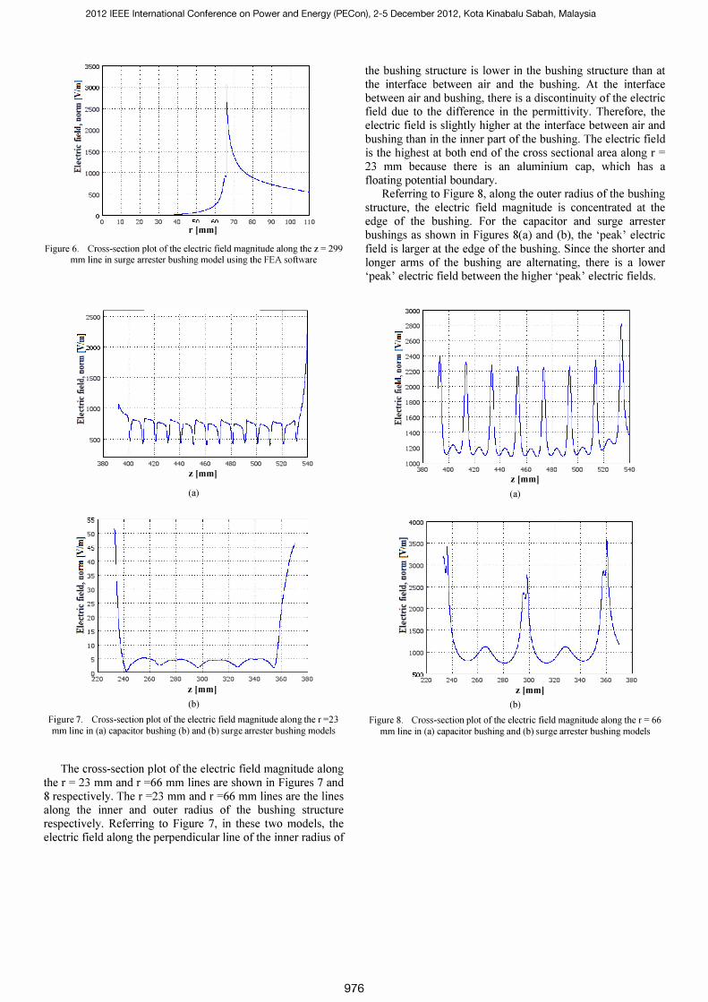
Figure 6. Cross-section plot of the electric field magnitude along the z = 299 mm line in surge arrester bushing model using the FEA software
2500
1 t::.J ooo
� o c ·,:P500 -.; II:l
u . ;: tj 1000 . .. 1il
500
380 400 420 440 460 480 500 520 540
zlmm] (a)
55,--,--,----,-----,---,,---,--,--,
50 .
l 45
� 40 . g 35 .
� 30
II:l C"iJ 25 . . ;: "'t 20 . '"
1il 1 5
1 0 .
5 .
�20 240 260 280 300 320
zlmm] (b)
340 360 380
Figure 7. Cross-section plot of the electric field magnitude along the r =23 mm line in (a) capacitor bushing (b) and (b) surge arrester bushing models
The cross-section plot of the electric field magnitude along the r = 23 mm and r =66 mm lines are shown in Figures 7 and 8 respectively. The r =23 mm and r =66 mm lines are the lines along the inner and outer radius of the bushing structure respectively. Referring to Figure 7, in these two models, the electric field along the perpendicular line of the inner radius of
976
the bushing structure is lower in the bushing structure than at the interface between air and the bushing. At the interface between air and bushing, there is a discontinuity of the electric field due to the difference in the permittivity. Therefore, the electric field is slightly higher at the interface between air and bushing than in the inner part of the bushing. The electric field is the highest at both end of the cross sectional area along r = 23 mm because there is an aluminium cap, which has a floating potential boundary.
Referring to Figure 8, along the outer radius of the bushing structure, the electric field magnitude is concentrated at the edge of the bushing. For the capacitor and surge arrester bushings as shown in Figures 8(a) and (b), the 'peak' electric field is larger at the edge of the bushing. Since the shorter and longer arms of the bushing are alternating, there is a lower 'peak' electric field between the higher 'peak' electric fields.
3000 ,----,---,----,------,------,------,--,-------,
2800
� 2600
� 2400 .
o Ii:! 2200 .
::f � 2000 .
u .;: 1800 tl � 1600 .
1400 .
1200
1000 L-_-'---_-'---_--'---_---'--_�_----' __ �-----' 380 400 420 440 460 480 500 520 540
z[mm] (a)
4000 r---,---,--,--�----,-�----',---,-------,
83500
� � 3000 o c :.f 2500 .
'" II:l . � 2000 .
tl '"
1il 1500 .
1000
500 L-_�_�_�_�_�_� __ �-----'
220 240 260 280 300 320 340
z lmm] (b)
360 380
Figure 8. Cross-section plot of the electric field magnitude along the r = 66 mm line in (a) capacitor bushing and (b) surge arrester bushing models

2012 IEEE International Conference on Power and Energy (PECon), 2-5 December 2012, Kota Kinabalu Sabah, Malaysia
C. Electricfield magnitude as a function of material permittivity Figure 9 shows the electric field magnitude at a certain
point within the bushing material as a function of the bushing material permittivity for capacitor and surge arrester bushing models using the FEA software. When the permittivity, E: of the bushing material in all models is higher, the electric field magnitude within the bushing, E decreases. This is because the electric field can be aligned easier within the material, resulting in less field concentration.
700
MQ�--�----�--�----�----�--�
Figure 9. Graph of electric field magnitude as a function of bushing material permittivity for (a) capacitor bushing and (b) surge arrester bushing
D. Electricfield magnitude as a function of material conductivity The electric field magnitude at a certain point within the
bushing material as a function of the bushing material conductivity for surge arrester and capacitor bushing models using the FEA software is shown in Figure 10. [f the conductivity, a of the bushing material in all models is higher, the electric field magnitude within the bushing, E decreases. An increase in the material conductivity could be due contamination or aging of the material itself.
977
75 0
700
6' � 650 '; � 600 '" " E 550 " "
i::l 500
450
400
2.3
2.2 6' � 2.1
.::: , " -r:;; " 1.9 E � 1.8
i::l 1.7
1.6
1.5
1.4
10.11
10.11
•
10.1' 10" 10�
Electric Conductivity IS/m I (a)
.
10.1• 10" 10�
Electric Conductivity [SimI (b)
Figure 10. Graph of electric field magnitude as a function of bushing material conductivity for (a) capacitor bushing and (b) surge arrester bushing
E. Electricfield magnitude as a function of width and length of bushing Figure 1 [(a) shows a graph of the electric field magnitude,
E at certain point within the bushing as a function of the bushing plate width, y for the surge arrester bushing. [t is found that the electric field at certain point in the bushing increases with the bushing plate width. When the bushing plate width increases, the interface region between air and the outer surface of the bushing structure is smaller. Therefore, this reduces the lower electric field region, which is found along the interface region between air and the outer surface of the bushing structure. This results in the electric field at certain point in the bushing is higher for larger bushing plate.
Figure 1 [(b) shows a graph of the electric field magnitude, E at certain point in the bushing as a function of bushing plate length, fJ. It can be seen that the electric field magnitude at certain point within the bushing decreases with the bushing plate length. As was shown earlier, the 'peak' electric field is obtained at each edge of the bushing. When the bushing plate length is larger, the edge of the bushing plate is further from the bushing internal structure. Thus, the electric field at certain point within the internal bushing structure is lower.

2012 IEEE International Conference on Power and Energy (PECon), 2-5 December 2012, Kota Kinabalu Sabah, Malaysia
e --
� "'CI 'Ql I::l u :.5 (.l d.1
�
S OQC----.-------------.----..------::IIJ
11 u 1� IS 1,0 Width Imml
(a)
8 9 10 Length [mm]
(b)
".�, :4
Il
Figure 11. Graph of electric field magnitude as a function of bushing plate (a) width and (b) length
IV. CONCLUSION
[n this paper, two-dimensional (2D) axial-symmetrical model geometries describing high voltage capacitor and surge arrestor bushings have been successfully developed using finite element analysis (FEA) software. The models were able to simulate the electric field distribution in capacitor and surge arrestor bushings. [t was found that the electric field distribution is influenced by many factors. These include the porcelain bushing permittivity and electrical conductivity, width, length and the metallic interface. From the simulation results, the electric field magnitude within the porcelain bushing decreases exponentially with the permittivity and electrical conductivity of the bushing material. These results show that the bushing structure and material type play an important role in the electric field stress control within the bushing. By varying the plate width and length of the bushing, it was found that the electric field at certain point in the bushing is higher for larger bushing plate but lower for a larger length of the bushing. Although the electric field was able to be simulated by FEA, the time taken for computation is considerably long due to the fine meshing structure used.
978
ACKNOWLEDGMENT
The author thanks the University of Malaya for supporting this work through the H[R research grant (Grant no: H-[600[OO-D000048).
[I]
[2]
[3]
[4]
[5]
[6]
[7]
[8]
[9]
[10]
REFERENCES
R. Nagel, "Uber eine Neuerung an Hochspannungs transfonnatoren der Siemens- chuckertwerke G.m.b.H," Elektrische Bahnen und Betriebe, vol. 4, p. 275, 1906.
K. Humburg, "Die Berechnung von Kondensatordurchfiihrungen " Archiv fur Elektrotechnik, vol. 12, pp. 526- 545,1923.
A. Imhof, " Beitrag zur technischen Berechnung von KondensatorDurchfuhrungen," Schweizer Elektrotechnischer Verein, vol. 17, p. 586, 1926.
H. Einhorn, "Zweckmassige Formgebung von Kondensatordurchfuhrungen," Elektrotechnisehe Zeitschrift, vol. 53, p. 153,1932.
B. L. Goodlet, "The Design of Condenser Type Bushing Insulators," World Power, vol. 23, p. 8, 1935.
1. Tasny-Tschiassny, "The Design of Condenser Bushings and their Most Economical Dimensions," British Plastics, vol. II, p. 212,1939.
F. Cerovsky, "Nomogram for the Calculation of Condenser Bushings," Engineers Digest, vol. 10, pp. 197-199, 1949.
W. J. John and M. M. Sakr, "Capacitor Bushing Theory," Proceedings of the lEE - Part IV: Institution Monographs, vol. 101, p. 91,1954.
P.K.Mukhe�jee and C.K.Roy, "Computation of Electric Field in a Condenser Bushing by Fictitious Area Charges," 4th Int Symp on HV Engg, Athens, vol. 12,1983.
N. Alame and G. Melik, "Axial voltage gradient distribution of metal oxide surge arresters " Proceedings of the 3rd international conference on Properties and applications of dielectric materials, Tokyo, pp. ll49-ll51, July 1991.
[ll] z. 1. Csendes and 1. R. Hamann, "Surge arrester voltage distribution analysis by the finite element method," IEEE Transactions, vol. 100, pp. 1806-1813,1981.
[12] M. Oyama, et aI., "Analytical and experimental approach to the voltage distribution on gapless zinc-oxide surge arresters," IEEE Transactions, vol. PAS-I 00, pp. 4621- 4627, 1981.
[13] Z. Peibai, et aI., "Analysis of the potential distribution of gapless surge arresters," Proceedings of the 6th international symposium on: High voltage engineering, New Orleans, Louisiana, vol. 2,1989.