distribution level phasor measurement accuracy limits - jeff zhao
TRANSCRIPT

Distribution Level Phasor Measurement Accuracy Limits
Jiecheng (Jeff) Zhao, Lingwei (Eric) Zhan, Yilu Liu
University of Tennessee, Knoxville Paul Ewing, Joe Gracia
Oak Ridge National Laboratory March 23, 2015

Outline
Introduction
Methodology
Error Analysis
Conclusions
2

Introduction
Looking beyond wide area monitoring Potential value with more generation and load control
at distribution level Measurement accuracy and error impact are issues –
no standard for distribution level measurements Focused on frequency and phase angle
3
FDR (Frequency Disturbance Recorder)
PMU (Phasor Measurement Unit)
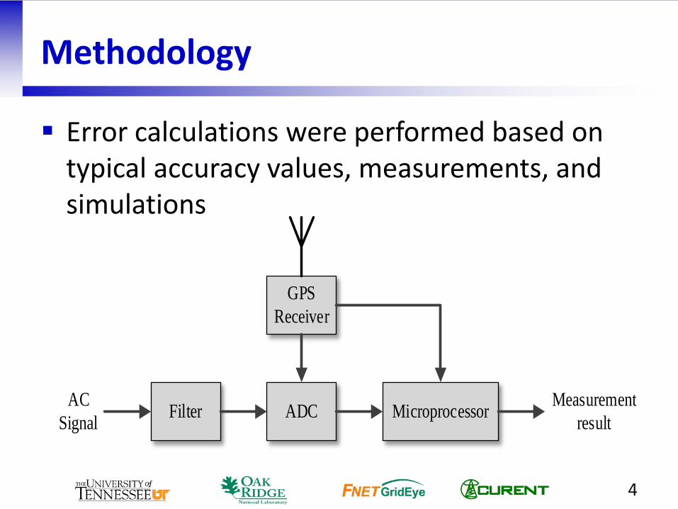
Methodology
Error calculations were performed based on typical accuracy values, measurements, and simulations
4
Filter ADC Microprocessor
GPSReceiver
AC Signal
Measurement result

Methodology
Error sources vary – both internal and external
5
Error Sources
Internal factor
External factor
Hardware
Software
Time reference
ADC
Noise inside device
Round error
Algorithm
Noise
Harmonic distorion
White noise
Other noise

Methodology
• Our focus was on errors with larger impact
6
Error Sources
Internal factor
External factor
Hardware
Software
Time reference
ADCNoise inside
device
Round error
Algorithm
Noise
Harmonic distorion
White noiseOther noise

Internal Factors
Main factors
Algorithms
Time reference
ADC
Approach
Calculations based on typical inaccuracies
Simulation
7

Algorithm Error
Fed digitized sinusoidal signal with known frequency, amplitude, and angle into measurement algorithm Measurement algorithm -Discrete Fourier
Transform (DFT) Error obtained by comparing estimated values
and true values Increased simulation time (resampling) until
max positive and negative error converged
8

Algorithm Error
• Result - Sensitive to frequency deviation
9
0.00E+001.00E-072.00E-073.00E-074.00E-075.00E-076.00E-077.00E-078.00E-07
0.00E+002.00E-044.00E-046.00E-048.00E-041.00E-031.20E-03
59.95 59.975 60 60.025 60.05
Freq
uenc
y Er
ror (
Hz)
Angl
e Er
ror (
degr
ee)
Actual Frequency (Hz)
Angle Error Frequency Error

Time Reference Error
• GPS: 1 sec time/frequency reference • PPS signal: typical jitter - 50 ns to 1 μs; held to
10 ns with effort
10
Amplitude
Time
GPS Second
GPS Receiver PPS Signal

Time Reference Error
• Result (f = 59.95 Hz) – jitter matters
11
0.00E+001.00E-052.00E-053.00E-054.00E-055.00E-056.00E-057.00E-05
0.00E+00
5.00E-03
1.00E-02
1.50E-02
2.00E-02
2.50E-02
10 ns 50 ns 1 μs
Freq
uenc
y Er
ror (
Hz)
Angl
e Er
ror (
degr
ee)
Time reference Error
Angle Error Frequency Error

ADC Error • Results (f = 59.95 Hz) – better resolution helps • 1 least significant bit (LSB) error
12
0.00E+00
5.00E-05
1.00E-04
1.50E-04
2.00E-04
2.50E-04
0.00E+001.00E-032.00E-033.00E-034.00E-035.00E-036.00E-03
14 bit 16 bit
Freq
uenc
y Er
ror (
Hz)
Angl
e Er
ror (
degr
ee)
ADC Accuracy
Angle Error Frequency Error
External Factors
Main factors • White noise • Harmonic distortion
Approach • Measure the real noise level • Simulation • f=59.95 Hz
13

White Noise
14
0.00E+001.00E-042.00E-043.00E-044.00E-045.00E-046.00E-04
0.00E+00
5.00E-03
1.00E-02
1.50E-02
2.00E-02
70 dB 80 dB 90 dB
Freq
uenc
y Er
ror (
Hz)
Angl
e Er
ror (
degr
ee)
SNR (Signal-to-Noise Ratio) Angle Error Frequency Error
• Result (f = 59.95 Hz) – SNR matters • Four cases – calculated power spectrum densities
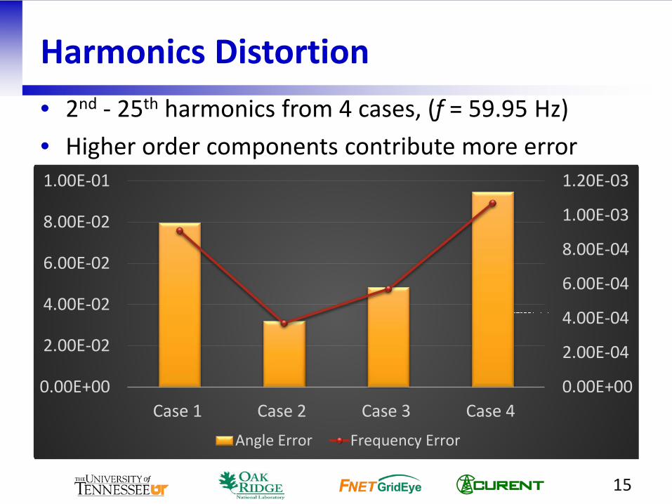
Harmonics Distortion • 2nd - 25th harmonics from 4 cases, (f = 59.95 Hz) • Higher order components contribute more error
15
0.00E+00
2.00E-04
4.00E-04
6.00E-04
8.00E-04
1.00E-03
1.20E-03
0.00E+00
2.00E-02
4.00E-02
6.00E-02
8.00E-02
1.00E-01
Case 1 Case 2 Case 3 Case 4Angle Error Frequency Error

Angle Error Contribution
• f = 59.95 Hz
16
0.00E+00
1.00E-02
2.00E-02
3.00E-02
4.00E-02
5.00E-02
6.00E-02
7.00E-02
8.00E-02
9.00E-02
1.00E-01
Algorithm GPS ADC White Noise HarmonicDistortion
59.95Hz
10ns 14bit 70dB
Case 1
59.975Hz
50ns 16bit 80dB
Case 2
60Hz 1µs
90dB
Case 3
60.025Hz
Case 4
60.05Hz
Angle Error Contribution of Each Factor (degree)
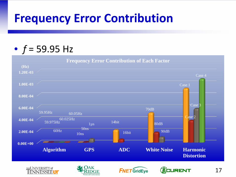
Frequency Error Contribution
• f = 59.95 Hz
17
0.00E+00
2.00E-04
4.00E-04
6.00E-04
8.00E-04
1.00E-03
1.20E-03
Algorithm GPS ADC White Noise HarmonicDistortion
59.95Hz
10ns
14bit
70dB
Case 1
59.975Hz 50ns
16bit
80dB
Case 2
60Hz
1µs
90dB
Case 3
60.025Hz
Case 4
60.05Hz
Frequency Error Contribution of Each Factor (Hz)

Thank You!
Questions/Comments?