distribution automation solution - deutsche messe...
TRANSCRIPT
Distribution Automation Solution
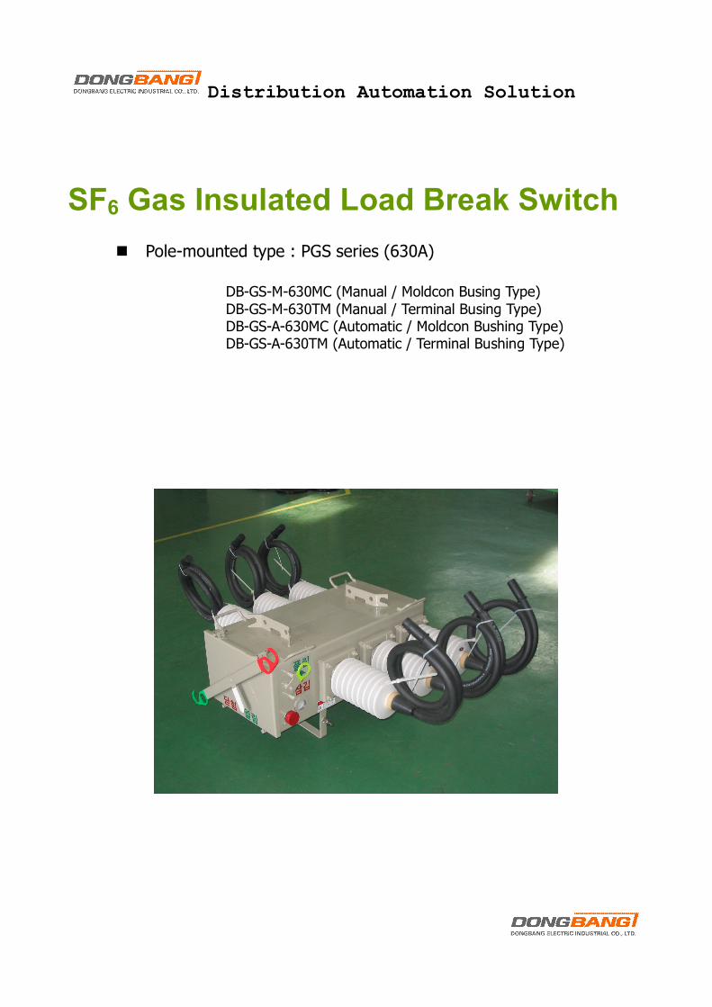
SF6 Gas Insulated Load Break Switch
n Pole-mounted type : PGS series (630A)
DB-GS-M-630MC (Manual / Moldcon Busing Type) DB-GS-M-630TM (Manual / Terminal Busing Type) DB-GS-A-630MC (Automatic / Moldcon Bushing Type) DB-GS-A-630TM (Automatic / Terminal Bushing Type)
2
Overview
SF6 gas Insulated Load Break Switch (LBS) for overhead lines operates at a voltage up to 24kV. It meets the demand for oil-less and maintenance free operation with SF6 gas, the related parts and devices installed inside its hermetically sealed stainless steel tank. The pole-mounted LBS can be manually or motorized operated for fault isolation, remote control and automation to suit your power line requirements. The pole-mounted LBS has been fully certified in accordance with ANSI C37.71 IEC 60694(1996), IEC 60265(1998) to meet and exceed customer’s requirements.
General Specification
Description 24 kV class
Operating Method Auto/Motorized/Manual
Rating
Voltage 24 kV
Current 400 A/630A
Frequency 50 Hz
Short time Withstand Current (1 sec) 12.5 kA
Making Capacity (peak) 32.5 kA
Number of Making 5 times
Breaking Capacity
Mainly Active Load Breaking 400 A/630A
Loop Current Breaking 400 A/630A
Transformer Magnetizing Current 14 A
Cable Charging Current (rms. Sym) 25 A
Line Charging Current 1.5 A
Impulse Insulation Level (1.2x50 ㎲)
Phase to Earth 150 kV
Across Interrupter 150 kV
Power Frequency Insulation Level
Phase to Earth 60 kV
Across Interrupter 60 kV
Control Source Voltage AC 240/DC 24 V
Rated Gas pressure at 20℃ 6.5 kgf/㎠G
Endurance With Current (at rated current) 200 times
Without Current 5000 times
Weight Switch Body without Mounting Frames 130 kg (Auto-type)
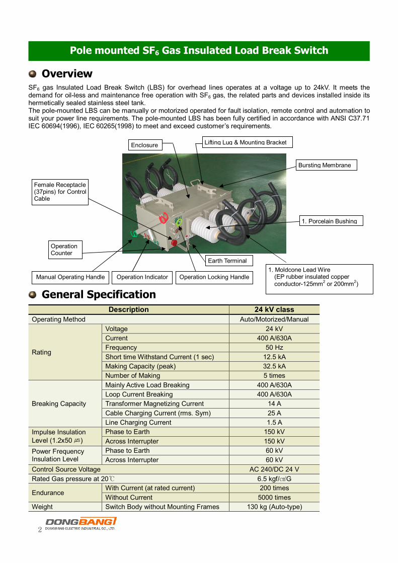
Pole mounted SF6 Gas Insulated Load Break Switch
1. Porcelain Bushing
1. Moldcone Lead Wire (EP rubber insulated copper conductor-125mm2 or 200mm2)
Lifting Lug & Mounting Bracket Enclosure
Operation Indicator Manual Operating Handle Operation Locking Handle
Earth Terminal
Female Receptacle (37pins) for Control Cable
Bursting Membrane
Operation Counter
Control Box
Construct
n All-in One Design for Distribution Automation System (DAS) Ø 3 CT's and 6 Voltage Sensors are all fitted in DB-GS-A (Automatic type only) switching tank. These make DB-
GS-A Switch to be easily applicable to DAS or SCADA System without any extra costs. Ø DB-GS-A can be directly connected to control for remote control and tele-monitoring through DAS or locally
operated by manual handle or motorized mechanism. n Oil-less, Maintenance Free
Ø SF6 gas as an insulating and interrupting medium eliminates the necessity for periodical oil maintenance.
n Robustness and Long Life Ø Stainless steel tank case with more than 3 mm thickness
is designed for its maximum robustness and minimum welding line to minimize corrosion.
Ø The robust ‘tulip’ type contact made of copper-tungsten tips ensures long contact life.
Ø Advanced TIG welding technique on stainless steel tank and double sealing technique with EPDM rubber for bushing mounting shows 0.02% gas leakage rate per year.
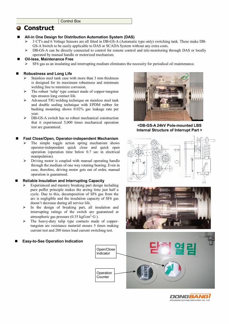
Ø DB-GS-A switch has so robust mechanical construction that it experienced 5,000 times mechanical operation test are guaranteed. <DB-GS-A 24kV Pole-mounted LBS
Internal Structure of Interrupt Part >
n Fast Close/Open, Operator-independent Mechanism Ø The simple toggle action spring mechanism shows
operator-independent quick close and quick open operation (operation time below 0.7 sec in electrical manipulation).
Ø Driving motor is coupled with manual operating handle through the medium of one way rotating bearing. Even in case, therefore, driving motor gets out of order, manual operation is guaranteed.
n Reliable Insulation and Interrupting Capacity Ø Experienced and mastery breaking part design including
pure puffer principle makes the arcing time just half a cycle. Due to this, decomposition of SF6 gas from the arc is negligible and the insulation capacity of SF6 gas doesn’t decrease during all service life.
Ø In the design of breaking part, all insulation and interrupting ratings of the switch are guaranteed at
atmospheric gas pressure (0.35 kgf/cm2·G ). Ø The heavy-duty tulip type contacts made of copper-
tungsten arc resistance material ensure 5 times making current test and 200 times load current switching test.
n Easy-to-See Operation Indication
Operation Counter
Open/Close Indicator
4
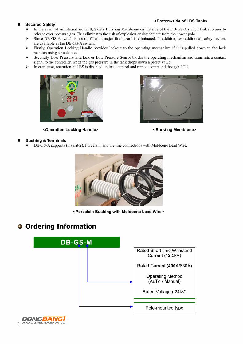
n Secured Safety
Ø In the event of an internal arc fault, Safety Bursting Membrane on the side of the DB-GS-A switch tank ruptures to release over-pressure gas. This eliminates the risk of explosion or detachment from the power pole.
Ø Since DB-GS-A switch is not oil-filled, a major fire hazard is eliminated. In addition, two additional safety devices are available in the DB-GS-A switch.
Ø Firstly, Operation Locking Handle provides lockout to the operating mechanism if it is pulled down to the lock position using a hook stick.
Ø Secondly, Low Pressure Interlock or Low Pressure Sensor blocks the operating mechanism and transmits a contact signal to the controller, when the gas pressure in the tank drops down a preset value.
Ø In each case, operation of LBS is disabled on local control and remote command through RTU.
n Bushing & Terminals
Ø DB-GS-A supports (insulator), Porcelain, and the line connections with Moldcone Lead Wire.
Ordering Information
<Bursting Membrane> <Operation Locking Handle>
<Porcelain Bushing with Moldcone Lead Wire>
DB-GS-M Rated Short time Withstand
Current (12.5kA)
Rated Current (400A/630A)
Operating Method (AuTo / Manual)
Rated Voltage ( 24kV)
Pole-mounted type
<Bottom-side of LBS Tank>
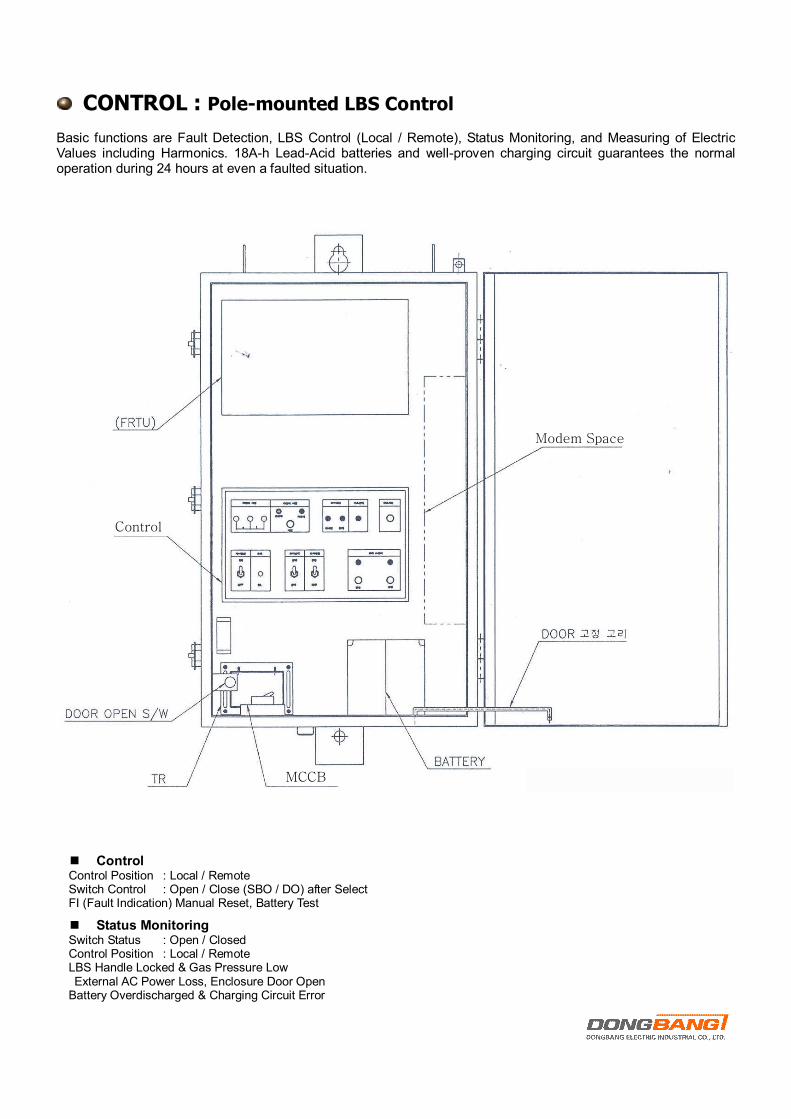
CONTROL : Pole-mounted LBS Control
Basic functions are Fault Detection, LBS Control (Local / Remote), Status Monitoring, and Measuring of Electric Values including Harmonics. 18A-h Lead-Acid batteries and well-proven charging circuit guarantees the normal operation during 24 hours at even a faulted situation.
n Control Control Position : Local / Remote Switch Control : Open / Close (SBO / DO) after Select FI (Fault Indication) Manual Reset, Battery Test
n Status Monitoring Switch Status : Open / Closed Control Position : Local / Remote LBS Handle Locked & Gas Pressure Low External AC Power Loss, Enclosure Door Open
Battery Overdischarged & Charging Circuit Error
Control
MCCB
Modem Space
6
System Error (Self Diagnosis Result) Control Cable Disconnected : optional
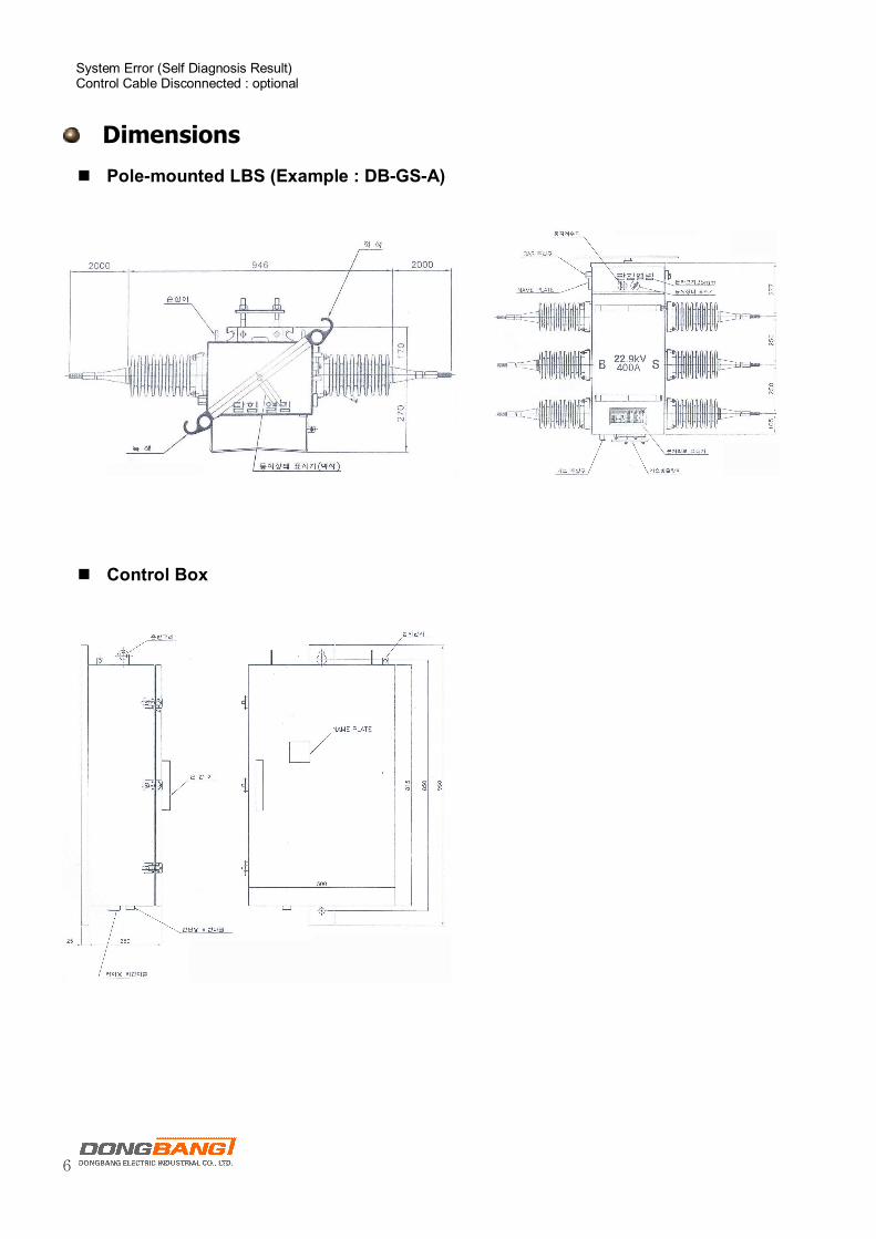
Dimensions
n Pole-mounted LBS (Example : DB-GS-A)
n Control Box
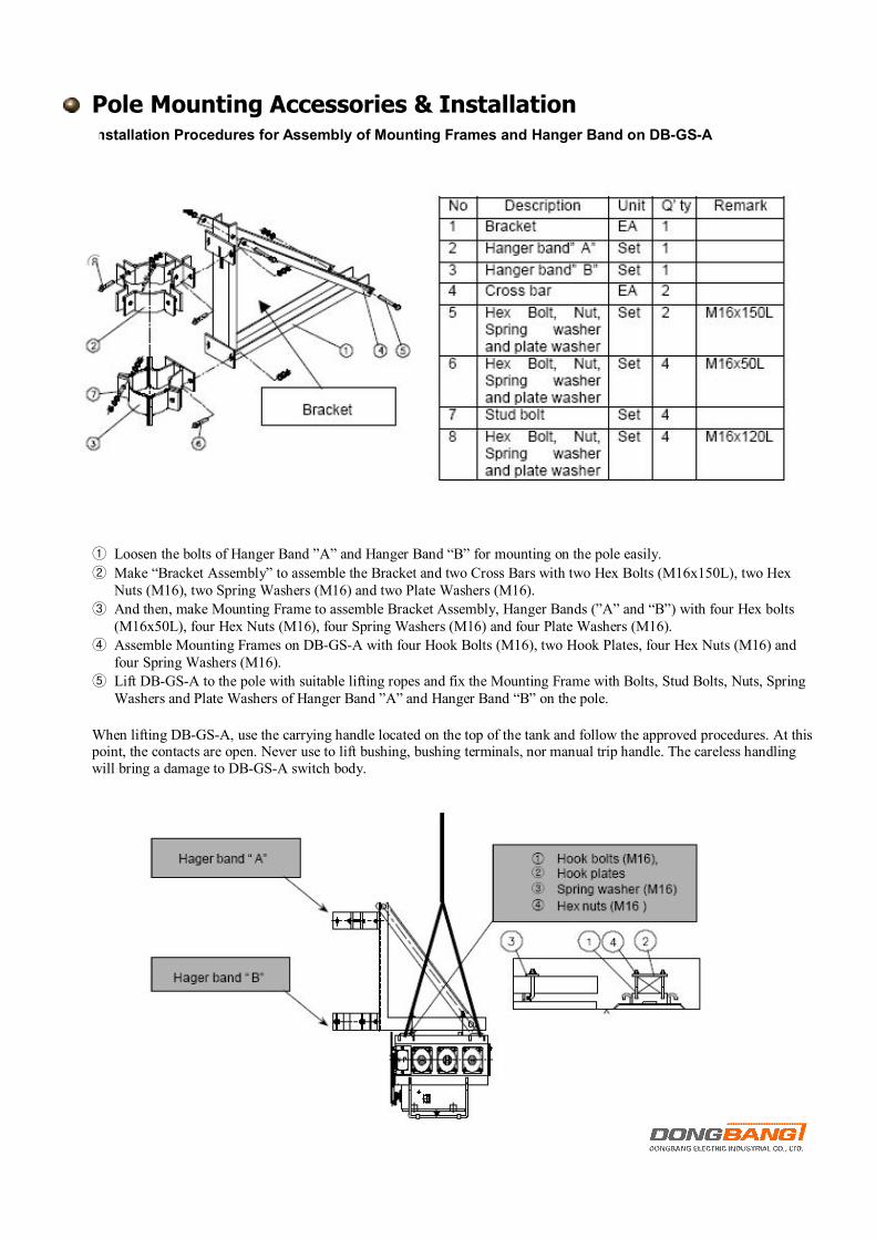
Pole Mounting Accessories & Installation
n Installation Procedures for Assembly of Mounting Frames and Hanger Band on DB-GS-A
① Loosen the bolts of Hanger Band ”A” and Hanger Band “B” for mounting on the pole easily.
② Make “Bracket Assembly” to assemble the Bracket and two Cross Bars with two Hex Bolts (M16x150L), two Hex Nuts (M16), two Spring Washers (M16) and two Plate Washers (M16).
③ And then, make Mounting Frame to assemble Bracket Assembly, Hanger Bands (”A” and “B”) with four Hex bolts (M16x50L), four Hex Nuts (M16), four Spring Washers (M16) and four Plate Washers (M16).
④ Assemble Mounting Frames on DB-GS-A with four Hook Bolts (M16), two Hook Plates, four Hex Nuts (M16) and four Spring Washers (M16).
⑤ Lift DB-GS-A to the pole with suitable lifting ropes and fix the Mounting Frame with Bolts, Stud Bolts, Nuts, Spring Washers and Plate Washers of Hanger Band ”A” and Hanger Band “B” on the pole.
When lifting DB-GS-A, use the carrying handle located on the top of the tank and follow the approved procedures. At this point, the contacts are open. Never use to lift bushing, bushing terminals, nor manual trip handle. The careless handling will bring a damage to DB-GS-A switch body.

8
n Removal of Bushing Protection Covers If bushing protection covers are not removed, the protection covers will cause a line fault. These covers are attached to prevent the bushings from damage in transportation and installation.
n Pole Mounting of Control Box Mount the control box in a convenient, accessible location with two Hanger Bands, two Hex Bolts (M16), two Hex Nuts (M16) and two Spring Washers (M16), such as suitable bands or brackets. For pole-mounted installation, a hole and keyway in the control-mounting bracket accommodates a M16 bolt.
n Grounding DB-GS-A and Control Box To make grounding to the earth terminal of DB-GS-A and control box, ① Grounding DB-GS-A
Make ground connections to DB-GS-A ground connector located on the side of front leg of DB-GS-A. It will accommodate 22mm2 to 60mm2 steel ground connector with solderless clamp type. Make ground connections in accordance with approved utility standards.
② Grounding Control Box Make ground control box using the ground connector provided at the upper of the enclosure for connecting 22mm2 to 38mm2 stranded grounding cable with solderless clamp type. Make ground connections in accordance with approved utility standards. Make sure control box is grounded and properly programmed for the planned installing
n Control Cable and Power Cable Connection Control cable is fabricated with receptacles on both ends. The length of our standard control cable is 7m (ordering option : shorter than 8m). It must be supported along its length to prevent repeated movement due to wind or other outside forces, which can damage the cable. Connect one side of the control cable receptacle (37 pins) to the receptacle of DB-GS-A and another side of the control cable receptacle to the receptacle extending from bottom of control box. Connect one side of the power cable receptacle (3 pins) to the receptacle on the bottom of control box and the opposite end to the power source (external PT). Check if all connections are positioned correctly and securely tightened before operation.
n Check DB-GS-A Operation After all installation, perform several operations manually and electrically to assure the motor mechanism. During this operation, please check the function of mechanical lever.