distributed systems: concepts and designee.sut.ac.ir/people/courses/125/chapter 3 slides.pdf ·...
TRANSCRIPT

From Coulouris, Dollimore, Kindberg and Blair
Distributed Systems:
Concepts and Design
Edition 5, © Addison-Wesley 2012
Chapter 3
Networking and Internetworking
2013-2014Afshin Ebrahimi, Sahand University of Technology
1

Introduction
The networks used in distributed systems are built from:
transmission media:
wire, cable, fiber and wireless channels;
hardware devices:
routers, switches, bridges, hubs, repeaters and network interfaces;
software components:
protocol stacks, communication handlers and drivers.
2013-2014Afshin Ebrahimi, Sahand University of Technology
2

Networking issues for distributed systems
Performance
Scalability
Reliability
Security
Mobility
Quality of Service
Multicasting
2013-2014Afshin Ebrahimi, Sahand University of Technology
3

Networking issues for distributed systems :
Performance Performance == the speed with which individual messages can be transferred between two
interconnected computers. These are the latency and the point- to-point data transfer rate:
Latency is the delay that occurs after a send operation is executed and before data starts to arrive at the destination computer. It can be measured as the time required to transfer an empty message.
Data transfer rate is the speed at which data can be transferred between two computers in the network once transmission has begun, usually quoted in bits per second.
Message transmission time = latency + length ⁄ data transfer rate
The transfer rate of a network is determined primarily by its physical characteristics, whereas the latency is determined primarily by software overheads, routing delays and a load-dependent statistical element arising from conflicting demands for access to transmission channels. Many of the messages transferred between processes in distributed systems are small in size; latency is therefore often of equal or greater significance than transfer rate in determining performance.
2013-2014Afshin Ebrahimi, Sahand University of Technology
4

Networking issues for distributed systems :
Performance Now consider the performance of client-server communication. The time required to transmit a
short request message and receive a short reply between nodes on a lightly loaded local network (including system overheads) is about half a millisecond. This should be compared with the sub-microsecond time required to invoke an operation on an application-level object in the local memory. Thus, despite advances in network performance, the time required to access shared resources on a local network remains about a thousand times greater than that required to access resources that are resident in local memory. But networks often outperform hard disks; networked access to a local web server or file server with a large in-memory cache of frequently used files can match or outstrip access to files stored on a local hard disk. On the Internet, round-trip latencies are in the 5–500 ms range, with means of 20–200 ms depending on distance [www.globalcrossing.net], so requests transmitted across the Internet are 10–100 times slower than those sent on fast local networks. The bulk of this time difference derives from switching delays at routers and contention for network circuits.
2013-2014Afshin Ebrahimi, Sahand University of Technology
5

Networking issues for distributed systems :
Scalability Computer networks are an indispensable part of the infrastructure of modern societies. In Figure 1.6
we showed the growth in the number of host computers and web servers connected to the Internet over a 12-year period ending in 2005. The growth since then has been so rapid and diverse that it is difficult to find recent reliable statistics. The potential future size of the Internet is commensurate with the population of the planet. It is realistic to expect it to include several billion nodes and hundreds of millions of active hosts.
These numbers indicate the future changes in size and load that the Internet must handle. The network technologies on which it is based were not designed to cope with even the Internet’s current scale, but they have performed remarkably well. Some substantial changes to the addressing and routing mechanisms are in progress in order to handle the next phase of the Internet’s growth (IPv6). For simple client-server applications such as the Web, we would expect future traffic to grow at least in proportion to the number of active users. The ability of the Internet’s infrastructure to cope with this growth will depend upon the economics of use, in particular charges to users and the patterns of communication that actually occur – for example, their degree of locality.
2013-2014Afshin Ebrahimi, Sahand University of Technology
6

Networking issues for distributed systems :
Reliability
Many applications are able to recover from communication failures and hence do not require guaranteed error-free communication. The end-to-end argument further supports the view that the communication subsystem need not provide totally error-free communication; the detection of communication errors and their correction is often best performed by application-level software. The reliability of most physical transmission media is very high. When errors occur they are usually due to failures in the software at the sender or receiver (for example, failure by the receiving computer to accept a packet) or buffer overflow rather than errors in the network.
2013-2014Afshin Ebrahimi, Sahand University of Technology
7

Networking issues for distributed systems :
Security The first level of defense adopted by most organizations is to protect its networks and the computers
attached to them with a firewall. A firewall creates a protection boundary between the organization’s intranet and the rest of the Internet. The purpose of the firewall is to protect the resources in all of the computers inside the organization from access by external users or processes and to control the use of resources outside the firewall by users inside the organization.
To enable distributed applications to move beyond the restrictions imposed by firewalls there is a need to produce a secure network environment in which a wide range of distributed applications can be deployed, with end-to-end authentication, privacy and security. This finer-grained and more flexible form of security can be achieved through the use of cryptographic techniques. Exceptions include the need to protect network components such as routers against unauthorized interference with their operation and the need for secure links to mobile devices and other external nodes to enable them to participate in a secure intranet – the virtual private network (VPN) concept.
2013-2014Afshin Ebrahimi, Sahand University of Technology
8

Networking issues for distributed systems :
Mobility
Mobile devices such as laptop computers and Internet-capable mobile phones are moved frequently between locations and reconnected at convenient network connection points or even used while on the move. Wireless networks provide connectivity to such devices, but the addressing and routing schemes of the Internet were developed before the advent of these mobile devices and are not well adapted to their need for intermittent connection to many different subnets. The Internet’s mechanisms have been adapted and extended to support mobility, but the expected future growth in the use of mobile devices will demand further development.
2013-2014Afshin Ebrahimi, Sahand University of Technology
9
Networking issues for distributed systems :
Quality of service and Multicasting Quality of service: the ability to meet deadlines when transmitting and processing streams of real-time
multimedia data. This imposes major new requirements on computer networks. Applications that transmit multimedia data require guaranteed bandwidth and bounded latencies for the communication channels that they use. Some applications vary their demands dynamically and specify both a minimum acceptable quality of service and a desired optimum.
Multicasting : Most communication in distributed systems is between pairs of processes, but there often is also a need for one-to-many communication. While this can be simulated by sends to several destinations, that is more costly than necessary and may not exhibit the fault-tolerance characteristics required by applications. For these reasons, many network technologies support the simultaneous transmission of messages to several recipients.
2013-2014Afshin Ebrahimi, Sahand University of Technology
10

Types of Networks: Network performance
km
2013-2014Afshin Ebrahimi, Sahand University of Technology
11

Network Principles
Packet transmission
Data streaming
Switching schemes
Protocols
Routing
Congestion control
Internetwoking
2013-2014Afshin Ebrahimi, Sahand University of Technology
12

Packet transmission
In most applications of computer networks the requirement is for the transmission of logical units of information, or messages – sequences of data items of arbitrary length. But before a message is transmitted it is subdivided into packets. The simplest form of packet is a sequence of binary data (an array of bits or bytes) of restricted length, together with addressing information sufficient to identify the source and destination computers. Packets of restricted length are used:
So that each computer in the network can allocate sufficient buffer storage to hold the largest possible incoming packet;
To avoid the undue delays that would occur in waiting for communication channels to become free if long messages were transmitted without subdivision.
2013-2014Afshin Ebrahimi, Sahand University of Technology
13

Data streaming
The transmission and display of audio and video in real time is referred to as streaming. It requires much higher bandwidths than most other forms of communication in distributed systems.
A video stream requires a bandwidth of about 1.5 Mbps if the data is compressed, or 120 Mbps if uncompressed. UDP internet packets are generally used to hold the video frames.
The play time of a multimedia element such as a video frame is the time at which it must be displayed or converted to sound. For example, in a stream of video frames with a frame rate of 24 frames per second, frame N has a play time that is N/24 seconds after the stream’s start time. Elements that arrive at their destination later than their play time are no longer useful and will be dropped by the receiving process.
with a predefined route through the network, a reserved set of resources at each node through which it will travel and buffering where appropriate to smooth any irregularities in the flow of data through the channel.
IPv6, the new network protocol for the Internet, includes features that enable each of the IP packets in a real-time stream to be identified and treated separately from other data at the network level.
2013-2014Afshin Ebrahimi, Sahand University of Technology
14

Switching schemes
Broadcast : Broadcasting is a transmission technique that involves no switching. Everything is transmitted to every node, and it is up to potential receivers to notice transmissions addressed to them. Some LAN technologies, including Ethernet, are based on broadcasting. Wireless networking is necessarily based on broadcasting, but in the absence of fixed circuits the broadcasts are arranged to reach nodes grouped in cells.
Circuit switching : At one time telephone networks were the only telecommunication networks. Their operation was simple to understand: when a caller dialled a number, the pair of wires from her phone to the local exchange was connected by an automatic switch at the exchange to the pair of wires connected to the other party’s phone. For a long-distance call the process was similar but the connection would be switched through a number of intervening exchanges to its destination. This system is sometimes referred to as the plain old telephone system, or POTS. It is a typical circuit-switching network.
2013-2014Afshin Ebrahimi, Sahand University of Technology
15
Switching schemes Packet switching • The advent of computers and digital technology brought many new
possibilities for telecommunication. At the most basic level, it brought processing and storage. These made it possible to construct a different kind of communication network called a store-and-forward network. Instead of making and breaking connections to build circuits, a store-and-forward network just forwards packets from their source to their destination. There is a computer at each switching node (that is, wherever several circuits need to be interconnected). Each packet arriving at a node is first stored in memory at the node and then processed by a program that transmits it on an outgoing circuit, which transfers the packet to another node that is closer to its ultimate destination.
There is nothing really new in this idea: the postal system is a store-and-forward network for letters, with the processing done by humans or machinery at sorting offices. But in a computer network packets can be stored and processed fast enough to give an illusion of instantaneous transmission, even though the packet has to be routed through many nodes.
2013-2014Afshin Ebrahimi, Sahand University of Technology
16

Switching schemes
Frame relay • In reality, it takes anything from a few tens of microseconds to a few milliseconds to switch a packet through each network node in a store-and-forward network. This switching delay depends on the packet size, hardware speed and quantity of other traffic, but its lower bound is determined by the network bandwidth, since the entire packet must be received before it can be forwarded to another node. Much of the Internet is based on store-and-forward switching, and as we have already seen, even short Internet packets typically take up to 200 milliseconds to reach their destinations. Delays of this magnitude are too long for real-time applications such as telephony and video conferencing, where delays of less than 50 milliseconds are needed to sustain high-quality conversation.
The frame relay switching method brings some of the advantages of circuit switching to packet-switching networks. They overcome the delay problems by switching small packets (called frames) on the fly. The switching nodes (which are usually special-purpose parallel digital processors) route frames based on the examination of their first few bits; frames as a whole are not stored at nodes but pass through them as short streams of bits. ATM networks are a prime example; high-speed ATM networks can transmit packets across networks consisting of many nodes in a few tens of microseconds.
2013-2014Afshin Ebrahimi, Sahand University of Technology
17

ProtocolsThe term protocol is used to refer to a well-known set of rules and formats to be used for communication between processes in order to perform a given task. The definition of a protocol has two important parts to it:
a specification of the sequence of messages that must be exchanged;
a specification of the format of the data in the messages.
A protocol is implemented by a pair of software modules located in the sending and receiving computers. For example, a transport protocol transmits messages of any length from a sending process to a receiving process. A process wishing to transmit a message to another process issues a call to a transport protocol module, passing it a message in the specified format. The transport software then concerns itself with the transmission of the message to its destination, subdividing it into packets of some specified size and format that can be transmitted to the destination via the network protocol – another, lower-level protocol. The corresponding transport protocol module in the receiving computer receives the packet via the network-level protocol module and performs inverse transformations to regenerate the message before passing it to a receiving process.
2013-2014Afshin Ebrahimi, Sahand University of Technology
18

Protocols: Protocols layersConceptual layering of protocol software
Layer n
Layer 2
Layer 1
Message sent Message received
Communication
medium
Sender Recipient
2013-2014Afshin Ebrahimi, Sahand University of Technology
19
Each module appears to communicate directly with a module at the same level in another computer in the network, but in reality data is not transmitted directly between the protocol modules at each level. Instead, each layer of network software communicates by local procedure calls with the layers above and below it. On the sending side, each layer (except the topmost, or application layer) accepts items of data in a specified format from the layer above it and applies transformations to encapsulate the data in the format specified for that layer before passing it to the layer below for further processing.

Protocols: Protocols layersEncapsulation as it is applied in layered protocols
2013-2014Afshin Ebrahimi, Sahand University of Technology
20
On the receiving side, the converse transformations are applied to data items received from the layer below before they are passed to the layer above. The protocol type of the layer above is included in the header of each layer, to enable the protocol stack at the receiver to select the correct software components to unpack the packets.Thus each layer provides a service to the layer above it and extends the service provided by the layer below it. At the bottom is a physical layer. This is implemented by a communication medium (copper or fiber optic cables, satellite communication channels or radio transmission) and by analogue signaling circuits that place signals on the communication medium at the sending node and sense them at the receiving node. At receiving nodes data items are received and passed upwards through the hierarchy of software modules, being transformed at each stage until they are in a form that can be passed to the intended recipient process.
Presentation header
Application-layer message
Session header
Transport header
Netw ork header

Protocol layers in the ISO Open Systems Interconnection (OSI) model
Application
Presentation
Session
Transport
Netw ork
Data link
Physical
Message sent Message received
Sender Rec ipient
Layers
Communication
medium
2013-2014Afshin Ebrahimi, Sahand University of Technology
21
Protocol suites • A complete set of protocol layers is referred to as a protocol suite or a protocol stack, reflecting the layered structure. The OSI Reference Model was adopted in order to encourage the development of protocol standards that would meet the requirements of open systems.

OSI protocol summary
Layer Description Examples
Application Protocols that are designed to meet the communication requirements ofspecific applications, often defining the interface to a service.
HTTP, FTP , SMTP,CORBA IIOP
Presentation Protocols at this level transmit data in a network representation that isindependent of the representations used in individual computers, which maydiffer. Encryption is also performed in this layer, if required.
Secure Sockets(SSL),CORBA DataRep.
Session At this level reliability and adaptation are performed, such as detection offailures and automatic recovery.
Transport This is the lowest level at which messages (rather than packets) are handled.Messages are addressed to communication ports attached to processes,Protocols in this layer may be connection-oriented or connectionless.
TCP, UDP
Network Transfers data packets between computers in a specific network. In a WANor an internetwork this involves the generation of a route passing throughrouters. In a single LAN no routing is required.
IP, ATM virtualcircuits
Data link Responsible for transmission of packets between nodes that are directlyconnected by a physical link. In a WAN transmission is between pairs ofrouters or between routers and hosts. In a LAN it is between any pair of hosts.
Ethernet MAC,ATM cell transfer,PPP
Physical The circuits and hardware that drive the network. It transmits sequences ofbinary data by analogue signalling, using amplitude or frequency modulationof electrical signals (on cable circuits), light signals (on fibre optic circuits)or other electromagnetic signals (on radio and microwave circuits).
Ethernet base- bandsignalling, ISDN
2013-2014Afshin Ebrahimi, Sahand University of Technology
22

Protocols: Internetwork layers
Underlying netw ork
Application
Netw ork interface
Transport
Internetw ork
Internetw ork packets
Netw ork-specific packets
MessageLayers
Internetw orkprotocols
Underlyingnetw orkprotocols
2013-2014Afshin Ebrahimi, Sahand University of Technology
23
Internetwork protocols are overlaid on underlying networks as illustrated in Figure below. The network interface layer accepts internetwork packets and converts them into packets suitable for transmission by the network layers of each underlying network.

Protocols: Packet assembly
The task of dividing messages into packets before transmission and reassembling them at the receiving computer is usually performed in the transport layer.
The network-layer protocol packets consist of a header and a data field. In most network technologies, the data field is variable in length, with the maximum length called the maximum transfer unit (MTU). If the length of a message exceeds the MTU of the underlying network layer, it must be fragmented into chunks of the appropriate size, with sequence numbers for use on reassembly, and transmitted in multiple packets. For example, the MTU for Ethernets is 1500 bytes – no more than that quantity of data can be transmitted in a single Ethernet packet.
Although the IP protocol stands in the position of a network-layer protocol in the Internet suite of protocols, its MTU is unusually large at 64 Kbytes (8 Kbytes is often used in practice because some nodes are unable to handle such large packets). Whichever MTU value is adopted for IP packets, packets larger than the Ethernet MTU can arise and they must be fragmented for transmission over Ethernets.
2013-2014Afshin Ebrahimi, Sahand University of Technology
24

Protocols: Ports & Addressing Ports : The transport layer’s task is to provide a network-independent message transport service between pairs of network
ports. Ports are software-defined destination points at a host computer. They are attached to processes, enabling data transmission to be addressed to a specific process at a destination node.
Addressing : The transport layer is responsible for delivering messages to destinations with transport addresses that are composed of the network address of a host computer and a port number. A network address is a numeric identifier that uniquely identifies a host computer and enables it to be located by nodes that are responsible for routing data to it. In the Internet every host computer is assigned an IP number, which identifies it and the subnet to which it is connected, enabling data to be routed to it from any other node. In Ethernets there are no routing nodes; each host is responsible for recognizing and picking up packets addressed to it.
Well-known Internet services such as HTTP and FTP have been allocated contact port numbers and these are registered with a central authority (the Internet Assigned Numbers Authority (IANA)). To access a service at a given host, a request is sent to the relevant port at the host. Some services, such as FTP (contact port: 21), then allocate a new port (with a private number) and send the number of the new port to the client. The client uses the new port for the remainder of a transaction or a session. Other services, such as HTTP (contact port: 80), transact all of their business through the contact port.
Port numbers below 1023 are defined as well-known ports whose use is restricted to privileged processes in most operating systems. The ports between 1024 and 49151 are registered ports for which IANA holds service descriptions, and the remaining ports up to 65535 are available for private purposes.
2013-2014Afshin Ebrahimi, Sahand University of Technology
25

Protocols: Packet deliveryThere are two approaches to the delivery of packets by the network layer:
Datagram packet delivery: The term ‘datagram’ refers to the similarity of this delivery mode to the way in which letters and telegrams are delivered. The essential feature of datagram networks is that the delivery of each packet is a ‘one-shot’ process; no setup is required, and once the packet is delivered the network retains no information about it. In a datagram network a sequence of packets transmitted by a single host to a single destination may follow different routes (if, for example, the network is capable of adaptation to handle failures or to mitigate the effects of localized congestion), and when this occurs they may arrive out of sequence.
Every datagram packet contains the full network address of the source and destination hosts; the latter is an essential parameter for the routing process, which we describe in the next section. Datagram delivery is the concept on which packet networks were originally based, and it can be found in most of the computer networks in use today. The Internet’s network layer (IP), Ethernet and most wired and wireless local network technologies are based on datagram delivery.
2013-2014Afshin Ebrahimi, Sahand University of Technology
26

Protocols: Packet delivery
There are two approaches to the delivery of packets by the network layer:
Virtual circuit packet delivery: So me network-level services implement packet transmission in a manner that is analogous to a telephone network. A virtual circuit must be set up before packets can pass from a source host A to destination host B. The establishment of a virtual circuit involves the identification of a route from the source to the destination, possibly passing through several intermediate nodes. At each node along the route a table entry is made, indicating which link should be used for the next stage of the route.
Once a virtual circuit has been set up, it can be used to transmit any number of packets. Each network-layer packet contains only a virtual circuit number in place of the source and destination addresses. The addresses are not needed, because packets are routed at intermediate nodes by reference to the virtual circuit number. When a packet reaches its destination the source can be determined from the virtual circuit number.
2013-2014Afshin Ebrahimi, Sahand University of Technology
27

Routing
Routing is a function that is required in all networks except those LANs, such as Ethernets, that provide direct connections between all pairs of attached hosts. In large networks, adaptive routing is employed: the best route for communication between two points in the network is re-evaluated periodically, taking into account the current traffic in the network and any faults such as broken connections or routers.
A routing algorithm has two parts:
1) It must make decisions that determine the route taken by each packet as it travels through the network. In circuit-switched network layers such as X.25 and frame- relay networks such as ATM, the route is determined whenever a virtual circuit or connection is established. In packet-switched network layers such as IP it is determined separately for each packet, and the algorithm must be particularly simple and efficient if it is not to degrade network performance.
2) It must dynamically update its knowledge of the network based on traffic monitoring and the detection of configuration changes or failures. This activity is less time-critical; slower and more computation-intensive techniques can be used.
2013-2014Afshin Ebrahimi, Sahand University of Technology
28

Routing in a wide area network
HostsLinks
or local
networks
A
D E
B
C
1
2
5
43
6
Routers
2013-2014Afshin Ebrahimi, Sahand University of Technology
29

Routing tables for the network in Slide 29
Routings from D Routings from E
To Link Cost To Link Cost
A
B
C
D
E
3
3
6
local
6
1
2
2
0
1
A
B
C
D
E
4
4
5
6
local
2
1
1
1
0
Routings from A Routings from B Routings from C
To Link Cost To Link Cost To Link Cost
A
B
C
D
E
local
1
1
3
1
0
1
2
1
2
A
B
C
D
E
1
local
2
1
4
1
0
1
2
1
A
B
C
D
E
2
2
local
5
5
2
1
0
2
1
2013-2014Afshin Ebrahimi, Sahand University of Technology
30

A simple routing algorithm
For example, when a packet addressed to C is submitted to the router at A, the router examines the entry for C in its routing table. It shows that the packet should be routed outwards from A on the link labelled 1. The packet arrives at B and the same procedure is followed using the routing table at B, which shows that the onward route to C is via the link labelled 2. When the packet arrives at C the routing table entry shows ‘local’ instead of a link number. This indicates that the packet should be delivered to a local host.
A router exchanges information about the network with its neighboring nodes by sending a summary of its routing table using a router information protocol (RIP). The RIP actions performed at a router are described informally as follows:
1) Periodically, and whenever the local routing table changes, send the table (in a summary form) to all accessible neighbors. That is, send an RIP packet containing a copy of the table on each non-faulty outgoing link.
2) When a table is received from a neighboring router, if the received table shows a route to a new destination, or a better (lower-cost) route to an existing destination, update the local table with the new route. If the table was received on link n and it gives a different cost than the local table for a route that begins with link n, replace the cost in the local table with the new cost. This is done because the new table was received from a router that is closer to the relevant destination and is therefore always more authoritative for routes that pass through it.
2013-2014Afshin Ebrahimi, Sahand University of Technology
31

Pseudo-code for RIP routing algorithm
Send: Each t seconds or when Tl changes, send Tl on each non-faulty outgoing link.
Receive: Whenever a routing table Tr is received on link n:
for all rows Rr in Tr {
if (Rr.link | n) {
Rr.cost = Rr.cost + 1;
Rr.link = n;
if (Rr.destination is not in Tl) add Rr to Tl;
// add new destination to Tl
else for all rows Rl in Tl {
if (Rr.destination = Rl.destination and
(Rr.cost < Rl.cost or Rl.link = n)) Rl = Rr;
// Rr.cost < Rl.cost : remote node has better route
// Rl.link = n : remote node is more authoritative
}}}
To deal with faults, each router monitors its links and acts as follows: When a faulty link n is detected, set cost to ∞ all entries in the local table that refer to the faulty link and perform the Send action.
2013-2014Afshin Ebrahimi, Sahand University of Technology
32

vector-distance algorithm
The vector-distance algorithm can be improved in various ways: costs (also known as the metric) can be based on the actual bandwidths of the links and the algorithm can be modified to increase its speed of convergence and to avoid some undesirable intermediate states, such as loops, that may occur before convergence is achieved. A routing information protocol with these enhancements was the first routing protocol used in the Internet, now known as RIP-1 and described in RFC 1058 [Hedrick 1988]. But the solutions for the problems caused by slow convergence are not totally effective, and this leads to inefficient routing and packet loss while the network is in intermediate states.
Subsequent developments in routing algorithms have been in the direction of increasing the amount of knowledge of the network that is held at each node. The most important family of algorithms of this type are known as link-state algorithms. They are based on the distribution and updating of a database at each node that represents all, or a substantial portion, of the network. Each node is then responsible for computing the optimum routes to the destinations shown in its database.
2013-2014Afshin Ebrahimi, Sahand University of Technology
33

Congestion control When the load at any particular link or node approaches its capacity, the node has no option but to
drop further incoming packets. The occasional loss of packets at the network level is acceptable and can be remedied by retransmission initiated at higher levels. But if the rate of packet loss and retransmission reaches a substantial level, the effect on the throughput of the network can be devastating.
Instead of allowing packets to travel through the network until they reach over- congested nodes, where they will have to be dropped, it would be better to hold them at earlier nodes until the congestion is reduced. This will result in increased delays for packets but will not significantly degrade the total throughput of the network. Congestion control is the name given to techniques that are designed to achieve this.
In general, congestion control is achieved by informing nodes along a route that congestion has occurred and that their rate of packet transmission should therefore be reduced. For intermediate nodes, this will result in the buffering of incoming packets for a longer period. For hosts that are sources of the packets, the result may be to queue packets before transmission or to block the application process that is generating them until the network can handle them.
2013-2014Afshin Ebrahimi, Sahand University of Technology
34

Internetworking
To build an integrated network (an internetwork) we must integrate many subnets, each of which is based on one of these network technologies. To make this possible, the following are needed:
a unified internetwork addressing scheme that enables packets to be addressed to any host connected to any subnet;
a protocol defining the format of internetwork packets and giving rules according to which they are handled;
interconnecting components that route packets to their destinations in terms of internetwork addresses, transmitting the packets using subnets with a variety of network technologies.
For the Internet, (1) is provided by IP addresses, (2) is the IP protocol and (3) is performed by components called Internet routers.
2013-2014Afshin Ebrahimi, Sahand University of Technology
35

Simplified view of part of a university campus network
file
compute
dialup
hammer
henry
hotpoint
138.37.88.230
138.37.88.162
bruno138.37.88.249
router/sickle
138.37.95.241138.37.95.240/29
138.37.95.249
copper138.37.88.248
firewall
web
138.37.95.248/29
server
desktop computers 138.37.88.xx
subnet
subnet
Eswitch
138.37.88
server
server
server
138.37.88.251
custard138.37.94.246
desktop computers
Eswitch
138.37.94
hubhub
Student subnetStaff subnet
otherservers
router/firewall
138.37.94.251
☎
1000 Mbps Ethernet
Eswitch: Ethernet switch
100 Mbps Ethernet
file server/gateway
printers
Campusrouter
Campusrouter
138.37.94.xx
2013-2014Afshin Ebrahimi, Sahand University of Technology
36
Routers : are responsible for forwarding the internetwork packets that arrive on any connection to the correct outgoing connection, as explained above. They maintain routing tables for that purpose. Bridges : link networks of different types. Some bridges link several networks, and these are referred to as bridge/routers because they also perform routing functions.

Simplified view of part of a university campus network
Hubs : are simply a convenient means of connecting hosts and extending segments of Ethernet and other broadcast local network technologies. They have a number of sockets (typically 4–64), to each of which a host computer can be connected. They can also be used to overcome the distance limitations on single segments and provide a means of adding additional hosts.
Switches : perform a similar function to routers, but for local networks (normally Ethernets) only. The advantage of switches over hubs is that they separate the incoming traffic and transmit it only on the relevant outgoing network, reducing congestion on the other networks to which they are connected.
Tunneling : Bridges and routers transmit internetwork packets over a variety of underlying networks by translating between their network-layer protocols and an internetwork protocol, but there is one situation in which the underlying network protocol can be hidden from the layers above it without the use of an internetwork protocol. A pair of nodes connected to separate networks of the same type can communicate through another type of network by constructing a protocol ‘tunnel’. A protocol tunnel is a software layer that transmits packets through an alien network environment.
2013-2014Afshin Ebrahimi, Sahand University of Technology
37

Tunneling for IPv6 migration
A BIPv6 IPv6
IPv6 encapsulated in IPv4 packets
Encapsulators
IPv4 network
2013-2014Afshin Ebrahimi, Sahand University of Technology
38
Figure above illustrates the use of tunneling to support the migration of the Internet to the IPv6 protocol. IPv6 is intended to replace the version of IP still widely in use, IPv4, and is incompatible with it. During the period of transition to IPv6 there will be ‘islands’ of IPv6 networking in the sea of IPv4. In our illustration A and B are such islands. At the boundaries of islands IPv6 packets are encapsulated in IPv4 and transported over the intervening IPv4 networks in that manner.
Internet Protocols
TCP stands for Transmission Control Protocol, IP for Internet Protocol.
Many application services and application-level protocols now exist based on TCP/IP, including the Web (HTTP), email (SMTP, POP), netnews (NNTP), file transfer (FTP) and Telnet (telnet).
TCP is a transport protocol; it can be used to support applications directly, or additional protocols can be layered on it to provide additional features. For example: HTTP is usually transported by the direct use of TCP, but when end-to-end security is required, the Transport Layer Security (TLS) protocol is layered on top of TCP to produce secure channels and HTTP messages are transmitted via the secure channels.
2013-2014Afshin Ebrahimi, Sahand University of Technology
39

TCP/IP layers
Messages (UDP) or Streams (TCP)
Application
Transport
Internet
UDP or TCP packets
IP datagrams
Network-specific frames
MessageLayers
Underlying network
Network interface
2013-2014Afshin Ebrahimi, Sahand University of Technology
40
TCP is a reliable connection-oriented protocol, and UDP is a datagram protocol that does not guarantee reliable transmission. The Internet Protocol is the underlying ‘network’ protocol of the Internet virtual network – that is, IP datagrams provide the basic transmission mechanism for the Internet and other TCP/IP networks.

Encapsulation in a message transmitted via TCP over an Ethernet
Application message
TCP header
IP header
Ethernet header
Ethernet frame
port
TCP
IP
2013-2014Afshin Ebrahimi, Sahand University of Technology
41
The tags in the headers are the protocol types for the layers above, needed for the receiving protocol stack to correctly unpack the packets. In the TCP layer, the receiver’s port number serves a similar purpose, enabling the TCP software component at the receiving host to pass the message to a specific application-level process.

The programmer's conceptual view of a TCP/IP Internet
IP
Application Application
TCP UDP
2013-2014Afshin Ebrahimi, Sahand University of Technology
42
The success of TCP/IP is based on the protocols’ independence from the underlying transmission technology, enabling internetworks to be built up from many heterogeneous networks and data links. Users and application programs perceive a single virtual network supporting TCP and UDP and implementors of TCP and UDP see a single virtual IP network, hiding the diversity of the underlying transmission media.

IP addressing
The scheme used for assigning host addresses to networks and the computers connected to them had to satisfy the following requirements:
It must be universal – any host must be able to send packets to any other host in the Internet.
It must be efficient in its use of the address space – it is impossible to predict the ultimate size of the Internet and the number of network and host addresses likely to be required. The address space must be carefully partitioned to ensure that addresses will not run out. In 1978–82, when the specifications for the TCP/IP protocols were being developed, provision for 232 or approximately 4 billion addressable hosts (about the same as the population of the world at that time) was considered adequate. This judgement has proved to be short-sighted, for two reasons:
– The rate of growth of the Internet has far outstripped all predictions.
– The address space has been allocated and used much less efficiently than expected. •
The addressing scheme must lend itself to the development of a flexible and efficient routing scheme, but the addresses themselves cannot contain very much of the information needed to route a packet to its destination.
2013-2014Afshin Ebrahimi, Sahand University of Technology
43

Internet address structure, showing field sizes in bits
7 24
Class A: 0 Netw ork ID Host ID
14 16
Class B: 1 0 Netw ork ID Host ID
21 8
Class C: 1 1 0 Netw ork ID Host ID
28
Class D (multicast): 1 1 1 0 Mult icast address
27
Class E (reserved): 1 1 1 1 unused0
28
2013-2014Afshin Ebrahimi, Sahand University of Technology
44
There are four allocated classes of Internet address – A, B, C and D. Class D is reserved for Internet multicast communication, which is implemented in only some Internet routers. Class E contains a range of unallocated addresses, which are reserved for future requirements.

Decimal representation of Internet addresses
octet
1
octet
2
octet
3
Class
A:1 to
127
0 to
255
0 to
255
1 to
254
Class
B:128 to
191
Class
C:192 to
223
224 to
239
Class D
(multicast):
Network
ID
Network
ID
Network
ID
Host
ID
Host
ID
Host
ID
Multicast
address
0 to
255
0 to
255
1 to
254
0 to
255
0 to
255
0 to
255
0 to
255
0 to
255
0 to
255
0 to
255
0 to
255
1 to
254
240 to
255
Class E
(reserved):
1.0.0.0
to 127.255.255.2
55
128.0.0.0
to 191.255.255.2
55192.0.0.0
to 223.255.255.2
55224.0.0.0
to 239.255.255.2
55240.0.0.0
to 255.255.255.2
55
Range of
addresses
2013-2014Afshin Ebrahimi, Sahand University of Technology
45
These 32-bit Internet addresses, containing a network identifier and host identifier, are usually written as a sequence of four decimal numbers separated by dots. Each decimal number represents one of the four bytes, or octets, of the IP address. The Class A addresses, with a capacity for 224 hosts on each subnet, are reserved for very large networks
such as the US NSFNet and other national wide area networks. Class B addresses are allocated to organizations that operate networks likely to contain more than 255 computers, and Class C addresses are allocated to all other network operators.

Decimal representation of Internet addresses Internet addresses with host identifiers 0 and all 1s (binary) are used for special purposes. Addresses with the
host identifier set to 0 are used to refer to ‘this host’, and a host identifier that is all 1s is used to address a broadcast message to all of the hosts connected to the network specified in the network identifier part of the address.
Network identifiers are allocated by the Internet Assigned Numbers Authority (IANA) to organizations with networks connected to the Internet. Host identifiers for the computers on each network connected to the Internet are assigned by the managers of the relevant networks.
In practice, the IP address allocation scheme has not turned out to be very effective. The main difficulty is that network administrators in user organizations cannot easily predict future growth in their need for host addresses, and they tend to overestimate, requesting Class B addresses when in doubt. Around 1990 it became evident that based on the rate of allocation at the time, IP addresses were likely to run out around 1996. Three steps were taken.
The first was to initiate the development of a new IP protocol and addressing scheme, the result of which was the specification of IPv6. The second step was to radically modify the way in which IP addresses were allocated. A new address allocation and routing scheme designed to make more effective use of the IP address space was introduced, called classless interdomain routing (CIDR). The third step was to enable unregistered computers to access the Internet indirectly through routers that implement a Network Address Translation (NAT) scheme.
2013-2014Afshin Ebrahimi, Sahand University of Technology
46

IP packet layout
dataIP address of des tinationIP address of source
header
up to 64 kilobytes
2013-2014Afshin Ebrahimi, Sahand University of Technology
47
The IP protocol transmits datagrams from one host to another, if necessary via intermediate routers. IP provides a delivery service that is described as offering unreliable or best-effort delivery semantics, because there is no guarantee of delivery. Packets can be lost, duplicated, delayed or delivered out of order, but these errors arise only when the underlying networks fail or buffers at the destination are full. The only checksum in IP is a header checksum, which is inexpensive to calculate and ensures that any corruptions in the addressing and packet management data will be detected. The IP layer must also insert a ‘physical’ network address of the message destination to the underlying network. It obtains this from the address resolution module in the Internet network interface layer, which is described in the next slide.

Address resolution The address resolution module is responsible for converting Internet addresses to network addresses for a specific underlying network (sometimes called physical addresses). For example, if the underlying network is an Ethernet, the address resolution module converts 32-bit Internet addresses to 48-bit Ethernet addresses.
This translation is network technology dependent:
Some hosts are connected directly to Internet packet switches; IP packets can be routed to them without address translation.
Some local area networks allow network addresses to be assigned to hosts dynamically, and the addresses can be conveniently chosen to match the host identifier portion of the Internet address –translation is simply a matter of extracting the host identifier from the IP address.
For Ethernets and some other local networks, the network address of each computer is hard-wired into its network interface hardware and bears no direct relation to its Internet address –translation depends upon knowledge of the correspondence between IP addresses and addresses
for the hosts on the local network and is done using an address resolution protocol (ARP). ???
2013-2014Afshin Ebrahimi, Sahand University of Technology
48

IP spoofing
What is IP spoofing?
2013-2014Afshin Ebrahimi, Sahand University of Technology
49

IP routing
The IP layer routes packets from their source to their destination. Each router in the Internet implements IP-layer software to provide a routing algorithm.
Backbones
Routing protocols
Default routes
Routing on a local subnet
Classless interdomain routing (CIDR)
Unregistered addresses and Network Address Translation (NAT)
2013-2014Afshin Ebrahimi, Sahand University of Technology
50

IP routingThe IP layer routes packets from their source to their destination. Each router in the Internet implements IP-layer software to provide a routing algorithm.
Backbones
The topological map of the Internet is partitioned conceptually into autonomous systems (ASs), which are subdivided into areas.The intranets of most large organizations such as universities and large companies are regarded as ASs, and they will usuallyinclude several areas. In Figure 3.10, the campus intranet is an AS and the portion shown is an area. Every AS in the topological map has a backbone area. The collection of routers that connect non-backbone areas to the backbone and the links that interconnect those routers are called the backbone of the network. The links in the backbone are usually of high bandwidth and are replicated for reliability. This hierarchic structure is a conceptual one that is exploited primarily for the management of resources and the maintenance of the components. It does not affect the routing of IP packets.
Routing protocols
Default routes
Routing on a local subnet
Classless interdomain routing (CIDR)
Unregistered addresses and Network Address Translation (NAT) 2013-2014Afshin Ebrahimi, Sahand University of Technology
51
IP routingThe IP layer routes packets from their source to their destination. Each router in the Internet implements IP-layer software to provide a routing algorithm.
Backbones
Routing protocols
RIP-1, the first routing algorithm used in the Internet, is a version of the distance-vector algorithm.
RIP-2 (described in RFC 1388) was developed from it to accommodate several additional requirements, including classless interdomain routing, better multicast routing and the need for authentication of RIP packets to prevent attacks on the routers.
Default routes
Routing on a local subnet
Classless interdomain routing (CIDR)
Unregistered addresses and Network Address Translation (NAT)
2013-2014Afshin Ebrahimi, Sahand University of Technology
52

IP routing: Default routes Up to now, our discussion of routing algorithms has suggested that every router maintains a full routing table showing the route to every destination (subnet or directly connected host) in the Internet. At the current scale of the Internet this is clearly infeasible (the number of destinations is probably already in excess of 1 million and still growing very rapidly).
Two possible solutions :
1- Topological grouping of IP addressesAddresses 194.0.0.0 to 195.255.255.255 are in Europe Addresses 198.0.0.0 to 199.255.255.255 are in North America Addresses 200.0.0.0 to 201.255.255.255 are in Central and South America Addresses 202.0.0.0 to 203.255.255.255 are in Asia and the Pacific
2- The second solution to the routing table size explosion problem is simpler and very effective. It is based on the observation that the accuracy of routing information can be relaxed for most routers as long as some key routers (those closest to the backbone links) have relatively complete routing tables. The relaxation takes the form of a default destination entry in routing tables. The default entry specifies a route to be used for all IP packets whose destinations are not included in the routing table.
2013-2014Afshin Ebrahimi, Sahand University of Technology
53

IP routing: Default routes
Relaxation
2013-2014Afshin Ebrahimi, Sahand University of Technology
54

IP routing: Routing on a local subnet
Packets addressed to hosts on the same network as the sender are transmitted to the destination host in a single hop, using the host identifier part of the address to obtain the address of the destination host on the underlying network. The IP layer simply uses ARP to get the network address of the destination and then uses the underlying network to transmit the packets.
If the IP layer in the sending computer discovers that the destination is on a different network, it must send the message to a local router. It uses ARP to get the network address of the gateway or router and then uses the underlying network to transmit the packet to it. Gateways and routers are connected to two or more networks and they have several Internet addresses, one for each network to which they are attached.
2013-2014Afshin Ebrahimi, Sahand University of Technology
55

IP routing: Classless interdomain routing (CIDR) The shortage of IP addresses referred to in Section 3.4.1 led to the introduction in 1996 of this scheme for allocating addresses and managing the entries in routing tables. The main problem was a scarcity of Class B addresses – those for subnets with more than 255 hosts connected. Plenty of Class C addresses were available. The CIDR solution for this problem is to allocate a batch of contiguous Class C addresses to a subnet requiring more than 255 addresses. The CIDR scheme also makes it possible to subdivide a Class B address space for allocation to multiple subnets.
For example, a Class C address space can be subdivided into 32 groups of 8. Figure 3.10 contains an example of the use of the CIDR mechanism to split the 138.37.95 Class C sized subnet into several groups of eight host addresses that are routed differently. The separate groups are denoted by notations 138.37.95.232/29, 138.37.95.248/29 and so on. The /29 portion of these addresses denotes an attached 32- bit binary mask with 29 leading 1s and three trailing 0s.
2013-2014Afshin Ebrahimi, Sahand University of Technology
56

IP routing: Unregistered addresses and Network Address Translation (NAT)
The most commonly used variant of NAT addressing works as follows:
When a computer on the internal network sends a UDP or TCP packet to a computer outside it, the router receives the packet and saves the source IP address and port number to an available slot in its address translation table.
The router replaces the source address in the packet with the router’s IP address and the source port with a virtual port number that indexes the table slot containing the sending computer’s address information.
The packet with the modified source address and port number is then forwarded towards its destination by the router. The address translation table now holds a mapping from virtual port numbers to real internal IP addresses and port numbers for all packets sent recently by computers on the internal network.
When the router receives a UDP or TCP packet from an external computer it uses the destination port number in the packet to access a slot in the address translation table. It replaces the destination address and destination port in the received packet with those stored in the slot and forwards the modified packet to the internal computer identified by the destination address.
2013-2014Afshin Ebrahimi, Sahand University of Technology
57

A typical NAT-based home network
2013-2014Afshin Ebrahimi, Sahand University of Technology
58

IPv6 header layout
Source address
(128 bits)
Destination address
(128 bits)
Version (4 bits) Traffic class (8 bits) Flow label (20 bits)
Payload length (16 bits) Hop limit (8 bits)Next header (8 bits)
2013-2014Afshin Ebrahimi, Sahand University of Technology
59

IPv6 (http://www.ipv6.com) Top 10 Features that make IPv6 'greater' than IPv4
1) IPv6 provides a substantially larger IP address space than IPv4
2) IPv6 provides better end-to-end connectivity than IPv4
3) IPv6 has better ability for autoconfiguring devices than IPv4
4) IPv6 contains simplified Header Structures leading to faster routing as compared to IPv4
5) IPv6 provides better security than IPv4 for applications and networks
6) IPv6 gives better Quality of Service (QoS) than IPv4
7) IPv6 provides better Multicast and Anycast abilities compared to IPv4
8) IPv6 offers better mobility features than IPv4
9) IPv6 offers ease of administration over IPv4
10) IPv6 follows the key design principles of IPv4, thereby permitting a smooth transition from IPv4.
2013-2014Afshin Ebrahimi, Sahand University of Technology
60

The MobileIP routing mechanism
Sender
Home
Mobile host MH
Foreign agent FA
Internet
agent
First IP packet
addressed to MH
Address of FA
returned to sender
First IP packet
tunnelled to FA
Subsequent IP packets
tunnelled to FA
2013-2014Afshin Ebrahimi, Sahand University of Technology
61

Firewall configurations
Internet
Router/Protected intranet
a) Filtering router
Internet
b) Filtering router and bast ion
f ilter
Internet
R/f ilterc) Sc reened subnet for bast ion R/f ilter Bas tion
R/f ilter Bas tion
w eb/f tpserver
w eb/f tpserver
w eb/f tpserver
2013-2014Afshin Ebrahimi, Sahand University of Technology
62

IEEE 802 network standardsIEEE No. Name Title Reference
802.3 Ethernet CSMA/CD Networks (Ethernet) [IEEE 1985a]
802.4 Token Bus Networks [IEEE 1985b]
802.5 Token Ring Networks [IEEE 1985c]
802.6 Metropolitan Area Networks [IEEE 1994]
802.11 WiFi Wireless Local Area Networks [IEEE 1999]
802.15.1 Bluetooth Wireless Personal Area Networks [IEEE 2002]
802.15.4 ZigBee Wireless Sensor Networks [IEEE 2003]
802.16 WiMAX Wireless Metropolitan Area Networks [IEEE 2004a]
2013-2014Afshin Ebrahimi, Sahand University of Technology
63

Ethernet ranges and speeds
10Base5 10BaseT 100BaseT 1000BaseT
Data rate 10 Mbps 10 Mbps 100 Mbps 1000 Mbps
Max. segment lengths:
Twisted wire (UTP) 100 m 100 m 100 m 25 m
Coaxial cable (STP) 500 m 500 m 500 m 25 m
Multi-mode fibre 2000 m 2000 m 500 m 500 m
Mono-mode fibre 25000 m 25000 m 20000 m 2000 m
2013-2014Afshin Ebrahimi, Sahand University of Technology
64

Wireless LAN configuration
LAN
Server
WirelessLAN
Laptops
Base station/access point
Palmtop
radio obstruc tion
A B C
DE
2013-2014Afshin Ebrahimi, Sahand University of Technology
65
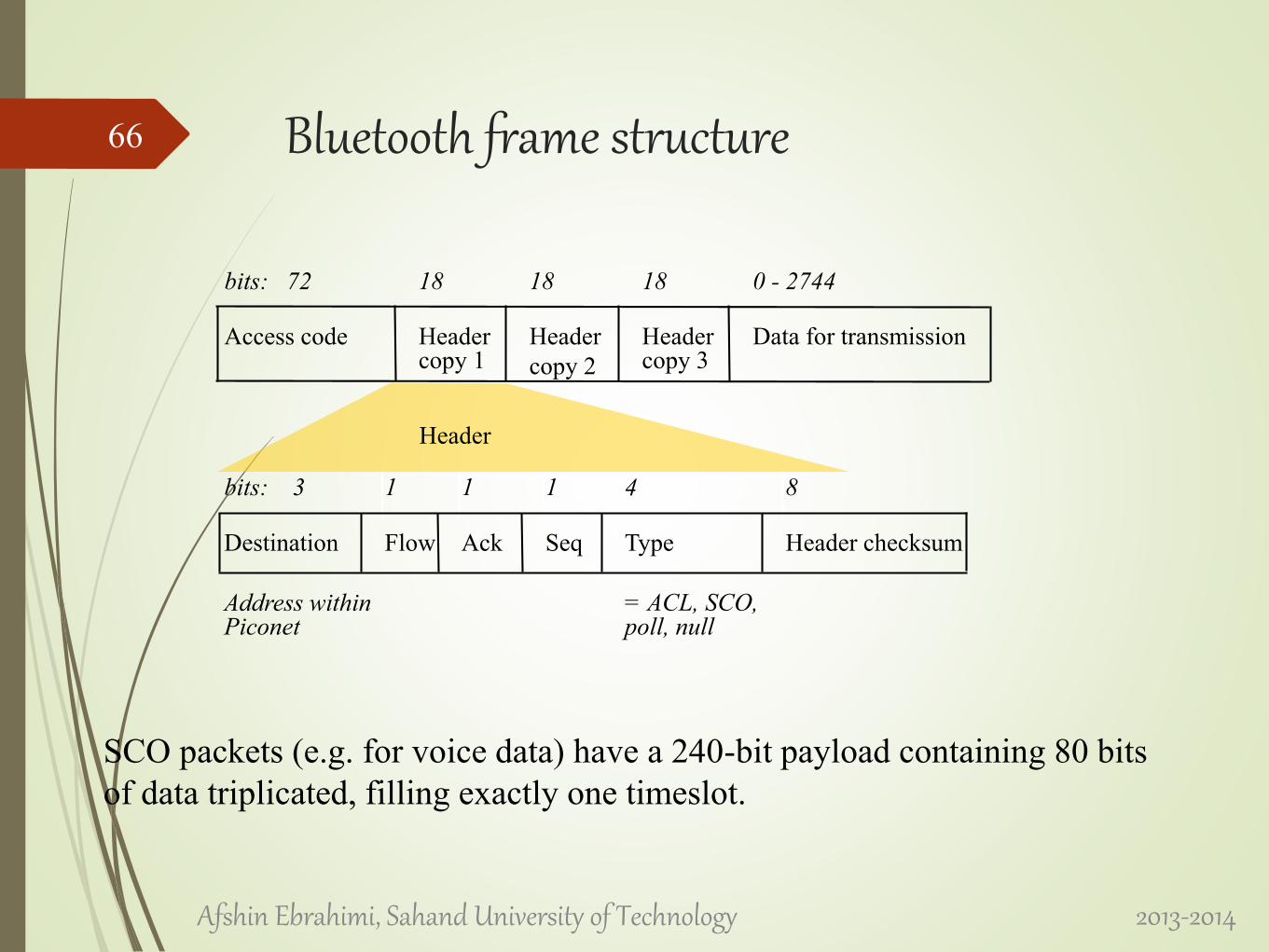
Bluetooth frame structure
SCO packets (e.g. for voice data) have a 240-bit payload containing 80 bits
of data triplicated, filling exactly one timeslot.
bits: 72 18 18 18 0 - 2744
Access code Headercopy 1
Header
copy 2
Headercopy 3
Data for transmission
bits: 3 1 1 1 4 8
Destination Flow Ack Seq Type Header checksum
Address withinPiconet
= ACL, SCO,poll, null
Header
2013-2014Afshin Ebrahimi, Sahand University of Technology
66