distributed modbus tcp logic controller m251 - system user...
TRANSCRIPT

Distributed Modbus TCP Logic Controller M251
EIO0000001680 11/2015
EIO
0000
0016
80.0
2
www.schneider-electric.com
Distributed Modbus TCP Logic Controller M251System User Guide
11/2015

The information provided in this documentation contains general descriptions and/or technical characteristics of the performance of the products contained herein. This documentation is not intended as a substitute for and is not to be used for determining suitability or reliability of these products for specific user applications. It is the duty of any such user or integrator to perform the appropriate and complete risk analysis, evaluation and testing of the products with respect to the relevant specific application or use thereof. Neither Schneider Electric nor any of its affiliates or subsidiaries shall be responsible or liable for misuse of the information contained herein. If you have any suggestions for improvements or amendments or have found errors in this publication, please notify us.
No part of this document may be reproduced in any form or by any means, electronic or mechanical, including photocopying, without express written permission of Schneider Electric.
All pertinent state, regional, and local safety regulations must be observed when installing and using this product. For reasons of safety and to help ensure compliance with documented system data, only the manufacturer should perform repairs to components.
When devices are used for applications with technical safety requirements, the relevant instructions must be followed.
Failure to use Schneider Electric software or approved software with our hardware products may result in injury, harm, or improper operating results.
Failure to observe this information can result in injury or equipment damage.
© 2015 Schneider Electric. All rights reserved.
2 EIO0000001680 11/2015

Table of Contents
Safety Information . . . . . . . . . . . . . . . . . . . . . . . . . . . . . 7About the Book. . . . . . . . . . . . . . . . . . . . . . . . . . . . . . . . 11
Chapter 1 General Information . . . . . . . . . . . . . . . . . . . . . . . . . . . . 17Introduction . . . . . . . . . . . . . . . . . . . . . . . . . . . . . . . . . . . . . . . . . . . . . 18Deliverables. . . . . . . . . . . . . . . . . . . . . . . . . . . . . . . . . . . . . . . . . . . . . 19
Chapter 2 System Architecture. . . . . . . . . . . . . . . . . . . . . . . . . . . . 21Architecture Related Safety Information . . . . . . . . . . . . . . . . . . . . . . . 22System Architecture . . . . . . . . . . . . . . . . . . . . . . . . . . . . . . . . . . . . . . 24
Chapter 3 Safety & Safety Requirements . . . . . . . . . . . . . . . . . . . 29Safety Evolution Structure for the System User Guides . . . . . . . . . . . 30Evolution of Legal Framework . . . . . . . . . . . . . . . . . . . . . . . . . . . . . . . 31Risk Assessment . . . . . . . . . . . . . . . . . . . . . . . . . . . . . . . . . . . . . . . . . 34Functional Safety Standards . . . . . . . . . . . . . . . . . . . . . . . . . . . . . . . . 38Standard EN ISO 13849-1 Machinery Safety - Safety-Related Parts of Control System . . . . . . . . . . . . . . . . . . . . . . . . . . . . . . . . . . . . . . . . . . 39Standard EN/IEC 62061 Machinery Safety - Safety-Related Parts of Control System . . . . . . . . . . . . . . . . . . . . . . . . . . . . . . . . . . . . . . . . . . 47Selecting the Applicable Standard. . . . . . . . . . . . . . . . . . . . . . . . . . . . 54More Information Regarding Safety. . . . . . . . . . . . . . . . . . . . . . . . . . . 55Functional Safety Measures Implemented in this Architecture . . . . . . 58
Chapter 4 Hardware . . . . . . . . . . . . . . . . . . . . . . . . . . . . . . . . . . . . . 614.1 Electrical Distribution and Monitoring . . . . . . . . . . . . . . . . . . . . . . . . . 62
PowerPact H-Frame Circuit Breaker - Hardware . . . . . . . . . . . . . . . . 63Multi 9 System C60 Multi-Standard Range - Hardware. . . . . . . . . . . . 65Phaseo Power Supply Universal - Hardware . . . . . . . . . . . . . . . . . . . 66iEM31xx Energy Meter Series - Hardware . . . . . . . . . . . . . . . . . . . . . 68
4.2 Safety Modules . . . . . . . . . . . . . . . . . . . . . . . . . . . . . . . . . . . . . . . . . . 72Preventa XPSAF Safety Module - Hardware. . . . . . . . . . . . . . . . . . . . 73Modicon TM3 Safety Module - Hardware . . . . . . . . . . . . . . . . . . . . . . 75Preventa Detection and Dialog - Hardware . . . . . . . . . . . . . . . . . . . . . 78
4.3 HMI . . . . . . . . . . . . . . . . . . . . . . . . . . . . . . . . . . . . . . . . . . . . . . . . . . . 79Magelis HMI GTO - Hardware . . . . . . . . . . . . . . . . . . . . . . . . . . . . . . . 80Harmony ZBRN1/ZBRN2 Access Point - Hardware . . . . . . . . . . . . . . 82Harmony Control and Signaling - Hardware . . . . . . . . . . . . . . . . . . . . 85
EIO0000001680 11/2015 3
4.4 Controller . . . . . . . . . . . . . . . . . . . . . . . . . . . . . . . . . . . . . . . . . . . . . . . 86Modicon M251 Logic Controller - Hardware. . . . . . . . . . . . . . . . . . . . . 87Modicon TM3 Modules - Hardware . . . . . . . . . . . . . . . . . . . . . . . . . . . 91TM3XTYS4 TeSys Module - Hardware . . . . . . . . . . . . . . . . . . . . . . . . 93Modicon OTB - Hardware . . . . . . . . . . . . . . . . . . . . . . . . . . . . . . . . . . 99Modicon TM2 Modules - Hardware . . . . . . . . . . . . . . . . . . . . . . . . . . . 102Advantys ETB I/O Module - Hardware . . . . . . . . . . . . . . . . . . . . . . . . . 105
4.5 Communication . . . . . . . . . . . . . . . . . . . . . . . . . . . . . . . . . . . . . . . . . . 110ConneXium Ethernet Switch (Managed) - Hardware . . . . . . . . . . . . . . 111ConneXium Ethernet Switch (Unmanaged) - Hardware . . . . . . . . . . . 115ConneXium Ethernet Switch (Unmanaged) IP 67 - Hardware . . . . . . . 117
4.6 Motor Control . . . . . . . . . . . . . . . . . . . . . . . . . . . . . . . . . . . . . . . . . . . . 120TeSys D Contactor - Hardware . . . . . . . . . . . . . . . . . . . . . . . . . . . . . . 121TeSys GV2 Motor Circuit Breakers - Hardware . . . . . . . . . . . . . . . . . . 123TeSys U LU2B Motor Starter- Hardware . . . . . . . . . . . . . . . . . . . . . . . 125TeSys GV2DP - Hardware . . . . . . . . . . . . . . . . . . . . . . . . . . . . . . . . . . 129TeSys LAD5Cxx Wiring Adapter - Hardware . . . . . . . . . . . . . . . . . . . . 131Altistart 01 Soft Starter - Hardware . . . . . . . . . . . . . . . . . . . . . . . . . . . 133Altivar 12 Variable Speed Drive - Hardware . . . . . . . . . . . . . . . . . . . . 136Altivar 32 Variable Speed Drive - Hardware . . . . . . . . . . . . . . . . . . . . 140Lexium 32M Servo Drive - Hardware . . . . . . . . . . . . . . . . . . . . . . . . . . 144Lexium BSH/BMH Servo Motors - Hardware . . . . . . . . . . . . . . . . . . . . 149
4.7 Detection . . . . . . . . . . . . . . . . . . . . . . . . . . . . . . . . . . . . . . . . . . . . . . . 151OsiSense XGCS850 RFID - Hardware . . . . . . . . . . . . . . . . . . . . . . . . 152OsiSense Industrial Sensors - Hardware . . . . . . . . . . . . . . . . . . . . . . . 155
Chapter 5 Communication Topology and Wiring Guide . . . . . . . 1575.1 Introduction to System Communication . . . . . . . . . . . . . . . . . . . . . . . . 158
Introduction . . . . . . . . . . . . . . . . . . . . . . . . . . . . . . . . . . . . . . . . . . . . . 1585.2 Ethernet Network . . . . . . . . . . . . . . . . . . . . . . . . . . . . . . . . . . . . . . . . . 159
Network Planning and Installation . . . . . . . . . . . . . . . . . . . . . . . . . . . . 160Ethernet Network Topology . . . . . . . . . . . . . . . . . . . . . . . . . . . . . . . . . 163Ethernet Wiring . . . . . . . . . . . . . . . . . . . . . . . . . . . . . . . . . . . . . . . . . . 164Modicon M251 Logic Controller - Ethernet Wiring . . . . . . . . . . . . . . . . 167Altivar 32 Variable Speed Drive - Ethernet Wiring . . . . . . . . . . . . . . . . 169Lexium 32M Servo Drive - Ethernet Wiring . . . . . . . . . . . . . . . . . . . . . 171Magelis HMI GTO5310 - Ethernet Wiring . . . . . . . . . . . . . . . . . . . . . . 173OsiSense XGCS850 RFID - Ethernet Wiring . . . . . . . . . . . . . . . . . . . . 174
4 EIO0000001680 11/2015

Advantys ETB - Ethernet Wiring . . . . . . . . . . . . . . . . . . . . . . . . . . . . . 175Modicon OTB - Ethernet Wiring. . . . . . . . . . . . . . . . . . . . . . . . . . . . . . 177Absolute Encoder - Ethernet Wiring . . . . . . . . . . . . . . . . . . . . . . . . . . 180Harmony ZBRN1 Access Point - Ethernet Wiring . . . . . . . . . . . . . . . . 182
5.3 Modbus Serial Line Network . . . . . . . . . . . . . . . . . . . . . . . . . . . . . . . . 183Modbus SL Network Topology . . . . . . . . . . . . . . . . . . . . . . . . . . . . . . 184Modbus SL Wiring . . . . . . . . . . . . . . . . . . . . . . . . . . . . . . . . . . . . . . . . 185Modicon M251 Logic Controller - Modbus SL Wiring . . . . . . . . . . . . . 186iEM31xx Energy Meter - Modbus SL Wiring . . . . . . . . . . . . . . . . . . . . 188
Chapter 6 Implementation . . . . . . . . . . . . . . . . . . . . . . . . . . . . . . . . 1916.1 Software Requirements . . . . . . . . . . . . . . . . . . . . . . . . . . . . . . . . . . . . 192
Software Requirements . . . . . . . . . . . . . . . . . . . . . . . . . . . . . . . . . . . . 1926.2 Access the SoMachine Project Template . . . . . . . . . . . . . . . . . . . . . . 193
Access the SoMachine Project Template . . . . . . . . . . . . . . . . . . . . . . 1936.3 Project . . . . . . . . . . . . . . . . . . . . . . . . . . . . . . . . . . . . . . . . . . . . . . . . . 194
Controller . . . . . . . . . . . . . . . . . . . . . . . . . . . . . . . . . . . . . . . . . . . . . . . 195HMI . . . . . . . . . . . . . . . . . . . . . . . . . . . . . . . . . . . . . . . . . . . . . . . . . . . 198Devices . . . . . . . . . . . . . . . . . . . . . . . . . . . . . . . . . . . . . . . . . . . . . . . . 200Application . . . . . . . . . . . . . . . . . . . . . . . . . . . . . . . . . . . . . . . . . . . . . . 209Vijeo-Designer . . . . . . . . . . . . . . . . . . . . . . . . . . . . . . . . . . . . . . . . . . . 211
Chapter 7 System Setup . . . . . . . . . . . . . . . . . . . . . . . . . . . . . . . . . 2137.1 Setup Controller and HMI . . . . . . . . . . . . . . . . . . . . . . . . . . . . . . . . . . 215
Setup Controller and HMI . . . . . . . . . . . . . . . . . . . . . . . . . . . . . . . . . . 2157.2 Setup Other Devices . . . . . . . . . . . . . . . . . . . . . . . . . . . . . . . . . . . . . . 218
Network and Device Parameter Settings. . . . . . . . . . . . . . . . . . . . . . . 219TeSys U Motor Starter - Setup . . . . . . . . . . . . . . . . . . . . . . . . . . . . . . 220Altistart 01 Soft Starter - Setup . . . . . . . . . . . . . . . . . . . . . . . . . . . . . . 221Altivar 12 Variable Speed Drive - Setup . . . . . . . . . . . . . . . . . . . . . . . 223Altivar 32 Variable Speed Drive - Modbus TCP Setup . . . . . . . . . . . . 226Lexium 32M Servo Drive - Modbus TCP Setup. . . . . . . . . . . . . . . . . . 230iEM3150 Energy Meter - Modbus SL Setup . . . . . . . . . . . . . . . . . . . . 233Harmony ZBRN1 Access Point - Modbus TCP Setup. . . . . . . . . . . . . 235Advantys ETB - Modbus TCP Setup . . . . . . . . . . . . . . . . . . . . . . . . . . 237ConneXium TCSESM Ethernet Switch - Setup . . . . . . . . . . . . . . . . . . 241Absolute Encoder - Modbus TCP Setup . . . . . . . . . . . . . . . . . . . . . . . 245OsiSense XGCS850 RFID - Ethernet Setup . . . . . . . . . . . . . . . . . . . . 246
EIO0000001680 11/2015 5

Chapter 8 Adapt TVDA Template . . . . . . . . . . . . . . . . . . . . . . . . . . 2518.1 Adapt SoMachine Project Template. . . . . . . . . . . . . . . . . . . . . . . . . . . 252
Introduction . . . . . . . . . . . . . . . . . . . . . . . . . . . . . . . . . . . . . . . . . . . . . 253Device Modules in General . . . . . . . . . . . . . . . . . . . . . . . . . . . . . . . . . 254Device Modules Used in This Project Template . . . . . . . . . . . . . . . . . 255Add Device Modules . . . . . . . . . . . . . . . . . . . . . . . . . . . . . . . . . . . . . . 256Remove Device Module . . . . . . . . . . . . . . . . . . . . . . . . . . . . . . . . . . . . 258
8.2 Adapt HMI Application . . . . . . . . . . . . . . . . . . . . . . . . . . . . . . . . . . . . . 259Introduction . . . . . . . . . . . . . . . . . . . . . . . . . . . . . . . . . . . . . . . . . . . . . 259
Chapter 9 Bill of Material (BOM). . . . . . . . . . . . . . . . . . . . . . . . . . . 261Bill of Material (BOM) . . . . . . . . . . . . . . . . . . . . . . . . . . . . . . . . . . . . . . 261
Glossary . . . . . . . . . . . . . . . . . . . . . . . . . . . . . . . . . . . . . . . . . 271Index . . . . . . . . . . . . . . . . . . . . . . . . . . . . . . . . . . . . . . . . . 277
6 EIO0000001680 11/2015

Safety Information
Important Information
NOTICE
Read these instructions carefully, and look at the equipment to become familiar with the device before trying to install, operate, or maintain it. The following special messages may appear throughout this documentation or on the equipment to warn of potential hazards or to call attention to information that clarifies or simplifies a procedure.
EIO0000001680 11/2015 7

PLEASE NOTE
Electrical equipment should be installed, operated, serviced, and maintained only by qualified personnel. No responsibility is assumed by Schneider Electric for any consequences arising out of the use of this material.
A qualified person is one who has skills and knowledge related to the construction and operation of electrical equipment and its installation, and has received safety training to recognize and avoid the hazards involved.
BEFORE YOU BEGIN
Do not use this product on machinery lacking effective point-of-operation guarding. Lack of effective point-of-operation guarding on a machine can result in serious injury to the operator of that machine.
This automation equipment and related software is used to control a variety of industrial processes. The type or model of automation equipment suitable for each application will vary depending on factors such as the control function required, degree of protection required, production methods, unusual conditions, government regulations, etc. In some applications, more than one processor may be required, as when backup redundancy is needed.
Only you, the user, machine builder or system integrator can be aware of all the conditions and factors present during setup, operation, and maintenance of the machine and, therefore, can determine the automation equipment and the related safeties and interlocks which can be properly used. When selecting automation and control equipment and related software for a particular application, you should refer to the applicable local and national standards and regulations. The National Safety Council's Accident Prevention Manual (nationally recognized in the United States of America) also provides much useful information.
In some applications, such as packaging machinery, additional operator protection such as point-of-operation guarding must be provided. This is necessary if the operator's hands and other parts of the body are free to enter the pinch points or other hazardous areas and serious injury can occur. Software products alone cannot protect an operator from injury. For this reason the software cannot be substituted for or take the place of point-of-operation protection.
WARNINGUNGUARDED EQUIPMENT
Do not use this software and related automation equipment on equipment which does not have point-of-operation protection.
Do not reach into machinery during operation.
Failure to follow these instructions can result in death, serious injury, or equipment damage.
8 EIO0000001680 11/2015

Ensure that appropriate safeties and mechanical/electrical interlocks related to point-of-operation protection have been installed and are operational before placing the equipment into service. All interlocks and safeties related to point-of-operation protection must be coordinated with the related automation equipment and software programming.
NOTE: Coordination of safeties and mechanical/electrical interlocks for point-of-operation protection is outside the scope of the Function Block Library, System User Guide, or other implementation referenced in this documentation.
START-UP AND TEST
Before using electrical control and automation equipment for regular operation after installation, the system should be given a start-up test by qualified personnel to verify correct operation of the equipment. It is important that arrangements for such a check be made and that enough time is allowed to perform complete and satisfactory testing.
Follow all start-up tests recommended in the equipment documentation. Store all equipment documentation for future references.
Software testing must be done in both simulated and real environments.
Verify that the completed system is free from all short circuits and temporary grounds that are not installed according to local regulations (according to the National Electrical Code in the U.S.A, for instance). If high-potential voltage testing is necessary, follow recommendations in equipment documentation to prevent accidental equipment damage.
Before energizing equipment: Remove tools, meters, and debris from equipment. Close the equipment enclosure door. Remove all temporary grounds from incoming power lines. Perform all start-up tests recommended by the manufacturer.
CAUTIONEQUIPMENT OPERATION HAZARD
Verify that all installation and set up procedures have been completed. Before operational tests are performed, remove all blocks or other temporary holding means
used for shipment from all component devices. Remove tools, meters, and debris from equipment.
Failure to follow these instructions can result in injury or equipment damage.
EIO0000001680 11/2015 9

OPERATION AND ADJUSTMENTS
The following precautions are from the NEMA Standards Publication ICS 7.1-1995 (English version prevails): Regardless of the care exercised in the design and manufacture of equipment or in the selection
and ratings of components, there are hazards that can be encountered if such equipment is improperly operated.
It is sometimes possible to misadjust the equipment and thus produce unsatisfactory or unsafe operation. Always use the manufacturer’s instructions as a guide for functional adjustments. Personnel who have access to these adjustments should be familiar with the equipment manufacturer’s instructions and the machinery used with the electrical equipment.
Only those operational adjustments actually required by the operator should be accessible to the operator. Access to other controls should be restricted to prevent unauthorized changes in operating characteristics.
10 EIO0000001680 11/2015

About the Book
At a Glance
Document Scope
This document describes a generic architecture based on Modicon M251 Logic Controller.
This document is intended to provide a quick introduction to the described system.
It is not intended to replace any specific product documentation, nor any of your own design documentation. On the contrary, it offers additional information to the product documentation for installing, configuring, and implementing the system.
The architecture described in this document is not a specific product in the normal commercial sense. It describes an example of how Schneider Electric and third-party components may be integrated to fulfill an industrial application.
A detailed functional description or the specification for a specific user application is not part of this document. Nevertheless, the document outlines some typical applications where the system could be implemented.
Your specific application requirements may be different and will require additional and/or different components. In this case, you will have to adapt the information provided in this document to your particular needs. To do so, you will need to consult the specific product documentation of the components that you are substituting in this architecture.
Pay particular attention in conforming to any safety information, different electrical requirements, and normative standards that would apply to your adaptation.
There are some major components in the architecture described in this document that cannot be substituted without completely invalidating the architecture, descriptions, instructions, wiring diagrams, and compatibility between the various software and hardware components specified herein.
Be aware of the consequences of component substitution in the architecture described in this document as substitutions may impair the compatibility and interoperability of software and hardware.
Validity Note
This document has been updated for the release of SoMachine V4.1 SP2.
EIO0000001680 11/2015 11

Related Documents
Title of Documentation Reference Number
PowerPact Multistandard, Catalogue LVPED212023EN
The essential guide for power supplies and transformers DIA3ED2070412EN
C60 Multi-Standard Range, Catalog CM909003E
Phaseo power supplies and transformers, Catalogue Pages 14082-EN
iEM3100 series / iEM3200 series, Energy Meters, User Manual DOCA0005EN
Control and protection components MKTED210011EN
Control and signaling components MKTED208031EN
LAD5C Instruction Sheet HRB8873800
Preventa solutions for efficient machine safety - catalogue MKTED2140201EN
Magelis GTO, User Manual EIO0000001133 (ENG)
Magelis XBT GC/XBT GK/XBTGT, SoMachine - Combo and Network Drivers
EIO00000000219 (ENG)
Harmony XB5R, ZBRN1/ZBRN2, User Manual EIO0000001177 (EN)
Harmony XB5R, Expert Instruction Sheet EIO0000000812 (EN)
Modicon M251 Logic Controller, Hardware Guide EIO0000001486
Modicon M251 Logic Controller, Programming Guide EIO0000001462
Modicon TM3, Digital I/O Modules, Hardware Guide EIO0000001408
Modicon TM2, Analog I/O Modules, Hardware Guide EIO0000000034
Modicon TM2, Digital I/O Modules, Hardware Guide EIO0000000028
Modicon TM2, High Speed Counter Modules, Hardware Guide EIO0000000022
Modicon TM3, Expert I/O Modules, Hardware Guide EIO0000001420
Modicon TM3, Expansion Modules Configuration, Programming Guide
EIO0000001402
Advantys ETB, IP67 Ethernet Block I/O Modules for Modbus TCP/IP, User Guide
EIO0000000158
Advantys OTB Ethernet, Remote Inputs/Outputs, User Manual 1606385
ConneXium Ethernet Cabling System TCSESM, TCSESM-E Managed Switch Basic Configuration, User Manual
31007122
ConneXium TCSESM, TCSESM-E Managed Switch Redundancy Configuration, User Manual
31007126
ConneXium TCSESM, TCSESM-E, Managed Switch, Web-based Interface, Reference Manual
EIO0000000482
ConneXium TCSESM Managed Switch, Installation Manual 31007118
12 EIO0000001680 11/2015

You can download these technical publications and other technical information from our website at http://download.schneider-electric.com
ConneXium Industrial Ethernet Cabling System, 5TX IP67 Switch, TCSESU051F0
31006691
ConneXium Ethernet Switches, TCSESU0••F•N0, Quick Reference Guide
31007950
Advantys ETB, IP67 Ethernet Block I/O Modules for Modbus TCP/IP, User Guide
EIO0000000158
TeSys U, Starter-controllers, Catalogue DIA1ED2081003EN
The essential guide, TeSys for power control & protection DIA1ED2040401EN
ATV32 - Safety integrated functions manual S1A45606
Altivar 32, Variable speed drives for synchronous and asynchronous motors, Installation manual
S1A28686 (ENG)
Altivar 32, Variable speed drives for synchronous and asynchronous motors, Programming manual
S1A28692 (ENG)
Altivar 32 Variable speed drives for synchronous and asynchronous motors, Modbus TCP - EtherNet/IP, Communication Manual
S1A28701
Altistart 01, Soft Starts for Single-Phase and Three-Phase Asynchronous Motors
45A01SS
Characteristics, Soft starters for asynchronous motors Altistart 01 60541-EN
Reduce mechanical stress on your machines DIA2ED1121204EN
Instruction Sheet ATS01N1...FT 1624685
LXM32M AC servo drive, Product manual 0198441113767
LXM32M, Modbus-TCP module, Fieldbus manual 0198441113843
BMH, Servo motor, Motor manual 0198441113749 (ENG)
BSH, Servo motor, Motor manual 0198441113837 (ENG)
Detection for automation solutions OsiSense MKTED210041EN
RFID OsiSense XG, Ethernet Smart Antenna, User Manual EIO0000001601
The essential guide of Detection DIA4ED2041203EN
Transparent Ready, User Guide 31006929
Modbus Serial Line, Planning and Installation Guide 33003925
SoMachine Programming Guide EIO0000000067 (ENG)
Title of Documentation Reference Number
EIO0000001680 11/2015 13

Product Related Information
This equipment has been designed to operate outside of any hazardous location. Only install this equipment in zones known to be free of a hazardous atmosphere.
DANGERHAZARD OF ELECTRIC SHOCK, EXPLOSION OR ARC FLASH
Disconnect all power from all equipment including connected devices prior to removing any covers or doors, or installing or removing any accessories, hardware, cables, or wires except under the specific conditions specified in the appropriate hardware guide for this equipment.
Always use a properly rated voltage sensing device to confirm the power is off where and when indicated.
Replace and secure all covers, accessories, hardware, cables, and wires and confirm that a proper ground connection exists before applying power to the unit.
Use only the specified voltage when operating this equipment and any associated products.
Failure to follow these instructions will result in death or serious injury.
DANGERPOTENTIAL FOR EXPLOSION
Install and use this equipment in non-hazardous locations only.
Failure to follow these instructions will result in death or serious injury.
WARNINGLOSS OF CONTROL
The designer of any control scheme must consider the potential failure modes of control paths and, for certain critical control functions, provide a means to achieve a safe state during and after a path failure. Examples of critical control functions are emergency stop and overtravel stop, power outage and restart.
Separate or redundant control paths must be provided for critical control functions. System control paths may include communication links. Consideration must be given to the
implications of unanticipated transmission delays or failures of the link.
Observe all accident prevention regulations and local safety guidelines.1
Each implementation of this equipment must be individually and thoroughly tested for proper operation before being placed into service.
Failure to follow these instructions can result in death, serious injury, or equipment damage.
14 EIO0000001680 11/2015

1 For additional information, refer to NEMA ICS 1.1 (latest edition), "Safety Guidelines for the Application, Installation, and Maintenance of Solid State Control" and to NEMA ICS 7.1 (latest edition), "Safety Standards for Construction and Guide for Selection, Installation and Operation of Adjustable-Speed Drive Systems" or their equivalent governing your particular location.
Terminology Derived from Standards
The technical terms, terminology, symbols and the corresponding descriptions in this manual, or that appear in or on the products themselves, are generally derived from the terms or definitions of international standards.
In the area of functional safety systems, drives and general automation, this may include, but is not limited to, terms such as safety, safety function, safe state, fault, fault reset, malfunction, failure, error, error message, dangerous, etc.
Among others, these standards include:
WARNINGUNINTENDED EQUIPMENT OPERATION
Only use software approved by Schneider Electric for use with this equipment. Update your application program every time you change the physical hardware configuration.
Failure to follow these instructions can result in death, serious injury, or equipment damage.
Standard Description
EN 61131-2:2007 Programmable controllers, part 2: Equipment requirements and tests.
ISO 13849-1:2008 Safety of machinery: Safety related parts of control systems.General principles for design.
EN 61496-1:2013 Safety of machinery: Electro-sensitive protective equipment.Part 1: General requirements and tests.
ISO 12100:2010 Safety of machinery - General principles for design - Risk assessment and risk reduction
EN 60204-1:2006 Safety of machinery - Electrical equipment of machines - Part 1: General requirements
EN 1088:2008ISO 14119:2013
Safety of machinery - Interlocking devices associated with guards - Principles for design and selection
ISO 13850:2006 Safety of machinery - Emergency stop - Principles for design
EN/IEC 62061:2005 Safety of machinery - Functional safety of safety-related electrical, electronic, and electronic programmable control systems
IEC 61508-1:2010 Functional safety of electrical/electronic/programmable electronic safety-related systems: General requirements.
EIO0000001680 11/2015 15

In addition, terms used in the present document may tangentially be used as they are derived from other standards such as:
Finally, the term zone of operation may be used in conjunction with the description of specific hazards, and is defined as it is for a hazard zone or danger zone in the EC Machinery Directive (EC/2006/42) and ISO 12100:2010.
NOTE: The aforementioned standards may or may not apply to the specific products cited in the present documentation. For more information concerning the individual standards applicable to the products described herein, see the characteristics tables for those product references.
IEC 61508-2:2010 Functional safety of electrical/electronic/programmable electronic safety-related systems: Requirements for electrical/electronic/programmable electronic safety-related systems.
IEC 61508-3:2010 Functional safety of electrical/electronic/programmable electronic safety-related systems: Software requirements.
IEC 61784-3:2008 Digital data communication for measurement and control: Functional safety field buses.
2006/42/EC Machinery Directive
2004/108/EC Electromagnetic Compatibility Directive
2006/95/EC Low Voltage Directive
Standard Description
IEC 60034 series Rotating electrical machines
IEC 61800 series Adjustable speed electrical power drive systems
IEC 61158 series Digital data communications for measurement and control – Fieldbus for use in industrial control systems
Standard Description
16 EIO0000001680 11/2015
Distributed Modbus TCP Logic Controller M251
General Information
EIO0000001680 11/2015
General Information
Chapter 1General Information
What Is in This Chapter?
This chapter contains the following topics:
Topic Page
Introduction 18
Deliverables 19
EIO0000001680 11/2015 17

General Information
Introduction
Overview
With Tested Validated Documented Architectures (TVDAs), Schneider Electric provides complete controlling system proposals applicable for a wide range of applications.
TVDAs are meant to help you to quickly find cost efficient controlling solutions, optimize the system implementation time, gain a competitive advantage and optimize overall costs for your machine.
With detailed component lists, wiring diagrams, commissioning guides, controller, and HMI applications the effort to assemble and setup the system becomes significantly reduced.
For a high level of reliability and robustness each TVDA is subjected to extensive system validation. Specific performance requirements as well as installation constraints are considered in the system design.
TVDAs provide a high level of openness for adaptations. With a clear separated project template structure and dedicated functions embedded in SoMachine and SoMachine Basic, required modifications can be realized quickly.
WARNINGUNINTENDED EQUIPMENT OPERATION
Thoroughly read and understand any and all device manuals for the characteristics and properties of the devices employed before attempting to modify parameters that may alter those characteristics and properties.
Failure to follow these instructions can result in death, serious injury, or equipment damage.
18 EIO0000001680 11/2015

General Information
Deliverables
SoMachine Project Template
The SoMachine Project Template is comprised of a ready-to-use controller project covering the complete system configuration. Within the project template, you can find preconfigured application code to operate field devices, to monitor the system status, and to handle errors that are detected.
HMI Application
The HMI application is a ready-to-use interface that can: Control the main functionalities of the system Indicate the system status Visualize the system errors that are detected
System User Guide (SUG)
The System User Guide provides: System documentation with a focus on installation, commissioning, and adaptation of the
system Bill of Material (BOM), including power distribution components Detailed installation information for each component Guidance on how to commission the complete system Introduction of available ranges and key features of each component used within the
architecture Guidance on how to adapt the system efficiently by making use of dedicated functions provided
within SoMachine software
Wiring Diagram
The wiring diagrams provide detailed guidance on the system wiring, and are reusable as a base to generate final technical documentation of the controlling system.
The wiring diagrams are provided for download on the Schneider Electric web page www.schneider-electric.com and are available in the following file formats: EPLAN Electric P8 V2.4 project archive *.pdf (generated with EPLAN) *.dwg (generated with EPLAN)
EIO0000001680 11/2015 19

General Information
20 EIO0000001680 11/2015

Distributed Modbus TCP Logic Controller M251
System Architecture
EIO0000001680 11/2015
System Architecture
Chapter 2System Architecture
What Is in This Chapter?
This chapter contains the following topics:
Topic Page
Architecture Related Safety Information 22
System Architecture 24
EIO0000001680 11/2015 21

System Architecture
Architecture Related Safety Information
Remote Devices
Remote control operating devices may lead to unintended equipment operation by: incorrect operation insufficient view on the machine during operation unintentional manipulation
Care must be taken and provisions made for use of this product as a control device to avoid inadvertent consequences of commanded machine operation, controller state changes, or alteration of data memory or machine operating parameters.
Wireless Devices
Data transmission between wireless devices can be influenced by environmental conditions. Especially for portable devices, such as wireless and batteryless push-buttons, the quality of the wireless communication is changing depending on the position of the device to the receiver.
WARNINGUNINTENDED EQUIPMENT OPERATION
Place operator devices of the control system near the machine or in a place where you have full view of the machine.
Protect operator commands against unauthorized access. If remote control is a necessary design aspect of the application, ensure that there is a local,
competent, and qualified observer present when operating from a remote location. Configure and install the Run/Stop input for the application so that local control over the
starting or stopping of the controller can be maintained regardless of the remote commands sent to the controller.
Failure to follow these instructions can result in death, serious injury, or equipment damage.
WARNINGLOSS OF CONTROL
Do not use wireless equipment as the only means of control for critical control functions such as motor start/stop or power disconnect.
Provide separate or redundant control paths for critical control functions. Provide a means to achieve a safe state during and after a path failure for critical control
functions such as emergency stop and overtravel stop. Improve the reliability of the wireless network by the use of repeater(s).
Failure to follow these instructions can result in death, serious injury, or equipment damage.
22 EIO0000001680 11/2015

System Architecture
Communication
Fieldbusses or network communication may lead to loss of control by: Communication disturbance by external influences (for example wiring or EMC) Delay during communication Interruption of communication Inaccurate communication
1 For additional information, refer to NEMA ICS 1.1 (latest edition), "Safety Guidelines for the Application, Installation, and Maintenance of Solid State Control" and to NEMA ICS 7.1 (latest edition), "Safety Standards for Construction and Guide for Selection, Installation and Operation of Adjustable-Speed Drive Systems" or their equivalent governing your particular location.
WARNINGLOSS OF CONTROL
The designer of any control scheme must consider the potential failure modes of control paths and, for certain critical control functions, provide a means to achieve a safe state during and after a path failure. Examples of critical control functions are emergency stop and overtravel stop, power outage and restart.
Separate or redundant control paths must be provided for critical control functions. System control paths may include communication links. Consideration must be given to the
implications of unanticipated transmission delays or failures of the link.
Observe all accident prevention regulations and local safety guidelines.1
Each implementation of this equipment must be individually and thoroughly tested for proper operation before being placed into service.
Failure to follow these instructions can result in death, serious injury, or equipment damage.
EIO0000001680 11/2015 23

System Architecture
System Architecture
Overview
The architecture is arranged into the optimized performance class and is distinguished by the following characteristics: Modicon M251 Logic Controller 2 optimized Magelis touch panels HMIGTO4310 and HMIGTO5315 Energy metering Industrial Ethernet (Modbus TCP) Modbus serial line communication Ethernet connectivity Application of machine safety Wireless and batteryless operator push-buttons 82 digital inputs (16 local and 66 distributed) 56 digital outputs (16 local and 40 distributed)
The following devices are linked to the Industrial Ethernet (Modbus TCP) and are controlled and monitored by the controller as Modbus TCP slave: 2 Altivar 32 variable speed drives 2 Lexium 32M servo drives 1 Harmony wireless push-button access point 1 Absolute multiturn encoder 3 OsiSense XG RFID smart antennas 1 Modicon ETB IP 67 distributed I/O block 1 Modicon OTB equipped with TM2 expansion modules
24 EIO0000001680 11/2015

System Architecture
Layout
Main cabinet
* Conformance to UL standards requires that fuses are used for the branch circuit protection in place of the motor circuit breakers depicted above in front of the Lexium servo drives. For more information, refer to LXM32M AC servo drive, Product manual, 0198441113767.
1 PowerPact circuit breaker 13 Harmony signaling/control devices
2 iEM3150 energy meter 14 Harmony wireless push-buttons
3 TeSys D LC1D contactor 15 TeSys GV2P motor circuit-breaker
4 Multi-9 C60 (UL 489) circuit breaker 16 Altivar 32 variable speed drive + Ethernet communication module
5 Multi-9 C60 (UL 1077) circuit breaker 17 Lexium 32M servo drive + Ethernet communication module
6 Phaseo power supply 18 Lexium BSH servo motor
7 Modicon M251 Logic Controller 19 Ethernet switch IP 67 (unmanaged)
8 Modicon TM3 embedded safety module 20 OsiSense XG RFID smart antenna (Modbus TCP)
EIO0000001680 11/2015 25

System Architecture
Remote cabinet
9 TM3 digital I/O expansion module 21 Advantys ETB 16 I/O module (Modbus TCP)
10 Magelis HMIGTO touch panel 22 Absolute multiturn encoder (Modbus TCP)
11 ConneXium Ethernet switch (managed) 23 OsiSense sensors and switches
12 Harmony wireless receiver (Modbus TCP) - -
1 ConneXium Ethernet switch (unmanaged) 11 Magelis HMIGTO touch panel (stainless steel)
2 Vario disconnector switch 12 Harmony signaling/control devices
3 TeSys D LC1D contactor 13 TeSys D motor starter and wiring adapter
4 Multi-9 C60 (UL 489) circuit breaker 14 TeSys D motor starter (reversible) and wiring adapter
5 Multi-9 C60 (UL 1077) circuit breaker 15 Altistart ATS01N1 soft starter
6 Phaseo power supply 16 TeSys U motor starter controller
26 EIO0000001680 11/2015

System Architecture
7 Modicon OTB I/O module (Modbus TCP) 17 TeSys U motor starter controller (reversible)
8 TM2 digital I/O expansion module 18 TeSys GV2P motor circuit-breaker
9 Preventa safety module XPSAF 19 Altivar 12 variable speed drive
10 TeSys splitter box, parallel wiring 20 OsiSense sensors + switches
EIO0000001680 11/2015 27

System Architecture
28 EIO0000001680 11/2015

Distributed Modbus TCP Logic Controller M251
Safety & Safety Requirements
EIO0000001680 11/2015
Safety & Safety Requirements
Chapter 3Safety & Safety Requirements
What Is in This Chapter?
This chapter contains the following topics:
Topic Page
Safety Evolution Structure for the System User Guides 30
Evolution of Legal Framework 31
Risk Assessment 34
Functional Safety Standards 38
Standard EN ISO 13849-1 Machinery Safety - Safety-Related Parts of Control System 39
Standard EN/IEC 62061 Machinery Safety - Safety-Related Parts of Control System 47
Selecting the Applicable Standard 54
More Information Regarding Safety 55
Functional Safety Measures Implemented in this Architecture 58
EIO0000001680 11/2015 29

Safety & Safety Requirements
Safety Evolution Structure for the System User Guides
Overview
1. Evolution of legal framework (see page 31)2. Risk assessment (see page 34)3. Functional safety standards overview (see page 38)4. Standard EN ISO 13849-1 machinery safety (see page 39)5. Standard EN/IEC 62061 machinery safety (see page 47)6. Selecting the applicable standard (see page 54)7. Where to get more information regarding safety (see page 55)
a. Safety guideb. Sistemac. Sistema library
8. Concept used on specific TVDA
30 EIO0000001680 11/2015

Safety & Safety Requirements
Evolution of Legal Framework
EC Directive
Legal instrument to harmonize the legislation of the European member states Defines the essential health and safety requirements (EHSRs). Transposed into national law (act, decree, order, regulations).
Standard
A standard is a technical specification approved by a recognized standardization body for repeated or continuous application, with which compliance is not compulsory.
Harmonized Standard
A standard becomes harmonized when published throughout the member states.
Presumption of Conformity
When a product conforms to a harmonized European standard, the reference to which has been published in the official journal of the European Union for a specific directive, and which covers one or more of the essential safety requirements, the product is presumed to comply with those essential safety requirements of the directive.
In many cases European standards (ENs) are technically similar to international (IEC or ISO) standards. However only European standards include a list of which EHSRs are covered, so only European standards can confer a presumption of conformity.
European Directives and Safety Standards
Link between some of the main safety standards and the European directives according with the sectors of activity.
A list of such standards can be accessed at:
http://www.newapproach.org/Directives/DirectiveList.asp
EIO0000001680 11/2015 31

Safety & Safety Requirements
A, B and C Standards
When a type C standard deviates from one or more provisions dealt with by a type A standard or by a type B standard, the type C standard takes precedence. EN ISO 12100 is type A standards.
European standards for the machinery safety form the following structure:
Some examples of these types of standards are:
Manufacturers' Responsibilities
Manufacturers placing machines on the market within the European Economic Area (EEA) must comply with the requirements of the machinery directive. Note that "placing on the market" includes an organization supplying a machine to itself, that is, building or modifying machines for its own use, or importing machines into the EEA.
Type A standardsBasic safety standards giving basic concepts, principles for design, and general aspects that can be applied to all machinery.
Type B standardsGeneric safety standards dealing with one safety aspect or one type of safeguard that can be used across a wide range of machinery: Type B1 standards on particular safety aspects (for example, safety
distances, surface temperature, noise) Type B2 standards on safeguards (for example, two-hand controls,
interlocking devices, pressure sensitive devices, guards)
Type C standardsMachine safety standards dealing with detailed safety requirements for a particular machine or group of machines.
Name Type Description
EN ISO 12100 A 2010 Safety of machinery - General principles for design - Risk assessment and risk reduction
EN ISO 13850 B Emergency stop - Principles for design
EN/IEC 62061 B Functional safety of safety-related electrical, electronic, and electronic programmable control systems
EN ISO 13849-1 B Safety of machinery - safety-related parts of control systems - Part 1 general principles for design
EN 349 B Minimum gaps to avoid crushing of parts of the human body
EN ISO 13857 B Safety of machinery - safety distances to prevent hazard zones being reached by upper and lower limbs
EN 60204-1 B Safety of machinery - Electrical equipment of machines - Part 1: General requirements
EN 1088/ISO 14119 B Interlocking devices associated with guards - Principles for design and selection
32 EIO0000001680 11/2015

Safety & Safety Requirements
Users' Responsibilities
Users of machines need to ensure that newly purchased machines are CE marked, and accompanied by a declaration of conformity to the machinery directive. Machines must be used in accordance with the manufacturer's instructions.
Existing machines taken into service before the machinery directive came into force do not need to comply, although they need to comply with the regulations resulting from the use of work equipment directive and be safe and fit for purpose.
Modification of machines can be considered as manufacture of a new machine, even if for use in-house, and the company modifying a machine needs to be aware that it might need to issue a declaration of conformity and CE marking.
EIO0000001680 11/2015 33

Safety & Safety Requirements
Risk Assessment
European Legislation
Machines are sources of potential risk and the machinery directive requires a risk assessment to ensure that any potential risk is reduced to less than the acceptable risk.
Standard EN/ISO 12100 defines risk as follows: risk is the severity multiplied by the possibility of occurrence. It defines an iterative process for achieving machine safety, which states that the risks for each potential hazard can be determined in 4 stages.
1. Risk assessment2. Determination of machine limits3. Identification of the potential hazard4. Risk evaluation
This method provides the basis for the requisite risk reduction.
Risk Assessment
Risk assessment consists of a series of logic steps which make it possible to analyze and evaluate machinery-related risks systematically.
Risk assessment is followed, whenever necessary, by a reduction of the risk.
This definition taken from standard EN/ISO 12100 is based on an iterative process represented in the diagram opposite.
Definition of risk
34 EIO0000001680 11/2015
Safety & Safety Requirements
Determination of Machine Limits
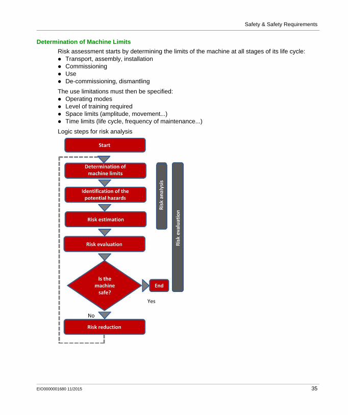
Risk assessment starts by determining the limits of the machine at all stages of its life cycle: Transport, assembly, installation Commissioning Use De-commissioning, dismantling
The use limitations must then be specified: Operating modes Level of training required Space limits (amplitude, movement...) Time limits (life cycle, frequency of maintenance...)
Logic steps for risk analysis
EIO0000001680 11/2015 35

Safety & Safety Requirements
Identification of the Potential Hazard
If a potential hazard exists, a hazardous phenomenon will cause harm if measures are not taken. All the tasks associated with the life cycle of a machine must be identified, such as: Assembly, transport, and installation Adjustment, testing Learning, programming Tool changing Feeding, removal of product from the machine Starting, stopping Emergency stops, restarting after an unexpected stop Maintenance, cleaning, and so on.
The risk is a function of the severity of the harm and the probability that this harm will occur. The severity of the harm takes into account: The severity of injuries (slight, serious, death) The extent of the harm (number of persons)
The probability of the harm occurring takes into account: Exposure to the hazard (nature of access, time spent in the hazardous zone, number of persons
exposed, frequency of access) The occurrence of a hazardous event (accident history, comparison of risks, ...) The possibility of avoiding or limiting the harm (experience, awareness of the risk, ...)
Elements of the risk
Risk Evaluation
Based on the risk assessment, the designer has to define the safety-related control system. To achieve that, the designer will choose one of the 2 standards appropriate to the application: either standard EN ISO 13849-1, which defines performance levels (PL) or standard EN/IEC 62061, which defines safety integrity level (SIL)
36 EIO0000001680 11/2015

Safety & Safety Requirements
Risk Reduction
The process of risk reduction for dangerous events starts by: intrinsic prevention (inherently safe design) definition of the appropriate protective means (guards, carters, fix fences, ...) personnel training
If the selected preventive measure depends on a safety-related control system, the designer has to perform an iterative process for the design of the safety relative control system. The first stage is to define the necessary safety-related control functions: either through the choice of components or by adapting the control system architecture. Redundancy (double circuit components), for
example, significantly increases the reliability of the solution
Once the limits of available technologies have been reached; it will not be possible to further reduce the rate of dangerous failures. To achieve the required level of safety, it will be necessary to use a diagnostic system that allows dangerous failures to be detected.
EIO0000001680 11/2015 37

Safety & Safety Requirements
Functional Safety Standards
Overview
The functional safety standards are intended to encourage designers to focus more on the functions that are necessary to reduce each individual risk, and on the performance required for each function, rather than simply relying on particular components. These standards make it possible to achieve greater levels of safety throughout the life of a machine.
Under the previous standard, EN 954-1, categories (B, 1, 2, 3 and 4) dictated how a safety-related electrical control circuit must behave under fault conditions. Designers can follow either EN ISO 13849-1 or EN/IEC 62061 to demonstrate conformity with the machinery directive. These 2 standards consider not only whether a fault will occur, but also how likely it is to occur.
This means that there is a quantifiable, probabilistic element in compliance: machine builders must be able to determine whether their safety circuit meets the required safety integrity level (SIL) or performance level (PL). Panel builders and designers should be aware that manufacturers of the components used in safety circuits (such as safety detection components, safety logic solvers, and output devices like contactors) must provide detailed data on their products.
38 EIO0000001680 11/2015

Safety & Safety Requirements
Standard EN ISO 13849-1 Machinery Safety - Safety-Related Parts of Control System
Overview
Standard EN ISO 13849-1 is an evolution of standard EN 954-1.
Field of Application of the Standard
This standard gives safety requirements and advice relating to principles for the design and integration of safety-related parts of control systems (SRP/CS), including software design.
For these parts, it specifies the characteristics, including the performance level, needed to achieve these safety functions. It applies to the SRP/CS of all types of machine, regardless of the technology and type of energy used (electric, hydraulic, pneumatic, mechanical, and so on).
Process
The risk assessment leads to decisions on risk reduction measures.
It defines a 6-stage design process:1. Selection of the essential safety functions that SRP/CS must perform. For each safety function,
specify the required characteristics.2. Determine the required performance level (PLr).3. Design and technical creation of safety functions: identify the parts that perform the safety
function.4. Evaluate the performance level PL for each safety-related part.5. Check that the performance level PL achieved is greater than or equal to the required level
(PLr).6. Check that all requirements are satisfied.
The above 6 stages will be illustrated taking as an example a safety function where a severe injury can be caused by a horizontal movement on a machine not stopping where an operator maybe exposed to this dangerous situation. The machine is sometimes accessed by production workers and monitored during operation.
EIO0000001680 11/2015 39

Safety & Safety Requirements
Stage 1 - Selection of Safety Functions
The diagram below shows a safety function which consists of several parts: The input actuated by opening of the guard (SRP/CSa) The control logic, limited in this example to opening or closing of a contactor coil (SRP/CSb) The power output that controls the motor (SRP/CSc) The connections (Iab, Ibc)
Representation of the safety function
40 EIO0000001680 11/2015

Safety & Safety Requirements
Stage 2 - Estimation of Required Performance Level (PLr)
Considering the example of the person coming into area where the machine is operating, the risk is estimated using the risk graph.
The parameters to be considered are:
For the example: a serious injury S2 can be caused by being exposed near the machine as if there is no safe guarding to ensure that the movement will stop the horizontal movement with a load may continue until collision.
After considering the severity of the injury investigate the frequency and/or duration of the possible entry to the dangerous area. Here you define the frequency of exposure to the hazard is low F1 (occasional presence).
The last step is based upon the possibility to avoid the hazard and limiting the harm. To evaluate this, take into consideration that it is possible to avoid the harm as the visibility around the dangerous machine is monitored by the operator and in this case there is a possibility to avoid the harm under certain conditions so define it as P1.
The result of the estimation gives a required performance level PLr = c.
S: Severity of the injury S1: Slight injury, normally reversible S2: Serious, normally irreversible, including
death
F: Frequency and/or duration of exposure to the hazardous phenomenon F1: Rare to fairly frequent and/or short duration of
exposure F2: Frequent to permanent and/or long duration
of exposure
P: Possibility of avoiding the hazardous phenomena or limiting the harm P1: Possible under certain circumstances P2: Virtually impossible
Start Starting point for the evaluationPLr Required performance levelL Low contribution to risk reductionH High contribution to risk reduction
EIO0000001680 11/2015 41

Safety & Safety Requirements
Stage 3 - Design and Creation of the Safety Functions
There is a need to describe the PL (performance level) calculation method.
For a SRP/CS (or a combination of SRP/CS), PL could be estimated with the figure after estimation of several factors such as: Hardware and software system structure (categories) Mechanism of failures, diagnostic coverage (DC) Components reliability, mean time to dangerous failure (MTTFd)
Common cause failure (CCF)
Categories (Cat.) and designated architectures
Summarized system behavior in the event of a failure and the principles used to achieve the safety, for the 5 categories defined.
Category System Behavior Designated Architecture
B A fault can lead to loss of the safety function.
1 As for category B but the probability of this occurrence is lower than for the category B.
2 A fault can lead to loss of the safety function between 2 periodic inspections and loss of the safety function is detected by the control system at the next test.
3 For a single fault, the safety function is always ensured. Only some faults will be detected. The accumulation of undetected faults can lead to loss of the safety function.
4 When faults occur, the safety function is always ensured. Faults will be detected in time to prevent loss of the safety function.
Im Interconnecting meansC Cross monitoringI, I1, I2 Input device, for example sensorL, L1, L2 Logicm MonitoringO, O1, O2 Output device, for example main contactorTE Test equipmentOTE Output of TE
42 EIO0000001680 11/2015

Safety & Safety Requirements
MTTFd (mean time to dangerous failure)
The value of the MTTFd of each channel is given in 3 levels (see table below) and shall be taken
into account for each channel (for example, single channel, each channel of a redundant system) individually.
Reliability levels of components
A MTTFd of less than 3 years should never be found, because this would mean that after 1 year in
operation, 30% of all those components in use would have failed to a dangerous state. The maximum value is limited to 100 years because devices dealing with a significant risk should not depend on the reliability of a single component. Additional measures such as redundancy and tests are required.
Diagnostic coverage (DC)
This term is expressed as a percentage and quantifies the ability to diagnose a dangerous failure.
For example, in the event of welding of a N/C contact in a relay, the state of the N/O contact could incorrectly indicate the opening of the circuit, unless the relay has mechanically linked N/O and N/C contacts, when the fault can be detected.
The standard recognizes 4 levels:
Index Range
Low 3 years ≤ MTTFd < 10 years
Medium 10 years ≤ MTTFd < 30 years
High 30 years ≤ MTTFd < 100 years
Denotation Range
Nil DC < 60%
Low 60% ≤ DC <90%
Medium 90% ≤ DC < 99%
High 99% ≤ DC
EIO0000001680 11/2015 43

Safety & Safety Requirements
The relationship between categories, DC and MTTFd of each channel and PL.
Using the above chart you can now select the most appropriate architecture, the required diagnostic coverage as well as ensure the products selected have the right MTTFd values.
As the example requires PL=c the chart states as a minimum a category 1 architecture with a diagnostic coverage of 0 (Nil) and a MTTFd of high is required.
It is possible to use architectures with higher categories to solve the safety function needs.
You start with determining the architecture required to solve the function. Use the following category 1 architecture:
Category System Behavior Designated Architecture
1 As for category B but the probability of this occurrence is lower than for the category B.
44 EIO0000001680 11/2015

Safety & Safety Requirements
Knowing the architecture it is now possible to select the most appropriate products. Using the offer catalogs you define the products as illustrated below.
The selection of the right products may take several iterations as it is only possible to ensure that the right products are selected after calculations have been made.
Stage 4 - Evaluate the Performance Level (PL) for Each Safety-Related Part
Typically the data needed for the calculation of the performance level is being provided by the components supplier.
For safety processing devices the MTTFd, DC and performance level values are provided.
For other non-safety components such as contactors, limit switches, and so on, which wear primary as a result of their mechanical actuation, B10d values are provided by the supplier in some cases. When the B10d values are not available, the annex C from the 13849-1 standard can be used.
To estimate the performance level of a safety function, the condition is that the MTTFd, the DC,
and the category from each component are known. The procedure to follow: Calculation of MTTFd and DC of the complete system
Analysis of the category
For electromechanical products: The MTTFd is calculated based on the total number of operations that the product can perform,
using B10d values.
In this case, the machine operates for 220 days per year, 8 hours per day with a cycle of 90 s N = 220 x 8 x (3600 / 90) = 70,400 operations/year MTTFd = B10d / (0.1 x N)
Example B10d (Where 10% of the Population
Fail to Dangerous Failure Mode)
MTTFd DC
SRP/CSa: Magnetic switch 50000000 1578.28 -
SRP/CSb: XPS AXE safety module - 457 99.99%
SRP/CSc: TeSys contactor 1369863 194 99%
EIO0000001680 11/2015 45

Safety & Safety Requirements
For the magnetic switch: The MTTFd= 1578 years
For the contactors: The MTTFd = (1,369,863) / (0.1) x 70,400 = 194 yearsThe MTTFd for each channel will then be
calculated using the formula:
that is, 284 years
A similar formular is used to calculate the diagnostic capability:
The DC in the example is < 60%, for example nil.
Stage 5 - Checking That Required Performance Level Is Achieved
The result of the above calculations is summarized below: An architecture: category 1 A mean time to failure > 30 years:
high MTTFd >> a diagnostic capability < 60% (nil)
Looking at this table, confirms that PL level c is achieved:
Stage 6 - Validation of the Required Performance Level
The design of SRP/CS must be validated and must show that the combination of SRP/CS performing each safety function satisfies all the applicable requirements of EN/ISO 13849.
46 EIO0000001680 11/2015

Safety & Safety Requirements
Standard EN/IEC 62061 Machinery Safety - Safety-Related Parts of Control System
Overview
This standard is specific to the machine sector according to EN/IEC 61508. It gives rules for the integration of subsystems designed in accordance with EN/ISO 13849. It does not specify the operating requirements of non-electrical control components in machines (for example: hydraulic, pneumatic).
Functional Approach to Safety
As with EN/ISO 13849-1, the process using the EN/IEC 62061 starts with analysis of the risks (EN/ISO 12100) in order to be able to determine the safety requirements.
A particular feature of this standard is that it prompts you to make a functional analysis of the architecture; then split it into subfunctions and analyze their interactions before deciding on a hardware solution for them (the SRECS).
A functional safety plan must be drawn up and documented for each design project. It must include a specification of the safety requirements for the safety functions (SRCF) that is in 2 parts: Description of the functions and interfaces, operating modes, function priorities, frequency of
operation, and so on. Specification of the safety integrity requirements for each function, expressed in terms of SIL
(safety integrity level).
The structured and documented design process for safety-related electrical control systems (SRECS): The procedures and resources for recording and maintaining appropriate information. The process for management and modification of the configuration, taking into account
organization and authorized personnel. The verification and validation plan
The decisive advantage of this approach is that of being able to offer a failure calculation method that incorporates all the parameters that can affect the reliability of electrical systems, whatever the technology used.
The method consists of assigning a SIL to each function, taking into account the following parameters:1. The probability of a dangerous failure of the components (PFHd)
2. The type of architecture; with or without redundancy, with or without diagnostic device making it possible to avoid some of the dangerous failures
3. Common cause failures (power cuts, overvoltage, loss of communication network, and so on) (CCF)
4. The probability of a dangerous transmission error where digital communication is used5. Electromagnetic interference (EMC)
EIO0000001680 11/2015 47
Safety & Safety Requirements
Process
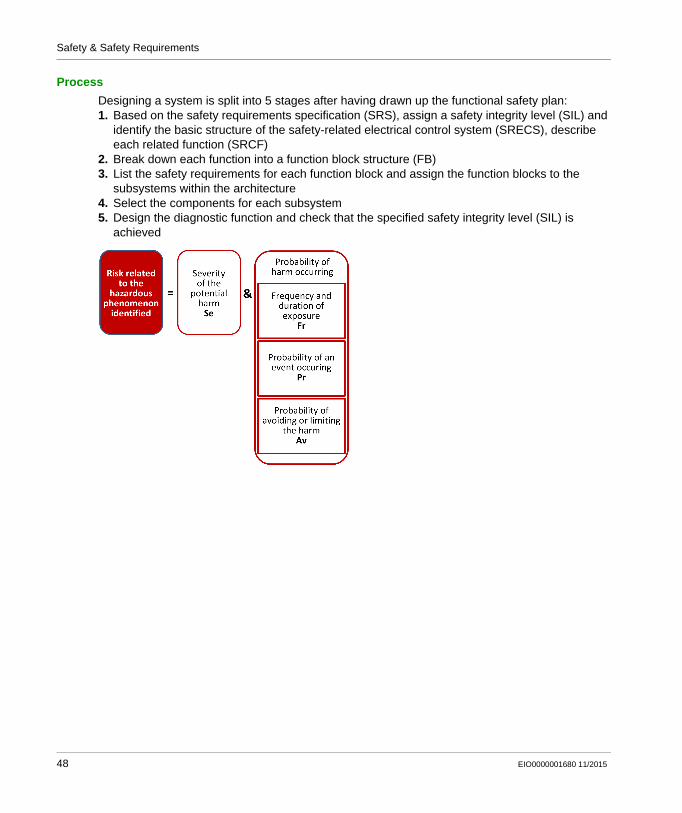
Designing a system is split into 5 stages after having drawn up the functional safety plan:1. Based on the safety requirements specification (SRS), assign a safety integrity level (SIL) and
identify the basic structure of the safety-related electrical control system (SRECS), describe each related function (SRCF)
2. Break down each function into a function block structure (FB)3. List the safety requirements for each function block and assign the function blocks to the
subsystems within the architecture4. Select the components for each subsystem5. Design the diagnostic function and check that the specified safety integrity level (SIL) is
achieved
48 EIO0000001680 11/2015

Safety & Safety Requirements
Stage 1 - Assign a Safety Integrity Level (SIL) and Identify the Structure of the SRECS
Based on the risk assessment performed in accordance with standard EN/ISO 12100, estimation of the required SIL is performed for each hazardous phenomenon and is broken down into parameters, see illustration below.
Severity Se
The severity of injuries or damage to health can be estimated by taking into account reversible injuries, irreversible injuries, and death.
Probability of the harm occurring
Each of the 3 parameters Fr, Pr, Av must be estimated separately using the most unfavorable case. It is strongly recommended that a task analysis model is used in order to ensure that estimation of the probability of the harm occurring is correctly taken into account.
Consequence Severity Se
Irreversible: death, loss of an eye or an arm 4
Irreversible: shattered limb, loss of a finger 3
Reversible: requires the attention of a medical practitioner 2
Reversible: requires first aid 1
EIO0000001680 11/2015 49

Safety & Safety Requirements
Frequency and duration of exposure Fr
The level of exposure is linked to the need to access the hazardous zone (normal operation, maintenance ...) and the type of access (manual feeding, adjustment...). It must then be possible to estimate the average frequency of exposure and its duration.
Probability of occurrence of a hazardous event Pr
2 basic concepts must be taken into account: The predictability of the dangerous components in the various parts of the machine in its various
operating modes (normal, maintenance, troubleshooting), paying particular attention to unexpected restarting
The behavior of the persons interacting with the machine, such as stress, fatigue, inexperience, and so on.
Probability of avoiding or limiting the harm Av
This parameter is linked to the design of the machine. It takes into account the suddenness of the occurrence of the hazardous event, the nature of the dangerous component (cutting, temperature, electrical) and the possibility for a person to identify a hazardous phenomenon.
Frequency of Dangerous Exposure Fr
≤ 1 hour 5
> 1 hour...≤ 1 day 4
>1 day=< 2 weeks 3
2 weeks ≤1 year 2
> 1 year 1
Probability of Occurrence of a Dangerous Event Pr
Very High 5
Probable 4
Possible 3
Almost impossible 2
Negligible 1
Probability of Avoiding or Limiting the Harm Av
Impossible 5
Almost impossible 3
Probable 1
50 EIO0000001680 11/2015

Safety & Safety Requirements
Assignment of the SIL
Estimation is made with the help of the table below. In the example, the degree of severity is 4 because there is a risk of death; this value is shown in the first column of the table.
All the other parameters must be added together in order to select one of the classes (vertical columns in the table below), which gives: Fr = 5; access between 1 hour and a day Pr = 2; low probability of occurrence of the hazardous event (for example, operator monitoring) Av = 3; probability of avoiding almost impossible
Therefore a class CI = 5 + 2 + 3 = 10
A level of SIL 2 must be achieved by the safety-related electrical control systems (SRECS) on the machine.
Basic structure of the SRECS
Without going into detail about the hardware components to be used, the system is broken down into subsystems. In the example, you find the 3 subsystems that will perform the input, processing, and output functions.
The figure below illustrates this stage, using the terminology given in the standard.
Stage 2 - Break down Each Function into a Function Block Structure (FB)
A function block (FB) is the result of a detailed breakdown of a safety-related function. The function block structure gives an initial concept of the SRECS architecture. The safety requirements of each block are deduced from the specification of the safety requirements of the system's function.
EIO0000001680 11/2015 51

Safety & Safety Requirements
Stage 3 - List the Safety Requirements for Each Function Block and Assign the Function Blocks to the Subsystems
Each function block is assigned to a subsystem in the SRECS architecture. A failure of any subsystem will lead to the failure of the safety-related control function.
More than one function block may be assigned to each subsystem. Each subsystem may include subsystem elements and, if necessary, diagnostic functions in order to ensure that anomalies can be detected and the appropriate action taken.
These diagnostic functions (D) are considered as separate functions; they may be performed within the subsystem, by another internal or external subsystem.
Types of subsystem architectures
Stage 4 - Select the Components for Each Subsystem
As the safety integrity level required in the example mentioned above is SIL 2, each of the components must achieve this level.Once the targeted SIL is determined, the components constructing the system from safety-related subsystems (sensor/switch, logic, actuator) have to be selected. The components must have PFHd (probability of dangerous failure per hour) equal to the
required SIL rating needed.
52 EIO0000001680 11/2015

Safety & Safety Requirements
Stage 5 - Design the Diagnostic Function
The SIL of the subsystem depends not only on the components, but also on the architecture selected. In EN 62061, a safety integrity requirement is expressed as a target failure value for the probability of dangerous failure per hour (PFHd) of each safety-related control function (SRCF).
This can be calculated from reliability data for each component or subsystem, and is related to the SIL as shown in table 3 of the standard.
Relationship between SIL and PFHd values
For each of the 4 logical architectures A to D presented above, there is a different formula to calculate the PFHd. The calculation method is complex and will not be presented here (see
EN/IEC 62061 for the formula and the parameters taken into account).
SIL Probability of Dangerous Failures Per Hour (PFHd)
3 ≥10-8<10-7
2 ≥10-7<10-6
1 ≥10-6<10-5
EIO0000001680 11/2015 53

Safety & Safety Requirements
Selecting the Applicable Standard
Overview
In order to be able to select the applicable standard, a common table in both standards gives indications which are summarized below:
Relationship between the performance level (PL) and the safety integrity level (SIL):
Technology Used EN ISO 13849-1Maximum PL
EN/IEC 62061Maximum SIL
Non-electric only, for example, hydraulic e Not covered
Including some electromechanical, example: relays, and/or complex electronics
e (for designated architectures only)
3
Including complex electronics, for example programmable
D 3
PL SIL Probability of Dangerous Failures Per Hour (1/h)
a No correspondence ≥10-5<10-4
b 1 ≥3x10⁻⁶<10-5
c 1 ≥10-6<3x10⁻⁶
d 2 ≥10-7<10-6
e 3 ≥10-8<10-7
54 EIO0000001680 11/2015

Safety & Safety Requirements
More Information Regarding Safety
Overview
To know more about the relevant regulations, take a look to the safety guide:
http://www.schneider-electric.com/download/ww/en/details/10101698-Machine-safety-guide/?reference=DIA4ED1100102EN
Sistema
For support in creating the safety-related calculations in accordance to EN ISO 13849-1, refer to the free software as well as the related Schneider Electric Sistema offer library.
Sistema:
http://www.dguv.de/bgia/en/pra/softwa/sistema/index.jsp
Sistema library:
http://www2.schneider-electric.com/documents/original-equipment-manufacturers/SCHNEIDER-ELECTRIC-SAFETY-EN_2012_09.zip
EIO0000001680 11/2015 55

Safety & Safety Requirements
Safety Chain Solutions
Schneider Electric offers a library of certified safety chain solutions.
Safety chain solutions provide you with a complete document explaining the concept, the used cases, the architecture, wiring diagram as well the complete calculation.
Each of the safety chain solutions is certified by TÜV enabling you to reuse the architectures for your machine and reusing the Sistema calculations as well as the documentation to help certify the machine to the European legislation.
To find more information regarding the safety chain solutions:
http://www2.schneider-electric.com/sites/corporate/en/solutions/oem/machine-safety/safety-selector.page
Using the safety chain solutions provided by Schneider Electric to solve the existing architecture:
Step Action Comment
1 Perform a risk assessment of your machine.
A required performance level (PLr) must be specified for each intended safety function following a risk assessment in accordance to the standard EN ISO 12100.
2 Use the Safety Chain Selector* to find the most appropriated pre-certified architecture.
By answering the questions the most appropriated architectures will be proposed by the tool.
3 Adapt the proposed architecture to meet the needs of your machine risk assessment.
Select other devices to substitute those in the proposed architecture by examining the safety catalog.
4 Create the Systema file based on the used architecture within the Systema tool.
Each architecture, which is provided with the Safety Chain Selector is available as a template in the Systema tool.
5 Adapt the template in the Systema tool based on the adaptations to the architecture and/or substitution of devices done in step 3.
The safety library within the Systema tool contains numerous devices with all required parameters for the calculation.
* Safety Chain Selector: http://www2.schneider-electric.com/sites/corporate/en/solutions/oem/machine-safety/safety-selector.page
56 EIO0000001680 11/2015

Safety & Safety Requirements
6 Adapt the number of machine operations within the Systema file for your machine.
Within the template, default values were set and these have to be adapted in order to match the machine requirements.
7 Re-evaluate the achieved performance level.
Verify that the attained performance level by the control system is greater than or equal to the required performance level resulting from the risk assessment in step 1.
8 Document the relevant changes in the Systema file.
Specific information about the machine, the author, and so on, must be documented.
9 Print the Systema file to be used as part of the machine documentation.
It is necessary to provide the documentation about the risk assessment and the calculation of the machine.
Step Action Comment
* Safety Chain Selector: http://www2.schneider-electric.com/sites/corporate/en/solutions/oem/machine-safety/safety-selector.page
EIO0000001680 11/2015 57

Safety & Safety Requirements
Functional Safety Measures Implemented in this Architecture
Overview
Within the described architecture, there are 2 safety functions covering different risks. These are described in the following sections.
NOTE: The safety functions proposed in this architecture do not provide a preferred safety chain solution for your machine. These are proposals as to how a safety function could be realized.
Emergency Stop - Main Cabinet
In this TVDA, the safety function emergency stop is applied to disconnect the main power supply of all drives which are located in the main cabinet.
This safety architecture is conforming to category 4 EN ISO 13849-1:2008 and is using the stop category 0 in accordance with the standard IEC/EN 60204-1.
The architecture achieves a performance level (PL) of e and a safety integrity level (SIL) of 3.
Used devices:
WARNINGUNINTENDED EQUIPMENT OPERATION
Ensure that a risk assessment is conducted and respected according to EN/ISO 12100 during the design of your machine.
Failure to follow these instructions can result in death, serious injury, or equipment damage.
Device Description
Input 2 channel emergency stop button Harmony XAL K
Logic Modicon TM3 embedded safety module TM3 SAF5R
Output 2 redundant contactors with feedback loop LC1D
58 EIO0000001680 11/2015

Safety & Safety Requirements
Emergency Stop - Remote Cabinet
In this TVDA, a separate safety function emergency stop is applied to disconnect the main power supply of all drives which are located in the remote cabinet.
This safety architecture is conforming to category 4 EN ISO 13849-1:2008 and is using the stop category 0 in accordance with the standard IEC/EN 60204-1.
The architecture achieves a performance level (PL) of e and a safety integrity level (SIL) of 3.
Used devices:
Device Description
Input 2 channel emergency stop button Harmony XAL K
Logic Preventa safety module XPSAF
Output 2 redundant contactors with feedback loop LC1D
EIO0000001680 11/2015 59

Safety & Safety Requirements
60 EIO0000001680 11/2015

Distributed Modbus TCP Logic Controller M251
Hardware
EIO0000001680 11/2015
Hardware
Chapter 4Hardware
Overview
This chapter provides general information about the hardware.
What Is in This Chapter?
This chapter contains the following sections:
Section Topic Page
4.1 Electrical Distribution and Monitoring 62
4.2 Safety Modules 72
4.3 HMI 79
4.4 Controller 86
4.5 Communication 110
4.6 Motor Control 120
4.7 Detection 151
EIO0000001680 11/2015 61

Hardware
Electrical Distribution and Monitoring
Section 4.1Electrical Distribution and Monitoring
What Is in This Section?
This section contains the following topics:
Topic Page
PowerPact H-Frame Circuit Breaker - Hardware 63
Multi 9 System C60 Multi-Standard Range - Hardware 65
Phaseo Power Supply Universal - Hardware 66
iEM31xx Energy Meter Series - Hardware 68
62 EIO0000001680 11/2015

Hardware
PowerPact H-Frame Circuit Breaker - Hardware
Front View
PowerPact H-Frame circuit breaker (15...150 A)
Description
The PowerPact multistandard circuit breakers are designed to help protect electrical systems from damage caused by overloads and short circuits.
Multistandard circuit breakers are available with either thermal-magnetic or Micrologic electronic trip units. Multistandard circuit breakers with thermal-magnetic trip units contain individual thermal (overload) and immediate (short circuit) sensing elements in each pole.
PowerPact multistandard circuit breakers offer high performance and a wide range of interchangeable trip units to protect most applications. Electronic trip units provide highly accurate protection with wide setting ranges and can integrate measurement, metering, and communication functions. They can be combined with the front display module (FDM121) to provide functions similar to a power meter.
Industry-leading multistandard-compliant circuit breakers provide unrivalled reliability for heavy-duty applications. Common catalog numbers, standardized ratings, and a full range of field-installable accessories make product selection, installation, and maintenance easier than ever.
EIO0000001680 11/2015 63

Hardware
For more information, refer to PowerPact Multistandard, Catalogue, LVPED212023EN.
Features Rated current 15...600 A Breaking capacity from 18...65 kA at 480 Vac 3-pole versions 3 frame sizes: PowerPact H (15...150 A), PowerPact J
(150...250 A), and PowerPact L (250...600 A) Thermal-magnetic and electronic protection available for
the entire range Common accessories and auxiliaries with Compact NSX
range Suitable for isolation Switch-disconnector versions available Compliance with IEC 60947-2 and UL 489 Certifications: UL, CSA, CCC
Benefits Multistandard compliant: IEC, UL, CSA, CCC Worldwide available with unique global part numbers Flexible and simple offer, with proven performance With direct access to energy metering and energy efficiency
thanks to the Micrologic control units
Applications Feeder protection and circuit disconnect solutions when a multistandard approach for one global design machine is needed. International & global multi-site OEMs applications Regional OEMs exporting to USA, with production in
different countries, and in need of local support/maintenance.
64 EIO0000001680 11/2015

Hardware
Multi 9 System C60 Multi-Standard Range - Hardware
Front View
Description
The Multi 9 system is designed for OEMs to provide an electric protection of their products or the specific circuits inside the equipment.
This range allows OEMs to offer equipment in compliance with the leading international standards: UL 489, UL 1077 CSA C22.2 No. 5-02, CSA C22.2 No. 235-04 IEC 60947-2 GB 14048-2
It saves space in the switchboard thanks to its small size.
Easy installation on symmetrical DIN rail (35 mm).
It includes ratings that also make it possible to protect low-power circuits.
The setup of circuit protective devices depends on the electrical installation standard. Multi 9 devices (designed for machinery and equipment manufacturers, integrators, panelbuilders, and so on) are tested in accordance with the UL (Underwriter Laboratories) product standard in order to meet the requirements of the NEC (National Electric Code) installation standard, in force in the United States. Multi 9 "UL" products are also tested to ensure compliance with IEC and CSA standards.
For more information, refer to C60 Multi-Standard Range, Catalog, CM909003E.
EIO0000001680 11/2015 65

Hardware
Phaseo Power Supply Universal - Hardware
Front View
Phaseo ABL8RPS24100 power supply
Description
The Phaseo electronic switch mode power supply is designed to provide the DC voltage necessary for the controller and automation system equipment control circuits.
Conforming to IEC standards and UL, CSA, TÜV and C-Tick certified, they are suitable for industrial use.
The ABL8RPS/8WPS range of Phaseo power supplies covers power ratings 72...960 W in 24 Vdc and adapts to most power distribution systems used throughout the world. The same power supply can thus be connected phase to neutral or phase to phase for line supplies ranging 100...500 Vac nominal.
Local or remote diagnostic functions Current limiting or stop in event of an overload Function modules to ensure continuity of service Power reserve for absorbing the transient current peaks
Standards and certifications
UL, CSA, TÜV, C-Tick
Power range 72…960 W
Voltage range Input: 100…500 VacOutput: 24 Vdc
Degree of protection IP 20 conforming to IEC 60529
Dimensions 6 different types (W x H x D):44…165 x 143 x 120…155 mm (1.73…6.5 x 5.63 x 4.72…6.1 in.)
66 EIO0000001680 11/2015
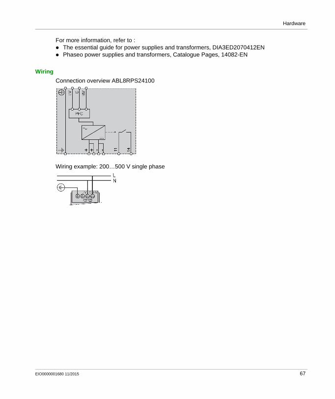
Hardware
For more information, refer to : The essential guide for power supplies and transformers, DIA3ED2070412EN Phaseo power supplies and transformers, Catalogue Pages, 14082-EN
Wiring
Connection overview ABL8RPS24100
Wiring example: 200…500 V single phase
EIO0000001680 11/2015 67

Hardware
iEM31xx Energy Meter Series - Hardware
Front View
The graphic shows the front view of the energy meter iEM3110:
Description
The Acti 9 iEM3100 Energy Meter series offers a cost-attractive, competitive range of DIN rail-mounted energy meters ideal for subbilling and cost allocation applications. Combined with communication systems such as Smart Link, the Acti 9 iEM3100 series makes it easy to integrate electrical distribution measurements into your facility management systems. The Acti 9 iEM3100 series contains 8 versions of energy meter (for example, iEM3110 and iEM3150) to satisfy basic to advanced applications for buildings and industry, data centers, and networks, infrastructure, and so on.
Graphical display for easy viewing Self-powered meters Direct measurement up to 63 A Onboard Modbus, LON, M-Bus or BACnet communication Commissioning safely with ease Compact size
Standards and certifications IEC 61557-12, IEC 61036, IEC 61010, IEC 62053-21/22 class 1 and 0.5S, IEC 62053-23, EN50470-3
Current (max) 63 A
Models iEM3100, iEM3110, iEM3115, iEM3135, iEM3150, iEM3155, iEM3165, iEM3175
68 EIO0000001680 11/2015

Hardware
For more information, refer to iEM3100 series / iEM3200 series, Energy Meters, User Manual, DOCA0005EN.
Wiring
The graphic shows the wiring on three-phase systems for direct measurement of iEM31••
Functions (depending on the model Active energy measurement Electrical measurements such as I, V, P, and so on. Alarm Digital output for pulse MID (legal metrology certification)
Degree of protection front panel: IP40 casing: IP20
Dimensions W x H x D: 90 x 95 x 69 mm (3.54 x 3.74 x 2.72 in.)
EIO0000001680 11/2015 69

Hardware
The graphic shows the connection diagram of iEM3100 / iEM3110 / iEM3115:
70 EIO0000001680 11/2015
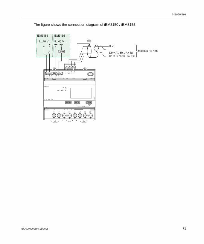
Hardware
The figure shows the connection diagram of iEM3150 / iEM3155:
EIO0000001680 11/2015 71

Hardware
Safety Modules
Section 4.2Safety Modules
What Is in This Section?
This section contains the following topics:
Topic Page
Preventa XPSAF Safety Module - Hardware 73
Modicon TM3 Safety Module - Hardware 75
Preventa Detection and Dialog - Hardware 78
72 EIO0000001680 11/2015

Hardware
Preventa XPSAF Safety Module - Hardware
Front View
Preventa XPSAF safety module
Description
Safety module XPSAF is used for monitoring emergency stop circuits conforming to standards EN/ISO 13850 and EN 60204-1 and also meets the safety requirements for the electrical monitoring of switches on protection devices conforming to standard EN1088/ISO 14119.
3 LEDs which provide information on the monitoring circuit status Manual or automatic start 3 enabling paths, 1 signaling path Feedback loop to monitor external contactors
Maximum achievable safety integrity level
SILCL3 conforming to EN/IEC 62061,PL e/Category 4 conforming to EN/ISO 13849-1
Standards and certifications
EN 60204-1, Cat 4 EN954-1 ISO 13849-1, EN /ISO 14119, EN/ISO 13850, EN50082-2, EN/IEC 60947-5-1, UL, CSA, BG
Power supply 24 Vdc24 Vac
Outputs Relay immediate opening 3 NO, volt-free
Response time on input opening
< 40 ms
Degree of protection Terminals: IP 20Enclosure: IP 40
Dimensions W x H x D: 22.5 x 99 x 114 mm (0.88 x 3.9 x 4.49 in.)
Options Safety relay modules XPSECME and XPSECPE (for increasing the number of safety contacts)
EIO0000001680 11/2015 73

Hardware
For more information, refer to Preventa, Machine Safety Products, MKTED208051EN The essential guide: Preventa machine safety, DIA4ED2041204EN
Wiring
Wiring diagram for module XPSAF
(1) With monitoring of the start button(2) Without monitoring of the start button(3) See technical data for maximum fuse sizeESC External start conditions
74 EIO0000001680 11/2015

Hardware
Modicon TM3 Safety Module - Hardware
Front View
Modicon TM3 safety module
Description
The Modicon TM3 modular I/O system provides flexible and scalable configuration of expansions by direct connection with M221, M241, and M251 controllers. Characterized by easy wiring and maintenance, this modular I/O system offers a wide variety of modules that enables you to meet your desired configuration for reduced costs and simplification.
The Modicon TM3 modular I/O system contains a range of TM3 safety modules. These Modicon TM3 safety modules contain inputs and relay outputs to manage one safety function at a time. The safety function is realized in the module itself and the monitor and control functions are processed by the controller via the TM3 I/O bus.
There are several types of Modicon TM3 safety modules supporting multiple functions. The achievable Performance Level (PL) according to EN/ISO 13849-1:2008 reaches from PL d up to PL e and is dependent on the selected module type and the application.
The module used in the described architecture is the TM3SAF5R. The main characteristics are described in the table below.
Max. Performance Level (PL) / Safety Integrity Level (SIL)
Category 4, PL "e" according to EN/ISO 13849-1: 2008, SIL 3 according to IEC/EN 61508-1:2010
Safety function 2 channel operation with cross circuit detection either with monitored or non-monitored start
Standards and certifications
CEFor more information on the standards and certifications, refer to the Modicon TM3 Safety Modules, Hardware Guide.
Power supply 24 Vdc (-15...+20 %)
Power consumption 3.6 W (power supply), 0.2 W (TM3 I/O bus)
EIO0000001680 11/2015 75

Hardware
Components
Modicon TM3 safety module with removable screw or spring terminal block
For more information, refer to Modicon TM3 Safety Modules, Hardware Guide, EIO0000001831.
Input channels 2 safety inputs and 1 start input (monitored or non-monitored)
Output channels 3 relay outputs normally open controlled together,AC-15: 230 V, 5 A per outputDC-13: 24 V, 4 A per output
Degree of protection IP 20
1 Locking device for attachment to the previous module
2 Status LEDs
3 Expansion connector for I/O bus (one on each side)
4 Power supply and input removable screw terminal block with a 3.81 mm (0.15 in) pitch
5 Relay output removable screw terminal block with a 5.08 mm (0.20 in) pitch
6 Clip-on lock for 35 mm (1.38 in.) DIN-rail
7 Power supply and input removable spring terminal block with a 3.81 mm (0.15 in) pitch
8 Relay output removable spring terminal block with a 5.08 mm (0.20 in) pitch
76 EIO0000001680 11/2015

Hardware
Wiring
Wiring example of emergency stop connection to a TM3SAF5R• module
S1 Emergency stop switch
S2 Start switch
(1) Safety outputs
(2) Monitored start
(3) Non-monitored start
(4) For automatic start, directly connect [S33] and [S39] terminals
(5) Second external device monitoring channel. Connect [S41] and [S42] terminals if not used.
(6) Fuses: Power supply max. 4 A (gG), output max. 4 A (gG) or 6 A (F)
(7) Non-safety related I/O bus communication with logic controller
EIO0000001680 11/2015 77

Hardware
Preventa Detection and Dialog - Hardware
Front View
Preventa product range
Description
Schneider Electric is the provider of the safety chain covering the safety functionality and scalability for your machine. Preventa offers an extensive range of safety-related products, compliant with international standards, designed to provide protection for personnel and equipment.
For more information, refer to Preventa solutions for efficient machine safety - catalogue, MKTED2140201EN.
Complementary safety-related products like light curtains, emergency stop rope pull switches or switches are offered by Telemecanique Sensors; brand of Schneider Electric.
Telemecanique Sensors proposes a number of ranges of safety-related products: Discover this offer on the website: http://www.tesensors.com/global Access to the catalog by product at this URL:
http://www.tesensors.com/global/en/product/catalog/
78 EIO0000001680 11/2015

Hardware
HMI
Section 4.3HMI
What Is in This Section?
This section contains the following topics:
Topic Page
Magelis HMI GTO - Hardware 80
Harmony ZBRN1/ZBRN2 Access Point - Hardware 82
Harmony Control and Signaling - Hardware 85
EIO0000001680 11/2015 79

Hardware
Magelis HMI GTO - Hardware
Front View
Magelis HMI GTO product range
Description
Magelis HMI GTO displays are advanced HMIs with optimized features to improve communication quality. The displays are easy to install and adapt to your environment. Different screen sizes and a complete dimming functionality are available for specific applications. Industry machines for the integration of the Magelis HMI GTO for example are: Compact machines, material handling systems, food and beverage machines, pharmaceutical industry, and so on.
TFT 65 K colors for all screen sizes with energy saving LED backlight Easy connectivity via Ethernet Up-to-date interfaces (USB 2.0, SD cards) to allow easy maintenance and good peripheral links Unique fast connection power plug for the whole range Addition of function keys on the 3.5" and 7" (wide) displays Worldwide certifications including hazardous locations and marine "Bridge and deck" Operating up to 55° C (151° F) for hot environment Stainless steel panel for food and beverage applications available
Standards and certifications
EN 61000-6-4, EN 61000-6-2, UL508, CSA C22.2 n°142
Power supply 24 ± 4.4 Vdc
Degree of protection Depends on the type: IP 65 (IP 67 with addition of a cover) IP 66 K (front panel with stainless steel frame)
Dimensions 8 different types (W x H x D) Min.: 132 x 106 x 42 mm (5.2 x 4.2 x 1.65 in.) Max.: 359 x 285 x 56 mm (14.1 x 11.2 x 2.2 in.)
80 EIO0000001680 11/2015

Hardware
For more information, refer to Magelis GTO, User Manual, EIO0000001133 (ENG).
Wiring
Connector overview GTO3510/4310 and GTO5310/5315
Screen sizes and resolutions
3.5" and 5.7": 320 x 240 pixels (QVGA) 7.0" (wide): 800 x 480 pixels (WVGA) 7.5" and 10.4": 640 x 480 pixels (VGA) 12.1": 800 x 600 pixels (SVGA)
Options Screen protection sheet, environment cover
1 Removable screw terminal block for the 24 Vdc power supply
5 RJ45 connector for RS 485 serial link (COM2)
2 Type A USB host connector for connecting peripherals, transferring applications
6 Slot for SD memory card, with hinged cover
3 Mini-B USB connector for application transfer 7 LED indicating presence of the SD memory card
4 9-way male SUB-D connector for RS 232C serial link (COM1)
8 RJ45 connector for Ethernet TCP/IP link, 10 BASE-T/100BASE-TX with an activity LED
EIO0000001680 11/2015 81

Hardware
Harmony ZBRN1/ZBRN2 Access Point - Hardware
Front View
Harmony ZBRN1 access point
Description
Harmony XB5R wireless and batteryless push buttons are used for remote control with an access point. This allows more flexibility and simplicity in the installation.
The control is realized via radio transmission. Each transmitter is equipped with a "dynamo" generator that converts the mechanical energy produced by pressing the push button into electrical energy.
A radio-coded message with a unique ID code will be sent in a single pulse to one or more receiver(s). These receivers can be located several tens of meters away.
The access points process the received radio frequency inputs and provide these via various communication protocols. They operate as intermediate equipment between a transmitter and a controller. Based on the model the receiver is linked to the controller via RS-485 2 wire serial line (Modbus RTU) or Ethernet (Modbus/TCP).
Wireless and batteryless push-button technology reduces the wiring and hence the cost of installation. They have a wide range of industrial and building applications such as: packing lines automatic doors in logistic centers automobile industries bag filling in cement industries office lighting for efficient usage of the power
Standards and certifications
R&TTE 1995/EC, LVD2006/95/EC, EMC 2004/108/ECEN/IEC 60947-1, EN/IEC 60947-5-1, EN/IEC 60950-1, IEC 61131-2, EN 300440-2, EN 300489-3, EN 300328, EN 62311UL 508 (USA), CSA C22-2 n°14 (Canada), CCC (China), GOST (Russia)
82 EIO0000001680 11/2015

Hardware
For more information, refer to : Harmony XB5R, ZBRN1/ZBRN2, User Manual, EIO0000001177 (EN) Harmony XB5R, Expert Instruction Sheet, EIO0000000812 (EN)
Components
Harmony ZBRN1
Radio certifications FCC (USA), CSA, RSS (Canada), C-Tick (Australia), ANATEL (Brazil), SRRC (China), MIC (Japan)
Agencies UL508, 17th edition, CSA C22.2 No. 142-M2000
Rated voltage 24...240 Vac/Vdc
Degree of protection IP 20
Dimensions W x H x D: 122 x 89 x 63 mm (4.8 x 3.5 x 2.48 in.)
Options Wide range of wireless and batteryless push buttons, external antennas (active or passive)
1 Four 7-segment displays with 5 LEDs 6 External antenna (optional) connector
2 Power LED 7 External antenna (optional) connector protective plug
3 Communication LED 8 ZBRN1:Communication module inserted with 2 RJ45 Ethernet connectors
ZBRN2:2 RJ45 Modbus RS 485 2 wire serial line connectors
4 Radio signal strength LED 9 Jog dial
5 Power input terminal block 10 SD memory card slot
EIO0000001680 11/2015 83

Hardware
Wiring
The power supply voltage allows any common supply connection from 24...240 Vac/Vdc.
84 EIO0000001680 11/2015

Hardware
Harmony Control and Signaling - Hardware
Front View
Harmony product range
Description
Schneider Electric offers a comprehensive range for control and signaling in industrial and commercial applications. All aspects of control and signaling needs are catered for including pilot devices such as push-buttons, indicator lamps, selector switches, and joysticks for standard hole cutouts.
For more information, refer to Control and signaling components, MKTED208031EN.
EIO0000001680 11/2015 85

Hardware
Controller
Section 4.4Controller
What Is in This Section?
This section contains the following topics:
Topic Page
Modicon M251 Logic Controller - Hardware 87
Modicon TM3 Modules - Hardware 91
TM3XTYS4 TeSys Module - Hardware 93
Modicon OTB - Hardware 99
Modicon TM2 Modules - Hardware 102
Advantys ETB I/O Module - Hardware 105
86 EIO0000001680 11/2015

Hardware
Modicon M251 Logic Controller - Hardware
Front View
Modicon M251 Logic Controller
Description
The Modicon M251 Logic Controller has various powerful features and can service a wide range of applications. Software configuration, programming, and commissioning are accomplished with the SoMachine software.
Thanks to the SoMachine software platform it offers optimized solutions for speed control, counting, axis control and communication functions.
The SoMachine software, used to configure and program the Modicon M251 Logic Controller, supports the following IEC61131-3 programming languages for use with these controllers: IL: Instruction List ST: Structured Text FBD: Function Block Diagram SFC: Sequential Function Chart LD: Ladder Diagram
SoMachine software can also be used to program this controller using CFC (Continuous Function Chart) language.
The Modicon M251 Logic Controller native communication ports include (depending on the controller reference): Ethernet USB programming Serial line CANopen Master
EIO0000001680 11/2015 87

Hardware
All controllers support up to 13 application program tasks with the following limits: 3 cyclic tasks: one is configured by default (MAST) 1 freewheeling task 8 event tasks 1 external event task
For more information, refer to : Modicon M251 Logic Controller, Hardware Guide, EIO0000001486 Modicon M251 Logic Controller, Programming Guide, EIO0000001462
Modicon M251 Logic Controllers
Standards and certifications IEC/EN 61131-2, UL 508
Rated voltage 24 Vdc
Degree of protection IP 20
Memory RAM: 64 Mbytes, of which 8 Mbytes available for the application - to execute the applicationFlash: 128 Mbytes - to save the program and data in case of power interruption
Dimensions Device-dependent (W x H x D):54 x 90 x 90 mm (2.12 x 3.54 x 3.54 in.)]
Options SD card TM2 I/O modules TM3 I/O modules TM4 communication modules
Device Digital inputs
Digital outputs
Communication ports
TM251MESC 0 0 1 serial line port1 USB mini-B programming port2 Ethernet switched ports1 CANopen port
TM251MESE 0 0 1 serial line port1 USB mini-B programming port2 Ethernet switched ports1 Ethernet port for fieldbus
88 EIO0000001680 11/2015

Hardware
Physical Overview
Modicon TM251MESE logic controller
1 2 Ethernet switched ports 9 USB mini-B programming port
2 Ethernet port 2 10 Screwing plate
3 Serial line port 11 Clip-on lock for 35 mm (1.38 in) top hat section rail (DIN-rail)
4 Run/Stop switch 12 24 Vdc power supply
5 Status LEDs 13 Protective cover
6 TM4 bus connector 14 Locking hook
7 TM3/TM2 bus connector 15 Battery holder
8 SD card slot - -
EIO0000001680 11/2015 89

Hardware
Wiring Power Supply
* Type T fuse
90 EIO0000001680 11/2015

Hardware
Modicon TM3 Modules - Hardware
Front View
Modicon TM3 Modules
Description
The Modicon TM3 modular I/O system provides flexible and scalable configuration of expansions by direct connection with M221, M241, and M251 controllers. Characterized by easy wiring and maintenance, this modular I/O system offers a wide variety of modules that enables you to meet your desired configuration for reduced costs and simplification.
Flexible and scalable I/O configuration: Local or remote expansion via the local TM3 expansion bus on M221, M241, and M251
controllers. Wide range of I/O expansion modules: Digital I/O modules Analog I/O modules Expert I/O modules Safety I/O modules Transmitter and receiver modules
EIO0000001680 11/2015 91

Hardware
Simplified maintenance installation: Embedded diagnostics for local and distant supervision Wiring simplicity: spring terminals, removable terminal blocks
For more information, refer to Modicon TM3, Expansion Modules Configuration, Programming Guide, EIO0000001402.
Wiring
Wiring example TM3DM8R
* Type T fuse(1) The COM0 and COM1 terminals are not connected internally.(2) To improve the life time of the contacts, and to protect from potential inductive load damage, you must
connect a free wheeling diode in parallel to each inductive DC load or an RC snubber in parallel of each inductive AC load.
A Sink wiring (positive logic)B Source wiring (negative logic)C Source wiring (positive logic)D Sink wiring (negative logic)
Standards and certifications
IEC/EN 61131-2 ed. 3 2007, UL 508, CSA 22.2 No. 142, CE
Power supply 24 Vdc or 120 Vac** only TM3DI8A
Degree of protection IP 20
Dimensions One assembled integral module (W x H x D):21.4…42.9 x 94.5…95 x 81.3…88.1 mm (0.84…1.69 x 3.72…3.74 x 3.2…3.47 in.)
92 EIO0000001680 11/2015

Hardware
TM3XTYS4 TeSys Module - Hardware
Front View
Description
The TM3XTYS4 I/O expansion module connects the controller to the parallel wiring system of TeSys. This I/O expansion module provides the status and command information for each TeSys motor starter via an RJ45 connector. One TM3XTYS4 module can manage up to 4 TeSys motor starters, reverse or forward, whatever they are TeSys D or TeSys U or mix.
The TM3XTYS4 module is compatible with: TeSys U system equipped with the LUFC00 parallel wiring module GV and TeSys D system equipped with the LAD5C•• wiring adapter
The TM3XTYS4 module provides: 4 channels each with an RJ45 connector Each channel provides: 3 sink transistor inputs (24 Vdc type 1 (IEC/EN 61131-2)) 2 source transistor outputs (24 Vdc / 0.3 A)
Removable 24 Vdc power supply terminal block
For more information, refer to Modicon TM3, Expert I/O Modules, Hardware Guide, EIO0000001420
EIO0000001680 11/2015 93

Hardware
Physical Overview
I/O Channel RJ45 Connector
The TM3XTYS4 module is equipped with 4 channel RJ45 connectors.
1 LEDs for displaying the state of the I/O channels
2 TeSys RJ45 connectors
3 Removable power supply screw terminal block
4 Clip-on lock for 35 m (1.38 in) top hat section rail (DIN-rail)
5 Expansion connector for I/O bus.
6 Locking device for attachment to the previous module
94 EIO0000001680 11/2015

Hardware
Pin Assignment
RJ45 connector
Pin Type Signal Description
1 Output 1 Direction 1 control Drives to direct (forward) command of the motor
2 Output 2 Direction 2 control Drives to direct (backward) command of the motor
3 0 V - -
4 Input 1 Ready Active if the selector of the TeSys is in the ON position
5 Input 2 Run Input active if the power contacts of TeSys are closed.
6 N.C. - Reserved. Do not connect.
7 Input 3 Trip Input active if the selector of TeSys is in the TRIP position (only for TeSys U).
8 24 Vdc input common
Common for sensors Power supply for inputs 1, 2 and 3 (pins 4, 5 and 7).
WARNINGUNINTENDED EQUIPMENT OPERATION
Do not connect wires to unused terminals and/or terminals indicated as “No Connection (N.C.)”.
Failure to follow these instructions can result in death, serious injury, or equipment damage.
CAUTIONINCOMPATIBLE EQUIPMENT
Use the RJ45 connector only for the link with devices which are compatible with the TeSys RJ45 connection system.
Failure to follow these instructions can result in injury or equipment damage.
EIO0000001680 11/2015 95

Hardware
DC Power Supply Wiring Diagram
* Type T fuse24 Vdc Is dedicated to outputs power supply24 Vdc Aux Is dedicated to inputs power supply
96 EIO0000001680 11/2015
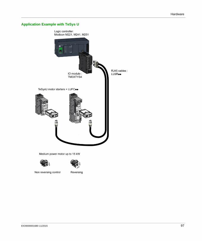
Hardware
Application Example with TeSys U
EIO0000001680 11/2015 97

Hardware
Application Example with TeSys D
98 EIO0000001680 11/2015

Hardware
Modicon OTB - Hardware
Front View
Modicon OTB series
Description
Modicon OTB optimized distributed I/O allows the creation of I/O islands managed by a master controller via a fieldbus or communication network. With its expandable block type architecture, the Modicon OTB is ideally suited for small and medium size islands of distributed I/O that can be placed closer to the sensors and actuators they control, reducing wiring time and costs. The Modicon OTB solution includes 3 communication bases (interface modules) for the various types of fieldbus, CANopen, Modbus TCP/IP, or Modbus RS 485 serial line.
Expandable with up to 7 TM2 expansion modules A wide range of I/O expansion modules Sensor/actuator connection using removable screw terminals Direct mounting on DIN rail Ideal compactness: 20 I/Os within a width of 55 mm (2.17 in.), including bus connection Reduces installation time and wiring costs
Standards and certifications CSA, CSA C22.2 No. 213 (Class 1 division 2 groups A), CSA C22.2 No. 213 (Class 1 division 2 groups B), CSA C22.2 No. 213 (Class 1 division 2 groups C), CSA C22.2 No. 213 (Class 1 division 2 groups D), EN 61131-2, IEC 41131-2, UL508
power supply 24 Vdc
Degree of protection IP20
Embedded I/Os 12 digital inputs 8 digital outputs
Dimensions W x H x D:55 x 99 x 70 mm (2.17 x 3.9 x 2.76 in.)
EIO0000001680 11/2015 99

Hardware
For more information, refer to : Advantys OTB CANopen, Remote Inputs and Outputs, User Manual, 1606384 Advantys OTB Ethernet, Remote Inputs/Outputs, User Manual, 1606385 Modbus Advantys OTB, Remote Inputs/Outputs, User Manual, 1606383
Electrical Installation
Wiring example: power supply
Grounding wire length should not exceed 80 mm (3.15 in.)
The sensor/actuator cables must be shorter than 30 m (98.4 ft.)
100 EIO0000001680 11/2015

Hardware
Wiring example: OTB 1•0DM9LP modules
Output points 0 and 1 are source transistor outputs, all other output points are relay. The COM terminals are not connected together internally. Connect an appropriate fuse for the load.
EIO0000001680 11/2015 101

Hardware
Modicon TM2 Modules - Hardware
Front View
Modicon TM2 expansion modules
Description
The range of Modicon TM2 expansion modules includes analog I/O modules, digital I/O modules, expert expansion modules, and communication expansion modules. Characterized by easy wiring and maintenance, these expansion modules offer a wide choice of modularity and so a large variety of automation configurations. The modules can be used in combination with 4 platforms: M238 bases, Modicon OTB, HMI controllers, and Twido bases.
The analog I/O expansion modules are compatible with sensors and suitable for economic and easy to use measurement. The digital I/O expansion modules are available in 3 wiring modes: screw terminals, high-density connectors, and spring terminals. The expert expansion modules are used for high speed counting in repetitive processes with advanced features like reflex outputs for enhanced accuracy.
Fits customer application in the targeted market segments High level of quality and performance High EMC immunity for all modules Inputs and DC transistor outputs protected against short-circuits and polarity inversions All TM2 modules are RoHS compliant Low standard cost
Standards and certifications
Depends on the module:CE UL CSA UL/CSA class I, Div. 2, TÜV IEC EN 61131-2 edition 2 2003, cULus, Nemko - GL - LR - DNV
Power supply Depends on the module:24 Vdc or 120 Vac
Degree of protection IP20
102 EIO0000001680 11/2015

Hardware
For more information, refer to Modicon TM2, Analog I/O Modules, Hardware Guide, EIO0000000034 Modicon TM2, Digital I/O Modules, Hardware Guide, EIO0000000028 Modicon TM2, High Speed Counter Modules, Hardware Guide, EIO0000000022
Wiring
For a brief overview, refer to the 2 wiring examples below.
Wiring example TM2AMM3HT analog mixed I/O module
(1) Voltage/current preactuator
Dimensions Depends on the module:(W x H x D):21.2...42.9 x 90 x 95.6...117.2 mm (0.84...1.69 x 3.54 x 3.76...4.61 in.)
EIO0000001680 11/2015 103

Hardware
Wiring example: TM2DMM8DRT digital mixed I/O module
(1) Protection for inductive loadA Sink wiring (positive logic)B Source wiring (negative logic)
104 EIO0000001680 11/2015

Hardware
Advantys ETB I/O Module - Hardware
Front View
Advantys ETB IP 67 Ethernet block I/O module
Description
The Advantys ETB family of I/O modules includes modules designed for use with either the Modbus TCP/IP or the Ethernet IP protocols. This architecture includes a module designed for the Modbus TCP/IP protocol.
Advantys ETB I/O modules combine the functionality of a block I/O with an embedded 2-port Ethernet switch. These modules can be used in applications where I/O is mounted directly on equipment without an enclosure. They can be exposed to water or oil spray.
Each Advantys ETB I/O module is housed in an IP 67 rated enclosure that when properly installed (according to IEC 60529) provides protection against the ingress of: Dust Water (when temporarily immersed (for up to 30 minutes) to a depth of 1 meter)
Module data is accessible via Modbus messaging and embedded webpages, and includes: Input and output data Input and output status I/O configuration settings Module Ethernet (Modbus TCP/IP) communication configuration settings Module firmware data
EIO0000001680 11/2015 105

Hardware
For more information, refer to Advantys ETB, IP67 Ethernet Block I/O Modules for Modbus TCP/IP, User Guide, EIO0000000158
Components
The front face of the module includes the mounting holes, connectors, port connector labels, LEDs, push buttons, and the HMI display. The details and locations of these features are shown below.
Standards and certifications UL, CUL, CE mark
Power supply 24 Vdc
Temperature Operation: -25...+70 °C (-13...+158 °F) Storage: -40...+85 °C (-13...+158 °F)
Inputs/outputs ETB1EM16EPPO: 16/0 ETB1EM08E08SPP0: 8/8 ETB1EM12E04SPPO: 12/4 ETB1EM16CP00: 16 configurable input and output points
Output current 2.0 A / point sum = 8 A
Short circuit current (typical) 6.5 A
Output switching frequency 200 Hz
Dimensions W x H x D: 60 x 270 x 37 mm (2.4 x 8.7 x 1.5 in)
Degree of protection IP 67 according to IEC 60529
106 EIO0000001680 11/2015

Hardware
Pin Assignment of the Connectors
Power connectors
The pin assignments for the power connectors are outlined in the following figure, with the male on the left and the female on the right.
1 Five mounting holes, including the center one
2 Two 5-pin power connectors including input (left) and output (right) to connect the next module in the system (7/8 mini-change cables)
3 Three power LEDs: [O] = output; [PWR] = not used; [I] = both input and module
4 Sixteen I/O point LEDs
5 Eight 5-pin I/O port connectors numbered from bottom to top (M12 or ultra-Lock M12 cables)
6 Eight white port labels
7 Two buttons for selecting the method of IP address assignment
8 Four-character scrolling display
9 Two link LEDs
10 Two 4-pin Ethernet network connectors (M12 D coded cables)
1 Output power 0 Vdc
2 Module/input power 0 Vdc
3 Protective earth ground (PE)
4 Module/input power 24 Vdc
5 Output power 24 Vdc
EIO0000001680 11/2015 107

Hardware
I/O Port Connectors
The following figure displays an ETB I/O port connector on the left of the module and its corresponding point assignments. The port connectors on the right side of the module are rotated 90 ° counter-clockwise from the ones on the left.
Ethernet Network Connectors
The following figure shows the pin assignments of the two Ethernet network connectors on the module.
1 +24 Vdc
2 Point B input or output
3 GND
4 Point A input or output
5 Protective earth ground (PE)
1 TX+ (Ethernet transmit line +)
2 RX+ (Ethernet receive line +)
3 TX- (Ethernet transmit line -)
4 RX- (Ethernet receive line -)
108 EIO0000001680 11/2015

Hardware
Installation Example
This diagram shows you an example of how to arrange your Advantys ETB I/O modules in a daisy-chain topology.
1 Cabinet-mounted PLC
2 Ethernet interface module on PLC system
3 Ethernet adapter
4 Ethernet connector cable
5 24 Vdc power supply
NOTE: Alternatively, the power supply could be mounted in the cabinet.
6 Power supply cable
7 Machine
8 Advantys ETB I/O modules mounted on machine
EIO0000001680 11/2015 109
Hardware
Communication
Section 4.5Communication
What Is in This Section?
This section contains the following topics:
Topic Page
ConneXium Ethernet Switch (Managed) - Hardware 111
ConneXium Ethernet Switch (Unmanaged) - Hardware 115
ConneXium Ethernet Switch (Unmanaged) IP 67 - Hardware 117
110 EIO0000001680 11/2015

Hardware
ConneXium Ethernet Switch (Managed) - Hardware
Front View
8-port TCSESM083F23F0 switch
EIO0000001680 11/2015 111

Hardware
Description
The ConneXium managed switch range is comprised of products required to build the infrastructure of an industrial Ethernet network.
Managed devices are those which there is possibility to configure or control the parameters of the device (manage them) and to access to its internal information. They provide features that improve performance, network, and diagnostics efficiency.
They support Ethernet 10 Mbit/s and Fast Ethernet 100 Mbit/s.
Furthermore the switch modules support switched Ethernet networks in accordance with IEEE standard 802.3 or 802.3u using copper and fiber optic technology.
All switches are mounted on a standard DIN rail.
Managed Ethernet switch with user configurated services and features Web based configuration Network configurations include line, star, mesh, or ring structures Automatic negotiation of 10/100 Mbit/s and duplex mode Redundancy protocols that include HIPER-ring, MRP and RSTP Quality of service traffic class prioritization Remote monitoring of operation
For more information, refer to ConneXium TCSESM Managed Switch, Installation Manual, 31007118.
Standards and certifications
EN/IEC 61131-2, UL508 & 1604, CSA C22.2 No. 14 & No. 213, C-Tick, GL
Power supply 24 Vdc
Operating voltage range 9.6...60 Vdc or 18...30 Vdc
Ports 4,8,10,16, 24
Degree of protection IP 20
Dimensions W x H x D:47/74/111 x 131 x 111 mm (1.85/2.91/4.37 x 5.13 x 4.37 in.)
112 EIO0000001680 11/2015

Hardware
Physical Overview
Connector overview of the TCSESM083F23F0
1 Plug-in terminal block for power supply 6 MAC address field
2 LED display elements 7 Ports in compliance with 10/100BASE-T(X) (RJ45)
3 2-pin DIP switch 8 Protective earth ground (PE)
4 USB interface 9 IP address field
5 V.24 connection for external management 10 Port 1 + port 2:Twisted-Pair T(X), RJ45, 10/100 Mbit/sMulti-mode FX, DSC, 100 Mbit/sSingle-mode FX, DSC, 100 Mbit/s
EIO0000001680 11/2015 113

Hardware
Wiring Supply Voltage and Signal Contact
Redundant power supplies can be used. Both inputs are uncoupled. There is no distributed load.
With redundant supply, the power supply unit supplies the device only with the higher output voltage.
The supply voltage is electrically isolated from the housing.
You can choose between DC or AC voltage when connecting the supply voltage.
1 DC voltage, voltage range: 9.6 Vdc...60 Vdc2 AC voltage, voltage range: 18 Vac...30 Vac
The signal contact "FAULT" monitors the functioning of the device, thus enabling remote diagnostics. You can specify the type of function monitoring in the management.
A break in contact is used to report the following conditions via the potential-free signal contact (relay contact, closed circuit): The detected inoperability of at least one of the 2 voltage supplies (voltage supply 1 or 2 is below
the threshold value). The loss of connection for at least one port. The report of the link status can be masked by the
management for each port. In the delivery state, link status monitoring is deactivated. The loss of ring redundancy reserve. A detected error during the self-test.
114 EIO0000001680 11/2015

Hardware
ConneXium Ethernet Switch (Unmanaged) - Hardware
Front View
5-port TCSESU053FN0 Ethernet switch (unmanaged)
Description
The ConneXium unmanaged Ethernet switch range offers you a smart and flexible way to integrate Ethernet solutions into your operation, from the device level to the control network and to your corporate network.
Unmanaged devices are those which there is no possibility to configure or control any of the parameters of the devices. They support Ethernet 10 Mbit/s and Fast Ethernet 100 Mbit/s.
Furthermore the switch modules support switched Ethernet networks in accordance with IEEE standard 802.3 or 802.3u using copper and fiber optic technology.
All switches are mounted on a standard DIN rail.
Multi-address capability Storage and rerouting of received data Data packets with VLAN tags are transmitted unchanged (IEEE 802.1 Q) Automatic negotiation of 10/100 Mbit/s and duplex mode Automatic change of polarity Low-cost wiring solution
EIO0000001680 11/2015 115

Hardware
For more information, refer to ConneXium Ethernet Switches, TCSESU0••F•N0, Quick Reference Guide, 31007950.
Wiring
TCSESU053FN0 connector overview
1 3-pin terminal block for power supply2 Power indicator3 10/100 base-TX (RJ45 connectors)4 Port ACT/LNK LEDs
Standards and certifications
UL508, CSA 22.2 No.142, CE
Power supply 24 Vdc
Operating voltage 9.6...32 Vdc
Ports 3, 4, 5,8
Degree of protection IP 30
Dimensions W x H x D: 25 x 114 x 79 mm (0.98 x 4.49 x 3.1 in.)(TCSESU053FN0)
116 EIO0000001680 11/2015

Hardware
ConneXium Ethernet Switch (Unmanaged) IP 67 - Hardware
Front View
ConneXium Ethernet 5TCSESU051F0 switch
Description
The ConneXium 5TCSESU051F0 switch has been especially designed for use in industrial environments.
According to EN 620529 the Ethernet switch has a degree of protection of IP 67.
It supports Ethernet 10 Mbit/s and Fast Ethernet 100 Mbit/s.
The switch module supports switched Ethernet networks in accordance with IEEE standard 802.3 (10BASE-T) or 802.3u (100BASE-TX) using copper technology.
The ConneXium 5TCSESU051F0 switch has five 10/100 Mbit/s twisted-pair ports (10BASET/100BASE-TX, shielded M12 connectors).
EIO0000001680 11/2015 117

Hardware
It is mounted at the installation site using screws.
Multi-address capability Storage and rerouting of received data Data packets with VLAN tags are transmitted unchanged (IEEE 802.1 Q) Automatic negotiation of 10/100 Mbit/s and duplex mode Automatic change of polarity Protected against shock and foreign particles Dust proof Water protected (temporary immersion)
For more information, refer to : ConneXium Industrial Ethernet Cabling System, 5TX IP67 Switch, TCSESU051F0, 31006691 ConneXium Ethernet Switches, TCSESU0••F•N0, Quick Reference Guide, 31007950
Standards and certifications
UL508, CSA 22.2 No.14 (cUL mark), CE
Power supply 24 Vdc
Ports 5
Degree of protection IP 67
Dimensions W x H x D:60 x 126 x 31 mm (2.36 x 4.96 x 1.22 in.)
118 EIO0000001680 11/2015

Hardware
Physical Overview
Connector overview of the TCSESU051F0
1 Power supply connector2 Power LED3 Ethernet connector4 Port status LED
EIO0000001680 11/2015 119

Hardware
Motor Control
Section 4.6Motor Control
What Is in This Section?
This section contains the following topics:
Topic Page
TeSys D Contactor - Hardware 121
TeSys GV2 Motor Circuit Breakers - Hardware 123
TeSys U LU2B Motor Starter- Hardware 125
TeSys GV2DP - Hardware 129
TeSys LAD5Cxx Wiring Adapter - Hardware 131
Altistart 01 Soft Starter - Hardware 133
Altivar 12 Variable Speed Drive - Hardware 136
Altivar 32 Variable Speed Drive - Hardware 140
Lexium 32M Servo Drive - Hardware 144
Lexium BSH/BMH Servo Motors - Hardware 149
120 EIO0000001680 11/2015

Hardware
TeSys D Contactor - Hardware
Front View
TeSys D-LC1D contactor
Description
TeSys D-LC1D contactors are designed for all power switching, control applications, and integration into control systems.
They conform to standard IEC 60947-4-1, for utilization categories AC6b, as well as to UL/CSA standards.
This product constitutes a ready-to-use solution and offers you quick simple setup.
TeSys D contactors can be used to create motor starters for any type of application.
AC, DC, and low-consumption DC control circuit All types of starter: reversing or non-reversing, star/delta, by auto-transformer, and so on. Various connectors: spring terminal, EverLink terminal block, screw clamp, ring-type
connection, faston connector Easy and simple direct mounting between contactor and circuit breaker, according to EverLink
terminal block (40...65 A)
Standards and certifications IEC/EN 60947-4-1, IEC/EN 60947-5-1, UL 508, CSA C22.2 n°14, UL, CSA, CCC, GOST, GL, DNV, RINA, VB, LROS
Rated operational current (Ie)I in AC-3 (Ue max. 440 V)
9…150 A
Rated control circuit voltage (Uc) 12(24*)…690(500*) Vac12(24*)…440 Vdc*D115 and D150
Degree of protection (front face) IP 20 (conforming to IEC 60529)
Protective treatment "TH" (conforming to IEC 60068-2-30)
EIO0000001680 11/2015 121

Hardware
For more information, refer to Control and protection components, MKTED210011EN.
Wiring
TeSys D09…150 3-pole contactors wiring diagram
Dimensions 19 different types without add-on blocks or cover (WxHxD):45…155 x 77…158 x 84…132 mm (1.77…6.1 x 3.0…6.22 x 3.3…5.2 in.)
Options Various connector types, wide range of auxiliary contact blocks and modules, power connection accessories, suppressor modules
122 EIO0000001680 11/2015

Hardware
TeSys GV2 Motor Circuit Breakers - Hardware
Front View
TeSys GV2 P motor circuit breaker
Description
The large TeSys motor circuit-breakers range GV2, GV3 and GV7 is categorized according to their level of performance and functions. Due to its diverse characteristics, only the GV2 P is presented and integrated into the TVDA.
The TeSys GV2 P motor circuit-breakers are three-pole thermal-magnetic circuit-breakers designed for the control and protection of motors.
The motor protection is provided by the thermal-magnetic elements incorporated in the industrial motor circuit-breaker.
The magnetic elements (short-circuit protection) have a non-adjustable tripping threshold, which is equal to 13 times the maximum setting current of the thermal trips.
The thermal elements (overload protection) include automatic compensation for ambient temperature variations. The addition of an under voltage trip allows the circuit-breaker to be de-energized in the event of an under voltage condition.
Motor and personnel protection Live parts are protected from direct finger contact Compact size Easy to install: screw mounting or clip-on mounting Control by rotary knob Connection by screw clamps
Standards and certifications
IEC 60947-1, 60947-2, 60947-4-1, EN 60204, UL508, CSA C 22.2 n° 14-05, NF C 63-650, 63-120, 79-130, VDE 0113, 0660, UL*, CSA, PTB, EZU, GOST, TSE, DNV, LROS, GL, BV, RINA, CCC, ATEX *UL508 type E for GV2 P••H7 (line spacer included)
Operational voltage 690 V
EIO0000001680 11/2015 123

Hardware
For more information, refer to Control and protection components, MKTED210011EN.
Wiring
TeSys GV2 P contactors wiring diagram
Degree of protection IP 20
Dimensions W x H x D: 44.5 x 89 x 97 mm (1.75 x 3.5 x 3.82 in.)
Options Combination block Sets of 3-pole busbars Protective end cover Terminal blocks Padlock able external operator Contact blocks: Error signaling contact and immediate auxiliary contacts Undervoltage/Shunt trips Padlocking devices
124 EIO0000001680 11/2015

Hardware
TeSys U LU2B Motor Starter- Hardware
Front View
TeSys U LU2B•• motor starter
Description
The TeSys U starter-controller is a Direct On Line (D.O.L.) starter which performs the following functions: Protection and control of single-phase or three-phase motors: isolation and breaking function overload and short-circuit protection thermal overload protection power switching
Control of the application: protection function indication application monitoring (running time, number of errors detected, motor current values, and
so on) logs (last five errors detected are saved, along with motor parameter values)
These functions can be added by selecting control units and function modules which clip into the power base. This late customization is also possible after power and control circuit wiring has been completed.
EIO0000001680 11/2015 125
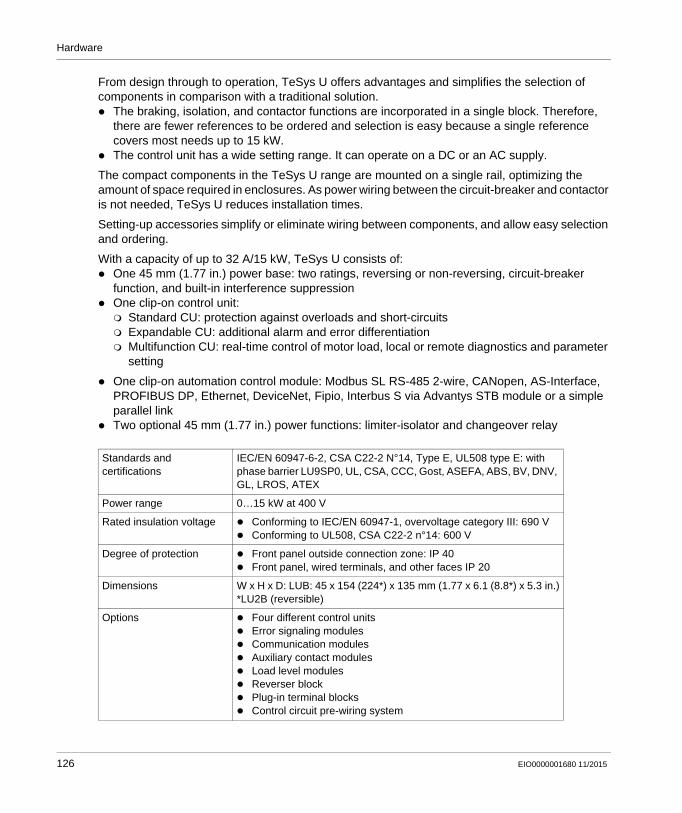
Hardware
From design through to operation, TeSys U offers advantages and simplifies the selection of components in comparison with a traditional solution. The braking, isolation, and contactor functions are incorporated in a single block. Therefore,
there are fewer references to be ordered and selection is easy because a single reference covers most needs up to 15 kW.
The control unit has a wide setting range. It can operate on a DC or an AC supply.
The compact components in the TeSys U range are mounted on a single rail, optimizing the amount of space required in enclosures. As power wiring between the circuit-breaker and contactor is not needed, TeSys U reduces installation times.
Setting-up accessories simplify or eliminate wiring between components, and allow easy selection and ordering.
With a capacity of up to 32 A/15 kW, TeSys U consists of: One 45 mm (1.77 in.) power base: two ratings, reversing or non-reversing, circuit-breaker
function, and built-in interference suppression One clip-on control unit: Standard CU: protection against overloads and short-circuits Expandable CU: additional alarm and error differentiation Multifunction CU: real-time control of motor load, local or remote diagnostics and parameter
setting
One clip-on automation control module: Modbus SL RS-485 2-wire, CANopen, AS-Interface, PROFIBUS DP, Ethernet, DeviceNet, Fipio, Interbus S via Advantys STB module or a simple parallel link
Two optional 45 mm (1.77 in.) power functions: limiter-isolator and changeover relay
Standards and certifications
IEC/EN 60947-6-2, CSA C22-2 N°14, Type E, UL508 type E: with phase barrier LU9SP0, UL, CSA, CCC, Gost, ASEFA, ABS, BV, DNV, GL, LROS, ATEX
Power range 0…15 kW at 400 V
Rated insulation voltage Conforming to IEC/EN 60947-1, overvoltage category III: 690 V Conforming to UL508, CSA C22-2 n°14: 600 V
Degree of protection Front panel outside connection zone: IP 40 Front panel, wired terminals, and other faces IP 20
Dimensions W x H x D: LUB: 45 x 154 (224*) x 135 mm (1.77 x 6.1 (8.8*) x 5.3 in.)*LU2B (reversible)
Options Four different control units Error signaling modules Communication modules Auxiliary contact modules Load level modules Reverser block Plug-in terminal blocks Control circuit pre-wiring system
126 EIO0000001680 11/2015

Hardware
For more information, refer to : Control and protection components, MKTED210011EN TeSys U, Starter-controllers, Catalogue, DIA1ED2081003EN
Components
TeSys U - non-reversing
1 Power supply terminal block2 On/Off/Reset control handle3 "Motor" terminal blockA Power baseB Control unitsC Auxiliary contact modules (LUF), thermal overload signaling, error signaling modules, or load level
modulesD Communication modulesE Auxiliary contact module (LUA)F Terminal block
EIO0000001680 11/2015 127

Hardware
TeSys U - reversing
A Reverser blockB Plug-in terminal blocksC Control circuit pre-wiring system
A preassembled reversing power base can be ordered by a specific part number.
Wiring
TeSys U - reversing
128 EIO0000001680 11/2015

Hardware
TeSys GV2DP - Hardware
Front View
TeSys GV2DP
Description
The Schneider Electric TeSys product range offers a wide range of pre-assembled automatic motor starter combinations with a power rate of up to 15 kW at 400/415 Vac. Motor starter combinations with higher power ratings are available for customer assembly.
The product range of the TeSys GV2D•••••• motor starter combinations offers you a quick and simple selection and product compatibility. The TeSys D contactor, when combined with the TeSys GV2 motor circuit-breaker, provides a compact motor starter solution.
Range description Direct On Line (D.O.L.) or reversing starters, 45 mm (1.77 in), and 90 mm (3.54 in) wide
respectively Motor circuit-breaker with control via push-buttons (GV2ME) or selector switch (GV2P) Circuit-breaker with built-in overload protection Type 1 or type 2 coordination Breaking capacity up to 130 kA Enclosure for thermal-magnetic circuit breakers TeSys GV2ME
Each pre-assembled combination comprises: 1 motor circuit breaker GV2ME or GV2P 1 3-pole contactor LC1D or LC2D 1 combination block GV2AF3
For more information, refer to : The essential guide, TeSys for power control & protection, DIA1ED2040401EN Control and protection components, MKTED210011EN
EIO0000001680 11/2015 129

Hardware
Wiring
130 EIO0000001680 11/2015

Hardware
TeSys LAD5Cxx Wiring Adapter - Hardware
Front View
Description
The TeSys LAD5C•• wiring adapter makes the TeSys motor starter combinations with screw-clamp terminals compatible to the RJ45 connection system.
The RJ45 connection system offers a quick and easy connection to the TM3 I/O expansion module TM3XTYS4.
All the control and command terminals of the motor starter combination are individually connected to the adapter with pre-shaped pins. The upstream liaison with the TM3XYS4 module is carried out with a simple RJ45 preformed cable.
4 types of the wiring adapter are available:
Reference Motor control Motor starter combination
LAD5C11 Non-reversing GV2ME/GV2P with LC1D09BL to LC1D32BL
LAD5C12 Reversing GV2ME/GV2P with LC2D09BL to LC2D32BL
LAD5C31 Non-reversing GV3P with LC1D40ABD to LC1D65ABD
LAD5C32 Reversing GV3P with LC2D40ABD to LC2D65ABD
EIO0000001680 11/2015 131

Hardware
Notes: GV2AF3 combination block is required for GV2 circuit breaker/contactor assembling. GVAE20 auxiliary contact block must be assembled on GV2 and GV3 circuit breaker before
LAD5C•• Depth of the motor starter assemblies is increased by 15 mm (0.59 in), height is increased by
22 mm (0.87 in).
For more information, refer to LAD5C Instruction Sheet, HRB8873800
Electrical Schematics
132 EIO0000001680 11/2015

Hardware
Altistart 01 Soft Starter - Hardware
Front View
Altistart 01
Description
The Altistart 01 soft starter enhances starting performance by providing a smooth and controlled start for asynchronous motors, while providing torque surge suppression during both the starting and stopping operation. This highly functional mini soft starter can help to decrease your maintenance work and production downtime by helping to prevent the mechanical shocks that create wear and tear on your motor and machinery.
Reduce mechanical stress on drive-train components Ensure smooth acceleration of conveyors Suppress water hammer on pumping applications Eliminate belt slippage on fan loads Minimize voltage sags on the distribution system
Standards and certifications
UL, CSA, C-Tick, CCC, B44.1-96/ASME A14.5 for starter wired to the motor delta terminal
Power range ATS 01N1••: 0,37...11 KW ATS 01N2••: 0.75...75 kW
Voltage range ATS 01N1••: 110...480 V ATS 01N2••: 230, 400, 480 V and 690 V
Functions 2-wire control Adjustable starting time Signaling completion of starting
Degree of protection IP 20
Dimensions W x H x D (depends on the model):22.5...180 x 100...242 x 100.4...126 mm (0.89...7.1 x 3.94...9.5 x 3.95...4.96 in)
EIO0000001680 11/2015 133

Hardware
For more information, refer to : Characteristics, Soft starters for asynchronous motors Altistart 01, 60541-EN Reduce mechanical stress on your machines, DIA2ED1121204EN Instruction Sheet ATS01N1...FT, 1624685
Wiring
Wiring example power supply and motor
Directly applying line voltage to the Altistart soft starter will result in passing one of the three phases of power to the motor, even in the case where there is no control power to the soft starter.
134 EIO0000001680 11/2015

Hardware
DANGERHAZARD OF ELECTRIC SHOCK, EXPLOSION OR ARC FLASH
Always use a contactor (-KM1) to remove all power from the motor when using the soft starter of type ATS01N1••••.
Failure to follow these instructions will result in death or serious injury.
EIO0000001680 11/2015 135

Hardware
Altivar 12 Variable Speed Drive - Hardware
Front View
Altivar 12 variable speed drive
Description
The Altivar 12 drive is a frequency inverter for 200…240 V three-phase asynchronous motors rated from 0.18 kW to 4 kW.
The Altivar 12 drive is robust, compact, and easy to install. Its integrated functions are suitable for the requirements of applications involving simple industrial machines for example, packaging machines, pumps, compressors, fans.
Small: easily integrated in any machine Easy communication with all other machine components via integrated universal Modbus serial
link. Low noise level Product factory set for most applications Numerous application-specific functions
Standards and certifications
IEC 61800-5-1; IEC 61800-3 (environments 1 and 2, categories C1 to C3, cat. C1 with option for ATV 212); UL, CSA, C-Tick, NOM, GOST
Power range 0.18…4 kW
Voltage range Single-phase 100…120 V (0.18 to 0.75 kW) Single-phase 200…240 V (0.18 to 2.2 kW) Three-phase 200…240 V (0.18 to 4 kW)
Output frequency 0.1…400 Hz
136 EIO0000001680 11/2015

Hardware
For more information, refer to Altivar 12, Variable speed drives for asynchronous motors, User manual, BBV28581.
Transient overtorque 150…170 % of the nominal motor torque
Communication Integrated: Modbus
Functions Switching between local control and control via the terminals Motor control profiles: standard, performance, and pump/fan Frequency skips Preset speeds PID regulator S ramp, U ramp, ramp switching Freewheel stop, fast stop Jog operation Configuring the logic and analog I/O Underload and overload detection Viewing the state of the logic inputs on the drive display Configuring how the parameters are displayed Error log
I/Os 1 analog input 4 logic inputs 1 analog output 1 logic output 1 relay output
Degree of protection IP 20
EMC filter Integrated: ATV12•••M2 and ATV312H••N4 Optional: ATV12•••F1; ATV12•••M3
Dimensions ATV12H018M2 (W x H x D):72 x 142 x 102.2 mm (2.84 x 5.6 x 4.02 in)
Options SoMove and SoMove Mobile setup software Simple-loader and multi-loader configuration tool Remote display terminals EMC plate
EIO0000001680 11/2015 137

Hardware
Wiring
Altivar 12 connector overview
1 Power terminals2 Control terminals 3 RJ45 communication port
138 EIO0000001680 11/2015

Hardware
Wiring examples: power supply and motor
NOTE: Use transient voltage surge suppressors for all inductive circuits near the drive or coupled to the
same circuit (relays, contactors, solenoid valves, and so on). The ground terminal (green screw) is located on the opposite side in comparison with its position
on the ATV 12 (see wiring trap label).
Item Description
1 R1 relay contacts, for remote indication of the drive status.
2 Internal +24 Vdc. If an external source is used (+30 Vdc maximum), connect the 0 V of the source to the COM terminal, and do not use the +24 Vdc terminal on the drive.
3 Reference potentiometer SZ1RV1202 (2.2 kΩ) or similar (10 kΩ maximum).
4 Optional braking module VW3A7005.
5 Optional braking resistor VW3A7••• or other acceptable resistor. See the possible resistor values in the catalog.
EIO0000001680 11/2015 139

Hardware
Altivar 32 Variable Speed Drive - Hardware
Front View
Altivar 32 variable speed drive
Description
The Altivar 32 drive is a frequency inverter for 200…500 V three-phase asynchronous and synchronous motors rated from 0.18 kW to 15 kW which includes a various motor control profile.
In combination with synchronous motors, Altivar 32 variable speed drives offer optimized energy efficiency.
It features more than 150 functions. It is robust, compact, and easy to install.
The Altivar 32 drive incorporates functions which are suitable for the most common applications, including: hoisting, material handling, packaging, and special machines (like wood working machines, metal processing, and so on).
Compact book format Integrated Modbus SL RS-485 2-wire Open: communication cards available as options integrated protection Simple setup Integrated programmable logic functions Energy saving: control of energy efficient permanent magnet synchronous motors
140 EIO0000001680 11/2015

Hardware
Standards and certifications
IEC 61800-5-1, IEC 61800-3 (environments 1 and 2, category C2), ISO/EN13849-1/-2 (category 3, PL d), IEC 61508 (parts 1 & 2), IEC 60721-3-3 (environments 3C3 and 3S3, classes 3C3 and 3S2), UL508c, CSA, NOM, GOST, C-Tick
Power range 0.18…15 kW
Voltage range single-phase 200…240 V (0.18 to 2.2 kW) three-phase 380…500 V (0.37 to 15 kW)
Output frequency 0.1…599 Hz
Transient overtorque 170…200 % of the nominal motor torque
Communication integrated: Modbus SL RS-485 2-wire and CANopen, Bluetooth link optional: DeviceNet, PROFIBUS DP V1, Modbus SL RS-485 2-wire,
EtherNet/IP, Modbus TCP, EtherCAT
Functions standard or customizable configurations factory or OEM settings application-specific functions adjustable switching frequency HMI and dialog or configuration tools uploads and downloads with drive on or off
Protections STO: Safe Torque Off SLS: Safely Limited Speed SS1: Safe Stop 1
I/Os 3 analog inputs - response time: 3 ms, resolution 10 bits 6 logic inputs - response time: 8 ms, configurable in PTC and IN
PWM 1 analog input - updating time: 2 ms 1 logic output - sampling time: 2 ms, configurable as voltage or
current 2 relay outputs
Degree of protection IP 20
EMC filter integrated: C2 EMC optional: C1 EMC
Dimensions 4 types (WxHxD) 45 x 317 x 245 mm (1.77 x 12.48 x 9.65 in.) 60 x 317 x 245 mm (2.36 x 12.48 x 9.65 in.) 150 x 308 (232*) x 232 mm (5.9 x 12.13 (9.13*) x 9.13 in.) 180 x 404 (330*) x 232 mm (7.1 x 15.9 (13*) x 9.13 in.)
* = EMC plate not installed
Options SoMove and SoMove Mobile setup software simple and multi-loader configuration tool remote display terminals communication cards in cassette format optimized offer for connection to the CANopen bus quick connect for a TeSys GV2 circuit breaker
EIO0000001680 11/2015 141

Hardware
For more information, refer to : Altivar 32, Variable speed drives for synchronous and asynchronous motors, Installation
manual, S1A28686 (ENG). Altivar 32, Variable speed drives for synchronous and asynchronous motors, Programming
manual, S1A28692 (ENG).
Wiring
Altivar 32 connector overview
1 Power terminals2 Protective cover3 RJ45 Modbus SL RS-485 2-wire4 Protective cover5 Control terminals6 Removable motor power terminal block7 EMC mounting plate
142 EIO0000001680 11/2015

Hardware
Wiring example power supply and motor
(1) Line choke (if used)(2) Relay contacts signifying detected errors
Wiring example control terminals
(1) Reference potentiometer SZ1RV1202 (2.2 kΩ) or similar (10 kΩ maximum)
EIO0000001680 11/2015 143

Hardware
Lexium 32M Servo Drive - Hardware
Front View
Lexium 32M servo drive
Description
The Lexium 32 is a drive system for applications involving high-precision and/or dynamic positioning.
The Lexium 32 servo range consists of 3 high-performance book-size servo drive models - Lexium 32 (C, A, M) and 2 motor families - the versatile medium inertia Lexium BMH and the dynamic low inertia Lexium BSH.
Preferred machines for the integration of the Lexium 32 are: packaging machines, material handling machines, material working machines, and assembling machines.
Simplicity throughout the entire lifecycle of your machine: Fast engineering with powerful integration and design software (motor sizing, CAD, and cabinet
drawings, support for PLCopen libraries, commissioning software SoMove) reduces time-to-market
Simplified installation with easy access to removable, color-coded connectors, memory cards, and multi-loader
144 EIO0000001680 11/2015

Hardware
Memory card and standardized "Faulty Device Replacement" (FDR) function with EtherNet/IP for fast device replacement
"Safe Torque Off" function on board
Openness and modularity: Intelligent, modular product concept responds to most requirements Large selection of fieldbus modules for fast integration into your architecture 3 encoder modules for machine encoder/second motor encoder eSM module for additional safety-related functions
Power and performance: Easy auto-tuning for different levels of expertise Superior motor control Intelligent vibration and jerk suppression for long machine life 2 powerful motor ranges: the versatile medium-inertia Lexium BMH and the dynamic low-inertia
Lexium BSH
Standards and certifications
IEC 61800-5-1, IEC 61800-3 (environments 1 and 2, categories C2 and C3) IEC 61000-4-2/4-3/4-4/4-5, ISO/EN13849-1 (PL e), IEC 61508 SIL 3 level, CE, UL, CSA
Power range 0.15…7 kW
Voltage range 115…240 Vac, 400…480 Vac
Speed up to 8000 rpm
Torque up to 84 Nm
Communication Integrated: Modbus serial link, Pulse train As an option: CANopen, CANmotion machine bus, DeviceNet, EtherNet/IP,
PROFIBUS DP, EtherCAT, I/O module
Operating modes homing manual mode (JOG) motion sequence electronic gearbox speed control current control position control
Functions auto-tuning, monitoring, stopping, conversion stop window rapid entry of position values rotary axis position register
I/Os 4 logic inputs (24 Vdc) 2 capture input (24 Vdc) 3 logic outputs (24 Vdc)
Pulse control input 1 configurable as: RS 422 link 5 V or 24 V push-pull 5 V or 24 V open collector
EIO0000001680 11/2015 145

Hardware
For more information, refer to LXM32M AC servo drive, Product manual, 0198441113767.
Physical Overview
ESIM PTO output RS 422 link
Safety-related functions
Integrated: "Safe Torque Off" STO As an option: Safe Stop 1 (SS1) and Safe Stop 2 (SS2), Safe Operating Stop
(SOS), Safe Limited Speed (SLS)
Sensor Integrated: SinCos Hiperface sensor As an option: Resolver encoder, analog encoder, digital encoder
Degree of protection IP 20
Dimensions 2 types (W x H x D) 68 x 270 x 225 mm (2.68 x 10.63 x 8.86 in.) 108 x 274 x 225 mm (4.25 x 10.79 x 8.86 in.)
Options SoMove setup software Multi-Loader configuration tool IP 54 remote graphic display terminal filters, braking resistors, line chokes
146 EIO0000001680 11/2015
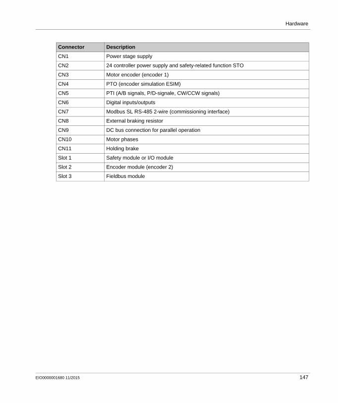
Hardware
Connector Description
CN1 Power stage supply
CN2 24 controller power supply and safety-related function STO
CN3 Motor encoder (encoder 1)
CN4 PTO (encoder simulation ESIM)
CN5 PTI (A/B signals, P/D-signale, CW/CCW signals)
CN6 Digital inputs/outputs
CN7 Modbus SL RS-485 2-wire (commissioning interface)
CN8 External braking resistor
CN9 DC bus connection for parallel operation
CN10 Motor phases
CN11 Holding brake
Slot 1 Safety module or I/O module
Slot 2 Encoder module (encoder 2)
Slot 3 Fieldbus module
EIO0000001680 11/2015 147

Hardware
Wiring
The wiring example shows the basic wiring of the Lexium 32M servo drive. Thanks to the flexibility of the Lexium 32M servo drive the device can be adapted to a wide variety of tasks with numerous modules. See the product manuals of the modules for details on wiring.
1 Emergency stop2 Commissioning accessories
148 EIO0000001680 11/2015

Hardware
Lexium BSH/BMH Servo Motors - Hardware
Front View
Lexium BSH/BMH servo motors
Description
The Lexium BSH/BMH servo motor movements are controlled by Lexium 32 servo drives.
BSH servo motors are the ideal choice to meet requirements for dynamics and precision. With 4 flange sizes and various lengths, there is a suitable solution for most applications, covering a continuous stall torque range from 0.5 Nm to 33.4 Nm for speeds up to 9000 rpm.
BMH servo motors provide unequaled power density values to meet the requirements of most compact machines. With 5 flange sizes and 3 different lengths for each flange size, they are suitable for most applications, covering a continuous stall range from 1.2 Nm to 84 Nm for speeds up to 8000 rpm. With their medium inertia motor, the BMH servo motors are ideal for high-load applications and enable more robust adjustment of the movement, making for easier installation and adjustment.
BSH and BMH servo motors are certified as "Recognized" by the UL (underwriters laboratories) and conform to UL 1004 standards as well as to European directives (CE marking).
They are available with the following variants: 4 (BSH) and 5 (BMH) flange sizes (mm): 55, 70, 100, 140 and 205 (BMH) 2 degrees of protection for the shaft end: IP 50 or IP 65 in accordance with standard IEC/EN
60529The degree of protection of the casing is IP 65 (IP 67 with the conformity kit, which is available as an option).
With or without holding brake Straight or angled connectors for power and encoder connection Integrated SinCos Hiperface single turn or multiturn encoder (medium or high resolution) Untapped or keyed shaft end
EIO0000001680 11/2015 149

Hardware
BSH and BMH servo motors have been developed to comply with the following main specifications: The ambient operating temperature is –20...+ 40 °C (–4...+ 104 °F) without derating, in
accordance with standard IEC 60721-3-3, category 3K3 and up to 55 °C (131 °F) with derating of 1% of the nominal output power per additional 1 °C (1.8 °F) above 40 °C (104 °F).
The maximum operating altitude is 1000 m (3281 ft) without derating, 2000 m (6562 ft) with k = 0.86 and 3000 m (9843 m) with k = 0.8.
The relative humidity that the servo motor can withstand is in line with standard IEC 60721-3-3, categories 3K3, 3Z12 and 3Z2.
The windings are insulation class F (maximum temperature for windings 155 °C/311 °F) in accordance with standard IEC 60034-1.
All mounting positions are permitted (horizontal mounting (IMB5) or vertical mounting (IMV1 with shaft end at the top and IMV3 with shaft end at the bottom) in accordance with standard IEC 60034-7.
For more information, refer to : BMH, Servo motor, Motor manual, 0198441113749 (ENG) BSH, Servo motor, Motor manual, 0198441113837 (ENG)
Wiring
Schneider Electric provides a wide range of preformed cables for motor and encoder connections between the servo motor and the Lexium 32 drive. An overview about the offer is provided in the appropriate catalog and in the product manual of the Lexium BSH respectively BMH servo motors.
150 EIO0000001680 11/2015

Hardware
Detection
Section 4.7Detection
What Is in This Section?
This section contains the following topics:
Topic Page
OsiSense XGCS850 RFID - Hardware 152
OsiSense Industrial Sensors - Hardware 155
EIO0000001680 11/2015 151

Hardware
OsiSense XGCS850 RFID - Hardware
Front View
OsiSense XGC850
Description
The OsiSense XG Ethernet smart antenna combines a compact design and remarkable features to provide elevated performances in read/write operations on 13.56 MHz RFID tags, and flexibility in network connectivity supporting both Ethernet IP and Modbus TCP/IP networks.
The smart antenna is a compact RFID station offering the following advantages: 2 Ethernet ports An embedded Web server allowing: Setup Diagnostic Monitoring
Daisy chaining up to 32 smart antennas Compatible with most 13.56 MHz tags on the market
Embedded functions are activated by standard requests to read/write words, sent by the PLC: Reset: The RFID part of the smart antenna is reinitialized and assumes its factory default
configuration. Init: The smart antenna is reinitialized and operates as it would after being switched back on
(address unchanged, RFID parameters deleted). Sleep mode: Transmission of the electromagnetic field of the smart antenna is only activated
upon receipt of a read or write instruction. This mode reduces the power consumption of the smart antenna and prevents interference when the smart antennas are in close proximity to each other.
Auto read/write: This mode enables the smart antenna to execute up to 10 read or write instructions on a tag automatically (without PLC command) as soon as the RFID tag enters the dialogue zone.
152 EIO0000001680 11/2015

Hardware
For more information, refer to RFID OsiSense XG, Ethernet Smart Antenna, User Manual, EIO0000001601.
Physical Overview
Standards and certifications UL508, CE, EN 300330, EN 301489-01/03
Power supply 24 Vdc PELV, connection on M8 4 pins male socket
Power consumption < 150 mA
Nominal range 20...100 mm (0.78...3.94 in) depending on associated tag
Type of associated tag Standardized ISO 15693 and ISO 14443 tags, automatic detection of the tag type
RFID frequency 13.56 MHz
Communication Interface: Ethernet dual port 10 BASE-T/100 BASE-TXConnection: 2x M12 D coded female sockets for chaining
Temperature Operation: -25...+70 °C (-13...+158 °F)Storage: -40...+85 °C (-13...+158 °F)
Degree of protection IP 65 according to IEC 60529
Dimensions W x H x D: 80 x 93 x 40 mm (3.15 x 3.66 x 1.57 in.)
1 TAG: Tag LED 6 M8 socket, 24 Vdc power supply
2 COM: Communication LED 7 M12 socket, Ethernet port 2
3 NS: Network status LED 8 LK/SP: Ethernet communication port 2 LED
4 LK/SP: Ethernet communication port 1 LED 9 MS: Ethernet module status LED
5 M12 socket, Ethernet port 1 - -
EIO0000001680 11/2015 153

Hardware
Installation Example
Example of an Ethernet TCP/IP network setup with smart antennas
1 PLC 5 Ethernet cable XGSZ12E12••
2 Ethernet switch 6 Power supply cable XZCP0941L•
3 Smart antenna 7 M12 connector cap ASI67FACC1 (2 caps are supplied with the smart antenna)
4 Ethernet cable XGSZ12E45•• - -
154 EIO0000001680 11/2015

Hardware
OsiSense Industrial Sensors - Hardware
Front View
OsiSense industrial sensors product range
Description
Under the Telemecanique Sensors brand, the latest innovations in the field of sensors for industrial detection operations are offered.
The OsiSense product range consists of safety and limit switches, pressure control sensors, ultrasonic sensors, inductive and capacitive proximity sensors, and so on.
For more information, refer to Detection for automation solutions OsiSense, MKTED210041EN.
EIO0000001680 11/2015 155

Hardware
156 EIO0000001680 11/2015

Distributed Modbus TCP Logic Controller M251
Communication and Wiring
EIO0000001680 11/2015
Communication Topology and Wiring Guide
Chapter 5Communication Topology and Wiring Guide
What Is in This Chapter?
This chapter contains the following sections:
Section Topic Page
5.1 Introduction to System Communication 158
5.2 Ethernet Network 159
5.3 Modbus Serial Line Network 183
EIO0000001680 11/2015 157

Communication and Wiring
Introduction to System Communication
Section 5.1Introduction to System Communication
Introduction
Overview
The TVDA (Tested Validated Documented Architecture) includes three different communication networks. Ethernet 1
The Ethernet 1 interface of the M251 controller is equipped with an embedded 2-port Ethernet switch and is used to connect the controller to a LAN (Local Area Network).
Ethernet 2The Ethernet 2 interface of the M251 controller is used to connect the controller to the device network of the architecture. The device network links the devices with Ethernet connectivity in the architecture. The network structure combines star and daisy-chain topology. The Ethernet network is the physical layer for the communication protocols used in this architecture. The SoMachine network protocol is used for the communication between the controller and the 2 Magelis touch panels HMI GTO. The Modbus TCP protocol is used as fieldbus in the architecture and the Modicon M251 Logic Controller is defined as Modbus TCP master. The Altivar 32 drives, Lexium 32 drives, Harmony wireless access point, Advantys ETB, encoder, OsiSense XG, and the Modicon OTB are Modbus TCP slaves.
Modbus SLThe Modbus SL RS-485 2-wire network is used for the communication between the Modicon M251 Logic Controller (master) and the energy meter iEM3150 (slave).
158 EIO0000001680 11/2015

Communication and Wiring
Ethernet Network
Section 5.2Ethernet Network
What Is in This Section?
This section contains the following topics:
Topic Page
Network Planning and Installation 160
Ethernet Network Topology 163
Ethernet Wiring 164
Modicon M251 Logic Controller - Ethernet Wiring 167
Altivar 32 Variable Speed Drive - Ethernet Wiring 169
Lexium 32M Servo Drive - Ethernet Wiring 171
Magelis HMI GTO5310 - Ethernet Wiring 173
OsiSense XGCS850 RFID - Ethernet Wiring 174
Advantys ETB - Ethernet Wiring 175
Modicon OTB - Ethernet Wiring 177
Absolute Encoder - Ethernet Wiring 180
Harmony ZBRN1 Access Point - Ethernet Wiring 182
EIO0000001680 11/2015 159

Communication and Wiring
Network Planning and Installation
Overview
The controller TM251MESE is equipped with two independent Ethernet interfaces. This allows you to link the controller to two different networks. Usually, the Ethernet 1 interface is used to link the controller to the control network, such as a manufacturing execution system. The Ethernet 2 interface of the controller is dedicated for the device network of the architecture.
In contrast to Ethernet 1 interface, the Ethernet 2 interface supports additional features like Modbus TCP IOScanner, EtherNet/IP IOScanner, and DHCP Server, which are tools for the realization of an industrial Ethernet network at the machine level; that is, as a fieldbus network. These features are contained within the Industrial Ethernet Manager in the Devices tree in SoMachine.
For more information, refer to : Modicon M251 Logic Controller, Programming Guide, EIO0000001462. SoMachine Industrial EtherNet, User Guide, EIO0000002215
Transparency
The controller TM251MESE supports IP Forwarding between the Ethernet 1 network and the Ethernet 2 network. Therefore a PC connected to the Ethernet 1 network is able to access to the devices linked to the Ethernet 2 network.
A precondition for IP Forwarding is that the PC has the correct IP routes defined. For example, you can set the gateway in the Ethernet settings of the PC to those defined for the Ethernet 1 interface. In addition, the devices on the Ethernet 2 network must use the IP address of the Ethernet 2 interface of the target controller as gateway address.
Security Parameters
The controller TM251MESE supports numerous features related to the cyber security. The different protocols supported by the controller can be enabled or disabled in the Ethernet configuration.
In addition, a configurable firewall can be activated for the controller. The firewall helps to protect the controller on the network by blocking unauthorized access while permitting authorized access. The firewall is configured via a script file. The script file can be stored on the controller or on the SD card of the controller.
160 EIO0000001680 11/2015

Communication and Wiring
Network Planning
Define Ethernet 1 network
In this architecture, the Ethernet 1 interface is used to link the controller to the control network. The Ethernet setting for the Ethernet 1 interface of the controller are defined by the administrator of the control network.
Define Ethernet 2 network
The Ethernet 2 network is an independent, local network and has only few nodes.
Essential steps for the planning of the device network: Define the IP address of the controller. Decide whether to use static or served IP addresses for the devices. Define the IP addresses of the devices. Define the number and type of switches to be used, taking into account the capability of daisy
chaining on some devices. Define for each device the repetition rate (Modbus TCP) and the RPI (CIP connection)
according to your needs and in order to optimize the band width of the network.
NOTE: Each daisy chain link introduces 20 µs delay of the frames.
Test Installation and IP Address Assignment
After installation and configuration, verify your installation: Verify the correct installation of the network. Verify the Ethernet state LEDs on all network devices. Connect a PC with a compatible IP address to the network and verify the IP addresses for each
device using a ping service. (Remote ping service is available on the Web server of the M251 controller).
Carefully manage the IP addresses because each device on the network requires a unique address. Having multiple devices with the same IP address can cause unintended operation of your network and associated equipment.
WARNINGUNINTENDED EQUIPMENT OPERATION
Verify that there is only one master controller configured on the network or remote link. Verify that all devices have unique addresses. Obtain your IP address from your system administrator. Confirm that the IP address of the device is unique before placing the system into service. Do not assign the same IP address to any other equipment on the network. Update the IP address after cloning any application that includes Ethernet communications to
a unique address.
Failure to follow these instructions can result in death, serious injury, or equipment damage.
EIO0000001680 11/2015 161

Communication and Wiring
NOTE: Verify that your system administrator maintains a record of all assigned IP addresses on the network and subnetwork, and inform the system administrator of all configuration changes performed.
162 EIO0000001680 11/2015

Communication and Wiring
Ethernet Network Topology
Ethernet Topology
#... IP address starts with 172.21.2.A Ethernet 1 interface - linked to the control network B Ethernet 2 interface - fieldbus architecture and HMI communication
The subnet mask for Ethernet 1 is 255.255.255.0.
The subnet mask for Ethernet 2 is 255.255.255.0.
Optionally a PC with compatible Ethernet settings can be linked to the Ethernet 2 network for commissioning and monitoring.
Thanks to the capability of the IP Forwarding on the M251 controller, you also have access to Ethernet 2 network from a PC which is linked to Ethernet 1 network (refer to Transparency (see page 160)).
EIO0000001680 11/2015 163

Communication and Wiring
Ethernet Wiring
Overview Ethernet
A Ethernet 1 interface - linked to the control networkB Ethernet 2 interface - fieldbus architecture and HMI communication
For more information, refer to Transparent Ready, User Guide, 31006929.
164 EIO0000001680 11/2015

Communication and Wiring
Wiring Accessories
Switches
Position Reference Designation Description Cable length
1 VW3E3001R005 Ethernet patch cable - shielded twisted-pair straight cord
One RJ45 connector at each end 0.5 m (1.64 ft)
VW3E3001R010 1.0 m (3.28 ft)
VW3E3001R020 2.0 m (6.56 ft)
VW3E3001R030 3.0 m (9.84 ft)
3 TCSEAAF11F13F00 ConneXium M12 to RJ45 Ethernet adapter
Adapter for panel mounting -
4 TCSECL1M1M1S2 Ethernet patch cable - shielded twisted-pair straight cord
One IP 67, M12, 4-pin (D-coded) connector at each end
1.0 m (3.28 ft)
TCSECL1M1M3S2 3.0 m (9.84 ft)
TCSECL1M1M10S2 10.0 m (32.8 ft)
TCSECL1M1M25S2 25.0 m (82 ft)
TCSECL1M1M40S2 40.0 m (131.2 ft)
6 TCSECL1M3M3S2 Ethernet patch cable - shielded twisted-pair straight cord
One IP 67, M12, 4-pin (D-coded) connector and one RJ45 connector
3.0 m (9.84 ft)
Position Reference Designation Description
2 TCSESM083F23F0 ConneXium Ethernet TCP/IP managed switch
8 x 10/100BASE-TX ports (copper cable), RJ45 shielded connectors
5 TCSESU051F0 ConneXium Ethernet TCP/IP unmanaged switch
5 x 10BASE-T/100BASE-TX ports (copper cable), shielded M12 type D connectors, IP 67
7 TCSESU053FN0 ConneXium Ethernet TCP/IP unmanaged switch
5x 10BASE-T/100BASE-TX ports (copper cable), RJ45 shielded connectors
EIO0000001680 11/2015 165

Communication and Wiring
ConneXium Ethernet Adapter
TCSEAAF11F13F00
ConneXium Ethernet Cable
TCSECL1M1MxxS2
TCSECL1M3MxxS2
M12 connector (D-Coded)
M12 pin Signal Description RJ45 pin RJ45 connector
1 TD+ Transmit data + 1
2 RD+ Received data + 3
3 TD- Transmit data - 2
4 RD- Received data - 6
- - Not connected 4
- - Not connected 5
- - Not connected 7
- - Not connected 8
166 EIO0000001680 11/2015

Communication and Wiring
Modicon M251 Logic Controller - Ethernet Wiring
Ethernet Interfaces TM251MESE
Characteristic Description
Standard Ethernet
Connector type Ethernet 1: Embedded dual port RJ45 Ethernet switch Ethernet 2: RJ45
Bit rate Supports Ethernet "10BaseT" and "100BaseTX" with auto-negotiation
Automatic cross-over MDI / MDIX
Services supported Ethernet 1 and Ethernet 2: Modbus TCP client/server EtherNet/IP device FTP server Web server SNMP Modbus TCP slave device IEC VAR ACCESS
For Ethernet 2 only: Modbus TCP IOScanner EtherNet/IP originator DHCP server Fast Device Replacement (FDR) server
EIO0000001680 11/2015 167

Communication and Wiring
For more information, refer to Modicon M251 Logic Controller, Hardware Guide, EIO0000001486.
Pin Assignment
RJ45 Ethernet connector
NOTE: The controller supports the MDI/MDIX auto-crossover cable function. It is not necessary to use special Ethernet crossover cables to connect devices directly to this port (connections without an Ethernet hub or switch).
IP address negotiation type supported
DHCP BOOTP Fixed IP
Power over Ethernet No
Characteristic Description
RJ45 pin Signal Description
1 TD+ Transmit data +
2 TD- transmit data -
3 RD+ Received data +
4 - No connection
5 - No connection
6 RD- Received data -
7 - No connection
8 - No connection
168 EIO0000001680 11/2015

Communication and Wiring
Altivar 32 Variable Speed Drive - Ethernet Wiring
Overview
For the operation via Modbus TCP or EtherNet/IP, the Altivar 32 has been equipped with the dual port Ethernet communication module VW3 A3616.
In addition to the communication services provided by each protocol, the VW3 A3616 provides a set of common services at the Ethernet and TCP/IP level.
The VW3 A3616 also provides an embedded web server which offers monitoring and commissioning functions directly from a web browser.
Altivar 32 with dual port Ethernet communication module (VW3 A3616)
VW3 A3616 option cards, with 1.2IE01 or greater version of firmware, are compliant with Altivar 32.
NOTE: Verify the firmware version on the packaging label (on the right part of the label).
For more information, refer to Altivar 32 Variable speed drives for synchronous and asynchronous motors, Modbus TCP - EtherNet/IP, Communication Manual, S1A28701.
EIO0000001680 11/2015 169
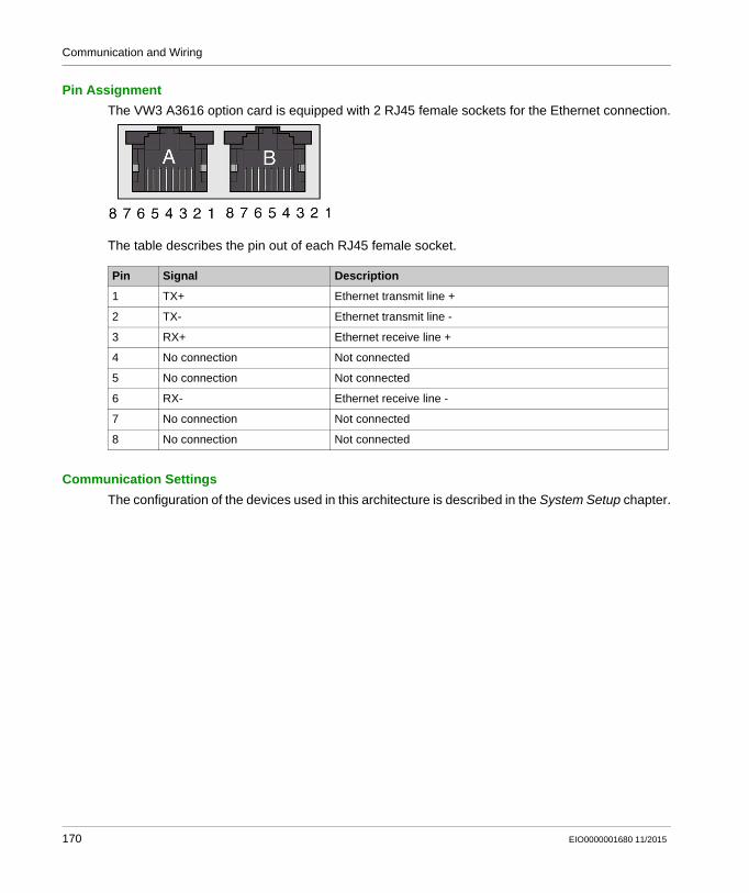
Communication and Wiring
Pin Assignment
The VW3 A3616 option card is equipped with 2 RJ45 female sockets for the Ethernet connection.
The table describes the pin out of each RJ45 female socket.
Communication Settings
The configuration of the devices used in this architecture is described in the System Setup chapter.
Pin Signal Description
1 TX+ Ethernet transmit line +
2 TX- Ethernet transmit line -
3 RX+ Ethernet receive line +
4 No connection Not connected
5 No connection Not connected
6 RX- Ethernet receive line -
7 No connection Not connected
8 No connection Not connected
170 EIO0000001680 11/2015

Communication and Wiring
Lexium 32M Servo Drive - Ethernet Wiring
Overview
For the operation via Modbus TCP or EtherNet/IP, the Lexium 32M has been equipped with the dual port Ethernet communication module VW3 A3616.
In addition to the communication services provided by each protocol, the VW3 A3616 provides a set of common services at the Ethernet and TCP/IP level.
The VW3 A3616 also provides an embedded web server which offers monitoring and commissioning functions directly from a web browser.
Lexium 32M with dual port Ethernet communication module (VW3 A3616)
For more information, refer to LXM32M, Modbus-TCP module, Fieldbus manual, 0198441113843.
EIO0000001680 11/2015 171

Communication and Wiring
Pin Assignment
The VW3 A3616 option card is equipped with 2 RJ45 female sockets for the Ethernet connection.
The table describes the pin out of each RJ45 female socket.
Communication Settings
The configuration of the devices used in this architecture is described in the System Setup chapter.
Pin Signal Description
1 TX+ Ethernet transmit line +
2 TX- Ethernet transmit line -
3 RX+ Ethernet receive line +
4 No connection Not connected
5 No connection Not connected
6 RX- Ethernet receive line -
7 No connection Not connected
8 No connection Not connected
172 EIO0000001680 11/2015

Communication and Wiring
Magelis HMI GTO5310 - Ethernet Wiring
Ethernet Port
The Ethernet connection is used for the communication between the controller and the HMI. The Magelis panel HMI GTO provides an RJ45 port for Ethernet TCP/IP link, 10BASE-T/100BASE-TX with an activity LED to communicate with the controller and the PC.
1 RJ45 connector
EIO0000001680 11/2015 173

Communication and Wiring
OsiSense XGCS850 RFID - Ethernet Wiring
Overview
The OsiSense XG smart antenna is equipped with a built-in unmanaged 2-port Ethernet switch comprising two female 4-pin D-coded M12 connectors. This allows you to use the network topology that meets your application needs.
These topologies include the following: Star Daisy-chain Ring (daisy-chain with loopback) Combination of star and daisy-chain
For more information, refer to RFID OsiSense XG, Ethernet Smart Antenna, User Manual, EIO0000001601.
Pin Assignment
The figure shows the pin assignments of the two Ethernet network connectors on the module.
Address Settings
In this architecture, the module is configured with a static IP address.
The configuration of the IP address is done by setting parameters in the web server embedded in the smart antenna.
The configuration of the device used in this architecture is described in the System Setup chapter.
Pin Signal Description
1 TX+ Ethernet transmit line +
2 RX+ Ethernet receive line +
3 TX- Ethernet transmit line -
4 RX- Ethernet receive line -
174 EIO0000001680 11/2015
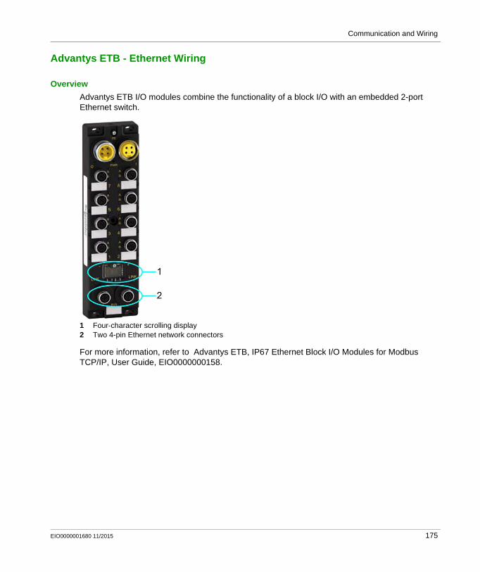
Communication and Wiring
Advantys ETB - Ethernet Wiring
Overview
Advantys ETB I/O modules combine the functionality of a block I/O with an embedded 2-port Ethernet switch.
1 Four-character scrolling display2 Two 4-pin Ethernet network connectors
For more information, refer to Advantys ETB, IP67 Ethernet Block I/O Modules for Modbus TCP/IP, User Guide, EIO0000000158.
EIO0000001680 11/2015 175

Communication and Wiring
Pin Assignment
The figure shows the pin assignments of the two Ethernet network connectors on the module.
Address Settings
In this architecture, the module is configured with a static IP address.
The configuration of the IP address is done by setting parameters in the Web server embedded in the smart antenna.
The configuration of the device used in this architecture is described in the System Setup chapter (see page 237).
Pin Signal Description
1 TX+ Ethernet transmit line +
2 RX+ Ethernet receive line +
3 TX- Ethernet transmit line -
4 RX- Ethernet receive line -
176 EIO0000001680 11/2015

Communication and Wiring
Modicon OTB - Ethernet Wiring
Overview
For more information, refer to Advantys OTB Ethernet, Remote Inputs/Outputs, User Manual, 1606385.
1 Two encoder wheels are used to define the IP address assignment mode.
2 Terminal for the 24 Vdc supply of the network interface module.
3 An RJ45 connector is used to connect the Modicon OTB module to an Ethernet network.
4 Visual information on the operational state of the network interface module.
EIO0000001680 11/2015 177

Communication and Wiring
Pin Assignment
The Ethernet connector is located on the bottom side of the network interface module.
Pin Signal Description
1 TX+ Ethernet transmit line +
2 TX- Ethernet transmit line +
3 RX+ Ethernet receive line +
4 - -
5 - -
6 RX- Ethernet receive line -
7 - -
8 - -
178 EIO0000001680 11/2015

Communication and Wiring
Address Settings
Two encoder wheels on the OTB 1E0DM9LP Modicon OTB are used to define the IP address assignment mode.
There are 3 different ways to assign the Modicon OTB island IP address: Address assignment by a DHCP (Dynamic Host Control Protocol) server Address assignment by a BOOTP (Bootstrap Protocol) server (BOOTP zone on right encoder
wheel) IP address stored in the flash memory (stored zone on right encoder wheel)
NOTE: If the above addressing modes are unsuccessful, the OTB starts on a default IP address derived from the MAC address.
NOTE: The Modicon OTB module detects if a duplicate address is present. It will not start up until it has been rectified.
In this architecture, the address assignment by a DHCP server is selected. The DHCP server is configured on the Modicon M251 Logic Controller. The Modicon OTB is identified by the device name OTB105. The device name is set using the two encoder wheels on the front of the OTB.
Step Action Comment
1 Set the encoder wheels to the value 10 and 5: Left thumbwheel = 10 (tens) Right thumbwheel = 5 (ones)
This action defines the name of the Modicon OTB module OTBXXY which is used by the DHCP server. XXY corresponds to the value coded on the encoder wheels.
2 Wait for 10 s. When the position has been stable for 10 s, the OTB module triggers a request for an IP address.
EIO0000001680 11/2015 179

Communication and Wiring
Absolute Encoder - Ethernet Wiring
Overview
The encoder of type MHM5-EM00B-1213-C100-PRM from BEISensors is equipped with one 4-pin D-coded M12 connector for the Ethernet connection.
For more information, refer to the associated user manual for absolute rotary encoders with Modbus TCP interface provided by BEISensors.
Pin Assignment
The figure shows the pin assignments of the Ethernet network connectors on the encoder.
Address Settings
Pin Signal Description
1 TX+ Ethernet transmit line +
2 RX+ Ethernet receive line +
3 TX- Ethernet transmit line -
4 RX- Ethernet receive line -
1 Switch 2 - selection for source of the IP address
2 Switch 1 - not in use
3 Two hex rotary switches - not in use
180 EIO0000001680 11/2015

Communication and Wiring
The rotary encoder can be used either with the wired IP 10.10.10.10 or the software IP address which can be programmed.
A switch to choose either option is located in the connection cap. If the switch 2 is in position "off", the programmable IP has been chosen. Both hex rotary switches and switch 1 are not in use for this encoder.
In this architecture, the encoder is configured with a static IP address.
The configuration of the device used in this architecture is described in the System Setup chapter (see page 245).
EIO0000001680 11/2015 181

Communication and Wiring
Harmony ZBRN1 Access Point - Ethernet Wiring
Ethernet Port
The Ethernet connection is used to exchange data between several devices connected together on a network.
The ZBRN1 access point is equipped with a plugged-in ZBRCETH communication module which provides 2 RJ45 plugs.
The communication module supports the Ethernet Modbus/TCP protocol.
It enables daisy chain wiring between devices without using a switch.
1 ZBRN1 access point2 ZBRCETH communication module with 2 RJ45 plugs
182 EIO0000001680 11/2015

Communication and Wiring
Modbus Serial Line Network
Section 5.3Modbus Serial Line Network
What Is in This Section?
This section contains the following topics:
Topic Page
Modbus SL Network Topology 184
Modbus SL Wiring 185
Modicon M251 Logic Controller - Modbus SL Wiring 186
iEM31xx Energy Meter - Modbus SL Wiring 188
EIO0000001680 11/2015 183

Communication and Wiring
Modbus SL Network Topology
Modbus SL Topology
#... Slave address
184 EIO0000001680 11/2015

Communication and Wiring
Modbus SL Wiring
Modbus SL Overview
For more information, refer to Modbus Serial Line, Planning and Installation Guide, 33003925.
Cable
Reference Designation Description Position Cable length
VW3A8306D30 Modbus SL drop cable 1 RJ45 connector and one end stripped
1 3.0 m (9.8 ft)
EIO0000001680 11/2015 185

Communication and Wiring
Modicon M251 Logic Controller - Modbus SL Wiring
Modbus SL Port (Serial Line)
The serial line is used to communicate with devices supporting the Modbus protocol as either master or slave,
ASCII protocol (printer, modem...), and SoMachine protocol (HMI,...) provides a 5 Vdc power distribution
For more information, refer to Modicon M251 Logic Controller, Hardware Guide, EIO0000001486.
186 EIO0000001680 11/2015

Communication and Wiring
Pin Assignment
For this architecture, the port is configured as an RS-485.
Pins for RS-485 and RS-232
Communication Settings
The Modbus SL port of the controller has to be configured within SoMachine. Baud rate: 19.2 kbps Parity: even Stop bit: 1 Physical medium: Modbus SL RS-485 2-wire
Line Polarization
Line polarization is provided by the controller.
Pin Signal RS-485 Signal RS-232 Description
1 - RxD RS-232: Receive data line
2 - TxD RS-232: Transmit data line
3 - - -
4 D1 - Modbus SL: D1 (+/B) RS-485 2-wire
5 D0 - Modbus SL: D0 (-/A) RS-485 2-wire
6 - - -
7 VP5S - Power over Modbus SL: 5 V / max. 200 mA supply
8 SNG Common Modbus SL signal ground / reference to VP5S
WARNINGUNINTENDED EQUIPMENT OPERATION
Do not connect wires to unused terminals and/or terminals indicated as “No Connection (N.C.)”.
Failure to follow these instructions can result in death, serious injury, or equipment damage.
EIO0000001680 11/2015 187

Communication and Wiring
iEM31xx Energy Meter - Modbus SL Wiring
Modbus SL Port
1 Modbus SL RS-485 2-wire port
For more information, refer to iEM3100 series / iEM3200 series, Energy Meters, User Manual, DOCA0005EN.
188 EIO0000001680 11/2015

Communication and Wiring
Pin Assignment
Communication Settings
The Modbus SL port of the energy meter has to be configured via the local HMI on the front.
Item Signal Description
1 SNG Modbus SL signal ground
2 D0 Modbus SL: D0 (-/A) RS-485 2-wire
3 D1 Modbus SL: D1 (+/B) RS-485 2-wire
4 SHLD Modbus SL shield
EIO0000001680 11/2015 189

Communication and Wiring
190 EIO0000001680 11/2015

Distributed Modbus TCP Logic Controller M251
Implementation
EIO0000001680 11/2015
Implementation
Chapter 6Implementation
What Is in This Chapter?
This chapter contains the following sections:
Section Topic Page
6.1 Software Requirements 192
6.2 Access the SoMachine Project Template 193
6.3 Project 194
EIO0000001680 11/2015 191

Implementation
Software Requirements
Section 6.1Software Requirements
Software Requirements
Overview
The software required to open and to edit the project template is SoMachine 4.1 SP2 or later.
NOTE: The SoMachine 4.1 SP2 software is an update package and requires a previously installed SoMachine 4.1 SP1 on your PC.
The following components must be installed together with SoMachine: SoMachine components SoMachine Logic Builder Vijeo-Designer Gateway
Auxiliary tools Controller assistant
Controllers M251 MESE EIP
Devices Advantys (DTM) Altivar (DTM) Harmony (DTM) Lexium (DTM)
Repository Optimized repository
Documentation Tested, Validated and Documented Architecture
The SoMachine Configuration Manager, which is part of the SoMachine installation, allows you to verify the installation on your PC. In addition you can add, remove, or update components of your SoMachine installation.
192 EIO0000001680 11/2015

Implementation
Access the SoMachine Project Template
Section 6.2Access the SoMachine Project Template
Access the SoMachine Project Template
Overview
The SoMachine project related to the described architecture is available in terms of a project template.
It is tested and validated and includes the complete and executable application with program code and device configurations.
Also part of the SoMachine project is the Vijeo-Designer application which is ready to run on the defined Magelis panel for this architecture.
You can use the project template as basis for your own application.
Procedure
You can access the project template as described below.
Step Action
1 Launch SoMachine.The Get started dialog box of SoMachine Central is displayed.
2 Click New.The New Project dialog box is displayed.
3 Click Templates.The New Project Assistant - Templates dialog box is displayed.
4 Enter a Project Name of your choosing.
5 Select a template from the list. The template that you choose will have the same name as the title of the present document.
6 Click the Create Project button.A new project based on the selected template is opened in SoMachine Logic Builder.
7 Now you can adapt (see page 252) your new project according to your requirements.
EIO0000001680 11/2015 193

Implementation
Project
Section 6.3Project
What Is in This Section?
This section contains the following topics:
Topic Page
Controller 195
HMI 198
Devices 200
Application 209
Vijeo-Designer 211
194 EIO0000001680 11/2015

Implementation
Controller
Overview
The controller in this architecture is the TM251MESE. The mandatory settings for the controller are described below. The parameter values depicted in this document relate to the template project and the test equipment used during development.
For more information about the Ethernet settings, refer to the document Modicon M251 Logic Controller, Programming Guide, EIO0000001462.
Ethernet 1
The Ethernet 1 network in this architecture is used to connect the controller to a LAN (Local Area Network), for example the control network.
The Ethernet settings for the Ethernet 1 interface in this architecture are: Fixed IP address IP address: 10.128.153.131 Subnet mask: 255.255.255.0
The default settings for the network security parameters have been retained (all services and protocols enabled). You need to decide, according to your network security needs, which services and protocols must be disabled.
Ethernet 2
The Ethernet 2 network on the M251 controller is defined for the device network. The Ethernet devices of this architecture like HMIs, drives, sensors, and I/O devices are linked to the Ethernet 2 network.
The Ethernet settings for the Ethernet 2 interface in this architecture are: Fixed IP address IP address: 172.21.2.1 Subnet mask: 255.255.255.0
The default settings for the network security parameters have been retained (all services and protocols enabled). You need to decide, according to your network security needs, which services and protocols must be disabled.
The Ethernet 2 interface supports a DHCP server. By the corresponding check box in the device editor of the Ethernet 2 interface, the DHCP server can be disabled. In this application, the DHCP server is enabled because some of the slave devices are configured in this mode. If the DHCP server is enabled, the use of fixed IP addresses is not suppressed, but if so, each device that is added under the Ethernet Network Manager in the Devices tree has the DHCP mode enabled by default.
EIO0000001680 11/2015 195

Implementation
Industrial Ethernet manager
The DHCP server and the fieldbus communication with the slave devices in the device network is managed through the Industrial Ethernet manager. Therefore it is added under the Ethernet 2 interface of the controller in the Devices tree.
Scanner Settings
On the tab Scanner Settings, various parameters can be adjusted.
The preferred protocol in this architecture is Modbus TCP. The preferred protocol parameter determines the type of protocol used for a device when added to the fieldbus using the drag-and-drop function from the catalog.
The timeout for the explicit messaging is set to 3 s for connected messages and 10 s for unconnected messages.
Network Manager
On the tab Network Manager, the network devices configured in the device network are listed. This is a central place to manage the IP configuration of the devices. Although this is the central place to manage IP configuration, you can also modify IP configuration information in the Device Editor of the device. The settings on the devices are updated with the settings which were modified in the Network Manager and conversely with the Device Editor.
Scanner Resources
On the tab Scanner Resources, the resources used by the configuration are summarized. Based on the resources used, the total load for the Industrial Ethernet manager can be calculated. The values for this application are listed below:
EtherNet/IP scanner resources Number of connections configured: 0/16 Input words: 0/1024 Output words: 0/1024
Modbus TCP scanner resources Number of channels configured: 12/64 Input words: 119/2048 Output words: 44/2048 Industrial Ethernet scanner load: 33%
196 EIO0000001680 11/2015

Implementation
Serial Line
The serial line in this architecture is used for the communication between the controller and the energy meter. Therefore, a Modbus manager has been added, via the template you used to create the application, under the serial line interface of the controller.
The serial line settings for this architecture are: Baud rate: 19200 Parity: even Data bits: 8 Stop bits: 1 Physical medium: Modbus SL RS-485 2-wire Polarization resistor: No
The configuration of the Modbus manager is: Transmission mode: RTU Addressing: Master Time between frames: 10 ms
EIO0000001680 11/2015 197

Implementation
HMI
Overview
In this architecture, there are two different HMIs (HMI GTO 5310 and HMI GTO 4310). The mandatory settings for the HMI devices are described below. The parameter values depicted in this document relate to the template project and the test equipment used during development.
Ethernet
The communication between the HMIs and the controller is realized via an Ethernet connection using the SoMachine network protocol. Therefore, the HMIs are also linked to the device network of the system but, in contrast to the other slave devices, the HMIs are not configured on the controller.
The Ethernet settings for the panel HMI GTO 4310 are: Fixed IP address IP address: 172.21.2.10 Subnet mask: 255.255.255.0 Gateway address: 172.21.2.1
For the other parameters, the default settings have been kept.
The Ethernet settings for the panel HMI GTO 5310 are: Fixed IP address IP address: 172.21.2.30 Subnet mask: 255.255.255.0 Gateway address: 172.21.2.1
For the other parameters, the default settings have been kept.
198 EIO0000001680 11/2015

Implementation
I/O Manager
The communication between HMI and controller is realized via SoMachine network protocol based on Ethernet.
The SoMachine network driver on the panel accesses variables in the controller by a defined reference. Therefore, the node name (equipment address) of the connected controller must be set in the SoMachine network configuration dialog in Vijeo-Designer.
The node name of the controller is per default a combination of controller type and MAC address, you can change it to a user-defined name (for example: machine 1).
In this application, the default node name of the controller has been set within the Vijeo-Designer configuration.
Usually the node name of the controller is added automatically to configuration in Vijeo-Designer once the controller has been selected in the Controller Selection tab in SoMachine. If not, or if the node name has been modified, the node name can be obtained in the Controller Selection tab in SoMachine and must be added manually in Vijeo-Designer.
For more information about the SoMachine network driver, refer to the document Magelis XBT GC/XBT GK/XBTGT, SoMachine - Combo and Network Drivers, EIO00000000219 (ENG).
EIO0000001680 11/2015 199

Implementation
Devices
Overview
In this chapter, the devices configured within the SoMachine project are described.
TM3 Safety Modules
The TM3 safety modules are configured as I/O expansion modules and must be connected to the TM3 bus of the controller. Diagnostic and administrative control functions are provided over the TM3 bus while the safety-related function is managed in the module. The diagnostic and control signals are treated as I/O in the controller configuration, and can be processed in the application program as such. To add a TM3 safety module to the configuration, select the command Add Device from the context menu of the IO_Bus node in the Devices tree. In the Add Device dialog box, double-click the desired device.
In this architecture, the following module was added to the TM3 IO_Bus.
For more information, refer to Modicon TM3 Safety Modules, Hardware Guide, EIO0000001831.
TM3 I/O Expansion Modules
The controller provides the possibility to expand the embedded I/Os by adding TM3 expansion modules to the controller.
To add a TM3 module to the configuration, select the command Add Device from the context menu of the IO_Bus node in the Devices tree. In the Add Device dialog box, double-click the desired device. Each expansion module provides an individual configuration. Double-clicking the module in the Devices tree opens the associated device editor. In the device editor, you can modify the module-specific parameter in accordance with your application as you have adapted it from the template you had chosen..
In this architecture, the following modules were added to the TM3 IO_Bus.
For more information, refer to Modicon TM3, Expansion Modules Configuration, Programming Guide, EIO0000001402.
Module name Module type Comment
Module_2 TM3SAF5R Safety module emergency stop Cat. 4
Module name Module type Comment Configuration
Module_0 TM3DI16 16-channel, 24 Vdc digital inputs expansion module, with 1 common line
Default
Module_1 TM3DQ16T 16-channel, 0.5 A/24 Vdc source transistor outputs expansion module, with 1 common line
Default
200 EIO0000001680 11/2015

Implementation
Modicon OTB
The architecture implements a Modicon OTB distributed I/O island which is linked to the Ethernet network. The communication between the controller and the OTB I/O island is realized using the Modbus TCP protocol.
This I/O island must be configured within the SoMachine project.
There are 2 steps to create the island under the Modbus TCP IOScanner:1. Add the Ethernet interface module OTB1E0DM9LP under the Modbus TCP IOScanner.2. Add the desired TM2 expansion modules under the Ethernet interface module OTB1E0DM9LP.
Each device provides the possibility for an individual configuration if the default settings do not meet the requirements of your application.
In this architecture, the default settings are sufficient and the following devices were added under the Industrial Ethernet manager of the Ethernet 2 interface:
NOTE: The changes in the I/O configuration of the OTB or the TM2 modules become valid after a successful execution of the function block CONFIGURE_OTB. For more information, refer to Modbus TCP IOScanner (see Modicon M251 Logic Controller, Programming Guide).
Module name Module type Comment Configuration
OTB1E0DM9LP OTB1E0DM9LP Network interface module with 12 digital inputs and 8 digital outputs
IP address*: 172.21.2.31I/O configuration: Default
Module_3 TM2DMM24DRF TM2 expansion I/O module with 16 digital inputs and 8 digital outputs 24 Vdc
I/O configuration: Default
Module_4 TM2DMM24DRF TM2 expansion I/O module with 16 digital inputs and 8 digital outputs 24 Vdc
I/O configuration: Default
Module_5 TM2DDI16DT TM2 expansion I/O module with 16 digital inputs 24 Vdc
I/O configuration: Default
Module_6 TM2DDO8TT TM2 expansion I/O module with 8 digital outputs 24 Vdc
I/O configuration: Default
* The OTB device obtains its IP address from the DHCP server of the M251 controller. Therefore, the DHCP Device Name must be selected in the Network Manager tab in the device editor of the Industrial Ethernet manager (see page 196). The DHCP Device Name of the OTB is configured via the rotary switches on the front of the OTB, refer to Modicon OTB - Ethernet Wiring, Address Settings (see page 179).
EIO0000001680 11/2015 201

Implementation
Energy Meter iEM3150
The architecture implements one energy meter of type iEM3150 for energy measurement. The energy data are read from the device via Modbus serial line.
The device itself is not configured in the application. The Modbus communication is realized by system functions as part of the function block FB_PowerMeter out of the ModbusEnergyEffi-ciencyToolbox library.
The program code to read and to process the data of the energy meter was created in the application by adding the Device Module MED_iEM3150_ModbusSL which is represented as a function template within the TVDA Device Module Library - Modbus SL.
The Modbus slave address and the network ID must be assigned by an initial value to the associated variables (CONSTANT). The assignment of the values can be done directly within the Add Function From Template dialog box. It can also be done later in the declaration part of the associated program (POU) after the template was added to the application.
Harmony ZBRN1
The architecture implements one Harmony wireless access point of type ZBRN1. The ZBRN1 receives the signals from the wireless and batteryless push-buttons and provides these in four 16-bit registers. The registers are read from the device via Modbus TCP.
The Harmony ZBRN1 must be configured within the SoMachine project. Therefore, the device ZBRN1 was added under the Industrial Ethernet manager.
The device was added using the Device Module Harmony_Wireless_ModbusTCP_2, which is represented as a function template within the TVDA Device Module Library - Modbus TCP.
The name of the device corresponds with the name which was assigned within the Add Function From Template dialog box.
The device is preconfigured, so the only configuration is the selection of the IP address what can be done directly within the Add Function From Template dialog box. Further settings for the IP parameter dependent to the selected IP mode must be done within the Network Manager tab of the Industrial Ethernet manager.
The following device was added under the Industrial Ethernet manager of the Ethernet 2 interface:
Device name Configuration
HarmonyWireless_ZBRN1 Fixed IP address: 172.21.2.11
202 EIO0000001680 11/2015

Implementation
Altivar 32
The architecture implements two variable speed drives of type Altivar 32 which are controlled via Modbus TCP.
These devices must be configured within the SoMachine project. Therefore, the devices were added under the Industrial Ethernet manager.
Each device was added with the use of the Device Module ATV32_ModbusTCP, which is represented as a function template within the TVDA Device Module Library - Modbus TCP.
The name of each device corresponds with the name which was assigned within the Add Function From Template dialog box.
The devices are preconfigured, so the only configuration is the selection of the IP address within the Add Function From Template dialog box. Further settings for the IP parameter dependent to the selected IP mode must be done within the Network Manager tab of the Industrial Ethernet manager.
The following devices were added under the Industrial Ethernet manager of the Ethernet 2 interface:
Lexium 32M
The architecture implements two servo drives of type Lexium 32M which are controlled via Modbus TCP.
These devices must be configured within the SoMachine project. Therefore the devices were added under the Industrial Ethernet manager.
Each device was added with the use of the Device Module Lexium_32M_ModbusTCP, which is represented as a function template within the TVDA Device Module Library.
The name of each device corresponds with the name which was assigned within the Add Function From Template dialog box.
The devices are preconfigured, so the only configuration is the selection of the IP address within the Add Function From Template dialog box. Further settings for the IP parameter dependent to the selected IP mode must be done within the Network Manager tab of the Industrial Ethernet manager.
The following devices were added under the Industrial Ethernet manager of the Ethernet 2 interface:
Device name Configuration
ATV32_Motor01 Fixed IP address: 172.21.2.12
ATV32_Motor02 Fixed IP address: 172.21.2.13
Device name Configuration
Lexium32_Motor01 Fixed IP address: 172.21.2.14
Lexium32_Motor02 Fixed IP address: 172.21.2.15
EIO0000001680 11/2015 203

Implementation
OsiSense RFID Antenna
The architecture implements three OsiSense XGCS smart antennas which are controlled via Modbus TCP.
These devices must be configured within the SoMachine project. Therefore the devices were added under the Industrial Ethernet manager.
Each device was added with the use of the Device Module OsiSense_RFID_ModbusTCP, which is represented as a function template within the TVDA Device Module Library - Modbus TCP.
The name of each device corresponds with the name which was assigned within the Add Function From Template dialog box.
The devices are preconfigured, so the only configuration is the selection of the IP address within the Add Function From Template dialog box. Further settings for the IP parameter dependent to the selected IP mode must be done within the Network Manager tab of the Industrial Ethernet manager.
The following devices were added under the Industrial Ethernet manager of the Ethernet 2 interface:
Encoder
The architecture implements one absolute multiturn encoder which is monitored via Modbus TCP.
This device must be configured within the SoMachine project. Therefore the device was added under the Industrial Ethernet manager.
The device was added with the use of the Device Module Encoder_AbsMlt_ModbusTCP, which is represented as a function template within the TVDA Device Module Library - Modbus TCP.
The name of the device corresponds with the name which was assigned within the Add Function From Template dialog box.
The device is preconfigured, so the only configuration is the selection of the IP address within the Add Function From Template dialog box. Further settings for the IP parameter dependent to the selected IP mode must be done within the Network Manager tab of the Industrial Ethernet manager.
The following device was added under the Industrial Ethernet manager of the Ethernet 2 interface:
Device name Configuration
RFID_1 Fixed IP address: 172.21.2.21
RFID_2 Fixed IP address: 172.21.2.22
RFID_3 Fixed IP address: 172.21.2.23
Device name Configuration
Encoder IP address: 172.21.2.28
204 EIO0000001680 11/2015

Implementation
ETB
The architecture implements one Advantys ETB I/O block which is monitored and controlled via Modbus TCP.
This device must be configured within the SoMachine project. Therefore the devices were added under the Industrial Ethernet manager.
The device was added with the use of the Device Module IO_ETB_ModbusTCP, which is represented as a function template within the TVDA Device Module Library - Modbus TCP.
The name of the device corresponds with the name which was assigned within the Add Function From Template dialog box.
The device is preconfigured, so the only configuration is the selection of the IP address within the Add Function From Template dialog box. Further settings for the IP parameter dependent to the selected IP mode must be done within the Network Manager tab of the Industrial Ethernet manager.
The following device was added under the Industrial Ethernet manager of the Ethernet 2 interface:
TeSys U
The architecture implements two motor starter controllers of type TeSys U which are controlled via hardwired signals.
The devices themselves are not configured in the application. Only the variables to control and to monitor each motor starter are assigned to physical I/Os of the configuration.
The program code in relation with the needed variables to control and to monitor one motor starter, was created in the application through adding the Device Modules TeSysU_HW_1D (non-reversing) and TeSysU_HW_2D (reversing). The Device Modules are represented as function templates within the TVDA Device Module Library - Hardwired.
The name of each added application object corresponds with the name which was assigned within the Add Function From Template dialog box.
In the table, the variables are listed which were assigned to physical I/Os of the configuration within the Add Function From Template dialog box for each Device Module.
Device name Configuration
IO_ETB IP address: 172.21.2.29
Variable name Assigned to Comment
GVL_TeSysU_Motor04.xTeSysU_Rdy Digital input Signal linked to the TeSys U contact indicating that the device is turned ON.
GVL_TeSysU_Motor04.xTeSysU_Trip Digital input Signal linked to the TeSys U contact indicating that the device is tripped (detected error).
EIO0000001680 11/2015 205

Implementation
TeSys GV2DP
The architecture implements three motor starter combinations of type TeSys GV2DP which are controlled via hardwired signals.
The devices themselves are not configured in the application. Only the variables to control and to monitor each motor starter are assigned to physical I/Os of the configuration.
The program code in relation with the needed variables to control and to monitor one motor starter, was created in the application through adding the Device Modules Motor_Ctrl_1D1S (non-reversing) and Motor_Ctrl_2D1S (reversing). The Device Modules are represented as function templates within the TVDA Device Module Library - Hardwired.
The name of each added application object corresponds with the name which was assigned within the Add Function From Template dialog box.
GVL_TeSysU_Motor04.xTeSysU_Actv Digital input Signal linked to the TeSys U contact indicating that the contactor is activated.
GVL_TeSysU_Motor04.xTeSysU_MotFwd Digital output Command to activate the contactor for forward direction.
Variable name Assigned to Comment
GVL_TeSysU_Motor05.xTeSysU_Rdy Digital input Signal linked to the TeSys U contact indicating that the device is turned ON.
GVL_TeSysU_Motor05.xTeSysU_Trip Digital input Signal linked to the TeSys U contact indicating that the device is tripped (detected error).
GVL_TeSysU_Motor05.xTeSysU_Actv Digital input Signal linked to the TeSys U contact indicating that the contactor is activated.
GVL_TeSysU_Motor05.xTeSysU_MotFwd Digital output Command to activate the contactor for forward direction.
GVL_TeSysU_Motor05.xTeSysU_MotRev Digital output Command to activate the contactor for reverse direction.
Variable name Assigned to Comment
206 EIO0000001680 11/2015

Implementation
In the table, the variables are listed which were assigned to physical I/Os of the configuration within the Add Function From Template dialog box for each Device Module.
Variable name Assigned to Comment
GVL_TeSysD_Motor01.xMcbRdy Digital input Signal linked to the TeSys GV2DP contact indicating that the device is turned ON.
GVL_TeSysD_Motor01.xFwdFdbck Digital input Signal linked to the TeSys GV2DP contact indicating that the contactor is activated.
GVL_TeSysD_Motor01.xDriveMotFwd Digital input Command to activate the contactor for forward direction.
Variable name Assigned to Comment
GVL_TeSysD_Motor02.xMcbRdy Digital input Signal linked to the TeSys GV2DP contact indicating that the device is turned ON.
GVL_TeSysD_Motor02.xFwdFdbck Digital input Signal linked to the TeSys GV2DP contact indicating that the contactor is activated.
GVL_TeSysD_Motor02.xDriveMotFwd Digital input Command to activate the contactor for forward direction.
Variable name Assigned to Comment
GVL_TeSysD_Motor03.xMcbRdy Digital input Signal linked to the TeSys GV2DP contact indicating that the device is turned ON.
GVL_TeSysD_Motor03.xFwdFdbck Digital input Signal linked to the TeSys GV2DP contact indicating that the contactor is activated.
GVL_TeSysD_Motor03.xDriveMotFwd Digital input Command to activate the contactor for forward direction.
GVL_TeSysD_Motor03.xDriveMotRev Digital input Command to activate the contactor for reverse direction.
EIO0000001680 11/2015 207

Implementation
Altivar 12
The architecture implements one motor control function comprising of 2 motors and 1 Altivar 12. The motor control function is realized via hardwired I/O signals. Each motor can be controlled by the Altivar in forward or reverse direction with 2 switchable preset speeds.
The devices themselves are not configured in the application. Only the variables to control, and to monitor the Altivar and the switching between the motors are assigned to physical I/Os of the configuration.
The program code in relation with all needed variables for the motor control function, was created in the application through adding the Device Module VSD_HW_2Motors_2D2S.
The name of each added application object corresponds with the name which was assigned within the Add Function From Template dialog box, which is represented as function template within the TVDA Device Module Library - Hardwired.
In the table, the variables are listed which were assigned to physical I/Os of the configuration within the Add Function From Template dialog box for each Device Module.
Variable name Assigned to Comment
VSD_ATV12_Motor06_07.xMcbRdy Digital input Signal linked to the motor circuit breaker contact what indicates that the device is turned ON.
VSD_ATV12_Motor06_07.xDriveNoFlt Digital input Signal linked to the drive contact what indicates that the drive is operational (no error detected).
VSD_ATV12_Motor06_07.xDriveRun Digital input Signal linked to the drive contact what indicates that the drive is running.
VSD_ATV12_Motor06_07.xDrive1StatSel Digital output Signal linked to the contactor indicating motor 1 is linked to the drive.
VSD_ATV12_Motor06_07.xDrive2StatSel Digital output Signal linked to the contactor indicating motor 2 is linked to the drive.
VSD_ATV12_Motor06_07.xDriveCmdMotFwd Digital input Command to operate the drive in forward direction. Linked to an input of the drive.
VSD_ATV12_Motor06_07.xDriveCmdMotRev Digital input Command to operate the drive in reverse direction. Linked to an input of the drive.
VSD_ATV12_Motor06_07.xDriveCmdFast Digital input Command to select the second preset speed for the drive. Linked to an input of the drive.
VSD_ATV12_Motor06_07.xDriveRst Digital output Command to reset the drive in case of drive error detected. Linked to an input of the drive.
VSD_ATV12_Motor06_07.xDriveCmdSel1 Digital output Command to activate the contactor which links the motor 1 to the drive.
VSD_ATV12_Motor06_07.xDriveCmdSel2 Digital output Command to activate the contactor which links the motor 2 to the drive.
208 EIO0000001680 11/2015

Implementation
Application
Library Manager
The library manager is a standard object of the application. Most of the libraries referenced by the library manager are loaded automatically when adding devices or objects to the application.
Furthermore, SoMachine provides libraries with utility functions for the access to extended features of the controller and/or to assist the user during the realization of the application.
In this example project, the libraries listed in the following table have been added manually to the library manager:
Symbol Configuration
The symbol configuration functionality allows you to create symbol names for objects, so that those objects can be accessed from external devices, for example when exchanging variables with an HMI application created with Vijeo-Designer or via the OPC server.
The variables for control and monitor functions on the Magelis HMI were published within the symbol configuration editor. By publishing the variables in SoMachine, they are automatically available for use in the Vijeo-Designer HMI application as SoMachine variables.
For the manual export of the variables, use the command Export Variables to Vijeo-Designer from the context menu of the Symbol Configuration in the Tools tree.
For more information, refer to the following chapters of the SoMachine programming guide: Symbol Configuration Editor (see SoMachine, Programming Guide) SoMachine Controller - HMI Data Exchange (see SoMachine, Programming Guide)
Task Configuration
The Task Configuration defines one or several tasks for controlling the processing of an application program. It is a core resource object for an application that is automatically added to the application node.
In this example application, one task is configured:
For more information, refer to Task Configuration Editor (see SoMachine, Programming Guide).
Library name Comment
SysTimeRtc Library provides access to the target real-time clock.
Toolbox Set of utility functions and function blocks complementary to the Standard library and Util library.
Task Type Comment
MAST Cyclic:10 ms
This task includes the program calls related to the Ethernet devices, Modbus SL communication, and general application code.
EIO0000001680 11/2015 209
Implementation
Program Code
The program code, part of the project template you had selected, is divided into several POUs (Program Organization Units) of type program and GVLs (Global Variable Lists).
Each POU is called separately within the associated task.
The POUs and GVLs which are related to the devices or functional units were created when adding the Device Modules. They are placed in folders (with the corresponding names) under the Application node.
The following folders including the respective POUs and GVLs are available: Main Cabinet Modules ATV32_Motor01 ATV32_Motor02 iEM3150_MDBSL LXM32_Motor03 LXM32_Motor04 ZBRN1
Field Modules OsiSense_XGCS_1 OsiSense_XGCS_2 OsiSense_XGCS_3 Encoder IO_ETB
Remote Cabinet Modules TeSysD_Motor01 TeSysD_Motor02 TeSysD_Motor03 TeSysU_Motor04 TeSysU_Motor05 ATV12_Motor0607
For the general programming part, additional POUs are available. In these POUs, the processing of HMI commands, a summary of information about devices, the communication state, and state of the safety-related functions is realized in relation to the different functional units of the application.
The following POUs are available: Prg_PreProcessing: This POU is called at the beginning of the task and mainly contains the
input mapping. Prg_Alarms: Processing of alarm management of the system. Prg_Main: Processing of command signals for the devices (for example, operator push buttons,
HMI commands, and so on) and processing of summary information about device and communication state.
Prg_PostProcessing: This POU is called at the end of the task and mainly contains the processing of output signals for tower light, operator push-button lighting, and analog outputs.
210 EIO0000001680 11/2015

Implementation
Vijeo-Designer
Overview
The HMI application is created with the configuration software Vijeo-Designer, which is integrated in SoMachine.
This architecture implements two Magelis HMI panels. One of type HMI GTO 4310 and the other one of type HMI GTO 5315.
Both identical applications are executed on these panels and provide extensive monitoring and control functions of the architecture.
Start Page
The start page provides general information about the state of the architecture: Device state Communication state State of the safety-related functions
Alarm Page
The alarm page provides detailed alarm messages sorted by time of occurrence.
Ethernet Network Page
The Ethernet network page provides the network topology and the communication state of the Ethernet slave devices.
Date and Time Page
The date and time page provides the value of the real time clock on the controller. In addition, it allows you to set the real time clock of the controller and the HMI.
Energy Pages
The energy pages provide information about the energy data of the architecture.
EIO0000001680 11/2015 211

Implementation
Device Pages
The device pages provide monitor and control functions for each device differentiated in the several architecture areas and grouped by products: Devices main cabinet: Altivar 32 Lexium 32 Harmony
Devices remote cabinet: TeSys D motor control TeSys U motor control Altivar 12
Field devices: RFID Encoder I/O ETB
212 EIO0000001680 11/2015

Distributed Modbus TCP Logic Controller M251
System Setup
EIO0000001680 11/2015
System Setup
Chapter 7System Setup
Overview
This chapter describes the steps necessary to set the architecture in operational mode. It is not intended to replace any specific product documentations or manuals.
The setup procedure depicted in this document is relevant only for the proposed architecture.
Before using any device in this application, perform the following steps: Thoroughly read this manual and the respective related documents before running this
application. Install the drives according to their usage and configure the connected motors. Thoroughly verify your installation. Set up the communication parameters of the devices.
1 For additional information, refer to NEMA ICS 1.1 (latest edition), "Safety Guidelines for the Application, Installation, and Maintenance of Solid State Control" and to NEMA ICS 7.1 (latest edition), "Safety Standards for Construction and Guide for Selection, Installation and Operation of Adjustable-Speed Drive Systems" or their equivalent governing your particular location.
WARNINGLOSS OF CONTROL
The designer of any control scheme must consider the potential failure modes of control paths and, for certain critical control functions, provide a means to achieve a safe state during and after a path failure. Examples of critical control functions are emergency stop and overtravel stop, power outage and restart.
Separate or redundant control paths must be provided for critical control functions. System control paths may include communication links. Consideration must be given to the
implications of unanticipated transmission delays or failures of the link.
Observe all accident prevention regulations and local safety guidelines.1
Each implementation of this equipment must be individually and thoroughly tested for proper operation before being placed into service.
Failure to follow these instructions can result in death, serious injury, or equipment damage.
EIO0000001680 11/2015 213

System Setup
What Is in This Chapter?
This chapter contains the following sections:
Section Topic Page
7.1 Setup Controller and HMI 215
7.2 Setup Other Devices 218
214 EIO0000001680 11/2015

System Setup
Setup Controller and HMI
Section 7.1Setup Controller and HMI
Setup Controller and HMI
Overview
Download the applications from the PC to the controller and to the HMI to run the applications.
There are several possibilities to perform the application download: Via an USB cable (linked to the integrated mini USB port on the devices). With an USB key (linked to the integrated USB port on the HMI). Via an SD card (inserted in the SD card slot on the front of the controller). Via an Ethernet connection (linked to the Ethernet network).
By using a USB connection or an Ethernet connection between controller and PC, additional features like monitoring of the application in online mode are available.
NOTE: SoMachine V4.1 and the associated Vijeo-Designer configuration software are required on the PC.
Communication Settings
To set up the communication between controller and HMI, it is mandatory to configure the communication settings in both applications (controller and HMI) using SoMachine and Vijeo-Designer.
To set up an Ethernet communication between controller and HMI, following configurations are mandatory: Ethernet configuration of the controller Ethernet configuration of the HMI Controller equipment address (node name) in the HMI application
To configure these settings, proceed as follows:
Step Action Comment
1 In the Devices tree of the SoMachine Logic Builder, double-click the Ethernet node of the controller.
The Ethernet device editor opens.
2 Configure the Ethernet settings of the controller. The Ethernet configuration is required to set up a connection between controller and HMI. The two devices have to be in the same sub network.
3 Select Vijeo-Designer from the Quick Toolswitch list of the SoMachine Central overlay bar (refer to SoMachine Central, User Guide (see SoMachine Central, User Guide)).
The Vijeo-Designer opens in a new window.
EIO0000001680 11/2015 215

System Setup
Download Procedure
For the download procedure described in this section, an USB connection between PC and controller is used.
To set up a communication between a controller and a PC via USB, use one of the following cables: TCSXCNAMUM3P BMXXCAUSBH045
If HMI and controller are successfully connected via the Ethernet network, the HMI application can be transferred to the HMI using the USB connection between PC and controller.
The controller is routing between the mini USB and the Ethernet interface.
Using the established USB connection between PC and controller and the Ethernet connection between controller and HMI, proceed as follows to download the SoMachine Logic Builder and HMI application.
4 In Vijeo-Designer, select the target node in the Navigators Project tab.
The target property editor opens.
5 Select Network in the target property editor. The network property editor opens.
6 Click the ... button for network configuration. The Network Configuration dialog box opens.
7 Perform the Ethernet configuration in the Network Configuration dialog box.
The Network Configuration dialog box allows the Ethernet configuration for the HMI. The Ethernet configuration is required to set up a connection between controller and HMI. The two devices have to be in the same sub network.
8 Click OK to apply the settings. The Ethernet configuration becomes effective after a download of the application to the HMI.
9 In Vijeo-Designer, double-click SoM_MyController under the I/O Manager → SoMachineNetwork01 node in the Navigators Project tab.
The SoMachine - Network Equipment Configuration dialog box opens.
10 Set the address of the associated controller in the field Equipment Address or Node Name.
The required information is provided in the Controller selection tab of the device editor of the controller in SoMachine Logic Builder if the PC is connected to the controller.
Step Action Comment
216 EIO0000001680 11/2015

System Setup
Precondition for this workflow is a working Ethernet connection between controller and HMI.
NOTE: The firmware version of the controller must correspond with the firmware version of the controller in the SoMachine project. If the versions of the devices mismatch, upgrade the version of the controller. The procedure to update the firmware of the controller is described in the SoMachine online help and in the appropriate product guide of your controller.For the initial download, the HMI requires the latest version of the runtime kernel. This is accomplished by using Vijeo-Designer for the initial download. Alternatively, use the Runtime Installer to download the runtime on the HMI.The Runtime Installer is accessible via the tool access bar (see SoMachine Central, User Guide) in SoMachine Central (Tool Access Bar → Maintenance → Download Firmware HMI).
Step Action Comment
1 In the SoMachine Logic Builder double-click the controller node in the Devices tree.
The controller device editor opens.
2 Select the Controller selection tab. The compatible controllers detected by the gateway on the PC are listed.
3 Double-click a list entry to select a controller. The selected controller is displayed in bold and the address is displayed at the bottom of the device editor.
4 In the SoMachine Logic Builder double-click the HMI device node in the Devices tree.
The HMI device editor opens.
5 Select the Controller selection tab. The compatible HMIs detected by the gateway on the PC are listed.
6 Double-click a list entry to select an HMI. The selected HMI is displayed in bold and the address is displayed at the bottom of the device editor.
7 Click Online → Multiple Download... to download the applications.
The Multiple Download dialog box opens.You can choose which application should be downloaded.Using the Additional operations a start of all applications after download can be performed.
EIO0000001680 11/2015 217

System Setup
Setup Other Devices
Section 7.2Setup Other Devices
What Is in This Section?
This section contains the following topics:
Topic Page
Network and Device Parameter Settings 219
TeSys U Motor Starter - Setup 220
Altistart 01 Soft Starter - Setup 221
Altivar 12 Variable Speed Drive - Setup 223
Altivar 32 Variable Speed Drive - Modbus TCP Setup 226
Lexium 32M Servo Drive - Modbus TCP Setup 230
iEM3150 Energy Meter - Modbus SL Setup 233
Harmony ZBRN1 Access Point - Modbus TCP Setup 235
Advantys ETB - Modbus TCP Setup 237
ConneXium TCSESM Ethernet Switch - Setup 241
Absolute Encoder - Modbus TCP Setup 245
OsiSense XGCS850 RFID - Ethernet Setup 246
218 EIO0000001680 11/2015

System Setup
Network and Device Parameter Settings
Overview
This section describes the steps required to initialize and configure the different devices required to attain the described system function.
NOTE: If a device has already been configured for some other use, re-establish the factory settings. Instructions on how to do this can be found in the respective documentation.
NOTE: Be sure that the controller is in a STOP state before parameterizing the drives.
(1) The controller states can be read in the SEC.PLC_GVL.PLC_R.i_wStatus system variable of the M251 PLCSystem Library (see Modicon M251 Logic Controller, System Functions and Variables, PLCSystem Library Guide).
For setting the communication parameters of the Modicon OTB, refer to the Communication chapter (see page 177).
WARNINGUNINTENDED EQUIPMENT OPERATION
Never assume that your controller is in a certain controller state before commanding a change of state, configuring your controller options, uploading a program, or modifying the physical configuration of the controller and its connected equipment.
Before performing any of these operations, consider the effect on all connected equipment. Before acting on a controller, always positively confirm the controller state by viewing its LEDs,
confirming the condition of the Run/Stop input (if so configured) and/or the Run/Stop switch (if so equipped), verifying the presence of output forcing, and reviewing the controller status
information via SoMachine (1).
Failure to follow these instructions can result in death, serious injury, or equipment damage.
EIO0000001680 11/2015 219

System Setup
TeSys U Motor Starter - Setup
Overview
The thermal protection of the motor is set by the rotary switch on the front of the control unit LUCA05BL. The set value has to be appropriate for the connected motor.
220 EIO0000001680 11/2015

System Setup
Altistart 01 Soft Starter - Setup
Soft Start Functions
Starting time
The ATS01N1 soft starter controls the starting time of the motor by ramping up the voltage applied to one phase of the motor.
The starting voltage ramp time can be adjusted 1...5 seconds with the potentiometer on the front of the soft starter. Since the actual motor starting time is dependent on the level of the applied load, the scale on the front of the soft starter is calibrated from A to E rather than 1...5 seconds, with A being the shortest time and E being the longest time.
The starting voltage ramp begins at the AC line voltage level set by the initial voltage adjustment. See the diagram below for more detail.
The ATS01 soft starter is internally bypassed at the end of the time set by the start time adjustment. If the motor is not up to speed by that time (due to a heavy load), the internal contactor can be damaged, requiring replacement of the soft starter.
Voltage start ramp, initial voltage, and up to speed
CAUTIONINOPERABLE EQUIPMENT
Set the start time to a level that can be reached even if the motor is operating with maximum load conditions.
Failure to follow these instructions can result in injury or equipment damage.
EIO0000001680 11/2015 221

System Setup
Initial voltage
The initial voltage applied to the motor (the level at which the voltage ramp begins) can be adjusted by a potentiometer on the front of the ATS01N1 soft starter.
The initial voltage level can be adjusted from approximately 30 to 80% of the AC line voltage level. See the diagram above for more details.
Since the resultant motor torque varies in proportion to the square of the applied voltage, the scale on the front of the soft start is calibrated from A to E rather than from 30 to 80%, with A being the lowest level and E being the highest level. A lower setting reduces motor torque during starting.
Set this level to the minimum required that will result in motor rotation immediately after a start command.
Settings
U1 Level of input voltageU2 Level of voltage on control terminalsU3 Level of output voltage (motor)P1 Potentiometer for starting voltage ramp time adjustment, A (min.) to E (max.)P2 Potentiometer for initial voltage adjustment, A (min.) to E (max.)
For more information, refer to Altistart 01, Soft Starts for Single-Phase and Three-Phase Asynchronous Motors, 45A01SS.
222 EIO0000001680 11/2015

System Setup
Altivar 12 Variable Speed Drive - Setup
Overview
To operate the Altivar 12 via hardwired signals as it is defined in this example, the I/O configuration has to be set for the drive. In addition to this, it is mandatory to set the parameter of the connected motor in the drive. Further configuration settings are dependent on your application and on the installation.
There are several options to configure the drive: By the local HMI on the front of the drive By a remote display terminal* By the software SoMove lite installed on a PC*
(* linked to the integrated communication port of the drive)
NOTE: If a device has already been configured for some other use, re-establish the factory settings. Instructions on how to do this can be found in the respective documentation.
If necessary, disconnect the motor from the drive to prevent an unintentional motor start.
For more information, refer to Altivar 12, Variable speed drives for asynchronous motors, User manual, BBV28581.
WARNINGUNINTENDED EQUIPMENT OPERATION
Verify that both wiring and mounting are correct before you start to configure the drive. Verify that an unintentional start of the connected motor will not endanger personnel or
equipment in any way.
Failure to follow these instructions can result in death, serious injury, or equipment damage.
EIO0000001680 11/2015 223

System Setup
Settings
The signals to control the Altivar 12 are defined in the table below.
The following steps to set up the drive are based on the configuration by the local HMI on the front of the drive.
Signal Control terminal Altivar 12
Description
Run forward LI1 Command to start the drive in forward direction.
Run reverse LI2 Command to start the drive in reverse direction.
Fault reset LI3 Command to reset the drive in case of error state.
Fast speed LI4 Switching between slow and fast speed. High: Fast speed, preset speed determined by
the parameter (SP2). Low: Slow speed, preset speed determined by
the parameter (LSP).
Control brake contactor R1A (relay output) R1 is active if the drive is in run state - brake contactor becomes activated.
Drive no fault LO- Indicates that the drive has no error detected.
Step Action Comment
1 Switch on the power supply. Do not give a run command to the drive.
2 Configure the I/O parameters under the menu (FULL) -> (I_O-): [Type of control] (tCC) [2 wire type control] (tCt) [Logic inputs type] (nPL) [R1 assignment] (r1)
In this example, the drive is controlled in 2 wire control with transient detection. The inputs are of type positive logic. The output R1 controls the brake contactor. tCC = 2C (2 wire) tCt = trn (transient detection) nPL = POS (positive logic) r1 = rUn (active in RUN state)
3 Configure the logical output LO1 under the menu (FULL) -> (I_O-) -> (LO1-): [LO1 assignment] (LO1) [LO1 output active level] (LO1S)
In this example, the logic output indicates if the drive is in no error state. LO1 = Flt (active in no error state) LO1S = POS (active high)
4 Configure the motor parameters under the menu (FULL) -> (drc-): [Standard mot. freq.] (bfr) [Rated mot. power] (nPr) [Rated mot. volt.] (UnS) [Rated mot. current] (nCr) [Rated mot. freq.] (FrS) [Rated motor speed] (nSP)
Refer to the motor rating plate. Values have to be adjusted if the factory settings differ with your application.
224 EIO0000001680 11/2015

System Setup
5 Configure the ramp parameters under the menu (FULL) -> (FUn-) -> (rPt-): [Acceleration] (ACC) [Deceleration] (dEC)
In most cases, the factory settings can be maintained for a quick start. Nevertheless, you have to verify the values.
6 Configure the parameter [Reverse direction] under the menu (FULL) -> (FUn-) -> (rrS)
The reverse direction is disabled per default and is activated by the assignment of a logic input.rrS = L2H (LI2 - start reverse)
7 Configure the preset speed control under the menu (FULL) -> (FUn-) -> (PSS-): [2 Preset speeds] (PS2) [Preset speed 2] (SP2)
In this example, the drive is controlled with 2 preset speeds. Speed 2 is defined as fast speed and is activated by logic input LI4. PS2 = L4H (LI4 activates preset speed 2) SP2 = 50 Hz (preset speed 2)
8 Configure the speed limit parameters under the menu (FULL) -> (FUn-) -> (SPL-): [Low Speed] (LSP) [High Speed] (HSP)
In this example, the preset speed 1 is determined by the low speed limit because the analog input is not connected. LSP = 20 Hz (low speed limit) HSP = 50 Hz (high-speed limit)
9 Configure the [Fault reset assignment] under the menu (FULL) -> (Flt-) -> (rSF).
In this example, the logic input LI3 is used for the reset of a drive error.rSF = L3H (LI3 - reset fault)
10 Configure the parameter [Motor thermal current] under the menu (FULL) -> (Flt-) -> (tHt-) -> (itH).
Refer to the motor rating plate. Values have to be adjusted if the factory settings differ from your application.
Step Action Comment
WARNINGUNINTENDED EQUIPMENT OPERATION
After any configuration changes or adjustments, power cycle the drive (power removal followed by power reapplied).
Failure to follow these instructions can result in death, serious injury, or equipment damage.
EIO0000001680 11/2015 225

System Setup
Altivar 32 Variable Speed Drive - Modbus TCP Setup
Overview
To operate the Altivar 32 via Modbus TCP, the communication parameters have to be set for the device. In addition to this, it is mandatory to set the parameter of the connected motor in the drive. Further configuration settings are dependent on your application and on the installation.
There are several options to configure the drive: By the local HMI on the front of the drive By a graphic display terminal* By a remote display terminal* By the configuration software SoMove installed on a PC** By the FDT/DTM integrated in SoMachine installed on a PC** By the embedded web server of the Ethernet communication module VW3A3616
(* linked to the integrated communication port on the front of the drive)
(** various connection options)
NOTE: If a device has already been configured for some other use, re-establish the factory settings. Instructions on how to do this can be found in the respective documentation.
If necessary, disconnect the motor from the drive to prevent an unintentional motor start.
All configurations described in this section are done using the local HMI on the front of the drive.
WARNINGUNINTENDED EQUIPMENT OPERATION
Verify that both wiring and mounting are correct before you start to configure the drive. Verify that an unintentional start of the connected motor will not endanger personnel or
equipment in any way.
Failure to follow these instructions can result in death, serious injury, or equipment damage.
226 EIO0000001680 11/2015

System Setup
Basic Configuration
All submenus and parameters listed in the table are accessible via [CONFIGURATION] (COnF) -> [FULL] (FULL) menu.
Step Action Comment
1 Switch on the power supply. Do not give a run command to the drive.
2 Configure the motor parameters under the menu [Motor Control] (drc-): [Standard mot. freq] (bFr) [Max frequency] (tFr) [Motor control type] (Ctt)
Refer to the motor rating plate. Values have to be adjusted if the factory settings differ with your application.If the drive shall apply the brake control logic, the parameter [Motor control type] (Ctt) has to be set either to [SVC V] (UUC) or [Energy sav.] (nLd).
3 Configure the motor parameters under the menu [ASYNC. Motor] (ASY-): [Rated motor power] (nPr) [Motor 1 Cosinus Phi] (COS) [Rated motor volt.] (UnS) [Rated motor current] (nCr) [Rated motor freq.] (FrS) [Rated motor speed] (nSP)
Refer to the motor rating plate. Values have to be adjusted if the factory settings differ with your application.
4 Configure the parameters under the menu [SETTINGS] (Set-): [Acceleration] (ACC) [Deceleration] (dEC) [Low Speed] (LSP) [High Speed] (HSP) [Mot. Therm. current] (ItH)
In most cases, the factory settings can be maintained for a quick start. Nevertheless, you have to verify the values.
5 Configure the I/O assignment under the menu [INPUTS/OUTPUTS CFG] (I_O-).
The I/O configuration depends on your architecture and the activated application functions of the drive. In most cases, the factory settings can be maintained for a quick start. Nevertheless, you have to verify the values.
6 Configure the command channel under the menu [COMMAND] (Ctl-): [Ref. 1 channel]] (Fr1)
If the drive is operated via Modbus TCP, the parameter [Ref. 1 channel] (Fr1) has to be set to [Com. card] (nEt).
7 Set the access level to enable further application functions under the menu [ACCESS LEVEL] (LAC)
To enable the settings for the brake control logic, the parameter [ACCESS LEVEL] (LAC) has to be set to [Expert] (EPr).
8 Configure the parameter for the brake control under the menu [BRAKE LOGIC CONTROL] (bLC-): [Brake assignment] (bLC)
By the parameter [Brake assignment] (bLC) you select the logic output or control relay to control the contactor to release the electro magnetic brake on the motor. Further parameter can be set dependent to your application.
9 Power cycle the drive. If the configuration is finished, perform a power cycle of the drive because some parameter changes only become effective after a power cycle.
EIO0000001680 11/2015 227

System Setup
For more information, refer to Altivar 32, Variable speed drives for synchronous and asynchronous motors, Programming manual, S1A28692 (ENG).
Modbus TCP Configuration
The parameters are accessible via [CONFIGURATION] (COnF) -> [FULL] (FULL) -> [COMMUNICATION] (COM-) menu and [COMMUNICATION CARD] (Cbd-) submenu.
These settings are only visible when the parameter [Ethernet protocol] (EtHM) is defined on [ModbusTCP] (MbtP).
WARNINGUNINTENDED EQUIPMENT OPERATION
After any configuration changes or adjustments, power cycle the drive (power removal followed by power reapplied).
Failure to follow these instructions can result in death, serious injury, or equipment damage.
Step Action Comment
1 Set the parameter for the [Ethernet protocol] (EtHM).
The Ethernet protocol is Modbus TCP.EThM = MbtP
2 Set the parameter for the [IP Mode] (IPM). Use this parameter to select the address assignment method. In this architecture, a fixed IP address is selected.IPM = ManU
3 Set the IP address for the communication card.[IP card] (IPC-): (IPC1) (IPC2) (IPC3) (IPC4)
These parameters are editable when parameter [IP Mode] is set to fixed IP (ManU).Value: 0...255 for each of the four parameters
4 Set the subnet mask for the communication card.[IP Mask] (IPM-): (IPM1) (IPM2) (IPM3) (IPM4)
These parameters are editable when parameter [IP Mode] is set to fixed IP (ManU).Value: 0...255 for each of the four parameters
5 Set the gateway address for the communication card.[IP card] (IPG-): (IPG1) (IPG2) (IPG3) (IPG4)
These parameters are editable when parameter [IP Mode] is set to fixed IP (ManU).Value: 0...255 for each of the four parametersIn this example, the gateway address is equal to the IP address (Ethernet 2) of the controller.
228 EIO0000001680 11/2015

System Setup
For more information about the Ethernet communication, refer to Altivar 32 Variable speed drives for synchronous and asynchronous motors, Modbus TCP - EtherNet/IP, Communication Manual, S1A28701.
6 Set the parameter for the [Eth IO scan act] (IOSA).
This parameter enables the I/O scanner of the communication card.IOSA = On
7 Set the parameter for the [Services] (E E-). This parameter enables the web server of the communication card.E E- = Eb’’
8 Set the parameter for the [Ethernet Timeout] (tOUt).
This parameter enables the timeout monitoring for the Ethernet communication.tOUt = 2.0 seconds (default)
Step Action Comment
EIO0000001680 11/2015 229

System Setup
Lexium 32M Servo Drive - Modbus TCP Setup
Overview
To operate the Lexium 32M via Modbus TCP, the communication parameters have to be set for the drive.
There are several options to configure the drive: By the local HMI on the front of the drive By a graphic display terminal* By the configuration software SoMove installed on a PC** By the FDT/DTM integrated in SoMachine installed on a PC** By the embedded web server of the Ethernet communication module VW3A3616
(* linked to the integrated communication port on the front of the drive)
(** various connection options)
NOTE: If a device has already been configured for some other use, re-establish the factory settings. Instructions on how to do this can be found in the respective documentation.
All configurations described in this section are done using the local HMI on the front of the drive.
WARNINGUNINTENDED EQUIPMENT OPERATION
Verify that both wiring and mounting are correct before you start to configure the drive. Verify that an unintentional start of the connected motor will not endanger personnel or
equipment in any way.
Failure to follow these instructions can result in death, serious injury, or equipment damage.
230 EIO0000001680 11/2015
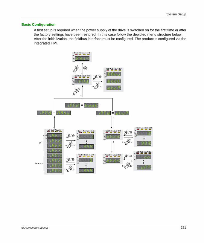
System Setup
Basic Configuration
A first setup is required when the power supply of the drive is switched on for the first time or after the factory settings have been restored. In this case follow the depicted menu structure below. After the initialization, the fieldbus interface must be configured. The product is configured via the integrated HMI.
EIO0000001680 11/2015 231

System Setup
For more information, refer to LXM32M, Modbus-TCP module, Fieldbus manual, 0198441113843.
When the drive is switched on and if the motor encoder is connected to the drive, the device automatically reads technical information on the motor such as nominal torque and peak torque, nominal current, nominal velocity and number of pole pairs. Without this information, the device is not ready for operation.
Further configurations like tuning, limit values and I/O configuration can be done on basis of the application. In this architecture, an auto tuning has been performed and for all other values the default settings were retained.
For more information, refer to LXM32M AC servo drive, Product manual, 0198441113767.
Step Action Comment
1 Switch on the drive. The power stage supply is switched off. Disconnect the drive from the fieldbus during
commissioning in order to avoid conflicts by simultaneous access.
Switch on the power supply of the controller.
2 Set the parameter [EthIpMode]:ConF -> CoM -> iPMd
Select the type of network address assignment. In this architecture, a fixed IP address is used for the drive: iPMd = MAnu
3 Set the parameters [EthIPmodule1]… [EthIPmodule4]:ConF -> CoM -> iPc1 … iPc4
Set the IP address of the interface module.Value: 0...255 for each of the 4 parameters
4 Set the parameters [EthIPmask1]… [EthIPmask4]:ConF -> CoM -> iPM ... iPM4
Set the subnet mask of the interface module.Value: 0...255 for each of the 4 parameters
5 Set the parameters [EthIPgate1]… [EthIPgate4]:ConF -> CoM -> iPG1… iPG4
Set the IP address of the gateway of the interface module.Value: 0...255 for each of the four parametersIn this example, the gateway address is equal to the IP address (Ethernet 2) of the controller.
6 Set the parameter [EthMode]:ConF -> CoM -> EtMd
Set the protocol for the Ethernet communication. In this architecture, the Modbus TCP protocol is used.EtMd = MtCP
NOTE: In addition to the [EthMode] the parameter [EthMbScanner] must stay enabled (default).
232 EIO0000001680 11/2015
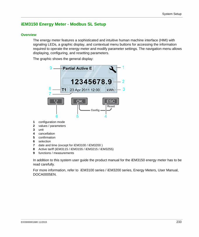
System Setup
iEM3150 Energy Meter - Modbus SL Setup
Overview
The energy meter features a sophisticated and intuitive human machine interface (HMI) with signaling LEDs, a graphic display, and contextual menu buttons for accessing the information required to operate the energy meter and modify parameter settings. The navigation menu allows displaying, configuring, and resetting parameters.
The graphic shows the general display:
1 configuration mode2 values / parameters3 unit4 cancellation5 confirmation6 selection7 date and time (except for iEM3100 / iEM3200 ) 8 Active tariff (iEM3115 / iEM3155 / iEM3215 / iEM3255)9 functions / measurements
In addition to this system user guide the product manual for the iEM3150 energy meter has to be read carefully.
For more information, refer to iEM3100 series / iEM3200 series, Energy Meters, User Manual, DOCA0005EN.
EIO0000001680 11/2015 233

System Setup
Configuration
Before starting the configuration of the energy meter, verify and ensure that your equipment is properly installed and the application functions correctly:
NOTE: Further configuration can be done depending on your application needs. For more information, refer to iEM3100 series / iEM3200 series, Energy Meters, User Manual, DOCA0005EN.
Step Action Comment
1 Set date and time. When the power is interrupted, the iEM3150 automatically resets the date and time.The start screen after power-on prompts you to set the date and time.
2 Enter the configuration mode.Press and hold ESC + OK for at least 2 seconds.
The display switches to configuration mode.
3 Select the submenu Wiring and set the parameter for it.
The default wiring parameter is set to 3PH4W.
4 Select the submenu Frequency and set the parameter for it.
The default frequency parameter is set to 50 Hz.
5 Select the submenu Communication and set the slave address, baud rate, and parity for it.
The default values of the parameters are set to: slave address = 1 baud rate = 19200 parity = even
6 Leave the setup menu by pressing ESC . –
234 EIO0000001680 11/2015

System Setup
Harmony ZBRN1 Access Point - Modbus TCP Setup
Overview
To operate the Harmony wireless receiver via Ethernet, the communication parameters have to be set for the device.
There are several options to configure the drive: by the local HMI on the front of the drive by web pages via PC* by the FDT/DTM integrated in SoMachine installed on a PC*
(* linked to the communication port on the bottom of the device)
EIO0000001680 11/2015 235

System Setup
Basic Configuration
After configuring the communication parameters, you have the opportunity to teach up to 60 wireless push-buttons. To configure the wireless receiver, use the jog dial on front of the device.
Before configuring the devices, connect the receiver module to the power supply and place the wireless push button within reach of the receiver module.
Steps to configure the ZBRN1
For more information, refer to Harmony XB5R, ZBRN1/ZBRN2, User Manual, EIO0000001177 (EN).
Step Action Comments
1 Configure the communication parameters under menu:Configuration [Conf] Ethernet [Et.••] DHCP [d•••] BootP [bP] Static IP [St]
- IP address [IP]- Subnet mask [SnN]- Gateway [gate]- Save [Save]
Save your settings.
Depending on your network select DHCP, BootP or Static IP.By selecting Static IP you have to set the 4 bytes of the IP address, Subnet mask and Gateway.
2 Set the input to teaching mode:Configuration [Conf] Inputs [in.••] Unteached input •• [i ••]
- Teach[t] --- Teach [t] (blinking)
How to recognize whether an input is already taught:
1 taught2 not taught
3 Teach the wireless push button by pushing it 3 times while it is blinking.
4 Unteach a battery less push button:Configuration [Conf] in.•• i._••
- Clr
5 Configure the holding time:Configuration [Conf] Hd.••
The input holding time can be set to: Hd. 1 = 100 ms Hd. 2 = 200 ms Hd. 3 = 300 ms Hd. 4 = 400 ms Hd.5 = 500 ms Hd.10 = 1 s
236 EIO0000001680 11/2015
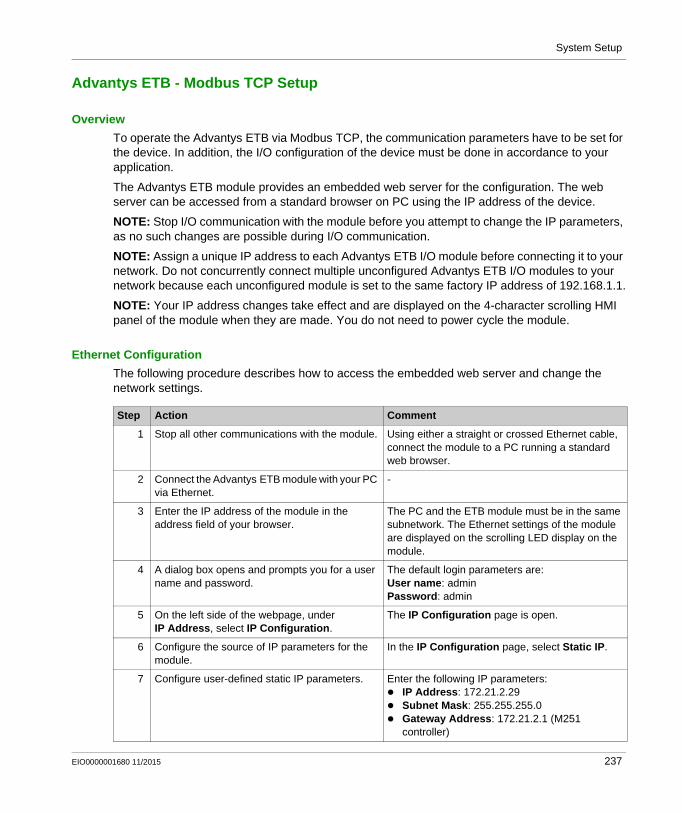
System Setup
Advantys ETB - Modbus TCP Setup
Overview
To operate the Advantys ETB via Modbus TCP, the communication parameters have to be set for the device. In addition, the I/O configuration of the device must be done in accordance to your application.
The Advantys ETB module provides an embedded web server for the configuration. The web server can be accessed from a standard browser on PC using the IP address of the device.
NOTE: Stop I/O communication with the module before you attempt to change the IP parameters, as no such changes are possible during I/O communication.
NOTE: Assign a unique IP address to each Advantys ETB I/O module before connecting it to your network. Do not concurrently connect multiple unconfigured Advantys ETB I/O modules to your network because each unconfigured module is set to the same factory IP address of 192.168.1.1.
NOTE: Your IP address changes take effect and are displayed on the 4-character scrolling HMI panel of the module when they are made. You do not need to power cycle the module.
Ethernet Configuration
The following procedure describes how to access the embedded web server and change the network settings.
Step Action Comment
1 Stop all other communications with the module. Using either a straight or crossed Ethernet cable, connect the module to a PC running a standard web browser.
2 Connect the Advantys ETB module with your PC via Ethernet.
-
3 Enter the IP address of the module in the address field of your browser.
The PC and the ETB module must be in the same subnetwork. The Ethernet settings of the module are displayed on the scrolling LED display on the module.
4 A dialog box opens and prompts you for a user name and password.
The default login parameters are:User name: adminPassword: admin
5 On the left side of the webpage, under IP Address, select IP Configuration.
The IP Configuration page is open.
6 Configure the source of IP parameters for the module.
In the IP Configuration page, select Static IP.
7 Configure user-defined static IP parameters. Enter the following IP parameters: IP Address: 172.21.2.29 Subnet Mask: 255.255.255.0 Gateway Address: 172.21.2.1 (M251
controller)
EIO0000001680 11/2015 237

System Setup
I/O and Watchdog Configuration
You can configure the I/O and watchdog settings of the Advantys ETB I/O module using either the controller or webpages.
Configuring I/O settings and watchdog via the controller simplifies module replacement because the configuration is stored on the controller and does not have to be reconfigured in the webpages when a module is replaced.
The embedded webpages offer a method for configuring the I/O and watchdog settings of the module. However, configuration settings made to a module via its webpages cannot be transferred to a replacement module.
The ETB1EM16CP00 module contains configurable I/O points that can be configured for IN, OUT, or IN/OUT. This topic shows you how to configure the I/O points of the ETB1EM16CP00 module and only applies to this specific module.
NOTE: By default, each point is pre-configured as an auto-configurable (IN/OUT) I/O point.
8 Click Apply to save your static IP parameters. A dialog opens where you need to confirm the applying of the changes.
9 Click OK to accept your IP parameter changes. The changes are taking effect immediately. Depending on your changes, probably you lose the connection to the module.
10 Look at the scrolling 4-character HMI of the module to verify that the intended IP address is displayed.
-
Step Action Comment
Step Action Comment
1 Connect and logon to the module using a web browser.
See the described procedure under Ethernet configuration above.
2 On the left side of the webpage, under I/O Configuration, select IN/OUT Configuration.
The IN/OUT Configuration page is open.
3 Select an I/O Type for each point. IN: the selected point is configured as an input OUT: the selected point is configured as an
output IN/OUT: the selected point auto-configures as
an: Input, if it detects that it is connected to a
sensor, or Output, if it detects that it is connected to an
actuator
4 Select the Input Type for all points acting as inputs.
You can select one type which is applied for all inputs: PNP NPN
238 EIO0000001680 11/2015

System Setup
During normal operations, each Advantys ETB I/O module remains in continuous communication with the Modbus master (usually a controller). If communication with the Modbus master is lost, the behavior of the outputs of the Advantys ETB I/O module is governed by its watchdog settings.
The following settings are configurable:
For more information, refer to Advantys ETB, IP67 Ethernet Block I/O Modules for Modbus TCP/IP, User Guide, EIO0000000158.
5 Click Apply to save your I/O configuration changes.
The changes become effective.
6 Select an Input Filter value. Valid values include: 0 ms 0.5 ms 1 ms 1.5 ms 2 ms 2.5 ms 5 ms
Step Action Comment
Setting Description
Watchdog Timeout The time period, in milliseconds, that the module waits after the communication with the Modbus master is lost and before adopting the pre-configured Watchdog Behavior.
Watchdog Behavior The behavior that the output points of the module adopt if communication with the Modbus master is lost for a continuous period greater than the Watchdog Timeout.Choices are: Apply Output Fallback Value: places each output into a
pre-configured on or off state, or Hold Output Value: maintains the state of each output at
the time communication with the Modbus master is lost.
Fallback Value (for each output point) The pre-determined state, on or off, each output point adopts if communication with the Modbus master is lost for a time period longer than the Watchdog Timeout.
EIO0000001680 11/2015 239

System Setup
Diagnostics
The scrolling LED of the module displays messages for you to verify the status of the module.
During normal operation, only the source of the IP address, the address itself, and the state of the I/O scanning is displayed. The HMI shows the following specific data when available.
Source information displayed on the HMI:
IP address information displayed on the HMI:
Module status information displayed on the HMI:
Message Description
DHCP The module is waiting for a response from a DHCP server.
BOOT The module is waiting for a response from a BootP server.
FACT The module is applying the factory IP address of 192.168.1.1.
Message Description
DHCP:192.168.1.1 The IP address of 192.168.1.1 was acquired by a DHCP server.
BOOTP:192.168.1.1 The IP address of 192.168.1.1 was acquired by a BootP server.
FACTORY:192.168.1.1 The IP address is set to the factory IP address of 192.168.1.1.
STATIC:192.168.1.21 The IP address of 192.168.1.21 was manually set by the user, either through the embedded webpages or push buttons.
DEFx The module detects an IP conflict and defends its own IP address.
NOTE: x: number of times the module defends its IP address
IP CONFLICT on 192.168.1.1
The module detects an IP address conflict on 192.168.1.1.
Message Description
WLNK There is no Ethernet link on any ports of the switch.
PING The module is receiving PING requests on the network.
IO:ERR A detected I/O error exists on one or more points.
WD:ACTIV The watchdog was triggered and is now active.
240 EIO0000001680 11/2015

System Setup
ConneXium TCSESM Ethernet Switch - Setup
Overview
The Ethernet switch has been developed for practical application in a harsh industrial environment. So, the installation process has been kept simple.
Thanks to the selected default settings, you only have to enter a few settings before starting to operate the device. The IP parameters must be entered when the device is installed for the first time.
There are several options to configure the Ethernet switch: By the Command Line Interface (CLI) By the Ethernet switch configurator software protocol By the Memory Backup Adaptor (EAM) By BOOTP By DHCP By DHCP option 82 By web-based interface
NOTE: If a device has already been configured for some other use, re-establish the factory settings. Instructions on how to do this can be found in the respective documentation.
Basic Configuration
The following procedure describes how to change the network settings using the Ethernet switch configurator software protocol.
Step Action Comment
1 Install the Ethernet Switch Configurator Software on your PC.
-
2 Connect the ConneXium Ethernet switch with your PC via Ethernet.
The Ethernet settings of the PC and the switch are not mandatory for the connection using the configurator software.
3 Start the Ethernet Switch Configurator Software program.
When the software is started, a scan is automatically executed for the selected Ethernet adapter.
4 Identify the devices displayed:Select a device line.
The software displays a line for each device which responds to the Ethernet switch configurator software protocol.
5 Click the signal symbol in the toolbar to set the LEDs for the selected device flashing.
To switch off the flashing, click the symbol again.
6 Double-click a line to open a dialog box where you can enter the device name and the IP parameters.
IP address = 172.21.2.2 Subnet mask= 255.255.255.0 Default Gateway = 172.21.2.1 (M251 controller)
7 Click OK. The selected IP parameters are immediately applied and stored on the device.
EIO0000001680 11/2015 241

System Setup
After entering the IP address, the web-based interface can be used to configure the managed Ethernet switch. The ConneXium TCSESM can be addressed by any web browser (for example, Internet Explorer, Firefox and so on).
NOTE: Before you begin, verify that both your PC and the ConneXium Ethernet switch are configured with IP addresses that are located in the same subnet (or, alternatively, are connected via a routing mechanism).The ConneXium manged Ethernet switch provide you with a range of functions to manage your network. These are, among others,: Redundancy Network security Synchronized system time in the network Network load control Operation diagnostics
The following procedure describes how to: Access the embedded web server Configure the Port Mirroring Disable the Ethernet Switch Configurator Software function
Step Action Comment
1 Start your web browser. -
2 Connect the ConneXium Ethernet switch with your PC via Ethernet.
The PC and the switch must be in the same subnetwork.
3 Enter the configured IP address using the following form:http://xxx.xxx.xxx.xxx
A dialog box opens and prompts you for a user name and password.
4 Enter the factory default settings for user name and password.
User name: adminPassword: private
NOTE: If you previously changed the password, you must enter the new password in this dialog box. See important safety-related information below.
5 Click OK. The website of the device is displayed.
6 In the Diagnostics menu, select Port Mirroring.
-
7 Activate the check mark Operation On. -
8 Select the destination port. All network traffic from the selected source port(s) is forwarded to the selected destination port.9 Select one or more source ports.
10 Click the Set button. The port mirroring configuration is applied immediately.
11 In the Basics menu, select Network. -
242 EIO0000001680 11/2015

System Setup
Change the default password upon first use. In addition, consider carefully the implications for giving any access to other people.
NOTE: A secure password is one that has not been shared or distributed to any unauthorized personnel and does not contain any personal or otherwise obvious information. Further, a mix of upper and lower case letters and numbers offer greater security. You should choose a password length of at least seven characters.
12 Disable the Ethernet Switch Configurator Software function in the Ethernet Switch Configurator Software Protocol frame or limit the access to read-only.
This helps to prevent unwanted or unauthenticated access to the IP configuration of the device.
NOTE: See important safety-related information below.
13 In the Basics menu, select Load/Save. NOTE: To save all changes made, so that they will be retained after a power cycle or restart of the device, use the save option in the Load/Save dialog.
14 Select Save to Device and click the Save button.
-
WARNINGUNAUTHORIZED DATA ACCESS
Immediately change any and all default passwords to new, secure passwords. Do not distribute passwords to unauthorized or otherwise unqualified personnel.
Failure to follow these instructions can result in death, serious injury, or equipment damage.
WARNINGUNAUTHENTICATED ACCESS
Disable the Ethernet Switch Configurator Software function to prevent any unwanted or unauthenticated access to the IP configuration of the device.
Failure to follow these instructions can result in death, serious injury, or equipment damage.
Step Action Comment
EIO0000001680 11/2015 243

System Setup
For more information about the other security settings for the ConneXium TCSESM managed Ethernet switch refer to: ConneXium Ethernet Cabling System TCSESM, TCSESM-E Managed Switch Basic
Configuration, User Manual, 31007122 ConneXium TCSESM, TCSESM-E, Managed Switch, Web-based Interface, Reference Manual,
EIO0000000482
244 EIO0000001680 11/2015

System Setup
Absolute Encoder - Modbus TCP Setup
Overview
To operate the absolute rotary encoder via Modbus TCP, the communication parameters have to be set for the device.
The absolute rotary encoder can be addressed by a web browser (for example, Internet Explorer, Firefox, and so on.)
NOTE: Before you begin, verify that both your PC and the encoder are configured with IP addresses that are located in the same subnet (or, alternatively, are connected via a routing mechanism).
Basic Configuration
The following procedure describes how to access the embedded web server and change the network settings.
For more information, refer to the associated user manual for absolute rotary encoders with Modbus TCP interface provided by BEI Sensors.
Step Action Comment
1 Connect the encoder to a PC via Ethernet. -
2 Open a web browser. -
3 Enter the IP address of the encoder in the address line of the browser and press Enter on your keyboard.
The factory default address is http://10.10.10.10.
4 Open the E-Mail and Network Configuration page.
-
5 Set the parameters of the encoder. IP address = 172.21.2.28 Subnet mask= 255.255.255.0 Default Gateway = 172.21.2.1 (M251
controller)
6 Click the Set button to apply the settings. -
7 Power-cycle the encoder (power off and on) to apply the new settings.
-
EIO0000001680 11/2015 245
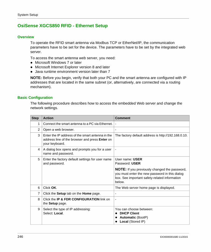
System Setup
OsiSense XGCS850 RFID - Ethernet Setup
Overview
To operate the RFID smart antenna via Modbus TCP or EtherNet/IP, the communication parameters have to be set for the device. The parameters have to be set by the integrated web server.
To access the smart antenna web server, you need: Microsoft Windows 7 or later Microsoft Internet Explorer version 8 and later Java runtime environment version later than 7
NOTE: Before you begin, verify that both your PC and the smart antenna are configured with IP addresses that are located in the same subnet (or, alternatively, are connected via a routing mechanism).
Basic Configuration
The following procedure describes how to access the embedded Web server and change the network settings.
Step Action Comment
1 Connect the smart antenna to a PC via Ethernet. -
2 Open a web browser. -
3 Enter the IP address of the smart antenna in the address line of the browser and press Enter on your keyboard.
The factory default address is http://192.168.0.10.
4 A dialog box opens and prompts you for a user name and password.
-
5 Enter the factory default settings for user name and password.
User name: USERPassword: USER
NOTE: If you previously changed the password, you must enter the new password in this dialog box. See important safety-related information below.
6 Click OK. The Web server home page is displayed.
7 Click the Setup tab on the Home page. -
8 Click the IP & FDR CONFIGURATION link on the Setup page.
-
9 Select the type of IP addressing:Select: Local.
You can choose between: DHCP Client Automatic (BootP) Local (Stored IP)
246 EIO0000001680 11/2015

System Setup
Change the default password upon first use. In addition, consider carefully the implications for giving any access to other people.
NOTE: A secure password is one that has not been shared or distributed to any unauthorized personnel and does not contain any personal or otherwise obvious information. Further, a mix of upper and lower case letters and numbers offer greater security. You should choose a password length of at least seven characters.
For more information, refer to RFID OsiSense XG, Ethernet Smart Antenna, User Manual, EIO0000001601.
10 Set the parameters of the smart antenna. Depending on the selected IP mode set the parameters: DHCP: Enter a device name Local: Enter the IP address, the subnet mask,
and the gateway IP address (Ethernet 2 of the M251 controller)
11 Click Apply to validate the settings. -
12 Power-cycle the smart antenna (power off and on) to apply the new settings.
-
WARNINGUNAUTHORIZED DATA ACCESS
Immediately change any and all default passwords to new, secure passwords. Do not distribute passwords to unauthorized or otherwise unqualified personnel.
Failure to follow these instructions can result in death, serious injury, or equipment damage.
Step Action Comment
EIO0000001680 11/2015 247

System Setup
Diagnostics
The 6 two-tone LEDs display the operating states of the OsiSense XG smart antenna.
LED Name LED state Description Smart antenna state
1 TAG Solid green Tag presence A tag is detected, communication ok
1 flash No tag detected Waiting for a tag
Red flashes RFID detected error Errors detected in the communication with the tag
2 COM Green flashes
Requests received from a client Ok
Red flashes Detected error in requests received from a client
Detected error code returned to the client (no tag / incorrect parameters, etc.)
3 NS (Network status)
Steady off Not powered or no IP address Waiting for IP address setting (fixed or DHCP).
Flashing green
No connections No CIP connection established, and an exclusive owner connection with a client has not timed out.
Solid green Connected At least one CIP connection is established, and an exclusive owner connection with client has not timed out.
Flashing red Connection timeout An exclusive owner connection with client has timed out.
Solid red Duplicate IP The smart antenna has detected that its IP address is already in use.
Flashing green/red
Self-test The smart antenna is performing its power-on self-test.
248 EIO0000001680 11/2015

System Setup
4 Link activity (port 1 and 2)
Solid green Ethernet link present at 100 Mbit/s
Ok
5 Flashing green
Traffic at 100 Mbit/s Ok
Solid yellow Ethernet link present at 10 Mbit/s
Ok
Flashing yellow
Traffic at 100 Mbit/s Ok
6 MS (Ethernet module status)
Solid green The Ethernet module of the smart antenna is operational
Ok
Flashing green
Standby The smart antenna is waiting for network configuration.
Flashing red Recoverable error The smart antenna has detected a recoverable error.
NOTE: An incorrect or inconsistent configuration is considered as a recoverable error.
Steady red Non-recoverable error The smart antenna has detected a non-recoverable error on its Ethernet module.
Flashing green/red
Self-test The smart antenna is performing its power-on self-test.
LED Name LED state Description Smart antenna state
EIO0000001680 11/2015 249

System Setup
250 EIO0000001680 11/2015

Distributed Modbus TCP Logic Controller M251
Adapt TVDA Template
EIO0000001680 11/2015
Adapt TVDA Template
Chapter 8Adapt TVDA Template
What Is in This Chapter?
This chapter contains the following sections:
Section Topic Page
8.1 Adapt SoMachine Project Template 252
8.2 Adapt HMI Application 259
EIO0000001680 11/2015 251

Adapt TVDA Template
Adapt SoMachine Project Template
Section 8.1Adapt SoMachine Project Template
What Is in This Section?
This section contains the following topics:
Topic Page
Introduction 253
Device Modules in General 254
Device Modules Used in This Project Template 255
Add Device Modules 256
Remove Device Module 258
252 EIO0000001680 11/2015

Adapt TVDA Template
Introduction
Overview
The structure of a TVDA project template has a modular design thanks to the use of Device Modules.
This allows you to create your customized project in an easy and flexible way by adapting the TVDA project template.
EIO0000001680 11/2015 253

Adapt TVDA Template
Device Modules in General
Overview
The Device Modules out of the TVDA Device Module Library are represented by Function Templates within SoMachine. They are especially created for the TVDA project template.
Device Modules are available for the functional units implemented in the different TVD architectures.
By definition functional units in the extent of Device Modules are different sorts of field devices controlled (connected) in various ways by the controller.
The required SoMachine application content, beginning with integrating the device to the hardware configuration up to integration of the needed program code, is provided.
Each Device Module comes with its own global variable definition and helps to ensure consistency within the application.
During the device module insertion process, the software prompts you to assign the required configuration such as addresses, names, variable assignment to I/Os, and parameter assignment. (Refer to Add Device Module (see page 256).)
Each Device Module provides a ready to use interface within the application program to control the device and to monitor its status.
254 EIO0000001680 11/2015

Adapt TVDA Template
Device Modules Used in This Project Template
Device Modules Used
The following Device Modules of the TVDA Device Module Library are used in this project template.
Refer to TVDA Device Module Library (see TVDA Device Module Library, Function Template Library Guide).
Device Module
MED_iEM3150_ModbusSL
Harmony_Wireless_ModbusTCP_2
ATV32_EtherNetIP
ATV71_EtherNetIP
Lexium_32M_EtherNetIP
Lexium_ILA2K_EtherNetIP
Lexium_ILE2K_EtherNetIP
Lexium_ILS2K_EtherNetIP
Preventa_XPSMCM_EtherNetIP
OsiSense_XUW_EtherNetIP
OsiSense_RFID_EtherNetIP
EIO0000001680 11/2015 255

Adapt TVDA Template
Add Device Modules
Procedure
To add a Device Module, proceed as follows:
NOTE: For Device Modules associated with a fieldbus, the appropriate fieldbus master has to be available in your project. For example, the Device Module ATV32_ModbusTCP requires a Industrial Ethernet manager in the project configuration.
Step Action
1 Right-click the Application node in the Application tree and select Add Function From Template from the context menu.The Add Function From Template dialog box is displayed.
2 Enter a Function Name that is used for the new folder of the Device Module and for the naming of the elements it contains (GVL, POU, POU call, device, and so on).
3 Click the ... button and select a Device Module (Function Template) from the TVDA Device Module Library. Confirm with OK.
4 Now you can edit the different properties. Which properties can be edited depends on the selected Device Module.
5 For Device Modules which include a field device, the appropriated fieldbus master is preselected in the Master column of the I/O Devices field. If your configuration includes more than one fieldbus masters for the selected I/O Device, you can select the desired fieldbus master from the Select Fieldbus Master dialog box. This dialog box is open when you click the ... button.
6 For Device Modules which include a field device, the device address must be selected. In Address column of the I/O Devices field the address must be entered respectively it can be selected from the Select Device Address dialog box. This dialog box is open when you click the ... button.
7 The I/O Mapping field is an optional feature. For some Device Modules, it is possible to map variables directly to I/Os of current I/O configuration.In Mapping column of the I/O Mapping field, click the ... button to open the Select I/O Mapping dialog box and map the variable to a Channel of your I/O configuration. Confirm with OK.
8 In New Value column of the Parameters field, you can enter an initial value for the displayed variables (for example constants).If you do not enter a value, the Default value is used in your project.
9 Click the OK button to add the Device Module to your project.
256 EIO0000001680 11/2015

Adapt TVDA Template
Objects Added
If you add a Device Module, the associated objects are added to the project at the appropriate position. Information on what was done when adding the Device Module, is displayed in the Messages window.
Potential objects and actions are listed in the table.
Object Description
Root folder A new folder is added under the Application node in the Tools tree that is named as defined in the Function Name text box in the Add Function From Template dialog box.
GVL (global variable list) The global variable list that is included in the Device Module is added below the root folder using the Function Name.For example GVL_ATV32_ModbusTCP.
POU (program organization unit)
The POU that is included in the Device Module is added below the root folder using the Function Name.For example Prg_ ATV32_ModbusTCP (PRG).
POU call The call of the POU that is included in the Device Module is added below Task Configuration → MAST.
Device A device (if part of the Device Module) is added below the respective fieldbus master (for example Ethernet_2 → Industrial Ethernet manager) as selected in the Select Fieldbus Master dialog box.For example ATV32_ModbusTCP.
I/O mapping Variables mapped in the Add Function From Template dialog box (I/O Mapping field), appear in the device editor of the respective device.
Libraries Libraries referenced by the Device Module are automatically added to the Library Manager of your project.
EIO0000001680 11/2015 257

Adapt TVDA Template
Remove Device Module
Procedure
By adding (see page 256) a Device Module, various objects are added to your project.
To remove a functional unit (based on a Device Module) from your project, you have to remove the following objects manually from your project.
Objects to be Removed
Object Description
Root folder Remove the folder of the Device Module under the Application node in the Tools tree.
GVL (global variable list) As the GVL is part of the root folder, it is removed with the root folder.
POU (program organization unit)
As the POU is part of the root folder, it is removed with the root folder.
POU call Remove the POU call of the Device Module from Task Configuration.
Device Remove the device (if part of the Device Module) from the respective fieldbus (for example Ethernet_2 → Industrial Ethernet manager).
Variables Remove the variables coming from your Device Module and being used in the project. For example in the Symbol configuration or in the I/O mapping.
Libraries Remove the libraries referenced by the Device Module from the Library Manager of your project (if they are not referenced by other objects in your project).
258 EIO0000001680 11/2015

Adapt TVDA Template
Adapt HMI Application
Section 8.2Adapt HMI Application
Introduction
Overview
The provided HMI application is a general solution.
Since every machine needs its own specific interface, the provided HMI application will in all likelihood not match exactly your requirements. Therefore, you will need to modify the provided HMI application using the Vijeo-Designer configuration software.
Vijeo-Designer is an efficient and flexible tool. It provides numerous functions to facilitate the creation or adaptation of the HMI application.
Especially for an easy adaptation, the following features are highlighted: Objects can be saved as templates in tool chest. Placeholder in variable expressions can be used. Resources for object design can be used. Export/import function is available. Master panels can be used.
If desired, the provided HMI application can be used as pattern for your solution.
EIO0000001680 11/2015 259

Adapt TVDA Template
260 EIO0000001680 11/2015

Distributed Modbus TCP Logic Controller M251
Bill of Material
EIO0000001680 11/2015
Bill of Material (BOM)
Chapter 9Bill of Material (BOM)
Bill of Material (BOM)
Overview
In this chapter, a Bill of Materials (BOM) for the main components of the architecture is provided.
Components and component combinations of the protection system of this architecture are marked with additional information about the conformity to standards IEC and UL. Those which are marked as UL can be considered as a multi-standard solution. Nonetheless, you must consider and respect the local standards and codes, as well as the electrical and environmental conditions, where the system is installed and operated. For more information on this topic, refer to the associated product manuals and on the Schneider Electric webpage.
Regardless of the industrial application of a control panel, its protection systems and devices must comply with applicable international standards: IEC 60-204 safety of machinery UL 508A industrial control panel
Components and component combinations that meet multiple standards are equally important to design and size for ensuring that control panels meet legal requirements across international markets.
For more information about the multi-standard offer of Schneider Electric, refer to the website http://www2.schneider-electric.com/sites/corporate/en/products-services/product-launch/multistandard-offer/multistandard-offer.page
Schneider Electric offers UL 508A support on the website at www.Schneider-Electric.us. A number of educational and product search tools are available on the website, including overview information, a UL 508A SCCR (Short Circuit Current Rating) determination flow chart, and information on Schneider Electric individual or product combination SCCRs. Underwriters Laboratories also publish SCCR tested combination ratings on its website. Updated tested combination ratings of Schneider Electric can be found on both websites and are free to download.
WARNINGREGULATORY INCOMPATIBILITY
Ensure that all equipment applied and systems designed comply with all applicable local, regional, and national regulations and standards.
Failure to follow these instructions can result in death, serious injury, or equipment damage.
EIO0000001680 11/2015 261

Bill of Material
The UL 508A support website of Schneider Electric is located at:
http://www.schneider-electric.us/sites/us/en/support/product-support-resources/ul-508a-support/ul-508a-support.page
The UL 508A combination motor controller website of UL is located at:
http://www.ul.com/global/eng/pages/offerings/industries/powerandcontrols/industrialcontrole-quipment
Main Switch
Energy meter
Quantity Description Reference IEC UL
Main cabinet
1 PowerPact H-Frame multistandard circuit breaker, main switch, 3pin, 35 kA, with factory sealed trip unit current rating 15 A
NHGF36015TW x x
1 Lug kit 15...150 A AL150HDS x x
1 Short lug shield S37446 x x
1 Red rotary handle on yellow bezel LV429340 x x
Remote cabinet
1 Vario main switch for panel mounting, 25 A VCD0 x x
1 Protective cover for terminals VZ8 x x
Quantity Description Reference IEC UL
1 Energy meter iEM3150, direct measurement up to 63 A, Modbus communication
A9MEM3150 x x
262 EIO0000001680 11/2015

Bill of Material
Emergency Stop
Display and Indicators
Quantity Description Reference
Main cabinet
1 Safety module emergency stop Cat. 4 TM3SAF5R
1 Emergency stop push-button, 2 NC, 22 mm, complete unit XB5AS8444
1 Emergency stop push-button, complete plastic control station, yellow/ red, 2 NC
XALK178F
1 Illuminated push-button, blue, 1 NO + 1 NC, integral LED, complete unit XB5AW36B5
1 Circular yellow legend for emergency stop push-button "emergency stop" ZBY8330
2 TeSys D contactor, AC-3 400 V / 7.5 kW LC1D18BD
Remote cabinet
1 Preventa safety module, emergency stop cat. 4 XPSAF5130P
1 Emergency stop push-button, 2 NC, 22 mm, complete unit XB5AS8444
1 Emergency stop push-button, complete plastic control station, yellow/ red, 2 NC
XALK178F
1 Illuminated push-button, blue, 1 NO + 1 NC, integral LED, complete unit XB5AW36B5
1 Circular yellow legend for emergency stop push-button "emergency stop" ZBY8330
2 TeSys D contactor, AC-3 400 V / 7.5 kW LC1D18BD
Quantity Description Reference
Main cabinet
1 Pilot light with integral LED 24 Vac/dc, white, complete unit XB5AVB1
1 Harmony Wireless access point ZBRN1
1 Communication module (Modbus TCP) for ZBRN1 ZBRCETH
1 Plastic control station, empty, 2 cut-outs, IP 66 XALD02
1 Wireless push-button green ZB5RTA3
1 Wireless push-button red ZB5RTA4
1 Empty plastic box for mobile transmitter, 1 cut-out ZBRM01
1 Wireless push-button blue ZB5RTA6
1 Plastic control station, empty, 3 cut-outs, IP 66 XALD03
2 Push-button, green, 1 NO, complete unit XB5AA31
1 Push-button, red, 1 NC, complete unit XB5AA42
5 Legend holder and blank label (white or yellow) 18x27 mm ZBY6102
1 Fixing plate for use on vertical support of tower light XVBC12
EIO0000001680 11/2015 263

Bill of Material
Automation Components
1 Fixing base with support tube 80 mm, black XVBZ02
1 Base unit for tower light XVBC21
1 Set of 6 colored markers for the position XVBC22
1 Signal element for tower light, green XVBC2B3
1 Signal element for tower light, red XVBC2B4
1 Signal element for tower light, blue XVBC2B6
1 Signal element for tower light, clear XVBC2B7
Remote cabinet
1 Pilot light with integral LED 24 Vac/dc, white, complete unit XB5AVB1
Quantity Description Reference
Quantity Description Reference
Main cabinet
1 Modicon M251 Logic Controller 24 Vdc, 2x Ethernet TM251MESE
1 TM3 expansion module 16 DI TM3DI16
1 TM3 expansion module 16 DO TM3DQ16T
Remote cabinet
1 Distributed I/O module, Ethernet (Modbus TCP), 12 DI, 8 DO OTB1E0DM9LP
2 TM2 expansion module 16 DI, 8 DO TM2DMM24DRF
1 TM2 expansion module 16 DI TM2DDI16DT
1 TM2 expansion module 8 DO TM2DDO8TT
1 TeSys splitterbox to connect motor starters with parallel wiring module, 8x RJ45 connectors
LU9G02
2 Prewired cable with HE10 connector at one end and flying leads at the other end, 3 m (9.84 ft)
TSXCDP301
Field
1 Advantys ETB I/O module Modbus TCP, IP 67, 16 DIO ETB1EM16CP00
1 Power cable for Advantys ETB I/O module (7/8 elbowed, single ended), 2 m (6.57 ft)
ETXPC511M400020
264 EIO0000001680 11/2015
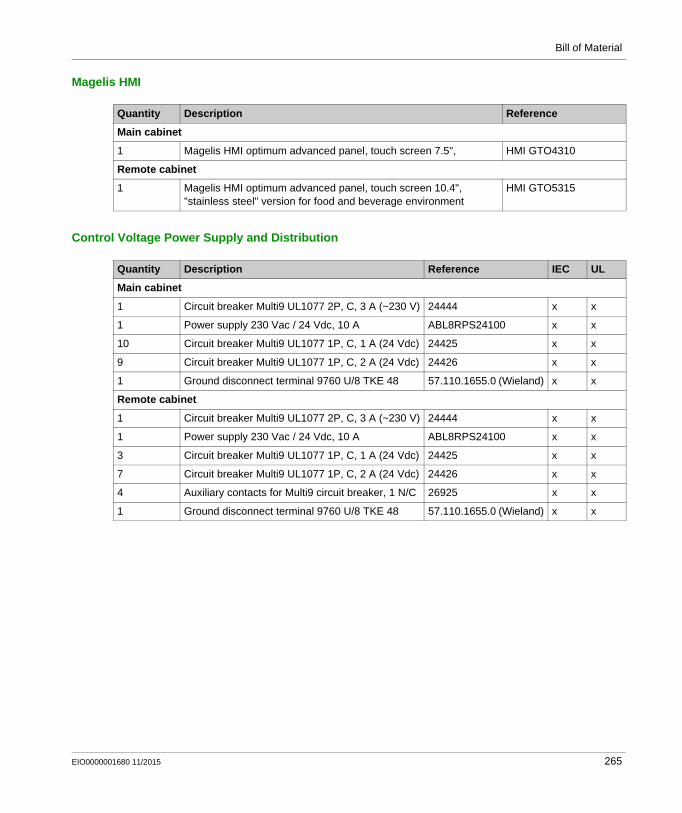
Bill of Material
Magelis HMI
Control Voltage Power Supply and Distribution
Quantity Description Reference
Main cabinet
1 Magelis HMI optimum advanced panel, touch screen 7.5", HMI GTO4310
Remote cabinet
1 Magelis HMI optimum advanced panel, touch screen 10.4", "stainless steel" version for food and beverage environment
HMI GTO5315
Quantity Description Reference IEC UL
Main cabinet
1 Circuit breaker Multi9 UL1077 2P, C, 3 A (~230 V) 24444 x x
1 Power supply 230 Vac / 24 Vdc, 10 A ABL8RPS24100 x x
10 Circuit breaker Multi9 UL1077 1P, C, 1 A (24 Vdc) 24425 x x
9 Circuit breaker Multi9 UL1077 1P, C, 2 A (24 Vdc) 24426 x x
1 Ground disconnect terminal 9760 U/8 TKE 48 57.110.1655.0 (Wieland) x x
Remote cabinet
1 Circuit breaker Multi9 UL1077 2P, C, 3 A (~230 V) 24444 x x
1 Power supply 230 Vac / 24 Vdc, 10 A ABL8RPS24100 x x
3 Circuit breaker Multi9 UL1077 1P, C, 1 A (24 Vdc) 24425 x x
7 Circuit breaker Multi9 UL1077 1P, C, 2 A (24 Vdc) 24426 x x
4 Auxiliary contacts for Multi9 circuit breaker, 1 N/C 26925 x x
1 Ground disconnect terminal 9760 U/8 TKE 48 57.110.1655.0 (Wieland) x x
EIO0000001680 11/2015 265
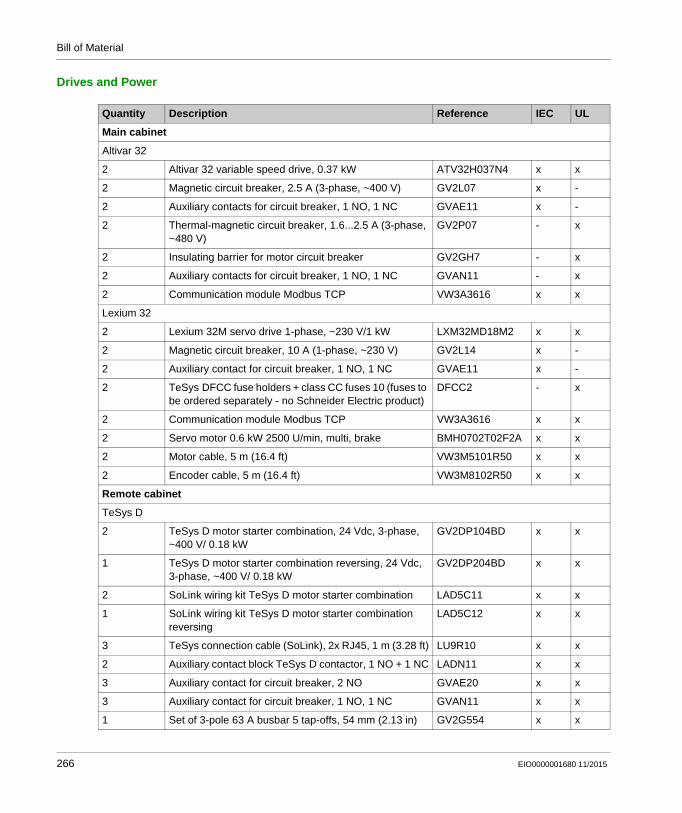
Bill of Material
Drives and Power
Quantity Description Reference IEC UL
Main cabinet
Altivar 32
2 Altivar 32 variable speed drive, 0.37 kW ATV32H037N4 x x
2 Magnetic circuit breaker, 2.5 A (3-phase, ~400 V) GV2L07 x -
2 Auxiliary contacts for circuit breaker, 1 NO, 1 NC GVAE11 x -
2 Thermal-magnetic circuit breaker, 1.6...2.5 A (3-phase, ~480 V)
GV2P07 - x
2 Insulating barrier for motor circuit breaker GV2GH7 - x
2 Auxiliary contacts for circuit breaker, 1 NO, 1 NC GVAN11 - x
2 Communication module Modbus TCP VW3A3616 x x
Lexium 32
2 Lexium 32M servo drive 1-phase, ~230 V/1 kW LXM32MD18M2 x x
2 Magnetic circuit breaker, 10 A (1-phase, ~230 V) GV2L14 x -
2 Auxiliary contact for circuit breaker, 1 NO, 1 NC GVAE11 x -
2 TeSys DFCC fuse holders + class CC fuses 10 (fuses to be ordered separately - no Schneider Electric product)
DFCC2 - x
2 Communication module Modbus TCP VW3A3616 x x
2 Servo motor 0.6 kW 2500 U/min, multi, brake BMH0702T02F2A x x
2 Motor cable, 5 m (16.4 ft) VW3M5101R50 x x
2 Encoder cable, 5 m (16.4 ft) VW3M8102R50 x x
Remote cabinet
TeSys D
2 TeSys D motor starter combination, 24 Vdc, 3-phase, ~400 V/ 0.18 kW
GV2DP104BD x x
1 TeSys D motor starter combination reversing, 24 Vdc, 3-phase, ~400 V/ 0.18 kW
GV2DP204BD x x
2 SoLink wiring kit TeSys D motor starter combination LAD5C11 x x
1 SoLink wiring kit TeSys D motor starter combination reversing
LAD5C12 x x
3 TeSys connection cable (SoLink), 2x RJ45, 1 m (3.28 ft) LU9R10 x x
2 Auxiliary contact block TeSys D contactor, 1 NO + 1 NC LADN11 x x
3 Auxiliary contact for circuit breaker, 2 NO GVAE20 x x
3 Auxiliary contact for circuit breaker, 1 NO, 1 NC GVAN11 x x
1 Set of 3-pole 63 A busbar 5 tap-offs, 54 mm (2.13 in) GV2G554 x x
266 EIO0000001680 11/2015

Bill of Material
Encoder
The encoders are designed for compatibility with the UL standard, but they are not certified.
1 Terminal block for supply busbar sets GV1G09 x x
1 Cover for unused busbar connection points GV1G10 x x
1 Altistart softstarter 3-phase, ~400 V/ 1.1 kW (3 A) ATS01N103FT x x
TeSys U
1 TeSys U base module, 12 A (without terminals) LUB120 x x
1 TeSys U base module reversing, 12 A (without terminals)
LU2BA0BL x x
2 TeSys U control unit, standard 0.15…0.6 A LUCAX6BL x x
1 TeSys U wiring kit coil LU9BN11C x x
1 TeSys U wiring kit coil (reversing) LU9MRC x x
2 TeSys U function module parallel wiring LUFC00 x x
1 Set of 3-pole 63 A busbar 2 tap-offs, 54 mm (2.13 in) GV2G254 x x
2 TeSys connection cable (SoLink), 2x RJ45, 1 m (3.28 ft) LU9R10 x x
Altivar 12 - 2 motors
1 Altivar 12 variable speed drive, 0.37 kW ATV12H037M2 x x
1 Magnetic circuit breaker, 6.3 A (1-phase, ~230 V) GV2L10 x -
1 Auxiliary contact for circuit breaker, 1 NO, 1 NC GVAE11 x -
1 Thermal-magnetic circuit breaker, 4.0...6.3 A (1-phase, ~240 V)
GV2P10 - x
1 Insulating barrier for motor circuit breaker GV2GH7 - x
1 Auxiliary contact for circuit breaker, 1 NO, 1 NC GVAN11 - x
4 TeSys D contactor, AC-3 400 V / 4 kW LC1D09BD x x
2 Auxiliary contact block TeSys D contactor, 1 NO, 1 NC LADN11 x x
2 Auxiliary contact for Multi9 circuit breaker 60137 x x
2 Circuit breaker Multi9 UL489 2P, C, 2 A (~230 V) 26925 x x
Quantity Description Reference IEC UL
Quantity Description Reference
1 Absolute multi-turn optical rotary encoder (4096 inc. x 8192 turns), Modbus TCP
MHM5-EM00B-1213-C100-PRM (BEI sensors)
1 Power cable encoder with 5-pin M12 connector at one end and flying leads at the other end, 2.0 m (6.56 ft)
XZCP1164L2
1 Encoder mounting bracket XCCRE5SN
EIO0000001680 11/2015 267

Bill of Material
Sensors
Ethernet Wiring
Quantity Description Reference
3 RFID smart antenna, Modbus TCP, IP 67 XGCS850C201
1 RFID electronic tag - 13.56 MHz - ISO badge 54 x 85.5 x 1 mm - 256 Kb (10 pc.)
XGHB90E340
3 Power cable smart antenna with M8 connector at one end and flying leads at the other end, 2.0 m (6.56 ft)
XZCP0941L2
Quantity Description Reference
Main cabinet
1 Ethernet TCP/IP managed switch, 10BASET/100BASE-TX, 8x RJ45 ports copper cable
TCSESM083F23F0
1 Memory backup adapter for managed Ethernet switch TCSEAM0100
4 Ethernet patch cable, 2x RJ45, cat. 7, green 0.5 m (1.64 ft) VW3E3001R005
1 1 m (3.28 ft) VW3E3001R010
5 2 m (6.56 ft) VW3E3001R020
1 3 m (9.8 ft) VW3E3001R030
4 ConneXium M12 to RJ45 Ethernet adapter TCSEAAF11F13F00
Remote cabinet
1 Ethernet TCP/IP unmanaged switch, 10BASET/100BASE-TX, 5x RJ45 ports copper cable
TCSESU053FN0
1 Ethernet patch cable, 2x RJ45, cat. 7, green 0.5 m (1.64 ft) VW3E3001R005
2 2 m (6.56 ft) VW3E3001R020
1 3 m (9.8 ft) VW3E3001R030
2 ConneXium M12 to RJ45 Ethernet adapter TCSEAAF11F13F00
Field
1 ConneXium Ethernet switch, unmanaged, IP 65, 5 ports M12 TCSESU051F0
1 Power cable Ethernet switch IP 67 with 5-pin M12 connector at one end and flying leads at the other end
2.0 m (6.56 ft) XZCP1164L2
4 Ethernet cable, 2 x M12 straight 1.0 m (3.28 ft) TCSECL1M1M1S2
4 Ethernet cable, 2 x M12 straight 3.0 m (9.8 ft) TCSECL1M1M3S2
268 EIO0000001680 11/2015
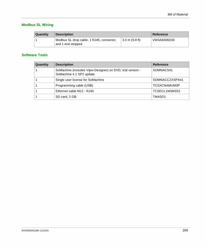
Bill of Material
Modbus SL Wiring
Software Tools
Quantity Description Reference
1 Modbus SL drop cable, 1 RJ45, connector, and 1 end stripped
3.0 m (9.8 ft) VW3A8306D30
Quantity Description Reference
1 SoMachine (includes Vijeo-Designer) on DVD, trial version - SoMachine 4.1 SP2 update
SOMNACS41
1 Single user license for SoMachine SOMNACCZXSPA41
1 Programming cable (USB) TCSXCNAMUM3P
1 Ethernet cable M12 - RJ45 TCSECL1M3M3S2
1 SD card, 2 GB TMASD1
EIO0000001680 11/2015 269

Bill of Material
270 EIO0000001680 11/2015

Distributed Modbus TCP Logic Controller M251
Glossary
EIO0000001680 11/2015
Glossary
B
BSHA Lexium servo motor from Schneider Electric.
C
CANopenAn open industry-standard communication protocol and device profile specification (EN 50325-4).
CFC(continuous function chart) A graphical programming language (an extension of the IEC 61131-3 standard) based on the function block diagram language that works like a flowchart. However, no networks are used and free positioning of graphic elements is possible, which allows feedback loops. For each block, the inputs are on the left and the outputs on the right. You can link the block outputs to the inputs of other blocks to create complex expressions.
CIP(common industrial protocol) When a CIP is implemented in a network application layer, it can communicate seamlessly with other CIP-based networks without regard to the protocol. For example, the implementation of CIP in the application layer of an Ethernet TCP/IP network creates an EtherNet/IP environment. Similarly, CIP in the application layer of a CAN network creates a DeviceNet environment. In that case, devices on the EtherNet/IP network can communicate with devices on the DeviceNet network through CIP bridges or routers.
CSA(Canadian standards association) The Canadian standard for industrial electronic equipment in hazardous environments.
D
DTM(device type manager) Classified into 2 categories: Device DTMs connect to the field device configuration components. CommDTMs connect to the software communication components.
The DTM provides a unified structure for accessing device parameters and configuring, operating, and diagnosing the devices. DTMs can range from a simple graphical user interface for setting device parameters to a highly sophisticated application capable of performing complex real-time calculations for diagnosis and maintenance purposes.
EIO0000001680 11/2015 271

Glossary
E
encoderA device for length or angular measurement (linear or rotary encoders).
EthernetA physical and data link layer technology for LANs, also known as IEEE 802.3.
EtherNet/IP(Ethernet industrial protocol) An open communications protocol for manufacturing automation solutions in industrial systems. EtherNet/IP is in a family of networks that implement the common industrial protocol at its upper layers. The supporting organization (ODVA) specifies EtherNet/IP to accomplish global adaptability and media independence.
expansion busAn electronic communication bus between expansion I/O modules and a controller.
F
FBD(function block diagram) One of 5 languages for logic or control supported by the standard IEC 61131-3 for control systems. Function block diagram is a graphically oriented programming language. It works with a list of networks, where each network contains a graphical structure of boxes and connection lines, which represents either a logical or arithmetic expression, the call of a function block, a jump, or a return instruction.
FDT(field device tool) The specification describing the standardized data exchange between the devices and control system or engineering or asset management tools.
G
GVL(global variable list) Manages global variables that can be passed between controllers on an Ethernet TCP/IP Modbus network.
H
HMI(human machine interface) An operator interface (usually graphical) for human control over industrial equipment.
272 EIO0000001680 11/2015

Glossary
I
I/O(input/output)
IEEE 802.3A collection of IEEE standards defining the physical layer, and the media access control sublayer of the data link layer, of wired Ethernet.
IL(instruction list) A program written in the language that is composed of a series of text-based instructions executed sequentially by the controller. Each instruction includes a line number, an instruction code, and an operand (refer to IEC 61131-3).
IP 20(ingress protection) The protection classification according to IEC 60529 offered by an enclosure, shown by the letter IP and 2 digits. The first digit indicates 2 factors: helping protect persons and for equipment. The second digit indicates helping protect against water. IP 20 devices help protect against electric contact of objects larger than 12.5 mm, but not against water.
IP 67(ingress protection) The protection classification according to IEC 60529. IP 67 modules are protected against ingress of dust, contact, and water up to an immersion depth of 1 m.
L
LD(ladder diagram) A graphical representation of the instructions of a controller program with symbols for contacts, coils, and blocks in a series of rungs executed sequentially by a controller (refer to IEC 61131-3).
M
MAC address(media access control address) A unique 48-bit number associated with a specific piece of hardware. The MAC address is programmed into each network card or device when it is manufactured.
MagelisThe commercial name for Schneider Electric's range of HMI terminals.
ModbusThe protocol that allows communications between many devices connected to the same network.
Modbus SL(Modbus serial line The implementation of the protocol over a RS-232 or RS-485 serial connection.
EIO0000001680 11/2015 273

Glossary
P
POU(program organization unit) A variable declaration in source code and a corresponding instruction set. POUs facilitate the modular re-use of software programs, functions, and function blocks. Once declared, POUs are available to one another.
Profibus DP(Profibus decentralized peripheral) An open bus system uses an electrical network based on a shielded 2-wire line or an optical network based on a fiber-optic cable. DP transmission allows for high-speed, cyclic exchange of data between the controller CPU and the distributed I/O devices.
R
RJ45A standard type of 8-pin connector for network cables defined for Ethernet.
RPI(requested packet interval) The time period between cyclic data exchanges requested by the scanner. EtherNet/IP devices publish data at the rate specified by the RPI assigned to them by the scanner, and they receive message requests from the scanner with a period equal to RPI.
RS-232A standard type of serial communication bus, based on 3 wires (also known as EIA RS-232C or V.24).
RS-485A standard type of serial communication bus, based on 2 wires (also known as EIA RS-485).
S
SFC(sequential function chart) A language that is composed of steps with associated actions, transitions with associated logic condition, and directed links between steps and transitions. (The SFC standard is defined in IEC 848. It is IEC 61131-3 compliant.)
SL(serial line)
SoMachineA comprehensive controller development system software tool for configuring and programming the Modicon logic controller and devices compliant with IEC 61131-3.
ST(structured text) A language that includes complex statements and nested instructions (such as iteration loops, conditional executions, or functions). ST is compliant with IEC 61131-3.
274 EIO0000001680 11/2015

Glossary
T
TCP(transmission control protocol) A connection-based transport layer protocol that provides a simultaneous bi-directional transmission of data. TCP is part of the TCP/IP protocol suite.
terminal block(terminal block) The component that mounts in an electronic module and provides electrical connections between the controller and the field devices.
TVDA(tested validated documented architectures) Control system proposals based on Schneider Electric components.TVDAs cover a wide range of machine types and consider machine performance requirements, installation constraints, and target costs. To optimize the implementation effort, each TVDA comes with a detailed component list, wiring diagrams, and commissioning guide, as well as controller and HMI applications to control components of the system.
EIO0000001680 11/2015 275

Glossary
276 EIO0000001680 11/2015

Distributed Modbus TCP Logic Controller M251
Index
EIO0000001680 11/2015
Index
HHMI application
TVDA, 251
MM251 Modbus TCP
SUG, 11TVDA, 11
Ssetup devices
TVDA, 213SUG (system user guide)
M251 Modbus TCP, 11system setup
TVDA, 213system user guide (SUG)
M251 Modbus TCP, 11
Ttemplate
TVDA, 191template, adapt
TVDA, 251TVDA
adapt template, 251communication, 157hardware, 61HMI application, 251implementation, 191M251 Modbus TCP, 11safety requirements, 29setup devices, 213template, 191wiring, 157
TVDA 17 Distributed Ethernet M251bill of material (BOM), 261
EIO0000001680 11/2015
TVDA M251 Ethernetsystem architecture, 24
277

Index
278
EIO0000001680 11/2015