distributed-memory multiprocessors in fpgas · resumo a explora˘c~ao do paralelismo em...
TRANSCRIPT
Distributed-Memory Multiprocessors in FPGAs
Francisco Jose Alves Correia Pires
Thesis to obtain the Master of Science Degree in
Electrical and Computer Engineering
Supervisor: Prof. Horacio Claudio de Campos Neto
Examination CommitteeChairperson: Prof. Nuno Cavaco Gomes Horta
Supervisor: Prof. Horacio Claudio de Campos NetoMember of the Committee: Dr. Pedro Filipe Zeferino Tomas
November 2015


Acknowledgments
Firstly, my sincerest thanks to Professor Horacio Neto and Professor Mario Vestias for their remarkable
guidance, patience and vast knowledge. My gratitude also goes out to fellow MSc and PhD students at
ESDA, especially to Joao Pinhao, Jose Canilho and Wilson Jose. Besides being cordial all the time, they
were always willing to help me in this work.
I also acknowledge my IST classmates that somehow helped or inspired me. At the risk of missing
some valuable friends, I must refer the following names: Andre Lopes, Andre Martins, Andre Santos,
Francisco Lemos, Jaime Carvalho, Joao Castro, Joao Guerreiro, Joao Mangas, Joao Maurıcio, Luıs Lima,
Maria Braga, Ricardo Silva, Rui Oliveira, Telmo Luıs and Tiago Marques. A very special thanks to Joao
Maurıcio for being like a brother over these harsh but gratifying years at IST.
Last but not least, a heartfelt thank you to my parents. Without their support, obtaining this degree
would be much harder. I extend my appreciation to my godparents, remaining family and friends.
This work was partially supported by national funds through FCT, Fundacao para a Ciencia e Tec-
nologia, under project DReaMaCHine - Design of a Reconfigurable Many-Core Architecture for High
Performance Computing (PTDC/EEA-ELC/122098/2010).


Abstract
The exploitation of parallelism in general purpose soft-core processors has been increasingly considered
an efficient approach to accelerate embedded applications. Therefore, it’s important to use standard
parallel programming paradigms that facilitate the development of parallel applications, abstracting the
architectural details from the user. The Message Passing Interface (MPI) is a standard library to develop
message-passing programs for distributed memory processing systems. This work proposes a Message
Passing Interface for FPGA soft-processors and Zynq heterogeneous systems. The work included the
definition of a fully functional set of MPI functions, which has been developed as a portable C library,
and the design of a set of configurable hardware components to support the communication between all the
processors. Considering the specifics of the target devices, namely the resource limitations in comparison
with supercomputers or clusters of workstations, the design emphasized low resource utilization as well as
hardware scalability and software reliability. A set of benchmarks covering a wide range of algorithms was
used to evaluate the work developed. The experimental results fully validated the implemented designs
and showed that standard MPI applications can be easily ported to the target platforms. Maximum
efficiencies (up to 100%) were achieved for the algorithms with lower communication overheads, such as
the cpi for pi calculus.
Keywords
Parallel Computing, High-Performance Computing, Embedded Systems, Soft-Processors, FPGAs,
MicroBlaze, Zynq, MPI
iii


Resumo
A exploracao do paralelismo em processadores soft-core e, cada vez mais, uma solucao adotada no
contexto de sistemas embebidos. Torna-se, por isso, necessaria a utilizacao de paradigmas de programacao
que facilitem o processo de desenvolvimento de aplicacoes paralelas e que abstraiam os pormenores da
arquitectura do sistema. Sendo a Message Passing Interface (MPI) um standard para bibliotecas que tem
em vista o desenvolvimento de programas em sistemas de memoria distribuıda, este trabalho apresenta
uma implementacao desta interface para processadores soft-core em FPGAs e em sistemas heterogeneos
Xilinx Zynq. O trabalho incluiu a definicao de um conjunto de funcoes MPI, implementadas sob a forma
de uma biblioteca portavel na linguagem C, e a arquitectura de uma serie de componentes de hardware
configuraveis de modo a possibilitarem a comunicacao entre os diferentes processadores. Tendo em conta
as caracterısticas dos dispositivos alvo, especialmente em comparacao com super computadores ou clus-
ters, a implementacao desenvolvida foca-se numa reduzida utilizacao de recursos da FPGA, tal como na
escalabilidade da arquitectura de comunicacao e na fiabilidade do software. Um conjunto de benchmarks
abrangendo diversos algoritmos foi utilizado com o objectivo de avaliar o trabalho desenvolvido. Os
resultados experimentais validaram a implementacao e demonstraram que aplicacoes MPI comuns sao
facilmente portaveis para os dispositivos alvo. Eficiencias de, aproximadamente, 100% foram atingidas
em algoritmos com baixo overhead de comunicacao, como o algoritmo cpi para o calculo do numero pi.
Palavras Chave
Computacao Paralela, Computacao de Alto Desempenho, Sistemas Embebidos, Processadores soft-
core, FPGAs, MicroBlaze, Zynq, MPI
v


Contents
1 Introduction 1
1.1 The Message Passing Interface . . . . . . . . . . . . . . . . . . . . . . . . . . . . . . . . . 3
1.1.1 Performance measures . . . . . . . . . . . . . . . . . . . . . . . . . . . . . . . . . . 5
1.2 Objectives . . . . . . . . . . . . . . . . . . . . . . . . . . . . . . . . . . . . . . . . . . . . . 6
1.3 Main contributions . . . . . . . . . . . . . . . . . . . . . . . . . . . . . . . . . . . . . . . . 7
1.4 Dissertation outline . . . . . . . . . . . . . . . . . . . . . . . . . . . . . . . . . . . . . . . . 7
2 State-of-the-art 9
2.1 FPGA SoC architectures . . . . . . . . . . . . . . . . . . . . . . . . . . . . . . . . . . . . . 10
2.2 Parallel programming models . . . . . . . . . . . . . . . . . . . . . . . . . . . . . . . . . . 11
2.3 MPI implementations . . . . . . . . . . . . . . . . . . . . . . . . . . . . . . . . . . . . . . 12
2.4 MPI implementations for Embedded Systems . . . . . . . . . . . . . . . . . . . . . . . . . 14
2.5 Conclusions . . . . . . . . . . . . . . . . . . . . . . . . . . . . . . . . . . . . . . . . . . . . 16
3 Hardware architectures 19
3.1 FPGA homogeneous system . . . . . . . . . . . . . . . . . . . . . . . . . . . . . . . . . . . 20
3.1.1 FPGA softprocessor . . . . . . . . . . . . . . . . . . . . . . . . . . . . . . . . . . . 20
3.1.2 Multi-processing architecture . . . . . . . . . . . . . . . . . . . . . . . . . . . . . . 21
3.2 Heterogeneous system . . . . . . . . . . . . . . . . . . . . . . . . . . . . . . . . . . . . . . 24
3.2.1 Communication ports and memories . . . . . . . . . . . . . . . . . . . . . . . . . . 24
3.2.2 Multi-processing Architecture . . . . . . . . . . . . . . . . . . . . . . . . . . . . . . 26
3.3 Conclusions . . . . . . . . . . . . . . . . . . . . . . . . . . . . . . . . . . . . . . . . . . . . 29
4 Software implementation 31
4.1 Software organization . . . . . . . . . . . . . . . . . . . . . . . . . . . . . . . . . . . . . . 32
4.2 MPI communication mode and message buffering . . . . . . . . . . . . . . . . . . . . . . . 35
4.3 Implemented functions . . . . . . . . . . . . . . . . . . . . . . . . . . . . . . . . . . . . . . 36
4.4 Error handling . . . . . . . . . . . . . . . . . . . . . . . . . . . . . . . . . . . . . . . . . . 41
4.5 Software footprint . . . . . . . . . . . . . . . . . . . . . . . . . . . . . . . . . . . . . . . . 42
4.6 Software compatibility with Heterogeneous system . . . . . . . . . . . . . . . . . . . . . . 43
4.7 Conclusions . . . . . . . . . . . . . . . . . . . . . . . . . . . . . . . . . . . . . . . . . . . . 44
vii

5 Experimental results 47
5.1 Testbed . . . . . . . . . . . . . . . . . . . . . . . . . . . . . . . . . . . . . . . . . . . . . . 48
5.2 FPGA homogeneous system . . . . . . . . . . . . . . . . . . . . . . . . . . . . . . . . . . . 49
5.2.1 System setup . . . . . . . . . . . . . . . . . . . . . . . . . . . . . . . . . . . . . . . 49
5.2.2 Pi-Calculus . . . . . . . . . . . . . . . . . . . . . . . . . . . . . . . . . . . . . . . . 51
5.2.3 Matrix-vector multiplication . . . . . . . . . . . . . . . . . . . . . . . . . . . . . . . 52
5.2.4 Backward substitution . . . . . . . . . . . . . . . . . . . . . . . . . . . . . . . . . . 55
5.3 Zynq heterogeneous system . . . . . . . . . . . . . . . . . . . . . . . . . . . . . . . . . . . 56
5.3.1 System setup . . . . . . . . . . . . . . . . . . . . . . . . . . . . . . . . . . . . . . . 57
5.3.2 Sieve of Eratosthenes . . . . . . . . . . . . . . . . . . . . . . . . . . . . . . . . . . 58
5.3.3 Modified pi-calculus . . . . . . . . . . . . . . . . . . . . . . . . . . . . . . . . . . . 59
5.4 Conclusions . . . . . . . . . . . . . . . . . . . . . . . . . . . . . . . . . . . . . . . . . . . . 60
6 Conclusions 63
6.1 Future work . . . . . . . . . . . . . . . . . . . . . . . . . . . . . . . . . . . . . . . . . . . . 64
7 Appendix A 71
viii

List of Figures
1.1 Example of matched MPI message triples. . . . . . . . . . . . . . . . . . . . . . . . . . . . 4
1.2 MPI Reduce function. . . . . . . . . . . . . . . . . . . . . . . . . . . . . . . . . . . . . . . 4
1.3 MPI Bcast function. . . . . . . . . . . . . . . . . . . . . . . . . . . . . . . . . . . . . . . . 5
1.4 MPI Gather function. . . . . . . . . . . . . . . . . . . . . . . . . . . . . . . . . . . . . . . 5
1.5 MPI Scatter function. . . . . . . . . . . . . . . . . . . . . . . . . . . . . . . . . . . . . . . 5
2.1 General Xilinx Zynq-7000 architecture. Source: Xilinx [7] . . . . . . . . . . . . . . . . . . 11
2.2 Source size of three different MPI implementations [9] [13] [10]. . . . . . . . . . . . . . . . 13
3.1 Generic hardware architecture used to implement the MPI software up to 16 MicroBlazes. 22
3.2 Example of the hardware architecture used to implement the MPI software for 18 MicroB-
lazes. . . . . . . . . . . . . . . . . . . . . . . . . . . . . . . . . . . . . . . . . . . . . . . . . 23
3.3 Zynq-7000 hardware architecture used to implement the MPI software up to 16 soft-
processors. . . . . . . . . . . . . . . . . . . . . . . . . . . . . . . . . . . . . . . . . . . . . . 23
3.4 Hardware architecture used to implement the MPI heterogeneous version up to 16 soft-
processors. . . . . . . . . . . . . . . . . . . . . . . . . . . . . . . . . . . . . . . . . . . . . . 27
3.5 Internal organization of each MicroBlaze Local Memory. . . . . . . . . . . . . . . . . . . . 28
4.1 Software stack defined. . . . . . . . . . . . . . . . . . . . . . . . . . . . . . . . . . . . . . . 33
4.2 Logical organization of the Message Passing Interface (MPI) memory. . . . . . . . . . . . 34
4.3 Example of a point-to-point communication. Processor 0 calls MPI Send while processor
1 calls the matched MPI Recv function. . . . . . . . . . . . . . . . . . . . . . . . . . . . . 38
4.4 Flowchart describing the execution logic of the developed MPI Barrier function. . . . . . . 39
5.1 Steps in the Xilinx SDK in order to develop an MPI application . . . . . . . . . . . . . . 50
5.2 Plot describing the progression of the speedups through the increase of the number of cpi
iterations . . . . . . . . . . . . . . . . . . . . . . . . . . . . . . . . . . . . . . . . . . . . . 52
5.3 Example of the distribution of a square matrix A [10][10] in the matrix-vector multiplication
algorithm running with 4 CPUs. . . . . . . . . . . . . . . . . . . . . . . . . . . . . . . . . 53
5.4 Plot describing the progression of the matrix-vector multiplication speedups through the
increase of the matrix sizes . . . . . . . . . . . . . . . . . . . . . . . . . . . . . . . . . . . 54
5.5 Plot describing the progression of the back substitution speedups through the increase of
the matrix sizes . . . . . . . . . . . . . . . . . . . . . . . . . . . . . . . . . . . . . . . . . . 56
ix

x
List of Tables
2.1 Function subsets of the reviewed embedded MPI implementations. . . . . . . . . . . . . . 16
3.1 Xilinx soft-processors comparison [30] [27]. . . . . . . . . . . . . . . . . . . . . . . . . . . . 20
3.2 32-bit RISC soft-processors comparison [28] [29] [30] [31] [32] [2]. . . . . . . . . . . . . . . 21
3.3 Possible combinations for the MicroBlaze-to-ARM memory communication. . . . . . . . . 25
3.4 Cycles spent with the ARM core accessing and storing 250 floating-point memory values . 25
3.5 Example of the address mapping for a Zynq heterogeneous system with 2 MicroBlazes. . . 28
4.1 MPI functions implemented. . . . . . . . . . . . . . . . . . . . . . . . . . . . . . . . . . . . 32
4.2 Size of the C datatypes compatible with the implementation in the MicroBlaze. . . . . . . 35
4.3 Footprints of the implemented MPI function sets in the MicroBlaze soft-processor. . . . . 43
4.4 Rank assignment example when multiple MicroBlazes and the two ARM-Cores are launched. 44
4.5 Rank assignment example when multiple MicroBlazes and one ARM-Core are launched. . 44
4.6 Rank assignment of the MPI implementation when only the two ARM Cores are launched 44
5.1 Zybo and Zedboard comparison [7]. . . . . . . . . . . . . . . . . . . . . . . . . . . . . . . . 48
5.2 Z-7020 resources utilized to implement the 8 MicroBlaze configuration . . . . . . . . . . . 49
5.3 Configured MicroBlaze heap and stack sizes for different algorithms. . . . . . . . . . . . . 50
5.4 MPI functions validated using the cpi benchmark. . . . . . . . . . . . . . . . . . . . . . . 51
5.5 Speedups obtained for the cpi benchmark. . . . . . . . . . . . . . . . . . . . . . . . . . . . 52
5.6 System efficiency for the cpi benchmark . . . . . . . . . . . . . . . . . . . . . . . . . . . . 52
5.7 MPI functions validated using the matrix-vector multiplication benchmark. . . . . . . . . 53
5.8 Speedups obtained for the developed matrix-vector multiplication benchmark . . . . . . . 54
5.9 System efficiency for the developed matrix-vector multiplication benchmark . . . . . . . . 54
5.10 MPI functions validated using the backward benchmark. . . . . . . . . . . . . . . . . . . . 55
5.11 Speedups obtained for the developed backward substitution benchmark . . . . . . . . . . 55
5.12 System efficiency obtained for the developed backward substitution benchmark . . . . . . 56
5.13 Z-7010 resources utilized to implement the heterogeneous configuration with 2 MicroBlazes 57
5.14 Launch configurations for the developed Zynq heteogeneous solution. . . . . . . . . . . . . 58
5.15 MPI functions validated using the sieve of Eratosthenes benchmark. . . . . . . . . . . . . 59
5.16 Speedups obtained for the sieve of Eratosthenes algorithm with the 2 ARM MP Cores. . . 59
xi

5.17 Distribution of 100000 iterations for the modified cpi algorithm using the heterogeneous
system. . . . . . . . . . . . . . . . . . . . . . . . . . . . . . . . . . . . . . . . . . . . . . . 60
5.18 Execution time and speedup obtained for the modified cpi algorithm with the heteroge-
neous architecture. . . . . . . . . . . . . . . . . . . . . . . . . . . . . . . . . . . . . . . . . 60
xii
List of Acronyms
ACP Accelerator Coherency Port
ASIC Application Specific Integrated Circuit
AXI Advanced eXtensible Interface
BRAM Block Random Access Memory
CPU Central Processing Unit
DDR Double Data Rate
DMA Direct Memory Access
DSP Digital Signal Processing
EDAC Error Detection and Correction
FIFO First In, First Out
FPGA Field-Programmable Gate Array
FSL Fast Simplex Link
GP General Purpose
GPU Graphics Processing Unit
HP High-Performance Ports
HPC High-Performance Computing
IO Input/Outuput
IP Intellectual Property
LUT Look Up Table
MGT Multi-Gigabit Transceiver
MPI Message Passing Interface
MPSoC Multiprocessor System-on-Chip
xiii

OCM On-Chip Memory
PL Programmable Logic
PS Processing System
PVM Parallel Virtual Machine
RAM Random Access Memory
SCMP Single Chip Message Passing
SDK Software Development Kit
SoC System-on-Chip
TCAM Ternary Content Addressable Memory
UART Universal Asynchronous Receiver/Transmitter
USB Universal Serial Bus
xiv

1Introduction
Contents1.1 The Message Passing Interface . . . . . . . . . . . . . . . . . . . . . . . . . . 3
1.1.1 Performance measures . . . . . . . . . . . . . . . . . . . . . . . . . . . . . . . . 5
1.2 Objectives . . . . . . . . . . . . . . . . . . . . . . . . . . . . . . . . . . . . . . . 6
1.3 Main contributions . . . . . . . . . . . . . . . . . . . . . . . . . . . . . . . . . 7
1.4 Dissertation outline . . . . . . . . . . . . . . . . . . . . . . . . . . . . . . . . . 7
1

Embedded computing applications have become very demanding over the years. In fact, a simple
general-purpose single core microprocessor may not achieve the desired performance when executing some
specific algorithms (especially the ones with real-time constraints). Since the development of single core
processors seems stagnated (the processor frequency has reached a limit due to power consumption and
thermal reasons) but the number of transistors per chip increases every year, the multi-processor approach
is currently considered the most viable solution to improve the performance of the most demanding
embedded applications.
Looking at the digital electronics field, the research areas of Field-Programmable Gate Arrays (FP-
GAs) and Multiprocessor Systems-on-Chip (MPSoCs) have been some of the most developed in recent
years. It is now possible to implement multiprocessor architectures, with many reconfigurable general-
purpose processors known as soft processors, on low cost FPGA devices. Therefore, FPGA devices
have become an excellent environment for the development of solutions that exploit the parallelism of
multi-processors in order to achieve better algorithmic performances.
Several studies and applications that solve these algorithmic problems using FPGA soft cores - or
even heterogeneous systems with both soft and hard cores - have been frequently addressed [1] [2]. In
these works, the proposed goals are generally accomplished but the application development cycle is
strongly tied to the hardware implementation. This means that a software developer for these systems
must also fully understand the features of the hardware implementation, spending a considerable amount
of his developing time writing low-level hardware specific code. Considering how unattractive is this fact
for a software developer, a programming model that abstracts the communication between multiple soft
processors on FPGA devices is proposed in this work.
The programming model developed in this work consists of a fully functional sub-set of the MPI [3]
standard targeting Xilinx soft-processors. The MPI is a standard library for programming distributed
memory parallel systems, which has been widely adopted at High-Performance Computing (HPC) ques-
tions. In fact, the MPI standard has been considered by several authors as the de facto standard in this
context for already twenty years [4, 5]. The global levels of adoption of this programming interface are an
obvious advantage since the embedded software developer does not need to learn a new library specifica-
tion. Furthermore, a large amount of MPI applications, originally intended for clusters of workstations or
supercomputers, may be easily ported to FPGA embedded systems using the implementation developed
herein.
Since embedded systems are substantially different from the usual cluster and supercomputer systems
that the MPI standard was first proposed, this work must also address specific issues regarding the
low utilization of resources and system portability. At the same time the implementation must take into
account the directives and the prototypes determined by the MPI Standard. The accomplishment of both
issues constitutes the main challenge regarding the software development. The proposal of an on-chip
hardware configuration that allows an efficient and lightweight communication between the softprocessors
will be equally a major point of this work.
2

1.1 The Message Passing Interface
The MPI is a specification originally introduced in 1994 [3] with the purpose of defining a gen-
eral library standard for parallel communication systems. With an implementation of such a standard,
independent workstations were allowed to communicate between them in order to distribute the computa-
tional workloads, accelerating, consequently, the execution of several algorithms. This type of parallelism
(data parallelism) is the most used and the main focus of the MPI primitives, however the task paral-
lelism (where each processing unit performs a different functional part of the application) is also easily
implemented with the MPI paradigm.
This protocol, standardized for the C, C++ and Fortran programming languages, considers more than
100 functions and has been extended twice (with the MPI-2 and MPI-3 library standards) though the great
majority of the programs only use a small set of point-to-point (MPI Send and MPI Recv) and collective
(MPI Barrier, MPI Bcast, MPI Scatter, MPI Gather) communication functions. In fact, the basic set of
MPI functions, constituted by the MPI Init, MPI Comm size, MPI Comm rank, MPI Send, MPI Recv
and MPI Finalize functions, provides the essential tools for the resolution of almost every parallelizable
problem. The understanding of each function from this small group is therefore fundamental for every
MPI user.
The MPI Init is the function where the entire MPI environment is started and important attributes,
like the number of processors executing and the ranking of each processor, are set. These values of the size
and rank attributes are, in turn, given to the user through the MPI Comm size and MPI Comm rank
functions, respectively. The MPI Finalize primitive shuts down the communication environment and
must be called by every MPI application in order to finish an MPI execution gracefully.
Since the point-to-point (MPI Send and MPI Recv) functions are commonly considered the core
functions for the data transferring between multiple processors, there are several considerations related
to these functions worthy of mention. The possible implementations for these point-to-point data transfer
functions are an example of how the MPI standard, despite defining a long list of implementation rules,
gives the freedom to the MPI implementation developer to implement some crucial points on very different
ways. In this case, the implementation can adopt one of four modes: the synchronous mode, where both
processors (the sender and the receiver) handshake and wait for each other to start the data transfer;
the buffered mode, where the sender processor writes the data on the buffer and does not wait for the
receiver to start the transfer; the standard mode, where it’s up to the MPI implementation to determine
whether the messages are buffered or not; and the ready mode where the sending operation only works
if a receive request has been already posted.
Each MPI point-to-point function message is identified by a (target processor rank, tag, communi-
cator) triple. The target processor rank and the tag are specified as integer arguments that must be
non-negative. The maximum value allowed for the rank is obviously related with the number of proces-
sors executing the application while the maximum tag value is defined by the implementation itself (it
may be accessed as the MPI TAG UB value). The MPI ANY SOURCE and MPI ANY TAG wildcards
are also valid values, according to the MPI standard. The communicator is a specific feature of the
3

standard. This object sets the communication context within or between groups of processors (intra-
communicators and intercommunicators, respectively). The MPI Init function generates by default the
MPI COMM WORLD communicator which is, along with the tag processing, sufficient for common MPI
user applications. The MPI message triple defines whether an MPI Send message request matches an
MPI Recv request. Since the packet arrival order in some type of network is not deterministic, some mes-
sage triples may arrive in a different order than originally expected, causing eventual matching problems.
To solve this issue, the MPI standard suggests the use of queue buffers for the unexpected messages and
pending receives.
Figure 1.1: Example of matched MPI message triples.
Besides these MPI Send and MPI Recv functions, asynchronous point-to-point functions (MPI Isend
and MPI Irecv) and collective functions are also defined by the MPI-Forum. The asynchronous functions
may be useful when the local hardware is able to perform some computation while receiving or sending
data. The collective functions may be defined as facilities where multiple processors interact with each
other using just a single function call. The main advantage brought by the collective functions is the
less effort for the application developer to code certain problems. For example, with the basic set, if one
processor wants to receive a data piece from every other processor and accumulate all the values received
in a local variable, the application developer must call the MPI Send function on the sender processors
and implement a loop of MPI Recvs on the root (receiver processor) where in each iteration the value
received is accumulated in a local variable. With collective functions support, the application developer
may simply call the MPI Reduce function on every processor and all the reduction work is done internally.
Figure 1.2: MPI Reduce function.
Another important example is the prominent MPI Barrier function, used to synchronize all the pro-
4

cessors belonging to the same context of a communicator. Using just the point-to-point MPI functions,
the implementation of a routine with synchronization purposes would require a significant effort from the
MPI user. With a single call to the MPI Barrier, all the complexity of synchronization is abstracted from
the user. Other widely used MPI functions consist in MPI Bcast, MPI Gather or MPI Scatter.
Figure 1.3: MPI Bcast function.
Figure 1.4: MPI Gather function. Figure 1.5: MPI Scatter function.
Depending on the MPI implementation, some collective functions may have its internal code indepen-
dent from the point-to-point functions, dealing directly with a lower layer of the software architecture.
When these cases occur, the performance of those collective calls is usually optimized. Hence, the MPI
user shall call, whenever possible, the collective functions instead of working over the point to point
functions.
1.1.1 Performance measures
The most common way of measuring the performance of an MPI implementation is based on running
different MPI benchmark applications, considering the specific features that each benchmark may have.
An MPI application is measured in the same way as the other applications that use different parallel
models. The fundamental metric to conclude if a application has been accelerated by using several
processors is to determine the Speedup, S, given by:
S =tserialtMPI
(1.1)
where tserial is the time spent by the target application running on a single processor and tMPI the time
spent by the parallel MPI version running on Np processors. A speedup is never generalized independently
from this this Np value (usually the increase of the number of executing processors improves the speedup).
5

The concept of efficiency, E, indicates the performance of the parallel application per processing unit and
is obtained by:
E =S
Np(1.2)
If both the implementation and the algorithm are fully scalable for a determined range of processors,
a single value of efficiency is enough to indicate the system performance for all the combinations within
that range.
Ideally, the value of tMPI would be just Np times less the execution time of the serial version in order to
achieve maximum efficiency (or even higher than 100% when the cached memory system is more effective
in the parallel versions) however some constraints may hamper this scenario. These constraints are a result
of both the application behavior and the implementation quality. In fact, a part of the computational
work of the application algorithm may be not parallelizable (it’s common to exist a fraction f of non-
parallelizable computation) and some additional computation may be need to ensure an efficient workload
balancing. On the implementation’s side, the overhead related with the function calls of initialization,
finalization and, particularly, data transfer may be significant. The effect of this overhead is more
significant when the computational work is not very intensive but a large portion of data transfer is
required between the processors (high communication/computation ratio). Considering all these factors,
the value of the MPI parallel execution time may be given by:
tMPI = ftserial + (1− f)tserialNp
+ tload balancing + tMPI overhead (1.3)
This expression shows that the main factor of concern when evaluating the implementation (and not
the application) is the MPI overhead variable. Therefore, providing different algorithm strategies in
order to determine the influence of MPI overhead in each case shall be the focus of the performance
measurement of this work.
1.2 Objectives
The objectives of this work are fundamentally the research and development of an FPGA multipro-
cessor message-passing architecture suitable to efficiently execute embedded MPI applications and the
development of the software routines to implement a fully functional subset of the MPI standard.
The resulting implementation shall be:
• Efficient: An MPI implementation shall ensure the minimum communication and synchronization
overhead time, allowing the MPI application to accelerate the execution with multiple processors.
• Reliable: All the execution problems shall be restricted to erroneous configurations and bad coding
from the developer and never to MPI implementation failures.
6
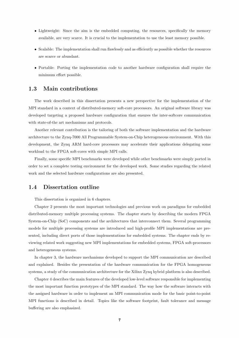
• Lightweight: Since the aim is the embedded computing, the resources, specifically the memory
available, are very scarce. It is crucial to the implementation to use the least memory possible.
• Scalable: The implementation shall run flawlessly and as efficiently as possible whether the resources
are scarce or abundant.
• Portable: Porting the implementation code to another hardware configuration shall require the
minimum effort possible.
1.3 Main contributions
The work described in this dissertation presents a new perspective for the implementation of the
MPI standard in a context of distributed-memory soft-core processors. An original software library was
developed targeting a proposed hardware configuration that ensures the inter-softcore communication
with state-of-the art mechanisms and protocols.
Another relevant contribution is the tailoring of both the software implementation and the hardware
architecture to the Zynq-7000 All Programmable System-on-Chip heterogeneous environment. With this
development, the Zynq ARM hard-core processors may accelerate their applications delegating some
workload to the FPGA soft-cores with simple MPI calls.
Finally, some specific MPI benchmarks were developed while other benchmarks were simply ported in
order to set a complete testing environment for the developed work. Some studies regarding the related
work and the selected hardware configurations are also presented.
1.4 Dissertation outline
This dissertation is organized in 6 chapters.
Chapter 2 presents the most important technologies and previous work on paradigms for embedded
distributed-memory multiple processing systems. The chapter starts by describing the modern FPGA
System-on-Chip (SoC) components and the architectures that interconnect them. Several programming
models for multiple processing systems are introduced and high-profile MPI implementations are pre-
sented, including direct ports of those implementations for embedded systems. The chapter ends by re-
viewing related work suggesting new MPI implementations for embedded systems, FPGA soft-processors
and heterogeneous systems.
In chapter 3, the hardware mechanisms developed to support the MPI communication are described
and explained. Besides the presentation of the hardware communication for the FPGA homogeneous
systems, a study of the communication architecture for the Xilinx Zynq hybrid platform is also described.
Chapter 4 describes the main features of the developed low-level software responsible for implementing
the most important function prototypes of the MPI standard. The way how the software interacts with
the assigned hardware in order to implement an MPI communication mode for the basic point-to-point
MPI functions is described in detail. Topics like the software footprint, fault tolerance and message
buffering are also emphasized.
7

Chapter 5 presents the evaluation results of the MPI application benchmarks executing on a Zynq
device. The system setup and the developed (or ported) MPI algorithms are also analyzed and explained
in detail. Specific algorithms for the Zynq heterogeneous system are finally developed and tested.
Chapter 6 introduces the main conclusions drawn from the developed work and suggests future solu-
tions to improve and complement both the MPI implementation and the benchmark algorithms.
8

2State-of-the-art
Contents2.1 FPGA SoC architectures . . . . . . . . . . . . . . . . . . . . . . . . . . . . . . 10
2.2 Parallel programming models . . . . . . . . . . . . . . . . . . . . . . . . . . . 11
2.3 MPI implementations . . . . . . . . . . . . . . . . . . . . . . . . . . . . . . . . 12
2.4 MPI implementations for Embedded Systems . . . . . . . . . . . . . . . . . 14
2.5 Conclusions . . . . . . . . . . . . . . . . . . . . . . . . . . . . . . . . . . . . . . 16
9

The overview of the different works previously developed in this area is an important part of this dis-
sertation since it contextualizes the problems to be solved and provides points of comparison. Therefore,
this chapter reviews state-of-the-art topics related with both the hardware and software environments to
implement parallel computing libraries.
Since the development of an MPI implementation on a FPGA-based heterogeneous system is one
of the main focus of this dissertation, specific architectures are summarily described. Afterwards, this
chapter describes and compares the different parallel programming models that accelerate the execution of
algorithms on distributed-memory processors. The final sections of this state-of-the-art chapter describe
and analyze different MPI implementations. The related work, where embedded systems and FPGA
oriented implementations are overviewed, is emphasized.
2.1 FPGA SoC architectures
Presently, SoCs containing the programmable logic of an FPGA device are regarded as versatile solu-
tions commercialized by the biggest FPGA manufacturers. These systems are the ideal environment for
the development of integrated heterogeneous solutions where dedicated hardware interacts with different
reconfigurable components. In fact, these FPGA Systems on Chip extend the intrinsic hardware devel-
opment and testing advantages provided by the FPGA devices with the availability on a single chip of a
wide range of peripherals and powerful Application Specific Integrated Circuit (ASIC) general purpose
processing units.
The leading FPGA manufacturers Xilinx and Altera have already made available different FPGA
SoC solutions for different requirements. While Altera included SoCs in the Arria 10 and Stratix 10
families, Xilinx created a new family exclusively dedicated to SoCs called Zynq All Programmable SoC.
There are 3 series within the Zynq family: the basic Zynq-7000 and the more powerful Zynq-UltraScale
and Zynq-UltraScale+. Though the Zynq UltraScale and UltraScale+ series provide more features and
better specifications (improved processing units and internal memories, addition of a Graphics Processing
Unit (GPU), more logic cells, BRAMs or DSP slices), the fundamental components of the integrated
architecture are the same from the Zynq-7000 series.
In this context, the concepts of Processing System (PS) and Programmable Logic (PL) are crucial.
The PS, or hard side, is a set of components that make up a modern and efficient embedded system:
low-power Processing Units, On-Chip Memories (OCMs), Memory Controllers, peripherals and System
Interconnects. The PL, or soft side, extends the PS side with reconfigurable logic cells, Block Random
Access Memories (BRAMs) and programmable Digital Signal Processing (DSP) units. Specifically, the
Zynq-7000 family provides a heterogeneous environment where the FPGA programmable logic (similar
to either Artix-7 or Kintex-7 depending from the model) is connected to an ARM Cortex-A9 MPCore
based processing system. The processing system’s side contains the ARM processor and several interfaces
(Gigabit Ethernet, UART, I2C, SPI and GPIO are some examples) to allow the compatibility with a vast
number of peripherals.
The efficient access from the soft side to the Processing System’s peripherals and memories - like
the Double Data Rate (DDR) memories - as well as the efficient access from the Processing System’s
10

side to the soft components is a main concern in these systems. To solve efficiently these data transfer
requirements, the Zynq-7000 SoC provides 3 main types of Advanced eXtensible Interface (AXI) ports
to allow the PS-PL communication:
• General Purpose (GP) - These general purpose ports are used when the Programmable Logic side
accesses the peripherals and/or small amounts of memory data available on the Processing System
and also when the PS application wants to read and store BRAM data. To achieve both purposes,
the Zynq PS side contains both GP Master and Slave interfaces.
• High-Performance Ports (HP) - These high bandwidth PL master ports are the ideal interfaces to
access to large amounts of data stored in the PS memories. Each port allows buffering, containing
two First In, First Out (FIFO) buffers. The number of HP ports available is also an important
factor. In fact, the greater the number of HP ports used, more efficient the data transfer is. The
Zynq-7000 systems contain 4 HP Ports.
• Accelerator Coherency Port (ACP) - This single PL master port is used to access to the PS memories
data. Unlike the HP ports, the ACP can work with the system’s memory caches. Using this port
along with the HP ports decreases the communication overhead [6].
Figure 2.1: General Xilinx Zynq-7000 architecture. Source: Xilinx [7]
After finding the right solution to implement the architectural PS-PL communication, the project
development flow of these systems is very similar to the flow of the other embedded systems.
2.2 Parallel programming models
Since the stagnation of the development of single-core processing units, several solutions and architec-
tures have been suggested in order to take advantage of the constant increase in the number of transistors
11
with the new technology improvements. The majority of these solutions focused on suggesting different
ways to exploit computational parallelism. While the instruction level parallelism (verified in the modern
superscalar processors or in Very Long Instruction Word processors like the Intel Itanium) was a first
response, the many-core/many-computer hardware parallelism has been the most discussed trend in this
context over the past years. Since this type of parallelism has been highly adopted and developed, mul-
tiple programming models were proposed in order to give to the software developer the flexibility to plan
the parallelization of his application.
Over the years some parallel programming model approaches like intelligent compilers that would
automatically convert the serial code to parallel versions or entirely-new parallel programming languages
(like the Occam language) have been discussed. Notwithstanding these solutions, the most popular
programming model implementations consist in new libraries or extensions of the already established
programming languages. Each implementation is usually more adapted to a specific hardware communi-
cation structure. In fact, the programming extension used for multiple core processing units with a shared
memory (used to store the entire internal code data of all the processors) is usually different from the
library used to parallelize algorithms on processing units with local memories (the architecture in study
to this work). As an example, the OpenMP extension has been a widely adopted solution for shared
memory multi-cores, but is not an option for distributed memory processing systems. There are also pro-
gramming extensions that consist in libraries that allow the processing units to delegate computational
workload of general propose applications to GPUs. This approach (known as GPGPU programming)
allowed the acceleration in large scale of some usual CPU-oriented applications. The versatile OpenCL
implementation and Nvidia’s CUDA are examples of extensions that allowed this type of computational
acceleration.
For distributed memory systems, some programming model solutions are possible. On one hand the
OpenCL can be also used for multiple Central Processing Unit (CPU) parallelization, on the other hand
more specific tools such as MPI implementations or the Parallel Virtual Machine (PVM) are widely
adopted for this purpose. The PVM aims to simulate an environment of a distributed operating system
allowing an explicit control of resources and favoring software portability. Other examples of middleware
designed for distributed systems are the CORBA architecture or the JAVA/RMI that feature remote
high-level procedure invocations for nodes on homogeneous or heterogeneous clusters. The MPI stan-
dard, in turn, does not pretend to implement a virtual operating system, is performance-oriented and
provides a richer system of message-passing. Compared with the other programming models, the MPI
programming for inter-processor data transfer is, in fact, much more explicit providing more versatility
but also demanding a more detailed approach by the application developer. Despite all the referred
solutions being valid, the MPI standard has been the most used parallel programming model for the
high-performance computing systems with distributed memory in the past years.
2.3 MPI implementations
Several implementations and extensions have been proposed since the launch of the first MPI-1.0
reference document describing the MPI interface. Over the years, open-source implementations like FT-
12
MPI [8], LAM/MPI, PACX-MPI, or MPICH[9] were widely used. More recently, the developers of some
of those implementations joined efforts to present an open-source definitive version compatible with the
latest MPI extension (MPI-3) and capable of ensuring good performances on different environments of
parallel computing. This implementation was named Open MPI and has been one of the most adopted
MPI implementations over the last few years [10].
The MPI implementations are not restricted to open-source distributions. As a matter of fact, com-
panies like Microsoft, IBM and Intel released their proprietary implementations: MS-MPI, Platform MPI
and IntelMPI, respectively. While Intel refers that the IntelMPI Library 5.1 may achieve speedups of 5.2
over Open MPI 1.8.5 on 64 nodes [11], IBM claims that the Platform MPI achieves better performance
than both OpenMPI and IntelMPI (as shown by the IBM tests performed with 8 processing nodes [12]).
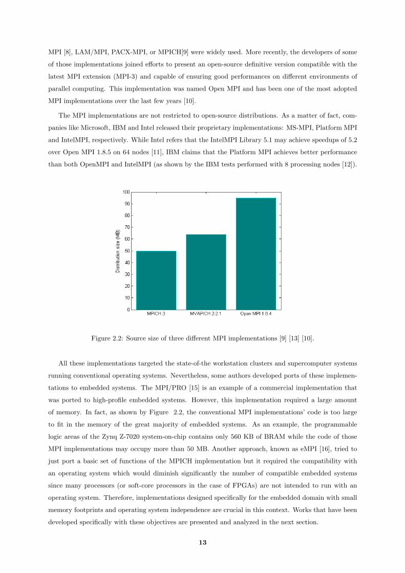
Figure 2.2: Source size of three different MPI implementations [9] [13] [10].
All these implementations targeted the state-of-the workstation clusters and supercomputer systems
running conventional operating systems. Nevertheless, some authors developed ports of these implemen-
tations to embedded systems. The MPI/PRO [15] is an example of a commercial implementation that
was ported to high-profile embedded systems. However, this implementation required a large amount
of memory. In fact, as shown by Figure 2.2, the conventional MPI implementations’ code is too large
to fit in the memory of the great majority of embedded systems. As an example, the programmable
logic areas of the Zynq Z-7020 system-on-chip contains only 560 KB of BRAM while the code of those
MPI implementations may occupy more than 50 MB. Another approach, known as eMPI [16], tried to
just port a basic set of functions of the MPICH implementation but it required the compatibility with
an operating system which would diminish significantly the number of compatible embedded systems
since many processors (or soft-core processors in the case of FPGAs) are not intended to run with an
operating system. Therefore, implementations designed specifically for the embedded domain with small
memory footprints and operating system independence are crucial in this context. Works that have been
developed specifically with these objectives are presented and analyzed in the next section.
13

2.4 MPI implementations for Embedded Systems
Though some solutions to directly port the supercomputing-oriented MPI implementations to embed-
ded systems have been discussed in the previous section, the main focus of this work is to research and
develop new basic-set MPI implementations targeting the embedded systems and, specifically, FPGA
devices. In the context of embedded systems it’s relevant to refer that some implementations for specific
digital electronic systems, like the MPI implementation for the Single Chip Message Passing (SCMP)
Multiprocessor [17], were successfully implemented. Using a synchronous communication mode, this
SCMP implementation provided compatibility with both synchronous and asynchronous point-to-point
functions and also with the major collective primitives (like the MPI Barrier or the MPI Bcast). As a
benchmark, the QR decomposition algorithm was tested and, while the MPI implementation achieved
some speedups (maximum value of 9 with a set of 30 processors), the native SCMP system achieved
considerable better performances in every dataset experimented.
Looking at the FPGA specific MPI implementations, the works presented in [18] and [19] are the
ones with the most similar objectives to the work presented in this dissertation. In [18], a reduced set of
the MPI standard is implemented for multiple MicroBlazes (Xilinx FPGA soft processors) connected to
each other through Fast Simplex Links (FSLs). The number of FSL interfaces in a Microblaze processor
is limited and, therefore, the system scalability is restricted to the maximum number of Microblaze
FSL interfaces (8 by the time this implementation was developed, 16 in the most recent MicroBlaze
versions). Considering that two FIFOs are required for each pair of linked Microblazes and defining NP
as the number of Microblaze processors in the architecture, the number of required FIFOs for the MPI
communication structure, NFIFOs, is given by:
NFIFOs = NP × (NP − 1) (2.1)
A design with 16 processors would, therefore, require 240 FIFOs. The subset of implemented functions
included the point-to-point MPI Send, MPI Recv and MPI Sendrecv (transmission and reception of data
in only one call) and the collective MPI Bcast, MPI Barrier and MPI Reduce functions. The authors
tested this implementation and architecture with the application cpi (pi calculus) from the MPICH2
library examples. A speedup of 8 with 8 processing units was achieved using this benchmark (where the
MPI communication per computation ratio is very small). Subsequent work from these authors used the
MPI implementation to successfully accelerate image processing applications [20].
In [19], an MPI implementation was developed for multiple FPGA devices interconnected through
Multi-Gigabit Transceivers (MGTs). Point-to-point functions with a synchronous communication mode
were developed. The collective functions (MPI Bcast, MPI Reduce, MPI Gather and MPI Barrier) were
implemented over the point-to-point functions in a layered fashion. To benchmark their work, the authors
implemented the Jacobi algorithm to solve the heat equation using a group of both Microblaze and
PowerPC405 processors (in total, 45 processors in 5 FPGAs with each device containing 7 Microblazes
and 2 PowerPCs). 100% efficiency is achieved up to 10 processors while the maximum speedup obtained is
around 27 using 40 processors. The authors justify the loss of performance with the limitations of resources
of the FPGA device they used (Xilinx XC2VP100). This implementation lacked the transmission of data
14
with words larger than 4 bytes and a buffered communication mode since the synchronous mode implies
extra overhead for each data transfer with the “request to send/ clear to send” hand-shaking packets.
Over the years, the authors from [19] focused on heterogeneous systems where the FPGA soft-
processors and specific hardware engines are able to communicate with x86 hard core processors through
MPI messages sent to a shared memory accessed via Intel FSB bus [21]. This time, the programmable
hardware configuration was implemented on the more recent Xilinx Virtex-5 devices. Other upgrades
consisted in the development of profiling tools to ease the evaluation of the implementation, implement-
ing new collective primitives (MPI Waitall and MPI Allreduce), adding a Direct Memory Access (DMA)
component to automate the access to the shared memory and allowing the compatibility with the asyn-
chronous point-to-point communication functions (although the syntax has some differences from the
standard) [22]. Dedicated hardware implementations for the collective MPI Bcast and MPI Reduce func-
tions were also added [23]. All these improvements made this MPI proposal in a complete and efficient
solution, however, all the intellectual property (IP) cores implemented and all the hardware used might
be too demanding for lower-cost FPGA systems.
Other works presented in [24], proposing specific hardware engines to accelerate the MPI Barrier
function, and in [25], suggesting a new data structure to store and search more efficiently the MPI
communication requests, are also important developments on this topic. In order to accelerate the
MPI Barrier execution, the authors from [24] focused on organizing the specific hardware engines (each
one associated with a soft-processor) in a tree structure. In this tree, the leaf nodes send a sync request to
their parents and these parents send, in turn, the request to their own parents until the request is received
by the root node. Then, the root note sends a ”clear” message to its children and all these children will also
send to their own children this ”clear” message. This process (inverse of the sync request) is perpetuated
until the tree’s leaf nodes receive that message. The authors tested the Balanced-Binomial tree, Binary
tree and Star topologies. Though the results are not disparate, the Balanced-Binomial tree was the
topology that achieved the best performance with the maximum number of nodes tested (32). This tree
network system can be easily tailored to implement other collective functions like the MPI Bcast.
Unlike the linear queues used to store the MPI communication requests (envelopes) in [19], the
memory structure proposed in [25] is a complex structure that targets efficient envelope search and
compare operations. In this structure, each cell (containing an MPI envelope) is added in the back of
the hardware structure and is removed (when it’s matched) in a linked list fashion. The matching is
associative, similar to the Ternary Content Addressable Memories (TCAMs). When a request to be
matched arrives in this structure, that request is compared in every cell in parallel. This first matching
step indicates in every cell if there was a match. The following step uses a tree of 2:1 multiplexers
to select the entry with a match, and, as second criterion, the first entry. This approach allows that,
when more than one match is performed (possible when multiple envelopes use the MPI ANY SOURCE
and MPI ANY TAG wildcards), the selected envelope is the first of the matched envelopes that arrived
in this structure, as the semantics described by the MPI-Forum say. Each soft-processor needs two of
these structures where each one needs 3 FIFOs plus the memories to store the own cells. This structure
may be useful when the list of cells to be matched is long enough to consider the compare and search
15

process a significant overhead. Finally, the authors used this architecture to support the implementation
of the synchronous and asynchronous MPI point-to-point and collective (MPI Bcast and MPI Waitall)
functions.
Table 2.1 summarizes the MPI functions developed in each implementation presented in this section.
Table 2.1: Function subsets of the reviewed embedded MPI implementations.
WorkTargetDevices
Session setupand inquiryfunctions
Point-to-pointfunctions
Collectivefunctions
Otherfunctions
[17] SCMP
MPI InitMPI Comm sizeMPI Comm rank
MPI Finalize
MPI SendMPI RecvMPI IsendMPI Irecv
MPI BcastMPI ReduceMPI BarrierMPI GatherMPI Scatter
MPI Reduce scatter
MPI WaitMPI Comm createMPI Comm dupMPI Comm split
[18] FPGAs
MPI InitMPI Comm sizeMPI Comm rank
MPI Finalize
MPI SendMPI Recv
MPI Sendrecv
MPI BcastMPI ReduceMPI Barrier
-
[19]FPGA
Clusters
MPI InitMPI Comm sizeMPI Comm rank
MPI Finalize
MPI SendMPI Recv
MPI BcastMPI ReduceMPI Barrier,MPI Gather
MPI Wtime
[21]FPGA +x86 CPUsClusters
MPI InitMPI Comm sizeMPI Comm rank
MPI Finalize
MPI SendMPI RecvMPI IsendMPI Irecv
MPI BcastMPI ReduceMPI BarrierMPI GatherMPI Waitall
MPI Allreduce
MPI WtimeMPI WaitMPI Test
[25] FPGAs
MPI InitMPI Comm sizeMPI Comm rank
MPI Finalize
MPI SendMPI RecvMPI IsendMPI Irecv
MPI BarrierMPI Waitall
MPI Wait
2.5 Conclusions
This chapter started by presenting the actual context of the FPGA Systems on Chip. Emphasis has
been given to the Xilinx Zynq-7000 architecture since Zynq-7000 devices are used as the testbed for this
work. The different solutions (GP, ACP or HP ports) to connect the FPGA logic to the hard processing
system were described in some detail in this context.
In the second section, different paradigms for High-Performance parallel computing were introduced.
Distributed-memory oriented programming models like the PVM and the CORBA environments were
described but it was concluded that the MPI programming model was the most suitable interface taking
into account this dissertation objectives.
Different high-profile MPI implementations were also overviewed. The tailoring of these implemen-
tations to embedded systems was considered very restrictive since those implementations require a large
amount of memory and rely on operating systems. Some relevant related works that propose specific
MPI implementations for embedded systems instead of trying to port directly the mainframe cluster
16

implementations are finally discussed. In order to collect terms of comparison for the new approach pre-
sented in this document, the efficiency of those state-of-the art FPGA and embedded implementations
was presented and their scalability (in terms of logic cells and memory) was discussed.
In addition of validating the Zynq systems as a viable environment to design and test heterogeneous
architectures and considering the MPI as the most appropriate programming model to be implemented,
the research work presented in this chapter suggests that the communication architecture shall be as
simple and scalable as possible to primarily support the point-to-point communication functions. It can
also be concluded that most used collective functions (MPI Bcast, MPI Barrier and MPI Reduce) shall
be implemented either by calling the point-to-point functions or by taking advantage of the hardware
structure defined for the point-to-point communication. These reviewed approaches are in accordance
with the low resource utilization objectives previously defined and, therefore, will be taken into account
in the following chapters.
17

18
3Hardware architectures
Contents3.1 FPGA homogeneous system . . . . . . . . . . . . . . . . . . . . . . . . . . . . 20
3.1.1 FPGA softprocessor . . . . . . . . . . . . . . . . . . . . . . . . . . . . . . . . . 20
3.1.2 Multi-processing architecture . . . . . . . . . . . . . . . . . . . . . . . . . . . . 21
3.2 Heterogeneous system . . . . . . . . . . . . . . . . . . . . . . . . . . . . . . . 24
3.2.1 Communication ports and memories . . . . . . . . . . . . . . . . . . . . . . . . 24
3.2.2 Multi-processing Architecture . . . . . . . . . . . . . . . . . . . . . . . . . . . . 26
3.3 Conclusions . . . . . . . . . . . . . . . . . . . . . . . . . . . . . . . . . . . . . . 29
19
This chapter presents the hardware multi-processor architectures developed to support the imple-
mentation of an MPI standard. First, an homogeneous architecture based on a FPGA soft-processor is
discussed and proposed. Then, an heterogeneous architecture is proposed that adds support for the inclu-
sion of FPGA hard-processors for both FPGA soft-processor architectures and heterogeneous (soft and
hard core processors) systems. The development of these parallel computing architectures took into con-
sideration the (already listed) requirements for the software implementation, especially, the requirements
related with resource efficiency.
This chapter also describes the soft-processor to be used and the hardware mechanisms and protocols
that provide the communication between hard and soft processing units. The architecture implementation
targeted the Zynq-7000 All Programmable SoCs device family and all design development was done with
the aid of the Vivado 2014.4 design environment. Although most decision decisions envisaged system
portability, a few options had to consider specifics of the target platform.
3.1 FPGA homogeneous system
In order to develop an MPI software library for FPGA soft processors, it’s fundamental to, firstly,
define and study the multi-processing architectures that meet the stipulated objectives for execution of the
parallel applications. This section describes the proposed multi-processor architecture based on a general
purpose soft-processor. Emphasis is given to the important topic of the support for MPI communication
between processsors, which is one of the main contributions of this dissertation.
3.1.1 FPGA softprocessor
Several soft-processing systems, both proprietary and open-source, are currently available. Consider-
ing that the target device is a Xilinx Zynq SoC FPGA, using a Xilinx soft-processor, has the significant
advantages of full support on the design environment and easy integration of the software and hardware
components. In fact, using Xilinx soft-processors on a Xilinx development environment means full sup-
port and easy integration of the soft configurations and peripherals. Xilinx provides two soft-processor
systems which main features are shown in Table 3.1. However, the PicoBlaze is a simple 8-bit micro-
controller without a full software programming environment using a high-level language, such as C. In
turn, the MicroBlaze can be programmed in C (using the MB-GCC tool chain) and is still a light core,
with the basic configuration occupying less than 1500 Look Up Tables (LUTs) (the lowest complexity
Zynq device, Z-7010, contains 17600 LUTs). The MicroBlaze soft-processor also provides efficient AXI
interfaces: AXI-Stream (for non-addressable data transfers), AXI-4 Full (for addressable data-transfers
with support for bursts) and AXI-4 Lite (for addressable non-burst data transfers).
Table 3.1: Xilinx soft-processors comparison [30] [27].Soft-processor Architecture Pipelining Bus Interfaces Programming
PicoBlaze 8-bit - - AssemblyMicroBlaze 32-bit RISC 5 stages LMB, AXI C
Open-source soft-core processors with similar architectures to MicroBlaze are also available and are
20

overviewed in Table 3.2. However, there is no major argument to justify the selection of an open-source
soft processor in this case. The fact that the related work analyzed is all based on MicroBlaze soft
processors also helped in this decision.
Table 3.2: 32-bit RISC soft-processors comparison [28] [29] [30] [31] [32] [2].Soft-processor fMAX(MHz) Pipelining LUTs Bus Interfaces Programming
MicroBlaze 200 5 stages 1324 LMB, AXI CLatticeMico32 115 6 stages 2370 Wishbone C
LEON 3 183 7 stages 4581 AMBA 2.0 CMB-LITE 229 5 stages 1450 Wishbone C
OpenRISC 1200 185 5 stages 5379 Wishbone COpenFIRE 198 3 stages 959 OPB, FSL C
3.1.2 Multi-processing architecture
The architecture proposed to link all the processors is based on a memory, used exclusively for the
MPI communications and accessed by all processors.
Other architectures, different from this MPI memory solution, were also studied. A system where
all the processors were linked through AXI-Streams was primarily considered. In this case, the num-
ber of memory resources needed was considered too high, as discussed in the state-of-the-art chapter.
The high resource requirements are also evident in architectures that use a memory (exclusive for MPI
communications) per processor.
A specific hardware engine, intended to work along with the proposed MPI memory architecture,
was also analysed. This engine had the objective of providing an efficient structure to support the
asynchronous point-to-point communication functions (MPI Isend and MPI Irecv). Therefore, the engine
would be responsible to autonomously read and store envelope values from/to the MPI memory and
compare those values in order to detect an envelope match. Each soft-processor would have one of
these cores linked through AXI-Stream in order to send the asynchronous envelope requests and receive
the status information of the envelope matching. All the cores would also had to be masters of the
MPI memory. Besides the logic and registers required to access and compare the MPI memory data,
each engine would require one FIFO to store all the multiple asynchronous envelope requests and another
FIFO to store the matching status of each one of the requests. This structure would be particularly useful
in cases where the processors are able to execute some computational work while the matching of previous
MPI communication requests is yet to be done. However, in the majority of the parallel applications,
the computational work is usually dependent from the previous data transfers and, therefore, it was
considered that the additional complexity that these cores bring would not be worthwhile.
The communication between the MicroBlazes and the MPI memory is automatically handled by the
AXI Interconnect. This MPI memory is connected to the Microblazes using the AXI4-Lite.
This memory architecture only needs 1 memory element to implement the communication structure
of a fully working MPI library. Nonetheless, the architecture may have a disadvantage in some cases.
This disadvantage is related with the contention eventually verified on the Interconnect when several
soft-processors try to access to a considerable amount of memory data.
21
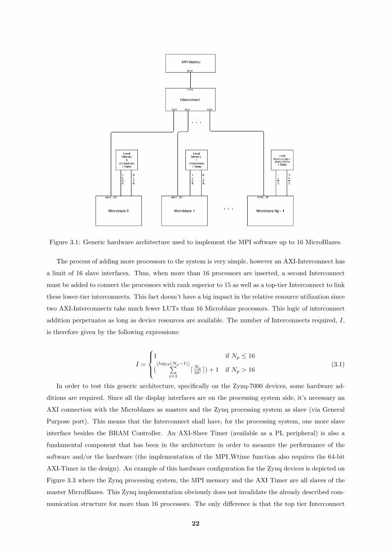
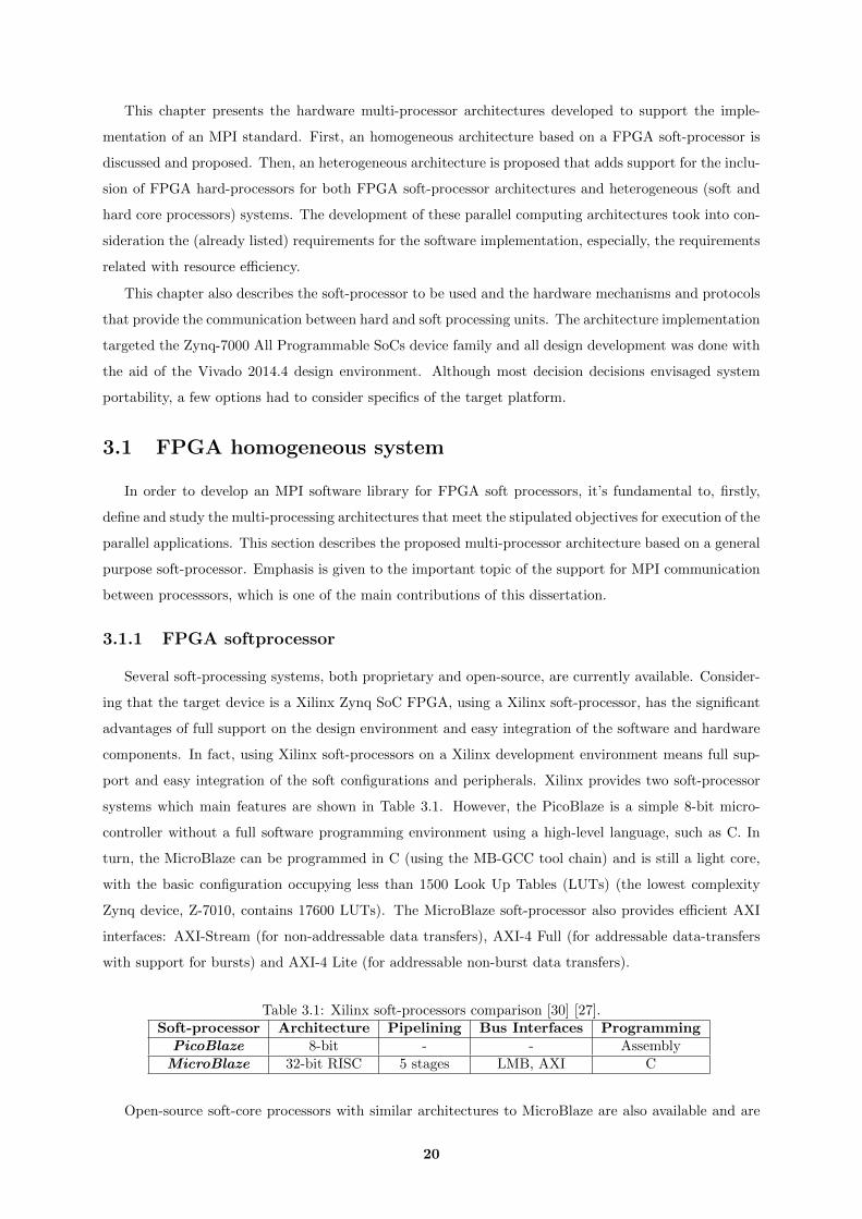
Figure 3.1: Generic hardware architecture used to implement the MPI software up to 16 MicroBlazes.
The process of adding more processors to the system is very simple, however an AXI-Interconnect has
a limit of 16 slave interfaces. Thus, when more than 16 processors are inserted, a second Interconnect
must be added to connect the processors with rank superior to 15 as well as a top-tier Interconnect to link
these lower-tier interconnects. This fact doesn’t have a big impact in the relative resource utilization since
two AXI-Interconnects take much fewer LUTs than 16 Microblaze processors. This logic of interconnect
addition perpetuates as long as device resources are available. The number of Interconnects required, I,
is therefore given by the following expressions:
I =
1 if Np ≤ 16
(blog16(Np−1)c∑
i=1
dNp
16i e) + 1 if Np > 16(3.1)
In order to test this generic architecture, specifically on the Zynq-7000 devices, some hardware ad-
ditions are required. Since all the display interfaces are on the processing system side, it’s necessary an
AXI connection with the Microblazes as masters and the Zynq processing system as slave (via General
Purpose port). This means that the Interconnect shall have, for the processing system, one more slave
interface besides the BRAM Controller. An AXI-Slave Timer (available as a PL peripheral) is also a
fundamental component that has been in the architecture in order to measure the performance of the
software and/or the hardware (the implementation of the MPI Wtime function also requires the 64-bit
AXI-Timer in the design). An example of this hardware configuration for the Zynq devices is depicted on
Figure 3.3 where the Zynq processing system, the MPI memory and the AXI Timer are all slaves of the
master MicroBlazes. This Zynq implementation obviously does not invalidate the already described com-
munication structure for more than 16 processors. The only difference is that the top tier Interconnect
22
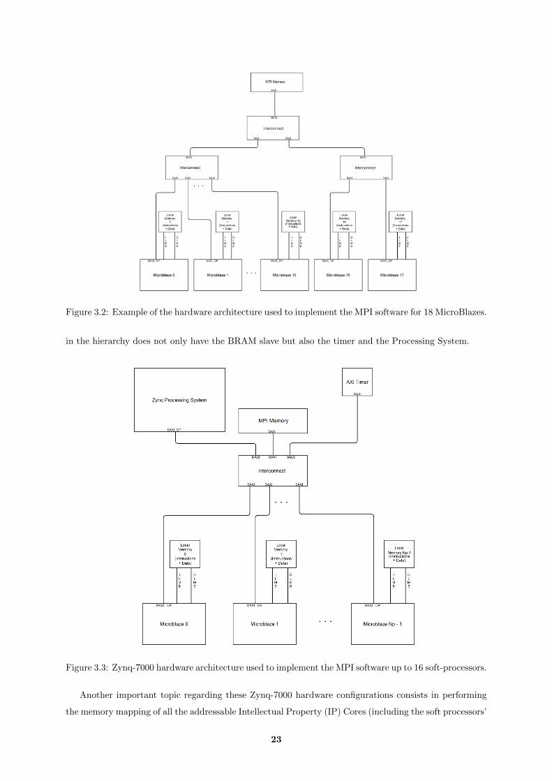
Figure 3.2: Example of the hardware architecture used to implement the MPI software for 18 MicroBlazes.
in the hierarchy does not only have the BRAM slave but also the timer and the Processing System.
Figure 3.3: Zynq-7000 hardware architecture used to implement the MPI software up to 16 soft-processors.
Another important topic regarding these Zynq-7000 hardware configurations consists in performing
the memory mapping of all the addressable Intellectual Property (IP) Cores (including the soft processors’
23

local memory for data and instructions) and Processing System’s components. To cover this task, the
Xilinx Vivado software provides an Address Editor wizard to allow the hardware developer to map the
addresses of the components. This mapping may be manual or automatic using the corresponding “Auto-
assign addresses” option. For this FPGA homogeneous configuration, the Xilinx automatic mapping was
selected. The hardware synthesis, implementation and bitstream generation phases worked as expected
(with no errors nor critical warnings) using this type of software mapping. However, other configurations,
like the following heterogeneous system architecture, require a manual mapping. This address mapping
question, as well as other different features related with the hardware configuration defined to implement
a Zynq heterogeneous system, is precisely the focus of the next section of this document.
3.2 Heterogeneous system
The development of an MPI communication structure for a heterogeneous system, that also included
the ARM processors, was considered an additional objective of this work since the chosen development
devices are the heterogeneous Xilinx Zynq-7000 SoCs.
Regarding the programmable logic’s side, this configuration for heterogeneous systems preserves the
main features described in the previous section of the homogeneous architecture. The target soft-
processors are the MicroBlaze CPUs and the basic programmable logic communication architecture
consists in using an AXI-Interconnect to connect all the soft-processors to a memory.
However, the presence of the dual core ARM processor and the communication between the hard ARM
cores side and the FPGA programmable logic side must be considered. The communication MicroBlaze-
to-MicroBlaze is no longer the only communication type present in the system and, in this case, there
are 3 inter-processor communication types that must be implemented:
• MicroBlaze to MicroBlaze communication
• ARM Core to ARM Core communication
• MicroBlaze to ARM Core and ARM Core to MicroBlaze communication
While the implementation of the first point was already described, the last two points require a
detailed analysis in order to obtain the most efficient architecture. The following sections study and
evaluate the possible communication combinations and propose a hardware structure to implement this
heterogeneous system.
3.2.1 Communication ports and memories
This section analyzes the different possibilities to successfully connect the Programmable Logic soft-
processors and the ARM cores. The Zynq devices used in this work contain in the processing system’s
side a controller interface to an external DDR Random Access Memory (RAM) memory. This memory
and the Programmable Logic’s BRAM memory are all viable links for the heterogeneous communication.
The Zynq devices provide 3 different ports (AXI GP, ACP and HP) to allow communication between the
PS and PL sides. A number of “memory + port” combinations were implemented and tested in order
24

to experimentally conclude about the feasibility and efficiency of the solution. These combinations are
resumed in Table 3.3
Table 3.3: Possible combinations for the MicroBlaze-to-ARM memory communication.Configuration MPI Memory PL-Memory Port ARM-Memory Port
1 DDR HP PS Internal2 DDR ACP PS Internal3 DDR GP PS Internal4 BRAM PL Internal GP
All the combinations referred in Table 3.3 were tested. However, due to cache coherence issues, the
ARM cores only read successfully what the MicroBlazes wrote on the DDR when the ARM caches were
disabled or invalidated.
In order to select the appropriate configuration, a simple application for the ARM cores was developed.
In this application, the ARM core reads 250 memory positions and stores those values in an array of
floats. For the accessed memory in this application, both the BRAM (through the AXI-4 GP port) and
the DDR were tested but the cache was only enabled for the BRAM memory. The time was measured
with a PL AXI-Timer (connected to the Processing System block using the same AXI-4 GP port). The
defined clock frequency on the Programmable Logic was 100 MHz (this value was considered appropriate
for every PL design in this work taking into account that the multi-processing designs use MicroBlazes).
The results obtained are presented in Table 3.4
Table 3.4: Cycles spent with the ARM core accessing and storing 250 floating-point memory valuesMPI Memory ARM Cache Execution Cycles
DDR Disabled 7095BRAM Enabled 5542BRAM Disabled 9067
The results obtained from this memory access test show that the communication via DDR with caches
disabled does not achieve better performance than using the BRAM memory from the Programmable
Logic (already used in the homogeneous system).
There were other factors that helped in this decision of selecting the BRAM as the channel of com-
munication to the two different sides of the Zynq hardware. The first reason consisted in the simplicity
of tailoring the homogeneous system software to this case and the other reason is the obvious reduced
memory access time from the MicroBlaze.
Taking into account the software structure and the communication mode described in the following
chapter, the memory size is not a crucial factor to the selection of this communication structure.
In order to conceive the implementation software as light as possible, the communication ARM-to-
ARM is also ensured using the BRAM memory. While other solutions described in Table 3.3 could be
more efficient for this case, the software implementation (prioritizing in first place the heterogeneous and
FPGA communication) wouldn’t be as simple and device transparent. Since the structure to implement all
the communication types is selected, the next section presents the detailed multi-processor architecture.
25
3.2.2 Multi-processing Architecture
Once defined the communication ports and memories that implement all the types of inter-processor
communications, the multi-processing architecture and the relevant Programmable Logic configurations
are presented in this section.
In first place, we look at the differences of the block organization between the FPGA homogeneous
system and the heterogeneous system, namely the questions regarding the Processing System components
and connections. In the homogeneous system’s case, the Processing System block was just an AXI slave to
provide interfaces to the Programmable Logic. Now the Processing System provides two general purpose
computing nodes, the dual-core ARM, while maintaining the previous interface-provider role. Therefore,
these cores must also act as Masters connected to the MPI memory (as discussed in the previous section)
and, eventually, to other PL peripherals, such as the timer.
Since the Processing System also provides Master AXI ports, the connection to the MPI memory
and other soft-peripherals through the AXI-Interconnect is viable. However, if the MicroBlaze processors
still want to access to some board interfaces with software support (i.e. not using the EMIO ports), the
processing system must be an AXI slave and master at the same time. Therefore, two Interconnects are
required in this case (considering that the number of MicroBlazes defined is less than 16): one where the
masters MicroBlazes access the slave Processing System and another where the masters Microblazes and
Processing System access the shared AXI slaves, such as the MPI memory and the timer.
Given the total number of MicroBlaze soft-processors in the entire system, NMB , the number of
required Interconnects, I, is now one more than in the homogeneous system. The new expressions are:
I =
2 if NMB ≤ 16
(blog16(NMB−1)c∑
i=1
dNMB
16i e) + 2 if NMB > 16(3.2)
The automatic device address mapping provided by the Vivado 2014.4 software did not assign as
desired the devices to the processors. Consequently, a manual device address mapping using the Xilinx
Address Editor must be performed for this heterogeneous configuration. The first rule followed, when
performing the manual address assignment, consisted in always defining the same offset address and range
values for a specific device, independently of the processing block where the device is assigned. This means
that all the AXI slaves common to the MicroBlazes and the Processing System have the same configuration
on every master. Secondly, the selection of the offset and range values for the Processing System segments
accessed by the MicroBlazes is not arbitrary. For instance, the offset address value 0xE0000000 with a
range of 4M is an assignment associated with the Processing System Input/Outuput (IO) control since
a range of PS peripherals are mapped in this way on the hard side. Yet, the PS segments that are not
used by the system may be unmapped.
Regarding the MicroBlaze local memories, the instructions segment assignment may overlap the data
26

Figure 3.4: Hardware architecture used to implement the MPI heterogeneous version up to 16 soft-processors.
segment assignment since the MicroBlaze memory organization follows an Harvard architecture, with
separate access and storage for data and instructions (although implemented in the same physical dual-
port RAM, as shown in Figure 3.5).
27
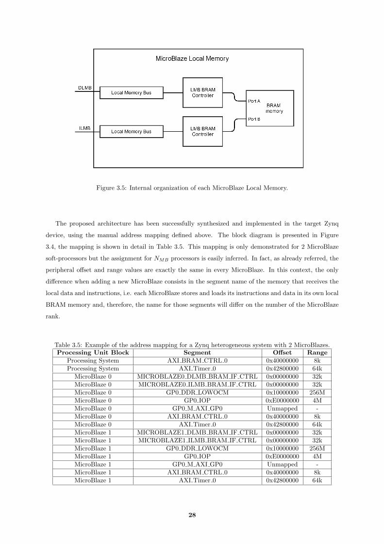
Figure 3.5: Internal organization of each MicroBlaze Local Memory.
The proposed architecture has been successfully synthesized and implemented in the target Zynq
device, using the manual address mapping defined above. The block diagram is presented in Figure
3.4, the mapping is shown in detail in Table 3.5. This mapping is only demonstrated for 2 MicroBlaze
soft-processors but the assignment for NMB processors is easily inferred. In fact, as already referred, the
peripheral offset and range values are exactly the same in every MicroBlaze. In this context, the only
difference when adding a new MicroBlaze consists in the segment name of the memory that receives the
local data and instructions, i.e. each MicroBlaze stores and loads its instructions and data in its own local
BRAM memory and, therefore, the name for those segments will differ on the number of the MicroBlaze
rank.
Table 3.5: Example of the address mapping for a Zynq heterogeneous system with 2 MicroBlazes.Processing Unit Block Segment Offset Range
Processing System AXI BRAM CTRL 0 0x40000000 8kProcessing System AXI Timer 0 0x42800000 64k
MicroBlaze 0 MICROBLAZE0 DLMB BRAM IF CTRL 0x00000000 32kMicroBlaze 0 MICROBLAZE0 ILMB BRAM IF CTRL 0x00000000 32kMicroBlaze 0 GP0 DDR LOWOCM 0x10000000 256MMicroBlaze 0 GP0 IOP 0xE0000000 4MMicroBlaze 0 GP0 M AXI GP0 Unmapped -MicroBlaze 0 AXI BRAM CTRL 0 0x40000000 8kMicroBlaze 0 AXI Timer 0 0x42800000 64kMicroBlaze 1 MICROBLAZE1 DLMB BRAM IF CTRL 0x00000000 32kMicroBlaze 1 MICROBLAZE1 ILMB BRAM IF CTRL 0x00000000 32kMicroBlaze 1 GP0 DDR LOWOCM 0x10000000 256MMicroBlaze 1 GP0 IOP 0xE0000000 4MMicroBlaze 1 GP0 M AXI GP0 Unmapped -MicroBlaze 1 AXI BRAM CTRL 0 0x40000000 8kMicroBlaze 1 AXI Timer 0 0x42800000 64k
28
3.3 Conclusions
This chapter proposed the multiprocessor architecture to support an MPI software library both on
FPGA homogeneous systems and on Xilinx Zynq heterogeneous systems.
The Xilinx MicroBlaze is the soft-processor used as the main computation node in this work. Then,
the AXI-4 and AXI-Stream protocols were briefly introduced and the considered structures to implement
the inter-processor communication were analyzed. The communication architecture is based on a memory
that is accessed by the processors via an AXI-Interconnect. This solution is very efficient in terms of
resource consumption, although eventual contention can arise at the interconnect in case of intensive
simultaneous communications by a large number of processors.
The same memory-based design proved to be the most adequate solution for the heterogeneous archi-
tecture, where communications are also possible between the ARM cores, and between the ARMs and
the MicroBlazes. The required communications between the Programmable Logic and the Processing
System are implemented through the AXI GP Master Port.
The two multi-processing architectures proposed in this chapter are reliable and efficient solutions
to support an MPI implementation. The way how the MPI software exploits these architectures to
implement each function of a fully-working MPI subset is the next step in this work.
29

30
4Software implementation
Contents4.1 Software organization . . . . . . . . . . . . . . . . . . . . . . . . . . . . . . . . 32
4.2 MPI communication mode and message buffering . . . . . . . . . . . . . . . 35
4.3 Implemented functions . . . . . . . . . . . . . . . . . . . . . . . . . . . . . . . 36
4.4 Error handling . . . . . . . . . . . . . . . . . . . . . . . . . . . . . . . . . . . . 41
4.5 Software footprint . . . . . . . . . . . . . . . . . . . . . . . . . . . . . . . . . . 42
4.6 Software compatibility with Heterogeneous system . . . . . . . . . . . . . . 43
4.7 Conclusions . . . . . . . . . . . . . . . . . . . . . . . . . . . . . . . . . . . . . . 44
31
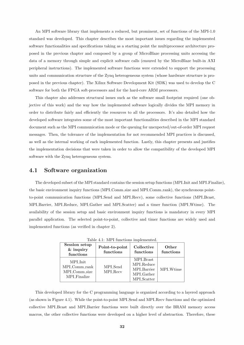
An MPI software library that implements a reduced, but prominent, set of functions of the MPI-1.0
standard was developed. This chapter describes the most important issues regarding the implemented
software functionalities and specifications taking as a starting point the multiprocessor architecture pro-
posed in the previous chapter and composed by a group of MicroBlaze processing units accessing the
data of a memory through simple and explicit software calls (ensured by the MicroBlaze built-in AXI
peripheral instructions). The implemented software functions were extended to support the processing
units and communication structure of the Zynq heterogeneous system (whose hardware structure is pro-
posed in the previous chapter). The Xilinx Software Development Kit (SDK) was used to develop the C
software for both the FPGA soft-processors and for the hard-core ARM processors.
This chapter also addresses structural issues such as the software small footprint required (one ob-
jective of this work) and the way how the implemented software logically divides the MPI memory in
order to distribute fairly and efficiently the resources to all the processors. It’s also detailed how the
developed software integrates some of the most important functionalities described in the MPI standard
document such as the MPI communication mode or the queuing for unexpected/out-of-order MPI request
messages. Then, the tolerance of the implementation for not recommended MPI practices is discussed,
as well as the internal working of each implemented function. Lastly, this chapter presents and justifies
the implementation decisions that were taken in order to allow the compatibility of the developed MPI
software with the Zynq heterogeneous system.
4.1 Software organization
The developed subset of the MPI standard contains the session setup functions (MPI Init and MPI Finalize),
the basic environment inquiry functions (MPI Comm size and MPI Comm rank), the synchronous point-
to-point communication functions (MPI Send and MPI Recv), some collective functions (MPI Bcast,
MPI Barrier, MPI Reduce, MPI Gather and MPI Scatter) and a timer function (MPI Wtime). The
availability of the session setup and basic environment inquiry functions is mandatory in every MPI
parallel application. The selected point-to-point, collective and timer functions are widely used and
implemented functions (as verified in chapter 2).
Table 4.1: MPI functions implemented.Session setup
& inquiryfunctions
Point-to-pointfunctions
Collectivefunctions
Otherfunctions
MPI InitMPI Comm rankMPI Comm size
MPI Finalize
MPI SendMPI Recv
MPI BcastMPI ReduceMPI BarrierMPI GatherMPI Scatter
MPI Wtime
This developed library for the C programming language is organized according to a layered approach
(as shown in Figure 4.1). While the point-to-point MPI Send and MPI Recv functions and the optimized
collective MPI Bcast and MPI Barrier functions were built directly over the BRAM memory access
macros, the other collective functions were developed on a higher level of abstraction. Therefore, these
32
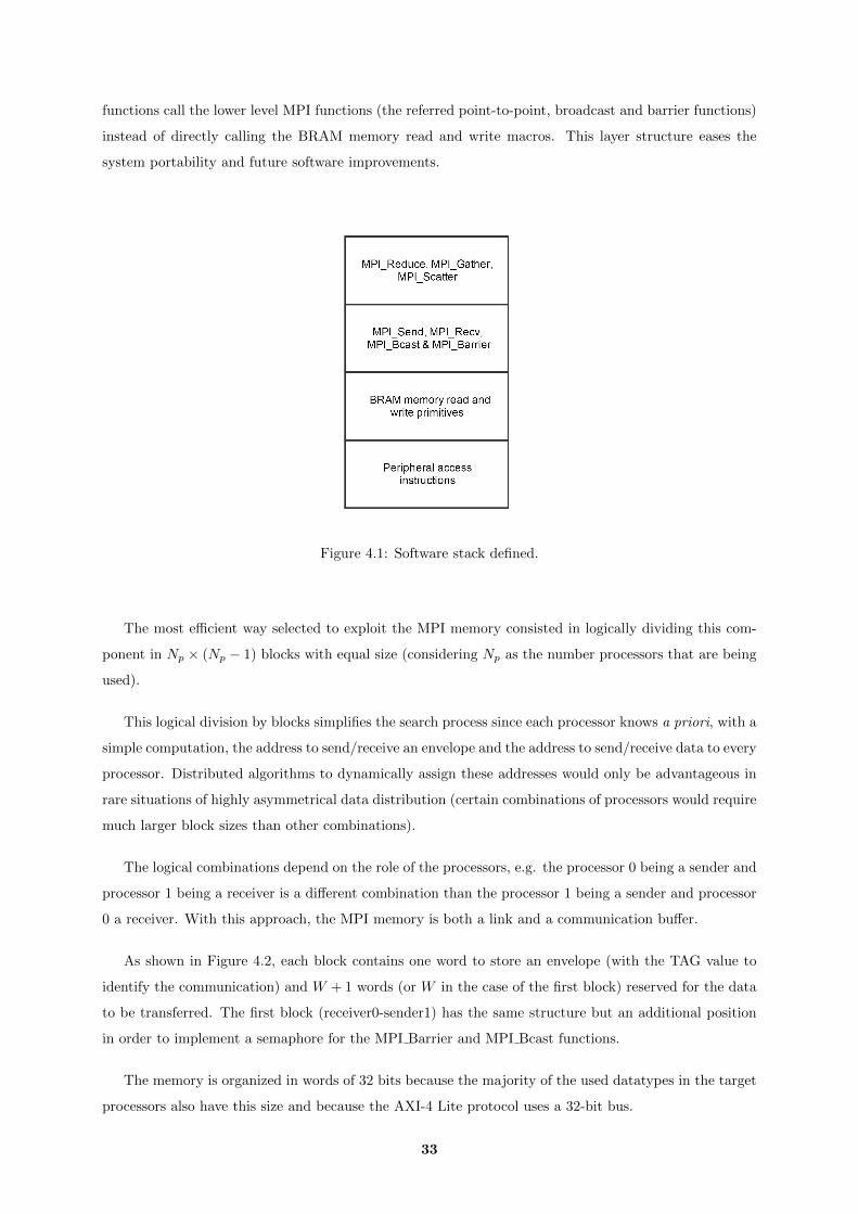
functions call the lower level MPI functions (the referred point-to-point, broadcast and barrier functions)
instead of directly calling the BRAM memory read and write macros. This layer structure eases the
system portability and future software improvements.
Figure 4.1: Software stack defined.
The most efficient way selected to exploit the MPI memory consisted in logically dividing this com-
ponent in Np × (Np − 1) blocks with equal size (considering Np as the number processors that are being
used).
This logical division by blocks simplifies the search process since each processor knows a priori, with a
simple computation, the address to send/receive an envelope and the address to send/receive data to every
processor. Distributed algorithms to dynamically assign these addresses would only be advantageous in
rare situations of highly asymmetrical data distribution (certain combinations of processors would require
much larger block sizes than other combinations).
The logical combinations depend on the role of the processors, e.g. the processor 0 being a sender and
processor 1 being a receiver is a different combination than the processor 1 being a sender and processor
0 a receiver. With this approach, the MPI memory is both a link and a communication buffer.
As shown in Figure 4.2, each block contains one word to store an envelope (with the TAG value to
identify the communication) and W + 1 words (or W in the case of the first block) reserved for the data
to be transferred. The first block (receiver0-sender1) has the same structure but an additional position
in order to implement a semaphore for the MPI Barrier and MPI Bcast functions.
The memory is organized in words of 32 bits because the majority of the used datatypes in the target
processors also have this size and because the AXI-4 Lite protocol uses a 32-bit bus.
33

Figure 4.2: Logical organization of the MPI memory.
As shown in Table 4.2, the long type, and, consequently, the equivalent MPI LONG, occupy only
4 bytes in Microblaze systems. Nonetheless, the MicroBlaze is compatible with the 8-byte datatypes
MPI LONG LONG and MPI DOUBLE. The proposed implementation was developed in order to be
compatible with both the 4-byte and 8-byte types described in Figure 4.2. The implemented solution for
the 8-byte data consisted in halving each 8-byte word in 2 memory data words (4-bytes), doubling the
34

number of data reads and stores when compared with the transmission of 4-byte datatypes.
Table 4.2: Size of the C datatypes compatible with the implementation in the MicroBlaze.C Datatype MPI equivalent MicroBlaze size
char MPI CHAR 1unsigned char MPI UNSIGNED CHAR 1
int MPI INT 4unsigned MPI UNSIGNED 4
short MPI SHORT 2unsigned short MPI UNSIGNED SHORT 2
long MPI LONG 4long long MPI LONG LONG 8
float MPI FLOAT 4double MPI DOUBLE 8
4.2 MPI communication mode and message buffering
The implementation of some of the most important recommendations of the MPI-Forum reference
document is discussed in this section. Considering the communication modes specified by the MPI-
Forum, the communication mode developed to this work may be considered a standard mode. In fact,
depending on the MPI memory situation, a sender processor may send data without waiting for the
receiver processor or just wait for some condition to start the data transfer. There are two conditions
that hold back the sender: firstly when the receiver did not read yet the latest data transmission; and
secondly, when the data to send is bigger than the block size (the sender processor must divide the data
in chunks and ensure that the latest chunk was already read before sending the next one).
The synchronous mode was not selected since it would always require that both processors would
send to the memory the “Request to send/ Clear to send” words even when the buffer is free. Moreover,
the processors may have slightly different computational tasks and may not need to be synchronized just
for one data transmission. A full buffered mode would not fulfill the scalability requirements (the MPI
memory would always have to be very large) and, even so, it would not be a safe practice since the data to
transmit may be always bigger than the MPI memory size. This suggested standard mode is, therefore,
a mid-point between the synchronous and the buffered mode taking into account the specific hardware
communication structure.
Since the data transmission is performed in chunks when the amount of data to be sent is bigger than
the assigned block size of the memory, the MPI memory size is not a crucial factor for the execution of
the application. In fact, all the positions for the envelopes and the barrier rendezvous must be ensured
but the space for the data transfer (the most considerable part of the memory size) may be arbitrary.
Nonetheless, there are situations where using a larger MPI memory will slightly improve the performance
of the parallel implementation. These cases occur when the message-passing applications follow the most
common paradigm of workload distribution, i.e., there is a sender processor that distributes the entire
workload to all the other processors. Let’s also consider that the workload transmitted at one time to
each processor is too large and, thus, must be divided in chunks. Since the sender processor (the one
that distributes the workload) must wait for the successful reception of the previous data chunks in each
35
transmission, all the other processors that did not receive yet its workload must also wait this additional
time. Moreover, the process of dividing and transmitting the data in chunks is also an overhead to
take into account. Increasing the MPI memory size would lead to fewer data chunks and, therefore, less
overhead transmission time.
On the other hand, the most evident case of applications not taking advantage of the size of the
MPI memory occurs when unsynchronized processors communicate using several point-to-point function
calls to transmit small portions of data. In fact, if the sender processor reaches a MPI Send primitive
to a certain processor when the previous transmission to the same processor was not acknowledged yet,
the application may be some time blocked because the communication mode requires a confirmation
of the success of the previous transmission, whether the size of the memory is large or not. To study
this situation, a communication mode was implemented that made the sender processor only wait for the
receiver when, actually, there is no space to store the desired data message. However, that implementation
required much more memory accesses and computational work. In fact, this solution would require that
a sender processor would have to perform, at least, one loop accessing the block positions in order to
determine whether there is sufficient space at the block to store the desired data. In addition, the size
for data transfer would decrease since many memory positions would be used to indicate the status of
those data transfer words. Taking also into account that the improvements would only be used on very
specific cases, that communication mode was discarded.
It’s important to note that this implementation is not compatible with the wildcards MPI ANY TAG
and MPI ANY SOURCE since the polling routines would take a considerable amount of code space
when the wildcards may be easily adapted to concrete processor ranks by the MPI developer. The only
communicator compatible is the MPI COMM WORLD since it makes no difference for an MPI user
unless he calls parallel libraries that also use MPI (which is unlikely considering that the target platforms
are embedded computing systems).
In the MPI specification documents, the MPI-Forum also emphasizes the need of queues to buffer
MPI requests that arrive out of order or unexpectedly. In this case, all the required message buffering
is already ensured taking into account the hardware structure and the communication mode developed.
In fact, if a processor is waiting for an envelope from a certain sender but the envelopes that arrive first
are from other senders, the MPI memory stores all those envelope values in the corresponding positions.
This is the only buffering performed since the arrival of out-of-order messages from the same processor
is impossible because a sender processor waits to update an envelope until the previous communication
with the same receiver is completed. Considering also that the protocols and the FPGA connections are
safe, it’s very unlikely the occurrence of errors in the communication process. Thus, no specific buffering
or Error Detection and Correction (EDAC) techniques were considered for these cases.
4.3 Implemented functions
In this section the implementation of each MPI function is summarily described. The implemented
functions are the following:
36
• MPI Init - In this function, every processor computes the size for each communication block of the
memory, sets different environment variables (e.g. the group size or the process rank) and finally
synchronizes with the other processors by calling the MPI Barrier function.
This primitive is the only function in this work that did not respect the MPI argument standard.
Since terminal arguments are not used in the Xilinx Launch configurations of the processors, the
group size of the configuration (Np) is specified directly as an integer argument of the function
(instead of the argc and argv variables). The resulting header is, therefore:
Listing 4.1: New header for the MPI Init function
int MPI Init ( int p ) ;
This initialization function relies on the Programmable Logic reset of the first launched processor
to initialize the MPI memory. This option was selected in detriment of a pre-defined processor
performing the memory initialization. In that case, the user would always be forced to launch a
determined processor first. With the chosen option, the soft-processor launch order is arbitrary,
however the FPGA reset is obligatory in every configuration of the first processor (the reset is, in
fact, a fast and usual practice).
• MPI Comm size - This function just returns the value of the already set variable of group size
(total number of processors in the configuration).
• MPI Comm rank - Returns the value of the processor rank. The assignment of a rank for a
soft-processor is performed by the Xilinx tools when the hardware is implemented. Due to the C
constants present in the MicroBlaze drivers (the Board Support Package), the rank value is stored
in an environment variable when the MPI Init function is called.
• MPI Send & MPI Recv - Since the memory is logically divided into blocks, when a processor
wants to send a set of values, it accesses the assigned block and checks, in the envelope position by
active polling, if the latest transmission was completed. If this verification is confirmed, the Send
function writes the data and changes the value of the envelope position to the message tag. On the
receiver side, the processor is reading in the appropriate block the envelope position while it does
not contain the tag value. Once that value appears in the envelope position, the receiving processor
reads the data and then sets that envelope with the value that indicates the data buffer is free.
Figure 4.3 exemplifies all the memory accesses required to implement the point-to-point communi-
cation logic to transfer a data chunk. The value that the sender processor inserts in the envelope
position is TAG + 1 instead of TAG due to the fact that the envelope value 0 is used internally to
indicate that the respective communication block is free. Therefore, when the MPI user inserts the
value 0 in the TAG argument of the MPI Send and MPI Recv functions, internally the TAG will
be interpreted with the value 1.
• MPI Barrier - This function allows the synchronization of all the processors of an MPI group.
Therefore, after calling this function, a processor is retained in the routine until all the other
processors also call this primitive.
37

Figure 4.3: Example of a point-to-point communication. Processor 0 calls MPI Send while processor 1calls the matched MPI Recv function.
The Barrier is implemented with the help of the envelope positions used for the point-to-point com-
munications and a specific semaphore/rendezvous position. Internally, a master processor verifies
if all the other processors have reached the barrier, sending then a “clear to leave” message in the
rendez-vous position. As shown in Figure 4.4, all the processors, except the master processor 0, set
a new value the corresponding envelope position. The processor 0 reads those positions and, after
noticing that all the positions were changed, toggles the value of the dedicated barrier rendezvous
position meaning that all the processors are free to leave the barrier.
• MPI Bcast - The broadcast function transmits the same data to all the other processors in the
38

start
Rank 0?
i:=0Read flag i
Processori+1
updatedflag i ?
Readbarrier
rendezvousvalue
Updateflag rank-1
Readbarrier
rendezvousvalue
Barrierren-
dezvoustoggled?
Incrementi
Read flag i
i=Np-1?
Set all flagvalues to 0
Togglebarrier
rendezvousvalue
exit
yesno
yes
no
no
yes
no
yes
Figure 4.4: Flowchart describing the execution logic of the developed MPI Barrier function.
same MPI session. Though a broadcast function is easily implemented over the already developed
point-to-point functions, a different and more efficient approach was taken in order to exploit the
advantages of the hardware configuration of the system. In this implementation, all the processors
synchronize and the root processor writes once in a block. The receiving processors store the data
39
from that block and inform the root processor that the data has been read.
The synchronization performed is very similar to the synchronization of the MPI Barrier since the
root node (the processor that sends the values) checks in the corresponding envelope positions if
each processor has signalized that has read the data of the transmission. After all the processors
have signalized that their transfer is complete, the root node opens this blocking point (using the
same rendezvous position that the MPI Barrier used).
• MPI Gather & MPI Scatter - The MPI Gather function allows a root node to gather, in an
array, data from every other processor. The MPI Scatter function distributes the data of an array
of the root processor to all the other processors. These collective communication functions were
built over the point-to-point communication routines. In the case of the MPI Gather function,
the root node performs a loop of NP − 1 MPI Recvs while each sender processor performs one
MPI Send for the root node with the corresponding data. The opposite algorithm is performed for
the MPI Scatter algorithm: the root node performs a loop of NP − 1 MPI Sends while the other
processors receive the corresponding chunks of data
Since a significant performance improvement is not expected from implementations independent
from those point-to-point functions (taking into account the defined architecture), this approach
saves an important amount of code space, which is crucial for an embedded implementation where
the memory resources are very limited.
• MPI Reduce - This function allows the root processor to receive data from every other processor
and perform an operation over all the received data. The reduce operations supported in this
implementation are the MPI SUM and the MPI PROD where all the received values are summed
and multiplied, respectively.
This function was also developed with high-level calls to the point-to-point communication func-
tions. While the sending processors always call once the MPI Send primitive, the root node per-
forms a loop of NP − 1 iterations, each one with an MPI Recv call and an operation of sum or
multiplication over the received and the accumulated data.
Though built over the point-to-point communication functions and not compatible with the un-
signed datatypes, the MPI Reduce required a considerable amount of conditional C code to select
the right way to perform the reduce operations to the right datatype (i.e. there’s a specific code
section to each combination of operation and group of datatype).
• MPI Finalize - This function sets the defined MPI global variables to the original state and calls
the MPI Barrier where each process waits for the others to finish the MPI session. With this
approach, subsequent MPI sessions may be initialized in the same application. The only condition
is to finalize the session with this primitive, before calling the corresponding MPI Init function of
the new session.
• MPI Wtime - This timing primitive is considered a function apart from the other set of func-
tions since it forces the hardware configuration to have a specific timer (64-bit AXI timer in the
40
Programmable Logic). As specified in the MPI standard document, this function returns a double
variable with the integer part representing the seconds measured since an arbitrary start.
Since the MPI developer may use the 32-bit mode or even another type of timer, there were
developed separately two C library versions: one with the implementation of the MPI Wtime
function and another without this function.
4.4 Error handling
The MPI implementations usually attempt to continue the execution of a program in the presence of
errors. However, all the MPI functions shall return a value indicating the success of the execution. In
this work, when an error is detected, the application not only returns the respective error value (specified
in the MPI document [3]) but also prints at the Universal Asynchronous Receiver/Transmitter (UART)
terminal a more detailed description of the occurrence. The errors handled by this implementation are
the following:
• Calling any MPI primitive before calling the MPI Init function (MPI ERR OTHER value returned).
• Calling a second time the MPI Init function when the MPI Finalize routine was not called yet for
the first session (MPI ERR OTHER value returned).
• Specify other communicators than MPI COMM WORLD (MPI ERR COMM value returned).
• Specify negative rank values (MPI ERR RANK value returned).
• Specify nonpositive message size values (MPI ERR COUNT value returned).
• Specify nonpositive Gather and Scatter portion size values (MPI ERR COUNT value returned).
• Specify negative message TAGs (MPI ERR TAG value returned).
Regarding the message TAG, the upper bound value was also defined (accessed by the user calling
the MPI TAG UB constant) but, since the implementation internal routines do not use values superior
to that bound, the error verification is not performed by the functions that require message TAGs.
Nonetheless, future developments may use those values and, therefore, the already implemented MPI
version is prepared to easily support these new facilities. Also, if a function of this implementation
receives as input argument a not recognizable value for the datatype, the execution of this function is
not aborted and the type of the transmission is considered the standard 4-byte non-floating point value.
The communication mode developed in this work also gives a certain tolerance for some mistakes that
inexperienced MPI users might make regarding the data buffering reliance. A classic example of unsafe
coding described by the literature for MPI users is the situation where two processors want to send data
do each other and both first call the MPI Send function and then the MPI Recv. This case may lead to
a computational deadlock on some implementations (usually, in those implementations, both processors
are blocked waiting for a “clear-to-send” message that will never come). The implementation described
in this work will allow this MPI functions sequence (if, obviously, the data to send is smaller than the
41
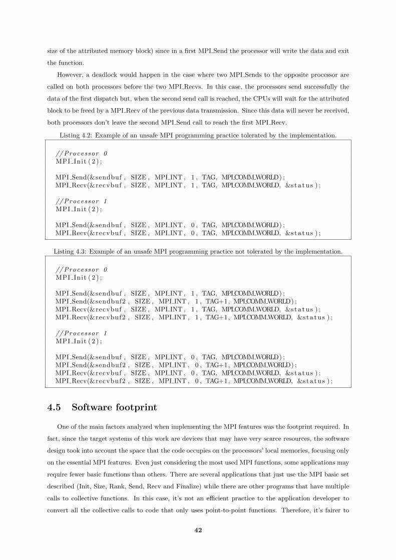
size of the attributed memory block) since in a first MPI Send the processor will write the data and exit
the function.
However, a deadlock would happen in the case where two MPI Sends to the opposite processor are
called on both processors before the two MPI Recvs. In this case, the processors send successfully the
data of the first dispatch but, when the second send call is reached, the CPUs will wait for the attributed
block to be freed by a MPI Recv of the previous data transmission. Since this data will never be received,
both processors don’t leave the second MPI Send call to reach the first MPI Recv.
Listing 4.2: Example of an unsafe MPI programming practice tolerated by the implementation.
// Processor 0MPI Init ( 2 ) ;
MPI Send(&sendbuf , SIZE , MPI INT , 1 , TAG, MPI COMM WORLD) ;MPI Recv(&recvbuf , SIZE , MPI INT , 1 , TAG, MPI COMM WORLD, &s t a t u s ) ;
// Processor 1MPI Init ( 2 ) ;
MPI Send(&sendbuf , SIZE , MPI INT , 0 , TAG, MPI COMM WORLD) ;MPI Recv(&recvbuf , SIZE , MPI INT , 0 , TAG, MPI COMM WORLD, &s t a t u s ) ;
Listing 4.3: Example of an unsafe MPI programming practice not tolerated by the implementation.
// Processor 0MPI Init ( 2 ) ;
MPI Send(&sendbuf , SIZE , MPI INT , 1 , TAG, MPI COMM WORLD) ;MPI Send(&sendbuf2 , SIZE , MPI INT , 1 , TAG+1, MPI COMM WORLD) ;MPI Recv(&recvbuf , SIZE , MPI INT , 1 , TAG, MPI COMM WORLD, &s t a t u s ) ;MPI Recv(&recvbuf2 , SIZE , MPI INT , 1 , TAG+1, MPI COMM WORLD, &s t a t u s ) ;
// Processor 1MPI Init ( 2 ) ;
MPI Send(&sendbuf , SIZE , MPI INT , 0 , TAG, MPI COMM WORLD) ;MPI Send(&sendbuf2 , SIZE , MPI INT , 0 , TAG+1, MPI COMM WORLD) ;MPI Recv(&recvbuf , SIZE , MPI INT , 0 , TAG, MPI COMM WORLD, &s t a t u s ) ;MPI Recv(&recvbuf2 , SIZE , MPI INT , 0 , TAG+1, MPI COMM WORLD, &s t a t u s ) ;
4.5 Software footprint
One of the main factors analyzed when implementing the MPI features was the footprint required. In
fact, since the target systems of this work are devices that may have very scarce resources, the software
design took into account the space that the code occupies on the processors’ local memories, focusing only
on the essential MPI features. Even just considering the most used MPI functions, some applications may
require fewer basic functions than others. There are several applications that just use the MPI basic set
described (Init, Size, Rank, Send, Recv and Finalize) while there are other programs that have multiple
calls to collective functions. In this case, it’s not an efficient practice to the application developer to
convert all the collective calls to code that only uses point-to-point functions. Therefore, it’s fairer to
42

indicate the software footprint based on the function set it implements. Besides the distinction between
a basic set and a set that also contains the collective functions, it’s also important to distinguish the
footprint of the version with the implementation of the function MPI Wtime since, in order to allow
different timer configurations, this function is only available in a new package different from the set with
the other implemented functions.
Table 4.3 shows the footprint of each one of the described function sets. It’s important to note that
the implemented functions call the xil printf function which, despite being much lighter than the standard
printf function, still occupies a significant part of the size of the code stored in the MicroBlaze memories.
As shown in Table 4.3, there is a significant increase of the footprint when the set that also implements
the collective functions is used. The main responsible for this increase is the MPI Reduce function which
accounts for 60 % of this increase. In fact, allowing both the sum and product as reduce operations for
4-bytes and 8-bytes floating-point and non floating-point datatypes required a significant amount of code.
In this table, the MPI Barrier primitive was considered a function belonging to the Basic Set because the
fundamental functions that start and finish the MPI session (MPI Init and MPI Finalize, respectively)
use the barrier to synchronize all the processors.
Table 4.3: Footprints of the implemented MPI function sets in the MicroBlaze soft-processor.Function Set Functions implemented Zynq ARM compatibility Footprint
Basic Set MPI Init, MPI Comm size,MPI Comm rank, MPI Send,MPI Recv, MPI Finalize,MPI Barrier
Yes 10.3 kB
Collective Set Basic set functions,MPI Bcast, MPI Reduce,MPI Gather, MPI Scatter
Yes 25.4 kB
Timer Set Collective set functions,MPI Wtime
No 31.3 kB
4.6 Software compatibility with Heterogeneous system
The heterogeneous multi-processing architecture also uses the same memory to allow the MPI com-
munication between the soft and hard processors. Therefore, the extension of the software to make it
compatible with the 2 systems only required simple changes related with the assignment of the pro-
cessor ranks. While the FPGA-only system may rely exclusively in the Xilinx rank assignment, the
heterogeneous system cannot because the Xilinx assignment for the ARM cores is independent from the
assignment for the MicroBlazes. In fact, if the two ARM cores and two Microblaze processors are used,
the Xilinx drivers assign two processors with the rank 0 and two processors with the rank 1. In order
to maintain the compatibility between both versions, the Xilinx assignment was maintained in the Mi-
43

croBlazes while the implementation assigns new rank values to the ARM cores. The software detects if
the processor trying to initialize the MPI session is a MicroBlaze or an ARM Core. If it’s the first ARM
Core the implementation will assign the last communication rank, if it’s the second ARM Core, the im-
plementation will assign the second-to-last communication rank . The last rank and second-to-last ranks
are determined by reading the MPI group size value, Np, specified as an MPI Init argument. Therefore,
the MPI user shall specify, in the heterogeneous system, the group size as the total number of processors
(MicroBlazes + ARM Cores) and not only the number of MicroBlaze processors.
Table 4.4: Rank assignment example when multiple MicroBlazes and the two ARM-Cores are launched.CPU Architecture Xilinx rank MPI rank
MicroBlaze 0 0MicroBlaze 1 1MicroBlaze 2 2MicroBlaze 3 3
ARM Cortex A-9 0 5ARM Cortex A-9 1 4
Table 4.5: Rank assignment example when multiple MicroBlazes and one ARM-Core are launched.CPU Architecture Xilinx rank MPI rank
MicroBlaze 0 0MicroBlaze 1 1MicroBlaze 2 2MicroBlaze 3 3
ARM Cortex A-9 0 4
Table 4.6: Rank assignment of the MPI implementation when only the two ARM Cores are launchedCPU Architecture Xilinx rank MPI rankARM Cortex A-9 0 1ARM Cortex A-9 1 0
These software changes were enough to provide software compatibility with both architectures. After
the assignment of a rank, the implementation views the ARM Core as a processor equivalent to the
soft-core processors and, therefore, the logical division and the software facilities to manipulate the MPI
memory are maintained. The datatype compatibility is also maintained since the size of the datatypes is
equal in both CPUs.
The exception regarding the heterogeneous system compatibilities is the already referred MPI Wtime
function since it relies on the MicroBlaze drivers. Since the ARM Cores may use different timer configu-
rations and access functions, the specific implementation was not considered. However, if necessary, this
extension would not be a complex task.
4.7 Conclusions
This chapter described the development and implementation of an efficient and lightweight MPI
library, supporting the most used communication functions, for the proposed multi-processing architec-
tures.
44

The architecture uses the MPI memory in order to efficiently implement a balanced data transfer for all
the processor combinations. With the basic communication mode for the point-to-point communication
functions, a sender processor only sends a chunk of data to the receiver processor when it’s confirmed
that the latest chunk of data to the same receiver was already read. A relatively small memory (about
8kB) is appropriate to implement the required MPI message buffering.
The implementation detects the main errors present in the MPI applications and, in some case, can
tolerate some common bad programming practices. The total footprint of all the functions is less than
27 kB (the MPI Barrier function is the most complex function implemented).
The MPI library and the proposed architecture were successfully validated by executing a number of
benchmarks, as described in the next chapter.
45

46
5Experimental results
Contents5.1 Testbed . . . . . . . . . . . . . . . . . . . . . . . . . . . . . . . . . . . . . . . . 48
5.2 FPGA homogeneous system . . . . . . . . . . . . . . . . . . . . . . . . . . . . 49
5.2.1 System setup . . . . . . . . . . . . . . . . . . . . . . . . . . . . . . . . . . . . . 49
5.2.2 Pi-Calculus . . . . . . . . . . . . . . . . . . . . . . . . . . . . . . . . . . . . . . 51
5.2.3 Matrix-vector multiplication . . . . . . . . . . . . . . . . . . . . . . . . . . . . . 52
5.2.4 Backward substitution . . . . . . . . . . . . . . . . . . . . . . . . . . . . . . . . 55
5.3 Zynq heterogeneous system . . . . . . . . . . . . . . . . . . . . . . . . . . . . 56
5.3.1 System setup . . . . . . . . . . . . . . . . . . . . . . . . . . . . . . . . . . . . . 57
5.3.2 Sieve of Eratosthenes . . . . . . . . . . . . . . . . . . . . . . . . . . . . . . . . 58
5.3.3 Modified pi-calculus . . . . . . . . . . . . . . . . . . . . . . . . . . . . . . . . . 59
5.4 Conclusions . . . . . . . . . . . . . . . . . . . . . . . . . . . . . . . . . . . . . . 60
47
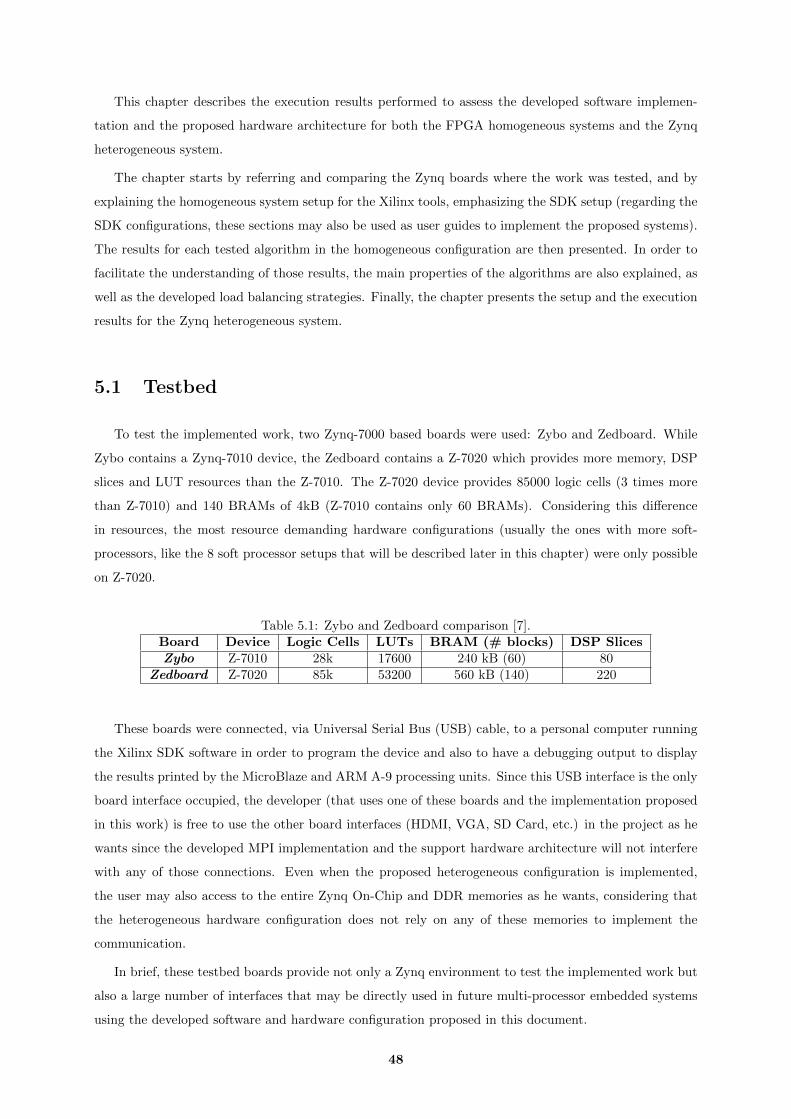
This chapter describes the execution results performed to assess the developed software implemen-
tation and the proposed hardware architecture for both the FPGA homogeneous systems and the Zynq
heterogeneous system.
The chapter starts by referring and comparing the Zynq boards where the work was tested, and by
explaining the homogeneous system setup for the Xilinx tools, emphasizing the SDK setup (regarding the
SDK configurations, these sections may also be used as user guides to implement the proposed systems).
The results for each tested algorithm in the homogeneous configuration are then presented. In order to
facilitate the understanding of those results, the main properties of the algorithms are also explained, as
well as the developed load balancing strategies. Finally, the chapter presents the setup and the execution
results for the Zynq heterogeneous system.
5.1 Testbed
To test the implemented work, two Zynq-7000 based boards were used: Zybo and Zedboard. While
Zybo contains a Zynq-7010 device, the Zedboard contains a Z-7020 which provides more memory, DSP
slices and LUT resources than the Z-7010. The Z-7020 device provides 85000 logic cells (3 times more
than Z-7010) and 140 BRAMs of 4kB (Z-7010 contains only 60 BRAMs). Considering this difference
in resources, the most resource demanding hardware configurations (usually the ones with more soft-
processors, like the 8 soft processor setups that will be described later in this chapter) were only possible
on Z-7020.
Table 5.1: Zybo and Zedboard comparison [7].Board Device Logic Cells LUTs BRAM (# blocks) DSP SlicesZybo Z-7010 28k 17600 240 kB (60) 80
Zedboard Z-7020 85k 53200 560 kB (140) 220
These boards were connected, via Universal Serial Bus (USB) cable, to a personal computer running
the Xilinx SDK software in order to program the device and also to have a debugging output to display
the results printed by the MicroBlaze and ARM A-9 processing units. Since this USB interface is the only
board interface occupied, the developer (that uses one of these boards and the implementation proposed
in this work) is free to use the other board interfaces (HDMI, VGA, SD Card, etc.) in the project as he
wants since the developed MPI implementation and the support hardware architecture will not interfere
with any of those connections. Even when the proposed heterogeneous configuration is implemented,
the user may also access to the entire Zynq On-Chip and DDR memories as he wants, considering that
the heterogeneous hardware configuration does not rely on any of these memories to implement the
communication.
In brief, these testbed boards provide not only a Zynq environment to test the implemented work but
also a large number of interfaces that may be directly used in future multi-processor embedded systems
using the developed software and hardware configuration proposed in this document.
48
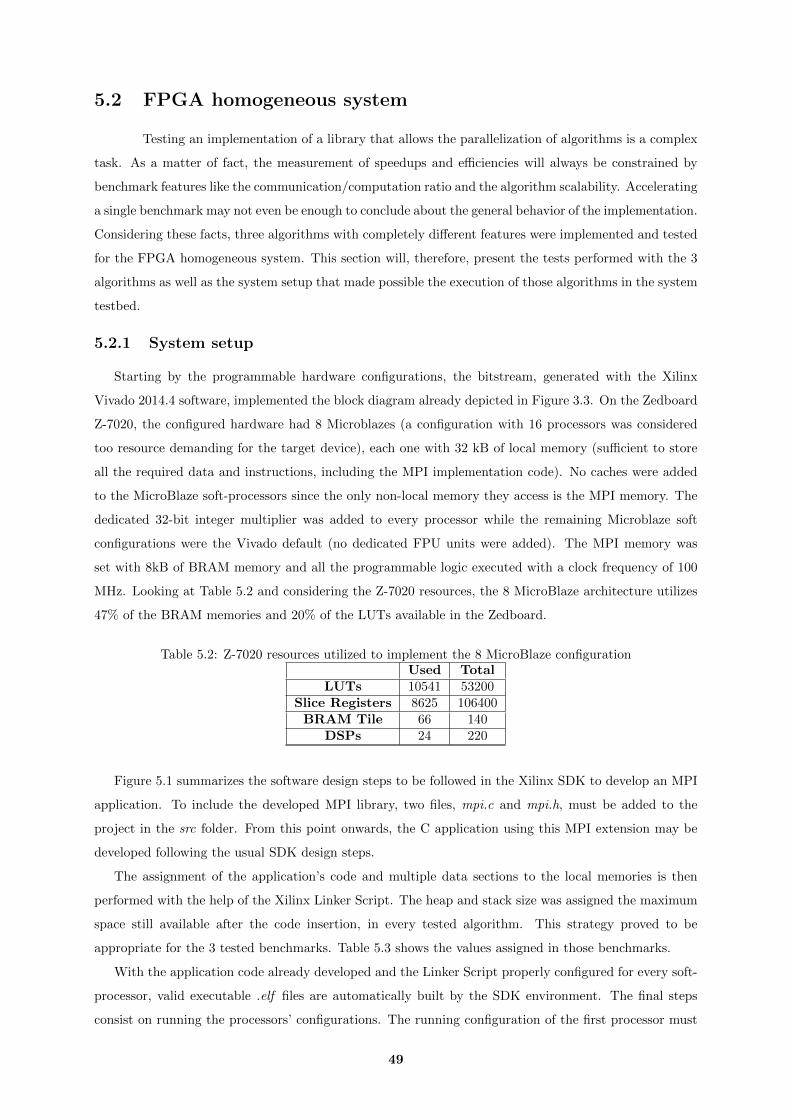
5.2 FPGA homogeneous system
Testing an implementation of a library that allows the parallelization of algorithms is a complex
task. As a matter of fact, the measurement of speedups and efficiencies will always be constrained by
benchmark features like the communication/computation ratio and the algorithm scalability. Accelerating
a single benchmark may not even be enough to conclude about the general behavior of the implementation.
Considering these facts, three algorithms with completely different features were implemented and tested
for the FPGA homogeneous system. This section will, therefore, present the tests performed with the 3
algorithms as well as the system setup that made possible the execution of those algorithms in the system
testbed.
5.2.1 System setup
Starting by the programmable hardware configurations, the bitstream, generated with the Xilinx
Vivado 2014.4 software, implemented the block diagram already depicted in Figure 3.3. On the Zedboard
Z-7020, the configured hardware had 8 Microblazes (a configuration with 16 processors was considered
too resource demanding for the target device), each one with 32 kB of local memory (sufficient to store
all the required data and instructions, including the MPI implementation code). No caches were added
to the MicroBlaze soft-processors since the only non-local memory they access is the MPI memory. The
dedicated 32-bit integer multiplier was added to every processor while the remaining Microblaze soft
configurations were the Vivado default (no dedicated FPU units were added). The MPI memory was
set with 8kB of BRAM memory and all the programmable logic executed with a clock frequency of 100
MHz. Looking at Table 5.2 and considering the Z-7020 resources, the 8 MicroBlaze architecture utilizes
47% of the BRAM memories and 20% of the LUTs available in the Zedboard.
Table 5.2: Z-7020 resources utilized to implement the 8 MicroBlaze configurationUsed Total
LUTs 10541 53200Slice Registers 8625 106400
BRAM Tile 66 140DSPs 24 220
Figure 5.1 summarizes the software design steps to be followed in the Xilinx SDK to develop an MPI
application. To include the developed MPI library, two files, mpi.c and mpi.h, must be added to the
project in the src folder. From this point onwards, the C application using this MPI extension may be
developed following the usual SDK design steps.
The assignment of the application’s code and multiple data sections to the local memories is then
performed with the help of the Xilinx Linker Script. The heap and stack size was assigned the maximum
space still available after the code insertion, in every tested algorithm. This strategy proved to be
appropriate for the 3 tested benchmarks. Table 5.3 shows the values assigned in those benchmarks.
With the application code already developed and the Linker Script properly configured for every soft-
processor, valid executable .elf files are automatically built by the SDK environment. The final steps
consist on running the processors’ configurations. The running configuration of the first processor must
49
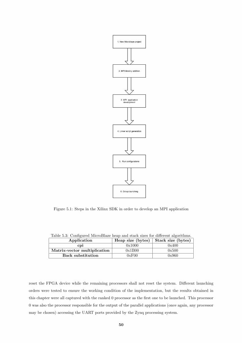
Figure 5.1: Steps in the Xilinx SDK in order to develop an MPI application
Table 5.3: Configured MicroBlaze heap and stack sizes for different algorithms.Application Heap size (bytes) Stack size (bytes)
cpi 0x1000 0x400Matrix-vector multiplication 0x1B00 0x500
Back substitution 0xF00 0x960
reset the FPGA device while the remaining processors shall not reset the system. Different launching
orders were tested to ensure the working condition of the implementation, but the results obtained in
this chapter were all captured with the ranked 0 processor as the first one to be launched. This processor
0 was also the processor responsible for the output of the parallel applications (once again, any processor
may be chosen) accessing the UART ports provided by the Zynq processing system.
50

5.2.2 Pi-Calculus
The first benchmark considered was a port of the cpi application available as an example of the
MPICH2 implementation [9]. This algorithm computes an accurate value (using a double variable) of
the number pi. The parallel portion of the algorithm starts with a broadcast of the total number of
iterations, then each processor performs the determined iterations and, finally, a reduce operation of sum
is performed in order to the master processor obtain the final value. The following pseudo-code illustrates
these steps.
Listing 5.1: Pseudo-code for the cpi algorithm
Broadcast (n ) ;h = 1 .0 / n ;sum = 0 . 0 ;for ( i = myid + 1 ; i <= n ; i += numprocs ){
x = h ∗ ( i − 0 . 5 ) ;sum += 4.0 / ( 1 . 0 + x∗x ) ;
}mypi = h ∗ sum ;Reduce ( mypi , f i n a l p i ) ;
With this algorithm, the transmission of both 4-byte and 8-byte datatypes (MPI INT and MPI DOUBLE,
respectively) was validated. In order to also validate the maximum number of MPI functions, a version
of this benchmark using the MPI Sends and MPI Recvs (instead of the MPI Bcast and MPI Reduce
functions) was also validated (and used for the performance measurement since this method requires
much less memory). All the validated functions are summarized in the following table (the MPI Barrier
is tested since the MPI Init routine calls internally the function).
Table 5.4: MPI functions validated using the cpi benchmark.Session setup
& inquiryfunctions
Point-to-pointfunctions
Collectivefunctions
MPI InitMPI Comm rankMPI Comm size
MPI Finalize
MPI SendMPI Recv
MPI BcastMPI ReduceMPI Barrier
The MPI version of this iterative algorithm has a very low communication/computation ratio since it
only needs an initial broadcast of the number of iterations and a final reduce of the pi values computed by
each processor. The following tables show the speedups and efficiencies obtained for a different number
of cpi iterations and executing processors:
51
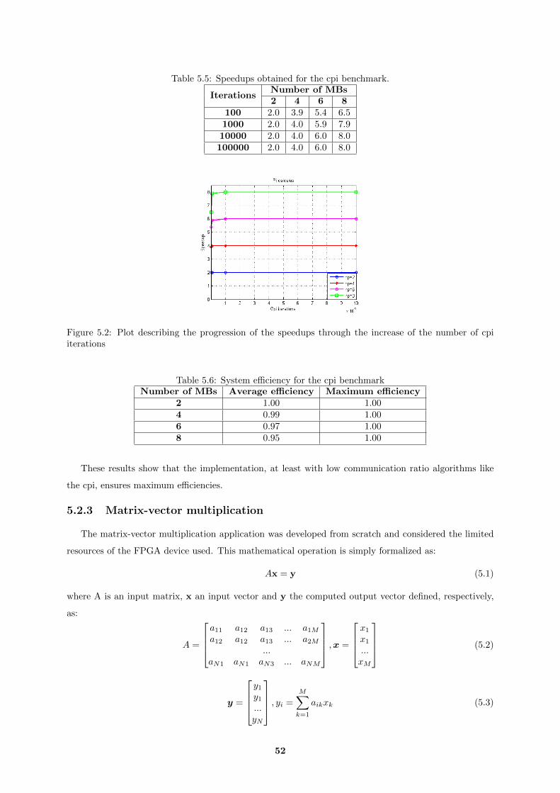
Table 5.5: Speedups obtained for the cpi benchmark.
IterationsNumber of MBs2 4 6 8
100 2.0 3.9 5.4 6.51000 2.0 4.0 5.9 7.910000 2.0 4.0 6.0 8.0100000 2.0 4.0 6.0 8.0
Figure 5.2: Plot describing the progression of the speedups through the increase of the number of cpiiterations
Table 5.6: System efficiency for the cpi benchmarkNumber of MBs Average efficiency Maximum efficiency
2 1.00 1.004 0.99 1.006 0.97 1.008 0.95 1.00
These results show that the implementation, at least with low communication ratio algorithms like
the cpi, ensures maximum efficiencies.
5.2.3 Matrix-vector multiplication
The matrix-vector multiplication application was developed from scratch and considered the limited
resources of the FPGA device used. This mathematical operation is simply formalized as:
Ax = y (5.1)
where A is an input matrix, x an input vector and y the computed output vector defined, respectively,
as:
A =
a11 a12 a13 ... a1Ma12 a12 a13 ... a2M
...aN1 aN1 aN3 ... aNM
,x =
x1
x1
...xM
(5.2)
y =
y1y1...yN
, yi =
M∑k=1
aikxk (5.3)
52

Due to local memory size limitations, the Microblazes only store a single A line as well as the x and y
vectors. Consequently, considering a square A matrix, only 3 arrays of size N are locally stored, instead
of two arrays of size N and a matrix of size N2.
After the MPI initialization, the algorithm starts by a broadcast of the vector x. Then, the multi-
plication loop is performed with the processors receiving, at each iteration, a new A row, discarding the
previous one and computing the resulting y value. This distribution of the rows of matrix A is interleaved
between all the processors. After all the processors compute their corresponding y elements, the entire y
data is gathered to the master processor.
p0 a00 a01 ... a09p1 a10 a11 ... a19p2 a20 a21 ... a29p3 a30 a31 ... a39p0 a40 a41 ... a49p1 a50 a51 ... a59p2 a60 a61 ... a69p3 a70 a71 ... a79p0 a80 a81 ... a89p1 a90 a91 ... a99
Figure 5.3: Example of the distribution of a square matrix A [10][10] in the matrix-vector multiplicationalgorithm running with 4 CPUs.
Besides the fundamental MPI session functions, this algorithm also validated the implementation of
the point-to-point communication functions, the MPI Barrier and the MPI Bcast (in the transmission of
the x vector).
Table 5.7: MPI functions validated using the matrix-vector multiplication benchmark.Session setup
& inquiryfunctions
Point-to-pointfunctions
Collectivefunctions
MPI InitMPI Comm rankMPI Comm size
MPI Finalize
MPI SendMPI Recv
MPI BcastMPI Barrier
This algorithm is considerably more demanding than the cpi application in terms of communication per
computation ratio. In fact, the matrix-vector communication pattern requires much more transmissions:
the initial broadcast transmits N elements to Np processors, the matrix distribution requires N2× Np−1Np
element transmissions and the final gathering also needs N × Np−1Np
transmissions.
The tests were performed with float square matrices with sizes ranging from [50][50] to [300][300].
The results are shown in the following tables.
53

Table 5.8: Speedups obtained for the developed matrix-vector multiplication benchmarkMatrixsizes
Number of MBs2 4 6 8
[50][50] 1.8 3.1 4.0 4.0[100][100] 1.9 3.3 3.9 4.4[150][150] 1.9 3.3 3.9 4.4[200][200] 1.9 3.1 4.0 4.5[250][250] 1.9 3.1 4.0 4.4[300][300] 1.9 3.2 4.0 4.5
Figure 5.4: Plot describing the progression of the matrix-vector multiplication speedups through theincrease of the matrix sizes
Table 5.9: System efficiency for the developed matrix-vector multiplication benchmarkNumber of MBs Average efficiency Maximum efficiency
2 0.94 0.944 0.80 0.836 0.66 0.678 0.54 0.56
Analysing the results obtained, two effects are verified: the transmission of the workload in several
chunks and the excessive communication overhead (since the efficiencies decrease with the number of
processors). As already explained in this document, the effect of the data transmission in chunks implies
a slight decrease of the implementation performance. This effect is primarily observed in the transition
from the matrix sizes [150][150] to [200][200] with 4 processors. Since the MPI memory was configured to
have a size of 8192 bytes, the maximum number of float elements to send in a chunk for each combination
is:
# floats in a chunk for 4 MBs =blocksize− 4
4=b 81924×3 c − 2− 4
4= 169 (5.4)
Hence, the arrays with size 150 are still transmitted in one chunk but arrays with size 200 need two
chunks. This additional overhead resulted in the decrease of two tenths of the speedup in this first case.
The other example of this effect is present in the transition from the matrix size [50][50] to [100][100]
when 6 processors execute the application. This time, the speedup decreases only one tenth. Doubling
the MPI memory size would remove this small overhead in the two cases.
54
5.2.4 Backward substitution
Considering a system of equations defined in the matrix form Ax = b, the backward substitution is
the process of solving that system of equations when the matrix A is an upper-triangular matrix. The
algorithm to solve a problem of this kind is generically described by the following code:
Listing 5.2: Backward substitution algorithm example
for ( i = N−1; i >= 0 ; i−−){b [ i ] = b [ i ] / A[ i ] [ i ] ;for ( j = 0 ; j < i ; j++) b [ j ] = b [ j ] − b [ i ] ∗ A[ j ] [ i ] ; }
Like the matrix-vector multiplication algorithm, the parallelization of this algorithm requires the
transmission of an array of matrix elements (in this case, a column instead of a line) for each processor in
each iteration due to the already referred local memory limitations. Despite the distribution per columns
in each iteration, the assignment described in Figure 5.3 is still valid, considering now the matrix A as
an upper-triangular matrix.
The parallelization of the back substitution is, however, less efficient than the MPI matrix-vector
multiplication because only the internal loop of the algorithm is parallelizable. Therefore, every processor
must run all the iterations of the external loop. In each iteration of this loop, the b[i] value (pivot)
is computed by a different processor and broadcasted to the other processors. The broadcast of this
value is a critical point in the algorithm and, therefore, an ideal evaluation of the optimized MPI Bcast
implementation is provided. To complete the parallel algorithm, there is the usual data gathering of the
vector b to the master processor after the computation.
The tested and validated functions in this benchmark are presented in Table 5.10. The speedups
obtained are shown in Table 5.11.
Table 5.10: MPI functions validated using the backward benchmark.Session setup
& inquiryfunctions
Point-to-pointfunctions
Collectivefunctions
MPI InitMPI Comm rankMPI Comm size
MPI Finalize
MPI SendMPI Recv
MPI BcastMPI Barrier
Table 5.11: Speedups obtained for the developed backward substitution benchmarkMatrixsizes
Number of MBs2 4 6 8
[100][100] 1.5 2.3 2.5 2.3[200][200] 1.6 2.5 2.8 2.6[300][300] 1.6 2.6 2.9 2.8[400][400] 1.6 2.7 3.0 2.8[500][500] 1.6 2.7 3.1 2.9[600][600] 1.6 2.7 3.1 2.9
55

Figure 5.5: Plot describing the progression of the back substitution speedups through the increase of thematrix sizes
Table 5.12: System efficiency obtained for the developed backward substitution benchmarkNumber of MBs Average efficiency Maximum efficiency
2 0.80 0.824 0.64 0.686 0.48 0.528 0.34 0.36
These results show that the maximum speedup obtained was achieved with 6 processors and not
with 8 processors. In fact, the difficult algorithm parallelization and the large communication overhead
limits the system scalability in this benchmark. As a consequence, increasing the number of MicroBlazes
above 8 in the hardware setup or using FPGA devices with much more resources will not accelerate more
this benchmark. Nonetheless, the developed implementation proved to be fully functional also with this
benchmark.
Finally, it’s important to note that an MPI version using the point-to-point functions to perform
the pivot broadcast was also tested and the results were considerably worse. This algorithm proves
that, while the optimized MPI Bcast may have a bigger footprint, this function also provides better
performance when the broadcast is a crucial operation for the system performance.
5.3 Zynq heterogeneous system
Selecting algorithms that exploit the parallelism of the described Zynq heterogeneous system is a more
difficult task than finding algorithms for a system only consisted by MicroBlaze soft-processors. In fact,
since the ARM cores perform floating point operations more than 10 times faster than the MicroBlazes
with a dedicated floating-point unit, the addition of a MicroBlaze will only mean that, in the best case
scenario, the execution time will only be reduced in 10% (instead of being halved). Even with this
consideration, the algorithm computational time to perform NNp
iterations in the ARM cores may be less
than transmitting NNp
elements through a Programmable Logic-Processing System link. Therefore, two
fundamental requirements were defined to select an appropriate benchmark:
• Low communication/computation ratio
56

• Used datatypes compatible with MicroBlaze dedicated processing units.
After the description of the used setup to test the system, this section presents, in first place, algo-
rithms parallelizable with the two ARM cores. This provided also a demonstration that the developed
MPI library may be even used in systems not containing FPGA soft-cores. Finally, a modified cpi
algorithm executing in the heterogeneous system is evaluated in this architecture..
5.3.1 System setup
The multi-processing architecture illustrated by Figure 3.4, the defined communication protocol and
the manual peripheral memory mapping were implemented. In this heterogeneous system, the most
important issue to be tested is the communication between ARM Cores and the Programmable Logic.
Thus, only two MicroBlazes were added to the design. With this setup, the Zybo board was used to
evaluate the system. Despite requiring a considerable amount of resources, a dedicated floating-point
unit was added to each MicroBlaze soft-processor in order to attenuate the performance gap between
the ARM cores and the MicroBlazes. As in the FPGA homogeneous system setup, each MicroBlaze
soft-processor had a dedicated integer multiplier unit and 32 kB of local memory. The MPI memory
was also configured to have 8 kB and the AXI-Timer was compatible with the 64-bit mode. Table 5.13
summarizes the resource utilization report generated for this FPGA implementation.
Table 5.13: Z-7010 resources utilized to implement the heterogeneous configuration with 2 MicroBlazesUsed Total
LUTs 5742 17600Slice Registers 5241 35200
BRAM Tile 18 60DSPs 10 80
The SDK setup steps were the same as those followed in the homogeneous system section. However,
some considerations were specifically taken into account for this heterogeneous architecture.
First of all, due to a Xilinx SDK 2014.4 bug with this configuration, some warnings per processor are
generated when each application is built. These warnings won’t affect the execution of the application but,
nonetheless, these messages may be removed with a few changes in the driver (board support package)
files. The files to be changed are the xbram g.c and the xparameters.h (the path of the files is indicated
by the SDK when the warnings are generated). For the first case, it was developed, in this work, a
xbram g.c file that solves the issue and, therefore, the developer only needs to replace this file in his
projects. Regarding the xparameters.h file, the user shall remove only 2 code lines. The problem in this
file consists in the automatic redefinition of two C defines and, therefore, the user shall remove those two
wrong defines. These wrong defines assign the value 0x00000000 to both the base and high address of
the BRAM controller. Usually, the defines to be removed appear with the following code:
Listing 5.3: Lines to be removed in the xparameters.h file of the SDK projects.
#d e f i n e XPAR BRAM 0 BASEADDR 0x00000000#d e f i n e XPAR BRAM 0 HIGHADDR 0x00000000
57
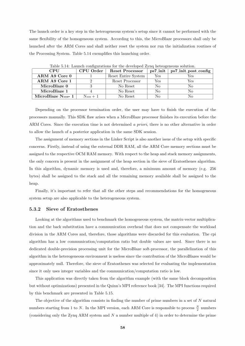
The launch order is a key step in the heterogeneous system’s setup since it cannot be performed with the
same flexibility of the homogeneous system. According to this, the MicroBlaze processors shall only be
launched after the ARM Cores and shall neither reset the system nor run the initialization routines of
the Processing System. Table 5.14 exemplifies this launching order.
Table 5.14: Launch configurations for the developed Zynq heteogeneous solution.CPU CPU Order Reset Processor ps7 init ps7 init post config
ARM A9 Core 0 1 Reset Entire System Yes YesARM A9 Core 1 2 Reset Processor Yes Yes
MicroBlaze 0 3 No Reset No NoMicroBlaze 1 4 No Reset No No
MicroBlaze NMB- 1 NMB + 1 No Reset No No
Depending on the processor termination order, the user may have to finish the execution of the
processors manually. This SDK flaw arises when a MicroBlaze processor finishes its execution before the
ARM Cores. Since the execution time is not determined a priori, there is no other alternative in order
to allow the launch of a posterior application in the same SDK session.
The assignment of memory sections in the Linker Script is also another issue of the setup with specific
concerns. Firstly, instead of using the external DDR RAM, all the ARM Core memory sections must be
assigned to the respective OCM RAM memory. With respect to the heap and stack memory assignments,
the only concern is present in the assignment of the heap section in the sieve of Eratosthenes algorithm.
In this algorithm, dynamic memory is used and, therefore, a minimum amount of memory (e.g. 256
bytes) shall be assigned to the stack and all the remaining memory available shall be assigned to the
heap.
Finally, it’s important to refer that all the other steps and recommendations for the homogeneous
system setup are also applicable to the heterogeneous system.
5.3.2 Sieve of Eratosthenes
Looking at the algorithms used to benchmark the homogeneous system, the matrix-vector multiplica-
tion and the back substitution have a communication overhead that does not compensate the workload
division in the ARM Cores and, therefore, those algorithms were discarded for this evaluation. The cpi
algorithm has a low communication/computation ratio but double values are used. Since there is no
dedicated double-precision processing unit for the MicroBlaze soft-processor, the parallelization of this
algorithm in the heterogeneous environment is useless since the contribution of the MicroBlazes would be
approximately null. Therefore, the sieve of Eratosthenes was selected for evaluating the implementation
since it only uses integer variables and the communication/computation ratio is low.
This application was directly taken from the algorithm example (with the same block decomposition
but without optimizations) presented in the Quinn’s MPI reference book [34]. The MPI functions required
by this benchmark are presented in Table 5.15.
The objective of the algorithm consists in finding the number of prime numbers in a set of N natural
numbers starting from 1 to N . In the MPI version, each ARM Core is responsible to process N2 numbers
(considering only the Zynq ARM system and N a number multiple of 4) in order to determine the prime
58

Table 5.15: MPI functions validated using the sieve of Eratosthenes benchmark.Session setup
& inquiryfunctions
Point-to-pointfunctions
Collectivefunctions
MPI InitMPI Comm rankMPI Comm size
MPI Finalize
-MPI Bcast
MPI ReduceMPI Barrier
numbers inside the set. To accomplish this computation, each processor must receive√N
log(√N)
[34] root
prime numbers broadcasted by the processor with rank 0. A final MPI Reduce of sum is performed to
determine the final value of prime numbers. The MPI communication is considerably light and consists
of√N
log(√N)
broadcasts of one integer element and 1 reduce operation of also one integer.
Table 5.16: Speedups obtained for the sieve of Eratosthenes algorithm with the 2 ARM MP Cores.N Speedup Efficiency
1000 1.41 0.705000 1.79 0.8910000 1.87 0.9315000 1.90 0.9520000 1.92 0.96
The ARM results confirm the low communication/computation ratio, especially when the N value
is increased (looking at the number of broadcasts and at the algorithm computational profile, it’s easy
to verify that the, comparatively, the computation increases more than the MPI transmissions with the
increase of N).
Considering the defined hardware communication architectures, it’s harder to exploit the paralleliza-
tion of algorithms in the ARM Cores than in the homogeneous system consisted solely by MicroBlaze
processors. Thus, it’s expected that this algorithm would also achieve high efficiencies in the FPGA ho-
mogeneous system. However, the heterogeneous system did not improve the performance of the algorithm
as expected when compared with the 2 ARM Cores system. This fact is explained with the increased
Broadcast transmissions and the ARM-MicroBlaze synchronization spots during the execution. In fact,
this overhead is large enough to overlap the reduction of 10% of the computational execution time of
each MicroBlaze. Considering these facts, this MPI version of the sieve of Eratosthenes is an example of
an algorithm only efficiently parallelizable for the ARM Cores and for the FPGA homogeneous systems.
Even with no performance improvement, executing this benchmark in the heterogeneous architecture
was fundamental because the heterogeneous architecture and the software implementation were validated
for the MPI functions required by this benchmark.
5.3.3 Modified pi-calculus
The modified cpi algorithm was developed specifically in order to provide a test application that is
able to demonstrate an efficient exploitation of the parallelism of the heterogeneous system. Since the
original cpi algorithm requires double variables but the MicroBlaze processors do not have a double-
59
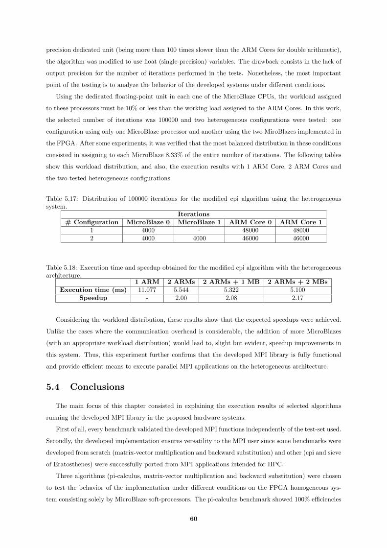
precision dedicated unit (being more than 100 times slower than the ARM Cores for double arithmetic),
the algorithm was modified to use float (single-precision) variables. The drawback consists in the lack of
output precision for the number of iterations performed in the tests. Nonetheless, the most important
point of the testing is to analyze the behavior of the developed systems under different conditions.
Using the dedicated floating-point unit in each one of the MicroBlaze CPUs, the workload assigned
to these processors must be 10% or less than the working load assigned to the ARM Cores. In this work,
the selected number of iterations was 100000 and two heterogeneous configurations were tested: one
configuration using only one MicroBlaze processor and another using the two MiroBlazes implemented in
the FPGA. After some experiments, it was verified that the most balanced distribution in these conditions
consisted in assigning to each MicroBlaze 8.33% of the entire number of iterations. The following tables
show this workload distribution, and also, the execution results with 1 ARM Core, 2 ARM Cores and
the two tested heterogeneous configurations.
Table 5.17: Distribution of 100000 iterations for the modified cpi algorithm using the heterogeneoussystem.
Iterations# Configuration MicroBlaze 0 MicroBlaze 1 ARM Core 0 ARM Core 1
1 4000 - 48000 480002 4000 4000 46000 46000
Table 5.18: Execution time and speedup obtained for the modified cpi algorithm with the heterogeneousarchitecture.
1 ARM 2 ARMs 2 ARMs + 1 MB 2 ARMs + 2 MBsExecution time (ms) 11.077 5.544 5.322 5.100
Speedup - 2.00 2.08 2.17
Considering the workload distribution, these results show that the expected speedups were achieved.
Unlike the cases where the communication overhead is considerable, the addition of more MicroBlazes
(with an appropriate workload distribution) would lead to, slight but evident, speedup improvements in
this system. Thus, this experiment further confirms that the developed MPI library is fully functional
and provide efficient means to execute parallel MPI applications on the heterogeneous architecture.
5.4 Conclusions
The main focus of this chapter consisted in explaining the execution results of selected algorithms
running the developed MPI library in the proposed hardware systems.
First of all, every benchmark validated the developed MPI functions independently of the test-set used.
Secondly, the developed implementation ensures versatility to the MPI user since some benchmarks were
developed from scratch (matrix-vector multiplication and backward substitution) and other (cpi and sieve
of Eratosthenes) were successfully ported from MPI applications intended for HPC.
Three algorithms (pi-calculus, matrix-vector multiplication and backward substitution) were chosen
to test the behavior of the implementation under different conditions on the FPGA homogeneous sys-
tem consisting solely by MicroBlaze soft-processors. The pi-calculus benchmark showed 100% efficiencies
60
independently of the number of tested processors. The matrix-vector multiplication and the backward
substitution, being algorithms that require much more inter-processor communication, have scalability
limitations. Even so, the algorithms were accelerated up to 4.5 times in the matrix-vector multiplica-
tion and up to 3.1 times in the backward substitution. The slight overhead of dividing the data of a
transmission in chunks is also noticeable in the matrix-vector multiplication benchmark.
For the heterogeneous system, test applications were selected with a low communication per com-
putation ratio and that used datatypes for which the MicroBlaze processors have dedicated processing
units (integer or float). Since the matrix-vector and back substitution algorithms require a considerable
amount of data to be transmitted, and the pi-calculus uses double data, new applications were tested
for the heterogeneous architecture. Firstly, a sieve of Eratosthenes algorithm was used but the commu-
nication overhead was still demanding for the heterogeneous system (nonetheless, the system executed
flawlessly this parallel application). A pi-calculus algorithm using float variables was developed to further
demonstrate that the heterogeneous system improved the performance of this benchmark when compared
with the execution on the two ARM Cores.
61

62

6Conclusions
Contents6.1 Future work . . . . . . . . . . . . . . . . . . . . . . . . . . . . . . . . . . . . . . 64
63

The main objectives of the work presented in this document consisted in studying and developing
solutions to implement the MPI interface in distributed memory soft-processors. While requirements
like system reliability and performance were, first and foremost, mentioned, the state of the art analysis
revealed that the scalability and the resource utilization were especially relevant topics to be considered
in this work.
The defined hardware structure to support the MPI communication took into account these require-
ments: the communication structure, based on a memory dedicated for the MPI purpose, requires a
small and scalable amount of resources (considering, especially, the BRAM memories) and the system
does not impose per se a maximum limit for the number processors (this limit depends only on the device
resources). Regarding the BRAM memories used (the crucial point of the resource utilization) the main
concern has to do with the size of the local memories of each processor and not with the memory used
to support the MPI communication. In order to minimize the local memory size, the implemented MPI
library was designed to be as simple as possible (but being compatible with every relevant datatype).
The program size of the MPI basic set is approximately 10 kB and the remaining implemented collective
functions (not counting with the MPI Reduce primitive) do not increase significantly that footprint value.
In this work, three MPI applications with distinct features were selected to evaluate the behavior of the
same system for different communication requirements. All the MPI functions required by these bench-
marks executed flawlessly. The two collective MPI functions that aren’t called by the tested benchmarks
(MPI Gather and MPI Scatter) were also exhaustively tested. The fact that a benchmark developed
for mainframe systems (cpi) was easily ported to the target devices indicates that a wide range of MPI
applications are also easily ported to proposed architectures.
Drawing conclusions about the performance of the MPI implementation is a challenging task since
the speedups obtained always depend of factors oblivious to the MPI implementation such as the compu-
tational properties of the MPI algorithms themselves. The tests performed showed that algorithms with
low communication/computation ratio (like the cpi) achieved perfect efficiencies.
A fully-working implementation for the Zynq heterogeneous system was also developed. In this case,
the developed MPI software was extended to make it compatible with the 2 systems. The extension was
very simple since the heterogeneous architecture is based on ARM Cores being also connected to the
same memory for the MPI communication. The solution was validated with the successful execution of
the ported cpi and sieve of Erathostenes benchmarks.
In conclusion, this work has successfully implemented a MPI software library and a set of hardware
support mechanisms to support the implementation of MPI applications on FPGA-based multi-processor
embedded systems. Using these MPI functions and the proposed hardware architectures, a distributed-
system developer can develop and/or port his MPI applications to FPGA soft-processors and Zynq
heterogeneous systems without needing to focus anymore on inter-processor communication details.
6.1 Future work
Future work shall provide solutions in order to improve the MPI transmission performance, such
as setting-up/adapting the soft-processors to perform burst transfers or developing hardware cores to
64

directly support several MPI functions.
The extension of the compatible MPI functions is also a natural future work, though a functional set
is already fully working. The availability of this extension would facilitate even more the task of porting
common workstations applications. The compatibility of functions like MPI Allgather, MPI Alltoall,
MPI ISend and MPI IRecv would be the obvious next steps. Nonetheless, the footprint of this new
portion of code should be minimized.
Regarding the heterogeneous system testing, the reserch and development of algorithms that take
advantage of the implementation may be complemented. The development in FPGA of a dedicated
double-precision processing unit for a MicroBlaze processor would also validate the execution of the
original cpi algorithm in this hardware configuration.
Finally, porting this implementation to embedded/soft-core processors different from the Microblaze
processors and the ARM Cortex A9 Cores would not only add more criteria to analyze the portability of
this work but also add more possibilities to run efficiently algorithms on heterogeneous configurations.
65

66
References
[1] L. Pantaleone and E. Todorovich, “Accelerating embedded software processing in an FPGA with
PowerPC and Microblaze”, INTIA Institute, Universidad Nacional del Centro de la Provincia de
Buenos Aires, 2011.
[2] W. Jose, M.Vestias and H. Neto, “Multiprocessor System in an FPGA”, in VIII Jornadas sobre
Sistemas Reconfiguraveis, 2011, pp.97-104
[3] MPI Forum,“MPI Documents”, http://www.mpi-forum.org/docs/docs.html [Accessed in Septem-
ber, 2015]
[4] S. Lakshminarayana, S. Gosh and N.Balakrishnan, “Implementation of MPI over HTTP” in High-
Performance Computing and Networking: 7th International Conference, 1999, pp.1299-1302
[5] E. Marques, F. Martins, V. Vasconcelos, N. Ng and N. Martins, “Towards deductive verification of
MPI programs against session types” in Programming Language Approaches to Concurrency- and
Communication-cEntric Software, 2013, pp.103-113
[6] V. Sklyarov; I. Skliarova; J. Silva and Alexander Sudnitson, “Analysis and Comparison of Attain-
able Hardware Acceleration in All Programmable Systems-on-Chip” in Proceedings of the Euromicro
Conference on Digital System Design - Euromicro DSD, 2015, pp.345-352
[7] Xilinx, “Zynq-7000 All Programmable SoC”, http://www.xilinx.com/products/silicon-
devices/soc/zynq-7000.html [Accessed in September, 2015]
[8] Innovative Computing Laboratory, “FT-MPI”,http://icl.cs.utk.edu/ftmpi/ [Accessed in March,
2015]
[9] MPICH Team, “MPICH”, https://www.mpich.org/ [Accessed in March, 2015]
[10] Open MPI Team, “Open MPI: Open Source High Performance Computing”, https://www.open-
mpi.org/ [Accessed in September, 2015]
[11] Intel, “Intel MPI Library”, https://software.intel.com/en-us/intel-mpi-library [Accessed
in September, 2015]
[12] IBM, “Platform MPI”, http://www-03.ibm.com/systems/platformcomputing/products/mpi/
[Accessed in September, 2015]
67
[13] The Ohio State University, “MVAPICH: MPI over InfiniBand, 10GigE/iWARP and RoCE”, http:
//mvapich.cse.ohio-state.edu/news[Accessed in September, 2015]
[14] T. McMahon and A. Skjellum, “eMPI/eMPICH: Embedding MPI” in MPIDC ’96: Proceedings of
the Second MPI Developers Conference, 1996, pp.180
[15] RunTime Computing Solutions, “MPI/Pro”, http://www.runtimecomputing.com/products/
mpipro/[Accessed in October 2015]
[16] T. McMahon and A. Skjellum, “eMPI/eMPICH: Embedding MPI” in MPI Developers Conference,
1996, pp.180–184.
[17] J. Poole, “Implementation of a Hardware-Optimized MPI Library for the SCMP Multiprocessor”,
MSc Thesis, 2004
[18] J. Williams, I. Syed, J. Wu and N. Bergmann “A Reconfigurable Clsuter-on-Chip Architecture with
MPI Communication Layer” in Proceedings of 14th Annual IEEE Symposium on Field-Programmable
Custom Computing Machines, 2006, pp.350-352
[19] M. Saldana and P. Chow, “TMD-MPI: An MPI Implementation for Multiple Processors Across
Multiple FPGAs” in Proceedings of the 16th International Conference on Field-Programmable Logic
and Applications, 2006, pp.1-6
[20] I. Syed, J. A. Williams, J. Wu and N. W. Bergmann “A hybrid reconfigurable cluster-on-chip ar-
chitecture with Message Passing Interface for image processing applications” in Field Programmable
Logic and Applications, 2007, pp.609-612
[21] M. Saldana, A. Patel, C. Madill, D. Nunes, D. Wang, H. Styles, A. Putnam, R. Wittig and P.
Cho, “MPI as an Abstraction for Software-Hardware Interaction for HPRCs” in Second International
Workshop on High-Performance Reconfigurable Computing Technology and Applications, 2008, pp.1-
10
[22] D. Ly, M. Saldana and P.Chow, “The Challenges of Using An Embedded MPI for Hardware-based
Processing Nodes” in International Conference on Field-Programmable Technology, 2009, pp.120-127
[23] Y. Peng, M. Saldana and P. Chow, “Hardware Support for Broadcast and Reduce in MPSoC” in
International Conference on Field Programmable Logic and Applications, 2011, pp.144-150
[24] S. Gao, A. Schmidt and R. Sass, “Hardware implementation of MPI Barrier on an FPGA cluster”
in International Conference on Field Programmable Logic and Applications, 2009, pp.12-17
[25] R. Brightwell, K. Hemmert, R. Murphy, A. Rodrigues and K. Underwood “A Hardware Acceleration
Unit for MPI Queue Processing” in Proceedings of 19th IEEE International Parallel and Distributed
Processing Symposium, 2005 pp.96-109
[26] Xilinx, “MicroBlaze Reference Guide”, http://www.xilinx.com/support/documentation/sw_
manuals/mb_ref_guide.pdf [Accessed in September, 2015]
68
[27] Xilinx, “PicoBlaze 8-bit Microcontroller”, http://www.xilinx.com/products/intellectual-
property/picoblaze.html [Accessed in September, 2015]
[28] Lattice, “LatticeMico32 Open, Free 32-Bit Soft Processor”, http://www.latticesemi.com/en/
Products/DesignSoftwareAndIP/IntellectualProperty/IPCore/IPCores02/LatticeMico32.
aspx [Accessed in September, 2015]
[29] Aeroflex Gaisler AB, “LEON3 Processor”, http://www.gaisler.com/index.php/products/
processors/leon3 [Accessed in September, 2015]
[30] T. Kranenburg and R.van Leuken, “MB-LITE: A robust, light-weight soft-core implementation of
the MicroBlaze architecture” in Design, Automation & Test in Europe Conference & Exhibition, 2010,
pp.997-1000
[31] OpenCores, “OR1200 OpenRISC Processor”, http://opencores.org/or1k/OR1200_OpenRISC_
Processor [Accessed in September, 2015]
[32] OpenCores, “OpenFIRE”, http://opencores.org/project,openfire2 [Accessed in September,
2015]
[33] N. Shroff, “Memory Hierarchy for Microblaze and PowerPC based Systems”, MSc Thesis, 2004
[34] M.Quin, “Parallel Programming in C with MPI and OpenMP - 1st Edition”, McGraw-Hill, 2003
69

70

7Appendix A
71
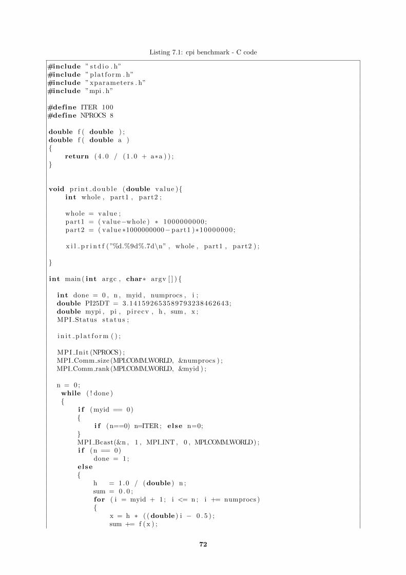
Listing 7.1: cpi benchmark - C code
#include ” s t d i o . h”#include ” plat form . h”#include ” xparameters . h”#include ”mpi . h”
#define ITER 100#define NPROCS 8
double f ( double ) ;double f ( double a ){
return ( 4 . 0 / ( 1 . 0 + a∗a ) ) ;}
void pr in t doub l e (double value ){int whole , part1 , part2 ;
whole = value ;part1 = ( value−whole ) ∗ 1000000000;part2 = ( value ∗1000000000− part1 )∗10000000 ;
x i l p r i n t f ( ”%d.%9d%.7d\n” , whole , part1 , part2 ) ;
}
int main ( int argc , char∗ argv [ ] ) {
int done = 0 , n , myid , numprocs , i ;double PI25DT = 3.141592653589793238462643;double mypi , pi , p i recv , h , sum , x ;MPI Status s t a t u s ;
i n i t p l a t f o r m ( ) ;
MPI Init (NPROCS) ;MPI Comm size (MPI COMM WORLD, &numprocs ) ;MPI Comm rank(MPI COMM WORLD, &myid ) ;
n = 0 ;while ( ! done ){
i f ( myid == 0){
i f (n==0) n=ITER ; else n=0;}MPI Bcast(&n , 1 , MPI INT , 0 , MPI COMM WORLD) ;i f (n == 0)
done = 1 ;else{
h = 1 .0 / (double ) n ;sum = 0 . 0 ;for ( i = myid + 1 ; i <= n ; i += numprocs ){
x = h ∗ ( ( double ) i − 0 . 5 ) ;sum += f ( x ) ;
72

}mypi = h ∗ sum ;
i f ( myid == 0){
pi=mypi ;for ( i =1; i<numprocs ; i ++){
MPI Recv(&pirecv , 1 ,MPI DOUBLE, i , 1 ,MPI COMM WORLD,&s t a t u s ) ;
p i+=p i r e cv ;}x i l p r i n t f ( ” e r r o r :\n” ) ;p r i n t doub l e (PI25DT−pi ) ;
}else {
MPI Send(&mypi , 1 ,MPI DOUBLE, 0 , 1 ,MPI COMM WORLD) ;
}}
}MPI Final ize ( ) ;
c l eanup p la t fo rm ( ) ;return 0 ;
}
73
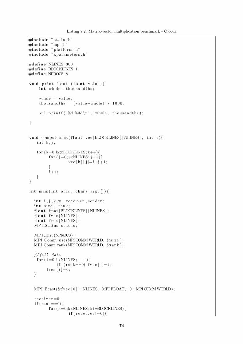
Listing 7.2: Matrix-vector multiplication benchmark - C code
#include ” s t d i o . h”#include ”mpi . h”#include ” plat form . h”#include ” xparameters . h”
#define NLINES 300#define BLOCKLINES 1#define NPROCS 8
void p r i n t f l o a t ( f loat value ){int whole , thousandths ;
whole = value ;thousandths = ( value−whole ) ∗ 1000 ;
x i l p r i n t f ( ”%d.%3d\n” , whole , thousandths ) ;
}
void computefmat ( f loat vec [BLOCKLINES ] [ NLINES ] , int i ){int k , j ;
for ( k=0;k<BLOCKLINES; k++){for ( j =0; j<NLINES ; j++){
vec [ k ] [ j ]= i+j +1;}i ++;
}}
int main ( int argc , char∗ argv [ ] ) {
int i , j , k ,w, r e c e i v e r , sender ;int s i z e , rank ;f loat fmat [BLOCKLINES ] [ NLINES ] ;f loat f v e c [ NLINES ] ;f loat f r e s [ NLINES ] ;MPI Status s t a t u s ;
MPI Init (NPROCS) ;MPI Comm size (MPI COMM WORLD, &s i z e ) ;MPI Comm rank(MPI COMM WORLD, &rank ) ;
// f i l l datafor ( i =0; i<NLINES ; i ++){
i f ( rank==0) fve c [ i ]= i ;f r e s [ i ]=0;
}
MPI Bcast(& fvec [ 0 ] , NLINES, MPI FLOAT, 0 , MPI COMM WORLD) ;
r e c e i v e r =0;i f ( rank==0){
for ( k=0;k<NLINES ; k+=BLOCKLINES){i f ( r e c e i v e r !=0){
74

computefmat ( fmat , k ) ;MPI Send(&fmat [ 0 ] [ 0 ] , BLOCKLINES∗NLINES,MPI FLOAT
, r e c e i v e r , k ,MPI COMM WORLD) ;}
i f ( r e c e i v e r==s i z e −1){i=k−BLOCKLINES∗( s i z e −1);computefmat ( fmat , i ) ;w=0;for ( ; i<k−BLOCKLINES∗( s i z e −2); i ++){
for ( j =0; j<NLINES ; j++){f r e s [ i ]+=fmat [w ] [ j ]∗ f v e c [ j ] ;
}w++;
}r e c e i v e r =0;
}else {
r e c e i v e r ++;}
}
i f ( r e c e i v e r !=0){i=NLINES−BLOCKLINES∗ r e c e i v e r ;computefmat ( fmat , i ) ;w=0;for ( ; i<NLINES−BLOCKLINES∗( r e c e i v e r −1); i ++){
for ( j =0; j<NLINES ; j++){f r e s [ i ]+=fmat [w ] [ j ]∗ f v e c [ j ] ;
}w++;
}
}}
else {for ( k=BLOCKLINES∗ rank ; k<NLINES ; k+=BLOCKLINES∗ s i z e ){
MPI Recv(&fmat [ 0 ] [ 0 ] , BLOCKLINES∗NLINES,MPI FLOAT, 0 , k ,MPI COMM WORLD,& s t a t u s ) ;
w=0;for ( i=k ; i<k+BLOCKLINES; i ++){
for ( j =0; j<NLINES ; j++){f r e s [ i ]+=fmat [w ] [ j ]∗ f v e c [ j ] ;
}w++;}
}}
sender =1;i f ( rank==0){
for ( k=BLOCKLINES; k<NLINES ; k+=BLOCKLINES){i f ( sender !=0) MPI Recv(& f r e s [ k ] ,BLOCKLINES,MPI FLOAT, sender ,
k ,MPI COMM WORLD,& s t a t u s ) ;i f ( sender==s i z e −1){
sender =0;
75
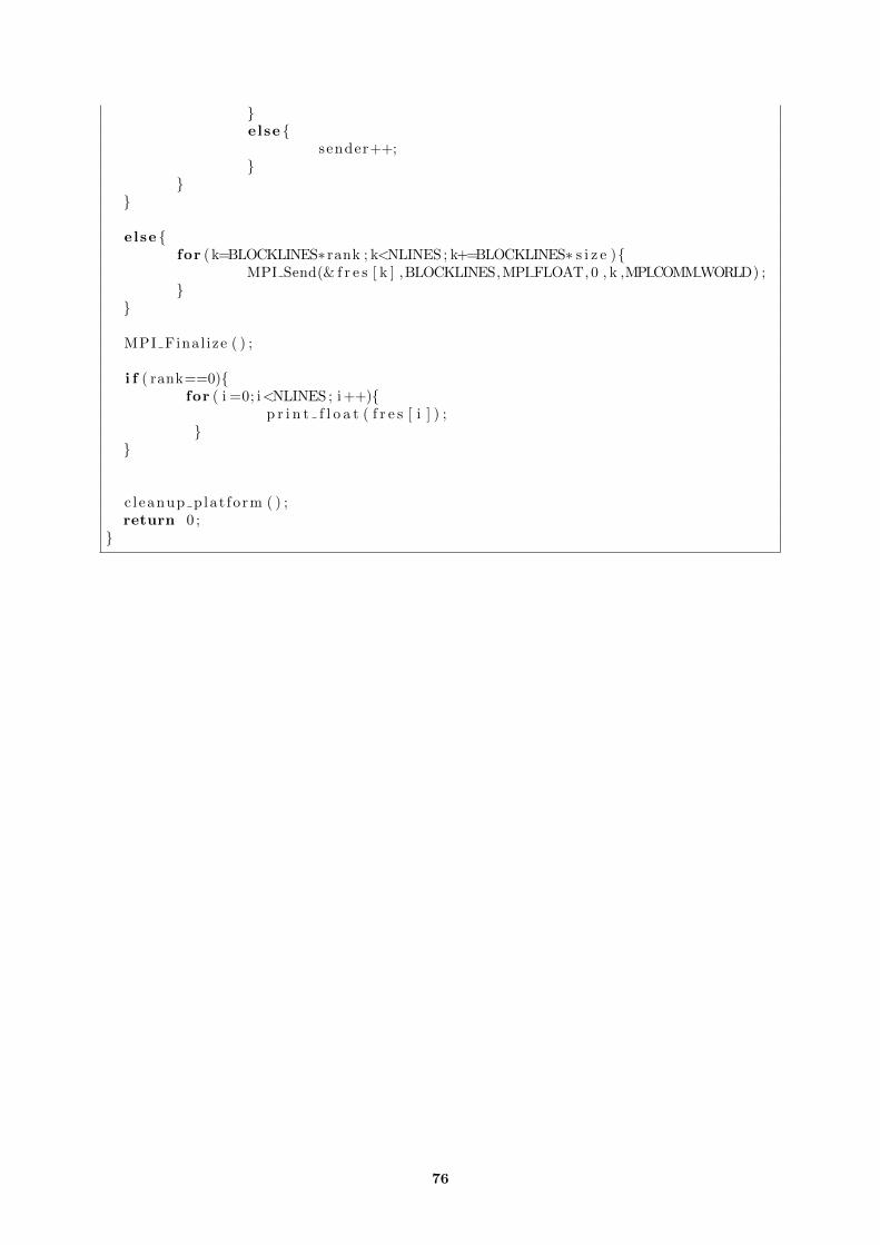
}else {
sender++;}
}}
else {for ( k=BLOCKLINES∗ rank ; k<NLINES ; k+=BLOCKLINES∗ s i z e ){
MPI Send(& f r e s [ k ] ,BLOCKLINES,MPI FLOAT, 0 , k ,MPI COMM WORLD) ;}
}
MPI Final ize ( ) ;
i f ( rank==0){for ( i =0; i<NLINES ; i ++){
p r i n t f l o a t ( f r e s [ i ] ) ;}
}
c l eanup p la t fo rm ( ) ;return 0 ;
}
76
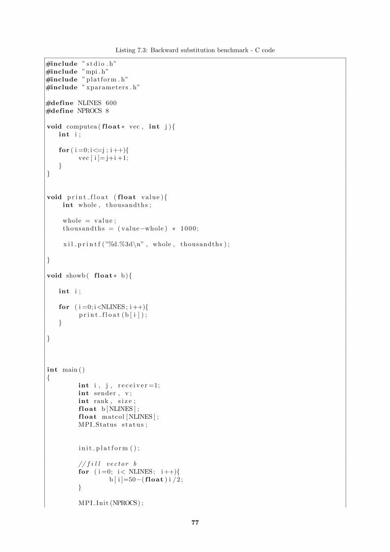
Listing 7.3: Backward substitution benchmark - C code
#include ” s t d i o . h”#include ”mpi . h”#include ” plat form . h”#include ” xparameters . h”
#define NLINES 600#define NPROCS 8
void computea ( f loat ∗ vec , int j ){int i ;
for ( i =0; i<=j ; i ++){vec [ i ]= j+i +1;
}}
void p r i n t f l o a t ( f loat value ){int whole , thousandths ;
whole = value ;thousandths = ( value−whole ) ∗ 1000 ;
x i l p r i n t f ( ”%d.%3d\n” , whole , thousandths ) ;
}
void showb ( f loat ∗ b){
int i ;
for ( i =0; i<NLINES ; i ++){p r i n t f l o a t (b [ i ] ) ;
}
}
int main ( ){
int i , j , r e c e i v e r =1;int sender , v ;int rank , s i z e ;f loat b [ NLINES ] ;f loat matcol [ NLINES ] ;MPI Status s t a t u s ;
i n i t p l a t f o r m ( ) ;
// f i l l v e c t o r bfor ( i =0; i< NLINES ; i ++){
b [ i ]=50−( f loat ) i /2 ;}
MPI Init (NPROCS) ;
77

MPI Comm rank(MPI COMM WORLD, &rank ) ;MPI Comm size (MPI COMM WORLD, &s i z e ) ;
i f ( rank==0){for ( i =1; i<NLINES ; i ++){
i f ( i%s i z e !=0){MPI Send(&b [ i ] , 1 ,MPI FLOAT, r e c e i v e r , i ,
MPI COMM WORLD) ;}i f ( r e c e i v e r==s i z e −1){
r e c e i v e r =0;}else {
r e c e i v e r ++;}
}}else {
for ( i=rank ; i<NLINES ; i+=s i z e ){MPI Recv(&b [ i ] , 1 ,MPI FLOAT, 0 , i ,MPI COMM WORLD,
&s t a t u s ) ;}
}// backsub
v=(NLINES%s i z e ==0)? s i z e −1:NLINES%s i z e −1;
for ( i=NLINES−1; i >=0; i−−){
i f ( rank==0){computea ( matcol , i ) ;
}MPI Bcast(&matcol [ 0 ] , i +1, MPI FLOAT, 0 , MPI COMM WORLD) ;i f ( rank==v ){
b [ i ]=b [ i ] / matcol [ i ] ;}
MPI Bcast(&b [ i ] , 1 , MPI FLOAT, v , MPI COMM WORLD) ;for ( j=rank ; j<i ; j+=s i z e ){
b [ j ]=b [ j ]−b [ i ]∗matcol [ j ] ;}
i f (v>0){v−−;
}else {
v=s i z e −1;}
}
// r e s u l t s ga theredsender =1;i f ( rank==0){
for ( i =1; i<NLINES ; i ++){i f ( i%s i z e !=0){
MPI Recv(&b [ i ] , 1 ,MPI FLOAT, sender , i ,
78
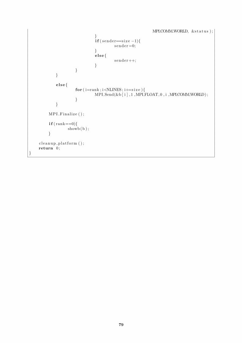
MPI COMM WORLD, &s t a t u s ) ;}i f ( sender==s i z e −1){
sender =0;}else {
sender++;}
}}
else {for ( i=rank ; i<NLINES ; i+=s i z e ){
MPI Send(&b [ i ] , 1 ,MPI FLOAT, 0 , i ,MPI COMM WORLD) ;}
}
MPI Final ize ( ) ;
i f ( rank==0){showb (b ) ;
}
c l eanup p la t fo rm ( ) ;return 0 ;
}
79
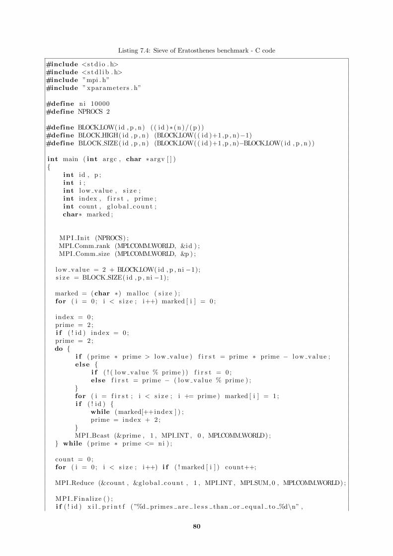
Listing 7.4: Sieve of Eratosthenes benchmark - C code
#include <s t d i o . h>#include <s t d l i b . h>#include ”mpi . h”#include ” xparameters . h”
#define ni 10000#define NPROCS 2
#define BLOCK LOW( id , p , n) ( ( id )∗ ( n )/ ( p ) )#define BLOCK HIGH( id , p , n) (BLOCK LOW( ( id )+1 ,p , n)−1)#define BLOCK SIZE( id , p , n ) (BLOCK LOW( ( id )+1 ,p , n)−BLOCK LOW( id , p , n ) )
int main ( int argc , char ∗argv [ ] ){
int id , p ;int i ;int low value , s i z e ;int index , f i r s t , prime ;int count , g l oba l count ;char∗ marked ;
MPI Init (NPROCS) ;MPI Comm rank (MPI COMM WORLD, &id ) ;MPI Comm size (MPI COMM WORLD, &p ) ;
low va lue = 2 + BLOCK LOW( id , p , ni −1);s i z e = BLOCK SIZE( id , p , ni −1);
marked = ( char ∗) mal loc ( s i z e ) ;for ( i = 0 ; i < s i z e ; i++) marked [ i ] = 0 ;
index = 0 ;prime = 2 ;i f ( ! id ) index = 0 ;prime = 2 ;do {
i f ( prime ∗ prime > l ow va lue ) f i r s t = prime ∗ prime − l ow va lue ;else {
i f ( ! ( l ow va lue % prime ) ) f i r s t = 0 ;else f i r s t = prime − ( low va lue % prime ) ;
}for ( i = f i r s t ; i < s i z e ; i += prime ) marked [ i ] = 1 ;i f ( ! id ) {
while ( marked[++index ] ) ;prime = index + 2 ;
}MPI Bcast (&prime , 1 , MPI INT , 0 , MPI COMM WORLD) ;
} while ( prime ∗ prime <= ni ) ;
count = 0 ;for ( i = 0 ; i < s i z e ; i++) i f ( ! marked [ i ] ) count++;
MPI Reduce (&count , &g loba l count , 1 , MPI INT , MPI SUM, 0 , MPI COMM WORLD) ;
MPI Final ize ( ) ;i f ( ! id ) x i l p r i n t f ( ”%d primes are l e s s than or equal to %d\n” ,
80

g loba l count , n i ) ;return 0 ;
}
81

82

83