distributed i/o system
TRANSCRIPT


Distributed I/O system
SIMATIC
ET 200SP Distributed I/O system
System Manual
05/2021 A5E03576849-AK
Preface
ET 200SP Documentation Guide
1
New properties/functions 2
System overview 3
Application planning 4
Installation 5
Wiring 6
Configuring 7
Basics of program execution
8
Protection 9
Configuration control (option handling)
10
Commissioning 11
Maintenance 12
Test and service functions 13
Technical specifications 14
Dimension drawings A
Accessories/spare parts B
Calculating the leakage resistance
C
Safety-relevant symbols D

Siemens AG Digital Industries Postfach 48 48 90026 NÜRNBERG GERMANY
A5E03576849-AK 05/2021 Subject to change
Copyright © Siemens AG 2012 - 2021. All rights reserved
Legal information Warning notice system
This manual contains notices you have to observe in order to ensure your personal safety, as well as to prevent damage to property. The notices referring to your personal safety are highlighted in the manual by a safety alert symbol, notices referring only to property damage have no safety alert symbol. These notices shown below are graded according to the degree of danger.
DANGER indicates that death or severe personal injury will result if proper precautions are not taken.
WARNING
indicates that death or severe personal injury may result if proper precautions are not taken.
CAUTION indicates that minor personal injury can result if proper precautions are not taken.
NOTICE
indicates that property damage can result if proper precautions are not taken. If more than one degree of danger is present, the warning notice representing the highest degree of danger will be used. A notice warning of injury to persons with a safety alert symbol may also include a warning relating to property damage.
Qualified Personnel The product/system described in this documentation may be operated only by personnel qualified for the specific task in accordance with the relevant documentation, in particular its warning notices and safety instructions. Qualified personnel are those who, based on their training and experience, are capable of identifying risks and avoiding potential hazards when working with these products/systems.
Proper use of Siemens products Note the following:
WARNING Siemens products may only be used for the applications described in the catalog and in the relevant technical documentation. If products and components from other manufacturers are used, these must be recommended or approved by Siemens. Proper transport, storage, installation, assembly, commissioning, operation and maintenance are required to ensure that the products operate safely and without any problems. The permissible ambient conditions must be complied with. The information in the relevant documentation must be observed.
Trademarks All names identified by ® are registered trademarks of Siemens AG. The remaining trademarks in this publication may be trademarks whose use by third parties for their own purposes could violate the rights of the owner.
Disclaimer of Liability We have reviewed the contents of this publication to ensure consistency with the hardware and software described. Since variance cannot be precluded entirely, we cannot guarantee full consistency. However, the information in this publication is reviewed regularly and any necessary corrections are included in subsequent editions.

Distributed I/O system
System Manual, 05/2021, A5E03576849-AK 3
Preface
Preface
Purpose of the documentation This documentation provides important information on configuring, installing, wiring and commissioning the ET 200SP distributed I/O system.
Basic knowledge required A basic knowledge of automation technology is required to understand the documentation.
Validity of the documentation This documentation applies to the distributed I/O system, ET 200SP.
Definition In this document, " motor starter" always refers to all variants of the ET 200SP motor starters.
Conventions Please pay particular attention to notes highlighted as follows:
Note
Notes contain important information on the product, handling the product or on part of the documentation to which you should pay particular attention.
Standards You can find a dated reference to the respective standards or the EC Declaration of Conformity on the Internet (https://support.industry.siemens.com)

Preface
Distributed I/O system
4 System Manual, 05/2021, A5E03576849-AK
Special information
WARNING
Hazardous Voltage Can Cause Death, Serious Injury, or Property Damage.
Proper use of hardware products
This equipment is only allowed to be used for the applications described in the catalog and in the technical description, and only in conjunction with non-Siemens equipment and components recommended by Siemens.
Correct transport, storage, installation and assembly, as well as careful operation and maintenance, are required to ensure that the product operates safely and without faults.
EU note: Start-up/commissioning is absolutely prohibited until it has been ensured that the machine in which the component described here is to be installed fulfills the regulations/specifications of Directive 2006/42/EC.
Note Important note for maintaining operational safety of your plant
Plants with safety-related features are subject to special operational safety requirements on the part of the operator. Even suppliers are required to observe special measures during product monitoring. For this reason, we inform you in the form of personal notifications about product developments and features that are (or could be) relevant to operation of systems from a safety perspective.
By subscribing to the appropriate notifications, you will ensure that you are always up-to-date and able to make changes to your system, when necessary.
Log onto Industry Online Support. Go to the following links and, on the side, right click on "email on update": • SIMATIC S7-300/S7-300F (https://support.industry.siemens.com/cs/ww/en/ps/13751) • SIMATIC S7-400/S7-400H/S7-400F/FH
(https://support.industry.siemens.com/cs/ww/en/ps/13828) • SIMATIC WinAC RTX (F) (https://support.industry.siemens.com/cs/ww/en/ps/13915) • SIMATIC S7-1500/SIMATIC S7-1500F
(https://support.industry.siemens.com/cs/ww/en/ps/13716) • SIMATIC S7-1200/SIMATIC S7-1200F
(https://support.industry.siemens.com/cs/ww/en/ps/13683) • Distributed I/O (https://support.industry.siemens.com/cs/ww/en/ps/14029) • STEP 7 (TIA Portal) (https://support.industry.siemens.com/cs/ww/en/ps/14667)
Note
When using F-CPUs in safety mode and fail-safe modules, observe the description of the SIMATIC Industrial Software SIMATIC Safety - Configuring and Programming (https://support.industry.siemens.com/cs/ww/de/view/54110126/en) fail-safe system.

Preface
Distributed I/O system
System Manual, 05/2021, A5E03576849-AK 5
Recycling and disposal For ecologically sustainable recycling and disposal of your old device, contact a certified disposal service for electronic scrap and dispose of the device in accordance with the regulations in your country.
Security information Siemens provides products and solutions with industrial security functions that support the secure operation of plants, systems, machines and networks.
In order to protect plants, systems, machines and networks against cyber threats, it is necessary to implement – and continuously maintain – a holistic, state-of-the-art industrial security concept. Siemens’ products and solutions constitute one element of such a concept.
Customers are responsible for preventing unauthorized access to their plants, systems, machines and networks. Such systems, machines and components should only be connected to an enterprise network or the internet if and to the extent such a connection is necessary and only when appropriate security measures (e.g. firewalls and/or network segmentation) are in place.
For additional information on industrial security measures that may be implemented, please visit (https://www.siemens.com/industrialsecurity).
Siemens' products and solutions undergo continuous development to make them more secure. Siemens strongly recommends that product updates are applied as soon as they are available and that the latest product versions are used. Use of product versions that are no longer supported, and failure to apply the latest updates may increase customers' exposure to cyber threats.
To stay informed about product updates, subscribe to the Siemens Industrial Security RSS Feed visit (https://www.siemens.com/industrialsecurity).

Preface
Distributed I/O system
6 System Manual, 05/2021, A5E03576849-AK
Siemens Industry Online Support You can find current information on the following topics quickly and easily here:
• Product support
All the information and extensive know-how on your product, technical specifications, FAQs, certificates, downloads, and manuals.
• Application examples
Tools and examples to solve your automation tasks – as well as function blocks, performance information and videos.
• Services
Information about Industry Services, Field Services, Technical Support, spare parts and training offers.
• Forums
For answers and solutions concerning automation technology.
• mySupport
Your personal working area in Industry Online Support for messages, support queries, and configurable documents.
This information is provided by the Siemens Industry Online Support in the Internet (https://support.industry.siemens.com).
Industry Mall The Industry Mall is the catalog and order system of Siemens AG for automation and drive solutions on the basis of Totally Integrated Automation (TIA) and Totally Integrated Power (TIP).
You can find catalogs for all automation and drive products on the Internet (https://mall.industry.siemens.com).

Distributed I/O system
System Manual, 05/2021, A5E03576849-AK 7
Table of contents
Preface ................................................................................................................................................... 3
1 ET 200SP Documentation Guide .......................................................................................................... 12
2 New properties/functions .................................................................................................................... 16
3 System overview ................................................................................................................................. 19
3.1 What is the SIMATIC ET 200SP distributed I/O system? ........................................................ 19
3.2 What are fail-safe automation systems and fail-safe modules? ............................................ 22
3.3 How are SIMATIC Safety F-systems structured with ET 200SP? ............................................ 23
3.4 Components ...................................................................................................................... 26
4 Application planning ........................................................................................................................... 37
4.1 Selecting the BaseUnit for I/O modules ............................................................................... 42 4.1.1 Digital, fail-safe, communication, technology or analog modules without temperature
measurement .................................................................................................................... 42 4.1.2 Analog modules with temperature measurement ............................................................... 43
4.2 Selecting motor starters with a suitable BaseUnit................................................................ 44 4.2.1 Selecting a BaseUnit for motor starters ............................................................................... 44 4.2.2 Selecting the motor starter ................................................................................................ 46 4.2.3 Selecting accessories for motor starters .............................................................................. 47
4.3 Selecting potential distributor modules .............................................................................. 48 4.3.1 Selecting a PotDis-BaseUnit ................................................................................................ 48 4.3.2 Selecting a PotDis-TerminalBlock ........................................................................................ 50
4.4 Hardware configuration ..................................................................................................... 51
4.5 Forming potential groups ................................................................................................... 53 4.5.1 Basics ................................................................................................................................ 53 4.5.2 Forming potential groups with BaseUnit type B1 ................................................................ 58 4.5.3 Forming potential groups with fail-safe modules ................................................................ 60 4.5.4 Forming potential groups with Ex modules ........................................................................ 61 4.5.5 Forming potential groups with motor starters .................................................................... 61
4.6 Configuration examples for potential groups ...................................................................... 64 4.6.1 Configuration examples with BaseUnits .............................................................................. 64 4.6.2 Configuration examples with potential distributor modules ................................................ 66
5 Installation ........................................................................................................................................... 68
5.1 Basics ................................................................................................................................ 68
5.2 Installation conditions for motor starters ............................................................................ 72
5.3 Mounting the CPU/interface module................................................................................... 74
5.4 Installing the CM DP communication module ..................................................................... 76
5.5 Mounting BaseUnits for I/O modules .................................................................................. 77

Table of contents
Distributed I/O system
8 System Manual, 05/2021, A5E03576849-AK
5.6 Mounting and dismantling BaseUnits for motor starters ..................................................... 80
5.7 Installing potential distributor modules .............................................................................. 82
5.8 Installing the server module ............................................................................................... 83
5.9 Mounting further accessories for motor starters ................................................................. 84 5.9.1 Mounting the cover for the 500 V AC infeed bus ................................................................ 84 5.9.2 Mounting the mechanical bracket for the BaseUnit ............................................................. 86 5.9.3 Mounting the BU cover ...................................................................................................... 89
6 Wiring .................................................................................................................................................. 90
6.1 Rules and regulations for operation .................................................................................... 90
6.2 Additional rules and regulations for the operation of the ET 200SP with fail-safe modules ............................................................................................................................ 93
6.2.1 Safety extra-low voltage (SELV, PELV) for failsafe modules and failsafe motor starters ......... 93 6.2.2 Requirements for sensors and actuators for fail-safe modules and fail-safe motor
starters .............................................................................................................................. 94 6.2.3 Crosstalk of digital input/output signals .............................................................................. 96
6.3 Additional rules and regulations for operation of an Ex module group ................................ 97
6.4 Additional rules and instructions for operation with motor starters ..................................... 97 6.4.1 Protection against short circuit ........................................................................................... 97
6.5 Operating the ET 200SP on grounded incoming supply....................................................... 98
6.6 Electrical configuration of the ET 200SP ........................................................................... 101
6.7 Wiring rules ..................................................................................................................... 104
6.8 Wiring BaseUnits for I/O modules ..................................................................................... 107
6.9 Connecting cable shields for I/O modules ......................................................................... 109
6.10 Wiring BaseUnits for motor starters .................................................................................. 112
6.11 Connecting the 3DI/LC module for the motor starter ......................................................... 115
6.12 Connecting the supply voltage to the CPU/interface module ............................................. 117
6.13 Connecting interfaces for communication ........................................................................ 119 6.13.1 Connecting PROFINET IO (port P3) to the CPU................................................................... 119 6.13.2 Connecting the PROFIBUS DP interface to the interface module/communications
module CM DP ................................................................................................................. 121
6.14 Inserting I/O modules / motor starters and BU covers ........................................................ 122
6.15 Mounting/disassembly of motor starters ........................................................................... 124 6.15.1 Mounting the fan............................................................................................................. 124 6.15.2 Mounting/disassembly of motor starters ........................................................................... 125 6.15.3 3DI/LC module ................................................................................................................. 127
6.16 Labeling ET 200SP ........................................................................................................... 130 6.16.1 Factory markings ............................................................................................................. 130 6.16.2 Optional markings ........................................................................................................... 132 6.16.3 Applying color identification labels ................................................................................... 134 6.16.4 Applying labeling strips .................................................................................................... 135 6.16.5 Applying reference identification labels ............................................................................ 136

Table of contents
Distributed I/O system
System Manual, 05/2021, A5E03576849-AK 9
7 Configuring ........................................................................................................................................ 137
7.1 Configuring ET 200SP ...................................................................................................... 137
7.2 Configuring the CPU ........................................................................................................ 140 7.2.1 Reading out the configuration .......................................................................................... 140 7.2.2 Addressing ...................................................................................................................... 143 7.2.3 Process images and process image partitions .................................................................... 145 7.2.3.1 Process image - overview ................................................................................................. 145 7.2.3.2 Automatically updating process image partitions .............................................................. 146 7.2.3.3 Update process image partitions in the user program ....................................................... 146
7.3 Configuring the interface module .................................................................................... 148
7.4 Value status ..................................................................................................................... 149
8 Basics of program execution ............................................................................................................. 151
8.1 Events and OBs ................................................................................................................ 151
8.2 Asynchronous instructions ............................................................................................... 153
9 Protection .......................................................................................................................................... 164
9.1 Overview of the protective functions of the CPU ............................................................... 164
9.2 Protection of confidential configuration data .................................................................... 165
9.3 Configuring access protection for the CPU ........................................................................ 165
9.4 Using the user program to set additional access protection ............................................... 168
9.5 Know-how protection ...................................................................................................... 169
9.6 Copy protection ............................................................................................................... 173
10 Configuration control (option handling) ........................................................................................... 175
10.1 Configuring ..................................................................................................................... 178
10.2 Creating the control data record ....................................................................................... 180 10.2.1 Introduction .................................................................................................................... 180 10.2.2 Control data record for an ET 200SP CPU .......................................................................... 182 10.2.3 Control data record for an interface module ..................................................................... 184 10.2.4 Feedback data record for interface modules ..................................................................... 188 10.2.5 Data records and functions .............................................................................................. 190
10.3 Transferring control data record in the startup program of the CPU ................................... 191
10.4 Behavior during operation ............................................................................................... 195
10.5 Examples of configuration control .................................................................................... 196
11 Commissioning .................................................................................................................................. 201
11.1 Overview ......................................................................................................................... 201
11.2 Commissioning the ET 200SP for PROFINET IO .................................................................. 203 11.2.1 ET 200SP CPU as an IO controller ...................................................................................... 203 11.2.2 ET 200SP CPU as an I-device ............................................................................................. 205 11.2.3 ET 200SP as an IO device .................................................................................................. 207

Table of contents
Distributed I/O system
10 System Manual, 05/2021, A5E03576849-AK
11.3 Commissioning the ET 200SP on PROFIBUS DP ................................................................. 208 11.3.1 ET 200SP as a DP master .................................................................................................. 208 11.3.2 ET 200SP as I-slave ........................................................................................................... 210 11.3.3 ET 200SP as a DP slave ..................................................................................................... 212
11.4 Startup of the ET 200SP with empty slots ......................................................................... 213
11.5 Removing/inserting a SIMATIC memory card on the CPU ................................................... 213
11.6 Operating modes of the CPU ............................................................................................ 215 11.6.1 STARTUP mode ................................................................................................................ 215 11.6.2 STOP mode ...................................................................................................................... 218 11.6.3 RUN mode ....................................................................................................................... 218 11.6.4 Operating mode transitions ............................................................................................. 219
11.7 CPU memory reset ........................................................................................................... 221 11.7.1 Automatic memory reset ................................................................................................. 222 11.7.2 Manual memory reset ...................................................................................................... 223
11.8 Reassigning parameters during operation ........................................................................ 224
11.9 Backing up and restoring the CPU configuration ............................................................... 225 11.9.1 Overview ......................................................................................................................... 225
11.10 Time synchronization ....................................................................................................... 228 11.10.1 Example: Configuring and changing NTP server ................................................................ 230
11.11 Identification and maintenance data ................................................................................ 232 11.11.1 Reading out and entering I&M data .................................................................................. 232 11.11.2 Data record structure for I&M data ................................................................................... 234 11.11.3 Example: Read out firmware version of the CPU with Get_IM_Data ................................... 236
11.12 Shared commissioning of projects .................................................................................... 238
12 Maintenance ...................................................................................................................................... 239
12.1 Removing and inserting I/O modules/motor starters (hot swapping) ................................. 239
12.2 Changing the type of an I/O module ................................................................................. 243
12.3 Replacing an I/O module .................................................................................................. 245
12.4 Replacing a motor starter ................................................................................................. 245
12.5 Replacing the terminal box on the BaseUnit ..................................................................... 246
12.6 Firmware update ............................................................................................................. 248
12.7 Resetting CPU/interface module (PROFINET) to factory settings ......................................... 255 12.7.1 Resetting the CPU to factory settings ................................................................................ 255 12.7.2 Resetting interface module (PROFINET IO) to factory settings ........................................... 258 12.7.3 Resetting the interface module (PROFINET IO) to factory settings with a RESET button ...... 260
12.8 Reaction to faults in fail-safe modules and fail-safe motor starters .................................... 261
12.9 Maintenance and repair ................................................................................................... 263
12.10 Warranty ......................................................................................................................... 263
13 Test and service functions ................................................................................................................. 264
13.1 Test functions .................................................................................................................. 264
13.2 Reading out/saving service data ....................................................................................... 270

Table of contents
Distributed I/O system
System Manual, 05/2021, A5E03576849-AK 11
14 Technical specifications ..................................................................................................................... 273
14.1 Standards, approvals and safety notes .............................................................................. 274
14.2 Electromagnetic compatibility .......................................................................................... 282
14.3 Electromagnetic compatibility of fail-safe modules ........................................................... 285
14.4 Shipping and storage conditions ...................................................................................... 288
14.5 Mechanical and climatic environmental conditions ........................................................... 288
14.6 Insulation, protection class, degree of protection and rated voltage .................................. 292
14.7 Use of the ET 200SP distributed I/O system in zone 2 potentially explosive atmospheres ... 294
A Dimension drawings .......................................................................................................................... 295
A.1 Shield connector .............................................................................................................. 295
A.2 Labeling strip ................................................................................................................... 295
A.3 Reference identification labels ......................................................................................... 296
B Accessories/spare parts ..................................................................................................................... 297
B.1 Lightning protection and overvoltage protection for fail-safe modules .............................. 301
C Calculating the leakage resistance .................................................................................................... 302
D Safety-relevant symbols .................................................................................................................... 304
D.1 Safety-related symbols for devices without Ex protection .................................................. 304
D.2 Safety-related symbols for devices with Ex protection ....................................................... 305
Glossary ............................................................................................................................................. 307
Index .................................................................................................................................................. 323

Distributed I/O system
12 System Manual, 05/2021, A5E03576849-AK
ET 200SP Documentation Guide 1
The documentation for the SIMATIC ET 200SP distributed I/O system is arranged into three areas. This arrangement enables you to access the specific content you require.
Basic information
The System Manual and Getting Started describe in detail the configuration, installation, wiring and commissioning of the SIMATIC ET 200SP distributed I/O system. The STEP 7 online help supports you in the configuration and programming.
Device information
Product manuals contain a compact description of the module-specific information, such as properties, wiring diagrams, characteristics and technical specifications.
General information
The function manuals contain detailed descriptions on general topics regarding the SIMATIC ET 200SP distributed I/O system, e.g. diagnostics, communication, Web server, motion control and OPC UA.
You can download the documentation free of charge from the Internet (https://support.industry.siemens.com/cs/ww/en/view/109742709).
Changes and supplements to the manuals are documented in a Product Information.
You can download the product information free of charge from the Internet (https://support.industry.siemens.com/cs/us/en/view/73021864).

ET 200SP Documentation Guide
Distributed I/O system
System Manual, 05/2021, A5E03576849-AK 13
Manual Collection ET 200SP The Manual Collection contains the complete documentation on the SIMATIC ET 200SP distributed I/O system gathered together in one file.
You can find the Manual Collection on the Internet (https://support.automation.siemens.com/WW/view/en/84133942).
"mySupport" With "mySupport", your personal workspace, you make the best out of your Industry Online Support.
In "mySupport", you can save filters, favorites and tags, request CAx data and compile your personal library in the Documentation area. In addition, your data is already filled out in support requests and you can get an overview of your current requests at any time.
You must register once to use the full functionality of "mySupport".
You can find "mySupport" on the Internet (https://support.industry.siemens.com/My/ww/en).
"mySupport" - Documentation With "mySupport", your personal workspace, you make the best out of your Industry Online Support.
In "mySupport", you can save filters, favorites and tags, request CAx data and compile your personal library in the Documentation area. In addition, your data is already filled out in support requests and you can get an overview of your current requests at any time.
You must register once to use the full functionality of "mySupport".
You can find "mySupport" on the Internet (https://support.industry.siemens.com/My/ww/en/documentation).
"mySupport" - CAx data In the CAx data area of "mySupport", you can access the latest product data for your CAx or CAe system.
You configure your own download package with a few clicks.
In doing so you can select:
• Product images, 2D dimension drawings, 3D models, internal circuit diagrams, EPLAN macro files
• Manuals, characteristics, operating manuals, certificates
• Product master data
You can find "mySupport" - CAx data on the Internet (https://support.industry.siemens.com/my/ww/en/CAxOnline).

ET 200SP Documentation Guide
Distributed I/O system
14 System Manual, 05/2021, A5E03576849-AK
Application examples The application examples support you with various tools and examples for solving your automation tasks. Solutions are shown in interplay with multiple components in the system - separated from the focus on individual products.
You will find the application examples on the Internet (https://support.industry.siemens.com/cs/ww/en/ps/ae).
TIA Selection Tool With the TIA Selection Tool, you can select, configure and order devices for Totally Integrated Automation (TIA). This tool is the successor of the SIMATIC Selection Tool and combines the known configurators for automation technology into one tool. With the TIA Selection Tool, you can generate a complete order list from your product selection or product configuration.
You can find the TIA Selection Tool on the Internet (https://support.industry.siemens.com/cs/ww/en/view/109767888).
SIMATIC Automation Tool You can use the SIMATIC Automation Tool to perform commissioning and maintenance activities simultaneously on various SIMATIC S7 stations as a bulk operation independent of TIA Portal.
The SIMATIC Automation Tool provides a multitude of functions:
• Scanning of a PROFINET/Ethernet system network and identification of all connected CPUs
• Address assignment (IP, subnet, gateway) and station name (PROFINET device) to a CPU
• Transfer of the date and the programming device/PC time converted to UTC time to the module
• Program download to CPU
• RUN/STOP mode switchover
• CPU localization by means of LED flashing
• Reading out of CPU error information
• Reading of the CPU diagnostics buffer
• Reset to factory settings
• Firmware update of the CPU and connected modules
You can find the SIMATIC Automation Tool on the Internet (https://support.industry.siemens.com/cs/ww/en/view/98161300).

ET 200SP Documentation Guide
Distributed I/O system
System Manual, 05/2021, A5E03576849-AK 15
PRONETA SIEMENS PRONETA (PROFINET network analysis) allows you to analyze the plant network during commissioning. PRONETA features two core functions:
• The topology overview automatically scans the PROFINET and all connected components.
• The IO check is a fast test of the wiring and the module configuration of a plant, incl. fail-safe inputs and outputs.
You can find SIEMENS PRONETA on the Internet (https://support.industry.siemens.com/cs/ww/en/view/67460624).
SINETPLAN SINETPLAN, the Siemens Network Planner, supports you in planning automation systems and networks based on PROFINET. The tool facilitates professional and predictive dimensioning of your PROFINET installation as early as in the planning stage. In addition, SINETPLAN supports you during network optimization and helps you to exploit network resources optimally and to plan reserves. This helps to prevent problems in commissioning or failures during productive operation even in advance of a planned operation. This increases the availability of the production plant and helps improve operational safety.
The advantages at a glance
• Network optimization thanks to port-specific calculation of the network load
• Increased production availability thanks to online scan and verification of existing systems
• Transparency before commissioning through importing and simulation of existing STEP 7 projects
• Efficiency through securing existing investments in the long term and the optimal use of resources
You can find SINETPLAN on the Internet (https://www.siemens.com/sinetplan).

Distributed I/O system
System Manual, 05/2021, A5E03576849-AK 16
New properties/functions 2
What's new in the ET 200SP System Manual, Edition 05/2021 compared to Edition 09/2019? What's new? What are the customer benefits? Where can I find information? New con-tents
Modules for hazardous area The Ex BaseUnits and Ex I/O modules enable the connection of intrinsically safe devices from the hazardous area Zone 0 and Zone 1.
(Page 19)System Manual ET 200SP HA Distributed I/O system / ET 200SP Modules for devices used in an explosion hazardous environment (https://support.industry.siemens.com/cs/ww/de/view/109795533/en) Starting from section System overview
What's new in the ET 200SP System Manual, Edition 09/2019 compared to Edition 02/2018 What's new? What are the customer benefits? Where can I find information? New con-tents
BaseUnits BU30-MS7, BU30-MS8, BU30-MS9 and BU30-MS10 for fail-safe motor starters
A simple, wire-saving group shutdown for fail-safe motor starters. In contrast to the earlier solution (BU30-MS5 and BU30-MS6), the fail-safe signal only has to be wired to the first motor starter. The fail-safe signal is internally routed via the Ba-seUnits.
Section Selecting motor start-ers with a suitable BaseUnit (Page 44) Section Forming potential groups (Page 53) Section Wiring BaseUnits for motor starters (Page 112)

New properties/functions
Distributed I/O system
System Manual, 05/2021, A5E03576849-AK 17
What's new in the system manual ET 200SP, edition 02/2018 compared to edition 12/2016 What's new? What are the customer benefits? Where can I find information? New con-tents
Potential distributor modules Potential distributor modules are a space-saving replacement for standard potential distributors or potential distributor terminals. You can set up potential groups much faster, in a more compact design and with fewer components than with standard potential distributor systems. One application is, for example, the design of digital input modules with 16 channels and 3-wire connection. By using the potential dis-tributor modules, you are reserving the un-used signal lines of antivalent sensors. Another application is the supply of potentials for external components.
Starting from section System overview (Page 19)
Password provider As an alternative to manual password input you can connect a password provider to STEP 7. A password provider offers the follow-ing advantages: • Convenient handling of passwords. STEP 7
reads the password automatically for the blocks. This saves you time.
• Optimal block protection because the operators do not know the actual pass-word.
Section Know-how protection (Page 169)
GetSMCinfo instruction With the help of the GetSMCinfo instruction you can respond to information provided by the memory card in the user program and if required, replace the memory card as a pre-cautionary measure. This makes sense in particular if you write to the card often in your application, for example if you use data logs.
Section AUTOHOTSPOT
Testing with breakpoints When testing with breakpoints, you execute a program from one breakpoint to another. Testing with breakpoints provides you with the following advantages: • Testing SCL and STL program code with
the help of breakpoints • Localization of logic errors step by step • Simple and quick analysis of complex
programs prior to actual commissioning • Recording of current values within indi-
vidual executed loops • Use of breakpoints for program validation
also possible in SCL/STL networks within LAD/FBD blocks
Section Test functions (Page 264)

New properties/functions
Distributed I/O system
18 System Manual, 05/2021, A5E03576849-AK
What's new? What are the customer benefits? Where can I find information? Changed contents
Reading out the identifica-tion and maintenance data using the Get_IM_Data in-struction
With the Get_IM_Data instruction you can read out the identification and maintenance data of the modules without much program-ming work. With the Get_IM_Data instruction, you can access the identification and maintenance data (I&M) of a module in the user program. I&M data is information saved in a module. This allows you to • check the system configurations • react to hardware changes • react to hardware faults in the user pro-
gram. Finding and elimination of hardware errors is made easier.
Section Reading out and enter-ing I&M data (Page 232)
Time synchronization For all applications that need the exact time, you update the CPU time using the NTP pro-cess. This also automatically sets the CPU time beyond subnet limits.
Section Time synchronization (Page 228)
Firmware update via accessi-ble devices
You are given information on fast firmware updates via accessible devices in the network.
Section Firmware update (Page 248)

Distributed I/O system
System Manual, 05/2021, A5E03576849-AK 19
System overview 3 3.1 What is the SIMATIC ET 200SP distributed I/O system?
SIMATIC ET 200SP SIMATIC ET 200SP is a scalable and highly flexible distributed I/O system for connecting process signals to a higher-level controller via a fieldbus.
Customer benefits of the system
Figure 3-1 SIMATIC ET 200SP distributed I/O system - Customer benefits

System overview 3.1 What is the SIMATIC ET 200SP distributed I/O system?
Distributed I/O system
20 System Manual, 05/2021, A5E03576849-AK
Area of application Thanks to its multifunctionality, the SIMATIC ET 200SP distributed I/O system is suitable for a wide range of applications. Its scalable design allows you to tailor your configuration to local requirements. Different CPUs/interface modules are available for connection to PROFINET IO. PROFIBUS DP, EtherNet/IP or Modbus TCP are available.
SIMATIC ET 200SP with CPU allows intelligent pre-processing to relieve the higher-level controller. The CPU can also be used as standalone device.
By using fail-safe CPUs, you can implement applications for safety engineering. Configuration and programming of your safety program takes place the same way as for standard CPUs.
A wide range of I/O modules rounds off the product range.
SIMATIC ET 200SP is designed with degree of protection IP20 and is intended for installation in a control cabinet.
Configuration The SIMATIC ET 200SP distributed I/O system is installed on a mounting rail. It consists of:
• CPU/interface module
• Up to 64 I/O modules, which can be plugged into BaseUnits in any combination
• Up to 31 motor starters
• A server module that completes the configuration of the ET 200SP.

System overview 3.1 What is the SIMATIC ET 200SP distributed I/O system?
Distributed I/O system
System Manual, 05/2021, A5E03576849-AK 21
Configuration example
① BusAdapter ② Mounting rail ③ Reference identification label ④ CPU/interface module ⑤ Light-colored BaseUnit BU..D with infeed of supply voltage ⑥ Dark-colored BaseUnits BU..B for conducting the potential group further ⑦ BaseUnit for motor starters ⑧ Potential distributor module ⑨ Ex BaseUnit for Ex power module ⑩ Ex BaseUnit for Ex I/O module ⑪ Server module (included in the scope of supply of the CPU/interface module) ⑫ Ex I/O module ⑬ Ex power module ⑭ ET 200SP motor starter ⑮ I/O module
Figure 3-2 Configuration example of the ET 200SP

System overview 3.2 What are fail-safe automation systems and fail-safe modules?
Distributed I/O system
22 System Manual, 05/2021, A5E03576849-AK
3.2 What are fail-safe automation systems and fail-safe modules?
Fail-safe automation systems Fail-safe automation systems (F-systems) are used in systems with higher safety requirements. F-systems control processes and ensure that they are in a safe state immediately after shutdown. In other words, F-systems control processes in which an immediate shutdown does not endanger persons or the environment.
Safety Integrated Safety Integrated is the integrated safety concept for automation and drive technology from Siemens.
Proven technologies and systems from automation technology are used for safety systems. Safety Integrated includes the complete safety sequence, ranging from sensor, actuator and fail-safe modules right through to the controller, including safety-related communication via standard fieldbuses. Drives and controllers handle safety tasks in addition to their actual functions.
Fail-safe modules The key difference between fail-safe modules (F-modules) and standard modules is that they have an internal two-channel design. This means the two integrated processors monitor each other, automatically test the input and output circuits, and switch the fail-safe module to a safe state in the event of a fault.
The F-CPU communicates with a fail-safe module via the safety-related PROFIsafe bus profile.
Fail-safe motor starters Fail-safe motor starters enable safety-related tripping of motor loads. Fail-safe motor starters are not PROFIsafe nodes. Motor starters operate together with the fail-safe modules of the ET 200SP system.
Area of application of ET 200SP with fail-safe I/O modules By using the ET 200SP distributed I/O system with fail-safe I/O modules, you are replacing conventional safety engineering configurations. This includes the replacement of switching devices for emergency STOP, protective door monitors, two-hand operation, etc.

System overview 3.3 How are SIMATIC Safety F-systems structured with ET 200SP?
Distributed I/O system
System Manual, 05/2021, A5E03576849-AK 23
3.3 How are SIMATIC Safety F-systems structured with ET 200SP?
SIMATIC Safety F-system with ET 200SP The figure below shows an example of a configuration for a SIMATIC Safety F-system with ET 200SP distributed I/O system and PROFINET IO. The PROFINET IO lines can be set up with copper cable, fiber-optic cable or WLAN.
Fail-safe I/O modules and non-fail-safe I/O modules can be combined in an ET 200SP configuration.
The fail-safe IO controller (F-CPU) exchanges safety-related and non-safety-related data with fail-safe and non-fail-safe ET 200SP modules.
Figure 3-3 Fail-safe SIMATIC Safety automation system (sample configuration)
Fail-safe ET 200SP I/O modules The following fail-safe I/O modules are available for the ET 200SP distributed I/O system:
• Fail-safe power modules are used to supply the potential group load voltage and for the safety-related tripping of the load voltage for non-fail-safe output modules.
• Fail-safe digital input modules detect the signal states of safety-related sensors and send the relevant safety frames to the F-CPU.
• Fail-safe digital output modules are suitable for safety-related shutdown procedures with short circuit and cross-circuit protection up to the actuator.
ET 200SP fail-safe motor starters Fail-safe motor starters are suitable for safety-related tripping of motor loads.

System overview 3.3 How are SIMATIC Safety F-systems structured with ET 200SP?
Distributed I/O system
24 System Manual, 05/2021, A5E03576849-AK
Example of a configuration with fail-safe I/O modules
① Interface module ② Light-colored BaseUnit BU..D with infeed of supply voltage ③ Dark-colored BaseUnits BU..B for conducting the potential group further ④ I/O module ⑤ Server module (ships with the interface module) ⑥ Fail-safe I/O modules ⑦ BusAdapter ⑧ Mounting rail ⑨ Reference identification label
Figure 3-4 Example of a configuration of the ET 200SP with fail-safe I/O modules

System overview 3.3 How are SIMATIC Safety F-systems structured with ET 200SP?
Distributed I/O system
System Manual, 05/2021, A5E03576849-AK 25
Hardware and software requirements Fail-safe modules ET 200SP are supported by IM155-6PN ST interface modules as of firmware V1.1.1, IM155-6PN HF as of firmware V2.0, IM155-6PN HS as of firmware V4.0 and IM155-6DP HF as of firmware V1.0.
You require the STEP 7 Safety Advanced option package, V12 or higher including HSP 54, for configuration and programming of the ET 200SP fail-safe modules with the SIMATIC Safety fail-safe system.
You require the F-Configuration Pack V5.5 SP10 or later for configuring and programming the ET 200SP failsafe modules with the Distributed Safety failsafe system.
You require the F-Configuration Pack V5.5 SP12 or later for configuring and programming the ET 200SP failsafe modules with the F/FH Systems failsafe system.
ET 200SP fail-safe motor starters are supported by interface modules IM155-6PN BA, firmware V3.2 or higher, IM155-6PN ST, firmware V3.1 or higher, IM155-6PN HF, firmware V3.1 or higher and IM155-6DP HF firmware V3.0 or higher.
You require SIMATIC Step 7 V14 or higher for configuration and programming of ET 200SP fail-safe motor starters. The F-Configuration Pack is not needed for configuration and programming of the ET 200SP fail-safe motor starter.
Note
Configuration of ET 200SP motor starters, SIMATIC Step 7 V13 or higher, is possible with a GSD file (GSDML).
Use in safety mode only Safety mode is the F-I/O operating mode that allows safety-related communication using safety frames.
Safety mode of motor starters is characterized by the fail-safe digital input (F-DI) and availability of the 24 V power supply.
You can only use the ET 200SP fail-safe I/O modules in safety mode. They cannot be used in non-fail-safe mode.
System overview 3.4 Components
Distributed I/O system
26 System Manual, 05/2021, A5E03576849-AK
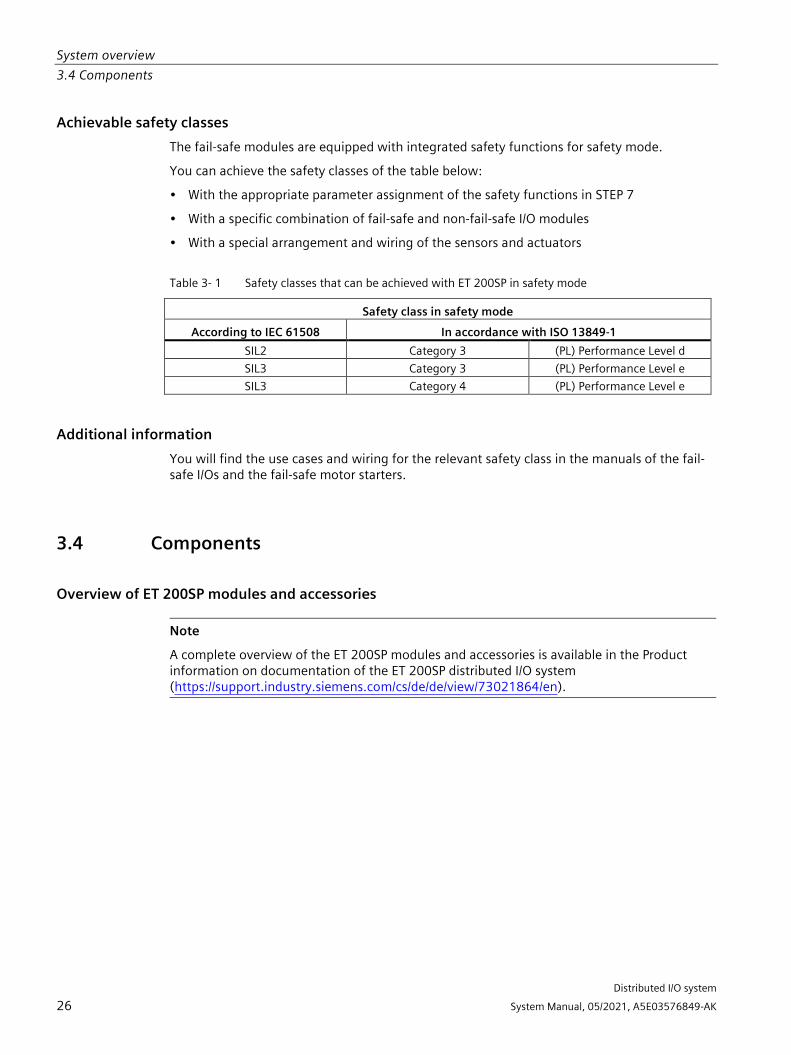
Achievable safety classes The fail-safe modules are equipped with integrated safety functions for safety mode.
You can achieve the safety classes of the table below:
• With the appropriate parameter assignment of the safety functions in STEP 7
• With a specific combination of fail-safe and non-fail-safe I/O modules
• With a special arrangement and wiring of the sensors and actuators
Table 3- 1 Safety classes that can be achieved with ET 200SP in safety mode
Safety class in safety mode According to IEC 61508 In accordance with ISO 13849-1
SIL2 Category 3 (PL) Performance Level d SIL3 Category 3 (PL) Performance Level e SIL3 Category 4 (PL) Performance Level e
Additional information You will find the use cases and wiring for the relevant safety class in the manuals of the fail-safe I/Os and the fail-safe motor starters.
3.4 Components
Overview of ET 200SP modules and accessories
Note
A complete overview of the ET 200SP modules and accessories is available in the Product information on documentation of the ET 200SP distributed I/O system (https://support.industry.siemens.com/cs/de/de/view/73021864/en).

System overview 3.4 Components
Distributed I/O system
System Manual, 05/2021, A5E03576849-AK 27
Basic components of the ET 200SP distributed I/O system
Table 3- 2 Basic components of the ET 200SP
Basic component Function Figure Mounting rail in accord-ance with EN 60715
The mounting rail is the rack of the ET 200SP distributed I/O system. The ET 200SP is installed on the mounting rail. The mounting rail is 35 mm high.
CPU/Fail-safe CPU The (F) CPU: • Runs the user program. The F-CPU also runs
the safety program. • Can be used as an IO controller or I-Device on
PROFINET IO or as a standalone CPU • Links the ET 200SP to the IO devices or the IO
controller • Exchanges data with the I/O modules via the
backplane bus. Additional CPU functions: • Communication via PROFIBUS DP (the CPU
can be used as a DP master or DP slave in combination with the CM DP communication module)
• Integrated Web server • Integrated technology • Integrated trace functionality • Integrated system diagnostics • Integrated safety • Safety mode (when using fail-safe CPUs)
Communication module CM DP
The communication module CM DP • Connects the CPU with PROFIBUS DP • The bus connection is an RS485 interface

System overview 3.4 Components
Distributed I/O system
28 System Manual, 05/2021, A5E03576849-AK
Basic component Function Figure Interface module for PROFINET IO
The interface module: • Can be used as IO device on PROFINET IO • Links the ET 200SP with the IO controller • Exchanges data with the I/O modules via the
backplane bus.
Interface module for MultiFieldbus
The interface module: • Use as IO device on PROFINET IO • Links the ET 200SP with the IO controller • Links the ET 200SP via EtherNet/IP • Links the ET 200SP via Modbus TCP • Exchanges data with the I/O modules via the
backplane bus. You can find more information about Multi-Fieldbus in the Interface module IM 155-6 MF HF Equipment Manual (https://support.industry.siemens.com/cs/ww/en/view/109773210).
Interface module for PROFIBUS DP
The interface module: • Can be used as DP slave on PROFIBUS DP • Links the ET 200SP with the DP master • Exchanges data with the I/O modules via the
backplane bus.

System overview 3.4 Components
Distributed I/O system
System Manual, 05/2021, A5E03576849-AK 29
Basic component Function Figure BusAdapter The BusAdapters allow free selection of the con-
nection technology for PROFINET IO. The follow-ing versions are available for PROFINET CPU/interface modules: • For standard RJ45 connector (BA 2×RJ45) ① • For direct connection of the bus cable
(BA 2×FC) ② • For standard M12 connector (D-coded) with
screw-type terminal or plug-in push-pull ver-sion (BA 2xM12) ③
• For POF/PCF fiber-optic cable (BA 2xSCRJ) ④ • As media converter for POF/PCF fiber-optic
cable ⇔ standard RJ45 plug (BA SCRJ/RJ45) ⑤
• As media converter for POF/PCF fiber-optic cable ⇔ direct connection of the bus cable (BA SCRJ/FC) ⑥
• For glass fiber-optic cable (BA 2xLC) ⑦ • As media converter for glass fiber-optic cable
⇔ standard RJ45 plug (BA LC/RJ45) ⑧ • As media converter for glass fiber-optic cable
⇔ direct connection of the bus cable (BA LC/FC) ⑨
For mixed ET 200SP/ET 200AL configuration, you require the BusAdapter BA-Send 1xFC ① (plugged into the BaseUnit BU-Send). Connect the bus cable for ET-Connection to the BusAdapter BA-Send 1xFC.

System overview 3.4 Components
Distributed I/O system
30 System Manual, 05/2021, A5E03576849-AK
Basic component Function Figure BaseUnit The BaseUnits provide the electrical and mechan-
ical connection of the ET 200SP modules. Place the I/O modules or the motor starter onto the BaseUnits. Suitable BaseUnits are available in each case for the different requirements. You can find addi-tional information in section Selecting the Ba-seUnit for I/O modules (Page 42).
Ex BaseUnit You need the following BaseUnits for an Ex module group: • Ex BaseUnit for Ex power module • Ex BaseUnit for Ex I/O module
PotDis-BaseUnit poten-tial distributor module
You use the potential distributor module to dis-tribute a variety of potentials (P1, P2). This al-lows you to implement a multi-cable connection without external terminals with 16-channel digi-tal modules. The assembly has two parts: • If you need additional potential terminals,
plug a PotDis-TerminalBlock in the PotDis-BaseUnit.
• Alternatively, plug a BU cover (15 mm) on the PotDis-BaseUnit.
With potential distributor modules, you may only connect to the PotDis-TB versions BR-W and n.c.-G potential, which exceed the voltage level of SELV/PELV. Other SELV/PELV potential groups should be separated with light-colored PotDis BUs. Suitable PotDis-BaseUnits are available in each case for the different requirements. You can find additional information in section Selecting a PotDis-BaseUnit (Page 48).

System overview 3.4 Components
Distributed I/O system
System Manual, 05/2021, A5E03576849-AK 31
Basic component Function Figure PotDis-TerminalBlock If you need additional potential terminals for a
PotDis-BaseUnit, plug a PotDis-TerminalBlock in the PotDis-BaseUnit. Voltages greater than SELV/PELV are only permit-ted for the PO PotDis-TBs BR (bridged) and NC (not connected). The same applies to PE. Voltag-es at the terminals of the PotDis modules con-nected to the P1/P2 rails must not be greater than SELV/PELV. Suitable PotDis-TerminalBlocks are available in each case for the different requirements. You can find additional information in section Select-ing a PotDis-TerminalBlock (Page 50).
Fail-safe power module The fail-safe power module allows the safety-related shutdown of digital output modules / fail-safe digital output modules.
Ex power module The Ex power module supplies the downstream Ex I/O modules via the power bus on the Ex Ba-seUnit of the Ex power module. An Ex BaseUnit is required for installing the Ex power module.
I/O module / Fail-safe I/O module/ Ex I/O module
The I/O module determines the function at the terminals. The controller detects the current process state via the connected sensors and actuators, and triggers the corresponding reac-tions. I/O modules are divided into the following module types: • Digital input (DI, F-DI, Ex-DI) • Digital output (DQ, F-DQ PM, F-DQ PP, F-RQ,
Ex-DQ) • Analog input (AI, F-AI, Ex-AI) • Analog output (AQ, Ex-AQ) • Technology module (TM, F-TM-C) • Communication module (CM) • Power module (F-PM-E)

System overview 3.4 Components
Distributed I/O system
32 System Manual, 05/2021, A5E03576849-AK
Basic component Function Figure Motor starter/fail-safe motor starter
The motor starter is a switching and protection device for 1-phase and 3-phase loads. The motor starter is available as a direct-on-line and reversing starter.
Vale terminal AirLINE SP type 8647 (Bürkert GmbH & Co. KG) 1) 2)
Basic component: Valve terminal AirLINE SP type 8647 (Bürkert). For more information on the AirLINE SP, type 8647 (e.g. data sheet and operating instruc-tions), please contact Bürkert (https://www.burkert.co.uk/en/type/8647) direct-ly. Function: Valve terminals are common in industrial auto-mation and are used as pilot valves for control-ling pneumatic actuators, for example in areas of the food, pharmaceutical and water treatment industries. The ET 200SP in combination with the AirLINE SP, type 8647 from Bürkert provides a universal interface between process and plant control that enables the flexible, modular con-figuration of pilot valves and I/O modules. The valve terminal can also be fitted to the base of the control cabinet with the help of the AirLINE Quick Adapter. This further reduces the space required in the control cabinet and considerably simplifies installation of the pneumatic system. 1) 2)

System overview 3.4 Components
Distributed I/O system
System Manual, 05/2021, A5E03576849-AK 33
Basic component Function Figure BU cover Insert the BU cover on the BaseUnits:
• Whose slots are not equipped with I/O mod-ules/ motor starters//PotDis-TerminalBlocks.
• Whose slots have been reserved for future expansion (as empty slots).
You can keep a reference identification label for the planned I/O module inside the BU cover. There are three versions: • For BaseUnits with a width of 15 mm ① • For BaseUnits/Ex BaseUnits with a width of
20 mm ② • For BaseUnits of motor starters with a width
of 30 mm ③
Server module The server module completes the configuration of the ET 200SP. The server module includes holders for 3 spare fuses (5 × 20 mm). The server module ships with the CPU/interface module and is available as spare part.

System overview 3.4 Components
Distributed I/O system
34 System Manual, 05/2021, A5E03576849-AK
Basic component Function Figure Coding element The coding element codes the I/O module with
the BaseUnit. There are two versions: • Mechanical coding element ①: Ensures the
coding • Electronic coding element ②: This version
also has an electronic, rewritable memory for module-specific configuration data (such as the F-destination address for fail-safe mod-ules, parameter data for the IO link master).
1) Note: The description contains non-binding information on supplementary products that are manufactured and market-ed not by Siemens but by third-parties outside the Siemens group ("third-party firms"). These third parties organize the manufacture, sale and delivery of their products independently and their terms and conditions apply. Responsibility for these supplementary products and for the information relating to them that is provided here thus lies solely with the third parties in question. Unless bound to do so by statutory requirements, Siemens shall not accept any liability or provide any guarantee for the supplementary products of third-party firms. Please also note the information "Disclaimer/Use of hyperlinks".
2) Disclaimer/Use of hyperlinks: Siemens has put together this description with great care. However, Siemens is unable to check whether the data provided by third-party firms is complete, accurate and up to date. Certain items of information may therefore potentially be incorrect, incomplete or no longer up to date. Siemens shall not accept any liability should this be the case, nor shall it accept liability for the usability of the data or of the product for the user unless it has a statu-tory obligation to do so. This entry contains the addresses of third-party websites. Siemens is not responsible for and shall not be liable for these websites or their content, as Siemens has not checked the information contained therein and is not responsible for the content or information they provide. The use of such websites is at the user's own risk.

System overview 3.4 Components
Distributed I/O system
System Manual, 05/2021, A5E03576849-AK 35
Accessories of the ET 200SP distributed I/O system
Table 3- 3 Accessories of the ET 200SP
Accessories Function Figure 24 V DC connector Applying the 24 V DC supply at the connector
and connection with the CPU/interface mod-ule/Ex power module. The 24 V DC connector is available as spare part.
Shield connection The shield connection allows the low-impedance contacting of cable shields with minimum installation times.
Labeling strips Attach the labeling strips to the modules for system-specific labeling of the ET 200SP dis-tributed I/O system. The labeling strips can be printed. The labeling strips can be ordered as accesso-ries (Page 297) on a roll for thermal transfer printers or as DIN A4 format sheets for laser printers.
Reference identification labels
The labels enable the reference identification labeling of the ET 200SP components. The labels can be ordered on a mat for thermal transfer and inkjet printers as accessories (Page 297).
Color identification labels The color identification labels are module-specific and can be ordered for the process terminals, AUX terminals and additional termi-nals as accessories (Page 297).

System overview 3.4 Components
Distributed I/O system
36 System Manual, 05/2021, A5E03576849-AK
Accessories of the SIMATIC ET 200SP motor starters
Table 3- 4 SIMATIC ET 200SP motor starter accessories
Accessories Function Figure 3DI/LC module The optional 3DI/LC module has three digital
inputs and one LC input. For reasons of opera-tional safety, input LC is permanently set to manual local mode. By parameterizing the inputs DI1 - DI3 with motor CLOCKWISE or motor COUNTER-CLOCKWISE, you can control the motor in manual local mode. The functions of the 3DI/LC module are not relevant to functional safety. Detailed information on the functions when using a 3DI/LC module can be found in the Manual (https://support.industry.siemens.com/cs/ww/en/view/109479973).
Mechanical bracket for BaseUnit
Use the mechanical bracket for additional fixing of the motor starter. You can use the mechanical bracket on 7.5 mm and 15 mm mounting rails.
Infeed bus cover For finger-safe termination of the infeed bus, use the cover.
Fan You can use the motor starter at higher ambi-ent temperatures if a fan is installed.

Distributed I/O system
System Manual, 05/2021, A5E03576849-AK 37
Application planning 4
Overview The BaseUnits (BU) are classified according to different types. Every BaseUnit type is distinguished by characteristics that match certain I/O modules and motor starters (see the following table and graphics).
You recognize the BU type for an I/O module by the last two digits of an I/O module's article number.
The BU type onto which you can plug the respective I/O module is printed on the I/O modules. You can therefore read which BU type you need straight from the I/O module (see Factory labels (Page 130) (page 122)). Example: On the output module DQ 16x24VDC/0.5A ST with article number 6ES7132-6BH01-0BA0 the information "BU: A0" is printed. This means you can plug this I/O module into a BaseUnit of BU type "A0", which means any BaseUnit whose article number ends in "A0". I/O modules that are suitable for two BU types are labeled accordingly, for example "BU: A0, A1".
Note
You will find a complete module overview of the ET 200SP distributed I/O system and an overview of possibilities of combining BaseUnits and I/O modules /motor starters in the Product information for documentation of the ET 200SP distributed I/O system (https://support.industry.siemens.com/cs/de/de/view/73021864/en).
Note Use of Ex modules
If you are using Ex I/O modules for the connection of intrinsically safe devices from Zone 0 or Zone 1 in the ET 200SP configuration, observe the information for plant planning in the System Manual ET 200SP HA Distributed I/O system / ET 200SP Modules for devices used in an explosion hazardous environment (https://support.industry.siemens.com/cs/ww/de/view/109795533/en).

Application planning
Distributed I/O system
38 System Manual, 05/2021, A5E03576849-AK
Table 4- 1 Selecting a suitable BaseUnit for I/O modules
Selecting a BaseUnit I/O module (example)
Examples of suitable I/O modules for BU types
I/O module (example) BaseUnit BU type A0 See Digital, fail-safe, communication, technology or analog modules without temperature meas-urement (Page 42)
Digital, fail-safe, technology or com-munication module • 6ES7...A0 • 24 V DC • 15 mm wide
DI 16×24VDC ST (6ES7131-6BH00-0BA0)
BU15-P16+A0+2D (6ES7193-6BP00-0DA0)
BU type A1 See Analog modules with temperature measurement (Page 43)
Analog module with temperature meas-urement* • 6ES7...A1 • 24 V DC • 15 mm wide
AI 4×RTD/TC 2-/3-/4-wire HF (6ES7134-6JD00-0CA1)
BU15-P16+A0+2D/T(6ES7193-6BP00-0DA1)
Analog module with-out temperature measurement** • 6ES7...A1 • 24 V DC • 15 mm wide
AI 4xU/I 2-wire ST (6ES7134-6HD00-0BA1)
BU type B0 (BU..B, dark-colored BaseUnit)
Digital output module with relay • 6ES7...B0 • Up to 230 V AC • 20 mm wide
RQ 4×120VDC-230VAC/5A NO ST (6ES7132-6HD00-0BB0)
BU20-P12+A4+0B (6ES7193-6BP20-0BB0)
BU type B1 (BU..B, dark-colored BaseUnit)
Digital modules • 6ES7...B1 • Up to 230 V AC • 20 mm wide
DI 4×120..230VAC ST (6ES7131-6FD00-0BB1)
BU20-P12+A0+4B (6ES7193-6BP20-0BB1)
BU type C0 (BU..D, light-colored BaseUnit)
Fail-safe power mod-ule • 6ES7...C0 • 24 V DC • 20 mm wide CM AS-i Master ST/F-CM AS-i Safety ST • 6ES7...C1 • Up to 30 V DC • 20 mm wide
CM AS-i Master ST (3RK7137-6SA00-0BC1)
BU20-P6+A2+4D (6ES7193-6BP20-0DC0)

Application planning
Distributed I/O system
System Manual, 05/2021, A5E03576849-AK 39
Selecting a BaseUnit I/O module (example)
Examples of suitable I/O modules for BU types
I/O module (example) BaseUnit BU type C1 (BU..B, dark-colored BaseUnit)
F-CM AS-i Safety ST • 6ES7...C1 • Up to 30 V DC • 20 mm wide
F-CM AS-i Safety ST (3RK7136-6SC00-0BC1)
BU20-P6+A2+4B (6ES7193-6BP20-0BC1)
BU type D0 AI Energy Meter • 6ES7...D0 • Up to 400 V AC/
480 V AC • 20 mm wide
AI Energy Meter 480VAC ST (6ES7134-6PA20-0BD0)
BU20-P12+A0+0B (6ES7193-6BP00-0BD0)
BU type F0 F-RQ 1×24VDC/24..230VAC/5A • 6ES7...F0 • Up to 230 V AC • 20 mm wide
F-RQ 1×24VDC/24..230VAC/5A (6ES7136-6RA00-0BF0)
BU20-P8+A4+0B (6E7193-6BP20-0BF0)
BU type U0 DQ 4×24...230VAC/2A HF • 6ES7...U0 • Up to
400 V AC/480 V AC
• 20 mm wide
DQ 4×24...230VAC/2A HF (6ES7132-6FD00-0CU0)
BU20-P16+A0+2D (6E7193-6BP00-0BU0)
* For compensation of the reference junction temperature for thermocouples. BU type A1 is required if you measure the reference junction temperature with an internal temperature sensor or if you need the additional 2×5 terminals. If you use the internal reference junction temperature with BU type A1, ensure an even tempera-ture distribution at the terminals. The specified accuracy of the utilized analog module is then ad-hered to. If necessary, you can increase the accuracy via user calibration.
** Analog modules with and without temperature measurement can also be plugged into BU type A0.

Application planning
Distributed I/O system
40 System Manual, 05/2021, A5E03576849-AK
Table 4- 2 BaseUnit for motor starters
Selecting the BaseUnit BU-30-MS1
BU-30-MS2
BU-30-MS3
BU-30-MS4
BU-30-MS5
BU-30-MS6
BU-30-MS7
BU-30-MS8
BU-30-MS9
BU-30-MS10
24 V infeed x x 500 V infeed x x x x x F-DI terminals (no routing of the F-DI signal possible)
x x
F-DI infeed x x F-DI routing x x Motor starters DS 0.1 - 0.4 A HF
3RK1308-0AA00-0CP0
x x x x x* x* x* x* x* x*
DS 0.3 - 1A HF
3RK1308-0AB00-0CP0
x x x x x* x* x* x* x* x*
DS 0.9 - 3A HF
3RK1308-0AC00-0CP0
x x x x x* x* x* x* x* x*
DS 2.8 - 9A HF
3RK1308-0AD00-0CP0
x x x x x* x* x* x* x* x*
DS 4.0 - 12A HF
3RK1308-0AE00-0CP0
x x x x x* x* x* x* x* x*
RS 0.1 - 0.4 A HF
3RK1308-0BA00-0CP0
x x x x x* x* x* x* x* x*
RS 0.3 - 1A HF
3RK1308-0BB00-0CP0
x x x x x* x* x* x* x* x*
RS 0.9 - 3A HF
3RK1308-0BC00-0CP0
x x x x x* x* x* x* x* x*
RS 2.8 - 9A HF
3RK1308-0BD00-0CP0
x x x x x* x* x* x* x* x*
RS 4.0 - 12A HF
3RK1308-0BE00-0CP0
x x x x x* x* x* x* x* x*
F-DS 0.1 - 0.4 A HF
3RK1308-0CA00-0CP0
x x x x x x x x x x
F-DS 0.3 - 1A HF
3RK1308-0CB00-0CP0
x x x x x x x x x x
F-DS 0.9 - 3A HF
3RK1308-0CC00-0CP0
x x x x x x x x x x
F-DS 2.8 - 9A HF
3RK1308-0CD00-0CP0
x x x x x x x x x x
F-DS 4.0 - 12A HF
3RK1308-0CE00-0CP0
x x x x x x x x x x
F-RS 0.1 - 0.4 A HF
3RK1308-0DA00-0CP0
x x x x x x x x x x
F-RS 0.3 - 1A HF
3RK1308-0DB00-0CP0
x x x x x x x x x x
F-RS 0.9 - 3A HF
3RK1308-0DC00-0CP0
x x x x x x x x x x

Application planning
Distributed I/O system
System Manual, 05/2021, A5E03576849-AK 41
F-RS 2.8 - 9A HF
3RK1308-0DD00-0CP0
x x x x x x x x x x
F-RS 4.0 - 12A HF
3RK1308-0DE00-0CP0
x x x x x x x x x x
* The F-DI terminals or F-DI infeed/routing have no function with this combination.
Additional information Additional information on the functional assignment of the terminals and on the associated BaseUnits can be found in one of the following manuals:
• Manual for the relevant I/O module (https://support.industry.siemens.com/cs/ww/en/ps/14039/man)
• Manual BaseUnits (https://support.industry.siemens.com/cs/ww/de/view/59753521/en)
• Motor starter (https://support.industry.siemens.com/cs/ww/en/view/109479973) manual

Application planning 4.1 Selecting the BaseUnit for I/O modules
Distributed I/O system
42 System Manual, 05/2021, A5E03576849-AK
4.1 Selecting the BaseUnit for I/O modules
4.1.1 Digital, fail-safe, communication, technology or analog modules without temperature measurement
Selection of a suitable BaseUnit
① Light-colored BaseUnit: Configuration of a new potential group, electrical isolation from adja-
cent module on the left. The first BaseUnit of the ET 200SP is usually a light-colored BaseUnit for feeding the supply voltage L+. Exception: If you insert an AC I/O module or an AI Energy Meter as the first I/O module, the first BaseUnit in the ET 200SP configuration can be a dark-colored BaseUnit. The requirement is that you use a CPU or IM 155-6 (as of V3.0). Dark-colored BaseUnit: Conduction of the internal power and AUX buses from the adjacent module on the left.
② AUX terminal: 10 internally bridged terminals for individual use up to 24 V DC/10 A or as protec-tive conductors. Example: Multiple cable connection for DI 8×24VDC ST
Figure 4-1 Digital, fail-safe, communication, technology or analog modules without temperature measurement

Application planning 4.1 Selecting the BaseUnit for I/O modules
Distributed I/O system
System Manual, 05/2021, A5E03576849-AK 43
4.1.2 Analog modules with temperature measurement
Selection of a suitable BaseUnit
① Light-colored BaseUnit: Configuration of a new potential group, electrical isolation from adja-
cent module on the left. The first BaseUnit of the ET 200SP is usually a light -colored BaseUnit for feeding the supply voltage L+. Dark-coloredBaseUnit: Continuation of the internal power and AUX buses from the adjacent module on the left.
② Additional terminals: 2×5 internally bridged terminals for individual use up to 24 V DC/2 A Example: Sensor supply for AI 4×U/I 2-wire ST
Figure 4-2 Analog modules with temperature measurement

Application planning 4.2 Selecting motor starters with a suitable BaseUnit
Distributed I/O system
44 System Manual, 05/2021, A5E03576849-AK
4.2 Selecting motor starters with a suitable BaseUnit
4.2.1 Selecting a BaseUnit for motor starters The motor starter BaseUnits "BU30-MS1", "BU30-MS2", "BU30-MS3" and "BU30-MS4" are compatible with all non-fail-safe motor starters. The motor starter BaseUnits "BU30-MS1", "BU30-MS2", "BU30-MS3", "BU30-MS4", "BU30-MS5", "BU30-MS6", "BU30-MS7", "BU30-MS8", "BU30-MS9" and "BU30-MS10" are compatible with all fail-safe motor starters. You will find an overview of available BaseUnits for motor starters here (Page 37). With the different BaseUnits, you can form different potential groups for the 24 V DC electronics supply (L+/M) and for the AC infeed.
Voltage range The voltage range of the AC infeed is between 48 V AC and 500 V AC.

Application planning 4.2 Selecting motor starters with a suitable BaseUnit
Distributed I/O system
System Manual, 05/2021, A5E03576849-AK 45
Selection criteria for the BaseUnit The figure below shows the criteria you use to select the appropriate BaseUnit:
Form separate potential groups on the infeed bus for single-phase (L, N, PE) and three-phase (L1, L2, L3, PE) operation.

Application planning 4.2 Selecting motor starters with a suitable BaseUnit
Distributed I/O system
46 System Manual, 05/2021, A5E03576849-AK
4.2.2 Selecting the motor starter You select the suitable motor starter using the load type according to the following scheme:

Application planning 4.2 Selecting motor starters with a suitable BaseUnit
Distributed I/O system
System Manual, 05/2021, A5E03576849-AK 47
4.2.3 Selecting accessories for motor starters Observe the installation conditions of the station with ET 200SP motor starters. The figure below shows the criteria the station must meet:
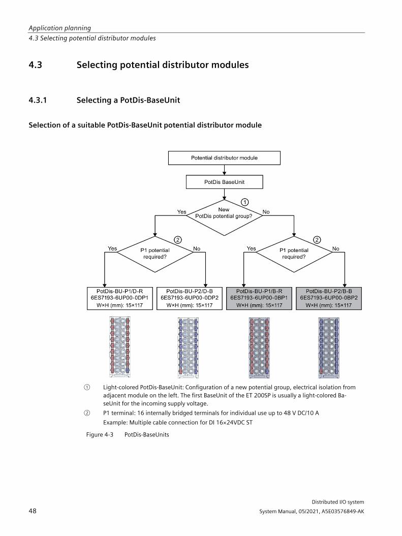
Application planning 4.3 Selecting potential distributor modules
Distributed I/O system
48 System Manual, 05/2021, A5E03576849-AK
4.3 Selecting potential distributor modules
4.3.1 Selecting a PotDis-BaseUnit
Selection of a suitable PotDis-BaseUnit potential distributor module
① Light-colored PotDis-BaseUnit: Configuration of a new potential group, electrical isolation from
adjacent module on the left. The first BaseUnit of the ET 200SP is usually a light-colored Ba-seUnit for the incoming supply voltage.
② P1 terminal: 16 internally bridged terminals for individual use up to 48 V DC/10 A Example: Multiple cable connection for DI 16×24VDC ST
Figure 4-3 PotDis-BaseUnits

Application planning 4.3 Selecting potential distributor modules
Distributed I/O system
System Manual, 05/2021, A5E03576849-AK 49
Please note:
• The potential groups opened with a light-colored PotDis-BU must not contain any I/O modules. You can integrate any dark-colored PotDis-BUs into I/O module potential groups provided they are based on an SELV/PELV supply.
• If you do not need the additional terminals of the PotDis-TB in a potential distributor module, replace the PotDis-TB with a BU cover. You may only connect one potential group within a combination of PotDis-BU and PotDis-TB.
• Only SELV/PELV potentials are permitted on PotDis-BUs. Separate different SELV/PELV potential groups using light-colored PotDis-BUs.
• With potential distributor modules, you may only connect to the PotDis-TB versions BR-W and n.c.-G potential, which exceed the voltage level of SELV/PELV.
• PotDis terminals are not directly configurable as PotDis via GSD/GSDML. When configuring with GSD, always use an dummy module; with GSDML, integrate a free space.
Additional information Additional information on the potential distributor modules (PotDis-BaseUnits and PotDis-TerminalBlocks) is available in the BaseUnits (https://support.industry.siemens.com/cs/ww/de/view/59753521/en) manual.
Application planning 4.3 Selecting potential distributor modules
Distributed I/O system
50 System Manual, 05/2021, A5E03576849-AK
4.3.2 Selecting a PotDis-TerminalBlock
Selection of a suitable PotDis-TerminalBlock With a PotDis-TerminalBlock you are expanding a PotDis-BaseUnit potential distributor module by an additional 18 potential terminals.
You can freely combine PotDis-TerminalBlocks and PotDis-BaseUnits.
The following PotDis-TerminalBlocks are available:
Table 4- 3 Selection of TerminalBlock PotDis-TB
PotDis-TerminalBlocks TerminalBlock Explanation Application
PotDis-TB-P1-R Terminal block with 18 terminals with red spring releases with connection to the supply voltage P1 of the PotDis-BaseUnit with SELV/PELV.
Provision of 18 x P1 potential, e.g. for P1 sensor supply with 3-wire connection for 16-channel digi-tal input modules
PotDis-TB-P2-B Terminal block with 18 terminals with blue spring releases with connection to ground (P2) of the PotDis-BaseUnit
Provision of 18 x P2 potential, e.g. for ground of the sensor supply with 2-wire connection for 16-channel digital output modules
PotDis-TB-n.c.-G Terminal block with 18 terminals with gray spring releases without connection to each other or to a voltage bus of the PotDis-BaseUnit
Provision of 18 x n.c. (not connected), for reserving ("parking") unused signals/lines, e.g. for antivalent sensors in the same potential group
PotDis-TB-BR-W Terminal block with 18 terminals connected to each other with white spring releases without con-nection to a voltage bus of the PotDis-BaseUnit
Provision of 17 terminals with shared potential (the 18th terminal is used for infeed) for supply of ex-ternal consumers
Additional information Additional information on the potential distributor modules (PotDis-BaseUnits and PotDis-TerminalBlocks) is available in the BaseUnits (https://support.industry.siemens.com/cs/ww/de/view/59753521/en) manual.

Application planning 4.4 Hardware configuration
Distributed I/O system
System Manual, 05/2021, A5E03576849-AK 51
4.4 Hardware configuration
Maximum mechanical configuration As soon as one of the following rules applies, the maximum configuration of the ET 200SP has been reached:
Table 4- 4 Maximum mechanical configuration
Properties Rule Number of modules Maximum of 12/30/32/64 I/O modules (depending on the CPU used/the
interface module used; see CPU (https://support.automation.siemens.com/WW/view/en/90466439/133300) and interface module (https://support.automation.siemens.com/WW/view/en/55683316/133300) manuals) For every 6 F-modules F-RQ 1x24VDC/24..230VAC/5A (6ES7136-6RA00-0BF0), the maximum configuration is reduced by 1 module.
Number of motor starters Maximum of 31 motor starters Backplane bus length of the ET 200SP
maximum 1 m mounting width (without CPU/interface module, includ-ing server module)
Electrical maximum configuration for I/O modules The number of operable I/O modules of a potential group is limited by the following factors:
• Power consumption of the I/O modules
• Power consumption of the components supplied via these I/O modules
The maximum current carrying capacity of the terminals on the BaseUnit L+/M is 10 A. Current carrying capacity refers to the current load via the power bus and the infeed bus of the ET 200SP station. Consider the current carrying capacity when using a motor starter.
Maximum electrical configuration for motor starter power bus (24 V DC) To determine the current requirement of an individual motor starter via the power bus, take account of the following parameters:
• Current consumption via DC infeed in the ON state
• Current consumption via DC infeed when switching on (40 ms peak load)
• Increased power consumption through fan operation
• Current requirement via encoder supply of the connected DI module
The maximum current carrying capacity of the 24 V potential group is 7 A across the entire permissible temperature range.

Application planning 4.4 Hardware configuration
Distributed I/O system
52 System Manual, 05/2021, A5E03576849-AK
Maximum electrical configuration for motor starter infeed bus (500 V AC) To determine the current requirement of an individual motor starter via the infeed bus, proceed as follows:
Calculate the current requirement via the main current paths of the individual motor starter. In doing so, take into account the parameter Ie (set rated operational current of the motor starter). The permissible overload characteristics of the motor feeder for motors are determined with the thermal motor model. You calculate the current value (Iinfeed bus) for the infeed bus of the ET 200SP system according to the following formula:
Iinfeed bus = ∑n(Ie * 1.125) n = number of motor starters of a potential group on the infeed bus
Refer to the Manual (https://support.industry.siemens.com/cs/ww/en/view/109479973) for details of how to assign the basic rated operational current Ie parameter.
The following values apply for the potential group of the AC infeed:
• The maximum current carrying capacity is 32 A at an ambient temperature of up to 50 °C.
• The maximum current carrying capacity is 27 A at an ambient temperature of up to 60 °C.
• The maximum current carrying capacity for applications according to UL requirements is 24 A at an ambient temperature of up to 60 °C.
Address space The address space depends on the CPU/interface module (see CPU (https://support.automation.siemens.com/WW/view/en/90466439/133300) Manual) and the interface module used (see Interface module (https://support.automation.siemens.com/WW/view/en/55683316/133300) Manual):
• For PROFINET IO: Dependent on the IO controller/IO device used
• For PROFIBUS DP: Dependent on the DP master used

Application planning 4.5 Forming potential groups
Distributed I/O system
System Manual, 05/2021, A5E03576849-AK 53
4.5 Forming potential groups
4.5.1 Basics
Introduction Potential groups for the ET 200SP distributed I/O system are formed by systematically arranging the BaseUnits.
Requirements For formation of potential groups, the ET 200SP distinguishes between the following BaseUnits:
• BaseUnits BU...D (recognizable by the light-colored terminal box and the light-colored mounting rail release button):
– Opening of a new potential group (power busbar and AUX bus are interrupted to the left)
– Feeding in the supply voltages (DC or AC) up to an infeed current of 10 A, depending on the BaseUnit used.
• BaseUnits BU...B (recognizable by the dark-colored terminal box and the dark-colored mounting rail release button):
– Conduction of the potential group (power busbar and AUX bus continued)
– Tapping the supply voltages (DC or AC) for external components or looping through with a maximum total current of 10 A, depending on the BaseUnit used.
• BaseUnits BU30-MSx (BaseUnit for the motor starter only)
Depending on the version, the BaseUnits in the "BU30-MSx" model series possess the following properties:
– Opening a new potential group or continuing an existing one
– Feeding in the supply voltage L+ up to an infeed current of 7 A DC
– Opening a new load group or continuing an existing one by means of 500 V AC infeed bus
– Feeding in the line voltage up to an infeed current of 32 A AC
– Feeding in and routing the F-DI signal
Note
The BaseUnits BU...B of type B1 and D0 loop through the voltage buses P1/P2 and the AUX bus. The buses are not tapped by the module.

Application planning 4.5 Forming potential groups
Distributed I/O system
54 System Manual, 05/2021, A5E03576849-AK
Placement and grouping of I/O modules Each BaseUnit BU...D that you install in the ET 200SP configuration opens a new potential group and supplies all subsequent I/O modules (on BaseUnits BU...B) with the necessary supply voltage. The first 24 V DC I/O module to the right of the CPU/interface module must be installed on a light-colored BaseUnit BU...D. Exception: If you insert an AC I/O module or an AI Energy Meter as the first I/O module, the first BaseUnit in the ET 200SP configuration can be a dark-colored BaseUnit. The requirement is that you use a CPU or IM 155-6 (as of V3.0).
If you want to place another BaseUnit BU...B after a BaseUnit BU...D, disconnect the power and AUX buses and open a new potential group at the same time. This allows individual grouping of the supply voltages.
Note
All BaseUnits placed in a load group must match the infeed potential of the corresponding light-colored BaseUnits.
Do not connect any BaseUnit of the "BU...B" type on the right of a motor starter's BaseUnit (BU30-MSxx).
Placing and connecting potential distributor modules Potential distributor modules provide potential distributors integrated into the system that you can use to configure a rapid, space-saving customized replacement for standard potential distribution systems.
You can place potential distributor modules at any location within the ET 200SP distributed I/O system. To do so, you must observe the same design rules as for placing and connecting I/O modules. Potential distributor modules are only suitable for SELV/PELV.
A potential distributor module consists of a potential distributor BaseUnit (PotDis-BU) and (if necessary) a potential distributor TerminalBlock (PotDis-TB) plugged onto it. If you do not need the additional terminals of the PotDis-TB, install a BU cover (15 mm) on the PotDis-BaseUnit.
You must not place a BaseUnit for I/O modules in a PotDis potential group formed with a light-colored PotDis-BaseUnit.
Note Identical voltages with potential distributor modules
You can only connect identical (supplied) SELV/PELV voltages to the terminals of a potential distributor module or PotDis potential group. Example: You only connect 24 V DC.
Application planning 4.5 Forming potential groups
Distributed I/O system
System Manual, 05/2021, A5E03576849-AK 55
Placement and grouping of I/O modules and motor starters For the potential group (L+/M), the following slot rules apply within the motor starter modules and other I/O modules of the ET 200SP:
• An unassembled BaseUnit (BaseUnit with BU cover) must be inserted between the CPU, an interface module or an I/O module and the motor starter. This is not necessary between the motor starters.
• The empty slot can take on the potential (24 V DC) of the potential group on the left of it (L+, M), i.e. I/O modules and motor starters can be operated in the same potential group.
• If you would like to insert an I/O module on the right of a motor starter, then use only one BaseUnit of the BU...D Typ A0 type (light terminal box).
• The BaseUnits BU30-MS2, BU30-MS4, BU30-MS5, BU30-MS6, BU30-MS7, BU30-MS8, BU30-MS9 and BU30-MS10 can continue the potential group of other BaseUnit types. However, note the following exceptions:
– Only a BaseUnit of type BU30-MS1 or BU30-MS3 may follow an AS-i module (AS-i potential group).
– Only BaseUnits with fail-safe motor starters can be connected together in the same potential group of an F-PM-E.
WARNING
Hazardous Voltage Can Cause Death, Serious Injury, or Property Damage.
Hazardous electrical voltage can cause electric shock, burns and property damage.
Disconnect your system and devices from the power supply before starting any assembly tasks.

Application planning 4.5 Forming potential groups
Distributed I/O system
56 System Manual, 05/2021, A5E03576849-AK
AUX bus (AUX(iliary) bus) BaseUnits with additional AUX terminals (e.g. BU15-P16+A10+2D) enable the additional connection of a potential (up to the maximum supply voltage of the module), which is applied via the AUX bus.
In the case of light-colored BaseUnits, the AUX bus is interrupted to the left. In the case of BaseUnits BU30-MS1 to BU30-MS7 and BU30-MS10 , the AUX bus is interrupted to the left. The AUX bus of BU30-MS8 and BU30-MS9 is used for F-DI routing.
The AUX bus can be used individually:
• As a PE bar, in which case you may plug a maximum of 8 BaseUnits in the corresponding potential group
• For additionally required voltage
NOTICE
AUX bus as PE bar
If you use an AUX bus as a protective conductor bar, attach the yellow-green color identification labels to the AUX terminals, and establish a functional connection to the central protective conductor connection.
If you stop using the AUX bus as a protective conductor bar, make sure you remove the yellow-green color identification labels and remove the connection to the central protective conductor connection again.
If you use the AUX bus as a protective conductor bar, the corresponding protective conductor tests must be conducted by the installer of the system before commissioning. In addition, both ends of the ET 200SP system assembly must be mechanically fixed to the mounting rail in this case (e.g using 8WA1010-1PH01 ground terminals); this connection can only be detached by using a tool.
The AUX bus is designed as follows:
• Maximum current carrying capacity (at 60 °C ambient air temperature): 10 A
• Permissible voltage: Depending on the BaseUnit type (see BaseUnit manual (https://support.automation.siemens.com/WW/view/en/59753521))
Note
The AUX potential must always be identical to the potential group of the supply voltage if it is not being used as PE.

Application planning 4.5 Forming potential groups
Distributed I/O system
System Manual, 05/2021, A5E03576849-AK 57
Self-assembling voltage buses You must feed in the supply voltage L+ via the BaseUnit BU...D, BU30-MS1 or BU30-MS3 .
Each BaseUnit BU...B allows access to the supply voltage L+ via terminals (red/blue). The motor starter BaseUnits "BU30-MS1", "BU30-MS2", "BU30-MS3", "BU30-MS4", "BU30-MS5", "BU30-MS6", "BU30-MS7", "BU30-MS8", "BU30-MS9" and "BU30-MS10" do not have this access.
Operating principle
1 CPU/interface module 14 Server module 2 BaseUnit BU...D 15 Self-assembling voltage buses P1/P2 3 BaseUnit BU...B 16 AUX bus 4 Potential group 1 17 Infeed bus 500 V AC (L1, L2(N), L3, PE) 5 Potential group 2 18 Supply voltage L+ 6 Potential group 3 19 Supply voltage L+ (3) 7 BaseUnit BU...B with dummy module 20 Additionally required voltage 8 BaseUnit BU30-MS2 21 Supply voltage L+ (2) 9 BaseUnit BU30-MS4 22 Protective conductor (green/yellow) 10 BaseUnit BU30-MS1 23 Supply voltage L+ (1) 11 Potential group 4 24 Supply voltage 1L+ 12 BaseUnit BU30-MS4 13 Backplane bus
Figure 4-4 Placing the BaseUnits

Application planning 4.5 Forming potential groups
Distributed I/O system
58 System Manual, 05/2021, A5E03576849-AK
Connecting different potentials to the power or AUX bus
Note
If you apply different potentials to the power or AUX bus within an ET 200SP station, you need to separate the potential groups with a BaseUnit BU...D.
4.5.2 Forming potential groups with BaseUnit type B1
Introduction The AC I/O modules of the ET 200SP are required to connect sensors/actuators with alternating voltage 24 to 230 V AC.
Requirements BaseUnits BU20-P12+A0+4B (BU type B1) and
• DI 4x120..230VAC ST digital input module
• DQ 4x24..230VAC/2A ST digital output module

Application planning 4.5 Forming potential groups
Distributed I/O system
System Manual, 05/2021, A5E03576849-AK 59
Operating principle Connect the needed module-dependent alternating voltage for the AC I/O modules directly to the BaseUnits BU20-P12+A0+4B (terminals 1L, 2L/1N, 2N). Insert the AC I/O modules on the BaseUnits.
Note Placing the BaseUnits for AC I/O modules
If you insert an AC I/O module as the first I/O module, then a BaseUnit BU20-P12+A0+4B can also be the first BaseUnit to the right of the CPU/interface module in the ET 200SP configuration.
The requirement is that you use a CPU as of V3.0 or IM 155-6 (as of V3.0). • The BaseUnits BU20-P12+A0+4B do not monitor the connected alternating voltage. Please
note the information on limiting the overvoltage and power rating in the AC I/O module manuals.
• Pay attention to the type of the BaseUnits during configuration.
① CPU/interface module ② 24 V DC potential group ③ BaseUnits with DC I/O modules ④ BaseUnits BU 20-P12+A0+4B with AC I/O modules ⑤ Direct voltage ⑥ Alternating voltage
Figure 4-5 Placing the BaseUnits for the AC I/O modules

Application planning 4.5 Forming potential groups
Distributed I/O system
60 System Manual, 05/2021, A5E03576849-AK
4.5.3 Forming potential groups with fail-safe modules
Introduction ET 200SP distributed I/O systems can be configured using fail-safe and non-fail-safe modules. This chapter provides an example of a mixed configuration comprising fail-safe and non-fail-safe modules.
Example of an ET 200SP configuration with fail-safe and non-fail-safe modules In principle, it is not necessary to operate fail-safe and non-fail-safe modules in separate potential groups. You can divide the modules into fail-safe and non-fail-safe potential groups and install them.
The figure below shows an example of a configuration with fail-safe and non-fail-safe modules within a single ET 200SP distributed I/O system.
① IM 155-6 PN HF interface module ② F-module ③ Non-fail-safe module ④ Power module F-PM-E 24VDC/8A PPM ST ⑤ Mixed fail-safe and non-fail-safe potential group with BaseUnits BU15..D and BU15..B.
You achieve SIL3/Cat. 4/PLe for the fail-safe modules. No safety category can be achieved with the non-fail-safe motor starter.
⑥ Non-fail-safe potential group with BaseUnits BU15..D and BU15..B ⑦ Fail-safe potential group with BaseUnits BU20..D, BU15..B and BU30-MSx.
Up to SIL2/Cat. 3/PLd is possible if you disconnect the self-assembling voltage bus and thus the non-failsafe modules.
⑧ Server module ⑨ Self-assembling voltage buses P1/P2 ⑩ Fail-safe motor starter F-DS HF
Figure 4-6 ET 200SP - example of a configuration with fail-safe modules

Application planning 4.5 Forming potential groups
Distributed I/O system
System Manual, 05/2021, A5E03576849-AK 61
4.5.4 Forming potential groups with Ex modules
Ex module group When you form an Ex module group with Ex BaseUnits and Ex power module/Ex I/O modules, observe the information in the System Manual ET 200SP HA Distributed I/O system / ET 200SP Modules for devices used in an explosion hazardous environment (https://support.industry.siemens.com/cs/ww/de/view/109795533/en).
Note Thermal decoupling required
For thermal decoupling of ET 200SP modules and Ex module groups, you must install the following in front of the first Ex power module: • An empty slot with BU cover
or • Recommendation: Potential distributor (PotDis-TerminalBlock PotDis-TB-P1-R on a PotDis-
BaseUnit PotDis-BU-P2/B-B). This allows for a distribution of the supply voltage for the downstream Ex power modules.
4.5.5 Forming potential groups with motor starters
Overview of the functions of the BaseUnits 24 V
infeed 24 V contin-uation from left module
24 V trans-mission
500 V infeed
500 V contin-uation from left module
500 V trans-mission
F-DI infeed
F-DI contin-uation from left module
F-DI routing
3RK1908-0AP00-0AP0 -- -- -- -- -- 3RK1908-0AP00-0CP0 -- -- -- -- -- 3RK1908-0AP00-0BP0 -- -- -- -- -- 3RK1908-0AP00-0DP0 -- -- -- -- -- 3RK1908-0AP00-0EP0 -- -- -- -- 3RK1908-0AP00-0FP0 -- -- -- -- 3RK1908-0AP00-0GP0 -- -- -- 3RK1908-0AP00-0HP0 -- -- -- 3RK1908-0AP00-0JP0 -- -- -- 3RK1908-0AP00-0KP0 -- -- -- Function available
-- Function not available

Application planning 4.5 Forming potential groups
Distributed I/O system
62 System Manual, 05/2021, A5E03576849-AK
Properties of the 500 V AC infeed bus The infeed bus has the following properties:
• The infeed bus is assembled by lining up the motor starter BaseUnits "BU30-MSx".
• The infeed bus distributes the energy to the SIMATIC ET 200SP motor starter within one load group.
• You can open load groups by plugging in a 500 V infeed BaseUnit (BU30-MS1, BU30-MS2, BU30-MS5, BU30-MS7 or BU30-MS8). With BaseUnits BU30-MS3, BU30-MS4, BU30-MS6, BU30-MS9 or BU30-MS10, you can continue the infeed bus from the left BaseUnit.
• Via the infeed bus, you have the option of supplying three-phase load groups via L1, L2 and L3 or with single-phase load groups via L and N.
• The permissible voltage range is between 48 and 500 V AC.
• The maximum current carrying capacity is up 32 A (3-phase) at 50 °C and 500 V. Pay attention to the derating values depending on the configuration.
Properties of the self-assembling voltage bus (L+) Self-assembling voltage buses have the following properties:
• Maximum current: 7 A
• Rated voltage: 24 V
Pay attention to the derating values depending on the configuration.
The AUX1 bus is not supported in the BaseUnits of the SIMATIC ET 200SP motor starters. The AUX1 bus is used in ET 200SP motor starters for routing the F-DI signal in BU30-MS7 to BU30-MS10.
WARNING
Electric shock when operating the infeed bus without touch protection cover
There is a risk of electric shock when touching the infeed bus if you have not fitted a touch protection cover on the infeed bus on the right.
Always fit a touch protection cover on the infeed bus on the right (article number: 3RK1908-1DA00-2BP0).
WARNING
Electric shock when operating a BaseUnit without an inserted motor starter
If you fit a BaseUnit for motor starters without cover (e.g. option handling), there is a risk of an electric shock when touching the BaseUnit.
Always fit a cover on the BaseUnit (article number: 3RK1908-1CA00-0BP0).

Application planning 4.5 Forming potential groups
Distributed I/O system
System Manual, 05/2021, A5E03576849-AK 63
Requirements Use the following devices to form potential groups with motor starters:
• BaseUnits BU30-MSx
• 3RK1308-0xx00-0CP0 motor starters
Operating principle Feed in the supply voltage L+ via the BaseUnit BU30-MS1 and BU30-MS3 at the 24V DC and M terminals.
You can operate the motor starter on a single-phase (L1, N, PE) or a three-phase (L1, L2, L3, PE) AC voltage system. You connect the required AC voltage directly to the BaseUnits BU30-MSx (terminals L1, L2(N), L3, PE). You plug the motor starter onto the BaseUnits.
Note
The motor starters' AC power supply is not connected to the AC power supply for the AC I/O modules (see Chapter "Forming potential groups with BaseUnit type B1 (Page 58)").

Application planning 4.6 Configuration examples for potential groups
Distributed I/O system
64 System Manual, 05/2021, A5E03576849-AK
4.6 Configuration examples for potential groups
4.6.1 Configuration examples with BaseUnits
Table 4- 5 Configuration examples with BaseUnits
BaseUnits Configuration BU15-P16+A0+2D BU15-P16+A0+2B
BU15-P16+A0+2D BU15-P16+A0+2B BU20-P12+A0+0B

Application planning 4.6 Configuration examples for potential groups
Distributed I/O system
System Manual, 05/2021, A5E03576849-AK 65
BaseUnits Configuration
BU15-P16+A10+2D BU15-P16+A10+2B

Application planning 4.6 Configuration examples for potential groups
Distributed I/O system
66 System Manual, 05/2021, A5E03576849-AK
4.6.2 Configuration examples with potential distributor modules
3-wire connection The potential distributor modules allow for a space-saving design. For a 3-wire connection, you can, for example, replace two digital input modules with 8 channels on a 141 mm long BaseUnit with a digital input module with 16 channels and a potential distributor module, each of which is only 117 mm long.
Note
You must not place a BaseUnit for I/O modules in a PotDis potential group formed with a light-colored PotDis-BaseUnit.
The figure below shows a configuration example with a DI 16×24VDC ST digital input module on a BU15-P16+A0+2B BaseUnit and a PotDis-TerminalBlock PotDis-TB-P1-R on a PotDis-BaseUnit PotDis-BU-P2/B-B.
Figure 4-7 Example: 3-wire connection

Application planning 4.6 Configuration examples for potential groups
Distributed I/O system
System Manual, 05/2021, A5E03576849-AK 67
Supply of external components Another application of the potential distributor modules is the supply of potentials for external components. Potential distributor modules enable simple, compact, integrated and clear design.
Observe the current carrying capacity of each terminal: max. 10 A.
Figure 4-8 Example: Supply of external components

Distributed I/O system
System Manual, 05/2021, A5E03576849-AK 68
Installation 5 5.1 Basics
Introduction All modules of the ET 200SP distributed I/O system are open equipment. This means you may only install the ET 200SP distributed I/O system in housings, cabinets or electrical operating rooms and in a dry indoor environment (degree of protection IP20). The housings, cabinets and electrical operating rooms must guarantee protection against electric shock and spread of fire. The requirements regarding mechanical strength must also be met. The housings, cabinets, and electrical operating rooms must not be accessible without a key or tool. Personnel with access must have been trained or authorized.
Installation location Install the ET 200SP distributed I/O system in a suitable enclosure/control cabinet with sufficient mechanical strength and fire protection. Take into account the environmental conditions for operating the devices.
Mounting position You can mount the ET 200SP distributed I/O system in any position. The preferred mounting position is horizontal mounting on a vertical wall.
The ambient temperature may be restricted in certain installation positions. You will find more information in section Mechanical and climatic environmental conditions (Page 288).
Pay attention to chapter "Installation conditions for motor starters (Page 72)" when using motor starters.

Installation 5.1 Basics
Distributed I/O system
System Manual, 05/2021, A5E03576849-AK 69
Mounting rail Mount the ET 200SP distributed I/O system on a mounting rail in accordance with EN 60715 (35 × 7.5 mm or 35 × 15 mm).
You need to ground the mounting rail separately in the control cabinet. Exception: If you install the rail on grounded, zinc-plated mounting plates, there is no need to ground the rail separately.
Note
If the ET 200SP distributed I/O system is exposed to vibration and shock loads, both ends of the ET 200SP system assembly must be mechanically fixed to the mounting rail (e.g using 8WA1010-1PH01 ground terminals). This measure prevents the ET 200SP distributed I/O system from shifting to the side.
Note
If the ET 200SP, distributed IO system is exposed to increased vibrations and shock, fasten the mounting rail to the mounting surface at intervals of approx. 200 mm.
The following are suitable surfaces for the mounting rails:
• Steel strip in accordance with Appendix A of EN 60715 or
• Tinned steel strip. We recommend these in conjunction with the mounting rails in the section Accessories/spare parts (Page 297).
Note
If you use mounting rails from other manufacturers, make sure that they have the required properties for your ambient climatic conditions.

Installation 5.1 Basics
Distributed I/O system
70 System Manual, 05/2021, A5E03576849-AK
Minimum clearances The figure below shows the minimum clearances you must observe when installing or dismantling the ET 200SP distributed I/O system.
Figure 5-1 Minimum clearances
Note Ex module group
When you are using an Ex module group in your configuration, you must observe other minimum clearances.
Additional information on minimum clearances and installing/removing Ex modules is available in the System Manual ET 200SP HA Distributed I/O system / ET 200SP Modules for devices used in an explosion hazardous environment (https://support.industry.siemens.com/cs/ww/de/view/109795533/en).

Installation 5.1 Basics
Distributed I/O system
System Manual, 05/2021, A5E03576849-AK 71
General rules for installation
WARNING
Hazardous Voltage Can Cause Death, Serious Injury, or Property Damage.
Hazardous electrical voltage can cause electric shock, burns and property damage.
Disconnect your system and devices from the power supply before starting any assembly tasks.
Observe the following rules:
• Installation starts on the left-hand side with the CPU/interface module.
• A light-colored BaseUnit BU..D0, BU30-MS1 or BU30-MS3 with infeed of supply voltage L+ follows the CPU/interface module or is placed at the start of each potential group. If you use a CPU or IM 155-6 (V3.0 or higher), the first BaseUnit in the installation of the ET 200SP may also be a dark-colored BaseUnit of type B1 or D0.
• This is followed by BaseUnits BU..B, BU30-MS2 or BU30-MS4 (with a dark-colored terminal box).
• The matching I/O modules / motor starters can be plugged onto the BaseUnits. You will find matching combinations of BaseUnits and I/O modules / motor starters in Application planning (Page 37).
• The server module completes the configuration of the ET 200SP distributed I/O system.
Note
Mount the ET 200SP distributed I/O system only with disconnected supply voltage.
WARNING
Protection from conductive contamination
Taking into account the environmental conditions, the devices must be protected from conductive contamination. This can be achieved, for example, by installing the devices in a control cabinet with the appropriate degree of protection.

Installation 5.2 Installation conditions for motor starters
Distributed I/O system
72 System Manual, 05/2021, A5E03576849-AK
5.2 Installation conditions for motor starters Observe the following installation conditions when using an ET 200SP motor starter:
• Mounting position
You can fit the motor starter vertically or horizontally. The mounting position refers to the alignment of the mounting rail The maximum permissible ambient temperature range depends on the mounting position:
– Up to 60° C: Horizontal mounting position
– Up to 50° C: Vertical installation position
You also need to consider the current carrying capacity of the ET 200SP components.
In the case of a vertical mounting position, use end retainers "8WA1808" at both ends of the ET 200SP station:
• Mounting rail
Use one of the following mounting rails:
– 35x15 mm DIN rail in accordance with DIN EN 60715
– 35x7.5 mm DIN rail in accordance with DIN EN 60715
– SIMATIC S7 mounting rail
• Current carrying capacity of the ET 200SP station Current carrying capacity refers to the current load via the power bus and the infeed bus of the ET 200SP station.
Depending on the ambient conditions and mounting position, you have to take account of the fan unit or additional mechanical fixings.
Mechanical brackets Use the mechanical brackets in the following situations:
• When using a 15 mm mounting rail with a single motor starter installation, i.e. no motor starter mounted directly next to it in the system
• With a vertical mounting position
• For applications according to shipbuilding standards in all mounting positions with 7.5 mm and 15 mm mounting rails

Installation 5.2 Installation conditions for motor starters
Distributed I/O system
System Manual, 05/2021, A5E03576849-AK 73
Designing interference-free motor starters For interference-free operation of the ET 200SP station in accordance with standard IEC 60947-4-2, use a dummy module before the first motor starter. No dummy module is required to the right of the motor starter. Note the following mounting rules: Use the following dummy module on the standard mounting rail between the previous module and the SIMATIC ET 200SP motor starter: BU cover 15 mm: 6ES7133-6CV15-1AM0 with BaseUnit 6ES7193-6BP00-0BA0 For operation of the ET 200SP station with an unused BaseUnit, a cover must be provided for the open BaseUnit plug contacts (power connector, power bus connector, and backplane bus connector). The cover protects the plug contacts against dirt. The BU cover can be ordered as an accessory.
Mount the dummy module The figure below provides a schematic representation of how to implement measures for improving interference immunity.
① Interface module ⑥ Motor starter ② Digital input module ⑦ Motor starter ③ Digital output module ⑧ Server module ④ Dummy module ⑨ Infeed bus cover ⑤ Motor starter
NOTICE Ensure interference immunity You must not plug any other module into the BaseUnit of the dummy module, otherwise interference immunity is no longer ensured.

Installation 5.3 Mounting the CPU/interface module
Distributed I/O system
74 System Manual, 05/2021, A5E03576849-AK
5.3 Mounting the CPU/interface module
Introduction The CPU/the interface module connects the ET 200SP distributed I/O system to the fieldbus and exchanges the data between the higher-level control system and the I/O modules / motor starters.
Requirement The mounting rail is fitted.
Required tools 3 to 3.5 mm screwdriver (only for mounting and removing the BusAdapter)
Mounting the CPU/interface module Watch the video sequence (https://support.automation.siemens.com/WW/view/en/95886218)
To install a CPU/interface module, follow these steps:
1. Install the CPU/interface module on the mounting rail.
2. Swivel the CPU/interface module towards the back until you hear the mounting rail release button click into place.
Figure 5-2 Mounting the CPU/interface module

Installation 5.3 Mounting the CPU/interface module
Distributed I/O system
System Manual, 05/2021, A5E03576849-AK 75
Dismantling the CPU/interface module The CPU/interface module is wired and BaseUnits are located to its right.
To remove the CPU/interface module, follow these steps:
1. Switch off the supply voltage for the CPU/interface module. Remove the 24 V DC connector from the CPU/interface module.
2. Press the mounting rail release button on the first BaseUnit. At the same time, shift the CPU/interface module parallel to the left until it detaches from the rest of the module group.
Note: The mounting rail release button is located above the CPU/interface module or BaseUnit.
3. While pressing the mounting rail release button on the CPU/interface module, swivel the CPU/interface module off of the mounting rail.
Note
It is not necessary to remove the BusAdapter from the CPU/interface module.

Installation 5.4 Installing the CM DP communication module
Distributed I/O system
76 System Manual, 05/2021, A5E03576849-AK
5.4 Installing the CM DP communication module
Introduction You need the CM DP communication module to use the CPU with a DP master or DP slave.
Requirements • The mounting rail is fitted.
• The CPU is installed.
Installing CM DP To install the CM DP communication module, follow these steps:
1. Install the CM DP to the right of the CPU.
2. Swivel the CM DP towards the back until you hear the mounting rail release button click into place.
3. Slide the CM DP to the left until you hear it click into the CPU.
Figure 5-3 Installing CM DP

Installation 5.5 Mounting BaseUnits for I/O modules
Distributed I/O system
System Manual, 05/2021, A5E03576849-AK 77
Removing a CM DP The CPU and the CM DP are wired and BaseUnits are located to its right.
To remove the CM DP communication module, follow these steps:
1. Switch off the supply voltage on the CPU.
2. Press the mounting rail release button on the first BaseUnit and, at the same time, move the CPU and the CM DP parallel to the left until they detach from the rest of the module group (clearance about 16 mm).
3. Press the mounting rail release button on the CM DP and move it to the right until it detaches from the CPU (clearance about 8 mm).
4. While pressing the mounting rail release button on the CM DP, swivel the CM DP off of the mounting rail.
Note
It is not necessary to remove the bus connector from the CM DP unless you have to replace the CM DP.
5.5 Mounting BaseUnits for I/O modules
Introduction The BaseUnits are used for electromechanical connection between the individual ET 200SP components. They also provide terminals for connecting external sensors, actuators and other devices.
Requirements The mounting rail is fitted.
Required tools 3 to 3.5 mm screwdriver (only for dismantling the terminal box and the encoding element)

Installation 5.5 Mounting BaseUnits for I/O modules
Distributed I/O system
78 System Manual, 05/2021, A5E03576849-AK
Installing a BaseUnit Watch "Install configuration" video sequence (https://support.automation.siemens.com/WW/view/en/95886218)
To install a BaseUnit, follow these steps:
1. Hook the BaseUnit onto the mounting rail.
2. Swivel the BaseUnit backwards until you hear it click into place on the mounting rail.
3. Slide the BaseUnit parallel to the left until you hear it latch onto the preceding CPU/interface module or BaseUnit.
Figure 5-4 Installing a BaseUnit
Removing a BaseUnit
WARNING
Hazardous Voltage
Hazardous electrical voltage can cause electric shock, burns and property damage.
Disconnect your system and devices from the power supply before starting any assembly tasks.
To remove a BaseUnit, follow these steps:
The BaseUnit is wired and there are other BaseUnits to its right and left.
To remove a specific BaseUnit, move the adjacent modules. As soon as you have created a clearance of about 8 mm from the adjacent BaseUnits, you can remove the BaseUnit.
Note
You can replace the terminal box without removing the BaseUnit. Refer to section Replacing the terminal box on the BaseUnit (Page 246).

Installation 5.5 Mounting BaseUnits for I/O modules
Distributed I/O system
System Manual, 05/2021, A5E03576849-AK 79
To remove a BaseUnit, follow these steps:
1. Switch off all supply voltages on the ET 200SP distributed I/O system.
2. Loosen the wiring on the BaseUnit (with a 3 to 3.5 mm screwdriver).
3. Removing (from the right):
Press the mounting rail release on the relevant BaseUnit. Move the BaseUnit parallel to the right and swivel the BaseUnit off of the mounting rail while pressing the mounting rail release.
Removing (from the left):
Press the mounting rail release on the relevant BaseUnit and the BaseUnit located to its right. Move the BaseUnit parallel to the left and swivel the BaseUnit off of the mounting rail while pressing the mounting rail release.
Note: The mounting rail release is located above the BaseUnit
Figure 5-5 Removing the BaseUnit (removing from the right)

Installation 5.6 Mounting and dismantling BaseUnits for motor starters
Distributed I/O system
80 System Manual, 05/2021, A5E03576849-AK
5.6 Mounting and dismantling BaseUnits for motor starters
Requirements • The mounting rail is fitted.
• When using a 15 mm mounting rail, you must install the additional mechanical mounting (3RK1908-1EA00-1BP0).
Note
Mechanical bracket for BaseUnit
You will find out how to mount the mechanical bracket for the BaseUnit in chapter "Mounting the mechanical bracket for the BaseUnit (Page 86)".
CAUTION
Protection against electrostatic charge
When handling and installing the SIMATIC ET 200SP motor starter, ensure protection against electrostatic charging of the components. Changes to the system configuration and wiring are only permissible after disconnection from the power supply.
Mounting a BaseUnit Proceed as follows to mount a BaseUnit for motor starters:
1. Hook the BaseUnit into the DIN rail from above.
2. Swing the BaseUnit to the rear until the BaseUnit audibly engages.

Installation 5.6 Mounting and dismantling BaseUnits for motor starters
Distributed I/O system
System Manual, 05/2021, A5E03576849-AK 81
3. Slide the individual BaseUnits to the left to the previous BaseUnit until they audibly engage.
Assemble the BaseUnits only on the DIN rail.
Note
The BaseUnits for motor starters can be plugged together with the BaseUnits for I/O modules.
Disassembling the BaseUnit
WARNING
Hazardous Voltage
Hazardous electrical voltage can cause electric shock, burns and property damage.
Disconnect your system and devices from the power supply before starting any assembly tasks.
To disassemble the BaseUnit, proceed as follows:
1. Disconnect the main power supply and the control current supply of the SIMATIC ET 200SP motor starter.
2. Actuate the DIN rail release on the BaseUnit of the motor starter.
3. Move the BaseUnit to the left. As soon as there is a clearance of approximately 8 mm to the neighboring BaseUnits, you can disassemble the BaseUnit of the motor starter.
4. Swing the BaseUnit away from the DIN rail while pressing the DIN rail release.

Installation 5.7 Installing potential distributor modules
Distributed I/O system
82 System Manual, 05/2021, A5E03576849-AK
5.7 Installing potential distributor modules
Introduction You use the potential distributor module to distribute a variety of potentials (P1, P2).
Requirements The mounting rail is installed.
Installing and uninstalling PotDis-BaseUnit You install/uninstall PotDis-BaseUnits as you would the BaseUnits for I/O modules. You can find additional information in section Mounting BaseUnits for I/O modules (Page 77).
Installing and uninstalling PotDis-TerminalBlock
Installing
Plug the PotDis-TerminalBlock in die PotDis-BaseUnit. Proceed exactly as described in Section Inserting I/O modules / motor starters and BU covers (Page 122).
Uninstalling
To remove a PotDis-TerminalBlock, follow these steps:
1. Switch off all supply voltages on the ET 200SP distributed I/O system.
2. Simultaneously press the top and bottom release buttons of the PotDis-TerminalBlock.
3. Remove the PotDis-TerminalBlock from the front of the PotDis-BaseUnit.

Installation 5.8 Installing the server module
Distributed I/O system
System Manual, 05/2021, A5E03576849-AK 83
5.8 Installing the server module
Introduction The server module on the far right of the assembly/line completes the ET 200SP distributed I/O system.
Requirement The last BaseUnit is mounted.
Installing the server module Watch "Install configuration" video sequence (https://support.automation.siemens.com/WW/view/en/95886218)
Proceed as follows to install a server module:
1. Hook the server module onto the mounting rail to the right of the last BaseUnit.
2. Swivel the server module backwards on the mounting rail.
3. Move the server module parallel to the left until you hear it latch onto the last BaseUnit that precedes it.
Figure 5-6 Installing the server module
Removing the server module Proceed as follows to remove a server module:
1. Press the mounting rail release button on the server module.
2. Move the server module parallel to the right.
3. While pressing the mounting rail release button, swivel the server module off the mounting rail.

Installation 5.9 Mounting further accessories for motor starters
Distributed I/O system
84 System Manual, 05/2021, A5E03576849-AK
5.9 Mounting further accessories for motor starters
5.9.1 Mounting the cover for the 500 V AC infeed bus
Introduction The 500 V infeed bus connects all SIMATIC ET 200SP motor starters. For finger-safe termination of the infeed bus, you must use the cover.
DANGER
Hazardous Voltage Can Cause Death, Serious Injury, or Property Damage.
Hazardous electrical voltage causes electric shock, burns and property damage.
Disconnect your system and devices from the power supply before starting any assembly tasks.
DANGER
Infeed bus - electric shock
You must provide the infeed bus with a touch protection cover on the right (Article No.: 3RK1308-1DA00-2BP0).
Failure to do so will result in the danger of electric shock.
WARNING
Personal injury may occur
On the last plugged-in BaseUnit of a motor starter, place a cover on the opening of the contacts of the infeed bus.

Installation 5.9 Mounting further accessories for motor starters
Distributed I/O system
System Manual, 05/2021, A5E03576849-AK 85
Procedure Proceed as follows to mount the infeed bus cover on a SIMATIC ET 200SP motor starter:
1. Press the cover onto the opening of the BaseUnit on the right until it audibly engages.
The cover can be removed again using 2 fingers and without tools.

Installation 5.9 Mounting further accessories for motor starters
Distributed I/O system
86 System Manual, 05/2021, A5E03576849-AK
5.9.2 Mounting the mechanical bracket for the BaseUnit
Introduction To achieve higher stability, you can use a mechanical bracket on 7.5 mm and 15 mm mounting rails.
You must use the mechanical bracket in the following situations:
• When using a 15 mm mounting rail
• With a vertical mounting position
• For applications according to shipbuilding standards in all mounting positions with 7.5 mm and 15 mm mounting rails
You can find further information on the mechanical bracket in chapter "Installation conditions for motor starters (Page 72)".

Installation 5.9 Mounting further accessories for motor starters
Distributed I/O system
System Manual, 05/2021, A5E03576849-AK 87
Procedure To mount the mechanical bracket, proceed as follows:
1. Insert the mechanical bracket into the opening at the bottom of the BaseUnit.
You use the same mechanical bracket for both mounting rails, rotated through 180° respectively.
2. Hook the BaseUnit into the mounting rail.
3. Insert the mechanical bracket into the BaseUnit.
4. Screw the mechanical bracket securely onto the mounting panel. Use an M4 screw and a suitable washer.

Installation 5.9 Mounting further accessories for motor starters
Distributed I/O system
88 System Manual, 05/2021, A5E03576849-AK
The figures below show the mechanical bracket after installation on a 7.5 mm or 15 mm mounting rail.

Installation 5.9 Mounting further accessories for motor starters
Distributed I/O system
System Manual, 05/2021, A5E03576849-AK 89
5.9.3 Mounting the BU cover
Introduction BU covers are plugged onto BaseUnits whose slots have been reserved for future expansion (as empty slots). The BU covers for motor starters serve as touch protection covers for unoccupied slots.
DANGER
Hazardous Voltage Can Cause Death, Serious Injury, or Property Damage.
Hazardous electrical voltage causes electric shock, burns and property damage.
Disconnect your system and devices from the power supply before starting any assembly tasks.
DANGER
BaseUnit without motor starter - electric shock
If you install a BaseUnit without motor starter in the ET 200SP system (e.g. options handling), you must provide the BaseUnit with a BU cover (Article No: 3RK1908-1CA00-0BP0).
Failure to do so will result in the danger of electric shock.
Procedure To mount the BU cover onto a SIMATIC ET 200SP motor starter, insert the BU cover in the BaseUnit in parallel until both interlocks audibly engage.

Distributed I/O system
System Manual, 05/2021, A5E03576849-AK 90
Wiring 6 6.1 Rules and regulations for operation
Introduction When installing the ET 200SP distributed I/O system as part of a plant or system, special rules and regulations need to be adhered to depending on the area of application.
This section provides an overview of the most important rules that must be observed for the integration of the ET 200SP distributed I/O system in a plant or system.
Specific application Adhere to the safety and accident prevention regulations applying to specific applications, for example machine protection guidelines.
EMERGENCY STOP devices EMERGENCY STOP devices in accordance with IEC 60204 (corresponds to DIN VDE 0113) must remain effective in all operating modes of the plant or system.
External fuses/switches Install the external fuses/switches in the proximity of the ET 200SP distributed I/O system.
Excluding hazardous plant states Hazardous operating states must not occur when
• the plant restarts after a voltage dip or power failure.
• Bus communication is reestablished following a fault.
If necessary, EMERGENCY STOP must be forced!
An uncontrolled or undefined startup must not occur after the EMERGENCY STOP is unlocked.

Wiring 6.1 Rules and regulations for operation
Distributed I/O system
System Manual, 05/2021, A5E03576849-AK 91
Line voltage Below, everything you need to consider in terms of line voltage is described (refer to section Insulation, protection class, degree of protection and rated voltage (Page 292)):
• For fixed plants or systems without an all-pole mains disconnection switch, a mains disconnection device (all-pole) must be available in the building installation.
• For load power supplies, the configured rated voltage range must correspond to the local line voltage.
• For all power circuits of the ET 200SP distributed I/O system, the fluctuation/deviation of the line voltage from the rated value must be within the permitted tolerance.
24 V DC supply Below you will find a description of what you need to pay attention to with 24 V DC supply:
• In the event of danger through overload, you must provide lightning protection measures:
– For external lightning protection
– For internal lightning protection: Only if greater values (phase - ground) or (phase - phase) are required for the power surge than those specified in the section Electromagnetic compatibility (Page 292).
• For 24 V DC supply: Ensure protection by electrical separation and separate cable routing or increased insulation of circuits with dangerous potentials from extra low voltage (SELV/PELV) in accordance with IEC 61131-2 / IEC 61010-2-201.
Requirements for power supplies in the event of voltage interruption
Note
To ensure adherence to IEC 61131-2, only use power packs/power supply units (e.g. 230/400 V AC → 24 V DC) with a mains buffering time of at least 10 ms. Observe the relevant requirements in your application (e.g. product standard for "burners" 30 ms according to EN 298 or 20 ms according to NAMUR recommendation NE 21) with respect to possible voltage interruptions. The latest up-to-date information on PS components is available on the Internet (https://mall.industry.siemens.com).
Of course, these requirements also apply to power packs/power supply units not constructed using ET 200SP or S7-1500/S7-300-/S7-400 design.

Wiring 6.1 Rules and regulations for operation
Distributed I/O system
92 System Manual, 05/2021, A5E03576849-AK
Protection against outside electrical influences Below is a description of what you must pay attention to in terms of protection against electrical impacts and/or faults:
• Make sure that the system for discharging electromagnetic interference is connected to a functional earth or to protective conductor with a sufficient cross-section for all plants with an ET 200SP distributed I/O system.
• For supply, signal and bus lines, you must ensure that the laying of the lines and the installation is correct.
• For signal and bus lines, you must ensure that a wire/cable break or a cross-circuit does not lead to undefined states of the plant or system.
Reference You can find more information in the Designing interference-free controllers (https://support.automation.siemens.com/WW/view/en/59193566) function manual.

Wiring 6.2 Additional rules and regulations for the operation of the ET 200SP with fail-safe modules
Distributed I/O system
System Manual, 05/2021, A5E03576849-AK 93
6.2 Additional rules and regulations for the operation of the ET 200SP with fail-safe modules
6.2.1 Safety extra-low voltage (SELV, PELV) for failsafe modules and failsafe motor starters
WARNING
The failsafe modules must be operated with safety extra-low voltage (SELV, PELV).
You can find more information on safety extra-low voltage (SELV, PELV) in the data sheets of the applicable power supplies, for example.
The fail-safe modules operate with the 24 V DC rated voltage. The tolerance range is 19.2 V DC to 28.8 V DC.
The fail-safe motor starters operate with the 24 V DC rated voltage. The tolerance range is 20.4 V DC to 28.8 V DC.
Within the overvoltage range from 32 V DC to 36 V DC, the F-modules react in a fail-safe manner and the inputs and outputs are passivated. For overvoltages greater than 36 V DC, the F-modules are permanently de-energized.
Use a power supply unit that does not exceed Um = 36 V DC even in the event of a fault. For more on this, refer to the information in the data sheet on overvoltage protection in the case of an internal error. Or implement appropriate measures to limit the voltage, e.g. use of an overvoltage protector.
All system components that can supply electrical energy in any form whatsoever must fulfill this condition.
Each additional circuit (24 V DC) used in the system must have a safety extra-low voltage (SELV, PELV). Refer to the relevant data sheets or contact the manufacturer.
Sensors and actuators with an external power supply can also be connected to F-modules. Make sure that power is supplied to these components from safety extra-low voltage (SELV, PELV) as well. The process signal of a 24 V DC digital module may not exceed a fault voltage Um in the event of a fault.
WARNING
Even when a fault occurs, the permissible potential difference between the supply of the interface module (bus voltage) and the load voltage must not be exceeded.
An external direct electrical connection is one way to meet this requirement. This also prevents potential differences from causing voltage additions at the individual voltage sources, which would cause the fault voltage Um to be exceeded.

Wiring 6.2 Additional rules and regulations for the operation of the ET 200SP with fail-safe modules
Distributed I/O system
94 System Manual, 05/2021, A5E03576849-AK
6.2.2 Requirements for sensors and actuators for fail-safe modules and fail-safe motor starters
General requirements for sensors and actuators Note the following important warning regarding safety-related use of sensors and actuators:
WARNING
Note that instrumentation with sensors and actuators bears a considerable safety responsibility. Also bear in mind that sensors and actuators generally do not have proof-test intervals of 20 years as defined in IEC 61508:2010 without considerable loss of safety.
The probability of hazardous faults and the rate of hazardous faults of safety functions must comply with an SIL-defined high limit. A listing of values achieved by F-modules in the technical specifications of the F-modules is available under "Fail-safe performance characteristics".
To achieve the required safety class, suitably qualified sensors and actuators are necessary.
Additional sensor requirements General rule: To achieve SIL3/Cat. 3/PLe, a single-channel sensor is adequate. However, to achieve SIL3/Cat. 3/PLe with a single-channel sensor, the sensor itself must be SIL3/Cat. 3/PLe-capable; otherwise the sensor must be connected by two channels to achieve this safety level.
To achieve SIL3/Cat. 4/PLe, sensors must be connected by two channels.
WARNING
In the case of fail-safe input modules, the value "0" is output to the F-CPU after detection of faults. You therefore need to make sure that the sensors are implemented in such a way as to ensure the reliable reaction of the safety program when the sensor is in the "0" state.
Example: In its safety program, an EMERGENCY-STOP sensor must achieve the shutdown of the relevant actuator when it is in the "0" state (EMERGENCY-STOP button pressed).

Wiring 6.2 Additional rules and regulations for the operation of the ET 200SP with fail-safe modules
Distributed I/O system
System Manual, 05/2021, A5E03576849-AK 95
Additional requirements for sensors for fail-safe motor starters Only single-channel sensors that fulfill the required safety category themselves may be connected to the fail-safe motor starter's F-DI. Fail-safe laying must be observed in accordance with the required safety category.
WARNING
Safety-related shutdown using the F-DI
Depending on the I/O used, the shutdown takes place via one or two output channels (terminals): • PM-switching: The shutdown takes place via two output channels. • PP-switching: The shutdown takes place via one output channel.
Shutdown via only one output channel (PP-switching) achieves SIL 3 according to EN 62061, PL e / Cat. 4 according to EN ISO 13849-1, if it is ensured that the cabling is installed in a cross-circuit-proof/P-short-circuit-proof manner.
Duration requirements for sensor signals
WARNING
Observe the following requirements for sensor signals: • To ensure the correct detection of the sensor signals via fail-safe modules with inputs,
you need to make sure that the sensor signals are output for a minimum duration. • For pulses to be detected with certainty, the time between two signal changes (pulse
duration) must be greater than the PROFIsafe monitoring time.
Reliable detection by F-modules with inputs
The minimum duration of sensor signals for F-modules with inputs depends on the configured input delay, the parameters of the short circuit test of the sensor supplies, and the configured discrepancy behavior for 1oo2 evaluation. The signal must be greater than the maximum response time of the configured application. Information on calculating the maximum response time can be found in the section "Response times" of the relevant F-module.
The maximum permitted switching frequency of the sensor signals results from the minimum duration.

Wiring 6.2 Additional rules and regulations for the operation of the ET 200SP with fail-safe modules
Distributed I/O system
96 System Manual, 05/2021, A5E03576849-AK
Additional requirements for actuators The fail-safe output modules test the outputs at regular intervals. The F-module briefly switches off the activated outputs and, if necessary, switches on the deactivated outputs. You can assign the maximum duration of the test pulses (dark and light period) with parameters.
Fast reacting actuators may briefly drop out or be activated during the test. If your process does not tolerate this, set the pulse duration of the light or dark test correspondingly or use actuators that have sufficient lag.
WARNING
If the actuators switch voltages greater than 24 V DC (e.g. 230 V AC), the outputs of a fail-safe output module and the parts carrying a higher voltage must be electrically isolated (in accordance with IEC 60664-1).
This is generally the case for relays and contactors. Particular attention must be paid to this with semiconductor switching devices.
Technical specifications of sensors and actuators Refer to the manuals of the fail-safe modules for technical specifications to assist you in selecting sensors and actuators.
6.2.3 Crosstalk of digital input/output signals When fail-safe digital output and input signals are in a single cable, F-DQ modules and F-PM-E modules may experience readback errors.
Cause: capacitive crosstalk
During the bit pattern test of the outputs or the sensor supply of the inputs, the steep switching edge of the output drivers caused by the coupling capacitance of the line may result in crosstalk to other non-activated output or input channels. This may then lead to a response of the readback circuit in these channels. A cross circuit/short-circuit is detected, which leads to safety-related tripping.
Remedy:
• Separate cables for F-DI modules, F-DQ modules, and F-PM-E modules or non-fail-safe DQ modules
• Separate cables for F-DQ channel and F-DI channels for the F-PM-E module
• Coupling relay or diodes in the outputs
• Disable the sensor supply test if safety class requirements allow it.
Cause: magnetic crosstalk
Note that an inductive load connected to the F-DQ channels can induce coupling of a strong magnetic field.
Remedy:
• Separate the inductive loads spatially or shield against the magnetic field.
• Configure the readback time to 50 ms or higher.

Wiring 6.3 Additional rules and regulations for operation of an Ex module group
Distributed I/O system
System Manual, 05/2021, A5E03576849-AK 97
6.3 Additional rules and regulations for operation of an Ex module group
Ex module group You can find the rules and regulations for operation of an Ex module group in the System Manual ET 200SP HA Distributed I/O system / ET 200SP Modules for devices used in an explosion hazardous environment (https://support.industry.siemens.com/cs/ww/de/view/109795533/en)
6.4 Additional rules and instructions for operation with motor starters
6.4.1 Protection against short circuit The motor starter complies with type of coordination 1. Secure the feeder cable for the infeed bus according to current, country-specific rules for conductor protection.
WARNING
Hazardous Voltage at the Motor Can Cause Death, Serious Injury, or Property Damage.
Following a short-circuit, the SIMATIC ET 200SP motor starter is defective. Replace the motor starter following a short-circuit.

Wiring 6.5 Operating the ET 200SP on grounded incoming supply
Distributed I/O system
98 System Manual, 05/2021, A5E03576849-AK
6.5 Operating the ET 200SP on grounded incoming supply
Introduction Below you will find information on the overall configuration of an ET 200SP distributed I/O system on a grounded incoming supply (e.g. TN-S network). The specific subjects discussed are:
• Disconnecting devices and short-circuit and overload protection according to IEC 60364 (corresponds to DIN VDE 0100) and IEC 60204 (corresponds to DIN VDE 0113)
• Load power supplies and load circuits.
Grounded incoming supply In the case of grounded incoming supplies (TN-S system) the neutral conductor (N) and the protective conductor (PE) are each grounded. Both conductors form a part of the overvoltage concept. When a plant is in operation, the current flows across the neutral conductor. When a fault occurs, for example, a single ground fault between a live conductor and ground, the current flows through the protective conductor.
Safe electrical separation (SELV in accordance with IEC 61131-2 or IEC 61010-2-201) Load power supplies/power supply modules with 24 V DC output voltage require safe electrical separation and voltage limiting (extra low voltage). Load power supplies/power supply modules with 24 V DC output voltage are not connected to the protective conductor. According to IEC 61131-2 and IEC 61010-2-201, this protection is referred to as SELV (Safety Extra Low Voltage).
The wiring of SELV circuits must be safely separated from the wiring of other circuits that are not SELV, or the insulation of all conductors must be dimensioned for the higher voltage.
Grounded extra-low voltage (PELV in accordance with IEC 61131-2 or IEC 61010-2-201) Load power supplies/power supply modules with grounded 24 V DC output voltage require safe connection to the protective conductor and voltage limiting (extra low voltage).
According to IEC 61131-2 and IEC 61010-2-201, this protection is referred to as PELV (Protective Extra Low Voltage).
The wiring of PELV circuits must be safely separated from the wiring of other circuits that are not PELV, or the insulation of all conductors must be dimensioned for the higher voltage.

Wiring 6.5 Operating the ET 200SP on grounded incoming supply
Distributed I/O system
System Manual, 05/2021, A5E03576849-AK 99
Configuration of ET 200SP with ungrounded reference potential To conduct interference currents, the reference potential of the CPU/interface module and the BaseUnits BU15...D is connected internally via an RC combination (IM/CPU: R = 10 MΩ / C = 100 nF, BU15...D: R = 10 MΩ / C = 4 nF) with the mounting rail (functional grounding).
• This configuration conducts high-frequency interference currents and prevents static charges.
• It is always possible to configure an ungrounded setup of the ET 200SP distributed I/O system as the ET 200SP distributed I/O system has no fixed ground connection. The power pack/power supply module for 24 V DC must also be ungrounded and electrically isolated.
If you want to configure the ET 200SP distributed I/O system with grounded reference potential, connect the 1M connection of the CPU/interface module electrically with the protective conductor.
Short-circuit / overload protection Various measures as protection against short-circuits and overloads are required for setting up a full installation. The type of components and the binding protective measures depend on which IEC (DIN VDE) regulation applies to your system configuration. The table refers to the figure below and compares the IEC (DIN VDE) regulations.
Table 6- 1 Components and protective measures
Refer to figure IEC 60364 (DIN VDE 0100) IEC 60204 (DIN VDE 0113) Disconnecting device for controller, sensors, and actuators
① Main switch Disconnector
Short-circuit / overload protection: In groups for sensors and actuators
②
③
Single-pole protection of circuits
With grounded secondary circuit: single-pole protec-tion otherwise: all-pole protec-tion
Load current supply for AC load cir-cuits with more than five items of electromagnetic equipment
② Galvanic isolation by trans-former recommended
Galvanic isolation by trans-former recommended
Cable temperature measurement threshold
Note Cable temperature measurement threshold
When choosing a cable, remember that the cable temperature in operation can be up to 30 °C higher than the ambient temperature of the ET200SP system (example: at an ambient temperature of 60 °C, a connection conductor must be dimensioned for a temperature range of at least 90 °C).
You should specify other connection types and material requirements based on the electrical characteristics of the circuits you use and the installation environment.

Wiring 6.5 Operating the ET 200SP on grounded incoming supply
Distributed I/O system
100 System Manual, 05/2021, A5E03576849-AK
ET 200SP in the overall configuration The figure below shows the overall configuration of the ET 200SP distributed I/O system (load current supply and grounding concept) with supply from a TN-S network.
① Main switch ② Short-circuit / overload protection ③ Load current supply ④ Optional for galvanic isolation
Figure 6-1 ET 200SP in the total configuration

Wiring 6.6 Electrical configuration of the ET 200SP
Distributed I/O system
System Manual, 05/2021, A5E03576849-AK 101
Note
In general, you need to connect the DC I/O modules of the ET 200SP distributed I/O system to your own distribution (or batteries) via an upstream, local power supply unit. If you connect the DC I/O modules directly to your own distribution, you need to provide additional protective measures against overvoltages.
6.6 Electrical configuration of the ET 200SP
Electrical isolation
Electrical relationships With the ET 200SP distributed I/O system, there is electrical isolation between:
• The load circuits/process and all other circuit components of the ET 200SP distributed I/O system.
• The communication interfaces of the CPU (PROFINET) or of the interface module (PROFINET/PROFIBUS) and all other circuit components.

Wiring 6.6 Electrical configuration of the ET 200SP
Distributed I/O system
102 System Manual, 05/2021, A5E03576849-AK
The figures below show the electrical relationships of the ET 200SP distributed I/O system with the CPU and the interface module. Only the most important components are represented in the figures.
Figure 6-2 Electrical relationships for ET 200SP with CPU

Wiring 6.6 Electrical configuration of the ET 200SP
Distributed I/O system
System Manual, 05/2021, A5E03576849-AK 103
Figure 6-3 Electrical relationships for ET 200SP with interface module (using IM 155-6 PN ST as an example)

Wiring 6.7 Wiring rules
Distributed I/O system
104 System Manual, 05/2021, A5E03576849-AK
6.7 Wiring rules
Introduction Use suitable cables to connect the ET 200SP distributed I/O system. Also select the cable insulation corresponding to the applied voltage. The tables below set out the wiring rules for CPU/interface module, BaseUnits and motor starter.
Wiring rules for the CPU/interface module and BaseUnits for I/O modules
Wiring rules for ... CPU/interface module (supply voltage)
BaseUnits (push-in terminal)
Permitted cable cross-sections of solid cables (Cu) 0.2 to 2.5 mm2 AWG*: 24 to 13
Permitted cable cross-sections of flexible cables (Cu)
Without end sleeve 0.2 to 2.5 mm2 AWG*: 24 to 13 AWG*: 24 to 14
With end sleeve (with plas-tic sleeve)***
0.25 mm to 1.5 mm2** 0.14 mm to 1.5 mm2 AWG*: 24 to 16 AWG*: 26 to 16
With TWIN end sleeve*** 0.5 mm to 1 mm2 0.5 to 0.75 mm2 (see below) AWG*: 20 to 17 AWG*: 20 to 18
Stripping length of the wires 8 to 10 mm End sleeves in accordance with DIN 46228 with plastic sleeve***
8 and 10 mm long
TWIN end sleeves 12 mm long * AWG: American Wire Gauge
** End sleeves without plastic sleeve: 0.25 to 2.5 mm2/AWG: 24 to 13 *** See note on end sleeves
Note the following for BaseUnits with function version < FS10:
Note End sleeves
Optimum results with respect to a high-quality and permanent electrical connection with maximum conductor pull forces at the same time can be achieved by using crimping dies, preferably with smooth surfaces, which are provided, for example, with rectangular and trapezoidal crimp cross-sections.
Crimping dies with a pronounced wave profile are unsuitable.

Wiring 6.7 Wiring rules
Distributed I/O system
System Manual, 05/2021, A5E03576849-AK 105
TWIN end sleeves for the cables of the I/O modules' push-in terminals Due to the space required by TWIN end sleeves with 0.75 mm2 cross-section, you must ensure a correct angle for the cable arrangement when crimping the TWIN end sleeve so that the cables are optimally arranged.
① Cross-section of the terminal compartment ② Crimping TWIN end sleeves at the correct angle
Figure 6-4 TWIN end sleeves
Wiring rules for motor starters Wiring rules for ... L1(L), L2(N), L3,
PE T1, T2, T3, PE, 24 V DC, F-DI, M
DI1 ... DI3, LC, M, 24 V OUT
Permitted cable cross-sections of solid cables (Cu)
1 to 6 mm2 0.5 to 2.5 mm2 0.2 to 1.5 mm2 AWG: 18 to 10 AWG: 20 to 12 AWG: 24 to 16
Permitted cable cross-sections of flexible cables (Cu)
Without end sleeve
1 to 6 mm2 0.5 to 2.5 mm2 0.2 to 1.5 mm2 AWG: 18 to 10 AWG: 20 to 12 AWG: 24 to 16
With end sleeve 1 to 6 mm2 0.5 to 2.5 mm2 0.25 to 1.5 mm2 AWG: 18 to 10 AWG: 20 to 12 AWG: 24 to 16
With end sleeve (with plastic sleeve)
1 to 4 mm2 0.5 to 1.5 mm2 0.25 to 0.75 mm2 AWG: 18 to 11 AWG: 20 to 16 AWG: 24 to 18
Stripping length of the wires 15 mm 10 mm 8 mm End sleeves according to DIN 46228 with plastic sleeve
15 mm long 10 mm long 8 mm long
Safety standards for fail-safe motor starters Fail-safe motor starters fulfill the following standards under certain conditions:
• PL e/Cat. 4 according to EN ISO 13849-1
• Safety Integrity Level SILCL3 acc. to IEC 62061
To fulfill both standards, lay cross-circuit proof and P-cross-circuit proof control cables from the safe output of a sensor or F-DQ to the safe input of the motor starter, e.g. as a separately sheathed cable or in a separate cable duct.

Wiring 6.7 Wiring rules
Distributed I/O system
106 System Manual, 05/2021, A5E03576849-AK
Line protection The line protection of the SIMATIC ET 200SP motor starter is provided for the motor outgoing feeder cable when the following condition is met:
The cross-section of the motor outgoing feeder cable must be dimensioned for the load ratios of the motor and for the cable-laying method.
Comply with national regulations. The user is responsible for the correct selection and dimensioning of the motor connection cable to DIN VDE 0100 and DIN VDE 0298-4 and/or UL 508.
The conductor protection for the incoming feeders must be ensured by the owner of the installation depending on the cross-section.
Cable temperature measurement threshold
Note Cable temperature measurement threshold
When choosing a cable, remember that the cable temperature in operation can be up to 30 °C higher than the ambient temperature of the ET200SP system (example: at an ambient temperature of 60 °C, a connection conductor must be dimensioned for a temperature range of at least 90 °C).
You should specify other connection types and material requirements based on the electrical characteristics of the circuits you use and the installation environment.

Wiring 6.8 Wiring BaseUnits for I/O modules
Distributed I/O system
System Manual, 05/2021, A5E03576849-AK 107
6.8 Wiring BaseUnits for I/O modules
Introduction The BaseUnits connect the ET 200SP distributed I/O system to the process. The following versions of the BaseUnits can be used:
• BaseUnits (with light-colored terminal box) for opening a potential group: BU..D
• BaseUnits (with dark-colored terminal box) for extending the potential group: BU..B
• BaseUnits with additional AUX terminals or additional terminals: BU..+10..
• BaseUnits with integrated thermal resistor for compensation of the reference junction temperature when connecting thermocouples: BU..T
• PotDis-BaseUnits (with light-colored terminal box) for opening a PotDis potential group: PotDis-BU..D
• PotDis-BaseUnits (with dark-colored terminal box) for extending the potential group: PotDis-BU..B
① Push-in terminal ② Spring release ③ Measuring probe (suitable probes: 1 mm diameter, length ≥ 10 mm while observing the
permitted voltage category) ④ Holder for shield connection Figure 6-5 View of the BaseUnit

Wiring 6.8 Wiring BaseUnits for I/O modules
Distributed I/O system
108 System Manual, 05/2021, A5E03576849-AK
Note
The pin assignment of the BaseUnit depends on the connected I/O module. Information on the BaseUnits and I/O modules can be found in the associated manuals.
Replacement of the terminal box on the BaseUnit is described in the section Replacing the terminal box on the BaseUnit (Page 246).
Note Special terminal designations in the wiring and block diagrams of the I/O modules/BaseUnits • RES: Reserve, these terminals must remain unconnected so that they can be used for
future expansions • n.c.: Not connected, these terminals have no function. However, they can be
connected to potentials specifically defined for a module, for example, for the laying unused wires.
Requirements • The supply voltages are turned off.
• Follow the wiring rules.
• Color identification labels (Page 134) (optional) have been applied.
Required tools 3 to 3.5 mm screwdriver
Tool-free connection of cables: single-wire without wire end ferrule, multi-wire (stranded) with wire end ferrule or ultrasonically sealed
Watch the video sequence (https://support.automation.siemens.com/WW/view/en/95886218)
To connect a wire without tools, follow these steps:
1. Strip 8 to 10 mm of the wires.
2. Only in the case of stranded conductors (except for 2.5 mm² cross-section):
Seal or crimp the wire with wire end ferrules.
3. Insert the wire into the push-in terminal as far as it will go.

Wiring 6.9 Connecting cable shields for I/O modules
Distributed I/O system
System Manual, 05/2021, A5E03576849-AK 109
Connection of cables: multi-wire (stranded), without wire end ferrule, unprocessed To connect a wire without a wire end ferrule, follow these steps:
1. Strip 8 to 10 mm of the wires.
2. Push with the screwdriver into the spring release.
3. Insert the wire into the push-in terminal as far as it will go.
4. Pull the screwdriver out of the spring release.
Removing wires Using the screwdriver, press the spring release of the terminal as far as it will go and pull out the wire.
Note
When you press the spring release, you should not pull on the wire/cable at the same time. This prevents you from damaging the terminal.
6.9 Connecting cable shields for I/O modules
Introduction • You need the shield connector to contact cable shields (e.g. for analog modules). The
shield connector conducts interference currents on cable shields to ground via the mounting rail. It is not necessary to contact the shield at where the cable enters the cabinet.
• Attach the shield connector to the BaseUnit.
• The shield connector consists of a shield contact and a shield terminal.
• The shield connector is automatically connected to the functional ground (FG) of the mounting rail after installation.

Wiring 6.9 Connecting cable shields for I/O modules
Distributed I/O system
110 System Manual, 05/2021, A5E03576849-AK
Requirements • BaseUnit with a width of 15 mm
• The shield terminal is suitable for cables with max. ∅ 7 mm each.
Figure 6-6 Shield terminal
Required tools • Stripping tool
Procedure Watch the "Wiring BaseUnits" video sequence (https://support.automation.siemens.com/WW/view/en/95886218)
To connect the cable shield, follow these steps:
1. If necessary, connect the supply voltage L+ and ground to the BaseUnit.
2. Press the shield contact up into the mount until you hear it click into place.
3. Remove the cable insulation material around the shield terminal.
Connect the cable to the BaseUnit and place the cable in the shield contact.

Wiring 6.9 Connecting cable shields for I/O modules
Distributed I/O system
System Manual, 05/2021, A5E03576849-AK 111
4. Insert the shield terminal into the shield contact.
5. Tighten the shield terminal with approximately 0.5 Nm.
① Mount ⑤ Insulation material removed (approx. 20
mm) ② Supply voltage L+, ground ⑥ Cable to the encoder ③ Shield contact ⑦ Shield terminal ④ Flat connector for push-on contacts
(6.3 × 0.8 mm)
Figure 6-7 Mounting the shield contact

Wiring 6.10 Wiring BaseUnits for motor starters
Distributed I/O system
112 System Manual, 05/2021, A5E03576849-AK
6.10 Wiring BaseUnits for motor starters
Introduction The following versions of BaseUnits can be used:
• BU30-MS1 (with 24 V DC and 500 V AC infeed)
• BU30-MS2 (with 500 V AC infeed)
• BU30-MS3 (with 24 V DC infeed)
• BU30-MS4 (without infeed)
• BU30-MS5 (with 500 V AC infeed and single F-DI)
• BU30-MS6 (without infeed and with single F-DI)
• BU30-MS7 (with F-DI and 500 V AC infeed)
• BU30-MS8 (with 500 V AC infeed and F-DI routing)
• BU30-MS9 (with F-DI routing)
• BU30-MS10 (with F-DI infeed)
The following figure shows an example of a BaseUnit BU30-MS1 (with the maximum number of terminals):
① Push-in terminal ② Spring release
Figure 6-8 Terminals on a BaseUnit BU30-MS1

Wiring 6.10 Wiring BaseUnits for motor starters
Distributed I/O system
System Manual, 05/2021, A5E03576849-AK 113
The following figure shows an example of a BaseUnit BU30-MS5 (with the maximum number of terminals):
① Push-in terminal ② Spring release
Figure 6-9 Terminals on a BaseUnit BU30-MS5
DANGER
Hazardous Voltage Can Cause Death, Serious Injury, or Property Damage.
Hazardous electrical voltage can cause electric shock, burns and property damage.
Turn off and lock out all power supplying this device before working on this device.
For wiring finely-stranded or stranded conductors without end sleeves on push-in connections, a screwdriver is required.

Wiring 6.10 Wiring BaseUnits for motor starters
Distributed I/O system
114 System Manual, 05/2021, A5E03576849-AK
Requirements • The supply voltages are switched off
• Observe the wiring rules
NOTICE
Interconnection of the F-DI input of BaseUnits BU-30-MS5, BU-30-MS6, BU-30-MS7 and BU-30-MS10 with surge filters
If your system requires overvoltage protection, you must interconnect the F-DI input of the BaseUnits BU-30-MS5, BU-30-MS6, BU-30-MS7 and BU-30-MS10 with surge filters.
Please see "Electromagnetic Compatibility" in the technical specifications.
Required tools Use the screwdriver "SZF 1-0.6x3.5" (for finely-stranded cables only).
Connecting conductors: Solid without end sleeve, stranded (stranded wire) with end sleeve To connect a cable, proceed as follows:
1. Insulate the cables in accordance with the table in chapter "Electromagnetic compatibility of fail-safe modules (Page 285)".
2. Only in the case of stranded conductors:
Crimp the cable with end sleeves.
3. Insert the cable into the push-in terminal as far as it will go.
4. Pull on the cable to ensure it is tight.
Connecting conductors: multi-wire (stranded), without end sleeve, unfinished To connect a cable, proceed as follows:
1. Insulate the cables in accordance with the table in chapter "Wiring rules (Page 104)".
2. Press the screwdriver into the spring release.
3. Insert the conductor into the push-in terminal until it engages.
4. Pull the screwdriver out of the spring release.
5. Check whether or not the conductor is firmly connected by pulling on the cable.
Video sequence At the following Internet link, you can see a video about connecting conductors: Wire BaseUnits (http://support.automation.siemens.com/WW/view/en/95886218)

Wiring 6.11 Connecting the 3DI/LC module for the motor starter
Distributed I/O system
System Manual, 05/2021, A5E03576849-AK 115
Releasing conductors To release a conductor, proceed as follows:
1. Press the screwdriver into the spring release of the terminal until it engages.
2. Pull the conductor out.
Note
When pressing the spring release, you must not pull on the wire/cable at the same time. In this way, you avoid damaging the terminal.
6.11 Connecting the 3DI/LC module for the motor starter You will find further information on the 3DI/LC module in the ET 200SP motor starter (https://support.industry.siemens.com/cs/ww/en/view/109479973) manual.
Procedure The figure below shows the connections of the 3DI/LC module.
① Digital input 3 ② Digital input 2 ③ Digital input 1 ④ Local control (manual local) ⑤ Ground ⑥ 24 V DC/ 100 mA output

Wiring 6.11 Connecting the 3DI/LC module for the motor starter
Distributed I/O system
116 System Manual, 05/2021, A5E03576849-AK
Note
The digital inputs (1 to 4) are not isolated. The reference potential is M (5). Control the digital inputs only via a unit supplied from the 24 V DC output (6).
Connect only cables of a width not exceeding 30 m to the 3DI/LC module.
The supply (5 and 6) is protected against short-circuits.
Terminal sketch of the 3DI/LC module The following diagram shows a terminal sketch of the 3DI/LC module:
Figure 6-10 Connection example of inputs

Wiring 6.12 Connecting the supply voltage to the CPU/interface module
Distributed I/O system
System Manual, 05/2021, A5E03576849-AK 117
6.12 Connecting the supply voltage to the CPU/interface module
Introduction The supply voltage of the CPU/interface module is supplied by means of a 4-pin connector plug located on the front of the CPU/interface module.
Power supply unit Only use power supply units of type SELV/PELV with safe electrically isolated functional extra low voltage (≤ 28.8 V DC).
Connection for supply voltage (X80) The connections of the 4-pole connector have the following meaning:
① +24 V DC of the supply voltage (current limited to 10 A) ② Ground of the supply voltage (current limited to 10 A) ③ Ground of the supply voltage for loop-through ④ +24 V DC of the supply voltage for loop-through ⑤ Spring opener (one spring opener per terminal) 1L+ and 2L+ and 1M and 2M are internally jumpered
Figure 6-11 Supply voltage connection
A strain relief is not present. The cable connector offers you the option of looping the supply voltage uninterrupted, even when it is unplugged.
For the maximum wire cross-sections, observe the information in the tables of the wiring rules (Page 104).
Requirements • Only wire up the connector plug when the supply voltage is turned off.
• Follow the wiring rules (Page 104).
Required tools 3 to 3.5 mm screwdriver

Wiring 6.12 Connecting the supply voltage to the CPU/interface module
Distributed I/O system
118 System Manual, 05/2021, A5E03576849-AK
Tool-free connection of cables: single-wire without end sleeve, multi-wire (stranded) with end sleeve or ultrasonically sealed
Watch video sequence: "Connect BusAdapter to the interface module" (https://support.automation.siemens.com/WW/view/en/95886218)
To connect a wire without tools, follow these steps:
1. Strip 8 to 10 mm of the wires.
2. Only in the case of stranded conductors:
Seal or crimp the wire with end sleeves.
3. Insert the cable into the push-in terminal as far as it will go.
4. Push the wired connector plug into the plug socket of the interface module.
Connection of cables: multi-wire (stranded), without end sleeve, unfinished To connect a wire without an end sleeve, follow these steps:
1. Strip 8 to 10 mm of the wires.
2. Using a screwdriver, press the spring release and insert the wire into the push-in terminal as far as it will go.
3. Pull the screwdriver out of the spring release.
4. Push the wired connector plug into the socket in the interface module.
Removing a wire Using the screwdriver, press the spring release as far as it will go and pull out the wire.
Wiring 6.13 Connecting interfaces for communication
Distributed I/O system
System Manual, 05/2021, A5E03576849-AK 119
6.13 Connecting interfaces for communication Connect the communication interfaces of the ET 200SP distributed I/O system using the standardized connector or directly. If you want to prepare communication cables yourself, the interface assignment is specified in the manuals of the corresponding modules. Observe the mounting instructions for the connectors.
Detailed information on the available BusAdapters and the procedure for connecting PROFINET IO to the CPU/interface module is available in the BusAdapter (https://support.industry.siemens.com/cs/ww/en/view/109751716) manual.
6.13.1 Connecting PROFINET IO (port P3) to the CPU
Introduction You use the RJ-45 bus connector to connect PROFINET IO (port P3) directly to the CPU.
Required accessories • Cable ties with standard width of 2.5 mm or 3.6 mm for strain relief
• Please observe the specifications in the PROFINET Installation Guide (https://www.profibus.com).
Mounting the bus connector Mount the PROFINET connector in accordance with the instructions in the PROFINET Installation Guide (https://www.profibus.com).

Wiring 6.13 Connecting interfaces for communication
Distributed I/O system
120 System Manual, 05/2021, A5E03576849-AK
Procedure Insert the RJ45 bus connector into the PROFINET port (port P3) on the CPU.
Note Cable support and strain relief
If you are using a FastConnect RJ45 bus connector with 90° cable outlet (6GK1901-1BB20-2AA0), we recommend you provide strain relief for the PROFINET connecting cable. For this you need a cable tie with a standard width of 2.5 mm or 3.6 mm.
Use it to fasten the PROFINET connecting cable directly after it exits the bus connector to the provided cable support on the CPU (on the front directly below the PROFINET interface X1P3).
① CPU ② PROFINET connecting cable ③ Strain relief (cable tie) ④ Cable support ⑤ FastConnect RJ45 bus connector with 90° cable outlet ⑥ PROFINET connector (port P3)
Figure 6-12 Connecting PROFINET IO (port P3) to the CPU

Wiring 6.13 Connecting interfaces for communication
Distributed I/O system
System Manual, 05/2021, A5E03576849-AK 121
6.13.2 Connecting the PROFIBUS DP interface to the interface module/communications module CM DP
Introduction Using the bus connector (RS485), connect the PROFIBUS DP to the interface module/communications module CM DP.
Required tools 3 to 3.5 mm screwdriver
Procedure To connect the PROFIBUS DP interface to the interface module / DP communication module CM DP, follow these steps:
1. Connect the PROFIBUS cable to the bus connector.
2. Plug the bus connector into the PROFIBUS DP connector.
3. Securely tighten the fixing screws of the bus connector (0.3 Nm).
① Interface module ② PROFIBUS FastConnect bus connector ③ PROFIBUS connecting cable ④ Communications module CM DP Figure 6-13 Connect PROFIBUS DP to the interface module/communications module CM DP

Wiring 6.14 Inserting I/O modules / motor starters and BU covers
Distributed I/O system
122 System Manual, 05/2021, A5E03576849-AK
Reference You can find additional information on the PROFIBUS FastConnect bus connector in the corresponding product information on the Internet (https://support.industry.siemens.com/cs/ww/de/view/109793857/en).
6.14 Inserting I/O modules / motor starters and BU covers
Introduction • You insert the I/O modules on the BaseUnits. The I/O modules are self-coding and type-
coded.
• You insert the PotDis-TerminalBlocks on the PotDis-BaseUnits.
• You insert the BU covers on BaseUnits whose slots are not equipped with I/O modules/PotDis-TerminalBlocks.
• You insert the BU covers on BaseUnits whose slots have been reserved for future expansion (as empty slots).
• The BU covers for motor starters serve as touch protection covers for unoccupied slots.
The BU covers have a holder for the reference identification label on the inside. For future expansion of the ET 200SP, remove the reference identification label from the holder and insert it into the final I/O module. It is not possible to attach a reference identification label to the BU cover itself.
There are three versions:
– BU cover with a width of 15 mm
– BU cover with a width of 20 mm
– BU cover with a width of 30 mm (for motor starters)
Requirement Refer to chapter "Application planning (Page 37)".

Wiring 6.14 Inserting I/O modules / motor starters and BU covers
Distributed I/O system
System Manual, 05/2021, A5E03576849-AK 123
Plugging in I/O modules and BU covers Watch video sequence: "Insert I/O modules" (https://support.automation.siemens.com/WW/view/en/95886218)
Insert the I/O module or BU cover parallel into the BaseUnit until you hear both latches click into place.
Figure 6-14 Plugging in I/O modules or BU covers (using an I/O module as example)

Wiring 6.15 Mounting/disassembly of motor starters
Distributed I/O system
124 System Manual, 05/2021, A5E03576849-AK
6.15 Mounting/disassembly of motor starters
6.15.1 Mounting the fan
Procedure Proceed as follows to mount a fan on a SIMATIC ET 200SP motor starter:
1. Slide the fan onto the motor starter until you can hear the fan engage.
Observe the blowing direction of the fan when mounting. The air stream must be directed to the inside of the motor starter. The correct blowing direction is indicated by arrows on the bottom of the fan.
2. Insert the connection plug into the opening above the fan.
3. Secure the fan cable to the fixing eyes on the right-hand side of the fan cover.
Note Specified ambient temperatures are not reached if the fan is incorrectly installed
If you do not observe the blowing direction of the fan when mounting, the specified ambient temperatures will not be reached. The device shuts down prematurely due to excessively high temperature.

Wiring 6.15 Mounting/disassembly of motor starters
Distributed I/O system
System Manual, 05/2021, A5E03576849-AK 125
6.15.2 Mounting/disassembly of motor starters
Procedure
CAUTION
Protection against electrostatic charge
When handling and installing the SIMATIC ET 200SP motor starter, ensure protection against electrostatic charging of the components. Changes to the system configuration and wiring are only permissible after disconnection from the power supply.
To assemble a SIMATIC ET 200SP motor starter, proceed as follows:
• Position the mechanical interlock of the SIMATIC ET 200SP motor starter in the assembly/disassembly position ②
• Place the SIMATIC ET 200SP motor starter onto the BaseUnit.
• Turn the mechanical interlock clockwise to the parking position ③
• Turn the mechanical interlock counterclockwise to the operating position (= end position) ①
① ② ③

Wiring 6.15 Mounting/disassembly of motor starters
Distributed I/O system
126 System Manual, 05/2021, A5E03576849-AK
① Operating position/READY
The motor starter is firmly locked in the BaseUnit, and all electrical contacts are connected. ② Assembly/disassembly position
All electrical contacts are open, and you can use the SIMATIC ET 200SP motor starter in the BaseUnit, or you can remove it from the BaseUnit.
③ Parking position/OFF In this position, you cannot remove the SIMATIC ET 200SP motor starter from the BaseUnit, but all electrical contacts are open. In addition, you can open the locking lever on the mechanical rotary interlock in this position, and fix the position with a padlock (shackle diameter 3 mm). This ensures the isolating function in accordance with IEC 60947-1. In the parking position, the motor starter counts as a disconnected element for the head module. During operation, the parking position is therefore a hot swapping state. See also Removing and inserting I/O modules/motor starters (hot swapping) (Page 239)
Note Parking position/OFF
This position is only permissible for maintenance purposes and not for continuous operation. In this position, dust protection and mechanical durability are not ensured.
If you do not use the motor starter for an extended period, remove it and attach the BU cover (3RK1908-1CA00-0BP0).
Mount the touch protection cover for the infeed bus on the last BaseUnit.
Note Touch protection cover for the infeed bus
You will find out how to mount the touch protection cover of the infeed bus on a SIMATIC ET 200SP motor starter in chapter "Mounting the cover for the 500 V AC infeed bus (Page 84)".

Wiring 6.15 Mounting/disassembly of motor starters
Distributed I/O system
System Manual, 05/2021, A5E03576849-AK 127
To connect the assembly, mount the server module after the last BaseUnit.
Note Server module
You can find out how to assemble/disassemble the server module in chapter "Installing the server module (Page 83)".
Note Removing the motor starter
You will find out how to remove the motor starter in chapter "Replacing a motor starter (Page 245)".
6.15.3 3DI/LC module
Introduction The optional 3DI/LC module with three inputs and one further LC input can be connected to the motor starter. The status of the inputs of the 3DI/LC module can be seen via the process image input (PII) of the motor starter.
Note
The 3DI/LC module can be used for the motor starter and the fail-safe motor starter.
The input actions can be parameterized. For reasons of operational safety, the LC input is permanently set to manual local mode. For example, by parameterizing the inputs DI1 - DI3 with motor CLOCKWISE or motor COUNTER-CLOCKWISE, you can control the motor in manual local mode.
The figure below shows the 3DI/LC module.

Wiring 6.15 Mounting/disassembly of motor starters
Distributed I/O system
128 System Manual, 05/2021, A5E03576849-AK
Assembly
WARNING
Risk of injury from automatic restart
When you mount the the 3DI/LC module, the motor starter can switch on autonomously if an ON command (DI1 to DI3) is active. This can result in property damage or serious injury caused by connected devices that are automatically started up.
Revoke the ON commands at DI1 to DI3 before mounting the 3DI/LC module.
Proceed as follows to mount a 3DI/LC module onto a motor starter:
1. Wire the 3DI/LC module according to the connection diagram.
Note
Connecting the 3DI/LC module
You will find out how to connect the 3DI/LC module in chapter "Connecting the 3DI/LC module for the motor starter (Page 115)".
2. Slide the 3DI/LC module into the motor starter until the 3DI/LC module engages.

Wiring 6.15 Mounting/disassembly of motor starters
Distributed I/O system
System Manual, 05/2021, A5E03576849-AK 129
The figure below shows a motor starter with a mounted 3DI/LC module.
Disassembly Proceed as follows to remove a 3DI/LC module from a motor starter:
1. Push the release lever on the rear of the 3DI/LC module.
① Release lever
2. Remove the 3DI/LC module from the motor starter while pressing the release lever.

Wiring 6.16 Labeling ET 200SP
Distributed I/O system
130 System Manual, 05/2021, A5E03576849-AK
6.16 Labeling ET 200SP
6.16.1 Factory markings
Introduction For better orientation, the ET 200SP is equipped with various markings ex factory, which help in the configuration and connection of the modules.
Factory markings • Module labeling
• Color coding of module type
– Digital input modules: white
– Digital output modules: black
– Analog input modules: light blue
– Analog output modules: dark blue
– Technology module: turquoise
– Communication module: light gray
– Special module: mint green
• Module information
– Functional version of the module, e.g. "X/2/3/4" (= functional version 1)
– Firmware version of the module at delivery, e.g. "V1.0.0"
– Color code for usable color identification label, e.g. "CC0"
– Usable BaseUnit type, e.g. "BU: A0"

Wiring 6.16 Labeling ET 200SP
Distributed I/O system
System Manual, 05/2021, A5E03576849-AK 131
• Color coding of the potential group
– Opening the potential group: Light-colored terminal box and light-colored mounting rail release button
– Further conduction of the potential group: Dark-colored terminal box and dark-colored mounting rail release button
• Color coding of the spring releases
– Process terminals: gray, white
– AUX terminals: turquoise
– Additional terminals: red, blue
– Terminals for self-assembling voltage buses P1, P2: red, blue
① Function class ② Color coding of module type ③ Function and firmware version ④ Color code for selection of the color coding labels ⑤ BU type ⑥ Color coding of the spring releases (by group) ⑦ Color coding of the potential group ⑧ Article number ⑨ Wiring diagram ⑩ 2D matrix code ⑪ Module type and designation Figure 6-15 Factory markings

Wiring 6.16 Labeling ET 200SP
Distributed I/O system
132 System Manual, 05/2021, A5E03576849-AK
6.16.2 Optional markings
Introduction In addition to the factory markings, there are also other options for labeling and/or marking terminals, BaseUnits and I/O modules for the ET 200SP distributed I/O system.
Optional markings
Color identification labels
The color identification labels are module-specific labels for color coding the potentials of the I/O modules. A color code (e.g. 01) is printed on each color identification label and I/O module. The color code allows you to read which color identification label is required for the terminals of the associated BaseUnit directly from the I/O module.
The following versions of color coded labels are available:
• Module-specific color combinations for the process terminals (see the device manuals I/O modules (https://support.automation.siemens.com/WW/view/en/55679691/133300)). The different colors have the following meaning: Gray = input or output signal, red = potential +, blue = ground.
• For the AUX terminals in the colors yellow-green, blue or red
• For the add-on terminals in the colors blue-red
• For the potential distributor modules (see manual BaseUnits (https://support.automation.siemens.com/WW/view/en/59753521)):
– For PotDis-BaseUnit PotDis-BU-P1/x-R: red For PotDis-BaseUnit PotDis-BU-P2/x-B: blue
– For PotDis-TB-P1-R: red or gray For PotDis-TB-P2-B: blue or gray For PotDis-TB-BR-W: depending on application, yellow/green, blue, red or gray For PotDis-TB-n.c.-G: gray
Reference identification labels
The reference identification labels (in accordance with EN 81346) can be inserted onto each CPU/interface module, BusAdapter, BaseUnit, I/O module and PotDis-TerminalBlock. This makes it possible to create a fixed assignment between the reference identification label of the BaseUnit and the I/O module/PotDis-TerminalBlock.
With the standard plotter setting, the reference identification label is suitable for automatic labeling with E-CAD systems.

Wiring 6.16 Labeling ET 200SP
Distributed I/O system
System Manual, 05/2021, A5E03576849-AK 133
Labeling strips
The labeling strips can be inserted in the CPU/interface module, I/O module and BU cover and allow identification of the ET 200SP distributed I/O system. The labeling strips can be ordered on a roll for thermal transfer printers or as DIN A4 format sheets for laser printers.
① Reference identification labels ② Labeling strips ③ Color identification labels
Figure 6-16 Optional markings

Wiring 6.16 Labeling ET 200SP
Distributed I/O system
134 System Manual, 05/2021, A5E03576849-AK
6.16.3 Applying color identification labels
Requirements The BaseUnits must not be wired when you apply the color identification labels.
Required tools 3 mm screwdriver (only for removing the color identification labels)
Applying color identification labels Press color identification labels into the terminal box of the BaseUnit.
Note
To remove the color identification labels, you must first disconnect the wiring on the BaseUnit and then carefully lever the color identification labels out of the holder using a screwdriver.
① Module-specific color identification labels (15 mm) for the process terminals. You can find addi-
tional information in the I/O Module (https://support.automation.siemens.com/WW/view/en/55679691/133300) manual.
② Color identification labels (15 mm) for the 10 AUX terminals ③ Color identification label (15 mm) for the 10 add-on terminals ④ Color identification labels (20 mm) for the 4 AUX terminals ⑤ Color identification labels (20 mm) for the 2 AUX terminals
Figure 6-17 Applying color identification labels (example)

Wiring 6.16 Labeling ET 200SP
Distributed I/O system
System Manual, 05/2021, A5E03576849-AK 135
NOTICE
AUX bus as PE bar
If you use an AUX bus as a protective conductor (PE), attach the yellow-green color identification labels to the AUX terminals.
If you stop using the AUX terminals as a protective conductor bar, remove the yellow-green color identification labels and make sure that the system is still protected.
NOTICE
Supply of incorrect potential possible
Check that the color-coded labels/wiring is correct before commissioning the plant.
6.16.4 Applying labeling strips
Procedure Watch video sequence: "Labeling" (https://support.automation.siemens.com/WW/view/en/95886218)
Proceed as follows to install a labeling strip:
1. Label the strips.
2. Insert the labeling strip into the interface module or I/O module.

Wiring 6.16 Labeling ET 200SP
Distributed I/O system
136 System Manual, 05/2021, A5E03576849-AK
6.16.5 Applying reference identification labels
Procedure Watch video sequence: "Labeling" (https://support.automation.siemens.com/WW/view/en/95886218)
Proceed as follows to install a reference identification label:
1. Break off the reference identification labels from the sheet.
2. Insert the reference identification labels into the opening on the CPU/interface module, BusAdapter, BaseUnit, I/O module and PotDis-TerminalBlock. The insertion opening is located on top of the BaseUnit or the I/O module/PotDis-TerminalBlock.
Note
Reference identification label
The printable side of the reference identification label must be facing forward.
① Reference identification labels ② Opening for label Figure 6-18 Applying reference identification labels

Distributed I/O system
System Manual, 05/2021, A5E03576849-AK 137
Configuring 7 7.1 Configuring ET 200SP
Introduction The ET 200SP distributed I/O system is configured and assigned parameters with STEP 7 (CPU/interface module, I/O modules, motor starter and server module) or using configuration software of a third-party manufacturer (interface module, I/O modules, motor starter and server module).
"Configuring" is understood to mean the arranging, setup and networking of devices and modules within the device view or network view. STEP 7 graphically represents modules and racks. Just like "real" module racks, the device view allows the insertion of a defined number of modules.
When the modules are inserted, STEP 7 automatically assigns the addresses and a unique hardware identifier (HW identifier). You can change the addresses later. The hardware identifiers cannot be changed.
When the automation system is started, the CPU/interface module compares the configured planned configuration with the system's actual configuration. You can make parameter settings to control the response of the CPU/interface module to errors in the hardware configuration.
"Parameterizing" the components used signifies setting their properties. During parameter assignment, the hardware parameters are set and the settings for data exchange are made:
• Properties of the modules to which parameters can be assigned
• Settings for data exchange between components
STEP 7 compiles the hardware configuration (result of "configuring" and "assigning parameters") and downloads it to the CPU/interface module. The CPU/interface module then connects to the configured components and transfers their configuration and parameters. Modules can be replaced very easily because STEP 7 transfers the configuration and parameters when a new module is inserted.

Configuring 7.1 Configuring ET 200SP
Distributed I/O system
138 System Manual, 05/2021, A5E03576849-AK
Requirements for configuration of the CPU
Table 7- 1 Requirement for installing the CPU
Configuration software Requirements Installation infor-mation
CPU 151xSP-1 PN: STEP 7 (TIA Portal) as of V13 Update 3
• PROFINET IO • PROFIBUS DP (optional): With the
communication module CM DP
STEP 7 online help
CPU 151xSP F-1 PN: STEP 7 (TIA Portal) as of V13 SP1 CPU 151xSP-1PN (as of FW version V1.8), CPU 151xSP F-1 PN (as of FW version V1.8): STEP 7 (TIA Portal) as of V13 SP1 Update 4
Requirements for configuration of the interface module
Table 7- 2 Requirement for installing the interface module
Configuration software Requirements Installation infor-mation
STEP 7 (TIA Portal) as of V11 SP2* • PROFINET IO: As of Support Package HSP0024
STEP 7 online help
PROFINET IO: STEP 7 V5.5 SP4 HF1 or higher PROFINET DP: STEP 7 V5.5 SP2 or higher
• PROFINET IO: GSD file GSDML-Vx.y-siemens-et200sp-"Date in format yyyymmdd".xml (https://support.automation.siemens.com/WW/view/en/19698639/130000)
• PROFIBUS DP: GSD file SI0xxxxx.gsx (https://support.automation.siemens.com/WW/view/en/10805317/14280)
Software of third-party manufacturer Manufacturer docu-mentation
* The TIA Portal supports GSDML specification V2.25. The ET 200SP distributed I/O system is delivered with a GSD file based on specification V2.3. The GSD file can be installed in the TIA Portal and used without restrictions.
Configuring a motor starter You configure SIMATIC ET 200SP motor starters in exactly the same way as the I/O modules of the ET 200SP distributed I/O system. The GSD files can be used with STEP 7 V5.5 SP4 and higher, and TIA Portal V13 SP1 and higher.

Configuring 7.1 Configuring ET 200SP
Distributed I/O system
System Manual, 05/2021, A5E03576849-AK 139
Configuration of the ET 200SP See the STEP 7 online help or the documentation of the configuration software manufacturer.
Note
For I/O modules that are installed on a BaseUnit BU..D (light-colored BaseUnit), you always have to set the parameter "Potential group" to "Enable new potential group". If you do not set this parameter correctly, the CPU/interface module goes to STOP and generates a parameter error.
Note For PROFIBUS with configuration via GSD file
In the configuration software, you must set for the BU covers whether these are on a light-colored or dark-colored BaseUnit.
Configuring F-modules with a GSD file If you want to configure F-modules with a GSD file, you need S7-FCT in order to calculate the F_iPar_CRC and assign the PROFIsafe addresses. Additional information can be found on the Internet (https://support.industry.siemens.com/cs/ww/en/view/109763833).
You can find S7-FCT on the Internet (https://support.industry.siemens.com/cs/ww/en/view/109762827).
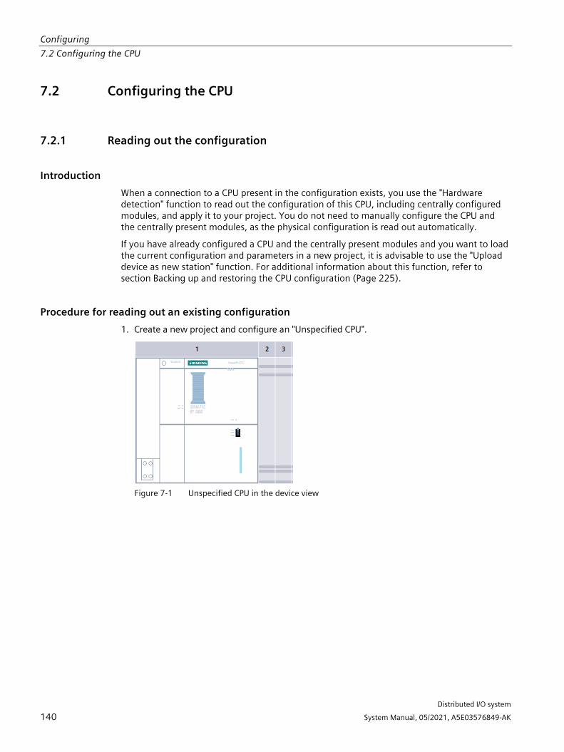
Configuring 7.2 Configuring the CPU
Distributed I/O system
140 System Manual, 05/2021, A5E03576849-AK
7.2 Configuring the CPU
7.2.1 Reading out the configuration
Introduction When a connection to a CPU present in the configuration exists, you use the "Hardware detection" function to read out the configuration of this CPU, including centrally configured modules, and apply it to your project. You do not need to manually configure the CPU and the centrally present modules, as the physical configuration is read out automatically.
If you have already configured a CPU and the centrally present modules and you want to load the current configuration and parameters in a new project, it is advisable to use the "Upload device as new station" function. For additional information about this function, refer to section Backing up and restoring the CPU configuration (Page 225).
Procedure for reading out an existing configuration 1. Create a new project and configure an "Unspecified CPU".
Figure 7-1 Unspecified CPU in the device view

Configuring 7.2 Configuring the CPU
Distributed I/O system
System Manual, 05/2021, A5E03576849-AK 141
2. In the device view (or in the network view), select the "Hardware detection" command in the "Online" menu.
Figure 7-2 Hardware detection in the Online menu
You can also double-click the CPU and click "Detect" in the message.
Figure 7-3 Hardware detection message in the device view
3. In the "Hardware detection for PLC_x" dialog box, click "Refresh". Then, select the CPU and the PG/PC interface and click "Detect". STEP 7 downloads the hardware configuration including the modules from the CPU to your project.
Figure 7-4 Result of the hardware detection in the device view

Configuring 7.2 Configuring the CPU
Distributed I/O system
142 System Manual, 05/2021, A5E03576849-AK
STEP 7 assigns a valid default parameter assignment for all modules. You can change the parameter assignment subsequently.
Note
If you want to go online after the hardware detection, you have to first download the detected configuration to the CPU; otherwise, an error may occur due to inconsistent configurations.
Properties of central modules The properties of the CPUs have special significance for system behavior. You can set the following for a CPU using STEP 7:
• Startup behavior
• Parameter assignment of the interface(s), for example, IP address, subnet mask
• Web server, e.g. activation, user administration, and languages
• OPC UA server
• Global Security Certificate Manager
• Cycle times, e.g. maximum cycle time
• System and clock memory
• Protection level for access protection with assigned password parameter
• Time and day settings (daylight saving/standard)
The properties that can be set and the corresponding value ranges are specified by STEP 7. Fields that cannot be edited are grayed out.
Reference Information about the individual settings can be found in the online help and in the manuals of the relevant CPUs.

Configuring 7.2 Configuring the CPU
Distributed I/O system
System Manual, 05/2021, A5E03576849-AK 143
7.2.2 Addressing
Introduction In order to address the automation components or I/O modules, they have to have unique addresses. The following section explains the various address areas.
I/O address I/O addresses (input/output addresses) are required in the user program to read inputs and set outputs.
STEP 7 automatically assigns input and output addresses when you connect the modules. Each module uses a continuous area in the input and/or output addresses corresponding to its volume of input and output data.
Figure 7-5 Example with input / output addresses from STEP 7
STEP 7 assigns the address areas of the modules by default to the process image partition 0 ("Automatic updating"). This process image partition is updated in the main cycle of the CPU.
Device address (e.g. Ethernet address) Device addresses are addresses of programmable modules with interfaces to a subnet (e.g., IP address or PROFIBUS address). They are required to address the various devices on a subnet, for example, to download a user program.

Configuring 7.2 Configuring the CPU
Distributed I/O system
144 System Manual, 05/2021, A5E03576849-AK
Hardware identifier STEP 7 automatically assigns a hardware identifier to identify and address modules and submodules. You use the hardware identifier in the case of diagnostic messages or operations, for example, to identify a defective module or the module addressed.
Figure 7-6 Example of a hardware identifier from STEP 7
In the "System constants" tab, you will find all hardware identifiers and their symbolic names (of the hardware identifier) for the selected module.
You can also find the hardware identifiers and names for all modules of a device in the default tag table of the "System constants" tab.
Figure 7-7 Example of an excerpt from a default tag table in STEP 7

Configuring 7.2 Configuring the CPU
Distributed I/O system
System Manual, 05/2021, A5E03576849-AK 145
7.2.3 Process images and process image partitions
7.2.3.1 Process image - overview
Process image of the inputs and outputs The process image input and output is an image of the signal states. The CPU transfers the values from the input and output modules to the process image input and output. At the start of the cyclic program, the CPU transfers the process image output as a signal state to the output modules. Afterwards the CPU transfers the signal states of the input modules to the process image input.
Advantages of the process image The process image accesses a consistent image of the process signals during cyclic program execution. If a signal state at an input module changes during program processing, the signal state is retained in the process image. The CPU does not update the process image until the next cycle.
You can only assign the addresses of a module to a single process image partition.
32 process image partitions By means of process image partitions, the CPU synchronizes the updated inputs/outputs of particular modules with defined user program sections.
The overall process image is subdivided into up to 32 process image partitions (PIP).
The CPU updates PIP 0 in each program cycle (automatic update) and assigns it to OB 1.
You can assign the process image partitions PIP 1 to PIP 31 to the other OBs during configuration of the input/output modules in STEP 7.
After the OB has been started, the CPU updates the assigned process image partition for inputs and reads in the process signals. At the end of the OB the CPU writes the outputs of the assigned process image partition directly to the peripheral outputs without having to wait for the completion of the cyclic program processing.

Configuring 7.2 Configuring the CPU
Distributed I/O system
146 System Manual, 05/2021, A5E03576849-AK
7.2.3.2 Automatically updating process image partitions You can assign one process image partition to each organization block. In this case, the user program automatically updates the process image partition. The exceptions are PIP 0 and isochronous OBs.
Updating the process image partition The process image partition is divided into two parts:
• Process image partition of the inputs (PIPI)
• Process image partition of the outputs (PIPQ)
The CPU always updates/reads the process image partition of the inputs (PIPI) before processing of the associated OB. The CPU outputs the process image of the outputs (PIPQ) at the end of the OB.
The figure below illustrates the updating of the process image partitions.
Figure 7-8 Updating process image partitions
7.2.3.3 Update process image partitions in the user program
Requirements Alternatively, you can also use the following instructions for the process image update:
• "UPDAT_PI" instruction
• "UPDAT_PO" instruction
You will find the instructions in STEP 7 in the "Instructions" task card under "Extended instructions". The instructions can be called from any point in the program.
Requirements for updating process image partitions with the "UPDAT_PI" and "UPDAT_PO" instructions:
• The process image partitions must not be assigned to any OB. This means the process image partitions are not automatically updated.
Note Update of PPI 0
PIP 0 (automatic update) cannot be updated with the "UPDAT_PI" and "UPDAT_PO" instructions.

Configuring 7.2 Configuring the CPU
Distributed I/O system
System Manual, 05/2021, A5E03576849-AK 147
UPDAT_PI: updates the process image partition of the inputs With this instruction you read the signal states from the input modules into the process image partition of the inputs (PIPI).
UPDAT_PO: updates the process image partition of the outputs With this instruction you transfer the process image partition of the outputs to the output modules.
Synchronous cycle interrupt OB In the synchronous cycle interrupt OBs, you use the "SYNC_PI" and "SYNC_PO" operations to update the process image partitions of the operations. For additional information on the synchronous cycle interrupt OBs, refer to the STEP 7 Online Help.
Direct I/O access to the inputs and outputs of the module As an alternative to access via the process image, you can directly access the I/O (write and read access) if this is necessary for program-related reasons. Direct (write) access to I/O also writes to the process image. This prevents a subsequent output of the process image from again overwriting the value written by direct access.
Reference Additional information on process image partitions is available in the function manual, Cycle and response times (https://support.automation.siemens.com/WW/view/en/59193558).

Configuring 7.3 Configuring the interface module
Distributed I/O system
148 System Manual, 05/2021, A5E03576849-AK
7.3 Configuring the interface module
Configuring Read the STEP 7 online help and/or the documentation of the configuration software manufacturer when configuring the interface module.
The F-destination address is saved permanently on the coding element of the ET 200SP fail-safe modules. Fail-safe motor starters do not need an F-destination address or a coding element.
Note
The supply voltage L+ must be applied to the F-module when the F-destination address is assigned.
Note
Note the following in conjunction with configuration control:
Before you can use configuration control together with F-modules, you must assign the F-destination address to the F-modules at the designated slots. For this, each F-module must be inserted in the slot configured for it. The actual configuration can then differ from the specified configuration.
For additional information on assigning the F-destination address, refer to the SIMATIC Safety - Configuring and Programming (https://support.automation.siemens.com/WW/view/en/54110126) Programming and Operating Manual and to the online help for the S7 Configuration Pack.

Configuring 7.4 Value status
Distributed I/O system
System Manual, 05/2021, A5E03576849-AK 149
7.4 Value status
Introduction Value status (QI, quality information) refers to status information of I/O channels that is made available to the user program via the process image input (PII). However, since the value status is partly derived from the diagnostics, there may be a time delay between the occurrence of the error and the message depending on the diagnostics.
Each bit of the value status is assigned to a channel and provides information about the validity of the process value of the respective channel (1 = no errors on the channel of the I/O module, 0 = value is bad).
The assignment of the value status bytes in the process image input depends on the module used. Detailed information can be found in the manual for the relevant I/O module.
Summary: Possible cause for value status = 0:
• A channel has an error (overflow/underflow, wire break, short-circuit, etc.)
• The supply voltage L+ is missing at the terminals or is not sufficient
• A channel has been deactivated
• PROFIenergy pause is activated
• Outputs are inactive (value status = 0: Module not plugged in. Value status is generated via interface module in distributed mode)
If, for example, there is a wire break at an input but the wire break diagnostics is disabled, the value status of the channel is set to "0" but no diagnostics is triggered. Diagnostics is only also triggered if the wire break diagnostics is enabled.
With module-by-module channel diagnostics of the I/O modules, these also map the value status module-by-module. The channels are mapped here module-by-module to value status = 0 or value status = 1.
Which interface modules support the value status? The following interface modules support the value status:
• IM 155-6 PN ST
• IM 155-6 PN HS
• IM 155-6 PN/2 HF
• IM 155-6 PN/3 HF
• IM 155-6 MF HF
Which I/O modules support the value status? The I/O modules of the function classes Standard, High Feature and High Speed support the value status.

Configuring 7.4 Value status
Distributed I/O system
150 System Manual, 05/2021, A5E03576849-AK
Activating value status
Table 7- 3 Value status depending on the respective configuration variant
- STEP 7 TIA (integrated I/O module; PROFINET and PROFIBUS)
STEP 7 HSP (PROFINET and PROFIBUS)
GSD PROFINET (can be integrated in STEP 7 TIA and STEP 7)
GSD PROFIBUS (can be integrated in STEP 7 TIA and STEP 7)
Select the I/O module from the hardware catalog and activate the value status
There is only one entry in the hardware catalog for each I/O module. In the configuration dia-log, you can set whether the I/O module is to be operated with or without value status.
There is only one entry in the hardware catalog for each I/O module. In the configuration dia-log, you can set whether the I/O module is to be operated with or without value status.
There are multiple en-tries in the hardware catalog for each I/O module. On selection in the hardware catalog, it must be determined whether the I/O module is to be operated with or without value status. The value status can be recognized by the suffix "QI".
No value status is supported for con-figuration via GSD PROFIBUS. (see also "Special features DI 8xNAMUR HF")
Input substitute value behavior
The "Input values with module failure" parameter (input substitute value behavior) is available for CPUs 1500 from FW ver-sion V2.0. If the I/O module is con-figured with value status, the parameter is fixed at "Input value 0". Input substitute value behavior can only be configured if no value status is configured
The "Input values with module failure" parame-ter is not available.
The "Input values with module failure" parame-ter (input substitute value behavior) is avail-able for CPUs 1500 from FW version V2.0. The same restrictions apply as for I/O modules integrated in STEP 7 TIA. Due to the limited capa-bilities of the GSD, how-ever, these are not locked in the GSD inter-face.
The "Input values with module failure" parameter is not available.
Special features DI 8xNAMUR HF (I/O module always provides value status)
Input substitute value behavior cannot be con-figured.
- Input substitute value behavior cannot be configured. Due to the limited possibilities of the GSD, however, this is not locked in the GSD interface.
I/O module "DI 8xNAMUR HF" is the only module which is available via GSD with activated value status.
Special features for modules with MSI/MSO The meaning of the value status of the basic submodule is described above. The value status of the MSI/MSO submodules are copies of the base submodule. The value status of the MSI/MSO submodules remains set to "0" as long as the base submodule has not been configured.

Distributed I/O system
System Manual, 05/2021, A5E03576849-AK 151
Basics of program execution 8 8.1 Events and OBs
Start events The table below gives an overview of the possible event sources for start events and their OBs.
Table 8- 1 Start events
Types of event sources Possible priorities (default priority)
Possible OB numbers
Default system response 1)
Number of OBs
Starting 2) 1 100, ≥ 123 Ignore 0 to 100 Cyclic program 2) 1 1, ≥ 123 Ignore 0 to 100 Time-of-day interrupt 2) 2 to 24 (2) 10 to 17, ≥ 123 Not applicable 0 to 20 Time-delay interrupt 2) 2 to 24 (3) 20 to 23, ≥ 123 Not applicable 0 to 20 Cyclic interrupt 2) 2 to 24 (8 to 17, frequency
dependent) 30 to 38, ≥ 123 Not applicable 0 to 20
Hardware interrupt 2) 2 to 26 (18) 40 to 47, ≥ 123 Ignore 0 to 50 Status interrupt 2 to 24 (4) 55 Ignore 0 or 1 Update interrupt 2 to 24 (4) 56 Ignore 0 or 1 Manufacturer-specific or profile-specific interrupt
2 to 24 (4) 57 Ignore 0 or 1
Synchronous cycle interrupt 16 to 26 (21) 61 to 64, ≥ 123 Ignore 0 to 2 Time error 3) 22 80 Ignore 0 or 1 Cycle monitoring time ex-ceeded once
STOP
Diagnostics interrupt 2 to 26 (5) 82 Ignore 0 or 1 Pull/plug interrupt for mod-ules
2 to 26 (6) 83 Ignore 0 or 1
Rack error 2 to 26 (6) 86 Ignore 0 or 1 MC-servo 4) 17 to 26 (25) 91 Not applicable 0 or 1 MC-PreServo 4) 17 to 26 (25) 67 Not applicable 0 or 1 MC-PostServo 4) 17 to 26 (25) 95 Not applicable 0 or 1 MC-Interpolator 4) 16 to 26 (24) 92 Not applicable 0 or 1

Basics of program execution 8.1 Events and OBs
Distributed I/O system
152 System Manual, 05/2021, A5E03576849-AK
Types of event sources Possible priorities (default priority)
Possible OB numbers
Default system response 1)
Number of OBs
Programming error (only for global error handling)
2 to 26 (7) 121 STOP 0 or 1
I/O access error (only for global error handling)
2 to 26 (7) 122 Ignore 0 or 1
1) If you have not configured the OB. 2) In the case of these event sources, besides the permanently assigned OB numbers (see column: Possible OB numbers) in
STEP 7 you can assign OB numbers from the range ≥ 123. 3) If the maximum cycle time has been exceeded twice within one cycle, the CPU always assumes the STOP state, regard-
less of whether you have configured OB 80. 4) You will find more information on these event sources and the starting behavior in the S7-1500 Motion Control function
manual.
Response to triggers The occurrence of a start event results in the following reaction:
• If the event comes from an event source to which you have assigned an OB, this event triggers the execution of the assigned OB. The event enters the queue according to its priority.
• If the event comes from an event source to which you have not assigned an OB, the CPU executes the default system reaction.
Note
Some event sources, such as startup, pull/plug, exist even if you do not configure them.
Assignment between event source and OBs The type of OB determines where you make the assignment between OB and event source:
• With hardware interrupts and isochronous mode interrupts, the assignment is made during the configuration of the hardware or when the OB is created.
• In the case of the MC-Servo, MC-PreServo, MC-PostServo and MC-Interpolator, STEP 7 automatically assigns the OBs 91/92 as soon as you add a technology object.
• For all other types of OB, the assignment is made when the OB is created, where applicable after you have configured the event source.
For hardware interrupts, you can change an assignment which has already been made during runtime with the instructions ATTACH and DETACH. In this case, only the actually effective assignment changes, and not the configured assignment. The configured assignment takes effect after loading, and at startup.
The CPU ignores hardware interrupts to which you did not assign an OB in your configuration or which occur after the DETACH instruction. The CPU does not check whether an OB is assigned to this event when an event arrives, but only prior to the actual processing of the hardware interrupt.

Basics of program execution 8.2 Asynchronous instructions
Distributed I/O system
System Manual, 05/2021, A5E03576849-AK 153
OB priority and runtime behavior If you have assigned an OB to the event, the OB has the priority of the event. The CPU supports the priority classes 1 (lowest priority) to 26 (highest priority). The following items are essential to the processing of an event:
• Calling and processing of the assigned OB
• The update of the process image partition of the assigned OB
The user program processes the OBs exclusively on a priority basis. This means the program processes the OB with the highest priority first when multiple OB requests occur at the same time. If an event occurs that has a higher priority than the currently active OB, this OB is interrupted. The user program processes events of the same priority in order of occurrence.
Note Communication
Communication (e.g. test functions with the PG) always works permanently with the priority 15. So as not to unnecessarily prolong program runtime in the case of time-critical applications, these OBs should not be interrupted by communication. Assign a priority >15 for these OBs.
Reference You can find more information on organization blocks in the STEP 7 online help.
8.2 Asynchronous instructions
Introduction In program processing, a differentiation is made between synchronous and asynchronous instructions.
The "synchronous" and "asynchronous" properties relate to the temporal relationship between the call and execution of the instruction.
The following applies to synchronous instructions: When the call of a synchronous instruction is ended, the execution is also ended.
This is different in the case of asynchronous instructions: When the call of an asynchronous instruction is ended, the execution of the asynchronous instruction is not necessarily ended yet. This means the execution of an asynchronous instruction can extend over multiple calls. The CPU processes asynchronous instructions in parallel with the cyclic user program. Asynchronous instructions generate jobs in the CPU for their processing.
Asynchronous instructions are usually instructions for transferring data (data records for modules, communication data, diagnostics data).

Basics of program execution 8.2 Asynchronous instructions
Distributed I/O system
154 System Manual, 05/2021, A5E03576849-AK
Difference between synchronous/asynchronous instructions The figure below shows the difference between processing an asynchronous instruction and processing a synchronous instruction. In this figure the asynchronous instruction is called five times before the execution is completed, for example, a data record is completely transferred.
With a synchronous instruction, the instruction is fully executed in each call.
① First call of the asynchronous instruction, start of processing ② Intermediate call of asynchronous instruction, continuation of processing ③ Last call of the asynchronous instruction, termination of processing ④ The synchronous instruction is completely processed at each call
Duration of the complete processing
Figure 8-1 Difference between synchronous and asynchronous instructions

Basics of program execution 8.2 Asynchronous instructions
Distributed I/O system
System Manual, 05/2021, A5E03576849-AK 155
Parallel processing of asynchronous instruction jobs A CPU can process several asynchronous instruction jobs in parallel. The CPU processes the jobs in parallel under the following conditions:
• Several asynchronous instruction jobs are called at the same time.
• The maximum number of concurrently running jobs for the instruction is not exceeded.
The figure below shows the parallel processing of two jobs of the instruction WRREC. The two instructions are processed in parallel for a specific period here.
Figure 8-2 Parallel processing of the asynchronous instruction WRREC
Note Dependencies between asynchronous instructions
The call sequence in the user program may differ from the processing sequence of the asynchronous instructions. This can lead to problems with dependencies between asynchronous instructions.
Solution: To ensure correct timing of processing, use the status outputs of the asynchronous instructions in a sequencer. If an asynchronous instruction is finished and this is acknowledged via the parameter DONE, then only the next asynchronous instruction should start.
Example: For the RecipeImport and RecipeExport recipe functions, you need a CSV file for the recipe data. If you use the same CSV file for import and export, then the two asynchronous statements are dependent on each other. Link the status of the DONE parameter of the RecipeImport instruction in a sequencer to the next step where the RecipeExport is executed. The link thus ensures correct processing.

Basics of program execution 8.2 Asynchronous instructions
Distributed I/O system
156 System Manual, 05/2021, A5E03576849-AK
Assignment of call to job of the instruction To execute an instruction over multiple calls, the CPU must be able to uniquely assign a subsequent call to a running job of the instruction.
To assign a call to a job, the CPU uses one of the following two mechanisms, depending on the type of the instruction:
• Via the instance data block of the instruction (in the case of the "SFB" type)
• The input parameters of the instruction identifying the job. These input parameters must match in each call during processing of the asynchronous instruction. Example: A "Create_DB" instruction job is identified by the input parameters LOW_LIMIT, UP_LIMIT, COUNT, ATTRIB and SRCBLK.
The following table shows which instruction you can identify with which input parameters.
Instruction Job is identified by DPSYC_FR LADDR, GROUP, MODE D_ACT_DP LADDR DPNRM_DG LADDR WR_DPARM LADDR, RECNUM WR_REC LADDR, RECNUM RD_REC LADDR, RECNUM CREATE_DB LOW_LIMIT, UP_LIMIT, COUNT, ATTRIB, SRCBLK READ_DBL SRCBLK, DSTBLK WRIT_DBL SRCBLK, DSTBLK RD_DPARA LADDR, RECNUM DP_TOPOL DP_ID

Basics of program execution 8.2 Asynchronous instructions
Distributed I/O system
System Manual, 05/2021, A5E03576849-AK 157
Status of an asynchronous instruction An asynchronous instruction shows its status via the block parameters STATUS/RET_VAL and BUSY. Many asynchronous instructions also use the block parameters DONE and ERROR.
The figure below shows the two asynchronous instructions WRREC and CREATE_DB.
① The input parameter REQ starts the job to execute the asynchronous instruction. ② The output parameter DONE indicates that the job was completed without error. ③ The output parameter BUSY indicates whether the job is currently being processed. When BUSY
=1, a resource is assigned for the asynchronous instruction. If BUSY = 0, then the resource is free.
④ The output parameter ERROR indicates that an error has occurred. ⑤ The output parameter STATUS/RET_VAL provides information on the status of the job execu-
tion. The output parameter STATUS/RET_VAL receives the error information after the occur-rence of an error.
Figure 8-3 Block parameters of asynchronous instructions using the instructions WRREC and CREATE_DB as examples.
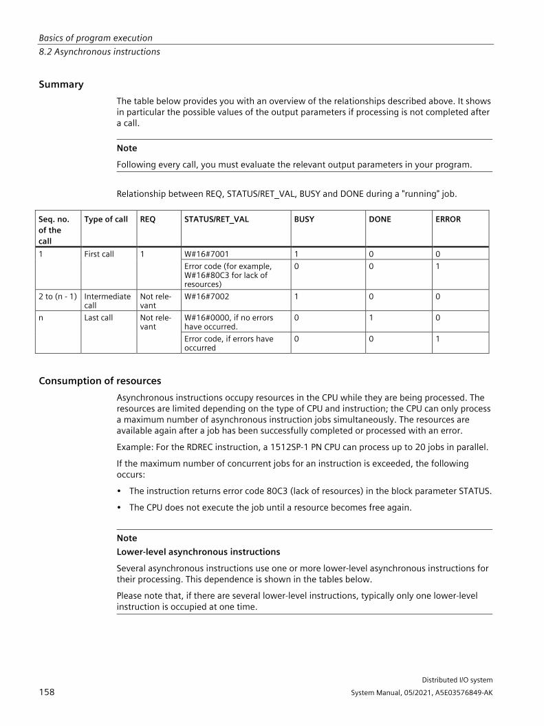
Basics of program execution 8.2 Asynchronous instructions
Distributed I/O system
158 System Manual, 05/2021, A5E03576849-AK
Summary The table below provides you with an overview of the relationships described above. It shows in particular the possible values of the output parameters if processing is not completed after a call.
Note
Following every call, you must evaluate the relevant output parameters in your program.
Relationship between REQ, STATUS/RET_VAL, BUSY and DONE during a "running" job. Seq. no. of the call
Type of call REQ STATUS/RET_VAL BUSY DONE ERROR
1
First call
1
W#16#7001 1 0 0 Error code (for example, W#16#80C3 for lack of resources)
0 0 1
2 to (n - 1) Intermediate call
Not rele-vant
W#16#7002 1 0 0
n
Last call
Not rele-vant
W#16#0000, if no errors have occurred.
0 1 0
Error code, if errors have occurred
0 0 1
Consumption of resources Asynchronous instructions occupy resources in the CPU while they are being processed. The resources are limited depending on the type of CPU and instruction; the CPU can only process a maximum number of asynchronous instruction jobs simultaneously. The resources are available again after a job has been successfully completed or processed with an error.
Example: For the RDREC instruction, a 1512SP-1 PN CPU can process up to 20 jobs in parallel.
If the maximum number of concurrent jobs for an instruction is exceeded, the following occurs:
• The instruction returns error code 80C3 (lack of resources) in the block parameter STATUS.
• The CPU does not execute the job until a resource becomes free again.
Note Lower-level asynchronous instructions
Several asynchronous instructions use one or more lower-level asynchronous instructions for their processing. This dependence is shown in the tables below.
Please note that, if there are several lower-level instructions, typically only one lower-level instruction is occupied at one time.

Basics of program execution 8.2 Asynchronous instructions
Distributed I/O system
System Manual, 05/2021, A5E03576849-AK 159
Extended instructions: maximum number of concurrently running jobs
Table 8- 2 Maximum number of concurrently running jobs for asynchronous extended instructions and lower-level in-structions used
Extended instructions CPU 1510SP-1 PN CPU 1510SP F-1 PN
CPU 1512SP-1 PN CPU 1512SP F-1 PN
Distributed I/O RDREC 20 RD_REC 10 WRREC 20 WR_REC 10 D_ACT_DP 8 ReconfigIOSystem uses RDREC, WRREC, D_ACT_DP, DPSYC_FR 2 DPNRM_DG 8 DP_TOPOL 1 ASI_CTRL uses RDREC, WRREC PROFIenergy PE_START_END uses RDREC, WRREC PE_CMD uses RDREC, WRREC PE_DS3_Write_ET200S uses RDREC, WRREC PE_WOL uses RDREC, WRREC, TUSEND, TURCV, TCON, TDISCON Module parameter assignment RD_DPAR 10 RD_DPARA 10 RD_DPARM 10 WR_DPARM 10 Diagnostics Get_IM_Data 10 GetStationInfo 10 Recipes and data logging RecipeExport 10 RecipeImport 10 DataLogCreate 10 DataLogOpen 10 DataLogWrite 10 DataLogClear 10 DataLogClose 10 DataLogDelete 10 DataLogNewFile 10 Data block functions CREATE_DB 10 READ_DBL 10 WRIT_DBL 10 DELETE_DB 10 File handling

Basics of program execution 8.2 Asynchronous instructions
Distributed I/O system
160 System Manual, 05/2021, A5E03576849-AK
Extended instructions CPU 1510SP-1 PN CPU 1510SP F-1 PN
CPU 1512SP-1 PN CPU 1512SP F-1 PN
FileReadC 10 FileWriteC 10
Basic instructions: maximum number of concurrently running jobs
Table 8- 3 Lower-level instructions used for asynchronous basic instructions
Basic instructions CPU 1510SP-1 PN CPU 1510SP F-1 PN
CPU 1512SP-1 PN CPU 1512SP F-1 PN
Array DB ReadFromArrayDBL uses READ_DBL (see Extended instructions) WriteToArrayDBL uses READ_DBL, WRIT_DBL (see Extended instructions)
Communication: maximum number of concurrently running jobs
Table 8- 4 Maximum number of concurrently running jobs for asynchronous instructions and lower-level instructions used for Open User Communication
Open User Communication CPU 1510SP-1 PN CPU 1510SP F-1 PN
CPU 1512SP-1 PN CPU 1512SP F-1 PN
TSEND TUSEND
64 88
TRCV TURCV
64 88
TCON 64 88 TDISCON 64 88 T_RESET 64 88 T_DIAG 64 88 T_CONFIG 1 TSEND_C uses TSEND, TUSEND, TRCV, TCON, TDISCON TRCV_C uses TSEND, TUSEND, TRCV, TURCV, TCON, TDISCON TMAIL_C uses TSEND, TUSEND, TRCV, TURCV, TCON, TDISCON
Table 8- 5 Lower-level instructions used for asynchronous instructions for MODBUS TCP
MODBUS TCP CPU 1510SP-1 PN CPU 1510P F-1 PN
CPU 1512SP-1 PN CPU 1512SP F-1 PN
MB_CLIENT uses TSEND, TUSEND, TRCV, TURCV, TCON, TDISCON MB_SERVER uses TSEND, TUSEND, TRCV, TURCV, TCON, TDISCON

Basics of program execution 8.2 Asynchronous instructions
Distributed I/O system
System Manual, 05/2021, A5E03576849-AK 161
Table 8- 6 Maximum number of concurrently running jobs for asynchronous instructions for S7 communication. The S7 communication instructions use a common pool of resources.
S7 communication CPU 1510SP-1 PN CPU 1510SP F-1 PN
CPU 1512SP-1 PN CPU 1512SP F-1 PN
PUT GET USEND URCV BSEND BRCV
192 264
Table 8- 7 Lower-level instructions used for asynchronous instructions for communications processors
Communications proces-sors
CPU 1510SP-1 PN CPU 1510SP F-1 PN
CPU 1512SP-1 PN CPU 1512SP F-1 PN
PtP communication Port_Config uses RDDEC, WRREC Send_Config uses RDDEC, WRREC Receive_Config uses RDDEC, WRREC Send_P2P uses RDDEC, WRREC Receive_P2P uses RDDEC, WRREC Receive_Reset uses RDDEC, WRREC Signal_Get uses RDDEC, WRREC Signal_Set uses RDDEC, WRREC Get_Features uses RDDEC, WRREC Set_Features uses RDDEC, WRREC USS communication USS_Port_Scan uses RDDEC, WRREC USS_Port_Scan_31 uses RDDEC, WRREC MODBUS (RTU) Modbus_Comm_Load uses RDDEC, WRREC Modbus_Master uses RDDEC, WRREC Modbus_Slave uses RDDEC, WRREC ET 200S serial interface S_USSI uses CREATE_DB SIMATIC NET FTP_CMD uses TSEND, TRCV, TCON, TDISCON

Basics of program execution 8.2 Asynchronous instructions
Distributed I/O system
162 System Manual, 05/2021, A5E03576849-AK
Table 8- 8 Maximum number of concurrently running jobs for asynchronous instructions for OPC UA
OPC_UA CPU 1510SP-1 PN CPU 1510SP F-1 PN
CPU 1512SP-1 PN CPU 1512SP F-1 PN
OPC_UA_Connect 10 OPC_UA_Disconnect 10 OPC_UA_NamespaceGetIndexList 10 OPC_UA_NodeGetHandleList 10 OPC_UA_NodeReleaseHandleList 10 OPC_UA_TranslatePathList 10 OPC_UA_ReadList 10 OPC_UA_WriteList 10 OPC_UA_MethodGetHandleList 10 OPC_UA_MethodReleaseHandleList 10 OPC_UA_MethodCall 10 OPC_UA_ServerMethodPre 10 OPC_UA_ServerMethodPost 10 OPC_UA_ConnectionGetStatus 10

Basics of program execution 8.2 Asynchronous instructions
Distributed I/O system
System Manual, 05/2021, A5E03576849-AK 163
Technology: maximum number of concurrently running jobs
Table 8- 9 Maximum number of concurrently running jobs for asynchronous instructions for technology. The instructions for technology use a common pool of resources.
Technology CPU 1510SP-1 PN CPU 1510SP F-1 PN CPU 1512SP-1 PN
CPU 1512SP F-1 PN Motion Control MC_Power MC_Reset MC_Home MC_Halt MC_MoveAbsolute MC_MoveRelative MC_MoveVelocity MC_MoveJog MC_MoveSuperimposed MC_Stop MC_WriteParameter MC_SetAxisSTW MC_MeasuringInput MC_MeasuringInputCyclic MC_AbortMeasuringInput MC_OutputCam MC_CamTrack MC_GearIn MC_TorqueLimiting MC_TorqueAdditive MC_TorqueRange
300
Additional information You can find additional information on block parameter assignment in the STEP 7 online help.

Distributed I/O system
System Manual, 05/2021, A5E03576849-AK 164
Protection 9 9.1 Overview of the protective functions of the CPU
Introduction This chapter describes the following functions for protecting the ET 200SP against unauthorized access:
• Protection of confidential configuration data
• Access protection
• Know-how protection
• Copy protection
Further measures for protecting the CPU The following measures additionally increase the protection against unauthorized access to functions and data of the CPU from external sources and via the network:
• Deactivation of the Web server
• Deactivation of the OPC UA server (you will find further information on the security mechanisms for OPC UA servers in the Communication (https://support.industry.siemens.com/cs/ww/en/view/59192925) function manual)
• Deactivation of time synchronization via an NTP server
• Deactivation of PUT/GET communication
When using the Web server, you protect your ET 200SP distributed I/O system against unauthorized access
• By setting password-protected access rights for certain users in user management.
• By using the default "Allow access via HTTPS only" option. This option allows access to the Web server with the secure Hypertext transfer protocol HTTPS only.

Protection 9.2 Protection of confidential configuration data
Distributed I/O system
System Manual, 05/2021, A5E03576849-AK 165
9.2 Protection of confidential configuration data As of STEP 7 V17, you have the option of assigning a password for protecting confidential configuration data of the respective CPU. This refers to data such as private keys that are required for the proper functioning of certificate-based protocols.
You can find detailed information on protecting confidential configuration data in the Communication (https://support.industry.siemens.com/cs/ww/en/view/59192925) function manual.
Note Replacement part scenario
Replacing the CPU in a replacement part scenario has an impact on the password for protection of confidential configuration data. When you replace the CPU, observe the rules for the replacement part scenario in the Communication (https://support.industry.siemens.com/cs/ww/en/view/59192925) function manual.
9.3 Configuring access protection for the CPU
Introduction The CPU offers four access levels to limit access to specific functions.
By setting up the access levels and the passwords for a CPU, you limit the functions and memory areas that are accessible without entering a password. You specify the individual access levels as well as the entry of their associated passwords in the object properties of the CPU.
Rules for passwords Ensure that passwords are sufficiently secure. Passwords must not follow a machine-recognizable pattern. Follow the rules below:
• Assign a password that is at least 8 characters long.
• Use different cases and characters: uppercase/lowercase, numbers and special characters.

Protection 9.3 Configuring access protection for the CPU
Distributed I/O system
166 System Manual, 05/2021, A5E03576849-AK
Access levels of the CPU
Table 9- 1 Access levels and access restrictions
Access levels Access restrictions Full access (no protection)
Any user can read and change the hardware configuration and the blocks.
Read access With this access level, read-only access to the hardware configuration and the blocks is possible without entering a password, which means you can download the hardware configuration and blocks to the programming device. In addition, HMI access and access to diagnostics data is possible. Without entering the password, you cannot load any blocks or hardware configura-tion into the CPU. Additionally, the following are not possible without the pass-word: • Writing test functions • Firmware update (online)
HMI access With this access level only HMI access and access to diagnostics data are possible without entering the password. Without entering the password, you can neither load blocks nor the hardware con-figuration into the CPU, nor load blocks and hardware configuration from the CPU into the programming device. Additionally, the following are not possible without the password: • Writing test functions • Changing the mode (RUN/STOP) • Firmware update (online) • Display of the online/offline comparison status
No access (com-plete protection)
When the CPU has complete protection, no read or write access to the hardware configuration and the blocks is possible (without access authorization in the form of a password). HMI access is also not possible. The server function for PUT/GET communication is disabled in this access level (cannot be changed). Authentication with the password will again provide you full access to the CPU.
An enumeration of which functions are available in the different protection levels is available in the "Setting options for the protection" entry in the STEP 7 online help.
Properties of the access levels Each access level allows unrestricted access to certain functions without entering a password, for example, identification using the "Accessible devices" function.
The default setting of the CPUs is "No access (complete protection)". In the default access level, the user is not allowed to read or modify the hardware configuration or the blocks. To obtain access to the CPUs, assign parameters alternatively in the properties of the CPU:
• A password for the protection level "No access (complete protection)"
• Another protection level, e.g. "Full access (no protection)".
Communication between the CPUs (via the communication functions in the blocks) is not restricted by the access level of the CPU, unless PUT/GET communication is deactivated in the "No access" (complete protection) access level.

Protection 9.3 Configuring access protection for the CPU
Distributed I/O system
System Manual, 05/2021, A5E03576849-AK 167
Entry of the right password allows access to all the functions that are allowed in the corresponding level.
Note Configuring an access level does not replace know-how protection
Configuring access levels offers a high degree of protection against unauthorized changes to the CPU by restricting the rights to download the hardware and software configuration to the CPU. However, blocks on the SIMATIC memory card are not write- or read-protected. Use know-how protection to protect the code of blocks on the SIMATIC memory card.
Behavior of functions with different access levels The STEP 7 online help includes a table which lists the online functions that are available in the different access levels.
Selecting the access levels To configure the access levels of a CPU, follow these steps:
1. Open the properties of the CPU in the Inspector window.
2. Open the "Protection" entry in the area navigation.
A table with the possible access levels is available in the Inspector window.
Figure 9-1 Possible access levels
3. Activate the desired protection level in the first column of the table. The green check marks in the columns to the right of the access level show you which operations are still available without entering the password. In the example (see above), read access and HMI access are still possible without a password.
4. In the "Enter password" column, specify a password for the access level "Full access" in the first row. In the "Confirm password" column, enter the selected password again to guard against incorrect entries.

Protection 9.4 Using the user program to set additional access protection
Distributed I/O system
168 System Manual, 05/2021, A5E03576849-AK
5. Assign additional passwords as required for other access levels.
6. Download the hardware configuration for the access level to take effect.
The CPU logs the following actions with an entry in the diagnostic buffer:
• Input of the correct or incorrect password, as the case may be
• Changes in the configuration of access levels
Behavior of a password-protected CPU during operation The CPU protection takes effect after you have downloaded the settings to the CPU.
Before an online function is executed, the CPU checks the necessary permission and, if necessary, prompts the user to enter a password. You can only execute password-protected functions from one programming device/PC at any time. Another programming device/PC cannot log on.
Access authorization to the protected data is in effect for the duration of the online connection or until you rescind the access authorization manually with "Online > Delete access rights".
Access levels for F-CPUs For the fail-safe CPUs, there is an additional access level in addition to the four described access levels. For additional information on this access level, refer to the description of the fail-safe system SIMATIC Safety Programming and Operating Manual SIMATIC Safety - Configuring and Programming (https://support.automation.siemens.com/WW/view/en/54110126).
9.4 Using the user program to set additional access protection
Access protection via user program You can also restrict access to a password-protected CPU in STEP 7 via the ENDIS_PW operation. You can find a description of this block in the online help under the keyword "ENDIS_PW: Limit and enable password legitimation".

Protection 9.5 Know-how protection
Distributed I/O system
System Manual, 05/2021, A5E03576849-AK 169
9.5 Know-how protection
Application You can use know-how protection to protect one or more OB, FB or FC blocks as well as global data blocks in your program from unauthorized access. Enter a password to restrict access to a block. The password offers high-level protection against unauthorized reading or manipulation of the block.
Password provider As an alternative to manual entry of password, you can connect a password provider to STEP 7. When using a password provider, you select a password from a list of available passwords. When a protected block is opened, STEP 7 connects to the password provider and retrieves the corresponding password.
To connect a password provider you have to install and activate it. A settings file in which you define the use of a password provider is also required.
A password provider offers the following advantages:
• The password provider defines and manages the passwords. When know-how protected blocks are opened, you work with symbolic names for passwords. A password is marked, for example, with the symbolic name "Machine_1" n the password provider. The actual password behind "Machine1" remains hidden from you. A password provider therefore offers you optimum block protection as the users do not know the password themselves.
• STEP 7 automatically opens know-how protected blocks without the direct entry of a password. This saves you time.
You will find more information on connecting a password provider in the STEP 7 online help.
Readable data If a block is know-how protected, only the following data is readable without the correct password:
• Block title, comments and block properties
• Block parameters (INPUT, OUTPUT, IN, OUT, RETURN)
• Call structure of the program
• Global tags without information on the point of use

Protection 9.5 Know-how protection
Distributed I/O system
170 System Manual, 05/2021, A5E03576849-AK
Further actions Further actions that can be carried out with a know-how protected block:
• Copying and deleting
• Calling in a program
• Online/offline comparison
• Load
Global data blocks and array data blocks You protect global data blocks (global DBs) from unauthorized access with know-how protection. If you do not have the valid password, you can read the global data block but not change it.
Know-how protection is not available for array data blocks (array DBs).
Setting up block know-how protection To set up block know-how protection, follow these steps:
1. Open the properties of the block in question.
2. Select the "Protection" option under "General".
Figure 9-2 Setting up block know-how protection (1)
3. Click the "Protection" button to display the "Know-how protection" dialog.
Figure 9-3 Setting up block know-how protection (2)

Protection 9.5 Know-how protection
Distributed I/O system
System Manual, 05/2021, A5E03576849-AK 171
4. Click the "Define" button to open the "Define Password" dialog.
Figure 9-4 Setting up block know-how protection (3)
5. Enter the new password in the "New password" box. Enter the same password in the "Confirm password" box.
6. Click "OK" to confirm your entry.
7. Close the "Know-how protection" dialog by clicking "OK".
Result: The selected blocks are now know-how protected. Know-how protected blocks are marked with a lock in the project tree. The password entered applies to all blocks selected.
Note Password provider
Alternatively, you can set up know-how protection for blocks with a password provider.
Opening know-how protected blocks To open a know-how protected block, follow these steps:
1. Double-click the block to open the "Access protection" dialog.
2. Enter the password for the know-how protected block.
3. Click "OK" to confirm your entry.
Result: The know-how-protected block is open.
Once you have opened the block, you can edit the program code and the block interface of the block for as long as the block or STEP 7 is open. You must enter the password again the next time you open the block. If you close the "Access protection" dialog with "Cancel", you will be able to open the block but you cannot display the block code or edit the block.
If you copy the block or add it to a library, for example, this does not cancel the know-how protection of the block. The copies will also be know-how-protected.

Protection 9.5 Know-how protection
Distributed I/O system
172 System Manual, 05/2021, A5E03576849-AK
Removing block know-how protection To remove block know-how protection, follow these steps:
1. Select the block from which you want to remove know-how protection. The protected block must not be open in the program editor.
2. In the "Edit" menu, select the "Know-how protection" command to open the "Know-how protection" dialog.
3. Clear the "Hide code (Know-how protection)" check box.
Figure 9-5 Removing block know-how protection (1)
4. Enter the password.
Figure 9-6 Removing block know-how protection (2)
5. Click "OK" to confirm your entry.
Result: Know-how protection is removed from the selected block.
See also Copy protection (Page 173)

Protection 9.6 Copy protection
Distributed I/O system
System Manual, 05/2021, A5E03576849-AK 173
9.6 Copy protection
Application The copy protection allows you to protect your program against unauthorized duplication. With copy protection you associate the blocks with a specific SIMATIC memory card or CPU. Through the linking of the serial number of a SIMATIC memory card or of a CPU the use of this program or of this block is only possible in conjunction with a specific SIMATIC memory card or CPU.
Copy and know-how protection Recommendation: to prevent unauthorized reset of copy protection, additionally apply know-how protection to a copy-protected block. To do this, first set up copy protection and then apply know-how protection for the block. You can find further information on setting up know-how protection in section Know-how protection (Page 169)
Setting up copy protection To set up copy protection, follow these steps:
1. Open the properties of the block in question.
2. Select the "Protection" option under "General".
Figure 9-7 Setting up copy protection (1)
3. In the "Copy protection" area, select either the "Bind to serial number of the CPU" entry or the "Bind to serial number of the memory card" entry from the drop-down list.
Figure 9-8 Setting up copy protection (2)

Protection 9.6 Copy protection
Distributed I/O system
174 System Manual, 05/2021, A5E03576849-AK
4. Activate the option "Serial number is inserted when downloading to a device or a memory card" if the serial number is to be inserted automatically during the uploading process (dynamic binding). Assign a password using the "Define password" button to link the use of a block additionally to the input of a password. Activate the option "Enter serial number" if you want to manually bind the serial number of the CPU or the SIMATIC memory card to a block (static binding).
5. You can now set up the know-how protection for the block in the "Know-how protection" area.
Note
If you download a copy-protected block to a device that does not match the specified serial number, the entire download operation will be rejected. This means that blocks without copy protection will also not be downloaded.
Removing copy protection To remove copy protection, follow these steps:
1. Remove any existing know-how protection.
2. Open the properties of the block in question.
3. Select the "Protection" option under "General".
4. In the "Copy protection" area, select the "No binding" entry from the drop-down list.
Figure 9-9 Removing copy protection

Distributed I/O system
System Manual, 05/2021, A5E03576849-AK 175
Configuration control (option handling) 10
Introduction Configuration control (option handling) is used to operate various standard machine configuration levels in one project without changing the configuration or the user program.
Operating principle of configuration control You can use configuration control to operate different standard machine configurations with a single configuration of the ET 200SP distributed I/O system.
• A station master is configured in a project (maximum configuration). The station master comprises all modules needed for all possible plant parts of a modular standard machine.
• The project's user program provides for several station options for various standard machine configuration levels as well as selection of a station option. A station option uses, for example, only some of the configured modules of the station master and these modules are inserted in the slots in a different order.
• The standard machine manufacturer selects a station option for a configuration of the standard machine. To do this, the project need not be modified, and it is not necessary to load a modified configuration.
You use a control data record you have programmed to notify the CPU/interface module as to which modules are missing or located on different slots in a station option as compared to the station master. The configuration control does not have an impact on the parameter assignment of the modules.
Configuration control allows you to flexibly vary the centralized/distributed configuration. This is only possible if the station option can be derived from the station master.

Configuration control (option handling)
Distributed I/O system
176 System Manual, 05/2021, A5E03576849-AK
The following figure shows three configurations of a standard machine with the corresponding station options of the ET 200SP distributed I/O system.
Figure 10-1 Various configuration levels of a standard machine with the corresponding station
options of the ET 200SP distributed I/O system.

Configuration control (option handling)
Distributed I/O system
System Manual, 05/2021, A5E03576849-AK 177
Advantages • Simple project management and commissioning by using a single STEP 7 project for all
station options.
• Simple handling for maintenance, versioning and upgrade:
• Hardware savings: Only those I/O modules are installed that are required for the machine's current station option.
• Savings potential in the creation, commissioning and the documentation for standard machines.
• Simple station expansion by using pre-wired empty slots. To expand, you simply exchange the BU cover for the new model. You can find further information on this in section Examples of configuration control (Page 196).
Procedure To set up the configuration control, follow these steps:
Step Procedure See... 1 Enable configuration control in STEP 7 Section Configuring (Page 178) 2 Create control data record Section Creating the control data record (Page 180) 3 Transfer control data record Section Transferring the control data record in the startup
program of the CPU (Page 191)
Library for configuration control A library for configuration control is available on the Internet for download (https://support.industry.siemens.com/cs/#document/29430270?lc=en-WW). The library contains data types with the structure of the control data records for the ET 200SP distributed I/O system. You can implement your flexible automation solution inexpensively with the help of these data types.
Note Configuration control in the case of motor starters
"Manual local" mode is possible in the case of motor starters when configuration control is active. The motor starter works with the last valid parameters. Do not change the parameterization while "manual local" mode is active.

Configuration control (option handling) 10.1 Configuring
Distributed I/O system
178 System Manual, 05/2021, A5E03576849-AK
10.1 Configuring
Requirements Configuration control is supported by the ET 200SP distributed I/O system with both an ET 200SP CPU and with interface modules via PROFINET IO and PROFIBUS DP.
Centrally for ET 200SP CPU:
• STEP 7 Professional V13 Update 3 or higher
• CPU 1510SP-1 PN/CPU 1512SP-1 PN
• Firmware version V1.6 or higher
• All modules of the CPU must be able to start up even with different configurations.
– The startup parameter "Comparison preset to actual configuration" of the CPU is set to "Startup CPU even if mismatch" (default setting) and the module parameter "Comparison preset to actual module" of the module is set to "From CPU" (default setting). or
– The module parameter "Comparison preset to actual module" for the module is set to "Startup CPU even if mismatch".
Distributed via PROFINET IO:
• Engineering Tool (e.g. STEP 7)
• IM 155-6 PN BA/ST/HF/HS
• You have assigned the interface module to an IO controller.
Distributed via PROFIBUS DP:
• Engineering Tool (e.g. STEP 7)
• IM 155-6 DP HF
• You have assigned the interface module to a DP master.
• The startup parameter is set to "Operate if preset configuration does not match actual configuration"

Configuration control (option handling) 10.1 Configuring
Distributed I/O system
System Manual, 05/2021, A5E03576849-AK 179
Required steps Enable the "Allow to reconfigure the device via the user program" parameter when configuring the CPU/interface module in STEP 7 (TIA Portal).
• The "Allow to reconfigure the device via the user program" parameter is located in the "Configuration control" area for an ET 200SP CPU.
• The "Allow to reconfigure the device via the user program" parameter is located in the "Module parameter" area under "General" for an IM 155-6 PN interface module.
Figure 10-2 Enabling configuration control using an IM 155-6 PN HF as an example

Configuration control (option handling) 10.2 Creating the control data record
Distributed I/O system
180 System Manual, 05/2021, A5E03576849-AK
10.2 Creating the control data record
10.2.1 Introduction
Required steps To create a control data record for the configuration control, follow these steps:
1. Create a PLC data type that contains the structure of the control data record. The following figure shows a PLC data type "CTR_REC", which contains the structure of the control data record for an ET 200SP interface module.
Figure 10-3 Creating control data record 196 using an IM 155-6 PN HF as an example
2. Create a global data block.

Configuration control (option handling) 10.2 Creating the control data record
Distributed I/O system
System Manual, 05/2021, A5E03576849-AK 181
3. In the data block, create an array that is based on the created PLC data type.
4. In the control data records, enter the slot assignments in the "Start value" column.
The figure below shows the global data block "ConfDB". The data block "ConfDB" contains an array [0..5] of the PLC_DataType "CTR_REC".
Figure 10-4 Data block for configuration control
Rules Observe the following rules:
• Slot entries in the control data record outside the station master are ignored by the CPU/interface module.
• The control data record must contain the entries up to the last slot of the station option.
• Multiple configured slots may not be assigned to the same actual slot. In other words, each station option slot may be present only once in the control data record.

Configuration control (option handling) 10.2 Creating the control data record
Distributed I/O system
182 System Manual, 05/2021, A5E03576849-AK
Using communication modules When configuration control (option handling) is used, you may insert the following communication modules:
• CM DP
• CP 1542SP-1
• CP 1543SP-1
• CP 1542SP-1 IRC
• BusAdapter BA-Send 1xFC
For the communication modules listed above, special slot rules apply for use with the ET 200SP CPUs:
If you insert the communication modules as mentioned above (e.g. CM DP) in the central configuration, then these modules cannot be influenced by the configuration control. You must therefore leave these modules in the slots preassigned in the station master and enter the slot numbers from the station master in the control data record ("Station option slot = Station master slot").
In a station option, all slots up to the module furthest from the CPU (see list above) must be present in the control data record.
The CM AS-i Master and F-CM AS-i Safety communication modules can be used for configuration control without the above-mentioned restrictions relating to slot numbers.
10.2.2 Control data record for an ET 200SP CPU
Slot assignment The following table shows the possible slots for the various modules for an ET 200SP CPU:
Table 10- 1 Slot assignment
Modules Possible slots Comment CPU 1 Slot 1 is always the CPU Station extension BA-Send
2 In a mixed configuration with ET 200AL modules, BA-Send is always on slot 2.
I/O modules 2 - 65 Downstream of CPU Server module 2 - 66 The server module completes the configuration of the
ET 200SP station after the CPU/the last I/O module. ET 200AL I/O modules 67 - 82 For mixed configuration with ET 200AL modules

Configuration control (option handling) 10.2 Creating the control data record
Distributed I/O system
System Manual, 05/2021, A5E03576849-AK 183
Control data record For the configuration control of an ET 200SP CPU, you define a control data record 196 V2.0, which includes a slot assignment. The maximum slot of the configuration corresponds to the slot of the server module or last slot of an ET 200AL I/O module (in a mixed ET 200SP/ET 200AL configuration).
The table below shows the structure of a control data record with explanations of the individual elements.
Table 10- 2 Configuration control: Structure of control data record 196
Byte Element Code Explanation 0 Block length 4 + (maximum slot × 2) Header
1 Block ID 196 2 Version 2 3 Version 0 4 Slot 1 of the station master Slot assignment 1 in the
station option (always 1, because the CPU is always in slot 1)
Control element Contains the information on which mod-ule is inserted in which slot. The value that you need to enter in the corresponding byte depends on the fol-lowing rule: • If the module exists in the station
option, enter the slot number of the module.
• If the module exists as empty slot (with BU cover), enter the slot number of the module + 128. (Example: mod-ule as empty slot on slot 3: Enter 131 in the control element)
• If the module does not exist in the station option, enter 0.
Additional function Contains information on whether a new potential group will be opened in the station option - by replacing a dark-colored BaseUnit with a light-colored BaseUnit. • If you replace a dark-colored BaseUnit
with a light-colored BaseUnit, enter 1 as additional function.
• If you accept the BaseUnit from the station master, enter 0 as additional function.
5 Additional function for slot 1 6 Slot 2 of the station master Slot assignment in the
station option 7 Additional function for slot 2 8 Slot 3 of the station master Slot assignment in the
station option 9 Additional function for slot 3 : : : 4 + ((server module slot - 1) × 2)
Server module slot Server module slot assign-ment in the station option*
4 + ((server module slot - 1) × 2) + 1
Additional function for server module slot

Configuration control (option handling) 10.2 Creating the control data record
Distributed I/O system
184 System Manual, 05/2021, A5E03576849-AK
Byte Element Code Explanation : : : : 136 First slot of ET 200AL (slot
67) Slot assignment in the station option
Control element ET 200AL Contains information on which ET 200AL module is inserted in which slot. The value that you need to enter in the corresponding byte depends on the fol-lowing rule: • If the module exists in the station
option, enter the slot number of the module.
• If the module does not exist in the station option, enter 0.
137 Reserved : : : 166 Last slot of ET 200AL (slot
82) Slot assignment in the station option
167 Reserved
* The server module must be present in the station option and must not be marked as empty slot (BU cover).
10.2.3 Control data record for an interface module
Slot assignment The following table shows the possible slots for the various modules for an ET 200SP interface module:
Table 10- 3 Slot assignment
Modules Possible slots Comment Interface module 0 The interface module (slot 0) is not an element of the configu-
ration control, but instead controls this. Station extension BA-Send
1 For mixed configuration with ET 200AL modules, BA-Send is always on slot 1.
ET 200SP I/O module 1 - 12 for IM 155-6 PN BA Downstream from the interface module 1 - 30 for IM 155-6 PN HS 1 - 32 for IM 155-6 PN ST,
IM 155-6 DP HF 1 - 64 for IM 155-6 PN HF,
IM 155-6 PN/3 HF Server module 1 - 13 for IM 155-6 PN BA The server module completes the configuration of the
ET 200SP station after the last I/O module. 1 - 31 for IM 155-6 PN HS 1 - 33 for IM 155-6 PN ST,
IM 155-6 DP HF 1 - 65 for IM 155-6 PN HF,
IM 155-6 PN/3 HF ET 200AL I/O module 34 - 49 for IM 155-6 DP HF For mixed configuration with ET 200AL modules
66 - 81 for IM 155-6 PN ST, IM 155-6 PN HF, IM 155-6 PN/3 HF

Configuration control (option handling) 10.2 Creating the control data record
Distributed I/O system
System Manual, 05/2021, A5E03576849-AK 185
Simplified control data record (V1) For the configuration control of interface modules of the ET 200SP distributed I/O system, you define a control data record 196 V1.0, which includes a slot assignment. The maximum slot of the configuration corresponds to the slot of the server module or ET 200AL I/O module (in a mixed ET 200SP / ET 200AL configuration).
The table below shows the structure of a control data record with explanations of the individual elements.
Table 10- 4 Structure of the simplified control data record V1.0
Byte Element Code Explanation 0 Block length 4 + maximum slot Header 1 Block ID 196 2 Version 1 3 Version 0 4 Slot 1 of the station master Slot assignment in the
station option Control element ET 200SP Contains the information on which ET 200SP module is inserted in which slot. The value that you need to enter in the corresponding byte depends on the fol-lowing rule: • If the module exists in the station
option, enter the slot number of the module.
• If the module exists as empty slot (with BU cover), enter the slot number of the module + 128. (Example: mod-ule as empty slot on slot 3: Enter 131 in the control element)
• If the module does not exist in the station option, enter 0.
5 Slot 2 of the station master Slot assignment in the station option
: : : 4 + (slot server module - 1)
Server module slot Server module slot assign-ment in the station option*
: : : : 4 + (first slot ET 200AL - 1)
First slot ET 200AL Slot assignment in the station option
Control element ET 200AL Contains information on which ET 200AL module is inserted in which slot. The value that you need to enter in the corresponding byte depends on the fol-lowing rule: • If the module exists in the station
option, enter the slot number of the module.
• If the module does not exist in the station option, enter 0.
: : : 4 + (last slot ET 200AL - 1)
Last slot ET 200AL Slot assignment in the station option
* The server module must be present in the station option and must not be marked as empty slot (BU cover).

Configuration control (option handling) 10.2 Creating the control data record
Distributed I/O system
186 System Manual, 05/2021, A5E03576849-AK
Control data record (V2) If you change the potential groups in the station option compared to the station master, define a control data record 196 V2.0 for the ET 200SP interface module which contains a slot assignment. The maximum slot of the configuration corresponds to the slot of the server module or ET 200AL I/O module (in a mixed ET 200SP / ET 200AL configuration).
The table below shows the structure of a control data record with explanations of the individual elements.
Table 10- 5 Structure of control data record 196 V2.0
Byte Element Code Explanation 0 Block length 4 + (maximum slot x 2) Header
1 Block ID 196 2 Version 2 3 Version 0 4 Slot 1 of the station master Slot assignment in the
station option Control element ET 200SP Contains the information on which ET 200SP module is inserted in which slot. The value that you need to enter in the corresponding byte depends on the fol-lowing rule: • If the module exists in the station
option, enter the slot number of the module.
• If the module exists as empty slot (with BU cover), enter the slot number of the module + 128. (Example: mod-ule as empty slot on slot 3: Enter 131 in the control element)
• If the module does not exist in the station option, enter 0.
Additional function Contains information on whether a new potential group will be opened in the station option - by replacing a dark-colored BaseUnit with a light-colored BaseUnit. • If you replace a dark-colored BaseUnit
with a light-colored BaseUnit, enter 1 as additional function.
• If you accept the BaseUnit from the station master, enter 0 as additional function.
5 Additional function for slot 1 6 Slot 2 of the station master Slot assignment in the
station option 7 Additional function for slot 2 8 Slot 3 of the station master Slot assignment in the
station option 9 Additional function for slot 3 : : : 4 + ((server module slot - 1) × 2)
Server module slot Server module slot assign-ment in the station option*
4 + ((server module slot - 1) × 2) + 1
Additional function for server module slot

Configuration control (option handling) 10.2 Creating the control data record
Distributed I/O system
System Manual, 05/2021, A5E03576849-AK 187
Byte Element Code Explanation : : : : 4 + ((first slot ET 200AL - 1) x 2)
First slot ET 200AL Slot assignment in the station option
Control element ET 200AL Contains information on which ET 200AL module is inserted in which slot. The value that you need to enter in the corresponding byte depends on the fol-lowing rule: • If the module exists in the station
option, enter the slot number of the module.
• If the module does not exist in the station option, enter 0.
4 + ((first slot ET 200AL - 1) x 2) + 1
Reserved
: : : 4 + ((last slot ET 200AL - 1) x 2)
Last slot ET 200AL Slot assignment in the station option
4 + ((last slot ET 200AL - 1) x 2) + 1
Reserved
* The server module must be present in the station option and must not be marked as empty slot (BU cover).
Note
If a BU cover or no I/O module is plugged on a light-colored BaseUnit, you should enter 1 in the additional function for the slot.
The function "Group diagnostics: Missing supply voltage L+" requires proper assignment of the slots to a shared supply voltage L+ (potential group). All light-colored BaseUnits must be known to the interface module. By entering 1 in the additional function, you make a light-colored BaseUnit known to the interface module, even if an I/O module is not inserted.
Combination of configuration control and shared device (for PROFINET) The configuration control function in a shared device is therefore only for the I/O modules of the IO controller to which the interface module has subscribed. I/O modules that are assigned to no controller or a different controller behave like a station without activated configuration control.
You cannot make any change to the slot assignment for modules that are assigned to another IO controller or are not assigned to an IO controller (shared device on module level). The CPU assumes a one-to-one assignment for the modules.
If additional IO controllers subscribe to a module intended for configuration control (shared device on submodule level), only one-to-one assignment is permitted for this module. It is not possible to deselect such a module using the control data record (code 0 for this slot in the control data record). This means the combination of "Configuration control" and "Shared device on submodule level" is only possible to a limited extent.
Please note that all modules affected by the configuration control including all assigned submodules are reset when you change the module assignment. Submodules that are assigned to a second IO controller are affected as well.

Configuration control (option handling) 10.2 Creating the control data record
Distributed I/O system
188 System Manual, 05/2021, A5E03576849-AK
10.2.4 Feedback data record for interface modules
Operating principle The feedback data record informs you about the accuracy of the module assignment and gives you the option of detecting assignment errors in the control data record. The feedback data record is mapped via a separate data record 197 V2.0. The feedback data record exists only with configured configuration control.
Slot assignment The feedback data record refers to the configured station configuration and always includes the maximum configuration limits. The maximum configuration limits comprise 13/49/81 slots depending on the interface module in use. Partial reading of the feedback data record is possible.
The following table shows the slot assignment of the modules:
Table 10- 6 Slot assignment
Modules Possible slots Comment Station extension BA-Send
1 For mixed configuration with ET 200AL modules, BA-Send is always on slot 1.
ET 200SP I/O module 1 - 12 for IM 155-6 PN BA Downstream from the interface module 1 - 30 for IM 155-6 PN HS 1 - 32 for IM 155-6 PN ST,
IM 155-6 DP HF 1 - 64 for IM 155-6 PN HF,
IM 155-6 PN/3 HF Server module 1 - 13 for IM 155-6 PN BA The server module completes the configuration of the
ET 200SP station after the last I/O module.
1 - 31 for IM 155-6 PN HS 1 - 33 for IM 155-6 PN ST,
IM 155-6 DP HF 1 - 65 for IM 155-6 PN HF,
IM 155-6 PN/3 HF ET 200AL I/O module 34 - 49 for IM 155-6 DP HF For mixed configuration with ET 200AL modules
66 - 81 for IM 155-6 PN ST, IM 155-6 PN HF, IM 155-6 PN/3 HF

Configuration control (option handling) 10.2 Creating the control data record
Distributed I/O system
System Manual, 05/2021, A5E03576849-AK 189
Feedback data record
Table 10- 7 Feedback data record
Byte Element Code Explanation 0 Block length 4 + (number of slots x 2) Header 1 Block ID 197 2 Version 2 3 0 4 Slot 1 status 0/1 Status = 1:
• Module from station master is inserted in the station option
• Slot is marked as not available in the control data record
Status = 0: • Module pulled • Incorrect module is inserted in
the station option*
5 Reserved 0 6 Slot 2 status 0/1 7 Reserved 0 : : : 4 + ((max. slot - 1) × 2) Max. slot status 0/1 4 + ((max. slot - 1) × 2) + 1 Reserved 0
* Not possible if the slot is marked as not available.
Note
The data in the feedback data record is always mapped for all modules. In a shared device configuration, it is therefore irrelevant which IO controller the respective modules are assigned to.
As long as no control data record has been sent, a one-to-one module assignment is assumed for the compilation of data record 197 (station master → station option).

Configuration control (option handling) 10.2 Creating the control data record
Distributed I/O system
190 System Manual, 05/2021, A5E03576849-AK
Error messages In case of error, the RDREC instruction returns the following error messages via the STATUS block parameter while reading the feedback data record:
Table 10- 8 Error messages
Error code Meaning 80B1H Invalid length; the length information in data record 197 is not
correct. 80B5H Configuration control not configured 80B8H Parameter error
The following events cause a parameter error: • Incorrect block ID in the header (not equal to 197) • Invalid version identifier in the header • A reserved bit has been set • The same slot in the station option has been assigned to more
than one slot in the station master
10.2.5 Data records and functions
Supported data records and functions The table below shows a comparison of the supported data records and functions depending on the CPU/interface module used.
CPU... Interface module (IM...) Supported data rec-ords and functions
1510SP-1 PN 1510SP F-1 PN
1512SP-1 PN 1512SP F-1 PN
155-6 PN HS
155-6 PN HF
155-6 PN /3 HF
155-6 PN ST
155-6 PN BA
155-6 DP HF
Control data record (V2)
Simplified control data record (V1)
-- -- --
Read back control data record *
Read feedback data record
-- --
* You can read back the control data record with the RDREC instruction.

Configuration control (option handling) 10.3 Transferring control data record in the startup program of the CPU
Distributed I/O system
System Manual, 05/2021, A5E03576849-AK 191
10.3 Transferring control data record in the startup program of the CPU
Required steps Transfer the created control data record 196 to the CPU/the interface module using the instruction WRREC (Write data record) instruction.
Parameters of the instruction WRREC Below, you will find explanations of individual parameters of the WRREC instruction which you must supply with specific values in the configuration control context. You can find additional information on the WRREC instruction in the STEP 7 online help. ID Hardware identifier
• Use the HW identifier of the CPU for the configuration control for centrally ar-ranged modules. If you have selected the CPU in the network view or device view, the HW identifier is available in the System constants tab of the Inspector window. Use the value of the system constant "Local~Configuration".
• Use the HW identifier of the interface module for the configuration control for distributed I/O. If you have selected the interface module in the network view or device view, the HW identifier is available in the System constants tab of the Inspector window. Use the value of the system constant "<Name_of_the_interface_module>~Head".
INDEX Data record number: 196 (decimal) RECORD Control data record to be transferred.
See the section Creating the control data record (Page 180) for the structure of the control data record.
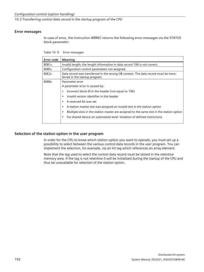
Configuration control (option handling) 10.3 Transferring control data record in the startup program of the CPU
Distributed I/O system
192 System Manual, 05/2021, A5E03576849-AK
Error messages In case of error, the instruction WRREC returns the following error messages via the STATUS block parameter:
Table 10- 9 Error messages
Error code Meaning 80B1H Invalid length; the length information in data record 196 is not correct. 80B5H Configuration control parameters not assigned. 80E2H Data record was transferred in the wrong OB context. The data record must be trans-
ferred in the startup program. 80B8H Parameter error
A parameter error is caused by: • Incorrect block ID in the header (not equal to 196) • Invalid version identifier in the header • A reserved bit was set • A station master slot was assigned an invalid slot in the station option • Multiple slots in the station master are assigned to the same slot in the station option • For shared device on submodule level: Violation of defined restrictions
Selection of the station option in the user program In order for the CPU to know which station option you want to operate, you must set up a possibility to select between the various control data records in the user program. You can implement the selection, for example, via an Int tag which references an array element.
Note that the tag used to select the control data record must be stored in the retentive memory area. If the tag is not retentive it will be initialized during the startup of the CPU and thus be unavailable for selection of the station option.

Configuration control (option handling) 10.3 Transferring control data record in the startup program of the CPU
Distributed I/O system
System Manual, 05/2021, A5E03576849-AK 193
Special aspects relating to the transfer of the control data record to the CPU • If you have enabled configuration control, the CPU is not ready for operation without a
control data record. The CPU returns from startup to STOP if a valid control data record is not transferred in the startup OB. The central I/O is not initialized in this case. The cause for the STOP mode is entered in the diagnostics buffer.
Note
If an incorrect control data record is transferred to the CPU in the startup OB, the startup of the CPU may be prevented.
In this case, perform a reset to factory settings of the CPU and then transfer a correct control data record.
• The CPU processes the WRREC instruction for transfer of the control data record asynchronously. For this reason, you must call WRREC in the startup OB repeatedly in a loop until the output parameters "BUSY" or "DONE" indicate that the data record has been transferred.
– Tip: To program the loop, use the SCL programming language with the REPEAT ... UNTIL instruction.
REPEAT
"WRREC_DB"(REQ := "start_config_control",
ID := "Local~Configuration",
INDEX := 196,
LEN := "conf_LEN",
DONE => "conf_DONE",
BUSY => "conf_BUSY",
RECORD := "ConfDB".ConfigControl["ConfDB".Option],
//Selection of control data record
ERROR => "conf_ERROR",
STATUS => "conf_STATUS");
UNTIL NOT "conf_BUSY"
END_REPEAT;

Configuration control (option handling) 10.3 Transferring control data record in the startup program of the CPU
Distributed I/O system
194 System Manual, 05/2021, A5E03576849-AK
– In the graphical programming languages, you implement the loop using instructions for program control.
Example in FBD: Use the LABEL (jump label) and JMP (jump at RLO=1) instructions to program a loop.
Figure 10-5 WRREC
• The control data record is stored retentively in the CPU. Note:
– The retentivity of the control data record is independent of the retentivity settings in the STEP 7 memory area. This means that the memory area in which the control data record is configured does not have to be configured as retentive for this purpose.
– If you write a control data record with modified configuration, the original data record 196 is deleted and the new data record 196 is saved retentively. The CPU will then restart with the modified configuration.
– The control data record is saved retentively in the CPU, which means that it is not necessary to write the control data record 196 again at a restart if the configuration is unchanged. We recommend that a memory reset of the CPU be performed prior to commissioning to delete any control data record that may be present.

Configuration control (option handling) 10.4 Behavior during operation
Distributed I/O system
System Manual, 05/2021, A5E03576849-AK 195
Special aspects relating to the transfer of the control data record to the interface module • If you have enabled configuration control, the ET 200SP station is not ready for operation
without a control data record. As long as no valid control data record has been transferred, the I/O modules are considered as failed by the CPU and exhibit substitute value behavior. The interface module continues to exchange data.
• The control data record is stored retentively in the interface module. Note:
– If there have been no changes to the configuration, you do not need to rewrite the control data record 196 during restart.
– If you write a control data record with modified configuration to the interface module, it will result in a station failure in the distributed I/O system. The original data record 196 is deleted and the new data record 196 is saved retentively. The station will then restart with the modified configuration.
10.4 Behavior during operation
Effect of discrepancy between station master and station option For the online display and for the display in the diagnostics buffer (module OK or module faulty), the station master is always used and not the differing station option.
Example: A module supplies diagnostic information. This module is configured in slot 4 in the station master, but is inserted in slot 3 in the station option (missing module; see example in the next section). The online view (station master) shows a faulty module in slot 4. In the real configuration, the module in slot 3 indicates an error via an LED display.
Response when modules are missing If modules are entered as not present in the control data record, the automation system behaves as follows:
• Modules designated as not present in the control data record do not supply diagnostics and their status is always OK. The value status is OK.
• Direct write access to the outputs that are not present or write access to the process image of the outputs that are not present: Remains without effect; no access error is signaled.
• Direct read access to the inputs that are not present or read access to the process image of the inputs that are not present: Value "0" is supplied; no access error is signaled.
• Write data record to module that is not present: Remains without effect; no error is signaled.
• Read data record from module that is not present: An error is signaled because a valid data record cannot be returned.

Configuration control (option handling) 10.5 Examples of configuration control
Distributed I/O system
196 System Manual, 05/2021, A5E03576849-AK
Inserting modules on empty slots If you replace a BU cover placed on an empty slot with an I/O module when configuration control is enabled, the ET 200SP distributed I/O system behaves as follows:
• Interface module: When the BU cover is removed, a removal interrupt is signaled. When the I/O module is inserted, an insertion alarm (wrong module) is signaled.
• CPU: A removal/insertion interrupt is not signaled when the BU cover is removed or when the I/O module is inserted.
10.5 Examples of configuration control A station master consisting of an interface module, three I/O modules and the server module is configured in STEP 7 in the following section.
Four station options are derived from the station master with the configuration control:
• Station option 1 with module that is not present
• Station option 2 with modified order of modules
• Station option 3 with empty slot
• Station option 4: Opening a new potential group

Configuration control (option handling) 10.5 Examples of configuration control
Distributed I/O system
System Manual, 05/2021, A5E03576849-AK 197
Station option 1 with module that is not present The module that is located in slot 3 in the station master is not present in the station option 1. Slot 3 must be designated in the control data record accordingly with 0 (= not present). The server module is located in slot 3 in the station option.
Figure 10-6 Example: Hardware configuration of station option 1 with the associated control data record in STEP 7

Configuration control (option handling) 10.5 Examples of configuration control
Distributed I/O system
198 System Manual, 05/2021, A5E03576849-AK
Station option 2 with modified order of modules The order of the modules at slots 2 and 3 is interchanged.
Figure 10-7 Example: Hardware configuration of station option 2 with the associated control data
record in STEP 7

Configuration control (option handling) 10.5 Examples of configuration control
Distributed I/O system
System Manual, 05/2021, A5E03576849-AK 199
Station option 3 with empty slot The module that is located in slot 3 in the station master occupies an empty slot with BU cover in the station option. Enter the value 130 in slot 3 in the control data record.
Figure 10-8 Example: Hardware configuration of station option 3 with the associated control data record in STEP 7

Configuration control (option handling) 10.5 Examples of configuration control
Distributed I/O system
200 System Manual, 05/2021, A5E03576849-AK
Station option 4: Opening a new potential group A new potential group is opened at slot 3 of station option 4. Compared to the station master, a dark-colored BaseUnit is replaced by a light-colored BaseUnit. Enter the value 1 as additional function.
Figure 10-9 Example: Hardware configuration of station option 4 with the associated control data record in STEP 7

Distributed I/O system
System Manual, 05/2021, A5E03576849-AK 201
Commissioning 11 11.1 Overview
Introduction This section includes information on the following topics:
• Commissioning the ET 200SP distributed I/O system on the PROFINET IO
• Commissioning the ET 200SP distributed I/O system on the PROFIBUS DP
• Startup of the ET 200SP distributed I/O system with empty slots
• Removing/inserting the SIMATIC memory card
• Operating modes of the CPU
• CPU memory reset
• Reassigning parameters during operation
• Identification and maintenance data
Commissioning requirements
Note Performing tests
You must ensure the safety of your plant. You therefore need to run a complete functional test and make the necessary safety checks before the final commissioning of a plant.
Also allow for any possible foreseeable errors in the tests. This avoids endangering persons or equipment during operation.
Note Check coding element in the I/O module
Make sure that the coding element is present in the I/O module before you plug in the I/O module for the first time. This reduces the risk of plugging the wrong type of module onto a wired BaseUnit when replacing a module.
PRONETA With SIEMENS PRONETA (PROFINET network analysis), you analyze the system network during commissioning. PRONETA features two core functions:
• The topology overview independently scans PROFINET and all connected components.
• The IO check is a fast test of the wiring and the module configuration of a system.
You can find SIEMENS PRONETA on the Internet (https://support.automation.siemens.com/WW/view/en/67460624).

Commissioning 11.1 Overview
Distributed I/O system
202 System Manual, 05/2021, A5E03576849-AK
MultiFieldbus Configuration Tool (MFCT) You use the MultiFieldbus Configuration Tool (MFCT) to configure and parameterize MultiFieldbus devices (e.g. IM 155-6 MF HF). You download the configuration and parameterization to the MF device with MFCT.
You can also use the MFCT to update the firmware of MF devices and modules.
You can find MFCT on the Internet (https://support.industry.siemens.com/cs/ww/en/view/109773881).
SIMATIC Automation Tool You can use the SIMATIC Automation Tool to perform commissioning and maintenance activities simultaneously on various SIMATIC S7 stations as a bulk operation independent of the TIA Portal.
General function overview:
• Network browsing and creation of a table showing the accessible devices in the network.
• Flashing of device LEDs or HMI display to locate a device
• Loading addresses (IP, subnet, gateway) into a device
• Loading the PROFINET name (station name) into a device name
• Placing a CPU in RUN or STOP mode
• Setting the time in a CPU to the current time of your programming device/PC
• Downloading a new program to a CPU or an HMI device
• Downloading from CPU, downloading to CPU or deleting recipe data from a CPU
• Downloading from CPU or deleting data log data from a CPU
• Backup/restore of data from/to a backup file for CPUs and HMI devices
• Downloading service data from a CPU
• Reading the diagnostics buffer of a CPU
• General reset of a CPU's memory
• Resetting devices to factory settings
• Downloading a firmware update to a device
You can find the SIMATIC Automation Tool on the Internet (https://support.industry.siemens.com/cs/ww/de/view/98161300).

Commissioning 11.2 Commissioning the ET 200SP for PROFINET IO
Distributed I/O system
System Manual, 05/2021, A5E03576849-AK 203
11.2 Commissioning the ET 200SP for PROFINET IO
Requirements • The CPU/interface module is in the "Factory settings" status or has been reset to factory
settings (see section Interface module (https://support.automation.siemens.com/WW/view/en/55683316/133300)).
• For CPU: The SIMATIC memory card is as delivered or has been formatted.
11.2.1 ET 200SP CPU as an IO controller
Configuration example To use the ET 200SP distributed I/O system as an IO controller, you require the CPU 151xSP-1 PN.
Figure 11-1 ET 200SP CPU as an IO controller

Commissioning 11.2 Commissioning the ET 200SP for PROFINET IO
Distributed I/O system
204 System Manual, 05/2021, A5E03576849-AK
Commissioning procedure To commission the ET 200SP distributed I/O system CPU as an IO controller for PROFINET IO, we recommend the following procedure:
Table 11- 1 Procedure for commissioning the ET 200SP CPU as an IO controller for PROFINET IO
Step
Procedure See ...
1 Installing ET 200SP Section Installation (Page 68) 2 Connecting ET 200SP
• Supply voltages • PROFINET IO • Sensors and actuators
Section Wiring (Page 90)
3 Inserting a SIMATIC memory card in the IO controller
Section Removing/inserting a SIMATIC memory card on the CPU (Page 213)
4 Configuring the IO controller1 Section Configuring (Page 137) 5 Checking the protective measures - 6 Switching on supply voltages for the
IO controller CPU 15xxSP-1 PN (https://support.automation.siemens.com/WW/view/en/90466439/133300) manual
7 Switching on supply voltages for IO devic-es
Documentation of the IO device
8 Downloading the configuration to the IO controller
STEP 7 online help
9 Switching IO controller to RUN mode CPU 15xxSP-1 PN (https://support.automation.siemens.com/WW/view/en/90466439/133300) manual
10 Checking LEDs CPU 15xxSP-1 PN (https://support.automation.siemens.com/WW/view/en/90466439/133300) manual
11 Testing inputs and outputs The following functions are helpful: Monitoring and modifying tags, testing with program status, forc-ing, controlling the outputs. See section Test and service functions (Page 264)
1 The IO devices are configured with the IO controller.

Commissioning 11.2 Commissioning the ET 200SP for PROFINET IO
Distributed I/O system
System Manual, 05/2021, A5E03576849-AK 205
11.2.2 ET 200SP CPU as an I-device
Configuration example You need the CPU 151xSP-1 PN to use the ET 200SP distributed I/O system as an I-device.
Figure 11-2 ET 200SP CPU as an I-device

Commissioning 11.2 Commissioning the ET 200SP for PROFINET IO
Distributed I/O system
206 System Manual, 05/2021, A5E03576849-AK
Commissioning procedure For commissioning of the ET 200SP distributed I/O system as an I-device on the PROFINET IO, we recommend the following procedure:
Table 11- 2 Procedure for commissioning the ET 200SP as an I-device on the PROFINET IO
Step Procedure See ... 1 Installing ET 200SP Section Installation (Page 68) 2 Connecting ET 200SP
• Supply voltages • PROFINET IO • Sensors and actuators
Section Wiring (Page 90)
3 Inserting a SIMATIC memory card in the I-device
Section Removing/inserting a SIMATIC memory card on the CPU (Page 213)
4 Configuring the I-device Section Configuring (Page 137) 5 Checking the protective measures - 6 Switching on supply voltages for the
IO controller Documentation of the IO controller
7 Switching on supply voltages for I-device and IO devices
CPU 15xxSP-1 PN (https://support.automation.siemens.com/WW/view/en/90466439/133300) manual and documentation of the IO devices
8 Download configuration to the I-device STEP 7 online help 9 Switching IO controller and I-device to RUN
mode Documentation of the IO controller and CPU 15xxSP-1 PN (https://support.automation.siemens.com/WW/view/en/90466439/133300) manual
10 Checking LEDs CPU 15xxSP-1 PN (https://support.automation.siemens.com/WW/view/en/90466439/133300) manual
11 Testing inputs and outputs The following functions are helpful: Mon-itoring and modifying tags, testing with program status, forcing, controlling the outputs. See section Test and service functions (Page 264)

Commissioning 11.2 Commissioning the ET 200SP for PROFINET IO
Distributed I/O system
System Manual, 05/2021, A5E03576849-AK 207
11.2.3 ET 200SP as an IO device
Configuration example To use the ET 200SP distributed I/O system as an IO device, you need the IM 155-6 PNxx interface module.
Figure 11-3 ET 200SP as an IO device
Commissioning procedure For commissioning of the ET 200SP distributed I/O system as an IO device on the PROFINET IO, we recommend the following procedure:
Table 11- 3 Procedure for commissioning the ET 200SP as an IO device for PROFINET IO
Step Procedure See ... 1 Installing ET 200SP Section Installation (Page 68) 2 Connecting ET 200SP
• Supply voltages • PROFINET IO • Sensors and actuators
Section Wiring (Page 90)
4 Configuring IO controller Documentation of the IO controller 5 Checking the protective measures - 6 Switching on supply voltages for the
IO controller Documentation of the IO controller
7 Switching on supply voltages for IO devices
Interface module (https://support.automation.siemens.com/WW/view/en/55683316/133300) Manual
8 Downloading the configuration to the IO controller
STEP 7 online help
9 Switching IO controller to RUN mode Documentation of the IO controller

Commissioning 11.3 Commissioning the ET 200SP on PROFIBUS DP
Distributed I/O system
208 System Manual, 05/2021, A5E03576849-AK
Step Procedure See ... 10 Checking LEDs Interface module
(https://support.automation.siemens.com/WW/view/en/55683316/133300) Manual
11 Testing inputs and outputs The following functions are helpful: Moni-toring and modifying tags, testing with program status, forcing, controlling the outputs. Refer to section Test and service functions (Page 264)
11.3 Commissioning the ET 200SP on PROFIBUS DP
Requirements • The CPU/interface module is in the "Factory settings" status or has been reset to factory
settings (see section Interface module (https://support.automation.siemens.com/WW/view/en/55683316/133300)).
• For CPU: The SIMATIC memory card is as delivered or has been formatted.
11.3.1 ET 200SP as a DP master
Configuration example To use the ET 200SP distributed I/O system as a DP master, you need the CPU 151xSP-1 PN and the CM DP communication module.
Figure 11-4 ET 200SP as a DP master

Commissioning 11.3 Commissioning the ET 200SP on PROFIBUS DP
Distributed I/O system
System Manual, 05/2021, A5E03576849-AK 209
Commissioning procedure To commission the ET 200SP distributed I/O system as a DP master on PROFIBUS DP, we recommend the following procedure:
Table 11- 4 Procedure for commissioning the ET 200SP as a DP master on the PROFIBUS DP
Step Procedure See ... 1 Installing ET 200SP (with CPU and CM DP) Section Installation (Page 68) 2 Connecting ET 200SP
• Supply voltages • PROFIBUS DP • Sensors and actuators
Section Wiring (Page 90)
3 Inserting a SIMATIC memory card in the DP master (CPU)
Section Removing/inserting a SIMATIC memory card on the CPU (Page 213)
4 Configuring DP master (including PROFIBUS address)
CPU 15xxSP-1 PN (https://support.automation.siemens.com/WW/view/en/90466439/133300) and CM DP manual
5 Switching on supply voltages for DP master CPU 15xxSP-1 PN (https://support.automation.siemens.com/WW/view/en/90466439/133300) manual
6 Switching on supply voltages for DP slaves Documentation of the DP slave 7 Download configuration to the DP master STEP 7 online help 8 Switching DP master to RUN CPU 15xxSP-1 PN
(https://support.automation.siemens.com/WW/view/en/90466439/133300) manual
9 Checking LEDs CPU 15xxSP-1 PN (https://support.automation.siemens.com/WW/view/en/90466439/133300) manual
10 Testing inputs and outputs The following functions are helpful: Mon-itoring and modifying tags, testing with program status, forcing, controlling the outputs. See section Test and service functions (Page 264)

Commissioning 11.3 Commissioning the ET 200SP on PROFIBUS DP
Distributed I/O system
210 System Manual, 05/2021, A5E03576849-AK
11.3.2 ET 200SP as I-slave
Configuration example To use the ET 200SP distributed I/O system as I-slave, you need the CPU 151xSP-1 PN and the CM DP communication module.
Figure 11-5 ET 200SP as I-slave

Commissioning 11.3 Commissioning the ET 200SP on PROFIBUS DP
Distributed I/O system
System Manual, 05/2021, A5E03576849-AK 211
Commissioning procedure For commissioning of the ET 200SP distributed I/O system as an I-slave on the PROFIBUS DP, we recommend the following procedure:
Table 11- 5 Procedure for commissioning the ET 200SP as an I-slave for PROFIBUS DP
Step Procedure See ... 1 Installing ET 200SP (with CPU and CM DP) Section Installation (Page 68) 2 Connecting ET 200SP
• Supply voltages • PROFIBUS DP • Sensors and actuators
Section Wiring (Page 90)
3 Configuring DP master (including PROFIBUS ad-dress)
Documentation of the DP master
4 Inserting a SIMATIC memory card in the I-slave (CPU)
Section Removing/inserting a SIMATIC memory card on the CPU (Page 213)
5 Configuring I-slave (including PROFIBUS address) CPU 15xxSP-1 PN (https://support.automation.siemens.com/WW/view/en/90466439/133300) and CM DP manual
6 Switching on supply voltages for DP master Documentation of the DP master 7 Switching on supply voltages for I-slaves CPU 15xxSP-1 PN
(https://support.automation.siemens.com/WW/view/en/90466439/133300) manual
8 Loading configuration in the DP master and I-slaves
STEP 7 online help
9 Switching DP master and I-slaves to RUN Documentation of the DP master and CPU 15xxSP-1 PN (https://support.automation.siemens.com/WW/view/en/90466439/133300) manual
10 Checking LEDs CPU 15xxSP-1 PN (https://support.automation.siemens.com/WW/view/en/90466439/133300) manual
11 Testing inputs and outputs The following functions are helpful: Monitoring and modifying tags, testing with program status, forc-ing, controlling the outputs. See the Test functions and fault resolu-tion (https://support.automation.siemens.com/WW/view/en/90466439/133300) section

Commissioning 11.3 Commissioning the ET 200SP on PROFIBUS DP
Distributed I/O system
212 System Manual, 05/2021, A5E03576849-AK
11.3.3 ET 200SP as a DP slave
Configuration example To use the ET 200SP distributed I/O system as a DP slave, you need the IM 155-6 DP HF.
Figure 11-6 ET 200SP as a DP slave
Commissioning procedure To commission the ET 200SP distributed I/O system as a DP slave on PROFIBUS DP, we recommend the following procedure:
Table 11- 6 Procedure for commissioning the ET 200SP as a DP master for PROFIBUS DP
Step Procedure See ... 1 Installing ET 200SP (with IM 155-6 DP HF) Section Installation (Page 68) 2 Setting the PROFIBUS address on the
interface module Section Interface module (http://support.automation.siemens.com/WW/view/en/55683316/133300)
3 Connecting ET 200SP • Supply voltages • PROFIBUS DP • Sensors and actuators
Section Wiring (Page 90)
4 Configuring DP master (including PROFIBUS address)
Documentation of the DP master
5 Switching on supply voltages for DP mas-ter
Documentation of the DP master
6 Switching on supply voltages for DP slaves
Interface module (http://support.automation.siemens.com/WW/view/en/55683316/133300) Manual
7 Download configuration to the DP master STEP 7 online help 8 Switching DP master to RUN Documentation of the DP master

Commissioning 11.4 Startup of the ET 200SP with empty slots
Distributed I/O system
System Manual, 05/2021, A5E03576849-AK 213
Step Procedure See ... 9 Checking LEDs Interface module
(http://support.automation.siemens.com/WW/view/en/55683316/133300) Manual
10 Testing inputs and outputs The following functions are helpful: Moni-toring and modifying tags, testing with program status, forcing, controlling the outputs. Refer to section Test and service functions (Page 264)
11.4 Startup of the ET 200SP with empty slots
Procedure You can configure the ET 200SP distributed I/O system with any number of empty slots.
To build the ET 200SP distributed I/O system with any number of empty slots, follow these steps:
1. Cover all empty slots with BU covers.
2. Finish the configuration with a server module.
Special consideration: A "Module missing in slot x" diagnostic message is generated by the CPU/interface module for empty slots in which I/O modules are configured.
11.5 Removing/inserting a SIMATIC memory card on the CPU
Requirement The CPU only supports pre-formatted SIMATIC memory cards. If necessary, delete all previously stored data before using the SIMATIC memory card. You can find more information on deleting the content of the SIMATIC memory card in the function manual Structure and use of the CPU memory.
In order to work with the SIMATIC memory card, first ensure that the SIMATIC memory card is not write-protected. If it is, move the slider out of the lock position.

Commissioning 11.5 Removing/inserting a SIMATIC memory card on the CPU
Distributed I/O system
214 System Manual, 05/2021, A5E03576849-AK
Inserting the SIMATIC memory card To insert a SIMATIC memory card, follow these steps:
1. Ensure that the CPU is either switched off or in STOP mode.
2. Insert the SIMATIC memory card, as depicted on the CPU, into the slot for the SIMATIC memory card.
Figure 11-7 Slot for the SIMATIC memory card
3. Insert the SIMATIC memory card with light pressure into the CPU, until the SIMATIC memory card latches.
Removal of the SIMATIC memory card To remove a SIMATIC memory card, follow these steps:
1. Switch the CPU to STOP mode.
2. Press the SIMATIC memory card into the CPU with light pressure. After audible unlatching of the SIMATIC memory card, remove it.
Only remove the SIMATIC memory card in POWER OFF or STOP mode of the CPU. Ensure that no writing functions (online functions with the programming device, e.g. loading/deleting a block, test functions) are active in STOP mode or were active before POWER OFF.
Reactions after removing/inserting the SIMATIC memory card Inserting and removing the SIMATIC memory card in STOP, STARTUP or RUN mode triggers a re-evaluation of the SIMATIC memory card. The CPU hereby compares the content of the configuration on the SIMATIC memory card with the backed-up retentive data. If the backed-up retentive data matches the data of the configuration on the SIMATIC memory card, the retentive data is retained. If the data differs, the CPU automatically performs a memory reset (which means the retentive data is deleted) and then goes to STOP.
The CPU evaluates the SIMATIC memory card, and this is indicated by the RUN/STOP LED flashing.
Reference You can find more information on the SIMATIC memory card in the function manual Structure and use of the CPU memory (https://support.industry.siemens.com/cs/ww/en/view/59193101).

Commissioning 11.6 Operating modes of the CPU
Distributed I/O system
System Manual, 05/2021, A5E03576849-AK 215
11.6 Operating modes of the CPU
Introduction Operating modes describe the status of the CPU. The following operating modes are possible using the mode selector:
• STARTUP
• RUN
• STOP
In these operating modes, the CPU can communicate, for example, via the PROFINET interface.
The status LEDs on the front of the CPU indicate the current operating mode.
11.6.1 STARTUP mode
Behavior Before the CPU starts to execute the cyclic user program, a startup program is executed.
By suitably programming startup OBs, you can specify initialization tags for your cyclic program in the startup program. You have the option of programming no, one or several startup OBs.
Special features during startup Note the following points regarding the STARTUP mode:
• All outputs are disabled or react according to the parameter settings for the particular I/O module: They provide a substitute value as set in the parameters or retain the last value output and bring the controlled process to a safe operational status.
• The process image is initialized.
• The process image is not updated.
In order to read the current state of inputs during STARTUP, you can access inputs via direct I/O access.

Commissioning 11.6 Operating modes of the CPU
Distributed I/O system
216 System Manual, 05/2021, A5E03576849-AK
To initialize outputs during STARTUP, values can be written via the process image or via direct I/O access. The values are output to the outputs during the transition to RUN mode.
• The CPU always starts up in warm restart mode.
– The non-retentive bit memory, timers and counters are initialized.
– The non-retentive tags in data blocks are initialized.
• During startup, cycle time monitoring is not yet running
• The CPU processes the startup OBs in the order of the startup OB numbers. The CPU processes all programmed startup OBs regardless of the selected startup mode. (Figure "Setting the startup behavior").
• If a corresponding event occurs, the CPU can start the following OBs during startup:
– OB 82: Diagnostics interrupt
– OB 83: Pull/plug interrupt for modules
– OB 86: Rack error
– OB 121: Programming error (only for global error handling)
– OB 122: I/O access error (only for global error handling)
You can find a description of how to use global and local error handling in the STEP 7 online help.
The CPU does not start all other OBs until the transition to RUN mode.
Response when expected and actual configurations do not match The configuration downloaded to the CPU represents the expected configuration. The actual configuration is the actual configuration of the ET 200SP distributed I/O system. If the expected configuration and actual configuration do not match, the setting of the "Comparison preset to actual configuration" parameter determines the behavior of the CPU. You can find additional information on hardware compatibility in the section Operating mode transitions (Page 219).
Cancellation of startup If errors occur during startup, the CPU cancels startup and returns to STOP mode.
The CPU does not perform the startup or interrupts the startup under the following conditions:
• You have not inserted a SIMATIC memory card or have inserted an invalid one.
• You have not downloaded a hardware configuration to the CPU.
Configuring the startup behavior You configure the behavior of the CPU in the Startup group in the CPU properties.

Commissioning 11.6 Operating modes of the CPU
Distributed I/O system
System Manual, 05/2021, A5E03576849-AK 217
Setting the startup behavior To set the startup behavior, follow these steps:
1. Select the CPU in the device view of the STEP 7 hardware network editor.
2. In the properties under "General" select the "Startup" area.
Figure 11-8 Setting the startup behavior
① Sets the startup type after POWER ON ② Defines the startup behavior when a module in a slot does not correspond to the config-
ured module. You can set this parameter centrally, on the CPU or for each module. When you change the setting for a module, the setting made centrally for this module no longer applies. • Startup CPU only if compatible: In this setting a module on a configured slot has to be
compatible with the configured module. Compatible means that the module matches in terms of the number of inputs and outputs and with respect to its electrical and functional properties.
• Startup CPU even if mismatch: With this setting the CPU starts up regardless of the type of module plugged in.
③ Specifies a maximum period (default: 60000 ms) in which the I/O must be ready for oper-ation. The CPU changes to RUN. If the central and distributed I/O is not ready for operation within the configuration time, the startup characteristics of the CPU depends on the setting of the "Comparison preset to actual configuration" parameter.

Commissioning 11.6 Operating modes of the CPU
Distributed I/O system
218 System Manual, 05/2021, A5E03576849-AK
Example for the "Comparison preset to actual configuration" parameter "Startup CPU only if compatible":
The DI 16x24VDC ST input module with 16 digital inputs is a compatible replacement for a DI 8x24VDC ST input module with 8 digital inputs. The pin assignment and all electrical and functional properties are identical.
"Startup CPU even if mismatch":
Instead of a configured digital input module, you insert an analog output module or no module is present in this slot and thus in all subsequent slots. Although the configured inputs cannot be accessed, the CPU starts up.
Note that the user program cannot function correctly in this case and take the appropriate measures.
11.6.2 STOP mode
Behavior The CPU does not execute the user program in STOP mode.
All outputs are disabled or react according to the parameter settings for the particular I/O module: They provide a substitute value as set in the parameters or retain the last value output keeping the controlled process in a safe operating status.
In STOP mode, the motor starter responds according to how it was parameterized for the CPU STOP state. The CPU STOP state can be circumvented with the manual local control (Local Control) function. If the CPU is switched off, a motor can be switched on in the motor starter's commissioning mode.
You will find additional information in the Motor starter (https://support.industry.siemens.com/cs/ww/en/view/109479973) manual.
11.6.3 RUN mode
Behavior In "RUN" mode the cyclic, time-driven, and interrupt-driven program is executed. Addresses that are in the "Automatic Update" process image are automatically updated in each program cycle. See also the section Process images and process image partitions (Page 145).

Commissioning 11.6 Operating modes of the CPU
Distributed I/O system
System Manual, 05/2021, A5E03576849-AK 219
Execution of the user program Once the CPU has read the inputs, the cyclic program is executed from the first instruction to the last instruction.
If you have configured a minimum cycle time, the CPU will not end the cycle until this minimum cycle time is finished even if the user program is completed sooner.
A cycle monitoring time is set to ensure that the cyclic program is completed within a specified time. You can change the cycle monitoring time to suit your requirements. If the cyclic program has not finished running within this time, the system responds with a time error. Further events such as hardware interrupts and diagnostics interrupts can interrupt the cyclic program flow and prolong the cycle time.
Reference Further information about cycle and response times is available in the Function Manual Cycle and response times (https://support.automation.siemens.com/WW/view/en/59193558).
11.6.4 Operating mode transitions
Operating modes and operating mode transitions The following figure shows the operating modes and the operating mode transitions:
Figure 11-9 Operating modes and operating mode transitions

Commissioning 11.6 Operating modes of the CPU
Distributed I/O system
220 System Manual, 05/2021, A5E03576849-AK
The table below shows the effects of the operating mode transitions:
Table 11- 7 Operating mode transitions
No. Operating mode transitions Effects ① POWER ON →
STARTUP After switching on, the CPU switches to "STARTUP" mode if: • The hardware configuration and program blocks are
consistent. • Startup type "Warm restart - RUN" is set.
Or • Startup type "Warm restart - mode before POWER
OFF" is set and the CPU was in RUN mode before POWER OFF.
The CPU clears the non-retentive memory, and resets the content of non-retentive DBs to the start values of the load memory. Reten-tive memory and retentive DB contents are retained. The 500 newest entries in the diagnostics buffer are retained.
② POWER ON → STOP After switching on, the CPU goes to "STOP" mode if: • The hardware configuration and program blocks are
inconsistent.
Or • The "No restart" startup type is set.
Or • Startup type "Warm restart - mode before POWER
OFF" is set and the CPU was in STOP mode before POWER OFF.
The CPU clears the non-retentive memory, and resets the content of non-retentive DBs to the start values of the load memory. Reten-tive memory and retentive DB contents are retained. The 500 newest entries in the diagnostics buffer are retained.
③ STOP → STARTUP The CPU switches to "STARTUP" mode if: • The hardware configuration and program blocks are
consistent. • You set the CPU to "RUN" mode via the program-
ming device and the mode switch in is RUN position.
Or • You set the mode switch from STOP to RUN.
The CPU clears the non-retentive memory, and resets the content of non-retentive DBs to the start values of the load memory. Reten-tive memory and retentive DB contents are retained. The 500 newest entries in the diagnostics buffer are retained.
④ STARTUP → STOP In the following cases, the CPU goes from "STARTUP" to "STOP" mode when: • The CPU detects an error during startup. • You set the CPU to "STOP" via the programming
device or mode switch. • The CPU executes a STOP command in the Startup
OB.
These operating mode transitions have no effect on data.

Commissioning 11.7 CPU memory reset
Distributed I/O system
System Manual, 05/2021, A5E03576849-AK 221
No. Operating mode transitions Effects ⑤ STARTUP → RUN In the following cases, the CPU goes from "STARTUP" to
"RUN" mode when: • The CPU has initialized the PLC tags. • The CPU has executed the startup blocks successful-
ly.
⑥ RUN → STOP In the following cases, the CPU goes from "RUN" back to "STOP" mode when: • The CPU detects an error which prevents further
work. • The CPU executes a STOP command in the user
program. • You set the CPU to "STOP" via the programming
device or mode switch.
11.7 CPU memory reset
Basics of a memory reset The CPU must be in STOP mode for a memory reset.
A memory reset returns the CPU to its "initial state".
Memory reset means:
• An existing online connection between your programming device/PC and the CPU is terminated.
• The content of the work memory and the retentive and non-retentive data (applies only to manual memory reset by the user) are deleted.
• The diagnostics buffer, time of day, IP address and the device name are retained.
• Subsequently the CPU is initialized with the loaded project data (hardware configuration, code and data blocks, force jobs). The CPU copies this data from the load memory to the work memory.
Result:
– If you set an IP address in the hardware configuration ("Set IP address in the project" option) and a SIMATIC memory card with the project is in the CPU, this IP address is valid after the memory reset.
– Data blocks no longer have current values but rather their configured start values.
– Force jobs remain active.
Detecting a CPU memory reset The RUN/STOP LED flashes yellow at 2 Hz. After completion, the CPU switches to STOP. The RUN/STOP LED is on (constant yellow light).

Commissioning 11.7 CPU memory reset
Distributed I/O system
222 System Manual, 05/2021, A5E03576849-AK
Result after memory reset The following table provides an overview of the contents of the memory objects after memory reset.
Table 11- 8 Memory objects after memory reset
Memory object Content Actual values of the data blocks, instance data blocks Initialized Bit memory, timers and counters Initialized Retentive tags from technology objects (for example, adjustment values of absolute encoders)*
Retained
Diagnostics buffer entries Retained IP address Retained Device name Retained Counter readings of the runtime meters Retained Time of day Retained * The retentive tags from technology objects are retained but the content of certain tags is re-
initialized in some cases.
Note Password for protection of confidential configuration data
The password for protection of confidential configuration data is retained after a memory reset of the CPU. The password is only deleted when the "Delete password for protection of confidential PLC configuration data" option is set.
You can find additional information on the password for protection of confidential configuration data in the Communication (https://support.industry.siemens.com/cs/ww/en/view/59192925) function manual.
11.7.1 Automatic memory reset
Possible causes of automatic memory reset The CPU executes an automatic memory reset if an error occurs that prevents normal further processing.
Causes of such errors are:
• User program is too large, and cannot be completely loaded into work memory.
• The project data on the SIMATIC memory card is corrupt, for example, because a file was deleted.
• If you remove or insert the SIMATIC memory card and the backed-up retentive data differs in structure from that of the configuration on the SIMATIC memory card.

Commissioning 11.7 CPU memory reset
Distributed I/O system
System Manual, 05/2021, A5E03576849-AK 223
11.7.2 Manual memory reset
Reason for a manual memory reset CPU memory reset is required to reset the CPU to its "original state".
CPU memory reset Two options are available for performing a CPU memory reset:
• Using the mode selector
• Using STEP 7
Procedure using the mode selector
Note Memory reset ↔ Reset to factory settings
The procedure described below also corresponds to the procedure for resetting to factory settings: • Selector operation with inserted SIMATIC memory card: CPU executes a memory reset • Selector operation without inserted SIMATIC memory card: CPU executes reset to factory
settings
To reset the CPU memory using the mode selector, proceed as follows:
1. Set the mode selector to the STOP position.
Result: The RUN/STOP LED lights up yellow.
2. Set the mode selector to the MRES position. Hold the selector in this position until the RUN/STOP LED lights up for the 2nd time and remains continuously lit (this takes three seconds). After this, release the switch.
3. Within the next three seconds, switch the mode selector back to the MRES position, and then back to STOP again.
Result: The CPU executes memory reset.
For information on resetting the CPU to factory settings, refer to the section Resetting the CPU to factory settings (Page 255).
Procedure using STEP 7 For a memory reset of the CPU using STEP 7 proceed as follows:
1. Open the "Online Tools" task card of the CPU.
2. Click the "MRES" button in the "CPU control panel" pane.
3. Click "OK" in response to the confirmation prompt.
Result: The CPU switches to STOP mode and performs a memory reset.

Commissioning 11.8 Reassigning parameters during operation
Distributed I/O system
224 System Manual, 05/2021, A5E03576849-AK
11.8 Reassigning parameters during operation
Introduction You have the option of reassigning the parameters for the ET 200SP I/O modules during operation.
Changing parameters during operation You make the parameter settings of the I/O modules using data records. Each I/O module has a separate data record. The instruction "WRREC" applies the changed parameters to the I/O module. The parameters that you have set with STEP 7 are not changed. After a POWER OFF/POWER ON of the ET 200SP, the parameters set with STEP 7 are valid again.
If you are using the CPU as an I-device, you reassign the parameters of the I/O modules via the I-device.
Note
If you write data records from the user program to the modules of the distributed I/O, make sure that these modules actually exist and are available. You can evaluate OB83 for this purpose. After inserting a module, the CPU does not call OB83 until the module has started up and its parameters are assigned. This ensures the execution of the data record operations without errors.
Note
You need to transfer the new parameters with the "WRREC" instruction after a POWER OFF/POWER ON of the ET 200SP.
Instruction for parameter assignment The following instruction is provided for assigning parameters to the I/O module in the user program: Instruction Application "WRREC" Transfer the modifiable parameters to the addressed ET 200SP module.
Error message In the event of an error, the following return values are reported:
Table 11- 9 Error message
Error code Meaning 80E0H Error in header information 80E1H Parameter error
Reference You will find the setup of the parameter data record in the manuals of the I/O modules (https://support.automation.siemens.com/WW/view/es/55679691/133300).

Commissioning 11.9 Backing up and restoring the CPU configuration
Distributed I/O system
System Manual, 05/2021, A5E03576849-AK 225
11.9 Backing up and restoring the CPU configuration
11.9.1 Overview
Backup from online device
You make changes where necessary in the system operation. You add new devices, replace existing devices or adapt the user program. If these changes result in undesirable behavior, you can restore the plant to an earlier state. Before you load a changed configuration to the CPU, first use the option "Backup from online device" to create a complete backup of the current device status. If you have assigned a password to protect confidential PLC configuration data, then this password is not secured. For more information on the password, refer to the section Protection of confidential configuration data (Page 165).
Upload from device (software)
With the option "Upload from device (software)", you load the software project data from the CPU to an existing CPU in the project.
Upload device as new station
If you are operating a new PG/PC on a system, the STEP 7 project that was used to create the system configuration might not be available. In this case, you upload the data to a project in your PG/PC with the "Upload device as new station" option.
Snapshot of the monitor values
To allow you to restore the actual values after changes, back up the actual values of the data blocks with the "Snapshot of the monitor values" option.
Overview of backup types The table below shows the backup of CPU data depending on the selected type of backup and its specific characteristics:
Backup from
online device Upload from de-vice (software)
Upload device as new station
Snapshot of the monitor values
Current values of all DBs (global and instance data blocks) 1)
Blocks of the type OB, FC, FB and DB
--
PLC tags (tag names and constant names)
--
Technology objects 3) Hardware configuration -- -- Actual values (bit memories, tim-ers, counters)*
-- -- --
Contents of the SIMATIC memory card
-- -- --
Archives, recipes -- -- --

Commissioning 11.9 Backing up and restoring the CPU configuration
Distributed I/O system
226 System Manual, 05/2021, A5E03576849-AK
Backup from online device
Upload from de-vice (software)
Upload device as new station
Snapshot of the monitor values
Entries in the diagnostics buffer -- -- -- -- Current time -- -- -- --
Properties of the type of backup Backup possible for fail-safe CPUs 2) -- Backup can be edited -- Backup possible in operating mode STOP RUN, STOP RUN, STOP RUN, STOP 1) Only the values of the tags that are set as retentive are saved.
2) Only possible in the STOP operating state and for individual fail-safe blocks. 3) Nur die High_Speed_Counter and SSI_Absolute_Encoder modules
Reference You can find more information on the different backup types in the STEP 7 online help.
Emergency address (emergency IP) The emergency address (emergency IP address) of a CPU was conceived for diagnostic and downloading functions, e.g. if the CPU can no longer be reached via the IP protocol due to loading of an incorrect project. You can find information on the emergency address in the Communication (https://support.industry.siemens.com/cs/ww/de/view/59192925/en) function manual.
Archiving multilingual project texts When you configure a CPU, different categories of texts come into being, e.g.
• Object names (names of blocks, modules, tags, etc.)
• Comments (for blocks, networks, watch tables, etc.)
• Messages and diagnostic texts
Texts are provided by the system (e.g. diagnostic buffer texts) or are created during configuration (e.g. messages).
In a project, texts exist in one single language or in several languages after a translation process. You can maintain project texts in all languages, which are at your disposal in the project navigator (Languages & Resources > Project Texts). The texts arising during configuration can be loaded into the CPU.
The following texts containing the project data are loaded into the CPU in the chosen languages and are also used by the Web server:
• Diagnostic buffer texts (not editable)
• Module status texts (not editable)
• Message texts with associated text lists
• Tag comments and step comments for S7 GRAPH and PLC Code Viewer
• Comments in watch tables

Commissioning 11.9 Backing up and restoring the CPU configuration
Distributed I/O system
System Manual, 05/2021, A5E03576849-AK 227
The following texts containing the project languages are also loaded into the CPU in the chosen languages, but are not used by the Web server:
• Comments in tag tables (for tags and constants)
• Comments in global data blocks
• Comments of elements in block interfaces of FBs, FCs, DBs and UDTs
• Network titles in data blocks that are written in ladder logic (LAD), function block diagram (FBD) or statement list (STL)
• Block comments
• Network comments
• Comments of LAD and FBD elements
The CPUs support archiving of multilingual project texts in up to three different project languages. If the project texts for a particular project language nevertheless exceed the memory space reserved for them, the project cannot be downloaded to the CPU. The download is canceled with a notice that insufficient memory space is available. In such a case, take measures to reduce the required storage space, for example by shortening comments.
Note Size of the SIMATIC memory card
If, when loading projects, the required memory space is more extensive/larger than the memory space on the
SIMATIC memory card used, the download to the CPU is canceled. You receive an error message.
Therefore, make sure that there is enough available storage space on your SIMATIC memory card for loading projects.
You will find information on reading out the storage space capacity utilization of the CPU and the SIMATIC memory card in the Structure and use of the CPU memory (https://support.industry.siemens.com/cs/de/de/view/59193101/en) function manual.
You will find information on parameterization of multilingual project texts in STEP 7 in the STEP 7 online help.

Commissioning 11.10 Time synchronization
Distributed I/O system
228 System Manual, 05/2021, A5E03576849-AK
11.10 Time synchronization
Introduction All CPUs are equipped with an internal clock. The clock shows:
• The time of day with a resolution of 1 millisecond
• The date and the day of the week
The CPU takes into account the time change caused by daylight saving time.
You can synchronize the time of the CPUs with an NTP server in NTP mode (NTP: Network Time Protocol).
Operating principle In NTP mode, the device sends time queries at regular intervals (in client mode) to the NTP server in the subnet (LAN). Based on the replies of the servers, the most reliable and most accurate time is calculated and the time of day of the CPU is synchronized. The advantage of this mode is that it allows the time to be synchronized across subnets. You can synchronize the time of day of up to a maximum of four NTP servers. You address a communications processor or an HMI device, for example, as sources for time synchronization via the IP addresses.
The update interval defines the interval between the time queries (in seconds). The value range of the interval is between 10 seconds and one day. In NTP mode, it is generally UTC (Universal Time Coordinated) that is transferred. UTC corresponds to GMT (Greenwich Mean Time).
NTP server for the ET 200SP CPU You can assign an ET 200SP CPU to up to 4 NTP servers.
You have the following options to reset the IP addresses of the NTP servers:
• Configure IP addresses of the NTP servers in STEP 7.
• Set IP addresses of the NTP servers with the "T_CONFIG" instruction.
• Obtain IP addresses of the NTP servers via DHCP. As of firmware version V2.9, the CPU can also obtain the NTP servers via DHCP. You can find more information on the procedure and the DHCP communication protocol in the Communication (https://support.industry.siemens.com/cs/ww/de/view/59192925/en) function manual.

Commissioning 11.10 Time synchronization
Distributed I/O system
System Manual, 05/2021, A5E03576849-AK 229
Configuring IP addresses of the NTP servers in STEP 7 To configure the IP addresses of the NTP servers in STEP 7, follow these steps:
1. Select the ET 200SP CPU in STEP 7.
2. In the properties of the CPU, navigate to "Time of day" > "Time synchronization"> "NTP mode".
3. For "Time synchronization:", select "Set NTP server in the project" from the drop-down list.
4. Enter the IP addresses of up to four NTP servers for "Server 1" to "Server 4".
5. Set the time interval of time queries for "Update interval". Set the update interval to between 10 s and 86400 s.
Setting the IP addresses of the NTP servers with the "T_CONFIG" instruction Requirements:
• You selected the option "Set NTP server directly on the device (e.g. PLC program, display)" in the "Time synchronization" drop-down list in STEP 7.
Proceed as follows to set the IP addresses of the NTP servers with the T_CONFIG instruction:
1. Enter the IP addresses of up to four NTP servers in a tag of the data type IF_CONF_NTP.
2. Interconnect the tag of data type IF_CONF_NTP at the block parameter CONF_DATA of the T_CONFIG instruction.
3. Call the T_CONFIG instruction in the user program.
Result: The addresses of the NTP servers from the T_CONFIG instruction are transferred to the CPU.
If necessary, you can change the addresses of the NTP servers several times with T_CONFIG.
Reference For additional information on time synchronization in the automation environment, refer to the following FAQ on the Internet (https://support.industry.siemens.com/cs/de/en/view/86535497).

Commissioning 11.10 Time synchronization
Distributed I/O system
230 System Manual, 05/2021, A5E03576849-AK
11.10.1 Example: Configuring and changing NTP server
Automation task You are using your own NTP server in your network with the IP address 192.168.1.15. Your own server provides you with the following advantages:
• Protection against unauthorized accesses from outside
• Every device that you synchronize with your own NTP server uses the same time.
You want to synchronize the ET 200SP CPU with this NTP server.
The following sections describe how to configure the IP address of the NTP server in STEP 7 or set it in the user program.
Configuring the IP address of the NTP server in STEP 7
Procedure
1. Select the ET 200SP CPU in STEP 7.
2. In the properties of the CPU, navigate to "Time of day" > "Time synchronization"> "NTP mode".
3. For "Time synchronization:", select "Set NTP server in the project" from the drop-down list.
4. For "Server 1:", enter the IP address of the NTP server: 192.168.1.15.
5. Download the hardware configuration to the CPU.
Result
The CPU synchronizes the time with the NTP server 192.168.1.15.
Set IP addresses of the NTP server with the "T_CONFIG" instruction Requirements:
• You selected the option "Set NTP server directly on the device (e.g. PLC program, display)" in the "Time synchronization" drop-down list in STEP 7.
To set the IP address for the NTP server, use the following block parameters of the "T_CONFIG" instruction:
• Req: A positive edge at the block parameter "Req" starts a job of the "T_CONFIG" instruction.
• Interface: Enter the HW ID of the PROFINET interface 1 of the CPU at the block parameter "Interface". In this example, the HW ID is "64".
• Conf_Data: Area in which you save the IP addresses of the NTP server. Use the data type "IF_CONF_NTP" for this purpose.

Commissioning 11.10 Time synchronization
Distributed I/O system
System Manual, 05/2021, A5E03576849-AK 231
Procedure
Proceed as follows to set the IP address of the NTP server in the user program to "192.168.1.15":
1. Create a global data block in the project tree under "Program blocks > Add new block". Name the global data block "NTP".
2. Create a tag of the data type "IF_CONF_NTP" in the global data block "NTP".
Figure 11-10 Example: Data block with IF_CONF_NTP
3. Create a "T_CONFIG" instruction in the user program.
4. Connect the "T_CONFIG" instruction as follows.
Figure 11-11 Example T_CONFIG: Changing the NTP server

Commissioning 11.11 Identification and maintenance data
Distributed I/O system
232 System Manual, 05/2021, A5E03576849-AK
5. In the user program, assign the IP address 192.168.1.15 to the data type "IF_CONF_NTP": "NTP".NTP_Server.NTP_IP[1].ADDR[1] := 192;
"NTP".NTP_Server.NTP_IP[1].ADDR[2] := 168;
"NTP".NTP_Server.NTP_IP[1].ADDR[3] := 1;
"NTP".NTP_Server.NTP_IP[1].ADDR[4] := 15;
6. Generate a positive edge for the tag "change_NTP-Server" in the user program:
"NTP"."change_NTP-Server" := true;
Result
The CPU synchronizes the time with the NTP server 192.168.1.15.
11.11 Identification and maintenance data
11.11.1 Reading out and entering I&M data
I&M data Identification and maintenance data (I&M data) is information saved on the module. The data is:
• Read-only (I-data) or
• Readable/writable (M-data)
Identification data (I&M0): Manufacturer information about the module that can only be read. Some identification data is also printed on the housing of the module, for example article number and serial number. Maintenance data (I&M1, 2, 3): Plant-dependent information, e.g. installation location. Maintenance data is created during configuration and downloaded to the module. All modules of the ET 200SP distributed I/O system support identification data (I&M0 to I&M3).
The I&M identification data supports you in the following activities:
• Checking the plant configuration
• Locating hardware changes in a plant
• Correcting errors in a plant
Modules can be clearly identified online using the I&M identification data.
STEP 7 allows you to read the identification I&M data (see STEP 7 online help).
Note
The BusAdapter and the interface module IM 155-6 PN HF support the identification data I&M0 to I&M4 (signature).

Commissioning 11.11 Identification and maintenance data
Distributed I/O system
System Manual, 05/2021, A5E03576849-AK 233
Options for reading out I&M data • Via the user program
• Via STEP 7 or HMI devices
• Via the CPU web server
Reading I&M data via the user program You have the following options to read the modules' I&M data in the user program:
• Using the RDREC instruction
The record structure for distributed modules that are accessible via PROFINET IO/PROFIBUS DP, is described in the chapter Record structure for I&M data (Page 234).
• Using the Get_IM_Data instruction
Reference The description of the instructions can be found in the STEP 7 online help.
Reading I&M data via STEP 7 Requirements: There must be an online connection to the CPU/interface module.
To read I&M data using STEP 7, follow these steps:
1. In the project tree, under "Distributed I/O" select the IO device IM 155-6 PN ST (for example).
2. Select > IO device > Online & diagnostics > Identification & Maintenance.
Entering maintenance data via STEP 7 STEP 7 assigns a default module name. You can enter the following information:
• Plant designation (I&M1)
• Location identifier (I&M1)
• Installation date (I&M2)
• Additional information (I&M3)
To enter maintenance data via STEP 7, follow these steps:
1. In the device view of the STEP 7 hardware network editor, select the interface module, for example.
2. In the properties under "General", select the "Identification & Maintenance" area and enter the data.
During the loading of the hardware configuration, the I&M data is also loaded.

Commissioning 11.11 Identification and maintenance data
Distributed I/O system
234 System Manual, 05/2021, A5E03576849-AK
Procedure for reading I&M data via the Web server The procedure is described in detail in the Web server (https://support.automation.siemens.com/WW/view/en/59193560) Function Manual.
11.11.2 Data record structure for I&M data
Reading I&M records via the user program (distributed via PROFINET IO) You directly access specific identification data using Read data record ("RDREC" instruction). You obtain the corresponding part of the identification data under the relevant data record index.
The data records are structured as follows:
Table 11- 10 Basic structure of data records with I&M identification data
Content Length (bytes) Coding (hex) Header information BlockType 2 I&M0: 0020H
I&M1: 0021H I&M2: 0022H I&M3: 0023H
BlockLength 2 I&M0: 0038H I&M1: 0038H I&M2: 0012H I&M3: 0038H
BlockVersionHigh 1 01 BlockVersionLow 1 00 Identification data Identification data (see table below)
I&M0/index AFF0H: 54 I&M1/index AFF1H: 54 I&M2/index AFF2H: 16 I&M3/index AFF3H: 54

Commissioning 11.11 Identification and maintenance data
Distributed I/O system
System Manual, 05/2021, A5E03576849-AK 235
Table 11- 11 Data record structure for I&M identification data
Identification data Access Default Explanation Identification data 0: (data record index AFF0 hex) VendorIDHigh Read (1 byte) 00H This is where the name of the manufac-
turer is stored (42D = SIEMENS AG). VendorIDLow Read (1 byte) 2 AH Order_ID Read (20 bytes) 6ES7155-6AU00-0BN0 Article number of the module (e.g. of the
interface module) IM_SERIAL_NUMBER Read (16 bytes) - Serial number (device-specific) IM_HARDWARE_REVISION Read (2 bytes) 1 Corresponding HW version IM_SOFTWARE_REVISION Read Firmware version Provides information about the firmware
version of the module • SWRevisionPrefix (1 byte) V
• IM_SWRevision_Functional_Enhancement
(1 byte) 00 - FFH
• IM_SWRevision_Bug_Fix (1 byte) 00 - FFH
• IM_SWRevision_Internal_ Change
(1 byte) 00 - FFH
IM_REVISION_COUNTER Read (2 bytes) 0000H Provides information about parameter changes on the module (not used)
IM_PROFILE_ID Read (2 bytes) 0000H Generic Device IM_PROFILE_SPECIFIC_TYPE Read (2 bytes) 0005H Interface modules/BusAdapters
0003H I/O modules and motor starters 0001H CPU
IM_VERSION Read 0101H Provides information on the version of the identification data (0101H = Version 1.1) • IM_Version_Major (1 byte)
• IM_Version_Minor (1 byte)
IM_SUPPORTED Read (2 bytes) 000EH Provides information about the available identification data (I&M1 to I&M3)
Maintenance data 1: (data record index AFF1 hex) IM_TAG_FUNCTION Read/write (32
bytes) - Enter a module identifier here that is
unique plant-wide. IM_TAG_LOCATION Read/write (22
bytes) - Enter the installation location of the
module here. Maintenance data 2: (data record index AFF2 hex) IM_DATE Read/write (16
bytes) YYYY-MM-DD HH:MM Enter the installation date of the module
here. Maintenance data 3: (data record index AFF3 hex) IM_DESCRIPTOR Read/write (54
bytes) - Enter a comment describing the module.
Reading I&M data records with data record 255 (distributed via PROFIBUS DP) The modules support standardized access to identification data via DS 255 (index 65000 to 65003). For further information on the DS 255 data structure, refer to the specifications of the Profile Guidelines Part 1: Identification & Maintenance Functions, Order No.: 3.502, Version 2.1, May 2016

Commissioning 11.11 Identification and maintenance data
Distributed I/O system
236 System Manual, 05/2021, A5E03576849-AK
11.11.3 Example: Read out firmware version of the CPU with Get_IM_Data
Automation task You want to check whether the modules in your automation system have the current firmware. You can find the firmware version of the modules in the I&M0 data. The I&M0 data is the basic information for a device. The I&M0 data contains information such as:
• Manufacturer ID
• Order number, serial number
• Hardware and firmware version
To read out the I&M0 data, use the "Get_IM_Data" instruction. You read the I&M0 data of all the modules in the user program of the CPU using "Get_IM_Data" instructions and store it in a data block.
Conditions and parameters To read out the I&M data of the CPU, use the following block parameters of the "Get_IM_Data" instruction:
• LADDR: Enter the HW ID of the module at the block parameter "LADDR".
• IM_TYPE: Enter the I&M data number (e.g. "0" for I&M0 data) at the "IM_TYPE" block parameter.
• DATA: Area for storing the read I&M data (e.g. in a global data block). Store I&M0 data in an area of data type "IM0_Data".
This example shows you how to read out the I&M0 data of an ET 200SP CPU. To read out the I&M0 data of a different module, simply use the HW ID of the module at the LADDR parameter.

Commissioning 11.11 Identification and maintenance data
Distributed I/O system
System Manual, 05/2021, A5E03576849-AK 237
Solution Proceed as follows to read out the I&M0 data of the CPU:
1. Create a global data block to store the I&M0 data.
2. Create a structure of the data type "IM0_Data" in the global data block. You can assign any name to the structure ("imData") in this case.
Figure 11-12 Example: Data block for I&M data
3. Create the "Get_IM_Data" instruction in the user program, e.g. in OB 1.
4. Connect the "Get_IM_Data" instruction as follows:
Figure 11-13 Example: Calling the "Get_IM_Data" instruction
5. Call the "Get_IM_Data" instruction in the user program.
Result
The "Get_IM_Data" instruction has stored the I&M0 data in the data block.
You can view the I&M0 data online in STEP 7, for example, in the data block with the "Monitor all" button. The CPU in the example is a 1512SP-1 PN (6ES7512-1DK01-0AK0) with the firmware version V2.5.

Commissioning 11.12 Shared commissioning of projects
Distributed I/O system
238 System Manual, 05/2021, A5E03576849-AK
Figure 11-14 Example: I&M0 data of an ET 200SP CPU
11.12 Shared commissioning of projects
Team Engineering In Team Engineering several users from various engineering systems work on a project at the same time and access one ET 200SP CPU.
The users can edit separate parts of a master project independently of one another at the same time. The changes of the other editors are displayed in a synchronization dialog during the loading of the configuration in the CPU and synchronized automatically, if possible.
Certain online functions can also be executed at the same time from several engineering systems on a shared CPU, such as:
• Monitoring blocks on the CPU
• Modifying blocks on the CPU
• Trace functions
You can find detailed information on the topic of Team Engineering in the STEP 7 online help.

Distributed I/O system
System Manual, 05/2021, A5E03576849-AK 239
Maintenance 12
Maintenance of Ex modules When you use an Ex module group, observe the information in the System Manual ET 200SP HA Distributed I/O system / ET 200SP Modules for devices used in an explosion hazardous environment (https://support.industry.siemens.com/cs/ww/de/view/109795533/en).
12.1 Removing and inserting I/O modules/motor starters (hot swapping)
Introduction The ET 200SP distributed I/O system supports removal and insertion of I/O modules and motor starters (hot swapping) during operation (RUN mode):
• CPU/interface module HF, HS: You can remove and insert any number of I/O modules/motor starters.
• ST, BA interface module: You can only remove and insert one I/O module/motor starter.
This section provides further information on removing and inserting I/O modules/motor starters.
I/O modules/motor starters must not be removed or inserted during operation (RUN operating state) in hazardous areas.
Requirements The following table describes which modules you may insert and remove under which conditions:
Table 12- 1 Removal and insertion of modules
Modules Removal and insertion Conditions CPU No --- BusAdapter No --- CM DP module No --- Interface module No ---

Maintenance 12.1 Removing and inserting I/O modules/motor starters (hot swapping)
Distributed I/O system
240 System Manual, 05/2021, A5E03576849-AK
Modules Removal and insertion Conditions I/O modules Yes • Digital output modules: Only when load is switched off
• Digital modules: For load voltage above the safe extra-low volt-age: Only with switched off load voltage supply
• Technology modules: Only with switched off supply voltage L+ • AI Energy Meter ST:
– Only when measuring voltage on primary side is switched off, or
– Without the special current transformer terminal, measuring voltage and load current must be through the converters, which means the machine or the load must be switched off in the process. With the special terminal, the process can continue because the current transformer is isolated safely. However, the measuring voltage on the module, at connec-tions UL1-UL3, still needs to be isolated.
PotDis-TerminalBlock Yes Only in de-energized state. Motor starter Yes 1) Only when the load is disconnected; when switched on, the motor
starter switches off automatically when the rotary interlock is oper-ated.
Server module No --- 1) The motor starter also counts as removed in the parking position
NOTICE
Risk of hazardous system states
If you remove and insert digital output modules with the load switched on or technology modules with the supply voltage switched on, this can result in hazardous system states.
The ET 200SP distributed I/O system or the connected sensors may be damaged as a result.
Therefore, a digital output module may only be inserted and removed when the load is switched off and a technology module may only be inserted and removed when the supply voltage is switched off.

Maintenance 12.1 Removing and inserting I/O modules/motor starters (hot swapping)
Distributed I/O system
System Manual, 05/2021, A5E03576849-AK 241
NOTICE
Risk of hazardous system states
If you remove and insert the AI Energy Meter ST with the primary-side voltage switched on at the current transformer, this can result in hazardous system states.
The ET 200SP distributed I/O system may be damaged as a result.
For this reason, remove and insert the AI Energy Meter ST only in the following cases: • When measuring voltage is switched off on the primary side, or • When a special current transformer terminal is used that short-circuits the secondary side
of the transformer when the module is removed
Do not remove or insert the AI Energy Meter ST until you have removed this current transformer terminal. With the special terminal, the process can continue because the current transformer is isolated safely. However, the measuring voltage on the module at the connections UL1-UL3 still needs to be isolated.
WARNING
Risk of injury from automatic restart
Inserting a motor starter can result in dangerous system states. The motor starter can restart again autonomously if an ON command is active.
This can result in serious injury caused by connected devices that are automatically started up.
Withdraw and insert a motor starter only after disconnecting the load.
Removing and inserting I/O module or motor starter with CPU/interface module HF, HS You can remove and insert any number of I/O modules/motor starters during operation. The CPU/interface module and the inserted I/O modules/motor starters remain in operation.
NOTICE
Reaction of the CPU to removal and insertion of the ET 200SP server module
Please note that the backplane bus is deactivated when you remove the server module, regardless of the CPU operating state. Also note that the outputs do not adopt their configured substitute value behavior when you remove the server module.
This means you should not remove the server module when the CPU is in STARTUP, RUN and STOP modes. If you have nevertheless removed the server module, perform a POWER OFF/POWER ON after you have inserted the server module again.

Maintenance 12.1 Removing and inserting I/O modules/motor starters (hot swapping)
Distributed I/O system
242 System Manual, 05/2021, A5E03576849-AK
Removing and inserting BusAdapter or CM DP module Do not remove or insert the BusAdapter or CM DP module when the supply voltage is switched on. If you have removed the BusAdapter or the CM DP module after CPU startup, the supply voltage of the BusAdapter or the CM DP module is switched off automatically. To switch on the supply voltage again, you need to perform a POWER OFF/POWER ON after inserting the BusAdapter/CM DP module.
Removing and inserting I/O module or motor starter with interface module ST, BA 1. You can remove one I/O module/one motor starter during operation. If you remove another
I/O module/motor starter, this results in a station stop of the ET 200SP distributed I/O system:
– All I/O modules/motor starters of the ET 200SP distributed I/O system fail → Substitute value behavior.
– The interface module continues to exchange data with the IO controller and report diagnostics.
Note
If you want to replace several I/O modules/motor starters during operation, you must replace them one after the other.
2. If you insert all but one of the I/O modules/motor starters withdrawn during operation, all I/O modules will start up again.
Note
I/O modules/motor starters inserted in empty slots and then removed are also regarded as withdrawn during operation.
3. After a POWER OFF/POWER ON of the supply voltage 1L+ of the interface module, all available I/O modules/motor starters start up again in line with the configuration. Evaluation of the I/O modules/motor starters removed during operation starts again (see 1).

Maintenance 12.2 Changing the type of an I/O module
Distributed I/O system
System Manual, 05/2021, A5E03576849-AK 243
Removing I/O modules To remove an I/O module, follow these steps:
1. Simultaneously press the top and bottom release buttons of the I/O module.
2. Pull the I/O module out of the BaseUnit, parallel in a forward direction.
Figure 12-1 Removing I/O modules
12.2 Changing the type of an I/O module
Introduction The coding element is a two-part element. When shipped from the factory, both parts are in the I/O module. When an I/O module is installed for the first time, a part of the coding element clicks into the BaseUnit. This mechanically prevents the insertion of a different module type.
There are two versions of the ET 200SP distributed I/O system:
• Mechanical coding element: Ensures the mechanical coding described above.
• Electronic coding element: In addition to the above-mentioned mechanical coding, this version also has an electronic, rewritable memory for module-specific configuration data (such as the F-destination address for fail-safe modules, parameter data for IO link master).

Maintenance 12.2 Changing the type of an I/O module
Distributed I/O system
244 System Manual, 05/2021, A5E03576849-AK
Requirement Refer to section Application planning (Page 37).
NOTICE
Do not manipulate the coding element
Making changes to the coding element may cause dangerous conditions in your plant and/or result in damage to the outputs of the ET 200SP distributed I/O system.
To avoid physical damage, do not manipulate the coding.
Changing the type of an I/O module You have already removed the I/O module.
To make a type change for an I/O module, follow these steps:
1. Push the coding element out of the BaseUnit using a screwdriver.
2. Put the coding element back onto the removed I/O module.
3. Insert the new I/O module (other module type) into the BaseUnit until you hear it click into place.
4. Label the new I/O module.
① Coding element Figure 12-2 Changing the type of an I/O module

Maintenance 12.3 Replacing an I/O module
Distributed I/O system
System Manual, 05/2021, A5E03576849-AK 245
12.3 Replacing an I/O module
Introduction When an I/O module is installed for the first time, a part of the coding element clicks into the BaseUnit. When you replace an I/O module with the same type of module, the correct coding element is already present in the BaseUnit.
Requirement Refer to section Application planning (Page 37).
Replacing an I/O module You have already removed the I/O module.
To replace an I/O module, follow these steps:
1. Remove the coding element (part) from the underside of the new I/O module.
2. Insert the new I/O module (same module type) into the BaseUnit until you hear it click into place.
3. Mark the new I/O module (labeling strip, equipment labeling plate).
12.4 Replacing a motor starter The SIMATIC ET 200SP motor starter is wired.
To replace a SIMATIC ET 200SP motor starter, proceed as follows:
1. Turn the mechanical rotary interlock counter-clockwise to the assembly/disassembly position.
Note
Operating position/READY
Turn the mechanical rotary interlock out of the READY position only in the current-free state (motor off).
2. Remove the SIMATIC ET 200SP motor starter from the BaseUnit.
3. Assemble the new motor starter as described.
Note
Mounting the motor starter
You will find out how to mount the motor starter in chapter "Mounting/disassembly of motor starters (Page 124)".

Maintenance 12.5 Replacing the terminal box on the BaseUnit
Distributed I/O system
246 System Manual, 05/2021, A5E03576849-AK
WARNING
Risk of injury from automatic restart
When you replace the motor starter, the motor starter can restart again autonomously if an ON command is active. This can result in property damage or serious injury caused by connected devices that are automatically started up.
Revoke the ON commands on the motor starter before replacing the motor starter.
CAUTION
Protection against electrostatic charge
When handling and installing the SIMATIC ET 200SP motor starter, ensure protection against electrostatic charging of the components. Changes to the system configuration and wiring are only permissible after disconnection from the power supply.
12.5 Replacing the terminal box on the BaseUnit
Introduction The terminal box is part of the BaseUnit. You can replace the terminal box if necessary. You do not need to dismantle the BaseUnit to do this.
The power and AUX buses of the potential group are not interrupted when you replace the terminal box.
Requirements • The BaseUnit is mounted, wired and fitted with an I/O module.
• The terminal may only be replaced when the supply voltage is switched off.
Required tools 3 to 3.5 mm screwdriver

Maintenance 12.5 Replacing the terminal box on the BaseUnit
Distributed I/O system
System Manual, 05/2021, A5E03576849-AK 247
Procedure Watch the video sequence: "Replace terminal box on BaseUnit" (https://support.automation.siemens.com/WW/view/en/95886218)
Proceed as follows to replace the terminal box on a BaseUnit:
1. If present, turn off the supply voltage on the BaseUnit.
2. Simultaneously press the top and bottom release buttons of the I/O module and pull the module out of the BaseUnit.
3. Disconnect the wiring on the BaseUnit.
4. The release button of the terminal box is located on the underside of the BaseUnit. Use a screwdriver to push in the small opening at an angle from above.
5. Swivel the screwdriver slightly upwards to loosen the locking mechanism of the terminal box and lever the terminal box up out of the BaseUnit at the same time.
6. Remove the coding element (part) from the terminal box and press it onto the coding element (part) of the I/O module that you removed in step 2.
7. Insert the new terminal box into the BaseUnit at the top and swivel it downwards until it clips into the BaseUnit.
8. Wire up the BaseUnit.
9. Insert the I/O module into the BaseUnit.
10.Switch on a supply voltage on the BaseUnit.
Figure 12-3 Replacing the terminal box on the BaseUnit

Maintenance 12.6 Firmware update
Distributed I/O system
248 System Manual, 05/2021, A5E03576849-AK
12.6 Firmware update
Introduction During operation it may be necessary to update the firmware (e.g. to extend the available functions).
Update the firmware of the CPU/interface module and the I/O modules using firmware files. The retentive data is retained after the firmware has been updated.
We recommend that you always update to the latest firmware version available for the respective article number. The previous versions of the firmware are only intended as a backup to enable you to downgrade to the original version.
A firmware update has no effects on the user program of the CPU on which the update was performed. However, a downgrade can have effects on the user program if you use new functions in the user program which were not yet supported by the firmware of the CPU.
The following entry (https://support.industry.siemens.com/cs/de/en/view/109478459) lists all firmware versions for the CPUs. You will also find a description of the new functions of the respective firmware versions.
Requirement Modules with firmware version V0.0.0 do not support the "firmware update" function.
• You have downloaded the file(s) for the firmware update from the Product Support (https://support.industry.siemens.com/cs/ww/en/ps) web page.
On this web page, select:
– Automation Technology > Automation Systems > Industrial Automation Systems SIMATIC > SIMATIC ET 200 I/O Systems > ET 200 systems for the cabinet > ET 200SP.
Figure 12-4 ET 200SP in the product tree
From this position, navigate to the specific type of module that you want to update. To continue, click on the "Software downloads" link under "Support". Save the desired firmware update files.

Maintenance 12.6 Firmware update
Distributed I/O system
System Manual, 05/2021, A5E03576849-AK 249
Figure 12-5 Selecting the software downloads
• Before installing the firmware update, make sure that the modules are not being used.
• Modules with firmware version V0.0.0 do not support the "firmware update" function.
Note Firmware update of I/O modules
The L+ supply voltage must be present on the module at the start of and during the firmware update.
Additional requirement for fail-safe modules
WARNING
Check the firmware version for fail-safe approval
When using a new firmware version, always check that the version is approved for use in the module in question.
The attachments of the certificate (https://support.automation.siemens.com/WW/view/en/49368678/134200) for SIMATIC Safety specify the firmware version that is approved.

Maintenance 12.6 Firmware update
Distributed I/O system
250 System Manual, 05/2021, A5E03576849-AK
Options for the firmware update The following options are available for updating firmware:
• Online in STEP 7 via Online & Diagnostics
• Online in STEP 7 via accessible devices (PROFINET)
• Using a SIMATIC memory card (possible for CPU and central I/O modules)
• Via the integrated Web server (possible for CPU as well as centralized and distributed I/O modules)
• Online via the SIMATIC Automation Tool
Note Firmware files of the CPU
If you perform a CPU update with STEP 7, you require STEP 7 (TIA Portal as of V13 Update 3).
The table below provides an overview of the media that can be used to update the firmware of a specific module.
Table 12- 2 Overview of firmware update options
Firmware update CPU Interface module I/O module STEP 7 (TIA Portal) 1) STEP 7 (V5.5 SP2 or higher) 2) -- Accessible devices SIMATIC memory card -- Web server of the CPU -- SIMATIC Automation Tool 1) V13 update 3 or higher
2) If the firmware files are only available in this format, you can also install the files using STEP 7 (TIA Portal) but not the SIMATIC memory card or the Web server.
Firmware update for the motor starter
The following options are available for updating firmware for the motor starter.
• Online via PROFINET IO/PROFIBUS DP (with STEP 7)
• Via the integrated Web server (possible for CPU as well as centralized and distributed I/O modules)
• With the TIA Portal:
– As of SIMATIC STEP 7 V13 SP1 with installed HSP for the ET 200SP motor starter
– SIMATIC STEP 7 V14 and higher
Over a SIMATIC memory card
• With SIMATIC STEP 7 version V5.5 SP4 and higher
• For fail-safe motor starters with the TIA Portal Version V14 SP1 or higher and installed HSP.

Maintenance 12.6 Firmware update
Distributed I/O system
System Manual, 05/2021, A5E03576849-AK 251
Note
The firmware update for fail-safe motor starters must take place in a separate ET 200SP system in which only the fail-safe motor starter that is to be updated is inserted.
Installation of the firmware update
WARNING
Risk of impermissible system states
The CPU switches to STOP mode or the interface module to "station failure" as a result of the firmware update being installed. STOP or station failure can have an adverse effect on the operation of an online process or a machine.
Unexpected operation of a process or a machine can lead to fatal or severe injuries and/or to material damages.
Make sure that the CPU/interface module is not executing any active process before installing the firmware update.
Procedure online in STEP 7 via Online & Diagnostics Requirements: There is an online connection between the CPU/module and PG/PC.
Proceed as follows to perform an online firmware update via STEP 7:
1. Select the module in the device view.
2. Select the "Online & diagnostics" command from the shortcut menu.
3. Select the "Firmware update" group in the "Functions" folder.
4. Click the "Browse" button to select the path to the firmware update files in the "Firmware update" area.
5. Select the suitable firmware file. The table in the firmware update area lists all modules for which an update is possible with the selected firmware file.
6. Click the "Run update" button. If the module can interpret the selected file, the file is downloaded to the module.
Updating the firmware
The "Run firmware after update" check box is always selected.
When the loading process is complete, the CPU adopts the firmware and then operates with this new firmware.
Note
If a firmware update is interrupted, you need to remove and insert the module before starting the firmware update again.

Maintenance 12.6 Firmware update
Distributed I/O system
252 System Manual, 05/2021, A5E03576849-AK
Procedure online in STEP 7 via accessible devices To perform a firmware update online via accessible devices, follow these steps:
1. From the "Online" menu, select the "Accessible devices" menu item.
2. In the "Accessible devices" dialog, search for the accessible devices for the selected PROFINET interface.
3. To go to a device in the project tree, select the desired device from the list of accessible devices and click the "Show" button.
4. In the project tree, select the "Online & diagnostics" option of the relevant device and perform the firmware update under the category "Functions/Firmware Update" (CPU, Local modules).
You can find information on how to perform a firmware update when your project has no connection to a CPU in the following FAQ on the Internet (https://support.industry.siemens.com/cs/ww/en/view/89257657).
Procedure using the SIMATIC memory card To perform a firmware update using the SIMATIC memory card, follow these steps:
1. Insert a SIMATIC memory card into the SD card reader of your programming device/computer.
2. To store the update file on the SIMATIC memory card, select the SIMATIC memory card in the "Card Reader/USB memory" folder in the project tree.
3. Select the "Card Reader/USB memory > Create firmware update memory card" command in the "Project" menu.
4. Use a file selection dialog to navigate to the firmware update file. In a further step you can decide whether you want to delete the content of the SIMATIC memory card or whether you want to add the firmware update files to the SIMATIC memory card.
5. Insert the SIMATIC memory card with the firmware update files into the CPU.
Point to note when updating firmware for analog modules and the IO-Link Master CM 4xIO-Link communication module
If you want to update firmware for analog modules or the IO-Link Master CM 4xIO-Link communication module, you must supply a load current of 24 V DC to the modules through the infeed element.

Maintenance 12.6 Firmware update
Distributed I/O system
System Manual, 05/2021, A5E03576849-AK 253
Procedure
1. Remove any inserted SIMATIC memory card.
2. Insert the SIMATIC memory card with the firmware update files into the CPU.
3. The firmware update begins shortly after the SIMATIC memory card has been inserted.
4. Remove the SIMATIC memory card after the firmware update has been completed. The RUN LED on the CPU lights up yellow, the MAINT LED flashes yellow.
If you want to use the SIMATIC memory card later as a program card, delete the firmware update files manually.
Note
If your hardware configuration contains several modules, the CPU updates all affected modules in the slot sequence, which means in ascending order of the module position in the STEP 7 device configuration.
Note Memory size of the SIMATIC memory card
If you perform a firmware update via the SIMATIC memory card, you must use a large enough card based on the CPU used and the associated I/O modules.
Note the specified file sizes of the update files when downloading them from Siemens Industry Online Support. The file size information is especially important when you perform the firmware update not only for the CPU but also for the associated I/O modules, communication modules, etc. The total size of the update files must not exceed the available memory size of your SIMATIC memory card.
You can find more information on the capacity of SIMATIC memory cards in the section Accessories/spare parts (Page 297)and in the function manual Structure and use of the CPU memory (https://support.industry.siemens.com/cs/de/en/view/59193101).
Procedure: via the integrated Web server The procedure is described in the Web server (https://support.automation.siemens.com/WW/view/en/59193560) function manual.
Procedure: online via the SIMATIC Automation Tool The procedure is described in the SIMATIC Automation Tool (https://support.industry.siemens.com/cs/ww/en/view/98161300) manual (included in the SIMATIC Automation Tool).

Maintenance 12.6 Firmware update
Distributed I/O system
254 System Manual, 05/2021, A5E03576849-AK
Behavior during the firmware update Note the following behavior of the relevant I/O module when carrying out a firmware update:
• The DIAG LED display flashes red.
• The I/O module retains its current diagnostic status.
• Diagnostics alarm: Channel temporarily unavailable (error code 31D/1FH)
• All outputs are in a current-free/voltage-free state
Note the following behavior when carrying out the firmware update of the motor starter:
• RN flashes green and ER flashes red.
• ST/OL flashes green and MAN flashes yellow.
• The motor starter powers up after completion of the firmware update. Diagnoses are reset. The firmware update does not affect the TMM and the cooling time.
• The sensor supply of the DI module remains active.
Behavior after the firmware update After the firmware update, check the firmware version of the updated module.
Reference You will find more information on these procedures in the STEP 7 online help.

Maintenance 12.7 Resetting CPU/interface module (PROFINET) to factory settings
Distributed I/O system
System Manual, 05/2021, A5E03576849-AK 255
12.7 Resetting CPU/interface module (PROFINET) to factory settings
12.7.1 Resetting the CPU to factory settings
Introduction The CPU can be reset to its delivery state using "Reset to factory settings". The function deletes all information saved internally on the CPU.
If you want to remove a PROFINET CPU and use it elsewhere with a different program, or put it into storage, we recommend that you reset the CPU to its factory settings. When restoring the factory settings, remember that you also delete the IP address parameters.
Recommendation Put the CPU into its delivery state if:
• You remove a CPU and use it elsewhere with a different program
• You return the CPU to stock
When resetting to factory settings, remember that the IP address parameters are also deleted.
Options for resetting a CPU to factory settings The following options are available for resetting the CPU to its factory settings:
• Using the mode selector
• Using STEP 7
• Using the SIMATIC Automation Tool
Procedure using the mode selector Make sure that there is no SIMATIC memory card in the CPU and that the CPU is in STOP mode (the RUN/STOP LED is lit yellow).
Note Reset to factory settings ↔ Memory reset
The procedure described below also corresponds to the procedure for a memory reset: • Selector operation with inserted SIMATIC memory card: CPU executes a memory reset • Selector operation without inserted SIMATIC memory card: CPU executes reset to factory
settings

Maintenance 12.7 Resetting CPU/interface module (PROFINET) to factory settings
Distributed I/O system
256 System Manual, 05/2021, A5E03576849-AK
Perform a reset to factory settings when there is no SIMATIC memory card inserted as follows:
1. Set the mode selector to the STOP position.
Result: The RUN/STOP LED lights up yellow.
2. Set the mode selector to the MRES position. Hold the mode selector in this position until the RUN/STOP LED lights up for the second time and remains lit (this takes 3 seconds). After this, release the switch.
3. Within the next three seconds, switch the mode selector back to the MRES position, and then back to STOP again.
Result: The CPU executes the "Reset to factory settings", during which time the RUN/STOP LED flashes yellow. When the RUN/STOP LED lights up yellow, the CPU has been reset to factory settings and is in the STOP mode. The "Reset to factory settings" event is entered in the diagnostics buffer.
Note
The IP address of the CPU is also deleted when the CPU is reset to the factory settings through the mode selector.
For information on the memory reset of the CPU, refer to the section CPU memory reset (Page 221).
Procedure using STEP 7 Make sure that an online connection to the CPU exists.
To reset a CPU to factory settings using STEP 7, follow these steps:
1. Open the Online and Diagnostics view of the CPU.
2. In the "Functions" folder, select the "Reset to factory settings" group.
3. If you want to keep the IP address, select the "Retain IP address" option button. If you want to delete the IP address, select the "Reset IP address" option button.
Note
"Delete IP address" deletes all IP addresses, regardless of how you established the online connection.
If there is a SIMATIC memory card inserted, selecting the "Delete IP address" option has the following effect: • The IP addresses are deleted and the CPU is reset to factory settings. • The configuration (including IP address) on the SIMATIC memory card is then
downloaded to the CPU. If there is no saved configuration (because the SIMATIC memory card has been cleared or formatted, for example), no new IP address is assigned.
4. Click the "Reset" button.

Maintenance 12.7 Resetting CPU/interface module (PROFINET) to factory settings
Distributed I/O system
System Manual, 05/2021, A5E03576849-AK 257
5. Click "OK" in response to the confirmation prompts.
Result: The CPU executes the "Reset to factory settings", during which time the RUN/STOP LED flashes yellow. When the RUN/STOP LED lights up yellow, the CPU has been reset to factory settings and is in the STOP mode. The "Reset to factory settings" event is entered in the diagnostics buffer.
Procedure using the SIMATIC Automation Tool The procedure is described in the SIMATIC Automation Tool (https://support.industry.siemens.com/cs/ww/en/view/98161300) manual (included in the SIMATIC Automation Tool).
Result after resetting to factory settings The following table provides an overview of the contents of the memory objects after the reset to factory settings.
Table 12- 3 Result after resetting to factory settings
Memory object Content Actual values of the data blocks, instance data blocks Initialized Bit memory, timers and counters Initialized Certain retentive tags from technology objects (e.g. adjustment values of absolute encoders)
Initialized
Diagnostics buffer entries Initialized IP address Depends on the procedure:
• Using mode switch: is deleted • Using STEP 7: Depending on the setting of the
"Keep IP address"/"Delete IP address" option but-tons
Device name Is set to "CPU" Counter readings of the runtime meters Initialized Time of day Is set to "00:00:00, 01.01.2012"
If a SIMATIC memory card was inserted prior to the factory reset, the CPU downloads the configuration contained on the SIMATIC memory card (hardware and software). A configured IP address then becomes valid again.
Note Password for protection of confidential configuration data
The password for protection of confidential configuration data is retained after the CPU is reset to factory settings. The password is only deleted when the "Delete password for protection of confidential PLC configuration data" option is set.
You can find additional information on the password for protection of confidential configuration data in the Communication (https://support.industry.siemens.com/cs/ww/en/view/59192925) function manual.

Maintenance 12.7 Resetting CPU/interface module (PROFINET) to factory settings
Distributed I/O system
258 System Manual, 05/2021, A5E03576849-AK
Reference Additional information on the topic "Resetting to factory settings" can be found in the Structure and use of the CPU memory (https://support.automation.siemens.com/WW/view/en/59193101) function manual, section on memory areas and retentivity, and in the STEP 7 online help.
12.7.2 Resetting interface module (PROFINET IO) to factory settings
Function The "Reset to factory settings" function returns the interface module (PROFINET) to its delivery state.
Reset options • Using STEP 7 (online via PROFINET IO)
• Using a reset button on the interface module (on rear). Exception: The IM 155-6 PN BA does not have this reset button. See section Resetting the interface module (PROFINET IO) to factory settings with a RESET button (Page 260).
Procedure using STEP 7 To reset an interface module to factory settings using STEP 7, follow these steps:
Make sure that an online connection to the interface module exists.
1. Open the online and diagnostics view of the interface module.
2. In the "Functions" folder, select the "Reset to factory settings" group.
3. Click the "Reset" button.
4. Click "OK" in response to the confirmation prompt.
Result: The interface module then performs "Reset to factory settings".

Maintenance 12.7 Resetting CPU/interface module (PROFINET) to factory settings
Distributed I/O system
System Manual, 05/2021, A5E03576849-AK 259
Result after resetting to factory settings The following table shows the values of the interface module properties after a factory reset:
Table 12- 4 Properties of the interface module as shipped
Properties Value Parameters Default setting IP address Not available Device name Not available MAC address Available I&M data Identification data (I&M0) available
Maintenance data (I&M1, 2, 3, 4) reset * Firmware version Available
Note Failure of downstream stations is possible
Downstream stations on a bus segment can fail when the factory settings are restored on an interface module.
Note Behavior of the installed I/O modules during reset to factory settings
The I/O modules of the ET 200SP distributed I/O system assume the unconfigured state after a reset to factory settings. The interface module does not acquire any input data and does not output any output data.
Reference You will find more information on the procedure in the STEP 7 online help.

Maintenance 12.7 Resetting CPU/interface module (PROFINET) to factory settings
Distributed I/O system
260 System Manual, 05/2021, A5E03576849-AK
12.7.3 Resetting the interface module (PROFINET IO) to factory settings with a RESET button
Requirement The supply voltage to the interface module is turned on.
Required tools 3 to 3.5 mm screwdriver (for resetting with a RESET button)
Procedure Proceed as follows to reset an interface module to factory settings by means of the RESET button:
1. Remove the interface module from the mounting rail (see Mounting the CPU/interface module (Page 74)) and swivel it downwards.
2. The RESET button is located on the rear of the interface module behind a small opening: Press a screwdriver into the small opening for at least 3 seconds to activate the RESET button.
3. Install the interface module back on the mounting rail (see Mounting the CPU/interface module (Page 74)).
4. Assign parameters to the interface module again.
① Rear of the interface module ② RESET button Figure 12-6 RESET button

Maintenance 12.8 Reaction to faults in fail-safe modules and fail-safe motor starters
Distributed I/O system
System Manual, 05/2021, A5E03576849-AK 261
12.8 Reaction to faults in fail-safe modules and fail-safe motor starters
Safe state (safety concept) The basic principle behind the safety concept is the existence of a safe state for all process variables.
Note
For digital F-modules, this safe state is the value "0". This applies to both sensors and actuators. In the case of the fail-safe motor starters, the load is shut down in a fail-safe manner.
Fault reactions and startup of the F-system The safety function means that fail-safe modules use substitute values (safe state) instead of process values (passivation of the fail-safe module) in the following situations:
• When the F-system is started up
• If errors are detected during safety-related communication between the F-CPU and the F-module via the PROFIsafe safety protocol (communication error)
• If F-I/O faults or channel faults are detected (e.g. crossover or discrepancy errors)
Detected faults are written to the diagnostic buffer of the F-CPU and communicated to the safety program in the F-CPU.
F-modules cannot save errors as retentive data. After a POWER OFF / POWER ON, any faults still existing are detected again during startup. However, you have the option of saving faults in your safety program.
WARNING
For channels that you set to "deactivated" in STEP 7, no diagnostic response or error handling is triggered when a channel fault occurs, not even when such a channel is affected indirectly by a channel group fault ("Channel activated/deactivated" parameter).
Remedying faults in the F-system To remedy faults in your F-system, follow the procedure described in IEC 61508-1:2010 section 7.15.2.4 and IEC 61508-2:2010 section 7.6.2.1 e.
The following steps must be performed:
1. Diagnosing and repairing the fault
2. Revalidation of the safety function
3. Recording in the service report

Maintenance 12.8 Reaction to faults in fail-safe modules and fail-safe motor starters
Distributed I/O system
262 System Manual, 05/2021, A5E03576849-AK
Substitute value output for fail-safe modules In the case of F-modules with inputs, if there is passivation, the F-system provides substitute values (0) for the safety program instead of the process data pending at the fail-safe inputs.
In the case of F-modules with outputs, if there is passivation, the F-system transfers substitute values (0) to the fail-safe outputs instead of the output values provided by the safety program. The output channels are de-energized. This also applies when the F-CPU goes to STOP mode. Assignment of substitute values is not possible.
Substitute values are used either for the relevant channel only or for all channels of the relevant failsafe module depending on:
• The F-system used
• The type of error that occurred (F-I/O, channel fault or communication error)
• The F-module parameter assignment
Reintegration of a fail-safe module The system changes from fail-safe to process values (reintegration of an F-module) either automatically or only after user acknowledgment in the safety program. If channel faults occur, it may be necessary to remove and reinsert the F-module. A detailed listing of faults requiring removal and insertion of the F-module can be found in the section Diagnostic messages of the respective F-module.
After reintegration, the following occurs:
• In the case of an F-module with inputs, the process data pending at the fail-safe inputs is made available to the safety program again
• In the case of an F-module with outputs, the output values provided in the safety program are transferred to the fail-safe outputs again
Additional information on passivation and reintegration For additional information on passivation and reintegration of F-I/O, refer to the SIMATIC Safety, Configuring and Programming (https://support.automation.siemens.com/WW/view/en/54110126) manual.
Behavior of the fail-safe module with inputs in the event of a communication disruption F-modules with inputs respond differently to communication errors compared to other errors.
If a communication error is detected, the current process values remain set at the inputs of the F-module. There is no passivation of the channels. The current process values are passivated in the F-CPU.

Maintenance 12.9 Maintenance and repair
Distributed I/O system
System Manual, 05/2021, A5E03576849-AK 263
12.9 Maintenance and repair The components of the ET 200SP distributed I/O system are maintenance-free.
Note
Repairs to a SIMATIC ET 200SP system may only be carried out by the manufacturer.
Note Cleaning the ET 200SP
Requirement: All supply voltages on the ET 200SP distributed I/O system are switched off. Observe the five safety rules for working in and on electrical installations.
If you need to clean the devices, use dry ESD cleaning cloths (observing the ESD protective measures).
12.10 Warranty To meet the conditions of the warranty, you must observe the safety and commissioning instructions.

Distributed I/O system
System Manual, 05/2021, A5E03576849-AK 264
Test and service functions 13 13.1 Test functions
Introduction You can test the flow of your user program on the CPU. You monitor signal states and values of tags, and preassign tags with values so that you can simulate specific situations for the program flow.
Note Using test functions
The use of test functions can influence the program execution time and thus the cycle and response times of the controller to a slight extent (a few milliseconds).
Requirements • There is an online connection to the relevant CPU.
• An executable program is in the CPU.
Test options • Testing with program status
• Testing with breakpoints
• Testing with a watch table
• Testing with a force table
• Testing with PLC tag table
• Testing with data block editor
• Testing with the LED flash test
• Testing with trace function

Test and service functions 13.1 Test functions
Distributed I/O system
System Manual, 05/2021, A5E03576849-AK 265
Testing with program status The program status allows you to monitor the execution of the program. You can display the values of operands and the results of logic operations (RLO) allowing you to recognize and fix logical errors in your program.
Note Restrictions for the "Program status" function
The monitoring of loops can significantly increase the cycle time. The increase in cycle time depends on the following factors: • The number of tags to be monitored • The actual number of loops run through
WARNING
Testing with program status
A test with the "Program status" function can produce serious property damage and personal injury in the event of malfunctions or program errors.
Make sure that you take appropriate measures to exclude the risk of hazardous conditions occurring before running a test with the "Program status" function.
Testing with breakpoints With this test option, you set breakpoints in your program, establish an online connection, and enable the breakpoints on the CPU. You then execute a program from one breakpoint to another.
Requirements:
• Setting breakpoints is possible in the programming language SCL or STL.
Testing with breakpoints provides you with the following advantages:
• Localization of logic errors step by step
• Simple and quick analysis of complex programs prior to actual commissioning
• Recording of current values within individual executed loops
• Use of breakpoints for program validation also possible in SCL/STL networks within LAD/FBD blocks

Test and service functions 13.1 Test functions
Distributed I/O system
266 System Manual, 05/2021, A5E03576849-AK
Note Restriction during testing with breakpoints • When you test with breakpoints, there is a risk of overwriting the cycle time of the CPU. • If you are using technology objects and test them with breakpoints, the CPU switches to
STOP mode.
Note F-System SIMATIC Safety
The setting of breakpoints in the standard user program results in errors in the
safety program: • Sequence of F cycle time monitoring • Error in communication with the fail-safe I/O • Error during safety-oriented CPU-CPU communication • Internal CPU error
If you still wish to use breakpoints for testing, you must deactivate
the safety mode beforehand. This will result in the following errors: • Error in communication with the fail-safe I/O • Error during safety-oriented CPU-CPU communication

Test and service functions 13.1 Test functions
Distributed I/O system
System Manual, 05/2021, A5E03576849-AK 267
Testing with watch tables The following functions are available in the watch table:
• Monitoring of tags
With watch tables, you can monitor the current values of individual tags of a user program or a CPU on the PG/PC and Web server. For the Web server to be able to display the value of tags, you must specify a symbolic name for each tag in the "Name" column of the watch table.
You can monitor the following operand areas:
– Inputs and outputs (process image) and bit memory
– Contents of data blocks
– Peripheral inputs and peripheral outputs
– Timers and counters
• Modifying tags
Use this function to assign fixed values to the individual tags of a user program or CPU. Modifying is also possible for testing with program status.
You can control the following operand areas:
– Inputs and outputs (process image) and bit memory
– Contents of data blocks
– Peripheral inputs and peripheral outputs (for example, %I0.0:P, %Q0.0:P)
– Timers and counters
• "Enable peripheral outputs" and "Control immediately"
These two functions enable you to assign fixed values to individual peripheral outputs of a CPU in the STOP mode. You can also use them to check your wiring.

Test and service functions 13.1 Test functions
Distributed I/O system
268 System Manual, 05/2021, A5E03576849-AK
Testing with the force table The following functions are available in the force table.
• Monitoring of tags
With force tables, you can display the current values of individual tags of a user program or a CPU on the PG/PC and Web server. You can monitor the table with or without a trigger condition. For the Web server to be able to display the value of tags, you must specify a symbolic name for each tag in the "Name" column of the force table.
You can monitor the following tags:
– Bit memory
– Contents of data blocks
– Peripheral inputs (e.g. %I0.0:P)
• Modifying tags
With this function, you assign fixed values to the individual tags of a user program or a CPU on the PG/PC and Web server. Modifying is also possible for testing with program status.
You can control the following tags:
– Bit memories
– Contents of data blocks
– Peripheral inputs (e.g. %I0.0:P)
• Forcing of peripheral inputs and peripheral outputs
You can force individual peripheral inputs or peripheral outputs.
– Peripheral inputs: Forcing of peripheral inputs (for example %I0.0:P) represents the "bypassing" of sensors/inputs by specifying fixed values to the program. Instead of the actual input value (via process image or via direct access) the program receives the force value.
– Peripheral outputs: Forcing of peripheral outputs (for example %Q0.0:P) represents the "bypassing" of the complete program by setting fixed values for the actuators.
You can use the force table to simulate different test environments and also overwrite tags in the CPU with a fixed value. This enables you to intervene in the running process to control it.
Difference between modifying and forcing The fundamental difference between the modifying and forcing functions consists in the storage behavior:
• Modifying: Modifying of tags is an online function and is not stored in the CPU. You can end modifying of tags in the watch table or by disconnecting the online connection.
• Forcing: A force job is written to the SIMATIC memory card and is retained after a POWER OFF. You can only end the forcing of peripheral inputs and peripheral outputs in the force table.

Test and service functions 13.1 Test functions
Distributed I/O system
System Manual, 05/2021, A5E03576849-AK 269
Testing with PLC tag table You can monitor the data values that tags currently assume in the CPU directly in the PLC tag table. To do this, open the PLC tag table and start monitoring.
Additionally, you have a possibility of copying PLC tags to a monitoring or force table and of monitoring, controlling or forcing them there.
Testing with data block editor Various possibilities of monitoring and controlling tags are at your disposal in the data block editor. These functions directly access the current values of the tags in the online program. Current values are the values that the tags assume at the current time during program execution in the CPU's work memory. The following functions for monitoring and control are possible via the data block editor:
• Monitoring tags online
• Controlling individual actual values
• Creating a snapshot of the actual values
• Overwriting actual values with a snapshot
Note Setting data values during commissioning
During commissioning of a system, data values often have to be adjusted to optimally adapt the program to the general conditions prevailing locally. To this end, the declaration table offers a few functions for data blocks.
Testing with the LED flash test In many online dialogs, you can perform an LED flash test. This function is useful, for example, when you are not sure which device in the hardware configuration corresponds to the device currently selected in the software.
When you click the "Flash LED" button, an LED flashes on the currently selected device. In the case of the CPU, the RUN/STOP, ERROR and MAINT LEDs flash. They flash until you cancel the flashing test.
Testing with trace function The trace function is used to record the CPU tags, depending on the settable trigger conditions. Tags are, for example, the drive parameters or system and user tags of a CPU. The CPU saves the recordings. You can display and evaluate the recordings with STEP 7, if necessary.
The trace function can be called from the CPU's folder in the project tree, under the name "Traces".
In connection with trace functions, also pay attention to the following FAQ on the Internet (https://support.industry.siemens.com/cs/ww/en/view/102781176).

Test and service functions 13.2 Reading out/saving service data
Distributed I/O system
270 System Manual, 05/2021, A5E03576849-AK
Simulation With STEP 7 you can run and test the hardware and software of the project in a simulated environment. Start the simulation using the menu command "Online" > "Simulation" > "Start".
Reference You can find more information on test functions in the STEP 7 online help.
Further information about testing with trace and logic analyzer functions is available in the Function Manual Using the trace and logic analyzer function (https://support.automation.siemens.com/WW/view/en/64897128).
13.2 Reading out/saving service data
Service data In addition to the contents of the diagnostics buffer, the service data contains a wide range of extra information about the internal status of the CPU. If a problem occurs with the CPU that cannot be solved with other methods, send the service data to Service & Support. The service data allows Service & Support to run fast analysis of the problems that have occurred.
Note
You cannot simultaneously execute a download to the device while reading out the service data of the CPU.
Methods of reading service data You can read service data with:
• The Web server
• STEP 7
• the SIMATIC memory card

Test and service functions 13.2 Reading out/saving service data
Distributed I/O system
System Manual, 05/2021, A5E03576849-AK 271
Procedure using the Web server To read service data using the Web server, follow these steps:
1. Open a Web browser that is suitable for communication with the CPU.
2. Enter the following address in the address bar of the web browser: https://<CPU IP address>/save_service_data, e.g. https://172.23.15.3/save_service_data
3. The service data page will appear on your screen, with a button for saving the service data.
Figure 13-1 Reading out service data with the Web server
4. Save the service data locally on your PC/programming device, by clicking "Save ServiceData".
Result: The CPU stores the data in a .dmp file with the following naming convention: "<Article number> <Serial number> <Time stamp>.dmp". The file name cannot be changed.
Note
If you have defined your user page as the Web server's home page, direct access to the service data by entering the CPU's IP address is not possible. You will find further information on reading out service data via a user-defined page in the Web server (https://support.automation.siemens.com/WW/view/en/59193560) function manual.
Procedure using STEP 7 You can find more information on saving service data with the keyword "Saving service data" in the STEP 7 online help.
Procedure via the SIMATIC memory card If Ethernet communication with the CPU is not possible, use the
SIMATIC memory card to read out the service data. In all other cases, read the service data via the web server or STEP 7..
The procedure using the SIMATIC memory card is more time-consuming than the other options for reading out the service data. You must also ensure before reading out that there is sufficient memory space on the SIMATIC memory card.
To read service data using the SIMATIC memory card, follow these steps:
1. Insert the SIMATIC memory card into the card reader of your PC / programming device.
2. Open the job file S7_JOB.S7S in an editor.
3. Overwrite the entry PROGRAM with the string DUMP in the editor. Do not use any spaces/line breaks/quotation marks to ensure that the file size is exactly 4 bytes.

Test and service functions 13.2 Reading out/saving service data
Distributed I/O system
272 System Manual, 05/2021, A5E03576849-AK
4. Save the file under the existing file name.
5. Ensure that the SIMATIC memory card is not write-protected and insert the SIMATIC memory card in the card slot of the CPU. Pay attention to the procedure described in Removing/inserting the SIMATIC memory card on the CPU (Page 213).
Result: The CPU writes the service data file DUMP.S7S to the SIMATIC memory card and remains in STOP mode.
Service data transfer is complete when the STOP LED stops flashing and is lit continuously. If the service data transfer was successful, only the STOP LED lights up.
In the event of errors during the transfer, the STOP LED is lit continuously and the ERROR LED flashes. The CPU also stores a text file with information on the error that occurred in the DUMP.S7S folder.

Distributed I/O system
System Manual, 05/2021, A5E03576849-AK 273
Technical specifications 14
Introduction This chapter lists the technical specifications of the system:
• The standards and test values that the ET 200SP distributed I/O system complies with and fulfills.
• The test criteria according to which the ET 200SP distributed I/O system was tested.
Technical specifications for the modules The technical specifications of the individual modules can be found in the manuals of the modules themselves. In the event of deviations between the statements in this document and the manuals, the statements in the manuals take priority.
Technical specifications for the Ex modules You can find the technical specifications of the Ex modules in the System Manual ET 200SP HA Distributed I/O system / ET 200SP Modules for devices used in an explosion hazardous environment (https://support.industry.siemens.com/cs/ww/de/view/109795533/en) and in the Ex I/O modules manuals.

Technical specifications 14.1 Standards, approvals and safety notes
Distributed I/O system
274 System Manual, 05/2021, A5E03576849-AK
14.1 Standards, approvals and safety notes
Currently valid markings and approvals
Note Details on the components of the ET 200SP distributed I/O system
The currently valid markings and approvals are printed on the components of the ET 200SP distributed I/O system.
Safety information
WARNING
Personal injury and damage to property may occur
In hazardous areas, personal injury and damage to property may occur if you disconnect plug-in connections during operation of an ET 200SP distributed I/O system.
Always switch off the power to the ET 200SP distributed I/O system when disconnecting plug-in connections in hazardous areas.
WARNING
Explosion hazard
If you replace components, compliance with Class I, Div. 2 or zone 2 may become invalid.
WARNING
Area of application
This device is only suitable for use in Class I, Div. 2, Group A, B, C, D; Class I, zone 2, Group IIC, or in non-hazardous areas.
Safety of the plant or the system
NOTICE
Safety is the responsibility of the assembler
The safety of any plant or system incorporating the equipment is the responsibility of the assembler of the plant or system.

Technical specifications 14.1 Standards, approvals and safety notes
Distributed I/O system
System Manual, 05/2021, A5E03576849-AK 275
Five safety rules for work in or on electrical installations A set of rules, which are summarized in DIN VDE 0105 as the "five safety rules", are defined for work in or on electrical installations as a preventative measure against electrical accidents:
1. Isolate
2. Secure against switching on again
3. Verify that the equipment is not live
4. Ground and short-circuit
5. Erect barriers around or cover adjacent live parts
These five safety rules must be applied in the above order prior to starting work on an electrical system. After completing the work, proceed in the reverse order.
It is assumed that every electrician is familiar with these rules.
CE marking The ET 200SP distributed I/O system meets the general and safety-related requirements of the following directives and conforms to the harmonized standards (EN) for programmable controllers published in the official journals of the European Union:
• 2014/35/EU "Electrical equipment designed for use within certain voltage limits" (Low Voltage Directive)
• 2014/30/EU "Electromagnetic Compatibility" (EMC Directive)
• 2014/34/EU "Equipment and protective systems intended for use in potentially explosive atmospheres" (Explosion Protection Directive)
• 2011/65/EU "Restriction of the use of certain hazardous substances in electrical and electronic equipment" (RoHS Directive)
• 2006/42/EC "Machinery Directive" for ET 200SP fail-safe modules
The EC Declarations of Conformity are available for the responsible authorities and are kept at the following address:
Siemens AG Digital Industries
Factory Automation DI FA TI COS TT Postfach 1963 D-92209 Amberg
They are also available for download on the Siemens Industry Online Support (https://support.industry.siemens.com/cs/ww/en/) website, keyword "Declaration of Conformity".

Technical specifications 14.1 Standards, approvals and safety notes
Distributed I/O system
276 System Manual, 05/2021, A5E03576849-AK
cULus approval Underwriters Laboratories Inc., complying with
• UL 508 (Industrial Control Equipment) OR UL 61010-1 and UL 61010-2-201
• CAN/CSA C22.2 No. 142 (Process Control Equipment) OR CAN/CSA C22.2 No. 61010-1 and CAN/CSA C22.2 No. 61010-2-201
OR
cULus HAZ. LOC. approval Underwriters Laboratories Inc., complying with
• UL 508 (Industrial Control Equipment) OR UL 61010-1 and UL 61010-2-201
• CAN/CSA C22.2 No. 142 (Process Control Equipment) OR CAN/CSA C22.2 No. 61010-1 and CAN/CSA C22.2 No. 61010-2-201
• ANSI/ISA 12.12.01
• CAN/CSA C22.2 No. 213 (Hazardous Location)
APPROVED for use in Class I, Division 2, Group A, B, C, D T4; Class I, Zone 2, Group IIC T4
Installation Instructions for cULus haz.loc.
• WARNING – Explosion Hazard – Do not disconnect while circuit is live unless area is known to be non-hazardous.
• WARNING - Explosion Hazard - Substitution of components may impair suitability for Class I, Division 2 or Zone 2.
• This equipment is suitable for use in Class I, Division 2, Groups A, B, C, D; Class I, Zone 2, Group IIC; or non-hazardous locations.
WARNING: EXPOSURE TO SOME CHEMICALS MAY DEGRADE THE SEALING PROPERTIES OF MATERIALS USED IN THE RELAYS.
OR
CSA
CSA C22.2 (Industrial Control Equipment Motor Controllers)
OR

Technical specifications 14.1 Standards, approvals and safety notes
Distributed I/O system
System Manual, 05/2021, A5E03576849-AK 277
UL
UL 60947-4-2 Low-Voltage Switchgear and Controlgear
FM approval Factory Mutual Research (FM) according to
• Approval Standard Class Number 3611, 3600, 3810
• ANSI/UL 121201
• ANSI/UL 61010-1
• CAN/CSA C22.2 No. 213
• CAN/CSA C22.2 No. 61010-1
• CAN/CSA C22.2 No. 0-10
APPROVED for use in Class I, Division 2, Group A, B, C, D T4; Class I, Zone 2, Group IIC T4
Installation Instructions for FM
• WARNING – Explosion Hazard – Do not disconnect while circuit is live unless area is known to be non-hazardous.
• WARNING - Explosion Hazard - Substitution of components may impair suitability for Class I, Division 2 or Zone 2.
• This equipment is suitable for use in Class I, Division 2, Groups A, B, C, D; Class I, Zone 2, Group IIC; or non-hazardous locations.
WARNING: EXPOSURE TO SOME CHEMICALS MAY DEGRADE THE SEALING PROPERTIES OF MATERIALS USED IN THE RELAYS.
ATEX approval According to EN 60079-15 (Electrical apparatus for potentially explosive atmospheres - Part 15: Type of protection "n") and EN 60079-0 (Electrical apparatus for potentially explosive gas atmospheres - Part 0: General Requirements).
OR
According to EN 60079-7 (Electrical apparatus for potentially explosive atmospheres - Part 7: Increased safety "e") and EN IEC 60079-0 (Electrical apparatus for potentially explosive gas atmospheres - Part 0: General Requirements).

Technical specifications 14.1 Standards, approvals and safety notes
Distributed I/O system
278 System Manual, 05/2021, A5E03576849-AK
Special conditions in hazardous areas:
1. The equipment shall only be used in an area of not more than pollution degree 2, as defined in EN 60664-1.
2. The equipment shall be installed in a suitable enclosure providing a degree of protection not less than IP54 in accordance with EN 60079-15 or EN 60079-7. The ambient conditions must be taken into consideration for use.
3. Provisions shall be made to prevent the rated voltage from being exceeded by transient disturbances of more than 119V.
IECEx approval According to IEC 60079-15 (Explosive atmospheres - Part 15: Equipment protection by type of protection "n") and IEC 60079-0 (Explosive atmospheres - Part 0: Equipment - General requirements).
OR
According to IEC 60079-7 (Explosive atmospheres - Part 7: Equipment protection by increase safety "e") and IEC 60079-0 (Explosive atmospheres - Part 0: Equipment - General requirements).
Special conditions in hazardous areas:
1. The equipment shall only be used in an area of not more than pollution degree 2, as defined in IEC 60664-1.
2. The equipment shall be installed in a suitable enclosure providing a degree of protection not less than IP54 in accordance with EN 60079-15 or EN 60079-7. The ambient conditions must be taken into consideration for use.
3. Provisions shall be made to prevent the rated voltage from being exceeded by transient disturbances of more than 119V.

Technical specifications 14.1 Standards, approvals and safety notes
Distributed I/O system
System Manual, 05/2021, A5E03576849-AK 279
CCCEx approval According to GB 3836.8 (Explosive atmospheres-Part 8: Equipment protection by type of protection "n") and GB 3836.1 (Explosive atmospheres - Part 1: Equipment - General requirements).
Ex nA IIC T4 Gc
Special conditions in hazardous areas:
• The equipment shall only be used in an area of not more than pollution degree 2, as defined in GB/T 16935.1.
• The equipment shall be installed in a suitable enclosure providing a degree of protection not less than IP54 in accordance with GB 3836.8. The ambient conditions must be taken into consideration for use.
• Provisions shall be made to prevent the rated voltage from being exceeded by transient disturbances of more than 119V.
RCM Declaration of conformity for Australia/New Zealand
The ET 200SP distributed I/O system meets the requirements of the standard EN 61000-6-4.
Korea Certificate KCC-REM-S49-ET200SP Note that this device corresponds to limit class A in terms of the emission of radio frequency interference. This device can be used in all areas, except residential areas.
이 기기는 업무용(A급) 전자파 적합기기로서 판매자 또는 사용자는 이 점을 주의하시기 바라며 가정 외의 지역에서 사용하는 것을 목적으로 합니다.

Technical specifications 14.1 Standards, approvals and safety notes
Distributed I/O system
280 System Manual, 05/2021, A5E03576849-AK
Marking for the Eurasian Customs Union EAC (Eurasian Conformity)
Customs Union of Russia, Belarus and Kazakhstan
Declaration of conformity with the technical requirements of the Customs Union (TR CU).
IEC 61131-2 The ET 200SP distributed I/O system meets the requirements and criteria of the standard IEC 61131-2 (Programmable logic controllers, part 2: Equipment requirements and tests).
IEC 61010-2-201 The ET 200SP distributed I/O system fulfills the requirements and criteria of IEC 61010-2-201
(Safety requirements for electrical equipment for measurement, control, and laboratory use Part 2-201: Particular requirements for control equipment).
IEC 60947 The motor starters belonging to the ET 200SP distributed I/O system meet the requirements and criteria of the IEC 60947 standard.
PROFINET standard The PROFINET interfaces of the ET 200SP distributed I/O system are based on IEC 61158 Type 10.
PROFIBUS standard The PROFIBUS interfaces of the ET 200SP distributed I/O system are based on IEC 61158 Type 3.
IO-Link standard The ET 200SP distributed I/O system is based on IEC 61131-9.

Technical specifications 14.1 Standards, approvals and safety notes
Distributed I/O system
System Manual, 05/2021, A5E03576849-AK 281
Shipbuilding approval Classification societies:
• ABS (American Bureau of Shipping)
• BV (Bureau Veritas)
• DNV-GL (Det Norske Veritas - Germanischer Lloyd)
• LRS (Lloyds Register of Shipping)
• Class NK (Nippon Kaiji Kyokai)
• KR (Korean Register of Shipping)
• CCS (China Classification Society)
• RINA (Registro Italiano Navale)
Use in industrial environments The ET 200SP distributed I/O system is suitable for use in industrial environments. It meets the following standards for this type of use:
• Requirements on interference emission EN 61000-6-4: 2007 + A1: 2011
• Requirements on immunity EN 61000-6-2: 2005
Use in mixed areas
Under specific prerequisites you can use the ET 200SP distributed I/O system in a mixed area. A mixed area is used for residential purposes and for commercial operations that do not significantly impact the residential purpose.
If you want to use the ET 200SP distributed I/O system in residential areas, you must ensure that its radio frequency interference emission complies with limit class B in accordance with EN 61000-6-3. Suitable measures for observing these limits for use in a mixed area are, for example:
• Installation of the ET 200SP distributed I/O system in grounded control cabinets
• Use of filters in the supply lines
An additional individual acceptance test is also required.
Use in residential areas
Note ET 200SP distributed I/O system is not intended for use in residential areas
The ET 200SP distributed I/O system is not intended for use in residential areas. If you are using the ET 200SP distributed I/O system in residential areas, radio and TV reception may be affected.
Reference The certificates for the markings and approvals can be found on the Internet under Service&Support (https://www.siemens.com/automation/service&support).

Technical specifications 14.2 Electromagnetic compatibility
Distributed I/O system
282 System Manual, 05/2021, A5E03576849-AK
14.2 Electromagnetic compatibility
Definition Electromagnetic compatibility (EMC) is the ability of an electrical installation to function satisfactorily in its electromagnetic environment without interfering with that environment.
The ET 200SP distributed I/O system also meets the requirements of the EMC legislation for the European single market. The prerequisite is that the ET 200SP distributed I/O system complies with the requirements and guidelines relating to electrical equipment.
EMC in accordance with NE21 The ET 200SP distributed I/O system meets the EMC specifications of the NAMUR recommendation NE21.
Pulse-shaped disturbance variables of the ET 200SP system The table below shows the electromagnetic compatibility of the ET 200SP distributed I/O system with regard to pulse-shaped disturbance variables.
Table 14- 1 Pulse-shaped disturbance variables
Pulse-shaped disturbance varia-ble
Tested with Equivalent to severity
Electrostatic discharge in accord-ance with IEC 61000-4-2
Air discharge ±8 kV Contact discharge: ±6 kV
3 3
Burst pulses (fast transients) in accordance with IEC 61000-4-4
±2 kV (power supply line) ±2 kV (signal line >30 m) ±1 kV (signal cable <30 m)
3 4 3
High-energy single pulse (surge) in accordance with IEC 61000-4-5
• Asymmetric coupling (phase-ground) *)
±1 kV (24 V DC supply cable) 2 ±1 kV (24 V DC signal/data line only > 30 m) 2 2 kV (230 V AC supply cable) 3
• Symmetric coupling (phase-phase) *)
±0.5 kV (24 V DC supply cable) 2 ±1 kV (230 V AC supply cable) 3
*) If greater values phase to ground or phase to phase are required, you will need an additional exter-nal protective circuit (see Designing interference-free controllers (https://support.automation.siemens.com/WW/view/en/59193566) function manual).

Technical specifications 14.2 Electromagnetic compatibility
Distributed I/O system
System Manual, 05/2021, A5E03576849-AK 283
Pulse-shaped disturbance variables of motor starters The following table shows the electromagnetic compatibility of the ET 200SP motor starters with regard to pulse-shaped interference.
Table 14- 2 Pulse-shaped disturbance variables
Pulse-shaped disturbance varia-ble
Tested with Equivalent to severity
Burst pulses (fast transients) in accordance with IEC 61000-4-4, tested with 5 kHz.
±2 kV (24 V supply cables) ±2 kV (500 V AC infeed*) ±1 kV (signal cable <30 m)
3
If you mount the motor starter to the right of a 15 mm or 20 mm I/O module or immediately next to a head module, use a dummy module. You will find further information in "Selecting motor starters with a suitable BaseUnit (Page 44)." High-energy single pulse (surge) in accordance with IEC 61000-4-5
500 V AC infeed ±2 kV conducted interference - phase to ground ±1 kV conducted interference - phase to phase 24 V supply cable: ±1 kV conducted interference - phase to ground **) ±0.5 kV conducted interference - phase to phase **)
3
**) An RC circuit is not required for hybrid switching devices. If higher values (2 kV (phase to ground) or 1 kV (phase to phase) are required, you will need an addi-tional external protective circuit (see Designing interference-free controllers (https://support.automation.siemens.com/WW/view/en/59193566) function manual).
Sinusoidal disturbance variables The tables below show the electromagnetic compatibility of the ET 200SP distributed I/O system with regard to sinusoidal disturbance variables.
• RF radiation
Table 14- 3 Sinusoidal disturbance variables with RF radiation
RF radiation in accordance with IEC 61000-4-3/NAMUR 21 Electromagnetic RF field, amplitude-modulated
Corresponds to degree of severity
80 MHz to 2.7 GHz 10 V/m 3 2.7 GHz to 6 GHz 3 V/m 2 80% AM (1 kHz)
• RF coupling

Technical specifications 14.2 Electromagnetic compatibility
Distributed I/O system
284 System Manual, 05/2021, A5E03576849-AK
Table 14- 4 Sinusoidal disturbance variables with RF coupling
RF coupling in accordance with IEC 61000-4-6 Corresponds to degree of severity
(10 kHz) 150 kHz to 80 MHz 3 10 Vrms unmodulated 80% AM (1 kHz) 150 Ω source impedance
Emission of radio frequency interference Interference emission of electromagnetic fields according to EN 55016.
Table 14- 5 Interference emission of electromagnetic fields
Frequency Interference emission Measuring distance 30 MHz to 230 MHz <40 dB (µV/m) Q 10 m 230 MHz to 1000 MHz <47 dB (µV/m) Q 10 m 1 GHz to 3 GHz <76 dB (µV/m) P 3 m 3 GHz to 6 GHz <80 dB (µV/m) P 3 m
Interference emission via the AC power supply according to EN 55016.
Table 14- 6 Interference emission via the AC power supply
Frequency Interference emission 0.15 MHz to 0.5 MHz < 79 dB (µV/m)Q
< 66 dB (µV/m) M 0.5 MHz to 30 MHz < 73 dB (µV/m)Q
< 60 dB (µV/m) M

Technical specifications 14.3 Electromagnetic compatibility of fail-safe modules
Distributed I/O system
System Manual, 05/2021, A5E03576849-AK 285
14.3 Electromagnetic compatibility of fail-safe modules
Protecting ET 200SP with fail-safe modules against overvoltages If your equipment requires protection from overvoltage, we recommend that you use an external protective circuit (surge filter) between the load voltage power supply and the load voltage input of the BaseUnits to ensure surge immunity for the ET 200SP with fail-safe modules.
Note
Overvoltage protection measures always require a case-by-case examination of the entire plant. Almost complete protection from overvoltages, however, can only be achieved if the entire building surroundings have been designed for overvoltage protection. In particular, this involves structural measures in the building design phase.
For detailed information regarding overvoltage protection, we recommend that you contact your Siemens representative or a company specializing in lightning protection.

Technical specifications 14.3 Electromagnetic compatibility of fail-safe modules
Distributed I/O system
286 System Manual, 05/2021, A5E03576849-AK
The following figure shows an example configuration with fail-safe modules. Voltage is supplied by one power supply unit. Note, however, that the total current of the modules fed by the power supply unit must not exceed the permissible limits. You can also use multiple power supply units.
Figure 14-1 External protective circuit (surge filter) for ET 200SP with failsafe modules

Technical specifications 14.3 Electromagnetic compatibility of fail-safe modules
Distributed I/O system
System Manual, 05/2021, A5E03576849-AK 287
Figure 14-2 External protective circuit (surge filter) for ET 200SP with fail-safe modules
Name Part number of Dehn Co. A = BVT AVD 24 918 422 B = DCO RK D 5 24 919 986 C = The external protective circuit required at the outputs of the modules F-PM-E power module load group can be found in the Designing interference-free controllers (https://support.automation.siemens.com/WW/view/en/59193566) function manual.
Electromagnetic compatibility of fail-safe motor starters The safety versions of the motor starters are additionally tested according to the requirements of IEC 61000-6-7:2014 (taking into consideration the failure criteria for the STO safety function).

Technical specifications 14.4 Shipping and storage conditions
Distributed I/O system
288 System Manual, 05/2021, A5E03576849-AK
14.4 Shipping and storage conditions
Introduction The ET 200SP distributed I/O system meets the requirements in terms of shipping and storage conditions according to IEC 61131-2. The following information applies to modules that are shipped and/or stored in their original packaging.
Table 14- 7 Shipping and storage conditions for modules
Type of condition Permissible range Free fall (in shipping package) ≤1 m Temperature From -40 °C to +70 °C Barometric pressure from 1140 to 660 hPa (corresponds to an elevation
of -1000 to 3500 m) Relative humidity 5% to 95%, without condensation Sinusoidal oscillations according to IEC 60068-2-6
5 - 8.4 Hz: 3.5 mm 8.4 - 500 Hz: 9.8 m/s2
Impact acc. to IEC 60068-2-271) 250 m/s2, 6 ms, 1000 shocks 1) Not applicable to motor starters
14.5 Mechanical and climatic environmental conditions
Operating conditions The ET 200SP distributed I/O system is suitable for use in weather-proof, fixed locations. The operating conditions are based on the requirements of IEC 61131-2:2017.
• OTH4 (Minimum ambient temperature, see the Climatic ambient temperatures table)
• STH4 (Minimum ambient temperature -40 °C, minimum relative humidity 5%)
• TTH4 (Minimum relative humidity 5%)
You will find the permissible ambient conditions for the motor starter in the Technical data of the motor starter (https://support.industry.siemens.com/cs/ww/en/ps/21859/td).

Technical specifications 14.5 Mechanical and climatic environmental conditions
Distributed I/O system
System Manual, 05/2021, A5E03576849-AK 289
Mechanical environmental conditions The following table shows the mechanical environmental conditions in the form of sinusoidal vibrations.
Table 14- 8 Mechanical environmental conditions
Frequency band ET 200SP with IM 155-6 DP HF, BusAdapters BA 2×FC, BA 2xSCRJ, BA SCRJ/FC, BA 2xLC, BA LC/FC and BA 2xM12
ET 200SP with BusAdapters BA 2×RJ45, BA SCRJ/RJ45 and BA LC/RJ45
ET 200SP with IM 155-6 PN BA
ET 200SP with digital output module F-RQ 1x24VDC/24..230VAC/5A
5 ≤ f ≤ 8.4 Hz 3.5 mm amplitude 8.4 ≤ f ≤ 150 Hz 1 g constant acceleration 10 ≤ f ≤ 60 Hz 0.35 mm amplitude --- --- --- 60 ≤ f ≤ 1000 Hz 5 g constant acceleration
Tests of mechanical environmental conditions The following table provides important information with respect to the type and scope of the tests of environmental mechanical conditions.
Table 14- 9 Tests of mechanical environmental conditions
Condition tested Test standard Comment Vibrations 2) Vibration test accord-
ing to IEC 60068-2-6 (sinusoidal)
Type of vibration: Frequency sweeps with a rate of change of 1 oc-tave/minute. BA 2×RJ45, BA SCRJ/RJ45, BA LC/RJ45, IM 155-6 PN BA, digital output module F-RQ 1x24VDC/24..230VAC/5A • 5 Hz ≤ f ≤ 8.4 Hz, 3.5 mm constant amplitude • 8.4 Hz ≤ f ≤ 150 Hz, 1 g constant acceleration IM 155-6 DP HF, BA 2×FC, BA 2xSCRJ, BA SCRJ/FC, BA 2xLC, BA LC/FC, BA 2xM12 • 10 Hz ≤ f ≤ 60 Hz, 0.35 mm constant amplitude • 60 Hz ≤ f ≤ 1000 Hz, 5 g constant acceleration Duration of vibration: 10 frequency sweeps per axis at each of three verti-cally aligned axes
Shock 2) Shock, tested accord-ing to IEC 60068-2-27
Type of shock: Half-sine Shock intensity: 150 m/s2 peak value, 11 ms duration Direction of shock: 3 shocks in each direction (+/-) at each of three verti-cally aligned axes
Repetitive shock 1) 2) Shock, tested accord-ing to IEC 60068-2-27
Type of shock: Half-sine Shock intensity: 25 g peak value, 6 ms duration Direction of shock: 1000 shocks in each direction (+/-) at each of three vertically aligned axes
1) Not applicable in the case of the digital output module F-RQ 1x24VDC/24..230VAC/5A 2) Not applicable for motor starters

Technical specifications 14.5 Mechanical and climatic environmental conditions
Distributed I/O system
290 System Manual, 05/2021, A5E03576849-AK
Climatic environmental conditions The following table shows the permissible climatic ambient conditions for the ET 200SP distributed I/O system during operation.
Table 14- 10 Climatic environmental conditions
Environmental conditions Permissible range Comments Temperature: horiz. mounting position: vertical mounting position:
-30 °C to 60 °C -30 °C to 50 °C
The lower permissible ambient temperature was extended for the ET 200SP system to -30 °C. Differences may exist for specific mod-ules and depending on the mounting position and, if applicable, load. Detailed information on this is described in the technical specifica-tions of the respective equipment manual. The product data sheets with daily updated technical specifications can be found on the Internet (https://support.industry.siemens.com/cs/ww/en/ps/td) at Industry Online Support. Enter the article number or the short description of the desired module on the website.
Permitted temperature change
10 K/h -
Relative humidity from 10 to 95% Without condensation or icing. Barometric pressure from 1140 to 795 hPa Corresponds to an altitude of -1000 to 2000
m. Note the following section "Using the distrib-uted IO system ET 200SP over 2000 m above sea level".
Pollutant concentration ANSI/ISA-71.04 severity level G1; G2; G3 -
SIPLUS products based on ET 200SP are offered for reliable operation under heavy to extreme operating conditions.
Using the distributed IO system ET 200SP over 2000 m above sea level The maximum "operating height above sea level" depends on the module and is described in the technical specifications of the respective module. The product data sheets with daily updated technical specifications can be found on the Internet (https://support.industry.siemens.com/cs/ww/en/ps/td) at Industry Online Support. Enter the article number or the short description of the desired module on the website.
For altitudes > 2000 m, the following constraints apply to the maximum specified ambient temperature:
Restrictions of the specified maximum ambient temperature in reference to the installation altitude
Installation altitude Derating factor for ambient temperature 1) -1000 m to 2000 m 1.0 2000 m to 3000 m 0.9 3000 m to 4000 m 0.8 4000 m to 5000 m 0.7 1) Base value for application of the derating factor is the maximum permissible ambient temperature in °C for 2000 m.

Technical specifications 14.5 Mechanical and climatic environmental conditions
Distributed I/O system
System Manual, 05/2021, A5E03576849-AK 291
Note • Linear interpolation between altitudes is permissible. • The derating factors compensate for the decreasing cooling effect of air at higher altitudes
due to lower density. • Note the mounting position of the respective module in the technical specifications. The
basis is the standard IEC 61131-2:2017. • Make sure that the power supplies you use are rated for altitudes > 2000 m.
Effects on the availability of modules
The higher cosmic radiation present during operation at altitudes above 2000 m will also start to have an effect on the failure rate of electronic components (the so-called soft error rate). In rare cases this can result in a transition of modules to the safe state, especially for fail-safe modules. However, the functional safety of the modules is fully retained.
Note
Fail-safe modules are certified for operation in safety mode up to the maximum altitude listed in the product data sheet.
All other markings and certifications are currently based on an altitude of up to 2000 m.
Information on PFDavg, PFH values for ET 200SP F
PFDavg and PFH values for F-CPUs at operating altitudes up to 5,000 m. Below you will find the probability of failure values (PFDavg and PFH values) for the F-CPUs with a service life of 20 years and with a repair time of 100 hours: Operation in low demand mode low demand mode According to IEC 61508:2010: PFDavg = Average probability of a dangerous failure on demand
Operation in high demand or continuous mode high demand/continuous mode According to IEC 61508:2010: PFH = Average frequency of a dangerous fail-ure [h-1]
< 2E-05 < 1E-09
Note
For fail-safe I/O modules, the respective specifications for the PFDavg and PFH values in the product data sheets apply.

Technical specifications 14.6 Insulation, protection class, degree of protection and rated voltage
Distributed I/O system
292 System Manual, 05/2021, A5E03576849-AK
14.6 Insulation, protection class, degree of protection and rated voltage
Insulation The insulation for the I/O modules is dimensioned according to the requirements of EN 61131-2:2007 and EN 61010-2-201: The insulation for the motor starters is designed in accordance with the requirements of IEC 60947-1.
Note
In the case of modules with 24 V DC (SELV/PELV) supply voltage, galvanic isolations are tested with 707 V DC (type test).
Severity for voltage interruption according to IEC 61131-2 Interface modules, CPUs meet the severity class PS1 for voltage interruptions (1 ms).
Pollution degree/overvoltage category in accordance with IEC 61131 and IEC 61010-2-201 • Pollution degree 2
• Overvoltage category: II
Pollution degree/overvoltage category according to IEC 60947 • Pollution degree 2
• Overvoltage category: III
Protection class according to IEC 61131-2:2007 and IEC 61010-2-201 The ET 200SP distributed I/O system meets protection class I and includes parts of protection classes II and III.
The grounding of the mounting rail must meet the requirements for a functional earth FE.
Recommendation: For an interference-proof installation, the ground conductor should have a cross-section > 6 mm2.
The installation location (e.g. enclosure, control cabinet) must have a protective conductor connection that meets the standard to maintain protection class I.

Technical specifications 14.6 Insulation, protection class, degree of protection and rated voltage
Distributed I/O system
System Manual, 05/2021, A5E03576849-AK 293
Degree of protection IP20 Degree of protection IP20 according to IEC 60529 for all modules of the ET 200SP distributed I/O system, which means:
• Protection against contact with standard probes
• Protection against foreign objects with diameters in excess of 12.5 mm
• No protection against water
Note Use a BU cover
To meet the requirements of the degree of protection "IP20", fit a BU cover onto unfitted BaseUnits.
To ensure touch safety, fit a cover onto the opening of the infeed bus contacts belonging to the last plugged-in motor starter BaseUnit.
Rated voltage for operation The ET 200SP distributed I/O system works with the rated voltage and corresponding tolerances listed in the following table.
Note the supply voltage of each module when selecting the rated voltage.
Table 14- 11 Rated voltage for operation
Rated voltage Tolerance range 24 V DC 19.2 to 28.8 V DC 1)
18.5 to 30.2 V DC 2) 120 V AC 93 to 132 V AC 230 V AC 187 to 264 V AC 400 V AC (50/60 Hz) 3) 48 to 500 V AC 1) Static value: Generation as protective extra low voltage with safe electrical separation in accord-
ance with IEC 61131-2 or. IEC 61010-2-201. 2) Dynamic value: Including ripple, e.g. as in the case of three-phase bridge power rectification 3) Valid for the infeed bus of the modules and BaseUnits of motor starters only

Technical specifications 14.7 Use of the ET 200SP distributed I/O system in zone 2 potentially explosive atmospheres
Distributed I/O system
294 System Manual, 05/2021, A5E03576849-AK
14.7 Use of the ET 200SP distributed I/O system in zone 2 potentially explosive atmospheres
See product information "Use of subassemblies/modules in Zone 2 Hazardous Area" (https://support.automation.siemens.com/WW/view/en/19692172).
Note Use of Ex modules
When you use Ex modules and the ET 200SP is located in a hazardous area of Zone 2, observe the notes in the System Manual ET 200SP HA Distributed I/O system / ET 200SP Modules for devices used in an explosion hazardous environment (https://support.industry.siemens.com/cs/ww/de/view/109795533/en).
Note Zone 22: Observe standards and regulations, and individual acceptance test required
If you install, use and maintain the ET 200SP in hazardous area Zone 22, you must comply with the relevant standards, installation/setup regulations and country-specific regulations for Zone 22 (for example, the ET 200SP must be installed in an enclosure suitable for Zone 22). A individual acceptance test by a certification body (Ex) is also required.

Distributed I/O system
System Manual, 05/2021, A5E03576849-AK 295
Dimension drawings A A.1 Shield connector
Dimensional diagram of the shield connector
Figure A-1 Dimensional diagram of the shield connector
A.2 Labeling strip
Dimension drawing of the labeling strips (roll)
Figure A-2 Dimension drawing of the labeling strips (roll)
Dimension drawing of the labeling strips (DIN A4 sheet) The product information for the labeling strips (DIN A4 sheets) is available for download on the Internet (https://mall.industry.siemens.com/mall/en/de/Catalog/Product/6ES7193-6LA10-0AA0).

Dimension drawings A.3 Reference identification labels
Distributed I/O system
296 System Manual, 05/2021, A5E03576849-AK
A.3 Reference identification labels
Dimensional diagram of reference identification label and sheet
Figure A-3 Dimensional diagram of reference identification label and sheet

Distributed I/O system
System Manual, 05/2021, A5E03576849-AK 297
Accessories/spare parts B
Accessories for the ET 200SP distributed I/O system
Table B- 1 Accessories, general
Accessories, general Packing unit Article number Cover for the BusAdapter interface 5 units 6ES7591-3AA00-0AA0 PROFIBUS FastConnect bus connector 1 unit 6ES7972-0BB70-0XA0 Server module (spare part) 1 unit 6ES7193-6PA00-0AA0 BU cover
• 15 mm wide 5 units 6ES7133-6CV15-1AM0
• 20 mm wide 5 units 6ES7133-6CV20-1AM0
24 V DC connector (spare part) 10 units 6ES7193-4JB00-0AA0 Shield connection for BaseUnit (shield contacts and shield terminals)
5 units 6ES7193-6SC00-1AM0
Reference identification label, sheet with 16 labels 10 units 6ES7193-6LF30-0AW0 Labeling strips (for labeling the I/O modules)
• Roll, light gray labeling strips (with a total of 500 strips), film, for labeling with thermal transfer roll printer
1 unit 6ES7193-6LR10-0AA0
• Roll, yellow labeling strips (with a total of 500 strips), film, for labeling with thermal transfer roll printer
1 unit 6ES7193-6LR10-0AG0
• DIN A4 sheets, light gray labeling strips (with a total of 1000 labels), paper, perforated, for labeling with laser printer
10 units 6ES7193-6LA10-0AA0
• DIN A4 sheets, yellow labeling strips (with a total of 1000 labels), paper, perforated, for labeling with laser printer
10 units 6ES7193-6LA10-0AG0
Mechanical coding element (spare part)1)
• Coding element (type A) 20 units 6ES7193-6KA00-3AA0
• Coding element (type B) 20 units 6ES7193-6KB00-3AA0
• Coding element (type C) 20 units 6ES7193-6KC00-3AA0
• Coding element (type D) 20 units 6ES7193-6KD00-3AA0
Electronic coding element (spare part)1)
• Coding element (type F, for fail-safe modules) 5 units 6ES7193-6EF00-1AA0
• Coding element (type H) 5 units 6ES7193-6EH00-1AA0

Accessories/spare parts
Distributed I/O system
298 System Manual, 05/2021, A5E03576849-AK
Accessories, general Packing unit Article number Mounting rails, tinned steel strip
• Length: 483 mm 1 unit 6ES5710-8MA11
• Length: 530 mm 1 unit 6ES5710-8MA21
• Length: 830 mm 1 unit 6ES5710-8MA31
• Length: 2000 mm 1 unit 6ES5710-8MA41
1) For the I/O modules, mechanical or electronic coding elements are supplied ex works, depending on the module. Variants A, B, C, D, F and H are available as spare parts. The appropriate coding element can be found in the technical specifications of the respective I/O module. The procedure for changing the coding element is described in the section Changing the type of an I/O module (Page 243).
Table B- 2 Accessories, color identification labels (push-in terminals), 15 mm wide
Accessories, color identification labels (push-in termi-nals), 15 mm wide
Packing unit Article number
16 process terminals (see I/O module manual)
• Gray (terminals 1 to 16); color code CC00 10 units 6ES7193-6CP00-2MA0
• Gray (terminals 1 to 8), red (terminals 9 to 16); color code CC01
10 units 6ES7193-6CP01-2MA0
• Gray (terminals 1 to 8), red (terminals 9 to 16); color code CC01
50 units 6ES7193-6CP01-4MA0
• Gray (terminals 1 to 8), blue (terminals 9 to 16); color code CC02
10 units 6ES7193-6CP02-2MA0
• Gray (terminals 1 to 8), blue (terminals 9 to 16); color code CC02
50 units 6ES7193-6CP02-4MA0
• Gray (terminals 1 to 8), red (terminals 9 to 12), gray (terminals 13 to 16); color code CC03
10 units 6ES7193-6CP03-2MA0
• Gray (terminals 1 to 8), red (terminals 9 to 12), blue (terminals 13 to 16); color code CC04
10 units 6ES7193-6CP04-2MA0
• Gray (terminals 1 to 12), red (terminals 13 and 14), blue (terminals 15 and 16)
10 units 6ES7193-6CP05-2MA0
10 AUX terminals (for BU15-P16+A10+2D, BU15-P16+A10+2B)
• Yellow-green (terminals 1 A to 10 A); color code CC71 10 units 6ES7193-6CP71-2AA0
• Red (terminals 1 A to 10 A); color code CC72 10 units 6ES7193-6CP72-2AA0
• Blue (terminals 1 A to 10 A); color code CC73 10 units 6ES7193-6CP73-2AA0
• Blue (terminals 1 A to 10 A); color code CC73 50 units 6ES7193-6CP73-4AA0
10 add-on terminals (for BU15-P16+A0+12D/T, BU15-P16+A0+12B/T)
• Red (terminals 1B to 5B), blue (terminals 1 to 5C); color code CC74
10 units 6ES7193-6CP74-2AA0

Accessories/spare parts
Distributed I/O system
System Manual, 05/2021, A5E03576849-AK 299
Accessories, color identification labels (push-in termi-nals), 15 mm wide
Packing unit Article number
16 potential terminals (for PotDis-BU-P1/x-R)
• Red (terminals 1 to 16); color code CC62 10 units 6ES7193-6CP62-2MA0
16 potential terminals (for PotDis-BU-P2/x-B)
• Blue (terminals 1 to 16); color code CC63 10 units 6ES7193-6CP63-2MA0
18 potential terminals (for PotDis-TB-P1-R)
• Red (terminals 1 to 18); color code CC12 10 units 6ES7193-6CP12-2MT0
• Gray (terminals 1 to 18); color code CC10 10 units 6ES7193-6CP10-2MT0
18 potential terminals (for PotDis-TB-P2-B)
• Blue (terminals 1 to 18); color code CC13 10 units 6ES7193-6CP13-2MT0
• Gray (terminals 1 to 18); color code CC10 10 units 6ES7193-6CP10-2MT0
18 potential terminals (for PotDis-TB-BR-W)
• Yellow/green (terminals 1 to 18); color code CC11 10 units 6ES7193-6CP11-2MT0
• Red (terminals 1 to 18); color code CC12 10 units 6ES7193-6CP12-2MT0
• Blue (terminals 1 to 18); color code CC13 10 units 6ES7193-6CP13-2MT0
• Gray (terminals 1 to 18); color code CC10 10 units 6ES7193-6CP10-2MT0
18 potential terminals (for PotDis-TB-n.c.-G)
• Gray (terminals 1 to 18); color code CC10 10 units 6ES7193-6CP10-2MT0
Table B- 3 Accessories, color identification labels (push-in terminals), 20 mm wide
Accessories, color identification labels (push-in termi-nals), 20 mm wide
Packing unit Article number
12 process terminals (see I/O module manual)
• Gray (terminals 1 to 4), red (terminals 5 to 8), blue (terminals 9 to 12); color code CC41
10 units 6ES7193-6CP41-2MB0
• Gray (terminals 1 to 8), red (terminals 9 and 10), blue (terminals 11 and 12), color code CC42
10 units 6ES7193-6CP42-2MB0
6 process terminals (see I/O module manual)
• Gray (terminals 1 to 4), red (terminal 5), blue (terminal 6); color code CC51
10 units 6ES7193-6CP51-2MC0
• Gray (terminals 1, 2 and 5), red (terminals 3 and 4), blue (terminal 6); color code CC52
10 units 6ES7193-6CP52-2MC0
4 AUX terminals (for BU20-P12+A4+0B)
• Yellow-green (terminals 1 A to 4 A); color code CC81 10 units 6ES7193-6CP81-2AB0
• Red (terminals 1 A to 4 A); color code CC82 10 units 6ES7193-6CP82-2AB0
• Blue (terminals 1 A to 4 A); color code CC83 10 units 6ES7193-6CP83-2AB0

Accessories/spare parts
Distributed I/O system
300 System Manual, 05/2021, A5E03576849-AK
Accessories, color identification labels (push-in termi-nals), 20 mm wide
Packing unit Article number
2 AUX terminals (for BU20-P6+A2+4D, BU20-P6+A2+4B)
• Yellow-green (terminals 1 A and 2 A); color code CC84 10 units 6ES7193-6CP84-2AC0
• Red (terminals 1 A and 2 A); color code CC85 10 units 6ES7193-6CP85-2AC0
• Blue (terminals 1 A and 2 A); color code CC86 10 units 6ES7193-6CP86-2AC0
Table B- 4 SIMATIC memory card accessories
Capacity Packing unit Article number 4 MB 1 unit 6ES7954-8LCxx-0AA0 12 MB 1 unit 6ES7954-8LExx-0AA0 24 MB 1 unit 6ES7954-8LFxx-0AA0 256 MB 1 unit 6ES7954-8LL02-0AA0 2 GB 1 unit 6ES7954-8LPxx-0AA0 32 GB 1 unit 6ES7954-8LTxx-0AA0
Table B- 5 Accessories for motor starters
Short designation Packing unit Article number 3DI/LC module (connecting terminal) 1 unit 3RK1908-1AA00-0BP0 Fan 1 unit 3RW4928-8VB00 BU cover 30 1 unit 3RK1908-1CA00-0BP0 Touch protection cover for the infeed bus 10 units 3RK1908-1DA00-2BP0 Mechanical bracket for BaseUnit 5 units 3RK1908-1EA00-1BP0
Components for lightning protection If you need surge protection devices for lightning protection, you can find additional information in the function manual Designing interference-free controllers (https://support.automation.siemens.com/WW/view/en/59193566).
Online catalog Additional article numbers for ET 200SP can be found on the Internet (https://mall.industry.siemens.com) in the online catalog and online ordering system.
See also Firmware update (Page 248)

Accessories/spare parts B.1 Lightning protection and overvoltage protection for fail-safe modules
Distributed I/O system
System Manual, 05/2021, A5E03576849-AK 301
B.1 Lightning protection and overvoltage protection for fail-safe modules
Overvoltage arrestors for fail-safe modules
Note
This section only lists the overvoltage arrestors that may be used to protect the fail-safe modules.
Be sure to observe the detailed information on lightning protection and overvoltage protection of the ET 200SP distributed I/O system in Electromagnetic compatibility of fail-safe modules (Page 285).
Components for overvoltage protection of fail-safe modules (lightning protection zone transition 0B to 1)
The overvoltage arrestors are only required for unshielded cables. The Configuring interference-free controllers (https://support.automation.siemens.com/WW/view/en/59193566) Function Manual lists the overvoltage arrestors which you may use for fail-safe modules.

Distributed I/O system
302 System Manual, 05/2021, A5E03576849-AK
Calculating the leakage resistance C
Introduction If you wish to protect the ET 200SP using a ground-fault detector or a residual current circuit breaker, then you need the leakage resistance to select the correct safety components.
Ohmic resistance When determining the leakage resistance of the ET 200SP, you must take into account the ohmic resistance from the RC combination of the module in question:
Table C- 1 Ohmic resistance
Module Ohmic resistance from RC network CPU/interface module 10 MΩ (±5 %) BaseUnit BU15...D 10 MΩ (±5 %) BaseUnit BU30-MSx 10 MΩ (±5 %)
Formula You can calculate the leakage resistance of the ET 200SP using the following formula if you protect all of the modules listed above with one ground-fault detector: RET200SP = Rmodule / N RET200SP = Leakage resistance of the ET 200SP Rmodule = Leakage resistance of a module N = Number of BaseUnits BU15...D and interface module in the ET 200SP RCPU/IM = RBU15...D = RModule = 9.5 MΩ RCPU/IM = Leakage resistance of CP/interface module RBU15...D = Leakage resistance of the BaseUnit BU15...D
If you protect the modules listed above within an ET 200SP with several ground-fault detectors, you must determine the leakage resistance for each individual ground-fault detector.

Calculating the leakage resistance
Distributed I/O system
System Manual, 05/2021, A5E03576849-AK 303
Example The structure of an ET 200SP system consists of an IM 155-6 PN ST, two BaseUnits BU15...D and various input and output modules. The entire ET 200SP is protected with one ground-fault detector:
Figure C-1 Calculation example for leakage resistance

Distributed I/O system
304 System Manual, 05/2021, A5E03576849-AK
Safety-relevant symbols D D.1 Safety-related symbols for devices without Ex protection
The following table contains an explanation of the symbols located in your SIMATIC device, its packaging or the accompanying documentation.
Symbol Meaning
General warning sign Caution/Notice You must read the product documentation. The product documentation contains information about the potential risks and enable you to recognize risks and im-plement countermeasures.
Read the information provided by the product documentation. ISO 7010 M002
Ensure the device is only installed by electrically skilled person. IEC 60417 No. 6182
Note that connected mains lines must be designed according to the expected minimum and maximum ambient temperature.
Note that the device must be constructed and connected in accordance with EMC regulations.
Note that a 230 V device can be exposed to electrical voltages which can be dan-gerous. ANSI Z535.2
Note that a device of Protection Class III may only be supplied with a protective low voltage according to the standard SELV/PELV. IEC 60417-1-5180 "Class III equipment"
Be aware that the device is only approved for the industrial field and only for in-door use.
Note that an enclosure is required for installing the device. Enclosures are consid-ered: • Standing control cabinet • Serial control cabinet • Terminal boxes • Wall enclosure

Safety-relevant symbols D.2 Safety-related symbols for devices with Ex protection
Distributed I/O system
System Manual, 05/2021, A5E03576849-AK 305
D.2 Safety-related symbols for devices with Ex protection The following table contains an explanation of the symbols located in your SIMATIC device, its packaging or the accompanying documentation.
Symbol Meaning
The assigned safety symbols apply to devices with Ex approval. You must read the product documentation. The product documentation contains information about the potential risks and enable you to recognize risks and im-plement countermeasures.
Read the information provided by the product documentation. ISO 7010 M002
Ensure the device is only installed by electrically skilled person. IEC 60417 No. 6182
Observe the mechanical rating of the device.
Note that connected mains lines must be designed according to the expected minimum and maximum ambient temperature.
Note that the device must be constructed and connected in accordance with EMC regulations.
When the device is under voltage, note that it may not be installed or removed, or plugged or pulled.
Note that a 230 V device can be exposed to electrical voltages which can be dan-gerous. ANSI Z535.2
Note that a device of Protection Class III may only be supplied with a protective low voltage according to the standard SELV/PELV. IEC 60417-1-5180 "Class III equipment"
Be aware that the device is only approved for the industrial field and only for in-door use.

Safety-relevant symbols D.2 Safety-related symbols for devices with Ex protection
Distributed I/O system
306 System Manual, 05/2021, A5E03576849-AK
Symbol Meaning
For Zone 2 potentially explosive atmospheres, be aware that the device may only be used when it is installed in an enclosure with a degree of protection ≥ IP54.
For Zone 22 potentially explosive atmospheres, be aware that the device may only be used when it is installed in an enclosure with a degree of protection ≥ IP6x.

Distributed I/O system
System Manual, 05/2021, A5E03576849-AK 307
Glossary
1oo1 evaluation Type of → sensor evaluation – in the case of the 1oo1 evaluation, there → is one sensor with a 1-channel connection to the F module.
1oo2 evaluation Type of → sensor evaluation – in the case of 1oo2 evaluation , two input channels are assigned one two-channel sensor or two one-channel sensors. The input signals are compared internally for equivalence or nonequivalence.
Acknowledgment time During the acknowledgment time, the → F-I/O acknowledge the sign of life specified by the → F-CPU. The acknowledgment time is included in the calculation of the → monitoring time and → response time of the overall fail-safe system.
Actuator Actuators are, for example, power relays or contactors for switching on load devices or load devices themselves (e.g. directly controlled solenoid valves).
Automation system Programmable logic controller for the open-loop and closed-loop control of process sequences of the process engineering industry and manufacturing technology. The automation system consists of different components and integrated system functions depending on the automation task.
AUX bus Self-assembling bus, can be used individually, for example, as a protective conductor bus or for additional required voltage. Observe the corresponding information/warnings in the ET 200SP system manual.
Availability Availability is the probability that a system is functional at a specific point in time. Availability can be increased by redundancy, e.g., by using multiple -> sensors at thesame measuring point.

Glossary
Distributed I/O system
308 System Manual, 05/2021, A5E03576849-AK
AWG (American Wire Gauge) A standard measure for conductors used in the USA, which is assigned to a specific cross-sectional area of a conductor or wire. Each AWG number represents a jump of 26% in the cross-sectional area. The thicker the wire, the smaller the AWG number.
BaseUnit BaseUnits realize the electrical and mechanical connection of the I/O modules with the interface module and the server module.
The inserted I/O module determines the signals at the terminals of the BaseUnits. Depending on the selected BaseUnit, only certain terminals are available.
BaseUnit, dark-colored Conduction of the internal power and AUX buses from the left adjacent module to the subsequent modules on the right.
BaseUnit, light-colored Inserted as first BaseUnit and opens a new potential group with electrical isolation. The power and AUX buses are separate from the adjacent module on the left. It feeds the supply voltage.
Baud rate Speed at which data is transferred, indicating the number of transmitted bits per second (baud rate = bit rate).
BU cover Cover for unused slots on the BaseUnit or placeholder for planned I/O modules. For a future expansion, the reference identification label of the planned I/O module can be kept here.
Bus Joint transmission path to which all participants of a fieldbus system are connected; has two defined ends.
BusAdapter Enables free selection of the connection technology for the PROFINET fieldbus.
Channel fault Channel-specific fault, such as a wire break or short circuit.
In channel-specific passivation, the affected channel is either automatically reintegrated or the fail-safe module must be removed and reinserted after the fault has been eliminated.

Glossary
Distributed I/O system
System Manual, 05/2021, A5E03576849-AK 309
Channel group The channels of a module are grouped together in a channel group. Certain parameters in STEP 7 can only be assigned to channel groups, rather than to individual channels.
Channel number Channel numbers are used to uniquely identify the inputs and outputs of a module and to assign channel-specific diagnostic messages.
Channel-specific passivation With this type of passivation, only the affected channel is passivated in the event of a → channel fault. In the event of a → module fault, all channels of the → fail-safe module are passivated.
Configuration Systematic arrangement of the individual modules.
Configuration control Function that enables a flexible adjustment of the actual configuration based on a configured maximum configuration via the user program. Input, output and diagnostics addresses remain unchanged.
Connecting to common potential Configuring a new potential group for which a new infeed is set up for the supply voltage.
Connection plug Physical connection between device and cable.
CPU The CPU uses the integrated system power supply to supply the electronics of the modules via the backplane bus. The CPU contains the operating system and executes the user program. The user program is located on the SIMATIC memory card and is processed in the work memory of the CPU. The PROFINET interfaces of the CPU establish an Industrial Ethernet connection. The CPUs of the ET 200SP support operation as an IO controller, I-device or standalone CPU.
CRC Cyclic Redundancy Check

Glossary
Distributed I/O system
310 System Manual, 05/2021, A5E03576849-AK
CRC signature The validity of the process values in the safety frame, the accuracy of the assigned address references, and the safety-related parameters are validated by means of the CRC signature in the safety frame.
Crimping Procedure in which two components, e.g. end sleeve and cable, are connected with each other by plastic strain.
Dark period Dark periods occur during shutdown tests and complete bit pattern tests. The fail-safe output module switches test-related zero signals to the active output. This output is then briefly disabled (= dark period). An adequate carrier → actuator will not respond to this and will remain activated.
Derating Derating allows devices to be used even in harsh operating conditions by selectively restricting the output capacity. In the case of motor starters, this usually refers to operation at high ambient temperatures.
Device name Before an IO device can be addressed by an IO controller, it must have a device name. An IO device is delivered without a device name. An IO device can only be addressed by the IO controller after it has been assigned a device name via the PG/PC or via the topology, e.g. for the transfer of configuration data (such as IP address) during startup or for the exchange of user data during cyclic operation.
Diagnostics Monitoring functions for the recognition, localization, classification, display and further evaluation of errors, faults and alarms. They run automatically during plant operation. This increases the availability of plants because commissioning times and downtimes are reduced.
Discrepancy analysis The discrepancy analysis for equivalence/non-equivalence is used for fail-safe applications to prevent errors from time differences between two signals for the same function. The discrepancy analysis is initiated when different levels are detected in two associated input signals (when testing for non-equivalence: the same levels). A check is performed to determine whether the difference (for nonequivalence testing: the same levels) has disappeared after an assignable time period, the so-called discrepancy time. If not, this means that a discrepancy error exists.
The discrepancy analysis compares the two input signals of the 1oo2 sensor evaluation in the fail-safe input module.

Glossary
Distributed I/O system
System Manual, 05/2021, A5E03576849-AK 311
Discrepancy time Configurable time for the → discrepancy analysis. If the discrepancy time is set too high, the fault detection time and → fault reaction time are extended unnecessarily. If the discrepancy time is set too low, availability is decreased unnecessarily since a discrepancy error is detected when, in reality, no error exists.
Distributed I/O system System with input and output modules that are configured on a distributed basis, far away from the CPU controlling them.
DP → Distributed I/O system
Earth Conductive earth whose electrical potential can be set equal to zero at any point.
Equipotential bonding Electrical connection (potential equalization conductor) that brings the bodies of electrical equipment and other conductive bodies to the same or almost the same potential, in order to prevent disruptive or dangerous voltages between these bodies.
Fail-safe modules ET 200SP modules with integrated safety functions that can be used for safety-related operation (safety mode).
Fail-safe systems Fail-safe systems (F-systems) remain in a safe state or immediately assume another safe state as soon as particular failures occur.
Fault reaction time The maximum fault reaction time of an F-system defines the interval between the occurrence of any fault and a safe reaction at all affected fail-safe outputs.
For → F-system overall: The maximum fault reaction time defines the interval between the occurrence of any fault in any → F-I/O and a safe response at the relevant fail-safe output.
For digital inputs: The maximum fault reaction time defines the interval between the occurrence of the fault and the safe reaction on the backplane bus.
For digital outputs: The maximum fault reaction time defines the interval between the occurrence of the fault and the safe reaction at the digital output.

Glossary
Distributed I/O system
312 System Manual, 05/2021, A5E03576849-AK
Fault tolerance time The fault tolerance time of a process is the time a process can be left unattended without risk to life and limb of the operating personnel, or damage to the environment.
Any type of F-system control is tolerated within this fault tolerance time, i.e. the → F-system can control its processes incorrectly or even not at all. The fault tolerance time depends on the type of process and must be determined on a case-by-case basis.
F-CPU An F-CPU is a central processing unit with fail-safe capability that is permitted for use in SIMATIC Safety. A standard user program can also be run on the F-CPU.
F-I/O Collective name for fail-safe inputs and outputs available in SIMATIC S7 for integration into the SIMATIC Safety F-system. Available F-I/O modules:
• Fail-safe I/O module for ET 200eco
• Fail-safe signal modules S7-300 (F-SMs)
• Fail-safe modules for ET 200S
• Fail-safe modules for ET 200SP
• Fail-safe modules for ET 200MP
• Fail-safe DP standard slaves
• Fail-safe PA field devices
• Fail-safe IO devices
Firmware update Upgrade of firmware for modules (interface modules, I/O modules etc.), e.g. after function extensions, to the newest firmware version (update).
F-monitoring time → PROFIsafe monitoring time
F-Systems → fail-safe systems
Functional ground Functional ground is a low-impedance current path between electric circuits and ground. It is not designed as a safety measure but instead, for example, as a measure to improve interference immunity.

Glossary
Distributed I/O system
System Manual, 05/2021, A5E03576849-AK 313
Ground All interconnected, inactive parts of a piece of equipment that cannot accept any dangerous contact voltage, even in the event of a fault.
Grounding Grounding means connecting an electrically conductive part to a grounding electrode by means of a grounding system.
GSD file As a Generic Station Description, this file contains all properties of a PROFINET or PROFIBUS device that are necessary for its configuration in XML format.
I/O modules All modules, with the exception of the motor starters, that can be operated with a CPU or an interface module.
Identification data Information that is saved in modules and that supports the user in checking the plant configuration and locating hardware changes.
Infeed system The infeed system with the terminals L1(L), L2(N), L3, PE enables several SIMATIC ET 200SP motor starters to be supplied using a single infeed terminal.
Interface module Module in the distributed I/O system. The interface module connects the distributed I/O system via a fieldbus to the CPU (IO controller) and prepares the data for and from I/O modules.
IO-Link IO-Link is a point-to-point connection to conventional and intelligent sensors/actuators by unshielded standard cables in proven 3-wire technology. IO-Link is downward compatible to all DI/DQ sensors/actuators. Switching status channel and data channel are designed in proven 24 V DC technology.
Line All the modules attached to a mounting rail.

Glossary
Distributed I/O system
314 System Manual, 05/2021, A5E03576849-AK
Load current supply Supply of modules like the interface module, power supply modules, I/O modules, and (if applicable) sensors and actuators.
MAC address Device identification unique worldwide, which is already assigned to each PROFINET device in the factory. Its 6 bytes are divided into 3 bytes for the manufacturer ID and 3 bytes for the device ID (serial number). The MAC address is usually legible on the device.
Main switch Every industrial machine that falls under the scope of DIN EN 60204 Part 1 (VDE 0113, Part 1) must be equipped with a main switch that disconnects all electrical equipment from the network while cleaning, maintenance, and repair work is being carried out, as well as during long periods of downtime. Usually a switch which can be operated by hand that is stipulated for electrical or mechanical prevention of a hazard. The main switch can also function as an EMERGENCY-OFF device.
The main switch must meet the following requirements:
• Externally accessible mechanical rotary lock.
• Only one OFF position and one ON position with allocated stops.
• Two positions labeled "0" and "I". 4th lockable OFF position.
• Cover for the power supply terminals to protect against accidental contact.
• The switching capacity must correspond to AC-23 for motor switches and AC-22 for load-break switches (utilization category).
• Switch position displayed automatically.
Module fault Module faults can be external faults (e.g. missing load voltage) or internal faults (e.g. processor failure). Internal faults always require module replacement.
Monitoring time → PROFIsafe monitoring time
Motor starter Motor starter is the generic term for direct-on-line and reversing starters.

Glossary
Distributed I/O system
System Manual, 05/2021, A5E03576849-AK 315
M-switch Each fail-safe digital output of ET 200SP F-modules consists of a P-switch DO-Px (current sourcing) and an M-switch DO-Mx (current sinking). The load is connected between the P-switch and M-switch. The two switches are always activated so that voltage is applied to the load.
Node Device that can send, receive or amplify data via the bus, e.g. IO device via PROFINET IO.
Nonequivalent sensor A nonequivalent → sensor is a two-way switch that is connected to two inputs of an → F-I/O (via 2 channels) in → fail-safe systems (for → 1oo2 evaluation of sensor signals).
Overload release Overcurrent release that provides protection against overload.
Parameter assignment Parameter assignment is the transfer of parameters from the IO controller/DP master to the IO device/DP slave.
Passivation If an → F-I/O module detects a fault it switches either the affected channel or all channels to a → safe state, i.e. the channels of this F-I/O module are passivated. The F-I/O module signals the detected faults to the → F-CPU.
When passivating channels at F-I/O with inputs, the → F-System provides fail-safe values for the → safety program instead of the process values pending at the fail-safe inputs.
When passivating channels at F-I/O with outputs, the F-system returns fail-safe values (0) to the fail-safe outputs instead of the output values provided by the safety program.
PELV Protective Extra Low Voltage
Performance Level Performance Level (PL) in accordance with ISO 13849-1 or EN ISO 13849-1
Potential group Group of I/O modules that are jointly supplied with voltage.

Glossary
Distributed I/O system
316 System Manual, 05/2021, A5E03576849-AK
Prewiring Wiring the electrics on a mounting rail before the I/O modules are connected.
Process image (I/O) The CPU transfers the values from the input and output modules to this memory area. At the start of the cyclic program, the signal states of the input modules are transmitted to the process image input. At the end of the cyclic program, the process image output is transmitted as signal state to the output modules.
Product version (ES) = Functional status (FS) The product version or functional status provides information on the hardware version of the module.
PROFIBUS PROcess FIeld BUS, process and fieldbus standard that is specified in IEC 61158 Type 3. It specifies functional, electrical and mechanical properties for a bit-serial fieldbus system. PROFIBUS is available with the following protocols: DP (= Distributed Periphery), FMS (= Fieldbus Message Specification), PA (= Process Automation) or TF (= Technological Functions).
PROFINET PROcess FIeld NETwork, open industrial Ethernet standard which continues PROFIBUS and Industrial Ethernet. A cross-manufacturer communication, automation and engineering model by PROFIBUS International e.V., defined as an automation standard.
PROFINET IO controller Device used to address connected I/O devices (e.g. distributed I/O systems). This means: The IO controller exchanges input and output signals with assigned I/O devices. The IO controller often corresponds to the CPU in which the automation program is running.
PROFINET IO Communication concept for the realization of modular, distributed applications within the scope of PROFINET.
PROFINET IO device Distributed field device that can be assigned to one or more IO controllers (e.g. distributed I/O system, valve terminals, frequency converters, switches).

Glossary
Distributed I/O system
System Manual, 05/2021, A5E03576849-AK 317
PROFIsafe Safety-oriented PROFINET I/O bus profile for communication between the → safety program and the → F-I/O module in a → fail-safe system.
PROFIsafe address The PROFIsafe address (code name according to IEC 61784-3-3: 2010) is used to protect standard addressing mechanisms such as IP addresses. The PROFIsafe address consists of the F-source address and F-destination address. Every → fail-safe module therefore has two address portions, the F-source address and the F-destination address.
The PROFIsafe address must be configured in the hardware and network editor.
PROFIsafe monitoring time Monitoring time for safety-related communication between the F-CPU and F-I/O
Proof-test interval Period after which a component must be forced to fail-safe state, that is, it is either replaced with an unused component, or is proven faultless.
Provider-Consumer principle Principle of data communication on the PROFINET IO: in contrast to PROFIBUS, both parties are independent providers when sending data.
P-switch → M-switch
Push-in terminal Push-in connections are a form of spring-loaded terminals allowing wiring without tools for rigid conductors or conductors equipped with end sleeves.
Redundancy, availability-enhancing Multiple instances of components with the objective of maintaining component functionality in the event of hardware faults.
Redundancy, safety-enhancing Multiple availability of components with the aim of exposing hardware faults based on comparison; such as → 1oo2 evaluation in → fail-safe modules.

Glossary
Distributed I/O system
318 System Manual, 05/2021, A5E03576849-AK
Reference identification In accordance with EN 81346, a specific object is clearly referenced in relation to the system to whose components the object belongs. Thus, unique identification of the modules in the entire system is possible.
Reference potential Potential from which the voltages of the participating circuits are considered and/or measured.
Reintegration After the elimination of a fault, it is necessary to ensure the reintegration (depassivation) of the → F-I/O. Reintegration (switchover from fail-safe values to process values) occurs either automatically or only after a user acknowledgment in the safety program.
In the case of a fail-safe input module, the process values pending at the fail-safe inputs are made available to thesafety program again after reintegration. In the case of a fail-safe output module, the → fail-safe system transfers the output values in the safety program to the fail-safe outputs again.
RIOforFA-Safety Remote IO for Factory Automation with PROFIsafe; Profile for F-I/O
RoHS EC Directive 2011/65/EU concerning the restriction of certain dangerous substances in electrical and electronic devices regulates the use of hazardous substances in devices and components. The English abbreviation RoHS is used to refer to this directive: (Restriction of the use of certain hazardous substances), as well as all related measures for implementing it into national legislation.
Safe Direction (SDI) The SDI function (Safe Direction) monitors the direction of the motion.
Safe Operating Stop (SOS) The SOS function (Safe Operating Stop) protects from unintentional motions.
Safe state The basic principle of the safety concept in F-systems is the existence of a safe state for all process variables. For the digital F-I/O, for example, the safe state is the value "0".

Glossary
Distributed I/O system
System Manual, 05/2021, A5E03576849-AK 319
Safety class Safety level (Safety Integrity Level) SIL according to IEC 61508:2010. The higher the Safety Integrity Level, the more rigid the measures for prevention of systematic faults and for management of systematic faults and hardware failures.
The fail-safe modules support operation in safety mode up to safety class SIL3.
Safety frame In safety mode, data are transferred between the → F-CPU and → F-I/O in a safety frame.
Safety function A mechanism integrated in the → F-CPU and → F-I/O that enables their use in → the fail-safe system SIMATIC Safety.
According to IEC 61508:2010: A safety function is implemented by a safety system in order to maintain or force a system safe state in the event of a specific fault.
Safety Limited Speed (SLS) The SLS function (Safely Limited Speed) monitors the calculated speeds in both directions.
Safety mode Operating mode of → F-I/O that enables → safety-related communication via → safety frames.
→ ET 200SP fail-safe modules can only used in safety mode.
Safety program Safety-related user program
Safety-related communication Communication used to exchange fail-safe data.
Self-assembling voltage buses Three internal, self-assembling buses (P1, P2 and AUX) that supply the I/O modules with power.
SELV Safety Extra Low Voltage

Glossary
Distributed I/O system
320 System Manual, 05/2021, A5E03576849-AK
Sensor evaluation There are two types of sensor evaluation:
→ 1oo1 evaluation – sensor signal is read once
→ 1oo2 evaluation – sensor signal is read in twice by the same F-module and compared internally
Sensors Sensors are used for the accurate detection of routes, positions, velocities, rotational speeds, masses, etc. in the form of digital and analog signals.
Server module The server module completes the configuration of the ET 200SP.
Service life Period of time for which the switching device will work properly under normal operating conditions. This is specified as the number of operating cycles, the electrical durability (e.g. contact erosion), and the mechanical durability (e.g. operating cycles without load).
SIL (Safety Integrity Level) Discrete level (one of three possibilities) for defining safety integrity specifications of safety-related control functions. Safety integrity level 3 is the highest possible level, level 1 the lowest.
Slave station A slave can only exchange data after being requested to do so by the master.
SNMP SNMP (Simple Network Management Protocol) is the standardized protocol for diagnosing and also configuring the Ethernet infrastructure.
In the office area and in automation technology, devices support a wide range of manufacturers on the Ethernet SNMP.
SNMP-based applications can be operated on the same network in parallel to applications with PROFINET.
Standard mode Operating mode of F-I/O in which standard communication is possible by means of → safety frames, but not → safety-related communication.
Fail-safe ET 200SP modules can only be operated in safety mode.

Glossary
Distributed I/O system
System Manual, 05/2021, A5E03576849-AK 321
Switch PROFIBUS is a linear network. The communication nodes are linked by means of a passive cable - the bus.
By contrast, Industrial Ethernet consists of point-to-point connections: each communication node is interconnected directly with precisely one other communication node.
If a communication node is linked to several communication nodes, this communication node is connected to the port of an active network component - the switch. Other communications devices (including switches) can then be connected to the other ports of the switch. The connection between a communication node and the switch remains a point-to-point connection.
The task of a switch is thus to regenerate and distribute received signals. The switch "learns" the Ethernet address(es) of a connected PROFINET device or additional switches and only forwards those signals that are intended for the connected PROFINET device or switch.
A switch has a specific number of connections (ports). You connect at most one PROFINET device or additional switch to each port.
Technology object A technology object supports you in the configuration and commissioning of a technological function.
The properties of real objects are represented by the technology objects in the controller. Real objects can be, for example, controlled systems or drives.
The technology object includes all data of the real object that is required for its open-loop or closed-loop control, and it signals the status information.
TIA Portal Totally Integrated Automation Portal
The TIA Portal is the key to the full performance capability of Totally Integrated Automation. The software optimizes all operating, machine and process sequences.
Total current Sum of the currents of all output channels of a digital output module.
TWIN end sleeve End sleeve for two cables
Type of coordination 1 The motor starter may be non-operational after a short circuit has been cleared. Damage to the motor starter is permissible.

Glossary
Distributed I/O system
322 System Manual, 05/2021, A5E03576849-AK
Types of coordination The IEC 60947-4-1 (VDE 0660 Part 102) standard distinguishes between two types of coordination referred to as coordination type "1" and coordination type "2". The short circuit that needs to be dealt with is cleared reliably and safely with both types of coordination; the only differences are in the extent of the damage sustained by the device following a short circuit.

Distributed I/O system
System Manual, 05/2021, A5E03576849-AK 323
Index
2 24 V DC supply, 91
3 3DI/LC module, 36, 127
Assembling, 128 Connections, 115 Disassembling, 129 Functions, 115
3-wire connection, 66
A Accessible devices
Firmware update, 252 Accessories, 297 Addressing, 143
Basics, 143 Application
in industrial environments, 281 in mixed areas, 281 in residential areas, 281
Approvals, 274 IEC 61010, 280
Assembling, 80 3DI/LC module, 127 BU cover, 89 Infeed bus, 84
Assembly/disassembly position, 126 AUX bus (AUX(iliary) bus), 56
B BaseUnit, 30, 37
Assembling, 80, 125 Disassembling, 245 Modules with temperature measurement, 43 Modules without temperature measurement, 42 Mounting, dismantling, 77 Potential group, 53, 58 Replacing the terminal box, 246 Types, 37 wiring, 107
Wiring, 112 Wiring rules, 104
BU cover Assembling, 89 Description, 33 Installation, 122
BusAdapter, 29
C Cable shield, 109 Changes
Compared to previous version, 16, 17 Changing type
Coding element, 243 I/O module, 244
Climatic environmental conditions, 290 Coding element, 34 Color identification label, 132
Description, 35 Installing, 134
Commissioning, 201, 203, 208 Removing/inserting a SIMATIC memory card, 213 Reset to factory settings, 259 Startup, 213
Communication module, 27 Components
ET 200SP at a glance, 27 In accordance with DIN VDE regulation, 99
Configuration, 20 Basics, 140 Electrical, 101 On grounded reference potential, 98
Configuration control, 175 Configuration example, 203, 205, 207, 208, 210, 212 Configuration software, 137 Configuring, 137
Properties of the CPUs, 142 Connecting
Cable shield, 109 Connecting the PROFIBUS DP interface to the interface module, 121 Control data record, 185
S7-1500, 183 CPU, 27
Backup/restore contents, 225 Reading out service data, 270

Index
Distributed I/O system
324 System Manual, 05/2021, A5E03576849-AK
Reset to factory settings, 255 Synchronizing the time, 228
D Degree of protection, 293 Dimensional diagram
Labeling strip, 295 Reference identification label, 296 Shield connector, 295
Disassembling, 245 Dummy module
mounting, 73
E Electrical isolation, 101 Electrical relationships, 101 Electromagnetic compatibility (EMC), 282 EMC (Electromagnetic compatibility), 282 EMERGENCY STOP devices, 90 Environmental conditions
Climatic, 290 Mechanical, 289
ET 200SP Area of application, 20 Commissioning, 201 Components, 27 Configuration example, 21, 24 Configuring, 137 Overall configuration, 100 Rules and regulations for operation, 90 Selecting a BaseUnit, 37 Short-circuit / overload protection, 99
Ex BaseUnit, 30 Ex I/O module, 31 Ex module group, 61, 70, 97 Ex modules, 294 Ex power module, 31 Example
ET 200SP configuration, 21, 24 Leakage resistance, 303 Potential group, configuration, 64
External fuses/switches, 90
F Factory settings, 255 Fail-safe power module, 31 Fan, 36
Mounting, 124
FAQ Emergency address, 226 Trace function, 269
Firmware update, 248
G Grounded extra-low-voltage, 98 Grounding
Configuration on grounded reference potential, 98 Graphical overview of ET 200SP, 100
I I/O module, 31
Changing type, 244 Inserting or removing, 239 Installation, 122 replace, 245
Identification data, 232 IEC 61010, 280 Incoming supply, grounded, 98 Infeed bus
Assembling, 85 Cover, 36
Infeed bus cover, 36 Installation
BaseUnit, 77 BU cover, 122 I/O module, 122, 239 Interface module, 74 Minimum clearances, 70 Mounting position, 68 Mounting rail, 69 Rules, 71 Server module, 83
Insulation, 292 Interface module, 28
Connecting the supply voltage, 117 Mounting, dismantling, 74 RESET, 260 Reset to factory settings, 259 Wiring rules, 104
Interference-free design, 73
L Labeling strip
Dimensional diagram, 295 Labeling strips, 35
Installing, 135

Index
Distributed I/O system
System Manual, 05/2021, A5E03576849-AK 325
Leakage resistance, 302 Lightning protection, 91 Line voltage, 91
M Maintenance, 239
Changing type, 244 Firmware update, 248 Reading out service data, 270 Removal and insertion, 239 Replacing modules, 245 Replacing the terminal box, 246 Reset to factory settings, 255 Test functions, 264
Marking, 130 Color coding, factory setting, 130 Optional, 132
Maximum configuration, 51 Maximum cycle time, (Cycle monitoring time) Mechanical bracket, 36
Mounting, 87 Mechanical environmental conditions, 289 Memory reset
Automatic, 222 Basics, 221 Manual, 223
MFCT, 202 Minimum clearances, 70 Motor starter, 32
Assembling, 80, 125 Disassembling, 125, 245
Mounting, 55, 71, 84, 89 Dummy module, 73 Mechanical bracket, 86
Mounting position, 68 Mounting rail, 27, 69 MultiFieldbus, 28, 202
N Network Time Protocol, 228 NTP procedure, 228
O OBs, 152
Event source, 152 Priorities, 152 Priorities and runtime behavior, 153
Queue, 152 Start events, 152
Operating modes Basics, 215 Operating mode transitions, 219 RUN, 218 Setting the startup behavior, 217 STARTUP, 215 STOP, 218
Operating position, 126 Option handling, (See configuration control) Overall configuration, 100 Overview, graphic
Grounding the ET 200SP, 100
P Parking position/OFF, 126 Password provider, 169 PELV
Grounded extra-low-voltage, 98 Pollution degree, 292 PotDis-TerminalBlock, 31 Potential distributor module, 30
Installing, 82 Selecting a PotDis-BaseUnit, 48 Selecting a PotDis-TerminalBlock, 50
Potential group Configuration example, 64 Forming, 53, 58 Operating principle, graphical overview, 57, 59
Process image Inputs and outputs, 145
Process image partition Updating in the user program, 147 updating, automatically, 146
PROFINET IO, 201 Protection, 165, 170, 173
Access levels, 166 Behavior of a password-protected CPU, 168 Copy protection, 173 Know-how protection, 170
Protection against short circuit, 97 Protection class, 292, 292
R Radio interference, 281, 284 Rated voltage, 293 Reading out service data, 270 Reassigning parameters, 224

Index
Distributed I/O system
326 System Manual, 05/2021, A5E03576849-AK
Reference identification label, 35, 132 Dimensional diagram, 296 Installing, 136
Remove, 239 Replacement
Coding element, 245 I/O module, 245 Terminal box on the BaseUnit, 246
Replacing the terminal box, 246 RESET, 260 Reset to factory settings, 259
with RESET button, 260
S S7-FCT, 139 Safe electrical separation, 98 Safety rules, 275 SELV
Safe electrical separation, 98 Server module, 33
Mounting, dismantling, 83 Shield connection
Description, 35 Shield connector
Dimensional diagram, 295 Shipping conditions, 288 Short-circuit and overload protection according to DIN VDE regulation, 99 Short-circuit protection, 97 SIMATIC ET 200SP, 19 Spare parts, 297 Standards, 274 Starting up the ET 200SP, 213 Storage conditions, 288 Supply of external components, 67 Supply voltage, 117
Connecting, 117 Potential group, 53, 58
Synchronizing the time, 228
T Technical specifications
Climatic environmental conditions, 290 Electromagnetic compatibility (EMC), 282 Mechanical environmental conditions, 289 Shipping and storage conditions, 288 Standards and approvals, 274
Test functions, 264 Test voltage, 292
V Value status, 149 Valve terminal, 32 Video sequence, 114
W Wiring
BaseUnit, 112 BaseUnits, 107 General rules for ET 200SP, 90 Rules, 104
Z Zone 2 hazardous area, 294