distributed fpga solution
TRANSCRIPT


2
Distributed FPGA Solution for High-Performance Computing in the Cloud
FPGAs are firmly represented in data centers: they perform various computational and acceleration tasks that will only increase in the complexity along with the advancement of technology. Similarly, the number of FPGAs in data centers is growing on a daily basis and will continue to do so, especially considering recent developments introduced by big players, such as Intel, Microsoft, etc.
A quest for a viable FPGA utilization infrastructure in the cloud has been underway for some time now. This white paper outlines an architecture based on a new technology introduced by LDA Technologies earlier this year. Architecture that will take FPGAs to a whole new level of abstraction and will allow access to unlimited FPGA resources in the cloud without existing hardware modification.
Introduction
To date, there is a number of different approaches for utilizing FPGAs in data centers. Most of them revolve around increasing the number of FPGA-powered appliances. Using FPGAs in the cloud adds another hue: the need for virtualization and more FPGAs.
Technologies that are currently represented in data centers include hybrid network cards from some manufacturers (such as Mellanox or Solarflare), FPGA-based high-speed trading devices, network appliances with NICs repurposed for specific applications, IBM’s Power8 servers, etc. In addition, several projects aim at incorporating FPGA in data centers, such as Project Catapult, NetFPGA, etc.
All these technologies progress in parallel with advancements from current leaders in the acceleration race: GPU-based systems, which makes it obvious that accelerating the computational tasks in the cloud is a rather pressing need.

3
Distributed FPGA Solution for High-Performance Computing in the Cloud
Setting the bar
Describing all existing approaches for computing acceleration in data centers is out of the scope of this white paper. Instead, to get a better understanding and ability to navigate the multitude of existing approaches, let’s go through architecture types.
In 2014 Fahmy and Vipin [1] suggested to use FPGA acceleration in the cloud and classify architecture based on FPGA’s service level, i.e. exposure to the end user. Possible models are Vendor Accelerator, Accelerator as a Service and Fabric as a Service.
In a more recent paper [2] Microsoft researchers introduced a different approach to classification based on combination of the following three categories:
1. CPU - to - Accelerator memory integration: ` (C) - Coherent accelerators, where data movement is handled by a
memory coherence protocol. ` (I) - I/O level, where data movement is done via DMA transfers ` (N) - Network level, where data movement is done via Ethernet (or
other) transport.
2. Accelerator connectivity scale. The scale at which accelerators can directly communicate without CPU intervention. Possibilities include:
` (S) Single server / single appliance (i.e. CPU management is required to communicate with accelerators on other servers)
` (R) Rack level ` (D) Data center scale
3. Accelerator type. ` (F) FPGAs ` (G) GPUs ` (A) ASICs

4
Distributed FPGA Solution for High-Performance Computing in the Cloud
The paper [2] maps some of the most common models on the market on this classification. And while these models give great results at their application points, their connectivity scale in the majority of the cases is (S). It means that these solutions do not have what’s needed for FPGAs to become widely adopted acceleration resource in the cloud: level (D) architecture.
For an architecture to be suitable for the cloud, it has to incorporate interconnect of the resources in question. One of the first FPGA interconnects was a rack-level architecture created by Microsoft research team in the scope of Catapult v 1[3].
Recently they introduced Catapult v 2 [2], a data center range design. To outline the approach: FPGA boards with the plugged-in network card (NIC) are placed inside the servers. FPGA board serves as a local accelerator and at the same time stands as a “bump-in-the-wire,” communicating with FPGAs in other servers via NICs using custom networking protocol thus allowing remote acceleration.
New Technology – New Solution
This white paper describes a different approach to FPGA interconnects.
Earlier this year LDA Technologies released LDA e4: the first device in company’s networking product line. It introduced a new technology that has a direct application to the problem of bringing FPGAs into the cloud.
The technology repurposes PCI Express (PCIe) edge connector into multiple Ethernet links: high-speed transport in and out of FPGA. All PCIe links are connected through a non-blocking cross-point switch fabric within the device which allows achieving any interconnect including star, daisy-chain, etc. leaving FPGA a code-free resource ready to be used.

5
Distributed FPGA Solution for High-Performance Computing in the Cloud
Distributed FPGA Grid
Next device in LDA product line will have multiple FPGA boards interconnected using the same technology. So what we have as a result is FPGA boards interconnected with high-speed links, both inside device and outside (if there is more than one device connected to the network). And that gives us a mesh of FPGA boards.
CrossPointFabric
BackPlaneConnection
FrontPanel
Device A
FPGA1
FPGA2
FPGA3
FPGA4
FPGA5
FPGAn
16seriallinks
16seriallinks
16seriallinks
16seriallinks
16seriallinks
16seriallinks
16seriallinks
6
Distributed FPGA Solution for High-Performance Computing in the Cloud
This architecture has several pronounced benefits:
1. Installation within already existing infrastructure does not require physical intrusion in each server, plus saves a lot of cabling.
2. Interconnect bandwidth can reach up to 200Gbps (12.5Gbps multiplied by 16 PCIe links) per FPGA board and is not limited by any hardware installed in the servers (NICs, etc.). In the case of 16 full-length PCIe FPGA boards within a single device (4U), the total aggregated interconnect bandwidth will be 3.2Tbps.
3. Using cross-point switches for interconnects provides considerable power saving due to the elimination of cabling.
4. Any FPGA board from any manufacturer can be put inside the device and become a node as long as it has PCIe edge connector.
5. Servers that don’t have regular PCIe slots (e.g. blades) don’t need any customized cards to use FPGA resources: access to FPGA mesh is done through Ethernet network.
6. Upgrading servers in the data center do not require upgrading FPGA boards.
Architecture such as this allows modifying the interconnect type based on the application and its resource requirements. For example, one data source can be fed directly into multiple FPGA boards for a parallel computation job. It will allow the job to begin on all FPGA boards at the same time. The final result of the computation can then be read from each FPGA board via daisy chain previously configured within the cross-point switch.

7
Distributed FPGA Solution for High-Performance Computing in the Cloud
Also, different FPGA boards can run different tasks that require different resources. In that case, the FPGA board can be configured run-time to increase/decrease available bandwidth correspondingly.
The FPGA image provisioning is managed by control plane and can be done run-time for each board without rebooting the device. While the board is down, the mesh can reroute its links to a different FPGA board if needed.
Data CenterDevice A1
Ethe
rnet
Ethernet
Ethernet
Ethernet
Ethernet
BackPlaneConnection
FrontPanel
Device A2BackPlaneConnection
FrontPanel
Device A3BackPlaneConnection
FrontPanel
Device AnBackPlaneConnection
FrontPanel
Server1
Server2
Server3
Servern
Certain links on a cross-point switch are connected to the device backplane and front panel to connect to the outside world and maintain interconnect with other devices providing system scalability.
What makes this architecture stand out is that while providing a distributed grid that is homogenous from management standpoint (they are after all just end points of an Ethernet connection), at the same time it allows a variety of FPGA resources to be joined, making it heterogeneous node-wise.

8
Distributed FPGA Solution for High-Performance Computing in the Cloud
One example is a 4U device hosting 16 Xilinx XUPP3R FPGA boards from Bittware with Xilinx Virtex Ultrascale+ VU13P and 4 banks of DDR4 memory. Total resources provided by this device will be close to 60 million logic cells and 4TB of DDR4 memory.
Another example is the device hosting 16 Nallatech 510T FPGA boards with 2 Arria10 1150GX FPGAs, 8 DDR4 memory banks and 1 HMC each. Total resources provided by this device will be >36 million logic elements, 512GB DDR4 and 32GB HMC memory. Aggregated memory bandwidth will be close to 30Tbps.
And since one device can host different types of FPGA boards, another example will be the same device hosting 8 Bittware and 8 Nallatech boards described above.
For smaller deployments, a 1U device can be used containing 8+ mid-size FPGA chips such as Kintex Ultrascale 060 paired with an 8+ HMCs. Both devices share the same interconnect architecture and can be placed on the same grid.
Operation Model: Virtual Device Driver Framework
Collocated LDA devices connected to the network constitute a Distributed FPGA Grid ready to run at hardware and transport level. In general, any available system implying a distributed FPGA pool such as Catapult v.2 can run on top of that grid using proprietary protocols.
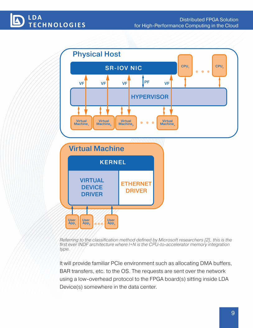
This white paper further describes an operation model called Virtual Device Driver Framework that provides an abstraction level for FPGA resources to be used by servers.
The idea is to load a driver (Virtual Device Driver) into an operating system: either physical or virtual, that will mimic the presence of actual FPGA hardware in the system.
9
Distributed FPGA Solution for High-Performance Computing in the Cloud
Physical Host
HYPERVISOR
VF PF
CPU1 CPUn
VirtualMachine2
VirtualMachine1
VirtualMachine3
VirtualMachinen
SR-IOV NIC
VF VF VF
Virtual Machine
VIRTUALDEVICEDRIVER
KERNEL
ETHERNETDRIVER
User App1
User App2
User Appn
Referring to the classification method defined by Microsoft researchers [2], this is the first ever INDF architecture where I+N is the CPU-to-accelerator memory integration type.
It will provide familiar PCIe environment such as allocating DMA buffers, BAR transfers, etc. to the OS. The requests are sent over the network using a low-overhead protocol to the FPGA board(s) sitting inside LDA Device(s) somewhere in the data center.

10
Distributed FPGA Solution for High-Performance Computing in the Cloud
VIRTUAL DEVICE DRIVERMEMORY ALLOCATIONFOR DMA TRANSFERS
VIRTUAL BAR R/W
RESOURCEBIND API
VIRTUAL INTERRUPTS
FULL FPGA
PARTITION
RESOURCE
to Ethernet
User Application
FPGA network ports will process the incoming data, retrieve the requests and export it to FPGA in native memory mapped or streaming format. Corresponding actions will be repeated on the way back thus completing the loop.
Device AFPGA board
Control Plane
Computational Cores/Partitions
FPGA Resource
Binder
JTAG, USB
to CrossPointFabric
A full set of debugging tools including JTAG, Serial port, power control will be available on the control plane for each board. It will allow programming FPGA universally regardless of board make and model, as well as remote developing and debugging FPGA applications.
11
Distributed FPGA Solution for High-Performance Computing in the Cloud
Another part of Virtual Device Driver Framework is a component running on LDA Devices’ control plane which will communicate with the Virtual Device Driver to perform the FPGA resource allocation (FPGA Resource Binder). It will allow selection of resource type, time, etc.
Possible resource types can be: ` Dedicated full FPGA: will allow loading custom FPGA image received
from Virtual Driver and owning the whole FPGA board. ` FPGA partition: will allow loading compiled partition via partial
reconfiguration protocol. ` FPGA resource: access to FPGAs running predefined IP cores, such
as acceleration, image processing, etc.
The list of available resources, their types, etc. can be made accessible through a Framework Scanning API. This access can be provided to all cloud participants thus supporting all three service levels of FPGA acceleration described by Fahmy and Vipin: FPGAs accelerating the cloud itself, operating systems (both hypervisor and virtual) and end users directly.
In this way many virtual machines can share a single FPGA board, each VM being sure that it has a whole FPGA board fully for itself. Moreover, one VM can be allowed to have multiple FPGAs connected via Virtual Device Driver.
For best performance, the VM host should be equipped with SR-IOV capable NIC.
Summary
This white paper introduced an architecture for the adoption of FPGAs in data centers.

12
Distributed FPGA Solution for High-Performance Computing in the Cloud
Distributed FPGA Grid based on PCIe edge connector repurposing technology and Virtual Device Driver Framework: a network-based abstraction layer together become a Distributed FPGA Solution for High-Performance Computing.
Modern FPGAs have resources that are far too good not to gain entrance into data centers: one way or another it is happening. A solution that will make that entrance seamless is what is needed for FPGAs to gain ubiquitous adoption within the Cloud.
References
[1] S. A. Fahmy and K. Vipin, “A Case for FPGA Accelerators in the Cloud,” Poster at SoCC 2014.
[2] A. M. Caulfield et al., “A Cloud-Scale Acceleration Architecture,” in “Proceedings of the 49th Annual IEEE/ACM International Symposium on Microarchitecture” © 2016 IEEE
[3] A. Putnam et al., “A Reconfigurable Fabric for Accelerating Large-Scale Datacenter Services,” in “Proceeding of the 41st Annual International Symposium on Computer Architecture (ISCA)” © 2014 IEEE
About LDA Technologies
LDA Technologies is company headquartered in Toronto, Canada and specializing in high-performance FPGA-based platforms. LDA Technologies has been manufacturing products and providing consultancy services for customers since 2010. For more information on LDA Technologies visit www.ldatech.com