dissertation
TRANSCRIPT

Student number: 100543130Submitted as part of the requirements for the award of the MSc in InformationSecurity at Royal Holloway, University of London.I declare that this assignment is all my own work and that I have acknowledgedall quotations from the published or unpublished works of other people. I declarethat I have also read the statements on plagiarism in Section 1 of the RegulationsGoverning Examination and Assessment Offences and in accordance with it Isubmit this project report as my own work.
1
Fingerprint Match on-Card Verification In
proximity card based Physical Access Control
Systems - Low Cost Attacks and
Countermeasures
Michael Conway

Executive Summary
Match on-card is an area of developing interest within the domain of authenti-cation. Traditional methods of authentication within Physical Access ControlSystems (PACS) use simple access tokens or in areas where access must be moreheavily restricted, biometric verification. Match on-card (MoC) with the use offingerprints is developing as a popular method of verifying a user whilst bind-ing them to their identity and using the tamper resistent features of a smartcard. Because of its advantages of speed and durability, a proximity interfacecircuit card (PICC) is commonly used within access control systems. In fact, thecombination of proximity tokens with a MoC system offers a reasonably goodcompromise between the security of a template and the affects of constrainedresources within such cards. This project assesses these advantages by lookingat a generic system with its most common aspects derived from what is afford-able at the present time. Using the profile of a potential insider with access toonly moderate resources, some low-cost attacks pertinent to a MoC system arediscussed, highlighting where insider knowledge can prove an advantage. Whilematch on-card may be seen to bind a user to an identity, the attacks presenteddemonstrate that templates may in fact be potentially vulnerable to compro-mise. The issue of template protection is by no means simplistic or absolute.Therefore the provision of security whilst balancing cost and convenience po-tentially involves the same kinds of considerations as per traditional models of2 factor authentication that use knowledge based identity tokens.

Contents
1 Introduction 41.1 Motivation . . . . . . . . . . . . . . . . . . . . . . . . . . . . . . 41.2 Structure of the dissertation . . . . . . . . . . . . . . . . . . . . . 71.3 Statement of Objectives . . . . . . . . . . . . . . . . . . . . . . . 7
2 Key Concepts 82.1 Physical Access Control Systems . . . . . . . . . . . . . . . . . . 82.2 What is a Smart Card? . . . . . . . . . . . . . . . . . . . . . . . 92.3 Contactless Cards . . . . . . . . . . . . . . . . . . . . . . . . . . 112.4 Principle Contactless Card Standards . . . . . . . . . . . . . . . 122.5 ISO 14443 - Proximity Coupling . . . . . . . . . . . . . . . . . . 132.6 Biometric Authentication . . . . . . . . . . . . . . . . . . . . . . 142.7 Errors in Biometric Authentication . . . . . . . . . . . . . . . . . 152.8 Fingerprint-based Authentication . . . . . . . . . . . . . . . . . . 162.9 On-card Verification Strategies . . . . . . . . . . . . . . . . . . . 17
2.9.1 Template on-Card . . . . . . . . . . . . . . . . . . . . . . 182.9.2 Match on-card . . . . . . . . . . . . . . . . . . . . . . . . 182.9.3 System on-card . . . . . . . . . . . . . . . . . . . . . . . . 19
3 The Context 203.1 Resource Limitations on a Smart Card . . . . . . . . . . . . . . . 203.2 Resources on the Microcontroller . . . . . . . . . . . . . . . . . . 21
3.2.1 Processing Capability and Clock signal . . . . . . . . . . . 223.2.2 Memory . . . . . . . . . . . . . . . . . . . . . . . . . . . . 22
3.3 Data Transmission . . . . . . . . . . . . . . . . . . . . . . . . . . 233.4 Impact of Constrained Resources . . . . . . . . . . . . . . . . . . 24
4 Attacks and Countermeasures 254.1 Introduction . . . . . . . . . . . . . . . . . . . . . . . . . . . . . . 25
4.1.1 The MoC PACS system . . . . . . . . . . . . . . . . . . . 264.1.2 The Attacker Profile . . . . . . . . . . . . . . . . . . . . . 274.1.3 The Generic System . . . . . . . . . . . . . . . . . . . . . 27
4.2 Applicable attack routes . . . . . . . . . . . . . . . . . . . . . . . 284.3 Spoofing attacks on the sensor . . . . . . . . . . . . . . . . . . . 29
4.3.1 Anti-spoofing countermeasures and exploitability . . . . . 304.3.2 Feasibility of Spoofing Attacks . . . . . . . . . . . . . . . 31
4.4 Attacks across the Contactless Interface . . . . . . . . . . . . . . 324.4.1 Replay Attack . . . . . . . . . . . . . . . . . . . . . . . . 32
1
4.4.2 Relay Attacks and Countermeasures . . . . . . . . . . . . 334.5 Brute Force Attacks . . . . . . . . . . . . . . . . . . . . . . . . . 344.6 Hill Climbing Attacks . . . . . . . . . . . . . . . . . . . . . . . . 35
4.6.1 Injection Attacks . . . . . . . . . . . . . . . . . . . . . . . 374.7 Template Protection . . . . . . . . . . . . . . . . . . . . . . . . . 384.8 Feature Transformation . . . . . . . . . . . . . . . . . . . . . . . 39
4.8.1 Salting . . . . . . . . . . . . . . . . . . . . . . . . . . . . . 404.8.2 Non-invertible function . . . . . . . . . . . . . . . . . . . 41
4.9 Biometric Cryptosystems . . . . . . . . . . . . . . . . . . . . . . 424.9.1 Key Generation . . . . . . . . . . . . . . . . . . . . . . . . 434.9.2 Key Binding . . . . . . . . . . . . . . . . . . . . . . . . . 434.9.3 Outline of Template Security . . . . . . . . . . . . . . . . 45
5 Summary and Conclusion 475.1 Summary of the Overall Security . . . . . . . . . . . . . . . . . . 475.2 Other Developments with Match on-Card . . . . . . . . . . . . . 475.3 Conclusion . . . . . . . . . . . . . . . . . . . . . . . . . . . . . . 485.4 Summary of Objectives . . . . . . . . . . . . . . . . . . . . . . . 49
6 Appendix 516.1 Carrier Channel Modification . . . . . . . . . . . . . . . . . . . . 516.2 Anticollision . . . . . . . . . . . . . . . . . . . . . . . . . . . . . . 526.3 Data transmission . . . . . . . . . . . . . . . . . . . . . . . . . . 536.4 Challenge-response Protocol . . . . . . . . . . . . . . . . . . . . . 546.5 Dependencies for the Application Specific Transformation Func-
tion Proposed by Cambier . . . . . . . . . . . . . . . . . . . . . . 55
Bibliography 55
2

List of Figures
2.1 A typical access control system [12] . . . . . . . . . . . . . . . . . 102.2 Diagram of an ID-1 smart card [62] . . . . . . . . . . . . . . . . . 122.3 Processing steps for enrollment, verification and identification [40] 152.4 FMR vs FNMR (extracted from [76]) . . . . . . . . . . . . . . . . 162.5 Three Strategies for Fingerprint Verification (extracted from [44]) 18
4.1 A MoC PACS . . . . . . . . . . . . . . . . . . . . . . . . . . . . . 264.2 Hill Climbing Attack System [150] . . . . . . . . . . . . . . . . . 364.3 Template Protection . . . . . . . . . . . . . . . . . . . . . . . . . 394.4 Authentication Process Using Feature Transformation [80] . . . . 40
6.1 Challenge-Response Protocol [28] . . . . . . . . . . . . . . . . . . 546.2 Application Specific Transformation Function [31] . . . . . . . . . 55
3

Chapter 1
Introduction
This section specifically describes the motivation behind this topic and how thesubject area can add further value to the wider field of access control. This willinclude a brief introduction to the topic as a way of leading on to the main bodyof the project.
1.1 Motivation
This project discusses the use of fingerprint verification on contactless (proxim-ity) cards with microprocessors for use within Physical Access Control Systems(PACS). It will evaluate the potential advantages and limitations in terms ofsecurity within such a system. This will be done specifically by way of consid-ering a range of potential attacks that may be performed, when presented witha specific attacker profile and a generic match on-card architecture - typical ofthat within constrained embedded systems, as seen within the current market.
As physical access control concerns the management of direct access to anarea or building, it should be appreciated that it is an essential element in theoverall protection of critical assets. Such systems are generally seen alongsidemyriad perimeter (access) controls in various physical locations including privateorganisations, public attractions or transportation facilities and high securitygovernment buildings, where control of access requires regulation. Althoughthey are generally not considered catch-all solutions, they are often deployedalongside other first line perimeter security controls including wire fences, secu-rity guards, time controlled door locks and surveillance equipment. In practice,electronic PACS are used to regulate access on the basis of predefined accessprofiles or access control lists (ACLs). These ACLs can be used to supportany particular security policy by correctly authorising access to one or morelocation(s), following on from an initial positive identification.
Contactless tokens are commonly used within PACS because of the enhancedspeed, robustness and convenience as a consequence of not having to closely posi-tion or orientate the smart card to communicate with its reader. This technologyalso seems to resolve some of the problems of contamination or degradation ofcontact parts, as is pertinent to contact-based smart card, which may be dam-aged by electrostatic discharge [22]. These cards are used at longer distances(close-coupling RFID systems are the exception[48]), the magnitude of which
4

varies according to the type of system used. This permits users to quickly es-tablish access through an entry point(see [69]) which is further advantageous asthe amount of time required for communication between an external terminaland smart card is reduced, as attributed to the enhanced transmission speedssupported by contactless card standards.
However, one issue with the majority of PACS is that they tend to only usesingle, token-based authentication for access. This may not be an issue withinlow-security environments, but where access needs to be restricted carefully onthe basis of identity, this is certainly an issue. It has been long recognisedthat a token can be “lost, stolen, forgotten or misplaced”[27], which can be-come a significant security risk in such an environment. The alternative,“two-factor” authentication, involves combining an identity token (something youhave) representing a claimed identity and a second factor. This second factorhas traditionally been a memorable credential such as a password, passphraseor PIN (something you know). Regardless, passwords are frequently forgotten,and therefore as a counter-step to resolve this, they are often made simple andpredictable; their overall management can, therefore, be expensive [75]. Thosepasswords that are stored electronically are prone to brute force, else they can bedictionary attacked with relative ease, depending on length, without requiringthe use of particularly advanced hardware or computationally intensive pro-cessing [88]. Moreover, these specific factors only partly answer the question “issomeone who they claim to be?” a question which encompasses the essence iden-tification. Possession or knowledge is an unreliable and circumstantial indicatorof identity.
The use of tokens or “object-based authenticators” combined with an “ID-based authenticator”[119], may add an additional level of security by identifyingsomeone on the basis of their unique biological traits[67]. The perceived advan-tage of this approach is that it is difficult for biometric credentials to be lost,forged, forgotten, shared or easily acquired; unless the biometric authenticationsubsystems are manipulated, only an enrolled person can be verified[78]. Theadvances in general communication technologies, and the frequency in whichpeople travel between physical locations has prompted the use of biometricsas a way of automatically and conveniently establishing identity. Biometric au-thentication is one potential way of circumventing any requirement to hold largedatabases of stored PIN numbers or passwords (hashes), where localised storageof an enrolled template can be adopted instead. Furthermore, biometric authen-tication has been considered to be a reliable, trusted means of binding the ownerof an identity record to that record [84]. The degree to which this is achievedwithin a PACS depends on the additional credentials or protection mechanismsstored on a card[43], and whether the biometric authenticator originated fromthat person whom was present at the time of verification.
Owing to the maturity [27] of its usage and the relative uniqueness and per-manence of fingerprints, this method of authentication is considered one of themore reliable forms of biometric authentication, and is well understood. Finger-prints satisfy the “7 Pillars of biometric wisdom” for the particular reasons thatthey are mature, well understood, reasonably resistant to change and unique[27].Fingerprint sensors are relatively cheap compared to others and therefore theyhave been used in high security environments; in the United States Departmentof Defense(DoD) they are the dominant biometric authenticator[118]. Althoughsome have questioned the efficacy and scientific foundation of fingerprints as a
5

method of uniquely identifying people[121][34] it is indisputable that as a bio-metric method or modality it has been widely studied, and furthermore, it hasbeen used as a contemporary means of identification within automatic identi-fication applications [122]. Certainly high levels of accuracy for this mode ofbiometric authentication have been shown to be demonstrated [96] and it is thefirst type of biometric introduced into true match on-card technology [21]. Thisprovides a strong justification as to why this biometric has been chosen, aboveothers, to be included within the framework of discussion.
In terms of the various configurations used for verification using a card,match on-card seems the most ideal in terms of balancing the protection of abiometric template on a card, and accounting for resource limitations in line withthose at present time. In this configuration specifically, the tamper-resistantenvironment of the card is used to both house the template and perform thematch function. This reduces the attack surface by ensuring that the tempateremains on the card, and only the result of a matching- or live- template is sent.Storing the card also removes any overhead from maintaining large databasesof templates within potentially insure databases.
However, there are several constraints and limitations in terms of the re-sources available to a card. Among these limitations are the amount of powerand clock provided by the card, as well as further limitations within the RAM,ROM, EEPROM and transmission speed, as distinct from conventional PC ar-chitectures. The architecture and implementation of such a solution can there-fore vary, and similarly the potentially insecure contactless interface may beexploited. All of these aspects have a direct bearing on the time and reliabilityof the verification - and therefore - end-to-end process of access control us-ing fingerprint verification within a smart card. Furthermore, it is the case thatboth the contactless communication interface and biometric system componentspossess vulnerabilities that may be exploited.
It should be noted that at the time of writing there are a few major devel-opments progressing that have combined these aspects.
1. Within the US, there are some developments occuring:
• The U.S Department of Defense (DoD) has taken an interest in thisarea since the passing of the U.S Homeland Security PresidentialDirective 12 or HSPD-12 [153]. Personal Identification Verification(PIV) cards required to be compliant with the follow-on U.S. stan-dard FIPS-120 are one particular example of where development inthis area is taking place.
• The contactless version of the Common Access Card, CAC [117] is-sued by the DoD to the DoD community, is another example of adevelopment combining the use of on-card verification with contact-less technology. Early tests focused mainly on template on-card ver-ification, but since then it was demonstrated that these cards canperform match on-card across an encrypted channel [136] and sup-port for match on-card over a contactless interface exists within thenext-generation cards.
2. One of the most pertinent examples of where this combination of tech-nological factors is being researched is within the Europe Union, under
6

the multi-million pound funded “Turbine” Project [51]. The objective ofthis project is to research and ultimately develop e-identity solutions thatincorporate fingerprint-based biometric authentication.
With these developments in mind, the principle aim of this project is tohighlight some of the restrictions involved in incorporating fingerprint verifica-tion onto a PICC and how the compromises made to the architecture, in orderto balance cost with practicality, can result in the presence of vulnerabilitieswithin PACS. The specific areas of focus, to this end, will be the attacks thatexploit these vulnerabilities, and those which are low cost and unique to matchon-card, as well as the various means in which these may be mitigated.
1.2 Structure of the dissertation
This project will closely follow the objectives as set out below, beginning inChapter 2 with the key concepts behind a contactless MoC implementationwithin a PACS. This lays out the the concepts and technologies behind thevarious components of generic contactless access control and biometric systems.
Chapter 3 discusses the resource limitations on embedded smart card systemsand how match on-card offers a balanced approach that considers these, giventhe challenges of integrating fingerprint verification onto a card in line withresource constraints. It also details the compromises made on such a system.
Chapter 4 discusses a range of attacks that can be conducted against ageneric solution, in accordance with a specific attacker profile, as well as thecountermeasures that can be implemented against such attacks. This will in-clude an analysis of how realistic these possibilities are in relation to both therobustness of the system and the resources of the attacker. Various assumptionsand exclusions will be applied to scope this environment.
The final chapter, Chapter 5, will conclude with a summary evaluation of therelative levels of security as a consequence of match on-card implementations,their practicality for access control environments and some of the activities beingdone to harmonise/standardise efforts to develop this area across industry.
1.3 Statement of Objectives
1. To discuss the main resource constraints on microprocessing proximitycards and how this can lead to vulnerabilities.
2. To discuss a range of low-cost attacks that are applicable to the environ-ment being considered.
3. To discuss the various countermeasures to the above attacks and potentialways to secure templates.
4. To evaluate the potential security advantages or disadvantages of MoCimplemnentations.
7

Chapter 2
Key Concepts
This chapter presents a background to the underlying concepts and technologiesbehind a physical access control system using fingerprint-based verification ona contactless smart card. The concepts within this section will be:
1. Access Control Systems.
2. Smart cards - what they are, their properties, and the types of smart card.
3. Proximity Coupling - the technology most frequently used by contactlessaccess tokens.
4. Biometric Authentication - including the subtypes identification and ver-ification.
5. Errors in Biometric Authentication.
6. Fingerprint-based Authentication.
7. Verification Strategies.
2.1 Physical Access Control Systems
In Chapter 1, it was briefly explained that access control is the automatedprocess of authorising and granting access to a physical location. To buildon this definition, a reference should be made to the international standardISO/IEC 10181 part 3[72], which specifies a security framework for access controlin open systems. This defines access control as “The process of determiningwhich uses of resources within an Open System environment are permitted and,where appropriate, preventing unauthorized access”. As the scope of this projectconcerns physical access control, this definition should be applied to the morefocused remit of physical access control environments.
In general, this process starts when a user presents an authenticator to areading device attached adjacent to (or more usually - directly) at the accesspoint. This reading device is responsible for capturing information from the au-thenticator; typically a chip card, and passing this on to a portal∗. During this
∗The term portal is an alternative to control panel, as per the definition within[32]
8
process, the smart card may or may not trust the reading device and thereforefurther validation or authentication mechanisms may be required. The portalthen communicates further with the additional access control subsystems toauthorise access, the set up for which may vary. In many access control sys-tems, portals are connected to host computers which are themselves connectedto back-end databases or access control servers (usually containing encryptedand/or hash-protected data), against which a live credential is compared. Alter-natively, the reader itself may have enough logic to authenticate the presentedcredentials. This matching function is normally carried out at the applicationlayer using matching software resident either on the host computer, or within anembedded/smart card operating system, depending on whether more enhancedauthentication mechanisms are used.
Once there has been a positive identification match, the embedded deviceor terminal communicates with the portal and transmissions are sent to a door-release mechanism or “door strike” and an aural sound may be produced, in-dicating that access has been granted (or in some cases denied). Figure 2.1illustrates this process.
In contactless physical access control systems incorporating microprocessingcards, the door reader and card communicate via radio frequency (RF) technol-ogy, under which the most widely used technology - proximity coupling, is used,as described in 2.5. In this case, the contactless card is presented within theRF field and is powered by, and communicates with the reader. Any additionalfactors - PIN or biometric - may be used in combination, and tend to transmitby a separate interface, commonly a serial interface.
Regardless of whether or not authentication is performed within the closedenvironment of an embedded system, access to each physical location can be de-fined and enforced by the use of specific access control lists (ACLs), a type of ac-cess control scheme used enforce a system specific policy (SSP). Such a policy isoften derived from an overarching enterprise information security policy (EISP)or other high-level security policy, depending on the type of organisation[26].Higher security environments often employ the use of formal access controlframeworks supported by granular ACLs, which should be under strict con-trol. This is in order that access privileges are updated, restricted or revokedwhen necessary. As within the framework specified under [72], access controlmechanisms utilise access control information (ACI), including ACLs, which isused to make a decision by an access control enforcement function (AEF), whichis itself mediated by an access control decision function (ADI). Although thesecomponents are logically separate, they may be part of the same componentwithin an access control system. For example (as in this case), the systemmay be configured so that the AEF and ADF are on the control panel and theACI/ACL information exists on the smart card or backend server.
2.2 What is a Smart Card?
Smart cards are currently widely used across several industries, and have beenadopted to suit many purposes, in particular tokens used for authentication andaccess control. A generalised definition of a smart card is “a plastic card the sizeof an ordinary credit card with a chip that holds a microprocessor and a data-storage unit”[68], which is a useful but simplistic description of a smart card.
9

Figure 2.1: A typical access control system [12]
Smart cards have been around for some time the first example of which wasthe “Diners Club” card, a payment card used in the travel and entertainmentindustry[124]
Smart cards can be broadly grouped into 2 major categories, the first ofwhich is known as the “dumb” smart card because of its limited processingcapabilities. This category includes the “memory card”, the first example ofa card containing a microprocessor chip, which contains only memory modulesand practically no CPU power. A key component within the memory cardarchitecture is the security logic, which mediates memory(ROM and EEPROM)access. As its name suggests, it is responsible for providing additional securitywithin the chip and its activity ranges from simple write protection to basicencryption functions in more advance adaptations.[124]
The second group of smart cards are the “true” smart cards, which have theextended ability to perform processing functions, carried out by an embeddedsmart chip processor (CPU).[49]. State-of-the-art microprocessing cards have afar greater processing capacity and more memory than dumb cards, and theselevels are advancing. The higher quantities of memory and processing capabilitycan support many advanced additional features such as multiple applicationsand high-level programming languages (APIs) to support specialised applica-tions including match on-card implementations. This is distinct from the dumbsmart cards. Advanced microprocessor smart cards also support fairly advancedcoprocessors “utilized for accelerating the computation of time-critical proce-dures relieving the systems microprocessor from these application parts”[53].Many examples of these exist[110] including cryptographic coprocessors, whichhave been developed to support both symmetric and public key cryptography[48]. In the latter case, this is done by carrying out performance-intensive mod-ular exponentiations for cryptographic algorithms such as RSA.[65] These cardsconsist of operating systems that are multi-threaded and capable of multitask-ing, ensuring that data stored on the cards need not leave the card itself.[22]
10

Match on-card implementations can only be supported by these advancedcards because of the resources required on what are, in general, constrainedand limited processing environments. Such limits, and their effects on on-cardverification, will be discussed in 3.1.
However, generally speaking, a smart card should satisfy the following qual-ities [103]:
1. It can participate in an automated electronic transaction.
2. It is used primarily to add security.
3. It is not easily forged or copied.
4. It can store data securely.
5. It can host/run a range of security algorithms and functions.
2.3 Contactless Cards
Within the category of true smart cards are the “Contact” and “Contactless”cards, both of which require a smart card terminal or reader for the purposeof rendering data to and from the host, and powering the smart card chip. Ingeneral, cards with IC chips will have 8 electrical contacts (C1 to C8) each ofwhich with a specific purpose as according to the standard ISO/IEC 7816 part2. These cards are so-called as they must be inserted into an external smartcard reader, whereupon there is physical contact between the electrical contactswithin the reader and those on the smart card module, with which they areinterfaced (aligned). In order for the card to be correctly read, this process alsorequires that efforts are made to correctly orientate it.
However, contactless cards contain an additional communications interface,most commonly a Radio Frequency (RF) interface. This employs the use ofelectronic devices attached to objects or hosts, using either RF or magnetic fieldvariations to communicate data [56][48]. The main components that performthe communication dialogue are an external reading device containing a controlunit and an RF module, and a transponder device responsible for carrying data,containing a microchip. Both of these components have coupling devices thatcommunicate across an RF channel, so that data can be transferred both ways.
Rather significantly, there is a difference between RF identification in thecontext of RFID tags and the use of RF technology in PACS (smart) tokens [13].These latter smart devices typically should be consistent with the definition“intelligent read-write devices capable of storing different kinds of data andoperate at different ranges” as in [12]. Simple contactless tokens tend to be littlemore than state machines, but as stated, cards that are used for match on-cardverification have operating systems and advanced processing capabilities.
An additional assumption that has been consistently held for some time isthat smart cards predominantly fall into the ID-1 card format family , whichconsists of dimensions 85.6mm x 53.98mm x 0.76mm (see figure 2.2)[62]. Thisis as defined by the international standard ISO 7810-1 [71]. However, there areother smaller card formats that also exist, including the ID-000 format, which atthe lower end of the scale can be 25mm x 15mm, and the ID-00 card, dimensionsfor which are an intermediate of the formative[87]. However, the most widely
11

Figure 2.2: Diagram of an ID-1 smart card [62]
used access control and identity tokens to date still fall within this ID-1 format.The physical format and properties of the card are of significance, because theyimpact the overall availaility of resources within a card (see 3.1).
2.4 Principle Contactless Card Standards
There are 3 main international standards for contactless systems, all operating ata high frequency band: (1) ISO/IEC 14443 - Proximity Coupling, (2) ISO/IEC15693 - Vicinity Coupling and (3) ISO/IEC 18092 - Near Field Communication,all of which use the operating frequency of 13.56MHz. †. The signal interfaces,protocols and operating ranges of these system are specified in each of thestandards, which also have the following features:
• Read/write capability including the capacity to store biometric templatesand PINs
• Capability to add security features (although not explicitly designated)including cryptographic algorithms and digital signatures
• Support for multiple technologies and interfaces
• Authentication between the contactless reader and the contactless card
†Close-contact cards have not been specified as they require precise orientation and arenot in the HF range
12

2.5 ISO 14443 - Proximity Coupling
Of all of these standards, ISO/IEC 14443[1] is the most widely used for con-tactless systems [142] and has been described as “the standard of choice fore-passports, credit cards and most access control systems.”[103]. Inpractice, however, compliance against this standard is most often obtained forcard readers, due to the sheer variety and volume of contactless cards that areproduced.
Part 1 of the standard defines the physical properties of the card includingphysical tolerances and environmental stresses, and its dimensions as in linewith the ID-1 format are specified in ISO/IEC 7810 part 1[71].
The second part [2] specifies RF power and signal interface, including detailsregarding data modulation and bit representation (coding). Specifications forthe initialisation of communication, use of commands and the data byte formatof frames are included in part 3, as well as anticollision methods. Finally, Part4 [4] defines the transmission protocols.
These systems operate at a range of 0 to 10cm and consist of notionalProximity Integrated Circuit Cards (PICCs) and Proximity Coupling Devices(PCDs) which transfer data using “proximity coupling” [48]. Under thestandard, PICCs are passive tokens, deriving their power and clock from PCDs,and transferring data across an alternating high-frequency electromagnetic fieldbefore communicating across the channel. Power is provided by looped coils ofwire in the PCD antenna (consisting of 3-6 windings) when current is applied tothe circuit and the electromagnetic field is produced. When the PICC is in thefield range of the PCD, power is transfered across to the PICC transponder coilas a result of magnetic flux transfer. Resonant transponder coils and the capac-itor within the PICC then form a circuit, which is powered at a transmissionfrequency equivalent to that of the PCD. This sets up a carrier channel betweenthe PCD and PICC, along which the PCD can transfer data using direct datamodulation, which alters the baseband signal of the carrier. In the reverse di-rection, load modulation is used to alter impedance in the antenna of the PCD,i.e. the PCD is induced to carry out amplitude modulation by responding tothe feedback generated in antenna. ∗
The exact approach of data modulation differs according to 2 disparate sig-naling interfaces specified in part 2 of the standard: type A and type B. TypeA is used for the majority of contactless smart cards and differs from type B in3 main areas [2]:
• The exact method for modulating the magnetic field
• The bit/byte coding
• The anticollision method
The latter of these - anticollision - is another important aspect covered bythe standard, in part 3. A collision is the term associated with interferencebetween data blocks of a PICC when more than one PICC is present within theinterrogation field of a PCD. Clearly this can be an issue as it is not desirablefor data to be corrupted, which can significantly impact verification times andauthentication of PICCs to the PCD. Anticollision measures are important in
∗see 6.1 for further details
13
ensuring that individual PICCs can be chosen for communication as necessary,which is of significant importance - multi-access for PICCs is essential in anaccess control environment where many PICCs may be present. See 6.2 formore details.
2.6 Biometric Authentication
Biometric authentication is the process of identifying a person according toindividual behavioural or physical(physiological) characteristics [105], which iscarried out by a “biometric system.” A biometric system carries out the identifi-cation process by acquiring raw data from a person using a sensor(data acquisi-tion), converting it into digitised data and then further processing it to generatea template representative of a distinctive feature set, in a process known as fea-ture extraction [79]. While the template is being extracted at any one time, thetemplate is referred to as a live template.
During enrollment the template may undergo processing to ensure that thequality is of an acceptable saliency∗ before it is then stored, either in a stor-age subsystem such as a database, or in a smart token(as is the case for theMoC solution being considered). This template is often described as a referencetemplate. The authentication process then takes place and one or more refer-ence templates are compared with a single live template representing a claimedidentity, using a biometric feature matcher [76].
The outcome of the matching stage is a quantifiable measurement of thedegree of similarity between templates - known as a matching score, or a binarydecision (positive or negative access). In general, there are five major subsystems(modules) in a generic biometric authentication system responsible for carryingout these steps: (1) sensor, (2) feature extractor, (3) storage subsystem, (4)matching module (5) decision module [80].
The two subtypes of authentication method are identification which involvesa 1:n comparison and verification, a 1:1 comparison[57]. In other words, theformer compares a live identity with several stored reference templates (usedcommonly in law enforcement when attempting to identify an individual froma pool of credentials) and the latter with a single reference template. Of thesetypes, it is a verififcation system that will be the focus in this project.
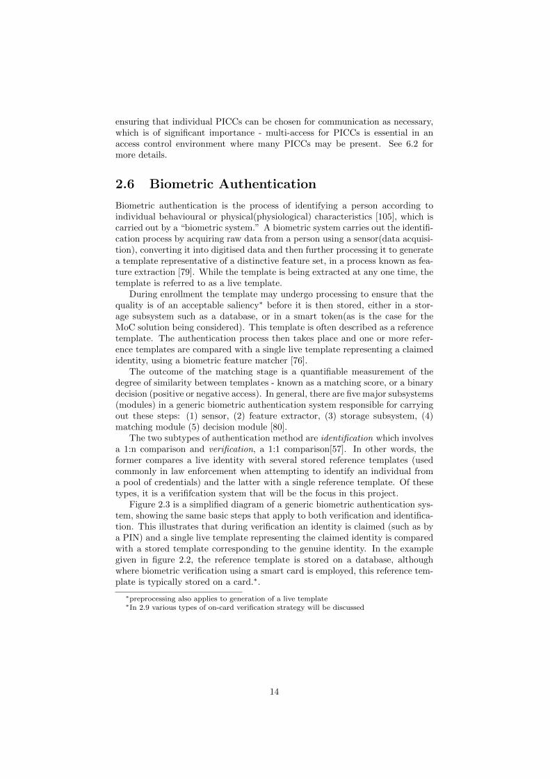
Figure 2.3 is a simplified diagram of a generic biometric authentication sys-tem, showing the same basic steps that apply to both verification and identifica-tion. This illustrates that during verification an identity is claimed (such as bya PIN) and a single live template representing the claimed identity is comparedwith a stored template corresponding to the genuine identity. In the examplegiven in figure 2.2, the reference template is stored on a database, althoughwhere biometric verification using a smart card is employed, this reference tem-plate is typically stored on a card.∗.
∗preprocessing also applies to generation of a live template∗In 2.9 various types of on-card verification strategy will be discussed
14

Figure 2.3: Processing steps for enrollment, verification and identification [40]
2.7 Errors in Biometric Authentication
Biometric authentication based on physiological features is wide-ranging andincludes fingerprint, iris, retinal, facial, vein-pattern and hand geometry recog-nition among the most popular methods. Regardless of the feature, or biomet-ric mode, there are considerations regarding their performance that have to betaken into account, especially when designing a system. In any biometric sys-tem, it is unlikely that genuine live samples will be consistently identical, asthey are affected by a range of issues [75] particularly those resulting from theinconsistent presentation of the trait and background noise/distortion. Eachsystem is therefore designed with a particular tolerance threshold, below whicha sample is rejected. By its own very nature, the biometric matching processis probabilistic [23] and results in errors occurring, which are affected by thethreshold levels that are set. This gives rise to two major types of error: falsematch or false non-match errors. The probabilities of either occurrences arerespectively expressed as the “false match rate”(FMR) and “false non-matchrate” (FNMR)[79].∗ Both rates are influenced by the threshold of the system sothat as it decreases, more false matches are tolerated, ergo the false match rateincreases; and the same is true of the opposite. Various attempts have thus beenmade to formulate consistent methods to calculate error rates [152] and assessoverall system performance [96]. One way in which this type of assessment isillustrated is by the use of a Receiver Operating Characteristic (ROC) curve,which plots the FMR against FNMR at different operating points [77]. Theerror rate at a particular threshold when both of these rates are equal, is knownas the Equal Error Rate (EER) and is a useful indication of the accuracy of abiometric system as illustrated in figure 2.4.
The trade off between FMR and FNMR is an important consideration for theMatch on-Card solution, since any successful attempts made by an impostor, togain access, will warrant an increase in the tolerance threshold of the system.This could potentially impact the convenience of the access control system if an
∗there other kinds of error - failure to enroll (FTE) and failure to acquire (FTA). [26],[99]
15

Figure 2.4: FMR vs FNMR (extracted from [76])
unacceptable number of false non-matches results from such a change.
2.8 Fingerprint-based Authentication
Fingerprint-based authentication appertains to the recognition of fingerprints,the unique features displayed on the epidermis of a digit(or finger), which areformed during early fetal development [18]. The features of the digit includepapillary ridges and furrow (valley) patterns, from which singularities and moreexpress features of the ridges are derived(minutiae) among which are ridge end-ings, bifurcations and lakes [74].
The process of fingerprint authentication involves the same generic steps andsubsystems as in 2.6. A basic overview of this process shall be described in thissection.
The processes of both enrollment and authentication involve similar basicsteps. During the process of fingerprint image data acquisition, a human digitis presented to a fingerprint sensor responsible for reading the biometric featureand converting it to raw data (image) using a fingerprint sensor. There arenumerous sensing technologies (as will be discussed in 4.3), the majority of whichfall within the optical and solid-state families, each using distinct techniques tocapture fingerprint images.
Prior to feature extraction, an optional quality assessment module may beused to assess the image for variations in quality such as broken or unseparatedridges, image contrast, ridge aberrations and other varying conditions [80][79].
16

In many cases this module assigns a quality metric between 0 and 1 [27], in-creasing in terms of accuracy. Quality assessment subsystems are common intraditional AFAS systems as opposed to embedded systems, again due to re-source constraints.
Once a fingerprint has been scanned by a fingerprint sensor, it typicallyfirst digitised and then binarised, where a low pass filter is used to smoothhigh frequency image regions thereby improving clarity and circumventing noisyareas of the fingerprint and background [154]. This can be performed by one ofmany mechanisms, for example those based on normalisation (to a “pre-specifiedmean and variance”, local orientation and frequency variations or contextualfiltering [79]). The image can then be further enhanced by refinement into athin skeleton, of width one pixel, from which features can be extracted [109][44].
The template signal is next passed to a feature extraction subsystem toextrapolate features and render the signal into a format suitable for match-ing. Generally representations are based on spacial locations correspondingto orientation and the type of minutia[77][109] used in point-matching. How-ever, there are alternative approaches such as those involving algorithms, whichact on the number of ridges per distance (ridge density), pattern class, rota-tion and shift[128]. Novel approaches have been proposed which involve usingcharacteristic features verging the minutiae, such as notional adjacent featurevectors[146], which have unique global transformations such as rotation andtranslation. The majority of these approaches tend to be based on proprietaryalgorithms.
During enrollment, the selected minutiae points (usually between one andtwenty) are stored within an enrolled template [108], which can then be usedfor comparison in the matching module, during the authentication stage. Thisis carried out by a decision making subsystem, and is often based on the degreeof accurate matching of minutiae points. One such way this can be done is bydividing the number of successfully correlated points by the total number in atemplate. This gives a metric between 0 and 1 (as previously described) where1 is a 100% match and a threshold is chosen within this range, under whichaccess authentication is denied.
2.9 On-card Verification Strategies
Three dominant strategies exist for verification using a smart card[44], all differ-ing in how the template is used and the location in which the matching processtakes place as in figure 2.5.
• (i) Template on Card (ToC), otherwise known as Storage on-card.
• (ii) Match on-Card(MoC)
• (iii) System On-Card (SoC), as illustrated in figure 2.5.
.All three of these strategies differ in how and where the verification process
takes place.
17

Figure 2.5: Three Strategies for Fingerprint Verification (extracted from [44])
2.9.1 Template on-Card
Template on-Card (ToC) - also known as storage on-Card, is a form of biometricverification whereby the smart card acts simply as a storage device that holdsthe template. In this configuration, the matching is not done within the smartcard; the template is instead transmitted to an external device that performsall functions required for matching i.e. image scanning, feature extraction andmatching etc.
Where a positive match has been made by the terminal within a PACS, theterminal will securely pass the result to the other subsytems. Hence beyondthe transmission of the template, the (PICC) card is no longer involved for thatinstance of verification.
Consequently, this is the least secure of the three strategies, as the expo-sure of the template representative (as a result of leaving the card) renders itvulnerable to interception. Across a potentially insecure RF channel, this re-quires cryptographic protection or the use of digital signatures to secure thetemplate during communication. Cards used for this process tend to be lowcost state-machines, which presents a challenge to this end. Furthermore, veri-fication must take place in a device attached to a database, server or network,which are potential points of vulnerability [21]. This method is therefore notideal for use in a secure PACS.
2.9.2 Match on-card
Match on-card (MoC) verification does not require that a template or its repre-sentative leave the card at any stage, unlike ToC. Instead, the matching stagetakes place within a smart card, without requiring that the stored templateleaves the card.
In this case, a master template is generated during enrollment, as well asother identifiable information associated with the template, which are storedon a card instead of a database subsystem. The sensor is located within theterminal, where a live (query) template or representative thereof is produced
18
and passed on to the card, where the matching is algorithm is executed. Conse-quently any card used in this system requires a microprocessor and an operatingsystem to invoke the matching algorithm, which may also carry out feature ex-traction prior to the matching process[44]. Cards used for MoC implementationsare capable of possessing advanced microprocessors and smart card operatingsystems that can support this. In addition these operating systems can carryout authentication, cryptographic and matching operations.
Once the matching process has occurred within the card, a result derivedfrom the matching process is transferred across the interface between the cardand reader. The security is enhanced in this system, as the tamper resistantenvironment of a smart card is used to protect the template and can only beaccessed with a concerted amount of effort and resources available. A usefulexample of the kind of architecture used for this process is in [120] which il-lustrates how a match algorithm stored within the chip (using native code) isused to process the matching before the result following a successful match issecurely passed up to the application layer.
However, as will be discussed, there are still points of attack that exist inthis system.
2.9.3 System on-card
In a system on-Card (SoC) verification system, the data acquisition, featureextraction and matching processes all take place within the smart card, as thefingerprint sensor is present within the card. Cards using this type of verificationsystem must be capable of high performance and their components are likely tobe expensive.
Potentially the most secure implementation of these strategies is SoC ver-ification. However, such systems would require investment in state of the artmicrocontrollers, including embedded co-processors and additional processingcomponents [50], which, within a high-volume PACS may not always be cost-effective. Even CPU chips (processors) up to 32-bit RISC do not fall withinacceptable processing thresholds to cope with performing feature extraction orimage processing computations at least not without significant investment inadditional memory and components to speed up this process [44]. Althoughenhancements are certainly progressing in this area and various modified archi-tectures have been proposed [50], cards used with SoC based implementationsare not widely used, particularly in microprocessing cards with proximity inter-faces.
This leaves MoC as the most widely accepted form of biometric verifica-tion that involves the use of a smart card template and a suitable compromisebetween capability and security.
19

Chapter 3
The Context
The purpose of this chapter to is to discuss the restricted processing capabilitiesof PICCs and how this affects the appropriate choice of hardware, software andadditional logical components therein. This will form the basis of a scoped accesscontrol environment, the attacks against which (and their countermeasures) willbe discussed in Chapter 4.
This chapter begins with a discussion of the power and processing constraintson microprocessing smart cards, particularly those with proximity coupling in-terfaces (as discussed in section 2.3), and continues with a discussion about howthis affects their performance capabilities. Specifically this will focus on howthese limitations may affect the choice of both hardware and logical componentson the PICC and PCD, and in the latter case the level of feature representationwithin an enrolled or live fingerprint template. It is discussed as to how thisultimately influences the overall physical access control environment and howthe MoC solution provides the best overall compromise between capability, cost,processing/matching times and security requirements. This will set the scene fora discussion of a range of application attacks on these constrained environmentsand their feasibility, as in Chapter 4.
The following points will be covered in this chapter, within the various sec-tions:
1. Resource limitations on a smart card in general.
2. Resource limitations on the microcontroller - clock, power, memory andtransmission speed.
3. Resource limitations in data transmission speed.
3.1 Resource Limitations on a Smart Card
Smart cards by their nature are a lot smaller and have restricted capabilities ascompared with conventional computers. A large reason for the limitations in thisarea is because of the size specifications influenced (and brought on) both by thetrend in industry and standardisation in the smart card market sector. The ID-1 cards as described in section 2.2 and with which contactless smart cards mustcomply under ISO/IEC 14443, must withstand the respective bending/stress
20

tests specified therein, in order that they are suitably flexible to avoid damage,as per ISO10373-1 [73]; in addition they must adhere to a reasonably smallform factor. This significantly limits the smart card die and capacitor size, andthe specific components included within the smart card microcontroller (i.e.memory and processor).
3.2 Resources on the Microcontroller
.A microprocessing smart card will, by its own nature, contain a (sub-electrical
contact) microcontroller, within which the main functional resources are con-tained. It will contain the following components as a minimum [46]:
• CPU
• Memory: RAM, ROM and EEPROM.
These components are the basic limiting factors with regard the overall per-formance of a smart card and its ability to perform functions efficiently. Thefunctions of these components are summarised in the table that follows below.
Resource FunctionCPU The processing unit within the microcontroller of a smart
chip. It is responsible for all of the card’s logic and activi-ties, is closely associated with the memory modules withinthe card, and is directly affected by the clock speed (signal).
ROM The memory module that has data written to it once duringthe lifetime of a smart card, after which time the contentsbecome read-only. This data is consistent within a batch ofa production run. In the more advanced smart cards thiscontains the elementary parts of an operating system, asEEPROM can be used to load any additional data or code.
RAM The memory module containing temporary volatile dataused for storage of data (i.e. working memory), used forrun-time processing.
EEPROM The EEPROM is programmable memory, providing the im-portant task of extending the functional capabilities of achip card. This is particularly useful when the smart cardneeds to be updated, for example when adding the capa-bility of a card to stored fingerprint minutiae matching ap-plication code, as this can be done after the manufacturingprocess.
In addition to the latter 3 types of on-board chip memory, flash memoryhas been integrated into some of the latest chip cards, as it has faster writecapability, generally ages better than EEPROM and configurations can be softloaded. However, there are security concerns about flash memory and its highercosts, and so at the present time, it is rarely used for verification on-card withinPICCs.
21

3.2.1 Processing Capability and Clock signal
The vast majority of smart cards do not generate their own clock signal, but arereliant on the clock signal of an external terminal, from which the internal clocksignal (that powers the logic of the microprocessor) is derived. The resultantinternal clock signal of a processor is normally around half that of the externalclock signal generated from the oscillators of a reading device, which furtheraffects the ability of the processor to perform instructions.
Under the latest revision of the ISO/IEC standard 7816-3 [70], the thresh-olds for the “VCC” contact of a smart card (compliant with ISO standards)associated with supply voltage and and supply current are specified for smartcard types A, B and C. The minimum and maximum power supply values spec-ified are 1.62 and 5.5V and the minimum and maximum supply current valuesare specified at 30 and 60 mA respectively.
The standard also specifies thresholds for the CLK contact which receives theclock signal. The recommended values for when the clock is active is 1MHz andmaximum is 5MHz, although the clock tends to be set at 3.57MHz. [70]. This issmall and becomes a particularly limiting factor under the ID-1 standard card.This contrasts with the capabilities of state of the art conventional PersonalComputers, which commonly run within the GHz range in respect of clocksignal.
These constraints can be overcome by the use of additional circuitry tocontrol the internal clock frequency, including phase-lock loops (PLLs )[60].These are circuits functionally located between the external and internal clocks,and have been used in embedded systems as a means to boost the frequency ofthe internal clock signal [112] derived from that of the external clock (frequencymultiplication). The latest version of ISO/IEC7816 part 3 (2006) accounts fora maximum clock frequency of 20MHz, which would support this.
In modern smart cards, these components are included: - to resolve issues ofpower and clock issues - during the design phase of contact-based smart cards- for security purposes [59] in biometric-capable embedded systems [11] and asa method for efficient power management ∗. However, this is not always ideal,as clock multipliers can interfere with the clock signal in RF based systems[90],and do not have any bearing on on EEPROM read/write cycles.
Dedicated crypto-coprocessors have been used to support cryptographic pro-cessing at a low level, an essential requirement for sufficient security over a con-tactless interface [36]. The issue of their implementation is no longer consideredone of the important influential factors in terms of the overall processing timeof a smart card[100]. In the current market, RISC architecture-based chips typ-ically contain these, an example of which is the FameXE coprocessor within theP5CD036 chip by NXP, [116] which supports advanced cryptosystems.
3.2.2 Memory
The memory modules are all limited in capacity compared to those within PCs.The ROM, while the most efficient in terms of packing density, allows soft-ware to be written once-only. Therefore it is typical that the operating systemis loaded into it and remains permanently written therein. It is not used for
∗A PLL can also offset power consumption and regulate clock signal as a consequence ofheavy-duty processing otherwise carried out by any coprocessor with the microcontroller
22

any transient storage or dynamic data, although depending on the smart cardROM mask it can be designed to contain the matching code (during manufac-turing), in order to reduce the storage burden on the rest of the memory on themicrocontroller. However, adding specialiased functionality to ROM lengthensthe term of the manufacturing process, contributing to increased productioncosts. Regardless, with improvements in storage capacity in current generationsof smart cards, (particularly EEPROM) both advanced smart card operatingsystems and platforms have been developed that support multiple applications(and programming interfaces) that extend beyond previous resource limitations.
EEPROM is the next most useful in terms of dynamic storage and overallpacking density. EEPROM does age, however, and is limited to a typical writecycle threshold of “between 10 000 and 100 000 for EEPROM cells”[48] perlifetime. EEPROM is important in the context of MoC systems as it is used asnon-volatile long-term storage and is used to store the matching code and/orreference template of the enrolled user. In microprocessing cards such as theJava Card, applets that form part of the Java Card API [21] are stored inEEPROM.
In order to write to EEPROM, the appropriate power supply requires awrite voltage of 12V, although the RF carriers are supplied with 3V and 5V(as constrained by ISO/IEC 7816). Overall, the power provided by the PCDto the card is restricted by the electromagnetic spectrum (as specified by ISO14443) to a value of 7.5 H/m [94]. The extra voltage is provided by a cascadedcharging pump on the microcontroller, which is, as standard, integrated into asmart card - up to 25V.
RAM is the least densely packed and at a premium compared with the othermemory modules within the microcontroller. This is also a crucial element ofthe on-card matching process as it is used to store dynamic, volatile data andtherefore influences the overall runtime environment. This would include anysession data present as well any results required in computations, i.e. matchingresults. This is the fastest form of memory to write to (approximately x 1000)[120]
Historically, and until recently, memory has been a restrictive factor forsmart cards, with a direct bearing on computations, which themeselves requiremore complex processing requirements, both in terms of running matching algo-rithms as well as any cryptographic security mechanisms incorporated. Nonethe-less, improvements in this space are certainly being seen.
One of the issues that constrained PICCS have (associated with memory)is that the template sizes held on the RAM are much smaller compared tothe images stored within conventional online databases. As a result biometrictemplate sizes are short and tend to be around 512 bytes [30] and as such tendto be transmitted within multiple APDU structures [44].
3.3 Data Transmission
Transmission speeds are naturally among the most influential aspects in termsof the performance times for on-card verification.
As specified in part 3 of ISO 7816 [70] data at the physical layer are sentvia asynchronous half-duplex connections, whereby bit streams of data are sent.The equivalent protocols are specified for contactless transmission and are also
23

referred to as T=CL [48]. Any aggregated blocks of data are therefore requiredto be organised with contingent synchronisation and termination bits flankingthe data. Timing must be coordinated between the reading device and thesmart card, however this process is largely dependent on the clock signal ofthe microcontroller. The more commonly deployed 32-bit RISC processors arebeing used alongside increased quantities of RAM and EEPROM, such thatthis is becoming more increasingly tolerated. In contactless systems, type APICCs support higher communication rates up to 848Kbps.[2]. This supportsfaster data transfers than the serial interfaces used in many match on-cardimplementations.
Within a smart card, the transport and application layer message blocksizes are limited. This is also the case for contactless cards which use the T=CLprotocol, where the APDUs that fit within the frames are bound by an upperlimit of 255 bytes. These limits are again bound by the specifications of the14443 ISO standard, which has resulted in a fragmented system of transmission,despite the allowance for chaining of blocks under the message protocol. Inaddition, the I/O buffer sizes are limited, which is a significant influential factorin the timing of communications [85]. In response to this, the buffers can beincreased to tolerate larger message sizes, however this will affect the runtimeenvironment and demand increased RAM capacity. As RAM is at a premiumin smart cards, even to an extent in current generation microprocessors, thisincreases its cost.
3.4 Impact of Constrained Resources
These restrictions all affect the timing in which verification can be performed ona smart card. What this means in practice, is that extra expense is required inorder to ensure that the each of the microcontoller components are sufficientlyadvanced that verification can be carried out within a suitable length of time.At present time, state-of-the-art specifications do exist, for example, the mostrecent version of Gemalto’s .NET card, (which can be utilised with .NET matchon-card application software for match on-card verification) is the .NET v2+card (chip model SLE88CFX4000P). This card has 400kB EEPROM, 16kBRAM (and in addition, an internal clock at 66MHz, external clock at up to10MHz and voltage between 1.52 and 5.5V) [55].
However, this type of advanced processing is still relatively uncommon inPACS used within large user communities. Each of the hardware componentsincorporated at the design phase requires an added level of cost. These costswill all multiply, when considering the sheer numbers that PACS tolerate. Inpractice there are always compromises that are made, even within biometric-based systems, depending on whether speed of entry is the priority, or the levelof security.
24
Chapter 4
Attacks andCountermeasures
4.1 Introduction
This chapter addresses a range of principle low-cost attacks that may be exe-cuted against a contactless MoC system incorporating a microprocessing PICC,biometric reader with a PCD and biometric sensor. This is with respect to a par-ticular attack profile and generic PACS environment. It also reviews the maincountermeasures against these attacks, before summarising the overall security.
Before these attacks are discussed, the environment will be initially scoped.This will be done by first outlining a specific class of attacker, which will berelevant to the overall context of this section. A generic architecture within aMoC physical access control system (PACS) will then be defined, before a basicframework for reviewing the points of attack is outlined. This will bring intofocus the main parts of a system that are unique to MoC systems using PICCs,as distinct from systems where matching is done on a terminal device. Some ofthe main attacks within such a system will then be discussed within the scopeof this chapter. Finally the potential countermeasures that can be implementedto mitigate them will be discussed, and their feasibility evaluated.
In summary, the following topics will be discussed:
• Summary of the generic steps within a Match on-Card PACS, attackerprofile, and the generic environment within scope.
• The types of attack routes on such a system.
• Spoofing attacks on the sensor.
• Attacks across the contactless interface: Replay and Relay attacks.
• Brute force and Hill Climbing Attacks.
• Template protection - transformation functions and biometric cryptosys-tems.
• An outline of template protection.
25

Figure 4.1: A MoC PACS
For ease of reference, the physical access control system as according to thegeneric environment discussed, will be referred to as simply the MoC PACS.
4.1.1 The MoC PACS system
Figure 4.1 shows a simplistic outline of the main verification steps to illustratehow this is used in a contactless MoC system. Broadly speaking the steps areas follows:
1. The PICC card that contains a minutiae template Y is brought within theinterrogation range of the PCD (not shown in 4.1).
2. The terminal (PCD) and the PICC establish secure communication acrossthe channel and each is authenticated to the other.
3. A live fingerprint is presented to the fingerprint sensor on the terminal.
4. The scanned fingerprint is processed and the resultant image undergoesfeature extraction and any pre-processing steps, to produce a live minutiaetemplate Y.
5. The terminal sends the minutiae template to the PICC.
6. The PICC carries out the matching function based on whether X matchesY and a result (R) of whether the templates are matched is sent (i.e.R(X=Y?)).
7. The door panel is accessed depending on the result of the matching pro-cess.
26

4.1.2 The Attacker Profile
In the context of this project, the attacker by definition will be an intelligentcollusive adversary; in other words an adversary with the ability to collude withpersonnel at the site of the PACS to gain “insider” knowledge, else an insiderhim/her-self. For convenience, the attacker will be frequently referred to as theprofiled attacker .
The equipment available to them will only be of limited cost and sophistica-tion, but given the attacker’s level of intelligence, they are potentially capableof creating some additional components of their own, mirroring those of the sys-tem. This would include rogue cards, external terminal devices and syntheticgummy fingers, all of which can be covered under a moderate budget.
The focus of the discussion will be held on the main points of vulnerabilityinherent in, and unique to a MoC PACS using a contactless interface. As such,it will exclude any detailed discussions of the generic types of attacks that canbe performed against smart cards (PICCs). The attacks discussed will not focuson those involving the manipulation or analysis of the PICC, which is mainlyconcerned with deriving key information that could be used to compromisethe template stored within. Instead, it will be assumed that the storage ofthe template itself is trusted, although in practice this may not be the case.This is an important exclusion, since a vast number of potential categories ofattack against a card (and therefore the stored template itself) exist as well asrespective countermeasures. Many of these are well covered within [15], [14],chapter 8.2 of [124] and chapter 9 of [103]. ∗
One reason for this exclusion is that for such an adversary it may very wellbe the that they are less likely to dedicate their time and limited resourceson trying to reverse engineer various components of a smart card or analysethe effect of random power or timing fluctuations, in preference to carryingout low-cost attacks exploiting very apparent vulnerabilities in such systems.Consequently, it has been assumed that the attacker’s profile will reflect this,so that the main attacks of concern can be discussed.
4.1.3 The Generic System
The focus will be refined to reflect the attacker profile described, and a rea-sonably generic set of components for the PICC and access terminal (reading)device. This will be used on top of a framework within which various applicableattacks and countermeasures can be discussed.
In that respect, some assumptions can be made:
• The same basic PACS components as in figure 4.1 will be used.
• The terminal device is assumed to be physically robust, regularly main-tained and absent of any operational defects.
• The sensor subsystem and feature extraction functions are both containedwithin the same subsystems.
• It is assumed that the terminal will not permanently store any card imageor template data, but rather, that it loads a live image into RAM for
∗Although attacks on the storage subsystem are not covered, template security will bepartly addressed in [20]
27

the signal processing/feature extraction steps. The RAM will be flushedperiodically as part of normal system housekeeping.
• Any components used as part of access control decision making (as per2.1) are assumed to be secure.
• The PICC will store and match ISO 17974-2 format minutiae templates.
• The type of fingerprint sensor shall not be pre-defined explicitly - it isassumed to be a reasonably middle-market optical or capacitative sensor.
• The terminal device is free of any malware and on a hardened network.
The component-level features of the system shall not be further defined.
4.2 Applicable attack routes
Jain et al [80] categorised two broad categories of failure type that can be desig-nated to a biometric system. The first is an“intrinsic failure”and the second asystem failure, as a result of an adversarial attack. It has already been assumedthat the terminal is absent of operational defects. In other words, the systemis assumed to operate within its intended parameters. Hence intrinsic failuresare not of concern in the scope of this discussion. However, this is not to pre-clude the possibility that attackers can exploit various weaknesses inherent interminals (in particular their sensors), which is of course the principle topic offocus.
Within a standard biometric verification system, there are various points ofcompromise that can be realised. In [126], 8 distinct points of compromise arehighlighted, applicable to such generic biometric systems. This concerns thefollowing points of attack:
1. At the point of the sensor - i.e. by presentation of a fake biometric.
2. Along the communications interface between the sensor and feature ex-traction subsystems.
3. Within the feature extraction subsystem.
4. Between the feature extraction subsystem and matching subsystems.
5. Within the matching subsystem.
6. Within a template storage subsystem, at the level of the stored template.
7. Along the channel between the storage and matching subsystems.
8. Between the matching subsystem and application device.
This is useful, to an extent, as a framework for discussion. However, if wemap this onto the model representation of the MoC PACS as in figure 4.1, someof these attacks are not applicable because of the different logical locations ofthe subsystems concerned and because of the specific scope of this project.
Attack point 3 involves overriding the feature extractor, which would theo-retically involve the use of malicious software (to both override the feature set
28
and select arbitrary features within the system). The system could then be latercompromised. Cleverly crafted software, including Trojan Horses would allowan attacker to willingly inject variations to do so. However, the infrastructureconcerning the attacks in focus incorporates a hardened network.
As the interface between the sensor and the feature extraction subsystemis contained within the terminal device, any replay attacks between the sensorand feature extraction subsystems (attack point 2) are out of scope. It is alsoassumed that the sensing and feature extraction functions are held within thesame subsystem, which would exclude attack number 2 from consideration. Asdiscussed in 4.1.2 it is assumed that the smart card is trusted.
Hence the applicable attack points as within this model are 1, 2, 4 and 8,and will all be discussed in the following sections.
In addition to the inapplicability of some of these attack points, it is worthnoting that attack point 4 occurs across the contactless interface in this MoCimplementation. The same interface would be used in a further attack pointbetween the matching subsystem and the decision making subsystem (attackpoint 8).
4.3 Spoofing attacks on the sensor
The sensor subsystem (attack point 1) is still a major point of vulnerabilitywithin a biometric system and there are various potential attacks that can betargeted against it within a MoC system.
A fingerprint sensor is a device responsible for reading the surface character-istics of a finger, in particular ridges and valleys. The vast majority of these fallinto one of two categories - optical or solid state, with the most common of thelatter (and most widely used sensors) being capacitative sensors. The opticalsensors generally detect reflective differentials, and capacitative sensors elec-tronic transitions (capacitance) between valleys and friction ridges[141]. Bothof these types are commonly used among MoC systems, for example the capac-itative sensor used by Precise Biometric’s BioAccess 200 fingerprint scanner[24]and the optical sensor within the MorphoAccess 120 PIV card [130]. Severalexamples of both types of sensor are given in Chapter 2 of [79].
The most simplistic actually require no intervention from an impostor, butinstead the use of pre-existing latent fingerprints. Among the attacks of thiskind, early attacks on these sensors were observed as documented within [93],whereby fingerprint reading devices with capacitative sensors (albeit on a desk-top mouse) were fooled by the simple act of breathing on the front of the sen-sor, assisted by the act of hand cupping around it. On the basis that therewas sufficient fatty residue left behind this attack was shown to be effective inreactivating the latent fingerprint to fool the system.
It has also been shown, as documented as in [45], that attacks can be carriedout by developing latent fingerprints (using printing toner) and then lifting themwith tape, as well as producing wax moulds to use against a sensor.
A ground-breaking study from Matsumoto et al [102] observed that artificialfingerprints can synthesised from gelatinous “gummy” sheaths designed to fitaround fingertips of impostors. In these cases the artificial fingers fooled 11state of the art sensors, both of the optical or capacitative categories.
29

4.3.1 Anti-spoofing countermeasures and exploitability
There are a great variety of liveness detection mechanisms that have been de-veloped and are available in sensors, the main types of which will be covered.As the vast majority of sensors are optical and solid-state, most of the spoof-ing mechanisms relate to the liveness detection mechanisms built within thesetypes. This includes the generic environment in focus. Other types of sensor doexist, including ultrasonic sensors, that use high frequency signals and resultantecho signals from a fingerprint layer. An example includes using high frequencyultrasonic pulses reflecting off the fingerprint surface, which measure acousticimpedance between surface features and the valleys (i.e. air) to produce an im-age of the fingerprint [134]. However these components are currently reasonablyexpensive, hence the focus will be on the former types of sensor.
Various studies on liveness detection have tried to address exactly whatvulnerabilities artificial fingerprints exploit, and the fingerprint properties thatthese relate to. A useful categorisation [52] summarises 3 major categories ofthese property:
• Analysis of skin details.
• Static properties of the finger i.e. temperature.
• Dynamic properties of a finger.
The various types of detection mechanisms as will be discussed, relate tothese categories.Skin Details:
The coarseness of the skin surface of a finger can be detected, and used, todifferentiate between a live and artificial finger, as the latter is general morecoarse. In [107] this was done by treating the coarseness as white noise relativeto the ridge features, and removing it using wavelets. Other features of theskin have been measured including sweat pores, which can be detected at highresolution. This was needed because of proven studies to show that these couldbe reproduced easily in such artificial fingers [102].Static Properties of the Finger:
Capacitance and reflective characteristics, as described, are also in this cat-egory, and by using the attacks methods as described in 4.3 these can also befooled by latent lifts and artificial moulds or gelatinous fingerprints of varioussorts. In the former case, the capacitance is simply removed from the equationby adding saliva or water to reduce conductivity, which can fool the system. Inthe latter, optical sensors (which measure reflective light) can also be fooled bygelatinous artificial fingers with a similar composition of an artificial finger, ora thin silicone layer, which will display similar optical properties to that of anenrolled user’s finger [79].
The thermal properties of the finger are another type of static property fac-tored into simple liveness detection mechanisms, on the basis that temperatureswithin gelatinous fingers would normally be a couple of degrees cooler than livefinger ambient temperatures. Solid state scanners will detect temperature andverify the finger according to the temperature it is preset at [151]. However,fingerprints suffer irregularities not just in body temperature, which can varyto a small degree, but also from outside influences. Moreover, the differences
30

between live and artificial fingerprints are small and so it becomes difficult (andcounterproductive) to limit verification according to any meaningful tempera-ture range. As a result, artificial fingers and gelatinous sheets will fool severalof these detection mechanisms, the former of which can be incrementally heatedup in a plastic bag and the latter simply placed on a finger until it is verified[93].Dynamic Properties of a Finger:
Probably the most effective of all detection mechanisms rely on those char-acteristics that are unique among fingerprints, i.e. those that vary and aredynamic. There are several types of dynamic characteristic and they will notbe covered exhaustively.
Blood pressure and pulse oximetry (oxygenation of haemaglobin) can be de-tected by optical scanners, which are augmented to image fingerprint subdermallayers on the basis of several characteristics. An example of this is chromatictexture, as visible under different wavelengths, to differentiate between spoofedand live fingers [114].
More recently, multispectal analysis has been extended so that other meth-ods, such as contactless imaging with polarisation, are combined [9].
Skin elasticity is another aspect that can be used to distinguish finger types,and can be used to create a unique image, when (for example) they are com-pressed and rotated against a sensor [16].
Another dynamic feature that is commonly exploited for use within noveldetection mechanisms is electronic odour, whereby the emission of odourants isdetected and utilised to profile a fingerprint. Electronic noses have been builtwhich can detect such emmisions. [19]
4.3.2 Feasibility of Spoofing Attacks
As per the broad variety of attacks and defenses described above, the question ofhow effective these attacks and countermeasure can be, depends on the relativelevel of resources both on the part of the system owners and the attacker. Withonly a moderate amount of investment, it is a given that some basic livenessdetection mechanisms will be included, and will stop the attacks that use latentfingerprints or moulded fingerprints. Indeed this is the case with most currentimplementations of MoC. This is with the exception of artificial fingers thatcan be developed from them, as in [131]. This attack is potentially one ofthe more serious as it can be available to the profiled attacker without anyinvolvement from an enrolled user. In general, the liveness detection mechanismsthat observe the details of the skin and static properties of the finger, are proneto spoofing. Given enough time, the resources available to the profile attackerwill counter such measures with reasonable ease.
Some recent methods have been proposed to detect static features by sta-tistical analysis and fusion of their results [33]. However, whether building-inthese detections is cost-beneficial/scalable or not, is questionable. Spoof detec-tion using the dynamic features of a fingerprint is generally more effective thanthe other methods, but with any new implementation, it can also be expensive.
In addition, one major hurdle to the operation of effective liveness detectioncontrols, is the usability of the system. Those sensors detecting elasticity, such asthe one described previously, would in practice involve a certain level of training.Moreover, they would become prone to FTE errors(as in 2.7) because they are
31
sensitive to the way in which the subject places or rotates their finger. This isone major reason why many of the current fingerprint scanners on the marketstill use semiconductor technology, which itself gives premise to the fact thatsome may still be fooled by the methods described. It is also worth mentioningthat there is always an issue facing those administrating these systems, in termsof the optimal tolerance thresholds (EER levels) for these systems. If the FARtolerance is set too low there is a higher chance of false rejection errors occurring,which would impact negatively on the principle operation of a PACS system -access throughput. Naturally, where the opposite is the case, it is more probablethat an impostor using one of the above spoofing attacks will be successful, andthere will be a false acceptance.
The choice of spoof detection is therefore of paramount importance in a MoCsystem and although perhaps a “swiss cheese” model that blends several typestogether may be preferable[95], this may lengthen the entire verification processto the detriment of the system’s usability.
4.4 Attacks across the Contactless Interface
One of the main concerns within the MoC PACS is that a contactless channelmay be compromised. There are a number of feasible attacks that may exploitthe fact that within the MoC PACS a contactless communication channel isbeing used. As it is the case that a type A PICC is being used, there are avariety of these.
4.4.1 Replay Attack
If the communications channel can be intercepted, one attack potentially avail-able to the profiled attacker is a replay attack (points 4 and 8 as per 4.2). Inthis case, either of the transmissions between the terminal (PCD) or the PICC(or vice versa) could be directed in near real-time to the other. For this at-tack to be successful it is a requisite that the attacker possesses a rogue PICCand a modified, rogue terminal. Once the communication channel has beeneavesdropped, then the same message can be re-transmitted back to the MoCsystem. Assuming that an attacker is successful, they could potentially use thisto feed back a successful match score whether it is one that has been sent clearor transformed (as discussed in 4.7).
Simple replay attacks have been long understood and can be countered bya variety of cryptographic protocols [113] which build in random challenges,nonces and timestamps (challenge-response) as measures of freshness. Thesetraditional measures will not be discussed at granular protocol level, but forreference the reader should see [91],[58][104].
One issue apparent within biometric verification systems, is that traditionalmethods of freshness detection and challenge-response cannot apply to biometrictemplates; they rely principally on a challenge being sent and the responsebeing some measure of calculation or transformation functions. As a result,there would be no measure of freshness, because it would be based solely onthe performance of the functions performing that calculation [28]. A differenceexists where passwords and tokens are concerned, in that erroneous passwordsare more easily detectable, and more easily defended against replay attacks,
32

because they cause no variation in signal that may be exploited (replayed). Theopposite is the case for biometrics, where the signal varies. This also has animpact on the feasibility of brute-force attacks as discussed in 4.5.
As a result, modified protocols are used in such systems. The challege-response protocol as in [28] factors in both the content of the biometric templateand the varying content of a challenge, before the feature extraction stage. Thisis illustrated in figure 6.1 (see 6.4) and shows that a transformation functiontakes both of these as input. This provides a measure of freshness in relation towhen the challenge was sent. Therefore the content cannot simply be replayedfrom the communication channel without an attacker having knowledge of thechallenge-response function (f ). As the security of this protocol depends onthe randomness of the function, the transfomation function (and the randomnumber generator) should not be easily predictable.
Some insecure implementations exist, whereby weak challenge-response mea-sures have been used. A pertinent example is the MiFare Classic protocol [115],which was attacked successfully after the crypto-1 algorithm was reverse engi-neered. This was as a result of a weak random number generator [35], [89].This is a concern as some proximity match on-cards still use this proprietaryalgorithm [25] and obviously highlight this above point.
4.4.2 Relay Attacks and Countermeasures
Irrespective of any challenge-response protocol used, relay attacks are a veryeffective method for bypassing any such controls and attacking the communi-cation channel. This is a man-in-the-middle type attack where the attackeris in possession of a modified reader and/or PICC card and manipulates thecommunication channel between the PCD and the PICC. Such an attack, asdemonstrated in [63] can be directed at (type A) 14443 compliant cards. Thisattack involves enhancing the signal range beyond the specified range of 10cm† and up to 50cm, using a modified terminal, often accounted for by the ad-dition of a larger aerial size. A standard man-in-the-middle attack would beotherwise difficult to affect within this range, whereas this method offers betteropportunity for discretion and would therefore not be limited to crowded areas.
There are inherent delays in performing such an attack and these would bepotentially noticeable within the overall context of a MoC verification transac-tion. This is one aspect that is addressed by one of the more effective typesof countermeasure. The earliest of the notional differential timing countermea-sures introduced the concept that a challenge-response protocol could incorpo-rate an upper bound set on the time, which could be applied to public keyimplementation [29]. Since then, various protocols incorporating this type ofcountermeasure have been proposed and assessed.
One of the first countermeasures to incorporate the above idea was demon-strated in [64] whereby a single round protocol was designed on the basis of asimilar challenge-response protocol as above, but modified so that time for theresponse was measured in reference to the speed of light. This was recognisedas a good measure of freshness, by inference from the distance of the reader,but this countermeasure did not address the problem of entity authenticationof the reader to the PICC, and assumed both to be rogue. In [129] this issue
†see 2.5
33

was addressed after recognising that the “proover” (genuine PCD) could beused in collusion with a rogue verifier (card) and so if a shared secret is dis-closed, it could defeat the protocol. The proposed protocol builds upon previouschallenge-response protocols and instead uses pseudoramdom keys generated bya MAC, and the encryption of a longterm shared secret (with a one time pad)using pseudorandom bits. In practice, this level of randomness built on top ofprevious distance-bound protocols will help to expose the presence of the PCDand PICC.
In general, these can be used as effective mechanisms to detect replay at-tacks. However, one of the problems faced by MoC PACS system owners is thatnoise across the contactless interface potentially degrades the efficacy of thecountermeasure [106]. The reason for this can be attributed to latency, whichin turn can hinder the performance of a relay attack. It is also of significant notethat the effect of latency may be exacerbated by the limits bound by both theISO 14443 standard in terms of transmission speed and clock, and the proximityrange accounted for (discussed in 3.2.1 and 3.3). Further studies may focus onattacks that take further advantage of noise and suitable countermeasures.
To the profiled attacker, if successful, this would mean that (encrypted)template data could be transmitted from a genuine PCD to a rogue PICC, anda resultant match response sent to the rogue PICC card to provide verificationat the point of access. Albeit, to carry this out successfully might be practicallychallenging for the profiled attacker, because it may seem obvious to a genuinecard holder that they have bypassed the requirement to be physically presentat the fingerprint scanner. This is the case if they attempt to access the sameportal. On the other hand, if there is another portal within the interrogationrange, this becomes a trivial matter. As the profiled attacker is capable ofcoercing or convincing them to become rogue at any point, access may also befacilitated with their assistance.
As is often the situation, it can become a case of cat and mouse betweenthose employing security controls and those exploiting their vulnerabilities. Atthe very least, the administrators of the system should keep up to date withall versions of the API, and the API should support a range of functions ‡ aswell as a robust security management framework. This is both the case for theprotection against replay and relay attacks.
4.5 Brute Force Attacks
.Brute force attacks within biometric systems are potentially possible. In
other words, all combinations of a biometric can be tried out until there is amatch. This would technically confirm a point of attack at the sensor (attackpoint 1) or at point 3. This is assuming that a Trojan horse is present, whereas(in fact) in the MoC PACS system this is not the case. This particular attackpoint will therefore be excluded. This would leave only the first attack pointavailable for a real-time attack, which would be difficult within the MoC PACSenvironment as it is monitored.
Taking into account the exact profile of the (“profiled”) attacker, a bruteforce attack will be discussed, as the insider element makes this possible. With
‡for example those that are compliant with the BioAPI standard as in [5]
34

some insider assistance or a modified terminal device, an attacker may be ableto brute force attack the template using the sensor and some feedback aboutwhether the result has been successful. If the attacker has access to the match-ing score and the matching process is not protected sufficiently, then this ispossible. Brute force attacks may also be peformed at attack point 4, betweenthe feature extractor and the matcher if insufficient template protection meth-ods are used (these will be discussed in 4.7). As already stated in 4.4.1, there isvariability within a biometric signal [28], which means that brute force attackson biometric templates are difficult to detect. This is largely because they aresignificantly longer and more complex and opposed to linear bit string valuesthat are typically of negligible size to attack [126]. Many of the minutiae fea-tures are correlated, and this is often factored into a transformation function,in which form the template is typically sent. These properties may be exploitedby an attacker whom will have the opportunity to use several databases of arti-ficial templates to store any detected combinations in a dictionary based attack.[148]. §.
Some efforts have been made to understand the complexities of brute forceattacks. As in [28], estimations were made of the probabilities of random genera-tion of minutiae points that correlate with those as within an enrolled template.Based on the formulations used, some useful deductions were made in relationto the security of a template:
1. (1) The security of a template depends on 3 variables that are related -the number of independent feature points (such as independent spatiallocations of minutiae), number of independent locations and the absolutenumber of minutiae.
2. (2) The higher the amount of feature-level information and the lower thenumber of minutiae, the higher the security.
In terms of the latter, this is particularly the case if erroneous minutiae areremoved [126].
This emphasises that it should be considered carefully, when designing a(transformed) template resistant to brute force attacks, that the template shouldbe error free and furthermore, any template matching function should be de-signed to exhibit low tolerance to anomalous minutiae. This latter point verymuch ties in with how well a template is protected and the transformationfunctions used for matching, which will be discussed in 4.7.
4.6 Hill Climbing Attacks
An additional attack that can be performed at the same attack points as forreplay attacks, is a Hill Climbing Attack., which makes use of the feedbackprovided by a matching score, to enhance each of the subsequential attempts.[101]. Within a MoC PACS this would occur in the back channel betweenthe PICC and PCD. This is where various iterations of input data are madeon the basis of feedback from the result of previous data sent and subsequentmodifications. To launch such an attack, the attacker would need to know
§this specific aspect is covered in 4.9.2
35

something about the input image size and template format in advance. Thetemplate size itself could, of course, be published by the vendor as is sometimesthe case [101].
In the case of the profiled attacker, they may not have the capability toperform attacks on the hardware of the smart card itself and therefore derive thelong-term template encryption key (or template data) from the stored template.Equally they may not have direct access to any cryptographic keys that securethe transmission of the match results back to the access control subsystem.However, if any of this key information was discovered by collusive measureswith an insider, this attack becomes feasible. This is therefore another possibleattack for the profiled attacker.
The first major example of this, as applicable to fingerprints, was as in[137]. This demonstrated that by using artificially generated templates andfeedback from the result score, various subsequent permutations can performedat the pixel level. Eventually feedback obtained from the result revealed wherea match threshold had been exceeded and showed that the probability of doingso significantly increases where a previous change has already raised the score.
Further progression of this was made in [150] and [101] which extended themain principles of this technique. In the first of these, standard minutiae formatswere used (in line with those of [6]), using physical coordinates and orientation.The set up was as in figure 4.2.
Figure 4.2: Hill Climbing Attack System [150]¶
The method that was demonstrated involved making use of various changes -pertubing, adding, replacing or removing existing minutiae, and acquiring thoseproducing the best matching score to be use for further rounds. This can be
36

done successively using such a technique, until the matching score is known.The results of this were that for a FAR rate set at the standard of 0.1% theprobability of a successful attack was reduced significantly from the expectedprobability (1 in 1000).
The second of these approaches was significant in that it adopted much ofthe previous approach to test a scenario with a MoC implementation. The testmethodology used a minutiae database of 100 randomly generated synthetictemplates and acquired the mean number of minutia, from which a 9 by 9 cellof pixels was made. 4 significant types of successive modification were made by:
1. moving a minutiae to a neighbouring cell.
2. addition another minutia
3. substitution of a minutia
4. removal of the minutia.
The results obtained showed that of these method types, 2 and 3 were partic-ularly effective, and there were significantly higher success rates against a MoCimplementation. This was an indicator that where lower number of minutiaeare present, as within a PICC, this type of approach is more effective. Of coursethis relates back again to the overall constraints within a smart card. At thepresent time, this is still of consequence because minutiae templates are aroundthe 512 bytes mark, meaning that verification in a MoC system is more proneto this type of attack. It was also shown to be functionally less complex thanadopting a brute force attack, for which all permutations would need to be run.
As suggested by [137] the main approach used to counter these attacks isto output only a quantised result, which would consequently reveal little aboutthe effectiveness of a permutation, on the basis that minor changes to template(minutiae) will not change the output match score. However, it has been shownin [10] that despite the implementation of quantisation as specified, Hill Climb-ing attacks can be successfully implemented if noise is added. This idea wasconceived on the basis that if the spacing within the quantisation is too wide(promoted by the addition of noise), then the verifying software may not becapable of interpreting the results one way or another. Within the results of theexperiment, this enabled sufficient levels of scoring output, in order that severalfacial images could be constructed. This is also possible, as within the contextof fingerprint minutiae.
Obviously there is a requirement on the part of an attacker, that they areaware of any (biometric) API used on a PICC with a platform capable of in-terfacing with one ‖ as this will be needed to manipulate any protocol usingquantisation. If the API is not publicly known, they would rely on some otherway of possessing knowledge of the protocol. For the profiled attacker that maybe done by one of the methods already described.
4.6.1 Injection Attacks
Intercepting communications from the PICC to the PCD could be used to deriveinformation about the enrolled template and conceivably reconstruct part of a
‖Java BioAPI for example
37

fingerprint image, for example, by using the orientation and coordinate patternsto predict the overall shape[66]. Images made using this type of approach havebeen demonstrated to a measurable degree of success, even recently [54].
A number of the approaches discussed could be used to facilitate recon-struction of a fingerprint. This could then be used to bypass multiple pointswithin the systems and gain access to an entry point. This is much easier wherefingerprint minutiae format is known, which is likely if systems adopting thestandardised ISO minutiae format [6] are made known publicly.
4.7 Template Protection
One of the issues that the various vulnerabilities create for security administra-tors of PACS, is that there is a difficulty in keeping a biometric system secureif a legitimate user’s template information has been reconstructed.
The basis for template protection schemes followed Schneier’s conclusionwith regard biometric templates, in that “They are not useful when you needthe characteristics of a key: secrecy, randomness, the ability to update ordestroy.”[135]. This was a reasonably perceptive observation, and currentlystill applicable, as the methods (as described) are among various ways in whichsomething about the template can be derived, and in the worst case a recon-structed image produced.
What has evolved from this has been some dedicated research in the areaof template protection, or methods by which a template may be assigned anadditional level of protection assuming that it may have been compromised.Although this is associated mainly with protecting stored templates, attacks forwhich are out of scope for this project, it still has bearing on a MoC system andits general security, particularly because some of the vulnerabilities as discussedabove may rely on the storage template being compromised. It also has relevanceto the matching process, because the methods of template protection focus onhow fingerprints are stored and matched.
Many of the typical encryption schemes including DES, AES and RSA arenot useful for such a function because of the degree of error propagation thatmay occur as a result of the variability in output features at the acquisitionprocess [80]. Secondly, the same issue follows with digital signatures becausethey are not collision-resistant [37]. As a result a biometric template cannot bestored using traditional cryptographic functions.
At present template protection is one of the more active areas of researchin terms of protection within on-card verification schemes and important coun-termeasure for many of the attacks as described above, particularly those thatrequire feedback from the matching subsystems.
In summary, the ideal characteristics encompassing the protection of a tem-plate are:[144]:
• Diversity: no same cancellable template can be used in two dif-ferent applications.
• Reusability: straight forward revocation and reissuance in theevent of compromise.
• Non-invertibility of template computation to prevent recovery ofsecret biometric data.
38
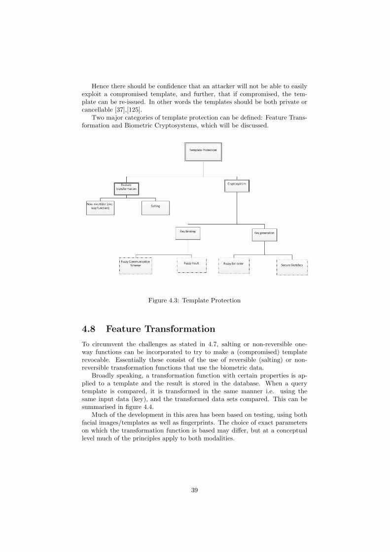
Hence there should be confidence that an attacker will not be able to easilyexploit a compromised template, and further, that if compromised, the tem-plate can be re-issued. In other words the templates should be both private orcancellable [37],[125].
Two major categories of template protection can be defined: Feature Trans-formation and Biometric Cryptosystems, which will be discussed.
Figure 4.3: Template Protection
4.8 Feature Transformation
To circumvent the challenges as stated in 4.7, salting or non-reversible one-way functions can be incorporated to try to make a (compromised) templaterevocable. Essentially these consist of the use of reversible (salting) or non-reversible transformation functions that use the biometric data.
Broadly speaking, a transformation function with certain properties is ap-plied to a template and the result is stored in the database. When a querytemplate is compared, it is transformed in the same manner i.e. using thesame input data (key), and the transformed data sets compared. This can besummarised in figure 4.4.
Much of the development in this area has been based on testing, using bothfacial images/templates as well as fingerprints. The choice of exact parameterson which the transformation function is based may differ, but at a conceptuallevel much of the principles apply to both modalities.
39

Figure 4.4: Authentication Process Using Feature Transformation [80]
4.8.1 Salting
This process involves the use of a transformation function, on the basis that anytransformation is application or transaction dependent. This process incorpo-rates the use of a reversible function, in contrast to the alternative transforma-tion type. Doing so has the added advantage of adding randomness (entropy) tothe biometric system [127]. Generally speaking these transformation functionsuse random data (key, password or other) as input.
Various error detection methods have been used on the basis of extractingcode words from the biometric templates themselves, or derivations of themto be used as hashes [145]. One of the early techniques as used by Davida [37]incorporated binary representations of the input templates, and transformationscarried out and measured against Hamming distances (differing bit sections) toperform matching.
Another example of this was generically proposed in [31]∗∗. This describeda transformation technique where the biometric templates were represented asvarious bits or groups of bits within a data array. The match function dependedon the degree of similarity between 2 templates as compared to others. Withinthat context, it was suggested that a match could be performed specifically byway of comparison with distinct data elements, looking at the Hamming distancebetween them - relative to a threshold - as the basis for a matching score. Oneof the set-ups proposed could involve using data entities within pairs, wherethe first bit represented data, and the second a control bit, used to validate thefirst. With a positive validation, the first data bit would become input to thetransformation function.
As discussed, the perceived advantages of this approach are the qualities ofrevocability and entropy that it imparts. Hence, the FAR is kept low and systemapplication operators or system owners can re-assign templates from previousones. This can be either from the master - or other - templates that are furtherderived within a key hierarchy. Increased privacy could be obtained in the firstinstance, if the master template were transformed as part of the (live) featureextraction process.
∗∗The basic principles on which this depended can be found in 6.5
40

4.8.2 Non-invertible function
These involve the use of transformation functions incorporating a key, but theideal property of the function that should be conveyed is that it is computation-ally difficult (in polynomial time) to reverse, even in the presence of the key.In other words, these effectively share similar properties to a hash function andmay incorporate them. Therefore, if a brute force attack on the key is possible,it would be difficult for an attacker to reverse the transformed template andderive anything meaningful.
One of the first examples of this was as in [125] where non-invertible distor-tions were applied to point patterns within minutiae, based on the perturbationof various features.
A “Bio-Hash” scheme was developed [81], which integrated the use ofrandomised data generated by a token, combined with biometric feature setsderived from an(integrated) wavelet Fourier-Mellin function [143] applied to afingerprint template. This function performed well in terms of error rates andprovided benefit by mitigating the risk of a stolen token.
The disadvantage of this approach is that such techniques introduce lowerintra-class variation, i.e. a lower degree of entropy(discrimination) within thesame template - a week notion of strength for template matching [28]. It istherefore necessary, in order to avoid exploitation by an attacker, that a functionis used that does not produce a high level of variation.
Stonger hashes have been proposed to address this issue, for example thoseusing a transformation function that uses both a standard cryptographic hash(SHA-1 and MD5) and a “robust hash”[140]. In the example of [140], this couldbe done by using a sum of differentially varying Gaussian functions (applicablein this case for match comparisons between differing facial biometric templates).During this process, templates can be transformed using the cryptographic hashfunction and robust algorithm as input, and stored within smart cards. This is apartly effective measure to address the problem of varying input parameters. Inaddition it leaves an attacker with some difficulty in determining the templatedata by analysis of the transformation even in the presence of a card.
The “Bio-Hash” transformation function was reformulated, further ac-counting for the problems of variance in a smart card. This was developed andclaimed to produce negligible error FRRs as well as providing a strong two-factorsolution for biometric template protection [145].
Other approaches have been used with the goal of making transformed fea-ture sets “cancellable”. This concept can be applied to transformation functionson various fingerprint templates (as in [127], where several algorithms were com-pared demonstrating the feasibility of compromising, resistance to brute forceattack, and cancelability - while maintaining performance).
Transformation functions offer some advantages and disadvantages [80]. Salt-ing is useful for key revocability because a user-specific key is used to producemultiple templates from the same user. However, the downside of this approachis the dependence on the use of a key, which if vulnerable could lead to discov-ery and compromise if the transformation function is known (it is reversible).Non-invertible transformations have the distinct advantage that if the key isdiscovered, it is computationally difficult to then reverse the function to derivethe template. If the transformation functions are related to specific users, thenthe natural consequence is that the generated templates and their feature sets
41

will be diverse and revocable. The drawback of such an approach is that it isdifficult to construct a transformation function that appropriately balances thesimilarity between feature sets with a strong notion of irreversibility.
4.9 Biometric Cryptosystems
Biometric cryptosystems are in essence a fusion between between biometrics andcryptography. Early biometric cryptosystems that were developed [149], [138]were used either to generate or protect cryptographic (biometric)keys usingcharacteristic features within biometric templates. However, these cryptosys-tems are also very useful subjects for protecting biometric templates themselves.
The principle of the cryptosystem works on the basis that some informa-tion that is made public or notional “helper data” [8] is stored, alongside thetemplate, for use during transmission. The helper data, as its name suggests,is functionally present in order to perform a match between the stored and en-rolled template. The main quality that the helper data should convey is that itshould be divorced from the feature-specific aspects of the template and com-putationally infeasible to determine (anything else about) the template fromit[80]. This public information is used to derive a secret key (that it shouldnot otherwise reveal), which is used to determine a match score between liveand stored templates, i.e. one that is dependent on key matching. In a strongcryptosystem, it should be computationally infeasible to derive the biometrictemplate from public helper data.
A strong cryptosystem may be of great use in preventing an attacker fromgenerating a successful match score, and crucially, from deriving any meaningfrom it, which would potentially help thwart the various attacks described.Among the more basic methods of this kind, some methods involve simply hidingadditional information (of various kinds). This may include the match score,or any other information for access purposes, including ACLS (as referred to in2.1). However, a more secure suggestion is that information is protected so thatonly on the release of key embedded in the template, would the informationthen be released.
There are 3 main sub-categories of biometric cryptosystem:- key-binding,key-generation [80] and hybrid systems, which will be discussed in turn.
Key Generation:
• The helper data is unprotected and is derived from the stored template.
• A key is generated from the helper data and the biometric feature sets.
In other words, where we have: a template (T), a function (F) and helperdata (H), enrollment will be H =F(T)
Key Binding:In this approach, the helper data is a product of an independent key com-
bined with data from the stored biometric template.
Hybrid Systems:These involve a mixture of the above approaches and/or with transformation.
42

4.9.1 Key Generation
There are 2 main approaches that encompass the methods in which a key can begenerated from a biometric template, which are “secure sketches”and “fuzzyextractors”[41]. Ideally both approaches will address the problem with intra-class variability between fingerprint templates, which should be low. The idealaspects of either key generation function are that they maintain key stability(consistent keys generated regardless of input), whilst keeping the entropy ata high enough level to minimise intra-class variation. There are differences inhow each of these developed approaches achieve these qualities.
A “secure sketch” is a specific function that is probabilistic and outputshelper data that cannot be used to determine the input source. This enables atemplate to be reconstructed where there is a close (rather than exact) matchbetween the live template and stored template, and can lead to a higher FAR,which is not desirable. However, it does address the low level of intra-classvariability.
A “fuzzy extractor” differs from a secure sketch in that it is a cryptographicprimitive that uses template features directly, and processes them using errorcorrection to produce a random key. However, the output keys are stable re-gardless of the input, so that key stability is maintained.
The secure sketch, as in [41], was conceptualised as a product of 3 majormetrics. These were: the differing number of bit positions between the inputand a comparison template (Hamming distance), the size of the entire symmetricdistance between the 2 templates (set difference) and the number of insertionsand deletions (edit difference).
Secure sketches have been studied in fingerprint systems using quantisationon minutiae to derive the secure sketches as digital representations, with reason-ably accurate matching results [17]. This idea has been tested within authen-tication systems fusing both facial and fingerprint-based biometric modalities[139]. As in [139], the issues of “key stability” and “key entropy” are important.These refer, respectively, to the consistency of a single key generated from thesame biometric set and the degree to which multiple keys can be generated.
Such cryptosystems have also been incorporated in hybrid variations [41],[139], an example of which is specified in [132]. In this scheme 2 secure sketcheswere used to analyse handwriting. Other areas have also investigated the use ofmultiple secrets [47] to iteratively nest various secure sketches (for example byencrypting one sketch) in order to prioritise the attibution of lower entropy tovarious secrets.
Since the originally proposed construct in [41], development of secure sketchesis continuing to be reviewed and refined [42]. In [17] it was shown how the securesketch helper can be used as input to form a fuzzy extractor.
4.9.2 Key Binding
Within key binding cryptosystems, key binding involves first generating a key,which is then combined with a template to form helper data and can then bestored in a storage subsystem (i.e. within a PICC) where it may be used tosecure the biometric data. This is different to key generation cryptosystemswhere the key is the final output. Such schemes may also be hybridised, wherethe keys used can be a product of a fuzzy extractor. Similarly, a fuzzy vault (as
43
dicussed below) can be used as a fuzzy extractor as in [41].The main schemes therein are the Fuzzy Commitment Scheme [83] or the
Helper Data Scheme. The Fuzzy Commitment Scheme[83] is a conceptthat was developed based on fuzzy logic [155]. The fundamental principlesbehind this are explained in [80]. Essentially the commitment in this sense isa codeword, and is used to denote the helper data. This provides some level oferror tolerance and therefore increased entropy.
The additional types are Helper Data Schemes or Shielding Functions [92].These involve large amounts of pre-processing or quantisation of data in theenrollment phases, to produce discrete values from within a noisy feature set,which can then be used alongside the key to produce the helper data [147].
Fuzzy Vaults[82] are among the most frequently used key binding schemes.They provide a measure of error tolerance in the presence of noisy data. Thescheme builds on the principles of the Fuzzy Commitment Scheme [83] andworks by the notion that some private information can be bound to a specificdata set or vault. A vault is essentially an “order-invariant” data set, i.e. itdoes not place any of the elements within in an ordered manner.
At enrollment, the template is encrypted with a specific data set in whichthe key is placed or locked. Matching is successful when the similarity of thedata sets is of an acceptable tolerance with respect to a threshold value. Inaddition to being tolerant to errors as in the Helper Data Scheme, they are alsotolerant to any re-ordering in key values (i.e. within the vault). The process bywhich this works is [98]:Enrollment:
• The user to be enrolled (person A) uses an unordered data set DA key ina vault using an unordered set TA
• A selects a polynomial P that encodes a secret key (K).
• A calculates the polynomial projection for elements of TA i.e. P(TA)
• Random noise is added by the use of chaff points with various projectionvalues that differ to P. This is used to derive the helper data V.
Verification :
• Second user B uses a second data set FB .
• If data set FB is sufficiently similar then he can derive K.
However, if FB is not sufficiently similar, B will not be able to locate enoughpoints within the V that corresponds with the polynomial, compounded by therandomness of the chaff data, and therefore derive K.
The main advantage of a key binding system is its tolerance to intra-classvariations (high entropy). [80]. However, because they are error-corrected priorto encoding this can affect the convenience of the system and lead to falsematches. Secondly, these have the disadvantage that they are not application-specific and therefore are not cancellable, unlike transformation functions. More-over, the fact that they are key-dependent means that the keys must be securelyheld.
One of the aspects of concern in a key binding cryptosystem is that variousforms of error correction may be used. This may lead to a degradation in
44

accuracy as the measure by which the key can be retrieved is determined by thesimilarity of the codeword. As a result, the error correction methods must beused alongside sophisticated matching functions, to ensure that there is a goodbalance between key entropy and stability.
Some of drawbacks of these cryptosystems have been highlighted by thepotential availability of attacks, depending on the set up parameters of thesystem.
3 main types of attack have been categorised in this area [133], althoughmainly to the application of fuzzy vaults:
• Record Multiplicity : An attacker can take advantage of multiple en-rolled (genuine) templates being processed for the same particular biomet-ric. Using these templates, they may be able to correlate the data that iscommon within the encoding process that has led to each, enabling themto retrieve the biometric data.
• Surreptitious Key Inversion Attack: This relies on the fact thatonce a key has been obtained from a vault, it is generally used to decryptsomething, and therefore it may be vulnerable to attack at that point,particularly if it remains in cleartext. This could be a problem in a MoCPACS - if a secret is intercepted it may be replayed to the same or al-ternative access point. It is therefore important, that to defend this, thederived secret is protected and that any variability in these secrets is keptto a minimum.
• Blended Substitution attack : In this attack, the attacker modifiesthe template without having any knowledge of the template data and anyrecord data. The attacker can blend a secret key into the template eitherbefore or after encoding (in which case the method of encoding must beknown). This may be caried out on a fuzzy vault if the chaff points aresubstituted. In the MoC PACS scenario, it may be that such attaks wouldbe detected, if an attack involved the (genuine) user being denied access.
Fuzzy vaults may be vulnerable to all of these types of attack, in particularRecord Multiplicity, because of the potential non-randomness of data within avault. The chaff points will potentially allow the substitution attacks if theygreatly exceed the number of genuine biometric points [133]. One potentialsolution proposed to address this is the addition of a further layer of protection- the use of a password as input to a transformation function in order to derivean encryption key. This effectively salts the biometric template, which can thenbe added to the vault [111]. This has the advantage that the vaults cannot belinked without the presence of the secret key as well as knowing the helper dataand having a data set with sufficient similarity to the original template featureset. This is therefore claimed to convey the property of key revocability as well.
4.9.3 Outline of Template Security
As discussed above, there are advantages and disadvantages of each of the aboveapproaches. These can be measured by how well each approach maintains theideal properties of fingerprint templates. Such ideal properties are revocability,diversity, security and performance [97].
45

Certainly, the first two properties may be apparent in feature transformationsystems. However, secrecy is based on knowledge of the key and in the case ofwhere non-reversible, this may impact on the convenience of the system if thefeature sets are not similar to the original. In general, it is a challenge withinthese key generation schemes to find an efficient method that can generate astable key on a per user basis, whilst keeping the entropy high enough thatfalse exceptions do not become a significant issue (impacting on performance).Within the key binding cryptosystems, intra-class variation is also tolerated buteach of the measures requires that the error correction process does not reducethe overall accuracy of the system, which can impact on security. As discussed,attackers can exploit the randomness within some of these schemes.
Poor template security will allow many of the attacks to be blended. Forexample, an attack on a Fuzzy Vault may lead to the secret being realised,leading to a discovery of the match score or biometric template. Although withinthe generic environment of the MoC PACS a card is assumed to be secure, theseattacks become real with the element of collusion from someone with access tothe enrollment system. If we assume that the integrity of another stolen andrevoked card has been put at risk, a new bogus card may be created, and usingone of the 3 attacks as described in 4.9.2, the attacker’s template could becomematched by the system. In addition to the direct attacks on cryptosystems, thisallows some of the attacks as above to be performed, in particulat Hill Climbingor Brute Force attacks.
Some of the hybrid approaches being used may add an additional layer ofsecurity [111]. ††. However, the introduction of a password within such a hybridsystem requires an additional factor on which the security of the system poten-tially rests, which adds further inconvenience within the system [98]. Whilethis may enhance the security, it would certainly have an impact on the designof a PACS system, for which one of the main justifications is the avoidance ofpassword management.
At present these template protection schemes are useful studies and are beingconsidered as to what may constitute good template matching and protectingschemes. However, the research in this area is still young and few of theseimplementations have been incorporated in practice - Fuzzy Extractors havebeen used for key generation [86]. In fact, most of the matching implementationemployed by biometric vendors involve proprietary matching algorithms, someof which may incorporate their own features [80].
††this may also be the case for some multimodal systems such as those in [139], althoughthat is another area beyond the scope of this topic
46

Chapter 5
Summary and Conclusion
5.1 Summary of the Overall Security
Chapter 4 described the main attack points on a biometric system that can beperpetrated against a MoC solution. As has been described, there are variousvulnerability points on the system that may be exploited. The attacks describedrepresent the main low-cost attacks unique to a MoC PACS. Ultimately, whetherthese are successful or not depends on the cost and goals of such a system.
Attack point 1 is one of the most applicable of all of the low-cost attackson this system because it requires the least amount of resources. Many sensorsdo not possess each of the types of liveness detection that have been describedbecause of the multiplying effect on costs when considered on a large scale. Forexample, the TCS1 sensor from UPEK is a relatively low-cost semi-conductorsensor, used by Precise Biometrics [123]. As such it may be susceptible to spoof-ing, a typical example of which is where artificial “gummy” fingers are used incombination with saliva to fool the sensor (see 4.3). Ideally fingerprint scan-ners that measure the dynamic properties of a finger should be used, but thesemay require the use/integration of both complex and expensive components(particularly sensors), and techniques such as multispectral analysis.
As also discussed, integrating some of the protocols needed to secure a con-tactless channel, such as the distance-bounding or challenge-response protocolsthat protect against Brute Force and Hill Climbing attacks, requires reasonablyadvanced microprocessing cards and terminals, as well as APIs that are kept up-to-date with the latest security functionality. This may seem relatively trivial,but it requires a reasonably advanced microprocessing card with large amountsof EEPROM to host such functions and the matching code.
Ensuring that templates are protected is an important aspect of securitywithin such a system, as discussed in 6.4. Proprietary matching solutions havebeen developed which may give rise to insecure implementations, that are even-tually exploited.
5.2 Other Developments with Match on-Card
Presedential directory HSPD-12 [153] referred in 1.1 looked at several objectiveswith the aim of understanding the appropriate level of reliability and security
47

for use within Personal Identity Verification Cards.Various levels of testing (MINEX II tests [6]) have been conducted by the
National Institute of Science and Technology (NIST) in the US,by observingmatching performance when using ISO compliant minutiae. Early tests [61] in-dicate that they perform well (mostly perform matching in under 1 second), butas a result of the variety of matching algorithms concerned there are issue withinteroperability between vendors. Ongoing tests are looking at the feasibilityof core templates of ISO ANSI INICTS 378 type minutiae [7]. This format ac-counts for larger numbers of minutiae and includes a quality check, which wouldbe useful in current MoC implementations.
In addition to the testing being conducted for MoC systems as under theframework of MINEX testing, various other tests are being conducted by NISTto assess the feasibility of MoC within contactless environments [36], in theface of concerns over the insecure channel. The initial tests did show thatwithin a particular operation in the area of physical access control, this could beperformed “within 500 milliseconds without secure messaging”. The outcomeshave not as of yet been published in official standards (FIPS), which indicatesthat there is still some way to go before matching approaches are standardised.
Within scope of the TURBINE project (as referred in 1.1) is the deploymentof an access control MoC solution using a test bed site at Thessaloniki Interna-tional Airport, Greece. This solution aims to regulate access to various accesspoints by airport ground staff. Access control rights and privileges are to bestored on a contactless access card. Some of the research is being conductedin this area within the airport security PACS environments. Of particular rele-vance therein is a study of the relationship between the maximum performanceand key sizes within the Fuzzy Committment Scheme (FCS) as used in tem-plate protection[86]. Another area being researched under this project is therationalisation for solutions incorporating pseudo-identification (PI) data [39]∗.
5.3 Conclusion
PICCs are resource-constrained environments and it is a challenge to integratethe relevant security mechanisms into them (as well as terminal devices) inorder to mitigate against even low-costs attacks against a MoC PACS system,whilst ensuring that performance times are kept very low. In MoC PACS, suchrequirements are essential, but each of the countermeasures described requirean additional cost overhead and there is a potential trade off between cost andconvenience. Ideally, matching times need to be very quick for a MoC PACSimplementation to be effective, whilst ensuring that false acceptances are keptvery low.
Arguably the motivation for such systems comes from areas where high se-curity is a priority, such as in airports or government buildings. In such largeenvironments (or networks of them) there are normally numerous access pointsand staff to consider, so the specific costs of improving each of the individual el-ements of the system multiply as they are purchased on a large scale. Althoughthe various tamper-proof mechanisms within a card have not been explicitlydiscussed within the scope of this project, there is a cost for ensuring that state
∗independent tests appear to show that this approach is also significantly faster whencompared with matching done at the (commonly-used) minutiae-level [38]
48

of the art components and techniques are used to ensure tamper-resistance re-stricts access to them. This is one of the first priorities in MoC systems.
It is probably the case that using fingerprint-based verification on contactlesscards within a PACS does provide a greater level of security than traditionaltwo-factor verification using passwords, when resources are not a limiting factor.However, one of the main complications affecting the security of biometric tem-plates is that standard methods of encryption cannot be used to protect them.Biometric templates do not contain linear information. They are an assortmentof various data extracted from fingerprints, some of which are noisy, and someof which are cross-correlated. All of these aspects complicate how they can beprotected and how the matching process is carried out. This is to the extentthat some of the more advanced ways of protecting a template involve the useof additional data sets (helper data) and passwords in the case of hybrid sys-tems. The latter, which appears to be among the more secure of the templateproection mechanims simply transfers the problem of password managementand key management(one of the key motivators for using biometrics in prefer-ence) onto biometric verification schemes. This typifies how two-factor systeminvolving the use of biometrics may not necessarily present a major advantageover passwords. There are, of course, additional administrative costs associatedwith this (in terms of how enrolled biometric templates sets are assigned orrevoked). Consequently, there is still some way to go before more firm cases aremade for why biometric credentials should replace PINs or passwords in twofactor deployments using tokens, as defending against even the low-cost attacksavailable to insiders is potentially costly and challenging.
As the components of smart card microcontrollers (including state-of-the-artRISC controllers) and sensor technologies begin to fall, as well as improvementsmade to biometric cryptosystems, it is likely that MoC implementations willbe more frequently used within PACS environments. Testing of both standard-ised and vendor-proprietary minutiae matching algorithms in relation to speed,security and FAR/FRR rates is continuing. If the results of such tests lead togreater interoperability between vendors, more investment may be made in suchsolutions - one of the major stimuli for eventual roll-out.
5.4 Summary of Objectives
The objectives of this project can be re-summarised:
• To discuss the main resource constraints on microprocessingproximity cards and how this can lead to vulnerabilities.
• To discuss a range of low-cost attacks that are applicable to theenvironment being considered.
• To discuss the various countermeasures to the above attacks andpotential ways to secure templates.
• To evaluate the potential security advantages or disadvantagesof MoC implementations.
These were satisfied as follows:
49

• Chapters 1 and 2 provided a framework for the main concepts behindon-card verification. This included some of the standards that providedetailed requirements that restrict the resources on a PICC. Chapter 3discusses the actual resource constraints, which provides the basis for ageneric environment against which applicable attacks are discussed in inChapter 4. This includes how the cheap sensor components can limitspoof detection and how communication protocols depend on what can befactored into the API of a card. This satisfies objective 1.
• A range of potential attacks applicable to the MoC system were discussedin Chapter 4 which satisfies objective 2.
• The various countermeasures were discussed within the context of theattacks and section on Template Security within chapter 4, satisfying ob-jective 3.
• The security advantages and disadvantages of a MoC PAC were bothinferred in the context of the attacks and countermeasures and were sum-marised (as in the summary of the overall security - see 5.1 and discussionof the other areas of development within Match on-Card as in 5.2), as wellas in the final conclusion.
50
Chapter 6
Appendix
The following are provided to assist with some of the main concepts in mainbody of this project.
6.1 Carrier Channel Modification
For type A interfaced proximity systems, between the PCD and the PICC,Amplitude Shift Keying (ASK) is used as the carrier modulation procedureand with Modified Miller Coding as the data coding in the baseband. ASKeffectively alters the amplitude to a specific level to represent a data value,at a binary signal level. Modified Miller Coding (To use the definition in theISO/IEC 14443 standard[2])is a coding procedure where “a logic level during abit-duration is represented by the position of a pulse”, in other words, withina bit-duration (bit-period), a transition is represented by a very short negativepulse.
In the back channel between a PICC and a PCD, load modulation is usedwith On/Off keying (OOK), a form of ASK known as Manchester Coding. Inthis case a binary 1 digit is replaced by a negative (high to low) transition ina half-bit period (middle of a bit period) and a binary 0 digit by an upwards(positive) transition.
51

6.2 Anticollision
Anticollision mechanisms are specified under ISO/IEC 14443-3[3]. For morespecific details on data representation, signalling and anticollision, please referto chapter 6 of [48] and pages 312-315 of [103], which provide explain theseaspects at a more granular level. In context of this project, these would allapply to type A PICCs as defined within ISO/IEC 14443-2 [3] standard.
The process of anticollision will be briefly can be briefly summarised asfollows:
A PCD will intermittently send out polling requests to detect the presence ofa specific PICC. Prior to entry into the interrogation zone, a PICC is poweredoff, but when entering the interrogation zone if a PCD a PICC is poweredup via proximity coupling as described in section 2.5. The token is then sitsin a READY state and on receiving a response from the PICC will becomeaware of the PICCs presence. To avoid collision the communications protocolmakes use of the SELECT command, which is used alongside a designatedportion of a unique card identifier (CID) sent by the PICC, and compared withreference (search) data held by the PCD. This is compared with the (sameportion-length) CID information provided by any additional PICCs within theinterrogation field. Any bit-level collisions between PICC identifiers will bedetected and notioned by the PCD as to where within the position of an identifierany collision has occurred. The PCD will adjust its search and send the resultsto the PICCs, the correct of which will send further identifier information. Thisoccurs on an interative basis until eventually the PICC of interest is identifiedand an acknolwledgement message sent to the PCD at which point the PICCwill switch to an ACTIVE state.
52

6.3 Data transmission
The data transmisson between a PCD and PICC device is defined within ISO14443-4 [4] which acts at the equivalent of the OSI transport layer. This defineshow the data is arranged into frames and blocks of data and correctly addressedto a PICC according to its CID, how data blocks may be chained together (ifabove the specified frame sizes used by a PICC), how timing of transmissionsis monitored and the control of transmission errors.
Essentially, once a PICC is in its ACTIVE state, it awaits further commandsfrom the PCD and is set up within a master-slave configuration. The frame islogically divided into 3 main sections (fields).
Within the Protocol Control Byte (PCB) field therein, are 3 types of logicaldata blocks, : the I block, R block and S block. These blocks are used fordata transmission of information, control of transmission errors and additionalcontrol/status information respectively. Of significance to data transfer is the Iblock, which encodes the data blocks for use within the application layer above.
The information INF field is used to contain information from the the I andS blocks, and crucially the former holds application level data as defined byApplication Data Units (APDUs).
The terminal field within the frame consists of a CRC (error detection code)that is used for error checking.
53

6.4 Challenge-response Protocol
Figure 6.1: Challenge-Response Protocol [28]
54

Figure 6.2: Application Specific Transformation Function [31]
6.5 Dependencies for the Application SpecificTransformation Function Proposed by Cam-bier
55

Bibliography
[1] ISO/IEC 14443. Identification cards Contactless integrated circuit cardsProximity cards.
[2] ISO/IEC 14443-2. Identification cards Contactless integrated circuit(s)cards - Proximity cards Part 2: Radio frequency power and signalinterface. 2001.
[3] ISO/IEC 14443-3. Identification cards Contactless integrated circuit(s)cards - Proximity Cards Part 3: Initialization and anticollision. 2001.
[4] ISO/IEC 14443-4. Identification cards - Contactless integrated circuitcards - Proximity cards – Part 4: Transmission protocol. 2008.
[5] ISO/IEC 19784. Information technology - Biometric applicationprogramming interface - Part 2: Biometric archive function providerinterface.
[6] ISO/IEC 19794-2. Biometric data interchange formats - Part 2 - Fingerminutiae data. 2005.
[7] ANSI INCITS 378-2004. Information technology - Finger Minutiae Formatfor Data Interchange.
[8] N.Menon A. Vetro. Biometric system security - tutorial. In At 2ndInternational Conference on Biometrics, South Korea, 2007.
[9] Gil Abramovich, Meena Ganesh, Kevin Harding, Swaminathan Man-ickam, Joseph Czechowski, Xinghua Wang, and Arun Vemury. A spoofdetection method for contactless fingerprint collection utilizing spectrumand polarization diversity. volume 7680, page 768005. SPIE, 2010.
[10] A. Adler. Images can be regenerated from quantized biometric matchscore data. volume 1, pages 469 – 472 Vol.1, may. 2004.
[11] M.M.A. Allah. A fast and memory efficient approach for fingerprint au-thentication system. In Advanced Video and Signal Based Surveillance,2005. AVSS 2005. IEEE Conference on, pages 259 – 263, 15-16 2005.
[12] Smart Card Alliance. Contactless Technology for Secure Physical Access:Technology and Standards Choices. Publication Number: ID-02002, 2002.
[13] Smart Card Alliance. Rf-enabled applications and technology- comparing and contrasting rfid and rf-enabled smart cards.www.smartcardalliance.org - accessed 28/07/08, 2008.
56

[14] R. Anderson, M. Bond, J. Clulow, and S. Skorobogatov. Cryptographicprocessors-a survey. Proceedings of the IEEE, 94(2):357 –369, feb. 2006.
[15] Ross Anderson, Markus Kuhn, and England U. S. A. Tamper resistance -a cautionary note. In In Proceedings of the Second Usenix Workshop onElectronic Commerce, pages 1–11, 1996.
[16] A. Antonelli, R. Cappelli, D. Maio, and D. Maltoni. Fake finger detectionby skin distortion analysis. Information Forensics and Security, IEEETransactions on, 1(3):360 –373, sep. 2006.
[17] Arathi Arakala, Jason Jeffers, and K. Horadam. Fuzzy extractors forminutiae-based fingerprint authentication. In Seong-Whan Lee and StanLi, editors, Advances in Biometrics, volume 4642 of Lecture Notes inComputer Science, pages 760–769. Springer Berlin / Heidelberg, 2007.
[18] W.J. Babler. Embryologic development of epidermal ridges and their con-figurations. Birth Defects: Original Article Series, 27(2):95–112, 1991.
[19] Denis Baldisserra, Annalisa Franco, Dario Maio, and Davide Maltoni.Fake fingerprint detection by odor analysis ,. In David Zhang and AnilJain, editors, Advances in Biometrics, volume 3832 of Lecture Notes inComputer Science, pages 265–272. Springer Berlin / Heidelberg, 2005.
[20] Luca Benini, Alberto Macii, Enrico Macii, Elvira Omerbegovic, FabrizioPro, and Massimo Poncino. Energy-aware design techniques for differ-ential power analysis protection. In DAC ’03: Proceedings of the 40thconference on Design automation, pages 36–41, New York, NY, USA,2003. ACM.
[21] Christer Bergman. Match-on-card for secure and scalable biometric au-thentication. Advances in Biometrics Sensors, Algorithms and Systems,2008.
[22] Istvn Berta and Zoltn Mann. Smart cards - present and future.Hradstechnika, Journal on C5, 12 2000.
[23] Abhilasha Bhargav-Spantzel, Anna Squicciarini, and Elisa Bertino. Pri-vacy preserving multi-factor authentication with biometrics. pages 63–72,2006.
[24] Precise Biometrics. Precise bioaccess 200 - product description.www.precisebiometrics.com - accessed 28/06/10.
[25] Precise Biometrics. Precise biomatch smart card 4 product description.www.precisebiometrics.com - accessed 28/06/10.
[26] Errol A. Blake. The management of access controls/biometrics in organi-zations. In InfoSecCD ’06: Proceedings of the 3rd annual conference onInformation security curriculum development, pages 179–183, New York,NY, USA, 2006. ACM.
57

[27] Ruud Bolle and Sharath Pankanti. Biometrics, Personal Identification inNetworked Society: Personal Identification in Networked Society. KluwerAcademic Publishers, Norwell, MA, USA, 1998. Arcticle: Pages 12 - 49is ”Introduction to Biometrics”.
[28] Ruud M. Bolle, Jonathan H. Connell, and Nalini K. Ratha. Biometricperils and patches. Pattern Recognition, 35(12):2727 – 2738, 2002.
[29] Stefan Brands and David Chaum. Distance-bounding protocols. In TorHelleseth, editor, Advances in Cryptology EUROCRYPT 93, volume 765of Lecture Notes in Computer Science, pages 344–359. Springer Berlin /Heidelberg, 1994.
[30] Julien Bringer, Herv Chabanne, Tom Kevenaar, and Bruno Kindarji. Ex-tending match-on-card to local biometric identification. In Julian Fier-rez, Javier Ortega-Garcia, Anna Esposito, Andrzej Drygajlo, and Mar-cos Faundez-Zanuy, editors, Biometric ID Management and MultimodalCommunication, volume 5707 of Lecture Notes in Computer Science,pages 178–186. Springer Berlin / Heidelberg, 2009.
[31] James L Cambier. Application-specific biometric templates. IEEEWorkshop on Automatic Identification Advanced Technologies,Tarrytown, NY, pages 167–171, 2002.
[32] CESG. Biometric device protection profile (bdpp) - draft issue 0.82. Tech-nical report, CESG, 2001.
[33] Heeseung Choi, Raechoong Kang, Kyoungtaek Choi, Andrew Teoh BengJin, and Jaihie Kim. Fake-fingerprint detection using multiple static fea-tures. Optical Engineering, 48(4):047202, 2009.
[34] S. A. Cole. What counts for identity? Fingerprint Whorld, 27, No.103:7–35, 2001.
[35] Nicolas T. Courtois, Karsten Nohl, and Sean O’Neil. Algebraic attacks onthe crypto-1 stream cipher in mifare classic and oyster cards. CryptologyePrint Archive, Report 2008/166, 2008.
[36] Philip Lee William MacGregor Ketan Mehta David Cooper, Hung Dang.Secure biometric match-on-card feasibility report. NIST, 2007.
[37] G.I. Davida, Y. Frankel, and B.J. Matt. On enabling secure applicationsthrough off-line biometric identification. pages 148 –157, may. 1998.
[38] Patrick Bours Davrondzhon Gafurov, Bian Yang and Christoph Busch.Independent performance evaluation of biometric systems. NIST, 2010.
[39] N. Delvaux, H. Chabanne, J. Bringer, B. Kindarji, P. Lindeberg,J. Midgren, J. Breebaart, T. Akkermans, M. van der Veen, R. Veld-huis, E. Kindt, K. Simoens, C. Busch, P. Bours, D. Gafurov, Bian Yang,J. Stern, C. Rust, B. Cucinelli, and D. Skepastianos. Pseudo identitiesbased on fingerprint characteristics. pages 1063 –1068, aug. 2008.
58

[40] Damien Dessimoz, Jonas Richiardi, Prof Christophe, Champod Dr, andAndrzej Drygajlo. Multimodal Biometrics for Identity Documents 1. EcolePolytechnique Federale De Lausanne, Universite de Lausanne, 2006.
[41] Yevgeniy Dodis, Rafail Ostrovsky, Leonid Reyzin, and Adam Smith.Fuzzy extractors: How to generate strong keys from biometrics and othernoisy data. pages 523–540. Springer-Verlag, 2004.
[42] Yevgeniy Dodis, Rafail Ostrovsky, Leonid Reyzin, and Adam Smith.Fuzzy extractors: How to generate strong keys from biometrics and othernoisy data. SIAM J. Comput., 38(1):97–139, 2008.
[43] David Engberg. Secure Access Control with Government ContactlessCards. Tech Republic, 2005.
[44] Byungkwan Park et al. Impact of embedding scenarios on the smart card-based fingerprint verification. In WISA, pages 110–120. Springer-VerlagNew York, Inc., 2006.
[45] David Wills et al. Six Biometric Devices Point The Finger At Security.http://www.networkcomputing.com/910/910r14.html accessed 14/06/10,1998.
[46] C.H. Fancher. In your pocket: smartcards. Spectrum, IEEE, 34(2):47 –53,feb 1997.
[47] Chengfang Fang, Qiming Li, and Ee-Chien Chang. Secure sketch formultiple secrets. In Jianying Zhou and Moti Yung, editors, AppliedCryptography and Network Security, volume 6123 of Lecture Notes inComputer Science, pages 367–383. Springer Berlin / Heidelberg, 2010.
[48] Klaus Finkenzeller. RFID Handbook: Fundamentals and Applications inContactless Smart Cards and Identification. John Wiley & Sons, Inc.,New York, NY, USA, 2003.
[49] Udo Flohr. The smart card invasion. Byte 23, 1988.
[50] M. Fons, F. Fons, E. Canto, and M. Lopez. Hardware-software co-designof a fingerprint matcher on card. Electro/information Technology, 2006IEEE International Conference on, pages 113–118, May 2006.
[51] European Community’s7th Framework Programme (FP7/2007-2013).Trusted revocable biometric identities. http://www.turbine-project.eu.
[52] Annalisa Franco and Davide Maltoni. Fingerprint synthesis and spoofdetection. In Nalini Ratha and Venu Govindaraju, editors, Advances inBiometrics, pages 385–406. Springer London, 2008.
[53] Michalis D. Galanis, Gregory Dimitroulakos, and Costas E. Goutis. Per-formance and energy consumption improvements in microprocessor sys-tems utilizing a coprocessor data-path. J. Signal Process. Syst., 50(2):179–200, 2008.
59

[54] Javier Galbally, Raffaele Cappelli, Alessandra Lumini, GuillermoGonzalez-de Rivera, Davide Maltoni, Julian Fierrez, Javier Ortega-Garcia,and Dario Maio. An evaluation of direct attacks using fake fingers gener-ated from iso templates. Pattern Recogn. Lett., 31(8):725–732, 2010.
[55] Gemalto. .net v2+ card. www.gemalto.com accessed 15.06.10.
[56] Bill Glover and Himanshu Bhatt. RFID Essentials (Theory in Practice(O’Reilly)). O’Reilly Media, Inc., 2006.
[57] Dieter Gollmann. Computer Security. John Wiley and Sons, Chichester,West Sussex, second edition, 2006.
[58] L. Gong. Variations on the themes of message freshness and replay-or thedifficulty in devising formal methods to analyze cryptographic protocols.pages 131 –136, jun. 1993.
[59] Joe Grand. Practical secure hardware design for embedded systems joegrand * grand idea studio, inc., 2004.
[60] A. Grebene and H. Camenzind. Phase locking as a new approach for tunedintegrated circuits. In Solid-State Circuits Conference. Digest of TechnicalPapers. 1969 IEEE Internationa, volume XII, pages 100 – 101, feb 1969.
[61] P. Grother and W. Salamon. Minex ii performance of fingerprint match-on-card algorithms evaluation plan. NIST Interagency Report 7485, 2007.
[62] Smart Card Group. Smart card tutorial. http://www.smartcard.co.uk/,September 1992.
[63] Gerhard Hancke. A practical relay attack on iso 14443 proximity cards.2005.
[64] G.P. Hancke and M.G. Kuhn. An rfid distance bounding protocol. pages67 – 73, sep. 2005.
[65] Helena Handschuh and Pascal Paillier. Smart card crypto-coprocessorsfor public-key cryptography. In CARDIS, pages 372–379, 1998.
[66] C.J. Hill. Risk of masquerade arising from the storage of biometrics. BScHonours Thesis, Department of Computer Science, Australian NationalUniversity, 2001.
[67] Richard Hopkins. An Introduction to Biometrics and Large Scale CivilianIdentification. International review of law, computers and technology; vol.13 No 3., 1999.
[68] D. Husemann. The smart card: don’t leave home without it. Concurrency,IEEE, 7(2):24–27, Apr-Jun 1999.
[69] INCITS. Incits b10 identification cards and related devices, 2008 annualreport. http://www.incits.org, 2008.
[70] ISO/IEC. ISO/IEC 7816: Identification cards – Integrated Cicuit Cards- Part 3: Cards with contacts Electrical interface and transmissionprotocols.
60

[71] ISO/IEC. ISO/IEC 7810: Identification cards – Part 1: Physicalcharacteristics. 1995.
[72] ISO/IEC. ISO/IEC 10181 - Part 3 - Information technology - OpenSystems Interconnection - Security frameworks for open systems: Accesscontrol framework Technologies. 1996.
[73] ISO/IEC. ISO/IEC 10373-1:2006. 2006.
[74] A.K. Jain, Lin Hong, S. Pankanti, and R. Bolle. An identity-authentication system using fingerprints. Proceedings of the IEEE,85(9):1365–1388, Sep 1997.
[75] A.K. Jain, A. Ross, and S. Pankanti. Biometrics: a tool for informa-tion security. Information Forensics and Security, IEEE Transactions on,1(2):125–143, June 2006.
[76] A.K. Jain, A. Ross, and S. Prabhakar. An introduction to biometric recog-nition. Circuits and Systems for Video Technology, IEEE Transactions on,14(1):4–20, Jan. 2004.
[77] Anil Jain, Lin Hong, and Sharath Pankanti. Biometric identification.Commun. ACM, 43(2):90–98, 2000. General - description of biometricmodalities.
[78] Anil K. Jain, Patrick Flynn, and Arun A. Ross. Handbook of Biometrics.Springer-Verlag New York, Inc., Secaucus, NJ, USA, 2007.
[79] Anil K. Jain and David Maltoni. Handbook of Fingerprint Recognition.Springer-Verlag New York, Inc., Secaucus, NJ, USA, 2003.
[80] Anil K. Jain, Karthik Nandakumar, and Abhishek Nagar. Biometric tem-plate security. EURASIP J. Adv. Signal Process, 8(2):1–17, 2008.
[81] Andrew Teoh Beng Jin, David Ngo Chek Ling, and Alwyn Goh. Biohash-ing: two factor authentication featuring fingerprint data and tokenisedrandom number. Pattern Recognition, 37(11):2245 – 2255, 2004.
[82] A. Juels and M. Sudan. A fuzzy vault scheme. page 408, 2002.
[83] Ari Juels and Martin Wattenberg. A fuzzy commitment scheme. pages28–36. ACM Press, 1999.
[84] European Commission Freedom Justice and Security. Biometrics at thefrontiers: Assessing the impact on society for the european parliamentcommittee on citizens’ freedoms and rights, justice and home affairs (libe).http://ec.europa.eu/, 2005.
[85] Konstantinos Markanronakis Keith Mayes. On the potential of high den-sity smart cards. Elseivier Information Security Technical Report, 3, 2006.
[86] Emile J. C. Kelkboom, Jeroen Breebaart, Ileana Buhan, and RaymondN. J. Veldhuis. Analytical template protection performance and maximumkey size given a gaussian-modeled biometric source. volume 7667, page76670D. SPIE, 2010.
61

[87] Fred Piper Kenneth G. Paterson and Matt Robshaw. Smart cards and theassociated infrastructure problem. Information Security Technical Report,7(3):20–29, 2002.
[88] Daniel V. Klein. ’foiling the cracker’ – a survey of, and improvements to,password security. In Proceedings of the second USENIX Workshop onSecurity, pages 5–14, Summer 1990.
[89] Gerhard Koning Gans, Jaap-Henk Hoepman, and Flavio D. Garcia. Apractical attack on the mifare classic. In CARDIS ’08: Proceedingsof the 8th IFIP WG 8.8/11.2 international conference on Smart CardResearch and Advanced Applications, pages 267–282, Berlin, Heidelberg,2008. Springer-Verlag.
[90] Suhas A Desaiand D. B. Kulkarni. Rfid with bio-smart card in linux,white paper. Technical report, Walchand College of Engineering, 2005.
[91] Kwok-yan Lam and Dieter Gollmann. Freshness assurance of authenti-cation protocols. In Yves Deswarte, Grard Eizenberg, and Jean-JacquesQuisquater, editors, Computer Security ESORICS 92, volume 648 ofLecture Notes in Computer Science, pages 259–271. Springer Berlin /Heidelberg, 1992.
[92] Jean-Paul Linnartz and Pim Tuyls. New shielding functions to en-hance privacy and prevent misuse of biometric templates. In AVBPA’03:Proceedings of the 4th international conference on Audio- and video-basedbiometric person authentication, pages 393–402, Berlin, Heidelberg, 2003.Springer-Verlag.
[93] Peter-Michael Ziegler Lisa Thalheim, Jan Krissler. Bodycheck: Biometrics defeated. Reprinted with permission from c’tMagazine, translated from the German by Robert W. Smith -http://www.heise.de/ct/english/02/11/114, June 2002.
[94] Tobias Lohmann, Matthias Schneider, and Christoph Ruland. Analysis ofpower constraints for cryptographic algorithms in mid-cost rfid tags. InCARDIS, pages 278–288, 2006.
[95] Jean-Franois Mainguet. Fingerprint fake detection. In Stan Z. Li andAnil Jain, editors, Encyclopedia of Biometrics, pages 458–465. SpringerUS, 2009.
[96] D. Maio, D. Maltoni, R. Cappelli, J.L. Wayman, and A.K. Jain. Fvc2002:Second fingerprint verification competition. Pattern Recognition, 2002.Proceedings. 16th International Conference on, 3:811–814 vol.3, 2002.
[97] D. Maltoni, D. Maio, A.K. Jain, and S. Prabhakar. Handbook ofFingerprint Recognition. Springer-Verlag, 2003.
[98] Davide Maltoni, Dario Maio, Anil K. Jain, and Salil Prabhakar. Securingfingerprint systems. In Handbook of Fingerprint Recognition, pages 371–416. Springer London, 2009.
62
[99] A. J. Mansfield and J. L. Wayman. Best practices in testing and reportingperformance of biometric devices (v2.1). Technical report, CESG, 2002.
[100] Konstantinos Markantonakis. Is the performance of smart card crypto-graphic functions the real bottleneck? In Sec ’01: Proceedings of the 16thinternational conference on Information security: Trusted information,pages 77–91, Norwell, MA, USA, 2001. Kluwer Academic Publishers.
[101] M. Martinez-Diaz, J. Fierrez-Aguilar, F. Alonso-Fernandez, J. Ortega-Garcia, and J.A. Siguenza. Hill-climbing and brute-force attacks onbiometric systems: A case study in match-on-card fingerprint verifica-tion. Carnahan Conferences Security Technology, Proceedings 2006 40thAnnual IEEE International, pages 151–159, Oct. 2006.
[102] Tsutomu Matsumoto, Hiroyuki Matsumoto, Koji Yamada, and SatoshiHoshino. Impact of artificial ”gummy” fingers on fingerprint systems.volume 4677, pages 275–289. SPIE, 2002.
[103] Keith Mayes and Konstantinos Markantonakis. Smart Cards, Tokens,Security and Applications. Springer, 2008.
[104] Alfred J. Menezes, Scott A. Vanstone, and Paul C. Van Oorschot.Handbook of Applied Cryptography. CRC Press, Inc., Boca Raton, FL,USA, 1996.
[105] B. Miller. Vital signs of identity [biometrics]. Spectrum, IEEE, 31(2):22–30, Feb 1994.
[106] A. Mitrokotsa, C. Dimitrakakis, P. Peris-Lopez, and J.C. Hernandez-Castro. Reid et al.’s distance bounding protocol and mafia fraud attacksover noisy channels. Communications Letters, IEEE, 14(2):121 –123, feb.2010.
[107] Y.S. Moon, J.S. Chen, K.C. Chan, K. So, and K.C. Woo. Wavelet basedfingerprint liveness detection. Electronics Letters, 41(20):1112 – 1113, sep.2005.
[108] Y.S. Moon, H.C. Ho, and K.L. Ng. A secure card system with biometricscapability. Electrical and Computer Engineering, 1999 IEEE CanadianConference on, 1:261–266 vol.1, 1999.
[109] Y.S. Moon, H.C. Ho, K.L. Ng, S.F. Wan, and S.T. Wong. Collaborativefingerprint authentication by smart card and a trusted host. Electrical andComputer Engineering, 2000 Canadian Conference on, 1:108–112 vol.1,2000.
[110] David Naccache and David M’Ra. Arithmetic co-processors for public-keycryptography: The state of the art. P. H. Hartel P. Paradinas and J.-J.Quisquater, 1996.
[111] Karthik Nandakumar, Abhishek Nagar, and Anil Jain. Hardening finger-print fuzzy vault using password. In Seong-Whan Lee and Stan Li, edi-tors, Advances in Biometrics, volume 4642 of Lecture Notes in ComputerScience, pages 927–937. Springer Berlin / Heidelberg, 2007.
63
[112] Garth Nash. Phase-locked loop design fundamentals. Freescale Semicon-ductor, 2006.
[113] Roger M. Needham and Michael D. Schroeder. Using encryption for au-thentication in large networks of computers. Commun. ACM, 21(12):993–999, 1978.
[114] Kristin A. Nixon and Robert K. Rowe. Multispectral fingerprint imagingfor spoof detection. volume 5779, pages 214–225. SPIE, 2005.
[115] NXP. Security of mifare classic. www.mifare.net - as accessed 23/11/09.
[116] NXP. Nxp p5cd036 short form specification, 2004.
[117] U.S Department of Defense. Common Access Card. www.cac.mil - Ac-cessed 04/07/10.
[118] General Services Administration Office of Governmentwide Policy &Smart Card IAB. Government Smartcard Handbook. 2004.
[119] L. O’Gorman. Comparing passwords, tokens, and biometrics for userauthentication. Proceedings of the IEEE, 91(12):2019–2020, Dec 2003.
[120] Michael Osborne and Nalini K. Ratha. A jc-bioapi compliant smart cardwith biometrics for secure access control. In AVBPA, pages 903–910, 2003.
[121] Sharath Pankanti, Salil Prabhakar, and Anil K. Jain. On the individualityof fingerprints. IEEE Trans. Pattern Anal. Mach. Intell., 24(8):1010–1025,2002.
[122] Zeljka Pozgaj. Smart card in biometric authentication. www.foi.hr ac-cessed 25/07/08, 2007.
[123] UPEC TCS1 product sheet., editor. UPEK FIPS 201 Compliant SiliconFingerprint Sensor. www.upek.com - accessed 27/06/10.
[124] Wolfgang Rankl and Wolfgang Effing. Smart Card Handbook. John Wileyand Sons, Chichester, West Sussex, third edition, 2003.
[125] N. K. Ratha, J. H. Connell, and R. M. Bolle. Enhancing security and pri-vacy in biometrics-based authentication systems. IBM Systems Journal,40(3):614 –634, 2001.
[126] Nalini K. Ratha, Jonathan H. Connell, and Ruud M. Bolle. An analysisof minutiae matching strength. In AVBPA ’01: Proceedings of the ThirdInternational Conference on Audio- and Video-Based Biometric PersonAuthentication, pages 223–228, London, UK, 2001. Springer-Verlag.
[127] N.K. Ratha, S. Chikkerur, J.H. Connell, and R.M. Bolle. Generating can-celable fingerprint templates. Pattern Analysis and Machine Intelligence,IEEE Transactions on, 29(4):561 –572, apr. 2007.
[128] N.K. Ratha, K. Karu, Shaoyun Chen, and A.K. Jain. A real-time matchingsystem for large fingerprint databases. Pattern Analysis and MachineIntelligence, IEEE Transactions on, 18(8):799–813, Aug 1996.
64
[129] Jason Reid, Juan M. Gonzalez Nieto, Tee Tang, and Bouchra Senadji.Detecting relay attacks with timing-based protocols. In ASIACCS ’07:Proceedings of the 2nd ACM symposium on Information, computer andcommunications security, pages 204–213, New York, NY, USA, 2007.ACM.
[130] Sagem. Morphoaccess 120 piv product sheet. Available fromhttps://www.biometric-terminals.com/site/presse/MA500.pdf accessed05/07/10.
[131] Marie Sandstrm. Liveness detection in fingerprint recognition systems,2004.
[132] T. Scheidat, C. Vielhauer, and J. Dittmann. Biometric hash generationand user authentication based on handwriting using secure sketches. pages89 –94, sep. 2009.
[133] W.J. Scheirer and T.E. Boult. Cracking fuzzy vaults and biometric en-cryption. pages 1 –6, sep. 2007.
[134] J.K. Schneider and D.C. Wobschall. Live scan fingerprint imagery usinghigh resolution c-scan ultrasonography. pages 88 –95, oct. 1991.
[135] Bruce Schneier. Inside risks: the uses and abuses of biometrics. Commun.ACM, 42(8):136, 1999.
[136] SecureIDNews.com+. ”u.s. department of defense test biometrics on con-tact and contactless military ids”. www.secureidnews.com, 2004.
[137] C Soutar. Biometric system security. The Silicon Trust Quarterly Report,01:46–49, 2002.
[138] Colin Soutar, Danny Roberge, Alex Stoianov, Rene Gilroy, and Bhagavat-ula Vijaya Kumar. Biometric encryption using image processing. volume3314, pages 178–188. SPIE, 1998.
[139] Yagiz Sutcu, Qiming Li, and Nasir Memon. Secure biometric templatesfrom fingerprint-face features. In in Proceedings of CVPR Workshop onBiometrics, 2007.
[140] Yagiz Sutcu, Husrev Taha Sencar, and Nasir Memon. A secure biometricauthentication scheme based on robust hashing. In MM&Sec ’05:Proceedings of the 7th workshop on Multimedia and security, pages 111–116, New York, NY, USA, 2005. ACM.
[141] M. Tartagni and R. Guerrieri. A fingerprint sensor based on the feed-back capacitive sensing scheme. Solid-State Circuits, IEEE Journal of,33(1):133 –142, jan. 1998.
[142] Secure Matrix Technologies. Rfid vs contactless smart cards - an unendingdebate. http://securematrixtec.com, 2006.
[143] A.B.J. Teoh, D.C.L. Ngo, and O.T. Song. An efficient fingerprint verifi-cation system using integrated wavelet and fourier-mellin invariant trans-form. IVC, 22(6):503–513, June 2004.
65

[144] Andrew B.J. Teoh, Alwyn Goh, and David C.L. Ngo. Random multi-space quantization as an analytic mechanism for biohashing of biometricand random identity inputs. IEEE Transactions on Pattern Analysis andMachine Intelligence, 28:1892–1901, 2006.
[145] Andrew B.J. Teoh, Yip Wai Kuan, and Sangyoun Lee. Cancellable bio-metrics and annotations on biohash. Pattern Recognition, 41(6):2034 –2044, 2008.
[146] Xifeng Tong, Jianhua Huang, Xianglong Tang, and Daming Shi. Fin-gerprint minutiae matching using the adjacent feature vector. PatternRecogn. Lett., 26(9):1337–1345, 2005.
[147] Pim Tuyls, Anton Akkermans, Tom Kevenaar, Geert-Jan Schrijen, AskerBazen, and Raimond Veldhuis. Practical biometric authentication withtemplate protection. In Takeo Kanade, Anil Jain, and Nalini Ratha,editors, Audio- and Video-Based Biometric Person Authentication, vol-ume 3546 of Lecture Notes in Computer Science, pages 436–446. SpringerBerlin / Heidelberg, 2005.
[148] Rainer Plaga Ulrike Korte. Cryptographic protection of biometric tem-plates - chance, challenges and applications, pp 33-46. In BIOSIG2007: Biometrics and Electronic Signatures Proceedings of the SpecialInterest Group on Biometrics and Electronic Signatures 12.-13. July 2007,Darmstadt, Germany, 2007.
[149] U. Uludag, S. Pankanti, S. Prabhakar, and A.K. Jain. Biometric cryp-tosystems: issues and challenges. Proceedings of the IEEE, 92(6):948 –960, jun. 2004.
[150] Umut Uludag and Anil K. Jain. Attacks on biometric systems: a casestudy in fingerprints. volume 5306, pages 622–633. SPIE, 2004.
[151] Ton van der Putte and Jeroen Keuning. Biometrical fingerprint recogni-tion: don’t get your fingers burned. In Proceedings of the fourth workingconference on smart card research and advanced applications on Smartcard research and advanced applications, pages 289–303, Norwell, MA,USA, 2001. Kluwer Academic Publishers.
[152] J.L. Wayman. Error rate equations for the general biometric system.Robotics & Automation Magazine, IEEE, 6(1):35–48, Mar 1999.
[153] The Whitehouse Website. Homeland security presidential directive/hspd-12. http://www.whitehouse.gov, 2004.
[154] Neil Yager and Adnan Amin. Fingerprint verification based on minutiaefeatures: a review. Pattern Anal. Appl., 7(1):94–113, 2004.
[155] R. R. Yager, S. Ovchinnikov, R. M. Tong, and H. T. Nguyen, editors.Fuzzy sets and applications. Wiley-Interscience, New York, NY, USA,1987.
66