dispersible transmitting antenna vlf/lf ... circuit two element paran antenna 57 40 three element...
TRANSCRIPT

DISPERSIBLE TRANSMITTING ANTENNA
VLF/LF INVESTIGATION
Homer A. Ray, Jr.
Continental Electronics Mfg. Co.
Approved for public release;distribution unlimited.

FOREWORD
The work covered in this report was accoplished by Continental,Electronics %anufacturing Company, P. 0. Box 17040, Dallas, TX under Con-tract F30602-T1-C-O010, Job Order 65230000. The period of researchextended from 9 February 1971 through 9 December 1971. The Rome Air De-velopment Center project engineer who monitored the work vas Mr. DavidA. Kocyba (COAL).
Thin technical report has been reviewed by the Office of Information(CI) and is releasable to the National Technical Information Service (NTIS).
This technical report has been revieved and is approved.
Approved-
DAVID A. KOCYBProject Engineer
Approved
S/JOSEPH L. tHYFMSON, Technical DirectorComminications and Navigation Division
FOR THE COMMANDER: '' 2 i
FRED I. DIAMONDActg. Chief, Plans Office

ABSTRACT
The problem was the development of an antenna system nomore than 100 feet high for the frequency range 27 to 60 kHzhaving a radiating efficiency of 0.2% with a design goal 6f0.52. The input power capability was to be 50 kW. A theoret-ica.1 design was proposed with five support towers 100 feet highand a square area of 425 feet on a side. A model was constructedat a frequency scale of 6.66 to 1.0 for testing. The mode].achieved the 0.2% efficiency, but the major loss in the systemwas the tuning inductors. The inductor problem was studied andthe conclusions was that inductors having more than 1500 ohmssuffered unanticipated losses from circulating currents due toapproaching self-resonance. This led to a reconfiguration ofthe original array to one having seven qupport towers in ahexagon 340 feet on a side. Measurements on the model indicated
0.350% efficiency with a predicted efficiency for the full sizeantenna of 0.673%. The modification reduced the voltage on thesystem to 45 kV for 50 kW and indicate that a design for 100 kWinput power is feasible.
iii

TABLE OF CONTENTS
PAGE
I INTRODUCTION 1
II PROPOSED ANTENNA SYSTEM 2
III TOP LOADING STUDY 8
IV CORONA PREVENTION 18
V GROUND SYSTEM 22
VI MODEL DESIGN 34
VII MODEL PERFORMANCE 36
VIII INDUCTOR LOSSES 39
IX MODIFIED MODEL DESIGN 56
X CONCLUSIONS AND RECOMMENDATIONS 64
REFERENCES 65
4

LIST OF ILLUSTRATIONS
FIGURE TITLE PAGE
1 Proposed Antenna System 32 Constant Current Top Loading 43 Radiation Resistance of Short Antennas 54 Mutual Resistance Between Short Antennas 65 Top Loading Division Between Elements 96 Single Wire Top Loading 107 Two Wire Top Loading 11
8 Three Wire Tcn Loading 129 Four Wire Top Loading 13
10 Five Wire Top Loading 1411 Solid Plate Top Loading 1512 Input Capacitance, Single Element Model 1613 Input Reactance, Single Element Model 1714 Surface Voltage Gradient on Wires 2015 Two Wire Gradient Reduction 2116 Characteristic Admittance of Soil 2317 Admittance of Wire Screen 2518 E & H Field Near 100-Foot Constant Current Antenna 2619 E & H Field Losses in Ground System 2920 Specific E Field Loss 312. Ratio of E to H Fields, Constant Current 3222 Model Ground System for Test 3323 RADC Model PARAN 3524 Modified Ground System 3725 Field Intensity Measurements 3826 X Function Coil Losses 4027 H. Function Skin Effect 4128 G Function Proximity Effect 4229 p Function Proximity Effect 4330 Spacing Function Proximity Effect 4431 Test Coil A 4532 Coil A Impedance 1633 Coil A Measured Q 4734 Coil A Loss Performance 4935 Effect of Pa.,llel Resonance in Coils 5036 Coil A Analysis 5137 Coil Loss Design Curves 5338 Shield Losses 5539 Circuit Two Element PARAN Antenna 5740 Three Element PARAN Aritenna 6041 Circuit Three Element PARAN Antenna 6142 Measured Fielu Intensity Three Element PARAN 63
vi
SECTION I
INTRODUCTION
This program was for the purpose of studying the feasibilityof an electrically short antenna which will provide a minimumradiated power of 100 watts in the frequency range from 27 to 60kHz. The study produces data for the design of a dispersibleantenna 100 feet high to be used in survivable low frequencycommunications systems.
The system and methods proposed develop the maximum bandwidth-eff.Lciency product and thereby offer good bandwidth as well asefficiency. Based upon previous study work, a special configura-tion was offered which has been named PARAN (Perimeter currentantenn'a). It is based upon the principle, tbat if the verticalradiating portion of the current can be made to flow in a sheeton the perimtter of the available site area, then the maximimbauidwidth-efficiency product for the available site will bede veloped.
In addition, if this current is constant from the ground1ei to the height of the antenna, then the maximum posoibleradiation resistance for a given height is developed. Thi,- isequivalent to having the effective ight of the antenna systemequal to its physical height.
After conference with RADC at the initiation of the program,it was confirmed that the concept as proposed agr"eed with theintent of the RFQ and the program was started by maximizing sub-elements of the system and then constructing a model for confirma-tion of the design.

SECTION I1
PROPOSED ANTENNA SYSTEM
j.n answer to the Rom - Air Development Ceater Request forProposal, a four-element antenna was selected whi-h was showntIhc-z;.ically to meet both the specificatiu,; requirement andalso the design goal requested. This arce~r.i configuration,as developed by Continental LlectronicF, in~reases the radia-tion resistance and, consequently, the efficiency of antennasof equivalent size by two metbods. One is the development ofconstant current over the witenna height which develops themaximum possible radiation re-istance fox a given height. Thesecond is the use of the mutual resistance of multiple elementswhich multiplies the single eleamant radiation resistance almostproportionally with the numbei -f elements u.;od3
The antenn;i which was pos-zed is shown in Figurce 1. Itwas 100 feet high as required by the specifications end 425 feetsquare. Figure 2 shows how the constant cuzrent on the verticalportion of the antenna is achieved, as , r. -qarterweve resonantantenna, by using a loading coil which is effectivaly in seriesat the top of the tower, but is pnysicaily •a•.A at grouin level,using the tower as a transmission line, rý:e element is .ffef'-tively fed at the top oetween the tower and top hit terminals.F gure 3 shows this results in the ivixinun possible radLationr,.sistance for a single antenna ot a qgven height (Referetice I;ror a height of 100 feet at 27 kHz t.99 electzicai degrees! thienaximum resistance is
R = 40( 2 j10)
R = 01195 ohms (self'resisLtn,-•)'.
This radiation rrsistance is fuather improved gy divi'in5the current flow equaily between four in-phase elemzents rhemutual resistance itetweer thcge ea;t X! ShOWA in F 4.based upon the spacingq betweeit elvme;rets, tne totai rac 'etivnresistance is the sum of tihee eihoswn &6 • andthe three mutual resistafkces troi Figdre 4, 6t 27 .

7C A.&LL-iXEA.
'I4
ca.
0 1-3

ptm ct CrLWLLJLL4-51
/ I
//
/I/I
//I
CURFNT= SIN X //DISTRIBUTION---/ I I
-Ii/1 TOP HAT CURRENT SUPPRESSION
/
I COLEFC
IIIII
/ II i COIL EFFECT I
I -" """II - I - "
# I " I- CONSTANT CURRENT1SEC !'10N-.......
S180
Figure 2. Constant Current Top Loading
44

. t F 1 -;l
144;tIT7 I2 1
4,411 Fý*~~~~~~~~ HEGTrLCRCA.-E(it
Fi~~~~~~~ire ~~~ ~, 3ARdainRtt~ ui, nrrsRV s
7 75]c

.6.5
.4 -0
.3
Ca
.2V F1-500
-65
r4

R = .01195 '1 + .992 + .992 + .995)
R = .0473 ohms (4,
With an assumed grounu and inductor loss of 3.6 ohms, anda reduction of radiation resistance due to physical sag in thetop hat, the predicted efficiercy of the proposed antenna vas
.0473.0437 + 3.6
Sn= 1.2% (6)
The spicification calls for 0.2% with a design goal of 0.5%efficiency. With this margin for reductioa to practice the workproceeded immediately by model work to maximizing the va-iousparameters of the array.
7

SECTION III
TOP LOADING STUDY
In this multiple-element antenna system, each element isseparately tuned to resonance, and in so doing, the total topload capacity is divided equally between the elements. For agiven configuration, the starting point is to develop th.h maxi-mum capacity for each of the sub-divisions of thu top hat.
In this way, the voltage and tuning inductor requirementsare minimized. Figura 5 shows the position of the flat topallocated to each element in the proposed four-element system.
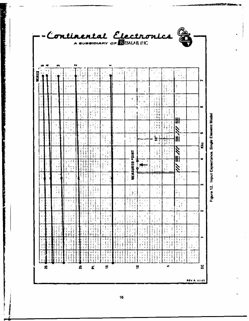
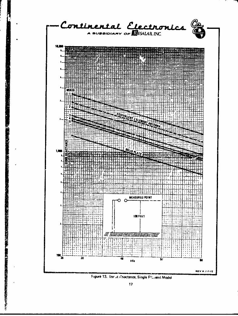
For this work, an aluminum ground plane system at a mode&scale of 1:120 was constructed and data was taken on variouswire configurations. The best configuration for each number ofwires is shown in Figures 6 through 11. The capacity for eachwas meauured at dc and was also computed from the reactancemeasurements over th, equivalent scale frequency from 3.25 to7.2 MHz. A summary if the capacitance data is shown in Figure12, and the reactance data in Figure 13.
The optimum number of wires for the flat top appeared tobe three, four, or five, depending upon further analysis ofcorona and ground loss problems. The particular configurationfor the elements was chosen to form as long a current path fromthe element tower to the common connection at the center of thearray,. This is to take advantage of the series inductance ofthe current '--. and thereby reduce the total reactance.
t8I;

A SURSIVIAMVY ofES ALAA irC
x /% /
C2 C4
\ /
\ cI%/
/
/
/ C3
/%
/ /
Top Viw -C C •i4 am for dwulopingtop hot capacitance in 4 Wf,3fnt modal
L ~X15-46
Figure 5. Top Loading Division Between Elements
9WI _

A *SUAROMAIqY OF JUWE LAA IN(W
4
PtOC- 19.33.24 MHz 19.17.2 M:z a 19.9
SELECTED BEST CONFIGURATION2 WIRES
V
_____________________________________________RIrVA 4114
"Figure 7. Two Wire Top Loading
10

A uNSI•IOIAMV r ... ESALA, INC
OC 14 pf3.24 MHz - 14.17.2 MHz - 14.35
ONE WIRE
V
mIgV A JI14
Figure 6. Single Wire Top Loading
11

2*
A *LM ,lfIobAqv oP NESIA.,B, I.
4
PfDC- 22.03.24 MHz - 22.37.2 MHz - 22.8
SELECTED IES) CONFIGURATIONI WIRES
Figure 8. Three Wire Top Locdia
12

A *UNW*IIAPMV cp NESALAB, INC
4
pfDC- 23A314 MHz- 2427.2 MHz - 24.3
SELECTED BEST CONFIGURATION4 WIRES
V
REV A J1.13
Figure 9. Four Wiro Top Loading
13

A *UOIDAMV P UESLAB, INC"* I
4
A
PfDC 2 25.03.24 MHz- 25.27.2 MHz 25.4
SELECTED BEST CONFIGURATION5 WIRES
V
R[VA J11.14
Figure 10. Five Wire Top Loading
14

A *UOI.IAM.V OF_..WESALAML, RW
4
/
SOLID PLATE
Pf xcOC - 33 -3.24 MHz2 34.6 14207.2 MHz 36.1 630
V
REVA JIIa
¢sgure 11I. Solid P~late Top Loading
15
A SU*IOAPIVOPIESALA I IP!)C
m~~ i~N
-
411
tt'-V4
It IF
- 4144;. 7 ~r~Itit til1 11;!
Ii 4 J___
-ILV A~--
-------
I 7-1
1~- 4-4- 1 :f
H~
14-7

SECTION IV
CORONA PREIENTION
The expected voltage potential on the top load portion ofthis antenna is directly related to the radiated power by ele-mentary expressions. The design goal for radiated power is 250watts. For a short monopole, this is a field intensity of
P _ c250 (7)
Where F is the known field intensity of a short monopolawith 1000 watts of radiated power and is 186.3 MV/m at one miledistance. Therefore,
r2-50186.3 V (81
c 93.15 MV/m U)
The field intensity at o'ae mile is related to the verticalcurrent flow in any nondirectional antenna by
£ = 0.65A (10)
where A is the area in ampere degrees under the function(Reference 2)
I = f(h) (11)
where f(h) is the vertical distribution of the total current flow-ing or. the antenna. For this array, the current distribution isconstant from its base to its top hat over an electrical lengthof 0.990 (100 feet at 27 kHz) so h = 0.990 and because it isconstant
A- h x I (12)
From 10
6= 0.65 (h x 1) (13)
18
£ 93.1557- ( 14).65h .65 x .99
145 amperes (15)
In a four-element antenna, this current is divided evenly betweenthe four elements and each element has a current
IC = 145/4 = 36.2 amperes (16)
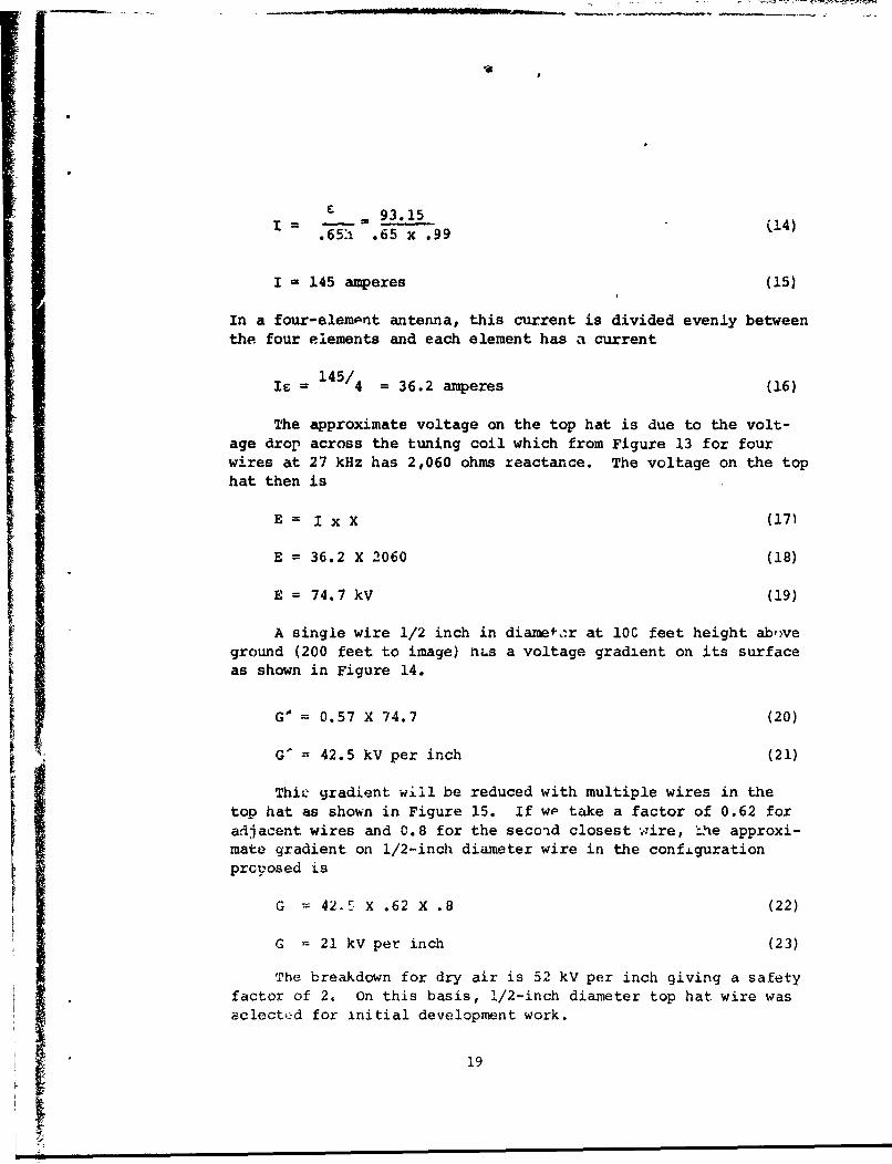
The approximate voltage on the top hat is due to the volt-age drop across the tuning coil which from Figure 13 for fourwires at 27 kHz has 2,060 ohms reactance. The voltage on the tophat then is
E= I x X (17)
E = 36.2 X 2060 (18)
E = 74.7 kV (19)
A single wire 1/2 inch in diamef,*r at 10C feet height aboveground (200 feet to image) has a voltage gradient on its surfaceas shown in Figure 14.
G' = 0.57 X 74.7 (20)
G' = 42.5 kV per inch (21)
Thic gradient will be reduced with multiple wires in thetop hat as shown in Figure 15. If wp take a factor of 0.62 foradjacent wires and 0.8 for the secoid closest wire, -hhe approxi-mate gradient on 1/2-inch diameter wire in the configurationproposed is
G w 42-5 X .62 X .8 (22)
G - 21 kV per inch (23)
The breakdown for dry air is 52 kV per inch giving a safety
factor of 2. On this basis, 1/2-inch diameter top hat wire wasselected for initial development work.
19

UrXA.X.ALA WL1JW01CPL^PWV.:ppjjESALAA INC
CORONAAIR - W WIWI"
a KvlKvANCH GRADIENT
Hit
:! I -
Upiftrm chorp on cowm0wWfIce .4,
Vdim _1>
1.3 i A
t, SPACING 3, INCH ESý,; It: t
IL
if i., LWit
fit
4 . ....................
1,; 1 1
t,-. 1-4it! tý:itt I I
iAi: lail L.3h, ý,Ll
4 1 if pp I;-
rV. _x 21r'
SQ2t7
117
4
700'
'10K 31.5 2 21!1 3 4 5 6 1 8 91.0., f.5 7 t.5 3 4 s 6 0 910"
CONDUCTOR DIAMETER d
REV 0 J4-17
Figure 14. Sui isce Voltap Gradient on VJres
20

If IA IT IAF
It 41
T- T C
T 0)
T -LL
721
SECTIOLI V
GROUND SYSTEM
A nore rigorous analysis has been made of the ground systemrequiraments to determine the minimum system which will met theefficiencl requirements. This minimum system will ease theiistallatioa requirementz and is the starting point for largescale model studies. Ijases in the immediate vicinity of the
antenna can be defined as th, ýum of "I field and H field losses.These are best specified i terms of total watts per ampere ofcurreat at the tower connection to the ground system. This valueth..-i. is in ohms and can I-e telated directly to the radiationresistance at these same terminals for computdtion of the systemefficiency and bandwidth.
The H field loss is due entirely -Lcý the radial current flow-ing in the ground from the base of the antenna caused by the cur-rent flnw on the vertical portion of th-- antenna. The E fieldloss is due to that current which flows transverse.Ly or normal toLhe radial ground wires and is equal to the antenna displacement
cu::rei.,; immediately above the surface of the ground.
The total H field current flow is divided between the radialgr,.)und wires and the earth in proportion tv their admittances.The characteristic admittance of soil is a complex number (Refer-eace
Y j) i r-IT(f, I -1 (24)S Wi-
C dielectric constant
a conductivity
lot f frequency
p permeability
The values of Y. for practical soil co.Aýiuctivities has been
calculated and is snown in Figure,16. Abbott nas also shown thatthe admittance of a parallel gr-,d ir,
22

C /LO-Pt -L4C A-MbSA LA I?, INC.
f I i f I I if P if I t -1 1 f i i if i w l i Ifif4if jjjf- Ff i ji-i j I - -4 - ++4 41HOH04 4 -1 if" I M -1--f f t f 4 111... ... I If+ Iflitl -1+11 - 44-4-14 4 1;lfii; 4 - tif l
Hil f 1 -4-14 1 t t -f-f++-H I lH114 4141 11 I-H4 -- 4-+jij i MW +--+ ifi 1141- - --H i ittitt"I", I f I I I I It 1+--111 -++4+1 MW i
i +1 IT-M 111111111-t 4-- 41, 1 ýW -41 11 HH- -P -- :'Ett III it IM 4- ---1 11 M Z,L: 117
]MIR
.............
M- MIM tit IN I- t 4
CHARACTERISTIC ADMITTANCE OF SOIL ...44414-H Milli; I L-Li+i- if I
A Y,,K(I-0-11 dt i -+H4I IRELý- i - iHl toý +f1lif H f0i -04 1' f - -1--- ++-++1 # i ifif Hitt H t4fiHil f144- -4+44--I-I-14H -14 11 -+-+Hf- H -4+444-1
-ý4 11,ý ýOtIl+;- IH44ifi, 4-14-11 1 4-4Fi--4414ii +14 11,4-41 11+44t fiil"-4 P F f-i- 1 1 -H ii + if 144+ ftii Hh4 ý01f+ -[Wilif .-+J it - --f- --H + I jii+HfjIjflf- - ++ i+fl -H+ - Hii
r T q + H- V 4+41 W I ý141+ WIT
1ý Ri 111;1 14,4t tit -J: - 1: W HIM4
T -4 1 - 111 lit - Emit =-7
K 77 j411M.1 IF Iffi ,--ft
iQ 10,rMf 3 T* - t -ý - t - I tJ-1
I ff
I I f 4- 4 I+t+ + +f
+ + 41iitl I ;t-+ f FF4++ ! 14P 11 TTT I'll
;-14 t t
_,
fl f.4 ..........
T 4
T
Z AW
tic '17 M Mq Ut01 LLi
3 4 5 6 1 1110 2 3 4 6 G I a 9 io 2 3 4 5 6 7 4 9 111
10 100 1,000
Kh3
REV A J 13-9
Figure 16. Characteristic Admittance of Soil
23

G fid loge d (25)
27ra
f frequency
p permeability
d wire spacing
a wire radius
This can be used for a radial ground system since losses aresummed from raeter square segments for which the wires may be con-sidered parallel. Values for this admittance are shown in Figure
17. Normally the total current flows in the sum of these twoadmittances and the loss is computed fer that portion which flowsin the real part of YS"
However, to find where the critical areas are for designingthe ground system, we will calculate the loss with no physicalground wires but considering a lossless theoretical connctionto the earth to skin depth.
Loss per unit area = 12/Real part of YS
The radial H field current distribution from the base ofthe element (Reference 2) for a constant current of one amperein the antenna is
h +(26)
h antenna height
D distance
I amperes per meter
This is termed the near H field in Figure 18. The expres-sion is not valid for the far field, which at a distance of 1/21meters, must satisfy the expression
24

At3LJBEJIOIALS^Fv OirIESALAB, INC.
4. 101 11 1000 i -+-+--
WIRE SPACING -4 MEER
II4 ~ ~ ~ ~ ~ ~ ~ ~ ~ E Aý JIIJ W4 iIW1 +14-~
Fiur 17 Aditac of Wir Scee No. Wireif 125 i It

K~~e~a~IDI p~vc)-,2 IJEALAg INC.
U33 v U
,t~i ~IL
li 2r
F. k
111 j d it 1 :1
PIP.
-- t- T
itC
2c0
S I tT atIN !,
91W C)
LL
Ruwa~w
Tc
RIEVA Jl12-7
26

if 1R a (27)X /4
Ra radiation resistance of subject antenna
R/4 radiation resistance of a quarterwave antenna
A quarterwave antenna has a close and far lossless currentdistribution which is inversely proportional to distance andwill equal one ampere per meter at a distance of 1/2 w meters.
S.0426 .0344 amperes per meter. (28)If = 36 ="
The inverse field and this far field are also shown inFigure 18. The ground system need not extend beyond the dis-tance where the near field intersects the far fi6ld, since thefar field current results from radiation alone.
We must examine the losses to a distance of 600 meters forthis antenna. From Figure 16, the characteristic admittance ofsoil at 27 kHz is
1= 1, YS = .046 -j.046 (29)
o = YS = .08 -j.08 (30)
O 10, YS = .15 -j.15 (31)
The ground area is segmented into annular rings, the firstbeing 10 meters in radius and the balance in 20 meter increments.The power loss per segment then is
2IS X A
PS = S (32)Y S(real)
IS average current per segment (Figure 3)
A area per segment
27

The values of loss in the ground per ampere in the antennais cumulated from the base outward as shown in Figure 19.
The E field loss is also shown in Figure 19 ind is calcul-ated by finding the depth of a solid conducting plane that isequivalent to the ground system and then finding the I2R lossdue to current flowing in the capacitor from the surface of theground to this solid conducting plane. The resistance of thesoil is
hORS = 2 h (33)
a + (WE:S 2
h equivalent screen depth
7 conductivity
2irf
Cs earth permittivi t';
for all practical soils 0'>wc , therefore
R -iL (34)s 0
the power loss is
I 2hP = S (•se
since the current in the soil equals the displacement currentdirectly above the surface
is = Id = wEE (36)
W 2iTf
c air permittivity
E electric field strength
28

J <wPIghFSALARI?,NC.
fi 1+jfl 1- 4 - - ii 1I~
f-t r -' I
4-4J
P c r4> e fr
o
CD- + o + + - -- 4 1 + -a
H I. ,.N ,H N i 4t13W IN ' ~ '14V "AitfiHl3
SWHO N~iSIi SSt
1,11 ~ ~ ~ ~ ~ ~ ~ ~ RV IN I 4-4TttT- Ti , 4 Mt
t 0 29

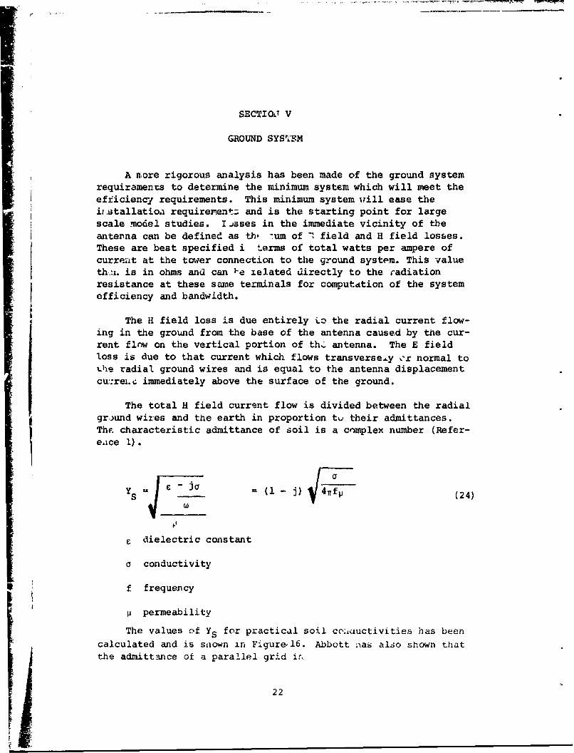
The power tf,,s then is
E2 (We) 2h (37)
se2
For clarity, let X = , which is calculated and plotteda
in Figure 20 as the specific E field loss. Then
P E2hjL (38)
The E field ratio to the H field as given by Tove Larsen(Reference 2) is shown in Figure 21 is constant current toploaded antennas. This curve has also been placed on Figure 18 toshow reference distance. To examine the lossea without a groundsystem, h is taken at skin depth in the earth or 98 meters forthe lowest conductivity. The E field loss is cumulatively shownin Figure 19.
Examinatior of Figure 19 shows that there is no more than atwo ohm contribution to the H field losses beyond 10 metersfrom the entenna Zor the worst soil. The total E fie~d loss isone ohm and lies in the area between one-half and one-towerheight, 15 - 30 meters.
It appears that a minimum ground system under the to[ loadwires and within 10 meters of the element bases will result inno more than 3 ohms ground loss per element for tne system. Wehad estimated a ground loss of 3.33 ohms in our proposal toachieve the performance requirements.
To evaluate the calculations, a minimum ground system fcr
the model was installed as shown in Figure 22. Analysis wasmade to convert the findings from the model freauency to theoperating frequency range for the full scale antenna.
30
~ ~u~e,~F~- ' !4j1SALA A INC
10,000i i.I IN1
I I UýX 1V1A1JX A
Fiur k0 xpcii E Ielt Lsw3

s'. s se~o,~nv opTIISA LA AL INC.
rcfjTTFv
dd
Rit /lEW/
figue2.Rtooflt, iis Cntn urn
jT32

A *USIDIAu m O VESALA•• .C
"-- 33'--
SDIMENSIONS SHOWN TYPICALALL FOUR SIDES
AEV S J13-12
Figure 22. Model Ground System for Test
33

SECTION VI
MODEL DESIGN
The evaluation model for this program was contractuallyrequired to be at a scale not exceeding 10:1. A smaller scaleratio will result in more accurate work and we proposed to usea scale ratio of 6.66. This ratio was chosen due to the limi-tation of our available field intensity set which has a lowerfrequency limit of 150 kHz.
The model constructed was 63.7 feet on a side and 15 feethiqh as shown in Figure 23. The scale model has the equivalentof 1/2 diameter conductors in the top hat and a solid conductorin the towers which simulates a three-wire cage to forestallcorona. This is equivalent to a two-inch sinqle conductor in thefinal antenna. It may be feasible to install a two-inch aluminumtube to eliminate the three-wire cage. This will need furtherstudy.
34

A
H- ~3.85"A
NON METALIC CORD
MNULATOR
FIETOP V•IEW 1ETON
\ f - 130 - 333 k•-z
L ___

A *UGIOAMV F IESALAB, INC
NO. 1 GUAGE WIRE -2•19E &
INSULATORS-- 15'
63.7 '
I L 14 mih
TOP VIeW
f 18U - 333 kHz
I It 4 TOWERS
ELEV!ATION
MtVi JI1-l1
Figure 23. RADC Modei Parm 35

SECTION VII
MODEL PERFORMANCE
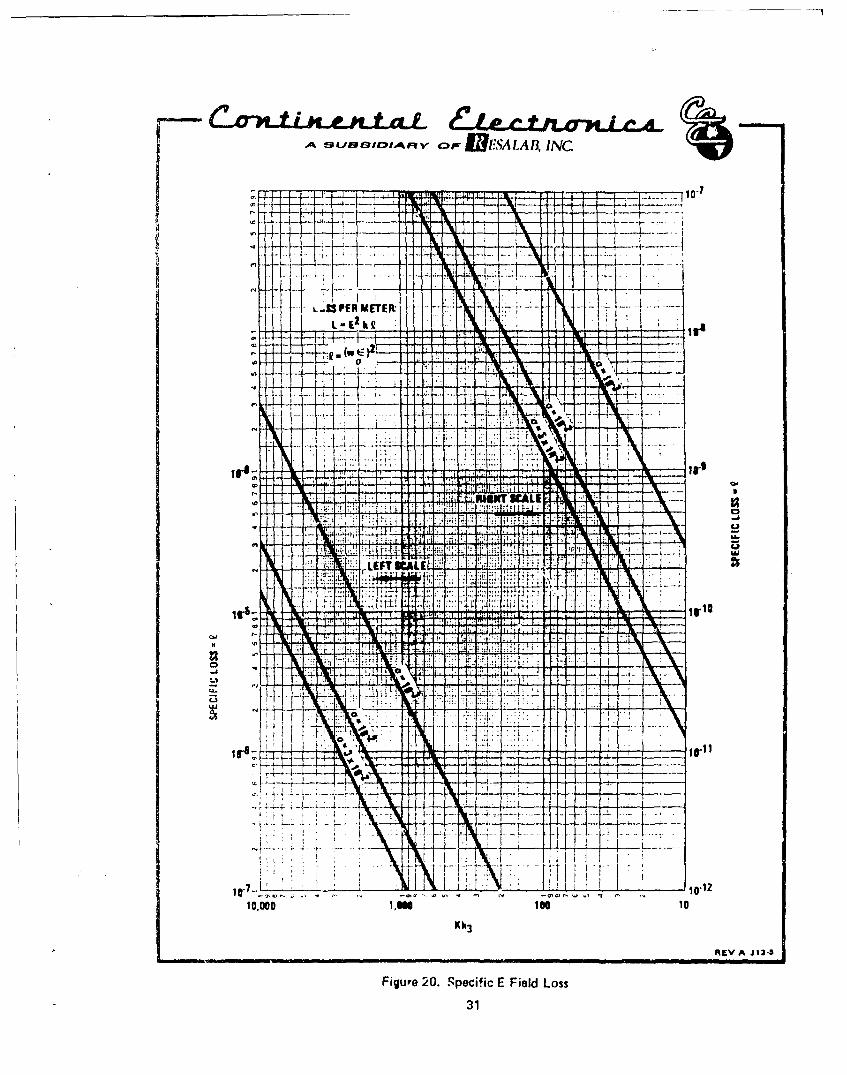
The scale model was installed and driven with 100 watts ofpower. Field intensity measurements indicated an efficiency of0.198% additional ground radials were added as shown in Figure24, which improved the efficiency to 0.226%. Field intensitymeasurements are shown in Figure 25. An analysis of the systemloss shows the following distribution.
Power radiated 0.226 wattsColl Losses 72.000 wattsGround System Losses 27.774 watts
Power Input 100.000 watts
The effective height for the model measured 14.32 feet. Themeasured bandwidth efficiency product was 2.08 Hz. At the designgoal efficiency of 0.5%, the antenna bandwidth is
-w208 (39)Bw .005
Bw - 416 Hz (40)
with matched transmitter loading, the system bandwidth will be832 Hz.
The ground losses will reduce approximately as the squareroot of the model scale
L 27.774 _T 1 (41)G V6.666
LG = 10.5 watts or 10.5% (42)
This is close to the performance predicted for 27 kHz. How-ever, the coil losses are much higher than was predicted andcould not be accounted for by usual coil design methods. It was,therefore, decided to zrake a study of coil losses and developreliable prediction methods so that the full scale antenna designand performance can be assured.
36
A *UBmIDIAMV oP IUES LAD, INC
ALL RADIALS 16' LONG• ....... •..... 4WGROUND ROD AT._..
RREVA J14-26
Figure 24. Modified Ground System
37
L A

A OU11103IDIARY opp O ESALAB, IN1C
10 ...5 ...: ..~ .. ...
. .- .~t .'; SY TE .~ .' . f . ~ +H .- .
it, -:+- = ~ hi-t-I-.
UzI
14tIt+4I 111 I
wTt
Figur1. 25 Fhel I'e t Me4re!t
L M.

SECTION VIII
INDUCTOR LOSSES
Numerous works on inductors and their losses are to befound in literature. The most extensive work on inductorloss is that of Butterworth (Ref. 5) who considered a coil asshort cylindrical parallel sections of conductor, and determinedlosses as the result of the magnetic fields produced. For singlelayer solenoids, the ac resistance, as related to the dc resis-tance, is given by
22c +_~ 2(3H ) Gdc cI
H is the skin effect of each conductor and the next termis the mutual coupling or proximity effect between the turns.The tables of Butterworth are published by Terman (Ref. 6)wherein the values of H are related to his function
x = ird V 2f/p (44)
for copper
X = 0.1078d V f (45)
d = wire diameter, Cm
f = frequency, Hz
Values of X are shown in Figure 26 for the frequency rangeof interest. The vdlueq of H in this range of conductors andfrequency are shown in Figure 27 as taken from the referencedtables, G from those taoles is shown in Figure 28. The parame-
ter u from the tables is plotted in Figure 29. The quantity do/cis simply the wire diameter divided by the spacing between turnsand has been plotted for convenience in Figuce 30.
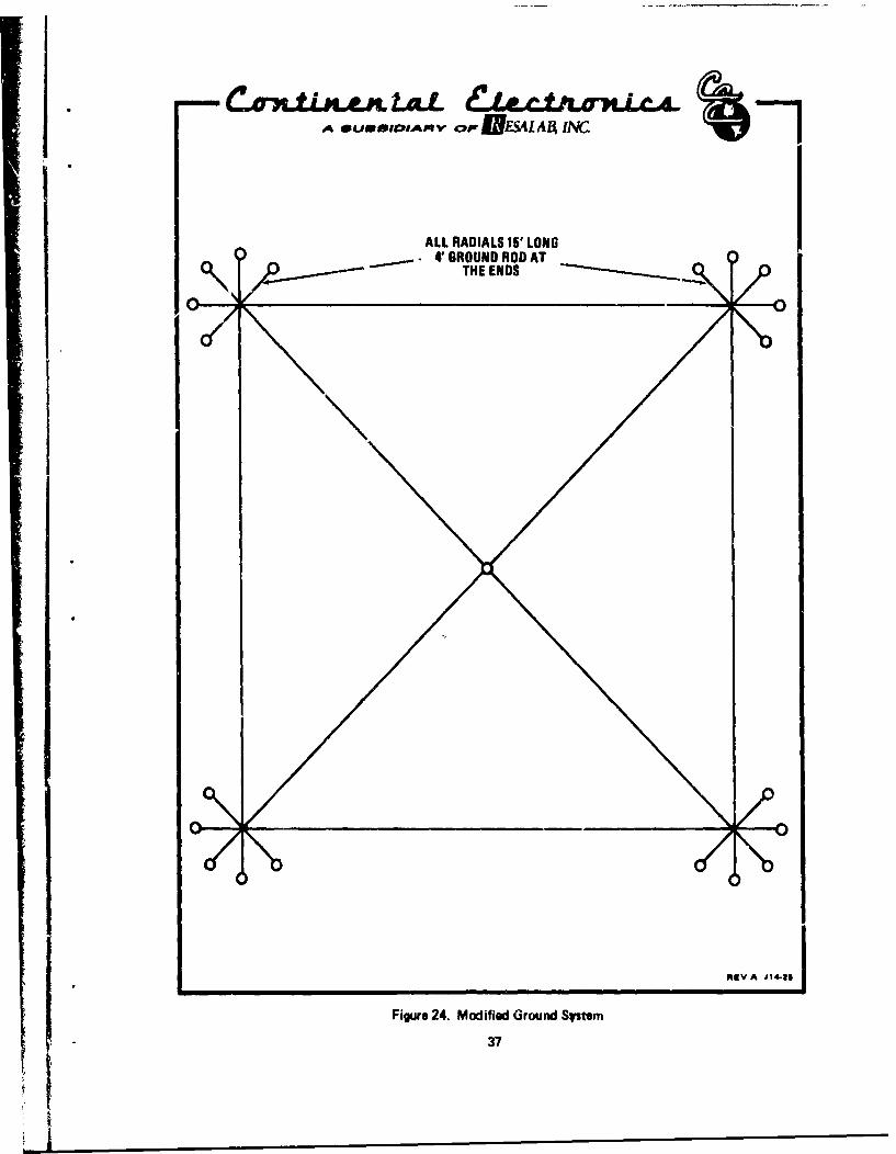
The first fabricated test Coil A is shown in Figure 31. Thiscoil was designed to nave the inductance required )r the scalemodel PARAN antenna now undergoing study. F. gure 32 shows themeasured impedance of Coil A and Figure 33 shows the measured Q.
39

IJI-A I-A It, INC
~! I
til I .li
IF ' I :0ME I ML It
Im it rn tNu 11111113 f
I ~ ~ ~ k A11flfl SHIN fil6
40RV lfi

ýMESALAA INC
T-14 q
jf4i r
7 W, Q
ME
tj4- T I 1 -1 fý 4 4 17L*
t 1 .1.j#- t ýR
00Wi
I t:
t 4
IT
HS-4,1 4,f
Tý 4fill
:+ 101-.I
F,to if
44,It: oiltt't,
0,0
1- .00
tMfw 11!T -:- T-1 I
FT
4f i ý14
ID2, T jar -. 094'
4.
14 j
OQf-11
t Z42.3, fif !,it4 0101F 010
-;Oo
io
04-OL
3 4 91.0
IMRE DIAMETER-CM
Figure 27. H-Function Skin Effect RRV A J19-23
41

~~ ,ANEMLAIA MA
-
7-7
+ -- i:-'i-
E3113JIA 110-24
j ~~~42 *V 14

TýT _Vil -L
- - A
~-443~47;. 14
tt.-t
Z0
H43
7,E A JT-2
LI ___

.i: : * . . ... ...A.
Fiu P3., SpcnT ucinPoiiyEfc

A USImu ,ApRV o EUBSLA BES N 1C
32"
30...
64 TURNS1/4 INCH 0D (COPPER TUBE
.035 INCH WALL THICKNESS
.025 SQUARE INCHES COPPER CROSS SCCTION AREA500 FEET LENGT" OF CONDUCTORDC RESISTANCE 0.32 OHMS PER 1,000 FEET1/2 INCH SPACING BETWEEN TURNS410 kHz SELF RESONANT FREQUENCY
NEVA1J20 jFigure 31. Test Coil A
45
. .... ..
..... ....
44
15SANE . ..
!it .l
FREGTENCtl....~~~LL~~iiti __________ ** * 1
4 2 253AE IVJ
100Figre32.Coi AIr dane 6 100

C~oLLJALD,.LAL do1tC0.vw17LcA. AmwcvL~lP.vo c-c
-... .FSALA 1A INC
2 3 5~ 6 7 .I
04
.j
t I T i ý 1.- 1 1.::6
471
4i

Figure 34 shows the measured loss performance of Coil Acompared w.th the calculated values. The measured loss resis-tances were normalized to ohms-per-thousand-feet of conductorfor easy comparison of inductors and published wire data. Thecopper tubing cross sectional area is equal to a round wire of0.18 centimeters in diameter.
It can be seen that below 100 kHz, the ur..asured values equalthe predicted values of loss resistance. Above this frequency,the measured values diverge upward quite rapidly. Further meas-urements show that this coil is going into parallel resonancewith its distributed capacity and that this resonant frequencyis 480 kHz. The peak in the Q of this coil from Figure 28 is
at a frequency of 120 kHz and the roll-off of the Q above thisfrequency is due to approaching resonance.
"Terman (Ref. 7) has shown th&t the increase in resistance asresonance is approached is
R total 1R actual (i _2 )2 (46)
Where y is the ratio of the working frequency to resunancefrequency. This term has been calculated and is shown inFigure 35. By applying this ratio from Figure 35 to the knownac series resistance of the coil above 100 kHz from Figure 34,ai analysis of the measured coil performance as compared withthe calculated performance is shown in Figure 36.
Tii r xpression for inductors wound with multi-strand insu-lated Litz wire (Ref. 8) is
ac Resistance =2 (47)dc Resistance H + + Vo) ds G
n = number of strandsds = dia)ueter of individual strands
48

* *5.,OV p ESALAB. INC.
404
ILAIH1111,LK
IN

Ap 4 4C tAAVLL&& MA^AA-A4=7L*WV0
-RES41AR INC
MMMIN fammma lot dfff-H, +9 4 1,014, -------
f M114 H
AT APTIi4 ,
ItO R 1
727 RJ. CMuff k HAMWI I M!i 2)i"T
(1 -7 ý t,' - f110111 J!11 OUT 1; lit I;'14 $MV t IfME, 4`1CII
3- RUN
11 imi; lit.1 Ulu -1, itt
t
114
T
cc I t', t1ifit 1''i4 1 4 1
;I 1ý Viýllj' 0 1I I !t: 4 1 14'
_f + "Kt
,14H 1,LU
141
L3W LU Uj9-
4 4; + '11016 1! Alý if;
'lag + pv - M
f 1 1, 1' i : 1.1 4 . 1 1 7,$1,14411 1w41 ;. + I I *,ý_- Sum i A lipi rT ý I i Iý il-fý ;If
T;;J iftý!! VTH 1H ý tllltý,! 4
iji! 1 4 1 11
+4
UJIioI J I a U,
TT.; fý*i 1 '!1
2
!M -H 4:7-
--Y+
j,.1E I
4Ti-4
+4
1 4
4T+It 11 1 1 L t
.01 115 2 2.5 3 4 1 6 11 a 9 2 2.5 3 4 5 6 H 9
WORKING FREQUENCY yCOIL RESONANT FREOUENCY
REV A i it is
Figure 35. Effect of Parallel Resonance in Coils
50

...... . -1WESALAB, INC.
100 ........ .......
fill I A-11 CALCULATEDL fill
RESONANCE5 EFFECT
I
3
2I I TT
t iMEASU ED ALUESUJI 11 . .-.11 _7 7, TMI JulU . I.. I I I I I I
7 111 lif- F" H+W tillfill
CC =;: . . . .. - . ;-.; -444LU -t-
I T
a ?, -it T
LAA ýV, I V J.Q
CALCULATEDT2 4 PnOxImn,"' EFFELTS w
ý,4 I FCALCULATED-4-
M_ A KIN EFFECT
0 tto 4 Av 7- Opp i i:ý., i f Jýi 4-ijtj-+jjj+j--t-- Iý
4 4 OF. if i --fffi iH f _++_fHf-lfl__-H+ f-IH4 fHi Hf: -,, f-11 +Hj fj++- A ý -t-H-- J-41+ HHHH11-t- f! ilf,
r tTI 111 1-r
44 flý -44 ý!TlfY R -11
tit -1 44444
4+F+
OC RESIST NCE 4t f,'IT RepOduced Py.
t Lf Týý 4 1 ý Co.
t j!
HIT
2 3 4 6 6 7 8 913 2 3 4 5 6 1 3 9100 2 3 4 5 6 7 a
FREQUENCY kHzRV A J19- 25
Figure 36. Coil A Analysis
5!
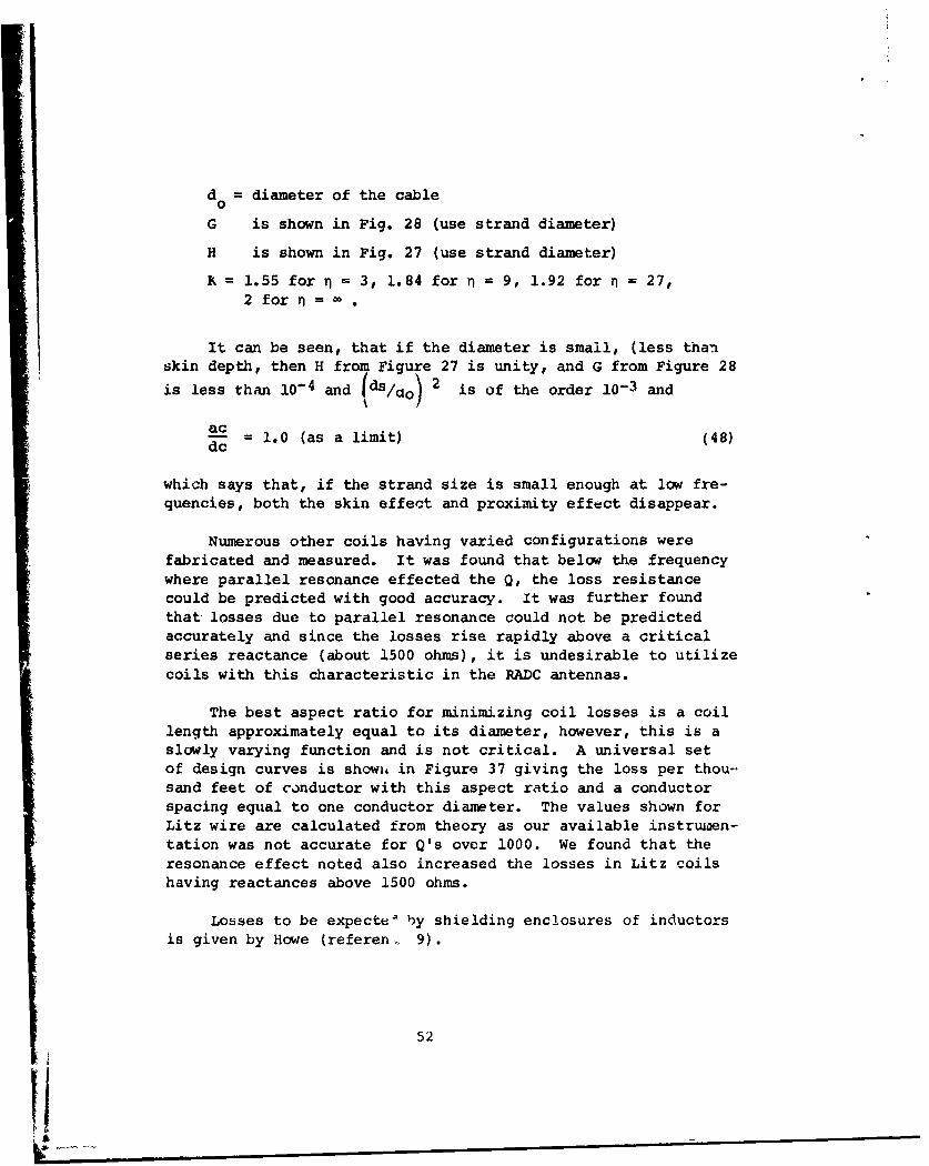
d = diameter of the cable0
G is shown in Fig. 28 (use strand diameter)
H is shown in Fig. 27 (use strand diameter)
X 1.55 for n = 3, 1.84 for r = 9, 1.92 for n = 27,2 for .=
It can be seen, that if the diameter is small, (less thanskin depth, then H from Figure 27 is unity, and G from Figure 28
is less than 10-4 and (ds/aO 2 is of the order 10-3 andac
2 = 1.0 (as a limit) (48)
which says that, if the strand size is small enough at low fre-quencies, both the skin effect and proximity effect disappear.
Numerous other coils having varied configurations werefabricated and measured. It was found that below the frequencywhere parallel resonance effected the Q, the loss resistancecould be predicted with good accuracy. It was further foundthat losses due to parallel resonance could not be predictedaccurately and since the losses rise rapidly above a criticalseries reactance (about 1500 ohms), it is undesirable to utilizecoils with this characteristic in the RADC antennas.
The best aspect ratio for minimizing coil losses is a coillength approximately equal to its diameter, however, this is aslowly varying function and is not critical. A universal setof design curves is showiL in Figure 37 giving the loss per thou-sand feet of conductor with this aspect ratio and a conductorspacing equal to one conductor diameter. The values shown forLitz wire are calculated from theory as our available instruiaen-tation was not accurate for Q's over 1000. We found that theresonance effect noted also increased the losses in Litz coilshaving reactances above 1500 ohms.
Losses to be expecte' by shielding enclosures of inductorsis given by Howe (referen. 9).
52
Ii

- SES...A INC
14
U.U
41~~~ ~ ~ Iif!.1 CAl-.
Ul 4
E-
C21
12~ A4 K1-53 wl
liO~rIOFO3 ~ ±ii mi~3d &LH

R 9.37 x 10- 4 N2 v4 f- (49)S C
v4
N number of turns
vc = radius of coil
v = radius of spherical shield
f = frequency in Hertz
p = resistivity of shield = :.727 x 10-6 for copper
R = coil series resistance
For rectangular shields, the mean dimensions approximatingan equivalent sphere may be used. The solution for this equa-tion is shown in Figure 38 at 100 kHz, and can be applied toother frequencies as shown thereon.
54

C A 0S0100^m C.UESALAB. INC
IW
~ I I
4 44i fi' +J+ Lt .
Al ;P;i~ 1!.41PT i. J.dO IU fI! M-11 U14 T' i I!
::rSI-,twv~ A 1 t.1
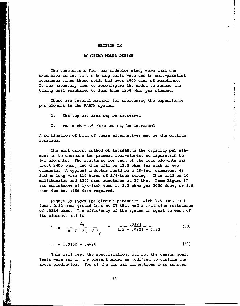
SECTION IX
MODIFIED MODEL DESIGN
The conclusions from our inductor study were that theexcessive losses in the tuning coils were due to self-parallelresonance since these coils had over 2000 ohms of reactance.It was necessary then to reconfigure the model to reduce thetuning coil reactance to less than 1500 ohms per element.
There are several methods for increasing the capacitance
per element in the PARAN system.
1. The top hat area may be increased
2. The number of elements may be decreased
A combination of both of these alternatives may be the optimumapproach.
The most direct method of increasing the capacity per ele-ment is to decrease the present four-element configuration totwo elements. The reactance for each of the four elements wasabout 2400 ohms. and this will be 1200 ohms for each of twoelements. A typical inductor would be a 48-inch diameter, 48inches long with 110 turns of 1/4-inch tubing. This will be 10millihenries and 1200 ohms reactance at 27 kHz. From Figure 37the resistance of 1/4-inch tube is 1.2 ohms per 1000 feet, or 1.5ohms for the 1250 feet required.
Figure 39 shows the circuit parameters with l.5 ohms coilloss, 3.33 ohms ground loss at 27 kHz, and a radiation resistanceof .0224 ohms. The efficiency of the system is equal to each ofits elements and is
-r R06 - .0224 (50)
RL T Ra T R 1.5 + .0224 + 3.33
.00462 = .462% (51)
This will meet the specification, but not the design goal.Tests were run on the present model as modified to confirm theabove prediction. Two of the top hat connections were removea
56

~ *U *IDA~f F IESALAAJ 1W-2
LL- 1200• 1
RL RL - 1.5
Re Re - 2 X .0112 =.0224 0
I/Il--I////-R.j R, 3.33 z
(ASSUMING CONSTANT CURRENT THROUGHOUT THE ARRAY)
REV A X14-26
-ilure 39. Circuit Two Element PARAN Antennm57

and the following measurements were made using the presentlyinstalled coils which were tapped down to produce resonance.
100 Watts Input
Measured Coil Reactance 1480 ohms
Measured Coil Resistance 3.1 ohr.-
Measured Coil Current 2.72 amps
Measured Base Current 2.3 amps
Measured Field Intensity 2.73 mV/m
Radiated Power .215 watts
Measured Efficiency .215%
Ground Resistance 5.5 omuns
Radiation Resistance .0204 ohms
Top Hat Voltage 90 kV (50 kW)
correlating with predictions from Figure 39.
With a lower reactance top hat, the tower base currents andthe coil currents have a smaller ratio as shown by the measure-ments. The coil resistance can be transferred to the tower baseby the square of the current ratio to retain the power loss con-ditions.
-- = 3.1 x N.2) (52)
base Rcoil Ibase \ (2 \
oaseeRs = 4.85 ohms (53)
.0204 x 100% (54)4.85 + .0204 + 5.5
S= .218% (approximately .215 as measured) (55)
58

Therefore as previously shown, if the coil loss is 1.5 ohmsand the ground loss is 3.33 ohms, the efficiency will be
.0204 (56)1.5 + .0204 + 3.33
= -. 42% (57)
By adding two supports and driving three elements as shownin Figure 40, the antenna can be made to meet the design goal of.5% efficiency. This antenna has approyimately the same diameteras the diagonal of the previous four-element array i,.d reducesthe top hat reactance to 1000 ohms for each of the three tunedelements.
The predicted efficiency from Figure 41.
- .0336 x 100 % (58)
1.5 + .0336 + 3.33
= .692% (59)
A model of this antenna was installed and measurements takenas follows:
100 Watts Input
Measured Coil Reactance 970 ohms
Measured Coil Resistance 3.0 ohms
Measured Coil Current 2.075 amps
Measured Base Current 1.9 amps
Measured Field Intensity 3.5C mV/m
Radiated Power .354 watts
Measured Efficiency .354%
Radiati.on Resistance .0327 ohms
Ground Loss 5.62 ohms
Top Hat Voltage 45 kV (50 kW)59

C~~tA7WLJCLAL &LLUWA *UvoIDIAF^V OF_ WESALA,, IIINC
340K
PLAN
100'
"AL
ELEVATION
REV A X14-27
Figure 40. Three Element PARAN Antenna
60

A *UOM ,IAOY o, Ia#C
RL L L 1,000 2
RFe 3X.0112=Ra R .0336 S
R Rz3.33
P EV A X 14-2
Fiqure 41., Circuit Three Elemegt PARAN Antenna
61

Correlating with predictions from Figure 41, the equivalentcoil loss at the antenna base is
-__/I \ /2.075 2
R R c 19b )2 (2.075 (60)
R(coil at base) = 3.28 ohms (61)
rl = - .1 ,/(62)3.28 + .0327 + 5.62
n = .365 (approximately .354%) (63)
Here again, if the coil loss is 1.5 ohms and the groundloss is 3.33 ohms, the efficiency will be
.0327 X 100 (64)
1.5+ .0327 + 3.33
P = .673% (65)
As requested by RADC, field intensity measurements wereextended to 40 miles on this model as shown in Figure 42.
02II

MILES1.0 2 4 6 8 10 20
t 100 FEET HIGH:'i;hý T. t inc 27KILOCYCLES f.a~ K
-fLSAA uI
~~~ 41I
jj-.4 4
7F TANTENN DECI IONMLLM
100 FETHG
J u ill! 4*2~~..,''j:
MILE7 flEVA X14-21
DEIN63 FCENY02

SECTION X
CONCLUSIONS AND RE,.'OMMENDATIONS
With the increased characteristic admittance of soil at 27kHz, it appears that the 5.5 ohm cround resistance of the modelwill be close to the predicted 3.33 ohms using the presentground system. It appears that a reasonable coil size using 1/4-inch tubing will hold coil losses to 1.5 ohms at 27 kc. This canbe further reduced with larger tubing or Litz wire.
During the last month's tests, the original top hat config-uration was strapped together at the towers, thereby eliminatingthe angular current path for each element. There was no changein the resonant frequency of the antenna model. The reason forthis change was to simplify the mechnical design and reducestructural loading. It appears that there is little or no effec-tive series inductance in the special configuration and it can beeliminated for a more unified lacing of the top hat as shown onthe three-element model of Figure 40.
The development work has now reached the point where twomodels have been developed and tested. One will more than meetthe specified efficiency of 0.2% efficiency as obtained on themodel and wit11A proper design, the full scale model should exceed0.4% efficiency. The other scale model has achieved 0.354% effi-ciency, and with prop.: design, should exceed the design goal of0.5% efficiency for the full size model.
The final configuration should be capable of more than tht 50kilowatt input requirement and can be designed for at least 100kilowatts. It is recommended that a full scale prototype be erec-ted for the purpose of determining the upper limits on efficiencyand power handling capability.
64

REFERENCES
1. Radio Antenna Engineering by LaPortePage 25
2. Radio Antenna Engineering by LaPortePage 24
3. "Design of Optimum Ground System Procedure"IRE, July 1952 by Frank Abbott
4. "E & H Field Loss Ground SysLems"Journal of Research NBS, March 1971by Tove Larsen
5. S. Butterworth, "Effective Resistance of InductanceCoils at Radio Frequencies"Wireless Engineering, 1926
6. F. E. Terman, Radio Engineers HandbookMcGraw Hill, Page 78
7. F. E. Terman, Radio Engineers HandbookMcGraw Hill, Page 85
8. F.E. Terman, Radio Engineers HandbookMcGraw Hill, Page 80
9. GWO HOWE, "Effect of Screening on Inductance andResistance of Coils"Wireless Engineering, March 1934, Page 155
65

UNCLASSIFIEDSecurity Classiflcation
DOCUMENT CONTROL DATA. R & D(Security classificatlon of tile, body of abetract and Indoming annotafion must be entered when the overall report I. c ied)
I ORIGINATING ACTIVITY (Corporate author) |2a. REPORT IECURITY CLASSIFICATION
Continental Electronics Mfg. Co. U ASIFIEDP. 0. Box 17040 b GROUPDallas, Texas 75217T 1/A
3 SPORT TITLE
.ISP•RSIBLE TRANSMITTING ANTENA
VLF/LF INMTIGATION
4 OIECRIPTIVE NOTES (Type of report and inclusive de*..)
Final Technical Report 9 Feb 71 - 9 Dee 71I AUTTHORISI (First name, middle Inltlet, tact nam.)
Hor-er A. Ray, Jr.6 REPORT OATS 78. TOTAL NO OF PAGES 7b. NO OF REPS
March 1972 657 9"Se CONTRACT OR GRANT NO 9c. ORIGINATOR'S REPORT NQMGIRKIS
1F30602-Tl-C-0O10kTob Order No.65230000,T&sk - 06 Ob. OTHER REPORT NOISW (Any other nrubbre that may III Aslg'ndWel repo•rt)
"d Item - 014 RADc-TR-72-2810 OI!TRISUTION STATEM.ENT
Approved for public release; distribution ualimited.
11 SUPPLEMENTARY NOTES 12 SPONSORING MILITARY ACTIVITY
Rome Air Development Center (COAL)Griffiss Air Forte Base, New York 13440
S1 AObTRACT
The problem vex the development of an antenna system no more than 100 feet highfor the frequency range 27 ti 60 kHz having a radiating efficiency of 0.2% with adesign goal of 0.5%. The input power capability was to be 50 kW. A theoretical de-sign sas proposed with five support towers 100 feet high and a squaZZ area of 125feet on a side. A model was constructed at a frequency scale of 6.66 to 1.0 fortesting. The nodel achieved the 0.2% efficiency, but the major loss in the systea vasthe tuning inductors. The inductor problem was studied and ths conclusion was thatinductors having more than 1500 ohms suffered unanticipated losses from circulatingcurrents due to approaching self-resonance. This led to a reconfiguration of tbeoriginal array to one having seven support towers in a hexagon 340 feet on a side.Measurements on tne kaodel indicated 0.350% efficiency with a predicted efficiencyfor the full size eatenna of 0.673%. The modification reduced the voltage on thesystem to 45 kV for 50 kW and indicate that a design for 100 kW input power isfeasibl _.
DD 1473

UICLASSII'IES~ecurity C-lasuificatiofl________
f4 LINK A LINK U LINK CKEY w0145 -
VVLF/L, Antenna, Communicatio~ils LE T RLE W RLE
YNCIArlIFIE

A C