dislocation clustering and long-range internal stresses in
TRANSCRIPT

HAL Id: jpa-00245783https://hal.archives-ouvertes.fr/jpa-00245783
Submitted on 1 Jan 1988
HAL is a multi-disciplinary open accessarchive for the deposit and dissemination of sci-entific research documents, whether they are pub-lished or not. The documents may come fromteaching and research institutions in France orabroad, or from public or private research centers.
L’archive ouverte pluridisciplinaire HAL, estdestinée au dépôt et à la diffusion de documentsscientifiques de niveau recherche, publiés ou non,émanant des établissements d’enseignement et derecherche français ou étrangers, des laboratoirespublics ou privés.
Dislocation clustering and long-range internal stresses inmonotonically and cyclically deformed metal crystals
H. Mughrabi
To cite this version:H. Mughrabi. Dislocation clustering and long-range internal stresses in monotonically and cyclicallydeformed metal crystals. Revue de Physique Appliquée, Société française de physique / EDP, 1988,23 (4), pp.367-379. �10.1051/rphysap:01988002304036700�. �jpa-00245783�

367
Dislocation clustering and long-range internal stresses inmonotonically and cyclically deformed metal crystals
H. Mughrabi
Institut für Werkstoffwissenschaften, Lehrstuhl I, Universität Erlangen-Nürnberg,Martenstrasse 5, 8520 Erlangen, F.R.G.
(Reçu le 26 mai 1987, accepté le 14 août 1981)
RESUME. - On passe en revue les structures de dislocations en parois et cellules dans les cristaux
métalliques déformés, en insistant sur l’hétérogénéité de distribution des dislocations. L’évolu-tion de la sous-structure de dislocations est décrite en terme d’écrouissage et restauration dyna-mique. L’article insiste sur le modèle dit "composite" dans lequel la distribution hétérogène desdislocations est considérée comme un matériau composite constitué de parties dures et molles corres-
pondant aux parois et intérieurs des cellules, respectivement. Des contraintes internes à longueportée, d’amplitude cohérente avec l’expérience, font partie du modèle composite. Elles sont une
conséquence des conditions de compatibilité en cours de déformation. Le modèle composite permet unenouvelle compréhension de la contrainte macroscopique d’écoulement plastique et une bonne descrip-tion du chargement inverse, y compris l’effet Bauschinger dans le cas des monocristaux.
Abstract. - Dislocation wall and cell structures in deformed metal crystals are reviewed briefly,emphasizing the heterogeneity of the dislocation distribution. The evolution of the dislocationsubstructure is discussed in terms of work hardening and dynamic recovery. The main part of thepaper deals with the so-called composite model in which the heterogeneous dislocation distribution isconsidered as a composite consisting of bonded hard and soft components corresponding to cell wallsand cell interiors, respectively. Long-range internal stresses whose magnitude is consistent withexperiment are an integral part of the composite model. They arise as a necessary consequence of thecompatibility requirements during deformation. The composite model leads to a new understanding ofthe macroscopic flow stress and to a good description of reverse loading including the Bauschingereffect in the case of single crystals.
Revue Phys. Appl. 23 (1988) 367-379 AVRIL 1988,Classification
Physics Abstracts46.30J - 81.40L - 62.20F
1. INTRODUCTION
The dislocation microstructure of deformed metals ischaracterized by the mutual elastic interaction ofthe dislocations and by their tendency to cluster inorder to form dislocation tangles, walls and, inmost cases, three-dimensional dislocation cell lstructures, for recent reviews compare [1,2].Whereas dislocation tangles (braids, bundles) andwalls can form under single-slip conditions, theformation of three-dimensional dislocation cellstructures is typical of combined single and secon-
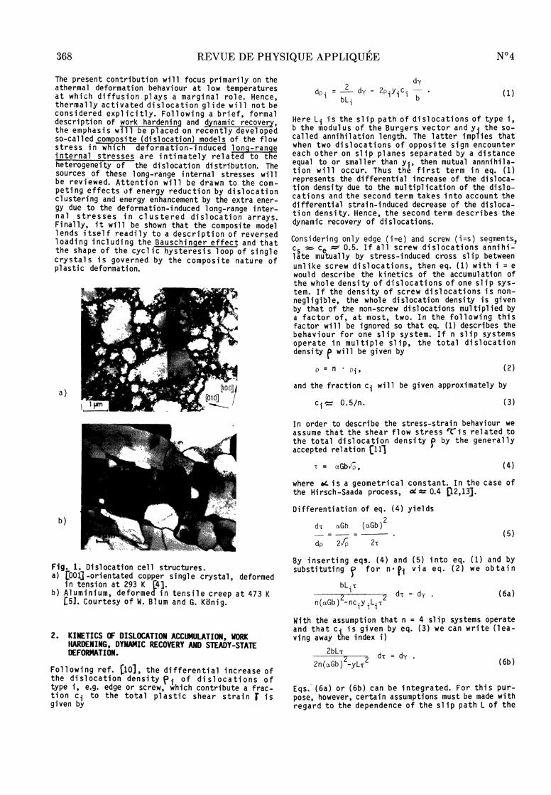
dary slip or multiple slip. The heterogeneity ofthe dislocation distribution is an important fea-ture common not only to monotonically but al so tocyclically strained metals t3].Dislocation cell structures form both at low and athigh temperatures, differing, however, in their qua-litative appearance, as illustrated in Fig. 1. Atlow temperatures the cell walls are "untidy" andhave non-negligible thicknesses (Fig. la). At highertemperatures they become much sharper and approachideal low-angle boundary configurations (Fig. lb).
REVUE DE PHYSIQUE APPLIQUÉE. - T. 23, N° 4, AVRIL 1988
The cel 1 structures encountered i n fatigue can beconsidered to be of an intermediate type in thesense that, for example, ot-iron [6,7jand copper(,81 fati gued moderately at room temperature exhibitcell structures of the low-temperature type whichapproach cell structures of the high-temperaturetype after extensive cyclic deformation. Frequently,misorientations from cell to cell are found. It
appears, though this is not documented systematical-ly in the literature, that the misorientationsacross cell l walls of the low-temperature type arerTt’Jch smaller [4,9]than in the case of the planarsubcell boundaries typical of high-temperature de-formation. Qualitatively, this can be related to thefact that while the "thicker" cell 1 walls formed atlow temperatures contain dislocations of both signsand hence have a dipolar character, the low-angle-boundary-type cell walls characteristic of hightemperatures consist predominantly of dislocationsof only one sign. At a given temperature, themisorientations increase with increasing deformationL 4 -8 J.
Article published online by EDP Sciences and available at http://dx.doi.org/10.1051/rphysap:01988002304036700
368
The present contribution will l focus primarily on theathermal deformation behaviour at low temperaturesat which diffusion plays a marginal rôle. Hence,thermal ly activated dislocation glide will l not beconsidered explicitly. Following a brief, formaldescription of work hardening and dynamic recovery,the emphasis will l be pl aced on recently devel opedsa-called composite (dislocation) models of the flowstress in which deformation-induced lonq-rangeinternal stresses are intimately related to theheterogeneity of the dislocation distribution. Thesources of these long-range internal stresses willbe reviewed. Attention wi 11 be drawn to the com-peting effects of energy réduction by dislocationclustering and energy enhancement by the extra ener-gy due to the deformation-induced 1 ong-range inter-nal 1 stresses in clustered dislocation arrays.Finally, it will be shown that the composite modellends itself readily to a description of reversedloading including the Bauschinger effect and thatthe shape of the cyclic hysteresis loop of singlecrystals is governed by the composite nature ofplastic deformation.
Fig. 1. Dislocation cell structures.a) [001]-orientated copper single crystal, deformed
in tension at 293 K [4].b) Aluminium, deforme i n tensile creep at 473 K
[5]. Courtesy of W. 81 um and G. Kdnig.
2. KINETICS OF DISLOCATION ACCUMULATION, WORKHARDENING, DYMAMIC RECOVERY AND STEADY-STATEDEFORMATION.
Following ref. (10) , the differential increase ofthe dislocation den s i ty f i of dislocations oftype i, e.g. edge or screw, which contribute a frac-tion ci to the total plastic shear strain f isgiven by
Here Li is the slip path of dislocations of type i,b the modul us of the Burgers vector and y. the so-called annihilation length. The latter impiies thatwhen two dislocations of opposite sign encountereach other on slip planes separated by a distanceequal to or smaller than yi, then mutual annnihila-tion will occur. Thus the first term in eq. (1)represents the differential increase of the disloca-tion density due to the multiplication of the dislo-cations and the second term takes into account thedifferential strain-induced decrease of the disloca-tion density. Hence, the second term describes thedynamic recovery of dislocations.
Considering only edge (i=e) and screw (i=s) segments,Cs ~ ce - 0.5. If all l screw dislocations annihi-late mutually by stress-induced cross slip betweenunl i ke screw dislocations, then eq. (1) with i = e
would describe the kinetics of the accumulation ofthe whole density of dislocations of one slip sys-tem. If the density of screw dislocations is non-negligible, the whole dislocation density is givenby that of the non-screw dislocations multiplied bya factor of, at most, two. In the following thisfactor will be ignored so that eq. (1) describes thebehaviour for one slip system. If n slip systemsoperate in multiple slip, the total dislocation
density p will be given by
and the fraction ci will be given approximately by
In order to describe the stress-strain behaviour weassume that the shear flow stress ecis related tothe total dislocation density f by the generallyaccepted relation (111
where 61- is a geometrical constant. In the case ofthe Hirsch -Saada process, ~ ~ 0.4 [12,13].Differentiation of eq. (4) yields
By inserting eqs. (4) and (5) into eq. (1) and by
substituting f for n- pi via e q. (2) w e obtain
With the assumption that n = 4 slip systems operateand that ci is given by eq. (3) we can write (lea-ving away the index i)
Eqs..’ (6a) or (6b) can be integrated. For this pur-pose, however, certain assumptions must be made withregard to the dependence of the slip path L of the

369
dislocations and of the annihilation length y onthe fl ow stress 77 (or on the shear strai n X’ ).Before proceeding further, it must also be notedthat eqs. (6a) and (6b) do not take the heterogenei-ty of the dislocation distribution into account atall. Strictly speaking, they apply only to homoge-neous (uniform) dislocaton distributions. They mightthus be applied locally in regions of relativelyuniform dislocation distribution such as, in thesimplest case, the cel 1 wall 1 or the cel l interiorregions. In this case, the slip path L would have tobe related to the latéral dimensions of these re-gions in the glide plane, namely the cell wallthickness dw or the diameter dc of the cell interiorrégions, respectively.
Bearing these restrictions in mind, we now return tothe question of i ntegrati ng eqs. (6a) and (6b).Regarding the dislocation slip path L, two cases areconsidered, namely L = const. and L = K2/rr. Thefirst case would apply, for example, to stage 1 workhardening of face-centred cubic (fcc) singlecrystals and the second case to stage II work
hardeni ng [10]. For the annihilation distance weassume y = const. or y = K1 /T. The f i rst relationhas been found to apply quite well 1(with ye ~ 1.6 nm) for pure edge dislocation arraysin copper crystals [10], the second implies a mu-
tual dislocation trapping mechanism leading to spon-taneous annihilation, for exampl e by some form ofcross sl i p [14] . The parameters K, and K2 are con-sidered to be constants at a given temperature andstrain rate. In lack of a detailed theory theyshould be evaluated from experimental data on localdislocation densities in the case of K, and, in thecase of Kz from the characteristic dimensions of thedi sl ocati on distribution and from slip line data.Very plausible results have been obtained for ar-bitrary dislocations in cell structures in deformedcopper crystals with K, = 2.14 N/m [14].
The combination of these possibilities yields fourcases (a,b,c,d) for which eq. (6a) has been inte-
grated. The resul ts are summari zed in Table 1.For L = const. a saturation of the flow stress (witha saturation stress cs and saturation dislocationdensity Ps) i s obtai ned i n cases a) (y = const.)and b) (y = K1/03C4). For L = K2/rC, saturationoccurs for y = const. in case c), whereas for
y = K1/03C4 in case d) linear hardening is obtained.
It should be noted that the annihilation distance yis expected to depend on temperature T strainrate 03B4 and stacki ng faul t energy SFE [15]. Theexact dependence should follow from a theoryyielding y = y(03B3,T,SFE). Qualitatively, it is ex-pected that decreasing z, increasing T and in-
creasing SFE will cause y to increase. The conse-quences woul d be a réduction of ’7:s and Ps incases a, b) and c) in which saturation occurs and adecrease of the linear work-hardening rate incase d).
In order to describe the deformation of a wall or a
cell structure, the coupled deformation of the wallsof high dislocation density and the dislocation-poorregions between the walls must be considered as inref. (101. In more detailed models of the evolutionof the dislocation substructure Prinz and Argon [16]and Nix, Gibeling and Hughes [173 consider dynamicrecovery to occur mainly between the walls, whereasin the walls static recovery is assumed to be domi-nant. We note here, that, in a formal manner, we can
al so descri be static recovery i n our approach by a
term similar to the second term in eq. (1), using aneffective value of the annihilation distance y thatis appropriate at a particular temperature andstrain rate.
3. THE COMPOSITE MODEL
3.1 Deformation by single slip.
The composite model represents an attempt to des-cribe in a simplistic fashion the deformation beha-viour of a crystal in which the dislocations aredistributed heterogeneously in the form of a wallor a cel l structure. In the following., an outlinewill be given of the composite model in the form inwhich it was first proposed on the basis of micro-structural TEM (transmission electron microscopy)studies on fatigued copper si n 1 e crystal s ori en-tated for single slip [,1,18,19 and later also fortensile-deformed crystals oriented for multipleslip [1,4]. A very similar model was developed byPedersen and co-workers in order to describe theBauschinger effect (201 and the cyclic deforma-tion r21] of copper single crystals of single-sliporientation. With regard to the details, some diffe-rences exist between these two related model s andalso with respect to other models [22,23] which, inthe present context, will only be noted briefly inpassing.
Fig. 2 shows the typical 1 dislocation distributionobserved by TEM in copper single crystals of single-slip orientation deformed cyclically into saturation(at room temperature). In a (l’3l) section (Fig. 2a)which contains the primary Burgers vec-
tor bp = 1 2[101] and lies perpendicular to the pri-mary glide plane (111), persistent slip bands (PSBs)with the so-called ladder or wall l structure, embed-ded in the vein or bundle structure of the ma-trix (M), are observed. The walls and the veinsconsist essentially of a very high density of elon-gated primary edge dislocation dipole loops and areseparated by "channel s" of rather low dislocationdensity [3,10,18,24-26]. Since plastic deformationi s concentrated strongly i n the PSBs which carry aplastic shear strain amplitude of almost 1% as com-pared to only about 10-4 in the case of the matrix,we shall confine our considerations to plastic flowin the wall l structure of the PSBs. The détails ofthe dislocation distribution in the wall structureare shown in Fig. 2b. Dislocation glide in the chan-nels occurs by the bowing-out of edge segments fromthe walls across the channel s and by the spreadi ngof the screw dislocations along the channels, as
illustrated schematically in Fig. 3a [18]. A neces-sary consequence of the steady-state conditionsprevai 1 i ng i n cyclic saturation is that a dynamicequilibrium must exist between the processes ofdislocation multiplication and annihilation withregard to both screw and edge dislocations [103.Aside from the gross features of the dislocationdistribution described above, the following moresubtle observation is important. In Fig. 2b whichshows the dislocation distribution pinned in thestress-applied state, it is evident that dislocationsegments near the walls are much more stronglycurved than those in the centre of the channel s. Inparticular, attention is drawn to the large numberof strongly curved short edge segments bowing out atthe periphery of the walls. The implications arethat the locally acting shear stress varies strongly

370
across the channels, increasing sharply near thewalls [1,18,19,24,26]. The results of a quantitativeévaluation of the variation of the local shearstresses from wall to wall [1,19] are shown inFig. 4 (x//dc is the distance from the "left" to the"right" wall, normalized with respect to the channelwidth dc). Considering the external saturation shearflow stress Ys e= 28 MPa as a macroscopic flowstress , it is to be noted that the local 1 shearstress Ir is si 9 ni f i cantl y lower than i n thecentre of the channels and much higher near thewalls. Mechanical equlibrium requires that the localshear stresses in the walls be approximately100 MPa [1,19j.It is concluded that significant long-range inter-nal stresses exist in the wall structure in thestress-applied state, as shown schematically inFig. 3b. The origin of such long-range internalstresses which were first noted in 1973 [27j is notimmediately clear, since the bulk of the disloca-tions are edge-dislocation di- or multipoles with nosignificant long-range internal stress fields. Itwill l be shown bel ow that the composite model ex-plains the experimental observation very satis-factorily.
The basic idea underlying the composite model isthat a crystal contai ni ng a heterogeneous disloca-tion distribution behaves mechanically like a two-phase (or multi-phase) material even if it is chemi-
cally single-phase. Referring to Fig. 2b and
ignoring details of the dislocation distribution forthe moment, the view is taken that the material is acomposite consisting of bonded dark and light compo-nents of high and low dislocation density which havecorrespondi ngly hi gh and low 1 ocal fl ow stresses,respectively. When such a composite is strained, thedéformations of the components must be compatible.The simplest assumption is that the components arestrained in paral 1 el under the condition that thetotal strain be constant throughout the structure.This assumption is based on the considération thatdeformation occurs by dislocation glide and that theglide planes are continuous through the soft and thehard components. Other si mpl i fyi ng assumptions are
that both components exhibit ideal elastic-plasticbehaviour and that they possess the same elasticconstants.The composite model, as described above, is formallysimilar to MasinQ’s model of the yielding of poly-crystals [281 . Masing considered the polycrystal as
an aggregate of bonded crystallites of varyingorientations with respect to the stress axis andwith accordingly différent yiel d stresses. He des-cribed the overall yielding behaviour under forwardand reverse strai ni ng by assuming that the grainsare strained in parallel under the condition ofconstant total (axial) strain and that they behavein an ideal elastic-plastic manner. It follows thatour composite model of a single crystal is formally
Table 1: Solutions of eq. (6a) for different combinations of slip path L and annihilation distance y.

371
equivalent to a two-component Masing model.The "hypothetical" stress-strain curves of the com-ponents 1 and 2 and of the composite are shown inFigs. 5a and 5b, respectively. For an elucidation ofthe term "hypothetical" the reader is referred toref. [1]. The macroscopic behaviour of the com-posite results from the superposition of the micros-copic behaviours of the components under due con-sideration of the area fractions f1 and f2 occupiedby components 1 and 2 in the g1ide plane, respec-tively. For all cases to be considered in thefollowing, these area fractions are identical withthe volume fractions. Yielding of the composite canbe divided conveniently into mic royielding corres-pondi ng to plastic yi el di ng o e so componentwhile the hard component is still deforming elasti-cally and into macroyielding when the material hasbecome fully plastic. An important feature of thecomposite model is that long-range internal stressesare bui 1 t-i n as an intégral part. Upon unloading,when the applied stress is reduced to zero, theselong-range internal stresses are frozen in (residualstresses) in the form of forward (tensile)stresses btr 1 and backward (compressive)stresses eT2 in the hard and in the soft components,respectively.
The two-component Masing model can be formulated forthe wall structure of the PSBs (Fig. 2) in simplerelations Il, 18, 19] in terms of the shear stres-ses ’ë: and the shear strai ns r as follows. Thesubscripts w and c refer to walls (component 1) andchannels (component 2), respectively. The compatibi-lity requirement is
Fig. 2. Dislocation arrangement in fatigued coppersi ngl e crystals [24].a) (121)-section showing matrix (M) and persistent
slip bands (PSB).b) Section parallel to primary glide plane (111) in
PSB wall structure.
where the subscripts t, el and pl refer to total,elastic and plastic, respectively. The appliedstress for a given value of 9t is given by a ruleof mixtures:
Fig. 3. Schematic illustration of dislocationbehaviour in the PSB wall l structure. After [18].a) Glide of edge and screw dislocations.b) Idealized local stress distribution in the
stress-appl ied state.c) Idealized local stress distribution in the
unloaded state.(v1, v2 : volume fractions)
Fig. 4. Variation of the local stress in the PSBchannels in the stress-applied state at a plasticshear strai n amplitude rpl:: 5 10--l [19].

372
Fig. 5. Hypothetical stress-strain curves for a two-component composite model during forward strainingand unloading. After [1,19].a) Microscopic behaviour of the components.b) Macroscopic behaviour of the composite.
(0-1 J, 0’2 and T are the current (axial) stressesof components 1 and 2 and of the composite,respectively, and 6-t’ â-2 and (rare thecorresponding (axial) f ow stresses, E is thetotal (axial) strain.)
t
At the point of macroyielding eq. (8a) reads
where -r and 7-w denote the local 1 flow stressesand thé overall macroscopic flow stress. Thelocal flow stresses Tc "and are related to the
macroscopic flow stress Z as fôllows
where 0393 is Eshelby’s elastic accommodationfactor [29] to which we shall l return later. Thestresses 039403C4c and A’Cw are deformation-induced long-range internal stresses which arise from the plasticstrain mismatch between the soft and the hard compo-nents, as expressed by eqs. (11) and (13). Theyenhance the applied stress in the hard componentsand oppose it in the soft components, ensuringoverall compatibility. Upon unloading, they are
fully retained if no reverse plastic flow occurs andonly partially otherwise, compare [1,18,191. In theunloaded state, "1: = 0, and eq. (8a) reduces to
Figs. 3b and 3c summari ze schematically the localshear stress distribution in the PSB wall structurein the stress-applied and in the unloaded states.The rectangular stress profile is, of course, an
idealization. More detailed considerations [1]lead to a more realistic profile which agreescl osely wi th that of Fig. 4.
The sources of the long-range internal stresses arethe edge dislocations of 1ike sign deposited at theinterfaces between walls and channels, as indicatedin Fig. 3a. The density of these interface disloca-tions represents only a few percent of the totaldislocation densi ty Cl3.
The most important feature of the composite model isits ability to explain the observed long-range in-ternal stresses in a straightforward manner. Inaddition, the composite model provides a betterunderstanding of the macroscopic flow stress via
eqs. (10) to (13), depending on whether the local
flow stress c of the soft or w of the hardregions is considered as a reference. In the formercase It i s equal to tc plus the back stress |039403C4c|,in the latter case it is equal to w minus tcheforward stress lA1:wl.
Returning to the Eshelby factor, it must be remarkedthat this quanti ty is not i ncl uded in a simpleMasing-type model and represents a refinement adop-ted from the continuum theory of dispersionhardening by Brown and co-workers f303and empha-sized in papers by Pedersen and co-workers (20,21)in the present context. The Eshelby factor dependson the shape of the "inclusions", i.e. of the wallsi n the present case, and on the mode of straining.It lies between zero and one. In the opinion ofPedersen et al. j2lJ, an appropri ate value for thewalls woul d bel’= 1/100. The conséquences of such a
low value woul d be a strong réduction of the long-range i nternal stresses 4:rc and 6-rw whereas, inthe present author’s opinion, the experimental re-
sults strongly indicate that"f’ must be closeto 1 j19). In fact, a val ue of 1" = 1 wi 11 be usedthroughout this paper as in earlier work [1,18,19]The choice of the value 0393 ~ 1 is deri ved from theexpérimental observations. The justification isbriefly as follows. The TEM observations of disloca-tions pinned in the stress-applied state (Fig. 2b)indicate that dislocations glide into and out of thewalls. I n si tu TEM studi es (31) support thi s pi c-ture. Hence, it can be concluded that the harddislocation walls are not only strained elasticallybut do in fact yie1d plastically (1,18,19a. Therequired relatively high local stresses are providedby the applied stress plus the aiding forward inter-nal stress 039403C4w, cf. eq. (12). According to themeasurements of the local 1 shear stresses (Fig. 4),the shear stress acting locally in the walls isabout 100 MPa which is considered of the right mag-nitude in order to cause dislocation glide in thewal 1 s. If, on the other hand, 1- were much smal l erthan one, as suggested by Pedersen et al. C 21),arc would be reduced significantly. I n this case,neither the large values of the long-range internalstresses deduced from the observations nor the
373
bowing-out of small 1 edge segments from the wallscould be explained in terms of the composite model.As will be shown later, the analysis of the shape ofthe hysteresis loop also leads to the conlusion thatthe walls yield plastically (and that 1"-- 1).
3.2 Déformation by multiple slip
Until 1 quite recently, dislocation ce11 structuresformed during multiple slip deformation weregenerally considered to be energetically favourabledislocation arrays with insignificant long-rangei nternal stresses, c.f. [2]. This contrasts thesituation in the case of single-slip deformationwhere long-range internal stresses (due to disloca-tion pile-ups) had been an important ingrédient ofstage II work-hardening theories [32,33 1Recent X-ray studies on [0011-orientated coppersingle crystals deformed in tension at room tempera-ture [4] have provided convincing evidence thatsignificant long-range internal stresses exist alsoin dislocation ce11 structures. This conclusion isbased on a detailed analysis of the experimentalobservation that deformation-induced broadening ofthe {002} X-ray ref 1 ec ti on profiles is asymmetric.For détails, the reader is referred to the originalpaper [4J. Si mi 1 ar resul ts have in the meanwhile
also been reported for copper polycrystals deformedin tension at room temperature [341.
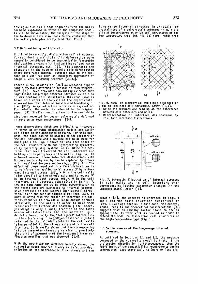
These observations which are difficult to interpretin terms of existing dislocation models are easilyexplained i n the composi te picture. For thi s pur-pose, the model has to be adapted to the geometry ofthe cell structure and allowance has to be made formultiple slip. Fig. 6 shows an idealized model ofthe cell structure with two intersecting symmetri-cally operating slip system s Cl,41. Glide disloca-tions that have traversed the ce11 interiors areheld up at the periphery of the walls (Fig. 6a). Ina formai manner, these interface dislocations withBurgers vectors b1 and fi can be replaced by otherswidth resul tant Burgers vectors b (fit. 6b). Theeffect of these résultant interface dislocations isto reinforce the applied axial stress a- by a for-ward i nternal stress 039403C3w> 0 in the cel 1 wal 1 slyi ng paral l el to the stress axi s and to reduce çrby an internal back stress 4U-, 0 in the cellinteriors, as illustrated schemaîically in Fig. 7.(At the same time the walls lying perpendicular tothe stress axis are subjected to internal compres-sive stresses in the latéral (horizontal) direc-tion.) As in the case of single slip (Sect. 3.1), itmust be noted that the number of interface disloca-tions required to provide a large enough forwardstress 039403C3w i n the wal 1 s i n order to make themtransparent to further dislocation glide (macro-yielding) is on1y a small fraction of the totalnumber of dislocations [4]. The insets in Fig. 7
depict schematically the "tetragonal" lattice dis-tortions f referring to an [001]-orientated crystal)retained in the unloaded state in the cell wallslying parallel to the stress axis and in the cellinteriors. It is easily shown that the correspondinglattice parameter changes give rise to preciselythat kind of asymmetry of the broadened X-ray re-flection profiles that was observed [1,4].
With the modifications outlined briefly above, the
composite model provides a very satisfactory des-scription of the macroscopic flow stress and the
long-range internal stresses in crystals (orcrystallites of a polycrystal) deformed in multipleslip at temperatures at which cell structures of thelow-temperature type (cf. Fig. la) form. Aside from
Fig. 6. Model of symmetri cal multiple dislocationglide in idealized cell 1 structure. After [1,4].a) Glide dislocations are held up at the interfaces
between cell interiors and walls.b) Representation of interface dislocations by
resultant interface dislocations.
Fig. 7. Schematic illustration of internal stressesin cell 1 walls and in cell interiors withcorresponding lattice parameter changes (in theunloaded state). After (44).
details [43, the concept illustrated in Figs. 4and 5 and the basic equations summarized inSect. 3.1 are applicable. In thi s case, the experi-mental results and theoretical considerations [4]suggest that an Eshelby factor close to one isappropriate. Further work is needed in order toextend the model to dislocation cell structures ofthe high-temperature type (Fig. lb).
3.3 On the sources of the long-range internalstresses.
As outlined in Sections 3.1 and 3.2, the messageconveyed by the composite model is that, if thedislocation distribution is heterogeneous, then thefulfillment of the compatibility requirements duringdeformation leads unavoidably to (more or less sig-

374
nificant) deformation-induced long-range internalstresses. The importance of this statement lies inthe fact that i t hol ds irrespective of whether thebulk of the dislocations, viewed in a "static"sence [1], that is in the absence of the appliedstress, are arranged in low-energy configurations ornot.
At this stage it is appropriate to identify andclassify the dislocation configurations that act asthe sources of the 10n -ran e internal stresses, as
illustrated In Fi g. 8 35]. In a homogeneous dislo-cation distribution such as the Taylora tice (Fig. 8a), the range of the elastic strainfield is of the order of the mean dislocationspacing and long-range internal stresses are essen-
ti al ly absent. dislocation pile-ups (Fig. 8b) are aclassic représentative of a eterogeneous disloca-tion distribution and, at the same time, the mostfrequently cited source of long-range internalstresses. However, whi 1 e dislocation pile-ups cer-tainly play an important ro1e in materials whichexhi bi t pl anar slip such as 0( -brass or stainlesssteels, they are a much less common feature in manyother materials, and they loose their importance toa large degree in most materials once multiple slipbecomes dominant. The dislocation arrangements ob-served in these latter cases range from(one-dimen-sional) dislocation bundles and walls to three-dimensional cell structures. This class of heteroge-nous dislocation distribution is represented schema-tical ly in Fig. 8c. In this case si gni f i cant long-range internal stresses arise during deformation, as
Fig. 8. Schematic survey of dislocation distribu-tions. After [35].a) Regular Taylor lattice.b) Dislocation pile-up.c) Dislocation wall (or cell) structure.d) Flexed dislocation sub-boundary cell l wall.e) Dislocation glide through random obstacle array.
described in Sections 3.1 and 3.2. The sources ofthese internal stresses have been identified as theso-called interface dislocation Cl,4,191.Jackson’s recent wor 36 (and the work of Peder-sen et al. (203 ) deal in more détail with thespecific primary/secondary dislocation distributionssuch as dislocation sheets (grids) wich are typicalof stage II tensile deformation in fcc single crys-ta1s. These dislocation configurations fall alsointo the category of Fig. 8c and have not beenconsidered here.
In contrast to the heterogeneous dislocation distri-
butions discussed so far (Figs. 8b, 8c) which aretypical of low-temperature deformation, the disloca-tion cel l wal l s of the sub-boundar type (Fig. 8d)represent another type o eterogeneous dislocationdistribution. Also in this case high local stresseshave been detected at or near the wa11s [371. Thesources of these internal stresses have been as-cribed to the flexing of the walls under the actionof the applied stress [383 and to dynamic fluctua-tions in the regularity of the subcell wall networkas dislocations are continuously emitted and builtin [371. While these processes are complex, a for-mal description in terms of a composite model seems
possible.
The last case to be considered refers to dislocation91 ide through a random array of obstacles (Fi g. 8e).At first sight, one might expect a quasi -homoge-neous dislocation distribution with negligible in-ternal stresses. However, as first pointed out byOrowan [39] in a discussion of the Bauschingereffect, compare Sect. 4, the dislocations samplelocally varying inter-obstacle spacings which dividethe crystal into soft and hard regions which alter-nate (with a small wavelength) compare alsorefs. [35,40,411. Hence a formai similarity to amarkedly heterogeneous dislocation distributionexists. The main difference is that in the lattercase the hard regions with the small inter-obstaclespacings are localized in the dislocations walls andseparated from the soft regions which are localizedin the cell interiors, whereas in the case of therandom distribution the hard and the soft regionsare "intermingled".Finally, some conclusions seem important. Regardlessof the details of the dislocation distribution,internal stresses, defined in a broad sense and withmore or less long range, are bound to develop duringdeformation in all practical cases encountered.Hence, the mechanical behaviour, viewed macroscopi-cally, will 1 be qualitatively similar in most cases.In order to sort out differences with regard todetails, the actual dislocation distributions mustbe studied carefully.
3.4 The effect of the degree of heterogeneity of thedislocation distribution on the flow stress andthe elastic energy
In the fo110wing we compare in a simple model theproperties of a crystal containing a heterogeneousdislocation distribution with that of a referencecrystal containing a homogeneous dislocation distri-bution [14,35]. We denote the macroflow stress ofthe crystal containing a heterogeneous dislocationdistribution by -t-het which we define according toeq. (8b) and assume that the local flow stresses 7-Cand w are given by relations similar to eq. (4):
c
where ec and P dénote the local dislocation den-sities in the ce interiors and in the cell walls,respectively. Then the mean dislocation density, pcan be expressed by a rule of mixtures as
The reference flow stress - of a crystal con-taining a density p of di sl ocaf, ons which are dis-

375
tributed homogeneously is given by the constant value
With eqs. (8b), (9) and (14) to (17) we obtain
Eq. (18) expresses the important fact that, for a
given mean dislocation density , the flow stress
het for a heterogeneous distri ution of the dislo-cations (for which > P > ? c hol ds) i s al wayssmaller than the flow stress hom for a homogeneousdislocation distribution [1#. Taking the dif-ference between ?,, and c as a measure of thedegree of heterogeneity of t e dislocation distribu-tion we conclude that, with increasing heteroge-neity, het will become increasingly smaller thanthe constant reference stress hom..
These considerations lead to the macroscopic stress-strain behaviours depicted schematically in Figs. 9aand 9b for crystal s contai ni ng a homogeneous and aheterogeneous dislocation distribution, repectively.The macroscopic flow stresses -t- ho and - rCh 4 homare compared at a déformation at which tne meandislocation densities are the same i n both cases.The corresponding elastic strain energy) densitiesare ^ /2G and ’fbet /2G hom/2G. These "ma-croscopic elastic strain energies are fully re-coverabl e upon unloading, as indicated in Figs. 9aand 9b.
Viewed microscopically, however, an important dis-tinction must be made. In the case of the heteroge-
Fig. 9. Stress-strain behaviour and elastic strainenergies. After T14].a) Macroscopic behaviour for homogeneous dislocation
distribution.b) Macroscopic behaviour for heterogeneous disloca-
tion distribution.c) Microscopic behaviour of walls and cell interiors
for heterogeneous dislocation distribution.
neous dislocation distribution, the local microsco-
pic stress-strain behaviours of the cell walls andthe cell interiors are as shown in Fig. 9c. The
microscopic,yain eneegy density under load is
given by (fwlr + f c Tc ) /2G. 1 nad dit ion, it mustbe noted that, because of the long-range nternalstresses, a stored elastic strain energy density
(f 1 + fc039403C4c2)/2G is retained upon unloading.Detaifed considerations [14J show that the sum ofthese two energy terms is independent of the degreeof heterogeneity of the dislocation distributions andis in fact constant and equal to hom/2G.In the simple model discussed, the following conclu-sion can be drawn. The degree of heterogeneity ofthe dislocation distribution affects primarily therelative magnitudes of the recoverable and thestored elastic strain energies (the sum remainingconstant). With increasing heterogeneity the storedstrain energy increases at the expense of the re-coverable strain energy [14,353.A final word is in place regarding the questionwhether heterogeneous dislocation distributions arelow-energy dislocation structures with respect tothe stored energy (LEDS [42]) or not. The compo-site model approach C141shows that while theelastic strain energy of the dislocation distribu-tion decreases with increasing heterogeneity in thesense of LEDS, the residual elastic strain energyarising from the increasing long-range internalstresses increases in the sense of a high-energydislocation structure (HEDS). Thus, heterogeneousdislocation distributions must be classified asintermediate-energy dislocation structures (JEDS) inthis terminology. At the same time, it must beemphasized that energetic considerations shouldpreferably refer to the stress-applied state whichis characteristic of the deformation process [141.
4. CYCLIC DEFORMATION
4.1 The composite model of cyclic plasticity
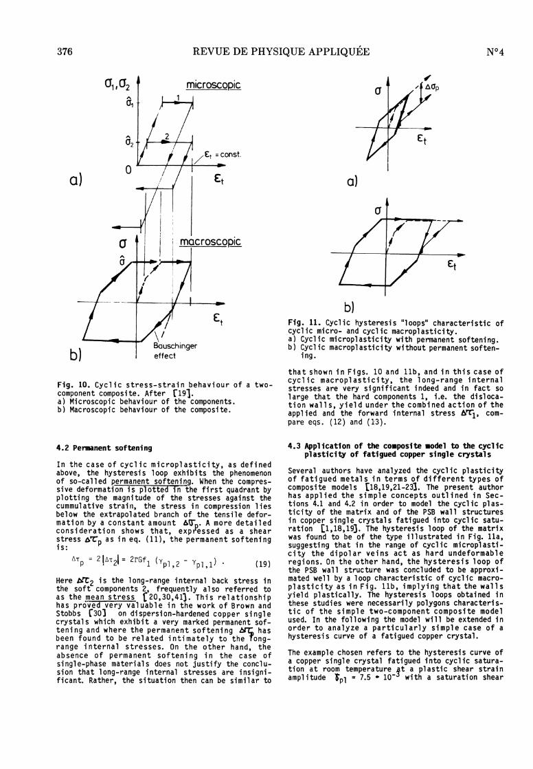
The representation of the "hypothetical" stress-strain behaviour of a two-component composite illus-trated in Fig. 5 can be extended easily to the caseof reverse loading, as shown in Fig. 10. Based onthe microscopic behaviour of the components(Fig. 10a), the macroscopic behaviour of the compo-site (Fig. lOb) is obtained under the assumptionthat no significant microstructural changes occurduring forward and reverse straining. This as-
sumption is approximately ful f i 11 ed in cycl i c sa-turation. The cyclic hysteresis curve obtained inFig. lOb exhibits the property of kinematic
hardening in association with a Bauschinger effect,i.e. a 1 oweri ng of the el asti c 1 i mi t after a rever-sal of the sense of deformation [431. The dashed"virgin" yielding curve illustrates the yielding ofthe composite which is considered to be i ni ti al lyfree of (long-range) internal stresses. Under theconditions stated, the cyclic hysteresis curve isrelated uniquely to the virgin monotonie yieldingcurve and can be obtained from the latter by multi-plication of the stresses and the strains by a
factor of two. Materials obeying this rule are saidto exhibit Masing behaviour [28].Fig. lOb refers to thé case where the (plastic)strain amplitude is so large that the hard componentyields plastically. In general, two cases must beconsidered in the case of a two-component composite,as illustrated in Figs. lla and llb ci 191. When!:t Tl/E, where E is Young’s modulus, a slim
sharply pointed hysteresis "loop", characteristic ofCyclic microplasticity is obtained (Fig, lla),whereas for larger amplitudes (e. t > 6-1/E) the hy-steresis loop assumes the "more rounded" shape cha-racteristic of cyclic macroplasticity (Fi g. llb).
376
Fig. 10. Cyclic stress-strain behaviour of a two-component composite. After rl9l.a) Microscopic behaviour of the components.b) Macroscopic behaviour of the composite.
4.2 Permanent softening
In the case of cyclic microplasticity, as definedabove, the hysteresis loop exhibits the phenomenonof so-called permanent softening. When the compres-sive deformation is plotted fin the first quadrant byplotting the magnitude of the stresses against thecummulative strain, the stress in compression liesbelow the extrapolated branch of the tensile defor-mati on by a constant amount 6U’, . A more detailedconsidération shows that, expressed as a shear
stress 6"t"p as in eq. (11), the permanent softeningis: ’
Here ÔFC2 is the long-range internal back stress inthe soft components 2, frequently al so referred toas the mean stress £20,30,413. This relationshiphas prôved very val uabl e i n the work of Brown andStobbs [30] on dispersion-hardened copper singlecrystals which exhibit a very marked permanent sof-teni ng and where the permanent sof teni ng fry hasbeen found to be related intimately to the ong-range internal stresses. On the other hand, theabsence of permanent softening in the case ofsingle-phase materials does not justify the conclu-sion that long-range internal stresses are insigni-ficant. Rather, the situation then can be similar to
Fig. 11. Cyclic hysteresis "loops" characteristic ofcyclic micro- and cyclic macroplasticity.a) Cyclic microplasticity with permanent softening.b) Cyclic macroplasticity without permanent soften-
ing.
that shown in Figs. 10 and llb, and in this case ofcyclic macroplasticity, the long-range internalstresses are very significant indeed and in fact solarge that the hard components 1, i.e. the disloca-tion walls, yield under the combined action of theapplied and the forward internal stress AT1’ com-
pare eqs. (12) and (13).
4.3 Application of the composite model to the cyclicplasticity of fatigued copper single crystals
Several authors have analyzed the cyclic plasticityof fatigued metal s in terms of différent types ofcomposite models [18,19,21-23). The present authorhas applied the simple concepts outlined in Sec-tions 4.1 and 4.2 in order to model the cyclic plas-ticity of the matrix and of the PSB wall structuresin copper single crystals fatigued into cyclic satu-ration [1,18,193. The hysteresis loop of the matrixwas found to be of the type illustrated in Fig. lla,suggesting that in the range of cyclic microplasti-city the dipolar veins act as hard undeformablerégions. On the other hand, the hysteresis loop ofthe PSB wall structure was concluded to be approxi-mated well by a loop characteristic of cyclic macro-pl as ti c i ty as in Fig. llb, implying that the wal 1 syield plastically. The hysteresis loops obtained inthese studies were necessarily polygons characteris-tic of the simple two-component composite modelused. In the following the model will be extended inorder to analyze a particularly simple case of ahysteresis curve of a fatigued copper crystal.
The example chosen refers to the hysteresis curve ofa copper single crystal fatigued into cyclic satura-tion at room temperature_lt a plastic shear strainamplitude ip1 = 7.5 - 10 with a saturation shear

377
stress amplitude roc = 29.8 MPa [441. At this
particular strain amplitude the dislocation micro-structure is completely deprived of the matrix andconsists exclusively of the PSB wall struc-ture [18,19,24,44]. Fig. 12 shows the hysteresisloop in a plot of shear stress’t versus plasticshear strain. 1. It is clear that in order tomodel such a smobthly curved hysteresis loop satis-factorily, a composite model with more than twocomponents is required. We therefore,al l ow for aspectrum of local flow stresses U7 in the wallsand c in the channel s, respectively. In the pre-sent case, this approach is considered to be adaptedbetter to the basically two-component nature of thedislocation wal l structure than the use of a proba-bility density function as in related models of
(polycrystal) cyclic plastici ty [22,23].We assume that the hysteresis loop obeys Masingbehaviour. Then the shear stress, measured from the
tip of the loop, is equal to 2’"t We denote thevolume fraction of material that is deformingplastically at a particular stress level byf 1 - fi (2*0. It is then easy to show that(tor r = 1) i n a pl ot of T versus el las i n
Fig. 12, the slope at a particular value of fpl(or’C) is given by
Hence
Fig. 12. Hystérésis curve 01 copper single crystalfatigued at ipi = 7.5 - 10 into cyclic saturation[18,44]. p
Thus, if fp1(203C4) is known, the hystérésis loop isobtained dry intégration of eq. (20). On the otherhand, for any given loop, fpl 1 can be determinedreadily by a graphical method according to eq. (21).In our case, f i is composed of two contributions,namely f ’ f rom the channel s and f 1 w from thewalls:
Fig. 13 illustrâtes the model. As the stress -isincreased (in tension or in compression), measuredfrom the tips of the hystérésis loop, frifand itscomponents fp1,c and f ) increase as a functionof 2’T as 1n#di’cated. ri’thé fonctions f andf w are separated sufficiently along thé stressaxis, then the résultant curve f i should exhibittwo points of inflection. Note tnat, in the simpletwo-component composite model (Sections 4.1,4.2),the functions f 1 c and fp1,w woul d be step-functions with a jumt) fr2m zero’to fc and fw at thediscrete stress values 2 zc and 2, respectively.
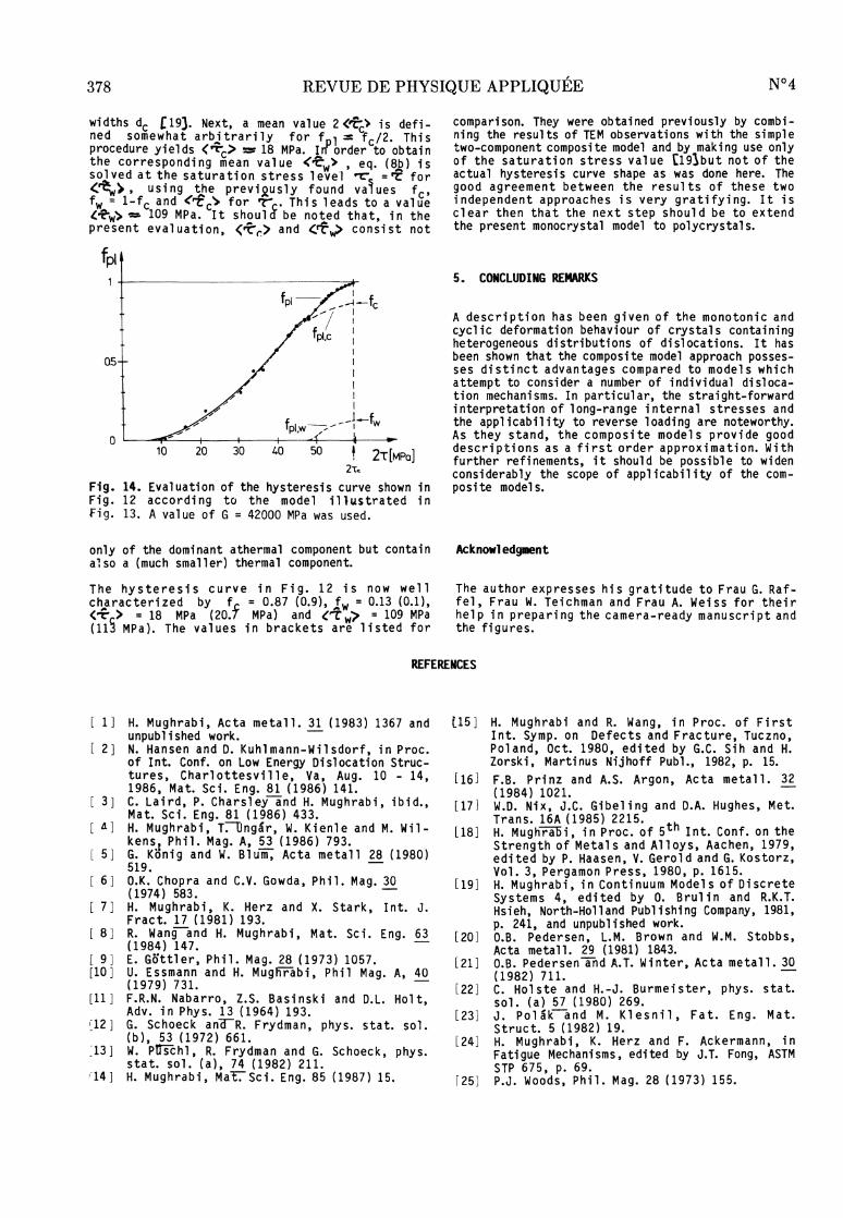
The result of the evaluation of the hysteresis loopshown in Fig. 12 al ong these 1 i nes is shown inFig. 14. The rather big scatter of the data pointsi n the range 2C s 35 MPa i s due to the inaccuracyof the evaluation of the very steep slope in thisstress range. Nonetheless, the curve drawn throughthe data points exhibits clearly the features expec-ted according to the model with one inflection pointat 2Tc?35 MPa and another one at 2’t::.: 48 MPa. Inour model, the second inflection point denotesroughly that external stress level at which theweakest walls begin to yield plastically. Hence thefact that such an inflection point exists providesfurther évidence that the wal 1 s yi el d pl asti cal lyand that the Eshelby factor r must be close to one,compare Section 3.1. One might expect naively thatthe second inflection point can be anticipated bymore inspection of the hysteresis loop. However, thehysteresis loop displays no discontinuity except atthe tips. At best, it can be stated that the stresslevel at which the second inflection point appearsis close to the point of intersection of the extra-pol ated curves that approximate the ascending andthe almost horizontal parts of the curve,cf. Fig. 12.
Fig. 13. Model showing how the volume fraction fplof plastically deforming material increases as afunction of increasing stress level.
The detailed evaluation is performed as follows. Thecurve extending up to 2U7= 45 MPa is considered to
represent essentially only the function fpl c. It isassumed that the value of f 1 obtained by tne extra-polation of this curve up tu the saturation stresslevel 2 Ts is identical with fc. A value of
fc -- 0.87 i s obtained. The functi on fp1,w i s foundby subtracti ng the extrapol ated curve fp1,c fromf . We note in passing that the shape of t E curvefp1,c correlates rather well with the curve obtainedf-ro1ii the distribution of the bowing stresses (ne-cessary to drive the screw segments along the chan-nels) based on the variations of the channel
378
wi dths dc [19]. Next, a mean val ue 2 ’t’c> i s defi-ned somewhat arbi trari ly for f 1 = fc/2. Thisprocédure yi el ds c> ~ 18 MPa. I order to obtainthe correspondi n9 mean value w>, eq. (8b) ilssol ved at the saturati on stress 1 eve‘l ’Tr = rf forw>, using the previ 2,usly found values fc,fw ; 1-fc and ri c’> for 7"": . Thi s 1 eads to a val uew> ~ 109 MPa. It shou18 be noted tha t, i n theprésent évaluation, c> and £r8p consist not
Fig. 14. Evaluation of the hysteresis curve shown inFig. 12 according to the model illustrated inFig. 13. A value of G = 42000 MPa was used.
only of the dominant athermal component but containalso a (much smaller) thermal component.
The hysteresis curve in Fig. 12 is now well
characterized by f = 0.87 (0.9), fw = 0.13 (0.1),
c> MPa). The values in brackets are listed for
comparison. They were obtained previously by combi-ning the results of TEM observations with the simpletwo-component composite model and by making use onlyof the saturation stress value [191but not of theactual hysteresis curve shape as was done here. Thegood agreement between the results of these twoindependent approaches is very gratifying. It isclear then that the next step should be to extendthe present monocrystal model to polycrystals.
5. CONCLUDING REMARKS
A description has been given of the monotonic andcyclic deformation behaviour of crystals containingheterogeneous distributions of dislocations. It hasbeen shown that the composite model approach posses-ses distinct advantages compared to models whichattempt to consider a number of individual disloca-tion mechanisms. In particular, the straight-forwardinterpretation of long-range internal stresses andthe applicability to reverse loading are noteworthy.As they stand, the composite models provide gooddescriptions as a first order approximation. Withfurther refinements, it should be possible to widenconsiderably the scope of applicability of the com-posite models.
Acknowledgment
The author expresses his gratitude to Frau G. Raf-fel, Frau W. Teichman and Frau A. Weiss for theirhe 1 pin prepari ng the camera-ready manuscript andthe figures.
REFERENCES
[1] H. Mughrabi, Acta metall. 31 (1983) 1367 andunpublished work.
[ 2 ] N. Hansen and D. Kuhlmann-Wilsdorf, in Proc.of Int. Conf. on Low Energy Dislocation Struc-tures, Charlottesville, Va, Aug. 10 - 14,1986, Mat. Sci. Eng. 81 (1986) 141.
[ 3] C. Laird, P. Charsley and H. Mughrabi, ibid.,Mat. Sci. Eng. 81 (1986) 433.
[ 4] H. Mughrabi, T. Ungár, W. Kienle and M. Wil-kens, Phil. Mag. A, 53 (1986) 793.
[ 5] G. König and W. Blum, Acta metall 28 (1980)519.
[ 6] O.K. Chopra and C.V. Gowda, Phil. Mag. 30(1974) 583.
[ 7] H. Mughrabi, K. Herz and X. Stark, Int. J.Fract. 17 (1981) 193.
[ 8] R. Wang and H. Mughrabi, Mat. Sci. Eng. 63(1984) 147.
[ 9] E. Göttler, Phil. Mag. 28 (1973) 1057.[10] U. Essmann and H. Mughrabi, Phil Mag. A, 40
(1979) 731. [11] F.R.N. Nabarro, Z.S. Basinski and D.L. Holt,
Adv. in Phys. 13 (1964) 193.[12] G. Schoeck and R. Frydman, phys. stat. sol.
(b), 53 (1972) 661.[13] W. Püschl, R. Frydman and G. Schoeck, phys.
stat. sol. (a), 74 (1982) 211.[14] H. Mughrabi, Mat. Sci. Eng. 85 (1987) 15.
[15] H. Mughrabi and R. Wang, in Proc. of FirstInt. Symp. on Defects and Fracture, Tuczno,Poland, Oct. 1980, edited by G.C. Sih and H.Zorski, Martinus Nijhoff Publ., 1982, p. 15.
[16] F.B. Prinz and A.S. Argon, Acta metall. 32(1984) 1021.
[17] W.D. Nix, J.C. Gibeling and D.A. Hughes, Met.Trans. 16A (1985) 2215.
[18] H. Mughrabi, in Proc. of 5th Int. Conf. on theStrength of Metals and Alloys, Aachen, 1979,edited by P. Haasen, V. Gerold and G. Kostorz,Vol. 3, Pergamon Press, 1980, p. 1615.
[19] H. Mughrabi, in Continuum Models of DiscreteSystems 4, edited by 0. Brulin and R.K.T.
Hsieh, North-Holland Publishing Company, 1981,p. 241, and unpublished work.
[20] O.B. Pedersen, L.M. Brown and W.M. Stobbs,Acta metall. 29 (1981) 1843.
[21] O.B. Pedersen and A.T. Winter, Acta metall. 30(1982) 711.
[22] C. Holste and H.-J. Burmeister, phys. stat.sol. (a) 57 (1980) 269.
[23] J. Polák and M. Klesnil, Fat. Eng. Mat.Struct. 5 (1982) 19.
[24] H. Mughrabi, K. Herz and F. Ackermann, in
Fatigue Mechanisms, edited by J.T. Fong, ASTMSTP 675, p. 69.
[25] P.J. Woods, Phil. Mag. 28 (1973) 155.

379
[26] J.C. Grosskreutz and H. Mughrabi, in Consti-tutive Equations in Plasticity, edited by A.S.Argon, MIT Press, Cambridge, Mass., 1975, p.
251.[27] H. Mughrabi, in Proc. of 3rd Int. Conf. on theStrength of Metals and Alloys, Cambridge, Vol.1, 1973, p. 407.
[28] G. Masing, Wissenschaftl. Veröffentl. aus demSiemens-Konzern 3 (1923) 231.
[29] J. D. Eshelby, Proc. Roy. Soc. London (A), 241(1957) 376.
[30] L.M. Brown and W.M. Stobbs, Phil. Mag. 23(1971) 1185.
[31] J. Lepinoux and L.P. Kubin, Phil. Mag. A, 51(1985) 675.
[32] A. Seeger, J. Diehl, S. Mader and H. Rebstock,Phil. Mag. 2 (1957) 323.
[33] P.B. Hirsch and T.E. Mitchell, Can. J. Phys.45 (1967) 663.
[34] T.Ungár, S. Tóth, J. Illy and I. Kovács, Actametall. 34 (1986) 1257.
[35] H. Mughrabi, S. Afr. J. Phys. 9 (1986) 62.[36] P.J. Jackson, Acta metall. 33 (1986) 449.[37] M.A. Morris and J.L. Martin, Acta metall. 32
(1984) 549. [38] A.S. Argon and S. Takeuchi, Acta metall. 29
(1981) 1877. [39] E. Orowan, in Internal Stresses and Fatigue of
Metals, edited by G.M. Rassweiler and W.L.Grube, Elsevier, Amsterdam, 1959, p. 59.
[40] U.F. Kocks, Phil. Mag. 13 (1966) 541.[41] L.M. Brown, Scripta metall. 11 (1977) 127.[42] Low Energy Dislocation Structures, Proc. of
Int. Conf., Charlottesville, Aug. 10 - 14,1986, edited by M.N. Bassim, W.A. Jesser, D.Kuhlmann-Wilsdorf and H.G.F. Wilsdorf, Mat.Sci. Eng. 81 (1986).
[43] J. Bauschinger, Mittheilungen aus dem Mecha-nisch-Technischen Laboratorium der K. Techn.Hochschule München 13 (1886) 1.
[44] H. Mughrabi, Mat. Sci. Eng. 33 (1978) 203.