discover - adronpmieng.com/images/coldwaxcastings.pdfa specially formulated wax is injected into a...
TRANSCRIPT

Welcome to Signicast, the investment casting industry leader. By working better, faster, and smarter than the competition, Signicast is able to provide you with:
1. Unprecedented Lead-Times for New Product Launches.
2. True Just-in-Time Delivery – Every Time.
3. The Highest Level of Quality.
4. Technologically-Advanced Processes and People.
Signicast is committed to satisfying customers like you. The company’s progressive management team is focused on harnessing emerging technologies to provide you with the highest-quality components at a competitive cost, on time, all the time.
The information contained in this brochure is intended to be a well-grounded starting point for both buyers and designers of investment castings. Many investment castings have special requirements that fall outside the scope of this brochure, or are not discussed. Signicast’s highly skilled Technical Sales and Engineering staff are available to consult with you regarding these needs and any other questions you may have.
The state-of-the-art advances rapidly in this business. And for more than half a century, Signicast has been one of the foremost companies advancing it. The experts at Signicast believe if something can be investment cast at all, they can find a way to do it. Let them prove it to you.
DISCOVER what sets Signicast dramatically apart from the competition. And how those differences directly benefit you.

BETTER
THE PROCESS ADVANTAGEInvestment casting is considered a “net shape” or “near net shape” process.
PROCESS COMPARISONS
Process ToleranceCapability
DesignFreedom
AlloySelection
SizeRange
LeadTime
VolumeCapability
SurfaceFinish
ToolCost
MachineCost
Investment Casting
Excellent Excellent Excellent Excellent Short All Good Average Low
Die Casting Excellent Excellent Poor Good Long High Good High Low
Powdered Metal
Excellent Fair Good Fair Long High Excellent Average Low
Stamping Excellent Good Fair Fair Short High Excellent High Low
Forging Fair Fair Good Fair Long High Fair High High
Sand Casting
Fair Good Good Good Short All Fair Low High
Fabrication Fair Fair Good Good Medium All Fair Low High
PREVIOUSLY FORGED• CA-40 stainless steel
• 90% of forged weight was machined away
RECREATED FROM A FORGING• 8620 alloy
• Cast internal spline
• Eliminated machining and broaching
INITIALLY SAND CAST• 4140 alloy
• Closer tolerances
• Eliminated machining
• Better cast finish
CONVERTED FROM A FABRICATION• 8620 alloy
• Reduced cost
• Improved quality
Almost any configuration can be investment cast.
The key to economical use of this process is to fully
utilize its flexible capabilities and incorporate as
much value added into the cast piece as possible.
No other metal working process provides the design
freedom and variety of alloy selections available with
investment casting.
A combination of Signicast’s advanced processes,
extensive automation, and proprietary technologies
allows Signicast to reduce a standard 12-week
industry lead time to one to four weeks. The result
is true Just-In-Time manufacturing capability.
INITIALLY MACHINED• CA-15 stainless steel
• 50% cost savings
HALF THE COST
This single-piece investment casting was
originally an assembly of two machined
components. Eliminating almost all
machining meant a 50% cost savings to
the customer.

INNOVATION AND FLEXIBILITYIn terms of quality, only a handful of the world’s investment casters come close to Signicast. Manufacturing throughput of less than one week is a
Signicast exclusive. Continuous Flow Manufacturing
– production runs non-stop, with the ultimate goal
of increasing plant efficiency, utilization and speed
– has revolutionized this industry, and Signicast
undisputedly reinvented the process.
Signicast’s goal is to assist customers in increasing
profits, without compromising quality, speed, or value.
How does Signicast do it? Through commitment to
advanced Continuous Flow and complete-to-print
manufacturing processes.
Rather than large batches moving from station to
station, an unbroken stream of individual components
flow continuously through the plant. Orders, even small
ones, go from entry to shipping without interruption.
Signicast’s unique proprietary software monitors
and controls the process on a real-time basis – 24
hours a day, seven days a week – ensuring schedules
remain 100% on time.
AUTOMATIC Signicast’s state-of-the-art manufacturing complex
in Hartford, Wisconsin is the showplace for complete-
to-print, Continuous Flow Manufacturing. The entire
complex – from top to bottom, one end to the other – is
designed to facilitate the efficient, unbroken flow of
product. The total size of the facility stands at more
than 650,000 square feet, with virtually every inch
of it devoted to helping customers maximize their
profitability.
Signicast’s Continuous Flow Manufacturing philosophy
affects every aspect of the process including
production, material handling, and information
processing. For example, Signicast uses an Automatic
Storage/Retrieval System in an innovative way: as a
material handling system. This eliminates time spent
looking for and moving work pieces.
JUST-IN-TIME (JIT) JIT manufacturing eliminates costly inventory by
enabling you to receive small quantities of product,
delivered frequently, according to your schedule.
INDUSTRY LEADING SPEEDAt Signicast’s Hartford complex, castings flow from
wax patterns to metal casting in just 4.3 days, (6 if
heat-treated, 8-10 if machined); tops in the industry
by far.
CONTINUOUS FLOW MANUFACTURINGContinuous Flow Manufacturing production runs
non-stop, increasing plant efficiency, utilization,
and speed. What typically takes others up to 12
weeks to do, Signicast does with its Continuous Flow
Manufacturing process in 5-10 days.
TOTAL VALUEWhether you’re looking for castings only, a complete-
to-print product – including machining, assembly,
and finishing – or other special services, Signicast
offers the best total value option and will continually
strive to find ways to improve processes. If there is
a better way of doing things, Signicast wants to be
the first to find and implement it.
At Signicast, high quality standards are met the
first time. There are no rework loops. Operators are
trained and empowered to identify and rectify quality
problems in-process.
REDUCED LABOR COSTSIndividual parts are automatically loaded into
hydraulic fixtures by robots, eliminating manual
loading/unloading and reducing set-up time.
Signicast can handle all your casting requirements,
from simple to complex. Large or small. Medium
or high volume. Jobs you’ve been told “can’t be
done.” Signicast continuously adapts to what the
customer wants. It’s Signicast’s responsibility to
make any component work within the framework of
the manufacturing plants.
For this shifter lever, only six manufacturing days are required
to complete the cast, heat treatment, mill, tap, and broach
operations.
Machined, assembled products – such
as this motorcycle foot peg mount – can
be supplied in two weeks or less, and
may include multiple castings, purchased
components, and multiple finishing
operations.

SIGNICAST FACILITIESSignicast consistently demonstrates its growth
philosophy. In 1972, the company moved to its current
Milwaukee site and has undergone nine expansions
there since that time. In 1993, Signicast continued
to grow and expand in Hartford, Wisconsin and
broke ground for the new corporate headquarters
and additional manufacturing complexes – making
the Hartford facility the most advanced of its kind
in the world. Signicast utilizes digital and robotic
automation designed and implemented in-house
by Signicast’s employees. Accelerated production
and a significant increase in casting quality, are the
result of unconventional thinking that has yet to be
imitated by any competitor.
Automated manufacturing systems, incorporating
robotics, eliminate material handling, making delivery
of your job faster than any other investment caster.
Many customers simply provide their production
schedules and Signicast develops a delivery program
to accommodate their work flow. Flexibility is critical
to success with JIT, and Signicast is equipped to
handle radical shifts in output when you are faced
with unexpected spikes in demand for your product.
Signicast incorporates the cellular manufacturing
philosophy. Each manufacturing module operates
independently, benefiting from the resources of a
large company and the flexibility of small teams.
YEARSIZE OF EXPANSION (SQ. FT.)
SIZE OF PLANT (SQ. FT.)
1972 - 11,360
1974 12,000 23,360
1975 1,550 24,910
1978 20,885 45,795
1984 10,120 55,915
1985 13,518 69,433
1988 7,920 77,353
1989 9,572 86,925
1990 11,579 98,504
MILWAUKEE COMPLEX
YEAR MODULESIZE OF EXPANSION (SQ. FT.)
SIZE OF PLANT (SQ. FT.)
1993 1 66,081 66,081
1995 Support 30,144 96,225
1997 2 76,372 172,597
2000 Support 21,309 193,906
2001 5 76,234 270,140
2003 3 82,654 352,794
2006 4 85,085 437,879
2012 Skywalk 9,148 447,027
2014 6 96,642 543,669
2014 7 110,890 654,559
HARTFORD COMPLEX
THE PROCESSMost any configuration can be investment cast. TOOLINGInitially, before the casting process begins, an
injection die is constructed to produce precise
wax patterns. All tooling is constructed of 7075
T6 aluminum at Signicast, Using CAD/CAM-driven
CNC milling and EDM machines. The injection die is
typically automated to produce patterns efficiently
and contains numerous controls and monitoring
devices to provide dimensionally consistent patterns.
For many high-volume applications, multi-cavity
dies are used.
WAX CELLSignicast Time: 14 hours
Traditional Time: 96 hours
PATTERN INJECTION
A specially formulated wax is injected into a die
to produce the pattern for the part. One pattern
must be made for each finished part to be cast.
This pattern is an exact replica of the metal part
to be produced, with allowances to compensate
for volumetric shrinkage during the process.
The pattern also includes one or more gates to guide
molten metal into the part during the solidification
process.
Signicast uses a patented system that was invented
and developed in-house for automatically distributing
semi-solid wax to the injection presses. It is unique in
the industry in its ability to control wax temperature
within +/- 1 degree Fahrenheit, which is important
for dimensional conformity.
Injecting wax at this temperature gives Signicast
several advantages. Since the wax is in a semi-solid
state when injected, the part undergoes less shrinkage
through the solidification process. In turn, the pattern
possesses better dimensional stability and resists
flash and cavitation (or sink) when cooling.
PATTERN ASSEMBLY
The individual wax patterns are assembled onto a
wax sprue to form a mold or tree. The number of
patterns assembled per mold varies, dependent upon
the size, weight, and configuration of a given part.
SHELL BUILDING CELLSHELL BUILDING
Signicast Time: 29 hours
Traditional Time: 168 hours

A ceramic mold is created by dipping or “investing” the
assembled patterns in liquid ceramic slurry, draining,
and then coating with a dry “stucco” sand. After
drying, this process is repeated several times until
a specified shell thickness results. The ceramic shell
ranges in thickness from 3/16” to 1/2” depending
on the size of the part being produced.
Advanced technology has allowed Signicast to
incorporate robotics into this operation. Signicast
utilizes sophisticated shell-drying technology to
reduce the total time to build a shell to one day from
the typical one-week average. Stable, economical,
environmentally safe water-based slurries are used.
DEWAXING AND FIRING
Signicast Time: 5 hours
Traditional Time: 48 hours
The wax is melted out with steam heat in an autoclave
and is recycled. Firing at 1800 degrees Fahrenheit
fuses the ceramic particles so the mold can withstand
the pressure and temperature of the molten metal.
It also removes all traces of organic materials. This
pre-heat improves the ability to cast fine detail. It
also improves the feed of liquid metal to compensate
for volumetric shrinkage.
CASTING CELL CASTING
Signicast Time: 18 hours
Traditional Time: 72 hours
Molten metal is poured into the pre-heated molds.
Typical pouring temperatures are approximately 3000
degrees Fahrenheit for steel. Before and after casting,
every melt is analyzed spectrographically to assure
compliance with customer specifications.
The investment casting process is unique in the broad
range of alloys that can be cast. Most any alloy can be
investment cast economically. Signicast specializes
in ferrous, air-melted alloys. Recommendations and
a guide to material properties in the Alloy Properties
section of this brochure will assist you in choosing
an economical alloy to meet your needs.
CLEANING
Signicast Time: 12 hours
Traditional Time: 72 hours
The ceramic shell is removed from the metal mold
with high-pressure jets of water. Any ceramic material
remaining in pockets or holes is dissolved away in a
hot chemical bath to ensure part cleanliness.
CASTING REMOVAL
Metal castings are removed from the runner using
abrasive wheel cutoff saws or a more economical
proprietary process.
FINISHING CELLGATE GRINDING
The material protrusion left from the gate, called the
gate witness, is ground to print specification using
a fixture for repeatability and efficiency.
FINISHED CASTINGS
Signicast Time: 20 hours
Traditional Time: 96 hours
The final cleaning operation is performed using a
blast with abrasive grit or steel shot. This blasting
produces a surface finish of 90-125 microinch Ra.
COMPLETE-TO-PRINT
Casting all features of a part for use in a final assembly
is the optimum use of the investment casting process.
However, some applications require more than can
be supplied by investment casting alone.
A cost savings is generated if the casting can be used
in the as-cast condition, but if premium tolerances,
surface finish, or coatings are required, Signicast can
supply complete-to-print components – adding only
one additional day to the overall lead time. Signicast
dedicates an entire facility solely to complete-to-
print manufacturing. The result is a high-quality,
high-value product that’s ready to ship straight from
our docks in as few as 4.3 days from start to finish.
NONDESTRUCTIVE TESTING
All sample castings are nondestructively tested in
order to establish first article quality. Nondestructive
Testing is generally not required on production
commercial castings. Listing of nondestructive tests
in order of increasing costs:
• Magnetic Particle
• Fluid Penetrant
• X-Ray
CERTIFICATION
• Chemical Certification – Can be provided at an
additional cost.
• Mechanical Property Certification – Adds to
cost. Consider a combination of Chemistry and
Hardness Certification instead. Marking each
casting with a heat number adds traceability,
but also adds an operation and cost.
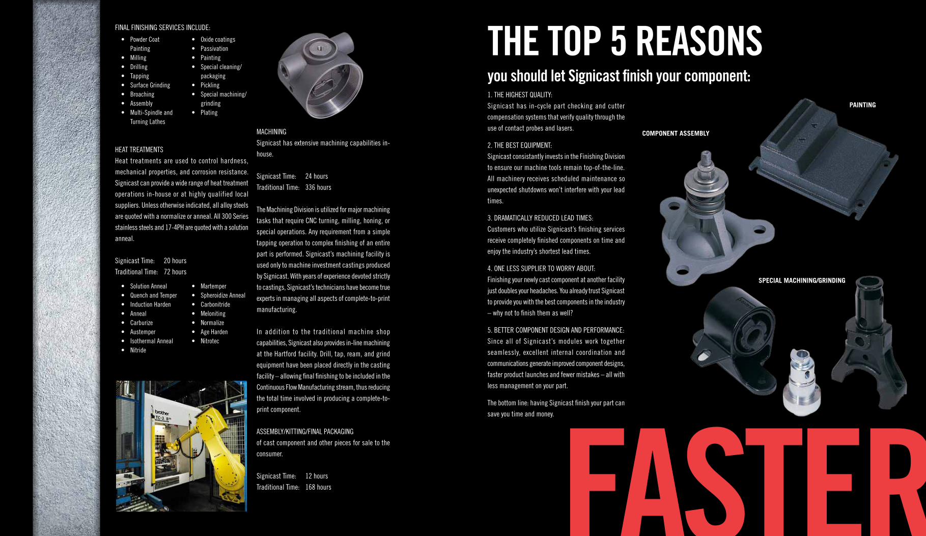
SPECIAL MACHINING/GRINDING
FASTER
FINAL FINISHING SERVICES INCLUDE:
HEAT TREATMENTS
Heat treatments are used to control hardness,
mechanical properties, and corrosion resistance.
Signicast can provide a wide range of heat treatment
operations in-house or at highly qualified local
suppliers. Unless otherwise indicated, all alloy steels
are quoted with a normalize or anneal. All 300 Series
stainless steels and 17-4PH are quoted with a solution
anneal.
Signicast Time: 20 hours
Traditional Time: 72 hours
MACHINING
Signicast has extensive machining capabilities in-
house.
Signicast Time: 24 hours
Traditional Time: 336 hours
The Machining Division is utilized for major machining
tasks that require CNC turning, milling, honing, or
special operations. Any requirement from a simple
tapping operation to complex finishing of an entire
part is performed. Signicast’s machining facility is
used only to machine investment castings produced
by Signicast. With years of experience devoted strictly
to castings, Signicast’s technicians have become true
experts in managing all aspects of complete-to-print
manufacturing.
In addition to the traditional machine shop
capabilities, Signicast also provides in-line machining
at the Hartford facility. Drill, tap, ream, and grind
equipment have been placed directly in the casting
facility – allowing final finishing to be included in the
Continuous Flow Manufacturing stream, thus reducing
the total time involved in producing a complete-to-
print component.
ASSEMBLY/KITTING/FINAL PACKAGING
of cast component and other pieces for sale to the
consumer.
Signicast Time: 12 hours
Traditional Time: 168 hours
• Powder Coat Painting
• Milling• Drilling• Tapping• Surface Grinding• Broaching• Assembly• Multi-Spindle and
Turning Lathes
• Oxide coatings• Passivation• Painting• Special cleaning/
packaging• Pickling• Special machining/
grinding• Plating
• Solution Anneal• Quench and Temper• Induction Harden• Anneal• Carburize• Austemper• Isothermal Anneal• Nitride
• Martemper• Spheroidize Anneal• Carbonitride• Meloniting• Normalize• Age Harden• Nitrotec
1. THE HIGHEST QUALITY:
Signicast has in-cycle part checking and cutter
compensation systems that verify quality through the
use of contact probes and lasers.
2. THE BEST EQUIPMENT:
Signicast consistantly invests in the Finishing Division
to ensure our machine tools remain top-of-the-line.
All machinery receives scheduled maintenance so
unexpected shutdowns won’t interfere with your lead
times.
3. DRAMATICALLY REDUCED LEAD TIMES:
Customers who utilize Signicast’s finishing services
receive completely finished components on time and
enjoy the industry’s shortest lead times.
4. ONE LESS SUPPLIER TO WORRY ABOUT:
Finishing your newly cast component at another facility
just doubles your headaches. You already trust Signicast
to provide you with the best components in the industry
– why not to finish them as well?
5. BETTER COMPONENT DESIGN AND PERFORMANCE:
Since all of Signicast’s modules work together
seamlessly, excellent internal coordination and
communications generate improved component designs,
faster product launches and fewer mistakes – all with
less management on your part.
The bottom line: having Signicast finish your part can
save you time and money.
PAINTING
COMPONENT ASSEMBLY
THE TOP 5 REASONS you should let Signicast finish your component:

GETTING TECHNICAL Technical service is a priority at Signicast. Early supplier involvement means Signicast’s in-house
technical staff and CAD capabilities are available to
help you, at your site, or here at Signicast, during the
formative stage of product design – improving the
way your existing component is produced, even if it
was previously manufactured by another cast process.
Customers appreciate the advantages provided by
Signicast’s extensive technical capabilities.
TECHNICAL SERVICESCAD – MAKING IT RIGHT THE FIRST TIME
Accurate detail of design geometry can be effectively
communicated through the use of three-dimensional
CAD data. Signicast is able to build high-quality wax
injection tooling using CAM-generated cutter paths
and CNC machines. Among the many benefits of
CAD tooling are:
• Reduced project time and a higher degree of
interpretation using customer CAD model.
• Higher efficiency in building complex tools.
In addition to tool-making, Signicast utilizes
simulation software to simulate solidification during
the casting process including: part geometry, gating,
sprue configuration, and temperature trials. The result
is a significant time savings by eliminating multiple
trials and achieving a high quality, repeatable process
the first time. Signicast has the expertise to transfer
data between CAD software systems.
RAPID PROTOTYPING
Prototyping can be an effective way to evaluate design
feasibility and productivity. However, at this stage of
a product’s life cycle, timing is essential. A delay of
weeks can result in lost market share.
FROM 17 PIECES TO ONE
This part was originally an assembly of 17 pieces.
The one-piece, 8.8 lb. investment casting – made
of WCB alloy – provided a tremendous savings
and eliminated dimensional variation found in the
weldment. This part was the result of Concurrent
Product Development between Signicast and the
customer.
SMARTER
Signicast plays a major role in expediting time-to-
market for new products, being well versed in utilizing
prototyping to simulate a production part in a minimal
time frame.
The best prototyping option to pursue is dependent on
the complexity of the component, the surface quality
desired, the time frame allowed, and the quantity of
pieces required.
The most effective options to prototype investment
castings include hard tooling, stereolithography (SLA
or STL), and Multi-Jet Modeling.
Signicast prototype experts can assist you in selecting
the best process for a particular situation. Cast metal
prototypes can be produced in as few as five days.
Consult Signicast to determine the shortest and most
economical path to your rapid prototyping needs.
The technology of rapid prototyping is changing and
improving continuously. Be assured, Signicast will
stay on top of all new developments.

DESIGN GUIDEDESIGN GOALSSignicast’s goal is to work in partnership with the
customer to produce high quality investment cast
components that will provide superior performance
and durability. This requires sound mechanical design
of the final component and the investment casting,
reliable process controls, consideration of marketplace
economic requirements, and clear communication
among all parties.
In any manufacturing process, the price of a product
will increase as the dimensional tolerance and
inspection criteria become more stringent. Early
involvement and input by Signicast’s technical staff
allows customers to overcome traditional casting
tolerance issues. This is accomplished by innovation
and technology to provide 100% conformance to
specifications as-cast, delivered on time, at the lowest
total cost. The most important guideline to remember
is to get Signicast involved early in the design stage.
SIZE AND WEIGHTPart size and weight are the most critical factors
in determining part cost because mold capacity is
limited by both size and weight. The more pieces
that can run on a mold, the lower the part cost.
Unnecessary mass should always be removed to
reduce part weight.
NUMBER OF GATESWhen possible, a part should be designed so that a
single gate can feed the part. This will generally yield
more pieces per mold and reduce the pour weight
per mold. Single gate feeding also enhances the
dimensional stability of a given part by providing a
directional solidification pattern.
CASTABILITYIf a design contains features that will raise scrap
or rework rates (and piece price), the Signicast
Estimating Engineer will recommend design
modifications to keep the piece price down.
LINEAR TOLERANCESThe investment casting process is capable of excellent
repeatability. As-cast process capability of +/- three
standard deviations when a single point location is
repeatedly measured is typically +/- .003 to +/- .004
per inch. However, tolerance capability is largely
influenced by part configuration. Symmetrical shapes
with uniform wall sections will solidify with much
less variation and distortion than non-symmetrical,
non-uniform shapes.
NORMAL LINEAR TOLERANCES
Normal linear tolerances for normal dimensions reflect
these three sources of variation:
• Prediction of Part, Shrinkage Factors (20%).
• Diemaker and Tooling, Tolerance (10%).
• Process Variation (70% of linear tolerance).
This variation is a combination of part configuration
effects that result in non-uniform shrinkage, and all
other process variation in producing a wax pattern,
ceramic mold, and the casting.
PREMIUM LINEAR TOLERANCES
All three sources of variation can be reduced by:
• Part redesign, including addition of tie bars,
ribs, and gussets to contain shapes.
• Tuning of wax injection tooling after the first
sample to meet nominal dimensions.
• Straightening/coining.
• Additional inspection/gaging.
• Machining.
All of these can assist in obtaining tighter-than-normal
tolerances. There are additional costs associated with
the last four bullets. Signicast will work with the
customer to meet the design requirements in the
most economical manner.
Premium tolerance capability can be achieved, but
must be considered on a part-by-part, dimension-
by-dimension basis. Signicast is capable of holding
+/- .002” in some features, although +/- .004” per
inch is a more typical premium cast tolerance.
Premium tolerances may add secondary operations
and cost to a part. It is important to designate tight
tolerances that are necessary to part function and
leave the rest open to normal linear tolerances.
GENERAL LINEAR TOLERANCES
What about dimensions that are on a drawing or CAD
file simply to describe the shape? These dimensions
can be most economically produced by applying a
broader General Linear Tolerance.
Another strategy that works well is to incorporate
these types of features into a 3-D CAD file for the part,
but not dimension them for inspection purposes. The
feature is then tooled per the design, but valuable
inspection and evaluation time is used only for
features important to the customer.
TOOLING• Signicast utilizes a system of tooling standards
to ensure uniform high quality design and
fabrication of wax injection dies which are
generally guaranteed for the life of the part.
• Type of tooling in order of least expensive tooling,
but highest piece price:
» MANUAL – Prototype or low volume
production work.
ENGLISH (inches) METRIC (millimeters)
Dimension Tolerance Dimension Tolerance
Up to .500” +/- .007 Up to 15mm +/- 0.20
Up to 1.000” +/- .010 Up to 25mm +/- 0.25
Up to 2.000” +/- .013 Up to 50mm +/- 0.35
Up to 3.000” +/- .016 Up to 75mm +/- 0.40
Up to 4.000” +/- .019 Up to 100mm +/- 0.50
Up to 5.000” +/- .022 Up to 125mm +/- 0.55
Up to 6.000” +/- .025 Up to 150mm +/- 0.65
Up to 7.000” +/- .028 Up to 175mm +/- 0.70
Up to 8.000” +/- .031 Up to 200mm +/- 0.80
Up to 9.000” +/- .034 Up to 225mm +/- 0.85
Up to 10.000” +/- .037 Up to 250mm +/- 0.95
Allow +/- .003” for each additional inch.
Allow +/- 0.1mm for each additional 25mm.
ENGLISH (inches) METRIC (millimeters)
Dimension Tolerance Dimension Tolerance
Up to 2.00” +/- .020 Up to 50mm +/- 0.50
Each Addtional 1.000”
+/- .010Each Addtional 25mm
+/- 0.25
MAXIMIZING RESULTS
Replacing machined surfaces with tightly controlled
cast features provided the customer with a
$500,000 annual savings. This was made possible
by Signicast’s “total component thinking” and a
complete understanding of the component part
and assembly.
» SEMI-AUTOMATIC – Parts that are too large
or fragile for fully automatic.
» FULLY AUTOMATIC – Higher volume parts
that can be ejected into a water bath.
It is less labor intensive and increases
productivity.
• More cavities mean higher tooling cost, but also
increases productivity.
• Configurations that do not allow metal cores
in tooling to be drawn due to undercuts or
complicated internal shapes must be treated
in one of the following ways:
» COLLAPSIBLE CORES – Lowest piece price,
higher tooling cost.
» LOOSE INSERTS – Best for low volume parts,
not an option for fully automatic tools.
» MULTI-PIECE WAX ASSEMBLIES – Best for
certain configurations, tolerance control
suffers along with increased part price.
» SOLUBLE WAX – Requires additional
die for the soluble wax and increased
labor for injection and removal of the
soluble pattern. Provides excellent
flexibility at moderate additional cost.
» PRE-FORMED CERAMIC CORES – High cost
for specialized shapes. Used instead of
soluble pattern because coring would not
be properly coated during shell building
process.
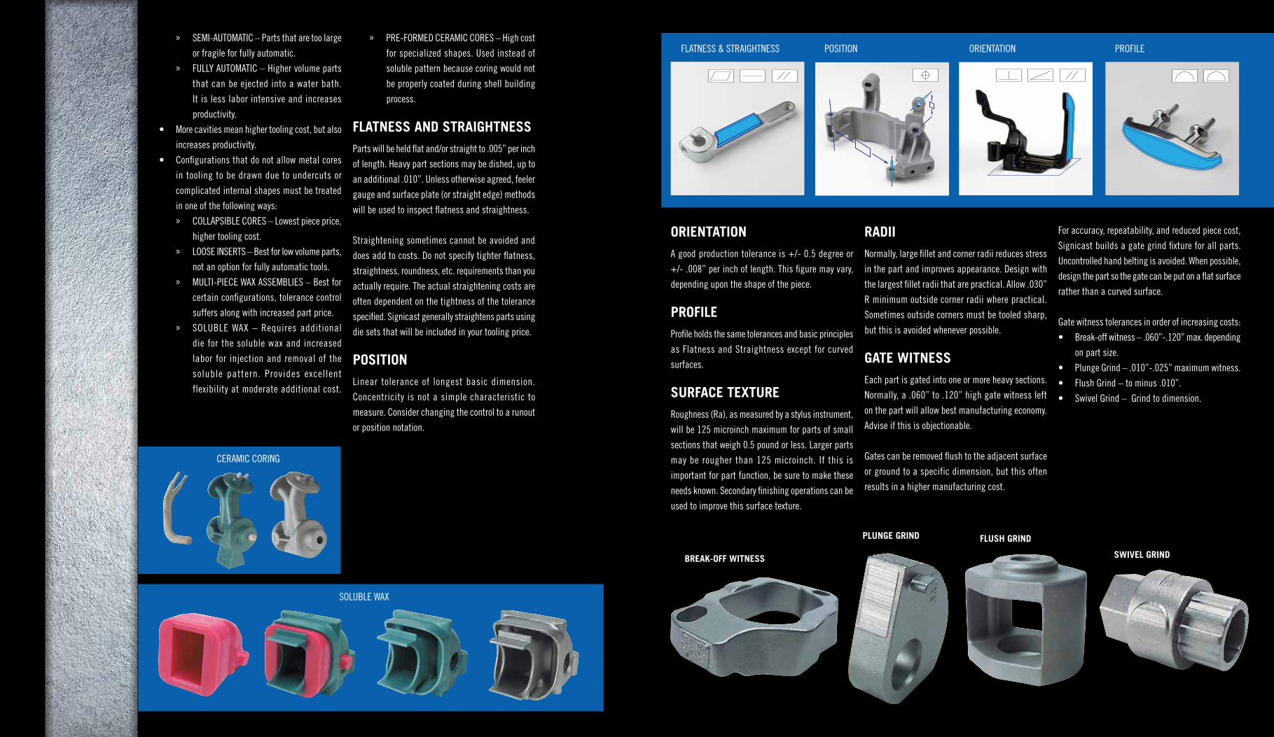
FLATNESS AND STRAIGHTNESSParts will be held flat and/or straight to .005” per inch
of length. Heavy part sections may be dished, up to
an additional .010”. Unless otherwise agreed, feeler
gauge and surface plate (or straight edge) methods
will be used to inspect flatness and straightness.
Straightening sometimes cannot be avoided and
does add to costs. Do not specify tighter flatness,
straightness, roundness, etc. requirements than you
actually require. The actual straightening costs are
often dependent on the tightness of the tolerance
specified. Signicast generally straightens parts using
die sets that will be included in your tooling price.
POSITIONLinear tolerance of longest basic dimension.
Concentricity is not a simple characteristic to
measure. Consider changing the control to a runout
or position notation.
ORIENTATIONA good production tolerance is +/- 0.5 degree or
+/- .008” per inch of length. This figure may vary,
depending upon the shape of the piece.
PROFILEProfile holds the same tolerances and basic principles
as Flatness and Straightness except for curved
surfaces.
SURFACE TEXTURERoughness (Ra), as measured by a stylus instrument,
will be 125 microinch maximum for parts of small
sections that weigh 0.5 pound or less. Larger parts
may be rougher than 125 microinch. If this is
important for part function, be sure to make these
needs known. Secondary finishing operations can be
used to improve this surface texture.
RADIINormally, large fillet and corner radii reduces stress
in the part and improves appearance. Design with
the largest fillet radii that are practical. Allow .030”
R minimum outside corner radii where practical.
Sometimes outside corners must be tooled sharp,
but this is avoided whenever possible.
GATE WITNESSEach part is gated into one or more heavy sections.
Normally, a .060” to .120” high gate witness left
on the part will allow best manufacturing economy.
Advise if this is objectionable.
Gates can be removed flush to the adjacent surface
or ground to a specific dimension, but this often
results in a higher manufacturing cost.
For accuracy, repeatability, and reduced piece cost,
Signicast builds a gate grind fixture for all parts.
Uncontrolled hand belting is avoided. When possible,
design the part so the gate can be put on a flat surface
rather than a curved surface.
Gate witness tolerances in order of increasing costs:
• Break-off witness – .060”-.120” max. depending
on part size.
• Plunge Grind – .010”-.025” maximum witness.
• Flush Grind – to minus .010”.
• Swivel Grind – Grind to dimension.
SOLUBLE WAX
CERAMIC CORING
SWIVEL GRINDBREAK-OFF WITNESS
FLUSH GRINDPLUNGE GRIND
POSITIONFLATNESS & STRAIGHTNESS ORIENTATION PROFILE

HOLESThrough holes (round or other shape) and slots may
be cast to:
Preformed ceramic coring may allow hole depths up
to 30 x diameter, at additional costs.
BLIND HOLESIn blind hole design, large corner radii blending from
the part surface to the hole are necessary to provide
adequate core strength. Bottoms of blind holes should
be full round or radiused as much as possible.
Blind holes may be cast to:
• Preformed ceramic cores can be used to allow
greater blind hole depths, but add significant
cost to the casting.
• Incorporate countersinks and counterbores with
the cast holes for improved economy.
WALL THICKNESSMinimum wall thickness and corner radii depend
upon part configuration and size. Small investment
castings may have walls cast to .030” thickness.
Medium to large castings require .060”-.100” walls
depending on the part geometry.
LETTERS/NUMBERS/LOGOS
Normally, raised letters or numbers in protective
depressed pads are easiest to manufacture. A .020”
high character on a depressed pad yields sharp,
castable features. Specify exact text and dimensions
of the figures. Logos can be investment cast to almost
any design.
SIZE MAX DEPTH
.040” - .080” 2 x hole diameter
.081" - .200" 3 x hole diameter
.201" - .400" 4 x hole diameter
.401" + 6 x hole diameter
SIZE MAX DEPTH BLENDINGCORNER RADII
.040" - .120" .5 x hole diameter .5 x hole diameter
.121" - .400" 1 x hole diameter .060” - .090”
.401" + 2 x hole diameter .091” - .180”
THROUGH HOLES / SLOTS CAST FEATURES: BLIND HOLES
SPLINES/GEARS/THREADSGear and thread profiles can be produced with
accuracies of +/- .004” per .5” of pitch. Longer
lengths or larger diameters can be held to normal
or premium linear tolerances as necessary.
GAGINGSignicast performs a 100% visual inspection of
all parts. If dimensional verification is required, a
sampling plan and process control is less expensive
than 100% gaging of each part.
• Important: Whenever custom gages are used,
there should be identical gages at Signicast
and at the customer’s facility.
• Fixed gages such as go-no-go are less expensive
to use than gages with dial indicators.
EXTERNAL SPLINES
SPLINED COUPLERS
SPUR GEARS
CAST THREADS
INTERNAL SPINES
REFERENCES:
Investment Casting Handbook, 1997 – Shows many applications, design data, alloy selection information, and quality control information.
Dimensioning and Tolerancing – ANSI Y 14.5 – An excellent engineering drawing standard published by the American Society of Mechanical Engineers.
This standard defines symbols, describes tolerance and datum methods, and contains valuable information to assist design of mating components.

ALLOY (ANSI EQUIVALENT) CONDITION TENSILE
STRENGTH (PSI)0.2% YIELDSTRENGTH (PSI)
% ELONGATION RANGE
HARDNESS RANGE OR MAX
A356 T6 34,000 24,000 3.5 70-105 Rb
ALUMINUM ALLOY
ALLOY CONDITION TENSILE STRENGTH (PSI)
0.2% YIELDSTRENGTH (PSI)
% ELONGATION RANGE
HARDNESS RANGE OR MAX
IC 1010 Annealed 50-60,000 30-35,000 30-35 50-55 Rb
IC 1020 Annealed 60-70,000 40-45,000 25-40 80 Rb
IC 1025 Annealed 63-73,000 42-47,000 25-35 80 Rb
WCB* Normalized 70-95,000 36-42,000 22-30 78-93 Rb
IC 1030Annealed 65-75,000 45-50,000 20-30 75 Rb
Hardened 85-150,000 60-150,000 0-15 20-50 Rc
IC 1035*Annealed 70-80,000 45-55,000 20-30 80 Rb
Hardened 90-150,000 85-150,000 0-15 25-52 Rc
IC 1045Annealed 80-90,000 50-60,000 20-25 100 Rb
Hardened 100-180,000 90-180,000 0-10 25-57 Rc
IC 1050Annealed 90-110,000 50-65,000 20-25 100 Rb
Hardened 125-180,000 100-180,000 0-10 30-60 Rc
IC 1060Annealed 100-120,000 55-70,000 12-20 25 Rc
Hardened 120-200,000 100-180,000 0-5 30-60 Rc
IC 4130Annealed - - - 100 Rb
Hardened 130-170,000 100-130,000 5-20 23-49 Rc
IC 4140*Annealed - - - 100 Rb
Hardened 130-200,000 100-155,000 5-20 29-57 Rc
IC 4150Annealed - - - 100 Rb
Hardened 140-200,000 120-180,000 5-10 25-58 Rc
IC 4330Annealed - - - 20 Rc
Hardened 130-190,000 100-175,000 5-20 25-48 Rc
IC 4340Annealed - - - 20 Rc
Hardened 130-200,000 100-180,000 5-20 20-55 Rc
IC 4620Annealed - - - 100 Rb
Hardened 110-150,000 90-130,000 10-20 20-32 Rc
IC 6150Annealed - - - 100 Rb
Hardened 140-200,000 120-180,000 5-10 30-60 Rc
IC 8620*Annealed - - - 100 Rb
Hardened 100-130,000 80-110,000 10-20 20-45 Rc
IC 8630Annealed - - - 100 Rb
Hardened 120-170,000 100-130,000 7-20 25-50 Rc
IC 8640Annealed - - - 20 Rc
Hardened 130-200,000 100-180,000 5-20 30-60 Rc
IC 52100*Annealed - - - 25 Rc
Hardened 180-230,000 140-180,000 1-7 30-65 Rc
ALLOY (ANSI EQUIVALENT) CONDITION TENSILE
STRENGTH (PSI)0.2% YIELDSTRENGTH (PSI)
% ELONGATION RANGE
HARDNESS RANGE OR MAX
CA-15* (410)Annealed - - - 100 Rb
Hardened 95-200,000 75-160,000 5-12 94 Rb-45 Rc
IC 416 (416)Annealed - - - 100 Rb
Hardened 95-200,000 75-160,000 3-8 94 Rb-45 Rc
CA-40 (420)Annealed - - - 25 Rc
Hardened 200-225,000 130-210,000 0-5 30-52 Rc
IC 431 (431)Annealed - - - 30 Rc
Hardened 100-160,000 75-105,000 5-20 20-40 Rc
IC 440A (440A)Annealed 30 Rc
Hardened 35-56 Rc
IC 440C* (440C)Annealed 35 Rc
Hardened 40-60 Rc
IC 17-4 (CB7CU-1)Annealed - - - 36 Rb
Hardened 150-190,000 140-160,000 6-20 34-44 Rc
CD-4MCuAnnealed 100-115,000 75-85,000 20-30 94-100 Rb
Hardened 135-145,000 100-120,000 10-25 29-32 Rc
ALLOY (ANSI EQUIVALENT) CONDITION TENSILE
STRENGTH (PSI)0.2% YIELDSTRENGTH (PSI)
% ELONGATION RANGE
HARDNESS RB MAX
CF-3 (304L) Annealed 70-85,000 40-50,000 35-50 90 Rb
CF-8 (304)* Annealed 70-85,000 40-50,000 35-50 90 Rb
CH-20 (309) Annealed 70-80,000 30-40,000 30-45 90 Rb
CK-20 (310) Annealed 60-75,000 30-40,000 35-45 90 Rb
CF-3M (316L)* Annealed 70-85,000 40-50,000 35-50 90 Rb
CF-8M (316)* Annealed 70-85,000 40-50,000 35-50 90 Rb
IC 316F (316F) Annealed 70-85,000 40-50,000 25-50 90 Rb
CF-16F (303) Annealed 65-75,000 30-35,000 35-45 90 Rb
CF-8C (347) Annealed 70-85,000 32-36,000 30-40 90 Rb
CN-7M (304L) Annealed 65-75,000 25-35,000 35-45 90 Rb
HK Annealed 65-75,000 35-45,000 10-20 100 Rb
ALLOY CONDITION TENSILE STRENGTH (PSI)
0.2% YIELDSTRENGTH (PSI)
% ELONGATION RANGE
HARDNESS RANGE OR MAX
Alloy B Annealed 75-85,000 50-60,000 8-12 90-100 Rb
Alloy C Annealed 75-95,000 45-55,000 8-12 90 Rb-25 Rc
CW-2M Annealed 72-87,000 40-45,000 20-30 75-90 Rb
Alloy X As-Cast 63-70,000 41-45,000 10-15 85-96 Rb
Monel A As-Cast 65-75,000 32-38,000 25-35 65-75 Rb
Monel SAnnealed 100-110,000 55-65,000 5-10 20-28 Rc
Hardened 120-140,000 85-100,000 0 32-38 Rc
Monel E As-Cast 65-80,000 33-40,000 25-35 67-78 Rb
ALLOY
H A R D N E S S
ANNEALED WITH SLOW COOL MAX. CYCLE ANNEAL MAX. HARDENED RANGE
IC A-2 20 Rc 27 Rc 47-60
IC A-6 100 Rb 48-59
IC D-2 35 Rc 50-59
IC H-11 100 Rb 46-55
IC H-13 100 Rb 45-53
IC 1-M-2 30 Rc 61-63
IC M-2 30 Rc 61-63
IC O-1 100 Rb 44-57
IC S-1 100 Rb 44-57
IC S-4 100 Rb 42-53
IC S-5 100 Rb 37-59
IC S-7 100 Rb 35-57
ALLOY CONDITION TENSILE STRENGTH (PSI)
0.2% YIELDSTRENGTH (PSI)
% ELONGATION RANGE
HARDNESS RC RANGE
3 As-Cast 48-53
6 As-Cast 37-45
31 As-Cast 105-130,000 75-90,000 6-10 20-30
93 As-Cast 60-65
ALLOY PROPERTIESChoose your material properties wisely.
CARBON AND LOW ALLOY STEELS
400 SERIES STAINLESS STEELS
300 SERIES STAINLESS STEELS
NICKEL BASED ALLOYS
TOOL STEELS
COBALT BASED ALLOYS
8620, 4130, 4140, WCB, and 1035 are best choices due to high volume.
CA-15 (410), 440C are best choices. Specify 416 if necessary for machinability.
CF-8M (316), CF-3M (316L), CF-8 (304) are best choices. Specify CF-16F (303) if necessary for machinability.
Blend of corrosion resistance and strength.
Costs vary widely depending on grade. S7, D2, H13 are commonly poured.
Choose based on end use.
Alloy CW2M is a good choice for corrosion resistance.
All grades pour well – choice is based on end use and cost.
Plain Carbon and Low Alloy Steels
400 Series Stainless Steels
300 Series Stainless Steels
17-4PH
Tool Steels
Monel
Nickel Based Alloys
Cobalt Based Alloys
ALLOY GRADEChoice of alloy listed from least to greatest cost.
MOS
T EX
PEN
SIVE
LEAS
T EX
PEN
SIVE
*Signicast recommends