disclaimers-space.snu.ac.kr/bitstream/10371/136776/1/000000144954.pdf · 2019-11-14 · synthesis...
TRANSCRIPT

저 시-비 리- 경 지 2.0 한민
는 아래 조건 르는 경 에 한하여 게
l 저 물 복제, 포, 전송, 전시, 공연 송할 수 습니다.
다 과 같 조건 라야 합니다:
l 하는, 저 물 나 포 경 , 저 물에 적 된 허락조건 명확하게 나타내어야 합니다.
l 저 터 허가를 면 러한 조건들 적 되지 않습니다.
저 에 른 리는 내 에 하여 향 지 않습니다.
것 허락규약(Legal Code) 해하 쉽게 약한 것 니다.
Disclaimer
저 시. 하는 원저 를 시하여야 합니다.
비 리. 하는 저 물 리 목적 할 수 없습니다.
경 지. 하는 저 물 개 , 형 또는 가공할 수 없습니다.

공학박사학위논문
Preparation of Functional Microporous Organic
Polymers and Their Applications for Heterogeneous
Catalysis and Dye Adsorption
기능성 마이크로기공성 유기고분자의 합성과 이의
불균질 촉매반응과 염료 흡착에의 활용
2017년 8월
서울대학교 대학원
재료공학부
김 종 길

- i -
Abstract
Preparation of functional microporous organic
polymers and their applications for heterogeneous
catalysis and dye adsorption
Jong Gil Kim
Department of Materials Science and Engineering
Seoul National University
Microporous organic polymers (MOPs) have many remarkable properties
such as high surface area, low density, microporosity, and physicochemical
stability. Various functional groups can be introduced to MOPs by the selection
of reactants and post-modification, which facilitates practical uses of MOPs in
various fields. However, most MOPs are obtained by insoluble powders
because of their highly crosslinked structures, which causes poor processability
of MOPs. In this study, various functional MOPs having shape-controlled
structures were prepared and used for heterogeneous catalysis and dye
adsorption.
Firstly, a MOP sponge was prepared using a homogenized electrospun

- ii -
nanofiber as the reinforcement. The Sonogashira-Hagihara coupling reaction of
2,5-dibromoaniline and 1,3,5-triethynylbenzene in a dispersion of homogenized
electrospun nanofibers (PVASi) produced the compressible MOP composite
with a core-shell structure (PVASi@TEDB-NH2). The polymer was uniformly
grown on the surface of the nanofibers because TEDB-NH2 had primary amino
groups that could form hydrogen bonds with the hydroxyl groups on the surface
of PVASi. PVASi@TEDB-NH2 showed an average density and a BET surface
area of 30.4 mg cm-3
and 447 m2g
-1, respectively. The composite sponge was
used for the removal of an organic dye dissolved in water. When
PVASi@TEDB-NH2 was manually compressed and released in an aqueous
methylene blue (MB) solution, the dye adsorption occurred rapidly.
Secondly, a microporous catalytic membrane based on a hypercrosslinked
polymer (HCP) was prepared. A HCP-based nanofibrous membrane was
synthesized via Friedel-Crafts reaction of 1,1’-bi-2-naphthol in the presence of
an aminated polyacrylonitrile (APAN) nanofibrous membrane as a substrate.
The HCP was uniformly grown on the surface of the APAN nanofiber, which
conferred a hierarchical porosity to the membrane. The HCP-based nanofibrous
membrane showed a good mechanical strength and microporosity with a
Brunaure-Emmett-Teller (BET) surface area of 375 m2 g
-1. The HCP-based
nanofibrous catalytic membrane (APAN-HCP-Pd) was prepared via the in-situ

- iii -
growth of palladium nanoparticles inside the membrane. The application of
APAN-HCP-Pd as a catalytic membrane was investigated for the reduction of
4-nitrophenol.
Thirdly, a compressible monolithic catalyst based on a MOP nanotube
sponge was prepared. The monolithic MOP sponge was synthesized via
Sonogashira-Hagihara coupling reaction between 1,4-diiodotetrafluorobenzene
and 1,3,5-triethynylbenzene in a co-solvent of toluene and TEA (2:1, v/v)
without stirring. The MOP sponge had an intriguing microstructure, where
tubular polymer fibers having a diameter of hundreds of nanometers were
entangled. It showed hierarchical porosity with a Brunauer-Emmett-Teller
(BET) surface area of 512 m2 g
-1. The MOP sponge was functionalized with
sulfur groups by the thiol-yne reaction. The functionalized MOP sponge
exhibited a higher BET surface area than the MOP sponge by 13 % due to the
increase in the total pore and micropore volumes. A MOP sponge-Ag
heterogeneous catalyst (S-MOPS-Ag) was prepared by in-situ growth of silver
nanoparticles inside the sulfur-functionalized MOP sponge by the reduction of
Ag+ ions. The catalytic activity of S-MOPS-Ag was investigated for the
reduction reaction of 4-nitrophenol in an aqueous condition. When S-MOPS-Ag
was compressed and released during the reaction, the rate of the reaction was
considerably increased. S-MOPS-Ag was easily removed from the reaction
- iv -
mixture owing to its monolithic character and was reused after washing and
drying.
Lastly, compressible polyimide composite having metal binding sites was
prepared by in situ polymerization inside a melamine sponge. 1,3,5-Tris(4-
aminophenyl)benzene and pyromellitic dianhydride were used as a triamine and
a dianhydride monomer, respectively, to construct the microporous framework,
and 5-amino-1,10-phenanthroline was used as a functional monomer. The
microporous polyimide containing phenanthroline groups (MPI-Phen) was
obtained as insoluble powders. However, when the polymerization was carried
out in the melamine sponge, MPI-Phen formed a coating layer on the sponge
skeletons. The melamine sponge/microporous polyimide composite (MS/MPI-
Phen) had an open cellular structure with a hierarchical porosity composed of
macropores between the sponge skeletons and meso- and micropores of the
MPI-Phen coating. It showed the higher compressive strength than the
melamine sponge, indicating the reinforcement by the microporous polymer.
The BET surface areas of MPI-Phen and MS/MPI-Phen were 723 m2g
-1 and
524 m2g
-1, respectively. Pd(II) ions were coordinated with the phenanthroline
groups of MS/MPI-Phen for heterogeneous catalysis (MS/MPI-Phen-Pd). The
catalytic activity of MS/MPI-Phen-Pd was evaluated for the Suzuki coupling
reaction between bromobenzene and phenylboronic acid.

- v -
Keywords: microporous polymer, electrospinning, sponge, membrane,
heterogeneous catalysis, dye adsorption.
Student Number: 2011-20631

- vi -
Contents Abstract ................................................................................................................ i
List of Schemes ................................................................................................... x
List of Tables ...................................................................................................... xi
List of Figures ................................................................................................... xii
Chapter I. Introduction ................................................................................... 1
I-1. Microporous Organic Polymers (MOPs) ......................................... 2
I-1-1. Introduction to MOPs ............................................................. 2
I-1-2. Preparation Methods of MOPs .............................................. 3
I-1-3. Potential Applications of MOPs ......................................... 13
I-2. Heterogeneous Catalysis with MOPs ........................................... 20
I-2-1. Introduction to Heterogeneous Catalysis .......................... 20
I-2-2. Porous Materials for Heterogeneous Catalysis ................. 22
I-2-3. Heterogeneous Catalysis with MOPs ................................. 23
I-3. Shape Control of MOPs ................................................................. 26
I-3-1. MOPs with Controlled Nanostructures ............................. 27
I-3-2. MOPs with Membrane Structures ..................................... 28
I-3-3. MOPs with Monolithic Morphologies with Hierarchical
Porosity ........................................................................................... 29
I-4. Electrospinning for Substrates...................................................... 32
I-4-1. Introduction to Electrospinning ......................................... 32
I-4-2. Electrospinning for Substrates of Functional Materials .. 35

- vii -
I-4-3. Electrospinning for 3D Nanofibrous Structures ............... 38
I-5. References ....................................................................................... 40
Chapter II. Homogenized Electrospun Nanofiber Reinforced Microporous
Polymer Sponge .......................................................................................... 49
II-1. Introduction .................................................................................. 50
II-2. Experimental ................................................................................. 52
II-3. Results and Discussion ................................................................. 56
II-3-1. Synthesis and the Morphology of the MOP-Nanofiber
Composites ...................................................................................... 56
II-3-2. Characterization of PVASi@TEDB-NH2 ......................... 63
II-3-3. Porosity of PVASi@TEDB-NH2 ........................................ 66
II-3-4. Application of PVASi@TEDB-NH2 as Organic Dye
Adsorbent ....................................................................................... 68
II-4. Conclusions ................................................................................... 74
II-5. References ..................................................................................... 75
Chapter III. Preparation of Microporous Polymer Membrane Containing
Pd Nanoparticles as a Catalytic Membrane ............................................ 81
III-1. Introduction ................................................................................. 82
III-2. Experimental ............................................................................... 84
III-3. Results and Discussion ................................................................ 88
III-3-1. Synthesis and Characterizations of a HCP-based
Microporous Membrane ............................................................... 88
III-3-2. Fabrication of a Pd-Containing Microporous Catalytic
Membrane and Its Catalytic Ability............................................. 98

- viii -
III-4. Conclusions .............................................................................. 102
III-5. References ................................................................................ 103
Chapter IV. Preparation of a Sulfur-functionalized Microporous Polymer
Sponge and In Situ Growth of Silver Nanoparticles: a Compressible
Monolithic Catalyst ................................................................................ 108
IV-1. Introduction ............................................................................. 109
IV-2. Experimental ............................................................................ 111
IV-3. Results and Discussion ............................................................ 115
IV-3-1. Synthesis and Characterization of a MOP Sponge .... 115
IV-3-2. Functionalization of a MOP Nanotube Sponge with Sulfur
Groups ......................................................................................... 119
IV-3-3. A Silver Decorated MOP Sponge as a Heterogeneous
Catalyst ....................................................................................... 126
IV-3-4. Catalytic Ability Evaluation of S-MOPS-Ag for the
Reduction of 4-Nitrophenol ....................................................... 129
IV-4. Conclusions .............................................................................. 134
IV-5. References ................................................................................ 134
Chapter V. A Hierarchically Porous Polyimide Composite Prepared by
One-Step Condensation Reaction inside a Sponge for Heterogeneous
Catalysis .................................................................................................... 139
V-1. Introduction ............................................................................... 140
V-2. Experimental ............................................................................. 142
V-3. Results and Discussion .............................................................. 145
V-3-1. Synthesis and Characterizations of MPI-Phen ............ 145

- ix -
V-3-2. Fabrication and Characterizations of MS/MPI-phen . 149
V-3-3. Pd2+
Chelating into MS/MPI-Phen for Suzuki Coupling
Reaction ...................................................................................... 154
V-4. Conclusions ................................................................................ 159
V-5. References .................................................................................. 159
국문요약 .................................................................................................... 165

- x -
List of Schemes
Scheme II-1. Synthesis of PVASi@TEDB-NH2 and PVASi@TEDB.
Scheme III-1. Schematic illustration of preparation of the HCP-based
microporous membrane.
Scheme IV-1. Reaction scheme for the synthesis of the MOP sponge and its
photo image.
Scheme IV-2. Thiol-yne modification of the MOP sponge and a possible
structure of S-MOPS.
Scheme V-1. Synthesis of a microporous polyimide containing phenanthroline
groups (MPI-Phen).
Scheme V-2. Suzuki coupling reaction between bromobenzene and
phenylboronic acid in the presence of MS/MPI-Phen-Pd.

- xi -
List of Tables
Table IV-1. Elemental compositions of the MOP sponge and S-MOPS
measured by elemental analysis.
Table IV-2. Porosity data of the MOP sponge and S-MOPS.
Table V-1. Suzuki coupling reaction results in different reaction solvents.

- xii -
List of Figures
Figure I-1. Examples of MOPs prepared by Sonogashira-Hagihara reaction.
Figure I-2. Examples of MOPs prepared by Yamamoto coupling reaction.
Figure I-3. Synthesis of MOP-1 by Suzuki coupling reaction.
Figure I-4. Synthesis of MOP-2 by oxidative coupling reaction
Figure I-5. Synthesis of MOP-3 by azide-alkyne cycloaddition.
Figure I-6. Examples of MOPs prepared by Friedel-Crafts reaction.
Figure I-7. Synthesis of MOP-4 by imide condensation reaction.
Figure I-8. Synthesis of (a) MOP-5, (b) MOP-6, and (c) MOP-7.
Figure I-9. Synthesis of MOP-8.
Figure I-10. Synthesis of (a) MOP-9, and (b) MOP-10.
Figure I-11. Synthesis of (a) MOP-11, (b) MOP-12, and (c) MOP-13 for CO2
adsorption.
Figure I-12. Synthesis of MOP-14 for iodine adsorption.
Figure I-13. Synthesis of MOP-15.
Figure I-14. Synthesis of MOP-16.
Figure I-15. (a) An example of the MOP having an optical property. (b)
Synthesis of MOP-17 for optical sensing.
Figure I-16. Illustration of structure of a heterogeneous catalyst.

- xiii -
Figure I-17. Synthesis of MOP-18 and the catalytic reaction of sulfides to
sulfoxides.
Figure I-18. Synthesis of MOP-19 and the catalytic reaction of the 4-
nitrophenol reduction.
Figure I-19. Synthesis of MOP-20 and the catalytic reaction of the acylation of
alcohols.
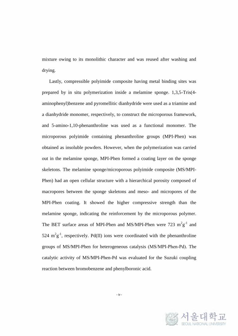
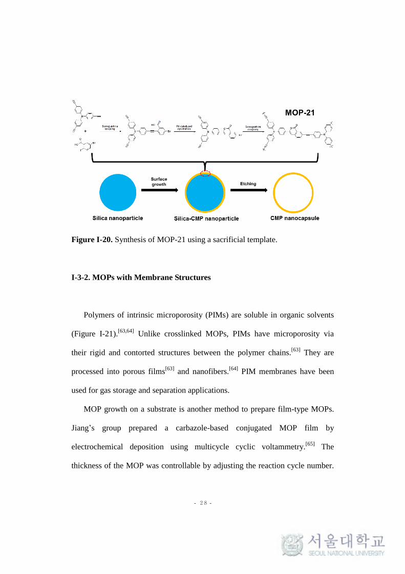
Figure I-20. Synthesis of MOP-21 using the sacrificial template.
Figure I-21. Synthesis of a soluble PIM.
Figure I-22. Synthesis of the MOP film on the functionalized gold film.
Figure I-23. Synthesis of MOP-22 having an aerogel structure.
Figure I-24. Illustration of the electrospinning setup.
Figure I-25. Illustration of some preparation methods of functional materials
based on electrospun substrates. (a) Blending electrospinning. (b) In-situ
growth on a nanofiber. (c) Core-shell electrospinning.
Figure I-26. Illusitration of the preparation of nanofibrous aerogels by the
freeze-drying method.
Figure II-1. SEM images of (a) TEDB and (b) TEDB-NH2. N2 adsorption-
desorption isotherms measured at 77 K for (c) TEDB and (d) TEDB-NH2.
Figure II-2. SEM images of PVASi (a) before and (b) after homogenization. (c)
TEM image and (d) the diameter distribution of as-spun PVASi.

- xiv -
Figure II-3. Photographs of (a) pieces of a PVASi mat in toluene and (b) a
dispersion of homogenized PVASi in toluene. (c) SEM image of individual
homogenized PVASi nanofibers at low magnification.
Figure II-4. (a), (b) SEM and (c), (d) TEM images of PVASi@TEDB-NH2. (e)
The diameter distribution of PVASi@TEDB-NH2 nanofibers.
Figure II-5. (a) EDS elemental analysis and (b) mapping of nitrogen for
PVASi@TEDB-NH2.
Figure II-6. (a) SEM and (b) TEM images of PVASi@TEDB.
Figure II-7. (a) Images of PVASi@TEDB-NH2 under loaded and unloaded
conditions (strain = 40%). (b) Compressive stress-strain curves (maximum
stress = 20, 40 and 60%) and (c) 10 cycles of loading-unloading test results of
PVASi@TEDB-NH2 (maximum strain = 40%).
Figure II-8. (a) Solid state 13
C CP/MAS NMR spectra, (b) FT-IR spectra, and
(c) PXRD patterns of TEDB-NH2 and PVASi@TEDB-NH2. (d) TGA
thermograms of PVASi, TEDB-NH2, and PVASi@TEDB-NH2.
Figure II-9. (a) N2 adsorption-desorption isotherms measured at 77 K and (b)
NLDFT pore size distributions of PVASi@TEDB-NH2 and TEDB-NH2.
Figure II-10. CO2 uptakes at 273 K of PVASi@TEDB-NH2 and TEDB-NH2.
Figure II-11. UV–vis spectra of the aqueous MB solution (initial concentration
= 5 x 10⁻⁵
M) measured after removing the dye by (a) compression and release

- xv -
process and by static adsorption (b) without stirring and (c) with stirring.
Figure II-12. (a) Photographs of aqueous MB solutions before (left) and after
(right) adsorption. (b) Recycle test results of PVASi@TEDB-NH2 for MB
adsorption by the compression and release process.
Figure II-13. Photographs of PVASi@TEDB-NH2 in water (a) before and (b)
after 10 cycles of compression and release.
Figure II-14. (a) Sequential photographs of the filtration process using a
PVASi@TEDB-NH2 syringe filter. (b) UV–vis spectra of the aqueous MB
solution before and after the filtration.
Figure II-15. UV-Vis spectrum of the aqueous MB solution measured after
filtration with a five times regenerated syringe filter.
Figure III-1. FT-IR spectra of PAN and APAN.
Figure III-2. SEM images of (a) the PAN membrane and (b) the APAN
membrane.
Figure III-3. The photographs of the PAN membrane, the APAN membrane,
and APAN-HCP.
Figure III-4. SEM images of (a), (b) APAN-HCP and (c), (d) the HCP.
Figure III-5. (a) FT-IR spectra of APAN, APAN-HCP, and the HCP. (b) Solid
state 13
C CP/MAS NMR spectra and (c) PXRD patterns of the HCP and APAN-
HCP. (d) TGA thermograms of APAN, APAN-HCP and the HCP.

- xvi -
Figure III-6. (a) N2 adsorption-desorption isotherms of APAN, the HCP, and
APAN-HCP. (b) NLDFT pore size distributions of the HCP and APAN-HCP.
Figure III-7. (a) SEM image of PAN-HCP. (b) Comparison of N2 adsorption-
desorption isotherms of APAN-HCP and PAN-HCP.
Figure III-8. (a) Photograph of the bent APAN-HCP. Tensile stress-strain
curves of (b) the APAN membrane and (c) APAN-HCP.
Figure III-9. (a) SEM image and (b) TEM image of APAN-HCP-Pd. (c) EDS
mapping of Pd for APAN-HCP-Pd. (d) High-resolution XPS spectrum of Pd3d
region of APAN-HCP-Pd.
Figure III-10. (a) UV-Vis spectra of the aqueous 4-NP solution (initial
concentration = 1 x 10⁻⁴
M) measured during the filtration process with APAN-
HCP-Pd. (b) Change in the 4-NP conversion efficiency of APAN-HCP-Pd
during recycling (1 set = six filtration cycles).
Figure IV-1. Solid state 13
C CP/MAS NMR spectrum of the MOP sponge.
Figure IV-2. (a) Images of the MOP sponge under compression and release
conditions. (b) Compressive stress-strain curves (maximum strain = 20 and
40 %) and (c) 10 cycles of loading-unloading test results of the MOP sponge
(maximum strain = 40 %).
Figure IV-3. (a), (b) SEM and (c), (d) TEM images of the MOP sponge.
Figure IV-4. (a) SEM and (b) TEM images of S-MOPS. (c) EDS mapping of

- xvii -
sulfur for S-MOPS.
Figure IV-5. (a) Compressive stress-strain curves (maximum strain = 20 and
40 %) and (b) 10 cycles of the loading-unloading test results of S-MOPS
(maximum strain = 40 %). (c) Comparison of hysteresis curves of the MOP
sponge and S-MOPS at 40 %.
Figure IV-6. (a) FT-IR spectra, (b) Solid state 13
C CP/MAS NMR spectra, (c)
PXRD patterns and (d) TGA thermograms of the MOP sponge and S-MOPS.
Figure IV-7. (a) N2 adsorption-desorption isotherms measured at 77 K and (b)
NLDFT pore size distributions of the MOP sponge and S-MOPS.
Figure IV-8. (a) SEM image and the photograph (inset) of S-MOPS-Ag. (b)
TEM image and (c) EDS mapping of silver atoms for S-MOPS-Ag. (d)
Diameter distribution of Ag nanoparticles inside S-MOPS-Ag.
Figure IV-9. (a) PXRD pattern of S-MOPS-Ag. (b) High-resolution XPS
spectrum of Ag3d region of S-MOPS-Ag.
Figure IV-10. (a) Compressive stress-strain curves (maximum strain = 40%)
and (b) N2 adsorption-desorption isotherms measured at 77 K of S-MOPS and
S-MOPS-Ag.
Figure IV-11. (a) UV-Vis spectra of the aqueous 4-NP solution (initial
concentration = 1 x 10⁻⁴
M) measured during the reaction with the compression
and release process. (b) Photographs of the 4-NP solution taken before and after

- xviii -
160 cycles of compression and release. UV-Vis spectra of the aqueous 4-NP
solution (initial concentration = 1 x 10⁻⁴
M) measured without the compression
and release process; (c) the reaction solution was not stirred and (d) the reaction
solution was stirred.
Figure IV-12. UV-Vis spectra of the aqueous 4-NP solution (initial
concentration = 1 x 10⁻⁴
M) measured during the reaction with the repeated
compression and release of S-MOPS.
Figure IV-13. Plots of - ln(Ct / C0) versus time during the catalytic reduction of
4-NP by S-MOPS-Ag under different reaction conditions. With the
compression-release process, the apparent rates constant (k) for the reaction =
7.61 x 10⁻³
s-1
. Without the compression and release process, k = 2.84 x 10⁻⁴
s-1
when the reaction solution was not stirred and k = 6.64 x 10⁻⁴
s-1
when the
reaction solution was stirred.
Figure IV-14. Change in the catalytic activity of S-MOPS-Ag during recycling.
Figure V-1. (a) FT-IR spectra, (b) Solid state 13
C CP/MAS NMR spectra and
(c) PXRD pattern of MPI-Phen. (d) High-resolution XPS spectra of N 1s from
MPI-Phen.
Figure V-2. N2 adsorption-desorption isotherms of MPI-Phen.
Figure V-3. (a) Images of the melamine sponge (left) and MS/MPI-Phen (right).
(b) Cross-sections of MS/MPI-Phen.

- xix -
Figure V-4. SEM images of (a), (b) the melamine sponge, (c), (d) MPI-Phen
and (e), (f) MS/MPI-Phen.
Figure V-5. TGA thermograms of the melamine sponge, MPI-Phen and
MS/MPI-Phen.
Figure V-6. (a) N2 adsorption-desorption isotherms of the melamine sponge,
MPI-Phen, and MS/MPI-Phen. (b) NLDFT pore size distributions of MPI-Phen
and MS/MPI-Phen.
Figure V-7. (a) Images of MS/MPI-Phen under compressed and released
conditions (strain = 60 %). Compressive stress-strain curves (maximum strain =
20, 40 and 60 %) of (b) the melamine sponge and (c) MS/MPI-Phen.
Figure V-8. (a) SEM image and (b) EDS spectrum of MS/MPI-Phen-Pd. (c)
EDS mapping of Pd atom for MS/MPI-Phen-Pd. (d) High-resolution XPS
spectrum of Pd 3d region of MS/MPI-Phen-Pd.

- 1 -
Chapter I.
Introduction

- 2 -
I-1. Microporous Organic Polymers (MOPs)
I-1-1. Introduction to MOPs
Porous materials are substances containing inner pores. According to the
IUPAC classification, pores are identified by their size.[1]
Macropores are pores
with diameters exceeding 50 nm, mesopores have diameters between 2 and 50
nm, and micropores have diameters of less than 2 nm. Among these, the
presence of micropores inside materials is known to contribute to a high
internal surface area and to allow the adsorption of minute materials.[2,3]
This
feature can be used in applications such as gas storage and separation, the
adsorption of small molecules, catalysis, and sensors. [2,4,5]
Generally, the adsorption of gases such as nitrogen, argon and carbon
dioxide at a specific temperature is used to measure the porosity of porous
materials.[6]
At a low gas pressure, gas molecules initially fill the inside of the
micropores. Subsequently, when the pressure increases, multilayer adsorption
and capillary condensation of the gas molecules occurs at the mesopores and
macropores.[1,7,8]
Surface areas measured by the adsorption of gasses are
commonly calculated by a Brunauer-Emmitt-Teller (BET) analysis, which is
based on the monolayer capacity of porous materials.[1]

- 3 -
Various types of materials containing micropores have been explored such
as carbon materials,[9,10]
zeolites,[11]
metal-organic frameworks (MOFs),[12,13]
and microporous organic polymers (MOPs) for specific applications.
Specifically, MOPs have attracted considerable attention due to their
remarkable properties. In general, MOPs are synthesized through the covalent
crosslinking between selected building blocks. They have highly interconnected
three-dimensional (3D) rigid networks, which imparts a high surface area,
microporosity, and chemical and thermal stability to the polymers.[2,5,14]
Various types of chemical reactions and building blocks can be used to
construct porous polymer networks, increasing the flexibility of structural
designs and allowing the realization of desirable pore properties. Moreover,
MOPs are easily functionalized by the choice of building blocks and by post-
modifications.[5,15]
To fabricate MOPs with desired properties, various chemical
reactions have been researched.
I-1-2. Preparation Methods of MOPs
MOPs can be prepared using various chemical reactions including metal-
catalyzed reactions and condensation reactions.

- 4 -
Metal-catalyzed coupling reactions are widely used to prepare hyper-
crosslinked polymers with conjugated structures.[2,5]
Since Cooper’s group
synthesized the first conjugated microporous polymers (CMPs) in 2007, various
types of coupling reactions have been used to fabricate MOPs with controlled
molecular structures.
The Sonogashira-Hagihara reaction is a typical coupling reaction for the
synthesis of MOPs. Figure I-1 shows several MOPs synthesized by the
Sonogashira-Hagihara reaction.[16,17]
Figure I-1. Examples of MOPs prepared by the Sonogashira-Hagihara reaction.
The Yamamoto coupling reaction is another coupling reaction that has been
used for the synthesis of MOPs with a high surface area. Zhou’s group prepared
tetrahedral monomers-based MOPs using the Yamamoto coupling reaction

- 5 -
(Figure I-2).[18]
The polymer showed a very high BET surface area above 5000
m2g
-1 and had strong CO2, H2 and CH4 uptake properties.
Figure I-2. Examples of MOPs prepared by the Yamamoto coupling reaction.
Jiang’s group prepared a polyphenylene-based MOP (MOP-1) by the
Suzuki coupling reaction (Figure I-3).[19]
Owing to its conjugated structure and
high surface area, MOP-1 showed rapid and efficient light energy flow
properties.

- 6 -
Figure I-3. Synthesis of MOP-1 by the Suzuki coupling reaction.
Several groups synthesized MOPs by an oxidative coupling reaction. Given
that the oxidative coupling reaction requires relatively inexpensive catalysts
such as FeCl3, it is a cost-effective reaction compared to other coupling
reactions which require novel metal catalysts such as palladium. Han’s group
reported various types of MOPs using the oxidative coupling reaction.[20,21]
A
carbazole-based MOP (MOP-2) showed a high BET surface area above 2000
m2g
-1 and high gas selectivity toward CO2 over N2 (Figure I-4).

- 7 -
Figure I-4. Synthesis of MOP-2 by the oxidative coupling reaction
MOP-3 was synthesized by azide-alkyne cycloaddition, also known as a
“Click reaction” (Figure I-5).[22]
Click chemistry is suitable for the preparation
of nitrogen-rich MOPs due to the presence of triazole units.
Figure I-5. Synthesis of MOP-3 by azide-alkyne cycloaddition.

- 8 -
The Friedel-Crafts reaction is an efficient way to fabricate hypercrosslinked
microporous polymers. Diverse types of aromatic group-containing monomers
and polymers can be used for the Friedel-Crafts reaction (Figure I-6).[14,23]
Figure I-6. Examples of MOPs prepared by the Friedel-Crafts reaction.
Condensation reactions have been also widely used to synthesize
microporous polymers. Unlike metal-catalyzed reactions, most condensation
reactions are conducted without a metallic catalyst, providing cost and
environment advantages.

- 9 -
Imide condensation is a representative reaction which can be used to
prepare thermosetting resins. Microporous polyimides have attracted much
research interest because of their rigid heteroaromatic frameworks and high
thermal and chemical stability levels. Moreover, they have numerous nitrogen
and oxygen atoms, making them beneficial for many applications, such as CO2
adsorption and metal ion capturing.[24,25]
Figure I-7 shows an example of
microporous polyimide (MOP-4), which exhibited a BET surface area of 1454
m2g
-1. [24]
Figure I-7. Synthesis of MOP-4 by the imide condensation reaction.
Imine condensation between aldehyde and amine groups is also used to
create rigid microporous networks without a catalyst. Several groups have

- 10 -
investigated imine-linked MOPs (Figure I-8a).[26,27]
MOP-5 showed good CO2
capture capacity because of the presence of many nitrogen atoms. Müllen’s
group prepared a melamine-based MOP (MOP-6) via Schiff-base chemistry
(Figure I-8b).[28]
MOP-6 showed a BET surface area of 1377 m2g
-1. MOPs
based on benzimidazole were synthesized using aldehyde and ortho-diamine
monomers. El-Kaderi’s group reported MOP-7, which had a BET surface area
of 1172 m2g
-1 (Figure I-8c).
[29]

- 11 -
Figure I-8. Synthesis of (a) MOP-5, (b) MOP-6, and (c) MOP-7.
Kanatzidis’s group synthesized MOP aerogels using various types of
phenolic molecules and aldehydes (Figure I-9).[30]
The BET surface area of
MOP-8 was nearly 1230 m2g
-1. Due to their abundant hydroxyl functional
groups, phenolic-resin based MOPs showed strong potential for CO2 uptake and
metal ion chelating applications.[30,31]

- 12 -
Figure I-9. Synthesis of MOP-8.
MOP-9 was synthesized by the thiol-yne reaction with an aid of a thermal
initiator (Figure I-10a).[32]
MOP-9 showed a BET surface area of 576 m2g
-1 and
could support gold nanoparticles for catalysis.
A catalyst-free pericyclic reaction such as Diels-Alder reaction has been
used to synthesize reversibly-crosslinked porous polymers (Figure I-10b).[33]
MOP-10 was structurally reconstructed by heating and showed a BET surface
area of 1038 m2g
-1.

- 13 -
Figure I-10. Synthesis of (a) MOP-9 and (b) MOP-10.
I-1-3. Potential Applications of MOPs
MOPs can be used practically in various applications. The adsorption and
separation of specific gases are typical applications. Recently, carbon dioxide
(CO2) has been pointed out as the major cause of the greenhouse effect. Most
CO2 is produced by the combustion of fossil fuels, such as by power plants and
automobiles.[34]
Therefore, CO2 capture and storage from post-combustion

- 14 -
gases are significant challenges. In general, the post-combustion gas produced
by a power plant is composed of nitrogen (N2) (> 70%) and CO2 (10-15 %).[35]
Meanwhile, methane (CH4) is another abundant alternative energy source. It has
environmental advantages compared to other fossil fuels due to its the high ratio
of hydrogen to carbon. However, natural gas contains impurities such as CO2,
N2, and other hydrocarbons and an additional purification process is
required.[35,36]
For these reasons, materials for the CO2 capture must have not
only high CO2 adsorption capacities but also good selectivity for CO2 over
other gases such as N2 and CH4.
Because a CO2 molecule has a large quadrupole moment,[37]
polar groups in
MOPs can improve the degree of affinity for CO2 molecules. The definite
interaction between CO2 and functional groups has been calculated according to
density function theory.[38]
A benzene groupshows a binding energy of only -
5.57 kJ mol-1
with CO2. However, the binding energy of benzene with CO2
increases significantly by the functionalization with a polar group. For example,
the binding energy between benzene with an amine group and CO2 is -13.34 kJ
mol-1
. MOPs have good potential as a physical adsorbent for CO2 capture and
storage due to their high degree of porosity and the possibility of surface
functionalization.[5]

- 15 -
Figure I-11 shows examples of MOPs with high CO2 storage and separation
properties. MOP-11 with a nitrogen-rich structure was synthesized by the imine
condensation reaction.[39]
It showed a high BET surface area (1740 m2 g
-1), high
CO2 uptake level (26.7 wt%, 273 K, 1 bar) and moderate selectivity for CO2/N2
(14.5) and CO2/CH4 (11.0) adsorption.
MOP-12 was synthesized by post-functionalization to improve CO2 uptake
and selectivity.[40]
After amine modification, the surface area of this MOP
decreased from 1249 m2 g
-1to 554 m
2 g
-1. However, the CO2 uptake of the MOP
increased from 11.0 wt% to 12.8 wt%. Specifically, the selectivity values for
CO2/N2 and CO2/CH4 were greatly increased, from 12 to 38 and from 3 to 9,
respectively.
MOP-13 was synthesized by a Friedel-Crafts reaction between cyanuric
chloride and ferrocene.[41]
MOP-13 had a BET surface area of 875 m2 g
-1 and
showed good CO2 uptake and CO2/N2 selectivity of 16.9 wt% (273 K, 1 bar)
and 107, respectively. The nitrogen-rich MOP skeleton and Fe ions inside the
framework contributed to the high CO2 adsorption.

- 16 -
Figure I-11. Synthesis of (a) MOP-11, (b) MOP-12, and (c) MOP-13 for CO2
adsorption.
MOPs can be used for the adsorption of harmful volatile compounds. Li’s
group synthesized a thiophene-containing MOP (MOP-14) for the adsorption of
volatile iodine (Figure I-12).[42]
Owing to its high porosity and electron-rich
thiophene groups, MOP-14 showed iodine uptake of 222 wt% within 3 hours.

- 17 -
Figure I-12. Synthesis of MOP-14 for iodine adsorption.
Deng’s group reported MOP-15, which had outstanding adsorption
properties for organic dyes and metal ions (Figure I-13).[43]
The maximum
adsorption capacities of Congo red dye, methyl blue dye, and Pb2+
ions were
1376.7 mg g-1
, 629.1 mg g-1
and 826.1 mg g-1
, respectively.

- 18 -
Figure I-13. Synthesis of MOP-15.
Several conjugated MOPs have recieved attention for energy applications.
For example, an aza-fused CMP (MOP-16) was synthesized for supercapacitive
energy storage (Figure I-14).[44]
Because of its well-defined conjugated
microporous structure, MOP-16 showed remarkable capacitance and energy
density levels as well as good recyclability. Jiang’s group prepared a
hexaazatrinaphthalene CMP (HATN-CMP) for lithium-battery energy
applications.[45]
It had redox-active units and open nanopores, showing high
energy capacity and good cycle stability.

- 19 -
Figure I-14. Synthesis of MOP-16.
Fluorescent conjugated MOPs have the potential for use in small molecular
sensing applications. For example, Liu’s group synthesized an azine-linked
MOP (MOP-17) by means of solvothermal condensation (Figure I-15b).[46]
MOP-17 showed moderate microporosity (570 m2g
-1) and high luminescence
efficiency. Owing to the abundant hydroxyl groups on the pore wall, it
efficiently adsorbed Cu2+
ions, leading to the fluorescence quenching.

- 20 -
Figure I-15. Synthesis of MOP-17.
I-2. Heterogeneous Catalysis with MOPs
I-2-1. Introduction to Heterogeneous Catalysis
Heterogeneous catalysts have attracted considerable attention from the
chemical industry. In general, heterogeneous catalysts are composed of an
active phase and an insoluble support where active sites are dispersed (Figure I-
16).[47,48]
Compared to homogeneous catalysts, heterogeneous catalysts have
some advantages. They can be removed by simple methods such as filtration

- 21 -
and centrifugation from reaction mediums, which increases the efficiency of the
process and reduces the additional cost.[47,48]
Heterogeneous catalysts can be
used for continuous flow processes, thus expanding the applications of
catalysts.[48]
Moreover, some heterogeneous catalysts show catalytic properties
superior to those of homogeneous catalysts due to the site-isolation and
constraint effects.[49]
Figure I-16. Illustration of structure of a heterogeneous catalyst.
Choice of support materials for heterogeneous catalysts is important to
optimize their catalytic properties. First, support materials should be stable
during reaction processes. Secondly, active sites should be uniformly dispersed
on the surfaces of the supports to maximize the catalytic efficiency.[50,51]
Finally,

- 22 -
supports should immobilize active species tightly to prevent them leaching
during reactions.[9,47,49]
I-2-2. Porous Materials for Heterogeneous Catalysis
Porous materials are a prime candidate as a support for heterogeneous
catalysts. They have large surface areas and high porosity, which facilitates the
easy diffusion of reactants to active sites.[49,50]
Therefore, various types of
porous materials have been researched for heterogeneous catalysis.
Zeolites are crystalline microporous inorganic materials. Zeolites are
composed of aluminosilicates, and are used for oil refining and
petrochemistry.[52]
Some metal cations can be incorporated into zeolites by ion-
exchange processes, which can act as catalytic active species.[11,52]
Zeolites
containing metal cations have been used as heterogeneous catalysts for the
catalytic oxidation of volatile organic compounds.[11]
Porous carbons have been used as substrates for heterogeneous catalysts due
to their high surface area, controllable morphologies, and good chemical
stability.[9]
In general, metal nanoparticles are dispersed inside porous carbons
as active species. By doping heteroatoms into the surface of porous carbons, the
catalytic properties and the stability of heterogeneous catalysts can be

- 23 -
improved.[9]
Porous carbons can be also used for electrochemical catalysis due
to their high electrical conductivity.[9,53]
Mesoporous silicas are prepared by a sol-gel reaction in the presence of a
micelle. Mesoporous silicas have many advantages for heterogeneous catalysts,
such as large surface areas, tunable pore sizes, high thermal stability levels, and
a low price.[47,50]
Moreover, their pore surface can be modified by co-
condensation and post-grafting methods.[47]
Various active species including
organic groups, metal ions, and metal nanoparticles can be immobilized onto
mesoporous silicas.[47,50]
I-2-3. Heterogeneous Catalysis with MOPs
Compared to carbon and inorganic materials, MOPs have many advantages
when used as a support for heterogeneous catalysis, such as high porosity levels,
robust molecular structures, good structural stability and functionalization
capabilities.[5,51,54]
Diverse types of active species have been immobilized in
MOPs by numerous methods.
MOP-metal ion complexes are composed of microporous polymers with
functional groups and catalytic metal ions. Metal ions are homogeneously
coordinated with the functional groups of the polymers. Jiang’s group

- 24 -
synthesized a metalloporphyrin-based MOP (MOP-18) by the Suzuki coupling
reaction (Figure I-17).[55]
MOP-18 showed good selectivity for the oxidative
reaction of sulfides to sulfoxides.
Figure I-17. Synthesis of MOP-18 and the catalytic reaction of sulfides to
sulfoxides.
MOP-metal nanoparticle complexes are also used as heterogeneous
catalysts. For example, Schüth’s group reported a polyphenylene-Pd MOP
catalyst.[56]
Microporous polyphenylene was synthesized by a Pd ion-catalyzed
coupling reaction. Subsequently, the MOP was thermally-treated to reduce the
Pd ions to Pd nanocrystals. Zhang’s group used a catechol-based MOP (MOP-

- 25 -
19) as a substrate for immobilizing Pd nanoparticles (Figure I-18).[31]
Pd ions
were captured by hydroxyl groups inside the polymer and reduced by NaBH4.
MOP-19 exhibited good catalytic ability for the reduction of 4-nitrophenol in an
aqueous condition.
Figure I-18. Synthesis of MOP-19 and the catalytic reaction of 4-nitrophenol
reduction.
Organocatalysts can be introduced into MOPs. Wang’s group reported a 4-
(N,N-dimethylamino)-pyridine-containing MOP (MOP-20) (Figure I-19).[57]
MOP-20 showed good catalytic ability for the acylation of alcohols.

- 26 -
Figure I-19. Synthesis of MOP-20 and the catalytic reaction of the acylation of
alcohols.
I-3. Shape Control of MOPs
Despite their superior properties and numerous potential applications,
practical uses of MOPs have been limited by their poor processability.[58,59]
In
general, MOPs are synthesized by crosslinking reactions and are obtained in an
amorphous powder form. Because they are insoluble, most MOPs are difficult
to process into desired shapes. Several studies have been performed in an effort
to overcome this problem.

- 27 -
I-3-1. MOPs with Controlled Nanostructures
MOPs with controlled nanostructures have been fabricated by several
research groups. For example, Wang’s group reported a hollow MOP capsule
using poly (methacrylic acid) nanoparticles as sacrificial templates.[60]
The
nanocapsule showed near-infrared absorption property and could be used for
the thermal ablation of HeLa cells. Son’s group prepared an isocoumarin-
containing CMP nanocapsule (MOP-21) by a one-step Sonogashira-Hagihara
reaction with the etching of silica nanoparticles (Figure I-20).[61]
MOP-21 could
absorb visible light. Meanwhile, Feng’s group synthesized CMP-nanocarbon
composites using a functionalized carbon nanosphere, a carbon nanotube,
reduced graphene oxide as a template.[62]
They showed good
photoluminescence properties via an energy transfer between CMP as a donor
and nanocarbon as an acceptor.
- 28 -
Figure I-20. Synthesis of MOP-21 using a sacrificial template.
I-3-2. MOPs with Membrane Structures
Polymers of intrinsic microporosity (PIMs) are soluble in organic solvents
(Figure I-21).[63,64]
Unlike crosslinked MOPs, PIMs have microporosity via
their rigid and contorted structures between the polymer chains.[63]
They are
processed into porous films[63]
and nanofibers.[64]
PIM membranes have been
used for gas storage and separation applications.
MOP growth on a substrate is another method to prepare film-type MOPs.
Jiang’s group prepared a carbazole-based conjugated MOP film by
electrochemical deposition using multicycle cyclic voltammetry.[65]
The
thickness of the MOP was controllable by adjusting the reaction cycle number.

- 29 -
A freestanding film was observed when the thickness exceeded 50 nm. This
film was useful for chemo-sensing and biosensing applications. Shi’s group
reported a MOP film grown on copper foil by means of oxidative coupling
reaction.[66]
Copper foil served as not only a catalyst for oxidative coupling but
also as a template to provide the growth of the MOP film. Thomas’s group
prepared a MOP film grown on a gold electrode (Figure I-22).[67]
The gold
electrode was modified by 4-bromophenyl groups, thus facilitating covalent
bonding between the MOP and the electrode.
Figure I-21. Synthesis of a soluble PIM.
Figure I-22. Synthesis of MOP film on a functionalized gold film.
I-3-3. MOPs with Monolithic Morphologies with Hierarchical Porosity

- 30 -
Recently, hierarchically porous monoliths with macropores, mesopores, and
micropores have received significant attention. They have highly interconnected
open cell structures. The presence of macropores and mesopores provides rapid
mass transfer and high accessibility to active sites.[51,68,69]
Certain hierarchical
porous monoliths have good mechanical stability and low flow resistance.
These properties allow them to be used in specific applications such as
chromatography[70]
and flow-through catalysis.[69,71]
Zhang’s group prepared a MOP aerogel (MOP-22) using a freeze-drying
treatment (Figure I-23).[72]
MOP-22 had a hierarchical pore structure and a high
surface area (1701 m2g
-1). Tan’s group reported hierarchical porous monoliths
using a high internal phase-emulsion method.[68]
The porous polystyrene
monoliths were post-crosslinked by the Friedel-Crafts reaction.

- 31 -
Figure I-23. Synthesis of MOP-22 with an aerogel structure.
Sponge-type materials have open cell structure, high porosity, low density,
good mechanical stability and the elasticity.[58,71]
Li’s group fabricated a MOP
nanotube-melamine sponge composite.[73]
A MOP nanotube was synthesized
within the melamine sponge. Due to its hydrophobicity and high porosity, the
composite showed selective oil absorbency. Wang’s group prepared an MOP-
sponge composite via an oxidative coupling reaction.[71]
A metalloporphyrin-
based MOP homogeneously covered the surface of a melamine sponge. As a
result of its hierarchical pore structure, the MOP-sponge composite showed
improved catalytic performance compared to an identical MOP powder under a
continuous flow condition.

- 32 -
I-4. Electrospinning for Substrates
Electrospinning is the powerful method by which to prepare nanofibers.
Electrospun nanofibrous membranes have many advantages, such as large
surface-to-volume ratios, high porosity, simple functionalization, and reliable
mechanical stability.[74,75]
Therefore, these materials can be used as porous
substrates during the fabrication of MOPs with controllable forms.
I-4-1. Introduction to Electrospinning
Nanofibers are the fibrous materials with very small diameters ranging from
several nanometers to several hundred nanometers. Due to their ultrafine
nanostructures, nanofibers have large surface areas, high porosity, and small
pore size distributions, thus offering many advantages in various fields.[76]
Electrospinning gained considerable academic attention in the 1990s for the
fabrication of nanofibers after the principle of this method was initially
described in 1934.[76,77]
Compared to other techniques which can be used for the
fabrication of nanofibers, such as the melt-blown and extrusion methods,
electrospinning allows better control of the properties of nanofibers, such as
the fiber diameters.[77,78]

- 33 -
An electrospinning setup is shown in Figure I-24. The setup has three basic
elements: a capillary containing a reactant solution and a spinneret, a metal
collector, and a high-voltage power supply. Two electrodes are connected to the
spinneret and the collector. The reactant solution inside the capillary is fed at a
controlled flow rate during the electrospinning process. When voltage (in kV) is
applied to the system, the repulsive electrical force in the solution and the
surface tension of the solution compete inside the solution. As a result, the
pendant drop of the solution gains a conical structure, also known as a the
Taylor cone.[76,79]
When the applied voltage passes a critical point, the electrical
force overcome the surface tension and charged liquid jets are formed from the
Taylor cone and move towards the collector. During this process, the solvent is
evaporated from the jets, causing the jet diameter decrease. Finally, the
nanofibers are deposited on the collector, which are generally obtained in a
membrane form.

- 34 -
Figure I-24. Illustration of the electrospinning setup.
To control the morphology of nanofibers during electrospinning, many
factors must be considered. The first examples are the intrinsic properties of the
solution.[79]
Because electrospinning us directly affected by the iscosity and
conductivity of the reactant solution, it is important to choose the types of
polymers and additives, the molecular weights of the polymers, the
concentrations of the polymers and additives, and the types of solvents. Other
factors are the processing conditions, including the applied voltage, the flow

- 35 -
rate of the solution, the diameter of the spinneret, the distance between the
spinneret and the collector, the humidity, and temperature during the
electrospinning process.[77,79]
I-4-2. Electrospinning for Substrates of Functional Materials
Electrospun nanofibers as substrates have been widely researched. Several
preparation methods of functional materials based on electrospun nanofiber
substrates are illustrated in Figure I-25.
- 36 -
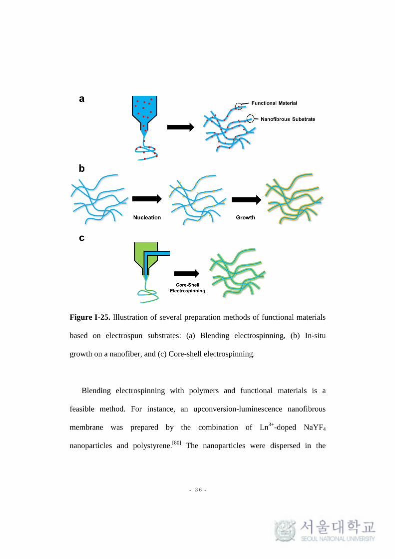
Figure I-25. Illustration of several preparation methods of functional materials
based on electrospun substrates: (a) Blending electrospinning, (b) In-situ
growth on a nanofiber, and (c) Core-shell electrospinning.
Blending electrospinning with polymers and functional materials is a
feasible method. For instance, an upconversion-luminescence nanofibrous
membrane was prepared by the combination of Ln3+
-doped NaYF4
nanoparticles and polystyrene.[80]
The nanoparticles were dispersed in the

- 37 -
polystyrene solution and successfully embedded into the transparent nanofibers.
The membrane showed high luminescent sensitivity and exhibited good
recyclability.
The in situ growth of functional materials on nanofiber substrates is another
method to prepare functional composites. In general, functionalized nanofibers
capable of interacting with desired materials are used as substrates. For example,
polyaniline was coated onto a flexible TiO2/SiO2 nanofiber membrane via in
situ post-polymerization.[81]
Polyaniline could act as a photosensitizer for TiO2
because the band gap of polyaniline is narrower than that of TiO2. Therefore,
this composite nanofiber showed good photocatalytic properties for organic dye
degradation under a visible light condition. Lee’s group prepared a crosslinked
poly(vinyl alcohol) nanofibrous membrane containing silver nanoparticles.[83]
The silver immobilized nanofibrous membrane demonstrated strong
antimicrobial activity.
The fabrication of core-shell nanofibers can be achieved using a coaxial
electrospinning method. During electrospinning, two different solutions pass
through two concentrically aligned spinnerets. Functional materials are
generally positioned in the shell while polymeric nanofiber cores act as the
substrate. Yang’s group reported core-shell type nanofiber-based gel polymer
electrolytes by coaxial electrospinning.[82]
Polymethylmethacrylate composed

- 38 -
the gelation shell, while polyacrylonitrile composed the rigid core nanofiber
substrate. These electrolytes showed enhanced ionic conductivity, stability, and
compatibility with a lithium-ion battery. A core-shell -structured
polyacrylonitrile-polybenzoxazine nanofiber membrane was fabricated.[83]
Because the electrospinning of polybenzoxazine itself is difficult due to its
crosslinked structure, coaxial electrospinning was performed using a
polyacrylonitrile solution (core) and a benzoxazine monomer solution (shell).
The as-prepared membranes were thermally treated at 300 oC for the
polymerization of benzoxazine. The core-shell porous membranes showed good
non-fouling properties owing to the low surface free energy of polybenzoxazine.
I-4-3. Electrospinning for 3D Nanofibrous Structures
Recently, 3D ultralight materials have attracted attention in tissue
engineering and energy applications.[79,84]
Generally, such materials have an
open cellular structure assembled by nanosized materials.[79]
Electrospun
nanofibers are good candidates for 3D ultralight materials due to their facile
fabrication process and high surface-to-volume ratios.[79,85]
However,
electrospun nanofibers are obtained as close-packed membranes, which

- 39 -
seriously restricts the possibility of the formation of 3D architectures.[79,85,86]
Various attempts have been made to achieve 3D nanofibrous structures.[86-88]
Nanofibrous aerogels have been prepared by the freeze-drying
method.[84,85,89]
Ding’s group reported nanofiber-based cellular aerogel.[85]
As
shown in Figure I-26, electrospun nanofibers were dispersed into a solution
containing a benzoxazine monomer and the nanofibrous cellular structure was
obtained by means of a freeze-drying process. The as-prepared aerogels were
thermally-treated for the formation of polybenzoxazine on the nanofiber surface,
giving the aerogels good mechanical stability. The nanofiber-based aerogels
had superelasticity and a very low density. Their morphology, size, and density
were tunable by controlling the experimental conditions. The aerogels had
potential applications in thermal insulation, sound adsorption, and oil-water
separation.

- 40 -
Figure I-26. Illustration of the preparation of nanofibrous aerogels by the
freeze-drying method.
I-5. References
1. Sing, K. S. W.; Everett, D. H.; Haul, R. A. W.; Moscou, L.; Pierotti, R.
A.; Rouquérol, J.; Siemieniewska, T. Pure Appl. Chem. 1985, 57,
603–619.

- 41 -
2. Dawson, R.; Cooper, A. I.; Adams, D. J. Prog. Polym. Sci. 2012, 37,
530-563.
3. Kim, S.; Lee, Y. M. Prog. Polym. Sci. 2015, 43, 1-32.
4. McKeown, N. B.; Budd, P. M. Macromolecules 2010, 43, 5163-5176.
5. Xu, Y.; Jin, S.; Xu, H.; Nagai, A.; Jiang, D. Chem. Soc. Rev. 2013, 42,
8012-8031.
6. Ravikovitch, P. I.; Vishnyakov, A.; Russo, R.; Neimark, A. V.
Langmuir 2000, 16, 2311-2320.
7. Bruanuer, S.; Emmett, P. H.; Teller, E. J. Am. Chem. Soc. 1938, 60,
309-319.
8. Walton, J. P. R. B.; Quirke, N. Mol. Simul. 1989, 2, 361-391.
9. Zhang, P.; Zhu, H.; Dai, S. ChemCatChem 2015, 7, 2788-2805.
10. Zhao, Y.; Liu, X.; Han, Y. RSC Adv. 2015, 5, 30310-30330.
11. Barakat, T.; Rooke, J. C.; Tidahy, H. L.; Hosseini, M.; Cousin, R.;
Lamonier, J. F.; Giraudon, J. M.; Weireld, G. D.; Su, B. L.; Siffert, S.
ChemSusChem 2011, 4, 1420-1430.
12. Dhakshinamoorthy, A.; Garcia, H. Chem. Soc. Rev. 2012, 41, 5262-
5284.
13. Liu, J.; Thallapally, P. K.; McGrail, B. P.; Brown, D. R.; Liu, J. Chem.
Soc. Rev. 2012, 41, 2308-2322.

- 42 -
14. Xu, S.; Luo, Y.; Tan, B. Macromol. Rapid Commun. 2013, 34, 471-484.
15. Ratvijitvech, T.; Dawson, R.; Laybourn, A.; Khimyak, Y. Z.; Adams, D.
J.; Cooper, A. I. Polymer 2014, 55, 321-325.
16. Jiang, J. X.; Su, F.; Trewin, A.; Wood, C. D.; Campbell, N. L.; Niu, H.;
Dickinson, C.; Ganin, A. Y.; Rosseinsky, M. J.; Khimyak, Y. Z.;
Cooper. A. I. Angew. Chem. Int. Ed. 2007, 46, 8574-8578.
17. Dawson, R.; Laybourn, A.; Khimyak, Y. Z.; Adams, D. J.; Cooper, A. I.
Macromolecules 2010, 43, 8524-8530.
18. Yuan, D.; Lu, W.; Zhao, D.; Zhou, H. C. Adv. Mater. 2011, 23, 3723-
3725.
19. Chen, L.; Honsho, Y.; Seki, S.; Jiang, D. J. Am. Chem. Soc. 2010, 132,
6742-6748.
20. Chen, Q.; Wang, J. X.; Yang, F.; Zhou, D.; Bian, N.; Zhang, X. J.; Yan,
C. G.; Han, B. H. J. Mater. Chem. 2011, 21, 13554-13560.
21. Chen, Q.; Luo, M.; Hammershøj, P.; Zhou, D.; Han, Y.; Laursen, B.
W.; Yan, C. G.; Han, B. H. J. Am. Chem. Soc. 2012, 134, 6084-6087.
22. Holst, J. R.; Stöckel, E.; Adams, D. J.; Cooper, A. I. Macromolecules
2010, 43, 8531-8538.
23. Li, B.; Gong, R.; Wang, W.; Huang, X.; Zhang, W.; Li, H.; Hu, C.; Tan,
B. Macromolecules 2011, 44, 2410-2414.

- 43 -
24. Wang, Z.; Zhang, B.; Yu, H.; Li, G.; Bao, Y. Soft Matter, 2011, 7,
5723-5730.
25. Li, G.; Wang, Z. Macromolecules 2013, 46, 3058-3066.
26. Pandey, P.; Katsoulidis, A. P.; Eryazici, I.; Wu, Y.; Kanatzidis, M. G.;
and Nguyen, S. Y. Chem. Mater. 2010, 22, 4974-4979.
27. Xu, C.; Hedin, N. J. Mater. Chem. A 2013, 1, 3406-3414.
28. Schwab, M G.; Fassbender, B.; Spiess, H. W.; Thomas, A.; Feng, X.;
Müllen, K. J. Am. Chem. Soc. 2009, 131, 7216-7217.
29. Rabbani, M. G.; El-Kaderi, H. M. Chem. Mater. 2011, 23, 1650-1653.
30. Katsoulidis, A. P.; He, J.; Kanatzidis, M. G. Chem. Mater. 2012, 24,
1937-1943.
31. Qian, H.; He, Q.; Zheng, J.; Li, S.; Zhang, S. Polymer 2014, 55, 550-
555.
32. Lee, H.; Kim, H.; Choi, T. J.; Park, H. W.; Chang, J. Y. Chem.
Commun. 2015, 51, 9805-9808.
33. Kim, H.; Choi, T. J.; Cha, M. C.; Chang, J. Y. J. Polym. Sci. Pol. Chem.
2013, 51, 3646-3653.
34. D’ Alessandro, D. M.; Smit, B.; Long, J. R. Angew. Chem. Int. Ed.
2010, 49, 6058-6082.
35. Bae, Y. S.; Snurr, R. Q. Angew. Chem. Int. Ed. 2011, 50, 11586-11596.

- 44 -
36. Cavenati, S.; Grande, C. A.; Rodrigues, A. E. J. Chem. Eng. Data 2004,
49, 1095-1101.
37. Chowdhury, P.; Bikkina, C.; Gumma, S. J. Phy. Chem. C 2009, 113,
6616-6621.
38. Torrisi, A.; Mellot-Draznieks, C.; Bell, R. G. J. Chem. Phys. 2010, 132,
044705.
39. Zhu, Y.; Long, H.; Zhang, W. Chem. Mater. 2013, 25, 1630-1635.
40. İslamoğlu, T.; Rabbani, M. G.; El-Kaderi. H. M. J. Mater. Chem. A
2013, 1, 10259-10266.
41. Fu, X.; Zhang, Y.; Gu, S.; Zhu, Y.; Yu, G.; Pan, C.; Wang, Z.; Hu. Y.
Chem. Eur. J. 2015, 21, 13357-13363.
42. Qian, X.; Zhu, Z. Q.; Sun, H. X.; Ren, F.; Mu, P.; Liang, W.; Chen, L.;
Li, A. ACS Appl. Mater. Interfaces 2016, 8, 21063-21069.
43. Yang, R. X.; Wang, T. T.; Deng, W. Q. Sci. Rep. 2015, 5, 10155.
44. Kou, Y.; Xu, Y.; Guo, Z.; Jiang, D. Angew. Chem. Int. Ed. 2011, 50,
8753-8757.
45. Xu, F.; Chen, X.; Tang, Z.; Wu, D.; Fu, R.; Jiang, D. Chem. Commun.
2014, 50, 4788-4790.
46. Li, Z.; Zhang, Y.; Xia, Y.; Liu, X. Chem. Commun. 2016, 52, 6613-
6616.

- 45 -
47. Cheng, T.; Zhao, Q.; Zhang, D.; Liu, G. Green Chem. 2015, 17, 2100-
2122.
48. Coperet, C.; Comas-Vives, A.; Conley, M. P.; Estes, D. P.; Fedorov,
A.; Mougel, V.; Nagae, H.; Nunez-Zarur, F.; Zhizhko, P. A. Chem.
Rev. 2016, 116, 323-421.
49. Song, C. E.; Lee, S. G. Chem. Rev. 2002, 102, 3495-3524.
50. Price, P. M.; Clark, J. H.; Macquarrie, D. J. J. Chem. Soc. Dalton Trans.
2000, 101-110.
51. Sun, Q.; Dai, Z.; Meng, X.; Xiao, F. S. Chem. Soc. Rev. 2015, 44,
6018-6034.
52. Davis, M. E.; Lobo, R. F. Chem. Mater. 1992, 4, 756-768.
53. Liu, D.; Guo, Q.; Hou, O.; Niwa, O.; You, T. ACS Catal. 2014, 4,
1825-1829.
54. Zhang, Y.; Riduan, S. N. Chem. Soc. Rev. 2012, 41, 2083-2094.
55. Chen, L.; Yang, Y.; Jiang, D. J. Am. Chem. Soc. 2010, 132, 9138-9143.
56. Wang, F.; Mielby, J.; Richter, F. H.; Wang, G.; Prieto, G.; Kasama, T.;
Weidenthaler, C.; Bongard, H. J.; Kegnæ s, S.; Fürstner, A.; Schüth, F.
Angew. Chem. Int. Ed. 2014, 53, 1-5.
57. Zhang, Y.; Zhang, Y.; Sun, Y. L.; Du, X.; Shi, J. Y.; Wang, W. D.;
Wang, W. Chem. Eur. J. 2012, 18, 6328-6334.

- 46 -
58. Lim, Y.; Cha, M. C.; Chang, J. Y. Sci. Rep. 2015, 5, 15957.
59. Liu, J.; Tobin, J. M.; Xu, Z.; Vilela, F. Polym. Chem. 2015, 6, 7251-
7255.
60. Tan, J.; Wan, J.; Guo, J.; Wang, C. Chem. Commun. 2015, 51, 17394-
17397.
61. Park, N.; Ko, K. C.; Shin, H. W.; Lee, S, M.; Kim, H. J.; Lee, J. Y.;
Son, S. U. J. Mater. Chem. A 2016, 4, 8010-8014.
62. Zhuang, X.; Gehrig, D.; Forler, N.; Liang, H.; Wagner, M.; Hansen, M.
R.; Laquai, F.; Zhang, F.; Feng, X. Adv. Mater. 2015, 27, 3789-3796.
63. Budd, P. M.; Elabas, E. S.; Ghanem, B. S.; Makhseed, S.; Mckeown, N.
B.; Msayib, K. J.; Tattershall, C. E.; Wang, D. Adv. Mater. 2004, 16,
456-459.
64. Zhang, C.; Li, P.; Cao, B. Ind. Eng. Chem. Res. 2015, 54, 8772-8781.
65. Gu, C.; Huang, N.; Gao, J.; Xu, F.; Xu, Y.; Jiang, D. Angew. Chem. Int.
Ed. 2014, 53, 4850-4855.
66. Zhang, L.; Wang, K.; Qian, X.; Liu, H.; Shi, Z. ACS Appl. Mater.
Interfaces 2013, 5, 2761-2766.
67. Becker, D.; Heidary, N.; Horch, M.; Gernert, U.; Zebger, I.; Schmidt,
J.; Fischer, A.; Thomas, A. Chem. Commun. 2015, 51, 4283-4286.

- 47 -
68. Yang, X.; Tan, L.; Xia, L.; Wood, C. D.; Tan, B. Macromol. Rapid
Commun. 2015, 36, 1553-1558.
69. Darder, M. d. M.; Salehinia, S,; Parra, J.; Herrero-Martinez, J.; Svec,
F.; Cerda, V.; Palomino, G. T.; Maya, F. ACS Appl. Mater. Interfaces
2017, 9, 1728-1736.
70. Svec, F.; Lv, Y. Anal. Chem. 2015, 87, 250-273.
71. Wu, K.; Guo, J.; Wang, C. Angew. Chem. Int. Ed. 2016, 55, 1-6.
72. Du, R.; Zhang, N.; Xu, H.; Mao, N.; Duan, W.; Wang, J.; Zhao, Q.; Liu,
Z.; Zhang, J. Adv. Mater. 2014, 26, 8053-8058.
73. Fan, W.; Liu, Z.; Zhang, Z.; Zhang, Q.; Ma, W.; Tan, D.; Li, A.
Micropor. Mesopor. Mater. 2014, 496, 335-340.
74. Destaye, A. G.; Lin, C. K.; Lee, C. K. ACS Appl. Mater. Interfaces
2013, 5, 4745-4752.
75. Zhao. R.; Wang, Y.; Li, X.; Sun, B.; Wang, C. ACS Appl. Mater.
Interfaces 2015, 7, 26649-26657.
76. Frenot. A.; Chronakis, I. S. Curr. Opin. Colloid Interface Sci. 2003, 8,
64-75.
77. Greiner, A.; Wendorff, J. H. Angew. Chem. Int. Ad. 2007, 46, 5670-
5703.
78. Teo, W. E.; Ramakrishna, S. Nanotechnology 2006, 17, 89-106.

- 48 -
79. Sun, B.; Long, Y. Z.; Zhang, H. D.; Li, M. M.; Duvail, J. L.; Jiang, X.
Y.; Yin, H. L. Prog. Polym. Sci. 2014, 39, 862-890.
80. Liu, K. C.; Zhang, Z. Y.; Shan, C. X.; Feng, Z. Q.; Li, J. S.; Song, C.
L.; Bao, Y. N.; Qi, X. H.; Dong, B.; Light Sci. Appl. 2016, 5, e16136.
81. Liu, Z.; Miao, Y. E.; Liu, M.; Ding, Q.; Tjiu, W. W.; Cui, X.; Liu, T. J.
Colloid Interf. Sci. 2014, 424, 49-55.
82. Bi, H.; Sui, G.; Yang, X. J. Power Sources 2014, 267, 309-315.
83. Kao, T. H.; Cheng, C. C.; Huang, C. F.; Chen, J. K. RSC Adv. 2015, 5,
58760-58771.
84. Duan, G.; Jiang, S.; Moss, T.; Agarwal, S.; Greiner, A. Polym. Chem.
2016, 7, 2759-2764.
85. Si, Y.; Yu, J.; Tang, X.; Ge, J.; Ding, B. Nat. Commun. 2014, 5, 5802.
86. Zhang, D.; Chang, J. Nano Lett. 2008, 8, 3283-3287.
87. Han, D.; Gouma, P. I. Nanomedicine. 2006, 2, 37-41.
88. Sun, B.; Long, Y. Z.; Yu, F.; Li, M. M.; Zhang, H. D.; Li, W. J.; Xu, T.
X. Nanoscale 2012, 4, 2134-2137.
89. Duan, G.; Jiang, S.; Jérôme, V.; Wendorff, J. H.; Fathi, A.; Uhm, J.;
Altstädt, V.; Herling, M.; Breu, J.; Freitag, R.; Agarwal, S.; Greiner, A.
Adv. Funct. Mater. 2015, 25, 2850-2856.

- 49 -
Chapter II.
Homogenized Electrospun Nanofiber Reinforced
Microporous Polymer Sponge
- 50 -
II-1. Introduction
High surface areas and narrow pore sizes are the characteristics of
microporous organic polymers (MOPs), allowing massive gas adsorptions and
selective molecular storage.[1-6]
MOPs are most outstanding in terms of
flexibility in the structural design of microporous materials including zeolites
and activated carbons. Many of MOPs have highly cross-linked conjugated
structures. They are synthesized by numerous chemical reactions including
metal-catalyzed cross-coupling reactions,[6-11]
Friedel-Craft reactions,[3,12]
Diels-
Alder reaction,[13]
thiol-yne reaction,[14]
and condensation reactions.[2,15,16]
In
addition, specific functional groups can be introduced to the MOPs by the
selection of appropriate comonomers or by post reactions.[17-19]
Based on these
synthetic advantages, MOPs have been tailored for specific applications such as
gas storage and separation,[2,20,21]
heterogeneous catalysis,[22,23]
light emitting
and harvesting,[5,6,24]
energy storage,[25-27]
sensors,[28]
and superabsorption.[29]
The mechanical property of a material is one of the major factors, which
determine its practical usage. Materials can have opportunities for broader
applications by combining particular physicochemical properties with
mechanical properties. There has been no extensive research focusing on the
mechanical properties of microporous polymers, as they are usually obtained as
powders with poor processability. Although there were some reports of

- 51 -
macroscopic gels formed during the polymerization of microporous polymers,
the gels fragmented into small particles in the work-up processes.[11,30]
The
growth of MOP on a substrate is a way to circumvent the processability
problem. A number of MOPs were polymerized on the surfaces of quartz,[31]
poly(methyl methacrylate),[32]
gold,[33]
copper,[34]
and graphene[35]
and were
obtained in various forms.
A sponge-like three-dimensional network structure has many attractive
properties such as reversible compressibility, high porosity, low density, and
flexibility. The combination of the MOPs and sponge-like network is
particularly useful for fast adsorption and release of chemicals. There are
several examples of MOP-based sponges for use in dye adsorption[36]
and
heterogeneous catalysis.[37]
Nevertheless, it is still a challenge to synthesize
MOP-based sponges with sufficient mechanical strength for practical
applications.
In this study, we prepared a compressible and monolithic MOP composite
sponge using a homogenized electrospun nanofiber as the reinforcement. The
MOP composite sponge was obtained by the Sonogashira-Hagihara coupling
reaction of an aryl halide and an alkyne in a dispersion of electrospun
nanofibers. Herein, we describe the synthesis, microporosity, and adsorption
properties of the composite sponge.

- 52 -
II-2. Experimental
Materials. Poly(vinyl alcohol) (PVA) (MW 85,000-124,000, 87-89 %
hydrolyzed), tetraethyl orthosilicate (TEOS) (> 99.0 %), 1,4-dibromobenzene
(98 %) and copper iodide (CuI) were purchased from Sigma-Aldrich. 2,5-
Dibromoaniline (97 %), N,N-diisopropylethylamine (DIPEA) (98+ %) and
methylene blue (MB) were obtained from ACROS Organics. 1,3,5-
Triethynylbenzene (> 98.0 %) and bis(triphenylphosphine)palladium(II)
dichloride (PdCl2(PPh3)2) (> 98.0 %) were purchased from Tokyo Chemical
Industry.
Electrospun PVA-Silica Nanofiber (PVASi) Mat. A PVA-silica nanofiber
mat was prepared according to the literature procedure with minor
modifications. A mixture of TEOS (1.09 g, 5.23 mmol), ethanol (1.09 g), H2O
(0.54 g) and HCl aqueous solution (0.1 mL, 2 M) were stirred at 60 oC for 1 h
and then was added to a solution of PVA (0.275 g) in deionized H2O (2 g).
After stirring at 60 oC for 1 h, the resultant solution was transferred into a
syringe equipped with an 18 gauge needle. The collecting plate covered with an
aluminium foil was placed 15 cm from the tip of the needle. Electrospinning
was performed at a voltage of 20 kV and a flow rate of 0.3 mL h-1
. The as-spun
nanofiber mat was heated at 80 oC for 24 h in the atmosphere to finish the sol-

- 53 -
gel reaction.
Dispersion of PVASi by Homogenization. A mat of PVASi pieces (2 g, 2
x 2 cm2) was homogenized in toluene (200 mL) at 13,000 rpm for 30 min using
a Homogenizer HG-15D (DAIHAN Scientific Co). The homogenization
process was repeated 3 times to give a homogeneous dispersion of PVASi.
Fabrication of MOP-Nanofiber Composite Monoliths (PVASi@TEDB-
NH2 and PVASi@TEDB). A dispersion of PVASi (6 mL) was mixed with
toluene (1 mL) and DIPEA (2 mL) into the 20 ml vial and degassed by the
nitrogen purging for 30 min. Subsequently, 1,3,5-triethynylbenzene (150 mg, 1
mmol) and 2,5-dibromoaniline (or 1,4-dibromobenzene, 1 mmol) were
dissolved to the dispersion. And then, PdCl2(PPh3)2 (20 mg, 24.7 μmol) and 6
mg of CuI (6 mg, 31.5 μmol) were added to the solution and sonicated for 5 s.
the prepared mixture was treated at 80 oC for 24 h without stirring under
aerobic condition. After reaction, a resultant composite was washed with
ethanol and THF and dried under vacuum for 24 h at room temperature.
Additionally, Soxhlet extraction was performed by methanol for 24 h. Finally,
the monolithic MOP-PVASi composite sponge was obtained.
For comparison, microporous polymer TEDB-NH2 and TEDB were

- 54 -
prepared in the same manner as described above except that a dispersion of
PVASi was not added to the reaction mixture.
MB Adsorption Properties of PVASi@TEDB-NH2. PVASi@TEDB-NH2
(100 mg) was immersed in an aqueous MB solution (20 mL, 0.05 mM) and was
manually compressed and released with a rate of 3 s for a cycle. The UV-Vis
absorption of the solution was measured every 40 cycles. For comparison, a
static adsorption experiment was carried out by immersing the same mass of
PVASi@TEDB-NH2 in the MB solution with stirring at 300 rpm and the UV-
Vis absorption of the solution was monitored. The sponge was reused after the
Soxhlet extraction with methanol and drying.
PVASi@TEDB-NH2 Based Syringe Filter. PVASi@TEDB-NH2 was
prepared to have a diameter of 19 mm and a height of 10 mm and was used as a
syringe filter. An aqueous MB solution (10 mL, 0.05 mM) was poured into a
syringe plugged with PVASi@TEDB-NH2 and filtered. The filtered solution
was observed by the UV-Vis absorption spectra.
Instrumental Characterization. Scanning electron microscopy (SEM)
images were obtained by a Carl Zeiss SUPRA 55VP. Transmission electron

- 55 -
microscopy (TEM) images were measured by a JEM-2100 operating at 200 kV.
TEM samples were dispersed in THF and a drop of the mixture was placed on a
carbon-coated copper TEM grid. Energy-dispersive X-ray spectroscopy (EDS)
elemental maps were obtained using an Oxford instrument X-MaxN detector
and analyzed with an AZtecEnergy EDS analyser. Solid-state 13
C NMR spectra
were recorded on a Bruker Avance 400WB spectrometer (100 MHz) equipped
with a CP-MAS probe. Powder X-ray diffraction (PXRD) patterns were
measured using a New D8 Advance (Cu Kα radiation, λ = 1.54 Å).
Thermogravimetric analyses (TGA) were performed on a TA modulated
TGA2050 with a heating rate of 10 °C/min under nitrogen. The FT-IR spectra
were measured by a PERKIN ELMER Spectrum GX I spectrometer using KBr
pellets. The compression tests were performed by an Instron 5543 universal
testing machine. A cylindrical sponge having a diameter of 21 mm and height
of 17 mm was used for the measurement. The strain-stress curves were recorded
at a strain rate of 5 mm min-1
. 10 cycles of the loading-unloading test was
measured at a strain rate of 50 mm min-1
. N2 adsorption-desorption isotherms
and CO2 uptake properties were investigated by a Belsorp-Max (BEL Japan,
Inc.) apparatus. UV-Vis spectra were obtained with a Sinco S-3150
spectrometer.

- 56 -
II-3. Results and Discussion
II-3-1. Synthesis and the Morphology of the MOP-Nanofiber Composites
Scheme II-1. Synthesis of PVASi@TEDB-NH2 and PVASi@TEDB.
Our synthetic approach to the MOP-electrospun nanofiber composite
sponge is shown in Scheme II-1. The Sonogashira-Hagihara coupling reaction
is a mild and efficient method to form a conjugated structure and has been
considerably used to synthesize a microporous polymer.[7,8,10,11]
1,4-
Dibromobenzene and 2,5-dibromoaniline were chosen as the aryl halides and
1,3,5-triethynylbenzene as the aryl acetylene monomer for the synthesis of the

- 57 -
MOPs with highly crosslinked structures. The Sonogashira–Hagihara coupling
reaction between these monomers has been reported to yield microporous
polymers in a powder form.[38,39]
In this study, two polymers, TEDB and
TEDB-NH2, were also obtained as powders from the reaction of 1,3,5-
triethynylbenzene with 1,4-dibromobenzene and 2,5-dibromoaniline,
respectively (Figure II-1a, b). TEDB and TEDB-NH2 showed a BET surface
area of 718 and 548 m2g
-1, respectively (Figure II-1c, d).
Figure II-1. SEM images of (a) TEDB and (b) TEDB-NH2. N2 adsorption-
desorption isotherms measured at 77 K for (c) TEDB and (d) TEDB-NH2.

- 58 -
The MOP growth on the electrospun fiber was attempted by carrying out the
Sonogashira-Hagihara coupling reaction of 1,4-dibromobenzene or 2,5-
dibromoaniline with 1,3,5-triethynyl-benzene in the presence of homogenized
PVASi nanofibers prepared from a solution of PVA and TEOS. PVASi showed
good chemical and thermal stability, because of the crosslinked structure
resulting from the reaction between the hydroxyl groups of PVA and
TEOS.[40,41]
PVASi was obtained as a nonwoven mat. The SEM and TEM
images showed that PVASi had a smooth surface and an average fiber diameter
of 230 nm (Figure II-2). In order to secure sufficient area for the MOP growth,
the PVASi mat was cut into pieces, and they were homogenized in toluene until
a stable dispersion was formed (Figure II-3a, b). The homogenized PVASi
nanofibers had a length ranging from dozens to hundreds of micrometers
(Figure II-3c).

- 59 -
Figure II-2. SEM images of PVASi (a) before and (b) after homogenization.
(c) TEM image and (d) the diameter distribution of as-spun PVASi.
Figure II-3. Photographs of (a) pieces of a PVASi mat in toluene and (b) a
dispersion of homogenized PVASi in toluene. (c) SEM image of individual
homogenized PVASi nanofibers at low magnification.

- 60 -
Both PVASi@TEDB-NH2 and PVASi@TEDB obtained from 2,5-
dibromoaniline and 1,4-dibromobenzene, respectively, appeared to have
monolithic sponge-like structures. However, their microstructures were very
different. Figure II-4 shows the SEM and TEM images of PVASi@TEDB-NH2.
The SEM image of the composite prepared from 2,5-dibromoaniline
(PVASi@TEDB-NH2) showed entangled nanofibers and each nanofiber was
uniformly wrapped with a thick layer of the polymer. An average layer
thickness was 325 nm. The EDS analysis confirmed that nitrogen atoms from
TEDB-NH2 were uniformly dispersed on the surface of the nanofibers (Figure
II-5). In contrast, the composite obtained from 1,4-bromobenzene
(PVASi@TEDB) had a very thin polymer layer with an irregular surface. A
considerable amount of the polymer powders was also found between the fibers
(Figure II-6). This result could be attributed to the hydrophobic property of the
polymer. TEDB consisted of hydrocarbon units and poorly interacted with the
hydrophilic surface of PVASi.

- 61 -
Figure II-4. (a), (b) SEM and (c), (d) TEM images of PVASi@TEDB-NH2. (e)
The diameter distribution of PVASi@TEDB-NH2 nanofibers.
Figure II-5. (a) EDS elemental analysis and (b) mapping of nitrogen for
PVASi@TEDB-NH2.

- 62 -
Figure II-6. (a) SEM and (b) TEM images of PVASi@TEDB.
Two factors affected the growth of the MOP on the electrospun fiber
surface. The first one was the adsorption property of metallic catalysts on the
nanofiber surface. PVASi had many hydroxyl groups on the surface that could
interact with various metal ions.[42,43]
Therefore, palladium (II) and copper (I)
catalysts for the Sonogashira-Hagihara coupling reaction could be bound to the
surface of PVASi to initiate the polymerization.[34]
The second one was the
interaction between the polymer and the nanofiber surface. TEDB-NH2
obtained from 2,5-dibromoaniline had primary amino groups, which could form
hydrogen bonds with the hydroxyl groups on the surface of PVASi.[44]
As
observed in the TEM images, PVASi@TEDB-NH2 had a core-shell structure
(Figure II-4c, d). TEDB-NH2 coated the nanofibers and also acted as a material
to weld the nanofibers, ensuring the construction of highly interconnected
geometry as well as high structural stability.[45,46]
The fused and entangled fiber

- 63 -
structure and a large void space conferred reversible elasticity to the composite
under compressive force.[47]
The average density of PVASi@TEDB-NH2 was
30.4 mg cm-3
, which was comparable to those of silica aerogels[48]
and carbon
nanotube foams.[49]
II-3-2. Characterization of PVASi@TEDB-NH2
As-prepared PVASi@TEDB-NH2 exhibited reversible compressibility
(Figure II-7). The compressive stress-strain curves of PVASi@TEDB-NH2
measured at the set strain maxima of 20, 40 and 60% showed reversible stress-
strain hysteresis (Figure II-7b) as observed in the open-cell foams.[47,50]
During
10 loading-unloading cycles to a maximum strain of 40%, only a small change
was observed in the stress-strain curves (Figure II-7c), indicating that the
composite had a high mechanical strength against compression.[47,51]

- 64 -
Figure II-7. (a) Images of PVASi@TEDB-NH2 under loaded and unloaded
conditions (strain = 40%). (b) Compressive stress-strain curves (maximum
stress = 20, 40 and 60%) and (c) 10 cycles of loading-unloading test results of
PVASi@TEDB-NH2 (maximum strain = 40%).
The structures of TEDB-NH2 and PVASi@TEDB-NH2 were further
characterized by solid state 13
C NMR and FT-IR spectroscopy (Figure II-8a, b).
In the 13
C NMR spectrum, PVASi@TEDB-NH2 showed the peaks for aromatic
and acetylenic carbons of TEDB-NH2 at 149, 132, 124, 110 and 90 ppm[39,52]

- 65 -
and the peaks at 66, 45 and 21 ppm corresponding to the carbons of PVA
containing the unhydrolyzed acetate side groups.[53]
In the FT-IR spectrum of
PVASi@TEDB-NH2, the peaks for -C≡C- groups of TEDB-NH2 and Si-O-Si
bonds of PVASi appeared at 2222 and 1075 cm-1
, respectively. The PXRD
patterns of PVASi@TEDB-NH2 and TEDB-NH2 did not show any distinct
peaks, suggesting that they had amorphous structures (Figure II-8c).
PVASi@TEDB-NH2 was thermally stable up to 300 oC when measured by
TGA (Figure II-8d). The char yields of PVASi, TEDB-NH2 and
PVASi@TEDB-NH2 at 800 oC were 55.5, 79.4 and 73.2 wt%, respectively. We
calculated the content of PVASi (Y) in PVASi@TEDB-NH2 to be 25.9 wt%
using the following equation:
C1 x (Y/100) + C2 x {(100-Y)/100} = C3 (1)
where C1, C2, C3 are the char yields of PVASi, TEDB-NH2 and
PVASi@TEDB-NH2, respectively.

- 66 -
Figure II-8. (a) Solid state 13
C CP/MAS NMR spectra, (b) FT-IR spectra, and
(c) PXRD patterns of TEDB-NH2 and PVASi@TEDB-NH2. (d) TGA
thermograms of PVASi, TEDB-NH2, and PVASi@TEDB-NH2.
II-3-3. Porosity of PVASi@TEDB-NH2
The porosities of PVASi@TEDB-NH2 and TEDB-NH2 were investigated
by cryogenic N2 adsorption-desorption analysis (Figure II-9a). Both materials

- 67 -
showed a combination of type I and IV isotherms,[54]
indicating the existence of
micropores and mesopores inside the materials. The average BET surface areas
of PVASi@TEDB-NH2 and TEDB-NH2 for three time measurements were 447
and 506 m2g
-1, respectively. The surface area of PVASi@TEDB-NH2 was
slightly lower than TEDB-NH2 because of the presence of PVASi nanofibers
which didn’t have microporosity. The N2 adsorption-desorption isotherms of
PVASi@TEDB-NH2 and TEDB-NH2 showed similar patterns, indicating that
the pore structure of TEDB-NH2 was not significantly changed by the PVASi
substrate from which the polymer was grown. The non-local density functional
theory (NLDFT) pore size distributions (Figure II-9b) showed that both
PVASi@TEDB-NH2 and TEDB-NH2 had the micropores and the mesopores.
The CO2 uptake amounts of PVASi@TEDB-NH2 and TEDB-NH2 measured at
273 K and 1 bar were 1.45 and 1.95 mmol g-1
, respectively (Figure II-10). The
CO2 uptake property of TEDB-NH2 was similar to the result reported in the
literature.[39]

- 68 -
Figure II-9. (a) N2 adsorption-desorption isotherms measured at 77 K and (b)
NLDFT pore size distributions of PVASi@TEDB-NH2 and TEDB-NH2.
Figure II-10. CO2 uptakes at 273 K of PVASi@TEDB-NH2 and TEDB-NH2.
II-3-4. Application of PVASi@TEDB-NH2 as Organic Dye Adsorbent

- 69 -
Because of smaller pore sizes compared to those of mesoporous and
macroporous materials,[55]
microporous materials have a great potential as the
adsorbents of toxic small molecules dissolved in water such as aromatic
compounds,[56]
organic dyes,[13,57]
and endocrine disruptors.[58]
The adsorption
properties of PVASi@TEDB-NH2 in an aqueous solution were investigated
using MB as the model pollutant.
PVASi@TEDB-NH2 was immersed in an aqueous MB solution and
manually compressed and released in situ at a rate of ~3 s per cycle. Figure II-
11 shows the UV-Vis spectra of the MB solution (0.05 mM). After 360
compression-release cycles, the absorbance of the solution reached zero,
indicating the complete removal of MB as we could observe with naked eye
(Figure II-12a). When the composite was allowed to absorb MB without the
compression and release, a very small amount of the dye was removed in the
same period time. Relatively more MB was adsorbed by PVASi@TEDB-NH2
with stirring, but its removal rate was still far lower than that of the
compression and release method. This result clearly stated the advantage of the
compressible microporous material as an adsorbent. When PVASi@TEDB-
NH2 was compressed in the MB solution, inner pores were closely packed and
deformed[47]
and the air inside the composite sponge escaped. When the
pressure was released, the composite sponge returned to the initial volume and

- 70 -
absorbed the solution. Through this process, more MB molecules could be
transferred to and entered in the micropores of PVASi@TEDB-NH2 by the
capillary force.[59]
Since the mass transportation in the micropores is relatively
inhibited rather than the mesopores and the macropores, dye molecules were
efficiently captured and confined inside the micropores. In addition, hydrophilic
amine groups within the frame could help TEDB-NH2 to have the affinity with
water.[55,60]
Figure II-13 shows the water absorption property of the composite
sponge. PVASi@TEDB-NH2 was floating on water at the beginning. After 10
cycles of compression and release, however, the composite sponge was
immersed in water. Although the surface of PVASi@TEDB-NH2 was
hydrophobic, the compression and release process allowed the rapid absorption
of water. The dye adsorbed PVASi@TEDB-NH2 was simply regenerated by the
Soxhlet extraction with methanol and could be reused. MB adsorption
efficiency of the sponge was maintained even after the 5-time cyclic adsorption
test (Figure II-12b).

- 71 -
Figure II-11. UV–vis spectra of the aqueous MB solution (initial concentration
= 5 x 10⁻⁵
M) measured after removing the dye by (a) compression and release
process and by static adsorption (b) without stirring and (c) with stirring.

- 72 -
Figure II-12. (a) Photographs of aqueous MB solutions before (left) and after
(right) adsorption. (b) Recycle test results of PVASi@TEDB-NH2 for MB
adsorption by the compression and release process.
Figure II-13. Photographs of PVASi@TEDB-NH2 in water (a) before and (b)
after 10 cycles of compression and release.

- 73 -
A syringe filtration is another fast and efficient method of separation.[61,62]
PVASi@TEDB-NH2 can be used as a syringe filter because of its monolithic
property, compressibility and hierarchical porosity. PVASi@TEDB-NH2 was
prepared that fitted into a syringe and used for filtration. The blue MB solution
turned colorless after filtration (Figure II-14a), and the UV-Vis spectrum of the
filtrate proved that MB molecules were completely removed (Figure II-14b). A
syringe filter was recycled through the Soxhlet extraction and reused five times
without significant deterioration in the adsorption property (Figure II-15).
Figure II-14. (a) Sequential photographs of the filtration process using a
PVASi@TEDB-NH2 syringe filter. (b) UV–vis spectra of the aqueous MB
solution before and after the filtration.

- 74 -
Figure II-15. UV-Vis spectrum of the aqueous MB solution measured after
filtration with a five times regenerated syringe filter.
II-4. Conclusions
In summary, a compressible MOP-nanofiber composite, PVASi@TEDB-
NH2, was fabricated via the Sonogashira-Hagihara coupling reaction of 2,5-
dibromoaniline and 1,3,5-triethynylben-zene in a dispersion of homogenized
PVASi nanofibers. The microstructure analyses revealed that PVASi@TEDB-
NH2 had a core-shell structure, in which TEDB-NH2 uniformly coated the
PVASi nanofibers. The PVASi nanofibers were interconnected by entanglement,
and the junctions were bonded with the polymer, providing the composite with
structural stability and compressibility. The composite was compressed and

- 75 -
released repeatedly, allowing the rapid removal of a pollutant in water. It was
anticipated that the synthetic method of MOPs using electrospun nanofibers as
the substrates would open a new way to fabricate monolithic and structurally
stable functional microporous polymer composites.
II-5. References
1. Yuan, S.; Dorney, B.; White, D.; Kirklin, S.; Zapol, P.; Yu, L.; Liu, D. J.
Chem. Commun. 2010, 46, 4547–4549.
2. Xu, C.; Hedin, N. J. Mater. Chem. A 2013, 1, 3406-3414.
3. Xiang, L.; Zhu, Y.; Gu, S.; Chen, D.; Fu, X.; Zhang, Y.; Yu, G.; Pan, C.;
Hu, Y. A. Macromol. Rapid Commun. 2015, 36, 1566–1571.
4. Pandey, P.; Katsoulidis, A.P.; Eryazici, I.; Wu, Y.; Kanatzidis, M.G.;
Nguyen, S. T. Chem. Mater. 2010, 22, 4974–4979.
5. Jiang, J. X.; Trewin, A.; Adams, D. J.; Cooper, A. I. Chem. Sci. 2011, 2,
1777–1781.
6. Chen, L.; Honsho, Y.; Seki, S.; Jiang, D. J. Am. Chem. Soc. 2010, 132,
6742–6748.
7. Fischer, S.; Schimanowitz, A.; Dawson, R.; Senkovska, I.; Kaskel, S.;
Thomas, A. J. Mater. Chem. A 2014, 2, 11825–11829.

- 76 -
8. Lim, H.; Chang, J. Y. Macromolecules 2010, 43, 6943–6945.
9. Schmidt, J.; Werner, M.; Thomas, A. Macromolecules 2009, 42, 4426–
4429.
10. Jiang, J. X.; Su, F.; Trewin, A.; Wood, C.D.; Niu, H.; Jones, J. T. A.;
Khimyak, Y. Z.; Cooper, A. I. J. Am. Chem. Soc. 2008, 130, 7710–
7720.
11. Jiang, J.X.; Su, F.; Trewin, A.; Wood, C.D.; Campbell, N. L.; Niu, H.;
Dickinson, C.; Ganin, A. Y.; Rosseinsky, M. J.; Khimyak, Y. Z.;
Cooper, A. I. Angew. Chemie. Int. Ed. 2007, 46, 8574–8578.
12. Lim, H.; Cha, M. C.; Chang, J. Y. Polym. Chem. 2012, 3, 868–870.
13. Kim, H.; Choi, T.; Cha, M. C.; Chang, J. Y. J. Polym. Sci. Part A
Polym. Chem. 2013, 51, 3646–3653.
14. Lee, H.; Kim, H.; Choi, T. J.; Park, H. W.; Chang, J. Y. Chem.
Commun. 2015, 51, 9805–9808.
15. Li, G.; Zhang, B.; Yan, J.; Wang, Z. J. Mater. Chem. A 2014, 2,
18881–18888.
16. Nandi, S.; Werner-Zwanziger, U.; Vaidhyanathan, R. J. Mater. Chem.
A 2015, 3, 21116–21122.
17. Xu, Y.; Jin, S.; Xu, H.; Nagai, A.; Jiang, D. Chem. Soc. Rev. 2013, 42,
8012–8031.

- 77 -
18. Dawson, R.; Cooper, A. I.; Adams, D. J. Prog. Polym. Sci. 2012, 37,
530–563.
19. Cooper, A.I. Adv. Mater. 2009, 21, 1291–1295.
20. Chen, Y.; Sun, H.; Yang, R.; Wang, T.; Pei, C.; Xiang, Z.; Zhu, Z.;
Liang, W.; Li, A.; Deng, W. J. Mater. Chem. A 2015, 3, 87-91.
21. Bao, L.; Sun, H.; Zhu, Z.; Liang, W.; Mu, P.; Zang, J.; Li, A. Mater.
Lett. 2016, 178, 5-9.
22. Ma, B.C.; Ghasimi, S.; Landfester, K.; Vilela, F.; Zhang, K. A. I. J.
Mater. Chem. A 2015, 3, 16064–16071.
23. Zhang, Y.; Riduan, S. N. Chem. Soc. Rev. 2012, 41, 2083–2094.
24. Xu, Y.; Nagai, A.; Jiang, D. Chem. Commun. 2013, 49, 1591–1593.
25. Kou, Y.; Xu, Y.; Guo, Z.; Jiang, D. Angew. Chemie. Int. Ed. 2011, 50,
8753–8757.
26. Xu, F.; Chen, X.; Tang, Z.; Wu, D.; Fu, R.; Jiang, D. Chem. Commun.,
2014, 50, 4788–4790.
27. Vilela, F.; Zhang, K.; Antonietti, M. Energy Environ. Sci. 2012, 5,
7819-7832.
28. Gu, C.; Huang, N.; Gao, J.; Xu, F.; Xu, Y.; Jiang, D. Angew. Chemie.
Int. Ed. 2014, 53, 4850–4855.
29. Du, R.; Zhang, N.; Xu, H.; Mao, N.; Duan, W.; Wang, J.; Zhao, Q.;

- 78 -
Liu, Z.; Zhang, J. Adv. Mater. 2014, 26, 8053–8056.
30. Jiang, J. X.; Su, F.; Niu, H.; Wood, C. D.; Campbell, N. L.; Khimyak,
Y. Z; Cooper, A. I. Chem. Commun. 2008, 4, 486–488.
31. Cha, M. C.; Lim, Y.; Chang, J. Y. J. Polym. Sci. Part A Polym. Chem.
2015, 53, 2336–2342.
32. Tan, J.; Wan, J.; Guo, J.; Wang, C. Chem. Commun. 2015, 51, 17394–
17397.
33. Becker, D.; Heidary, N.; Horch, M.; Gernert, U.; Zebger, I.; Schmidt,
J.; Fischer, A.; Thomas, A. Chem. Commun. 2015, 51, 4283–4286.
34. Zhang, L.; Wang, K.; Qian, X.; Liu, H.; Shi, Z. ACS Appl. Mater.
Interfaces 2013, 5, 2761–2766.
35. Zhuang, X.; Gehrig, D.; Forler, N.; Liang, H.; Wagner, M.; Hansen, M.
R; Laquai, F.; Zhang, F.; Feng, X. Adv. Mater. 2015, 27, 3789–3796.
36. Lim, Y.; Cha, M. C.; Chang, J. Y. Sci. Rep. 2015, 5, 15957.
37. Wu, K.; Guo, J.; Wang, C. Angew. Chem. Int. Ed. 2016, 55, 1-6.
38. Kiskan, B.; Weber, J. ACS Macro Lett. 2012, 1, 37–40.
39. Ratvijitvech, T.; Dawson, R.; Laybourn, A.; Khimyak, Y. Z.; Adams,
D. J.; Cooper, A. I. Polymer 2014, 55, 321–325.
40. Pirzada, T.; Arvidson, S. A.; Saquing, C. D.; Shah, S. S.; Khan, S. A.
Langmuir 2012, 28, 5834–5844.

- 79 -
41. Keshtkar, A. R.; Irani, M.; Moosavian, M .A. J. Radioanal. Nucl.
Chem. 2013, 295, 563–571.
42. Wang, J.; Kondrat, S. A.; Wang, Y.; Brett, G. L.; Giles, C.; Bartley, J.
K.; Lu, L.; Liu, Q.; Kiely, C. J.; Hutchings, G. J. ACS Catal. 2015, 5,
3575–3587.
43. Haider, S.; Park, S. Y. J. Memb. Sci. 2009, 328, 90–96.
44. Liu, Z.; Miao, Y. E.; Liu, M.; Ding, Q.; Tjiu, W. W.; Cui, X.; Liu, T. J.
Colloid Interface Sci. 2014, 424, 49–55.
45. Lin, Z.; Gui, X.; Gan, Q.; Chen, W.; Cheng, X.; Liu, M.; Zhu, Y.;
Yang, Y.; Cao, A.; Tang, Z. Sci. Rep. 2015, 5, 11336.
46. Kim, K. H.; Oh, Y.; Islam, M. F. Nat. Nanotechnol. 2012, 7, 562–566.
47. Si, Y.; Yu, J.; Tang, X.; Ge, J.; Ding, B. Nat. Commun. 2014, 5, 5802.
48. Pierre, A. C.; Pajonk, G. M. Chem. Rev. 2002, 102, 4243–4266.
49. Worsley, M. A.; Kucheyev, S. O.; Satcher, J. H.; Hamza, A. V.;
Baumann, T. F. Appl. Phys. Lett. 2009, 94, 2007–2010.
50. Lorna, J. G.; Michael, F. A. Cellular Solids: Structure and Properties,
2nd ed; Cambridge University Press, 1997.
51. Ruan, C.; Ai, K.; Li, X.; Lu, L. Angew. Chemie. Int. Ed. 2014, 53,
5556–5560.
52. Dawson, R.; Laybourn, A.; Khimyak, Y. Z.; Adams, D. J.; Cooper, A. I.

- 80 -
Macromolecules 2010, 43, 8524–8530.
53. Terao, T.; Maeda, S; Saika, A. Macromolecules 1983, 16, 1535–1538.
54. Sing, K. S. W.; Everett, D. H.; Haul, R .A. W.; Moscou, L.; Pierotti, R.
A.; Rouquérol, J.; Siemieniewska, T. Pure Appl. Chem. 1985, 57, 603-
619.
55. Li, B.; Su, F.; Luo, H.; Liang, L.; Tan, B. Microporous Mesoporous
Mater. 2011, 138, 207–214.
56. Ji, L.; Liu, F.; Xu, Z.; Zheng, S.; Zhu, D. Environ. Sci. Technol. 2009,
43, 7870–7876.
57. Yang, R. X.; Wang, T. T.; Deng, W .Q. Sci. Rep. 2015, 5, 10155.
58. Zhao, R. S.; Wang, X.; Yuan, J. P.; Zhang, L. L. Microchim. Acta 2009,
165, 443–447.
59. Zhuang, X.; Wan, Y.; Feng, C.; Shen, Y.; Zhao, D. Chem. Mater. 2009,
21, 706-716.
60. Lάszlό, K. Microporous Mesoporous Mater. 2005, 80, 205–211.
61. Fu, G.; Su, Z.; Jiang, X.; Yin, J. Polym. Chem. 2014, 5, 2027–2034.
62. Lu, Y.; He, W.; Cao, T.; Guo, H.; Zhang, Y.; Li, Q.; Shao, Z.; Cui, Y.;
Zhang, X. Sci. Rep. 2014, 4, 5792.

- 81 -
Chapter III.
Preparation of a Microporous Polymer Membrane
Containing Pd Nanoparticles as a Catalytic Membrane

- 82 -
III-1. Introduction
Catalytic membranes are a class of heterogeneous catalysts, which have
catalytic sites inside porous membrane supports. They can perform a catalytic
reaction during diverse membrane processes, which have many advantages
compared with other heterogeneous catalysts.[1]
For instance, catalytic
membranes are suitable for continuous catalytic processes, which can give
steady conversion over time.[1-3]
Also, they don’t need to be removed from the
reaction mixture after a reaction, which facilitates a reuse of catalysts.[3,4]
Catalytic membranes have been used for various applications such as gas-phase
reactions,[5-7]
photocatalytic reactions[2,8,9]
and liquid-phase reactions.[3,4,10]
Catalytic membranes have been prepared using various organic and inorganic
materials. Especially, polymeric materials for catalytic membranes have
attracted a considerable interest because of some advantages such as low costs,
good processability, and large scale preparation.[4,11,12]
Friedel-Crafts reaction between aromatic compounds is an efficient way to
synthesize hypercrosslinked microporous polymers (HCPs).[13]
Relatively cheap
catalysts are used for Friedel-Crafts reaction. Various types of aromatic
compounds are available for the reaction, which enables to produce diverse
functional HCPs.[13-17]
Several groups have studied HCP-based heterogeneous
catalysts containing metal ions,[14,18]
metal nanoparticles,[17,19,20]
and

- 83 -
organocatalysts.[15,18]
However, HCPs are general prepared in insoluble powder
forms, which limits severely their applications for catalytic membranes.
Recently, a HCP-based catalytic membrane was prepared by the in-situ Friedel-
Crafts reaction of a polystyrene-ionic liquid membrane,[21]
but studies on this
topic are still sparse.
In this work, we prepared a HCP-based microporous catalytic membrane
using an electrospun nanofiber membrane as a substrate. Electrospinning is a
powerful method to make a membrane composed of nanofibers, showing a
large surface area, high porosity, and reliable mechanical stability.[22,23]
Moreover, an electrospun nanofiber membrane can be functionalized with
various materials such as polymers, metal oxides, and metal-organic
frameworks.[24-26]
The HCP-based microporous membrane was obtained by
carrying out the Friedel-Crafts reaction of an aromatic monomer in the presence
of an aminated polyacrylonitrile (APAN) membrane. Palladium (Pd)
nanoparticles were incorporated into the APAN membrane and used for a
catalytic reduction of 4-nitrophenol (4-NP).

- 84 -
III-2. Experimental
Materials. 1,1’-Bi-2-naphthol (99 %), palladium chloride (PdCl2) (59 wt%
Pd) and diethylenetriamine were purchased from ACROS Organics.
Dimethoxymethane (98 %), and sodium borohydride (NaBH4) (95 %) were
obtained from Tokyo Chemical Industry. Polyacrylonitrile (PAN) (MW ~
150,000) and 4-nitrophenol (4-NP) (99 %) were purchased from Sigma-Aldrich.
Iron (III) chloride anhydrous (FeCl3) was purchased from Fisher chemicals.
Sodium carbonate (Na2CO3) was obtained from Shinyo pure chemicals Co.
Other solvents were purchased from Junsei Chemical. All materials were used
without any purification.
Preparation of the Aminated PAN (APAN) Nanofibrous Membrane.
PAN (0.6 g) was dissolved in DMF (5.4 g) at 50 oC. The PAN solution was
transferred into a syringe with an 18 gauge needle. The syringe was placed 20
cm from the collecting plate covered with an aluminum foil. Electrospinning
was performed at a voltage of 20 kV and a flow rate of 1.0 mL h-1
. The as-spun
PAN nanofiber membrane was dried at 60 oC for 24 h.
The APAN nanofibrous membrane was prepared by an amination of the
PAN membrane using diethylenetriamine. It was performed via the previously
reported method.[27]

- 85 -
Preparation of the HCP-Nanofiber Composite Membrane (APAN-
HCP). FeCl3 (2594 mg, 1.6 * 10-2
mol) was dispersed in 40 mL of 1,2-
dichloroethane. The APAN membrane (300 mg) and 1,1’-bi-2-naphthol (1145
mg, 4 * 10-3
mol) were added to the solution, which was stirred for 24 h at room
temperature. Subsequently, dimethoxymethane (1219 mg, 1.6 * 10-2
mol) was
added dropwise to the mixture. The mixture was heated to 80 oC with stirring at
400 rpm for 24 h. The as-prepared composite membrane was washed with THF
and methanol and dried under vacuum at room temperature.
The Palladium Decorated HCP-Nanofiber Composite Membrane
(APAN-HCP-Pd). PdCl2 (140 mg) was dissolved in 70 mL of acetonitrile at 90
oC. APAN-HCP (350 mg) was immersed in the PdCl2 solution at 90
oC with
stirring at 300 rpm. After 24 h, the membrane was removed from the PdCl2
solution and immersed in 100 mL of NaBH4 solution (0.25 M of NaBH4, H2O :
EtOH = 1 : 3) for 3 h. The resultant membrane was washed with H2O and EtOH
and dried under vacuum at room temperature.
Catalytic Reduction of 4-Nitrophenol by the Membrane Catalyst via the
Filtration. 100 mL of a 4-nitrophenolate aqueous solution was prepared by
mixing 50 mL of 4-NP solution (2 * 10-4
M) and 50 mL of NaBH4 (8 * 10-2
M)

- 86 -
solution. APAN-HCP-Pd membrane having a circular shape with a diameter of
55 mm (0.72 mm thickness, 350 mg) was placed in a Buchner funnel with a
filter paper as the support. The 4-nitrophenolate solution was passed through
APAN-HCP-Pd by the vacuum pump and the filtrate was collected in a round-
bottom flask. The filtration was ended within 3 minutes. The filtrate underwent
the same process for the fifth time. UV-Vis spectroscopy was used to monitor
the reduction of 4-NP.
Instrumental Characterization. The FT-IR spectrum was measured by a
TENSOR27 FT-IR Spectrometer. Solid-state 13
C NMR spectrum was recorded
on a Bruker Avance II spectrometer (125 MHz). Powder X-ray diffraction
(PXRD) patterns were observed using a New D8 Advance (Cu Kα radiation, λ =
1.54 Å ). Thermogravimetric analyses (TGA) were performed on a TA
modulated TGA2050 with a heating rate of 10 °C/min under nitrogen. Scanning
electron microscopy (SEM) images were obtained by a Carl Zeiss SUPRA
55VP. Energy-dispersive X-ray spectroscopy (EDS) elemental map was
obtained using an Oxford instrument X-MaxN detector and analyzed with an
AZtecEnergy EDS analyzer. N2 adsorption-desorption isotherms were
investigated by a Belsorp-Max (BEL Japan, Inc.) apparatus. The tensile tests
were performed by an Instron-5543 universal testing machine. Transmission
electron microscopy (TEM) images were obtained using a Talos L120C

- 87 -
operating at 120 kV. TEM samples were prepared by dropping a dispersion of
materials in EtOH on a carbon-coated copper TEM grid. X-ray photoelectron
spectroscopy (XPS) was measured by a KRATOA AXIS-His spectrometer
equipped with an Mg Ka X-ray source. Inductively coupled plasma mass
spectrometry (ICP-MS) was measured by a Varian 820-MS to calculate a
weight percentage of Pd in the membrane. Pd was dissolved in strong nitric acid
before measurement. UV-Vis spectra were recorded with a Sinco S-3150
spectrometer.

- 88 -
III-3. Results and Discussion
III-3-1. Synthesis and Characterizations of a HCP-based Microporous
Membrane
Our synthetic strategy to a HCP-based microporous membrane is shown in
Scheme III-1. Friedel-Crafts reaction of an aromatic compound with
dimethoxymethane has been reported to produce a microporous polymer.[28]
We
chose 1,1’-bi-2-naphthol as an aromatic monomer for the preparation of a HCP,
which can chelate metal ions such as Mo, Pd, and Pt ions.[29]
Polyacrylonitrile (PAN) has been widely used for the production of
nanofibrous membranes because of its low cost, thermal stability, chemical
resistance, and mechanical stability.[30,31]
Moreover, PAN nanofibers are easily
functionalized by the reactions of cyano groups to be suitable for certain
applications such as ion-exchange and metal ion adsorption.[31-34]
In this study,
an aminated polyacrylonitrile (APAN) nanofibrous membrane was chosen as a
substrate because of its outstanding adsorption properties of metal ions
including Fe(III).[33,34]
In the Friedel-Crafts reaction with FeCl3 as a catalyst,
Fe(III) ions were expected to be bound to APAN nanofibers and to act as
reaction sites for the polymerization.[35,36]
Also, the aromatic monomer, 1,1’-bi-
2-naphthol, could interact with amine groups of APAN nanofibers through

- 89 -
hydrogen bonding. The APAN nanofiberous membrane was prepared by the
amination reaction of a electrospun PAN membrane with diethylenetriamine
according to the previously reported method.[27]
Scheme III-1. Schematic illustration of preparation of the HCP-based
microporous membrane.
The amination of the PAN membrane was characterized by FT-IR
spectroscopy. As shown in Figure III-1, PAN shows a strong peak at 2244 cm-1
corresponding to the stretching vibration of nitrile groups. After amination, the
intensity of nitrile peak decreased while new peaks at 1655 cm-1
and 1587 cm-1
appeared, which corresponded to the bending vibration of the N-H group and
the stretching vibration of the amide groups.[27,33]

- 90 -
Figure III-1. FT-IR spectra of PAN and APAN.
Figure III-2 shows the microstructures of the PAN and the APAN
membranes. The PAN membrane was composed of networked nanofibers
having a diameter around 300 nm. The APAN membrane had the same
microstructure as the PAN membrane, indicating that the amination reaction
didn’t change the membrane structure.

- 91 -
Figure III-2. SEM images of (a) the PAN membrane and (b) the APAN
membrane.
A HCP coated nanofibrous membrane (APAN-HCP) was fabricated by
carrying out the Friedel-Crafts reaction of 1,1’-bi-2-naphthol with
dimethoxymethane in the presence of the APAN membrane. The photographs
of the membranes are shown in Figure III-3. The APAN membrane had
yellowish color while the PAN membrane had white color. After the Friedel-
Crafts reaction, the color of the membrane turned to brown, implying the
incorporation of the HCP. The shapes of the membranes were not changed by
the reactions.

- 92 -
Figure III-3. The photographs of the PAN membrane, the APAN membrane,
and APAN-HCP.
Figure III-4 shows the SEM images of APAN-HCP and the HCP. APAN-
HCP had a nanofibrous structure having a diameter around 400 nm while the
HCP was composed of nanoparticles and nanofibers. The nanofibers of APAN-
HCP were smoothly coated by the HCP.[35]

- 93 -
Figure III-4. SEM images of (a), (b) APAN-HCP and (c), (d) the HCP.
The chemical structures of APAN-HCP and the HCP were characterized by
FT-IR and solid 13
C NMR spectroscopy (Figure III-5a, b). In the FT-IR
spectrum, APAN-HCP showed all the peaks of APAN and the HCP. The 13
C
NMR spectrum of the HCP showed two distinct peaks at 152 ppm and 127 ppm,
which corresponded to C-OH carbons and other aromatic carbons, respectively.
A broad peak at 30 ppm was assigned to aliphatic bridges between aromatic
rings.[15]
APAN-HCP also showed the peaks of the HCP but the peak intensity
at 30 ppm was much larger than that observed in the HCP due to the presence
of the aliphatic carbons in the nanofibers.

- 94 -
The PXRD patterns of APAN-HCP and the HCP are shown in Figure III-5c.
The HCP did not have any distinct peaks, indicating its amorphous structure.
APAN-HCP showed the peaks at 2θ = 17o and 29
o, which were assigned to the
(100) and (101) planes of PAN.[37]
The TGA thermogram in Figure III-5d showed that APAN-HCP was
thermally stable up to 300 oC. The char yields of the HCP, APAN, and APAN-
HCP at 800 oC were 64.1, 39.0, and 55.4 wt%, respectively. The weight
percentage of the HCP in APAN-HCP was 65.1 wt%, when based on the TGA
results.[35]

- 95 -
Figure III-5. (a) FT-IR spectra of APAN, APAN-HCP, and the HCP. (b) Solid
state 13
C CP/MAS NMR spectra and (c) PXRD patterns of the HCP and APAN-
HCP. (d) TGA thermograms of APAN, APAN-HCP and the HCP.
The porosities of APAN, the HCP, and APAN-HCP were investigated by
N2 adsorption-desorption analysis at 77 K (Figure III-6a). The HCP and APAN-
HCP showed similar type I isotherms, which indicated the presence of
micropores.[38]
The surface areas of APAN, the HCP, and APAN-HCP were 19,
620, and 375 m2g
-1, respectively. As shown in Figure III-6b, the HCP and

- 96 -
APAN-HCP had similar non-local density functional theory (NLDFT) pore size
distribution patterns, suggesting that the pore structure of the HCP was not
significantly influenced by the reaction conditions.[35]
Figure III-6. (a) N2 adsorption-desorption isotherms of APAN, the HCP, and
APAN-HCP. (b) NLDFT pore size distributions of the HCP and APAN-HCP.
To investigate the effect of amine groups on the HCP growth at the
nanofiber surface, a HCP-based microporous membrane (PAN-HCP) was
prepared using the PAN membrane as a substrate instead of the APAN
membrane. Compared with APAN-HCP, PAN-HCP had a very thin layer of the
HCP on the surface of the nanofiber (Figure III-7a). The BET surface area of
PAN-HCP was 108 m2g
-1, which was much lower than that of APAN-HCP
(Figure III-7b). These results suggested that the introduction of amino groups

- 97 -
onto the nanofibers significantly contributed to the even growth of the HCP on
the nanofiber surface through their favorable interactions with the catalyst and
the monomer.[35]
Figure III-7. (a) SEM image of PAN-HCP. (b) Comparison of N2 adsorption-
desorption isotherms of APAN-HCP and PAN-HCP.
APAN-HCP maintained the mechanical strength and flexibility of the
APAN membrane (Figure III-8a). The mechanical properties of the APAN
membrane and APAN-HCP were measured by the tensile tests (Figure III-8b, c).
The ultimate tensile strength of APAN-HCP was slightly higher than that of the
APAN membrane, while the ultimate strain of APAN-HCP was lower than that
of the APAN membrane. This result indicated the stiffening of the membrane,
probably due to the formation of the interfiber bonding caused by the growth of
the HCP.[39-41]
APAN-HCP could be easily cut into a desired shape using a

- 98 -
knife or a scissor.
Figure III-8. (a) Photograph of the bent APAN-HCP. Tensile stress-strain
curves of (b) the APAN membrane and (c) APAN-HCP.
III-3-2. Fabrication of a Pd-Containing Microporous Catalytic Membrane
and Its Catalytic Ability
The microporous catalytic membrane was prepared via in-situ growth of Pd
nanoparticles inside APAN-HCP (APAN-HCP-Pd). Briefly, PdCl2 was first
adsorbed to APAN-HCP. Pd2+
ion could be immobilized by 1,1’-bi-2-naphthol

- 99 -
units of the HCP.[29]
The reduction of Pd2+
ions was performed by immersing
the membrane in an aqueous NaBH4 solution. As shown in the SEM images,
the fibrous structure of the membrane was not significantly changed after the
reduction reaction (Figure III-9a). The TEM analysis of APAN-HCP-Pd clearly
showed the formation of Pd nanoparticles (Figure III-9b). The EDS elemental
mapping indicated that Pd species were homogeneously distributed on the
nanofibers (Figure III-9c). In the XPS analysis of APAN-HCP-Pd, two peaks
appeared at 336.1 and 341.4 eV, corresponding to Pd 3d5/2 and Pd 3d3/2 binding
energies of Pd(0) (Figure III-9d).[42]
The amount of Pd species in the catalytic
membrane was 6.90 wt%, when calculated by ICP-MS analysis.

- 100 -
Figure III-9. (a) SEM image and (b) TEM image of APAN-HCP-Pd. (c) EDS
mapping of Pd for APAN-HCP-Pd. (d) High-resolution XPS spectrum of Pd3d
region of APAN-HCP-Pd.
The catalytic ability of APAN-HCP-Pd was evaluated in the reduction of 4-
NP. APAN-HCP-Pd having a circular shape with a diameter of 55 mm was
placed in the Buchner funnel with a filter paper as the support. And the 4-
nitrophenolate aqueous solution (1 * 10-4
M, 100 mL) was passed under
vacuum through APAN-HCP-Pd. The calculated flow rate of the solution was

- 101 -
0.56 mL sec-1
. Since APAN-HCP-Pd had a hierarchical pore structure, the
solution was rapidly passed through APAN-HCP-Pd.[43,44]
Figure III-10a shows the UV absorption spectra of the 4-nitrophenolate
solution measured after the several repeated catalytic reactions with APAN-
HCP-Pd. The absorption peak of the 4-nitrophenolate solution at 400 nm
significantly decreased after it was passed through the membrane while the
peak at 298 nm increased, indicating the reduction of 4-NP to 4-
aminophenol.[43,45]
The conversion yields were 68.0 and 95.1 % when two and
six cycles of the reaction were performed, respectively. APAN-HCP-Pd
maintained its original structure and flexibility during many cycles of the
reaction. The catalytic activity of APAN-HCP-Pd was slightly decreased after
two sets of six cycles of the reaction as shown in Figure III-10b.

- 102 -
Figure III-10. (a) UV-Vis spectra of the aqueous 4-nitrophenolate solution
(initial concentration = 1 x 10⁻⁴
M) measured during the filtration process with
APAN-HCP-Pd. (b) Change in the 4-NP conversion efficiency of APAN-HCP-
Pd during recycling (1 set = six filtration cycles).
III-4. Conclusions
In summary, a microporous catalytic membrane, APAN-HCP-Pd, was
fabricated using an electrospun APAN membrane as a substrate. Friedel-Crafts
reaction of 1,1’-bi-2-naphthol with dimethoxymethane in the presence of the
APAN membrane produced a hierarchically porous membrane, where the
APAN nanofibers were uniformly coated with the microporous HCP. The HCP-
based nanofibrous membrane had microporosity, mechanical stability, and
flexibility. Pd nanoparticles were successfully immobilized inside the HCP-

- 103 -
based membrane by the in-situ reduction of Pd2+
ions. APAN-HCP-Pd showed a
good catalytic ability in the reduction of 4-NP as a membrane catalyst. APAN-
HCP-Pd had a potential use for flow-through catalytic membrane reactions.
III-5. References
1. Westermann, T.; Melin, T. Chem. Eng. Process. 2009, 48, 17-28.
2. Iglesias, O; Rivero, M. J.; Urtiaga, A. M.; Ortiz, I. Chem. Eng. J. 2016,
305, 136-148.
3. Gu, Y.; Favier, I.; Pradel, C.; Gin, D. L.; Lahitte, J-. F.; Noble, R. D.;
Gómez, M.; Remigy, J-. C. J. Membrane Sci. 2015, 492, 331-339.
4. Wang, Z.; Chen, X.; Li, K.; Bi, S.; Wu, C.; Chen, L. J. Membrane Sci.
2015, 496, 95-107.
5. Armor, J. N. J. Membrane Sci. 1998, 147, 217-233.
6. Meng, L.; Tsuru, T. Catal. Today 2016, 268, 3-11.
7. Kim, S. -J.; Tan, S.; Claure, M. T.; Gil, L. B.; More, K. L.; Liu, Y.;
Moore, J. S.; Dixit, R. S.; Pendergast, Jr. J. G.;, Sholl, D. S.; Jones, C.
W.; Nair, S. ACS Appl. Mater. Interfaces 2016, 8, 24671-24681.
8. Athanasekou, C. P.; Moustakas, N. G.; Morales-Torres, S.; Pastrana-
Martínez, L. M.; Figueiredo, J. L.; Faria, J. L.; Silva, A. M. T.; Dona-

- 104 -
Rodriguez, J. M.; Romanos, G. E.; Falaras, P. Appl. Catal. B-Environ.
2015, 178, 12-19.
9. Zhou, K. -G.; McManus, D.; Prestat, E.; Zhong, X.; Shin, Y.; Zhang, H.
-L.; Haigh, S. J.; Casiraghi, C. J. Mater. Chem. A 2016, 4, 11666-11671.
10. Moschetta, E. G.; Negretti, S.; Chepiga, K. M.; Brunelli, N. A.;
Labreche, Y.; Feng, Y.; Rezaei, F.; Lively, R. P.; Koros, W. J.; Davies, H.
M. L; Jones, C. W. Angew. Chem. Int. Ed. 2015, 54, 6470-6474.
11. Ozdemir, S. S.; Buonomenna, M. G.; Drioli, E. Appl. Catal. A-Gen.
2006, 307, 167-183.
12. Mendes, A.; Sousa, J. M. Catal. Today 2003, 82, 241-254.
13. Xu, S.; Luo, Y.; Tan, B. Macromol. Rapid Commun. 2013, 34, 471-484.
14. Li, B.; Guan, Z.; Wang, W.; Yang, X.; Hu, J.; Tan, B.; Li, T. Adv. Mater.
2012, 24, 3390-3395.
15. Wang, J.; Sng, W.; Yi, G.; Zhang, Y. Chem. Commun. 2015, 51, 12076-
12079.
16. Zhang, A.; Gao, H.; Li, W.; Bai, H.; Wu, S.; Zeng, Y.; Cui, W.; Zhou,
X.; Li, L. Polymer 2016, 101, 388-394.
17. Li, H.; Meng, B.; Chai, S-. H.; Liu, H.; Dai, S. Chem. Sci., 2016, 7,
905-909.
18. Dou, Z.; Xu, L.; Zhi, Y.; Zhang, Y.; Xia, H.; Mu, Y.; Liu, X. Chem. Eur.

- 105 -
J. 2016, 22, 9919-9922.
19. Mondal, J.; Kundu, S. K.; Ng, W. K. H.; Singuru, R.; Borah, P.; Hirao,
H.; Zhao, Y.; Bhaumik, A. Chem. Eur. J. 2015, 21, 19016-19027.
20. Puthiaraj, P.; Ahn, W. -S. Catal. Sci. Technol. 2016, 6, 1701-1709
21. Chinnappan, A.; Chung, W. -J.; Kim, H. J. Mater. Chem. A 2015, 3,
22960-22968.
22. Greiner, A.; Wendorff, J. H. Angew. Chem. Int. Ed. 2007, 46, 5670-
5703.
23. Thavasi, V.; Singh, G.; Ramakrishna, S. Energy Environ. Sci. 2008, 1,
205-221.
24. Yan, J.; Huang, Y.; Miao, Y. -E.; Tjiu, W. W.; Liu, T. J. Hazard. Mater.
2015, 283, 730-739.
25. Wu, J.; Yang, H. ACS Catal. 2014, 4, 144-151.
26. Zhang, Y.; Yuan, S.; Feng, X.; Li, H.; Zhou, J.; Wang, B. J. Am. Chem.
Soc. 2016, 138, 5785-5788.
27. Zhang, J.; Xue, Q.; Pan, X.; Jin, Y.; Lu, W.; Ding, D.; Guo, Q. Chem.
Eng. J. 2017, 307, 643-649.
28. Dawson, R.; Stevens, L. A.; Drage, T. C.; Snape, C. E.; Smith, M. W.;
Adams, D. J.; Cooper, A. I. J. Am. Chem. Soc. 2012, 134, 10741-10744.
29. Griffith, W. P.; Nogueira, H. I. S.; White, A. J. P.; Williams, D. J.

- 106 -
Polyhedron 1997, 16, 1323-1329.
30. Neghlani, P. K.; Rafizadeh, M.; Taromi, F. A. J. Hazard. Mater. 2011,
186, 182-189.
31. Liu, Q.; Zhong, L. -B.; Zhao, Q. -B.; Frear, C.; Zheng, Y. -M. ACS Appl.
Mater. Interfaces 2015, 7, 14573-14583.
32. Zhang, B. W.; Fischer, K.; Bieniek, D.; Kettrup, A. React. Polym. 1994,
24, 49-58.
33. Deng, S.; Bai, R.; Chen, J. P. Langmuir 2003, 19, 5058-5064.
34. Kiani G. R.; Sheikhloie, H.; Arsalani, N. Desalination 2011, 269, 266-
270.
35. Kim, J. G.; Choi, T. J.; Chang, J. Y. Chem. Eng. J. 2016, 306, 242-250.
36. Zhang, L.; Wang, K.; Qian, X.; Liu, H.; Shi. Z. ACS Appl. Mater.
Interfaces 2013, 5, 2761-2766.
37. Zhao, W.; Lu, Y.; Jiang, J.; Hu. L.; Zhou, L. RSC Adv. 2015, 5, 23508-
23518.
38. Sing, K.S.W.; Everett, D.H.; Haul, R.A.W.; Moscou, L.; Pierotti, R.A.;
Rouquérol, J.; Siemieniewska, T. Pure Appl. Chem. 1985, 57, 603-619.
39. Choi, S. -S. J. Mater. Sci. 2004, 39, 1511-1513.
40. Destaye, A. G.; Lin, C. -K.; Lee, C. -K. ACS Appl. Mater. Interfaces
2013, 5, 4745-4752.

- 107 -
41. Si, Y.; Yu, J.; Tang, X.; Ge, J.; Ding, B. Nat. Commun. 2014, 5, 5802.
42. Qian, H.; He, Q.; Zheng, J.; Li, S.; Zhang, S. Polymer 2014, 55, 550-
555.
43. Wang, R.; Liu, Y.; Li, B.; Hsiao, B. S.; Chu, B. J. Membrane Sci. 2012,
392-393, 167-174.
44. Raza, A.; Ding, B.; Zainab, G.; El-Newehy, M.; Al-Deyab, S. S.; Yu, J.
J. Mater. Chem. A 2014, 2, 10137-10145.
45. Niu, T.; Xu, J.; Xiao, W.; Huang, J. RSC Adv., 2014, 4, 4901-4904.

- 108 -
Chapter IV.
Preparation of a Sulfur-Functionalized Microporous
Polymer Sponge and In Situ Growth of Silver
Nanoparticles: a Compressible Monolithic Catalyst

- 109 -
IV-1. Introduction
Porous materials with high surface areas are widely used for heterogeneous
catalysis as supports. The main advantages of a heterogeneous catalyst over its
homogeneous analogue are the easy separation of the catalyst from a reaction
mixture and its tolerance in harsh operating conditions. The chemical and
morphological structures of the supporting materials have a significant
influence on the performance of the heterogeneous catalysts through their
interactions with catalytically active species.[1]
Typical catalyst supports are
porous materials, including a variety of carbon materials and oxides such as
alumina and silica. Organic polymers with low surface areas have been used in
catalytic reactions, where reagents or catalysts are immobilized to the polymer
backbones.[2]
Recent advances on microporous organic polymers (MOPs) provide new
opportunities to develop efficient heterogeneous catalysts. MOPs have
characteristics of high surface areas, low density and flexibility in the
architectural design.[3,4]
As heterogeneous catalyst supports, MOPs have the
following significant advantage over porous carbon and oxide materials: MOPs
are easily functionalized by the post-modifications and thereby the interactions
between the active species and the supports can be adjusted,[4-6]
resulting in
high catalytic activity and recyclability.

- 110 -
A majority of MOPs are constructed by coupling reactions of
multifunctional monomers.[5-12]
They have highly cross-linked structures and
usually obtained as infusible powders, which seriously restricts their
processability and use.[13]
Several methods have been studied to fabricate shape
controlled MOPs like spherical nanoparticles[14]
and films.[11.15,16]
Recently we
reported sponge-like monolithic microporous polymers.[17]
Spongy polymeric
materials have useful properties, such as low density, high porosity and
compressibility.[17-19]
These attractive features would allow easy uptake and
release of chemicals.
Herein, we report a monolithic catalyst based on a MOP sponge. The MOP
sponge had a three-dimensional network structure composed of tubular polymer
fibers. It showed reversible compressibility and hierarchical porosity. The
sponge was functionalized with sulfur groups and then decorated with silver
nanoparticles. The activity of the monolithic catalyst was evaluated in the
reduction reaction of 4-nitrophenol. The acceleration of the reaction rate was
achieved by taking advantage of the compressible property of the catalyst.

- 111 -
IV-2. Experimental
Materials. 1,4-Diiodotetrafluorobenzene (98 %), copper iodide (CuI), silver
nitrate (99 %) and 4-nitrophenol (4-NP) (99 %) were purchased from Sigma-
Aldrich. 1,3,5-Triethynylbenzene (98 %),
bis(triphenylphosphine)palladium(II) dichloride (Pd(PPh3)2Cl2) (98 %), 1,3-
propanedithiol (99 %) and sodium borohydride (NaBH4) (95 %) were
purchased from Tokyo Chemical Industry. Azobisisobutyronitrile (AIBN) was
obtained from Junsei Chemical. AIBN was recrystallized by methanol, and
other chemicals were used without further purification.
Preparation of a Microporous Polymer Sponge. 1,3,5-Triethynylbenzene
(225 mg, 1.5 mmol) and 1,4-diiodotetrafluorobenzene (603 mg, 1.5 mmol) were
dissolved in a cosolvent of toluene (9.0 mL) and triethylamine (4.5 mL).
Pd(PPh3)2Cl2 (30.0 mg, 37.0 μmol) and CuI (9.0 mg, 47.2 μmol) were added to
the solution and dispersed by sonication. The mixture was moved to the 10 mL
vial and heated at 60 oC for 24 h without stirring under aerobic conditions. A
resultant polymer was washed with THF and ethanol and was Soxhlet extracted
using methanol. After drying in vacuo at room temperature, the MOP sponge
was obtained as a monolith.

- 112 -
Sulfur-Functionalized MOP Sponge (S-MOPS). A piece of MOP sponge
(100 mg) was immersed in 25 mL of toluene and degassed by bubbling with
nitrogen. 1,3-Propanedithiol (218 mg, 2.0 mmol) and AIBN (330 mg, 2.0
mmol) were added to the mixture. After stirring for 1 h at room temperature, the
thiol-yne reaction was performed at 90 oC for 24 h under nitrogen. The resulting
functionalized polymer was washed with THF and ethanol and dried in vacuo at
room temperature.
Silver Decorated MOP Sponge as a Heterogeneous Catalyst (S-MOPS-
Ag). Silver nitrate (140 mg, 0.82 mmol) was dissolved in a mixture of H2O (15
mL) and ethanol (30 mL). S-MOPS (140 mg) was put in the solution and was
compressed and released 100 times to uptake Ag+ ions. The sponge was
removed from the silver nitrate solution and squeezed to get rid of the excess
solution. The Ag+ ion containing-sponge was immediately immersed in a
solution of NaBH4 (308 mg, 8.24 mmol) in a mixture of H2O (15 mL) and
ethanol (30 mL). The sponge was compressed and released 100 times and
stirred for 3 h. The MOP sponge-Ag composite was washed with H2O and
ethanol and dried in vacuo at room temperature.
Catalytic Reduction Reaction of 4-Nitrophenol by S-MOPS-Ag. A piece

- 113 -
of S-MOPS-Ag (60.0 mg) was immersed in ethanol for 1 min and was squeezed
to remove ethanol. The ethanol wetted-sponge was then immersed in H2O. After
stirring for 10 min, the sponge was squeezed to remove H2O. A reaction
solution was prepared by mixing aqueous solutions of 4-NP (0.2 mM, 15 mL)
and NaBH4 (80.0 mM, 15 mL). Subsequently, the S-MOPS-Ag was added to
the solution, and manually compressed and released with a rate of 3 s for the
cycle. The reduction of 4-NP was monitored by UV-Vis absorption
spectroscopy. For comparison, the reduction experiments without stirring (static
condition) and with stirring were also carried out under the same conditions
except that the sponge was not compressed. The sponge was reused after
washing with H2O and ethanol and drying.
Instrumental Characterization. Scanning electron microscopy (SEM)
images were observed by a Carl Zeiss SUPRA 55VP. Transmission electron
microscopy (TEM) images were obtained using a JEM-2100 operating at 200
kV. TEM samples were prepared by dropping a dispersion of the polymers in
THF on a carbon-coated copper TEM grid. Energy-dispersive X-ray
spectroscopy (EDS) elemental maps were measured by an Oxford instrument
X-MaxN detector and analysed with an AZtecEnergy EDS analyzer. Solid-state
13C NMR spectra were obtained on a Bruker Avance 400WB spectrometer (100

- 114 -
MHz) equipped with a CP-MAS probe. Elemental analyses were performed on
a Flash EA 1112 elemental analyzer. Powder X-ray diffraction (PXRD) patterns
were recorded using a New D8 Advance (Cu Kα radiation, λ = 1.54 Å).
Thermogravimetric analyses (TGA) were performed using a TA modulated
TGA2050 with a heating rate of 10 °C/min under nitrogen. FT-IR spectra were
observed by a PERKIN ELMER Spectrum GX I spectrometer using KBr pellets.
The compression tests were performed by an Instron 5543 universal testing
machine. A cylindrical sponge having a diameter of 18 mm and height of 13
mm was used for the measurement. The strain-stress curves were recorded at a
strain rate of 3 mm min-1. A 10 cycles of the loading-unloading test was carried
out at a strain rate of 30 mm min-1
. N2 adsorption-desorption isotherms were
obtained by a Belsorp-Max (BEL Japan, Inc.) apparatus. Inductively coupled
plasma mass spectrometry (ICP-MS) was performed using a Varian 820-MS to
calculate a weight percentage of Ag in the composite. Ag nanoparticles were
dissolved in strong nitric acid before measurement. X-ray photoelectron
spectroscopy (XPS) was measured by a KRATOA AXIS-His spectrometer
equipped with a Mg Kα X-ray source. UV-Vis spectra were recorded with a
Sinco S-3150 spectrometer.

- 115 -
IV-3. Results and Discussion
IV-3-1. Synthesis and Characterization of a MOP Sponge
A monolithic MOP sponge was synthesized via Sonogashira-Hagihara
coupling reaction between 1,4-diiodotetrafluorobenzene and 1,3,5-
triethynylbenzene (Scheme IV-1). The reaction was performed at 60 oC without
stirring in a co-solvent of toluene and TEA (2:1, v/v). The reaction mixture
turned into a viscose gel in 60 min, and a monolithic MOP was isolated after 24
h. The MOP could be prepared in various shapes and sizes using a reaction
vessel as a mold. For example, a cylindrical MOP was synthesized in a 10 mL
vial as shown in Scheme IV-1. The MOP was light with an average density of
47.0 mg cm-3
and maintained its original shape even after washing and drying.
The 13
C solid state NMR spectrum showed all the carbon peaks from the
expected polymer structure. The peaks from aromatic carbons appeared at 143,
132, 120 and 102 ppm, and the carbon peaks from acetylene groups showed up
at 98 and 77 ppm (Figure IV-1).

- 116 -
Scheme IV-1. Reaction scheme for the synthesis of the MOP sponge and its
photo image.
Figure IV-1. Solid state 13
C CP/MAS NMR spectrum of the MOP sponge.
Figure IV-2 shows compressive stress-strain test results for the MOP sponge
at the set strain maxima of 20 and 40 %. The MOP sponge had reversibly
compressible properties. The stress-strain curve patterns were similar to those
of porous foam-like materials, which consisted of the elastic region (ε < 15 %)

- 117 -
and the plateau region (15 % < ε < 40 %).[20]
After 10 loading-unloading cycles
to a maximum strain of 40%, a slight decrease in the maximum stress was
observed, but the deformation was recoverable upon release of the stress.
Figure IV-2. (a) Images of the MOP sponge under compression and release
conditions. (b) Compressive stress-strain curves (maximum strain = 20 and
40 %) and (c) 10 cycles of loading-unloading test results of the MOP sponge
(maximum strain = 40 %).
The microscopy study revealed that the monolithic and compressible
properties of the MOP sponge resulted from its intriguing fibrous

- 118 -
microstructure (Figure IV-3). Polymer fibers with a diameter of hundreds of
nanometers were found to constitute the monolith. The TEM and SEM images
showed that each polymer fiber had a hollow tubular structure with open ends.
The overall morphology of the MOP sponge resembled that of a carbon
nanotube (CNT) sponge.[20,21]
Fibrous tubular structures are usually not
expected for cross-linked polymers prepared from multifunctional monomers.
We presume that tubular shapes were induced by step reactions in combination
with the structured self-assembly of the reactants in the Sonogashira-Hagihara
coupling reaction,[22]
but need further study to fully understand the mechanism.
A few other examples of polymerization systems that produce tubular fibers
have been reported.[22-24]
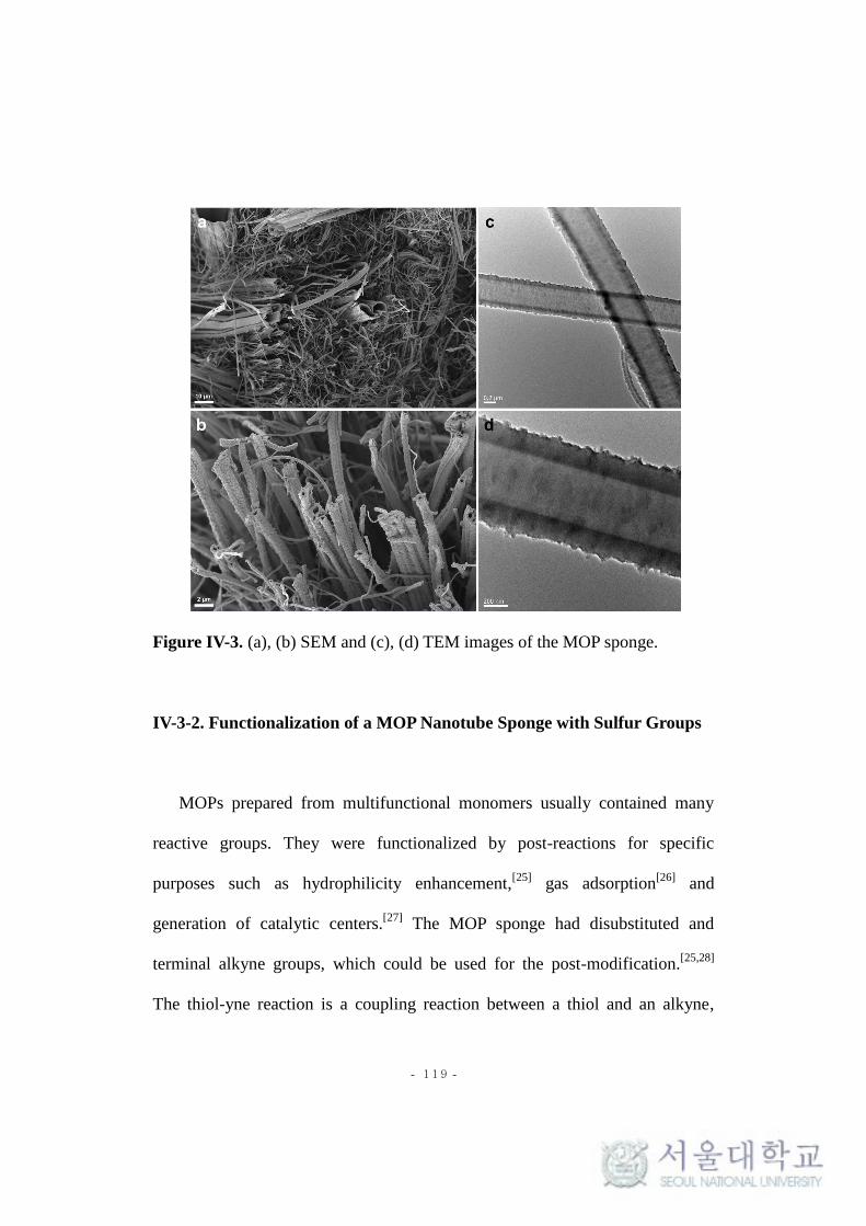
- 119 -
Figure IV-3. (a), (b) SEM and (c), (d) TEM images of the MOP sponge.
IV-3-2. Functionalization of a MOP Nanotube Sponge with Sulfur Groups
MOPs prepared from multifunctional monomers usually contained many
reactive groups. They were functionalized by post-reactions for specific
purposes such as hydrophilicity enhancement,[25]
gas adsorption[26]
and
generation of catalytic centers.[27]
The MOP sponge had disubstituted and
terminal alkyne groups, which could be used for the post-modification.[25,28]
The thiol-yne reaction is a coupling reaction between a thiol and an alkyne,

- 120 -
which proceeds in a high yield via a radical mechanism. The thiol-yne reaction
of the MOP sponge was carried out with 1,3-propanedithiol using AIBN as a
radical initiator to give a sulfur-functionalized MOP sponge (S-MOPS)
(Scheme IV-2). Sulfur groups are well known for their high affinity to heavy
metals such as silver, gold and palladium.[29,30]
Scheme IV-2. Thiol-yne modification of the MOP sponge and a possible
structure of S-MOPS.
S-MOPS maintained the monolithic shape and the entangled fibrous tubular
microstructure as observed in the SEM and TEM images (Figure IV-4a, b). The
EDS elemental mapping showed the homogeneous distribution of sulfur atoms
on the surface of the polymer (Figure IV-4c). S-MOPS showed reversible
compressibility similar to the MOP sponge (Figure IV-5), but the maximum
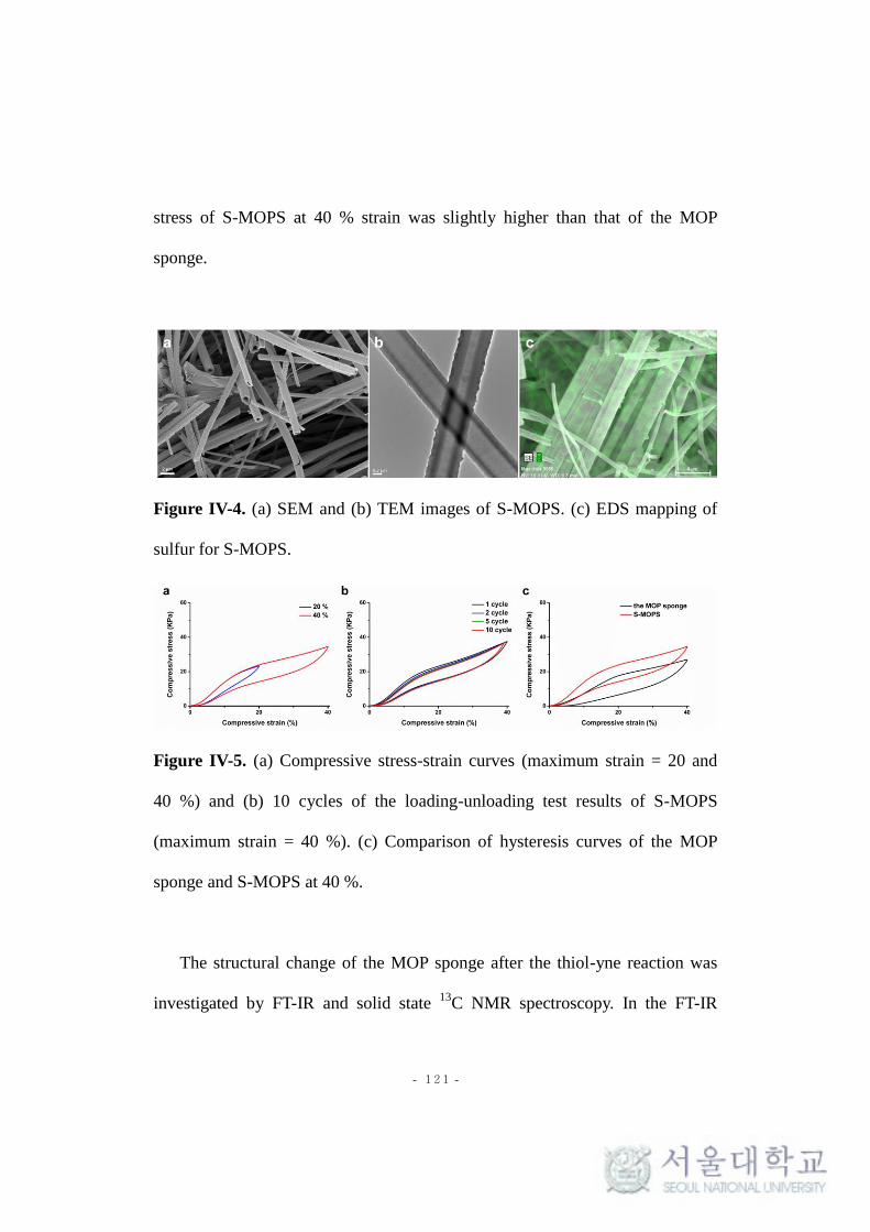
- 121 -
stress of S-MOPS at 40 % strain was slightly higher than that of the MOP
sponge.
Figure IV-4. (a) SEM and (b) TEM images of S-MOPS. (c) EDS mapping of
sulfur for S-MOPS.
Figure IV-5. (a) Compressive stress-strain curves (maximum strain = 20 and
40 %) and (b) 10 cycles of the loading-unloading test results of S-MOPS
(maximum strain = 40 %). (c) Comparison of hysteresis curves of the MOP
sponge and S-MOPS at 40 %.
The structural change of the MOP sponge after the thiol-yne reaction was
investigated by FT-IR and solid state 13
C NMR spectroscopy. In the FT-IR

- 122 -
spectrum of the MOP sponge, the -C≡C- band of substituted acetylene groups
and the C-H band of terminal acetylene groups appeared at 2222 and 3330 cm-1
,
respectively. After the thiol-yne reaction, the peak intensities of those bands
decreased considerably.[25,28]
Also, the peaks around 3000 cm-1
newly appeared,
which corresponded to the C-H band of propyl groups (Figure IV-6a). The solid
state 13
C NMR spectrum of S-MOPS showed the carbon peaks of propyl groups
at around 30 ppm (Figure IV-6b). The elemental analysis also confirmed the
presence of sulfur (14.1 wt%) (Table IV-1). All these results corroborated that
the MOP sponge was successfully functionalized by the thiol-yne
reaction.[25,28,31]
Both the MOP sponge and S-MOPS did not have discernible
crystalline peaks in the PXRD patterns (Figure IV-6c). Thermogravimetric
analysis showed (Figure IV-6d) that the MOP sponge was thermally stable up to
300 oC. The degradation of S-MOPS began earlier than the MOP sponge
probably due to the presence of propyl groups.[32]

- 123 -
Figure IV-6. (a) FT-IR spectra, (b) Solid state 13
C CP/MAS NMR spectra, (c)
PXRD patterns and (d) TGA thermograms of the MOP sponge and S-MOPS.
Table IV-1. Elemental compositions of the MOP sponge and S-MOPS
measured by elemental analysis.
C (wt%) H (wt%) S (wt%)
The MOP sponge 67.6 1.8 0
S-MOPS 66.4 2.6 14.1

- 124 -
The pore structures of the MOP sponge and S-MOPS were studied by N2
adsorption-desorption analysis at 77 K (Figure IV-7a, Table IV-2). The
Brunauer-Emmett-Teller (BET) surface area of the MOP sponge was 512 m2 g
-1.
After the thiol-yne reaction, the BET surface area of the MOP sponge was
increased to 649 m2 g
-1, which was unusual compared with the previous
reports.[25,28]
This result could be attributable to the favorable change in the pore
structure to the surface area where total pore and micropore volumes increased,
and an average pore size decreased by the post-reaction. NLDFT pore size
analysis (Figure IV-7b) revealed that mesopores in the range of 15 - 40 nm
found in the MOP sponge almost disappeared and more meso- and micropores
with a size of less than 10 nm formed after the thiol-yne reaction. We presumed
that the reaction of the alkyne groups of the MOP sponge with the dithiol
produced a more highly crosslinked network[31-33]
with an increase in the
micropore volume.

- 125 -
Figure IV-7. (a) N2 adsorption-desorption isotherms measured at 77 K and (b)
NLDFT pore size distributions of the MOP sponge and S-MOPS.
Table IV-2. Porosity data of the MOP sponge and S-MOPS.
SBET
a
m2 g
-1
Smicrob
m2 g
-1
Smicro/SBET Vtotal
c
cm3 g
-1
Vmicrod
cm3 g
-1
Vmicro/Vtotal
Pore
sizea
nm
the MOP
sponge 512 331 0.646 0.440 0.182 0.414 3.43
S-MOPS 649 487 0.750 0.472 0.235 0.498 2.91
aThe surface area and average pore size were calculated from N2 adsorption-
desorption isotherms by the BET method. bThe surface area from micropores
was calculated by the t-plot method. cPore volume at P/P0 = 0.99.
dPore volume
at P/P0 = 0.1.

- 126 -
IV-3-3. A Silver Decorated MOP Sponge as a Heterogeneous Catalyst
A monolithic heterogeneous catalyst was prepared by using the MOP
sponge as a support. The high porosity and compressibility of the MOP sponge
were expected to allow rapid absorption of organic reactants,[34-36]
which could
increase the efficiency of the catalytic reaction. Silver was chosen as a metal
catalyst, which is relatively cheap and shows excellent catalytic activity in
many organic reactions.[37,38]
A silver decorated MOP sponge as a
heterogeneous catalyst was prepared by in-situ growth of silver nanoparticles
inside the MOP sponge. Briefly, S-MOPS was immersed in a silver nitrate
solution, and compressed and released repeatedly to absorb Ag+ ions. The
subsequent reduction reaction with NaBH4 was carried out to produce the silver
nanoparticles supported on S-MOPS (S-MOPS-Ag).
Figure IV-8a and b show the SEM and TEM images of S-MOPS-Ag,
respectively. The EDS elemental mapping showed the even distribution of Ag
atoms inside the MOP sponge (Figure IV-8c). The average diameter of Ag
nanoparticles was 7.08 nm (Figure IV-8d).

- 127 -
Figure IV-8. (a) SEM image and the photograph (inset) of S-MOPS-Ag. (b)
TEM image and (c) EDS mapping of silver atoms for S-MOPS-Ag. (d)
Diameter distribution of Ag nanoparticles inside S-MOPS-Ag.
In the PXRD analysis of S-MOPS-Ag (Figure IV-9a), four sharp diffraction
peaks appeared at 2θ = 38, 44, 64 and 77o, which were indexed to the (111),
(200), (220) and (311) planes of cubic Ag, respectively.[38,39]
In the high-
resolution XPS spectrum, the peaks were observed at 368 and 374 eV,
corresponding to Ag 3d5/2 and Ag 3d3/2 binding energies, respectively (Figure
IV-9b). These results supported that Ag+ ions were successfully converted to

- 128 -
metallic Ag by the reduction reaction.[38,40]
The amount of Ag nanoparticle
loading inside S-MOPS-Ag was 5.39 wt% when calculated by ICP-MS analysis.
S-MOPS-Ag showed similar compressive stress-strain behaviors to S-MOPS
(Figure IV-10a). BET surface area of S-MOPS-Ag decreased slightly to 560 m2
g-1
from 649 m2 g
-1 of S-MOPS (Figure IV-10b).
[41]
Figure IV-9. (a) PXRD pattern of S-MOPS-Ag. (b) High-resolution XPS
spectrum of Ag3d region of S-MOPS-Ag.
Figure IV-10. (a) Compressive stress-strain curves (maximum strain = 40%)
and (b) N2 adsorption-desorption isotherms measured at 77 K of S-MOPS and
S-MOPS-Ag.

- 129 -
IV-3-4. Catalytic Ability Evaluation of S-MOPS-Ag for the Reduction of 4-
Nitrophenol
The catalytic activity of S-MOPS-Ag was evaluated in the reduction
reaction of 4-nitrophenol (4-NP) to 4-aminophenol by NaBH4.[33,40,41]
Because
of hydrophobicity of the MOP framework, a piece of monolithic S-MOPS-Ag
was first wetted with ethanol and then with water by solvent-exchange before
the catalytic reaction. A reaction solution was prepared by mixing aqueous 4-NP
and NaBH4 solutions, which showed an absorption maximum around 400 nm
due to the formation of 4-nitrophenolate.[40,41]
For the catalytic reaction to
proceed, S-MOPS-Ag was immersed in the reaction solution and manually
compressed and released with a rate of 3 s for the cycle. The progress of the
reduction reaction could be monitored by UV-Vis spectroscopy and the naked
eye (Figure IV-11a, b). The absorption peak intensity of 4-nitrophenolate at 400
nm was rapidly diminished, and a new peak developed around 300 nm. After
160 compression-release cycles, the peak intensity became weak, and the
initially reddish solution turned almost colorless, suggesting the near
completion of the reduction reaction.[40,41]
In contrast, the reaction occurred
very slowly when the reduction reaction was carried out without the

- 130 -
compression-release process. (Figure IV-11c, d). S-MOPS alone did not
catalyze the 4-NP reduction under the same experimental conditions (Figure IV-
12).
Figure IV-11. (a) UV-Vis spectra of the aqueous 4-NP solution (initial
concentration = 1 x 10⁻⁴
M) measured during the reaction with the compression
and release process. (b) Photographs of the 4-NP solution taken before and after
160 cycles of compression and release. UV-Vis spectra of the aqueous 4-NP
solution (initial concentration = 1 x 10⁻⁴
M) measured without the compression

- 131 -
and release process; (c) the reaction solution was not stirred and (d) the reaction
solution was stirred.
Figure IV-12. UV-Vis spectra of the aqueous 4-NP solution (initial
concentration = 1 x 10⁻⁴
M) measured during the reaction with the repeated
compression and release of S-MOPS.
Since a large excess of NaBH4 was used compared with 4-NP, the pseudo
first-order kinetic equation could be used to describe the overall reaction as
follows:
ln(Ct / C0) = - kt (1)

- 132 -
where Ct is the concentration of 4-NP at reaction time = t and C0 is the
initial concentration.[41]
All the reactions showed linear correlations between
ln(Ct / C0) and time (Figure IV-13). The apparent rate constant of the reaction
with the compression-release process was 7.61 x 10⁻³
s-1
, which was much
higher than those for the reactions without the compression-release process. The
increase in the reaction rate came from enhanced efficiency in fluid
exchange.[35,42]
Through the compression-release, the reactants had more
chances to contact with silver catalysts inside the MOP sponge. When S-
MOPS-Ag was simply immersed in the reaction solution, the reaction rate
would be governed by the slow diffusion of the reactants into the MOP sponge.
S-MOPS-Ag was easily removed from the reaction mixture owing to its
monolithic character and was reused after washing and drying. The 4-NP
reduction efficiency of S-MOPS-Ag was maintained around 95 % after 5 cycles
of the reactions (Figure IV-14).

- 133 -
Figure IV-13. Plots of - ln(Ct / C0) versus time during the catalytic reduction of
4-NP by S-MOPS-Ag under different reaction conditions. With the
compression-release process, the apparent rates constant (k) for the reaction =
7.61 x 10⁻³
s-1
. Without the compression and release process, k = 2.84 x 10⁻⁴
s-1
when the reaction solution was not stirred and k = 6.64 x 10⁻⁴
s-1
when the
reaction solution was stirred.
Figure IV-14. Change in the catalytic activity of S-MOPS-Ag during recycling.

- 134 -
IV-4. Conclusions
In conclusion, we fabricated a compressible and monolithic heterogeneous
catalyst based on the MOP sponge. The MOP sponge consisting of entangled
tubular MOP fibers was synthesized via a one-pot Sonogashira-Hagihara
coupling reaction. Sulfur groups were introduced to the MOP fibers by the
thiol-yne reaction with a dithiol. Ag nanoparticles were immobilized in the
MOP sponge by the in situ reduction of Ag+ ions. The MOP sponge-Ag
heterogeneous catalyst showed good catalytic ability and recyclability in the
reduction reaction of 4-NP. The MOP sponge with hierarchical porosity and the
ease of functionalization is a promising supporting material for noble metal
catalysts. In particular, the compressible and monolithic properties of the MOP
sponge make it an excellent candidate for use in a flow reactor and future
research will be focused in this direction.
IV-5. References
1. Gao, F.; Goodman, D. W. Annu. Rev. Phys. Chem. 2012, 63, 265–286.

- 135 -
2. Lu, J.; Toy, P. H. Chem. Rev. 2009, 109, 815–838.
3. Dawson, R.; Cooper, A. I.; Adams, D. J. Prog. Polym. Sci. 2012, 37,
530–563.
4. Xu, Y.; Jin, S.; Xu, H.; Nagai A.; Jiang, D. Chem. Soc. Rev., 2013, 42,
8012–8031.
5. Li, G.; Zhang, B.; Yan, J.; Wang, Z. J. Mater. Chem. A 2014, 2, 18881–
18888.
6. Li, G.; Zhang, B.; Wang, Z. Macromolecules 2016, 49, 2575–2581.
7. Chen, L.; Honsho, Y.; Seki, S.; Jiang, D. J. Am. Chem. Soc. 2010, 132,
6742–6748.
8. Jiang, J. X.; Su, F.; Trewin, A.; Wood, C. D.; Campbell, N. L.; Niu, H.;
Dickinson, C.; Ganin, A. Y.; Rosseinsky, M. J.; Khimyak, Y. Z.; Cooper,
A. I. Angew. Chemie. Int. Ed. 2007, 46, 8574–8578.
9. Schmidt, J.; Werner, M.; Thomas, A. Macromolecules 2009, 42, 4426–
4429.
10. Lim, H.; Chang, J. Y. Macromolecules, 2010, 43, 6943–6945.
11. Lim, H.; Cha, M. C.; Chang, J. Y. Polym. Chem. 2012, 3, 868–870.
12. Yang, Z.; Zhang, H.; Yu, B.; Zhao, Y.; Ma, Z.; Ji, G.; Han, B.; Liu, Z.
Chem. Commun. 2015, 51, 11576–11579.
13. Liu, J.; Tobin, J. M.; Xu, Z.; Vilela, F. Polym. Chem. 2015, 6, 7251-

- 136 -
7255.
14. Zhuang, X.; Gehrig, D.; Forler, N.; Liang, H.; Wagner, M.; Hansen, M.
R.; Laquai, F.; Zhang, F.; Feng, X. Adv. Mater. 2015, 27, 3789–3796.
15. Cha, M. C.; Lim, Y.; Chang, J. Y. J. Polym. Sci. Part A Polym. Chem.
2015, 59, 2336–2342.
16. Zhang, L.; Wang, K.; Qian, X.; Liu, H.; Shi, Z. ACS Appl. Mater.
Interfaces 2013, 5, 2761–2766.
17. Lim, Y.; Cha, M. C.; Chang, J. Y. Sci. Rep. 2015, 5, 15957.
18. Ruan, C.; Ai, K.; Li, X.; Lu, L. Angew. Chemie. Int. Ed. 2014, 53,
5556–5560.
19. Chen, X.; Weibel, J. A.; Garimella, S. V. Ind. Eng. Chem. Res. 2016, 55,
3596−3602.
20. Ye, K.; Zhang, D.; Zhang, H.; Cheng, K.; Wang, G.; Cao, D.
Electrochim. Acta 2015, 178, 270–279.
21. García-Moreno, F. Materials 2016, 9, 20–24.
22. Chun, J.; Park, J. H.; Kim, J.; Lee, S. M.; Kim, H. J.; Son, S. U. Chem.
Mater. 2012, 24, 3458-3463.
23. Kang, N.; Park, J. H.; Choi, J.; Jin, J.; Chun, J.; Jung, I. G.; Jeong, J.;
Park, J. G.; Lee, S. M.; Kim, H. J.; Son, S. U. Angew. Chem. Int. Ed.
2012, 51, 6626-6630.

- 137 -
24. Chen, Y.; Sun, H.; Yang, R.; Wang, T.; Pei, C.; Xiang, Z.; Zhu, Z.; Liang,
W.; Li, A.; Deng, W. J. Mater. Chem. A 2015, 3, 87-91.
25. Urakami, H.; Zhang, K.; Vilela, F. Chem. Commun. 2013, 49, 2353–
2355.
26. Islamoglu, T.; Kim, T.; Kahveci, Z.; El-Kadri, O. M.; El-Kaderi, H. M.
J. Phys. Chem. C 2016, 120, 2592–2599.
27. Ghasimi, S.; Landfester, K.; Zhang, K. A. I. ChemCatChem 2016, 8,
694–698.
28. Kiskan, B.; Weber, J. ACS Macro Lett. 2012, 1, 37–40.
29. Cliffel, D. E.; Zamborini, F. P.; Gross, S. M.; Murray, R. W. Langmuir
2000, 16, 9699–9702.
30. Cargnello, M.; Wieder, N. L.; Canton, P.; Montini, T.; Giambastiani, G.;
Benedetti, A.; Gorte, R. J.; Fornasiero, P. A. Chem. Mater. 2011, 23,
3961–3969.
31. Pötzsch, R.; Komber, H.; Stahl, B. C.; Hawker, C. J.; Voit, B. I.
Macromol. Rapid Commun. 2013, 34, 1772–1778.
32. Wei, Q.; Pötzsch, R.; Komber, H.; Pospiech, D.; Voit, B. Polymer 2014,
55, 5600–5607.
33. Lee, H.; Kim, H.; Choi, T. J.; Park, H. W.; Chang, J. Y. Chem. Commun.
2015, 51, 9805-9808.

- 138 -
34. Pan, Y.; Liu, Z.; Wang, W.; Peng, C.; Shi, K.; Ji, X. J. Mater. Chem. A
2016, 4, 2537-2549.
35. Zhao, J.; Ren, W.; Cheng, H. M. J. Mater. Chem. 2012, 22, 20197–
20202.
36. Lin, K. Y. A.; Chang, H. A. J. Mater. Chem. A 2015, 3, 20060-20064.
37. Chi, Y.; Tu, J.; Wang, M.; Li, X.; Zhao, Z. J. Colloid Interface Sci. 2014,
423, 54–59.
38. Liang, K.; Li, X.; Kang, S. Z.; Qin, L.; Li, G.; Mu, J. Carbon 2014, 80,
716–724.
39. Mnasri, N.; Charnay, C.; De Ménorval, L. C.; Moussaoui, Y.; Elaloui,
E.; Zajac, J. Microporous Mesoporous Mater. 2014, 196, 305–313.
40. Xiao, W.; Zhang, Y.; Liu, B. ACS Appl. Mater. Interfaces 2015, 7,
6041–6046.
41. Qian, H.; He, Q.; Zheng, J.; Li, S.; Zhang, S. Polymer 2014, 55, 550–
555.
42. Wu, K.; Guo, J.; Wang, C. Angew. Chemie. Int. Ed. 2016, 55, 1–6.

- 139 -
Chapter V.
A Hierarchically Porous Polyimide Composite Prepared
by One-Step Condensation Reaction inside a Sponge for
Heterogeneous Catalysis

- 140 -
V-1. Introduction
Heterogeneous catalysts are widely used in the chemical industry owing to
their advantages of easy separation from products, recyclability, and
applicability to continuous flow processes.[1,2]
Supported catalysts are an
important class of heterogeneous catalysts, where catalytically active species
are immobilized in porous supporting materials such as activated carbons,
mesoporous silica, and metal oxides.[3-6]
A large surface area and high porosity
of the supporting materials can improve the dispersion of active species and the
accessibility of reactants to the active sites.[3,4]
In recent years, a number of
heterogeneous catalysts based on microporous organic polymers (MOPs) have
been reported.[7-11]
MOPs have an advantage as a supporting material compared
with inorganic supports such that specific functionality can be easily introduced
to them for favorable interactions with active species.
Sponges are a class of materials which have highly interconnected open
cellular structures. They have good mechanical stability, compressibility, and
processability. However, because sponges have large pores and low surface
areas, they are mainly used for removing liquids by absorption. Recently
functional sponge composites have attracted considerable interest, which are
prepared by the incorporation of functional constituents into the sponges.
Functional sponge composites have various applications such as absorption,[12]

- 141 -
filtration,[13]
fuel cells,[14]
flow reactors,[15,16]
pollutant removal,[17-20]
and
catalysis.[21]
In this study, we prepared a hierarchically porous polyimide
composite by in situ polymerization inside a synthetic sponge. Aromatic
polyimides are an important class of high performance polymers due to their
rigid structures and thermal stability.[22-25]
We synthesized a microporous
aromatic polyimide with metal coordination sites using an aminophenanthroline
as a functional comonomer. When the reaction was carried out inside a
melamine sponge, a hierarchically porous and compressible composite was
obtained. A heterogeneous catalyst was prepared by coordination with Pd(II)
ions, and its catalytic activity was evaluated in a Suzuki coupling reaction.

- 142 -
V-2. Experimental
Materials. Isoquinoline (97 %), palladium chloride (PdCl2) (59 wt% Pd),
phenylboronic acid (98%, containing anhydride), and 4’-bromoacetophenone
(98 %) were purchased from ACROS Organics. 1,3,5-Tris(4-aminophenyl)
benzene (> 93 %), pyromellitic dianhydride (98 %), and 4-bromoanisole (97 %)
were obtained from Tokyo Chemical Industry. 5-Amino-1,10-phenanthroline
(97 %) was purchased from Sigma-Aldrich. Potassium carbonate (K2CO3) was
obtained from Daejung Chemicals & Metals Co. The melamine sponge was
obtained from BASF Co. Other solvents were purchased from Junsei Chemical.
All materials were used without further purification.
Preparation of the Melamine Sponge/Microporous Polyimide
Composite (MS/MPI-Phen) and the Microporous Polyimide (MPI-Phen).
1,3,5-Tris(4-aminophenyl)benzene (84.3 mg, 0.24 mmol) and 5-amino-1,10-
phenanthroline (35.1 mg, 0.18 mmol) were dissolved in a mixture of N-methyl-
2-pyrrolidone (4 mL), mesitylene (4 mL), and isoquinoline (0.4 mL) in a 20 mL
vial. After dissolving pyromellitic dianhydride (98.2 mg, 0.45 mmol) in the
solution, a piece of melamine sponge (25.0 mg) was immersed and then heated
at 100 oC for 1 h and 160
oC for 24 h without stirring. The resulting composite
(MS/MPI-Phen) was washed with acetone and THF and dried under vacuum at

- 143 -
room temperature.
The microporous polyimide containing phenanthroline groups (MPI-Phen)
was prepared in the same manner except that a piece of melamine sponge was
absent in the polymerization solution.
Immobilization of Pd(II) Ions onto MS/MPI-Phen (MS/MPI-Phen-Pd).
PdCl2 (100 mg) was dissolved in acetonitrile (30 mL) at 90 oC. MS/MPI-Phen
(150 mg) was immersed in the solution and heated at 90 oC for 24 h with
stirring. The resultant composite was washed with acetonitrile and dried under
vacuum at 70 oC.
Suzuki Coupling Reaction Catalyzed by MS/MPI-Phen-Pd. A small
piece of MS/MPI-Phen-Pd (20.0 mg) and K2CO3 (276 mg, 2 mmol) were added
to a solution of a bromophenyl derivative (1 mmol) and phenylboronic acid
(146 mg, 1.2 mmol) in 8 mL of an aprotic solvent. The mixture was stirred at 95
oC for 24 h. After the removal of the catalyst, the reaction mixture was
concentrated by evaporation. The product yield was determined by analyzing
the reaction mixture with 1H NMR spectroscopy. The catalyst was reused after
washing with H2O, ethanol, and THF and drying.

- 144 -
Instrumental Characterization. FT-IR spectra were measured by a Nicolet
6700 FT-IR Spectrometer. 1H NMR spectra were recorded on a Bruker Avance-
300 spectrometer (300 MHz). Solid-state 13
C NMR spectrum was recorded on a
Bruker Avance II spectrometer (125 MHz). Powder X-ray diffraction (PXRD)
patterns were observed using a New D8 Advance (Cu Kα radiation, λ = 1.54 Å).
X-ray photoelectron spectroscopy (XPS) was measured by a KRATOA AXIS-
His spectrometer equipped with a Mg Ka X-ray source. Scanning electron
microscopy (SEM) images were obtained by a Carl Zeiss SUPRA 55VP.
Energy-dispersive X-ray spectroscopy (EDS) elemental map was obtained
using an Oxford instrument X-MaxN detector and analyzed with an Aztec
Energy EDS analyzer. Thermogravimetric analyses (TGA) were performed on a
TA modulated TGA2050 with a heating rate of 10 °C/min under nitrogen. N2
adsorption-desorption isotherms were investigated by a Belsorp-Max (BEL
Japan, Inc.) apparatus. The compression tests were performed by an Instron
5543 universal testing machine. A cylindrical sponge having a diameter of 16
mm and height of 15 mm was used for the measurement. The strain-stress
curves were measured at a strain rate of 3 mm min-1. Inductively coupled
plasma mass spectrometry (ICP-MS) was measured using a Varian 820-MS to
calculate a weight percentage of Pd(II) in the sponge. Pd ions were dissolved in
strong nitric acid before measurement.

- 145 -
V-3. Results and Discussion
V-3-1. Synthesis and Characterizations of MPI-Phen
A microporous polyimide containing phenanthroline groups as metal
binding sites (MPI-Phen) was synthesized as insoluble powders by the
condensation reaction of 1,3,5-tris(4-aminophenyl)benzene, pyromellitic
dianhydride, and 5-amino-1,10-phenanthroline (Scheme V-1). The molar ratio
of the triamine, dianhydride, and phenanthroline was controlled to be 8:15:6,
where the number of amine groups was equivalent to the number of anhydride
groups. When the ratio of the phenanthroline increased, the BET surface area of
the polymer sharply decreased.

- 146 -
Scheme V-1. Synthesis of a microporous polyimide containing phenanthroline
groups (MPI-Phen).
The molecular structure of MPI-Phen was characterized by FT-IR and solid
13C NMR spectroscopy. The FT-IR spectrum of MPI-Phen showed the
symmetric and asymmetric vibration peaks of the imide carbonyl groups at
1721 and 1780 cm-1
, respectively (Figure V-1a). The C-N-C stretching peak of

- 147 -
the heterocyclic imide rings appeared at 1356 cm-1
.[24,26]
In the 13
C NMR
spectrum, the aromatic carbon peaks were observed between 110 and 145 ppm
(Figure V-1b) and the peak at 164 ppm was assigned to the imide carbonyl
groups. The small peak at 174 ppm was assigned to the amide carbonyl groups
of uncyclized amic acid moieties.[26]
The PXRD pattern of MPI-Phen did not
show any discernible peaks, implying the amorphous nature of the polymer
(Figure V-1c). The presence of the phenanthroline group in MPI-Phen was
confirmed by XPS analysis. Two deconvoluted peaks centered at 400.5 eV and
398.7 eV were observed in the XPS spectrum for the N1s region (Figure V-1d),
which corresponded to the nitrogens of imide[27]
and phenanthroline groups,
respectively.[28,29]
From these results, we concluded that the microporous
polyimide containing phenanthroline groups were successfully prepared.

- 148 -
Figure V-1. (a) FT-IR spectra, (b) Solid state 13
C CP/MAS NMR spectra and
(c) PXRD pattern of MPI-Phen. (d) High-resolution XPS spectra of N 1s from
MPI-Phen.
The nitrogen adsorption-desorption analysis of MPI-Phen showed both type
I and type IV physisorption isotherms, indicating the presence of micro- and
mesopores (Figure V-2).[30]
The BET surface area of MPI-Phen was 723 m2g
-1,
which was comparable with those of previously reported microporous
polyimides.[31,32]

- 149 -
Figure V-2. N2 adsorption-desorption isotherms of MPI-Phen.
V-3-2. Fabrication and Characterizations of MS/MPI-phen
A polyimide composite with hierarchical porosity (MS/MPI-Phen) was
prepared by in situ polymerization inside a melamine sponge. The
polymerization was carried out in the same manner as described for MPI-Phen
except that a cylindrical melamine sponge was immersed in the polymerization
solution. The color of the melamine sponge turned from white to yellowish
brown, indicating the incorporation of MPI-Phen (Figure V-3). MS/MPI-Phen
could be cut into any shape with a knife.
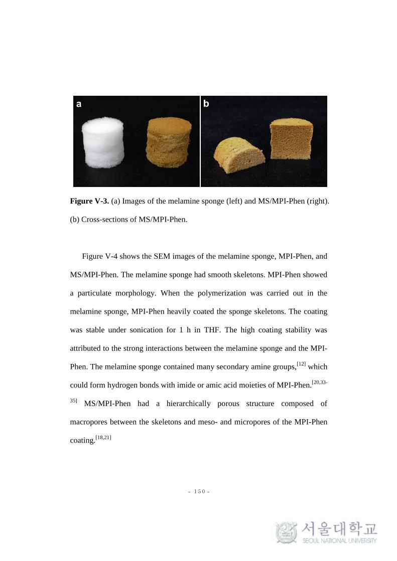
- 150 -
Figure V-3. (a) Images of the melamine sponge (left) and MS/MPI-Phen (right).
(b) Cross-sections of MS/MPI-Phen.
Figure V-4 shows the SEM images of the melamine sponge, MPI-Phen, and
MS/MPI-Phen. The melamine sponge had smooth skeletons. MPI-Phen showed
a particulate morphology. When the polymerization was carried out in the
melamine sponge, MPI-Phen heavily coated the sponge skeletons. The coating
was stable under sonication for 1 h in THF. The high coating stability was
attributed to the strong interactions between the melamine sponge and the MPI-
Phen. The melamine sponge contained many secondary amine groups,[12]
which
could form hydrogen bonds with imide or amic acid moieties of MPI-Phen.[20,33-
35] MS/MPI-Phen had a hierarchically porous structure composed of
macropores between the skeletons and meso- and micropores of the MPI-Phen
coating.[18,21]

- 151 -
Figure V-4. SEM images of (a), (b) the melamine sponge, (c), (d) MPI-Phen
and (e), (f) MS/MPI-Phen.
The TGA measurement showed that MPI-Phen had high thermal stability up
to 500 oC, while the melamine sponge started to degrade at 300 oC (Figure V-5).
The char yields of the melamine sponge, MPI-Phen, and MS/MPI-Phen at 800
oC were 5.9, 63.1 and 45.9 wt%, respectively. The amount of MPI-Phen (M)

- 152 -
incorporated into MS/MPI-Phen was estimated to be 69.9 wt% using the
following equation[20]
:
C1 x (M / 100) + C2 x (100 - M) / 100 = C3 (1)
where C1, C2 and C3 are the char yields of MPI-Phen, the melamine sponge,
and MS/MPI-Phen, respectively.
Figure V-5. TGA thermograms of the melamine sponge, MPI-Phen and
MS/MPI-Phen.
Figure V-6a shows nitrogen adsorption-desorption isotherms of the
melamine sponge, MPI-Phen, MS/MPI-Phen measured at 77 K. The BET

- 153 -
surface area of MS/MPI-Phen was 524 m2g
-1, which was slightly smaller than
that of MPI-Phen (723 m2g
-1) due to the presence of the melamine sponge
containing no micro- and mesopores. The non-local density functional theory
(NLDFT) pore size distribution curve of MS/MPI-Phen was similar to that of
MPI-Phen (Figure V-6b), suggesting that the growth of MPI-Phen on the
sponge skeleton did not significantly affect its pore structure.[20]
Figure V-6. (a) N2 adsorption-desorption isotherms of the melamine sponge,
MPI-Phen, and MS/MPI-Phen. (b) NLDFT pore size distributions of MPI-Phen
and MS/MPI-Phen.
MS/MPI-Phen was reversibly compressible (Figure V-7a). It showed the
higher compressive strength than the melamine sponge (Figure V-7b, c),
indicating the reinforcement by the microporous polymer.[17]
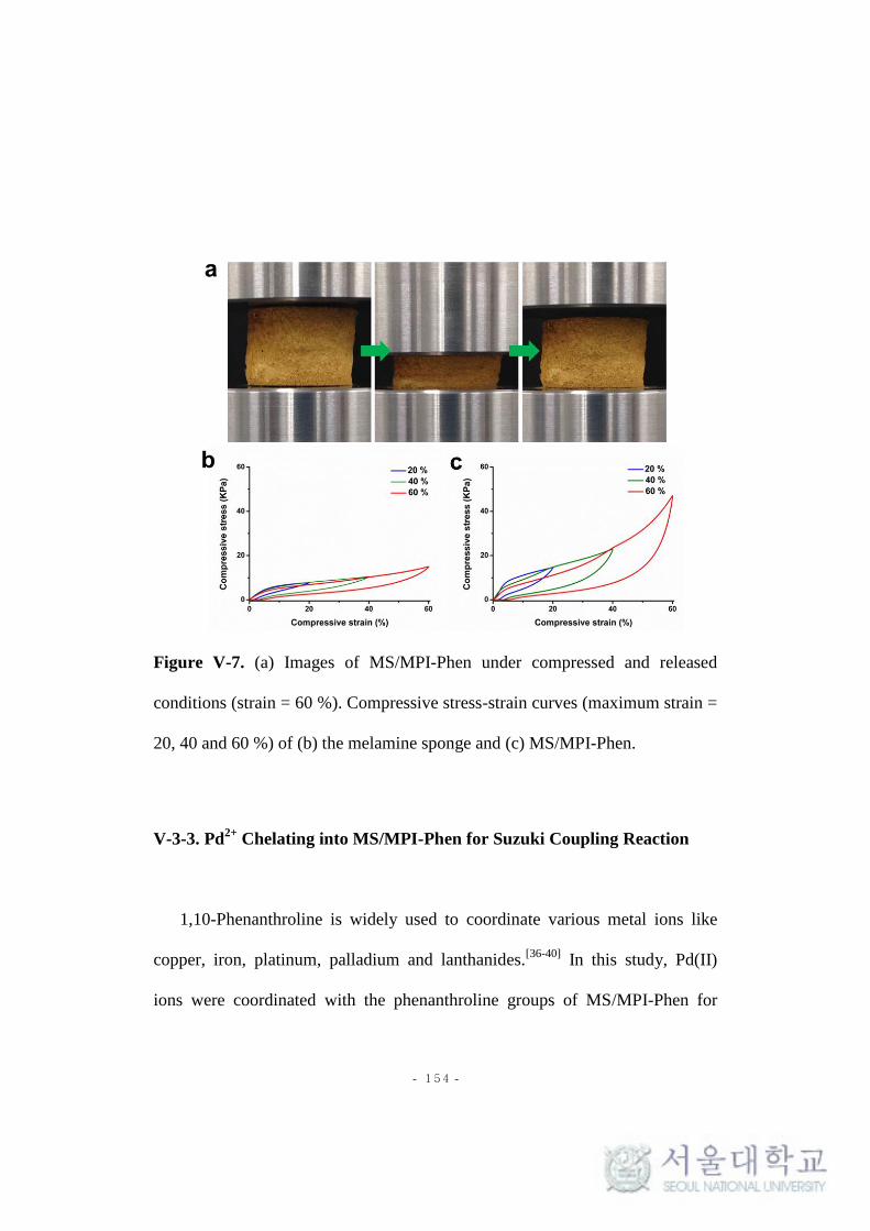
- 154 -
Figure V-7. (a) Images of MS/MPI-Phen under compressed and released
conditions (strain = 60 %). Compressive stress-strain curves (maximum strain =
20, 40 and 60 %) of (b) the melamine sponge and (c) MS/MPI-Phen.
V-3-3. Pd2+
Chelating into MS/MPI-Phen for Suzuki Coupling Reaction
1,10-Phenanthroline is widely used to coordinate various metal ions like
copper, iron, platinum, palladium and lanthanides.[36-40]
In this study, Pd(II)
ions were coordinated with the phenanthroline groups of MS/MPI-Phen for

- 155 -
heterogeneous catalysis.[41]
Figure V-8 shows the SEM, EDS, and XPS analysis
results. The microstructural morphology of the sponge was not changed after
the coordination (Figure V-8a). The EDS analysis revealed that Pd species were
uniformly distributed over the MPI-Phen coating (Figure V-8b, c). The
concentration of Pd(II) ions in MS/MPI-Phen-Pd was 0.53 wt% when measured
by ICP-MS. In the XPS analysis (Figure V-8d), MS/MPI-Phen-Pd exhibited
two peaks centered at 343.4 eV and 338.1 eV, which came from Pd 3d3/2 and Pd
3d5/2 of PdCl2, respectively.[42]

- 156 -
Figure V-8. (a) SEM image and (b) EDS spectrum of MS/MPI-Phen-Pd. (c)
EDS mapping of Pd atom for MS/MPI-Phen-Pd. (d) High-resolution XPS
spectrum of Pd 3d region of MS/MPI-Phen-Pd.
The catalytic activity of MS/MPI-Phen-Pd was evaluated for Suzuki
coupling reactions between bromobenzene and phenylboronic acid (Scheme V-
2). The reaction was carried out in an aprotic solvent such as toluene, 4-dioxane,
THF, and DMF using K2CO3 as a base. As shown in Table V-1, the product
yield was the highest in toluene. When the reaction was performed in an
aqueous base, the degradation of the imide structure was found.[43-45]
Suzuki

- 157 -
coupling reactions with bromobenzene derivatives such as using 4-
bromoanisole and 4-bromoacetophene were also catalyzed by MS/MPI-Phen-
Pd. After the 24 h reaction, the conversion yields of 4-bromoanisole and 4-
bromoacetophene were 79.0 % and 70.1 %, respectively.
Scheme V-2. Suzuki coupling reaction between bromobenzene and
phenylboronic acid in the presence of MS/MPI-Phen-Pd

- 158 -
Table V-1. Suzuki coupling reaction results in different reaction solvents.
Entry Solvent Yield (%)a
1b Toluene 83.3
2b 1,4-Dioxane 54.1
3c THF 27.6
4b DMF No reaction
Reaction conditions: 1.0 mmol of bromobenzene, 1.2 mmol of phenylboronic
acid, 2.0 mmol of K2CO3, 20 mg of MS/MPI-Phen-Pd, 8 mL of a solvent, 24 h.
aThe yield was determined by the
1H NMR analysis of the reaction mixture.
bReaction under 95
oC.
cReaction under reflux.
After the reaction, MS/MPI-Phen-Pd was easily removed from the reaction
mixture because of its monolithic character. The recycling test showed that the
yields of the coupling reaction between bromobenzene and phenylboronic acid
decreased to 75.9 % and 56.6 % in the 2nd and 3rd cycles, respectively. This
result could be due to the leaching of Pd(II) ions during recycling.

- 159 -
V-4. Conclusions
In conclusion, we demonstrated the fabrication of a microporous polyimide
composite by the one-step condensation reaction of an aromatic triamine and an
aromatic dianhydride in a melamine sponge. Metal binding groups could be
incorporated into the composite using a functional aromatic amine as a
comonomer. The composite had a core-shell structure, where the sponge
skeleton was coated with the microporous polyimide due to strong interactions
between the melamine and the polyimide units. As a result, the composite
possessed a hierarchically porous structure, composed of micro- and mesopores
in the polyimide coating and macropores formed by the sponge skeletons. The
composite could be prepared in any size and shape. These characteristics
together with the metal binding functionality made the composite a promising
support material for heterogeneous catalysis. The approach presented here
would be expanded to prepare compressible and hierarchically porous
monoliths having various functionalities.
V-5. References
1. Coperet, C.; Comas-Vives, A.; Conley, M. P.; Estes, D. P.; Fedorov, A.;

- 160 -
Mougel, V.; Nagae, H.; Nunez-Zarur, F.; Zhizhko, P. A. Chem. Rev.
2016, 116, 323-421.
2. Cole-Hamilton, D. J. Science, 2003, 299, 1702-1706.
3. Puthiaraj, P.; Lee, Y. R.; Zhang, S.; Ahn, W. S. J. Mater. Chem. A 2016,
4, 16288-16311.
4. Price, P. M.; Clark, J. H.; Macquarrie, D. J. J. Chem. Soc., Dalton
Trans., 2000, 101-110.
5. Zheng, H.; Gao, F.; Valtchev, V. J. Mater. Chem. A, 2016, 4, 16756-
16770.
6. Dhakshinamoorthy, A.; Garcia, H. Chem. Soc. Rev. 2012, 41, 5262-
5284.
7. Shultz, A. M.; Farha, O. K.; Hupp, J. T.; Nguyen, S. T. Chem. Sci. 2011,
2, 686-689.
8. Jiang, J. X.; Wang, C.; Laybourn, A.; Hasell, T.; Clowes, R.; Khimyak,
Y. Z; Xiao, J.; Higgins, S. J.; Adams, D. J.; Cooper, A. I. Angew. Chem.
Int. Ed. 2011, 50, 1072-1075.
9. Liang, Q.; Liu, J.; Wei, Y.; Zhao, Z.; MacLachlan, M. J. Chem. Commun.
2013, 49, 8928-8930.
10. Zhao, X.; Yan, N. RSC Adv. 2015, 5, 69955-69961.
11. Liras, M.; Iglesias, M.; Sanchez, F. Macromolecules, 2016, 49, 1666-

- 161 -
1673.
12. Pham, V. H.; Dickerson, J. H. ACS Appl. Mater. Interfaces 2014, 6,
14181-14188.
13. Li, H.; Gui, X.; Zhang, L.; Wang, S.; Ji, C.; Wei, J.; Wang, K.; Zhu, H.;
Wu, D.; Cao, A. Chem. Commun. 2010, 46, 7966-7968.
14. Zhao, L.; Sui, X.-L.; Li, J.-L.; Zhang, J.-J.; Zhang, L.-M.; Wang, Z.-B.
ACS Appl. Mater. Interfaces 2016, 8, 16026-16034.
15. Uemura, S.; Suzuki, S.; Abe, K.; Kubota, K.; Yamaguchi, T.; Ohashi,
A.; Takemura, Y.; Harada, H. Bioresor. Technol. 2010, 101, 5180-5185.
16. Yu, X. -F.; Mao, L. -B.; Ge, J.; Yu, Z. -L.; Liu, J. -W.; Yu, S. -H. Sci.
Bull. 2016, 61, 700-705.
17. Yang, Y.; Shi, E.; Li, P.; Wu, D.; Wu, S.; Shang, Y.; Xu, W.; Cao, A.;
Yuan, Q. Nanoscale 2014, 6, 3585-3592.
18. Andrew Lin, K. -Y. ; Chang, H. A J. Mater. Chem. A 2015, 3, 20060-
20064.
19. Lim, Y.; Cha, M. C.; Chang, J. Y. Sci. Rep. 2015, 5, 15957.
20. Kim, J. G.; Choi, T. J.; Chang, J. Y. Chem. Eng. J. 2016, 306, 242-250.
21. Wu, K.; Guo, J.; Wang, C. Angew. Chem. Int. Ed. 2016, 55, 1-6.
22. Li, G.; Wang, Z. Macromolecules 2013, 46, 3058-3066.
23. Yang, Y.; Zhang, Q.; Zhanga, Z.; Zhang, S. J. Mater. Chem. A 2013, 1,

- 162 -
10368-10374.
24. Kim, Y. J.; Jeong, Y. G. Macromol. Res. 2015, 23, 1144-1151.
25. Tundidor-Camba, A.; Terraza, C. A.; Tagle, L. H.; Coll, D.; Ortiz, P.;
Pérez, G.; Jessop, I. A. Macromol. Res. 2017, doi: 10.1007/s13233-017-
5029-5.
26. Wang, Z.; Zhang, B.; Yu, H.; Li, G.; Bao, Y. Soft Matter 2011, 7, 5723-
5730.
27. Ektessabi, A. M.; Hakamata, S. Thin Solid Films 2000, 377-378, 621-
625.
28. Stańczyk, K.; Dziembaj, R.; Piwowarska, Z.; Witkowski, S. Carbon
1995, 33, 1383-1392.
29. Ren, C.; Li, H.; Li, R.; Xu, S.; Wei, D.; Kang, W.; Wang, L.; Jia, L.;
Yanga, B.; Liu, J. RSC Adv. 2016, 6, 33302-33307.
30. Sing, K. S. W.; Everett, D. H.; Haul, R. A. W.; Moscou, L,; Pierotti, R.
A.; Rouquérol, J.; Siemieniewska, T. Pure Appl. Chem. 1985, 57, 603-
619.
31. Wang, Z.; Zhang, B.; Yu, H.; Li, G.; Bao, Y. Soft Matter 2011, 7, 5723-
5730.
32. Liebl, M. R.; Senker, J. Chem. Mater. 2013, 25, 970-980
33. Liu, Z.; Miao, Y. E.; Liu, M.; Ding, Q.; Tjiu, W. W.; Cui, X.; Liu, T. J.

- 163 -
Colloid Interf. Sci. 2014, 424, 49-55.
34. Benson, R. S.; Lee, M. W.; Grummitt, D. W. Nanostruct. Mater. 1995, 6,
83-91.
35. Liu, X.; Gao, G.; Dong, L.; Gu, G. Y, Y. Polym. Adv. Technol. 2009, 20,
362-366.
36. Accorsi, G.; Listorti, A.; Yoosaf, K.; Armaroli, N. Chem. Soc. Rev. 2009,
38, 1690-1700.
37. Pallenberg, A. J.; Koenig, K. S.; Barnhart, D. M. Inorg. Chem. 1995, 34,
2833-2840.
38. Dai, Z.; Chen, F.; Sun, Q.; Ji, Y.; Wang, L.; Meng, X.; Xiao, F. S.
Chinese J. Chem. 2016, 37, 54-60.
39. Chen, Z.; Li, X.; Jin, X.; Shi, L.; Liu, M.; Sun, Z.; Lu, J. Macromol. Res.
2015, 23, 830-837.
40. Ren, J.; Gu, J.; Tao, L.; Zhang, G.; Yang, W. Macromol. Res. 2016, 24,
502-507.
41. Magano, J.; Dunetz, J. R. Chem. Rev. 2011, 111, 2177-2250.
42. Kumar, G.; Blackburn, J. R.; Albridge, R. G.; Moddeman, W. E.; Jones,
M. M. Inorg. Chem. 1972, 11, 296-300.
43. Stoffel, N. C.; Hsieh, M.; Chandra, S.; Kramer, E. J. Chem. Mater. 1996,
8, 1035-1041.

- 164 -
44. Stephans, L. E.; Myles, A.; Thomas, R. R. Langmuir 2000, 16, 4706-
4710.
45. Lee, J.; Chang, J. Y. Chem. Comm. 2016, 52, 10419-10422.

- 165 -
국문요약
마이크로기공성 고분자는 넓은 표면적, 저밀도, 마이크로기공성,
물리화학적 안정성 등 우수한 특성을 갖고 있다. 또한 반응물질의
선택이나 후처리를 통해 마이크로기공성 고분자 내부에 다양한
기능성을 부여할 수 있어 여러 분야에서의 활용이 가능하다. 하지만
대부분의 마이크로기공성 고분자는 가교결합 구조를 갖는 불용성의
가루형태로 얻어져 나쁜 가공성을 갖는다. 본 연구에서는 물리적
형태의 조절이 가능한 기능성 마이크로기공성 고분자들을 제조하고
이들을 불균질 촉매의 제조와 염료의 흡착에 활용하였다.
첫 번째로 고분자의 합성과정에 전기방사 나노섬유를 분산시키어
나노섬유로 강화된 마이크로기공성 고분자 스펀지를 제조했다. 2,5-
Dibromoaniline과 1,3,5-triethynylbenzene의 소노가시라-하기하라 반응을
나노섬유 (PVASi)의 존재 하에 진행하여 코어셸 나노섬유 구조를
갖는 압축성 스펀지 (PVASi@TEDB-NH2) 를 얻었다. 고분자는
나노섬유의 표면에서 균일하게 자랐으며 이는 고분자가 갖고 있는
아민기가 PVASi 표면의 하이드록실기와 수소결합을 형성하기
때문이다. PVASi@TEDB-NH2는 30.4 mg cm-3의 평균 밀도와 447 m
2g
-1의
- 166 -
BET 표면적을 보였다. 복합체 스펀지는 물 속의 유기 염료를
제거하는데 사용하였으며 반복적인 압축을 통하여 염료의 빠른
제거가 가능하였다.
두 번째로, hypercrosslinked 고분자 (HCP)를 기반으로 한
마이크로기공성 촉매막을 제조하였다. 아민 작용기가 도입된
폴리아크릴로나이트릴 (APAN) 나노섬유 막을 기질로 이용하고 1,1’-
bi-2-naphthol의 프리델-크래프츠 반응을 수행하여 HCP를 기반으로 한
나노섬유 막을 합성하였다. HCP는 APAN 나노섬유의 표면에서
균일하게 자라나 막에 위계적 기공성을 부여하였다. HCP를 기반으로
한 마이크로기공성 막은 우수한 기계적 강도와 마이크로기공성을
가졌고 BET 표면적은 375 m2g
-1이었다. 막 내부에서 팔라듐
나노입자를 성장시키어 HCP를 기반으로 한 마이크로기공성 촉매막
(APAN-HCP-Pd) 을 제조한 후 촉매특성을 4-nitrophenol의 환원반응을
통해 평가하였다.
세 번째로, 마이크로기공성 나노튜브 스펀지를 이용한 압축성
단일체 촉매를 제조하였다. 1,4-Diiodotetrafluorobenzene과 1,3,5-
triethynylbenzene의 소노가시라-하기하라 반응을 톨루엔과
트리에틸아민(2:1, 부피비율)의 혼합용액에서 교반하지 않고 진행하여

- 167 -
마이크로기공성 단일체 스펀지를 합성하였다. 이 스펀지는 수백
나노미터의 직경을 가진 튜브구조의 고분자 섬유들이 서로 엉키어
있는 흥미로운 마이크로구조를 보였으며 512 m2g
-1의 BET 표면적과
위계적 기공성을 가졌다. 싸이올-인 반응을 통하여 마이크로기공성
스펀지에 황 작용기를 도입하였다. 개질된 마이크로기공성 스펀지의
BET 표면적은 반응 전보다 13% 높아졌는데 이는 싸이올-인 반응에
의한 마이크로기공의 증가 때문이다. 황으로 개질된 마이크로기공성
스펀지 내부에 은 나노입자를 성장시키어 마이크로기공성 스펀지-은
불균질 촉매 (S-MOP-Ag) 를 제조한 후 4-nitrophenol 수용액의 환원
반응에 이용하여 촉매 특성을 조사하였다. S-MOP-Ag의 반복적인
압축을 수행하면 촉매 반응 속도가 크게 증가하였다. S-MOP-Ag는
단일체적 성질 때문에 반응 용액으로부터 회수가 용이하였고 세척과
건조 후에 재사용이 가능하였다.
마지막으로, 금속이온을 고정할 수 있는 작용기를 가진 압축성
폴리이미드 스펀지를 멜라민 스펀지 내부에서의 중합 반응을 통해
제조하였다. 1,3,5-Tris(4-aminophenyl)benzene과 pyromellitic dianhydride를
마이크로기공성 고분자의 주 단량체로 사용하고, 5-amino-1,10-
phenanthroline을 기능성 단량체로 사용하였다. Phenanthroline 작용기를

- 168 -
지닌 폴리이미드 (MPI-Phen) 은 불용성의 가루형태로 얻어졌으나
멜라민 스펀지의 존재 하에서 중합할 경우, 스펀지의 골격 위에서
코팅 층을 형성하였다. 멜라민 스펀지-마이크로기공성 폴리이미드
복합체 (MS/MPI-Phen) 는 스펀지 내부의 매크로기공과 폴리이미드의
메조, 마이크로기공들이 공존하는 위계적 기공성을 보였다. 복합체
스펀지는 멜라민 스펀지에 비해 높은 압축 강도를 보였는데 이는
마이크로기공성 고분자의 보강효과 때문이다. MPI-Phen과 MS/MPI-
Phen의 BET 표면적은 각각 723 m2g
-1와 524 m2g
-1이었다. 불균질
촉매로의 활용을 위해 MS/MPI-Phen 내부에 존재하는 phenanthroline
작용기에 팔라듐 이온을 고정화 시킨 후 bromobenzene과
phenylboronic acid를 이용한 스즈키 커플링 반응에 이용하여
촉매활성을 측정하였다.
주요어: 마이크로기공성 고분자, 전기방사, 스펀지, 막, 불균질 촉매,
염료 흡착.
학번: 2011-20631

- 169 -
List of Publications and Patents
(1) Jong Gil Kim, Tae Jin Choi and Ji Young Chang. “Homogenized
electrospun nanofiber reinforced microporous polymer sponge”, Chem.
Eng. J. 2016, 306, 242-250.
(2) Jong Gil Kim, Jeongmin Lee, Jieun Lee, Seong In Jo and Ji Young Chang.
“A hierarchically porous polyimide composite prepared by one-step
condensation reaction inside a sponge for heterogeneous catalysis”,
Macromol. Res. 2017, 25, 629-634.
(3) Jong Gil Kim, Min Chul Cha, Tae Jin Choi and Ji Young Chang.
“Preparation of a sulfur-functionalized microporous polymer sponge and in
situ growth of silver nanoparticles: a compressible monolithic catalyst”,
Submitted.
(4) Jieun Lee, Jong Gil Kim and Ji Young Chang. “Fabrication of a
microporous organic polymer membrane and its application for membrane
catalysis”, Submitted.

- 170 -
List of Presentations
(1) 2012년 4월, 춘계 한국고분자학회, “Preparation of Phosphazene-Based
Porous Nanofibers by Electrospinning”
(2) 2012년 10월, 추계 한국고분자학회, “Preparation of Microporous
Electrospun Nanofibers from Multifunctional Cyclotriphosphazene”
(3) 2013년 10월, 추계 한국고분자학회, “Preparation and Characterization
of Microporous Polycyanurates”
(4) 2014년 4월, 춘계 한국고분자학회, “Synthesis of Cyclotriphosphazene-
Based Microporous Polymer via Imine Condensation”
(5) 2016년 4월, 춘계 한국고분자학회, “Fabrication of a Conjugated
Microporous Polymer-Nanofiber Composite Membrane”
(6) 2017년 4월, 춘계 한국고분자학회, “Preparation of a Microporous
Organic Polymer-Nanofiber Composite Membrane for Oil-Water
Separation”