disc grinding brochure - jowitt and rodgers companyjowittandrodgers.com/pdffiles/disc grinding...
TRANSCRIPT

1
CONTENTS
I. INTRODUCTION - GENERAL DISC GRINDING OVERVIEW ...........................................................2A. UNIQUE CHARACTERISTICS OF DISC GRINDING..................................................................2B. FEED MECHANISMS .....................................................................................................................2
II. ROTARY FEED DOUBLE DISC GRINDING ..........................................................................................3A. GENERAL CONSIDERATIONS.....................................................................................................3B. SPECIAL ABRASIVES SELECTION CONSIDERATIONS FOR ROTARY FEED MACHINES4C. TYPICAL ROTARY SET-UPS........................................................................................................5D. ALIGNMENT AND SET-UP PROCEDURES ................................................................................5
III. THROUGH FEED DISC GRINDERS ........................................................................................................6A. GENERAL CONSIDERATIONS.....................................................................................................6B. MISCELLANEOUS INFORMATION ON THROUGH FEED MACHINES .................................8C. ALIGNMENT AND SET-UP PROCEDURES ................................................................................8
IV. ABRASIVES ................................................................................................................................................11A. GRAIN ............................................................................................................................................11B. GRITS ............................................................................................................................................13C. BOND TYPES ................................................................................................................................13
V. DIAGNOSTICS ...........................................................................................................................................15A. OVERVIEW ...................................................................................................................................15B. ORDER OF DIAGNOSTICS..........................................................................................................15C. PARALLELISM .............................................................................................................................16D. FLATNESS.....................................................................................................................................18E. FINISH............................................................................................................................................19F. SCRATCHES..................................................................................................................................21G. BURN..............................................................................................................................................21H. BLEMISHES AND MARKS..........................................................................................................23I. THICKNESS...................................................................................................................................24J. ANALYZING WHEEL SHAPES...................................................................................................27
IV. GLOSSARY OF TERMS ...........................................................................................................................28

2
I. INTRODUCTION - GENERAL DISC GRINDING OVERVIEW
A. UNIQUE CHARACTERISTICS OF DISC GRINDING
Disc Grinding can vary from high production rates exceeding 30,000 parts per hour to only a few parts per hour on largeparts involving heavy stock removal. Regardless of the production rates, there are some peculiarities of disc grinding thatdifferentiate it from other processes, such as cylindrical and plane surface grinding. First, the face of the wheel is used.While this creates a distinct advantage in terms of accuracy and productivity, it causes some unique problems. The largearea of contact between the wheel and work piece make it more difficult to get sufficient coolant to the grind zone. Thiscreates a challenge particularly for thin parts with large surface areas when heavy stock removal is required. Therelatively huge amount of power used in the disc grinding process generates heat that must be effectively dissipated.
Double disc grinding has a couple of inherent advantages. Since the part is passed between two abrasive discs, thestresses on the part are equal on both sides. This leads to the ability to attain flatness tolerances that would be verydifficult to attain in a single side grinding operation. Also, it is possible to achieve improved finishes over many othergrinding techniques, as grind patterns imparted on exit can be severely reduced or eliminated.
The entire disc grinding process is typically enclosed by the hood of the grinding machine. As a result, the process is notvisible and sometimes casts a ray of doubt regarding what is really happening between the grinding wheels. Many thingsmust be done properly in the set up of a disc grinding process. As a result, there are many things that can go wrong. Thisis typical of high production manufacturing processes, and often a significant development effort is required to optimizethat process for a given application.
These factors can be frustrating to anyone not acquainted with the many interacting variables involved with disc grinding.This has led to a common belief that disc grinding is an "art" or "black magic". While there is definitively a lot of skill
required to be successful, the principles are based on straightforward mechanical concepts, often referred to as "commonsense". In the remaining pages of this manual, we hope to communicate these concepts that have been proven successful.
B. FEED MECHANISMS
BASIC VARIATIONS IN PARTS FEEDING MECHANISMS
These types of parts feeding mechanisms are manufactured as standard. Special variations also exist but are generallytailored to a specific application. The three methods are described briefly.
Oscillating Fixture
The OSCILLATING TYPE fixture is usually selected whenproduction requirements are not too great, but where heavystock removal and extreme accuracy is involved. A blade orwork holding fixture is attached to a rugged pivoting arm,arranged to oscillate the work between the abrasive discs.
A similar fixture is a RECIPROCATING TYPE whichoscillates along a straight line as opposed to circular (pivoting)motion.

3
ROTARY FIXTURE
The ROTARY TYPE fixture is recommended for medium or small sizeparts where high production and accuracy are required. This type offixture lends itself to automatic loading and unloading of parts such asbearing rollers, valve inserts, piston pins, pump vanes, snap rings, etc.A continuously rotating disc (feedwheel) provided with suitableopenings is arranged to hold and carry the work between the abrasivediscs.
THROUGH FEED FIXTURE
The THRU FEED TYPE fixture is capable of producingaccurately ground parts at the highest production rates.Work is fed in a continuous stream through the grinder bythe feed mechanism locating at the front of the machine.A variety of feeding methods, including chain feed, beltfeed, pusher feed, and others are available. A pair ofguide bars retain the work pieces as they pass through thegrinding zone, exiting at the rear of the machine.
II. ROTARY FEED DOUBLE DISC GRINDING
A. GENERAL CONSIDERATIONS
There are several general advantages and disadvantages of rotary feed mechanisms that should be referred to in selectinga parts feeding type. Some general application guidelines and case where rotaries offer advantages over the other feedmechanism are:
1. Parts with odd shapes that do not lend themselves to thru feeding. Parts that would tend to wedge onthru feed machines can be separated in rotary feedwheels to avoid this problem.
2. Non-round parts that must spin to achieve desired tolerances are suitable to rotary feedwheels, becauseseparation of the parts into round feedwheel pockets will allow them to spin.
3. Parts that are fragile and cannot "bump" each other while being ground.
4. Parts having thickness tolerances between .0005" and .001" with stock removal up to .060 aregenerally suitable for rotary machines. These are only guidelines, and the stated tolerances are notachievable with high or inconsistent stock removal.
5. Parts requiring good squareness tolerances at high production rates can only be ground by the rotarymethod (with few exceptions). Parts may either be clamped or allowed to spin in precision roundholes in the feedwheel. Parts shape and the tightness of the squareness tolerance will determine which

4
method, is either, is desirable.6. Applications requiring automatic clearing of the grinding zone prior to automatic dressing, etc., are
possible with the rotary type feed.
7. Parts requiring positive feeding forces may be suitable to a rotary feed, especially if the thicknessvariation might cause problems on a belt type thru feed mechanism. This positive feed mechanism isalso beneficial if part tolerances require a progressive type grind. Progressive grinding usuallyincreases feeding forces as compared to shear grinding.
8. Parts having production requirements of 500 per hour and above.
There are also some general limitations or disadvantages of rotary feeding. These are:
1. Compound head settings are required. The part path is an arc, and neither the entrance nor the exit ofthe part is truly on a horizontal or vertical axis. Therefore head adjustments about both the horizontaland vertical axes are generally required to achieve the desired grinding condition.
2. The more complex part path causes the process not to be as tolerant of out-of-flat abrasive wheels ascompared to thru feed machines. Therefore, dressing usually is required more frequently. Larger partsreduce dress life.
3. Compromises may exist in dressing wheels on rotary machines. Dressing devices are usuallyconfigured assuming a particular type of head setting. A change from Atight at entrance@ to Atight atexit@, or vice versa, would reduce the ability of any particular dresser arrangement to product a flatwheel. As a result, the rotary feed mechanism is not as flexible for head settings as the thru feedmethod.
4. Automatic loading requires more complexity than for thru feed machines. Loading a part into atooling pocket requires hitting a moving target. Auto load/unload for multiple parts creates complexmechanisms requiring extensive changeover time.
5. Tooling can be expensive when many different parts are ground on one machine. Different partdiameters usually require separate feedwheels (or bushings). The tooling would have to be physicallychanged in converting the set-up to a different part, not simply adjusted.
6. Multiple tooling pockets for achieving squareness tolerances in a high production mode are veryexpensive. Necessary tooling pocket tolerances are difficult and expensive toachieve on a multiple basis. Frequent changeover of tooling involvingsquareness tolerances is impractical. When squareness must be generated on adisc grinder, one other alternative has advantages. A "zip-zip" oscillator orreciprocator having fewer tooling pockets is less expensive to build andmaintain, as well as changeover. When automated, production rates from thisalternative can be fairly impressive, ranging from 500 to 1800 parts per hour.
B. SPECIAL ABRASIVES SELECTION CONSIDERATIONS FORROTARY FEED MACHINES
Abrasive formulations for rotary machines will vary, depending upon the partgeometry. If the part is round and spins significantly, a very hard wheel is used(in the Q or O grade range). If the part is round and does not spin, then a
medium grade wheel is used, such as J or K grade. If the part is rectangular, but not clamped, a softer wheel is used inthe I or J grade. If the part is clamped in the grind zone, the softest wheel of all is used because wheel breakdown is notpromoted. We then use wheels in the G and F grade zones. Of course, the grading of the grinding wheel is also relative
GRINDING WHEELS
PART
GUIDEGUIDE
CA
RR
IER

5
to the hardness of the part and the material being ground.C. TYPICAL ROTARY SET-UPS
In most applications a progressive head setting isused. On light stock removal (under .006"), onlythe right head needs to be moved. On heavierstock removal both heads should be movedequally. A very popular approach is to set theangle of the heads so that 75% of the stock isremoved as the grinding zone is entered (shear)and the remaining 25% is progressively removedthroughout the remainder of the grind path. Pureprogressive grinding is sometimes necessarywhen parts are fragile and cannot take the"shock" of shear grinding. However, largeprogression angles generally cause high feedingand grinding forces. High pressure as the partsexit the grinding zone can cause an objectionable"pinch-off" condition on the parts.
Abrasives are usually set tightest at the point when parts exit. For rare set-ups resulting in a "Pure shear" (100% of stockat entrance), wheels should be set tightest at the entrance point. In this set-up mode, beware of the possible wheel truinglimitations previously mentioned. The wheels may be cone shaped after truing.
When parts are clamped, both heads must be set equally, regardless of stock removal. The machine must be treated liketwo single spindle grinders, since the part is rigidly held. Many applications involving clamping to achieve squarenesscan be set-up to grind both end of the part simultaneously. However, it has been found through experience thatsquareness tolerances of clamped parts can be improved by grinding one end at a time using two separate set-ups. Thisparticular approach improves squareness tolerances but is not practical for very tight thickness tolerances.
Typical rotary grinding using 75% shear and 25% progression uses abrasives zoned softer in the center (usually onegrade softer). This is contrary to thru feed grinding using a progressive grind path. The more complex "arc" path tendsto generate high centers on rotaries if zoning is not used. High centers on grinding wheels are not desirable on rotarymachines.
Coolant through the spindles is not very useful on thick parts, particularly on rotaries. On thin parts, coolant through thespindles in conjunction with radial slots in the wheels help get coolant to the grind zone. Manifolding of coolant throughthe wheel is not of benefit on rotary machines, because a majority of flow would take the path of least resistance which isaway from the work piece/wheel interface.
D. ALIGNMENT AND SET-UP PROCEDURES
Proper machine, fixture, tooling and dresser alignments are critical to success of an application and should be establishedor confirmed prior to attempting to grind. The following is a general set-up procedure for a rotary feed machine:
1. The face of the rotary hub is the starting point and should have no more than .0002" TIR. Mount astraight edge to the rotary hub, extended through the hood into the grinding zone across the entirediameter of the grinding wheel.
2. Mount the steel disc wheels to the spindle wheel collar without abrasives, and attach a dial indicator tothe left (#1) disc wheel by bolting through a hole in the outer bolt circle. (Disc wheels must bemounted during this procedure, because their weight will alter alignment of the machine.)
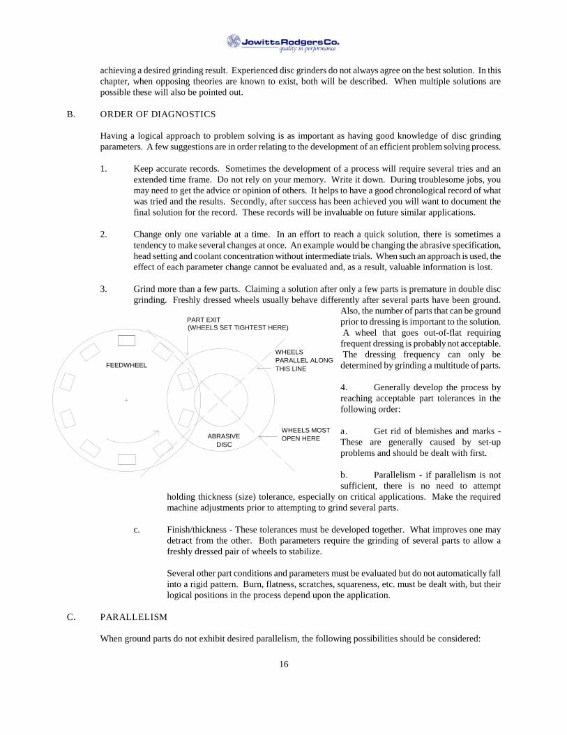
PART EXIT(WHEELS SET TIGHTEST HERE)
WHEELSPARALLEL ALONGTHIS LINE
WHEELS MOSTOPEN HERE
FEEDWHEEL
ABRASIVEDISC

6
Fashion the indicator so that when it is at the 12 o=clockreading, or at the top of the wheel, the indicator faciesdown and can be read with a mirror. When the wheel isrotated 180and is at the 6 o=clock position, the indicatorcan be read easily.
3. Beginning with the left (#1) wheel, indicate to the straightedge at 3 o=clock and 9 o=clock and again at 6 o=clock and12 o=clock. Adjust the position of the #1 head until theindicator reads zero all the way around. This will be calledthe zero setting for this head.
4. Remove the straight edge from the rotary hub and align theright head to the left head, obtaining again a 0 reading at alltimes.
5. Align the dresser. Remove the indicator from thesteel disc wheel and mount an indicator to the head of thedresser arm near the point of the diamond. Then indicatethe dresser to the left head and align the dresser arm sothat it reads within .0005" across the face of the steel discwheel.
6. Put in the head settings for grinding. A typicalsetting for part entry at bottom is shown at left.
III. THROUGH FEED DISC GRINDERS
A. GENERAL CONSIDERATIONS
A double disc grinder of the through feed type can have any one of many different parts feeding mechanisms. Theseinclude but are not limited to a belt feeder, a roll feeder, a chain feeder, a magnetic disc feeder and a short stroke pusherfeeder. Each mechanism pushes a stream of parts through the grind zone, between upper and lower guide bars, with onepart pushing another. With each type of mechanism having distinct advantages and disadvantages, the belt feeder is themost popular by far, and will be the basis for discussion in this chapter. Set-ups are fundamentally the same for all ofthese mechanisms.
0
0
Disc Wheel Dresser Arm
LeftHead
(front view)
0
0
(top view)
Dresser Arm
LeftHead
(front view)
(top view)
Exit
(tight at top)
Exit(tight at front)

7
In general, the through feed double disc grinder is well suited for high production needs when parts have relatively lightstock, generally less than .020", and suitable shapes. Parts must be shaped such that they will not wedge in the grind zonewhen being pushed end to end in a stream. Round parts, having diameters of more than twice their length or width areparticularly suited to through feed grinding. Spinning action can be influenced to some extent on a round parts bychanging wheel direction, relative spindle speeds, etc. Mild spinning of the part wile passing through the grind zoneoften improves flatness and parallelism. Round parts are generally ground with head settings of .001" to .001" tight infront in a pure shear mode.
Rectangular and other non-round parts are also often ground on through feed machines. Of course, such parts cannot spinwhile being ground and normally will not exhibit the precise flatness and parallel tolerances of round parts. Head settingsfor these parts typically result in shearing 75% of the stock as the part enters, with the remaining 25% being removedprogressively as the part passes through the grind zone.
Very general limits on part diameter compared to machine size are tabulated below. However, historical or test datashould be considered as well, depending upon the required part tolerances.
Abrasive Diameter Max. Part O.D.
23 430 1036 2042 24
The thinnest parts generally ground are about .060", and guide bar tensioners are usually necessary when guide bars areless than .125" thick. Wheels are usually run opposed on through feed machines to minimize forces and wear on tooling.Abrasives turning in the same direction would instantly destroy the guide bars.
If squareness must be generated in a disc grinding operation, the through feed method is almost never suitable, and therotary or oscillator method should be considered. However, if squareness already exists, through feed grinding willgenerally not degrade the parts as long as stock removal is light.
Several advantages exist over other types of parts feeding.
1. Production rates are generally high.
2. Loading and unloading is relatively simple.
3. Through feed machines are the most flexible for changing over for a variety of parts. Guide barspacing must be adjusted for different part heights. For thickness changes, the entrance and exit guidesmust be re-set and the guide bars re-centered. Oftentimes the guide bars do not have to be changedunless part thicknesses vary dramatically.
The center of a through feed machine is also the left hand (#1) grind line. When part thicknesschanges, only the right hand (#2) grind line changes. As a result, the left hand entrance and exit guidesare "fixed" and normally do not require repositioning.
4. Head alignments are simplified since the abrasives are generally parallel in the vertical direction andare rarely changed. Adjustments are only necessary front to rear.
5. Dressing of abrasives is for all practical purposes not compromised with varying head settings, sincetop to bottom settings are always zero-zero (parallel). Dressing will generate very close to flat wheelfaces.

8
Some disadvantages of through feeding must also be recognized:
1. Some non-round parts may experience better quality on a rotary feed if spinning is advantageous.
2. The grind zone must be cleared manually prior to dressing. This is usually done by feeding a plasticbar (thinner than the parts) through the grind zone pushing the last parts out. For this reason, throughfeeds are less suitable for flexible systems and require continuous parts feeding (no stoppages or lackof parts to the machine).
3. Thickness control has some limitations, whether automatic or manual, due to a delay between grindingand gaging. This limitation is severe when abrasive usage per piece is high or erratic.
Any back pressure on the parts stream exiting the grind zone is usually objectionable, because part quality (tolerances orcosmetic) can be altered. Even the slight force necessary to push parts through a machine mounted post process gage cancause sever problems. To prevent back pressure, a powdered exit device is desirable. This usually consists of an exitroller that provides sufficient force for any downstream process, such as gaging. The exit roll usually is set-up to moveparts slightly faster than the through feed device at the front of the machine. Often, a slight incline of the entire partsflow/feed system is sufficient to prevent the delay between grinding and gaging. However, it does not absolutely preventback pressure. Wile inclined systems have advantages, they also introduce compound head settings for abrasivealignment.
B. MISCELLANEOUS INFORMATION ON THROUGH FEED MACHINES
It is a common practice to design through feed machines so that the center of the part rides approximately 5/8" above thecenter of the abrasive. In the case of small parts, it is wise to check how the part goes across the typical 1" diametercenter hole of the abrasive. On parts that are very thin and small it is not wise to have radial slots in the abrasive as theparts can get caught near the center hole.
In designing abrasives for throughfeed machines, the ultimate abrasive has the best dress life, as dressing on athroughfeed machine is particularly cumbersome. Parts that are round usually require two and sometimes three gradezones of abrasive, with the center grades being softer. On parts that are rectangular, a single grade wheel is used.
C. ALIGNMENT AND SET-UP PROCEDURES
Proper alignments of all machine components that touch or influence the part during grinding are absolutely critical to thesuccess of double disc grinding. The following procedures should be used to prepare a through feed machine forgrinding.
1. The left hand entrance guide should be the reference surface to line up the left hand head. Clamp along straight edge** against the left hand entrance guide, straight through the grinding wheels.**Note: An accurate steel straight edge approximately 48" in length will normally prove adequate to
align disc grinders using 30" diameter abrasives or smaller. The straight edge should bestraight within .002" for total length. For extremely precision tolerances, a straightness of.0005" is desired. The straight edge must have sufficient rigidity. A steel straight edgeapproximately 48" long x 1" wide and 1/4" thick will provide the necessary stiffness.
2. Mount the steel disc wheels to the spindle wheel collar without abrasives, and attach a dial indicator tothe left(#1) disc wheel by bolting through a hole in the outer bolt circle. (Disc wheels must bemounted during this procedure, because their weight will alter alignment of the machine).
9
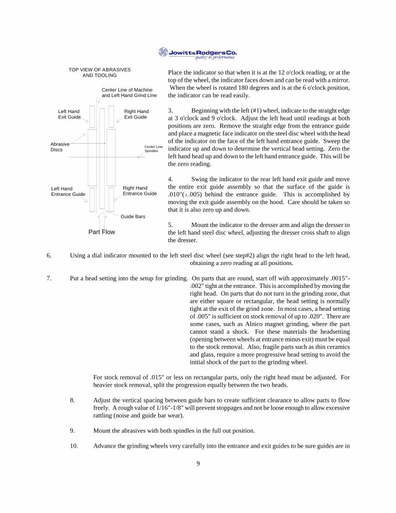
Place the indicator so that when it is at the 12 o'clock reading, or at thetop of the wheel, the indicator faces down and can be read with a mirror.When the wheel is rotated 180 degrees and is at the 6 o'clock position,
the indicator can be read easily.
3. Beginning with the left (#1) wheel, indicate to the straight edgeat 3 o'clock and 9 o'clock. Adjust the left head until readings at bothpositions are zero. Remove the straight edge from the entrance guideand place a magnetic face indicator on the steel disc wheel with the headof the indicator on the face of the left hand entrance guide. Sweep theindicator up and down to determine the vertical head setting. Zero theleft hand head up and down to the left hand entrance guide. This will bethe zero reading.
4. Swing the indicator to the rear left hand exit guide and movethe entire exit guide assembly so that the surface of the guide is.010"(.005) behind the entrance guide. This is accomplished bymoving the exit guide assembly on the hood. Care should be taken sothat it is also zero up and down.
5. Mount the indicator to the dresser arm and align the dresser tothe left hand steel disc wheel, adjusting the dresser cross shaft to alignthe dresser.
6. Using a dial indicator mounted to the left steel disc wheel (see step#2) align the right head to the left head,obtaining a zero reading at all positions.
7. Put a head setting into the setup for grinding. On parts that are round, start off with approximately .0015"-.002" tight at the entrance. This is accomplished by moving theright head. On parts that do not turn in the grinding zone, thatare either square or rectangular, the head setting is normallytight at the exit of the grind zone. In most cases, a head settingof .005" is sufficient on stock removal of up to .020". There aresome cases, such as Alnico magnet grinding, where the partcannot stand a shock. For these materials the headsetting(opening between wheels at entrance minus exit) must be equalto the stock removal. Also, fragile parts such as thin ceramicsand glass, require a more progressive head setting to avoid theinitial shock of the part to the grinding wheel.
For stock removal of .015" or less on rectangular parts, only the right head must be adjusted. Forheavier stock removal, split the progression equally between the two heads.
8. Adjust the vertical spacing between guide bars to create sufficient clearance to allow parts to flowfreely. A rough value of 1/16"-1/8" will prevent stoppages and not be loose enough to allow excessiverattling (noise and guide bar wear).
9. Mount the abrasives with both spindles in the full out position.
10. Advance the grinding wheels very carefully into the entrance and exit guides to be sure guides are in
Center LineSpindles
Right HandEntrance Guide
Left HandEntrance Guide
Part Flow
Guide Bars
Right HandExit Guide
Left HandExit Guide
AbrasiveDiscs
Center Line of Machineand Left Hand Grind LIne
TOP VIEW OF ABRASIVESAND TOOLING
10
the proper location. There should be approximately 1/16" clearance between the outside diameter ofthe grinding wheel and the inside radius of the entrance and exit guides. Interference between theabrasives and the guides can damage the guides. If sufficient clearance does not exist, remove theguides and have the proper clearance ground into the piece. Do not attempt to grind the guide usingthe abrasive on the double disc grinder. The next set of abrasives or another head setting could causethe problem to resurface, probably severely damaging the guide plate.
11. The dresser on a throughfeed machine straddles the guide bars in the grind zone. The proper spacersshould be used in the dresser arm to allow the dresser assembly to clear the guide bars. The dresserarm should also be checked so that it is in the center of the hood so that when the grinding wheels areretracted for their dress position, there is still clearance to dress each wheel. When dressing, it isnormally recommended that .001" be removed from each wheel per pass. The dresser speed on a 30"machine should be approximately 50 seconds total. These are starting points and can be adjustedaccordingly. Should a finer finish be required after dress, a slow dress speed should be used. Themicrofinish on the part will always be higher immediately after dress.
12. After the wheels are dressed, they should be plugged up and down, front and back, to be sure there isno sag when the additional weight of the abrasive is added to each head assembly. If a minoradjustment should be in order, the right head is adjusted vertically to obtain a true plug condition, topand bottom. Perform this check each time new abrasives are installed to verify alignments.
13. Before grinding, coolant distribution should be monitored by checking the coolant flow with thespindle stopped. The coolant streams coming through the spindle should meet in the middle of thegrind zone. If there is a coolant line in front or entrance part of the grind zone, the coolant should bedirected to the point of original contact in the grind zone and should be directed at the center of the topof the guide bar.
Note: In the case of very thin parts, such as small piston rings and very light ceramic parts, toomuch coolant can influence the part piece in the grind zone, so a minimum amount of coolantshould be used. In the case of large, think work, such as valve plates, it will be necessary toput radial lines in the abrasives, or have coolant holes (manifolded coolant) through theabrasives. Thin work is the most difficult of all applications to have coolant at the point ofcontact in the grind zone.
14. The grinding wheels can now be set at their proper location for grinding. The left hand wheel is firstmoved in so that it is flush or in the same plane as its entrance guide. This is normally accomplishedby putting a piece of flat tool stock on the entrance guide and advancing the left wheel until it makescontact with the tool. Then advance the left hand wheel further to one half the stock removal plus onehalf the clearance between the entrance guides and the unground workpiece. This is in the case ofround parts, where the head setting is tight in the front.
In the case of rectangular parts, the head setting must be considered when establishing the entranceguide/left wheel set up procedure, depending upon the amount of head setting involved. In thiscalculation, the stock removal value is the amount to be sheared at the entrance, or
Stock Sheared = (Total stock)-(tight at exit head setting)
Bring the right hand entrance guide in to approximately .010" from the thickest part on rough grindingoperations, considering warpage, flashings, and various irregularities of a rough grind. On semi-finishand finish work, the right hand entrance guide should be brought to within .004" for a better setup.
The objective of entrance guide clearances and wheel locations is to present equal stock to bothgrinding wheels.

11
15. The right hand exit guide should be set sufficiently away from the grind zone so that it does notinterfere with the part coming out of the grind zone, but merely holds it on the exit guide bars. Theexit guides should never be used to steer the parts out of the grind zone. The grinding wheelsthemselves must be the only guiding influence as the part exits the grinding zone. It is recommendedthat the exit guide be set .010"(.005") behind the entrance guide.
Note: On throughfeed machines, particularly for long parts, the exit area of the grind zone must bekept clear of any part interference, such as coolant brushes, tight exit guides or gage fixturingthat would slow up the parts, as back pressure into the grind zone will cause swipe marks onthe parts. In the case of machine mounted post process gages, the gage should be of such adesign that there is no back pressure (such as double opposed air), or the machine shouldinclude a powered exit drive assembly to speed up the parts through the gage.
16. The right hand grinding wheel is now ready to be moved into place. A work piece is put between thegrinding wheels near the entrance on a round part and near the exit on a square part. The right wheelis brought in so that the wheel spacing is close to the finished thickness of the part. The part is thenpushed through the grinding zone with the grinding wheels running, hood closed, with a stick thinnerthan the work piece. Measure the thickness and adjust the right wheel only. Repeat this test untilproper thickness is achieved.
17. Once size is obtained, both wheels are brought in either simultaneously or alternately as the wheelswear to maintain size. In monitoring size on a throughfeed machine, consider that the parts are usuallybeing finished at the entrance of the grind zone and do not over react to infeeding. Wait for parts toclear through the grind zone after an infeed. It is of utmost importance on a throughfeed machine, thatthere is constant feeding of the parts through the grind zone. Should the flow of parts stop,eitherthrough a jam in the front, exit, or lack of parts, those parts in the grinding zone should not beconsidered a true representation of the quality of the grind.
In selecting an increment of feed, it is suggested that not more than 50% of the size tolerance be usedas an increment. For example, if the thickness tolerance is .0005", the maximum infeed increment thatshould be considered is .00025".
IV. ABRASIVES
A. GRAIN - The abrasive particles used in grinding are called grain. The materials used as grain have twoimportant properties. They are very hard and they have sharp edges. In order to be effective, the grain must beharder than the material being ground and must also be able to stay sharp during the grinding process. Thefriability of the grain therefore also is important. As the grain is used, its friability determines how quickly itfractures and forms new cutting edges. The more friable the grain, the more quickly it fractures and the sharperit stays and the more aggressively it will cut.
There are several materials that are widely used as abrasive grains:
12
! Diamond! Cubic Boron Nitride (CBN)
! Ceramic Aluminum Oxide (SG orCubitron)
! Silicon Carbide! Aluminum Oxide! Garnet
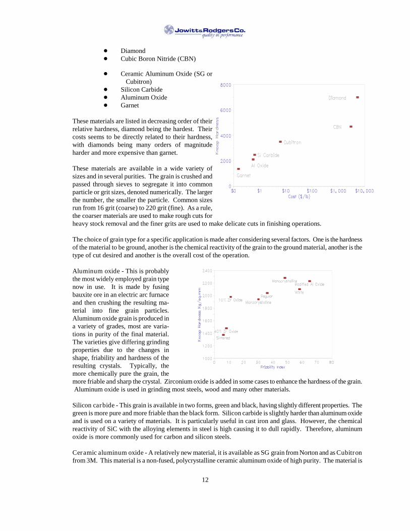
These materials are listed in decreasing order of theirrelative hardness, diamond being the hardest. Theircosts seems to be directly related to their hardness,with diamonds being many orders of magnitudeharder and more expensive than garnet.
These materials are available in a wide variety ofsizes and in several purities. The grain is crushed andpassed through sieves to segregate it into commonparticle or grit sizes, denoted numerically. The largerthe number, the smaller the particle. Common sizesrun from 16 grit (coarse) to 220 grit (fine). As a rule,the coarser materials are used to make rough cuts forheavy stock removal and the finer grits are used to make delicate cuts in finishing operations.
The choice of grain type for a specific application is made after considering several factors. One is the hardnessof the material to be ground, another is the chemical reactivity of the grain to the ground material, another is thetype of cut desired and another is the overall cost of the operation.
Aluminum oxide - This is probablythe most widely employed grain typenow in use. It is made by fusingbauxite ore in an electric arc furnaceand then crushing the resulting ma-terial into fine grain particles.Aluminum oxide grain is produced ina variety of grades, most are varia-tions in purity of the final material.The varieties give differing grindingproperties due to the changes inshape, friability and hardness of theresulting crystals. Typically, themore chemically pure the grain, themore friable and sharp the crystal. Zirconium oxide is added in some cases to enhance the hardness of the grain.Aluminum oxide is used in grinding most steels, wood and many other materials.
Silicon carbide - This grain is available in two forms, green and black, having slightly different properties. Thegreen is more pure and more friable than the black form. Silicon carbide is slightly harder than aluminum oxideand is used on a variety of materials. It is particularly useful in cast iron and glass. However, the chemicalreactivity of SiC with the alloying elements in steel is high causing it to dull rapidly. Therefore, aluminumoxide is more commonly used for carbon and silicon steels.
Ceramic aluminum oxide - A relatively new material, it is available as SG grain from Norton and as Cubitronfrom 3M. This material is a non-fused, polycrystalline ceramic aluminum oxide of high purity. The material is
13
a 'grown', solid crystal with a controlled shape. It is very hard and sharp but not very brittle. However, it is ableto keep its sharp edge much longer than conventional aluminum oxide. The grain has proven to be very usefulagainst hard steel alloys, such as tool steels.
CBN - Cubic boron nitride grain is in a class (along with diamond) known as super-abrasives. CBN is a veryhard synthetic material produced under extreme temperature and pressure. It can withstand temperatures >2500F, where as diamond oxidizes (burns) at only 1600F. This property makes CBN a potentially usefulmaterial for grinding steel. The limitation is its very high cost and its need for extremely rigid grindingequipment.
Diamond - Available in two forms, natural and man-made, this is the hardest material known to man. Diamondis a very commonly used grain, despite its very high cost, for a wide variety of applications. Though not usefulin grinding most steels, it is the abrasive of choice for glass and ceramics. It is also used to grind concrete,carbide tool steels, and polish gems.
Garnet - A natural gem like material, garnet is used principally in wood finishing. It is softer than aluminumoxide, so it is used sparingly for metal finishing.
J&R Specific Grains - We currently have eight specific types of grain available to incorporate in our products - variousforms of aluminum oxide, silicon carbide and cubitron. Each of the grains behave differently and are used either alone orin combination with others to meet specific needs.
Aluminum oxides
G - This is a form of brown aluminum oxide that is blocky and not exceptionally friable. Due toits shape and lack of friability, it is a hard acting grain, good for general purpose grinding ofsoft steels. It also is often used in combination with more friable grains to add additional lifeto the wheel. It is a relatively inexpensive grain.
A - This is a more friable version of G grain. It is still an inexpensive brown aluminum oxide,but is a little sharper and more friable. It is used on slightly harder materials than G and incombination with other grains on hard steels.
W - A white aluminum oxide, this is a very aggressive grain. It is sharper, harder and more brittlethan the brown grains. This is an expensive grain that works well on hard steels such as toolsteels and stainless steel. It often is used in combination with either G or A to offset the cost.
F - An even more friable form of white aluminum oxide. It is the sharpest, most aggressive ofthe aluminum oxides that we have available. F is used where W is not aggressive enough,and is often used in combination with other grains to offset the cost.
Silicon Carbide
X - This is our standard silicon carbide grain. Silicon carbide is a hard, brittle grain, more sothan aluminum oxide. It is most commonly used on non-steel materials, such as cast iron andaluminum. It does not work well on steel because it is chemically reactive with the carbon insteel.
C - A more pure form of silicon carbide, it is slightly more friable than X. This grain is not useda great deal.
Ceramic grains
R - A ceramic coated brown aluminum oxide, this grain forms stronger bonds with our resin. It
14
is used to make very hard wheels.
Q - Our newest grain is Cubitron made by 3M and is very similar to SG from Norton. Thisgrain is a polycrstalline ceramic aluminum oxide that is extremely hard, sharp and veryfriable. It retains its sharpness for an extensive period, giving good wheel life and improvedthrough put. A very aggressive grain, it is used for hard steels in combination with whitealuminum oxide grain.
B. GRITS - All of the grains discussed are available in a range of sizes, called grits. They are classified by themedium sieve size that the particles pass through. A 6 grit grain is very coarse and a 600 grit grain is extremelyfine. For normal metal working applications, grits from 16 to 180 are used. The coarser grits take heavy cutsand remove large amounts of material whereas the finer grits take a delicate cut and are generally used forfinishing.
C. BOND TYPES - As J&R sells bonded abrasives, we are very much concerned with the material used to holdthe abrasive grain together, called bonds. The bond glues the grain particles together, holding them to do theirwork. At some point in the grinding process, it is beneficial for the bond to release the grain on the workingsurface of the grinding wheel to expose unused, sharp grain. In an optimal situation, this happens when thegrain at the surface becomes dull and no longer is cutting efficiently. The amount of bond used to hold thewheel together is varied to modify when this occurs. The relative effort required to free grain particles from thewheel surface is commonly referred to as the hardness of the wheel. Wheels that release grain easily arereferred to as 'soft', and wheels that require a lot of effort to free the grain are called 'hard'. Typically, harderwheels are used on softer materials, as the grain takes longer to dull, and soft wheels are used for hard materialsas the grain dulls much more rapidly.
Many different materials have been and are still being used as bonds. Some of them are:
Vitrified - This is probably the most commonly used bond. It is a glass-like material that is fusedtogether under high temperatures. The abrasive and bonding materials are first mixed together andthen pressed together in a mold under high pressure. The wheel is then fired in a kiln for as long asseveral days, reaching temperatures as high as 2300F. Vitrified bonds are strong, though somewhatbrittle. It is its brittleness that causes it to break down during the grinding process.
Resin - This is a bond type that is distinguished for its high strength, resiliency and cool cuttingcharacteristics. The resins used are synthetic phenol/formaldehyde polymers that set at moderatetemperatures. Resin bonded abrasives are typically baked in ovens rather than fired in kilns. Resinbond's high strength makes it the bond of choice for discs and foundry wheels, and its resiliency andcool cutting properties make it useful for many surface grinding applications. It is less appropriate forcrush or form grinding, however, as it has difficulty in holding sharp edges or contours on the grindingface.
Epoxy - This is a relatively new bonding material. It has similar properties to resin bonds, though witha bit more resiliency and cool cutting properties. Its principal drawback has been the difficulty induplicating its performance characteristics from wheel to wheel.
Magnesite - This a relatively old bonding technology that is now used mainly for dry grindingapplications. The bond is made from a mixture of magnesium oxide and magnesium chloride to form acold setting cement. The bond, which takes many weeks to completely set, is also referred to asOxychloride. Magnesite is not well suited for use with coolants, as it tends to mix with the coolantand solidify in the coolant lines on the grinding machine. Due to its cool cutting characteristics, it ismost commonly used in dry grinding applications such as spring and some cutlery grinding.

15
Metallic - Metal bonds are used mostly for super-abrasive wheels. These are mixtures of variouspowdered metals that are pressed to hold diamond or CBN abrasive grain.
Other - There are many other bonding materials used, though most are used sparingly or only for veryspecial applications. These include shellac, rubber and silicate bonds, among others.
J&R Bond Varieties
Jowitt & Rodgers manufactures only resin and epoxy bonded products. Our resin is a liquid thermosettingphenol/formaldehyde resin. This resin is unique to J&R, first developed and still manufactured by Geo. Jowitt& Sons in England. A unique feature of the resin is that it is liquid at room temperature, while most other resinsare powders. Being liquid offers some mixing advantages:
! better homogeneity of the grain/bond mixture! can be hand tamped for more consistent density! bakes quickly (overnight)! bakes at a low temperature.
The bond itself is very stable under most grinding conditions. However, the linkage it forms with the grain isaffected by high heat and pH. At high coolant temperatures and caustic pH levels, the junction between theresin and the grain breaks down over time and the wheel will act softer. This phenomena is accelerated rapidlyas temperature and/or pH is increased. Care should be taken to maintain the coolant temperature to as near toroom temperature as possible and the pH to 9 or lower.
We employ an additive to reduce this effect, but it does not eliminate it. If the customer can not control thecoolant conditions, two steps can be taken to retard the effect. First is to remove the coolant from the wheel if itis to sit for a prolonged period, say over a weekend or removed from the machine. This can be done by 'spindrying' the wheel (running without the coolant flow on). Also, the phenomena is lesser on larger grain sizes, sospec the wheel with absolutely the largest grit possible for the job.
V. DIAGNOSTICS
A. OVERVIEW - Double Disc grinding is generally a high production, highly accurate method of producing dualflat and parallel surfaces simultaneously. While the process can be extremely cost effective because of its speedand precision, success can only be achieved when several set-up parameters are correct. Once the proper set-uphas been achieved, the correct abrasive has been installed, and everything should be ready, problems holdinggrinding tolerances may still exist. When problems occur, whether during initial development of the process orin the midst of production, it is beneficial to have a thorough understanding of variables that impact discgrinding. That is the objective of this chapter, i.e., to document these variables and their impact on grindingresults.
Subsequent paragraphs first address how to go about developing a process in general (the order of things),followed by a discussion of each basic type of tolerance problem that may be encountered in disc grinding.Finally, a diagnostic summary table is presented which suggests possible solutions to investigate for each typeof problem encountered. This table is brief but refers back to paragraphs which discuss the subject in depth.
Disc grinding is not a black art. There is no magic. There are, however, proven methods of correctingproblems that this chapter be studied and understood in detail. Not every problem that may show up isdiscussed in this chapter, but having a sound knowledge of these basics will help you reach solutions to otherproblems.
One last thing to note before getting into the details of diagnostics. Often there is more than one way of
16
achieving a desired grinding result. Experienced disc grinders do not always agree on the best solution. In thischapter, when opposing theories are known to exist, both will be described. When multiple solutions arepossible these will also be pointed out.
B. ORDER OF DIAGNOSTICS
Having a logical approach to problem solving is as important as having good knowledge of disc grindingparameters. A few suggestions are in order relating to the development of an efficient problem solving process.
1. Keep accurate records. Sometimes the development of a process will require several tries and anextended time frame. Do not rely on your memory. Write it down. During troublesome jobs, youmay need to get the advice or opinion of others. It helps to have a good chronological record of whatwas tried and the results. Secondly, after success has been achieved you will want to document thefinal solution for the record. These records will be invaluable on future similar applications.
2. Change only one variable at a time. In an effort to reach a quick solution, there is sometimes atendency to make several changes at once. An example would be changing the abrasive specification,head setting and coolant concentration without intermediate trials. When such an approach is used, theeffect of each parameter change cannot be evaluated and, as a result, valuable information is lost.
3. Grind more than a few parts. Claiming a solution after only a few parts is premature in double discgrinding. Freshly dressed wheels usually behave differently after several parts have been ground.
Also, the number of parts that can be groundprior to dressing is important to the solution.A wheel that goes out-of-flat requiring
frequent dressing is probably not acceptable.The dressing frequency can only be
determined by grinding a multitude of parts.
4. Generally develop the process byreaching acceptable part tolerances in thefollowing order:
a. Get rid of blemishes and marks -These are generally caused by set-upproblems and should be dealt with first.
b. Parallelism - if parallelism is notsufficient, there is no need to attempt
holding thickness (size) tolerance, especially on critical applications. Make the requiredmachine adjustments prior to attempting to grind several parts.
c. Finish/thickness - These tolerances must be developed together. What improves one maydetract from the other. Both parameters require the grinding of several parts to allow afreshly dressed pair of wheels to stabilize.
Several other part conditions and parameters must be evaluated but do not automatically fallinto a rigid pattern. Burn, flatness, scratches, squareness, etc. must be dealt with, but theirlogical positions in the process depend upon the application.
C. PARALLELISM
When ground parts do not exhibit desired parallelism, the following possibilities should be considered:
PART EXIT(WHEELS SET TIGHTEST HERE)
WHEELSPARALLEL ALONGTHIS LINE
WHEELS MOSTOPEN HERE
FEEDWHEEL
ABRASIVEDISC

17
1. For a rotary feed grinder the wheels are generally tightest at point of exit from the grinding zone. Freshlydressed wheels should be parallelalong a line running from 90 above the exit point to 90 belowthe exit point. Plug the abrasive atthese two points to ensure a propersetting.
Check for wheels glazing. A dull wheel can result from many things. In each case, a wheel that is not cuttingfreely will build up grinding pressure resulting in machine deflection.
Wheels that are dull may be glazed because they are too hard and are not breaking down uniformly,preventing the exposure of new sharp grains. A switch in abrasive specification to a softer grade or amore friable grain may be necessary to keep the wheel constantly sharp. Erratic surface finish will alsoindicate that the wheel is undergoing a "glazing, breaking, glazing, breaking" cycle.
Improper dressing may cause a wheel to glaze. Wheels that are dressed tight will generally remaintight. Wheels that are dressed open will generally remain that way during grinding. To open up awheel or dress it sharper, use single point diamond or dresser cutters.1 Speeding up the dresser tocreate a record groove effect will also generate a more open wheel.
An effect similar to glazing would be wheel loading where grinding particles cling to the wheel orembed in the bond. This reduces chip clearance and dulls the wheel. The solution may be a softerwheel grade or a different type of abrasive grain material.
Dirty coolant that carries swarf and impurities into the grinding wheel, clogging open areas used tocarry coolant and chips, is another culprit that can cause dulling action. Adequate filtration must beprovided. Check the coolant concentration. It should have a pH in the range of 7-9. Thick coolantcan cause loading.
3. Parts not spinning while grinding. Spinning improves parallelism. Round parts that are spinning whilebeing ground exhibit a random cross hatched finish. Grind marks on the part that are parallel indicatethat spinning is being restricted. Spinning can be achieved by running one wheel slightly faster thanthe other when they are rotating opposed.
Abrasives rotating together will create the most violent spinning action of all and should be generallyavoided. Noise, high tooling wear, as well as cosmetic blemishes may result from a violent spinningaction.
Clearances between parts and tooling may be insufficient, restricting free spinning.
4. Abrasives out-of-flat. When abrasives reach a certain level of out-of-flatness, poor tolerances,including parallelism, result. It signals the need to dress the wheel flat. When parallelism deterioratesover the life of a dress, it is an indication that abrasive shape is the cause.
If dressing is required too frequently, measures to keep the wheel flat, such as zoning, should beconsidered.
1There are negatives associated with a single point diamonds and dresser cutters. Although they can producesharper wheels, their wear rate is higher, especially for cutters.

18
Improper set-up can also cause wheels to go out of shape prematurely. Stock removal that is not splitequally between the abrasives can cause mis-shaped wheels. Proper set-up can correct this.
5. Pinch-off. This condition can occur on rotaries or through feeds when wheels are tight at exit (progressivegrinding) and grinding pressure is high.
During grinding the wheels spring apart due to grinding pressure. As the part exits, the wheels spring backtogether creating "pinch-off".
This condition will exhibit parallelism over most of the part, with a taper at the trailing edge. The condition isworsened if the trailing portion of the part is narrow. Feeding the parts in a direction to avoid a smaller area atthe trailing edge is preferred. Pinch-off can also be reduced by altering abrasive specifications to reducepressure.Pinch-off can also occur, particularly on a rotary, if a part is entering the wheels just as another part is exiting.As the unground part enters between the wheels, the abrasives will be spread apart slightly. Not only will thesteel backing plates (disc wheels) deflect, but the spindle will also bend. The bending of the spindle will cause a"closing" of the abrasives at the exit point. This condition must be avoided by proper tooling design.
6. Steps. A step, as opposed to a taper, consists of a sudden low area at the loading or trailing edge of thepart. This condition is caused by hesitation of the part at either the entrance or exit of the grindingzone. Check for erratic feeding or interferences near the exit area preventing free exit of the part.
7. Coolant temperature is excessive. It is generally recommended that coolant temperatures never exceed15F above ambient. Coolant through the spindles will remove heat generated by the bearings if thecoolant temperature is controlled. Failure to remove bearing heat will cause head distortion, affectingthe top-to-bottom setting, and as a result, parallelism.
D. FLATNESS
Many of the reasons why parts do not exhibit good flatness are the same as for poorparallelism. In general pinch-off, step, spinning action, and out-of-flat or dull abrasivesdiscussed earlier pertain equally to flatness tolerances as they do to parallelism. Inaddition, there are several other reasons why parts may be out-of-flat.
1. Excessive stock. This condition can cause heavy grinding pressures and, as aresult, deflection. Deflection of grinding wheels or workpieces can impact flatness.
Excessive stock can also generate heat which causes distortion during grinding, resultingin non-flat parts after cooling. Take more grinding passes.
2. Incoming parts are out-of-flat. Parts that are distorted coming to the grinder willtend to distort to a semi-flat shape during grinding. Even though the part may be groundto a good parallel condition, it will exhibit a curved shape after grinding. Even generate aflat ground part when incoming stock is excessively warped.
To correct this situation, the incoming part shape must be improved, or another grinding pass may beadded to pre-condition the parts prior to a finish grind.
A slower feed rate may also improve the resulting flatness, because grinding pressure is reduced.
3. Excessive coolant temperature. If coolant temperature is more than 15F above ambient, the effect onpart flatness can be damaging. Any workpiece at ambient temperature, when exposed to hot coolant,
AbrasiveDisc
Feed WheelRotation
Improper
AbrasiveDisc
Feed WheelRotation
Prefered to MinimizePinch

19
could have a tendency to "curl" during the grinding process. If a thermally distorted workpiece isground flat, it will return to a non-flat condition after cooling.
4. Poor coolant delivery. Coolant must be presented to the workpiece/ wheel interface in order toadequately remove the head generated during grinding. Inadequate coolant causes the workpiece toheat up. When a part heats up excessively, but perhaps not uniformly due to the quickness of grinding,may not be flat after it cools.
Parts that exit the grinder warm indicate improper or inadequate coolant delivery. Increase coolantflow and/or redirect coolant to more effectively cool the part/wheel interface.
5. Incorrect abrasive specification. The wrong abrasive can cause distortion of the part during grindingdue to excessive pressure. An abrasive that is dull or loaded will rub instead of cut and will generateheat, Heat, particularly if not generated uniformly on both sides, will cause the part to want to distortduring the grind. After grinding, the part will not be flat.
Corrective action is an abrasive specification that remains consistently sharp.
6. Incorrect coolant type. For materials that are particularly heat sensitive it may be advisable to use asoluble oil coolant that increases lubricity between the wheel and the part. Lubricity generally reducespower required to grind and also reduces the heat generated in grinding. Reduced heat generation willaid in obtaining flatness.
E. FINISH
Finish on a workpiece is a measure of the roughness of a machined or ground surface. Usually measured with aprofilometer, at least two methods of calculating a finish "value" exist. One method is RMS (Root MeanSquare) and the other is Ra (Arithmetic Average). Each method uses the distance between "peaks" and"valleys" as a basis for the calculation. If the finish is fairly uniform, the values calculated by each method willbe approximately equal. However, if the distances between peaks and valleys vary considerably, the RMS valuewill be higher. Basically, the Ra value is more generally accepted today, as RMS lost popularity back in the1950's.
Finish on a workpiece can either be too rough or too fine. In many cases, a finer than required finish isacceptable, but there are exceptions. A finish that is too good may not be advisable for the application, becausethis ability to hold good thickness tolerances and to remove heavy stock is compromised when abrasivespecifications are primarily designed to achieve finish. The most accepted method of controlling finish on theworkpiece is through the choice of grit size. With all other things equal, abrasives with a smaller grit size willact softer than those with large grains. However, depth of cut (stock) is limited by the length of abrasive grainextending from the bond.
Finish Too Rough
Poor finish or finish that is too rough can have many causes/solutions.
1. Grit size may be too large. Try a smaller grit, but abrasives may need to be of a harder grade, andstock on the finishing pass may have to be reduced.
2. Coolant may be dirty. Clean the tank and check the filter.
3. Coolant may be too strong. Check the concentration and dilute if necessary. Maintain a pH of 7 - 9 toprevent premature breakdown of the resinoid bond.

20
4. The abrasive may be overworked by excessive stock or a feed rate that is too high. Excessive"shelling" away of the grain will cause a rough finish.
5. Machine Vibration. Vibrations caused by sources such as bearing failure, improperly mountedabrasives, out-of-balance abrasives, motors, nearby machinery, etc., can cause poor surface finish. Thesource should be isolated and corrected. If environmental vibrations are the culprit, the machineshould be isolated from its surroundings. (Consult machine manufacturer concerning recommendedmethod of isolation). If coolant is permitted to flow on stationary abrasives, an out-of-balancecondition is caused when the coolant is absorbed in one area. It is good practice to let the spindles runwith the coolant flow shut off to permit the coolant to be thrown off, avoiding an out-of-balancecondition. DO NOT EXCEED 5 MINUTES DRY RUNNING. ROTARY UNION SEAL DAMAGEMAY RESULT.
6. Time of contact between part and abrasives may be too short. Increased time on the abrasive through aslower feed rate, a "tight at exit" head setting, or other means may help achieve a finer finish.
7. Abrasives may be too soft, resulting in an excessive breakdown rate. If this condition exists, it wouldalso be evident when trying to maintain the thickness tolerance. Consider a new abrasive specification.
8. Dressing rate or depth of cut may be excessive. A slower dressing pass will achieve a smoother wheeland finer finish. A lighter cut on the finishing dress pass will also result in a smoother abrasive face.The use of diamond clusters will allow faster will allow faster dressing cycle than single points andstill maintain a smooth dress.
9. Insufficient coolant delivery to the grinding zone. If the grind zone is starved for coolant, an increasedabrasive breakdown rate may occur, resulting in a poor finish. Increase coolant to the grinding zone.
10. A hard abrasive can cause dresser vibration and a rough dress. To correct this condition, reduce depthof cut, speed of dress, and switch to diamond clusters.
11. Imbedded foreign matter in tooling or abrasive bond can cause scratching that will result in locallypoor finish.
12. For large solid areas of contact on piece parts, a considerable amount of loose abrasive can degradethe finish, particularly when shear grinding is involved. Getting the parts out from between theabrasives quickly after grinding is complete can reduce the exposure to loose grains and improvefinish. Flushing away the loose grain with a high volume of coolant also will improve surface finish.For thin work having a solid face, manifolding the coolant through holes in the abrasive will aid influshing away loose grain.
13. An oil based coolant may be helpful if all other tolerances are being achieved. This type of coolantunder light stock removal promotes a "rubbing" or "polishing" action, thereby improving finish.
Remember that after a fresh dress the finish will initially be rougher than after several parts have been ground.Let the abrasives "settle down" prior to evaluating the surface finish.
Finish Too Smooth
Finish that is too good or too smooth can be detrimental and may have a variety of causes.
1. The abrasive grain may be too small, if surface finish is consistent over time. Increase the grit size, butconsider going slightly softer with the grade if all other parameters are being satisfactorily met.

21
2. The wheels may be dull. Parts may be polished or burnished indicating that the abrasives are"rubbing" instead of cutting freely. A tell-tale size of this condition is a cycle of "rough-smooth-rough" parts, indicating that the wheels are not cutting consistently. Try working the abrasives harderby increasing the feed rate or the stock removal. This will induce faster wheel breakdown and maykeep the abrasives cutting consistently at an acceptable surface finish.
Increasing the speed of dressing will open the wheel up more, causing it to cut more freely. Generally,wheels that are dressed open will tend to stay open.
Dressing with a single point diamond or cutters will also result in a sharper wheel. Dressing tools mustbe sharp to be effective. Replace dull dressing tools.
The grade of the wheel may be too hard. A softer grade or a more friable abrasive grain may achieve amore consistent cutting action.
3. The abrasive may be loaded. Dirty coolant can contaminate abrasives, plugging up spaces for chipclearance and causing wheels to glaze.
Increase coolant flow to flush abrasives. Insure that coolant is being properly introduced to thegrinding zone.
Again, the abrasive specifications could be changed to a softer grade. Increased breakdown canprevent wheel loading.
F. SCRATCHES
Scratches on a ground surface are undesirable marks superimposed on the underlying finish. They may beisolated to one local area on the part, or they may be so dense that the scratches change the appearance of finishaltogether. Here are some potential causes of scratching.
1. The coolant may be dirty. Loose abrasive grit or other foreign particles may be contaminating thecoolant due to inadequate filtration. Trying to finish grind without a thorough cleaning following aroughing operation is just one example of such a condition. If this happens, clean the coolant tank andprovide adequate filtration.
2. Perforations in the disc may be clogged with grit and grinding swarf. Switching to a plain facedabrasive may be necessary.
3. The abrasive may have been contaminated with large grains or foreign material by the manufacturer.
4. Dislodged burrs, slag, etc., from the workpiece itself may come loose during the grind and be carriedacross the face of the part. When such action is suspected, clean a few parts and check the results.Preconditioning of parts may be required in severe cases.
5. Voids in the workpieces being ground may contain contaminants. If this is suspected, again, cleansome parts and monitor results.
6. Abrasive grains that shell away during grinding and are rubbed or rolled across the face of the part cancause scratching. A large volume of coolant directed to the grinding zone will help flush these loosegrains away from the wheel face before they can cause damage. Insufficient coolant flow canaggravate this condition, because excessive wheel breakdown is induced, creating even more loosegrain. A rough dress can also create a condition of excessive wheel breakdown.

22
7. When grinding in a shear mode if is often beneficial to remove the parts quickly from between thewheels after grinding is complete. This is particularly truce on large diameter full faced parts. Aninclined feed system on a through feed machine may improve results. The use of air or coolant tocreate an exit force may work equally well.
8. Exit guides may contain embedded foreign material or protrusions. Exit guides should bereconditioned if necessary.
9. A post process gauge may scratch a soft part if contact pressure is high. Pressure against the part bythe gauge finder may need to be reduced. Changing the contact material of the probe may alsoeliminate scratching.
G. BURN
Burn results from temperatures generated in a workpiece of sufficient magnitude to cause metallurgical changesin the material. Burn is not necessarily visual, but severe burn can be easily detected. Non-visual burn can bedetected by acid etch (Nitol) or by non-destructive checks for surface cracks, such as magnaflux or dyepenetrant testing.In diagnosing the cause of burn, one must take note as to whether it is only periodic or is on every part.
Burns on every piece
When burn exists on every piece, the cause may be:
1. Coolant too hot. Increase cooling capacity by adding capacity (gallons and surface area) or a heatexchanger of some type. Warm coolant will cause the parts to get warmer during the grind.
2. Coolant delivery to the grind zone may be insufficient. If the surface finish in the burned area looksnormal (not polished or burnished), the problem may be lack of coolant to the grind zone. Check thepump lines and delivery of coolant.
3. Excessive feed rate or stock removal can cause power losses into the workpiece in the form of heat.The rate at which heat energy is generated at the surface of the workpiece can be reduced by takinglighter stock or slowing down the feed rate. The surface temperature at the workpiece will be reduced,avoiding burn.
4. The abrasive may be dull or loaded, creating a rubbing action instead of efficient cutting. Rubbinggenerates heat. Analyze the burned area. If this area is polished or burnished, a dull abrasive is thecause. The solution is to try a softer wheel grade to achieve faster abrasive breakdown and a wheelthat stay sharp. The wheel can be made to act softer by slowing it down if a softer grade is not readilyavailable. Burn due to dull abrasives usually will coincide with inability to maintain thicknesstolerances. Dull abrasives increase grinding pressures and create added machine deflection. Erraticabrasive usage will result. Check the diamonds for sharpness. A single point diamond or dressercutter will produce a sharper wheel than cluster diamonds or rolls. A faster dressing pass will alsoimprove wheel sharpness.
5. Head settings may be improper. If a progressive head setting is being used, a pure shear setting mayreduce burn, depending on the material. Reduced time that a part is in contact with the wheel, due to ashorter grind path, may prevent burns.
If a shear setting is used and burn is evident, changing to shear plus progression will reduce the"shock" of removing all stock at the entrance point. Burn may disappear or be removed during theprogressive portion of the grind if not too deep.

23
On many applications, parts may burn following a fresh dress until a lead-in is developed on theabrasives. Once the lead-in is developed, the shock of heavy stock removal at the entrance is reduced.Leaving a lead-in after dressing or inducing a lead has been shown to eliminate burn on initial parts in
many cases. A lead-in can be introduced either manually or automatically, depending upon machinefeatures, in either a "taper" or "step" form.
Periodic burn
When burn is only periodic, check for the following causes:
1. Variation in stock removal. An occasional part with heavy stock can cause burn. More passes may berequired to reduce the maximum stock removal on any part.
2. Feed may be erratic. Occasional hesitation of parts in the grindzone may create enough additional heat to cause burn. Adjust the feedmechanism.
3. Coolant flow may fluctuate. Check the coolant system forrestrictions and eliminate the cause
H. BLEMISHES AND MARKS
Objectionable marks on ground surfaces appear in several forms and maybe measurable or just visual. Each form of blemish has distinct possiblecauses which are listed below. Most are a result of an improper set-up thatmust be corrected prior to continuing.
Discussion of blemishes is organized by general type and cause. Two terms are defined for purposes ofdiscussion. These terms are "dubs" and "swipes".
1. A "dub" is an arbitrary choice of terms for a general type of blemish usually caused by a problem at theENTRANCE to the grind zone. Some chief causes are outlined below.
a. Entrance guides out of alignment with abrasives. These guide plates are designed to directthe work piece between the abrasives. If the guide presents the part at an angle, dubs willresult.
b. Too much clearance between entrance guides and the part. Excessive clearance prevents the guides fromadequately controlling direction of the part. Recommendationsfor clearances are .010" for rough operations and .004" forfinishing.
c. Burrs or nicks on entrance guide. Any such protrusion will cause the part to enter the wheels misaligned.Remove and recondition the damaged surface.
d. Grind line has drifted off center in relation to the entrance guides. Abrasives should extend equal amountsbeyond their corresponding entrance guides. When drift occursdue to unequal abrasive wear, the part has to go "around thecorner". When the part hits one wheel harder than the other itwill bounce back toward the other abrasive at an angle. For arectangular part, one leading corner will dig into its abrasivecausing a dub mark while the other abrasive gouges the center of
GRINDING WHEELS
GUIDEGUIDE Part
Dub
FeedDirection

24
the opposing surface. For round parts that can spin, the dub maybe all along the edge of the part. We call this a "halo".
This condition can be corrected by shifting the grind line back toward the center of the twoguides. Infeed the abrasive on the side of the dub and outfeed the opposite one. An alternatemethod is to adjust grind line only by compensating for abrasive loss, infeeding only thewheel on the dubbed side. Continue this until the dub disappears, then go back to alternateinfeeding to maintain thickness tolerances.
When adjusting the grind line by moving both abrasives, a good rule of thumb is .003" forrough and .001" for finish grinding. If the mark persists, try moving an equal amount in theopposite direction. If moving in both directions does not get rid of the dub, the wheels aretoo far out of flat. It is time to dress and set-up the procedure again.
e. Major variation in stock. Some parts having a large variation in stock, burns, flash, etc., mayrequire guides to be set open an extreme amount. As a result, the thinner parts will not besufficiently guided. To correct this, parts may have to be screened and a sizing pass beperformed on the thicker parts. Other solutions often include relieved guides to allowpassage of flash, etc. Spring loaded guides can flex with a variation in stock but often causeas many problems as they solve.
f. A variation in abrasive diameters will cause the part to hit one abrasive before the othercausing instability at the entrance. True the large abrasive O.D. or change abrasives.
A part having different diameters on each side will cause the same type of problem. Acommon solution is to intentionally use two different wheel diameters to cause part/abrasivecontact on both sides at once. However, gross variations will still present problems, becausethe part may tend to twist due to off-set grinding forces. In such cases, the dub may beavoided by pre-installing a tapered lead-in on the abrasive.
g. Part deflected at entrance by coolant. Turn down the coolant volume or redirect the flow.
h. Draft angle on the part, causing an imbalance. Forces between parts and tooling due to partgeometry may tend to thrust the part into the wheel at entrance. In some cases, reversing therotation of both wheels even when they are already running opposed, may get rid of the dub.
I. A non-uniform feed rate can cause dubbing. Adjust the feed mechanism.
2. A Aswipe@ is a term used to describe a problem at the EXIT from the grind zone. Some primary causesare mentioned.
a. Exit guides not adequately set behind the grind line. It is normally recommended that exitguides be set .010" behind entrance guides. Exit guides should not touch the part until it isentirely free from the abrasives.
b. Excess lead-in on the abrasives. When the lead-in at the entrance is large, more freedom isalso provided for the part as it exits. If it touches a guide, it could bounce back and hit anabrasive, causing a swipe. It is time to dress the abrasives.
c. Part imbalance. In shear grinding, all stock is removed between the entry point and thecenterhole. Once the centerhole is crossed, the part should not touch the abrasive.Imbalanced parts, such as bearing races, parts with draft angles, etc., should be removed assoon as possible to avoid swipes. An inclined part path, a coolant blast, etc., should be used
25
to urge the part out quickly.
d. Part is restricted as it exits. Any restriction at the exit, such as gauge pack pressure will causeswipes. Check for and remove the obstructions. Where back pressure cannot be avoided, apowered exit drive system should be employed that operates at a slightly faster rate than thefeed system.
e. Part is deflected by coolant as it exits. In shear grinding the part should move freely from thecenterline to the exit point without touching the abrasives. Unequal or excessive coolant flowthrough the spindles can force parts into the grinding wheels, causing swipes.
I. THICKNESS
The challenge of maintaining desired thickness tolerances on a disc grinder varies dramatically betweenapplications. As an example the following conditions would be ideal for holding size:
! Consistent stock on parts coming to grinder
! Small surface area on parts being ground
! A free cutting abrasive that stays sharp but does not wear to fast! Surface finish not critical
! Only one part in the grind zone at a time
Although the set of conditions stated above is very rare in practice, the closer the application is to these, thetighter the resultant thickness tolerance can be.
The variation in thickness between parts in a production run can have six basic causes. Abrasive wear can betoo high or erratic. Grinding pressure can be too high causing high or inconsistent deflection. Machine andhuman errors, as well as incoming part condition can cause fluctuations. The final problem in some types ofgrinders, particularly through feeds, is the delay between grinding and part measurement which creates an out ofphase condition. Our discussion will revolve around these six basic causes, but remember that before thicknesscan be held, parallelism must be under control. Also, remember that abrasives often need to "settle in"following a fresh dress. Therefore, do not make judgements based on running only a few parts. Finally, almostany change that we make regarding the abrasive specification to reduce the size variation will in all likelihooddegrade the surface finish.
Abrasive Usage High or Erratic
Such a condition makes the ability to compensate for abrasive wear extremely difficult. Compensations mustoccur frequently and may not be controllable. Some causes of this condition are:
1. Abrasive grade too soft. Change abrasive specification, or increase spindle speed.
2. Coolant too hot. This can cause rapid abrasive wear. Add cooling capacity.
3. Excessive stock removal. Take more grinding passes.
4. Feed rate too fast. Adjust feed system.
High or Inconsistent Grinding Pressure

26
All mechanisms deflect under load. For holding precision thickness tolerances, the pressure must be minimizedand machine stiffness maximized. Modern double disc grinders have dramatically improved stiffness comparedto their predecessors, but control of grinding pressure is still necessary. Some of the causes of excessivepressure are discussed below:
1. Abrasives may be dull. This is caused by insufficient breakdown preventing the exposure of newsharp cutting points. When size varies considerably and the finish goes through cycles of high to low,it is a sign that abrasives are not consistently cutting (dull). When grinding pressure builds up on adulled wheel, it will eventually "shell" away, suddenly becoming sharp. This inconsistency createshavoc when trying to maintain size. An obvious cause might be that the wheel grade is too hard.Switch to a softer wheel grade or try slowing down the spindle speed.1 A more friable grain may alsohelp since it fractures easily exposing new sharp cutting points.
A faster feed rate will work the abrasive harder, inducing breakdown. Try speeding up the partsfeeding fixture.
1 When slowing the spindle speed to cause the abrasive to act softer, remember that inner zones will notexperience as much change in behavior as the outer periphery. If the wheel were zoned based upon the faster speed, thezoning may not be effective at slower speeds.
Dressing tools may be dull or incorrect for the application. Diamonds must be sharp to be effective. Adull diamond will dress a dull wheel. Single point diamonds will generate sharper wheels than clustersor rolls. Dresser cutters are even better. An abrasive disc will tend to remain in its dressed condition,so dressing is very important.
A faster dressing cycle or a heavier dressing cut may help sharpen the wheel. When considering this,note that finish may get worse.
2. Head settings may be improper. If progressive settings are in use, heavy grinding and feeding pressuremay result. If so, try a little less progression and more shear grinding. This should reduce pressure.
3. Abrasives may be loaded. Contaminated coolant or heavy oil based coolants can cause abrasives toload up. When this occurs, abrasives will appear dirty and pores will be clogged. Clean the coolanttank and change coolant type if necessary.
The coolant mixture may be too strong, causing loading. Dilute coolant strength and maintain a pH of7 - 9.
Wheels may be loaded with material from work pieces. If this is evident, review the abrasivespecification and consider changing abrasive grain types or switch to a softer grade.
In each case, dress the abrasives after taking corrective action.
4. Stock removal may be too high. Watch dial indicators in the grinding heads. If they move when

27
filling or clearing the grind zone, try reducing stock removal and take more grinding passes.
Machine Errors
Feed rates may be erratic or the compensating infeed mechanisms may not be working properly. When this issuspected check the feeder mechanism and correct as necessary. Use dial indicators mounted in the grindingheads to check accuracy and consistency of infeeds.
Worn or bad spindle bearings, inoperable anti-backlash systems, or insufficient anti-backlash cylinder airpressure are other potential causes that must be considered
Human Error
Regardless of the potential of a process, no end result will be better than the operator. Lack of attention todetails such as infeed increment setting, etc., will have a detrimental impact on the resulting size band. Anoperator must develop a "feel" for his machine and the process. Once this is accomplished, thickness toleranceswill improve.
Even for a reasonably correct abrasive for the job, a degree of skill may be required to start up and successfullycontinue to process. After a fresh dress, the abrasive will wear away quickly until it stabilizes. Initially, theinfeed increment may need to be set high to help keep up with abrasive loss. After the discs "settle", a smallerinfeed increment would be better. However, sometimes the shock of compensating (sudden feed of abrasiveinto the work piece) will break the wheel down causing it to stay sharp. Smaller, more frequent compensationsmay not keep the discs sharp.
Incoming Part Condition
Machine deflection is directly related to the amount of stock removed from work pieces. Good thicknesscontrol depends upon keeping the deflections small, but also consistent. Therefore, to expect consistent partthickness from the process, the incoming parts must not vary too much. This is one reason many precision partsneed several passes. Thickness tolerances will be improved on each pass if the process is under control.Generally speaking, if the variation of incoming parts is more than 2-4 times the finished tolerance range, a pre-conditioning pass will be necessary.
Out of Phase Condition
In shear grinding there is a delay time between when the part is ground and when it exits for measuring. Onlyafter a part is measured, can a decision be made regarding compensation. Some error is introduced even whenabrasive usage is low. When usage is high or erratic, this phase lag can be disastrous. Under such conditions, ahigh skill level is required to maintain and the required tolerance band in the manual mode. Under automaticgauge control, special logic can be applied to reduce the error band.
J. ANALYZING WHEEL SHAPES
An important diagnostic technique is the analysis of wheel shapes prior to re-dressing. Whether the wheel ishigh at the center or at the periphery can tell a lot about the adequacy of abrasive grades, zoning, etc. With thespindles off and the hood open, back the abrasives to dress position and jog the dresser to the centerhole of theabrasives. Move each wheel inward to just make contact with the diamond. With the spindles still off, jog thedresser out. Observe the scratch mark made by the diamond.
Record your observations as this information will be important in future decisions concerning abrasivespecifications.
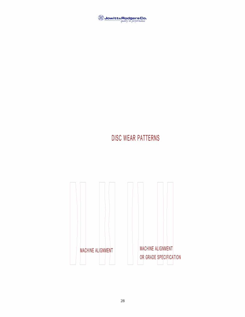
28

29
IV. GLOSSARY OF TERMS
TERM DEFINITION
Abrasive Also called ABRASIVE DISC, NUT INSERTED DISC,WHEEL, OR GRINDING WHEEL. The "cutting tool" used toremove stock from workpieces in double disc grinding. It iscylindrically shaped, having an I.D. and O.D. It is supportedfrom the back face and removes stock using the front face.
Adjusting Slide Previously referred to as a CHUCKING CYLINDER orCHUCKING PLATE. This device is the adjusting and slidemechanism for an adjustable entrance or exit guide.
Alignment The geometry relationships between the two grinding wheels,parts feeding fixture and the entrance and exit guides.
Anti-Backlash System An actuator that pulls rearward on the quill, eliminating backlashin the infeed system and preloads the quill in its housing.Typically includes an air cylinder on horizontal grinders and ahydraulic cylinder on a vertical grinder.
Back Pressure Compression forces on the exiting stream of workpieces from athroughfeed grinder. Such forces can be caused by post-processgauges or other downstream mechanisms. An exit drive roll oran inclined part path is often used to alleviate back pressure.
Bushing A round work holder in a rotary feedwheel or oscillator paddleused to hold the workpiece.
Centerhole The void region inside the I.D. of an abrasive disc. The diameterof the centerhole varies between applications and is very smallon throughfeed machines, only large enough to permit thepassage of coolant through the spindle.
Cycle Time (Machine) Time required for the machine to grind one workpiece.
Cycle Time (Floor-to-Floor) Average time that a grinding machine must be available toprocess (grind/load/unload/ gauge/etc.) one workpiece.
Disc Wheel Also called a STEEL BACK or a BACKING PLATE. Itprovides the mounting surface for the abrasive disc and supportsit structurally. The disc wheel is usually made of steel and boltsdirectly onto the spindle flange.
Entrance Guides Also called GUIDE PLATES. Wear resistant metallic platesused to accurately guide the unground workpiece as it entersbetween the abrasives. usually consists of one left hand and oneright hand guide.
Exit Drive Also called EXIT ROLL. A powered device to assistworkpieces along a desired path (on a through feed machine)after exiting from between the grinding wheels. Usually isadjusted to drive workpieces slightly faster than the feedingmechanism, thus avoiding unnecessary compression of the streamof workpieces between the abrasives.

30
Exit Guides Also called GUIDE PLATES. Wear resistant metallic platesused to guide the workpieces, after they exit from between theabrasives, along any desired post-grind path. Usually consists ofone left hand and one right hand guide. They do not touch theworkpiece until it is completely free from the abrasives.
Feed Rate The rate of travel, usually in inches per minute, of an abrasivewhen plunge grinding a workpiece.
Feed Wheel Also called a ROTARY CARRIER, CARROUSEL, OR FERRISWHEEL. A round plate with multiple openings to acceptworkpieces. It is used to drive workpieces along a circular pathbetween the opposed abrasives.
Floating Also called NESTING. Refers to a method of holding aworkpiece in its workholder while grinding. This method allowsthe workpiece to self center while grinding as opposed to"clamping" the part.
Gauge Also called a SIZER. On a double disc grinder this devicetypically is used to measure the thickness of ground workpieces.The device may be "in-process" (oscillator) or "post process" (allothers) and may be manual or automatic. Gauge signals may beused to automatically compensate the grinding machine forthickness changes or the read-out may provide a "visual only"output.
Gauge Finger Also called PROBE. A wear resistant device used to contact theground surface of the workpiece for the purpose of measuringpart size (thickness). A gauge finger can be used to measure aworkpiece either during the grind (oscillator machine/in-processgauging) or after the grind (Post process).
Grind Line A double disc grinder would have two grind lines, right and left.It is the intersection of the workpiece surface with the abrasiveduring grinding. It is not a true line, but would be plane on afreshly trued set of abrasives.
Grind Path Also called PART PATH. The path travelled by a workpiecewhile it makes contact with the abrasive face.
Grind Zone The path of the workpiece as it passes between the opposedabrasives.
Guide Bars Also called RAILS OR GUIDE RAILS. Wear resistant steelbars used on a through feed type double disc grinder. Upper andlower guidebars contain the workpieces in the vertical directionas they pass through the feeding mechanism, the grinding wheels,and any machine mounted thickness gauge.
Guide Bar Spacer A precision spacer placed between the guide bars and the lefthand entrance/exit guides. These spacers are configured tocenter the guide bars to the workpiece on the throughfeedgrinder.

31
Guide Bracket A structure to which a "fixed" entrance or exit guide is attached.
Head An assembly containing the main grinding wheel spindle, theabrasive feeding mechanism, and the slide.
Head Setting The geometric relationship of the two opposed grinding wheelsto each other when trued to a flat condition. A measure of thechange in gap between the abrasives, usually stated in terms of"front-to-back" and "top-to-bottom".
Hood A structural part of a double disc grinder used to act as awheelguard, contain coolant, and support the truing device aswell as some less critical tooling. On some older machines, thehood also supports parts feeding fixtures.
In-feed Also called "PICK" FEED, COMPENSATION,INCREMENTAL FEED. The motion of an abrasive to make upfor the fact that the face wears away during the grinding process.The amount of movement is a pre-selected amount occurring at a
frequency required to maintain the proper grind line.
Left Hand The end of a double disc grinder as observed from theworkpieces entry side.
Oscillation Also called a STROKE. This is one inward and outward cycle ofa workpiece between the abrasives on an oscillating type doubledisc grinder.
Oscillator A double disc grinder with a pivoting style workpiece feedingmechanism that oscillates the workpieces between the abrasives,from O.D. to I.D., a pre-set number of cycles. The abrasivessimultaneously plunge inward at a programmed cycle to removestock.
pH The degree of acidity of alkalinity of a solution. pH7 is regardeds neutral (pure distilled water). pH values from 0 to 7 indicateacidity and from 7 to 14 indicate alkalinity.
Plunge Grind Also called FACE GRIND. A grinding cycle where theabrasives feed into the workpiece at programmed rates to removestock. Used on oscillating type double disc grinders and someother miscellaneous types.
Pusher Bar A straight bar of rectangular cross-section used to pushworkpieces (one at a time) through the grind zone on a longstroke pusher feeder type double disc grinder.
Quill Also called a SLEEVE or WHEEL SLEEVE. A cylindricallyshaped precision slide used for moving the abrasive along thespindle axis. Houses the grinding wheel spindle and its bearings.
Right Hand The end of a double disc grinder as observed from the workpieceentry side.
Rotary Fixture A transmission used to support and transmit torque to thefeedwheel. Usually includes variable speed adjustments. The

32
feedwheel is mounted by bolting to an integral flange (rotaryhub) on one end of the rotary fixture spindle.
Rotary Hub The flange integral to the rotary fixture spindle. Used formounting the feedwheel.
Shelling Refers to the action of an abrasive whereby the usage orbreakdown is excessive. Shelling is not desirable, becausethickness and finish tolerances are difficult to achieve under thiscondition.
Size Refers to the thickness of a finish ground workpiece.
Spindle A rotating shaft, supported by bearings, bushings, etc. Oftenreferring to the shaft that supports the grinding wheel.
Spindle Flange Also called WHEEL COLLAR. The flange at the end of thespindle (usually integral to the spindle) used for mounting thegrinding wheel and its' steel backing plate.
Spindle Speed The rate of rotation of the main grinding spindle, usuallymeasured in revolutions per minute.
Spin Grinding When the workpiece is allowed or forced to spin while beingground, tolerances can often by improved. Spin grindinggenerally results in a cross-hatched surface finish on theworkpiece.
Stock The amount to be ground off a workpiece, either in total or per"pass". Usually is measured in inches (or millimeters), or couldbe stated in cubic inches per workpiece. In double discgrinding, it represents the amount in total to be ground off bothsides. For example, if each side had .005" to be removed, theworkpiece would contain .010" stock.
Surface Area Usually referring to the surface area of the grinding stock on aworkpiece.
Tooling A general term relating to parts of the grinder that make contactwith the workpieces. Tooling is typically made from wearresistant material but is generally considered replaceable.
Wheel Positioner A device that detects the location of an abrasive face. Wheelpositioners can be either contact or non-contact type and areusually used to monitor the location of only one abrasive disc.
Wheel Shapes The deviation in the shape of an abrasive face from a flat surface.
Workholder Also called a POCKET or a RETAINER. This is an item oftooling which restrains the workpiece during grinding. Theworkholder can either "clamp" or simply "nest" the part.
Workholding Paddle Also referred to as simply the PADDLE, WORKHOLDER,BLADE, etc. A device used on an oscillating type double discgrinder to contain and drive the workpiece while grinding.
Workpiece Also called the PART or PART PIECE. This is the item being

33
ground by the grinding machine.
Zip-Zip Also called SHUTTLE grinding. This refers to a style ofgrinding using an oscillating type parts feeder. In this case theabrasives are fixed during a grind cycle and move inwardbetween cycles only to compensate for abrasive wear. Eachworkpiece enters the abrasives, goes to the I.D. and then back outagain to be unloaded. This single stroke is referred to as "zip-zip" style.

PROBLEM SOLVING CHART
34
PROBLEM CAUSE SOLUTION REFERENCE
Improper head setting Adjust head settings See page 16
Speed up dresser See page 17
Replace worn dressing tool See page 17
Change to single point diamond or dresser cutters See page 17
Abrasives dull Softer wheel grade or more friable grain See page 16
Clean coolant tank See page 17
Provide adequate filtration See page 17
Dilute coolant strength and maintain pH 7-9 See page 17
Softer wheel grade See page 17
Abrasives loaded Different grain type See page 17
Dress the wheels See page 17
Check set-up See page 17
Abrasives out of flat Review abrasive spec if dressing is too frequent See page 17
Reduce progressive head setting See page 17
Review abrasive spec See page 17
>Pinch off= Re-orient work piece/review tooling design See page 17
Correct erratic feeding problem See page 18
>Steps= caused by hesitation in grind zone Eliminate interference at entry or exit See page 18
Poor Parallelism Coolant too hot Increase coolant capacity See page 18
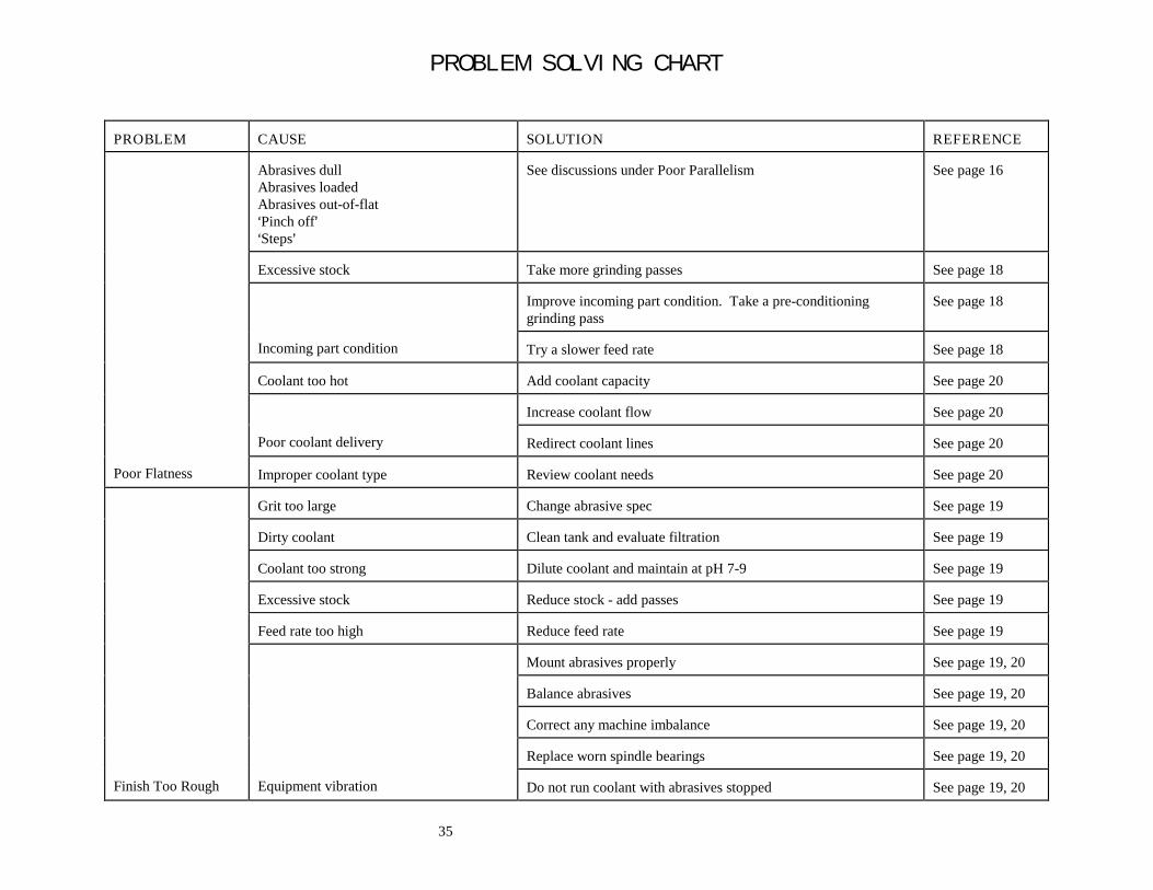
PROBLEM SOLVING CHART
35
PROBLEM CAUSE SOLUTION REFERENCE
Abrasives dullAbrasives loadedAbrasives out-of-flat>Pinch off=>Steps=
See discussions under Poor Parallelism See page 16
Excessive stock Take more grinding passes See page 18
Improve incoming part condition. Take a pre-conditioninggrinding pass
See page 18
Incoming part condition Try a slower feed rate See page 18
Coolant too hot Add coolant capacity See page 20
Increase coolant flow See page 20
Poor coolant delivery Redirect coolant lines See page 20
Poor Flatness Improper coolant type Review coolant needs See page 20
Grit too large Change abrasive spec See page 19
Dirty coolant Clean tank and evaluate filtration See page 19
Coolant too strong Dilute coolant and maintain at pH 7-9 See page 19
Excessive stock Reduce stock - add passes See page 19
Feed rate too high Reduce feed rate See page 19
Mount abrasives properly See page 19, 20
Balance abrasives See page 19, 20
Correct any machine imbalance See page 19, 20
Replace worn spindle bearings See page 19, 20
Finish Too Rough Equipment vibration Do not run coolant with abrasives stopped See page 19, 20
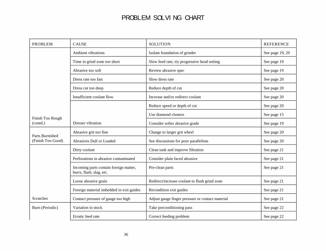
PROBLEM SOLVING CHART
36
PROBLEM CAUSE SOLUTION REFERENCE
Ambient vibrations Isolate foundation of grinder See page 19, 20
Time in grind zone too short Slow feed rate, try progressive head setting See page 19
Abrasive too soft Review abrasive spec See page 19
Dress rate too fast Slow dress rate See page 20
Dress cut too deep Reduce depth of cut See page 20
Insufficient coolant flow Increase and/or redirect coolant See page 20
Reduce speed or depth of cut See page 20
Use diamond clusters See page 15Finish Too Rough(contd.) Dresser vibration Consider softer abrasive grade See page 19
Abrasive grit too fine Change to larger grit wheel See page 20Parts Burnished(Finish Too Good) Abrasives Dull or Loaded See discussions for poor parallelism See page 20
Dirty coolant Clean tank and improve filtration See page 21
Perforations in abrasive contaminated Consider plain faced abrasive See page 21
Incoming parts contain foreign matter,burrs, flash, slag, etc.
Pre-clean parts See page 21
Loose abrasive grain Redirect/increase coolant to flush grind zone See page 21
Foreign material imbedded in exit guides Recondition exit guides See page 21
Scratches Contact pressure of gauge too high Adjust gauge finger pressure or contact material See page 21
Variation in stock Take preconditioning pass See page 22Burn (Periodic)
Erratic feed rate Correct feeding problem See page 22

PROBLEM SOLVING CHART
37
Fluctuating coolant flow check coolant system for restrictions See page 22

PROBLEM SOLVING CHART
38
PROBLEM CAUSE SOLUTION REFERENCE
Coolant too hot Increase coolant capacity See page 22
Coolant delivery insufficient (If burn areashows deep grain penetration)
Increase or redirect coolant See page 22
Excessive feed rate Slow feed rate See page 22
Too much stock Reduce stock, take more passes See page 22
Dull abrasiveLoaded abrasives (if burn area isburnished)
See discussions for parallelism See page 22
Burn (Every Piece) Improper head settings Try more shear or more progression See page 22
Entrance guides out of alignment Check set-up See page 23
Excessive clearance between the parts andentrance guides
Reduce clearance See page 23
Burr or nick on entrance guide Recondition entrance guide See page 23
Grind line drift (Halos on round parts;dubs on rectangular parts)
Shift grind line by infeeding the wheel contacting dubbed orhaloed surfaces
See page 23
Major variations in stock Add preconditioning pass See page 23
Variations in OD=s of abrasives Change or true abrasive OD=s See page 24
Coolant deflecting part at entrance Reduce flow at entrance or redirect flow See page 24
Part imbalance (Draft angle, etc.) Try reversing both spindles See page 24Blemishes and Marks(Dubbing at entry togrind zone) Non-uniform feed rate Correct feeding problem See page 24
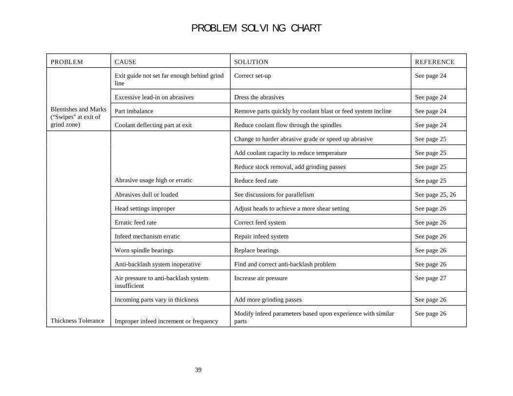
PROBLEM SOLVING CHART
39
PROBLEM CAUSE SOLUTION REFERENCE
Exit guide not set far enough behind grindline
Correct set-up See page 24
Excessive lead-in on abrasives Dress the abrasives See page 24
Part imbalance Remove parts quickly by coolant blast or feed system incline See page 24Blemishes and Marks(ASwipes@ at exit ofgrind zone) Coolant deflecting part at exit Reduce coolant flow through the spindles See page 24
Change to harder abrasive grade or speed up abrasive See page 25
Add coolant capacity to reduce temperature See page 25
Reduce stock removal, add grinding passes See page 25
Abrasive usage high or erratic Reduce feed rate See page 25
Abrasives dull or loaded See discussions for parallelism See page 25, 26
Head settings improper Adjust heads to achieve a more shear setting See page 26
Erratic feed rate Correct feed system See page 26
Infeed mechanism erratic Repair infeed system See page 26
Worn spindle bearings Replace bearings See page 26
Anti-backlash system inoperative Find and correct anti-backlash problem See page 26
Air pressure to anti-backlash systeminsufficient
Increase air pressure See page 27
Incoming parts vary in thickness Add more grinding passes See page 26
Thickness Tolerance Improper infeed increment or frequencyModify infeed parameters based upon experience with similarparts
See page 26

40