directx programming - computer graphics and -...
TRANSCRIPT

DirectX Programming
Computer Graphics, 2012 Spring
Jihye Yun

Programming with GPU
• Various APIs and technologies
– Graphics programming
– General-purpose GPU programming
Applications
DirectX OpenGL CUDA OpenCL
GPU

DirectX
• Components
• DirectX SDK (Software Development Kit) – Libraries, header files, utilities, sample codes and docs
DirectX 1.0
1995 1996 1998 1999 2000 2001 2003 2004 2006 2008
DirectX 2.0
DirectX 5.0
DirectX 6.0
2002
DirectX 7.0
DirectX 8.0
DirectX 9.0
DirectX 9.0c
DirectX 10.0
2009
DirectX 11.0
2D and 3D graphics Direct3D
Sound XAudio2, X3DAudio, XACT
Input XInput

Installation
• You can download from Microsoft’s homepage
– Latest version: June 2010
– http://www.microsoft.com/download/en/details.aspx?id=6812
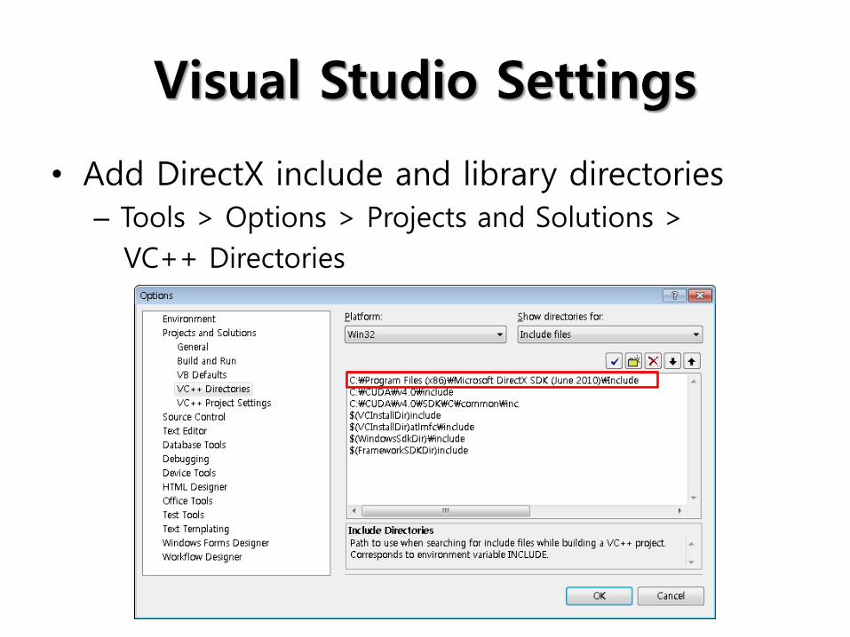
Visual Studio Settings
• Add DirectX include and library directories
– Tools > Options > Projects and Solutions >
VC++ Directories

Visual Studio Settings
• Add DirectX include and library directories
– Tools > Options > Projects and Solutions >
VC++ Directories

Sample and Tutorial Codes
• Sample codes
– [DX directory]/Samples/C++/Direct3D11
• Tutorial codes
– [DX directory]/Samples/C++/Direct3D11/Tutorials

Sample and Tutorial Codes
• Using Sample Browser
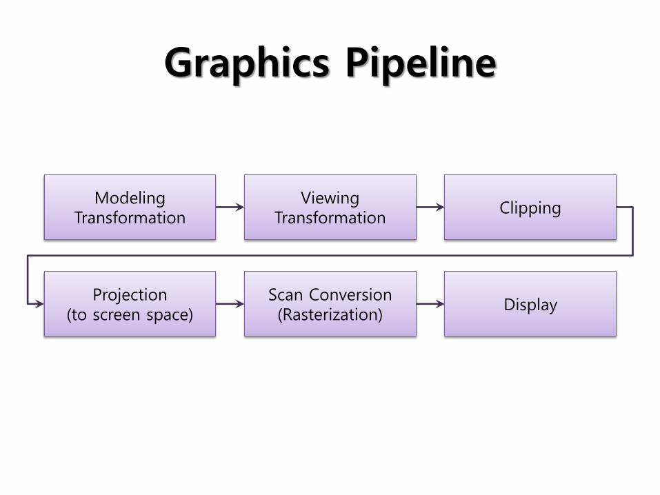
Graphics Pipeline
Modeling Transformation
Viewing Transformation
Clipping
Projection (to screen space)
Scan Conversion (Rasterization)
Display

Direct3D Pipeline
• Stages
– Configured using API
• Shader stages
– Programmable using HLSL
Input-Assembler Stage
Rasterizer Stage
Stream-Output Stage
Output-Merger Stage
Vertex-Shader Stage
Geometry-Shader Stage
Pixel-Shader Stage
Memory Resources (Buffer, Texture, Constant Buffer)
Stage Abbr. Description
Input-Assembler IA Supply data to pipeline
Vertex-Shader VS Process vertices
Rasterizer RS Convert vector data to pixels
Pixel-Shader PS Generate per-pixel data
Output-Merger OM Generate final pipeline result

Input-Assembler Stage
• Vertices
• Indices
• Primitive
– Composed of one or more vertices
– Point, line and triangle
– Primitive types • Point list, line list, line strip,
triangle list, triangle strip, …
Input-Assembler Stage
Rasterizer Stage
Stream-Output Stage
Output-Merger Stage
Vertex-Shader Stage
Geometry-Shader Stage
Pixel-Shader Stage
Memory Resources (Buffer, Texture, Constant Buffer)
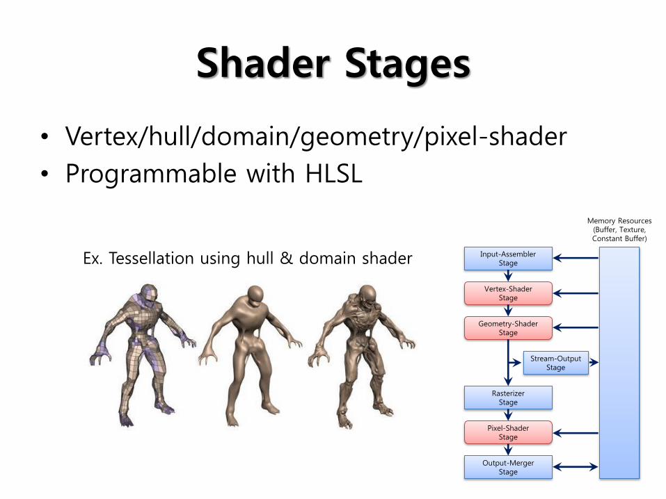
Shader Stages
• Vertex/hull/domain/geometry/pixel-shader
• Programmable with HLSL
Input-Assembler Stage
Rasterizer Stage
Stream-Output Stage
Output-Merger Stage
Vertex-Shader Stage
Geometry-Shader Stage
Pixel-Shader Stage
Memory Resources (Buffer, Texture, Constant Buffer)
Ex. Tessellation using hull & domain shader

Shader Stages
• Vertex/hull/domain/geometry/pixel-shader
• Programmable with HLSL
Input-Assembler Stage
Rasterizer Stage
Stream-Output Stage
Output-Merger Stage
Vertex-Shader Stage
Geometry-Shader Stage
Pixel-Shader Stage
Memory Resources (Buffer, Texture, Constant Buffer)
Function Description
Creating shader object ID3D11Device::CreateVertexShader
Setting shader to use ID3D11DeviceContext::VSSetShader
Setting up each shader stage
ID3D11DeviceContext::VSSetConstantBuffer ID3D11DeviceContext::VSSetShaderResources ID3D11DeviceContext::VSSetSamplers

HLSL
• High Level Shading Language for DirectX
• For writing codes for programmable shaders in Direct3D pipeline
• Implements series of shader models
Shader Model Shader Profiles Direct3D support
Shader model 1 vs_1_1 Direct3D 9
Shader model 2 ps_2_0, ps_2_x, vs_2_0, vs_2_x
Shader model 3 ps_3_0, vs_3_0
Shader model 4 gs_4_0, ps_4_0, vs_4_0, gs_4_1, ps_4_1, vs_4_1 Direct3D 10
Shader model 5 cs_4_0, cs_4_1, cs_5_0, ds_5_0, gs_5_0, hs_5_0, ps_5_0, vs_5_0 Direct3D 11

Vertex-Shader Stage
• Process each vertex of primitives from IA
– Performs per-vertex operations (transformations, morphing, per-vertex lighting, …)
• Single input vertex, single
output vertex
– Always run on all vertices
• Mandatory stage
Input-Assembler Stage
Rasterizer Stage
Stream-Output Stage
Output-Merger Stage
Vertex-Shader Stage
Geometry-Shader Stage
Pixel-Shader Stage
Memory Resources (Buffer, Texture, Constant Buffer)
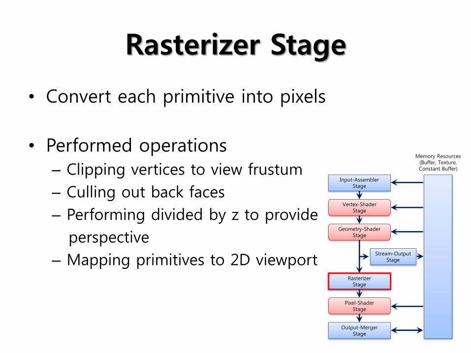
Rasterizer Stage
• Convert each primitive into pixels
• Performed operations
– Clipping vertices to view frustum
– Culling out back faces
– Performing divided by z to provide
perspective
– Mapping primitives to 2D viewport
Input-Assembler Stage
Rasterizer Stage
Stream-Output Stage
Output-Merger Stage
Vertex-Shader Stage
Geometry-Shader Stage
Pixel-Shader Stage
Memory Resources (Buffer, Texture, Constant Buffer)

Pixel-Shader Stage
• Process each pixel from rasterizer stage
• Enable rich shading techniques and more
• Generated output
– Colors to be written to render
targets
– Optional depth value
• All texture methods available
• Mandatory Stage
Input-Assembler Stage
Rasterizer Stage
Stream-Output Stage
Output-Merger Stage
Vertex-Shader Stage
Geometry-Shader Stage
Pixel-Shader Stage
Memory Resources (Buffer, Texture, Constant Buffer)

Output-Merger Stage
• Generate final rendered pixel color
– Combine pipeline state, pixel data generated by PS, contents of the depth/stencil buffers
• Determine visibility of pixels
(depth-stencil testing)
• Blend final pixel colors
Input-Assembler Stage
Rasterizer Stage
Stream-Output Stage
Output-Merger Stage
Vertex-Shader Stage
Geometry-Shader Stage
Pixel-Shader Stage
Memory Resources (Buffer, Texture, Constant Buffer)

Tutorial 1: Creating Device
• Create device object and swap chain
– Device • Used to perform both rendering and resource creation
– Swap chain • Encapsulate two or more buffers used for rendering and
display
• Front buffer: presented to display device
• Back buffer: render target
• Presents back buffer by swapping two buffers

Creating Device
ID3D11Device* g_pd3dDevice = NULL;
IDXGISwapChain* g_pSwapChain = NULL;
ID3D11DeviceContext* g_pImmediateContext = NULL;
if ( FAILED ( D3D11CreateDeviceAndSwapChain ( NULL,
D3DDRIVER_TYPE_HARDWARE, NULL, 0, featureLevels,
numFeatureLevels, D3D11_SDK_VERSION, &sd,
&g_pSwapChain, &g_pd3dDevice, NULL, &g_pImmediateContext ) ) )
{
return FALSE; }

Creating Device
DXGI_SWAP_CHAIN_DESC sd;
Zeromemory( &sd, sizeof(sd) );
sd.BufferCount = 1;
sd.BufferDesc.Width = 640;
sd.BufferDesc.Height = 480;
sd.BufferDesc.Format = DXGI_FORMAT_R8G8B88_UNORM;
sd.BufferDesc.RefreshRate.Numerator = 60;
sd.BufferDesc.RefreshRate.Denominator = 1;
sd.BufferUsage = DXGI_USAGE_RENDER_TARGET_OUTPUT;
sd.OutputWindow = g_hWnd;
sd.SampleDesc.Count = 1;
sd.SampleDesc.Quality = 0;
sd.Windowed = TRUE;

Create a Render Target View
• Resource view
– Allow a resource to be bound to the graphics pipeline at a specific stage
• Render target view is a type of resource view
– Pixel shader can simultaneously render to at least eight separate render targets
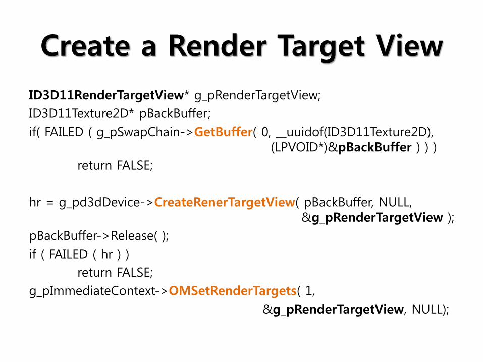
Create a Render Target View
ID3D11RenderTargetView* g_pRenderTargetView;
ID3D11Texture2D* pBackBuffer;
if( FAILED ( g_pSwapChain->GetBuffer( 0, __uuidof(ID3D11Texture2D), (LPVOID*)&pBackBuffer ) ) )
return FALSE;
hr = g_pd3dDevice->CreateRenerTargetView( pBackBuffer, NULL, &g_pRenderTargetView );
pBackBuffer->Release( );
if ( FAILED ( hr ) )
return FALSE;
g_pImmediateContext->OMSetRenderTargets( 1,
&g_pRenderTargetView, NULL);

Modifying Message Loop
MSG msg = {0};
while ( WM_QUIT != msg.message )
{
if( PeekMessage ( &msg, NULL, 0, 0, PM_REMOVE ) )
{
TranslateMessage( &msg );
DispatchMessage( & msg ); }
else
{
Render(); // Do some rendering
} }

Rendering Code
void Render( )
{
//
// clear the backbuffer
//
float ClearColor[4] = { 0.0f, 0.125f, 0.6f, 1.0f };
g_pd3dDevice->ClearRenderTargetView( g_pRenderTargetView,
ClearColor);
g_pSwapChain->Present( 0, 0 );
}
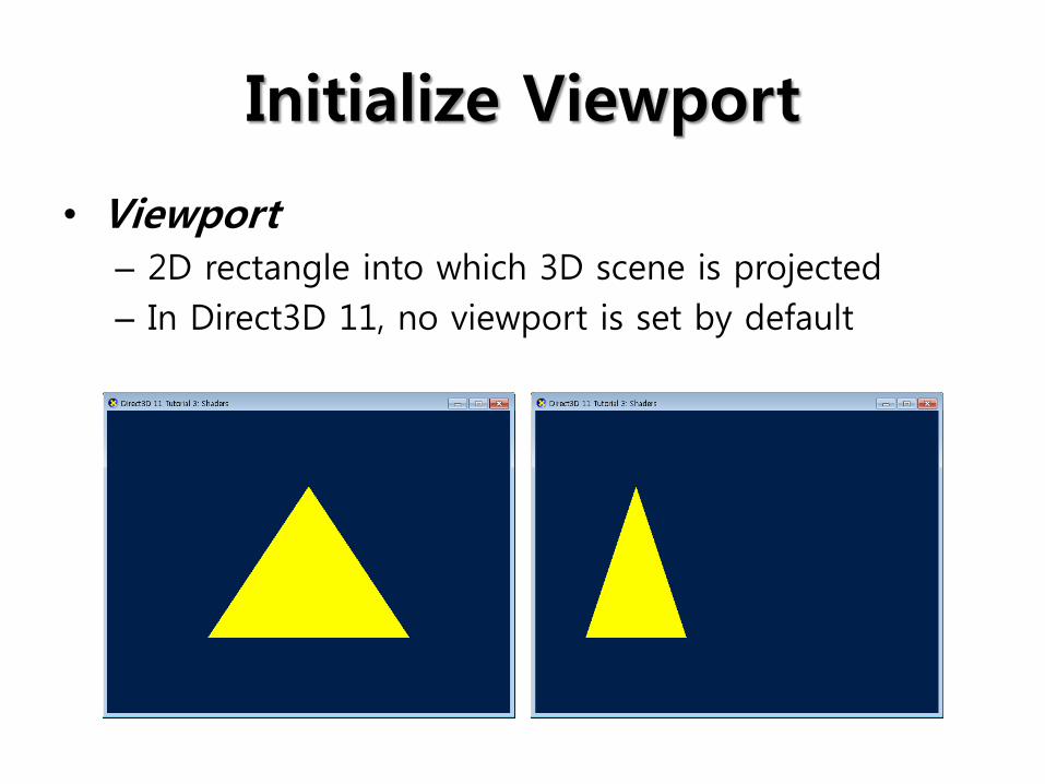
Initialize Viewport
• Viewport – 2D rectangle into which 3D scene is projected
– In Direct3D 11, no viewport is set by default

Initialize Viewport
D3D11_VIEWPORT vp;
vp.Width = (FLOAT)width;
vp.Height = (FLOAT)height;
vp.MinDepth = 0.0f;
vp.MaxDepth = 1.0f;
vp.TopLeftX = 0;
vp.TopLeftY = 0;
g_pImmediateContext->RSSetViewports( 1, &vp );

Tutorial 1: Creating Device
• Result

Tutorial 2: Rendering a Triangle
• How do we pass the information to the GPU?

Input Layout
• Describe the structure of vertices in a way that can be understood by the GPU
• Each vertex attribute can be described with the D3D11_INPUT_ELEMENT_DESC structure
D3D11_INPUT_ELEMENT_DESC {
SemanticName, SemanticIndex, Format, InputSlot,
AlignedByteOffset, InputSlotClass,
InstanceDataStepRate
};

Input Layout
struct SimpleVertex{
XMFLOAT3 Pos; // Position };
// Define the input layout
D3D11_INPUT_ELEMENT_DESC layout[ ] = {
{ “POSITION”, 0, DXGI_FORMAT_R32G32B32_FLOAT, 0, 0
D3D11_INPUT_PER_VERTEX_DATA, 0 },
};
UINT numElements = ARRAYSIZE( layout );
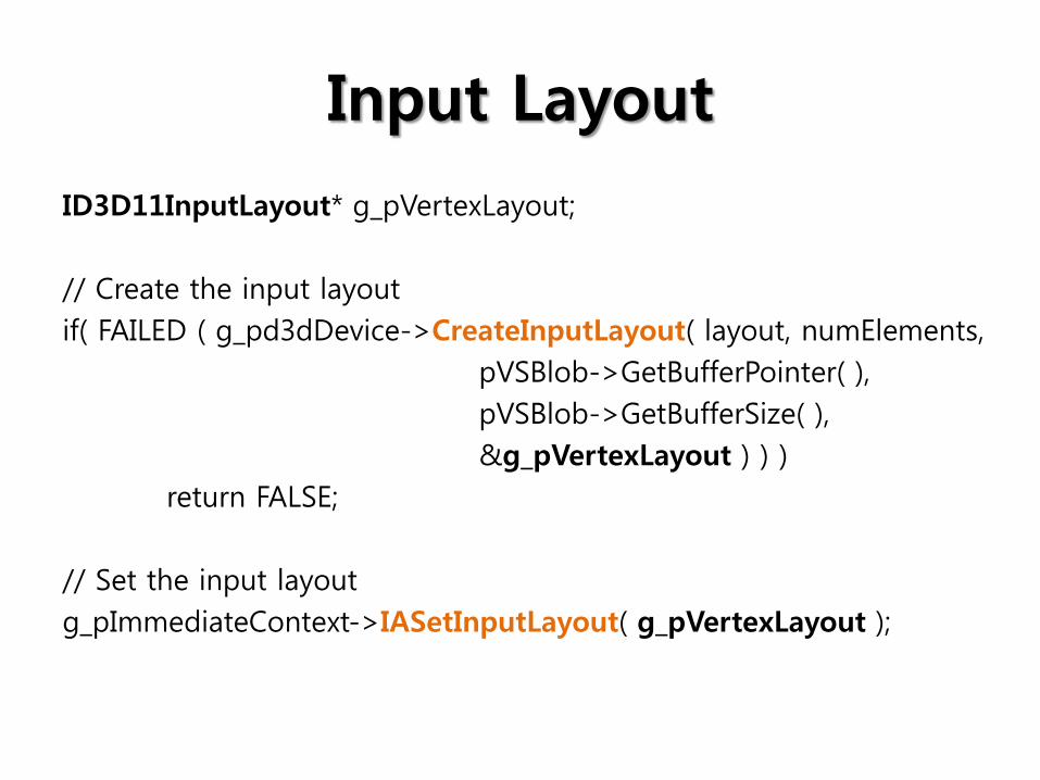
Input Layout
ID3D11InputLayout* g_pVertexLayout;
// Create the input layout
if( FAILED ( g_pd3dDevice->CreateInputLayout( layout, numElements,
pVSBlob->GetBufferPointer( ),
pVSBlob->GetBufferSize( ),
&g_pVertexLayout ) ) )
return FALSE;
// Set the input layout
g_pImmediateContext->IASetInputLayout( g_pVertexLayout );

Create Vertex Buffer
SimpleVertex vertices[ ] = {
XMFLOAT3( 0.0f, 0.5f, 0.5f );
XMFLOAT3( 0.5f, -0.5f, 0.5f );
XMFLOAT3( -0.5f, -0.5f, 0.5f );
};
D3D11_BUFFER_DESC bd;
ZeroMemory( &bd);
bd.Usage = D3D11_USAGE_DEFAULT;
bd.ByteWidth = sizeof( SimpleVertex ) * 3;
bd.BindFlags = D3D_BIND_VERTEX_BUFFER;
bd.CPUAccessFlags = 0;
bd.MiscFlags = 0;

Create Vertex Buffer
D3D11_SUBRESOURCE_DATA InitData;
ZeroMemory( & InitData, sizeof( InitData ) );
InitData.pSystem = vertices;
// Create vertex buffer
ID3D11Buffer* g_pVertexBuffer = NULL;
if( FAILED( g_pd3dDevice->CreateBuffer( &bd, &InitData,
&g_pVertexBuffer ) ) )
return FALSE;
// Set vertex buffer
UINT stride = sizeof( SimpleVertex );
UINT offset = 0;
g_ImmediateContext->IASetVertexBuffers( 0, 1, &g_pVertexBuffer,
&stride, &offset);

Primitive Topology
// Set primitive topology
g_pImmediateContext->IASetPrimitiveTopology(
D3D_PRIMITIVE_TOPOLOGY_TRIANGLELIST);
D3D_PRIMITIVE_TOPOLOGY_POINTLIST
D3D_PRIMITIVE_TOPOLOGY_LINELIST
D3D_PRIMITIVE_TOPOLOGY_LINESTRIP
D3D_PRIMITIVE_TOPOLOGY_TRIANGLELIST
D3D_PRIMITIVE_TOPOLOGY_TRIANGLESTRIP
….

Rendering Triangle
ID3D11VertexShader* g_pVertexShader = NULL;
ID3D11PixelShader* g_pPixelShader = NULL;
// Render a triangle
g_pImmediateContext->VSSetShader( g_pVertexShader, NULL, 0 );
g_pImmediateContext->PSSetShader( g_pPixelShader, NULL, 0 );
g_pImmediateContext->Draw( 3, 0 );

Tutorial 2: Rendering a Triangle
• Result

Tutorial 3: Shaders
• Shaders – Short programs that, executed by the GPU, take
certain input data, process that data, and then output the result to the next stage of pipeline • Vertex shader
• Pixel shader
• Geometry shader
• Hull/domain shader
• When rendering with Direct3D 11,
– The GPU must have a valid vertex shader and pixel shader

Vertex Shader
• The application passes vertex data to the GPU in the form of a vertex buffer
• GPU iterates through the vertices in the vertex buffer, executes the active vertex shader once for each vertex
float4 VS( float4 Pos : POSITION ) : SV_POSITION
{
return Pos; }

Pixel Shader
• Rasterization
float4 PS( float4 Pos : SV_POSITION ) : SV_Target
{
return float4( 1.0f, 1.0f, 0.0f, 1.f ); // Yellow with alpha = 1 }

Creating Shaders
ID3DBlob* pVSBlob = NULL, *pPSBlob = NULL, *pErrorBlob = NULL;
// Compile the vertex shader
if( FAILED( D3DX11CompileFromFile( “Tutorial03.fx”, NULL, NULL,
“VS”, “vs_4_0”, D3DCOMPILE_ENABLE_STRICNESS,
NULL, NULL, &pVSBlob, &pErrorBlob, NULL ) ) )
return FALSE;
// Compile the pixel shader
if( FAILED( D3DX11CompileFromFile( “Tutorial03.fx”, NULL, NULL,
“PS”, “ps_4_0”, D3DCOMPILE_ENABLE_STRICNESS,
NULL, NULL, &pPSBlob, &pErrorBlob, NULL ) ) )
return FALSE;

Creating Shaders
ID3D11VertexShader* g_pVertexShader = NULL;
ID3D11PixelShader* g_pPixelShader = NULL;
// Create the vertex shader
if( FAILED( g_pd3dDevice->CreateVertexShader(
pVSBlob->GetBufferPointer(), pVSBlob->GetBufferSize(),
NULL, &g_pVertexShader ) ) )
return FALSE;
// Create the pixel shader
if( FAILED( g_pd3dDevice->CreatePixelShader(
pPSBlob->GetBufferPointer(), pPSBlob->GetBufferSize(),
NULL, &g_pPixelShader ) ) )
return FALSE;

Rendering Triangle
// Render a triangle
g_pImmediateContext->VSSetShader( g_pVertexShader, NULL, 0 );
g_pImmediateContext->PSSetShader( g_pPixelShader, NULL, 0 );
g_pImmediateContext->Draw( 3, 0 );

Tutorial 3: Shaders
• Result