directional hearin ign th japanese e quail {coturnix coturnix
TRANSCRIPT

J. exp. Biol. (1980). 86. OS-'S' 135With 8 figures
Printed in Great Britain
DIRECTIONAL HEARING IN THE JAPANESE QUAIL{COTURNIX COTURNIX JAPONIC A)
I. ACOUSTIC PROPERTIES OF THE AUDITORY SYSTEM
BY K. G. HILL,* D. B. LEWIS.f M. E. HUTCHINGSAND R. B. COLES
Department of Biology, City of London Polytechnic, Old Castle Street,London Ei 7NT, U.K.
(Received 3 August 1979)
SUMMARY
The auditory tympana in the quail, Coturnix coturnix japonica (L.) are in-ternally coupled by an interaural air space. Unilaterally applied sound causingvibration of the ipsilateral tympanum is conducted through the interauralcavity to the inside surface of the contralateral tympanum. In a free soundfield at frequencies up to 3150 Hz, sound pressure at the external surface ofthe tympanum contralateral to the source is within about 3 dB of the pressureexterior to the ipsilateral tympanum. Sound pressures developed at the innersurfaces of the tympana are of similar amplitude to the external pressures atseveral frequencies in the range 800-6300 Hz. In addition, pressure ateach side of the tympanum ipsilateral to the source are generally out of phase,whereas pressures at each side of the contralateral tympanum are relativelyclose to the same phase. From measurements of amplitude and phase of theinteracting pressures at the tympanum, the calculated driving pressure atthe ipsilateral tympanum exceeds that at the contralateral tympanum by10-20 dB over a range of frequencies. The auditory tympana in quail haveconsiderable inherent directionality, therefore, due to their function aspressure-gradient receivers. Anatomical analogies with anurans and reptilesindicate that they derive directional hearing from the same acoustic mechan-ism that operates in the quail.
INTRODUCTION
To perceive sound the ears of most terrestrial animals utilize a light tympanicmembrane which is exposed directly, or via a canal, to the exterior. An air cavityexists behind the tympanum so that it is sensitive to the small, rapid changes inambient pressure associated with a sound wave. In a sound field, the force causingthe tympanum to vibrate is derived from the instantaneous difference between theair pressure acting on its external surface and the pressure behind the tympanum inthe tympanic cavity. This general description holds for crickets, locusts, bush-crickets, cicadas, moths (representing several independently evolved insect auditory
• Present address, Department of Neurobiology, Research School of Biological Sciences, AustralianNational University, Canberra, Australia.
t To whom requests for reprints should be sent.

136 K. G. HILL AND OTHERS
systems) and vertebrate ears. Sound localization using two such ears placed laterallydepends on the production of a physiological difference between the afferent auditoryresponses from each ear, the sense of this difference indicating on which side of thebody the sound source is located.
Many terrestrial animals have evolved systems of communication using soundsignals with wavelengths many times longer than the dimensions of their bodies. Insuch cases, and where the two tympana are exposed to the air medium directly orvia a short tube (but there are no pinnae), sound pressures reaching the externalsurfaces of the two tympana may be expected to be of similar amplitude regardless ofthe location of the source, because the attenuation of pressure due to the animal'shead or body will be small. If the anatomical distance between the ears is less thanabout 3 cm, the maximum time delay between the onset of the pressure wave at eachof the tympana will be less than 100 /is, which is an extremely short interval forreliable neural coding. To enable directional hearing in such animals, therefore, amechanism seems necessary by means of which the amplitude of vibration of each ofthe auditory tympana changes according to the direction of propagation of the soundwave, despite the almost constant sound pressure reaching the external surface ofeach tympanum for all directions of the sound source. Such a mechanism is thepressure-gradient receiver (Michelsen, 1971; Lewis, 1974; Michelsen & Nocke,1974), in which sound pressures of similar amplitude are applied to the front and backsurfaces of the tympanum and the amplitude of its resulting vibration depends on thephase difference between the inside and outside pressures. The phase differenceacross the tympanum may vary according to the direction of the incident sound waveand if it becomes very small, the force driving the tympanum is sharply reduced. Thismechanism enables directional hearing in crickets (Hill & Boyan, 1977), locusts(Miller, 1977) and cicadas (Fletcher & Hill, 1978). In each of these animals, soundpressures of similar amplitudes act on the front and back surfaces of each tympanumbecause sound is conducted between the inside surfaces of the tympana through anair space in the body, i.e. the auditory tympana are acoustically coupled internally.
In frogs, small reptiles and small birds, sound pressures on the external surfaces ofthe tympana will be of similar amplitudes when wavelengths are long with respect todimensions of the head. In each of these vertebrate classes, however, the insidesurfaces of the auditory tympana are connected by ducts produced by expansion ofthe eustachian tubes. Evidence that sound is transmitted through the head fromone tympanum to the other is available in each case (e.g. Strother, 1959; Wever &Vernon, 1957; Schwartzkopff, 1952). Thus, in these vertebrates the auditory tympanaought to show characteristics of pressure-gradient receivers.
In this paper, we describe sound conduction through the auditory system in thequail Coturnix coturnix japonica, in order to specify the acoustic conditions existingat each auditory tympanum when sound is incident from different directions in thehorizontal plane. A physical mechanism for directional hearing in this bird utilizingthe principle of the pressure-gradient receiver can be demonstrated when we computethe directional response of the tympanum, to a first approximation, using measure-ments of the sound pressure amplitude and phase existing at the front and backsurfaces of the tympanum when the bird is in a free sound field. The study is extendedto the responses of auditory receptors in the following paper.

Auditory system of quail 137
MATERIALS AND METHODS
Adult male and female quail, Coturnix coturnix japonica, were obtained from acommercial breeder. Birds were killed (intramuscular Nembutal) immediately priorto experiments. They were held in a natural position by cementing the cranium,exposed between the eyes, to a rigid stand made from small diameter metal tubing(see Fig. 1 A), Initially, the whole bird was mounted on the stand, the body beingsupported under the wings and by the feet. Most measurements, however, were madeon isolated heads separated from the body about three inches below the jaw. Theabsence of the body did not affect sound pressures measured around the head whena loudpeaker was placed at different positions in the horizontal plane.
Sound pressure was measured at three positions in the quail's auditory system; atthe external opening of the meatus, inside the meatus but external to the auditorytympanum, and inside the interaural cavity (see below) near the inside surface ofone auditory tympanum. The microphone (see below) was directed vertically upwardsfor all measurements, and when in the required position, it was firmly clamped tothe bird's stand. Feathers over and around the external opening of the meatus wereremoved. For measurements outside the meatus, the microphone was held againstthe side of the head with its end at the centre of the meatus opening. For internalmeasurements, neck muscles were removed on one side exposing the ventral surfaceof the skull or the ventral wall of the meatus. For access to the meatus, the proximalpart of the lower jaw was also removed. A hole was cut in the wall of the meatus orin the ventral surface of the skull to admit the microphone, which was then clampedand sealed in position with petroleum jelly (Vaseline). Following such measurementsin intact auditory systems we checked that no material was occluding cavities or incontact with the tympana as a result of locating the microphone.
Sound was presented to the bird head either unilaterally to one meatus only, or ina free field in anechoic conditions. For unilateral presentation, sound was conductedfrom a loudspeaker (acoustically isolated from the bird) along plastic tubing (length3 m, bore 10 mm), the end of which was held over the meatus and sealed against theside of the head with Vaseline. In the free field, the bird was mounted on a thin metalpost (approximately 1 m from the floor) in the centre of an acoustically insulated,anechoic chamber (see Results), having approximate internal dimensions of 2-5 x 2-5x 2-0 m and lined on all internal surfaces with rockwool wedges. The loudspeaker wasmounted on a pivoted arm and could be rotated through 360° in the horizontal planeat a constant 1-05 m from the position of the microphone, which was centred in theplane of rotation of the loudspeaker using a plumb-line. Calibrations were madeof the sound field (see below), but in addition, bird heads were routinely mountedfacing different directions in the anechoic chamber.
Pure tone, continuous sound was produced by amplifying the sinusoidal output ofa waveform generator (Phillips GM2317), passing the signal through a step-wiseattenuator (Hatfield 2125), monitoring the voltage on an oscilloscope and feeding thesignal to a loudspeaker (Radio Spares 243031). Frequency was set to o-i % accuracyusing a calibrated electronic counter (Heath, Co.). All measurements of sound pressurelevel and phase were made with a $ in. condenser microphone (Bruel and Kjaer type'4138), a -J-octave bandpass filter set (Bruel and Kjaer type 1612) and a measuring

K. G. HILL AND OTHERS
Fig. i. Drawings to illustrate aspects of the auditory system in the quail. (A) Arrangement ofthe head mounted on a stand for measurement of sound pressure in the auditory system usinga condenser microphone. (B) Appearance of a vertical, transverse section through the quailhead at the level of the auditory tympana: t, tympanum; c, interaural cavity; b, braincase.
amplifier (Bruel and Kjaer type 2107). Sound pressure levels used were in the range75-85 dB re. 2 x io~5N/m2. Measurements of the relative phase of the sound pressureat the microphone were made as follows. The sinusoidal signal fed to the loudspeakerwas also applied to one beam of a dual beam oscilloscope (Tektronix 5441) on whichthe sweep speed and trigger level were adjusted at each frequency so that one completecycle of the sine wave occupied the width of the oscilloscope screen graticule and thesweep started at a fixed point in the wave (the negative-going zero crossing). Assuminga constant phase relationship at each frequency between the voltage fed to the loud-speaker and the sound pressure produced, the voltage signal provided an arbitraryzero phase for reference at each frequency. The response of the condenser microphonewas monitored from the measuring amplifier and displayed on the second beam ofthe oscilloscope. For each frequency, therefore, the phase of the sound pressure atthe microphone, relative to an arbitrary zero phase, was indicated as a proportion of

Auditory system of quail 139
*>ne complete cycle by the horizontal distance between corresponding zero crossings ofthe two traces on the oscilloscope screen. In all measurements, the microphone wasused with a short length of plastic tubing fitted over the cartridge to prevent materialoccluding the grid or contacting the membrane. This tube extended about 2 mm infront of (and behind) the grid. Its presence had no measurable effect on the responseof the microphone at the sound frequencies used in these experiments.
For calibration of the sound field in the chamber, the microphone alone wasclamped to the post and directed vertically upwards at the centre of the plane ofrotation of the loudspeaker. Pressure amplitude and phase were measured for constantoutput of the signal generator, at each fequency used in the experiments, when theloudspeaker was shifted through 3600 in steps of 300.
The sound pressures acting on the front and back surfaces of the auditory tympanumin the quail depend on sound transmission through the meatus, past the tympanumand through the interaural cavity (see below). Transmission through each element wasassessed when sound was applied unilaterally to one meatus by means of the tube.Initially, the microphone was positioned at the external opening of the meatus, thesound delivery tube was sealed in place over it and sound levels were measured ateach frequency for calibrated signal voltages fed to the loudspeaker. The microphonewas then positioned inside the interaural cavity near the tympanum ipsilateral to thesound source, and sound measurements were repeated using the same signal para-meters. Further sets of measurements were made when the sound tube was appliedto the meatus contralateral to the microphone and after each of the auditory tympanawere largely removed with a pair of curved forceps.
The bird head forms an impedance at the end of the sound tube and hence, changesto the auditory system may alter this impedance and lead to changes in the soundpressure in the tube, i.e. the source pressure at the entrance to the meatus. As acontrol, therefore, measurements were made in the tube when positioned over onemeatus, before and after the removal of both auditory tympana. Sound pressures atthe entrance to the meatus before and after removal of both tympana were within2 dB at all frequencies except 1600 Hz where a decrease of 4 dB occurred. Similarly,phase changed by less than 10% at all frequencies after removal of the tympana.
RESULTS
Calibration of the free sound field
Sound pressure and phase were measured in the anechoic chamber at the centre ofrotation of the loudspeaker for 12 positions of the loudspeaker separated by 300.Variations in pressure and phase for the relevant range of frequencies are shown inTable 1. Sound pressure level was generally within + 2 dB and phase was within+ 7-5 % of 27T as the loudspeaker was rotated in the chamber. For one position of theloudspeaker (2700), a greater variation in sound pressure (up to ± 3-5 dB) occurred,but only at 1630 and 2000 Hz. This is attributed to an unaviodable projection in thechamber. For any frequency, there were no abrupt changes in pressure and phase asthe loudspeaker was moved through 3600 and each preparation was routinely pointedpn a different direction.

140 K. G. HILL AND OTHERS
Table 1. Total variation in two parameters of the sound field at the centre of the anechoicchamber when the loudspeaker was rotated through 3600
Frequency (Hz)
500630800
100012501630200025003'So4000500063008000
Variation in soundpressure level (dB)
± 0 6± 1 - 0±0-5± 1 0± 2 0
±3-5± 3 0±0-5±o-6± 0 3±0-2± i - 8± i - S
Variation inphase (% of zn)
±i '5± 1 0±5'O±4'°±VS±6-5± I - I
± i - 5± 1 - 0± i - o
±2-5±i-S±4-0
Anatomy of the auditory system
Anatomical aspects of the auditory system in the quail are illustrated in Fig. 1. Theexternal opening of the meatus is a simple, ovoid hole in the side of the head, normallycovered by a fan of delicate feathers. The meatus leads down and back to the tym-panum, it is about 4 mm in length, it has a minimal cross-sectional area of approxi-mately 3 mm2, and it is lined with epidermis. The auditory tympanum is a light mem-brane, approximately ovoid and about 8 mm2 in area. It is distended outward by thecolumella. Behind the tympanum is an air-filled cavity formed in the bone of the skull.This cavity extends dorsally and posteriorly towards the midline behind the braincase.Ventrally, the cavity extends to the midline where it is constricted; however, itconnects with the cavity on the opposite side. Thus, a continuous air-filled passageruns across the head between the inside surfaces of the auditory tympana. The internaldistance between the tympana is about 12 mm. The interaural cavity is bounded bythe spongy matrix of the skull. The total air space between the ears extends, therefore,throughout the pneumaticized region of the skull bones.
Sound conduction through the auditory system
Sound pressure levels measured at different positions in the auditory system willdepend on the extent to which the system is intact or modified and on the relativeamplitudes and phases of the pressures at each ear. When sound is applied unilaterally,measurements of pressure levels at different positions along passages in the systemor on each side of one of the tympana give some indication of the acoustic transmissionproperties of those elements. The 'gains' (differences between pairs of measurementsin dB) thus obtained may not precisely characterize the elements themselves, for ineach case transmission will depend on the state of the remainder of the system. Themeasurements to be described, however, do provide an insight into the functioning ofthe auditory system as a whole.
Fig. 2 shows the difference in level between the unilaterally applied sound pressureat the entrance to the meatus and the pressure just inside the position of the ablated!ipsilateral tympanum. This graph indicates that sound energy entering the head

+4
CO
'3O
Auditory system of quail
Frequency (kHz)10 20 40
141
8 0
-16
-20 L
Fig. 2. Gain of the meatus, defined as the difference between the sound pressure in the inter-aural cavity near the position of the ipsilateral tympanum after ablation of the tympanum andthe sound pressure at the entrance to the meatus. Sound was applied unilaterally to one meatus,the contralateral tympanum was intact. Means and standard errors are shown for six prepara-tions.
AFrequency (kHz)
0-5 10 [ _L 40 800
3 -4
o.>
-12O
- 1 6
3
0-5 10 20 40 80Fig. 3. (A) Gain of the auditory tympanum averaged for six preparations. With sound appliedunilaterally, pressure behind the intact ipsilateral tympanum, relative to that at the sameposition after ablation of the tympanum, is appreciably diminished at low frequencies(o'5~io kHz). At higher frequencies, loss of sound pressure across the tympanum is very small.(B) Difference between the phase of the pressure behind the intact ipsilateral tympanum forunilateral sound input and the phase of the pressure at the entrance to the meatus. From2000 to 3150 Hz, the phase shift across the tympanum (and the meatus) is close to njz. At higherfrequencies, reversion to smaller observed phase differences are interpreted as phase shiftsgreater than zit. In both cases data are obtained from six preparations.

142 K. G. HILL AND OTHERS
DO•a
o
1 - 1 2
-16
Frequency (kHz)
V
10 20 40
Fig. 4. (A) Gain of the interaural cavity measured for unilateral sound input in six preparations.Transmission of sound through the head cavity improves up to 5000 Hz and at higherfrequencies sharply declines. (B) Phase shift across the interaural cavity. Little differenceoccurs between the phase of the sound pressure at each side of the head cavity for frequenciesup to 2000 Hz. At higher frequencies an increasing phase shift is observed.
cavity through the meatus is attenuated at frequencies above 800 Hz, the attenuationincreasing with frequency at near 6 dB per octave. From 5000 to 8000 Hz there is areversal of this trend, possibly due to some resonance in the system.
Fig. 3 indicates the transmission of sound pressure past the auditory tympanum(the gain of the tympanum). Fig. 3 A shows the difference between the sound pressurelevels measured just inside the position of the tympanum before and after its ablation,for a constant unilateral sound input at the ipsilateral meatus. This difference indi-cates that at low frequencies there is normally a large drop in sound pressure acrossthe tympanum. As the frequency is increased to 1630 Hz, however, attenuation of thepressure behind the tympanum reduces to zero and remains within 2 dB up to8000 Hz. Fig. 3 B shows the phase of the pressure behind the intact tympanum relativeto that at the entrance to the meatus. Note that in the range 2000-3150 Hz the phaseshift down the meatus and across the tympanum is close to nfz. We have plotted thephase shift at 4000 Hz as a sudden jump to just beyond 277: possibly, the shift actuallydeclined to just above zero. The point is immaterial to our major conclusions, how-ever, and an increased phase shift at higher frequencies seemed more probable.
Fig. 4 shows the gain of the interaural cavity measured with both the tympana
Auditory system of quail
CO•a
h'•
-0-5 ' 1t i
•o ::
' : ' ' ' •
I • *'• '•: 40
Frequency (kHz)
i
18 0
CO
HI o"3 -2§§e
0_
,t—• 0-8 kHz
. ,__. 2-0 kHz
A— 50 kHz
'—I—• 0-8 kHz
-. 2-0 kHz
—.50 kHz
180°Direction
360°
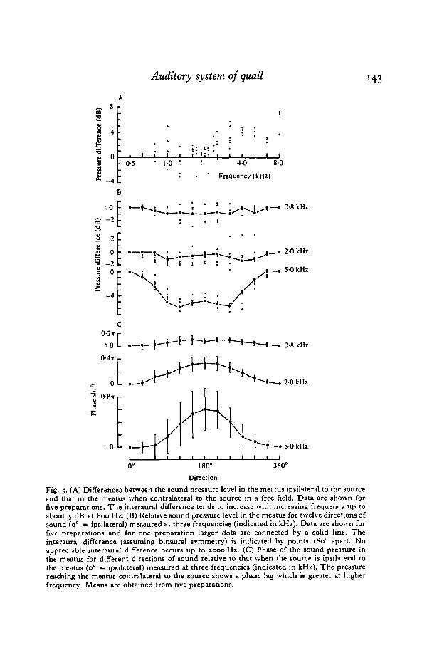
Fig. 5. (A) Differences between the sound pressure level in the meatus ipsilateral to the sourceand that in the meatus when contralateral to the source in a free field. Data are shown forfive preparations. The interaural difference tends to increase with increasing frequency up toabout 5 dB at 800 Hz. (B) Relative sound pressure level in the meatus for twelve directions ofsound (o° = ip8ilateral) measured at three frequencies (indicated in kHz). Data are shown forfive preparations and for one preparation larger dots are connected by a solid line. Theinteraural difference (assuming binaural symmetry) is indicated by points 1800 apart. Noappreciable interaural difference occurs up to 2000 Hz. (C) Phase of the sound pressure inthe meatus for different directions of sound relative to that when the source is ipsilateral tothe meatus (0° = ipsilateral) measured at three frequencies (indicated in kHz). The pressurereaching the meatus contralateral to the source shows a phase lag which is greater at higherfrequency. Means are obtained from five preparations.

144 K. G. HILL AND OTHERS
Frequency (kHz)
-20
Fig. 6. Sound pressure measured inside the interaural cavity in the free field: dots, pressurebehind the tympanum ipsilateral to the source relative to the ambient field; triangles, pressurebehind the tympanum contralateral to the source relative to the pressure in the adjacentmeatus. At most frequencies in the range 500-6300 Hz, sound pressures on each side of thetympany are within about 6 dB.
ablated. Fig. 4 A shows the difference between the sound pressure levels at one sideof the interaural cavity for sound presented at the ipsilateral and contralateral meatus.From 500 to 5000 Hz, attenuation of sound across the interaural cavity is within5 dB, and it is within 3 dB from 1000 to 5000 Hz. Slight positive gain between2500 and 5000 Hz suggests standing waves in the cavity. At the frequencies above5000 Hz, attenuation in the cavity sharply increases. The phase shift across the inter-aural cavity is shown in Fig. 4B. Over most of the frequency range, the phase shiftoscillates around zero. Above 3150 Hz a sharply increased phase shift is evident.
Sound pressures in the auditory system in a free field
The sound pressure in the meatus in the free field, when the sound source is atdifferent directions in the horizontal plane, is described in Fig. 5. The differencebetween the pressure levels measured in the meatus for ipsilateral and contralateralpresentation is shown in Fig. 5 A. Results for five preparations are plotted togetherand indicate some scatter. The attenuation of the sound pressure reaching the contra-lateral meatus is greater at higher frequencies, however, it reaches only about 5 dBby 8000 Hz. In Fig. 5 B, results for the same five preparations are plotted togetherand show the relative sound pressure in the meatus for each direction of the sourcefor three frequencies. Up to 2-0 kHz, there is no consistent reduction of pressureon the contralateral side. At 5-0 kHz the pressure in the contralateral meatus isreduced by about 5 dB. The phase of the pressure in the meatus also changes withthe direction of the source. The phase in the meatus for each direction relative to thephase when the source is ipsilateral is shown for three frequencies in Fig. 5 C. Whenthe source is shifted from the ipsilateral direction (0°), there is a phase delay whichreaches a maximum when the source is at or near the contralateral direction, i.e.when the path length from the loudspeaker to the microphone has been increased by

Auditory system of quail 145
0-8ir
0-4*
0-5 10 20 4-0 80
0-8*
3 °-0-4ir
0 8ir
0-4ir
"A
0-5 10 20Frequency (kHz)
40 80
Fig. 7. (A) Phase of the sound pressure behind the tympanum ipsilateral to the source relativeto that in the ipsilateral meatus in the free field. The phase shift across the ipsilateral tympanumsteadily increases with increasing frequency and crosses w/2 in the region of 1760 Hz. At highfrequencies, reversion to smaller observed phase differences are interpreted as phase shiftsgreater than 2»r. (B) Phase shift across the tympanum contralateral to the source in the freefield. The comparatively small difference between the phase of the internal and external soundpressures at the contralateral tympanum leads to the conclusion that the effective drivingpressure would be relatively diminished (see text) and is consistent with a diminished vibrationresponse at the contraloteral tympanum. (C) Difference between the phase ofthe pressurebehind the tympanum contralateral to thesource and that of the pressure in the meatusipsilateral to the source, i.e. the phase shift through the auditory system to the inside of thecontralateral tympanum. The dashed line shows the calculated phase lag to a sound pressurewave travelling 25 cm (approximate distance between the ears) around the head. When thesource is lateral, the effective phase shift imparted to the pressure reaching the inner surfaceof the contralateral tympanum appears to be matched over a wide frequency range to the phaseshift observed in a wave reaching the outer surface of the contralateral tympanum.
the distance around the head. At higher sound frequencies, the extent of the phasedelay is progressively greater when the source is contralateral to the microphone, i.e.the extra path length around the head is a greater proportion of a wavelength athigher sound frequencies. Phase delays measured in the contralateral meatus atdifferent frequencies, of which only three are illustrated in Fig. 5 C, agree well withphase delays expected in a wave travelling the extra distance around the head (seeFig. 7C).

146 K. G. HILL AND OTHERS
Fig. 8. The calculated effective driving pressure at the tympanum (see text) as a function of thedirection of the sound source, plotted for several frequencies (indicated in kHz) on polarcoordinates. Effective pressures were calculated using the measured amplitude and phaseof the inner and outer sound pressures at the tympanum. At frequencies above 1600 Hz, theeffective pressure on the tympanum is reduced when the source is on the contralateral siderelative to that when the source is ipsilateral. Note that in some cases the maximum interauraldifference in sensitivity to be deduced from these plots occurs when the source is slightlyanterior to the lateral direction; also, that interaural differences in sensitivity of about 10-20 dBare predicted.
Sound pressure developed inside the head cavity just behind the tympanum, rela-tive to the strength of the free field, is shown in Fig. 6. For frequencies from 800 to3150 Hz and the source located ipsilateral to the position of the microphone in theinteraural cavity, the measured pressure is within 6 dB of the ambient sound field.When the source is contralateral to the microphone, the pressure inside the tympanumis within 8 dB of the pressure in the meatus from 800 to 6300 Hz.
The difference between the phases of the pressure on the external surface and on theinternal surface of the tympanum ipsilateral to the source is shown in Fig. 7 A. In the*

Auditory system of quail
free field, the phase difference across the ipsilateral tympanum increases from a lowvalue at 800 Hz, it crosses 77/2 at 1725 Hz and increases towards IT at 3150 Hz. Athigher frequencies, the phase difference across the ipsilateral tympanum rapidlyincreases further and (presumably) crosses 2TT. The phase difference across thetympanum contralateral to the source in the free field is shown in Fig. 7B. It isdistinctly different to that at the ipsilateral tympanum. Over the frequency range800-6300 Hz, the phase difference across the contralateral tympanum remains com-paratively small and it is within 77/4. In Fig. 7C, the phase of the internal pressurenear the tympanum contralateral to the source is plotted relative to the phase of thepressure at the entrance to the meatus ipsilateral to the source, indicating the phaseshift in the sound transmission through the auditory system to the inside of thecontralateral tympanum. For comparison, the dashed curve in Fig. 7C shows theexpected phase shift, as a function of frequency, in a sound wave propagated 2-5 cmthrough air, i.e. the extra distance around the head from the ipsilateral side to thecontralateral meatus. Over the range 500-8000 Hz the net phase shift via the paththrough the head approximates to that expected in a wave travelling around the head.
DISCUSSION
Free measurements of sound pressure in the auditory meatus of the quail, forfrequencies up to 8000 Hz, show that the pressure reaching the outside surface of thetympanum contralateral to a sound source is attenuated by up to about 5 dB relativeto that at the ipsilateral tympanum. In the range 800-3150 Hz, which covers most ofthe spectrum of male vocalizations in C. c.japonica (unpublished results), attenuationat the contralateral tympanum is only 0-3 dB. In addition, however, sound pressuredevelops at the inside surface of each tympanum and the amplitude of the internalpressure is within about 8 dB of the pressure in the meatus over the frequency range800-6300 Hz. It is clear, therefore, that the auditory tympana in the quail, and inother birds where similar acoustic conditions may apply, respond to the influence ofsound pressure on both sides and must be considered as pressure-gradient receivers.The amplitude of the tympanal vibration and the response of auditory receptors willdepend, therefore, on the vector sum of the forces on the tympanum arising from theinternal and external sound pressures. The effective driving pressure on an auditorytympanum, expressed in dB, sharply declines when the phase difference betweeninteracting pressures of similar amplitude is small (see Nocke, 1975; Hill & Boyan,1977; Miller, 1977). Since a balanced, asymmetrical pressure-gradient receiver (sensuMichelsen & Nocke, 1974) has substantial inherent directionality, a pair of suchreceivers operating reciprocally can provide a significant interaural difference ineffective intensity. For the quail, this would be a far more reliable cue for sound locali-zation than the traditional cues of interaural time difference of tens of microsecondsor intensity difference external to the tympanum due to head shadowing, which isonly about 1-3 dB up to 3150 Hz. In the quail, the development of a reciprocal pairof asymmetrical, pressure-gradient receivers results from internal acoustic couplingof the auditory tympana via the cavity through the floor of the skull. This basis fordirectional hearing appears to be an evolutionary strategy employed by most if notall small animals communicating with sounds of wavelength much greater than body

148 K- G. HILL AND OTHERS
size (from anatomical and physiological studies of insects and anatomical considera-tions of frogs, reptiles and birds).
Measurements of sound transmission through the auditory system of the quailpermit some qualitative characterization and a calculation to a first approximationof the expected directionality of the vibration response of the auditory tympana. Themeatus is essentially a short tube extending almost vertically upwards from thetympanum. It has the effect of placing the entry port of sound into the auditorysystem much nearer the centre of the side of the head than would be the case if theventrally placed tympana were exposed more directly. Hence, the meatus may serveto maximize the phase delay to the sound wave travelling around the head to thecontralateral ear (the significance of which is apparent below). Acoustically, themeatus may constitute a small mass of confined air that is oscillated back and forthwith the tympanum and which has some damping effect due to friction at the walls ofthe tube. Its effect on the passage of sound to the tympanum (Fig. 2) is to increaseattenuation at slightly more than 6 dB per octave up to 5000 Hz. The factors re-sponsible for this filtering effect are unknown.
The auditory tympanum is coupled to the columella and to the cochlea. The soundpressure developed behind the tympanum in the interaural cavity, when sound isapplied to only one meatus, suggests the manner in which the tympanum behaves asa part of the auditory mechanism. At low frequency (500 Hz) its response is relativelyweak and the phase of the pressure behind the tympanum suggests that it movesnearly in phase with the incident pressure (Fig. 3). As the frequency is increased, theresponse of the tympanum increases to a broad maximum at around 2000 Hz and itsdisplacement appears to lag the phase of the incident pressure by about 77/2. To thisstage, the inferred response of the tympanum is similar to that of a simple drivenoscillator having a highly damped resonance at 2000 Hz. At higher frequencies, theresponse declines only slightly and the phase lag appears to suddenly increase beyond27T. This behaviour, however, is not consistent with that of a simple driven oscillatorand may indicate effects on the tympanum due to its mechanical link with the re-ceptors and the complex interaural cavity.
The interaural cavity has some similarity with a low pass filter with a sharp cut offabove 5000 Hz. It introduces only small phase shifts to the pressure traversing thehead for frequencies up to 5000 Hz. At higher frequencies, where attenuation in theinteraural cavity increases, rapidly increasing phase shifts are observed.
When the bird is subjected to sound in a free field, the significance for directionalhearing of the characteristics of the auditory system becomes apparent. The pressuredeveloped inside the interaural cavity is substantially higher in the free field situationthan for unilateral input (compare Figs. 2 and 6). This is due to sound input via twoports (both tympana) when the source is on the medial axis, or to stiffening of thecontralateral tympanum (see below) when the source is located laterally. These condi-tions do not apply when sound is applied to only one meatus. In steady state conditions,each tympanum is acted upon by an internal and an external sound pressure whichare of similar amplitude at some frequencies over a wide frequency range (Fig. 6).Furthermore, the external and internal pressures at the tympanum ipsilateral to thesource differ in phase by more than 77/6 for frequencies above 1200 Hz. In contrast,external and internal sound pressures at the contralateral tympanum differ in phase

Auditory system of quail 149
by less than 77/6 for each frequency in the range 800-5000 Hz (Fig. 7). The effectivepressure causing the tympanum to vibrate is indicated by the instantaneous differencebetween the interacting pressures. Using the measured amplitude and phase of theinternal and external sound pressures for different locations of the sound source, wehave calculated the amplitude of the net pressure on the auditory tympanum inindividual preparations using the equation
Pnei.sin (a>t + <j)') = Pi.s'm (ot —P2.sin (ait+ (/>),
where t and a> refer to time and angular frequency respectively, P1 and P2 representthe relative absolute amplitudes of the measured internal and external pressures atthe tympanum and </> represents the phase difference between them. An example ofthe relative amplitude of Pn e t calculated for different directions and at differentfrequencies of sound and then expressed in dB, is shown on polar coordinates inFig. 8. The calculated effective pressure on the tympanum varies with the directionof the source over a wide frequency range and at some frequencies it shows significantreduction when sound is from the contralateral direction. There is a clear trend ofgreater effective pressure on the ipsilateral side, and reduced effective pressure onthe contralateral side. From two ears acting reciprocally in this manner, unambiguousdirectional information would be available to the central nervous system due to aneffective interaural intensity difference for lateral sound of from 10 to 20 dB.
The essential features of the auditory system in the quail responsible for thisdirectionality of the tympana are: (1) the interaural head cavity which conducts soundbetween the ears so that pressures of similar amplitude exist at the outer and innersurfaces of each tympanum and (2) the net phase shift imparted to the pressure reach-ing the inside of the tympanum when it is contralateral to a sound source so that theinternal pressure is at a similar phase to the external pressure, which has travelled theextra distance around the head. The similarity of the net phase shift through the headand phase shift around the head (Fig. 7C) depends on a maximum external path ofabout 2-5 cm when the source is lateral. Maximizing this distance may be one functionof the meatus.
A similar degree of directional sensitivity in the response of the auditory tympanumcan be expected in other small vertebrates in which acoustic conditions at the tym-panum are similar to those in the quail, e.g. frogs (Strother, 1959; Chung, Pettigrew& Anson, 1978), caimans (Wever & Vernon, 1957) and lizards, which also have theappropriate anatomy. Chung et al. (1978) claimed that the buccal cavity of the frog,to which the eardrums are coupled, shows strong resonance at the frequency of thespecies' call. They also tentatively suggested, however, that the directional responseof the frog tympanum depended upon the pressure gradient principle. The frogauditory system is analogous to that of the bladder cicada Cystosoma saundersii (twoauditory tympana coupled to a common air cavity) and in both cases, males propagatenarrowly tuned acoustic signals utilizing their resonant air cavities (the frog vocalsac - Martin, 1972; the cicada abdomen-Young & Hill, 1977; Fletcher & Hill, 1978).Because of resonance in the air cavity when exposed to sound at the frequency of thespecies' call, the pressure gradient at the tympanum of the cicada does not producea directional response (Fletcher & Hill, 1978), and the male cicada has non-directionaJRearing to the species' song frequency (Young & Hill, 1977). The incompatibility

150 Auditory system of quail
between the strong resonance in the interaural cavity and directionality in the respons^of the tympana suggests that the resonance in the frog's buccal cavity be re-evaluated.
This physical mechanism for the directional sensitivity of the quail auditory systemhas also been adopted by insects that communicate with comparatively low frequencysounds. Not surprisingly, it is also a mechanism for directionally sensitive micro-phones. Payne (1971) noted that the ears of barn owls are connected by a cavity inthe head which should permit sound transference from one ear to the other. However,he restricted his considerations with regard to directional hearing to sound pressureentering the meatus as a function of direction and did not consider the pressure-gradient principle. Since the feathers surrounding the external opening of the meatus inthe owl may have an acoustic function and furthermore, since barn owls appear to relyon comparatively high frequencies (5000-7000 Hz) for acoustic location (Konishi, 1973),the exact mechanism of directional hearing in owls may differ from the simple modelpresented here (see also Coles et al. 1980). At 3 kHz sound frequency, Schwartzkopff(1962) found that simultaneous cochlear microphonic recording in the two ears ofthe owl Asio otus indicated a difference of about 10 dB between the effective soundpressures at each tympanum. These experiments did not examine the role of the headcavity in the directionality of the ears. Some owls, however, appear to have otherspecializations for high directional acuity which are not general to the auditorysystems of birds, so modification in owls to the basic pressure-gradient system mightbe expected. Schwartzkopff (1952) noted the possibility that the auditory tympana infinches would function as pressure-gradient receivers as a result of sound transmissionthrough the interaural cavity. He specifically tested for the amount of sound trans-mission between the ears and concluded that the internal sound pressure at eachtympanum would be too low to effect the response of the tympanum. Since hismeasurements were of the cochlear microphonic and not directly of the soundpressure we cannot account for the difference between his and our conclusions. Inthe following paper (Coles et al. 1980), the directional sensitivity of the cochlearmicrophonic in the quail is shown to depend on sound transmission across the inter-aural cavity.
K. G. Hill gratefully acknowledges receipt of a Nuffield Foundation TravellingFellowship during the period of this work. R. B. Coles is an Alexander von HumboldtFellow and received additional support from a von Humboldt Stiftung 'Eurosti-pendium', which is greatly appreciated. We thank Professor N. H. Fletcher forhelpful discussions and criticism of the manuscript.
REFERENCES
CHUNO, S-H., PETTIGREW, A. & ANSON, M. (1978). Dynamics of the amphibian middle ear. Nature,Land. 272, 142-147.
COLES, R. B., LEWIS, D. B., HILL, K. G., HUTCHINGS, M. E. & GOWER, D. M. (1980). Directionalhearing in the Japanese quail (Coturnix coturnix Japonica). II. Cochlear physiology. J. exp. BM.86. I53-I7°-
FLETCHER, N. H. & HILL, K. G. (1978). Acoustics of sound production and of hearing in the bladdercicada Cystoma saundersii (Westwood). J. exp. Biol. 72, 43—55.
HILL, K. G. & BOYAN, G. S. (1977). Sensitivity to frequency and direction of sound in the auditorysystem of crickets (Gryllidae). J. comp. Physiol. 121, 79-97.

Auditory system of quail i ^ i
KONISHI, M. (1973). Locatable and nonlocatable acoustic signals for barn owls. Am. Nat. 107, 775-785.LEWIS, D. B. ( I 974). The physiology of the tettigoniid ear. IV. A new hypothesis for acoustic orientation
behaviour. J. exp. Biol. 60, 861-869.MARTIN, W. F. (1972). Evolution of vocal behaviour in the genus Bufo. In Evolution of the Genus Bufo.
(ed. W. F. Blair). Austin: University of Texas Press.MICHELSEN, A. (1971). The physiology of the locust ear. III. Acoustical properties of the intact ear.
Z. vergl. Pkysiol. 71, 102-128.MICHELSEN, A. & NOCKE, H. (1974). Biophysical aspects of sound communication in insects. Adv.
Insect Physiol. io, 247-296.MILLER, L. A. (1977). Directional hearing in the locust Schistocerca gregaria Forskal (Acrididae,
Orthoptera). J. comp. Physiol. 119, 85-98.NOCKE, H. (1975). Physical and physiological properties of the tettigoniid ('grasshopper') ear. J. comp.
Physiol. 100, 25-57.PAYNE, R. S. (1971). Acoustic location of prey by barn owls (Tyto alba). J. exp. Biol. 54, 535-573.SCHWARTZKOPFF, J. (1952). Untersuchungen ilber die Arbeitsweise des Mittelohres and das Richtungs-
hSren der SingvOgel unter Venvendung von Cochlea-Potentialen. Z. vetgl. Physiol. 34, 46-68.SCHWARTZKOPFF, J. (1962). Zur Frage des Richtungshorens von Eulen (Striges). Z. vergl. Physiol. 45,
570-580.STROTHER, W. F. (1959). The electrical response of the auditory mechanism in the bullfrog (Rana
catesbeiana). J. comp. Physiol. Psychol. 53, 157-162.WEVER, E. G. & VERNON, J. A. (1957). Auditory responses in the spectacled caiman. J. cell. comp. Physiol.
50. 333-339-YOUNG, D. & HILL, K. G. (1977). Structure and function of the auditory system of the cicada Cysto-
soma saundersii. J. comp. Physiol. 117, 23—45.
