directed acoustic shearography or what you cant see can hurt you
TRANSCRIPT

DirectedAcousticShearography
-or-
What youcan not see
CAN hurt youRussell Kurtz, PHD
Chief Scientist, RANscitechApril 2010
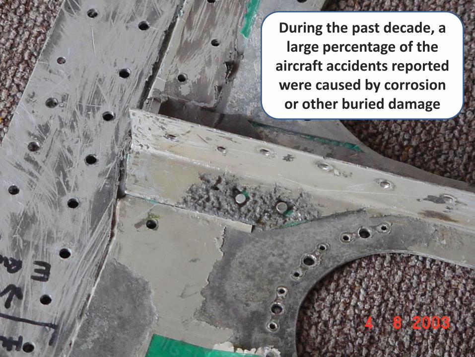
During the past decade, a large percentage of the
aircraft accidents reported were caused by corrosion or other buried damage

LAYERS OF METAL
When these defects occur in modern materials made up of several layers, detection can be difficult and expensive.
Defect Disassembly itself causes damage and some composites can’t be disassembled at all.

Aloha Airlines Flight 243, April 28, 1988
It is , therefore, critical to develop a Nondestructive Evaluation (NDE) Technology that can find
these buried defects, corrosion, or damage spots rapidly, accurately, and efficiently.
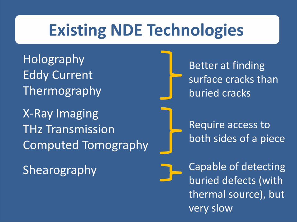
HolographyEddy CurrentThermography
Existing NDE Technologies
Better at finding surface cracks than buried cracks
X-Ray ImagingTHz TransmissionComputed Tomography
Require access to both sides of a piece
Shearography Capable of detecting buried defects (with thermal source), but very slow

FAST
Directed Acoustic Shearography
Shearography using an acoustic stress source is the basis of
Directed Acoustic Shearography

THEORY
RAN Science and Technology LLC
Presentation to SPIEApril 2010
Orlando, Floridaby
Russell Kurtz, PHDChief Scientist
RAN Science & Technology
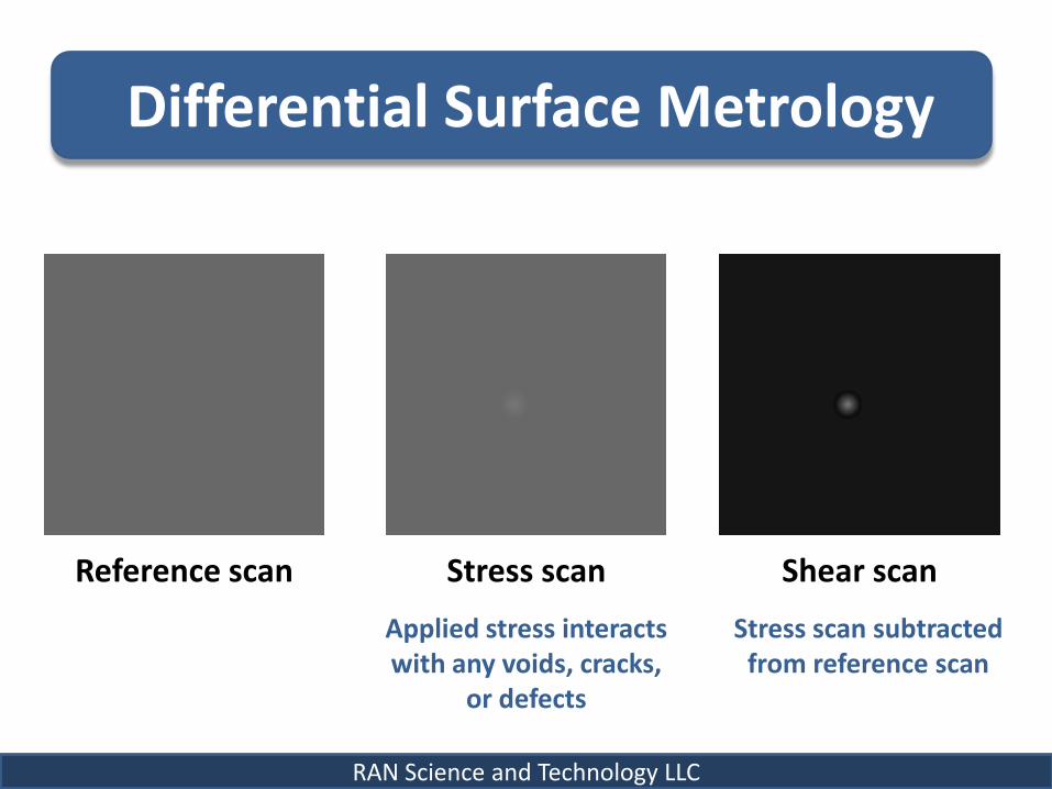
Differential Surface Metrology
Reference scan Stress scan Shear scan
RAN Science and Technology LLC
Applied stress interacts with any voids, cracks,
or defects
Stress scan subtracted from reference scan

Shearography Stress Methods
Apply Heat0.3-in. auto part
Acoustic Signal
RAN Science and Technology LLC
Takes between 3 and 60 seconds
for thermal equilibrium to be
reached
Stress propagates through depth
virtually instantly
However, a typical spherical wave is not a good choice
as its intensity decreases as fast as the depth squared

Directed Acoustic Shearography
An acoustic signal could be a good source of stress
IFit could be focused.
RAN Science and Technology LLC
This can be accomplished with a
Phased Array Acoustic Transducer (PA)

The PA
A 2D array of transducers whose relative phase and intensity can be controlled
RAN Science and Technology LLC
Able to focus the signal down to a narrow spot, or create a collimated beam of acoustic intensity
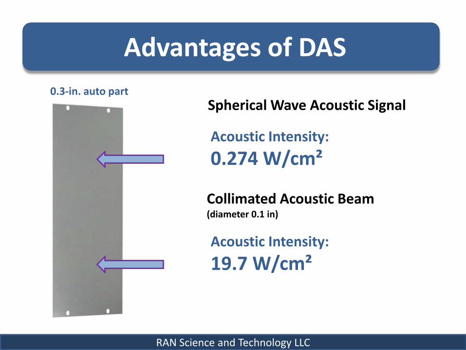
Advantages of DAS
0.3-in. auto part
Spherical Wave Acoustic Signal
RAN Science and Technology LLC
Acoustic Intensity:
0.274 W/cm²
Collimated Acoustic Beam(diameter 0.1 in)
Acoustic Intensity:
19.7 W/cm²
DAS Also Improves Resolution
For accurate determination of defect depth, a minimum of four scans must be performed at
different angles. The exact number depends on the thickness of the material.
RAN Science and Technology LLC

MODELING & EXPERIMENT
RAN Science and Technology LLC
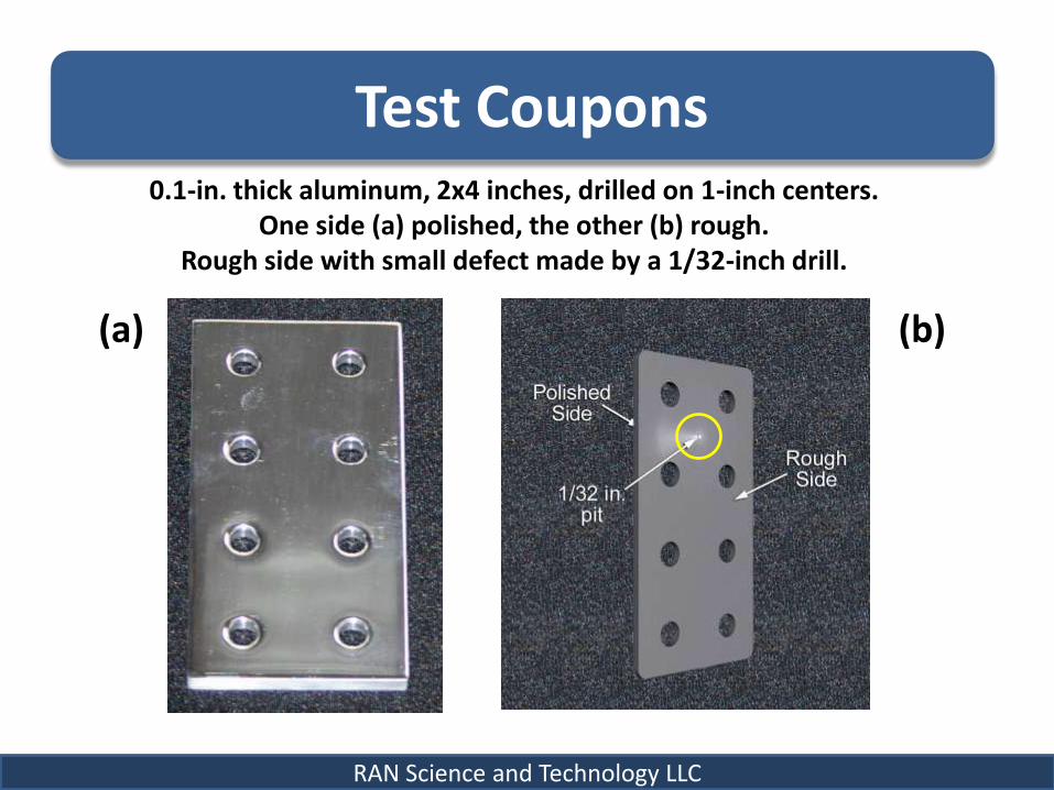
Test Coupons0.1-in. thick aluminum, 2x4 inches, drilled on 1-inch centers.
One side (a) polished, the other (b) rough. Rough side with small defect made by a 1/32-inch drill.
RAN Science and Technology LLC
(a) (b)

Finite Element ModelingWe found that a 0.1-in. diameter collimated beam,
with an acoustic power of 125mW, would induce a surface deflectionof >7.5 µm if it encountered the 1/32-in. defect.
RAN Science and Technology LLC
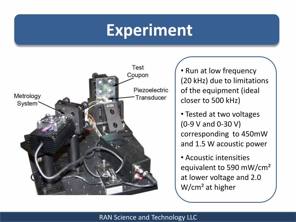
Experiment
RAN Science and Technology LLC
• Run at low frequency (20 kHz) due to limitations of the equipment (ideal closer to 500 kHz)
• Tested at two voltages (0-9 V and 0-30 V) corresponding to 450mW and 1.5 W acoustic power
• Acoustic intensities equivalent to 590 mW/cm² at lower voltage and 2.0 W/cm² at higher

Results
RAN Science and Technology LLC
2.0
1.5
1.0
0.5
0.0
–0.5-0.4 -0.2 0.0 0.2 0.4
x-Position (in.)
Dif
fere
nce
(μ
m)
y-Po
siti
on
(in
.)
0.4
0.2
0.0
-0.2
-0.4
-0.4 -0.2 0.0 0.2 0.4x-Position (in.)
y-Po
siti
on
(in
.)
0.4
0.2
0.0
-0.2
-0.4
6
4
2
0
-2
Dif
fere
nce
(μ
m)
Net deflection increase 2.9 µm with 9 V
Net deflection increase 10 µm with 30 V

Summary
We found it!
RAN Science and Technology LLC
The concept of Directed
Acoustic Shearography
has been proven

Still keep your eye out for alligators
Conclusion