direct torque control of induction motor fed by three...
TRANSCRIPT

AMSE JOURNALS-AMSE IIETA publication-2017-Series: Advances C; Vol. 72; N°4; pp 248-265
Submitted March 2017; Revised June 17, 2017, Accepted July 25, 2017
Direct Torque Control of Induction Motor Fed by Three-level
Inverter Using Fuzzy Logic
BERRABAH Fouad*, CHEBABHI Ali***, ZEGHLACHE Samir*, SAAD Salah**
*Department of Electrical Engineering, University of M’sila, Algeria, BP-166 University of M’Sila
28000 ([email protected])
** Laboratory Systèmes Electromécaniques (LSELM), University of Annaba, Algeria
***ICEPS Laboratory (Intelligent Control & Electrical Power Systems). Djillali Liabes University
of Sidi Bel-Abbes Algeria
***Faculty of Science and Technology, University of Bordj Bou Arreridj, Algeria
Abstract
The present paper describes the direct torque sensor less speed control of induction motor fed
by three-level voltage source inverter. Inverter switches control is based on fuzzy logic control.
Compared to conventional direct torque control (DTC), hysteresis controllers, flux position and
voltage vector selection table are replaced by fuzzy logic blocks to realize a DTC-fuzzy control.
The obtained results have showed high speed performance, reduced torque and flux fluctuations
when the proposed DTC-fuzzy strategy is used for the control of three-level voltage source
inverter associated with induction machine.
Keywords
DTC, Fuzzy logic, DTC- FLC, Three-level NPC Inverter.
1. Introduction
Asynchronous motors particularly induction motors are widely used in variable speed drive
systems due to their low cost and construction simplicity. The direct torque control technique
(DTC) introduced in 1985 is an attractive approach due to its effectiveness and implementation
248

simplicity as demonstrated by several studies [1-6]. Therefore, this technique enables the control
variables computation (stator flux and electromagnetic torque) from stator current measurements
without using mechanical sensor.
In DTC structure, the induction motor fed by voltage source inverter is a hybrid dynamic
system in which the continuous part is the induction machine and the discrete part is the voltage
source inverter. In this paper, the application of DTC-fuzzy strategy concept is extended to a
three-level voltage source inverter feeding asynchronous motor. This extension concerns the
generation of voltage vector applied to the machine according to the number of voltage levels
generated by the three-level inverter [3, 5, 7, 8]. This new direct torque control approach
improves controller switching strategy of flux and torque of induction machine fed by a
three-level NPC inverter.
Recently, optimization of DTC algorithms based on two-level inverter was studied in several
papers [5, 7]. However, the main motivation of the present paper is to improve ac motors
performances using a control approach based on so-called DTC-fuzzy control. Hysteresis blocks
of torque and flux as well as the switching table of the conventional system are replaced by a set
of fuzzy system. Three-level voltage source inverter (VSI) switching laws are determined by
linguistic rules of fuzzy decision table and the speed is controlled by a conventional PI controller.
This control structure reduces torque and flux fluctuations. In this paper, the DTC technique basic
principle is explained and recalled [9-13], then, the model of three-level voltage inverter is
presented. Finally, the DTC-fuzzy control technique is described, system performances are
analyzed, and a conclusion is given.
The developed algorithm is validated by computer simulation tests using Matlab-Simulink
environment. The obtained results have showed high speed performance, torque and flux
reduced fluctuations when the proposed DTC-FLC strategy is employed for the control of
three-level voltage source inverter associated with asynchronous machine.
2. Theoretical development of direct torque control
2.1 Electromagnetic torque control
Electromagnetic torque ( is expressed in function of stator and rotor fluxes as
follows [1]:
(1)
K is a constant depending on machine parameters.
249
(2)
Stator and rotor fluxes can be expressed as follows:
(3)
and are stator and rotor fluxes modules respectively at t = 0. and are stator
and rotor
Substituting stator and rotor fluxes expressed in Eq.3 in the electromagnetic torque equation
given in Eq.1.
Knowing that the control law desires to maintain the stator flux close to its reference value
the following expression is obtained [5]:
(4)
(5)
When applying ''active'' voltage vector so that, the positions and rotor speeds and stator
fluxes are modified as follows:
(6)
Where:
(7)
= Synchronous speed
The expression above is the stator vector speed variation, similarly the rotor flux can be
written as follows:
(8)
with:
250
If the evolution of the rotor flux is considered very slow compared to the stator flux, the
implementation of active voltage vectors Δφr and Δθr are still zero, and thus:
(9)
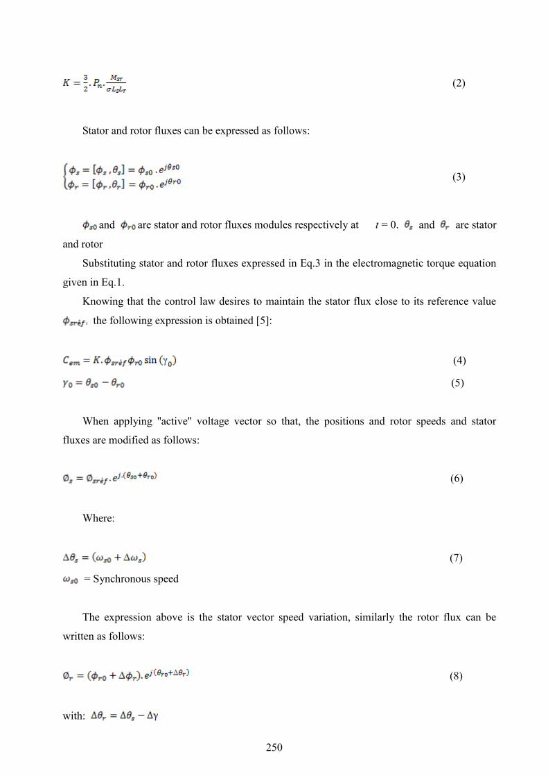
The torque control depends directly on the stator flux vector rotation control. Fig.1,
illustrates the evolution of the electromagnetic torque in the case of the application of two voltage
vectors that are changing the stator flux in opposite direction of rotation. The trigonometric
rotation direction is considered as the positive direction.
Figure 1. Electromagnetic torque evolution for rotational speed variation.
2.2 Stator flux vector control
The stator flux modulus evolution law is determined from the differential equation of the
stator flux expressed in fixed frame .
(10)
= Stator voltage
= Rotor resistance
= Stator current
In the interval [0, ], the term can be simplified and equation (10) can be written as
follows [2].
(11)
251

Te = Sampling period
It should be noted that the extremity of the stator flux vector is moving along a straight line
to that of collinear axis to the voltage vector imposed by the inverter to the machine Fig. 2 [1].
Figure 2. Statorique flux variation.
The stator flux vector displacement is achieved by successive application of voltage vectors
fed by the inverter. Furthermore, according to the applied voltage vector, one can act on the value
of the stator flux modulus as shown in Fig.2.
Thus, according to the choice of the stator voltage vector on successive intervals of the
sampling period Te duration, can be tacked at the extremity of the stator flux vector a trajectory
almost circular and maintain the flux amplitude close to a constant reference value. This is
illustrated by Fig.3 which corresponds to an example of asynchronous machine fed by two-level
voltage source inverter. The stator flux is maintained in a hysteresis band centered on the
reference flux [4].
Figure 3. Statorique flux trajectory.
3. Three-level voltage inverter operation and modeling
The technological progress in induction machines variable speed control has advantaged the
Increasing Deceasing
252

use of three-level inverters. As discussed previously, the increase in the number of levels proves
to be a better solution for high power drives.
The inverter consists of switching cells usually transistors or GTO for high power. The
association of asynchronous machine and three-level NPC voltage source inverter (VSI)
controlled by DTC algorithms is presented and studied. The midpoint inverter is the most
appropriate because the output voltages and output currents present less harmonic distortion than
that obtained with a classical inverter [4].
The power circuit of three-level inverter called Neutral Point Clamped (NPC) is given in the
Fig.4. It is a structure with three-level voltage. Each inverter leg consists of four switches;
, , , .
The mathematical model of this inverter is given by the following matrix:
(12)
Each inverter leg has three switching states as illustrated in Table I.
, , : Phase-to neutral voltages
: The logical switching state
: dc voltage
Table 1. Three-level inverter switching states.
Switches state
1 1 0 0
0 1 1 0
0 0 1 1 0
Table 2. Voltage vectors associated to the switching states.
Voltage vector Symbol
ZVV
MVV
253

LVV
USVV
LSVV
Figure 4. Three-level NPC voltage source inverter (VSI).
Table 2 shows 27 switching states of the inverter. According to these states 19 voltage
vectors with different modulus are obtained [3-4].
Figure 5. Output voltage vector representation.
Fig.5 shows that these voltage vectors are classified into four groups and according to their
modulus it can be defined as follows:
• ZVV group, zero voltage vector
• SVV group, small voltage vectors ( , , , , , )
• MVV group, medium voltage vectors ( , , , , , )
• LVV group, large voltage vectors ( , , , , , )
254

Zero vector has three switching states, small vectors have two switching states (USVV,
LSVV), medium and large vectors have only one switching state as example voltage vector V2
corresponds to PNN state. Logical variables associated with the latter are [3]:
(13)
In terms of inverter control, this topology offers the following advantages:
• High number of degrees of freedom compared to two-level inverter,
• Reduced output current ripple,
• Remarkable property of interlocking hexagons, concept of two- level three-phase cell.
4. Direct torque control with fuzzy logic control (DTC-Fuzzy)
In the conventional direct torque control, the use of torque and flux errors allows to choose
directly the switching state without distinguishing between a very large or relatively small error.
Furthermore, the selected switching state for a large error that occurs during startup or during
torque and flux set points change is the same as in normal operation. This obviously implies poor
response.
System performance can be improved if the voltage vector is selected according to the value
of torque and flux error as well as the flux position in the space of its evolution.
Three-level
NPC voltage
source inverter
MASDTC-FLCinS
si
si
Flux and
Torque
Estimation
ˆs
emC
+
-
+
-
emC
*
emC
ˆs
*
s
( )emC
( )s
ˆs
ˆs
123si
Concordia
TransformationPosition
Secteur N
*PI
Figure 6. DTC-Fuzzy control scheme.
255

This error function is the difference between parameter computed from the information
provided by the control and the equivalent parameter determined from measurements. The
principle of fuzzy logic employing fuzzy concept can be applied to many problems when
handling imprecise and indistinct parameters. It will be seen later, the advantage of this mode of
analysis from the expertise rules defined by the inputs. The principle of DTC-FLC is illustrated in
Fig.6.
A. Fuzzy logic control development
The speech universe of the first input variable is divided into three fuzzy sets:
• Flux error is positive P
• Flux error is zero Z
• Flux error is negative N
The trapezoidal membership functions are chosen for the variables P, N and triangular for Z
set Fig.7.
Figure 7. Membership function of flux error .
The second input is the torque error . Its speech universe is divided into five fuzzy sets:
• Torque error is positive large PL
• Torque error is positive small PS
• Torque error is zero ZE
• Torque error is negative small, NS
• Torque error is negative large, NL
Triangular membership functions are chosen for the sets PS, ZE and NS and trapezoidal
membership functions for the sets PL and NL, Fig.8.
Figure 8. Membership function of torque error .
256

The third input variable is the flux position in the stator frame. The angle is given by:
(14)
Speech universe of this variable is divided into 12 fuzzy sets ( to ) with membership
function presented in Fig.9.
Figure 9. Position membership function.
Decomposing into six sub-outputs representing three-level inverter six switches, the speech
universe of each output is divided into two fuzzy sets (zero and one) with its membership
functions are chosen by forms of type presented in Fig.10 [10].
Figure 10. Membership function of switches switching states
B. Fuzzy controller structure for three-level inverter
The control rules are expressed in function of input and output variables as follows:
Ri: if is N and is NL and is thus, is zero is zero is zero is
zero is one is one.
257

Figure 11. Fuzzy controller structure for three-level inverter.
Table 3. Switching table.
NL NS ZE PS PL NL NS ZE PS PL
P 17 18 0 3 5 P 2 18 0 6 5
Z 13 0 0 4 4 Z 16 0 0 7 4
N 14 15 0 6 8 N 17 15 0 9 8
NL NS ZE PS PL NL NS ZE PS PL
P 2 3 0 6 8 Z 5 3 0 9 8
Z 16 0 0 7 7 N 1 0 0 10 7
N 17 18 0 9 11 P 2 18 0 12 11
NL NS ZE PS PL NL NS ZE PS PL
P 5 6 0 9 11 P 8 6 0 12 11
Z 1 0 0 10 10 Z 4 0 0 13 10
N 2 3 0 12 14 N 5 3 0 15 14
NL NS ZE PS PL NL NS ZE PS PL
P 14 15 0 18 2 P 11 9 0 15 14
Z 10 0 0 1 1 Z 7 0 0 16 13
N 11 12 0 3 5 N 8 6 0 18 17
NL NS ZE PS PL NL NS ZE PS PL
P 8 9 0 12 14 P 14 12 0 18 17
Z 4 0 0 13 13 Z 10 0 0 1 16
N 5 6 0 15 17 N 11 9 0 3 2
258

NL NS ZE PS PL NL NS ZE PS PL
P 11 12 0 15 17 P 17 15 0 3 2
Z 7 0 0 16 16 Z 13 0 0 4 1
N 8 9 0 18 2 N 14 12 0 6 5
5. Adaptive estimation of speed with reference model (MRAS)
The estimation principle using this method is based on the comparison of values obtained by
two different ways, a computation which does not depend on the speed (reference model) and a
computation that depends on speed (adaptive model). This method is developed by Schauder,
known as Model Reference Adaptive System (MRAS) [14].
Figure 12. Estimation of asynchronous machine speed by MRAS technique.
6. Simulation and results
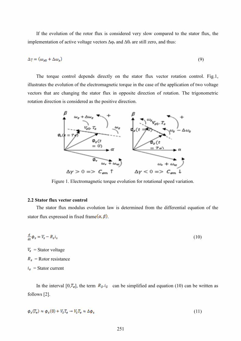
Simulation tests were conducted using the parameters illustrated in table 4. The results
shown in Fig.13 (a) and 13 (b) represent the behavior of DTC structure applied to 1.5 kW
asynchronous motor fed by three-level inverter for a switching table of five-level torque corrector
and three-level flux corrector in the classical and fuzzy case. Several operation characteristics
were studied, such as the starting response, steady-state response and some internal variables,
such as line current and voltage, stator flux, torque and speed, were viewed using Matlab
simulink Blocks.
Reference model
Adjustable
Model
Adaptation
Mechanism
Vs
Is ˆ
ref
ˆr
259

Table 4. Switching table.
Parameters Values
Voltage rating 220 / 380 (V)
Current rating 6.4 / 3.7 (A)
Motor power 1.5 (kW)
Number of pole pairs p = 2
Stator resistance per phase R s= 4.85 ( )
Rotor resistance per phase Rr = 3.805 ( )
Stator inductance Ls = 0.274 (H)
Rotor inductance Lr = 0.274 (H)
Mutual inductance Lm= 0.258 (H)
Moment of inertia J=0.031(Kg )
Speed rating N = 1420 (tr /min)
Friction Coefficient f r=0.000114(Kg )
Inverter dc voltage = 514 (V)
Torque rating C=10Nm
A. Classical DTC applied to asynchronous machine fed by two-level inverter
1 1 . 0 1 1 . 0 2 1 . 0 3 1 . 0 4 1 . 0 5 1 . 0 6 1 . 0 7 1 . 0 8 1 . 0 9 1 . 1- 5 0 0
- 4 0 0
- 3 0 0
- 2 0 0
- 1 0 0
0
1 0 0
2 0 0
3 0 0
4 0 0
5 0 0
T e m p s ( s )
te
ns
ion
V
sa
(V
)
Times(s)
saV
(V)
260
1 1 .0 2 1 .04 1 .06 1 .08 1 .1-0 .4
-0 .3
-0 .2
-0 .1
0
0 .1
0 .2
0 .3
Tem p s (s )
Co
up
le(N
.m)
0 0 .5 1 1 .5 2 2 .5-5
0
5
1 0
1 5
2 0
2 5
Te m ps (s )
Co
up
le(N
.m)
C r
C em
Times(s)Times(s)
emC
(Nm
)
emC
(Nm
)
0 0.5 1 1.5 2 2.50
50
100
130
150
Temps(s)
Vitesse(r
ad/s
)
1.4 1.6 1.8 2 2.2122
124
126
128
130
132
Temps(s)
Vitesse(r
ad/s
)
Wref
W
Times(s)Times(s)
(rad
)
(rad
)
0 0.5 1 1.5 2 2.5-15
-10
-5
0
5
10
15
20
Tem ps (s )
Is-a
lph
a(A
)
1 1.02 1.04 1.06 1.08 1.1-5
0
5
Tem ps (s )
Is-a
lph
a(A
)
Times(s)Times(s)
sαI(A
)
sαI
0 0.5 1 1.5 2 2.50
0.2
0.4
0.6
0.8
1
1.207
1.4
Temps(s)
Flu
x s
tato
rique(W
eb)
-1.207 -0.8 -0.5 0 0.5 0.8 1.207
-1.207
-0.8
-0.5
0
0.5
0.8
1.207
phis-alpha
phis
-bitta
Times(s)
Sta
tor
Flu
x(
Web
)
Figure 13(a). Waveforms obtained by classical DTC: phase to neutral voltages, torque, speed,
current, stator flux.
261

B. DTC-Fuzzy technique applied to asynchronous machine fed by three-level inverter
2 2 . 0 1 2 . 0 2 2 . 0 3 2 . 0 4 2 . 0 5 2 . 0 6 2 . 0 7 2 . 0 8 2 . 0 9 2 . 1- 5 0 0
- 4 0 0
- 3 0 0
- 2 0 0
- 1 0 0
1 0 0
2 0 0
3 0 0
4 0 0
5 0 0
T e m p s ( s )
te
ns
ion
V
sa
(V
)
Times(s)
saV
(V)
0 0.5 1 1.5 2 2.5-10
0
10
20
30
Temps(s)
Couple
(N.m
)
1 1.02 1.04 1.06 1.08 1.1-0.4
-0.2
-0.1
0
0.1
0.2
0.4
Temps(s)
Couple
(N.m
)Cr
Cem
emC
emC
Times(s)Times(s)
0 0.5 1 1.5 2 2.5-50
0
50
100
150
Temps(s)
Vit
es
se
(ra
d/s
)
1.4 1.6 1.8 2122
124
126
128
130
132
Temps(s)
Vit
es
se
(ra
d/s
)
W ref
W
Times(s)Times(s)
(rad
) (r
ad
)
0 0.5 1 1.5 2 2.5-20
-10
0
10
20
30
Tem ps(s )
Is-a
lph
a(A
)
1 1.02 1.04 1.06 1.08 1.1-5
0
5
Tem ps(s )
Is-a
lph
a(A
)
Times(s)Times(s)
sαI(A
)
sαI
262

0 0.5 1 1.5 2 2.50
0.5
1
1.5
Temps(s)
Flu
x s
tato
riq
ue
(We
b)
-0.7-1.207 0 0.5 1.207-1.5
-1 -1.207
-0.5
0
0.5
1 1.207
1.5
phis-alpha
ph
is-b
itta
Times(s)
Sta
tor
Flu
x(
Web
)
Figure 13(b). Waveforms obtained by DTC-Fuzzy technique: phase to neutral voltages, torque,
speed, current, stator flux
The results have showed that in the classical DTC the speed tracks its reference without
static error and the speed disturbances are minimized. The torque and flux fluctuations are
reduced when DTC-fuzzy technique is used. The employment of DTC-fuzzy technique with
three-level voltage inverter has improved performances compared to classical DTC with two or
three-level inverters (less torque fluctuations). DTC-Fuzzy technique, presents through its fuzzy
sets and inference rules a high precision in the choice of voltage vector (ensuring high switches
switching). The torque in DTC-Fuzzy case presents less fluctuation compared to classical DTC
fed by two-level as illustrated in Fig.13(a) and Fig.13 (b) and three-level inverter while the stator
flux trajectory has a clear and thin circular form compared to that obtained by classical DTC.
7. Conclusion
The present work has showed that the advantages of classical DTC are preserved and
enhanced. The speed tracks its reference without static error and also the speed disturbance
rejection is very fast. The torque and flux fluctuations are reduced especially when DTC-fuzzy
technique is used, resulting in harmonics minimization and less motor problems (overheating,
vibration, ageing).
DTC-fuzzy technique associated with three-level voltage inverter has good performance
compared to classical DTC with two or three-level inverters (less torque fluctuations).
DTC-Fuzzy technique, presents through its fuzzy sets and inference rules a high precision in the
choice of voltage vector (ensuring high switches switching).
263

References
1. Talaeizadeh V., Kianinezhad R., Seyfossadat S., Shayanfar H, Direct Torque Control of
Six-phase Induction Motors Using Three-phase Matrix Converter, 2010, Energy Conversion
and Management, vol. 51, pp. 2482-2491.
2. A. Khedher, M.-F. Mimouni, Sensorless-adaptive DTC of double star induction motor, 2010,
Energy Conversion and Management, vol. 51, pp. 2878–2892.
3. E. Benyoussef, A. Meroufel, S. Barkat, Three-Level Direct Torque Control Based on
Artificial Neural Network of Double Star Synchronous Machine, Leonardo Journal of
Sciences, no. 24, January-June 2014, p. 15-27.
4. Giuseppe S. Buja, Marian P. Kazmierkowski, Direct Torque Control for Induction Motor
with broken bars using Fuzzy Logic Type-2, AMSE Journals –2015-Series: Modelling C, vol.
70, no. 1, pp. 15-28.
5. A. Arif, A. Betka, A. Guettaf, Modelling and simulation on direct torque control (DTC)
system for electric vehicle (EV) induction motors. AMSE JOURNALS–2011-Series:
Modelling C, vol. 68, no. 2, pp. 29-41.
6. Yongchang Zhang, Jianguo Zhu, Zhengming Zhao, Wei Xu, David G. Dorrell, An Improved
Direct Torque Control for Three-Level Inverter-Fed Induction Motor Sensorless Drive,
March 2012, IEEE Transactions on Industrial electronics, vol. 27, no. 3, pp. 1502-1512.
7. B. Singh, N. Mittal, D. Verma, D. Singh, S. Singh, R. Dixit, M. Singh, A. Baranwal,
Multi-Level Inverter: A Literature Survey on Topologies and Control Strategies, 2012,
International Journal of Reviews in Computing, vol. 10, pp. 1-16.
8. H. Hosni, A. Hmidet, O. Hasnaoui, DTC-SVM control for three phase induction motors,
International Conference on Electrical Engineering and Software Applications (ICEESA),
2013.
9. K. S. Manoj, K. P. Anup, P. P. Bibhu, Direct Torque Control for Three-Level Neutral Point
Clamped Inverter-Fed Induction Motor Drive, 2012, ETASR - Engineering, Technology &
Applied Science Research, vol. 2, no. 2, pp. 201-208.
10. Y. Gao, J. Wang, X. Qiu, The Improvement of DTC System Performance on Fuzzy Control,
Procedia Environmental Sciences, 2011, vol. 10, pp. 589-594.
264

11. L. Benalia, A. Chaghi, R. Abdessemed, A Robust DTC Applied to the Doubly Stator
Asynchronous Motor Based on RST Regulator, 2013, Journal of Electrical and Control
Engineering vol. 3, no. 3, pp. 25-30.
12. R. Kennel, E.E. El-kholy, S. Mahmoud, A. El-refaei, F. Elkady, Improved direct torque
control for induction motor drives with rapid prototyping system, Energy Convers Manage
2006, vol. 46, pp. 1999–2010.
13. R. Abdelli, D. Rekioua, T. Rekioua, A. Tounsi, Improved direct torque control of an
induction generator used in a wind conversion system connected to the grid, 2013, ISA
Transactions, vol. 52, pp. 525–538.
14. M. Comanesco, L. Xu. Sliding-mode MRAS speed estimators for sensorless vector control of
induction machine, 2006, IEEE Trans Ind. Electron, vol. 53, no. 1, pp. 146–53.
15. S. Saad, L. Zellouma,Fuzzy logic controller for three-level shunt active filter compensating
harmonics and reactive power, 2009, Electric Power Systems Research, vol. 79, pp.
1337–1341.
265