direct-operated with integrated digital electronics … · 2020. 8. 21. · digital electronics the...
TRANSCRIPT

SERVOVALVESDIRECT-OpERATEDWITH INTEGRATED DIGITAL ELECTRONICSAND FIELDbuS INTERFACESERIES D636 AND D637 / SIzES 03 AND 05
Offering flexible integratiOn and advanced maintenance features including diagnOstics, mOnitOring Of characteristics and ability tO define dynamic behaviOrs
What moves your World
Rev. 2, March 2010
2
Moog D636 and D637 Series Servovalves
Rev. 2 , March 2010
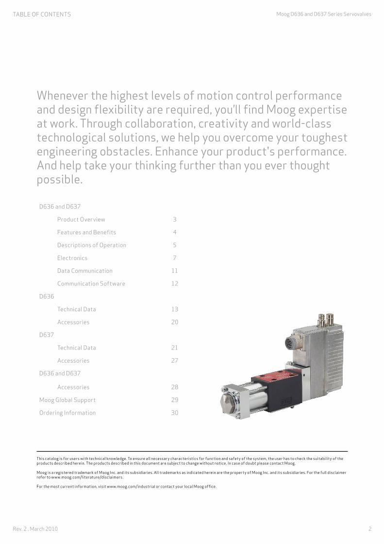
Whenever the highest levels of motion control performance and design flexibility are required, you’ll find Moog expertise at work. Through collaboration, creativity and world-class technological solutions, we help you overcome your toughest engineering obstacles. Enhance your product's performance. And help take your thinking further than you ever thought possible.
This catalog is for users with technical knowledge. To ensure all necessary characteristics for function and safety of the system, the user has to check the suitability of the products described herein. The products described in this document are subject to change without notice. In case of doubt please contact Moog.
Moog is a registered trademark of Moog Inc. and its subsidiaries. All trademarks as indicated herein are the property of Moog Inc. and its subsidiaries. For the full disclaimer refer to www.moog.com/literature/disclaimers.
For the most current information, visit www.moog.com/industrial or contact your local Moog office.
D636 and D637
Product Overview 3
Features and Benefits 4
Descriptions of Operation 5
Electronics 7
Data Communication 11
Communication Software 12
D636
Technical Data 13
Accessories 20
D637
Technical Data 21
Accessories 27
D636 and D637
Accessories 28
Moog Global Support 29
Ordering Information 30
TAblE OF COnTEnTS
3
Moog D636 and D637 Series Servovalves,
Rev. 2 , March 2010
Excellence in motion control technology
For over 55 years Moog has ranked amongst the leading providers of motion control technology providing high performance products. Moog offers worldclass products using state of the art control techniques that contribute to the performance improvement of machines.
Moog Servovalves and Servo-Proportional Valves
Moog has been producing Servovalves and Servo-Proportional Valves with integrated electronics for over 30 years. Our valves are used in all kinds of machine applications.
Direct drive servovalves
The D636 and D637 Series Valves, sizes 03 and 05 are Direct Drive Servovalves with flow control.
The valves are throttle control valves for 4-(2-, 3-, 2x2-) way applications and are suitable for electrohydraulic control of position, speed, pressure and force even under high dynamic requirements.
Design and application
A permanent magnet linear force motor is used to drive the spool. In contrast to proportional solenoid drives, the linear force motor drives the spool in both working directions from the spring-centered middle position. The strong actuating force of the spool, provides Moog Servovalves with excellent static and dynamic characteristics.
PRODuCT OVERVIEw

4
Moog D636 and D637 Series Servovalves
Rev. 2 , March 2010
Digital electronics
The digital driver and control electronics are integrated in the valve. The valve electronics contain a microprocessor system which executes all the important functions via the valve software it contains. The digital electronics enables the valve to be controlled across the full range of operation, with significantly reduced influence from temperature and drift.
Fieldbus interface
A built-in fieldbus interface (e.g. CANopen®, Profibus-DP® or EtherCAT®) enables operating parameters to be set, activates the valve and monitors its performance. To reduce wiring, the fieldbus interface is provided with two connectors. Thus, valves may be integrated into the bus without any external T-joints. In addition, up to two analog input commands and up to two analog actual value outputs are available.
Optionally, the valves are available without a fieldbus interface. In this case, the valve is controlled using analog inputs. Valve parameters are set using the integrated M8 service connector.
Axis control
In addition, axis control functionality such as position control, velocity control and force control can be added to the valves. The control mode can be switched over from one to the other by defined events.
Our application engineers can assist you with any additional information you may require.
Benefits of Direct Drive Servovalves with integrated digital electronics
• Fieldbus data transfer: Electrically isolated fieldbus interface
• Diagnostic capabilities: Integrated monitoring of important ambient and internal data. Valve parameters can be changed on site or remotely
• Flexibility: Since parameters may be downloaded using the fieldbus or a high level PLC program, valve parameters may be tuned during a machine cycle while the machine is operating
• Direct drive with permanent magnet linear force motor that provides high actuating force, works in 2 directions
• Pilot oil not required
• Pressure-independent dynamic response
• Low hysteresis and high response characteristics
• Low power demand at and in the proximity of hydraulic zero. Hydraulic zero is the spool position at which the pressures of a symmetrical spool are equal in both blocked control ports
• If the electrical supply fails, a cable breaks or emergency stop is activated, the spool returns to the predefined spring-centered position without passing a fully open control port position (fail-safe) increasing safety
D636 Series single-stage drive servovalve
Fieldbus connector X4
Fieldbus connector X3
Status LEDs
Digital electronics
Position transducer (LVDT)
Valve connector X1
Service connector X10
Spool
Bushing
Linear force motor
Ports
FEATuRES AnD bEnEFITS
5
Moog D636 and D637 Series Servovalves,
Rev. 2 , March 2010
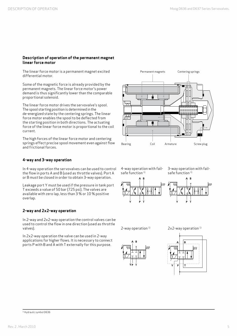
Description of operation of the permanent magnet linear force motor
The linear force motor is a permanent magnet excited differential motor. Some of the magnetic force is already provided by the permanent magnets. The linear force motor's power demand is thus significantly lower than the comparable proportional solenoid.
The linear force motor drives the servovalve's spool. The spool starting position is determined in the de-energized state by the centering springs. The linear force motor enables the spool to be deflected from the starting position in both directions. The actuating force of the linear force motor is proportional to the coil current.
The high forces of the linear force motor and centering springs effect precise spool movement even against flow and frictional forces.
4‑way and 3‑way operation
In 4-way operation the servovalves can be used to control the flow in ports A and B (used as throttle valves). Port A or b must be closed in order to obtain 3-way operation.
leakage port Y must be used if the pressure in tank port T exceeds a value of 50 bar (725 psi). The valves are available with zero lap, less than 3 % or 10 % positive overlap.
2‑way and 2x2‑way operation
In 2-way and 2x2-way operation the control valves can be used to control the flow in one direction (used as throttle valves).
In 2x2-way operation the valve can be used in 2-way applications for higher flows. It is necessary to connect ports P with b and A with T externally for this purpose.
Permanent magnets Centering springs
Bearing Coil Armature Screw plug
4-way operation with fail-safe function 1)
3-way operation with fail-safe function 1)
2-way operation 1) 2x2-way operation 1)
DESCRIPTIOn OF OPERATIOn
1) Hydraulic symbol D636

6
Moog D636 and D637 Series Servovalves
Rev. 2 , March 2010
Servovalve operational mode
The D636 and D637 Series Valves are valves with flow control. In this operating mode the position of the spool is controlled. The command signal corresponds to a particular spool position.
The command signal (spool position command) is transmitted to the valve electronics. The actual spool position is measured with a position transducer (lVDT) and transmitted to the valve electronics. The electronics compares the actual spool position and command signal and generates a signal to drive the linear force motor, which moves the spool into the corresponding position.
The position command can be modified by parameters in the valve software (e.g. linearization, ramping, dead band, sectionally defined amplification, etc.).
Flow calculation
The actual valve flow is dependent on the spool and the pressure drop Δp across the spool lands.
At 100 % command signal the valve flow at rated pressure drop Δpn = 35 bar (500 psi) per metering land is the rated flow Qn. For other than rated pressure drop, the valve flow changes at a constant signal according to the following formula.
The actual flow Q must not exceed a mean flow velocity of 30 m/s (96.54 ft/s) at ports P, A, b and T.
Flow DiAgrAM
Q [l/min (gpm)] = actual flow Qn [l/min (gpm)] = rated flowΔp [bar (psi)] = actual valve pressure drop Δpn [bar (psi)] = rated valve pressure drop
Q = QN. ∆p
∆pN
Q [l
/min
(gpm
)] 200 (52.8)
p [bar (psi)]
350(5000)
150 (39.6)
100 (26.4)
1 (0.26)
2 (0.53)
3 (0.79)
4 (1.1)
6 (1.6)
8 (2.1)
10 (2.6)
15 (4.0)
20 (5.3)
30 (7.9)
40 (10.6)
60 (15.9)
80 (21.1)
200(2900)
150(2175)
100(1450)
70(1000)
50(725)
30(435)
20(290)
10(145)
100 l/min (26.4 gpm) - D637
60 l/min (15.9 gpm) - D637
40 l/min (10.6 gpm) - D636
20 l/min (5.3 gpm) - D636
10 l/min (2.6 gpm) - D636
5 l/min (1.3 gpm) - D636
DESCRIPTIOn OF OPERATIOn
7
Moog D636 and D637 Series Servovalves,
Rev. 2 , March 2010
ElECTROnICS
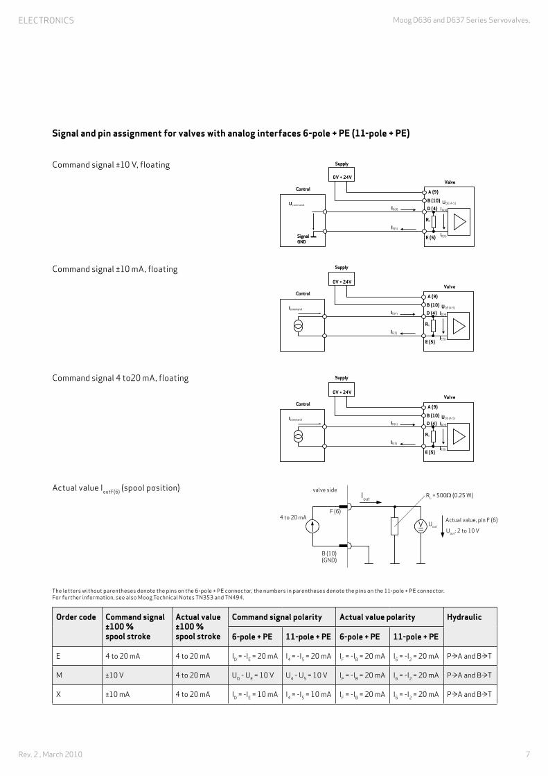
order code Command signal±100 %spool stroke
Actual value±100 %spool stroke
Command signal polarity Actual value polarity Hydraulic
6-pole + PE 11-pole + PE 6-pole + PE 11-pole + PE
E 4 to 20 mA 4 to 20 mA ID = -IE = 20 mA I4 = -I5 = 20 mA IF = -Ib = 20 mA I6 = -I2 = 20 mA P≥A and B≥T
M ±10 V 4 to 20 mA uD - uE = 10 V u4 - u5 = 10 V IF = -Ib = 20 mA I6 = -I2 = 20 mA P≥A and B≥T
X ±10 mA 4 to 20 mA ID = -IE = 10 mA I4 = -I5 = 10 mA IF = -Ib = 20 mA I6 = -I2 = 20 mA P≥A and B≥T
B (10)
D (4) ID(4)
IE(5)
A (9)
Re
UDE (4-5)
Valve
Supply
Control
SignalGND
0V + 24V
Ucommand
E (5)
ID(4)
IE(5)
B (10)
D (4) ID(4)
IE(5)
A (9)
Re
UDE (4-5)
Valve
Supply
Control
0V + 24V
Icommand
E (5)
ID(4)
IE(5)
B (10)
D (4) ID(4)
IE(5)
A (9)
Re
UDE (4-5)
Valve
Supply
Control
0V + 24V
Icommand
E (5)
ID(4)
IE(5)
valve sideIout
Rl = 500W (0.25 w)
Actual value, pin F (6)F (6)
b (10)(GnD)
4 to 20 mA
uout: 2 to 10 VuoutV
Command signal ±10 V, floating
Command signal ±10 mA, floating
Command signal 4 to20 mA, floating
Actual value IoutF(6) (spool position)
The letters without parentheses denote the pins on the 6-pole + PE connector, the numbers in parentheses denote the pins on the 11-pole + PE connector. For further information, see also Moog Technical notes Tn353 and Tn494.
Signal and pin assignment for valves with analog interfaces 6‑pole + PE (11‑pole + PE)

8
Moog D636 and D637 Series Servovalves
Rev. 2 , March 2010
Pin assignment for valves with 6‑pole + PE connector (X1)
Pin assignment as per En 175201-804, mating connector (type R or S, metal) with preleading earth pin ( ).
Pin Pin assignment Voltage, floating ±10 V
Current, floating ±10 mA, 4 to 20 mA 1)
A Supply voltage 24 V DC (18 to 32 V DC) referred to GnD (polarized against GnD)
B GnD Supply ground / signal ground
C Enable input > 8.5 to 32 V DC referred to GND: valve ready for operation (enabled)
< 6.5 V DC referred to GND: valve not ready for operation (disabled) The input resistance is 10 kW.
D Command signal, difference amplifier input 2)
uin = uD-E
Rin = 20 kW
Iin = ID = -IE
Rin = 200 WImax = ±25 mAE
F Actual value output Iout: 4 to 20 mA referred to GND (Iout is proportional to the spool position.12 mA corresponds to the valve center position.)
Protective earth (PE) Connected with valve body
1) Command signals Iin < 3 mA (e.g. due to an open circuit) indicate a fault in the 4 to 20 mA signal range. The valve response to this fault can be configured and activated by the customer.
2) The potential difference (referred to GnD) must be between -15 V and +32 V.
ElECTROnICS

9
Moog D636 and D637 Series Servovalves,
Rev. 2 , March 2010
Pin assignment for valves with 11‑pole + PE connector (X1)
Pin assignment as per En 175201-804, mating connector (metal) with preleading protective earth pin ( ).
Pin Pin assignment Voltage, floating ±10 V
Current, floating ±10 mA, 4 to 20 mA1)
1not assigned
2
3 Enable input > 8.5 to 32 V DC referred to GND: valve ready for operation (enabled)
< 6.5 V DC referred to GND: valve not ready for operation (disabled)The input resistance is 10 kW.
4Command input, difference amplifier input 2)
uin = u4-5
Rin = 20 kW
Iin = I4 = -I5
Rin = 200 WImax = ±25 mA5
6 Actual value output Iout = 4 to 20 mA referred to GnD. Rl = 500 W (Iout is proportional to the spool position. 12 mA corresponds to the valve center position.)
7 not assigned
8 Digital output, valve status ON: enable & supply OK. Valve is ready for operation.Nominal load voltage: 24 VDC, Load type: ohmic, inductive, lamp loadOutput current maximum 1.5 A (short-circuit-proof) 3)
9 Supply voltage 24 V DC (18 to 32 V DC) referred to GnD (polarized against GnD)
10 GnD Supply ground / signal ground
11 Digital output OFF: indicates fault 4)
Nominal load voltage: 24 VDC, Load type: ohmic, inductive, lamp loadOutput current maximum 1.5 A (short-circuit-proof) 3)
Protective earth (PE) Connected with valve body
1) Command signals Iin < 3 mA (e.g. due to an open circuit) indicate a fault in the 4 to 20 mA signal range. The valve response to this fault can be configured and activated by the customer.
2) The potential difference (referred to GnD) must be between -15 V and +32 V.
3) The sum total of the currents drawn at the outputs pin 8 & pin 11 (measured to GnD) must be added to the valve supply current. The valve fuse must be configured for the total current.
4) Output can be programmed at the factory, "OFF“ signal indicates fault (e.g. command signal/actual value deviation).
1
2
3
410
5
9�
11
8
7
6
ElECTROnICS

10
Moog D636 and D637 Series Servovalves
Rev. 2 , March 2010
Profibus‑DP® connectors (X3, X4)
• Coding b • Thread M12x1 • 5-pole
Pin Signal X3, X4 Description
1 Profi V+ Supply voltage 5 V of terminal resistors
2 Profi A Receive/transmit data –
3 Profi GND Ground
4 Profi B Receive/transmit data +
5 Shield Shield
3
3245
1
2 15
4
External thread, pin contacts
Internal thread, socket contacts
View on Profibus-DP connector X3
View on Profibus-DP connector X4
CANopen® connectors (X3, X4)
• Coding A • Thread M12x1 • 5-pole
Pin Signal X3, X4 Description
1 CAn_SHlD Shield
2 CAn_V+ not connected in the valve
3 CAn_GnD Ground
4 CAn_H Transceiver H
5 CAn_l Transceiver l
3
3245
1
2 15
4
External thread, pin contacts
Internal thread, socket contacts
View onCAN connector X3
View on CAN connector X4
EtherCAT® IN & OUT connectors (X3, X4)
• Coding D • Thread M12x1 • 4-pole
Pin Signal X4 IN Signal X3 OUT Description
1 TX + In TX + OuT Transmit
2 RX + In RX + OuT Receive
3 TX – In TX – OuT Transmit
4 RX – In RX – OuT Receive
32
1 4
32
1 4
Internal thread, socket contacts
Internal thread, socket contacts
View on EtherCAT connector X3
View on EtherCAT connector X4
ElECTROnICS

11
Moog D636 and D637 Series Servovalves,
Rev. 2 , March 2010
general information
Modern automation technology is characterized by an increasing decentralization of processing functions via serial data communication systems. The use of serial bus systems in place of conventional connection technologies guarantees greater system flexibility with regard to alterations and expansions. It additionally opens up considerable potential for saving project planning and installation costs in many areas of industrial automation. Further possibilities of parameterization, better diagnostic options and a reduction of the variety of variants are advantages which have only been made possible by the use of fieldbuses.
VDMA profile
In one working group within the VDMA (German Machinery and Plant Manufacturers’ Association), a profile was created in collaboration with numerous well-known hydraulic system manufacturers. This profile describes communication between hydraulic components via a fieldbus. It defines uniform functions and parameters in a standardized exchange format.
CANopen®
In accordance with En 50325-4. The CAn bus was originally developed for use in automobiles, but has also been used for years in various fields of machine construction. The CAn bus is designed above all for transmission reliability and speed. The CAN bus has the following features:
• Multi-master system: Each node can transmit and receive
• Topology: line structure with short stub lines
• Network extension and band widths: 25 m (80.4 ft) at 1 Mbit/s to 5000 m (16090 ft) at 25 kbit/s
• Addressing type: Message-orientated via identifiers. Priority assignment of the message via identifier
• Security: Hamming distance = 6, i.e. up to 6 individual errors per message are detected
• Bus physics: ISO 11989
• Maximum number of nodes: 127
Profibus‑DP®
In accordance with EN 61158. Profibus-DP® was developed for the process and manufacturing industries and is thereby supported by numerous control system manufacturers. The Profibus-DP® has the following features:
• Multi-master system: Several masters share access time and initiate communication. Slaves react only on request
• Topology: linear structure with short stub lines
• Network expansion and transmission rates: 100 m (321.8) at 12 Mbit/s to 1200 m (3861.6 ft) at 9.6 kbit/s per segment. use of repeaters possible
• Addressing type: Address-orientated. Priority/cycle time assignment of messages via master configuration
• Bus physics: RS-485 in accordance with EIA-485
• Maximum number of nodes: 126
EtherCAT®
In accordance with IEC/PAS 62407. EtherCAT® has been developed as an industry bus based on Ethernet to meet increasing demands regarding cycle time. The EtherCAT® bus is designed for high data transmission rates and fast cycle times. The EtherCAT® bus has the following features:
• Single-master system: Master initiates communication. Slaves react only on request
• Topology: line, star, tree and ring structure based on the daisy chain principle
• Network expansion and transmission rates: 100 m (321.8 ft) between two nodes, 100 Mbit/s
• Addressing type: Address-orientated, one datagram for all nodes
• Bus physics: Fast Ethernet 100 base Tx
• Maximum number of nodes: 65535
DATA COMMunICATIOn

12
Moog D636 and D637 Series Servovalves
Rev. 2 , March 2010
general information
The Windows®-based “Moog Valve Configuration Software” developed by Moog enables fast and convenient commissioning, diagnostics and configuration of the valve. Data may be uploaded from the PC to the valve and; current settings may be downloaded from the valve to the PC and displayed. The valve can be controlled by means of graphic control elements.Status information, command signals, actual values and characteristic curves are represented in graphical form. System parameters can be recorded and visualized by means of an integrated oscilloscope / data logger.
Configuration software
System requirements:The configuration software can be installed on a PC with the following minimal requirements:
• IBM PC-compatible with 133 MHz
• Windows® 95/98/ME, Windows® NT/2000/XP/Vista
• 64 MB RAM
• 40 MB free hard disk space
• Monitor 640x480 pixel resolution
• Keyboard, mouse
recommended requirements:
• IBM PC-compatible with 300 MHz
• Windows® NT/2000/XP/Vista
The following equipment is also required to be able to use the software (see section "D636 and D637 Accessories"):
• Free USB port
• USB starting-up module
• Configuration/commissioning cable
• Valve connection cable (6-pole + PE or 11-pole + PE)
• Adapter for M8 service connector (not necessary for valves with CANopen® interface)
• Power pack 24 V DC / 2 A
Note
Configuration/starting-up with the “Moog Valve Configuration Software” can be performed on valves with a CANopen® interface via the fieldbus connectors, otherwise (valves with Profibus-DP® or EtherCAT® interface or purely analog activation) via the integrated M8 service connector. It is not permitted to operate the "Moog Valve Configuration Software“ on a fieldbus while the bus is communicating.
The software is available from Moog upon request.
COMMunICATIOn SOFTwARE

13
Moog D636 and D637 Series Servovalves,
Rev. 2 , March 2010
Technical data Description
Design Single-stage spool valve with bushing
Actuation Directly with permanent magnet linear force motor
Valve configuration 2-way, 3-way, 4-way and 2x2-way operation
Mounting pattern ISO 4401-03-03-0-05 (with or without leakage port Y)
Diameter of ports 7.9 mm (0.31 in)
installation position As desired
Mass 2.5 kg (5.5 lb)
Storage temperature range -40 °C to +80 °C (-40 °F to +176 °F)
Ambient temperature range -20 °C to +60 °C (-4 °F to +140 °F)
Vibration resistance 30 g, 3 axes, 10 Hz to 2 kHz (as per En 60068-2-6)
Shock resistance 50 g, 6 directions, half-sine 3 ms (as per En 60068-2-27)
D636 | TECHnICAl DATA
D636 Series Servovalve with rated flow up to 40 l/min (10.6 gpm)

14
Moog D636 and D637 Series Servovalves
Rev. 2 , March 2010
Hydraulic data (measured at 140 bar (2,000 psi), fluid viscosity 32 mm2/s (cSt) and fluid temperature 40 °C (104 °F))
Technical data Description
Maximum operating pressure range, port P, A, B 350 bar (5,000 psi)
Maximum operating pressure range, port T without Y 50 bar (725 psi)
Maximum operating pressure range, port T with Y 350 bar (5,000 psi)
Maximum operating pressure range, port Y Depressurized to tank
Maximum flow 75 l/min (19.8 gpm)
Rated flow (model‑dependent) at Δp rated 35 bar (500 psi)/land
5 / 10 / 20 / 40 l/min (1.3 / 2.6 / 5.3 / 10.6 gpm)
Leakage flow at zero lap (model‑dependent)
0.15 / 0.3 / 0.6 / 1.2 l/min (0.04 / 0.08 / 0.16 / 0.32 gpm)
Hydraulic fluid Hydraulic fluid as per DIN 51524 Parts 1 to 3 and ISO 11158Other fluids upon request
Seal material HNBR, FKM, others upon request
Temperature range of hydraulic fluid -20 °C to +80 °C (-4 °F to +176 °F)
Viscosity range, recommended 15 mm2/s (cSt) to 100 mm2/s (cSt)
Viscosity range, maximum permissible 5 mm2/s (cSt) to 400 mm2/s (cSt)
recommended cleanliness class for functional safety as per iSo 4406 1)
< 18 / 15 / 12
Recommended cleanliness class for endurance (wear) as per iSo 4406 1)
< 17 / 14 / 11
Typical static and dynamic data
Technical data Description
Step response time for 0 to 100 % stroke (typical) 8 ms
Hysteresis < 0.05 % (typical) 0.10 % (maximum)
Null shift at ΔT = 55 K < 1.5 %
Manufacturing tolerance with respect to Q_rated < 3 %
1) The cleanliness of the hydraulic fluid has a great effect on functional safety (reliable spool positioning, high resolution) and wear of the spool lands (pressure gain, leakage losses).
D636 | TECHnICAl DATA

15
Moog D636 and D637 Series Servovalves,
Rev. 2 , March 2010
Electrical data Description
Duty factor 100 %
Degree of protection as per EN 60529 IP 65 with mounted mating connectors or with mounted dust protection caps with sealing function
Supply voltage 18 V DC to 32 V DC (see Electronics section)
Maximum current consumption 1.7 A
Fuse protection, external, per valve 2 A (slow-blowing)
Power consumption of motor in neutral position 9.6 w (0.4 A at 24 V DC)
Maximum power consumption 28.8 w (1.2 A at 24 V DC)
EM compatibility Emitted interference as per EN 61000-6-4:2005, (CAnopen® and Profibus-DP®);Emitted interference as per EN 61000-6-3:2005, (EtherCAT®);Immunity to interference as per EN 61000-6-2:2005, (evaluation criterion A);
Connector type See Electronics section
Triggering electronics Integrated in the valve, see Electronics section
D636 | TECHnICAl DATA

16
Moog D636 and D637 Series Servovalves
Rev. 2 , March 2010
Characteristic curves (typical) 1)
STEP rESPoNSE
-80
-60
-40-20
0
20
10080
60
40
Command signal [%]
[%]
-100 1006020-20-60-4Command signal [%]
-3 -2 -1 0 1 2 3 4
[%]
p AB
p P
Δ
Frequency [Hz]
Phas
e la
g [d
egre
es]
Am
plit
ude
rati
o [d
B]
10 1001 10000
- 30
- 60
- 90
- 120
- 150
+/– 25%
+/– 90%
+/– 10%
+/– 05%
-12
-9
-6
-3
0
3
Time [ms]
Stro
ke [%
]
0
25
50
75
100
0 5 10 15 20
FREQUENCY RESPONSE
-80
-60
-40-20
0
20
10080
60
40
Command signal [%]
[%]
-100 1006020-20-60-4Command signal [%]
-3 -2 -1 0 1 2 3 4
[%]
p AB
p P
Δ
Frequency [Hz]
Phas
e la
g [d
egre
es]
Am
plit
ude
rati
o [d
B]
10 1001 10000
- 30
- 60
- 90
- 120
- 150
+/– 25%
+/– 90%
+/– 10%
+/– 05%
-12
-9
-6
-3
0
3
Time [ms]
Stro
ke [%
]
0
25
50
75
100
0 5 10 15 20
PrESSurE SigNAl CurVE(valve with zero lap)
-80
-60
-40-20
0
20
10080
60
40
Command signal [%]
[%]
-100 1006020-20-60-4Command signal [%]
-3 -2 -1 0 1 2 3 4
[%]
p AB
p P
Δ
Frequency [Hz]
Phas
e la
g [d
egre
es]
Am
plit
ude
rati
o [d
B]
10 1001 10000
- 30
- 60
- 90
- 120
- 150
+/– 25%
+/– 90%
+/– 10%
+/– 05%
-12
-9
-6
-3
0
3
Time [ms]
Stro
ke [%
]
0
25
50
75
100
0 5 10 15 20
VAlVE Flow SigNAl CurVE(valve with zero lap)
-80
-60
-40-20
0
20
10080
60
40
Command signal [%]
[%]
-100 1006020-20-60-4Command signal [%]
-3 -2 -1 0 1 2 3 4
[%]
p AB
p P
Δ
Frequency [Hz]
Phas
e la
g [d
egre
es]
Am
plit
ude
rati
o [d
B]
10 1001 10000
- 30
- 60
- 90
- 120
- 150
+/– 25%
+/– 90%
+/– 10%
+/– 05%
-12
-9
-6
-3
0
3
Time [ms]
Stro
ke [%
]
0
25
50
75
100
0 5 10 15 20
1) At operating pressure pp = 140 bar (2,000 psi), fluid viscosity ν = 32 mm2/s (cSt) and a fluid temperature of 40° C (104 °F)
D636 | TECHnICAl DATA

17
Moog D636 and D637 Series Servovalves,
Rev. 2 , March 2010
iNSTAllATioN DrAwiNgS For VAlVES wiTH CANoPEN FiElDBuS CoNNECTor
6 5
(2.6
) R
emov
al s
pace
, fi
eldb
us
mat
ing
conn
ecto
r 6
(0.24)
Fieldbus connector X4
Fieldbus connector X3
85 (3.4)
106 (4.2)
147
(5.8
)
125
(4.9
)
49 (1.9)
107
(4.2
)3
(0.1
2)
134 (5.9)
17(0.67)
Ø12,4(0,49)
Ø11(0,43)
Ø 9,5(0.37)
Ø 5,4 (0.21)
Removal space,
mating connector
108 (4.3)*
Valve connector X1
76,5 (3.0)
8 (0.31)
1 (0.04)*/
47
(1.9
)
77 (3.0) /
Service connector X10
Valve connector X1
41 ( 1.6)
Removal space, service
mating connector
* Dimensions for 11+PE connector
259 (10.2)
80
(3.2
)
5 (0.20)
259 (10.2)
151 (5.9)
17 (0.67)
Ø 12,4 (0.49)
Ø 11 (0.43)
47
(1.9
)
Ø 9,5 (0.37)Ø 5,4 (0.21)
Removal space,
mating connector
77 (3.0)
65
(2.6
)R
emov
al s
pace
, fi
eldb
us
mat
ing
conn
ecto
r
117 (4.6) /
124 (4.9)*
147
(5.8
)
125
(4.9
)
49 (1.9)
107
(4.2
)
6 (0.24)
* Dimensions for 11+PE connector
Valve connector X1Fieldbus
connector X4
Fieldbus connector X3
40 (1.6)
19 (0.75)
3 (0
.12)
108 (4.3)*
/
iNSTAllATioN DrAwiNgS For VAlVES wiTH ProFiBuS-DP or ETHErCAT FiElDBuS CoNNECTor
50 (2.0)
Removal space, service
mating connector
Valve connector X1
Service connector X10
connector X4
Fieldbus connector X3Fieldbus
5 (0.20)
80
(3.1
)
D636 | TECHnICAl DATA

18
Moog D636 and D637 Series Servovalves
Rev. 2 , March 2010
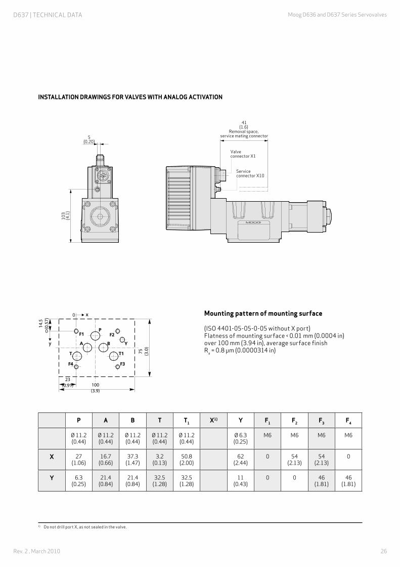
iNSTAllATioN DrAwiNgS For VAlVES wiTH ANAlog ACTiVATioN
6 5
(2.6
) R
emov
al s
pace
, fi
eldb
us
mat
ing
conn
ecto
r
6 (0.24)
Fieldbus connector X4
Fieldbus connector X3
85 (3.4)
106 (4.2)
147
(5.8
)
125
(4.9
)
49 (1.9)
107
(4.2
)3
(0.1
2)
134 (5.9)
17(0.67)
Ø12,4(0,49)
Ø11(0,43)
Ø 9,5(0.37)
Ø 5,4 (0.21)
Removal space,
mating connector
108 (4.3)*
Valve connector X1
76,5 (3.0)
8 (0.31)
1 (0.04)*/
47
(1.9
)
77 (3.0) /
Service connector X10
Valve connector X1
41 ( 1.6)
Removal space, service
mating connector
* Dimensions for 11+PE connector
259 (10.2)
80
(3.2
)
5 (0.20)
259 (10.2)
151 (5.9)
17 (0.67)
Ø 12,4 (0.49)
Ø 11 (0.43)
47
(1.9
)
Ø 9,5 (0.37)Ø 5,4 (0.21)
Removal space,
mating connector
77 (3.0)
65
(2.6
)R
emov
al s
pace
, fi
eldb
us
mat
ing
conn
ecto
r
117 (4.6) /
124 (4.9)*
147
(5.8
)
125
(4.9
)
49 (1.9)
107
(4.2
)
6 (0.24)
* Dimensions for 11+PE connector
Valve connector X1Fieldbus
connector X4
Fieldbus connector X3
40 (1.6)
19 (0.75)
3 (0
.12)
108 (4.3)*
/
D636 | TECHnICAl DATA

19
Moog D636 and D637 Series Servovalves,
Rev. 2 , March 2010
Mounting pattern of mounting surface
(ISO 4401-03-03-0-05) Flatness of mounting surface < 0.01 mm (0.0004 in) over 100 mm (3.94 in), average surface finish Ra = 0.8 µm (0.0000314 in)
P A B T X1) Y F1 F2 F3 F4 g2)
Ø 7.5 (0.30)
Ø 7.5 (0.30)
Ø 7.5 (0.30)
Ø 7.5 (0.30)
Ø 3.3 (0.13) M5 M5 M5 M5 Ø 4
(0.16)
X 21.5 (0.85)
12.7 (0.50)
30.2 (1.19)
21.5 (0.85)
40.5 (1.59) 0 40.5
(1.59)40.5
(1.59) 0 33 (1.30)
Y 25.9 (1.02)
15.5 (0.61)
15.5 (0.61)
5.1 (0.20)
9 (0.35) 0 -0.75
(-0.03)31.75 (1.25)
31 (1.22)
31.75 (1.25)
9.5
(0.3
7)
0
017(0.67)
77 (3.0)
52 (2
.1)
F1F2
F4 F3
x
y
1) Do not drill port X, as not sealed in the valve.2) Minimum 4 mm (0.157 in) depth
D636 | TECHnICAl DATA

20
Moog D636 and D637 Series Servovalves
Rev. 2 , March 2010
D636 - Spare parts
Part designation Description Part number
Shipping plate b46035-001
o-rings for ports P, T, A, B (4 rings per valve required)
ID 9.25 x Ø 1.8: HNBR 90 Shore (ID 0.36 x Ø 0.07)
b97009-013
o-ring for ports P, T, A, B (4 rings per valve required)
ID 9.25 x Ø 1.8: FKM 90 Shore (ID 0.36 x Ø 0.07)
-42082-013
O‑ring for port Y ID 7.65 Ø 1.8: HNBR 90 Shore (ID 0.3 x Ø 0.07)
b97009-012
O‑ring for port Y ID 7.65 Ø 1.8: FKM 90 Shore (ID 0.3 x Ø 0.07)
-42082-012
D636 - Accessories
Part designation Description Part number
Service sealing kit with O‑rings for ports P, T, A, B, Y
HnbR 90 Shore b97215-H630F63
Service sealing kit with O‑rings for ports P, T, A, B, Y
FKM 90 Shore b97215-V630F63
Installation screws of servovalve (4 screws per valve required)
M5x55, ISO 4762-10.9tightening torque: 6.8 Nm (60 in-lbs)
A03665-050-055
Flushing plate for P, A, B, T, X, Y b46634-002
D636 - Documents
Designation Description Part number
Manual D636 Series Servovalves Operating instructions CA45707-001 1)
D636 | SPARE PARTS AnD ACCESSORIES
1) Download the document at www.moog.com/industrial/literature

21
Moog D636 and D637 Series Servovalves,
Rev. 2 , March 2010
D637 | TECHnICAl DATA
Technical data Description
Design Single-stage spool valve with bushing
Actuation Directly with permanent magnet linear force motor
Valve configuration 2-way, 3-way, 4-way and 2x2-way operation
Mounting pattern ISO 4401-05-05-0-05 (with or without leakage port Y)
Diameter of ports 11.5 mm (0.45 in)
installation position As desired
Mass 7.9 kg (17.4 lb)
Storage temperature range -40 °C to +80 °C (-40 °F to +176 °F)
Ambient temperature range -20 °C to +60 °C (-4 °F to +140 °F)
Vibration resistance 30 g, 3 axes, 10 Hz to 2 kHz (as per En 60068-2-6)
Shock resistance 50 g, 6 directions, half-sine 3 ms (as per En 60068-2-27)
D637 Series Servovalve with rated flow up to 100 l/min (26.4 gpm)

22
Moog D636 and D637 Series Servovalves
Rev. 2 , March 2010
Hydraulic data (measured at 140 bar (2,000 psi), fluid viscosity 32 mm2/s (cSt) and fluid temperature 40 °C (104 °F))
Technical data Description
Maximum operating pressure range, port P, A, B 350 bar (5,000 psi)
Maximum operating pressure range, port T, T1 without Y 50 bar (725 psi)
Maximum operating pressure range, port T, T1 with Y 210 bar (3,000 psi)
Maximum operating pressure range, port Y Depressurized to tank
Maximum flow 180 l/min (47.6 gpm)
Rated flow (model‑dependent) at Δp rated 35 bar (500 psi)/land
60 / 100 l/min (15.9 / 26.4 gpm)
Leakage flow at zero lap (model‑dependent)
1.2 / 2 l/min (0.32 / 0.53 gpm)
Hydraulic fluid Hydraulic fluid as per DIN 51524 Parts 1 to 3 and ISO 11158Other fluids upon request
Seal material NBR, FKM, others upon request
Temperature range of hydraulic fluid -20 °C to +80 °C (-4 °F to +176 °F)
Viscosity range, recommended 15 mm2/s(cSt) to 100 mm2/s (cSt)
Viscosity range, maximum permissible 5 mm2/s (cSt) to 400 mm2/s (cSt)
recommended cleanliness class for functional safety as per iSo 4406 1)
< 18 / 15 / 12
Recommended cleanliness class for endurance (wear) as per iSo 4406 1)
< 17 / 14 / 11
Typical static and dynamic data
Technical data Description
Step response time for 0 to 100 % stroke (typical) 14 ms
Hysteresis < 0.05 % (typical) 0.10 % (maximum)
Null shift at ΔT = 55 K < 1.5 %
Manufacturing tolerance with respect to Q_rated < 3 %
1) The cleanliness of the hydraulic fluid has a great effect on functional safety (reliable spool positioning, high resolution) and wear of the spool lands (pressure gain, leakage losses).
D637 | TECHnICAl DATA

23
Moog D636 and D637 Series Servovalves,
Rev. 2 , March 2010
D637 | TECHnICAl DATA
Electrical data Description
Duty factor 100 %
Degree of protection as per EN 60529 IP 65 with mounted mating connectors or with mounted dust protection caps with sealing function
Supply voltage 18 V DC to 32 V DC (see Electronics section)
Maximum current consumption 3.0 A
Fuse protection, external, per valve 3.15 A (slow-blowing)
Power consumption of motor in neutral position 9.6 w (0.4 A at 24 V DC)
Maximum power consumption 55.2 w (2.3 A at 24 V DC)
EM compatibility Emitted interference as per EN 61000-6-4:2005, (CAnopen® and Profibus-DP®);Emitted interference as per EN 61000-6-3:2005, (EtherCAT®);Immunity to interference as per EN 61000-6-2:2005, (evaluation criterion A);
Connector type See Electronics section
Triggering electronics Integrated in the valve, see Electronics section

24
Moog D636 and D637 Series Servovalves
Rev. 2 , March 2010
Characteristic curves (typical) 1)
STEP RESPONSE 60 L/MIN (15.9 GPM) VERSION-4
-100
-80
-60
-40-20
0
20
10080
60
40
Command signal [%]
[%]
-3 -2 -1 0 1 2 3 4
p AB
p P
Δ
100
80
60
40
20
0
– 20
– 40
– 60
– 80
– 100 – 60 – 20 20 60 100
Command signal [%]
[%]
0 5 10 15 20 25 30
Time [ms]
0
25
50
75
100
Stro
ke [%
]
0 5 10 15 20 25 30
Time [ms]
0
25
50
75
100
Stro
ke [%
]
1 10 100 1000
Frequency [Hz]
-12
-150
-9
-120
-6
-90-3
-60
0
-30
3
0
Am
plit
ude
rati
o [d
B]
Phas
e la
g [d
egre
es]
+/– 05%
+/– 25%
+/– 90%
+/– 10%
1 10 100 1000Frequency [Hz]
-12
-150
-9
-120
-6
-90-3
-60
0
-30
3
0
Am
plit
ude
rati
o [d
B]
Phas
e la
g [d
egre
es]
+/– 05%
+/– 25%
+/– 90%
+/– 10%
FREQUENCY RESPONSE 60 L/MIN (15.9 GPM) VERSION
-4-100
-80
-60
-40-20
0
20
10080
60
40
Command signal [%]
[%]
-3 -2 -1 0 1 2 3 4
p AB
p P
Δ
100
80
60
40
20
0
– 20
– 40
– 60
– 80
– 100 – 60 – 20 20 60 100
Command signal [%]
[%]
0 5 10 15 20 25 30
Time [ms]
0
25
50
75
100
Stro
ke [%
]
0 5 10 15 20 25 30
Time [ms]
0
25
50
75
100
Stro
ke [%
]
1 10 100 1000
Frequency [Hz]
-12
-150
-9
-120
-6
-90-3
-60
0
-30
3
0
Am
plit
ude
rati
o [d
B]
Phas
e la
g [d
egre
es]
+/– 05%
+/– 25%
+/– 90%
+/– 10%
1 10 100 1000Frequency [Hz]
-12
-150
-9
-120
-6
-90-3
-60
0
-30
3
0
Am
plit
ude
rati
o [d
B]
Phas
e la
g [d
egre
es]
+/– 05%
+/– 25%
+/– 90%
+/– 10%
PrESSurE CHArACTEriSTiC CurVE (valve with zero lap)
-4-100
-80
-60
-40-20
0
20
10080
60
40
Command signal [%]
[%]
-3 -2 -1 0 1 2 3 4
p AB
p P
Δ
100
80
60
40
20
0
– 20
– 40
– 60
– 80
– 100 – 60 – 20 20 60 100
Command signal [%]
[%]
0 5 10 15 20 25 30
Time [ms]
0
25
50
75
100
Stro
ke [%
]
0 5 10 15 20 25 30
Time [ms]
0
25
50
75
100
Stro
ke [%
]
1 10 100 1000
Frequency [Hz]
-12
-150
-9
-120
-6
-90-3
-60
0
-30
3
0
Am
plit
ude
rati
o [d
B]
Phas
e la
g [d
egre
es]
+/– 05%
+/– 25%
+/– 90%
+/– 10%
1 10 100 1000Frequency [Hz]
-12
-150
-9
-120
-6
-90-3
-60
0
-30
3
0
Am
plit
ude
rati
o [d
B]
Phas
e la
g [d
egre
es]
+/– 05%
+/– 25%
+/– 90%
+/– 10%
STEP RESPONSE 100 L/MIN (26.4 GPM) VERSION-4
-100
-80
-60
-40-20
0
20
10080
60
40
Command signal [%]
[%]
-3 -2 -1 0 1 2 3 4
p AB
p P
Δ100
80
60
40
20
0
– 20
– 40
– 60
– 80
– 100 – 60 – 20 20 60 100
Command signal [%]
[%]
0 5 10 15 20 25 30
Time [ms]
0
25
50
75
100
Stro
ke [%
]
0 5 10 15 20 25 30
Time [ms]
0
25
50
75
100
Stro
ke [%
]
1 10 100 1000
Frequency [Hz]
-12
-150
-9
-120
-6
-90-3
-60
0
-30
3
0
Am
plit
ude
rati
o [d
B]
Phas
e la
g [d
egre
es]
+/– 05%
+/– 25%
+/– 90%
+/– 10%
1 10 100 1000Frequency [Hz]
-12
-150
-9
-120
-6
-90-3
-60
0
-30
3
0
Am
plit
ude
rati
o [d
B]
Phas
e la
g [d
egre
es]
+/– 05%
+/– 25%
+/– 90%
+/– 10%
FREQUENCY RESPONSE 100 L/MIN (26.4 GPM) VERSION
-4-100
-80
-60
-40-20
0
20
10080
60
40
Command signal [%]
[%]
-3 -2 -1 0 1 2 3 4
p AB
p P
Δ
100
80
60
40
20
0
– 20
– 40
– 60
– 80
– 100 – 60 – 20 20 60 100
Command signal [%]
[%]
0 5 10 15 20 25 30
Time [ms]
0
25
50
75
100
Stro
ke [%
]
0 5 10 15 20 25 30
Time [ms]
0
25
50
75
100
Stro
ke [%
]
1 10 100 1000
Frequency [Hz]
-12
-150
-9
-120
-6
-90-3
-60
0
-30
3
0
Am
plit
ude
rati
o [d
B]
Phas
e la
g [d
egre
es]
+/– 05%
+/– 25%
+/– 90%
+/– 10%
1 10 100 1000Frequency [Hz]
-12
-150
-9
-120
-6
-90-3
-60
0
-30
3
0
Am
plit
ude
rati
o [d
B]
Phas
e la
g [d
egre
es]
+/– 05%
+/– 25%
+/– 90%
+/– 10%
Flow SigNAl CHArACTEriSTiC CurVE(valve with zero lap)
-4-100
-80
-60
-40-20
0
20
10080
60
40
Command signal [%]
[%]
-3 -2 -1 0 1 2 3 4
p AB
p P
Δ
100
80
60
40
20
0
– 20
– 40
– 60
– 80
– 100 – 60 – 20 20 60 100
Command signal [%]
[%]
0 5 10 15 20 25 30
Time [ms]
0
25
50
75
100
Stro
ke [%
]
0 5 10 15 20 25 30
Time [ms]
0
25
50
75
100
Stro
ke [%
]
1 10 100 1000
Frequency [Hz]
-12
-150
-9
-120
-6
-90-3
-60
0
-30
3
0
Am
plit
ude
rati
o [d
B]
Phas
e la
g [d
egre
es]
+/– 05%
+/– 25%
+/– 90%
+/– 10%
1 10 100 1000Frequency [Hz]
-12
-150
-9
-120
-6
-90-3
-60
0
-30
3
0
Am
plit
ude
rati
o [d
B]
Phas
e la
g [d
egre
es]
+/– 05%
+/– 25%
+/– 90%
+/– 10%
1) At operating pressure pp = 140 bar (2,000 psi), fluid viscosity ν = 32 mm2/s (cSt)and a fluid temperature of 40 °C (104 °F)
D637 | TECHnICAl DATA

25
Moog D636 and D637 Series Servovalves,
Rev. 2 , March 2010
iNSTAllATioN DrAwiNgS For VAlVES wiTH CANoPEN FiElDBuS CoNNECTor
41(1.6)
Removal space, service mating connector
Valve connector X1
Service connector X10
Service connector X10
41(1.6)
Removal space, service mating connector
Valve connector X1
Fieldbus connector X4
Fieldbus connector X3
Removal space,
mating connector
65 (2.6
) R
emov
al s
pace
, fi
eldb
us
mat
ing
conn
ecto
r
Valve connector X1Fieldbus
connector X4Fieldbus connector X3
* Dimensions for 11+PE connector
77(3.0)
108(4.3)/
/
95(3.7)
116(4.6)
18(0.71)
11*(0.43)
170
(6.7
)14
9(5
.9)
130
(5.1
)
85,3
(3.4
)14
7(5
.8)
50,3
(2.0
)
73(2.9)
48(1.9)
6(0.24)
47 (1.9
)
313(12.3)
178(7.0)
23(0.91)
Ø18,7(0.74)
(2x)
Ø15,7(0.62)
(5x) 100(3.9)
103
(4.1
)
5(0.20)
103
(4.1
)
5(0.20)
Ø 11 (0.43)Ø 6,5 (0.26)
iNSTAllATioN DrAwiNgS For VAlVES wiTH ProFiBuS-DP or ETHErCAT FiElDBuS CoNNECTor
41(1.6)
Removal space, service mating connector
Valve connector X1
Service connector X10
Service connector X10
41(1.6)
Removal space, service mating connector
Valve connector X1
Fieldbus connector X4
Fieldbus connector X3
Removal space,
mating connector
65 (2.6
) R
emov
al s
pace
, fi
eldb
us
mat
ing
conn
ecto
r
Valve connector X1Fieldbus
connector X4Fieldbus connector X3
* Dimensions for 11+PE connector
77(3.0)
108(4.3)/
/
95(3.7)
116(4.6)
18(0.71)
11*(0.43)
170
(6.7
)14
9(5
.9)
130
(5.1
)
85,3
(3.4
)14
7(5
.8)
50,3
(2.0
)
73(2.9)
48(1.9)
6(0.24)
47 (1.9
)
313(12.3)
178(7.0)
23(0.91)
Ø18,7(0.74)
(2x)
Ø15,7(0.62)
(5x) 100(3.9)
103
(4.1
)
5(0.20)
103
(4.1
)
5(0.20)
Ø 11 (0.43)Ø 6,5 (0.26)
D637 | TECHnICAl DATA
26
Moog D636 and D637 Series Servovalves
Rev. 2 , March 2010
iNSTAllATioN DrAwiNgS For VAlVES wiTH ANAlog ACTiVATioN
41(1.6)
Removal space, service mating connector
Valve connector X1
Service connector X10
Service connector X10
41(1.6)
Removal space, service mating connector
Valve connector X1
Fieldbus connector X4
Fieldbus connector X3
Removal space,
mating connector
65 (2.6
) R
emov
al s
pace
, fi
eldb
us
mat
ing
conn
ecto
r
Valve connector X1Fieldbus
connector X4Fieldbus connector X3
* Dimensions for 11+PE connector
77(3.0)
108(4.3)/
/
95(3.7)
116(4.6)
18(0.71)
11*(0.43)
170
(6.7
)14
9(5
.9)
130
(5.1
)
85,3
(3.4
)14
7(5
.8)
50,3
(2.0
)
73(2.9)
48(1.9)
6(0.24)
47 (1.9
)
313(12.3)
178(7.0)
23(0.91)
Ø18,7(0.74)
(2x)
Ø15,7(0.62)
(5x) 100(3.9)
103
(4.1
)
5(0.20)
103
(4.1
)
5(0.20)
Ø 11 (0.43)Ø 6,5 (0.26)
Mounting pattern of mounting surface
(ISO 4401-05-05-0-05 without X port) Flatness of mounting surface < 0.01 mm (0.0004 in) over 100 mm (3.94 in), average surface finish Ra = 0.8 µm (0.0000314 in)
P A B T T1 X1) Y F1 F2 F3 F4
Ø 11.2 (0.44)
Ø 11.2 (0.44)
Ø 11.2 (0.44)
Ø 11.2 (0.44)
Ø 11.2 (0.44)
Ø 6.3 (0.25)
M6 M6 M6 M6
X 27 (1.06)
16.7 (0.66)
37.3 (1.47)
3.2 (0.13)
50.8 (2.00)
62 (2.44)
0 54 (2.13)
54 (2.13)
0
Y 6.3 (0.25)
21.4 (0.84)
21.4 (0.84)
32.5 (1.28)
32.5 (1.28)
11 (0.43)
0 0 46 (1.81)
46 (1.81)
14.5
(0.57)
75 (3.0)
x
y
23(0.91) 100
(3.9)
1) Do not drill port X, as not sealed in the valve.
D637 | TECHnICAl DATA

27
Moog D636 and D637 Series Servovalves,
Rev. 2 , March 2010
D637 | SPARE PARTS AnD ACCESSORIES
D637 - Spare parts
Part designation Description Part number
Shipping plate A40503
o-rings for ports P, T1, A, B (5 rings per valve required)
ID 12.4 x Ø 1.8: NBR 90 Shore (ID 0.5 x Ø 0.07)
-45122-004
o-ring for ports P, T1, A, B (5 rings per valve required)
ID 12.4 x Ø 1.8: FKM 90 Shore (ID 0.5 x Ø 0.07)
-42082-004
O‑ring for port Y ID 15.6 Ø 1.8: NBR 90 Shore (ID 0.61 x Ø 0.07)
-45122-011
O‑ring for port Y ID 15.6 Ø 1.8: FKM 90 Shore (ID 0.61 x Ø 0.07)
-42082-011
D637 - Accessories
Part designation Description Part number
Service sealing kit with O‑rings for ports P, T, T1, A, B, Y
nbR 90 Shore b97215-n681-10
Service sealing kit with O‑rings for ports P, T, T1, A, B, Y
FKM 90 Shore b97215-V681-10
Installation screws of servovalve (4 screws per valve required)
M6x60, ISO 4762-10.9tightening torque 11 nm (97 in-lbs)
A03665-060-060
Flushing plate for P, A, B, T, T1, X, Y b67728-001
Flushing plate for P, A, B, T, T1, X, Y b67728-002
Flushing plate for P, A, B, T, T1, X, Y b67728-003
D637 - Documents
Designation Description Part number
Manual D637 Series Servovalves Operating instructions upon request 1)
1) Download the document at www.moog.com/industrial/literature

28
Moog D636 and D637 Series Servovalves
Rev. 2 , March 2010
D636 AnD D637 | ACCESSORIES
D636 and D637 - Accessories
Part designation Description Part number
Dust protection cap for fieldbus con-nector with external thread X3
Required for operation without mating connector (IP protection)
C55823-001
Dust protection cap for fieldbus connector with internal thread X4
Required for operation withoutmating connector (IP protection)
CA24141-001
Mating connector for 6-pole + PE connector, iP65
En 175201-804, usable cable with minimum Ø 10 mm (0.394 in), maximum Ø 12 mm (0.472 in)
b97007-061
Mating connector for 11-pole + PE connector, iP65
En 175201-804, usable cable with minimum Ø 11 mm (0.433 in), maximum Ø 13 mm (0.512 in)
b97067-111
6‑pole + PE cable (3 m (9.7 ft)) C21033-003-001
11‑pole + PE cable (3 m (9.7 ft)) C21031-003-001
Configuration / commisioning software
upon request
uSB starting-up module C43094--001
Configuration / starting‑up cable (2 m (6.4 ft))
TD3999-137
Adapter for M8 service connector Configuration /starting-up cable TD3999-137 is also required
CA40934-001
SELV power pack (10 A, 24 V DC) D137-003-001
Power supply cable (2 m (6.4 ft)) b95924-002
D636 and D637 - Documents
Designation Description Part number
Technical Note TN 353 Protective grounding and electrical shielding of hydraulic valves with integrated electronics
CA58437-001 1)
Technical Note TN 494 Permissible cable lengths for connecting hydraulic valves with integrated electronics
CA48851-001 1)
1) Download the document at www.moog.com/industrial/literature

29
Moog D636 and D637 Series Servovalves,
Rev. 2 , March 2010
MOOG GlObAl SuPPORT
GLOBAL SUPPORT
™
Moog Global Support™ is our promise to offer world-class Repair and Maintenance Services delivered expertly by our trained technicians. with the reliability only available from a leading manufacturer with facilities around the world, Moog offers you service and expertise you can count on to keep your equipment operating as it should.
This promise offers many benefits to our customers including:
• Reduce your downtime by keeping critical machines running in peak performance
• Protect your investment by ensuring reliability, versatility and long-life of products
• Better plan your maintenance activities and make systematic upgrades
• Leverage our flexible programs to meet unique service requirements of your facility
Look to Moog for global support including:
• Repair services using OEM parts are performed by trained technicians to the latest specifications
• Stock management of spare parts and products to prevent unplanned downtime
• Flexible programs, tailored to your needs such as upgrades, preventative maintenance and annual/multi-year contracts
• On-site services bring the expertise to you, providing quicker commissioning, set-up and diagnostics
• Access to reliable services that are guaranteed to offer consistent quality anywhere in the world
For more information on Moog Global Support™, visit www.moog.com/industrial/service.

30
Moog D636 and D637 Series Servovalves
Rev. 2 , March 2010
ORDERInG InFORMATIOn | D636
Specificationstatus
– Seriesspecification
Z Specialspecification
Model designation
Factory identification
Variant
1 Valve typer Servovalve with integrated digital electronics
2 Rated flow QN per spool land [l/min (gpm)]Δpn = 35 bar (500 psi) Δpn = 5 bar (75 psi)
02040816
5 (1.3) 10 (2.6) 20 (5.3) 40 (10.6)
2 (0.53) 4 (1.1) 8 (2.1) 16 (4.2)
3 Maximum operating pressure [bar (psi)]K 350 (5,000)
4 Bushing / spool designo 4-way: zero lap, linear characteristic curveADZX
4-way: 1.5 to 3 % positive overlap, linear characteristic curve4-way: 10 % positive overlap, linear characteristic curve2x2-way: P≥A, b≥T, only with Y portSpecial spool, upon request
10 Signals for 100 % spool stroke (dead band compensation upon request)
Input signal Measurement output
MXE9
±10 V DC±10 mA4 to 20 mAField bus digital2)
4 to 20 mA4 to 20 mA4 to 20 mA
8 Seal material
H HnbR
V FKMOthers upon request
Model number (established by factory) Type designation
D 636 - - A1
15 Service connector X10o1K1
without 4)
with 5)
14 Field bus connector X3, X4
CDEo
CAnopenProfibus-DP 3)
EtherCAT 3)
without 3)
13 Enable functionA
B
K6)
l6)
when the enable signal is deactivated the spool takes up a presettable controlled neutral position.
linear force motor without enable signal de-energized.
when the enable signal is deactivated the spool takes up a presettable controlled neutral position. Spool position monitoring at pin 11 .
linear force motor without enable de-energized. Spool position monitoring at pin 11 .Others upon request.
11 Supply voltage
2 24 V DC (18 to 32 V DC)
6 Spool position without electrical supply
M Mid position 1)
F D
P≥b, A≥T connected (approximately 10 % open)P≥A, b≥T connected (approximately 10 % open)
5 linear force motor Series
1 Standard D636
9 Valve connector X1SE
6-pole + PE En 175201-80411-pole + PE En 175201-804
1 2 3 4 5 6 7 8 9 10 11 12 13 14 15 16
• Options sometimes only for an additional charge.
• Not all combination options available.
• Preferred versions are marked in gray.
1) This does not correspond with bushing / spool design O, A to the hydraulic center position
2) Only in conjunction with field bus connector “C, D, E” (changeover to analog signals „M, X, E” possible)
3) Valve parameterization with commissioning software „Moog Valve Configuration Software” using M8 service connector 4) Only in conjunction with field bus connector “C”5) Only in conjunction with field bus connector “D, E, O”6) Only in conjunction with connector “E”
7 Y port
0 Closed with screw cap PTmax = 50 bar (725 psi)
3 Open, with filter element PT > 50 bar (725 psi)

31
Moog D636 and D637 Series Servovalves,
Rev. 2 , March 2010
ORDERInG InFORMATIOn | D637
Specificationstatus
– Seriesspecification
Z Specialspecification
Model designation
Factory identification
Variant
1 Valve typer Servovalve with integrated digital electronics
2 Rated flow QN per spool land [l/min (gpm)]Δpn = 35 bar (500 psi) Δpn = 5 bar (75 psi)
2440
60 (15.9) 100 (26.4)
24 (6.3)40 (10.6)
3 Maximum operating pressure [bar (psi)]K 350 (5,000)
4 Bushing / spool designoA
4-way: zero lap, linear characteristic curve4-way: 1.5 to 3 % positive overlap, linear characteristic curve
D 4-way: 10 % positive overlap, linear characteristic curveZ 2x2-way: P≥A, b≥T, only with Y portX Special spool, upon request
10 Signals for flow Q and pressure p
Input signal Measurement output
MXE9
±10 V±10 mA4 to 20 mAField bus digital2)
4 to 20 mA4 to 20 mA4 to 20 mA
Actual value outputSpool position 4 to 20 mA
8 Seal material
N nbR
V FKMOthers upon request.
Model number (established by factory) Type designation
D 637 - - A1
15 Service connector X10o1K1
without 4)
with 5)
14 Field bus connector X3, X4
CDEo
CAnopenProfibus-DP 3)
EtherCAT 3)
without 3)
13 Enable functionA
B
K6)
l6)
when the enable signal is deactivated the spool takes up a settable controlled neutral position.
linear force motor without enable signal de-energized.
when the enable signal is deactivated the spool takes up a settable controlled neutral position. Spool position monitoring at pin 11.
linear force motor without enable de-energized. Spool position monitoring at pin 11.Others upon request.
11 Supply voltage
2 24 V DC (18 to 32 V DC)
6 Spool position without electrical supply
M Center position 1)
F D
P≥b, A≥T connected (approximately 10 % open) P≥A, b≥T connected (approximately 10 % open)
5 linear force motor Series
2 Standard D637
9 Valve connector X1SE
6-pole + PE En 175201-80411-pole + PE En 175201-804
1 2 3 4 5 6 7 8 9 10 11 12 13 14 15 16
• Options sometimes only for an additional charge.
• Not all combination options available.
• Preferred versions are marked in gray.
1) This does not correspond with bushing / spool design O, A to the hydraulic center position
2) Only in conjunction with field bus connector “C, D, E” (changeover to analog signals „M, X, E” possible)
3) Valve parameterization with commissioning software „Moog Valve Configuration Software” via M8 service connector 4) Only in conjunction with field bus connector “C”5) Only in conjunction with field bus connector “D, E, O”6) Only in conjunction with connector “E”
7 Y port
0 Closed with screw cap PTmax = 50 bar (725 psi)
3 Open, with filter element PT > 50 bar (725 psi)

TAkE A CLOSER LOOk. Moog designs a range of motion control products that complement the performance of those featured in this catalog. Visit our website for more information and contact the Moog facility nearest you.
What moves your World
www.moog.com/industrial Moog is a registered trademark of Moog Inc. and its subsidiaries. All trademarks as indicated herein are the property of Moog Inc. and its subsidiaries. CAnopen is a registered trademark of CAn in Automation (CiA) EtherCAT is a registered trademark of beckhoff Automation GmbH Profibus-DP is a registered trademark of PROFIBUS Nutzerorganisation e.V. windows and Vista are registered trademarks of Microsoft Corporation
©2010 Moog Inc.
D636 and D637 Series Servovalves Moog Germany/PDF/Rev. 2, March 2010, Id. CDl28329-en
Argentina +54 11 4326 5916 [email protected]
Australia +61 3 9561 6044 [email protected]
brazil +55 11 3572 0400 [email protected]
Canada +1 716 652 2000 [email protected]
China +86 21 2893 1600 [email protected]
Finland +358 10 422 1840 [email protected]
France +33 1 4560 7000 [email protected]
Germany +49 7031 622 0 [email protected]
Hong Kong +852 2 635 3200 [email protected]
India +91 80 4057 6605 [email protected]
Ireland +353 21 451 9000 [email protected]
Italy +39 0332 421 111 [email protected]
Japan +81 46 355 3767 [email protected]
Korea +82 31 764 6711 [email protected]
luxembourg +352 40 46 401 [email protected]
The netherlands +31 252 462 000 [email protected]
norway +47 6494 1948 [email protected]
Russia +7 8 31 713 1811 [email protected]
Singapore +65 677 36238 [email protected]
South Africa +27 12 653 6768 [email protected]
Spain +34 902 133 240 [email protected]
Sweden +46 31 680 060 [email protected]
Switzerland +41 71 394 5010 [email protected]
United Kingdom +44 168 429 6600 [email protected]
uSA +1 716 652 2000 [email protected]