direct micro-to-macro modelling of the cold rolling of pearlitic...
TRANSCRIPT
a Corresponding author: [email protected]
Direct micro-to-macro modelling of the cold rolling of pearlitic steel
Laurent Delannay1,a
, Jeroen Tacq2, Didier Bardel
1 and Marc Seefeldt
2
1iMMC, Université catholique de Louvain, 1348 Louvain la Neuve, Belgium
2MTM, Katholieke Universiteit Leuven, 3001 Heverlee, Belgium
Abstract. A crystal plasticity model is adapted in order to predict strength, internal stresses and texture development
in pearlite. The model is used as the user-defined material law in macroscopic finite element simulation of rolling. It
is shown that the material response depends strongly on the reorientation of cementite lamellae. The model produces
good estimates of the lattice strains measured by neutron diffraction as well as the uniaxial tensile curve.
1 Introduction
Metal forming processes such as rolling typically involve
large plastic strains and significant changes of both the
microstructure and the crystallographic texture. Such
microstructural changes, which are a consequence of
dislocation slip at the micron scale, may strongly
influence the macroscopic plastic flow (e.g. the
anisotropic hardening). In the present study, finite element (FE) modelling serves to predict strain
heterogeneity across the thickness of a rolled workpiece,
while the microscopic material response is computed
based on an advanced crystal plasticity model.
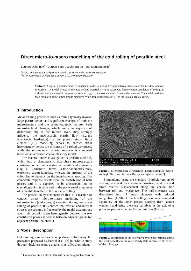
The material under investigation is pearlitic steel [1],
which has a characteristic dual-phase microstructure
consisting of a thin stacking of ferrite and cementite
(Fig. 1). Cementite forms a-few-nanometers-thick,
extremely strong lamellae, whereas the strength of the
softer ferrite depends on the inter-lamellar spacing. The
composite response results from the contribution of both phases and it is expected to be anisotropic due to
crystallographic texture and to the preferential alignment
of cementite lamellae in the course of rolling.
The present study demonstrates that it is feasible to
conduct direct micro-to-macro modelling of the
microstructure (and strength) evolution during multi-pass
rolling of pearlite. It is shown that texture and internal
stresses are strongly influenced by the model assumptions
about microscopic strain heterogeneity between the two
constitutive phases as well as between adjacent grains (or
adjacent pearlite “colonies”).
2 Model description
Cold rolling simulations were performed following the
procedure proposed by Bardel et al. [2] in order to study
through-thickness texture gradients in rolled aluminium.
Figure 1. Microstructure of “patented” pearlite samples (before rolling). The cementite lamellae appear lighter. From [1].
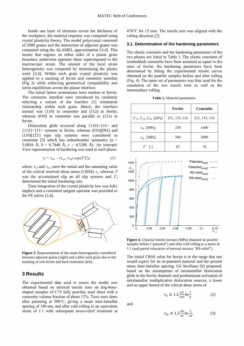
Simulations, using the standard (implicit version of abaqus), assumed plane strain deformation, rigid rolls and
finite relative displacement along the contact line
between roll and workpiece. The half-thickness was
discretized into 11 linear elements with reduced
integration (C2D4R). Each rolling pass was simulated
separately of the other passes, starting from square
elements and using the state variables at the exit of a
previous pass as input for the current pass (Fig. 2).
Figure 2. Illustration of the heterogeneity of shear strains across the workpiece thickness when steady state is detected at the exit of the rolling gap.
MATEC Web of Conferences
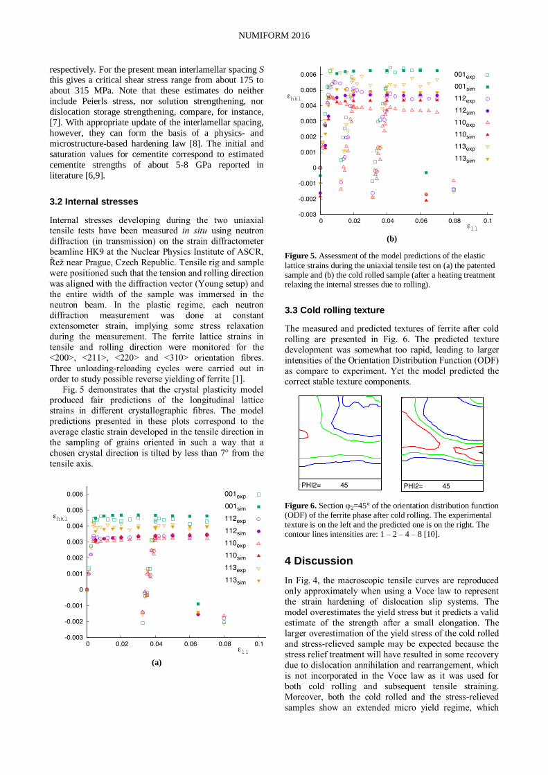
Inside one layer of elements across the thickness of
the workpiece, the material response was computed using
crystal plasticity theory. The model polycrystal consisted
of 2000 grains and the interaction of adjacent grains was
computed using the ALAMEL approximation [3-4]. This
means that regions on either sides of a planar grain
boundary underwent opposite shear superimposed to the
macroscopic strain. The amount of the local strain
heterogeneity was computed by minimizing the plastic
work [2,4]. Within each grain crystal plasticity was
applied to a stacking of ferrite and cementite lamellae (Fig. 3) while enforcing geometrical compatibility and
stress equilibrium across the planar interface.
The initial lattice orientations were random in ferrite.
The cementite lamellae were introduced by randomly
selecting a variant of the Isaichev [1] orientation
relationship within each grain. Hence, the interface
normal was (110) in cementite and (112) in ferrite,
whereas (010) in cementite was parallel to (111) in
ferrite.
Dislocation glide occurred along {110}<111> and
{112}<111> systems in ferrite, whereas (010)[001] and
(110)[ ̅ ] type slip systems were considered in
cementite [5] which has orthorhombic symmetry (a =
5.0816 Å, b = 6.7446 Å, c = 4.5206 Å). An isotropic Voce representation of hardening was used in each phase:
c = sat – (sat–c0) exp(/0) (1)
where c0 and sat were the initial and the saturating value
of the critical resolved shear stress (CRSS) c, whereas
was the accumulated slip on all slip systems and 0 determined the initial hardening rate.
Time integration of the crystal plasticity law was fully
implicit and a consistent tangent operator was provided to
the FE solver [2,4].
Figure 3. Representation of the strain heterogeneity considered
between adjacent grains (right) and within each grain due to the
stacking of soft ferrite and hard cementite (left).
3 Results
The experimental data used to assess the model was
obtained based on uniaxial tensile tests on dog-bone-
shaped samples of C75 fully pearlitic steel sheet with a
cementite volume fraction of about 12%. Tests were done
after patenting at 500°C, giving a mean inter-lamellar
spacing of 140 nm, and after cold rolling to an equivalent
strain of 1.1 with subsequent stress-relief treatment at
470°C for 15 min. The tensile axis was aligned with the
rolling direction [2].
3.1. Determination of the hardening parameters
The elastic constants and the hardening parameters of the
two phases are listed in Table 1. The elastic constants of
(embedded) cementite have been assumed as equal to the
ones of ferrite; the hardening parameters have been determined by fitting the experimental tensile curves
obtained on the pearlite samples before and after rolling
(Fig. 4). The same set of parameters was thus used for the
simulation of the two tensile tests as well as the
intermediary rolling.
Table 1. Material parameters.
Ferrite Cementite
C11, C12, C44 [GPa] 231, 135, 116 231, 135, 116
c0 [MPa] 250 1600
sat [MPa] 380 2000
[-] 65 10
Figure 4. Uniaxial tensile stresses [MPa] obtained on pearlite samples before (“patented”) and after cold rolling to a strain of
1.1 (and partial relaxation of internal stresses “RS-relief”).
The initial CRSS value for ferrite is in the range that one would expect for an as-patented material and the present
mean inter-lamellar spacing: Gil Sevillano [6] proposed,
based on the assumptions of intralamellar dislocation
glide in the ferrite channels and predominant activation of
intralamellar multiplicative dislocation sources, a lower
and an upper bound of the critical shear stress of
(2)
and
(3)
NUMIFORM 2016
respectively. For the present mean interlamellar spacing S this gives a critical shear stress range from about 175 to
about 315 MPa. Note that these estimates do neither
include Peierls stress, nor solution strengthening, nor
dislocation storage strengthening, compare, for instance,
[7]. With appropriate update of the interlamellar spacing,
however, they can form the basis of a physics- and
microstructure-based hardening law [8]. The initial and
saturation values for cementite correspond to estimated
cementite strengths of about 5-8 GPa reported in
literature [6,9].
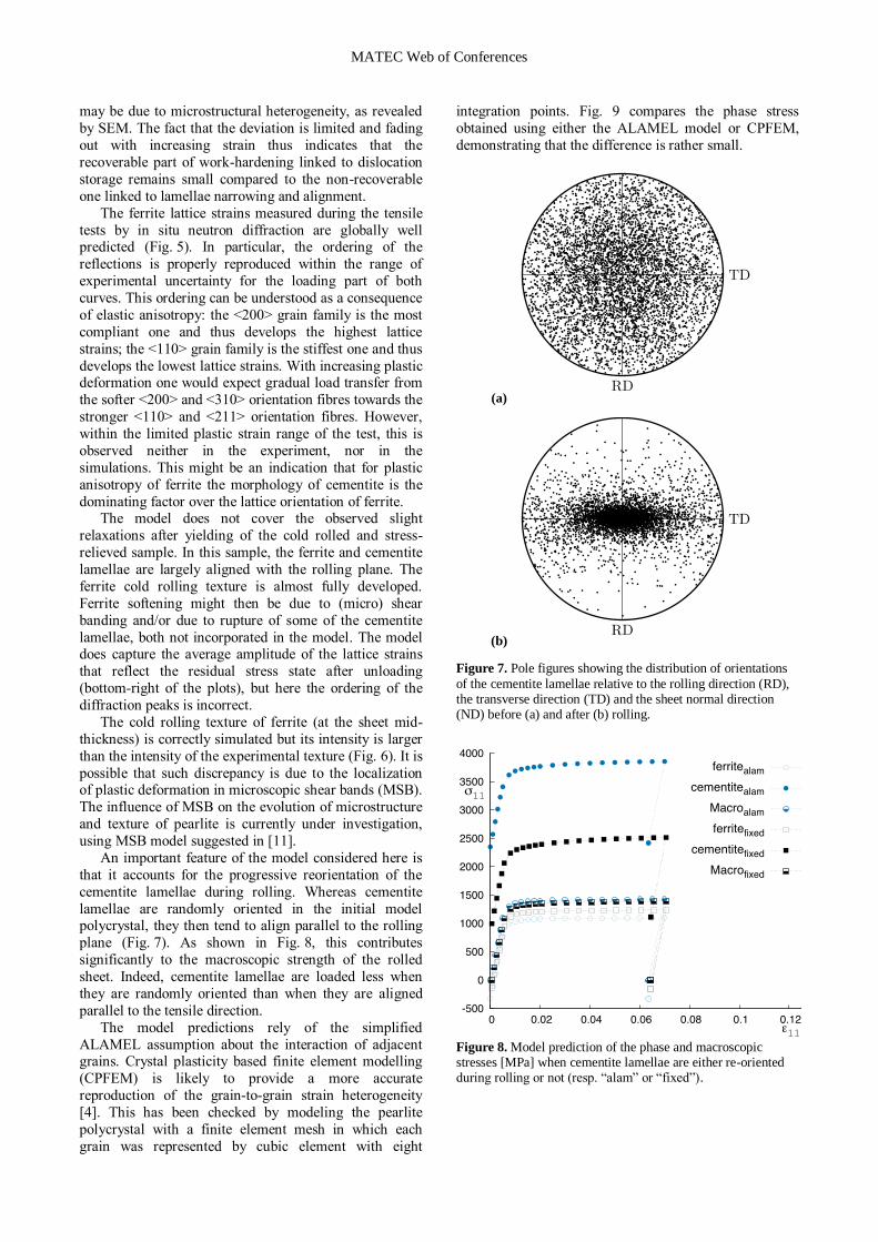
3.2 Internal stresses
Internal stresses developing during the two uniaxial tensile tests have been measured in situ using neutron
diffraction (in transmission) on the strain diffractometer
beamline HK9 at the Nuclear Physics Institute of ASCR,
Řež near Prague, Czech Republic. Tensile rig and sample
were positioned such that the tension and rolling direction
was aligned with the diffraction vector (Young setup) and
the entire width of the sample was immersed in the
neutron beam. In the plastic regime, each neutron diffraction measurement was done at constant
extensometer strain, implying some stress relaxation
during the measurement. The ferrite lattice strains in
tensile and rolling direction were monitored for the
<200>, <211>, <220> and <310> orientation fibres.
Three unloading-reloading cycles were carried out in
order to study possible reverse yielding of ferrite [1].
Fig. 5 demonstrates that the crystal plasticity model produced fair predictions of the longitudinal lattice
strains in different crystallographic fibres. The model
predictions presented in these plots correspond to the
average elastic strain developed in the tensile direction in
the sampling of grains oriented in such a way that a
chosen crystal direction is tilted by less than 7° from the
tensile axis.
(a)
(b)
Figure 5. Assessment of the model predictions of the elastic
lattice strains during the uniaxial tensile test on (a) the patented sample and (b) the cold rolled sample (after a heating treatment relaxing the internal stresses due to rolling).
3.3 Cold rolling texture
The measured and predicted textures of ferrite after cold
rolling are presented in Fig. 6. The predicted texture
development was somewhat too rapid, leading to larger
intensities of the Orientation Distribution Function (ODF)
as compare to experiment. Yet the model predicted the
correct stable texture components.
Figure 6. Section 2=45° of the orientation distribution function (ODF) of the ferrite phase after cold rolling. The experimental texture is on the left and the predicted one is on the right. The contour lines intensities are: 1 – 2 – 4 – 8 [10].
4 Discussion
In Fig. 4, the macroscopic tensile curves are reproduced
only approximately when using a Voce law to represent
the strain hardening of dislocation slip systems. The
model overestimates the yield stress but it predicts a valid
estimate of the strength after a small elongation. The larger overestimation of the yield stress of the cold rolled
and stress-relieved sample may be expected because the
stress relief treatment will have resulted in some recovery
due to dislocation annihilation and rearrangement, which
is not incorporated in the Voce law as it was used for
both cold rolling and subsequent tensile straining.
Moreover, both the cold rolled and the stress-relieved
samples show an extended micro yield regime, which
MATEC Web of Conferences
may be due to microstructural heterogeneity, as revealed
by SEM. The fact that the deviation is limited and fading
out with increasing strain thus indicates that the
recoverable part of work-hardening linked to dislocation
storage remains small compared to the non-recoverable
one linked to lamellae narrowing and alignment.
The ferrite lattice strains measured during the tensile
tests by in situ neutron diffraction are globally well predicted (Fig. 5). In particular, the ordering of the
reflections is properly reproduced within the range of
experimental uncertainty for the loading part of both
curves. This ordering can be understood as a consequence
of elastic anisotropy: the <200> grain family is the most
compliant one and thus develops the highest lattice
strains; the <110> grain family is the stiffest one and thus
develops the lowest lattice strains. With increasing plastic deformation one would expect gradual load transfer from
the softer <200> and <310> orientation fibres towards the
stronger <110> and <211> orientation fibres. However,
within the limited plastic strain range of the test, this is
observed neither in the experiment, nor in the
simulations. This might be an indication that for plastic
anisotropy of ferrite the morphology of cementite is the
dominating factor over the lattice orientation of ferrite. The model does not cover the observed slight
relaxations after yielding of the cold rolled and stress-
relieved sample. In this sample, the ferrite and cementite
lamellae are largely aligned with the rolling plane. The
ferrite cold rolling texture is almost fully developed.
Ferrite softening might then be due to (micro) shear
banding and/or due to rupture of some of the cementite
lamellae, both not incorporated in the model. The model does capture the average amplitude of the lattice strains
that reflect the residual stress state after unloading
(bottom-right of the plots), but here the ordering of the
diffraction peaks is incorrect.
The cold rolling texture of ferrite (at the sheet mid-
thickness) is correctly simulated but its intensity is larger
than the intensity of the experimental texture (Fig. 6). It is
possible that such discrepancy is due to the localization of plastic deformation in microscopic shear bands (MSB).
The influence of MSB on the evolution of microstructure
and texture of pearlite is currently under investigation,
using MSB model suggested in [11].
An important feature of the model considered here is
that it accounts for the progressive reorientation of the
cementite lamellae during rolling. Whereas cementite
lamellae are randomly oriented in the initial model polycrystal, they then tend to align parallel to the rolling
plane (Fig. 7). As shown in Fig. 8, this contributes
significantly to the macroscopic strength of the rolled
sheet. Indeed, cementite lamellae are loaded less when
they are randomly oriented than when they are aligned
parallel to the tensile direction.
The model predictions rely of the simplified
ALAMEL assumption about the interaction of adjacent grains. Crystal plasticity based finite element modelling
(CPFEM) is likely to provide a more accurate
reproduction of the grain-to-grain strain heterogeneity
[4]. This has been checked by modeling the pearlite
polycrystal with a finite element mesh in which each
grain was represented by cubic element with eight
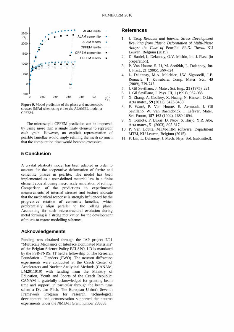
integration points. Fig. 9 compares the phase stress
obtained using either the ALAMEL model or CPFEM,
demonstrating that the difference is rather small.
(a)
(b)
Figure 7. Pole figures showing the distribution of orientations
of the cementite lamellae relative to the rolling direction (RD), the transverse direction (TD) and the sheet normal direction (ND) before (a) and after (b) rolling.
Figure 8. Model prediction of the phase and macroscopic stresses [MPa] when cementite lamellae are either re-oriented during rolling or not (resp. “alam” or “fixed”).
NUMIFORM 2016
Figure 9. Model prediction of the phase and macroscopic stresses [MPa] when using either the ALAMEL model or CPFEM.
The microscopic CPFEM prediction can be improved
by using more than a single finite element to represent
each grain. However, an explicit representation of
pearlite lamellae would imply refining the mesh so much
that the computation time would become excessive.
5 Conclusion
A crystal plasticity model has been adapted in order to
account for the cooperative deformation of ferrite and
cementite phases in pearlite. The model has been implemented as a user-defined material law in a finite
element code allowing macro scale simulation of rolling.
Comparison of the predictions to experimental
measurements of internal stresses and texture indicate
that the mechanical response is strongly influenced by the
progressive rotation of cementite lamellae, which
preferentially align parallel to the rolling plane.
Accounting for such microstructural evolution during metal forming is a strong motivation for the development
of micro-to-macro modelling schemes.
Acknowledgements
Funding was obtained through the IAP project 7/21
"Multiscale Mechanics of Interface Dominated Materials"
of the Belgian Science Policy BELSPO. LD is mandated
by the FSR-FNRS, JT held a fellowship of The Research
Foundation - Flanders (FWO). The neutron diffraction experiments were conducted at the Czech Center of
Accelerators and Nuclear Analytical Methods (CANAM,
LM2011019) with funding from the Ministry of
Education, Youth and Sports of the Czech Republic.
CANAM is gratefully acknowledged for granting beam
time and support, in particular through the beam time
scientist Dr. Jan Pilch. The European Union's Seventh
Framework Program for research, technological
development and demonstration supported the neutron
experiments under the NMI3-II Grant number 283883.
References
1. J. Tacq, Residual and Internal Stress Development
Resulting from Plastic Deformation of Multi-Phase
Alloys: the Case of Pearlite. Ph.D. Thesis, KU
Leuven, Belgium (2015).
2. D. Bardel, L. Delannay, O.V. Mishin, Int. J. Plast. (in
preparation).
3. P. Van Houtte, S. Li, M. Seefeldt, L. Delannay, Int.
J. Plast., 21 (2005), 589-624.
4. L. Delannay, M.A. Melchior, J.W. Signorelli, J-F.
Remacle, T. Kuwabara, Comp. Mater. Sci., 45
(2009), 739-743. 5. J. Gil Sevillano, J. Mater. Sci. Eng., 21 (1975), 221.
6. J. Gil Sevillano, J. Phys. III, 1 (1991), 967-988.
7. X. Zhang, A. Godfrey, X. Huang, N. Hansen, Q.Liu,
Acta mater., 59 (2011), 3422-3430.
8. P. Watté, P. Van Houtte, E. Aernoudt, J. Gil
Sevillano, W. Van Raemdonck, I. Lefever, Mater.
Sci. Forum, 157-162 (1994), 1689-1694.
9. Y. Tomota, P. Lukáš, D. Neov, S. Harjo, Y.R. Abe,
Acta mater., 51 (2003), 805-817. 10. P. Van Houtte, MTM-FHM software, Department
MTM, KU Leuven, Belgium (2015).
11. F. Lin, L. Delannay, J. Mech. Phys. Sol. (submitted).