direct immersion cooling via nucleate boiling of hfe-7100 .../67531/metadc699916/m2/1/high... · i...
TRANSCRIPT

APPROVED: Huseyin Bostanci, Major Professor Seifollah Nasrazadani, Committee Member Shuping Wang, Committee Member Enrique Barbieri, Chair of the Department of
Engineering Technology Costas Tsatsoulis, Dean of the College of
Engineering Mark Wardell, Dean of the Toulouse Graduate
School
DIRECT IMMERSION COOLING VIA NUCLEATE BOILING OF HFE-7100 DIELECTRIC LIQUID
ON HYDROPHOBIC AND HYDROPHILIC SURFACES
Nihal E. Joshua
Thesis Prepared for the Degree of
MASTER OF SCIENCE
UNIVERSITY OF NORTH TEXAS
December 2014

Joshua, Nihal E. Direct Immersion Cooling via Nucleate Boiling of HFE-7100 Dielectric Liquid
on Hydrophobic and Hydrophilic Surfaces. Masters of Science (Engineering Systems - Mechanical
Systems), December 2014, 57 pp., 4 tables, 25 figures, references, 21 numbered titles.
This study experimentally investigated the effect of hydrophobic and hydrophilic surfaces
characteristics on nucleate boiling heat transfer performance for the application of direct
immersion cooling of electronics. A dielectric liquid, HFE – 7100 was used as the working fluid in
the saturated boiling tests. Twelve types of 1-cm2 copper heater samples, simulating high heat
flux components, featured reference smooth copper surface, fully and patterned hydrophobic
surface and fully and patterned hydrophilic surfaces. Hydrophobic samples were prepared by
applying a thin Teflon coating following photolithography techniques, while the hydrophilic TiO2
thin films were made through a two step approach involving layer by layer self assembly and
liquid phase deposition processes. Patterned surfaces had circular dots with sizes between 40 –
250 µm. Based on additional data, both hydrophobic and hydrophilic surfaces improved nucleate
boiling performance that is evaluated in terms of boiling incipience, heat transfer coefficient and
critical heat flux (CHF) level. The best results, considering the smooth copper surface as the
reference, were achieved by the surfaces that have a mixture of hydrophobic/hydrophilic
coatings, providing: (a) early transition to boiling regime and with eliminated temperature
overshoot phenomena at boiling incipience, (b) up to 58.5% higher heat transfer coefficients,
and (c) up to 47.4% higher CHF levels. The studied enhanced surfaces therefore demonstrated a
practical surface modification method for heat transfer enhancement in immersion cooling
applications.

Copyright 2014
by
Nihal E. Joshua
ii
ACKNOWLEDGMENTS
I would like to express my gratitude to my major professor and advisor Dr. H. Bostanci
for his immense support, and encouragement throughout this research. His continued
guidance, suggestions and inspiration have enabled me to complete this thesis. I consider
myself very fortunate to have had the opportunity to work with him.
I would like to thank Dr. S. Nasrazadani and Dr. S. Wang for serving as committee
members and for their valuable comments.
I would also like to thank Dinesh K. Ajakumar, a former student, for his help and
contribution in the fabrication of enhanced surfaces.
A special thanks to my wife Elizabeth for her support and encouragement throughout
my research. I would also like to thank my parents and in-laws for their prayers and moral
support.
iii

TABLE OF CONTENTS
Page
ACKNOWLEDGMENTS ..................................................................................................................... iii
LIST OF TABLES ................................................................................................................................ vi
LIST OF FIGURES ............................................................................................................................. vii
LIST OF ACRONYMS/ABBREVIATIONS ............................................................................................. ix
CHAPTER 1 INTRODUCTION ............................................................................................................ 1
CHAPTER 2 LITERATURE REVIEW .................................................................................................... 6
2.1 Inception of Boiling ....................................................................................................... 8
2.2 Model of Ebullition Cycle ............................................................................................ 10
CHAPTER 3 EXPERIMENTAL SETUP AND PROCEDURE .................................................................. 17
3.1 Experimental Setup .................................................................................................... 17
3.2 Working Fluid .............................................................................................................. 19
3.3 Test Section ................................................................................................................ 20
3.4 Reference and Enhanced Boiling Surfaces ................................................................. 23
3.6 Test Conditions and Procedure .................................................................................. 27
3.7 Experimental Uncertainties ........................................................................................ 31
CHAPTER 4 RESULTS AND DISCUSSIONS ...................................................................................... 32
4.1 Reference Surface ....................................................................................................... 32
4.2 Hydrophobic Surfaces ................................................................................................. 35
4.3 Hydrophilic Surface ..................................................................................................... 41
4.4 Hydrophobic/Hydrophilic Surface .............................................................................. 46
iv

4.5 Overall Performance Comparison .............................................................................. 49
CHAPTER 5 CONCLUSIONS ............................................................................................................ 52
5.1 Concluding Remarks ................................................................................................... 52
5.2 Recommendations for Future Research ..................................................................... 53
REFERENCES .................................................................................................................................. 55
v

LIST OF TABLES
Page
Table 1: Comparison of the Common Cooling Methods ............................................................ 3
Table 2: Comparison of the Physical Properties of Various Liquids ......................................... 19
Table 3: Heater Description ...................................................................................................... 22
Table 4: Performance Summary of Heater Surfaces ................................................................ 51
vi

LIST OF FIGURES
Page
Figure 1: Growing power levels of electronic processors over time. .................................... 2
Figure 2: Graph showing no. of transmitters increasing in a chip yearly .............................. 2
Figure 3: Boiling curve ............................................................................................................ 7
Figure 4: Surface with cavities and grooves .......................................................................... 9
Figure 5: Bubble in equilibrium .............................................................................................. 9
Figure 6: Ebullition cycle ...................................................................................................... 10
Figure 7: Schematic diagram of the experimental setup. .................................................... 18
Figure 8: (a) Heater boiling surface side, (b) resistor side, (c) overall assembly in adapter plate. ........................................................................................................ 20
Figure 9: Pattern design hydrophobic and hydrophilic surface coatings. ........................... 22
Figure 10: Contact angle measurement of water on reference, plain-smooth copper surface ................................................................................................................... 25
Figure 11: LabView front end. ................................................................................................ 29
Figure 12: LabViewblock diagram. ......................................................................................... 30
Figure 13: Boiling curves of the reference surfaces. ............................................................. 34
Figure 14: HTC of reference surfaces as a function of heat flux. .......................................... 35
Figure 15: Boiling curves of reference surface and fully hydrophobic surface. .................... 36
Figure 16: Boiling curves of reference and patterned hydrophobic surfaces. ...................... 38
Figure 17: Surface superheat (a) and temperature overshoot (b) at boiling incipience of reference and patterned hydrophobic surfaces ................................................... 39
Figure 18: HTC of reference and hydrophobic surfaces as a function of heat flux. .............. 41
Figure 19: Boiling curves of reference surface and fully hydrophilic surface. ....................... 42
vii

Figure 20: Boiling curves of reference surface and patterned hydrophilic surfaces. ............ 44
Figure 21: HTC of reference and hydrophilic surfaces as a function of heat flux. ................ 45
Figure 22: Boiling curves of reference surface and patterned hydrophobic/hydrophilic surfaces. ................................................................................................................ 47
Figure 23: HTC of reference and hydrophobic/hydrophilic surfaces as a function of heat flux. ............................................................................................................... 48
Figure 24: Boiling curves of reference and enhanced surfaces as a function of heat flux. .. 49
Figure 25: HTC of reference and enhanced surfaces as a function of heat flux. .................. 50
viii

LIST OF ACRONYMS/ABBREVIATIONS
A Area, cm2
CHF Critical heat flux, W/cm2
h Heat transfer coefficient, W/m2° C
I Current, A
K Heater wall thermal conductivity, W/m°C
Psat Saturation pressure, kPa
q” Heat flux, W/cm2
Tsat Saturation temperature, °C
Tsurf Surface temperature, °C
TCavg Average thermocouple reading, °C
V Voltage, V
σ Surface tension, N/m
Tsup Superheated liquid
Pambient Ambient pressure
Rb Radius of bubbles
ix

CHAPTER 1
INTRODUCTION
Complexity of electronic components has changed dramatically over the past several
decades. An increase in complexity has caused a simultaneous increase in power dissipation
and clock speeds. It is crucial to keep the temperatures of these components within the
specifically designed ranges. High temperatures can cause thermal stresses, break the soldered
joints in the system and decrease the lifespan of the components drastically. It is thus
necessary to actively cool systems to maintain their temperatures at desired levels for reliable
and efficient operation.
In today’s technological trend, devices continue to evolve with greater power and
denser volume as illustrated in Figure 1. Higher levels of integration in semiconductors, along
with smaller devices and faster speeds have led to higher heat generation and higher heat
densities. Intel co-founder Gordon Moore famously stated, what is known today as Moore's
Law, that the “number of transistors on a chip will double approximately every 2 years.” Due to
such rapid increase in complexity, functionality, higher operating speeds and reduction in
overall size, thermal management plays a vital role in the designing of components from circuits
to systems in achieving high reliability and performance. In certain critical applications, thermal
management also affects the size and weight of the overall system.
1

Figure 1: Growing power levels of electronic processors over time. [1]
Figure 2: Graph showing no. of transmitters increasing in a chip yearly. [2]
2

Thermal management technologies are divided into two distinct groups:
• Passive thermal management - Cooling technologies that depend on the
thermodynamics of conduction, convection and radiation to transfer heat. Thermal
interface materials, heat spreaders and heat sinks are a few passive technologies.
• Active thermal management - Cooling technologies that use external energy to enhance
heat transfer. Forced air cooling with fans, thermoelectric coolers and spray cooling are
some of the active technologies.
Among these various technologies, forced air cooling, generally implemented with heat
sinks and fans, is an active thermal management technique that has been a predominant
method of cooling for a long time. However due to rising heat flux levels (heat load per unit
area), it is getting rather difficult for this conventional method to efficiently cool the new
systems and maintain temperature levels for reliable operation. An alternative method to
conventional air cooling is the liquid cooling that provides higher heat transfer performance. As
shown in table 1, liquid cooling with water attains up to 63.4% higher heat transfer coefficient,
h, compared to forced air cooling and is capable of removing much higher heat loads.
Table 1
Comparison of the Common Cooling Methods [3]
Air Cooling - Natural Convection
Air Cooling - Forced Convection
Liquid Cooling with Water
Immersion Cooling
h = 5 - 30 W/m2 K h = 20 - 400 W/m2 K h = 100-1600 W/m2 K h=800-10000 W/m2 K Q = 2 - 9 W Q = 6 - 120 W Q = 30 - 480 W Q = 240 - 3000 W
Free convection Free + Forced convection
Forced convection Free convection
3

Immersion cooling is another promising cooling method that achieves even better heat
transfer capabilities. In immersion cooling the major heat transfer mode is, nucleate boiling
that utilizes liquid-vapor phase change mechanism. Phase change techniques continue to be of
interest in the area of thermal management due to their inherent advantages such as providing
high heat flux removal capability and nearly uniform temperature distribution on cooled
surfaces. In immersion cooling the heat generating device is immersed in a stagnant pool of
working fluid, and large amounts of heat are absorbed as the liquid changes phase to vapor
with a relatively low temperature difference between the device and the pool. Selection of the
appropriate coolant is critical for direct immersion cooling, which requires chemical inertness
and compatibility, high dielectric strength, safe handling, and low environmental impact. When
a dielectric liquid is used as the working fluid, it can come into direct contact with every surface
of the component. This method allows much higher heat flux dissipation than air cooling (more
than 50% as indicated in Table 1) and is a good choice for high performance computers, super
computers and compact devices generating large amounts of heat.
Many nucleate boiling studies have been conducted with dielectric liquids, such as 3M™
Fluorinert™ Electronic Liquids FC-72, FC-86 and FC–87, targeted for electronics cooling
applications [4]. Current research efforts have been focused on the recently developed
dielectric liquids, such as 3M’s Novec Engineered Fluids HFE-7100 and HFE-7200. The Novec
fluids still share the same desired properties of Fluorinerts, and additionally offer two improved
properties that are important in terms of their environmental impact, namely, low global
warming potential (GWP), and zero ozone depletion potential (ODP). The Novec dielectric fluids
provide dependable performance and require little maintenance. Since they possess high
4
resistivity, they do not damage electronic equipment or integrated circuits in the event of leak
or failure. The chemical inertness and non corrosivity of the fluids make them safe for workers
to handle.
An important thrust in the current nucleate boiling research in the context of thermal
management is the enhanced heat transfer surfaces. Such surfaces improve the heat transfer
performance measured by earlier transition to boiling, higher heat transfer coefficient, and
higher critical heat flux that defines the practical heat flux limit. The goal of the current study
was to experimentally investigate the effect of hydrophobic and hydrophilic surfaces in the
nucleate boiling performance. The HFE-7100 dielectric liquid was selected as the working fluid,
and a 1-cm2 copper test section, simulating a high power electronic device, was tested under
saturation boiling conditions at near atmospheric pressures. The performance of the carefully
prepared sample surfaces was compared to that of a reference, untreated smooth surface to
determine their effect on nucleate boiling heat transfer, and their potential use in direct
immersion cooling applications.
5

CHAPTER 2
LITERATURE REVIEW
The previous section discussed how conventional methods were not capable of keeping
up with the emerging trends in technology. Thus, there was a need for a greatly improved and
more efficient means of cooling. Boiling is a promising mode of heat transfer and could be one
of the most effective solutions for the future. This chapter explains the boiling process and the
many studies that have been conducted thus far in this field of research.
Boiling is a phase change process wherein vapor bubbles are formed on the surface that
is being heated. Nucleate boiling is an efficient method used for transferring heat and can be
used in many highly dense electronic components. Since it is a very complex process and
because of the number of variables involved, studies are presently being conducted to better
understand the boiling process. Studies for pool boiling go as far back as 1934 when Nukiyama
ran an experiment and plotted the boiling curve for the very first time. He boiled water to its
saturation temperature over Nichrome wire. Then, by calibrating the resistance of the wire as a
function of temperature, he obtained heat flux and temperature from the observed voltage and
current. At a very high heat flux, the wire melted since it surpassed the Critical heat flux (CHF).
He then ran a second experiment with a platinum wire and successfully plotted a boiling curve
with ∆T vs. q”. In 1937, Drew and Mueller ran a successful experiment in boiling water at
saturated temperature and at atmospheric pressure and were able to plot the boiling curve, the
only change being that the curve was rotated to q" vs. ∆T. Pool boiling is divided into five
regimes which are natural convection, nucleate boiling, critical heat flux, transitional boiling
regime and film boiling.
6

Figure 3: Boiling curve. [6]
The boiling curve in Figure 3shows the heat flux input against the wall superheat for a
test piece (heater) submerged in a pool of liquid. The wall superheat ∆T is the difference
between the heater temperature and the saturated temperature of the liquid at pressure of the
existing system. The curve that is being plotted is for the heater wherein the heat input to the
heater is being controlled. As the heat flux to the heater is increased, natural convection is the
first mode of heat transfer. Natural convection is a mechanism where the motion of the fluid is
7

not generated by an external source, but by differences in the density of the fluid. When the
fluid surrounding the heat source receives heat, the fluid rises and is replaced by cooler fluid
from the surrounding area.
Natural convection follows the principle of buoyancy as a result of the differences
caused in the fluid density. At a certain input of heat flux, bubbles develop on the heater
surface. This is the starting point for nucleate boiling. Nucleate boiling regime embraces the
two distinct regimes. The first is the region of isolated bubbles where bubbles rise from isolated
nucleation sites and as q and ∆T are increased, more and more sites are activated. The second
is the region of slugs and columns where when the active sites become very numerous, the
bubbles merge into one another and a totally different vapor path is developed. The vapors
formed at the surface merge into jets that feed overhead bubbles or slugs of vapor. Critical heat
flux is the point up to which the system can be operated safely and wherein nucleate boiling is
fully developed. After the point of critical heat flux, most of the heater surface is rapidly
covered with vapor. The surface is insulated and the surface temperature rises rapidly [6]. The
region where the heater surface is insulated with vapor is known as the transition boiling. In
this region, heat flux decreases drastically since the liquid takes in huge portions of heat,
causing a vapor blanket. Due to this blanket, the surrounding liquid finds it difficult to reach the
heater, causing a decrease in the heat transfer rate.
2.1 Inception of Boiling
Surfaces are not smooth as they seem to a human eye. There are always tiny grooves on
the surfaces created by chattering and bouncing during machining.
8
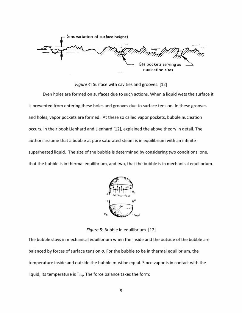
Figure 4: Surface with cavities and grooves. [12]
Even holes are formed on surfaces due to such actions. When a liquid wets the surface it
is prevented from entering these holes and grooves due to surface tension. In these grooves
and holes, vapor pockets are formed. At these so called vapor pockets, bubble nucleation
occurs. In their book Lienhard and Lienhard [12], explained the above theory in detail. The
authors assume that a bubble at pure saturated steam is in equilibrium with an infinite
superheated liquid. The size of the bubble is determined by considering two conditions: one,
that the bubble is in thermal equilibrium, and two, that the bubble is in mechanical equilibrium.
Figure 5: Bubble in equilibrium. [12]
The bubble stays in mechanical equilibrium when the inside and the outside of the bubble are
balanced by forces of surface tension σ. For the bubble to be in thermal equilibrium, the
temperature inside and outside the bubble must be equal. Since vapor is in contact with the
liquid, its temperature is Tsup. The force balance takes the form:
9
𝑅𝑅𝑏𝑏 = 2𝜎𝜎𝑃𝑃𝑠𝑠𝑠𝑠𝑠𝑠𝑎𝑎𝑎𝑎𝑇𝑇𝑠𝑠𝑠𝑠𝑠𝑠−𝑃𝑃𝑠𝑠𝑎𝑎𝑎𝑎𝑎𝑎𝑎𝑎𝑎𝑎𝑠𝑠
(1)
If the radius of the bubble is smaller than the value calculated in the force balance
equation mentioned above, the surface tension overbalances and thus the vapor condenses
inside at high pressure and the bubble collapses. If the radius is larger than the equation
specified, liquid at the interface evaporates and the bubble begins to grow. Research in the
field of nucleate boiling has shown that as heater surface temperature increases the
equilibrium radius decreases and thus small nucleation sites are activated for bubble growth.
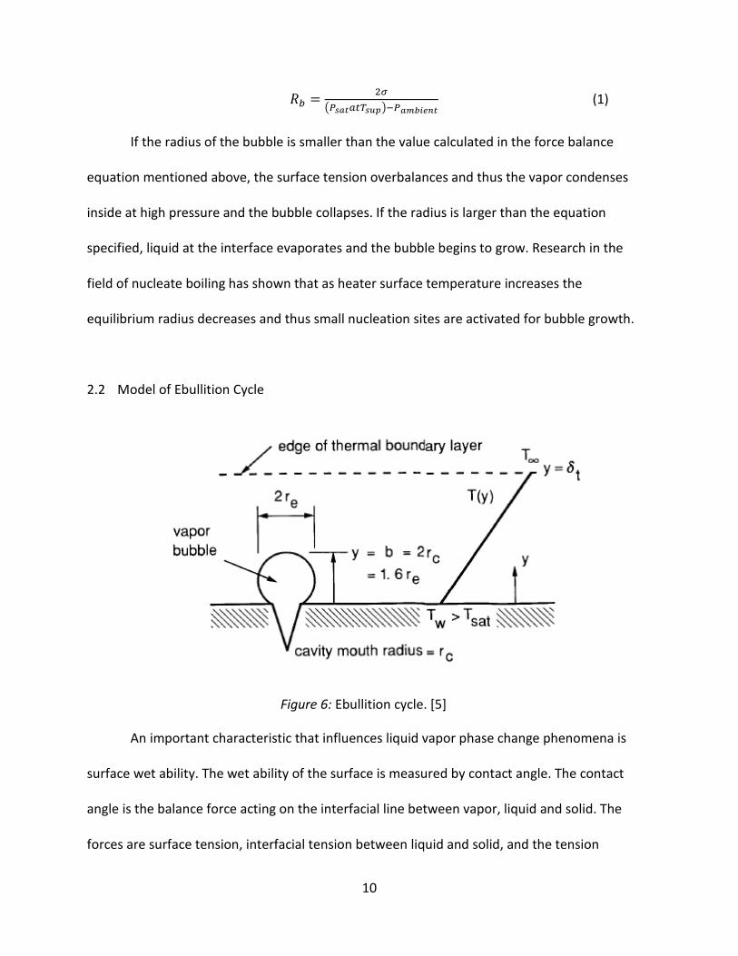
2.2 Model of Ebullition Cycle
An important characteristic that influences liquid vapor phase change phenomena is
surface wet ability. The wet ability of the surface is measured by contact angle. The contact
angle is the balance force acting on the interfacial line between vapor, liquid and solid. The
forces are surface tension, interfacial tension between liquid and solid, and the tension
Figure 6: Ebullition cycle. [5]
10
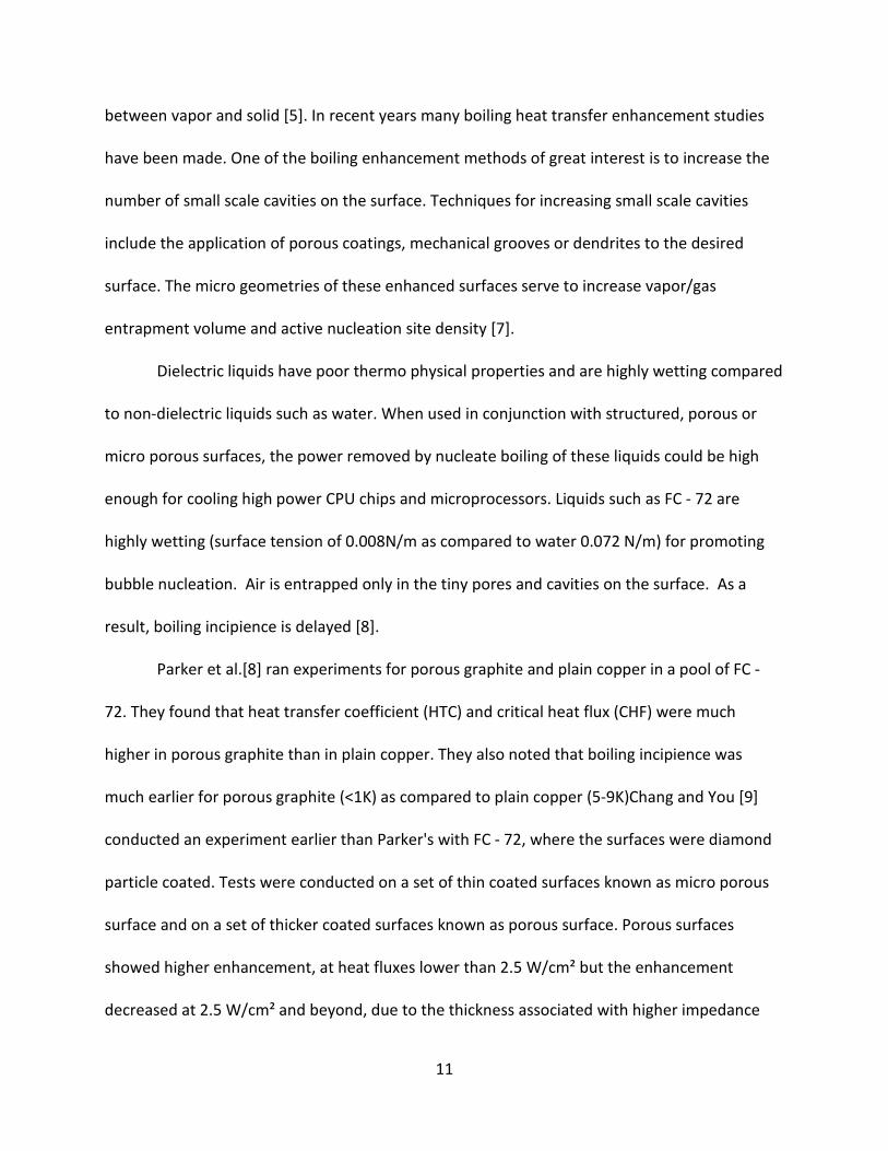
between vapor and solid [5]. In recent years many boiling heat transfer enhancement studies
have been made. One of the boiling enhancement methods of great interest is to increase the
number of small scale cavities on the surface. Techniques for increasing small scale cavities
include the application of porous coatings, mechanical grooves or dendrites to the desired
surface. The micro geometries of these enhanced surfaces serve to increase vapor/gas
entrapment volume and active nucleation site density [7].
Dielectric liquids have poor thermo physical properties and are highly wetting compared
to non-dielectric liquids such as water. When used in conjunction with structured, porous or
micro porous surfaces, the power removed by nucleate boiling of these liquids could be high
enough for cooling high power CPU chips and microprocessors. Liquids such as FC - 72 are
highly wetting (surface tension of 0.008N/m as compared to water 0.072 N/m) for promoting
bubble nucleation. Air is entrapped only in the tiny pores and cavities on the surface. As a
result, boiling incipience is delayed [8].
Parker et al.[8] ran experiments for porous graphite and plain copper in a pool of FC -
72. They found that heat transfer coefficient (HTC) and critical heat flux (CHF) were much
higher in porous graphite than in plain copper. They also noted that boiling incipience was
much earlier for porous graphite (<1K) as compared to plain copper (5-9K)Chang and You [9]
conducted an experiment earlier than Parker's with FC - 72, where the surfaces were diamond
particle coated. Tests were conducted on a set of thin coated surfaces known as micro porous
surface and on a set of thicker coated surfaces known as porous surface. Porous surfaces
showed higher enhancement, at heat fluxes lower than 2.5 W/cm² but the enhancement
decreased at 2.5 W/cm² and beyond, due to the thickness associated with higher impedance
11

and higher thermal resistance. Significant increase in CHF was found for the micro porous
region, but that seemed to be the upper limit for CHF and no further increase in CHF was found
in porous surfaces.
A study by El-Genk and Amir[10] consisted of nucleate boiling of micro porous layers
deposited on copper substrates in a pool of PF 5060 dielectric liquid. The basic microstructure
with patterned open macro pores surrounded by fine and dense Cu dendrites forms during the
current density (3A/cm²) electrochemical deposition stage. The thicker the deposition layer, the
larger the macro pores and denser the surrounding copper dendrites. The study showed that
these enhanced copper substrates show high surface superheats when they are run for the very
first time. As tests were repeated there was little or no temperature excursion and data was
repeatable. It was observed that PF-5060 dielectric liquid used on copper micro porous copper
surface showed 40 to 70% more improvement in CHF and maximum nucleate boiling over FC -
72 on plain copper surface.
There have been quite a few studies conducted on roughened and smooth, porous and
micro porous coated surfaces along with FC – 72, but little research has been done with HFE-
7100. El-Genk and Parker[11] conducted a study on porous graphite with HFE-7100 as the
dielectric liquid. The study showed that CHF values for HFE-7100 on porous graphite were 60%
higher and the corresponding surface superheats were 25% lower than those on smooth
copper. The results demonstrated that the relative enhancements in CHF and nucleate boiling
heat flux of HFE-7100 on porous graphite are similar to earlier studies on FC-72, except that the
actual values for the nucleate boiling heat flux for the latter are lower. The study showed that
12

graphite significantly enhances nucleate boiling and the CHF of the highly wetting HFE-7100
dielectric liquid and lowers the surface superheat compared to smooth copper.
However, a study done by El-Genk et al. [4] on a smooth copper surface with HFE 7100
showed that despite the large difference between CHF values for the FC - 72 and HFE 7100
dielectric liquids, the normalized CHF values to that in the upward facing position 0° are almost
identical. Results also demonstrated that up to 24.5W/cm² could be removed from a computer
chip with smooth copper surface by saturation nucleate boiling of HFE-7100 at 0.085 MPa,
which is 57% higher than reported earlier for FC-72 at a slightly higher pressure at 0.1 MPa. In
another study, El Genk and Parker[13] investigated saturation and 10K, 20 K and 30 K sub
cooled boiling of FC-72 and HFE-7100 dielectric liquid on porous graphite at inclination angles
0° to 180°. It was observed that at low superheats (<15K), increasing surface inclination θ
increases the nucleate boiling heat flux; however, at higher superheats, nucleate boiling heat
flux decreases with increased θ. Although increasing liquid sub cooling increases the nucleate
boiling heat flux and CHF as well as the nucleate boiling heat transfer coefficients, it decreases
the total boiling heat transfer coefficients. Therefore, for electronics cooling application
saturation boiling is far superior to sub cooled boiling because of the higher heat transfer
coefficient along with the lower surface superheat. It was also observed that CHF for FC - 72
was much higher than that for HFE-7100 and their values increase with increasing liquid sub
cooling. But at saturation temperature CHF of HFE-7100 was found to be much higher than FC-
72.
Supporting El Genk and Parker's view [13] on HFE 7100 fairing over FC-72 on porous
graphite was a study done by Priarone [14] ran an experiment for FC-72 and HFE-7100 dielectric
13

liquids but on smooth copper surfaces. Heat transfer coefficients in the nucleate boiling region
and critical heat flux values proved to be respectively 25% and 40% higher for HFE-7100 than
for FC-72 in the same operating conditions. The studies above have shown excellent results
with dielectric liquids with porous graphite and micro porous surfaces deposited on copper
substrates. The deposition of such different materials on the heater surfaces may disrupt the
boiling process by changing the micro cavities density on the heater. Today the progress in
nano coating allows modifying surface topography and chemistry at nano scale. Particles of
very small size can be deposited on the heater surface. By changing the deposited particles
material, it is possible to vary the water contact angle within 0° and 180°, hence controlling wet
ability. As scale of the nucleation sites is micrometric, only the contact angle is changed while
all other boiling parameters remain constant [15]. In the past decade or so, it has become
possible to control surface wet ability to some extent by enhancing the surface. Surfaces
developed with Hydrophobic and Hydrophilic patterns have shown enhancement in boiling.
Phan et al. [16] ran sub cooled pool boiling experiments for hydrophobic and hydrophilic
coated surfaces. In hydrophobic surfaces they found that bubbles appear at the surface for a
lower heat flux compared to standard surfaces which are usually wetted. Bubbles cannot
detach from the surface and coalesce with bubbles formed at the neighboring sites. In
hydrophilic surfaces with the enhancement of surface wet ability the bubble departure
diameter increases and the bubble emission frequency decreases. Heat transfer improves with
increased wet ability and the best heat transfer is obtained either at a contact angle close to
90° or at a low contact angle close to 0°.E. Forrest et al [17] ran an experiment for hydrophobic
and hydrophilic coated surfaces with a layer by layer assembly method. They found that thin
14

film coatings that displayed hydrophobicity were found to enhance HTC by 100%. Their studies
also showed CHF enhancement in all thin film coatings to be in the range of 44% to 101%.
Amy et al.[18] ran experiments for smooth and flat surfaces with hydrophobic and
hydrophilic patterns which improve pool boiling performance in water. The enhanced surfaces
greatly improve the heat transfer coefficient (HTC) and Critical Heat Flux (CHF). Their results
showed that hydrophobic surfaces tend to increase HTC but did not enhance CHF. A hydrophilic
surface, on the other hand, enhances both HTC as well as CHF. They found out that mixing the
two surfaces that means a hydrophilic surface with hydrophobic dots known as hydrophilic
network gave the highest enhancement and enhanced CHF and HTC by 65% and 100%
respectively over a plain hydrophilic surface. On the lines of studies shown by Amy et al [18], in
their experiment Takata et al. [19]found that surface coated with (PTFE) Teflon coating gave the
best HTC in the low flux region and the overshoot of superheating was very small. In a surface
having a mixture of Teflon and TiO₂ small overshoot of superheating on the surface in boiling
onset, better heat transfer performance in nucleate boiling region and larger CHF. The earlier
paper had shown boiling enhancement for water with TiO₂ coating. Studies with TiO₂ mostly
included water as the working fluid. Wu et al. [20]performed a study to investigate the nucleate
boiling and CHF of water and FC - 72 on TiO₂ surfaces. The test piece consisted of a 1cm² copper
heater with 1 µm TiO₂ coated surface which was used in saturated and pool boiling tests of
previously mentioned working fluids. Results showed that TiO₂ coated surface increased CHF
by 50.4% and 38.2% for water and FC-72 respectively. It was hence indicated that boiling
performance depended on level of wet ability improvement.
15
Earlier research and studies have shown how dielectric liquid are efficient and more so
the much recent Novec fluid HFE-7100. Along with type of working fluid, studies have also
indicated that types of enhanced surfaces contribute to the overall heat transfer coefficient.
Additional work needs to be done in nano scale coating of surfaces along with working fluids to
quantify the cooling potential at saturation condition and develop useful correlations to better
design and implementations.
16

CHAPTER 3
EXPERIMENTAL SETUP AND PROCEDURE
This chapter describes the experimental setup and the procedure used in the current
research. The separate sections on the test setup, working fluid, heater fabrication, and test
conditions and procedures provide detailed descriptions. The chapter concludes with the
uncertainty analysis of the measurements.
3.1 Experimental Setup
The major components of the set up include a boiling chamber, a test section,
immersion heaters, a condenser, temperature and pressure sensors, a DC power supply, and a
computer controlled data acquisition (DAQ) system, as illustrated in Figure 7. The boiling
chamber contains the HFE-7100 pool and consists of two polycarbonate shells,(the outer shell
has 152mm height, 127mm outer diameter, and 6mm thick wall while the inner shell has the
same height and wall thickness, and 114mm outer diameter) and top and bottom PEEK
lids(both have 152mm diameter and 12mm thickness). The transparent, concentric
polycarbonate shells enable visual observation during the tests and also provide an insulating
air layer for the heated pool. The shells are held tightly between the two lids with the help of 5
sets of stainless steel bolts, nuts, and washers. Gaskets are placed between the lids and the
shells on both the top and bottom ends to prevent the liquid and vapor leakages of HFE-7100
through the chamber. Three compact cartridge-style immersion heaters on the bottom lid
heats the liquid pool to desired test condition through a temperature controller. The chamber
also accommodates a condenser assembly to convert the HFE-7100 vapor back into the liquid
17

and maintain the chamber pressure. This assembly involves a copper disc with extruded fins
that are mounted on to the center opening on the top lid with the help of screws. A small
integrated pump circulates water between the condenser and an air-cooled heat exchanger
fitted with two, 120mm fans to transport and finally reject the heat to the ambient. Pool
temperature is monitored using a thermocouple (TC) probe placed near the test section while
the vapor pressure is monitored using a pressure transducer on the top lid. A programmable DC
power supply provides the heat input to the test section.
Figure 7: Schematic diagram of the experimental setup.
18

3.2 Working Fluid
The working fluid selected for this study was HFE-7100 (C4F9OCH3). HFE-7100 is a
dielectric liquid manufactured by 3M Company as part for their NOVEC Engineered Fluids. Table
2 lists relevant physical properties of HFE-7100 along with another common dielectric liquid FC-
72(C6F14), and water (H2O) for comparison purposes. Local atmospheric pressure at the test
location in Denton, TX is 98.4 kPa due to its altitude of 200 m, and the thermo physical
properties are slightly different than the listed properties at 101.3 kPa. As an example, boiling
point at 98.4kPa atmospheric pressure is 60.6oC. As indicated in Table 2, HFE-7100 possesses
much lower global warming potential, and atmospheric lifetime compared to FC-72.
Table 2
Comparison of the Physical Properties of Various Liquids
Saturation physical properties (101.3kPa)
HFE - 7100 (C₄F₉OCH₃)
FC - 72 (C₆F₁₄)
Water (H₂O)
Boiling Point (° C) 61 56 99.98 Freeze Point (° C) -135 -90 0 Ave. molecular weight (g/mole) 250 338 18.0156
Liquid density (kg/m3) 1370.2 1602.2 958.3
Vapor density (kg/m3) 9.87 13.21 0.597 Liquid viscosity (kg/ms) 3.70 x 10⁻⁴ 4.33 X 10⁻⁴ 8.9 X 10⁻⁴ Liquid specific heat(J/kg K) 1255 1101 4187 Latent heat of vaporization (kJ/kg) 111.6 88 2256.7 Liquid thermal conductivity (W/mK) 0.062 0.054 0.609 Liquid surface tension (N/m) 1.019 x 10⁻² 7.93 x 10⁻³ 58.91x10⁻³ Environmental Properties Ozone Depletion Potential - ODP 0 0 Global warming Potential - GWP 320 7400 Atmospheric lifetime - ALT (yrs) 4.1 3200 Electrical Properties @ 25 ° C Dielectric strength 28 Dielectric constant 7.39 (0.1 - 10 MHz) Volume resistivity (Ω cm) 3.3 x 10⁹
19
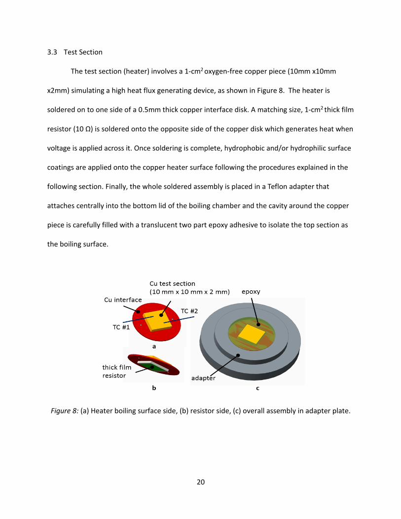
3.3 Test Section
The test section (heater) involves a 1-cm2 oxygen-free copper piece (10mm x10mm
x2mm) simulating a high heat flux generating device, as shown in Figure 8. The heater is
soldered on to one side of a 0.5mm thick copper interface disk. A matching size, 1-cm2 thick film
resistor (10 Ω) is soldered onto the opposite side of the copper disk which generates heat when
voltage is applied across it. Once soldering is complete, hydrophobic and/or hydrophilic surface
coatings are applied onto the copper heater surface following the procedures explained in the
following section. Finally, the whole soldered assembly is placed in a Teflon adapter that
attaches centrally into the bottom lid of the boiling chamber and the cavity around the copper
piece is carefully filled with a translucent two part epoxy adhesive to isolate the top section as
the boiling surface.
Figure 8: (a) Heater boiling surface side, (b) resistor side, (c) overall assembly in adapter plate.
20

Heat flux is determined from the total power supplied into the thick film resistor per
unit resistor base area as shown below.
𝑞𝑞" = 𝑉𝑉. 𝐼𝐼 𝐴𝐴
(2)
Heater temperature is monitored with two type-T thermocouples (36 AWG) embedded
halfway in the heater wall and spaced symmetrically across the 1-cm2 area as illustrated in the
figure below. Temperature spread resulted from the two thermocouples does not exceed ±
0.2°C throughout the tests indicating uniform cooling across the surface. Boiling surface
temperature is calculated as shown in equation 3 below, by extrapolating the average of two TC
readings through the known distance (half of heater wall thickness) to the surface and
assuming steady 1-D conduction through the heater wall
𝑇𝑇𝑠𝑠𝑠𝑠𝑠𝑠𝑠𝑠 = 𝑇𝑇𝑇𝑇𝑠𝑠𝑎𝑎𝑎𝑎−(𝑞𝑞".𝑥𝑥)𝑘𝑘
(3)
There are twelve types of heaters tested in this study, featuring reference, hydrophobic,
hydrophilic, and hydrophobic/hydrophilic surface characteristics. The Table 3 describes all the
tested heater types, and Table 4 shows the circular pattern design for hydrophobic and
hydrophilic surface coatings.
21

Table 3
Heater Description
No. Heater ID Heater Description (surface condition, pattern sizeD* x P* in µm) 1
2
3
4
5
6
7
8
9
10
Ref # ( )* P‡* R*
HPho # ( )
HPho_40 # ( )
HPho_100 # ( )
HPhi # ( )
HPhi_40 # ( )
HPhi_100 # ( )
HPhi _250 # ( )
HPho/HPhi_40 # ( )
HPho/HPhi_250 # ( )
Reference, smooth, no patterns
Fully hydrophobic, no patterns
Patterned hydrophobic, 40 D x 80 P
Patterned hydrophobic, 100 D x 200 P
Fully hydrophilic, no patterns
Patterned hydrophilic, 40 D x 80 P
Patterned hydrophilic, 100 D x 200 P
Patterned hydrophilic, 250 D x 500 P
Patterned hydrophobic/hydrophilic, 40 D x 80 P
Patterned hydrophobic/hydrophilic, 250 D x 500 P
* # ( ): Test heater number, P: Polished, R: Retest, D: Diameter, P: Pitch
Figure 9: Pattern design hydrophobic and hydrophilic surface coatings.
D
P
22

3.4 Reference and Enhanced Boiling Surfaces
This section details the step-by-step procedures in the preparation of test surfaces on 1-
cm2 copper substrates.
3.4.1 Reference Surfaces:
Step 1: The sample is held down and sanded on a 1200 grit sandpaper from left to right
applying medium pressure on the sample while sanding for 45 to 50 seconds.
Step 2: A polishing pad is mounted on the rotating drum at high speed and a slow and steady
jet of water keeps the drum well lubricated.
Step 3: Aluminum oxide (Al2O3) solution of 5 µm is applied on the entire pad and the copper
sample is held down on the polishing pad at medium pressure for about 30 seconds.
Step 4: Aluminum oxide (Al2O3) solution of 1 µm is applied on the entire pad, and the sample is
rotated 90oin the clockwise direction to polish the sample for about 30 seconds.
Step 5: Aluminum oxide (Al2O3) solution of 0.05 µm is applied on the entire pad, and the sample
is rotated 90oin the clockwise direction to polish the sample for about 30 seconds.
Step 6: The copper sample is held under running water to remove the particles of the
Aluminum oxide (Al2O3) solution from the surface thoroughly.
3.4.2 Fully and Patterned Hydrophobic Surfaces:
Step 1: The oven is preheated to a temperature of 90oC.
Step 2: The spin coater is set to the value Q - (2500 rpm and 30 seconds) the pump is turned on
and the heater is held in the place by vacuum.
Step 3: DuPont A1400 (Teflon) is poured on the entire heater surface with the help of a
dropper and the spin coater is turned on to complete the process of coating the surface.
23

Step 4: The sample is placed in the preheated oven and baked for 20 minutes at 90oC.
Step 5: Once the sample is baked, it undergoes a process known as the oxygen plasma for 5
cycles. (1 cycle = left to right and right to left continuous)
The next steps of the process need to be done in a dark room
Step 6: The spin coater is set to the value Q - (2000 rpm and 30 seconds) the pump is turned on
and the heater is held in the place by vacuum.
Step 7: Shipley S1818 photo resist is poured on the entire heater surface with the help of a
dropper and the spin coater is turned on to complete the process of coating the surface.
Step8: The sample is placed in the preheated oven and baked for 30 minutes at 90oC.
Step 9: Once the sample is baked the sample is put in a silver foil covered on all sides properly
to shield it from the light.
Step 10: The sample is placed on the exposure machine with the photo mask of the desired size
(250 x 500 / 100 x 200 / 40 x 80) on top of the sample.
Step 11: The vacuum holds the sample and the photo mask in place and the sample is exposed
to the UV light lamp of the exposure system for roughly 26 seconds.
Step 12: The sample is placed in a clean dried beaker filled with 300 MIF developer and rinsed
thoroughly for 5 minutes in the developer to etch out the photo resist.
Step 13: The sample is then cleaned with deionized water.
Step 14: The sample is then mounted on the spin coater, which is set to a value of 2000 rpm at
30 seconds. The vacuum holds the sample in place, deionized water is poured on the sample
and the spin coater is turned on.
Step 15: The sample undergoes a process known as oxygen plasma for 5 minutes.
24

Step 16: The copper sample is then placed in another clean dried beaker filled with 20 ml of
acetone where the sample is rinsed thoroughly for 5 minutes to remove any remaining photo
resist layer on teflon patterns. With the above step complete a hydrophobic layer is created on
the copper sample surface.
Wetting characteristics of the sample hydrophobic surfaces are evaluated by measuring
the contact angles. Due to its relatively low boiling point at atmospheric pressure, liquid droplets
of HFE-7100 on the test surface quickly evaporate and make measurements very difficult.
However, deionized water droplets can be utilized to illustrate the wetting characteristics of the
samples. Such data is taken with a contact angle meter (ChemInstruments CAM-Plus) using the
“half angle” measurement method, as shown in the figure below with a sample photograph. The
contact angle of deionized water on plain smooth copper samples, and fully hydrophobic samples
was found to be 70-74° and 108-112°, respectively. These contact angles are in the same order
of the reported values in the literature.
Figure 10: Contact angle measurement of water on reference, plain-smooth copper surface indicating 70°.
25

3.4.3 Fully and Patterned Hydrophilic Surfaces:
The procedure for preparing the hydrophilic surface coatings was adopted from a recent
study, Cui et al. [21], that described combining layer-by-layer self-assembly process and liquid
phase deposition process to obtain these coatings on copper based heat transfer surfaces.
(A) Layer-by-layer self-assembly process
Step 1: The test piece is cleaned with acetone, isopropyl alcohol, and water and then dried with
compressed air.
Step 2: The copper sample is then immersed in a PDDA solution for 10 minutes. After 10
minutes the sample is removed from PDDA solution and rinsed thoroughly in a beaker filled
with deionized water. It is then removed from the deionized water and dried thoroughly all
over with compressed air.
Step 3: After step 2, the copper sample is immersed in PSS solution for 10 minutes. After 10
minutes the sample is removed from PSS solution and rinsed thoroughly in a beaker filled with
deionized water. It is then removed from the deionized water and dried thoroughly all over
with compressed air.
Step 4: Step 2 and step 3 are repeated in the exact same order 3 more times.
With completion of step 4, the layer by layer self-assembly process is complete.
(B) Liquid phase deposition process
Step 5: Two separate solutions of ammonium hexafluorotitanate and boric acid solutions are
heated to 70° C and maintained at that temperature for an hour.
26

Step 6: The two solutions are then combined into a large beaker. Once the combined solution
turns cloudy, the copper heater sample (that underwent layer by layer deposition) are
immersed in this solution for 6 hours at 70° C.
Step 7: After the copper heater sample has been immersed for 6 hours, it is removed and rinsed
thoroughly in deionized water and dried thoroughly in compressed air. With the above step
complete a hydrophilic layer is created on the copper sample surface. The copper heater
sample is then preserved in HFE-7100 dielectric liquid.
Wetting characteristics of the sample hydrophilic surfaces are evaluated by measuring
the contact angles. Cui et al. [21] reported that the TiO2 thin film reduced the water contact
angle of the copper samples from approximately 90o to 0o. Drops of deionized water that were
placed on the coated copper surface fell to 0° within no time before spreading out across the
surface rapidly in all directions. Such a characteristic allows the liquid to flow over the copper
quickly, thus making it a better dissipater of heat in cooling applications.
3.6 Test Conditions and Procedure
Once the heater is installed, the chamber is partially filled with HFE-7100 (~400ml) and
the temperature controller that controls the immersion heaters is set to the saturation
temperature at atmospheric pressure. The liquid pool is then de-aerated in order to remove
dissolved non-condensable gases from the chamber. During this process the pool is rigorously
boiled for one hour that leads to the accumulation of vapor and non-condensable gases in the
upper section of the chamber. The vapor is recovered by condensation and the non-
condensable gases are purged to the ambient through the relief valve on the top lid every 5-10
27

minutes. Chamber pressure throughout the tests was maintained at around atmospheric
pressure by controlling the fan speeds in the condenser assembly. Heat flux was then increased
gradually in steps of 0.5-2 W/cm2 (with smaller steps around the boiling incipience and near
CHF), and the corresponding heater temperatures were recorded once they reach steady state
in about a minute. A LabVIEW® program in connection with a DAQ unit displays and records all
temperature, pressure and heat flux data. Figures 10 shows the front panel (user interface),
and figure 11 shows block diagram of the developed LabVIEW® program.
28
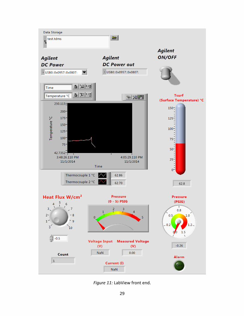
Figure 11: LabView front end.
29

Figure 12: LabViewblock diagram.
30

When CHF is detected with a sudden temperature rise, heat flux is immediately lowered
to a safe level (80% of CHF) and then gradually decreased back to 0 W/cm2. Data collected
during the tests were used to generate boiling curves, in the form of surface superheat
(∆Tsat= Tsurf- Tsat) vs. heat flux (q"), for each heater sample.
3.7 Experimental Uncertainties
Experimental uncertainties are estimated mainly for heat flux and temperature
measurements that are critical in performance evaluation. Error involved in heat flux
measurement (considering variations in voltage, current, and area) was ± 3.0%. The estimated
uncertainty in the temperature measurements was ± 0.2°C.
31

CHAPTER 4
RESULTS AND DISCUSSIONS
This chapter provides the experimental results, and discusses the findings based on
nucleate boiling performance. Test data are organized in four sections, referring to various
types of surfaces, namely, reference, hydrophobic, hydrophilic, and hydrophobic/hydrophilic
surfaces. Another section was included at the end to summarize and compare the results from
the tested surfaces. The performance of the enhanced surfaces was evaluated considering their
boiling incipience, heat transfer coefficient, and critical heat flux.
4.1 Reference Surface
Testing effort started with smooth, plain surfaces to obtain baseline data for all other
surfaces. In these tests three sets of data were taken and processed from the same heater. First
test was conducted with the heater Ref #4. The second test was done after re-polishing the
same heater’s surface, and denoted as Ref # 4 P. The third attempt simply involved retesting
the Ref # 4 P, and thus denoted as Ref # 4 P R. Results from the three tests are included in
Figure 12 in the form of boiling curve (i.e., ∆Tsat vs. q”), and they all followed a similar trend for
the entire testing range, involving natural convection, boiling incipience, nucleate boiling, and
CHF phases.
The initial natural convection mode, at heat fluxes of ≤3 W/cm2, was extended up to a
surface superheat range of 18°C to 23°C. Results from the three tests in this part were very
consistent as indicated by the overlapped data.
32

At boiling incipience, heaters experienced a temperature overshoot. The surface
superheat and the temperature overshoot at boiling incipience were recorded as 18.0oC and
2.9oC for the Ref # 4, 19.5oC and 5.1oC for the Ref # 4 R, and 23.5°C to 6.5°C for the Ref # 4 R P.
Temperature overshoot is a common phenomenon that is observed at the boiling incipience of
highly wetting liquids, such as HFE -7100 dielectric liquid. It is marked by a sudden temperature
decrease on the boiling surface upon the start of nucleation at numerous sites simultaneously.
Since highly wetting liquids tend to fill even the small surface cavities, that might contain
air/vapor and potentially serve as active nucleation sites, the boiling on such a surface requires
a larger surface superheat in order to grow and activate the smaller air/vapor pockets
remaining on the surface cavities. When the nucleation eventually starts, and as the bubbles
depart from the surface, they are replaced by fresh, colder incoming liquid, and the surface
experiences a sudden temperature drop although the heat flux remains the same. Temperature
overshoot is not a desired aspect since nucleation starts at larger surface superheats resulting
in higher device temperatures, and it is followed by a sudden temperature drop causing
thermally induced stresses on the device. Moreover, for the case of immersion cooling with
highly wetting liquids, the surface superheat and the magnitude of the following temperature
overshoot at boiling incipience a requite unpredictable.
In the nucleate boiling mode, three tests showed similar trends, but their heat transfer
performance slightly varied. The heater Ref # 4attained CHF of 19 W/cm2ata surface superheat
of 30.5°C, which represents the practical upper limit for immersion cooling with this particular
surface. The heater Ref # 4 Preached CHF at 19 W/cm2 at a surface superheat of 33°C. The
heater Ref # 4 P R had the same CHF at 19 W/cm2 at a surface superheat of 34°C.
33

Figure 13: Boiling curves of the reference surfaces.
In an effort to better represent the performance variation of the reference surface, and
simplify the comparison with other surfaces, the data from the three tests were averaged (by
calculating the arithmetic mean of surface superheats from the three tests at a given heat flux
level)to get a single baseline data, represented as the heater Ref (black solid line in Figure 13)
throughout this study.
As a common way to define the heat transfer performance, heat transfer coefficient
(HTC, or h) values are also calculated and included in Figure 14 as a function of heat flux. As can
be seen in this plot, HTCs increase as heat flux increases due to more rigorous boiling (or
34

increased frequency of nucleation), and reaches the highest value at 19 W/cm2near CHF. The
highest HTC value for the baseline data (Ref) is 6,100 W/m2oC at a heat flux of 19 W/cm2.
Figure 14: HTC of reference surfaces as a function of heat flux.
4.2 Hydrophobic Surfaces
Once the baseline data set from the reference surface (Ref) was obtained, investigation
of the hydrophobic surfaces was started. This group of heaters involved a fully hydrophobic
surface, as well as two patterned hydrophobic surfaces that feature circular patterns of 40 and
100 µm in size.
35

The data from fully hydrophobic surface, HPho#17, is plotted in Figure 15 against the
reference surface Ref. Initially, at very low heat fluxes (≤2 W/cm2), the surface HPho #17 had a
similar boiling curve, but it did not experience any temperature overshoot at the boiling
incipience at 3 W/cm2 heat flux and approximately 15oC surface superheat. The surface HPho
#17 smoothly transitioned to nucleate boiling regime and provided a higher heat transfer rate
in the low-to-mid heat flux range as indicated by a steeper curve. However, the surface HPho
#17 reached CHF at a much lower level at 14 W/cm2with a surface superheat of 22.7°C.The low
CHF from the fully hydrophobic surface can be explained by the inherent characteristic of this
coating that would considerably reduce the working fluid’s wetting ability; in other words,
facilitate the formation of vapor layer on the surface that leads to CHF.
Figure 15: Boiling curves of reference surface and fully hydrophobic surface.
36

Results from the patterned hydrophobic surfaces HPho_40 #6 and HPho_100 #7 are
shown in Figure 16. When compared to the surface Ref, nucleate boiling for HPho_40 #6
started much earlier at 2.0W/cm2and at a surface superheat of 9.5°C, with no distinct
temperature overshoot at the boiling incipience. This surface superheat level for HPho_40 #6
was around 7.5°C lower than that of the surface Ref. In addition to the early transition to
nucleate boiling, HPho_40 #6 provided a better performance, or higher HTC, throughout, as
indicated by the boiling curve shifted to left of the surface Ref. The HPho_40 #6 attained a CHF
of 22.5 W/cm2 at 27.6°C surface superheat. Therefore, patterned hydrophobic surface also
improved CHF over the surface Ref, although such improvement was not expected initially. The
other patterned hydrophobic surface, HPho_100 #7, experienced earlier nucleation compared
to HPho_40 #6, starting at 1.0 W/cm2 heat flux at surface superheat of 2.8°C with no obvious
temperature overshoot at boiling incipience. Compared to the surface Ref, the surface
superheat at boiling incipience was around 7°C lower. With the help of active nucleation at low
surface superheats, performance of HPho_100 #7 was even better than the surface HPho_40#6
throughout the nucleate boiling regime. HPho_100 #7 also attained a higher CHF of 25.5 W/cm2
at a surface superheat of 25.7°C.
37
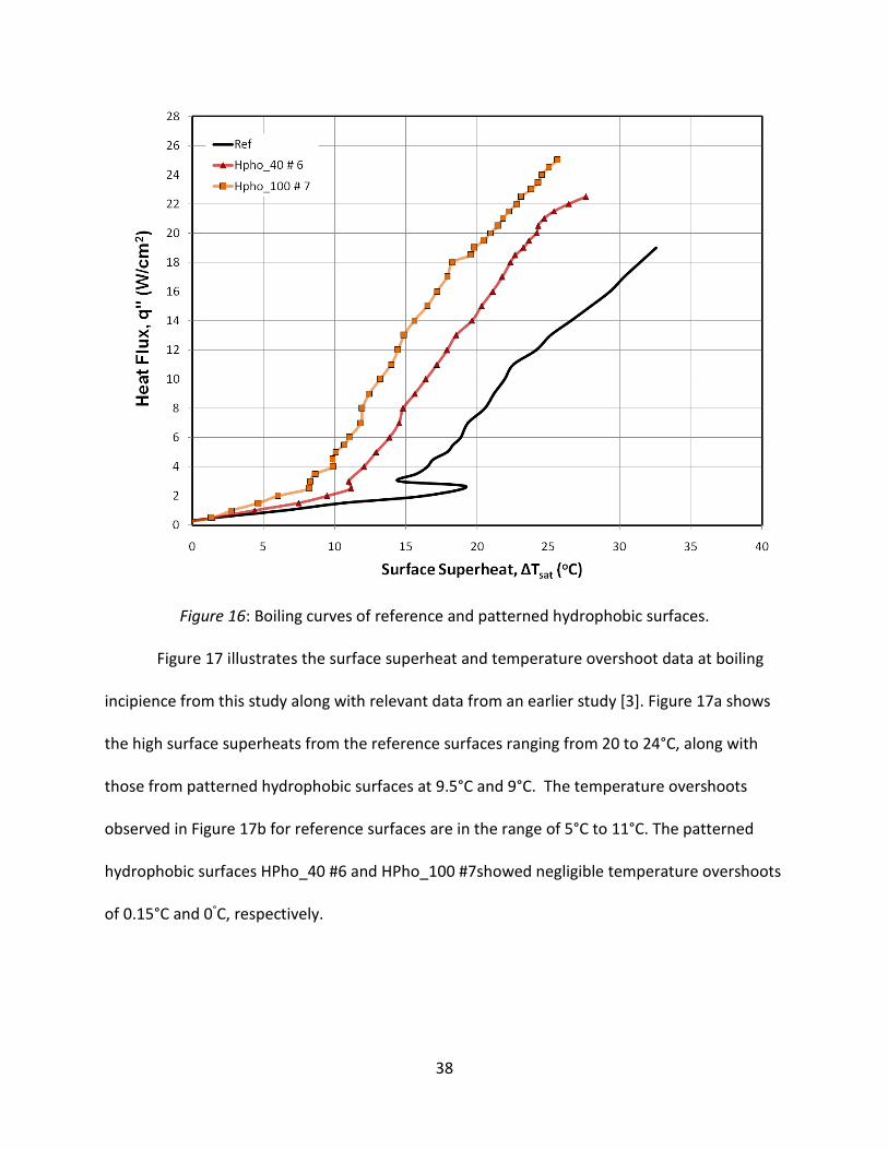
Figure 16: Boiling curves of reference and patterned hydrophobic surfaces.
Figure 17 illustrates the surface superheat and temperature overshoot data at boiling
incipience from this study along with relevant data from an earlier study [3]. Figure 17a shows
the high surface superheats from the reference surfaces ranging from 20 to 24°C, along with
those from patterned hydrophobic surfaces at 9.5°C and 9°C. The temperature overshoots
observed in Figure 17b for reference surfaces are in the range of 5°C to 11°C. The patterned
hydrophobic surfaces HPho_40 #6 and HPho_100 #7showed negligible temperature overshoots
of 0.15°C and 0°C, respectively.
38

Figure 17: Surface superheat (a) and temperature overshoot (b) at boiling incipience of reference and patterned hydrophobic surfaces
The observed performance enhancement with the surfaces HPho_40 #6 and HPho_100
#7 can be attributed to the hydrophobic patterns that promote bubble nucleation starting at
lower surface superheats. Hydrophobic patterns on a surface would help capture vapor/gas
embryos around the pattern border during the initial filling process, and therefore increase the
potential number of active nucleation sites, eventually enhancing HTC. The visual observations
with patterned hydrophobic surfaces in this study include bubbles of very similar sizes
0
5
10
15
20
25
Ref HPho_40 # 6 HPho_100 # 7
∆T s
at (o
C)
Current study
El-Genk and Bostanci [11]
0
3
6
9
12
15
Ref HPho_40 # 6 HPho_100 # 7
∆T o
ver (
o C)
39

nucleating from uniformly distributed sites, which support remarks from earlier research by
Takata et al. [19].
Figure 18 shows change of HTC as a function of heat flux for the surfaces Ref, HPho #17,
HPho_40 #6, and HPho_100 #7. Initially at low heat fluxes(<3 W/cm2), HTCs were low and
relatively steady in the single-phase natural convection dominated mode. Upon transition to
nucleate boiling mode, HTCs increased with increasing heat flux (or temperature) due to
stronger contribution of active nucleation sites. Highest HTCs (up to 9,900 W/m2oC) were
reached towards the end of fully-developed nucleate boiling regime, with corresponding
surface superheats of 22-28°C. The HTC enhancement provided by the patterned hydrophobic
surfaces over the smooth, plain surface in the mid-to-high heat flux region (>12W/cm2) were up
to 40%, and 64.3% for HPho_40 #6 and HPho_100 #7 surfaces, respectively. Moreover,
hydrophobic patterned surfaces provided higher CHF values compared to the surface Ref;
specifically 18.4% and 31.5% with HPho_40 #6 and HPho_100 #7, respectively. Previous studies
[17-18] that evaluated similar surface characteristics with water, also showed an increase in
CHF which was not necessarily expected, since a hydrophilic surface condition would mainly be
responsible for such improvement. Most likely the hydrophobic patterns control the size and
departure of the vapor bubbles and offer an extended CHF.
40

Figure 18: HTC of reference and hydrophobic surfaces as a function of heat flux.
4.3 Hydrophilic Surface
This group of heaters involved a fully hydrophilic surface, as well as three patterned
hydrophilic surfaces that feature circular patterns of 40, 100, and 250 µm in size. The data from
fully hydrophilic surface, HPho#18, is plotted in Figure 19 against the reference surface Ref.
Initially, at very low heat fluxes (≤2 W/cm2), the surface HPho #18 had a similar boiling curve,
but it did not experience any temperature overshoot at the boiling incipience at 2.5 W/cm2
heat flux and approximately 16.5oC surface superheat. The surface HPho #18 smoothly
transitioned to nucleate boiling regime and provided a higher heat transfer rate throughout this
regime as indicated by a steeper curve. Moreover, the surface HPho #18 reached CHF at a
41

higher level at 27.5 W/cm2with a surface superheat of 30°C.Thehigh CHF from the fully
hydrophilic surface can be explained by the inherent characteristic of this coating that would
considerably help the working fluid’s wetting ability by wetting the surface sufficiently and
efficiently and thus delaying the formation of vapor layer on the surface that leads to CHF.
Figure 19: Boiling curves of reference surface and fully hydrophilic surface.
Results from the patterned hydrophilicsurfacesHPhi_40 #12,HPhi_100 #13 and
HPhi_250 # 11 are shown in Figure 20. When compared to the surface Ref, nucleate boiling for
HPhi_40 #12 started much earlier at 2.0W/cm2 and at a surface superheat of 13.5°C, with no
distinct temperature overshoot at the boiling incipience. This surface superheat level for
HPhi_40 #12 was around 3.5°C lower than that of the surface Ref. In addition to the early
42

transition to nucleate boiling, HPhi_40 #12did not provide a greater performance, but it did
provide a higher HTC, throughout, as indicated by the boiling curve. The HPhi_40 #12 attained a
CHF of 26W/cm2 at 36.5°C surface superheat. Therefore, the patterned hydrophilic surface
mainly improved the CHF over the surface Ref, as expected. The other patterned hydrophilic
surface, HPhi_100 #13, experienced a later nucleation compared to HPhi_40 #12, starting at 3.0
W/cm2 heat flux at surface superheat of 14.5°C with no obvious temperature overshoot at
boiling incipience. Compared to the surface Ref, the surface superheat at boiling incipience was
around 2.5°C lower. The performance of HPhi_100 #13 was at par with the surfaceHPhi_40#12
throughout the nucleate boiling regime. HPho_100 #13 also attained a high CHF of 24W/cm2 at
a surface superheat of 35°C. The other patterned hydrophilic surface, HPhi_250 #11,
experienced an earlier nucleation compared to HPhi_100 #13, starting at 2.0 W/cm2 heat flux at
surface superheat of 13°C with no obvious temperature overshoot at boiling incipience.
Compared to the surface Ref, the surface superheat at boiling incipience was around 4°C lower.
The performance of HPhi_250 #13 overlapped the data of the surfaces HPhi_40#12 and
HPhi_100 #13 throughout the nucleate boiling regime. HPho_250 #13 also attained a high CHF
of 25W/cm2 at a surface superheat of 35.5°C.
43

Figure 20: Boiling curves of reference surface and patterned hydrophilic surfaces.
Figure21 shows change of HTC as a function of heat flux for the surfaces Ref, HPhi #18,
HPhi_40#12, HPhi_100 #13, and HPhi_250 #11. Initially at low heat fluxes(<3 W/cm2), HTCs
were low and relatively steady in the single-phase natural convection dominated mode. Upon
transition to nucleate boiling mode, HTCs increased only for the fully hydrophilic surface with
increasing heat flux (or temperature). Highest HTCs (up to 9,800 W/m2°C) were reached
towards the end of fully-developed nucleate boiling regime, with corresponding surface
superheats of 25 - 30°C for the fully hydrophilic surface. The HTC enhancement provided by the
patterned hydrophilic surfaces over the smooth, plain surface in the mid-to-high heat flux
region (>12W/cm2) were low, at 13%, 7% and 9% for HPhi_40 #12, HPhi_100 #13 and HPhi_250
44

#11 surfaces, respectively. However, hydrophilic patterned surfaces provided higher CHF values
compared to the surface Ref; specifically 36.8%, 26.3% and 31.5% with HPhi_40 #12, HPhi_100
#13 and HPhi_250 #11, respectively. Based on the previous studies [17-18] that evaluated
similar surface characteristics with water, an increase in CHF was expected, since a hydrophilic
surface condition would mainly be responsible for such improvement due to better wettability
and delayed occurrence of vapor coalescence near CHF.
Figure 21: HTC of reference and hydrophilic surfaces as a function of heat flux.
45
4.4 Hydrophobic/Hydrophilic Surface
This final group of heaters involves a combination of hydrophobic and hydrophilic
surfaces that feature circular patterns of 40and 250 µm in size.
Results from the patterned hydrophobic/hydrophilic surfaces HPho/HPhi_40 #20 and
HPho/HPhi_250 #19 are shown in Figure 22. When compared to the surface Ref, nucleate
boiling for HPho/HPhi_40 #20 started much earlier at 1.5 W/cm2and at a surface superheat of
8.5°C, with no distinct temperature overshoot at the boiling incipience. This surface superheat
level for HPho/HPhi_40 #20 was around 8.5°C lower than that of the surface Ref. In addition to
the early transition to nucleate boiling, HPho/HPhi_40 #20 provided a better performance, or
higher HTC, throughout, as indicated by the boiling curve shifted to left of the surface Ref. The
HPho/HPhi_40 #20 attained a high CHF of 28W/cm2at 33.5°Csurfacesuperheat. Therefore,
patterned hydrophobic/hydrophilic surface also improved CHF over the surface Ref, as
expected. The other patterned hydrophobic surface, HPho/HPhi_250 #19, experienced a little
delayed nucleation compared to HPho/HPhi_250 #19, starting at 2W/cm2 heat flux at surface
superheat of 8.5°C with no obvious temperature overshoot at boiling incipience. Compared to
the surface Ref, the surface superheat at boiling incipience was around 8.5°C lower. With the
help of active nucleation at low surface superheats, performance of HPho/HPhi_250 #19 was
comparable with the surface HPho/HPhi_40#20 throughout the nucleate boiling regime.
HPho/HPhi_250 #19 also attained a higher CHF of 27W/cm2 at a surface superheat of 29.5°C.
46

Figure 22: Boiling curves of reference surface and patterned hydrophobic/hydrophilic surfaces.
Figure23 shows change of HTC as a function of heat flux for the surfaces Ref,
HPho/HPhi_40 #20 and HPho/HPhi_250 #19. Initially at low heat fluxes(<3 W/cm2), HTCs were
low and relatively steady in the single-phase natural convection dominated mode. Upon
transition to nucleate boiling mode, HTCs increased with increasing heat flux (or temperature)
due to stronger contribution of active nucleation sites. Highest HTCs (up to 10,000 W/m2oC)
were reached towards the end of fully-developed nucleate boiling regime, with corresponding
surface superheats of 25-33°C. The HTC enhancement provided by the patterned
hydrophobic/hydrophilic surfaces over the smooth, plain surface in the mid-to-high heat flux
region (>12W/cm2)wereupto49%,and59% for HPho/HPhi_40 #20 and HPho/HPhi_250 #19
surfaces, respectively. Moreover, hydrophobic/hydrophilic patterned surfaces provided higher
47

CHF values compared to the surface Ref; specifically 47.3% and 42.1% with HPho/HPhi_40 #20
and HPho/HPhi_250 #19, respectively. Previous studies and earlier results that evaluated
similar surface characteristics showed an increase in CHF for a hydrophilic surface due to its
high wetting characteristic which delays the formation of the vapor layer thus delaying CHF and
that of a hydrophobic surface wherein the surface controls the size and departure of the vapor
bubbles causing an increase in HTC. Therefore both these characteristics of HTC and CHF were
achieved in the mixed pattern since they combine the benefits of hydrophobic and hydrophilic
surfaces.
Figure 23: HTC of reference and hydrophobic/hydrophilic surfaces as a function of heat flux.
48

4.5 Overall Performance Comparison
Based on the obtained results from the four types of surfaces, this section aims to
summarize the performance trends and improvement levels by comparing selected data side by
side.
Figure 24: Boiling curves of reference and enhanced surfaces as a function of heat flux.
Data in Figure 24 indicates that all the surfaces eliminate temperature overshoot
effectively as compared to reference surface Ref. The nucleate boiling for HPho_40 and
HPho/HPhi_40 surfaces start much earlier compared to the Ref and the other surfaces, at 2.0
W/cm2at surface superheats of 9.5°C and 8.7°C, respectively.
49

Figure 25: HTC of reference and enhanced surfaces as a function of heat flux.
The highest HTC enhancement is provided by the HPho_40 and HPho/HPhi_40 surfaces
as well, in low-to-mid heat flux region, reaching 40% and 49% enhancements, respectively,
compared to the surface Ref. In high heat flux region, the surface HPhi provided comparable,
even slightly better performance in terms of HTC.
The significant improvements in CHF, as the other important performance criteria, were
achieved by the surfaces HPho/HPhi_40 and HPhi, at28 W/cm2, and 27.5 W/cm2, respectively,
compared to the Ref.
In summary, this study aimed to improve nucleate boiling heat transfer performance by
(a) eliminating temperature overshoot phenomena at boiling incipience, (b) increasing HTC, and
50

(c) increasing CHF level. Figures 24-25 clearly illustrates what hydrophobic and hydrophilic
surface characteristics can provide towards these goals. Based on the obtained experimental
data we can conclude that, all three performance aspects can be achieved by utilizing a mixed
patterned hydrophobic/hydrophilic surface that promotes early nucleation, effectively
eliminates temperature overshoot at boiling incipience, and significantly increases both HTC
and CHF. Table 4 illustrates how different types of tested surfaces performed based on the
three aspects of nucleate boiling heat transfer.
Table 4
Performance Summary of Tested Surfaces
Surface Temperature overshoot
HTC Enhancement
CHF Enhancement
Reference Present - - Hydrophobic Eliminated Low Very low Patterned hydrophobic Eliminated Medium Medium Hydrophilic Eliminated Medium High Patterned hydrophilic Eliminated Medium High Hydrophobic/Hydrophilic Eliminated High High
HTC : < 6000 W/m²°C - very low; < 8000 W/m²°C - low; < 10000 W/m²°C - medium; > 10000 W/m²°C - high
CHF: < 15 W/cm² - very low; < 20 W/cm² - low; < 25 W/cm² - medium; > 25 W/cm² - high
51
CHAPTER 5
CONCLUSIONS
The last chapter presents concluding remarks, highlights important contributions, and
outlines some recommendations that can be considered for future related research.
5.1 Concluding Remarks
This study experimentally investigated the effect of hydrophobic, hydrophilic and
hydrophobic/hydrophilic patterned surfaces in saturated nucleate boiling of HFE-7100 dielectric
liquid. Based on the results obtained from a plain, smooth surface(Ref), two hydrophobic
patterned surfaces (HPho_40,HPho_100), three hydrophilic patterned surfaces (HPho_40,
HPho_100, and HPho_250), and two hydrophobic/hydrophilic surfaces (HPho/HPhi_40,
HPho/HPhi_250) the following conclusions can be drawn:
• Hydrophobic patterned surfaces would help capturing vapor/gas around the pattern
border, increase number of active nucleation sites, and promote nucleation, resulting in
(a) an early transition to nucleate boiling, and (b) effective elimination of the
temperature overshoot at boiling incipience.
• Hydrophobic patterned surfaces enhance boiling performance throughout, with
up to 64.3% higher HTC, and up to 22.5% increase in CHF over the smooth, plain surface.
• Hydrophilic patterned surfaces would help wet the surface better because of their
highly wetting characteristic and thus delay occurrence of vapor coalescence near CHF,
and hence would increase the CHF.
52

• Hydrophilic patterned surfaces do not substantially enhance HTC but increase CHF up to
36.8% over the smooth, plain surface.
• Hydrophobic/hydrophilic mixed patterned surfaces provide the optimum enhanced
surfaces since they would combine the benefits of hydrophobic and hydrophilic surfaces.
• Hydrophobic/hydrophilic mixed patterned surfaces thus achieve enhanced boiling
performance throughout, with up to 58.5% higher HTC, and up to 47.4% increase in CHF
over the smooth, plain surface.
The present study through experimental investigation emphasized that hydrophobic and
hydrophilic surface characteristics can substantially enhance the nucleate boiling heat transfer
performance of highly wetting liquids, such as the dielectric liquid HFE-7100, as well.
5.2 Recommendations for Future Research
Based on the experience obtained from this study, the following recommendations can
be made for future nucleate boiling studies that might consider to further evaluate the effect of
hydrophobic and hydrophilic surface characteristics on performance.
• The current study should be proceeded by identifying the effect of pattern size, as well
as the percentage coverage area of the hydrophobic and hydrophilic surfaces on the
nucleate boiling performance through additional experimental data and theoretical
analysis.
• Additional testing with hydrophobic and hydrophilic surfaces to evaluate their
consistency and durability would be an important step for their implementation in
practical applications.
53

• Investigation of the similar surfaces with alternative working fluids such as water and
ethanol would provide useful database to better understand and predict the heat
transfer enhancement.
54

REFERENCES
[1] http://www.bjorn3d.com/2013/06/amd-richland-june-5-2013-1201am-edt-nda/ as viewed
on 24th Oct 2014.
[2] http://bonnerandpartners.com/can-this-49-year-old-law-lead-to-rapid-profits/ as viewed
on 24th Oct 2014.
[3] http://www.reo-usa.com/docs/innovation/REO-Water-Cooled-Components.pdf as viewed
on 24th Oct 2014.
[4] El-Genk,M.S. and Bostanci, H. (2003) Saturation boiling of HFE-7100 from a copper surface,
simulating a microelectronic chip. International Journal of Heat and Mass Transfer, 46, pp.
1841-1854.
[5] Carey, V.P. (2008) Liquid-Vapor Phase-Change Phenomena 2ndEdition, Taylor and Francis,
New York, NY.
[6] Dhir, V.K.(1998) Boiling Heat Transfer. Annual Review Inc, Fluid Mech, 30:365-401
[7] Vemuri, S. Kwang J.K. (2005) Pool boiling of saturated FC-72 on nano porous surface.
International Communications in Heat and Mass Transfer, 32, 27 – 31
[8] Parker, J.K. and El-Genk, M.S. (2005) Enhanced saturation and sub cooled boiling of FC–72
dielectric liquid. International Journal of Heat and Mass Transfer, 48, 3736-3752
55
[9] Chang, J.Y.,You, S.M. (1997) Boiling heat transfer phenomena from micro porous and
porous surfaces in saturated FC – 72. International Journal Heat Mass Transfer, 40:18, 4437-
4447.
[10] El-Genk, M.S.,Ali, A.(2010) Enhanced nucleate boiling on copper micro-porous surfaces.
International Journal of Multiphase Flow, 36, 780-792.
[11] El-Genk, M.S.,Parker, J.L.(2005) Enhanced boiling of HFE-7100 dielectric liquid on porous
graphite. Energy Conversion and Management, 46, 2455-2481.
[12] Lienhard, J.H. IV., Lienhard, J.H. V. (2012) A Heat Transfer Textbook, 4th edition, Phlogiston
Press Cambridge, Massachusetts, U.S.A (http://web.mit.edu/lienhard/www/ahtt.html)
[13] El-Genk, M.S., Parker, K.L. (2008) Nucleate boiling of FC-72 and HFE-7100 on porous
graphite at different orientations and liquid sub cooling. Energy Conversion and Management,
49, 733-750.
[14] Priarone, A.(2005) Effect of surface orientation on nucleate boiling and critical heat flux of
dielectric fluid. International Journal of Thermal Sciences, 44, 822-831.
[15] Phan, H.T., Caney, N.,Marty, P.,Colasson, S.,Gavillet, J. (2009) How does surface wettability
influence nucleate boiling. Science Direct C.R. Mecanique, 337, 251 - 259.
[16] Phan, H.T., Caney, N., Marty, P., Colasson, S., Gavillet, J. (2009) Surface wettability control
by nano coating: The effects on pool boiling heat transfer and nucleation mechanism.
International Journal of Heat and Mass Transfer, 52 5459 - 5471.
56

[17] Forrest, E.,Williamson, E.,Buongiorno, J.,Hu, L.W.,Rubner, M.(2010) Augmentation of
nucleate boiling heat transfer and critical heat flux using nano particle thin-film coatings.
International Journal of Heat and Mass Transfer, 53, 58 - 67.
[18] Betz, A.R., Xu, J., Qiu, H., Attinger D. (2010) Do surfaces with mixed hydrophilic and
hydrophobic areas enhance pool boiling. Applied Physics Letters,97141909.
[19]Takata, Y.,HidakaS., Kohno, M. (2012) Effect of surface wet ability on pool boiling
enhancement by hydrophobic coating. International Journal of Air-
ConditioningandRefrigeration,20 (1)1150003-1.
[20] Wu, W., Bostanci, H., Chow, L.C., Hong, Y., Su, M.,Kizito, J.P.(2010) Nucleate boiling heat
transfer enhancement for water and FC - 72 on titanium oxide and silicon oxide surfaces.
International Journal of Heat and Mass Transfer, 53, 1773 - 1777.
[21] McDonald, B.T., Cui, T.(2011) Superhydrophilic surface modification of copper surfaces by
Layer-by-Layer self assembly and Liquid Phase Deposition of TiO2 thin film. Journal of Colloid
and Interface Science, 354, 1 - 6.
57