dionex ase 350 accelerated solvent extractor operator's manual · the thermo scientific...
TRANSCRIPT
Dionex ASE 350 Accelerated Solvent Extractor Operator's Manual
Document No. 065220Revision 04
December 2011
© 2011 by Thermo Fisher Scientific Inc. All rights reserved.
Dionex ASE 350 and Chromeleon are registered trademarks of Thermo Fisher Scientific Inc. in the United States.
Microsoft, Windows, and Windows Vista are registered trademarks of Microsoft Corporation in the United States and other countries. Adobe, Acrobat, and Adobe Reader are registered trademarks of Adobe Systems, Incorporated in the United States and other countries.
The following are registered trademarks in the United States and possibly other countries: Hastelloy is a registered trademark of Haynes International, Inc. Perlast is a registered trademark of Precision Polymer Engineering, Ltd. Viton is a registered trademark of E. I. duPont de Nemours & Company.
PEEK is a trademark of Victrex PLC.
All other trademarks are the property of Thermo Fisher Scientific and its subsidiaries.
Thermo Fisher Scientific Inc. provides this document to its customers with a product purchase to use in the product operation. This document is copyright protected and any reproduction of the whole or any part of this document is strictly prohibited, except with the written authorization of Thermo Fisher Scientific Inc.
The contents of this document are subject to change without notice. All technical information in this document is for reference purposes only. System configurations and specifications in this document supersede all previous information received by the purchaser.
Thermo Fisher Scientific Inc. makes no representations that this document is complete, accurate or error-free and assumes no responsibility and will not be liable for any errors, omissions, damage or loss that might result from any use of this document, even if the information in the document is followed properly.
This document is not part of any sales contract between Thermo Fisher Scientific Inc. and a purchaser. This document shall in no way govern or modify any Terms and Conditions of Sale, which Terms and Conditions of Sale shall govern all conflicting information between the two documents.
Revision history: Revision 01 released April 2008Revision 02 released September 2008Revision 03 released April 2011Revision 04 released December 2011
For Research Use Only. Not for use in diagnostic procedures.

Doc. 065220-04 12/11 i
Contents
1 • Introduction
1.1 Overview . . . . . . . . . . . . . . . . . . . . . . . . . . . . . . . . . . . . . . . . . . . . . . . . . 1
1.2 About This Manual . . . . . . . . . . . . . . . . . . . . . . . . . . . . . . . . . . . . . . . . . 2
1.2.1 Overview . . . . . . . . . . . . . . . . . . . . . . . . . . . . . . . . . . . . . . . . . . 2
1.2.2 Safety Messages and Notes . . . . . . . . . . . . . . . . . . . . . . . . . . . . 4
1.3 Safety and Regulatory Information . . . . . . . . . . . . . . . . . . . . . . . . . . . . . 5
1.4 Safety Labels . . . . . . . . . . . . . . . . . . . . . . . . . . . . . . . . . . . . . . . . . . . . . . 5
2 • Description
2.1 Operating Features . . . . . . . . . . . . . . . . . . . . . . . . . . . . . . . . . . . . . . . . . . 7
2.1.1 Control Panel Display . . . . . . . . . . . . . . . . . . . . . . . . . . . . . . . 10
2.1.2 Control Panel Keypad . . . . . . . . . . . . . . . . . . . . . . . . . . . . . . . 12
2.1.3 Sample Cells, Rinse Tubes, and Cell Tray . . . . . . . . . . . . . . . . 14
2.1.4 Collection Vessels, Rinse Bottles, and Collection Tray . . . . . . 16
2.1.5 Solvent Reservoir Tray . . . . . . . . . . . . . . . . . . . . . . . . . . . . . . . 19
2.1.6 Waste Bottle . . . . . . . . . . . . . . . . . . . . . . . . . . . . . . . . . . . . . . . 19
2.1.7 Heat Exchanger (Optional) . . . . . . . . . . . . . . . . . . . . . . . . . . . . 19
2.1.8 Service Area . . . . . . . . . . . . . . . . . . . . . . . . . . . . . . . . . . . . . . . 20
2.2 Right-Side Panel . . . . . . . . . . . . . . . . . . . . . . . . . . . . . . . . . . . . . . . . . . 21
2.3 Rear Panel . . . . . . . . . . . . . . . . . . . . . . . . . . . . . . . . . . . . . . . . . . . . . . . 22
Dionex ASE 350 Solvent Extraction System
ii Doc. 065220-04 12/11
2.4 Dionex ASE 350 Control . . . . . . . . . . . . . . . . . . . . . . . . . . . . . . . . . . . .23
2.4.1 Local Control . . . . . . . . . . . . . . . . . . . . . . . . . . . . . . . . . . . . . . .23
2.4.2 Remote Control . . . . . . . . . . . . . . . . . . . . . . . . . . . . . . . . . . . . .24
2.5 Chromeleon Software . . . . . . . . . . . . . . . . . . . . . . . . . . . . . . . . . . . . . . .25
2.5.1 Chromeleon Quick Start . . . . . . . . . . . . . . . . . . . . . . . . . . . . . .25
2.5.2 Overview of Chromeleon Features . . . . . . . . . . . . . . . . . . . . . .28
2.5.3 System Wellness . . . . . . . . . . . . . . . . . . . . . . . . . . . . . . . . . . . .30
2.6 Extraction Process . . . . . . . . . . . . . . . . . . . . . . . . . . . . . . . . . . . . . . . . .31
2.7 Method and Sequence Control . . . . . . . . . . . . . . . . . . . . . . . . . . . . . . . .42
2.7.1 Solvent Saver Mode . . . . . . . . . . . . . . . . . . . . . . . . . . . . . . . . .43
3 • Operation and Maintenance
3.1 Preparing to Run . . . . . . . . . . . . . . . . . . . . . . . . . . . . . . . . . . . . . . . . . . .47
3.1.1 Selecting and Preparing Extraction Solvents . . . . . . . . . . . . . .47
3.1.2 Filling the Solvent Reservoir . . . . . . . . . . . . . . . . . . . . . . . . . . .51
3.1.3 Preparing the Sample . . . . . . . . . . . . . . . . . . . . . . . . . . . . . . . . .54
3.1.4 Selecting the Sample Cell . . . . . . . . . . . . . . . . . . . . . . . . . . . . .56
3.1.5 Installing the Sample Cell Filter . . . . . . . . . . . . . . . . . . . . . . . .57
3.1.6 Filling the Sample Cell . . . . . . . . . . . . . . . . . . . . . . . . . . . . . . .59
3.1.7 Loading the Cell Tray . . . . . . . . . . . . . . . . . . . . . . . . . . . . . . . .62
3.1.8 Loading Collection Vessels . . . . . . . . . . . . . . . . . . . . . . . . . . . .64
3.1.9 Rinsing/Priming the System . . . . . . . . . . . . . . . . . . . . . . . . . . .68
3.1.10 Automatic Rinsing Between Samples . . . . . . . . . . . . . . . . . . . .70
3.1.11 Selecting Local or Remote Mode . . . . . . . . . . . . . . . . . . . . . . .71
Contents
Doc. 065220-04 12/11 iii
3.2 Methods and Sequences . . . . . . . . . . . . . . . . . . . . . . . . . . . . . . . . . . . . 74
3.2.1 Creating Methods . . . . . . . . . . . . . . . . . . . . . . . . . . . . . . . . . . . 75
3.2.2 Example Methods . . . . . . . . . . . . . . . . . . . . . . . . . . . . . . . . . . . 82
3.2.3 Creating Sequences . . . . . . . . . . . . . . . . . . . . . . . . . . . . . . . . . 87
3.2.4 Example Sequences . . . . . . . . . . . . . . . . . . . . . . . . . . . . . . . . . 91
3.3 Methods and Sequences in Chromeleon . . . . . . . . . . . . . . . . . . . . . . . . 95
3.3.1 Overview . . . . . . . . . . . . . . . . . . . . . . . . . . . . . . . . . . . . . . . . . 95
3.3.2 Example Methods . . . . . . . . . . . . . . . . . . . . . . . . . . . . . . . . . . . 97
3.4 Method Development Guidelines . . . . . . . . . . . . . . . . . . . . . . . . . . . . 105
3.5 Operating the Dionex ASE 350 . . . . . . . . . . . . . . . . . . . . . . . . . . . . . . 107
3.5.1 Operating Under Method Control . . . . . . . . . . . . . . . . . . . . . 107
3.5.2 Operating Under Sequence Control . . . . . . . . . . . . . . . . . . . . 110
3.5.3 Stopping a Run . . . . . . . . . . . . . . . . . . . . . . . . . . . . . . . . . . . . 112
3.6 Performing Post-Run Procedures . . . . . . . . . . . . . . . . . . . . . . . . . . . . 113
3.6.1 Cleaning the Sample Cells . . . . . . . . . . . . . . . . . . . . . . . . . . . 113
3.6.2 Processing Extracts . . . . . . . . . . . . . . . . . . . . . . . . . . . . . . . . . 114
3.7 Performing Routine Maintenance . . . . . . . . . . . . . . . . . . . . . . . . . . . . 114
3.7.1 Daily Maintenance . . . . . . . . . . . . . . . . . . . . . . . . . . . . . . . . . 114
3.7.2 Periodic Maintenance . . . . . . . . . . . . . . . . . . . . . . . . . . . . . . . 115
3.7.3 Annual Maintenance . . . . . . . . . . . . . . . . . . . . . . . . . . . . . . . . 115
3.8 Shutting Down . . . . . . . . . . . . . . . . . . . . . . . . . . . . . . . . . . . . . . . . . . . 116
4 • Troubleshooting
4.1 Error Messages . . . . . . . . . . . . . . . . . . . . . . . . . . . . . . . . . . . . . . . . . . 117

Dionex ASE 350 Solvent Extraction System
iv Doc. 065220-04 12/11
4.2 Liquid Leaks . . . . . . . . . . . . . . . . . . . . . . . . . . . . . . . . . . . . . . . . . . . . .140
4.3 Gas/Air Leaks . . . . . . . . . . . . . . . . . . . . . . . . . . . . . . . . . . . . . . . . . . . .142
4.4 Stopped System . . . . . . . . . . . . . . . . . . . . . . . . . . . . . . . . . . . . . . . . . .142
5 • Service
5.1 Replacing Tubing and Fittings . . . . . . . . . . . . . . . . . . . . . . . . . . . . . . .145
5.2 Replacing the Cell End Cap Seal . . . . . . . . . . . . . . . . . . . . . . . . . . . . .145
5.3 Replacing the Cell End Cap O-Ring . . . . . . . . . . . . . . . . . . . . . . . . . . .149
5.4 Replacing the Pump Check Valve Cartridges . . . . . . . . . . . . . . . . . . .150
5.4.1 Before Beginning . . . . . . . . . . . . . . . . . . . . . . . . . . . . . . . . . . .150
5.4.2 Removing the Pump . . . . . . . . . . . . . . . . . . . . . . . . . . . . . . . .150
5.4.3 Removing the Check Valves and Cartridges . . . . . . . . . . . . . .151
5.4.4 Installing New Check Valve Cartridges . . . . . . . . . . . . . . . . .152
5.4.5 Reinstalling the Check Valves . . . . . . . . . . . . . . . . . . . . . . . . .152
5.4.6 Cleaning the Check Valves . . . . . . . . . . . . . . . . . . . . . . . . . . .153
5.4.7 Reinstalling the Pump . . . . . . . . . . . . . . . . . . . . . . . . . . . . . . .153
5.4.8 Completing the Procedure . . . . . . . . . . . . . . . . . . . . . . . . . . . .153
5.5 Replacing the Pump Seals . . . . . . . . . . . . . . . . . . . . . . . . . . . . . . . . . .154
5.5.1 Before Beginning . . . . . . . . . . . . . . . . . . . . . . . . . . . . . . . . . . .154
5.5.2 Removing the Pump . . . . . . . . . . . . . . . . . . . . . . . . . . . . . . . .154
5.5.3 Replacing the Piston High-Pressure Seal . . . . . . . . . . . . . . . .154
5.5.4 Replacing the Piston Air Seal . . . . . . . . . . . . . . . . . . . . . . . . .156
5.5.5 Reinstalling the Pump . . . . . . . . . . . . . . . . . . . . . . . . . . . . . . .158
5.5.6 Completing the Procedure . . . . . . . . . . . . . . . . . . . . . . . . . . . .159

Contents
Doc. 065220-04 12/11 v
5.6 Replacing the Pressure Relief Valve . . . . . . . . . . . . . . . . . . . . . . . . . . 160
5.7 Rebuilding the Static Valve . . . . . . . . . . . . . . . . . . . . . . . . . . . . . . . . . 162
5.7.1 Removing the Static Valve from the System . . . . . . . . . . . . . 164
5.7.2 Disassembling the Static Valve Body . . . . . . . . . . . . . . . . . . 168
5.7.3 Installing the New Seals . . . . . . . . . . . . . . . . . . . . . . . . . . . . . 170
5.7.4 Reassembling the Static Valve . . . . . . . . . . . . . . . . . . . . . . . . 171
5.7.5 Reinstalling the Static Valve . . . . . . . . . . . . . . . . . . . . . . . . . 175
5.8 Replacing the Source Needle . . . . . . . . . . . . . . . . . . . . . . . . . . . . . . . . 178
5.9 Replacing the Hydrocarbon Sensor . . . . . . . . . . . . . . . . . . . . . . . . . . . 182
5.10 Replacing the Main Power Fuses . . . . . . . . . . . . . . . . . . . . . . . . . . . . 184
A • Specifications
A.1 Electrical . . . . . . . . . . . . . . . . . . . . . . . . . . . . . . . . . . . . . . . . . . . . . . . 185
A.2 Environmental . . . . . . . . . . . . . . . . . . . . . . . . . . . . . . . . . . . . . . . . . . . 185
A.3 Physical . . . . . . . . . . . . . . . . . . . . . . . . . . . . . . . . . . . . . . . . . . . . . . . . 186
A.4 Pneumatic . . . . . . . . . . . . . . . . . . . . . . . . . . . . . . . . . . . . . . . . . . . . . . 186
A.5 Display and Keypad . . . . . . . . . . . . . . . . . . . . . . . . . . . . . . . . . . . . . . 186
A.6 Sample Cells and Tray . . . . . . . . . . . . . . . . . . . . . . . . . . . . . . . . . . . . . 186
A.7 Collection Vessels and Tray . . . . . . . . . . . . . . . . . . . . . . . . . . . . . . . . 187
A.8 Interior Components . . . . . . . . . . . . . . . . . . . . . . . . . . . . . . . . . . . . . . 187
B • Installation
B.1 Facility Requirements . . . . . . . . . . . . . . . . . . . . . . . . . . . . . . . . . . . . . 189
B.2 Getting Ready to Install the Dionex ASE 350 . . . . . . . . . . . . . . . . . . . 190

Dionex ASE 350 Solvent Extraction System
vi Doc. 065220-04 12/11
B.3 Connecting the Air/Nitrogen Sources . . . . . . . . . . . . . . . . . . . . . . . . . .191
B.4 Checking the Oven Voltage Switch Settings . . . . . . . . . . . . . . . . . . . .195
B.5 Connecting the USB Cable (Optional) . . . . . . . . . . . . . . . . . . . . . . . . .196
B.6 Connecting the Power Cord . . . . . . . . . . . . . . . . . . . . . . . . . . . . . . . . .197
B.7 Setting Up Chromeleon (Optional) . . . . . . . . . . . . . . . . . . . . . . . . . . . .198
B.8 Checking Pressure Readings . . . . . . . . . . . . . . . . . . . . . . . . . . . . . . . .201
B.9 Connecting the Solvent Reservoirs . . . . . . . . . . . . . . . . . . . . . . . . . . . .202
B.10 Installing the Waste Bottle . . . . . . . . . . . . . . . . . . . . . . . . . . . . . . . . . .205
B.11 Installing the Heat Exchanger (Optional) . . . . . . . . . . . . . . . . . . . . . . .205
B.12 Inspecting the Cell and Rinse Tube . . . . . . . . . . . . . . . . . . . . . . . . . . .206
B.13 Rinsing/Priming the System . . . . . . . . . . . . . . . . . . . . . . . . . . . . . . . . .207
B.14 System Setup . . . . . . . . . . . . . . . . . . . . . . . . . . . . . . . . . . . . . . . . . . . .209
C • Diagnostic Screens
C.1 Power-Up Screen . . . . . . . . . . . . . . . . . . . . . . . . . . . . . . . . . . . . . . . . .214
C.2 Sensor Status Screen . . . . . . . . . . . . . . . . . . . . . . . . . . . . . . . . . . . . . . .215
C.3 Pressure Regulators Screen . . . . . . . . . . . . . . . . . . . . . . . . . . . . . . . . .218
C.4 Usage Log Screen . . . . . . . . . . . . . . . . . . . . . . . . . . . . . . . . . . . . . . . . .220
C.5 Error Log Screen . . . . . . . . . . . . . . . . . . . . . . . . . . . . . . . . . . . . . . . . .222
C.6 Detailed Status Screen . . . . . . . . . . . . . . . . . . . . . . . . . . . . . . . . . . . . .223
C.7 Hydrocarbon Status Screen . . . . . . . . . . . . . . . . . . . . . . . . . . . . . . . . .224
D • Reordering Information

Contents
Doc. 065220-04 12/11 vii
E • Theory of ASE
E.1 Introduction . . . . . . . . . . . . . . . . . . . . . . . . . . . . . . . . . . . . . . . . . . . . . 229
E.2 Operation . . . . . . . . . . . . . . . . . . . . . . . . . . . . . . . . . . . . . . . . . . . . . . . 230
E.3 Method Optimization . . . . . . . . . . . . . . . . . . . . . . . . . . . . . . . . . . . . . . 233
E.3.1 Sample Preparation . . . . . . . . . . . . . . . . . . . . . . . . . . . . . . . . . 233
E.3.2 Extraction Parameters . . . . . . . . . . . . . . . . . . . . . . . . . . . . . . . 236
E.4 Method Development . . . . . . . . . . . . . . . . . . . . . . . . . . . . . . . . . . . . . 239
E.5 Selectivity in ASE . . . . . . . . . . . . . . . . . . . . . . . . . . . . . . . . . . . . . . . . 240
E.6 References . . . . . . . . . . . . . . . . . . . . . . . . . . . . . . . . . . . . . . . . . . . . . . 245

Dionex ASE 350 Solvent Extraction System
viii Doc. 065220-04 12/11
Doc. 065220-04 12/11 1
1 • Introduction
1.1 Overview
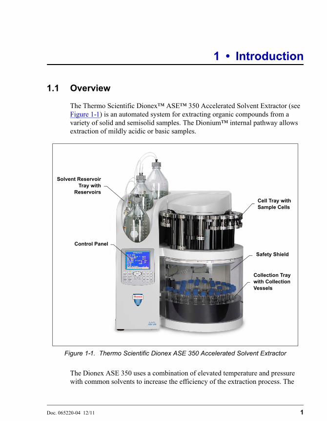
The Thermo Scientific Dionex™ ASE™ 350 Accelerated Solvent Extractor (see Figure 1-1) is an automated system for extracting organic compounds from a variety of solid and semisolid samples. The Dionium™ internal pathway allows extraction of mildly acidic or basic samples.
The Dionex ASE 350 uses a combination of elevated temperature and pressure with common solvents to increase the efficiency of the extraction process. The
Figure 1-1. Thermo Scientific Dionex ASE 350 Accelerated Solvent Extractor
Solvent ReservoirTray with
Reservoirs
Control Panel
Safety Shield
Cell Tray with Sample Cells
Collection Tray with Collection Vessels

Dionex ASE 350 Solvent Extraction System
2 Doc. 065220-04 12/11
result is faster run times and a significant reduction in solvent use. To further reduce solvent use, the Dionex ASE 350 supports a unique extraction method called the solvent saver mode; for details, see Section 2.7.1.
During a run, the cell is filled with solvent and then heated and pressurized to maintain the solvent in a liquid state. After the run, the extract is rinsed from the cell into a collection vessel (a bottle or vial). If adsorbents are used in the sample cell, post-extraction cleanup may not be required. If adsorbents are not used, sample cleanup may be required.
Control Options
The Dionex ASE 350 can be controlled locally, from the front panel keypad and display, or remotely, with a personal computer running Microsoft® Windows Vista® or Windows XP operating system and Thermo Scientific Dionex Chromeleon® 7 Chromatography Data System (release 7.1 or later).
With Chromeleon, you can create and run methods and sequences that use not only the extraction modes available from the Dionex ASE 350 front panel, but two additional modes (fixed volume and gradient) that are available only in Chromeleon (for details, see Section 2.7.1).
For communication between the Dionex ASE 350 and Chromeleon, the Dionex ASE 350 is connected to a USB (Universal Serial Bus) port on the Chromeleon PC. Up to four Dionex ASE 350 systems can be automated by one Chromeleon workstation.
1.2 About This Manual
1.2.1 Overview
The electronic version (i.e., PDF file) of the Dionex ASE 350 operator’s manual contains numerous links that you can click to go to other locations within the manual. These links include:
• Table of contents entries
• Index entries
• Cross-references (underlined in blue) to sections, figures, tables, etc.
If you are not familiar with how to navigate PDF files, refer to the Help system for Adobe® Acrobat® or Adobe Reader® for assistance.

1 • Introduction
Doc. 065220-04 12/11 3
NOTE For detailed information about using Chromeleon tooperate the Dionex ASE 350, refer to the ChromeleonHelp or to the software manuals provided on theThermo Scientific Reference Library DVD(P/N 053891).
Chapter 1 Introduction
Introduces the Dionex ASE 350 system; explains the conventions used in this manual, including safety-related information.
Chapter 2 Description
Describes Dionex ASE 350 operating features and the extraction process.
Chapter 3Operation and
Maintenance
Provides operating instructions and routine preventive maintenance requirements.
Chapter 4Troubleshooting
Lists error messages and explains how to troubleshoot them; lists operating problems and how to resolve them.
Chapter 5Service
Provides step-by-step instructions for routine service and parts replacement procedures that the user can perform.
Appendix ASpecifications
Provides specifications and installation site requirements.
Appendix BInstallation
Explains how to install the Dionex ASE 350.
Appendix CDiagnostic
Screens
Illustrates and describes the Dionex ASE 350 front panel diagnostic screens.
Appendix DReordering
Information
Lists spare parts for the Dionex ASE 350.
Appendix ETheory of ASE
Describes the theory behind the ASE (accelerated solvent extraction) technique.

Dionex ASE 350 Solvent Extraction System
4 Doc. 065220-04 12/11
1.2.2 Safety Messages and Notes
This manual contains warnings and precautionary statements that, when properly followed, can prevent personal injury to the operator and/or damage to the Dionex ASE 350. Safety messages appear in bold type and are accompanied by icons, as shown here.
Messages d’avertissement en français
Warnhinweise in Deutsch
Indicates an imminently hazardous situation which, if not avoided, willresult in death or serious injury.
Indicates a potentially hazardous situation which, if not avoided, mayresult in death or serious injury.
Indicates a potentially hazardous situation which, if not avoided, mayresult in minor or moderate injury.
Indicates that the function or process of the instrument may beimpaired. Operation does not constitute a hazard.
Signale une situation de danger immédiat qui, si elle n'est pas évitée,entraînera des blessures graves à mortelles.
Signale une situation de danger potentiel qui, si elle n'est pas évitée,pourrait entraîner des blessures graves à mortelles.
Signale une situation de danger potentiel qui, si elle n'est pas évitée,pourrait entraîner des blessures mineures à modérées. Égalementutilisé pour signaler une situation ou une pratique qui pourraitgravement endommager l'instrument mais qui n'entraînera pas deblessures.
Bedeutet unmittelbare Gefahr. Mißachtung kann zum Tod oderschwerwiegenden Verletzungen führen.
1 • Introduction
Doc. 065220-04 12/11 5
Informational messages also appear throughout this manual. These are labeled NOTE and are in bold type.
NOTE NOTES call attention to certain information. Theyalert the user to an unexpected result of an action,suggest how to optimize instrument performance,etc.
1.3 Safety and Regulatory Information
The Dionex ASE 350 was manufactured by Thermo Fisher Scientific Inc. at the following location: 527 Lakeside Drive, Sunnyvale, CA 94088-3603 U.S.A. The Dionex ASE 350 is designed for solvent extraction applications and should not be used for any other purpose. Operation of a Dionex ASE 350 in a manner not specified by Thermo Fisher Scientific may result in personal injury.
If there is a question regarding appropriate usage, contact Technical Support for Dionex products. In the U.S. and Canada, call 1-800-346-6390. Outside the U.S. and Canada, call the nearest Thermo Fisher Scientific office.
1.4 Safety Labels
The cTUVus Mark safety label and the CE Mark label on the Dionex ASE 350 indicate that the Dionex ASE 350 is in compliance with the following standards.
EMC Susceptibility and Immunity
• EN 61326-1:2006
Safety
• CAN/CSA-C22.2 No. 61010-1:2004
• EN 61010-1:2001
Bedeutet eine mögliche Gefährdung. Mißachtung kann zum Tod oderschwerwiegenden Verletzungen führen.
Bedeutet eine mögliche Gefährdung. Mißachtung kann zu kleinerenoder mittelschweren Verletzungen führen. Wird auch verwendet, wenneine Situation zu schweren Schäden am Gerät führen kann, jedochkeine Verletzungsgefahr besteht.

Dionex ASE 350 Solvent Extraction System
6 Doc. 065220-04 12/11
• UL 3101-1/10.93
• UL 61010-1:2004
The symbols below appear on the Dionex ASE 350 or on Dionex ASE 350 labels.
Alternating current
Primary protective conductor terminal
Secondary protective conductor terminal
Power supply is on
Power supply is off
Hot surface
Indicates a potential hazard. Refer to this operator’s manual for an explanation of the hazard and how to proceed.

Doc. 065220-04 12/11 7
2 • Description
• Section 2.1 describes the operating features and components of the Dionex ASE 350.
• Section 2.6 describes the extraction process.
• Section 2.7 describes both method and sequence control of the Dionex ASE 350.
2.1 Operating Features
Figure 2-1 illustrates some of the key operating features of the Dionex ASE 350.
Figure 2-1. Dionex ASE 350 Operating Features
Solvent ReservoirTray with
Reservoirs
Control Panel
Safety Shield
Cell Tray with Sample Cells
Collection Tray with Collection Vessels
Service Area(Not visible)

Dionex ASE 350 Solvent Extraction System
8 Doc. 065220-04 12/11
Control Panel
The control panel on the front of the Dionex ASE 350 contains a liquid crystal display (LCD) and membrane keypad (see Figure 2-2) required for local control of Dionex ASE 350 operation.
Cell Tray and Sample Cells
The cell tray, on the upper right of the Dionex ASE 350, holds up to 24 sample cells of various sizes and types. The prepared sample is loaded into these cells.
Stainless steel cells are available in the following sizes: 1 mL, 5 mL, 10 mL, 22 mL, 34 mL, 66 mL, and 100 mL. Two cell sizes (66 mL and 100 mL) are available in zirconium, also.
Collection Tray and Collection Vessels
The collection tray, on the lower right of the Dionex ASE 350, holds the collection vessels (250-mL bottles and 60-mL vials). After a run, the collection vessels contain solvent and the analytes extracted from the sample.
Static Valve
The static valve, located above the collection tray, controls the flow of solvent from the sample cell.
Safety Shield
For the protection of the user, the entire run is performed behind a safety shield. A method, sequence, or rinse cannot be started unless the safety shield is closed. Closing the shield automatically locks it; the shield remains locked until the function in progress finishes (or is aborted).
Oven Area
The oven is housed at the rear of the Dionex ASE 350. This area also houses the AutoSeal arm. The arm moves the cell into and out of the oven, and seals the cell during a run.
Needle Mechanism
When positioned above a collection vessel, the needle mechanism pierces the collection vessel septum, allowing the extract to flow from the cell into the vessel.
Solvent Reservoir Tray
The solvent reservoir tray can hold up to three 2-liter reservoirs (P/N 045901). Connectors for solvent and nitrogen gas sources are located next to each reservoir.
2 • Description
Doc. 065220-04 12/11 9
Waste Bottle
A waste bottle is installed in a holder on the inside wall, to the left of the collection tray.
Service Area
The service area on the left side of the system contains the Dionex ASE 350 pump, pressure regulators, pneumatic valves and components, and electronics.
Users occasionally need access to the service area to perform routine maintenance procedures such as replacement of pump seals and check valves. To access the service area, rotate the three quarter-turn screws along the edge of the door and swing the door open.

Dionex ASE 350 Solvent Extraction System
10 Doc. 065220-04 12/11
2.1.1 Control Panel Display
The LCD (or screen), displays Dionex ASE 350 status and operating information. Fields that are in reverse video (white letters on a blue background) can be edited. Normal video fields display information, but cannot be edited.
Screen Contrast: To adjust the screen contrast, press the Contrast and Contrast buttons on the control panel keypad.
Screen Saver Mode: If there is no input to the Dionex ASE 350 for two hours (that is, no control panel buttons are pressed during this time), the LCD backlight automatically turns off. To turn on the backlight again, press any keypad button.
When the Dionex ASE 350 power is turned on, the POWER-UP screen appears (see Figure 2-2). The screen identifies the Dionex ASE 350 serial number and the version of Dionex ASE 350 firmware currently installed.
Figure 2-2. Dionex ASE 350 Control Panel
Dionex ASE 350Power-up Initialization
Please wait for power-up completion
Firmware Version: 02.00.00Boot Block Version: 01.00.00Serial Number: 0123456789
Help prompt

2 • Description
Doc. 065220-04 12/11 11
After a few seconds, the POWER-UP screen is automatically replaced by the MAIN MENU OF SCREENS (see Figure 2-3).
The MAIN MENU OF SCREENS presents six options: five screens that control Dionex ASE 350 operation, plus a DIAGNOSTIC MENU screen. There are two ways to select a menu option:
• Press the numeric button that corresponds to the screen name.
– or –
• Press an up or down arrow button to move the cursor to the screen name, and then press the Enter button.
Figure 2-3. Main Menu of Screens
MAIN MENU OF SCREENS
3) METHOD EDITOR4) SEQUENCE EDITOR
1) LOAD METHOD/SEQUENCE
5) SYSTEM SETUP
2) SYSTEM STATUS
6) DIAGNOSTICS
Help prompt

Dionex ASE 350 Solvent Extraction System
12 Doc. 065220-04 12/11
2.1.2 Control Panel Keypad
Pressing a keypad button either directly affects Dionex ASE 350 operation or affects a screen function. Table 2-1 summarizes the button functions.
Button Function
(Free Spin)
Pressing the Trays button toggles the cell and collection trays between the engaged and free spin modes. LEDs on the button indicate the current mode. When the left LED is lighted, the collection tray and cell tray can be rotated manually. Switch to free spin during loading and unloading of collection vessels and cells.
(Engaged)
When the right LED is lighted, the tray drive mechanisms are engaged and cannot be moved manually. Toggling from free spin to engaged causes the trays to rotate to the home position. Starting a run automatically engages the trays. During a run., the Trays button is disabled.
Starts a manual rinse, which is used to prime the pump or to rinse after a solvent change, after refilling a solvent reservoir, etc. The trays rotate to the nearest rinse bottle and rinse tube. A user-specified volume of solvent is then pumped through the system and into the rinse bottle. This button functions only when the Dionex ASE 350 is idle.
Starts the currently loaded method or sequence. When a run is in progress, the LED on the right side of the button is lighted.
Interrupts the current run. The pump turns off, valves close, and all flow stops. The screen displays a list of options for selection. See Section 3.5.3 for more information.
Pressing Contrast increases the screen contrast; pressing Contrast decreases the screen contrast.
Table 2-1. Dionex ASE 350 Front Panel Button Functions
Trays
Trays
Rinse
Start
Stop
Contrast
Contrast
2 • Description
Doc. 065220-04 12/11 13
The Select buttons step through predetermined options in entry fields. To confirm the selected value, press Enter or move the cursor out of the field by pressing an arrow button. In fields with predetermined numeric choices, Select increases the value by one unit and Select decreases the value by one unit. Holding down a Select button increases (or decreases) the value continuously.
The arrow buttons move the cursor in the direction of the arrow to the next entry field, if one exists. After entering a new value in an entry field, pressing an arrow button to move the cursor to another field saves the change.
Displays a context-sensitive help screen.
Displays a list of screens that can be selected for display. There are two ways to select menu options:
• Press the numeric button that corresponds to the screen name.
– or –
• Press an up or down arrow button to move the cursor to the screen name, and then press Enter.
When an operational screen is displayed, pressing Menu returns you to the MAIN MENU OF SCREENS. When a diagnostic screen is displayed, pressing Menu returns you to the DIAGNOSTIC MENU. When the DIAGNOSTIC MENU is displayed, pressing Menu returns you to the MAIN MENU OF SCREENS.
When the cursor is in an entry field, pressing a numeric button enters the selected number into the current entry field. When a menu screen is displayed, pressing a numeric button opens the corresponding menu option.
Saves changes made in entry fields. When a menu screen is displayed, pressing Enter opens the highlighted screen.
Button Function
Table 2-1. Dionex ASE 350 Front Panel Button Functions (Continued)
Select
Select
Help
Menu
1
Enter

Dionex ASE 350 Solvent Extraction System
14 Doc. 065220-04 12/11
2.1.3 Sample Cells, Rinse Tubes, and Cell Tray
NOTE Appendix D contains part numbers for cells,collection vessels, and other accessories.
Sample Cells
Stainless steel cells are available in the following sizes: 1 mL, 5 mL, 10 mL, 22 mL, 34 mL, 66 mL, and 100 mL. Two cell sizes (66 mL and 100 mL) are available in zirconium, also.
Both stainless steel and zirconium cells are suitable for extraction with solvents. Zirconium cells can also be used for the extraction of mildly basic or acidic matrices. For details about acid and base usage with the Dionex ASE 350, see “Guidelines for Selecting and Preparing Solvents” on page 48.
Sample cells consist of a cell body and two interchangeable caps, which are screwed onto each end of the cell body. The cell body and end caps are made of the same material. Inside each end cap is a frit in the same
material as the cell, as well as a PEEK™ (polyaryletherketone) seal. During a run, the cell end caps are compressed to form a tight seal between the end caps and the cell body.
Each cell end cap contains an external O-ring. The standard O-rings are made of PTFE (polytetrafluoroethylene) (P/N 049457, pkg. of 50). Viton™ O-rings (P/N 056325, pkg. of 50) are available for dioxins and other high temperature applications.
Always tighten the cell end caps by hand. Use of a wrench or othertool can damage the cell, as well as the seals inside the end caps, andwill void the product warranty.
If the external O-ring is Viton, do not use acetone or other ketones.
2 • Description
Doc. 065220-04 12/11 15
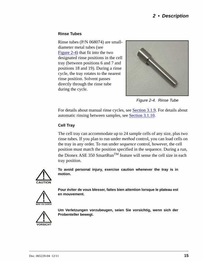
Rinse Tubes
Rinse tubes (P/N 068074) are small-diameter metal tubes (see Figure 2-4) that fit into the two designated rinse positions in the cell tray (between positions 6 and 7 and positions 18 and 19). During a rinse cycle, the tray rotates to the nearest rinse position. Solvent passes directly through the rinse tube during the cycle.
Figure 2-4. Rinse Tube
For details about manual rinse cycles, see Section 3.1.9. For details about automatic rinsing between samples, see Section 3.1.10.
Cell Tray
The cell tray can accommodate up to 24 sample cells of any size, plus two rinse tubes. If you plan to run under method control, you can load cells on the tray in any order. To run under sequence control, however, the cell position must match the position specified in the sequence. During a run, the Dionex ASE 350 SmartRunTM feature will sense the cell size in each tray position.
To avoid personal injury, exercise caution whenever the tray is inmotion.
Pour éviter de vous blesser, faites bien attention lorsque le plateau esten mouvement.
Um Verletzungen vorzubeugen, seien Sie vorsichtig, wenn sich derProbenteller bewegt.

Dionex ASE 350 Solvent Extraction System
16 Doc. 065220-04 12/11
2.1.4 Collection Vessels, Rinse Bottles, and Collection Tray
NOTE Appendix D contains part numbers for cells,collection vessels, and other accessories.
Collection Vessels
Two types of collection vessels can be installed in the Dionex ASE 350: bottles and vials. Both bottles and vials have a cap that contains a solvent-resistant septum. During a run, the needle mechanism pierces the septum, creating a liquid flow path from the sample cell to the collection vessel.
For light-sensitive samples, Thermo Fisher Scientific recommends amber vials.
The following collection vessels are available:
Collection Vessel Part Number Quantity
Clear vials, 60 mL 048784 Pkg. of 72
Amber vials, 60 mL 048781 Pkg of 72
Clear bottles, 250 mL 056284 Pkg. of 12
Before each run, carefully inspect all collection vessels for chips,scratches, or cracks. If a collection vessel shows any sign of damage,do not use it. Use each collection vessel once only.
La présence de fêlure ou d’égratignures sur les flacons de collectedoit être vérifiée avant chaque extraction. N’utilisez jamais un flaconendommagé. Les flacons sont à usage unique.
Untersuchen Sie vor jedem Lauf alle Sammelgefäße aufAbplatzungen, Kratzer oder Risse. Wenn ein Sammelgefäß eineBeschädigung aufweist, sollten Sie es nicht mehr verwenden.Verwenden Sie nicht graduierte Sammelgefäß nur ein Mal.
Use each collection vessel cap and septum once only. This preventssolvent leaks caused by piercing the septum in the cap multiple times.

2 • Description
Doc. 065220-04 12/11 17
Rinse Bottles
The rinse positions (labeled R1 and R2) each accommodate one collection bottle. Before the start of the rinse cycle, the cell tray rotates to the nearest rinse position and the bottle sensors check that the rinse bottle is present and is not full. Solvent is then pumped through the system and collected in the rinse bottle.
If a bottle sensor detects that the first rinse bottle is either full or missing, it will check the status of the next rinse bottle. If the sensors determine that both rinse bottles are absent or full, an error message is displayed on the control panel screen.
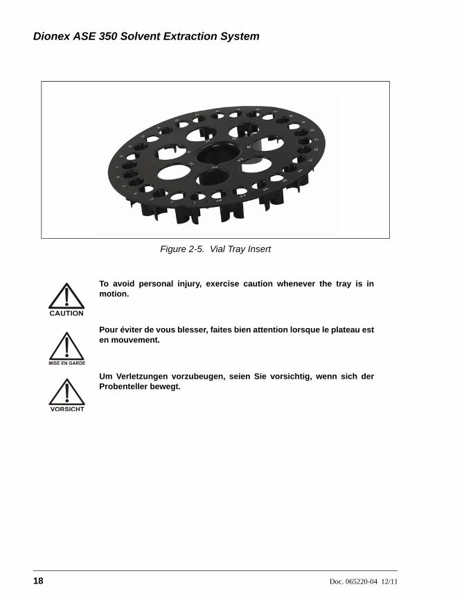
Collection Tray and Vial Tray Insert
The collection tray capacity varies, depending on whether a vial tray insert (P/N 066176) is installed. By itself, the collection tray can hold up to 14 collection bottles on the outside row, plus five collection bottles and two rinse bottles on the inside row.
The vial tray insert (see Figure 2-5) is required to accommodate collection vials. The vial tray insert resizes the holes in the collection tray to ensure that the vials, which are smaller than the collection bottles, are secured in place.
When the vial tray insert is in place, the collection tray can hold up to 28 60-mL collection vials on the outside row, plus five 250-mL collection bottles and two rinse bottles on the inside row.
The vial tray insert is provided in both the Small Volume Startup Kit (P/N 068254) and the 34-mL Volume Startup Kit (P/N 068255).
Dionex ASE 350 Solvent Extraction System
18 Doc. 065220-04 12/11
Figure 2-5. Vial Tray Insert
To avoid personal injury, exercise caution whenever the tray is inmotion.
Pour éviter de vous blesser, faites bien attention lorsque le plateau esten mouvement.
Um Verletzungen vorzubeugen, seien Sie vorsichtig, wenn sich derProbenteller bewegt.

2 • Description
Doc. 065220-04 12/11 19
2.1.5 Solvent Reservoir Tray
The Dionex ASE 350 Ship Kit (P/N 066060) includes one 2-liter glass reservoir with shatterproof plastic coating (P/N 045901) and one bottle cap assembly (P/N 068077) with tubing and fittings for connecting the reservoir to the Dionex ASE 350.
Up to two additional solvent reservoirs can be installed. When more than one reservoir is installed, the Dionex ASE 350 can do the following:
• Change solvents between runs, so that the same sample is extracted with a different solvent or so that each remaining sample is extracted with a solvent other than the one used for the previous sample.
• Select from up to three different solvent reservoirs for extractions.
• Mix two or three solvents, at the user-selected ratio, during the run.
2.1.6 Waste Bottle
A 250-mL collection bottle is used to collect waste. The waste bottle sits in a holder located to the left of the collection tray. Three vent lines, one from the pressure relief valve and two from the needle mechanism, are connected to the top of the waste bottle holder. The waste bottle collects the small amounts of solvent vented through the three lines.
A vent outlet line is also connected to the waste bottle holder. Gas is vented out this line to the rear panel, which can be connected to a fume hood. The Dionex ASE 350 Ship Kit (P/N 066060) includes 3.05 meters (10 ft) of external vent tubing (P/N 053514) for this purpose.
Check the waste bottle daily and empty it whenever necessary.
2.1.7 Heat Exchanger (Optional)
A heat exchanger (P/N 068247) is required for applications that use volatile solvents at temperatures above 175 °C. The purpose of the heat exchanger is to cool the solvent as it leaves the cell, before it enters the static valve and is delivered to the collection vessel. Use of a heat exchanger minimizes the loss of solvent and analytes during collection. The heat exchanger must be installed by Thermo Fisher Scientific personnel.

Dionex ASE 350 Solvent Extraction System
20 Doc. 065220-04 12/11
2.1.8 Service Area
The service area on the left side of the Dionex ASE 350 (see Figure 2-1) houses the pump, pressure regulators, pneumatic valves and components, and electronics.
Users occasionally need access to the service area to perform routine maintenance procedures such as replacement of pump seals and check valves. To access the service area, rotate the three quarter-turn screws along the edge of the door and swing the door open.
Always close the door to the service area before starting a run. If thedoor is open during operation, the oven may not reach and maintainthe set temperature.
Do not adjust the pressure regulators inside the service area. If youthink the regulators require adjustment, contact Thermo FisherScientific for assistance.
Do not remove any of the electronics boards from the service area.There are no user-serviceable components on the boards. If servicingis required, it must be performed by qualified personnel andappropriate electrostatic discharge (ESD) handling procedures mustbe followed.
Ne retirez aucune des cartes électroniques. Aucun des composantssur les cartes ne peut être réparé par l'utilisateur. Toute réparation doitêtre effectuée par un personnel qualifié utilisant des procédurescorrectes de décharge électrostatique.
Halten Sie sich von der Elektronik des Dionex ASE 350 fern. DieElektronik kann nicht vom Anwender gewartet werden. Falls einService erforderlich ist, ist dieser von qualifiziertem Personaldurchzuführen. Dabei müssen die geeigneten Verfahren zurelektrostatischen Entladung (ESD) eingehalten werden.

2 • Description
Doc. 065220-04 12/11 21
2.2 Right-Side Panel
Figure 2-6 illustrates the Dionex ASE 350 right-side panel.
• The POWER switch provides on/off control of the main power for the system. The power receptacle also includes a fuse drawer containing two IEC127 fast-blow fuses (P/N 954746) rated at 10 amps. For instructions on how to replace the fuses, see Section 5.10.
• The two oven voltage switches must be set to match the voltage from the power source at the Dionex ASE 350 installation site. The top switch controls the voltage for the top plate heater; the bottom switch controls the oven heater voltage. For instructions on how to set the switches, see Section B.4.
NOTE The top plate and oven heaters are automatically turnedoff after four hours of system inactivity (that is, if nocontrol panel buttons are pressed and no methods orsequences run during a four-hour period).
• The model data label lists fuse and power information, as well as the Dionex ASE 350 serial number. You will be asked to provide the serial number when ordering replacement parts for the Dionex ASE 350.
Figure 2-6. Dionex ASE 350 Right-Side Panel
Model Data Label
Power Receptacle and Fuse Drawer
Oven Voltage Switches
Dionex ASE 350 Solvent Extraction System
22 Doc. 065220-04 12/11
2.3 Rear Panel
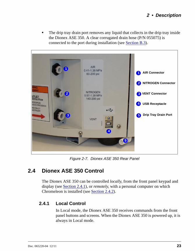
Figure 2-7 illustrates the lower right corner of the Dionex ASE 350 rear panel.
• The AIR connector provides a connection to a source of compressed air regulated to between 0.41 and 1.38 MPa (60 to 200 psi). For installation instructions, see Section B.3.
• The NITROGEN connector provides a connection to a nitrogen gas supply regulated to between 0.97 and 1.38 MPa (140 to 200 psi). For installation instructions, see Section B.3.
• The VENT connector provides a connection for the vent outlet line. For installation instructions, see Section B.3.
• The USB receptacle provides a connection to the computer on which Chromeleon software is installed. Connect a USB cable (P/N 960777) between this receptacle and a USB port on the Chromeleon computer. See Section B.5 for USB connection instructions.
Firmware Upgrades
If Chromeleon is installed, use the Chromeleon Instrument Configuration program to download new firmware versions to the Dionex ASE 350.
If you do not have access to Chromeleon, the USB receptacle on the Dionex ASE 350 rear panel can be connected to any available computer to download new firmware to the Dionex ASE 350. Installation instructions are provided with the firmware upgrade.
Do not obstruct or pressurize the vent outlet.
Ne bouchez ni ne mettez sous pression la sortie d'aération.
Halten Sie den Lüftungsauslaß frei, setzen Sie ihn nicht unter Druck.
2 • Description
Doc. 065220-04 12/11 23
• The drip tray drain port removes any liquid that collects in the drip tray inside the Dionex ASE 350. A clear corrugated drain hose (P/N 055075) is connected to the port during installation (see Section B.3).
2.4 Dionex ASE 350 Control
The Dionex ASE 350 can be controlled locally, from the front panel keypad and display (see Section 2.4.1), or remotely, with a personal computer on which Chromeleon is installed (see Section 2.4.2).
2.4.1 Local Control
In Local mode, the Dionex ASE 350 receives commands from the front panel buttons and screens. When the Dionex ASE 350 is powered up, it is always in Local mode.
Figure 2-7. Dionex ASE 350 Rear Panel
AIR Connector
USB Receptacle
VENT Connector
NITROGEN Connector2
5
3
11
2
3
4
5
4
Drip Tray Drain Port

Dionex ASE 350 Solvent Extraction System
24 Doc. 065220-04 12/11
Note that the fixed volume and gradient extraction modes (see Section 2.7.1) are not available in Local mode. Access to these options requires Chromeleon software.
2.4.2 Remote Control
In Remote mode, Chromeleon software sends commands from the host computer to the Dionex ASE 350 via the USB interface. Connecting the Dionex ASE 350 to an ePanel in Chromeleon (see Figure 2-8) immediately selects Remote mode. (An ePanel is the window where you monitor and control Dionex ASE 350 operation. ePanels are displayed on the Console in the Instruments view.)
In Remote mode, most front panel functions are disabled in order to prevent any inadvertent changes to operating parameters. However, you
Figure 2-8. Example Chromeleon Dionex ASE 350 ePanel

2 • Description
Doc. 065220-04 12/11 25
can still navigate the front panel screens, clear errors on the ERROR LOG screen (see Section C.5), and use the following buttons:
• Trays (manually rotates the collection tray and cell tray to enable loading and unloading of collection vessels and cells)
• Stop (stops the current run)
• Contrast and Contrast (adjusts the screen contrast)
To return the Dionex ASE 350 to Local mode:
• Click the Connected button on the ePanel. This disconnects the system from Chromeleon (and changes the button label to Disconnected).
– or –
• Turn off the Dionex ASE 350 power briefly.
2.5 Chromeleon Software
The Dionex ASE 350 can be controlled by a PC running Chromeleon 7 Chromatography Data System (release 7.1 or later). Chromeleon support requires Dionex ASE 350 firmware version 2.00.00 (or later).
For details about the software, refer to the Chromeleon Help or to the software manuals provided on the Thermo Scientific Reference Library DVD (P/N 053891)
2.5.1 Chromeleon Quick Start
Configuring the Dionex ASE 350
1. Open the Chromeleon Services Manager and click Start Instrument Controller.
2. Open the Instrument Configuration Manager. Click the Connect toolbar button to connect to Chromeleon.
3. To create a new instrument, click the Add Instrument toolbar button.
4. Enter a name for the new instrument.
5. Click the instrument, and then click the Add Module toolbar button.

Dionex ASE 350 Solvent Extraction System
26 Doc. 065220-04 12/11
6. In the Add module to instrument dialog box, in the Manufacturers list under Dionex, select Extraction Modules. In the Modules list, select ASE 350 Accelerated Solvent Extractor. Click OK. The Properties dialog box will appear.
7. On the General tab page, specify the following options:
• Device Name: The name used to identify the Dionex ASE 350 in Chromeleon.
• Mode: Select Live mode when configuring a Dionex ASE 350 that is physically connected to the Instrument Controller PC. The Dionex ASE 350 must be running firmware version 2.00.00 (or later). If a firmware update is required, select the serial number of the Dionex ASE 350 being connected in the Module Serial No. list, click the Download button, and select the appropriate firmware file.
Select Simulation mode only if you are configuring the Dionex ASE 350 in order to demonstrate the software.
8. On the Options tab page, specify the following options:
• Select the pressure units to be displayed in Chromeleon (psi, MPa, bar, or atm).
• If the vial tray insert is installed in the collection tray, select the Vial Tray Insert check box.
• Enter names for the solvents in positions A, B, and C of the reservoir tray.
Using Chromeleon to Control the Dionex ASE 350
When you start Chromeleon, the Chromeleon Console appears. The Console displays an ePanel with a graphic of the Dionex ASE 350, along with an overview of the system status.
Use the Manual Rinse controls below the status display to specify the rinse volume, number of rinse cycles, and solvent ratio for a manual rinse. To start the rinse, click the Rinse button.

2 • Description
Doc. 065220-04 12/11 27
Creating Instrument Methods
1. In the Chromeleon Console, on the Create menu, click Instrument Method to open the Instrument Method Wizard.
2. Use the wizard to program the following method options:
• Rinse Settings page—Specify the volume and solvent ratio to be used during a rinse. The rinse will occur in between extraction cells on a rinse tube to rinse the solvent lines after each extraction.
• Extraction Method page—Specify the extraction conditions for the extraction cell.
• Completion page—Add a comment (optional) and click the Finish button. This opens the method in the Instrument Method Editor.
3. Review the settings for Comment, Name, Description, and Run Time; make any changes required.
NOTE The Run Time setting must remain at0.000 minutes.
4. Save the method before exiting the Instrument Method Editor.
Creating Sequences
1. In the Chromeleon Console, on the Create menu, click Sequence to open the New Sequence Wizard.
2. Select the Dionex ASE 350 for which the sequence is being created.
3. Use the wizard to program the following sequence options:
• Unknown Injections page—Specify the extraction name pattern, starting cell position, starting vial position, and number of extractions.
• Methods & Reporting page—Specify the extraction method to be used in the sequence and the default report template used when reporting results for each extraction.
• General Sequence Settings page—Add a comment (optional) and click the Finish button.

Dionex ASE 350 Solvent Extraction System
28 Doc. 065220-04 12/11
• Save Sequence dialog box—Assign an object name to the sequence and click Save. The Chromeleon Console (Data view) automatically appears, displaying the newly created sequence.
4. To start the sequence, click the Start button on the Sequence Control Bar above the injection list.
2.5.2 Overview of Chromeleon Features
This section contains two tables:
• The first table lists the most frequently used Dionex ASE 350-related functions and parameters in Chromeleon, and where to find them. Unless otherwise specified, these features are in the Chromeleon client.
• The second table provides more details about the location of these features.
Chromeleon Feature Location of Feature
Audit trail Audit ePanel
Bypass heatup System Setup page (Instrument Method Editor)
Cell type Extraction Method page (Instrument Method Wizard), Extraction Method page (Instrument Method Editor)
Current conditions Dionex ASE 350 Extractor ePanel
Extraction modes Extraction Method page (Instrument Method Wizard), Extraction Method page (Instrument Method Editor)
Firmware download Properties dialog box, General tab page (Instrument Configuration Manager)
Oven temperature Extraction Method page (Instrument Method Wizard), Extraction Method page (Instrument Method Editor)
Preheat function System Setup page (Instrument Method Editor)
Preheat purge System Setup page (Instrument Method Wizard)
Pressure units Properties dialog box, Options tab page (Instrument Configuration Manager)
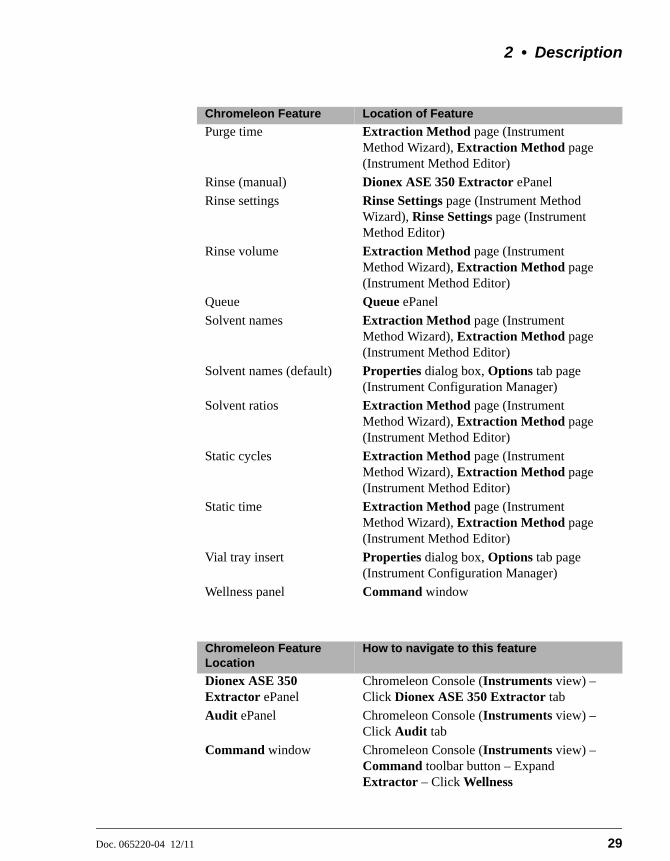
2 • Description
Doc. 065220-04 12/11 29
Purge time Extraction Method page (Instrument Method Wizard), Extraction Method page (Instrument Method Editor)
Rinse (manual) Dionex ASE 350 Extractor ePanel
Rinse settings Rinse Settings page (Instrument Method Wizard), Rinse Settings page (Instrument Method Editor)
Rinse volume Extraction Method page (Instrument Method Wizard), Extraction Method page (Instrument Method Editor)
Queue Queue ePanel
Solvent names Extraction Method page (Instrument Method Wizard), Extraction Method page (Instrument Method Editor)
Solvent names (default) Properties dialog box, Options tab page (Instrument Configuration Manager)
Solvent ratios Extraction Method page (Instrument Method Wizard), Extraction Method page (Instrument Method Editor)
Static cycles Extraction Method page (Instrument Method Wizard), Extraction Method page (Instrument Method Editor)
Static time Extraction Method page (Instrument Method Wizard), Extraction Method page (Instrument Method Editor)
Vial tray insert Properties dialog box, Options tab page (Instrument Configuration Manager)
Wellness panel Command window
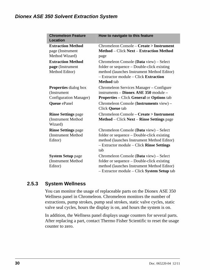
Chromeleon Feature Location
How to navigate to this feature
Dionex ASE 350 Extractor ePanel
Chromeleon Console (Instruments view) – Click Dionex ASE 350 Extractor tab
Audit ePanel Chromeleon Console (Instruments view) – Click Audit tab
Command window Chromeleon Console (Instruments view) – Command toolbar button – Expand Extractor – Click Wellness
Chromeleon Feature Location of Feature
Dionex ASE 350 Solvent Extraction System
30 Doc. 065220-04 12/11
2.5.3 System Wellness
You can monitor the usage of replaceable parts on the Dionex ASE 350 Wellness panel in Chromeleon. Chromeleon monitors the number of extractions, pump strokes, pump seal strokes, static valve cycles, static valve seal cycles, hours the display is on, and hours the system is on.
In addition, the Wellness panel displays usage counters for several parts. After replacing a part, contact Thermo Fisher Scientific to reset the usage counter to zero.
Extraction Method page (Instrument Method Wizard)
Chromeleon Console – Create > Instrument Method – Click Next – Extraction Method page
Extraction Method page (Instrument Method Editor)
Chromeleon Console (Data view) – Select folder or sequence – Double-click existing method (launches Instrument Method Editor) – Extractor module – Click Extraction Method tab
Properties dialog box (Instrument Configuration Manager)
Chromeleon Services Manager – Configure instruments – Dionex ASE 350 module – Properties – Click General or Options tab
Queue ePanel Chromeleon Console (Instruments view) – Click Queue tab
Rinse Settings page (Instrument Method Wizard)
Chromeleon Console – Create > Instrument Method – Click Next – Rinse Settings page
Rinse Settings page (Instrument Method Editor)
Chromeleon Console (Data view) – Select folder or sequence – Double-click existing method (launches Instrument Method Editor) – Extractor module – Click Rinse Settings tab
System Setup page (Instrument Method Editor)
Chromeleon Console (Data view) – Select folder or sequence – Double-click existing method (launches Instrument Method Editor) – Extractor module – Click System Setup tab
Chromeleon Feature Location
How to navigate to this feature

2 • Description
Doc. 065220-04 12/11 31
The Wellness panel is part of the Command window (see Figure 2-9). To view the panel:
1. Press the F8 key or click Command on the toolbar above the ePanel Set.
2. Under Extractor, click Wellness.
2.6 Extraction Process
Before starting an extraction, perform the following preliminary steps. Refer to Chapter 3 for detailed instructions for each step.
• Prepare samples and load them into the cells.
• Place cells in the cell tray.
• Place collection bottles or vials in the collection tray.
• Close the safety shield.
• Create one or more methods.
• Create a sequence.
• Load the method or sequence.
Figure 2-9. Dionex ASE 350 Command Window in Chromeleon

Dionex ASE 350 Solvent Extraction System
32 Doc. 065220-04 12/11
The remainder of this section describes the automatic portion of the extraction process—the steps that the Dionex ASE 350 performs after you press the Start button to begin a run (in Local mode) or click Start on the Sequence Control Bar in Chromeleon (in Remote mode).
These are the key steps in the extraction process:
• Bringing the oven to the correct temperature for the run
• Loading the cell into the oven
• Filling the cell with solvent
• Heating the cell (equilibration)
• Static extraction
• Rinsing with fresh solvent
• Purging solvent from the system
• Relief
• Unloading the cell
You can monitor the progress of a run from these locations:
• The SYSTEM STATUS screen (see Figure 2-10) on the Dionex ASE 350 front panel. To exit the SYSTEM STATUS screen, press Menu. For a description of the screen parameters, see Table 2-2.
Figure 2-10. System Status Screen
Help prompt
SYSTEM STATUS
TIME REMAINING:
CELL #:VOLUME:
TIME STEP:
BTL/VIAL#:SIZE: 1500 PSI
10:00
1
1 1
1 55.0 mL100
STATUS:
LOCAL
FILLING CELL
TEMP: SET 40 C ACTUAL: 40 C
MET #: SEQ #:
PRESSURE:
0:30
MODE: STANDARD

2 • Description
Doc. 065220-04 12/11 33
• The Dionex ASE 350 ePanel in Chromeleon.
The following pages briefly describe each step in the extraction process.
Parameter Description
STATUS The current system status. For example, during a method, this field displays the following status states (in the order listed): Oven Preheat, Filling Cell, Heating Cell, Static, Rinsing, Purge, Relief, and Finished.
MODE The solvent saver mode (pressure or flow). If solvent saver mode is turned off, STANDARD is displayed.NOTE: Two solvent saver modes (fixed volume and gradient) are available only in Chromeleon.
MET # In Local mode: The method currently running is displayed.In Remote mode: “__” is displayed.
SEQ # The sequence currently running.
LOCAL/REMOTE The control mode (Local or Remote).
TIME REMAINING
The time remaining until the current run finishes.
TIME STEP The elapsed time since the start of the current step.
TEMP SET The current temperature set point for the oven.
TEMP ACTUAL The current oven temperature.
PRESSURE The current cell pressure reading. Select the unit of measure on the SYSTEM SETUP screen (see Section B.14) or in the Chromeleon Instrument Configuration program.
CELL # The current sample cell.
CELL SIZE The size of the sample cell.
BTL/VIAL # The current collection bottle or vial.
VOLUME The approximate volume of solvent delivered by the pump.
Table 2-2. System Status Screen Parameters
Dionex ASE 350 Solvent Extraction System
34 Doc. 065220-04 12/11
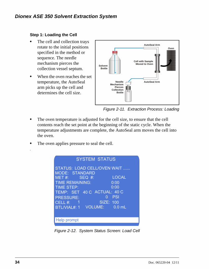
Step 1: Loading the Cell
• The cell and collection trays rotate to the initial positions specified in the method or sequence. The needle mechanism pierces the collection vessel septum.
• When the oven reaches the set temperature, the AutoSeal arm picks up the cell and determines the cell size.
Figure 2-11. Extraction Process: Loading
• The oven temperature is adjusted for the cell size, to ensure that the cell contents reach the set point at the beginning of the static cycle. When the temperature adjustments are complete, the AutoSeal arm moves the cell into the oven.
• The oven applies pressure to seal the cell..
Figure 2-12. System Status Screen: Load Cell
Cell with SampleMoved to Oven
Oven
SolventBottle
AutoSeal Arm
AutoSeal ArmNeedleMechanism
PiercesCollection
Bottle
Help prompt
SYSTEM STATUS
TIME REMAINING:
CELL #:VOLUME:
TIME STEP:
BTL/VIAL#:SIZE:
0 PSI
0:00
1 1
0:00
0.0 mL100
STATUS:
LOCAL
LOAD CELL/OVEN WAIT ......
TEMP: SET 40 C ACTUAL: 40 C
MET #: SEQ #:
PRESSURE:
MODE: STANDARD
2 • Description
Doc. 065220-04 12/11 35
NOTE The oven begins heating to the preprogrammed set pointimmediately after a method is loaded (before Start ispressed to begin the run). Cell loading begins after Startis pressed, when the oven is within 1 °C of the set point.
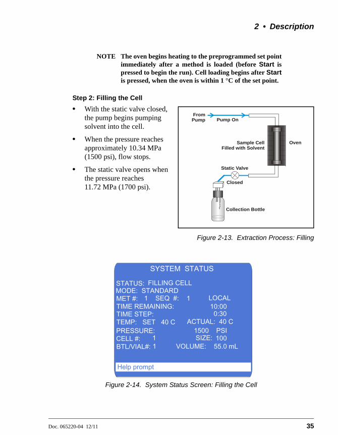
Step 2: Filling the Cell
• With the static valve closed, the pump begins pumping solvent into the cell.
• When the pressure reaches approximately 10.34 MPa (1500 psi), flow stops.
• The static valve opens when the pressure reaches 11.72 MPa (1700 psi).
Figure 2-13. Extraction Process: Filling
Figure 2-14. System Status Screen: Filling the Cell
Sample Cell Filled with Solvent
Oven
Collection Bottle
From Pump Pump On
Static Valve
Closed
Help prompt
SYSTEM STATUS
TIME REMAINING:
CELL #:VOLUME:
TIME STEP:
BTL/VIAL#:SIZE: 1500 PSI
10:00
1
1 1
1 55.0 mL100
STATUS:
LOCAL
FILLING CELL
TEMP: SET 40 C ACTUAL: 40 C
MET #: SEQ #:
PRESSURE:
0:30
MODE: STANDARD
Dionex ASE 350 Solvent Extraction System
36 Doc. 065220-04 12/11
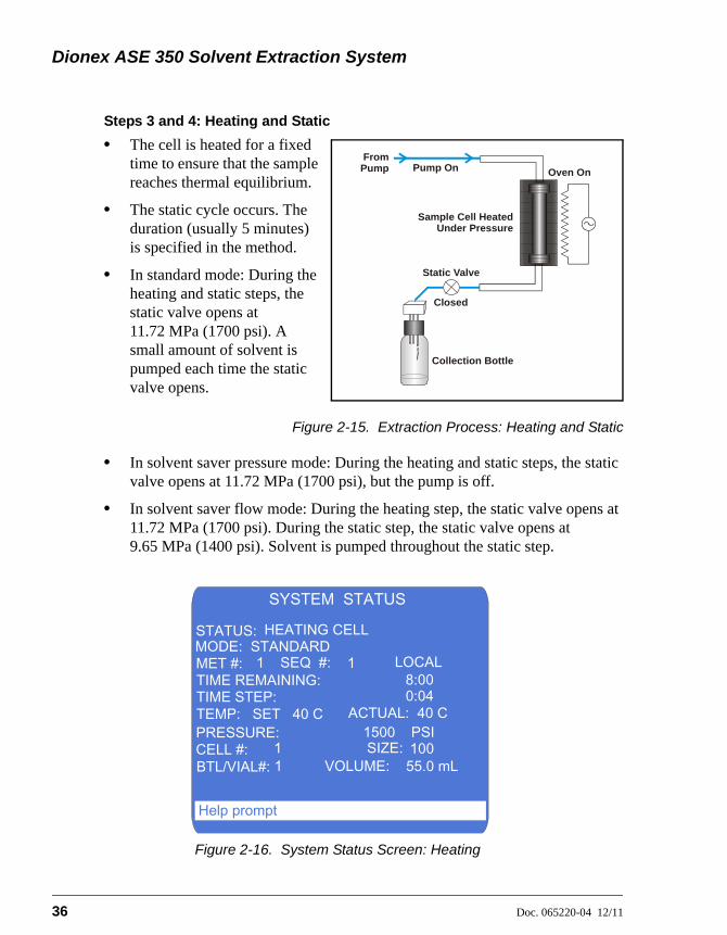
Steps 3 and 4: Heating and Static
• The cell is heated for a fixed time to ensure that the sample reaches thermal equilibrium.
• The static cycle occurs. The duration (usually 5 minutes) is specified in the method.
• In standard mode: During the heating and static steps, the static valve opens at 11.72 MPa (1700 psi). A small amount of solvent is pumped each time the static valve opens.
Figure 2-15. Extraction Process: Heating and Static
• In solvent saver pressure mode: During the heating and static steps, the static valve opens at 11.72 MPa (1700 psi), but the pump is off.
• In solvent saver flow mode: During the heating step, the static valve opens at 11.72 MPa (1700 psi). During the static step, the static valve opens at 9.65 MPa (1400 psi). Solvent is pumped throughout the static step.
Figure 2-16. System Status Screen: Heating
Sample Cell Heated Under Pressure
Oven On
Collection Bottle
Pump On
Static Valve
Closed
From Pump
Help prompt
SYSTEM STATUS
TIME REMAINING:
CELL #:VOLUME:
TIME STEP:
BTL/VIAL#:SIZE: 1500 PSI
8:00
1
1 1
1 55.0 mL100
STATUS:
LOCAL
HEATING CELL
TEMP: SET 40 C ACTUAL: 40 C
MET #: SEQ #:
PRESSURE:
0:04
MODE: STANDARD

2 • Description
Doc. 065220-04 12/11 37
Step 5: Rinsing the Cell
• The static valve opens and the extract flows into the collection vessel.
• If desired, fresh solvent (usually 50% to 100% of the cell volume) can then be pumped through the cell. In solvent saver mode (pressure and flow), the default rinse volume is zero.
Figure 2-17. Extraction Process: Rinsing
Figure 2-18. System Status Screen: Rinsing
Solvent RinsedThrough Cell
Oven
Solvent and ExtractCollected in Bottle
Pump On
Static Valve
Open
From Pump
Help prompt
SYSTEM STATUS
TIME REMAINING:
CELL #:VOLUME:
TIME STEP:
BTL/VIAL#:SIZE: 20 PSI
2:00
1
1 1
1 55.0 mL100
STATUS:
LOCAL
RINSING
TEMP: SET 40 C ACTUAL: 40 C
MET #: SEQ #:
PRESSURE:
0:30
MODE: STANDARD
Dionex ASE 350 Solvent Extraction System
38 Doc. 065220-04 12/11
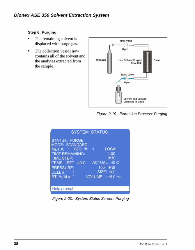
Step 6: Purging
• The remaining solvent is displaced with purge gas.
• The collection vessel now contains all of the solvent and the analytes extracted from the sample.
Figure 2-19. Extraction Process: Purging
Figure 2-20. System Status Screen: Purging
Last Solvent Purgedfrom Cell
Oven
Solvent and ExtractCollected in Bottle
Static Valve
Purge Valve
Open
Nitrogen
Open
Help prompt
SYSTEM STATUS
TIME REMAINING:
CELL #:VOLUME:
TIME STEP:
BTL/VIAL#:SIZE: 100 PSI
1:00
1
1 1
1 115.0 mL100
STATUS:
LOCAL
PURGE
TEMP: SET 40 C ACTUAL: 40 C
MET #: SEQ #:
PRESSURE:
0:30
MODE: STANDARD

2 • Description
Doc. 065220-04 12/11 39
Step 7: Relief
• Residual pressure is released from the sample cell.
• Pressure is vented from the system.
Figure 2-21. Extraction Process: Relief
Figure 2-22. System Status Screen: Relief
Residual PressureReleased from Cell
Oven
Collection Bottle
To Waste
Pressure Relief Valve
Open
Open
Help prompt
SYSTEM STATUS
TIME REMAINING:
CELL #:VOLUME:
TIME STEP:
BTL/VIAL#:SIZE: 0 PSI
0:30
1
1 1
1 115.0 mL100
STATUS:
LOCAL
RELIEF
TEMP: SET 40 C ACTUAL: 40 C
MET #: SEQ #:
PRESSURE:
0:30
MODE: STANDARD
Dionex ASE 350 Solvent Extraction System
40 Doc. 065220-04 12/11
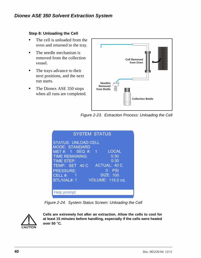
Step 8: Unloading the Cell
• The cell is unloaded from the oven and returned to the tray.
• The needle mechanism is removed from the collection vessel.
• The trays advance to their next positions, and the next run starts.
• The Dionex ASE 350 stops when all runs are completed.
Figure 2-23. Extraction Process: Unloading the Cell
Figure 2-24. System Status Screen: Unloading the Cell
Cells are extremely hot after an extraction. Allow the cells to cool forat least 15 minutes before handling, especially if the cells were heatedover 50 °C.
Cell Removed from Oven
NeedlesRemoved
from Bottle
Collection Bottle
Help prompt
SYSTEM STATUS
TIME REMAINING:
CELL #:VOLUME:
TIME STEP:
BTL/VIAL#:SIZE: 0 PSI
0:30
1
1 1
1 115.0 mL100
STATUS:
LOCAL
UNLOAD CELL
TEMP: SET 40 C ACTUAL: 40 C
MET #: SEQ #:
PRESSURE:
0:30
MODE: STANDARD
2 • Description
Doc. 065220-04 12/11 41
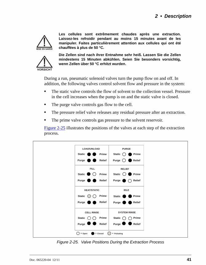
During a run, pneumatic solenoid valves turn the pump flow on and off. In addition, the following valves control solvent flow and pressure in the system:
• The static valve controls the flow of solvent to the collection vessel. Pressure in the cell increases when the pump is on and the static valve is closed.
• The purge valve controls gas flow to the cell.
• The pressure relief valve releases any residual pressure after an extraction.
• The prime valve controls gas pressure to the solvent reservoir.
Figure 2-25 illustrates the positions of the valves at each step of the extraction process.
Les cellules sont extrêmement chaudes après une extraction.Laissez-les refroidir pendant au moins 15 minutes avant de lesmanipuler. Faites particulièrement attention aux cellules qui ont étéchauffées à plus de 50 °C.
Die Zellen sind nach ihrer Entnahme sehr heiß. Lassen Sie die Zellenmindestens 15 Minuten abkühlen. Seien Sie besonders vorsichtig,wenn Zellen über 50 °C erhitzt wurden.
Figure 2-25. Valve Positions During the Extraction Process
RELIEF
HEAT/STATIC
LOAD/UNLOAD PURGE
Prime
Prime
Prime
Prime
Purge Purge
Purge
Purge
Purge Purge
Purge
Purge
Static
Static
Static Static
Static
Static
StaticStatic
Relief
Relief
Relief
Relief
Relief
Relief
Relief
Relief
Prime
Prime
Prime
Prime
FILL
CELL RINSE SYSTEM RINSE
IDLE
PulsatingOpen Closed
Dionex ASE 350 Solvent Extraction System
42 Doc. 065220-04 12/11
2.7 Method and Sequence Control
Before starting a run, you must select a method that defines the operating conditions for the run. A method specifies the following parameters:
• Oven temperature
• Time allowed for the sample to reach thermal equilibrium
• Static time
• Number of static cycles
• Amount of solvent to rinse through the cell
• Purge time
• Solvent types and ratios (if more than one solvent reservoir is installed)
• Cell material (stainless steel or zirconium)
• Standard or solvent saver mode
The Dionex ASE 350 can store up to 24 methods. Section 3.2.1 describes how to create methods from the Dionex ASE 350 front panel.
For a series of runs, it is more efficient to define a sequence. A sequence specifies the method to run on each sample in the sequence, the sample cell assigned to each collection vessel, and the rinse status after each sample run. The Dionex ASE 350 can store up to 24 sequences. Section 3.2.3 describes how to create sequences from the Dionex ASE 350 front panel.
The Dionex ASE 350 provides two control modes:
• Method control runs the same method on each consecutive sample loaded in the tray.
• Sequence control runs a series of methods according to the sequence definition.
NOTE For an overview of how to control the Dionex ASE 350with Chromeleon, see Section 3.3. For detailedinstructions, refer to the Chromeleon Help.

2 • Description
Doc. 065220-04 12/11 43
2.7.1 Solvent Saver Mode
Solvent saver mode is an extraction method available exclusively with the Dionex ASE 350. Solvent saver methods are recommended for:
• Modifying and enhancing existing extraction methods
• Exploring new extraction methods
• Simulating extraction on a small scale before scale-up to a plant scale extraction module
There are four solvent saver options; two options (the fixed volume and gradient modes) are available only in Chromeleon.
• The pressure mode is a static mode of extraction that minimizes solvent usage by maintaining a fixed cell pressure and eliminating the introduction of fresh solvent during the heating and static cycles. This mode uses less solvent than any other Dionex ASE 350 extraction mode.
• The flow mode is a continuous dynamic extraction mode in which small aliquots of solvent are delivered to the cell at the specified flow rate throughout the static step. The cell temperature remains constant throughout the run.
• The fixed volume mode specifies the solvent volume to be used in an extraction. After this volume has been pumped to the cell, the pump is turned off.
• The gradient mode is an extension of the flow mode. In addition to the flow rate used during the static step, solvents A, B, and C have start and end proportions that produce a solvent gradient.
You can select the extraction mode in these locations:
• The METHOD EDITOR screen (see Figure 3-19) on the Dionex ASE 350 front panel.
– or –
• The Extraction Method page in the Chromeleon Instrument Method Wizard (see Figure 2-26).

Dionex ASE 350 Solvent Extraction System
44 Doc. 065220-04 12/11
Solvent Saver Pressure Mode
The solvent saver pressure mode is a simplified extraction protocol. The sample cell is filled inside the oven; when the fill pressure of 10.34 MPa (1500 psi) is reached, the pump is turned off. The cell (and solvent) are heated at the extraction temperature for a set time. When the pressure reaches 11.72 MPa (1700 psi), the static valve opens to relieve pressure by dispensing some of the solvent out of the cell and into the collection vessel. The run proceeds with no additional fresh solvent entering the
Figure 2-26. Example Chromeleon Extraction Method Page

2 • Description
Doc. 065220-04 12/11 45
sample cell and no additional static cycles. The default rinse volume is zero; however, the user can add a rinse at the end of the cycle, if needed.
The solvent saver pressure mode is recommended for lipid extraction methods with ASE Prep CR Resin (P/N 080024). Although standard extraction methods can be used for this application, use of the pressure mode reduces solvent usage.
Solvent Saver Flow Mode
In the solvent saver flow mode, the pump delivers small aliquots of solvent to the cell, mimicking a dynamic extraction during the static period while maintaining all the steps of a standard accelerated solvent extraction during the filling and heating steps. The sample cell is filled inside the oven, and the heating step then begins. The cell (and solvent) are heated to the extraction temperature for a set time and the static step begins. The pump meters in solvent at the set flow rate; thus, the heated solvent is in contact with the sample as well as the small aliquots of incoming solvent. If the pressure in the cell exceeds 10.34 MPa (1400 psi) during the static step, the static valve opens to release some solvent, while fresh solvent increases the cell pressure and the run proceeds. As with the solvent saver pressure mode, the flow mode also has just one static cycle.
Because fresh solvent is added in small aliquots throughout the entire static step, the recommended rinse volume is zero (the default). However, you can include a rinse at the end of the static step.
Solvent Saver Fixed Volume Mode
NOTE Operation in the solvent saver fixed volume moderequires Chromeleon software.
In the solvent saver fixed volume mode, you specify the total amount of solvent to be used during the extraction. Only one static cycle is allowed. Although the rinse volume parameter is not available in this mode, it is possible to perform a rinse by selecting a solvent volume that exceeds the cell size. When the sample cell is placed in the oven, solvent is delivered to the cell until either the selected solvent volume is reached or the cell is full. Method parameters, including the solvent volume, are selected in the Chromeleon Instrument Method Wizard.

Dionex ASE 350 Solvent Extraction System
46 Doc. 065220-04 12/11
• If you select a solvent volume that is less than the cell volume: The pump stops at the selected volume and is turned off for the remainder of the extraction time. At the end of the extraction time, nitrogen purges the cell of all the solvent into the collection bottle.
• If you select a solvent volume that is more than the cell volume: After the cell is filled, the extraction continues as a standard extraction until the selected volume is reached. If the selected volume has not been reached at the end of the static time, the pump delivers fresh solvent (acting like a final rinse) until the volume has been met.
Solvent Saver Gradient Mode
NOTE Operation in the solvent saver gradient moderequires Chromeleon software.
In the solvent saver gradient mode, the extraction begins with one solvent composition and finishes with a different solvent composition. The solvent transition takes place during the static cycle time, and is controlled by the flow parameter. Method parameters, including the start and end ratios for each solvent, are selected in the Chromeleon Instrument Method Wizard.
For example, assume that you need to extract with solvent A and transition to solvent B at a flow rate of 2.0 mL/min for 8 minutes. The sample cell is filled with solvent A inside the oven, and the heating step then begins. The cell (and solvent) are heated to the extraction temperature for a set time and the static step begins. The solvent composition is 100% A at the start of the static time. At 2 minutes into the static time, the composition reaches 75% A and 25% B. At 4 minutes, the ratio is 50% A and 50% B, and so on. At the end of the static time, the solvent composition is 100% B. Only one static cycle is allowed. If any rinse volume is selected, it will be done with the end ratio, which in this case would be 100% B.

Doc. 065220-04 12/11 47
3 • Operation and Maintenance
3.1 Preparing to Run
3.1.1 Selecting and Preparing Extraction Solvents
Precautions
Do not use solvents with an autoignition point below 200 °C. The tablebelow lists some solvents that should not be used with the DionexASE 350. If you have a question about solvent suitability, contactThermo Fisher Scientific.
Do Not Use These Solvents Autoignition Point
Carbon disulfide: CS2 100 °C
Diethylether: (C2H5)2O 180 °C
1,4-dioxane: C4H8O2 180 °C
N'utilisez pas de solvants ayant un point éclair inférieur à 200 °C. Letableau ci-dessous liste quelques solvants qui ne doivent pas êtreutilisés avec l'Dionex ASE 350. Contactez Thermo Fisher Scientific sivous avez un doute concernant l’usage d’un solvant absent de la liste.
Solvants à ne pas utiliser Point d'auto-inflammation
Disulfure de carbone: CS2 100 °C
Éther diéthylique: (C2H5)2O 180 °C
1,4-dioxane: C4H8O2 180 °C
Verwenden Sie keine Lösungsmittel, deren Selbstentzündungs-temperatur unter 200°C liegt. Die untenstehende Tabelle zeigt einigeLösungsmittel, die Sie nicht mit dem Dionex ASE 350 verwendensollten. Bei Fragen zur Eignung von Lösungsmitteln wenden Sie sichbitte an Thermo Fisher Scientific.
Nicht zu verwendendeLösungsmittel
Selbstentzündungstemperatur
Kohlendisulfid: CS2 100 °C
Diethyläther: (C2H5)2O 180 °C
1,4-dioxan: C4H8O2 180 °C

Dionex ASE 350 Solvent Extraction System
48 Doc. 065220-04 12/11
Guidelines for Selecting and Preparing Solvents
• When developing a new method, select a solvent or solvent mixture that has a high solubility for the analytes of interest, but not for the sample matrix. If you have been using another method (Soxhlet, for example), use the same solvent with the Dionex ASE 350 that you used with the other method.
• Use HPLC-grade or pesticide-grade solvents.
• Use organic or aqueous solvents.
• Use single-component or multiple-component solvents.
• Solvents do not usually need to be degassed. Degas solvents only if the analyte of interest oxidizes easily.
• If Viton external O-rings are installed in the cell end caps, do not use acetone or other ketones.
• Although the zirconium components in the Dionex ASE 350 flow path are more resistant to acids and bases at elevated temperatures than other metallic materials, follow these guidelines to prevent degradation and ensure optimum performance:
a. As a general rule, strong mineral acids such as hydrochloric acid should not be used (at any concentration) as extraction solvents. This is because there are stainless steel components in the flow path of the system (for example, the pump head) that will corrode when used with strong acids. Sulfuric acid and nitric acid can be pumped as a solvent at concentrations less than 0.1% by volume. For more details about acids that can be pumped as solvents, see Table 3-1.
b. Strong bases such as sodium hydroxide or potassium hydroxide can be pumped as extraction solvents at concentrations less than 0.1% by volume. For more details about bases that can be pumped as solvents, see Table 3-1.
c. Weak acids such as phosphoric or acetic acid can be used as extraction solvents in small percentages (<5% by volume). Weak
Using corrosive acids or bases can damage stainless steel cells andwill void the product warranty.

3 • Operation and Maintenance
Doc. 065220-04 12/11 49
bases such as ammonia can be used at small percentages (<5% by volume).
d. Noncorrosive additives such as buffers (acetate, phosphate, etc.) can be used as extraction solvents at moderate percentages.
e. In some cases, nitric or hydrochloric acid can be added directly to the sample before it is placed into a zirconium cell. (Do not use a stainless steel cell.) For example, 1 to 2 mL of 5% to 10% HCl can be added directly to a soil sample before it is loaded into a zirconium cell for extraction.
f. Table 3-1 lists the allowable concentrations for several acids and bases. If a sample needs to be treated with acids stronger than the concentrations here, pretreat the sample with the concentrated acid before loading it into a zirconium cell. (Do not use a stainless steel cell.) For more details about sample preparation, see Section 3.1.3.
Acid or Base Con-centration
Okay to pump from solvent reservoir? (Use SST or Zr cells)
Add to sample and transfer to Zr cell? (Do not use SST cells)
Add to sample with ASE Prep CR and transfer to Zr cell? (Do not use SST cells)
HCl 8 M No No Yes
HCl 10% No Yes Yes
HCl 0.1 M No Yes Yes
NaOH 8 M No No N/A
NaOH 10% No Yes N/A
NaOH 0.1 M Yes Yes N/A
H2SO4 8 M No No Yes
H2SO4 10% No Yes Yes
H2SO4 5% solution Yes Yes Yes
H2SO4 0.1 M Yes Yes Yes
Table 3-1. Guidelines for Use of Acids and Bases with the Dionex ASE 350

Dionex ASE 350 Solvent Extraction System
50 Doc. 065220-04 12/11
KOH 8 M No No N/A
KOH 10% No Yes N/A
KOH 0.1 M Yes Yes N/A
HNO3 8 M No No Yes
HNO3 10% Yes Yes Yes
HNO3 0.1 M Yes Yes Yes
NH4OH 8 M No No N/A
NH4OH < 5% Yes Yes N/A
NH4OH 0.1 M Yes Yes N/A
Trifluoroacetic acid < 5%
Yes Yes Yes
Acetic acid < 5% Yes Yes Yes
Phosphoric acid <5%
Yes Yes Yes
If acids, bases, salts, or buffers are used as extraction solvents, rinsethe system with 100% polar organic solvent (for example, acetone ormethanol) or distilled water before turning off the power.
Acid or Base Con-centration
Okay to pump from solvent reservoir? (Use SST or Zr cells)
Add to sample and transfer to Zr cell? (Do not use SST cells)
Add to sample with ASE Prep CR and transfer to Zr cell? (Do not use SST cells)
Table 3-1. Guidelines for Use of Acids and Bases with the Dionex ASE 350

3 • Operation and Maintenance
Doc. 065220-04 12/11 51
3.1.2 Filling the Solvent Reservoir
The solvent reservoir tray can hold up to three reservoirs. Follow the procedure below to fill each reservoir.
1. Fill the solvent reservoir (P/N 045901) with prepared solvent to the level indicated in Figure 3-1.
Use only Thermo Fisher Scientific solvent reservoirs. These are glassreservoirs with a plastic, shatterproof coating. Make sure the pressureapplied to the reservoirs does not exceed 0.07 MPa (10 psi).
Utilisez uniquement des réservoirs à solvant Thermo Fisher Scientific.Ce sont des réservoirs en verre à revêtement incassable en plastique.Veillez à ce que la pression exercée sur ces réservoirs ne dépasse pas0,07 MPa.
Verwenden Sie ausschließlich die Lösemittelbehälter von ThermoFisher Scientific. Dabei handelt es sich um Glasbehälter mit einersplittersicheren Plastikbeschichtung. Vergewissern Sie sich, daß derDruck, der auf die Behälter ausgeübt wird, 0,07 MPa nicht übersteigt.
Never fill the solvent reservoir or disconnect the tubing connectionsto the solvent and gas connectors (see Figure 3-1) during a run orrinse cycle. At these times, the solvent reservoir is pressurized. If youremove the cap when the reservoir is pressurized, the Dionex ASE 350may not operate to specification.
The solvent level in the reservoir must remain below the gas line. Thisprevents solvent from coming into contact with the pneumatic valves.

Dionex ASE 350 Solvent Extraction System
52 Doc. 065220-04 12/11
Figure 3-1. Solvent Reservoir Connections
End-Line Filter

3 • Operation and Maintenance
Doc. 065220-04 12/11 53
2. Set the reservoir in the designated location in the Dionex ASE 350 solvent reservoir tray (see Figure 3-2).
3. Insert the solvent line extending from the underside of the reservoir cap assembly into the reservoir (see Figure 3-1). Make sure the end-line filter rests on the bottom of the reservoir.
If necessary, loosen the fitting on top of the stopper, gently pull on the solvent line to bring more tubing into the reservoir, and then tighten the fitting.
4. Hand-tighten the gray lock ring cap securely over the stopper.
NOTE Always connect the solvent line to the solventconnector first, and then the gas line to the gasconnector. When disconnecting the lines, firstdisconnect the gas line and then the solvent line.This prevents inadvertent pressurization of thereservoir and solvent flow when it is notconnected.
To refill a solvent reservoir:
It is not necessary to disconnect the solvent and gas lines before refilling the reservoir. Loosen the gray lock ring cap, and then remove the stopper and attached tubing from the reservoir. Remove the reservoir from the solvent reservoir tray and place it on a bench for refilling.
Figure 3-2. Designated Locations for Solvent Reservoirs
Solvent A
Solvent B
Solvent C
Dionex ASE 350 Solvent Extraction System
54 Doc. 065220-04 12/11
3.1.3 Preparing the Sample
If you have successfully followed a particular sample pretreatment procedure for another extraction method, continue using this procedure with the Dionex ASE 350. If you have never run an extraction—or if you are preparing a new sample—follow the guidelines here. This section discusses two sample pretreatment procedures:
• Samples that are dry, wet, or liquid should be mixed with a drying or dispersing agent before being loaded into the cells.
• Samples with large particle sizes should be ground before being loaded into the cells.
NOTE: Most problems with the ASE (accelerated solvent extraction) process are caused by errors made during the sample preparation phase. To obtain high quality analytical results, pay careful attention when preparing samples. For more information, see Appendix E.
Guidelines for Selecting a Drying or Dispersing Agent
• The sample preparation guidelines on page 55 recommend the use of pelletized diatomaceous earth (DE) (P/N 062819) as a drying agent. DE provides a clean transfer of the mixtures to the cell, and extracts well.
• Although sodium sulfate is readily available, do not use it in Dionex ASE 350 cells. The use of sodium sulfate with very wet samples (30% moisture) will result in clogging of system components (such as the solvent line or needles) with recrystallized sodium sulfate. This occurs particularly if a mixed solvent with a polar component such as methanol or acetone is used. In these cases, use DE as a drying agent and mix it with the sample before loading into the sample cell. (Alternately, DE can be used as a drying agent in the cell in place of sodium sulfate for all levels of moisture.)
• For very wet samples, regardless of which drying agent is used, you may add sodium sulfate to the collection vessels after collection and then pass the extracts through either a drying column or drying cartridge to dry the extract completely. At the temperatures used during Dionex ASE 350 extractions, more water is co-extracted than with other extraction procedures. To ensure good analyte recovery,

3 • Operation and Maintenance
Doc. 065220-04 12/11 55
thoroughly rinse the sodium sulfate from the collection vessel and the cleanup column.
• If a sample needs to be treated with acids stronger than the concentrations listed in Table 3-1, pretreat the sample with the concentrated acid before loading it into the cell. After the pretreatment, mix the sample with ASE Prep CR Resin (P/N 080024) to partially neutralize the acid to approximately 0.1 M. The sample may need to be mixed with DE to absorb water, depending on how much acid was used to pretreat the sample.
For example, if a food sample is treated with 10 mL of 8 M HCl, mix the liquid hydrolysate with 30 to 40 g of ASE Prep CR and 15 g of DE. When the sample is thoroughly mixed, add it to a zirconium cell. (Do not use a stainless steel cell.) Use this ratio of acid to ASE Prep CR whenever using strong acids for pretreatment of samples.
Sample Preparation with a Drying or Dispersing Agent
The following mixtures are recommendations only; adjust the proportions as required.
• If the sample appears dry, use this mixture:
4 grams sample to 1 gram DE
Mix the sample and the DE thoroughly in a small bottle, beaker, or mortar.
• If the sample appears wet, use this mixture:
4 grams sample to 2 grams DE
Mix the sample and the DE thoroughly in a small bottle, beaker, or mortar.
• If the sample is pure liquid, use 5 grams sample to 3 grams DE.
Fill the cell with DE and then add the sample.
NOTE Certain pure liquid samples may be mixed withdrying or dispersing agents other than DE. Fora current list of approved materials, contactThermo Fisher Scientific.

Dionex ASE 350 Solvent Extraction System
56 Doc. 065220-04 12/11
Guidelines for Grinding
• For an efficient extraction to occur, the solvent must make contact with the target analytes. The more surface area that can be exposed in a sample, the faster the extraction will occur. Therefore, samples with large particle sizes should be ground prior to extraction. Often a large, representative sample can be ground, after which weighed portions of the ground sample can be used for extraction.
• Soil and sediment samples usually do not need to be ground, but it may be necessary to remove stones or sticks from the samples prior to extraction.
• Polymer samples must be in a ground state for an efficient extraction of additive compounds. Materials such as polymers and rubbers are best ground at reduced temperatures; for example, while chilling with liquid nitrogen.
• Animal or plant tissue samples can be homogenized using any procedure, including a blender or tissue homogenizer.
Sample Preparation by Grinding
Grind the sample with one of the following tools: a conventional mortar and pestle, an electric grinder, or an electric mill. For the most efficient extraction, grind until particles are smaller than 1 mm.
3.1.4 Selecting the Sample Cell
Sample cells are available in the following sizes: 1 mL, 5 mL, 10 mL, 22 mL, 34 mL, 66 mL, and 100 mL. All cells are available in stainless steel. Two cell sizes (66 mL and 100 mL) are available in zirconium, also.
The cell size does not affect the extraction time, but it does determine how much solvent is used; because the cell is filled with solvent during the extraction, larger cells require more solvent. Also, a cell that is partially filled with sample requires more solvent than a full cell.
In general, when choosing a cell size:
• Select the smallest cell that holds enough sample to produce accurate extraction results.
• Take into account any drying or dispersing agents, because these increase the volume of the sample.
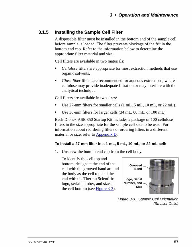
3 • Operation and Maintenance
Doc. 065220-04 12/11 57
3.1.5 Installing the Sample Cell Filter
A disposable filter must be installed in the bottom end of the sample cell before sample is loaded. The filter prevents blockage of the frit in the bottom end cap. Refer to the information below to determine the appropriate filter material and size.
Cell filters are available in two materials:
• Cellulose filters are appropriate for most extraction methods that use organic solvents.
• Glass-fiber filters are recommended for aqueous extractions, where cellulose may provide inadequate filtration or may interfere with the analytical technique.
Cell filters are available in two sizes:
• Use 27-mm filters for smaller cells (1 mL, 5 mL, 10 mL, or 22 mL).
• Use 30-mm filters for larger cells (34 mL, 66 mL, or 100 mL).
Each Dionex ASE 350 Startup Kit includes a package of 100 cellulose filters in the size appropriate for the sample cell size to be used. For information about reordering filters or ordering filters in a different material or size, refer to Appendix D.
To install a 27-mm filter in a 1-mL, 5-mL, 10-mL, or 22-mL cell:
1. Unscrew the bottom end cap from the cell body.
To identify the cell top and bottom, designate the end of the cell with the grooved band around the body as the cell top and the end with the Thermo Scientific logo, serial number, and size as the cell bottom (see Figure 3-3).
Figure 3-3. Sample Cell Orientation(Smaller Cells)
Logo, SerialNumber, and
Size
GroovedBand

Dionex ASE 350 Solvent Extraction System
58 Doc. 065220-04 12/11
2. Place a 27-mm filter in the center of the cell bottom end cap (see Figure 3-4).
3. To prevent leaks, check that no part of the filter overlaps onto the PEEK seal.
Figure 3-4. Installing a 27-mm Cell Filter
4. Carefully place the cell body over the bottom end cap, screw the body onto the end cap, and hand-tighten.
To install a 30-mm filter in a 34-mL, 66-mL, or 100-mL cell:
1. Unscrew the top end cap from the cell body. Verify that an end cap is installed on the bottom of the cell.
To identify the cell top and bottom, designate the end of the cell with the grooved band around the body as the cell top and the end with the Thermo Scientific logo, serial number, and size as the cell bottom (see Figure 3-5).
Figure 3-5. Sample Cell Top (Larger Cells)
Always tighten the cell end caps by hand. Use of a wrench or othertool can damage the cell, as well as the seals inside the cell end caps,and will void the product warranty.
Always tighten the cell end caps by hand. Use of a wrench or othertool can damage the cell, as well as the seals inside the cell end caps,and will void the product warranty.
Do not place the 30-mm filter in the bottom end cap before installingthe cap; this creates an improper seal and allows leaks.
27-mm Filter
PEEKSeal
Bottom Cap of a1-, 5-, 10-, or 22-mL Cell
GroovedBand
Logo, SerialNumber, and
Size

3 • Operation and Maintenance
Doc. 065220-04 12/11 59
2. Follow the steps in Figure 3-6 to install the 30-mm filter.
NOTE The procedure for installing 30-mm filters instainless steel and zirconium cells is the same. Thephotos in Figure 3-6 show a zirconium cell.
3.1.6 Filling the Sample Cell
Precautions:
• When filling the cell with sample, keep the cell body threads as clean as possible to prevent thread fouling and extend the life of the cell.
• Also make sure that the ends of the cell body and the seals in the end caps are clean; if debris remains here, it will damage the cell body and/or allow leaks during the run.
To fill a sample cell:
1. Carefully load the sample into the top of the cell, using the funnel provided in the Dionex ASE 350 Startup Kit. To accommodate different sample cell sizes, three funnels (with different inner diameters) are available (see Figure 3-7).
Figure 3-6. Installing a 30-mm Cell Filter in a 34-mL, 66-mL, or 100-mL Cell
Insert a 30-mm filter into the cell at a slight angle.
Position the filter insertion tool (P/N 056929) over the filter.
Slowly push the insertion tool straight into the cell.
Push down until the filter is in full contact with the end cap.

Dionex ASE 350 Solvent Extraction System
60 Doc. 065220-04 12/11
2. (Optional) To reduce the amount of solvent used during the extraction, fill any void volume in the cell with an inert material such as Ottawa sand (Fisher S23-3).
3. Using a soft brush or cloth, wipe all debris off the threads.
4. Screw the top end cap onto the cell body. Hand-tighten the end cap.
5. Check the ends of each cell end cap to verify that the O-rings are in place and are in good condition (see Figure 3-8).
• If an O-ring is dislodged, press it into place, using the O-ring insertion tool (P/N 049660) provided in the Dionex ASE 350 Ship Kit (P/N 066060).
Figure 3-8. Inspecting Cell O-Rings
Figure 3-7. Sample Funnels
Always tighten the cell end caps by hand. Use of a wrench or othertool can damage the cell, as well as the seals inside the cell end caps,and will void the product warranty.
Funnel for 1-mL cells(P/N 068076)
Funnel for 5-, 10-, and 22-mL cells (P/N 068075)
Funnel for 34-, 66-, and 100-mL cells (P/N 056699)
Verify that O-ringsare installed andin good condition

3 • Operation and Maintenance
Doc. 065220-04 12/11 61
• If an O-ring is missing, place a new O-ring over the opening in the end of the cell end cap. Press the O-ring into place, using the O-ring insertion tool (see Figure 3-9). For part numbers for O-rings, see Appendix D.
• If an O-ring has a hole size of less than 0.5 mm, replace it. If a white PTFE O-ring is discolored, replace it (see page 61).
Figure 3-9. Installing a Cell End Cap O-Ring
To replace a cell end cap O-ring:
1. Locate the small flathead screwdriver (P/N 046985) and the O-ring insertion tool (P/N 049660) in the Dionex ASE 350 Ship Kit (P/N 066060).
2. Insert the tip of the screwdriver into the end cap and carefully pick out the O-ring. (This may be easier to do if you first remove the cap from the cell body and place it flat on the workbench.)
3. Place a new O-ring (P/N 049457, pkg. of 50 PTFE O-rings; P/N 056325, pkg. of 50 Viton O-rings) over the opening in the end of the cell end cap. Press the O-ring into place, using the O-ring insertion tool (see Figure 3-9).
Do not attach any labels to the cell. The cells fit snugly in the ovenduring the extraction process and a label may cause misalignment. Inaddition, the high temperatures used during extraction can damagethe label. For sample identification, reference the serial numberetched on the cell or write on the cell body with a marking pen.
Be careful not to scratch the interior of the cell end cap wheninstalling or removing the cell O-ring. Scratches on the sealingsurface will prevent the O-ring from sealing properly and may result inleaks during operation.
O-Ring Insertion Tool(P/N 049660)
Place O-ring in openingand press into place with insertion tool.
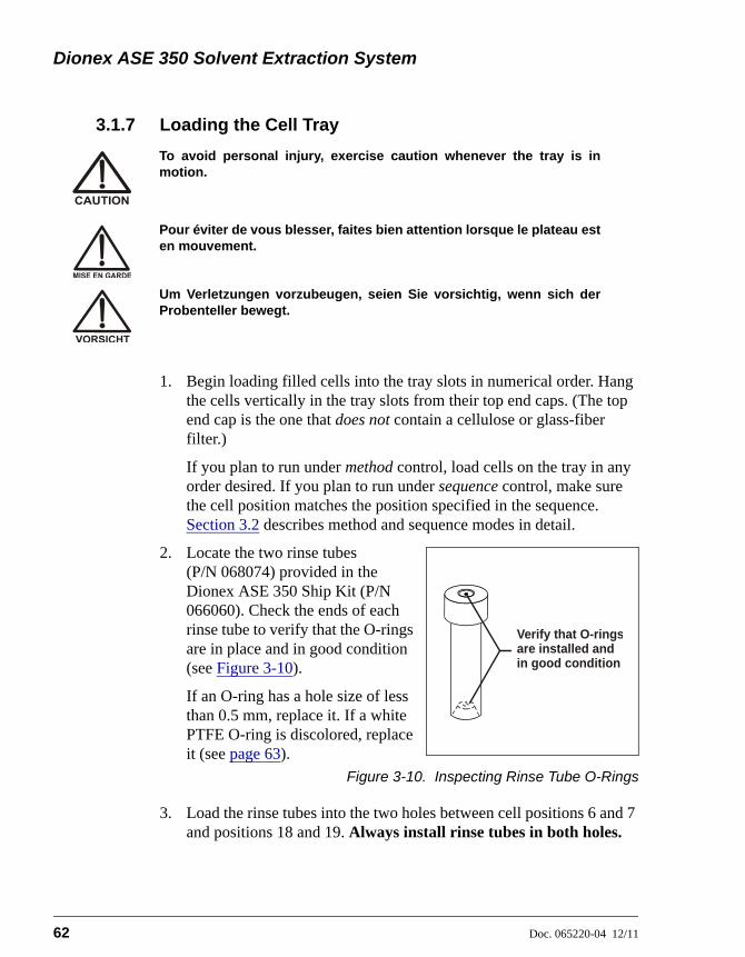
Dionex ASE 350 Solvent Extraction System
62 Doc. 065220-04 12/11
3.1.7 Loading the Cell Tray
1. Begin loading filled cells into the tray slots in numerical order. Hang the cells vertically in the tray slots from their top end caps. (The top end cap is the one that does not contain a cellulose or glass-fiber filter.)
If you plan to run under method control, load cells on the tray in any order desired. If you plan to run under sequence control, make sure the cell position matches the position specified in the sequence. Section 3.2 describes method and sequence modes in detail.
2. Locate the two rinse tubes (P/N 068074) provided in the Dionex ASE 350 Ship Kit (P/N 066060). Check the ends of each rinse tube to verify that the O-rings are in place and in good condition (see Figure 3-10).
If an O-ring has a hole size of less than 0.5 mm, replace it. If a white PTFE O-ring is discolored, replace it (see page 63).
Figure 3-10. Inspecting Rinse Tube O-Rings
3. Load the rinse tubes into the two holes between cell positions 6 and 7 and positions 18 and 19. Always install rinse tubes in both holes.
To avoid personal injury, exercise caution whenever the tray is inmotion.
Pour éviter de vous blesser, faites bien attention lorsque le plateau esten mouvement.
Um Verletzungen vorzubeugen, seien Sie vorsichtig, wenn sich derProbenteller bewegt.
Verify that O-ringsare installed andin good condition

3 • Operation and Maintenance
Doc. 065220-04 12/11 63
To replace a rinse tube O-ring:
1. Locate the small flathead screwdriver (P/N 046985) and the O-ring insertion tool (P/N 049660) in the Dionex ASE 350 Ship Kit (P/N 066060).
2. Insert the tip of the screwdriver into the rinse tube and carefully pick out the O-ring.
3. Place a new O-ring (P/N 049457, pkg. of 50 PTFE O-rings; P/N 056325, pkg. of 50 Viton O-rings) over the opening in the end of the rinse tube. Press the O-ring into place, using the O-ring insertion tool (see Figure 3-9).
Be careful not to scratch the interior of the rinse tube when installingor removing the rinse tube O-ring. Scratches on the sealing surfacewill prevent the O-ring from sealing properly and may result in leaksduring operation.
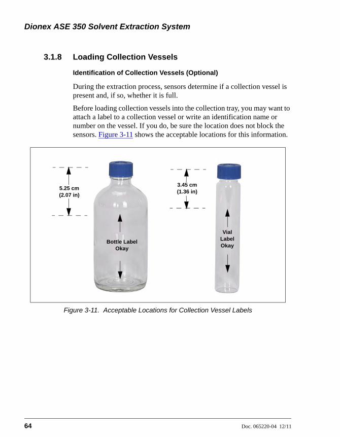
Dionex ASE 350 Solvent Extraction System
64 Doc. 065220-04 12/11
3.1.8 Loading Collection Vessels
Identification of Collection Vessels (Optional)
During the extraction process, sensors determine if a collection vessel is present and, if so, whether it is full.
Before loading collection vessels into the collection tray, you may want to attach a label to a collection vessel or write an identification name or number on the vessel. If you do, be sure the location does not block the sensors. Figure 3-11 shows the acceptable locations for this information.
Figure 3-11. Acceptable Locations for Collection Vessel Labels
5.25 cm (2.07 in)
3.45 cm (1.36 in)
Bottle Label Okay
Vial Label Okay
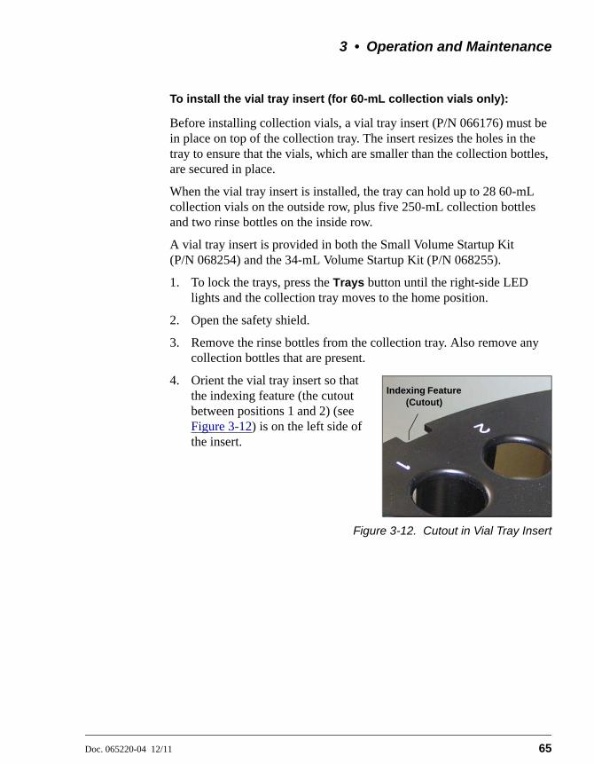
3 • Operation and Maintenance
Doc. 065220-04 12/11 65
To install the vial tray insert (for 60-mL collection vials only):
Before installing collection vials, a vial tray insert (P/N 066176) must be in place on top of the collection tray. The insert resizes the holes in the tray to ensure that the vials, which are smaller than the collection bottles, are secured in place.
When the vial tray insert is installed, the tray can hold up to 28 60-mL collection vials on the outside row, plus five 250-mL collection bottles and two rinse bottles on the inside row.
A vial tray insert is provided in both the Small Volume Startup Kit (P/N 068254) and the 34-mL Volume Startup Kit (P/N 068255).
1. To lock the trays, press the Trays button until the right-side LED lights and the collection tray moves to the home position.
2. Open the safety shield.
3. Remove the rinse bottles from the collection tray. Also remove any collection bottles that are present.
4. Orient the vial tray insert so that the indexing feature (the cutout between positions 1 and 2) (see Figure 3-12) is on the left side of the insert.
Figure 3-12. Cutout in Vial Tray Insert
Indexing Feature (Cutout)

Dionex ASE 350 Solvent Extraction System
66 Doc. 065220-04 12/11
5. Move the vial tray insert inside the safety shield. Hold the tray insert straight over the collection tray.
6. Check that the cutout in the vial tray insert is aligned with the sensor cover on the inside wall (see Figure 3-13). Then, lower the tray insert onto the collection tray and firmly press it into place.
Figure 3-13. Cutout-Sensor Cover Alignment
7. Reinstall the rinse bottles.
8. Load the collection vessels (for instructions, see page 67).
9. After loading the collection vessels:
a. Close the safety shield.
b. Press the Trays button twice. This allows the Dionex ASE 350 to recognize that the vial tray insert has been installed.
SensorCover
Waste Bottle Holder

3 • Operation and Maintenance
Doc. 065220-04 12/11 67
To load the collection vessels:
The collection tray can hold up to 14 collection bottles on the outside row, plus five collection bottles and two rinse bottles on the inside row.
• When running under method control: For each sample cell loaded, load a collection vessel into the collection tray. All collection vessels must be either bottles or vials.
• When running under sequence control: If a vial tray insert is installed (see page 65), you can mix collection bottles and vials in the same run.
• Make sure the collection vessels are large enough for the cell used:
• Load a collection bottle into both rinse positions (labeled R1 and R2).
• When you finish loading collection vessels, close the safety shield.
Before each run, carefully inspect all collection vessels for chips,scratches, or cracks. If a collection vessel shows any sign of damage,do not use it. Use each collection vessel once only.
La présence de fêlure ou d’égratignures sur les flacons de collectedoit être vérifiée avant chaque extraction. N’utilisez jamais un flaconendommagé. Les flacons non gradués sont à usage unique.
Untersuchen Sie vor jedem Lauf alle Sammelgefäße aufAbplatzungen, Kratzer oder Risse. Wenn ein Sammelgefäß eineBeschädigung aufweist, sollten Sie es nicht mehr verwenden.Verwenden Sie nicht graduierte Sammelgefäß nur ein Mal.
Use each collection vessel cap and septum once only. This preventssolvent leaks caused by piercing the septum multiple times.
If the sample cell is: Load this collection vessel:
1 mL, 5 mL, 10 mL, 22 mL, or 34 mL
250-mL bottle or 60-mL vial
66 mL or 100 mL 250-mL bottle only
Check the rinse bottles after each series of runs; if necessary, emptythe bottles before starting the next series.
Dionex ASE 350 Solvent Extraction System
68 Doc. 065220-04 12/11
• If you have just installed the vial tray insert (see page 65), press the Trays button twice. This allows the Dionex ASE 350 to recognize that the vial tray insert has been installed.
3.1.9 Rinsing/Priming the System
Pressing the Rinse button on the keypad starts up to nine manual rinse (or prime) cycles. During a rinse cycle, the cell tray rotates to the nearest rinse tube, the collection tray rotates to a rinse position, and solvent is pumped through the system. This is followed by a 20-second nitrogen purge step.
Run a rinse cycle at the following times:
• After initial setup
• After the Dionex ASE 350 has been shut down for more than one day
• After refilling a solvent reservoir (rinse twice to clear the solvent line of air)
• After changing solvents (rinse twice to remove all of the previous solvent)
To select parameters for a manual rinse:
1. Press Menu to display the MAIN MENU OF SCREENS and press 5 to display the SYSTEM SETUP screen (see Figure 3-14).

3 • Operation and Maintenance
Doc. 065220-04 12/11 69
NOTE For a description of all the parameters on theSYSTEM SETUP screen, see Section B.14.
2. Move the cursor to the RINSE VOLUME field. Press a numeric button to specify the solvent volume to be pumped through the system during each rinse cycle. Press Enter or a cursor arrow button.
3. Move the cursor to the CYCLES field. Press a numeric button to specify the number of rinse cycles to run. Press Enter or a cursor arrow button.
NOTE You can also start a manual rinse cycle from theDionex ASE 350 ePanel in Chromeleon. Fordetails, refer to the Chromeleon Help (under“Controlling a Dionex ASE 350”).
Figure 3-14. System Setup Screen
SYSTEM SETUP
RINSE VOLUME: 5 mL
PRESS UNITS: PSISOUND -- INPUT: NO ERROR: NO
LEAK ABORT: NO
PURGE VALVE: NO
MODE: LOCAL
PREHEAT: 0 MINCYCLES: 1
METHOD RINSE: NO
BYPASS HEATUP: NO
Help prompt

Dionex ASE 350 Solvent Extraction System
70 Doc. 065220-04 12/11
3.1.10 Automatic Rinsing Between Samples
The Dionex ASE 350 can be set up to perform an automatic rinse between sample extractions. The automatic rinse is identical to the manual rinse cycle (see Section 3.1.9), except that the system can be rinsed only once.
• When running under method control, you can set up the Dionex ASE 350 to automatically rinse the system after each sample extraction (see the steps below).
• When running under sequence control, you must specify on each line in the sequence whether an automatic rinse will be performed (see Section 3.2.3).
To set up an automatic rinse during method control:
1. Verify that the rinse tubes are in place. Verify that empty rinse bottles are in place.
2. Press Menu to display the MAIN MENU OF SCREENS and press 5 to display the SYSTEM SETUP screen (see Figure 3-15).
3. Move the cursor to the METHOD RINSE field and press a Select button to toggle the field to YES. Press Enter or a cursor arrow button.
4. Move the cursor to the RINSE VOLUME field. Press a numeric button to specify the solvent volume pumped through the system during the rinse. Press Enter or a cursor arrow button.
Figure 3-15. System Setup Screen
SYSTEM SETUP
RINSE VOLUME: 5 mL
PRESS UNITS: PSISOUND -- INPUT: NO ERROR: NO
LEAK ABORT: NO
PURGE VALVE: NO
MODE: LOCAL
PREHEAT: 0 MINCYCLES: 1
METHOD RINSE: YES
BYPASS HEATUP: NO
Help prompt
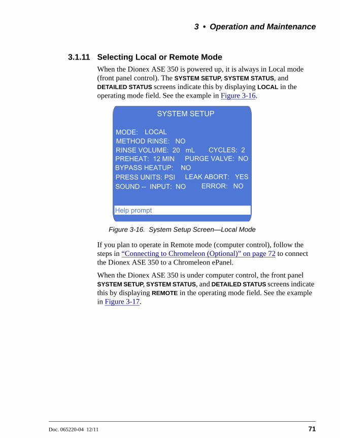
3 • Operation and Maintenance
Doc. 065220-04 12/11 71
3.1.11 Selecting Local or Remote Mode
When the Dionex ASE 350 is powered up, it is always in Local mode (front panel control). The SYSTEM SETUP, SYSTEM STATUS, and DETAILED STATUS screens indicate this by displaying LOCAL in the operating mode field. See the example in Figure 3-16.
If you plan to operate in Remote mode (computer control), follow the steps in “Connecting to Chromeleon (Optional)” on page 72 to connect the Dionex ASE 350 to a Chromeleon ePanel.
When the Dionex ASE 350 is under computer control, the front panel SYSTEM SETUP, SYSTEM STATUS, and DETAILED STATUS screens indicate this by displaying REMOTE in the operating mode field. See the example in Figure 3-17.
Figure 3-16. System Setup Screen—Local Mode
SYSTEM SETUP
RINSE VOLUME: 20 mL
PRESS UNITS: PSISOUND -- INPUT: NO ERROR: NO
LEAK ABORT: YES
PURGE VALVE: NO
MODE: LOCAL
PREHEAT: 12 MINCYCLES: 2
METHOD RINSE: NO
BYPASS HEATUP: NO
Help prompt

Dionex ASE 350 Solvent Extraction System
72 Doc. 065220-04 12/11
To return the Dionex ASE 350 to Local mode, click the Connected button on the ePanel to disconnect the system from Chromeleon (see Figure 3-18) or turn off the Dionex ASE 350 power briefly.
Connecting to Chromeleon (Optional)
1. Start the computer, if it is not already on.
2. Check the Chromeleon Services Manager icon in the notification area of the Windows taskbar and start the service, if necessary:
• If the icon is gray , the Instrument Controller Service is running (idle).
• If the icon is crossed out in red , the Instrument Controller Service is not running. Right-click the icon and click Start Chromeleon Instrument Controller. The icon changes to gold
to indicate that the Instrument Controller Service is starting.
• If the icon is not on the taskbar, click Start on the Windows taskbar and then click All Programs > Chromeleon > Services Manager to open the Services Manager and click Start Instrument Controller.
3. To start the Chromeleon client, click Start > All Programs > Chromeleon 7 > Chromeleon 7.
Figure 3-17. System Status Screen—Remote Mode
SYSTEM SETUP
RINSE VOLUME: 20 mL
PRESS UNITS: PSISOUND -- INPUT: NO ERROR: NO
LEAK ABORT: YES
PURGE VALVE: NO
MODE: REMOTE
PREHEAT: 12 MINCYCLES: 2
METHOD RINSE: NO
BYPASS HEATUP: NO
Help prompt

3 • Operation and Maintenance
Doc. 065220-04 12/11 73
4. To display the Dionex ASE 350 ePanel, click the Instruments category bar in the Console. Click your instrument in the Navigation Pane.
Chromeleon connects to the instrument and displays the Dionex ASE 350 ePanel (see Figure 3-18).
5. Verify that a green button labeled Connected is displayed in the lower left corner of the Dionex ASE 350 graphic. If a red button labeled Disconnected is currently displayed, click the button to connect the Dionex ASE 350 to Chromeleon.
Figure 3-18. Example Chromeleon Dionex ASE 350 ePanel

Dionex ASE 350 Solvent Extraction System
74 Doc. 065220-04 12/11
3.2 Methods and Sequences
NOTES
• This section describes how to create custom methods and sequences from the Dionex ASE 350 front panel. If you prefer to start operation without creating a new method, run the default method(see Section 3.5.1).
• Most of the information here (including descriptions of method and sequence parameters, guidelines for selecting solvent types, and details about solvent saver modes) applies to all Dionex ASE 350 methods and sequences. Therefore, it is advisable to review this section even if you plan to use Chromeleon to create methods and sequences (see Section 3.3).
Each sample extraction occurs according to a predefined set of operating parameters called a method. A method specifies the cell heating time, oven temperature, etc. The Dionex ASE 350 can store up to 24 methods.
When running a series of extractions, you can run each sample using the same method (method control) or customize the series by defining a sequence of runs (sequence control). A sequence specifies the method to run on each sample in the sequence, the sample cell assigned to each collection vessel, and the rinse status after each sample run. The Dionex ASE 350 can store up to 24 sequences.
Table 3-2 summarizes methods and sequences and the control modes.
Feature Description
Method Defines the operating parameters for a single run, including oven temperature, time, amount of solvent rinse, nitrogen purge time, solvent saver mode, cell type, and (when more than one solvent reservoir is installed), solvent types and ratios.
Sequence Defines parameters for a series of runs (cell sequence, method to run on each cell, and rinse status).
Method control Runs the same method on each sample loaded in the tray. By default, a method begins running at collection vessel 1 and cell 1 and continues until completing the entire tray, if it is full, or until reaching an empty collection vessel or cell slot. All collection vessels must be the same type (bottles or vials). Select the method to run on the LOAD METHOD/SEQUENCE screen (see Figure 3-31).
Table 3-2. Methods and Sequences Summary
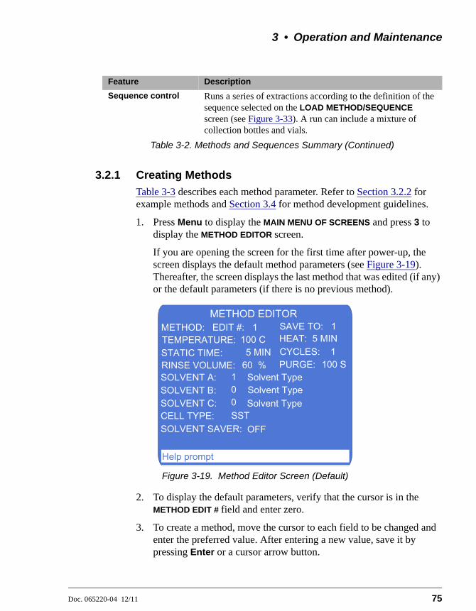
3 • Operation and Maintenance
Doc. 065220-04 12/11 75
3.2.1 Creating Methods
Table 3-3 describes each method parameter. Refer to Section 3.2.2 for example methods and Section 3.4 for method development guidelines.
1. Press Menu to display the MAIN MENU OF SCREENS and press 3 to display the METHOD EDITOR screen.
If you are opening the screen for the first time after power-up, the screen displays the default method parameters (see Figure 3-19). Thereafter, the screen displays the last method that was edited (if any) or the default parameters (if there is no previous method).
2. To display the default parameters, verify that the cursor is in the METHOD EDIT # field and enter zero.
3. To create a method, move the cursor to each field to be changed and enter the preferred value. After entering a new value, save it by pressing Enter or a cursor arrow button.
Sequence control Runs a series of extractions according to the definition of the sequence selected on the LOAD METHOD/SEQUENCE screen (see Figure 3-33). A run can include a mixture of collection bottles and vials.
Figure 3-19. Method Editor Screen (Default)
Feature Description
Table 3-2. Methods and Sequences Summary (Continued)
METHOD EDITOR
STATIC TIME:
SOLVENT B:
CELL TYPE:
RINSE VOLUME:
SOLVENT C:
SOLVENT SAVER:
Solvent TypeSolvent Type
SSTOFF
Solvent Type
EDIT #: 1100 C
5 MIN100 S
1 0 0
SAVE TO: 1
CYCLES: 1
METHOD:
PURGE:
HEAT: 5 MINTEMPERATURE:
SOLVENT A:60 %
Help prompt

Dionex ASE 350 Solvent Extraction System
76 Doc. 065220-04 12/11
NOTE If you make an invalid selection, an errormessage appears. Press any key to erase theerror message, and then correct the entry.
4. After saving the method parameters, move the cursor to the METHOD
SAVE TO field. Enter a new (unused) method number, or press Select to display the next unused method number. For example, if methods 1 and 3 already exist, pressing Select displays 2, the next unused number. Press Enter to save the method under the desired number.
.
Parameter Function Value Range
METHOD EDIT # The number of the method to edit. Enter the number on the numeric keypad or press a Select button to step through the numbers of all existing methods. To display the default method values, press zero.
0, 1 through 24 (default=1)
METHOD SAVE TO
The method that your editing changes will be saved to. Enter the number on the numeric keypad or press a Select button to step through all unused method numbers.
1 through 24(default=1)
TEMPERATURE The temperature set point (the temperature at which the cell is heated). This value determines the duration of the initial heat-up step.Note: Do not select a set point of zero unless you plan to operate at room temperature.
0, 40 to 200 °C (0=off, default=100)
HEAT (read-only)
The time allowed for the sample to reach thermal equilibrium. The duration of the initial heat-up step depends on the temperature set point for the method.Set Point (°C) Heat-up Time (Minutes) 0 (off) 0 40 to 100 5 101 to 125 6 126 to 150 7 151 to 175 8 176 to 200 9
Determined by set point temperature (default=5 min)
STATIC TIME The duration of the static solvent extraction phase.
0 to 2000 min (default=5)
Table 3-3. Method Editor Parameters
3 • Operation and Maintenance
Doc. 065220-04 12/11 77
CYCLES The number of times the STATIC TIME and RINSE VOLUME steps are performed. When more than one cycle is specified, the RINSE VOLUME is divided by the number of cycles for each rinse step (see Example Method 1 on page 82).
1 to 9 (default=1)
RINSE VOLUME The amount of solvent flushed through the sample cell after the STATIC TIME step, expressed as a percentage of the cell volume. For example, if the RINSE VOLUME is 50%, 0.5 mL is flushed through a 1-mL cell, 2.5 mL is flushed through a 5-mL cell, and so on.
0 to 150% vol in 5%increments(default=60)
PURGE The amount of time the cell is purged with nitrogen gas. Thermo Fisher Scientific recommends these settings:
• 20 to 60 seconds for a 1-mL or 5-mL cell
• 40 to 80 (or 90) seconds for a 10-mL or 22-mL cell
• 70 to 110 seconds for a 34-mL cell
• 160 to 200 seconds for a 66-mL cell
• 250 to 290 seconds for a 100-mL cell
20 to 900 sec (default=100)
SOLVENTA, B, C
The solvent ratio and type.
• When more than one solvent reservoir is installed, program the mixture of solvents in ratios. For example, to obtain a mix containing one-sixth solvent A, one-third solvent B, and one-half solvent C, enter ratios of 1, 2, and 3 for solvents A, B, and C, respectively.
• Solvent types are listed on page 79.
0 to 5 (default= SOLVENT A, 1; SOLVENT B, 0; SOLVENT C, 0)
CELL TYPE The cell type: SST (stainless steel) or Zr (zirconium).
SST (default) Zr
Parameter Function Value Range
Table 3-3. Method Editor Parameters (Continued)

Dionex ASE 350 Solvent Extraction System
78 Doc. 065220-04 12/11
Notes on Solvent Saver Mode
• Selecting solvent saver pressure or flow mode automatically resets the RINSE VOLUME field to zero and the CYCLES field to 1. You can change the rinse volume, but not the number of cycles.
• When solvent saver flow mode is selected, the cell size determines the flow rate range (see the table on the next page). If a change to the CELL SIZE field means that the previously selected flow rate is too high, the flow rate is automatically reset to the maximum flow rate for the new cell size. Conversely, if the previously selected flow rate is too low, the flow rate is reset to the lowest flow rate for the new cell size.
CELL SIZE The cell size. This field is displayed only when solvent saver flow mode is selected.The cell size determines the flow rate range; for details, see “Notes on Solvent Saver Mode” on page 78.
1, 5, 10, 22, 34, 66, or 100 mL (SST cells); 66 or 100 mL (Zr cells)
SOLVENT SAVER
Selects the solvent saver mode (or turns it off). There are two options:
• Select PRESS (the pressure mode) to maintain a fixed cell pressure and minimize solvent usage by eliminating the introduction of fresh solvent during the heating and static cycles.
• Select FLOW (the flow mode) to have small aliquots of solvent delivered to the cell at the specified flow rate throughout the static step.
OFF (default) PRESS, FLOW
FLOW Selects the solvent flow rate (in increments of 0.5 mL). This field is displayed only when solvent saver flow mode is selected. The flow rate range is determined by the cell size; for details, see “Notes on Solvent Saver Mode” on page 78.
1.0 to 5.0 mL/min (default=1)
Parameter Function Value Range
Table 3-3. Method Editor Parameters (Continued)

3 • Operation and Maintenance
Doc. 065220-04 12/11 79
• When solvent saver flow mode is selected, the default flow rate is 1.0 mL/min. If you turn off solvent saver mode (or switch to pressure mode), the FLOW field is no longer displayed.
• When solvent saver pressure mode is selected (or solvent saver mode is off), the CELL SIZE and FLOW fields are not displayed. Switching to flow mode automatically displays these fields and resets them as follows: The CELL SIZE field will display the value last selected (if any); if there is no previous selection, the field will display 34 mL. The FLOW field will display the default value of 1.0 mL/min.
Entering Solvent Types and Ratios
The METHOD EDITOR screen lists some of the most common solvents for extractions. From the list, select the type(s) and ratio of solvent(s) used in each method. If the solvent you plan to use is not listed, accept the default setting: Solvent Type.
When more than one solvent reservoir is installed, these selections determine the solvent type and amount delivered to the Dionex ASE 350. If only one reservoir is installed, enter 1 for that solvent; enter zero for the other solvents.
Cell Size Flow Rate Range
1 mL, 5 mL 0.5 to 2.0 mL/min
10 mL, 22 mL 1.0 to 2.0 mL/min
34 mL 1.0 to 3.0 mL/min
66 mL 1.0 to 4.0 mL/min
100 mL 1.0 to 5.0 mL/min
Do not use solvents with an autoignition point below 200 °C. If there isa question about solvent suitability, contact Thermo Fisher Scientific.
N'utilisez pas de solvants ayant un point éclair inférieur à 200 °C. Letableau ci-dessous liste quelques solvants qui ne doivent pas êtreutilisés avec l'Dionex ASE 350. Contactez Thermo Fisher Scientific sivous avez un doute concernant l’usage d’un solvant absent de la liste.

Dionex ASE 350 Solvent Extraction System
80 Doc. 065220-04 12/11
To select a solvent type:
1. Move the cursor to the SOLVENT field and press Select or Select to scroll through a list of solvents that can be used with the Dionex ASE 350. These are the solvent options:
2. After selecting the solvent type, press the left cursor arrow to go to the RATIO field for the installed solvent and enter a value from 0 to 5.
3. If more than one solvent will be used, enter the solvent type and ratio in each additional RATIO field.
Each solvent will be mixed according to the ratio of the number entered for that solvent divided by the sum of numbers entered for all solvents. For example:
• If you enter a ratio of 1 for all three solvents, the result is a mix containing one-third each of solvents A, B, and C.
• If you enter ratios of 1, 2, and 3 for solvents A, B, and C, respectively, the result is a mix that is one-sixth solvent A, one-third solvent B, and one-half solvent C.
NOTE If you enter a ratio of 0 for all three solvents, theDionex ASE 350 will override these selectionsand the default setting (SOLVENT A and a ratioof 1) will remain in effect.
Verwenden Sie keine Lösungsmittel, derenSelbstentzündungstemperatur unter 200 °C liegt. Bei Fragen zurEignung von Lösungsmitteln wenden Sie sich bitte an Thermo FisherScientific.
Acetone Hexane MeCl2 Toluene
Acetonitrile iso-Octane Pet Ether Water
Chloroform iso-Propanol PERC Water/Acid
Ethanol Methanol THF Water/Base

3 • Operation and Maintenance
Doc. 065220-04 12/11 81
Editing Methods
After creating a method, you can modify it by changing parameter values. When you finish, you can either save the changes to the existing method number or save the altered method to a new method number and preserve the original method.
1. Press Menu to display the MAIN MENU OF SCREENS and press 3 to display the METHOD EDITOR screen.
2. In the METHOD EDIT # field, enter the number of the method to be edited (1 through 24), or press a Select button to scroll through the numbers of previously stored methods.
To display the default method parameters, enter zero.
3. After selecting the method number, press Enter. The method’s defined parameters appear.
4. To change a parameter value, move the cursor to the field and enter the new value. This deletes the previous value. Table 3-3 lists the values allowed for each parameter.
5. When changes are complete, move the cursor to the METHOD SAVE
TO field. Press Enter to save the changes to the current method number, or select a new method number and press Enter.

Dionex ASE 350 Solvent Extraction System
82 Doc. 065220-04 12/11
3.2.2 Example Methods
Example Method 1: Standard Extraction Mode
Figure 3-20 illustrates the METHOD EDITOR screen for Example 1.
• When you load the method (or a sequence using this method), the oven begins heating to 75 °C.
• To start the run, press Start any time after the method (or sequence) is loaded.
• The collection vessel is loaded.
• When the oven reaches the set point, the cell is moved into the oven and the pump fills the cell with solvent A. The static valve remains closed, and the pump continues pumping until the pressure reaches 10.34 MPa (1500 psi).
• The initial fill step and 5-minute heat step occur, followed by the first 5-minute static step.
• After the static step, the static valve opens and the pump rinses 13% of the cell volume of fresh solvent through the cell. This amount is approximately one-third of the total of 40% to be rinsed through in the three cycles.
• The static and cell rinse cycles repeat two more times.
Figure 3-20. Example Method 1: Standard Mode
METHOD EDITOR
STATIC TIME:
SOLVENT B:
CELL TYPE:
RINSE VOLUME:
SOLVENT C:
SOLVENT SAVER:
MethanolSolvent Type
SST OFF
Solvent Type
EDIT #: 75 C
5 MIN 90 S
1 0 0
SAVE TO: 3
CYCLES: 3
METHOD:
PURGE:
HEAT: 5 MINTEMPERATURE:
SOLVENT A: 40 %
Help prompt

3 • Operation and Maintenance
Doc. 065220-04 12/11 83
• The method ends with a 90-second nitrogen purge step.
To create Example Method 1:
1. Press Menu to display the MAIN MENU OF SCREENS and press 3 to display the METHOD EDITOR screen.
2. With the cursor positioned in the METHOD EDIT field, enter zero to display the default method parameters.
3. Move the cursor to the following fields and enter the given values:
4. Move the cursor to the SAVE TO field and enter 3 for the new method. Press Enter.
TEMPERATURE 75 °C
CYCLES 3
RINSE VOLUME 40%
PURGE 90 S
SOLVENT A 1
Solvent Type Methanol

Dionex ASE 350 Solvent Extraction System
84 Doc. 065220-04 12/11
Example Method 2: Standard Extraction Mode
Figure 3-21 illustrates the METHOD EDITOR screen for Example 2.
• When you load the method (or a sequence using this method), the oven begins heating to 125 °C.
• To start the run, press Start any time after the method (or sequence) is loaded.
• The collection vessel is loaded.
• When the oven reaches the set point, the cell is moved into the oven and the pump fills the cell with equal parts of solvents A and B. The static valve closes and the pump continues pumping until the pressure reaches 10.34 MPa (1500 psi).
• The initial 6-minute heat step occurs, followed by a 10-minute static step.
• After the static step, the static valve opens and the pump rinses 70% of the cell volume of fresh solvent through the cell.
• The method ends with a 160-second nitrogen purge step.
Figure 3-21. Example Method 2: Standard Mode
METHOD EDITOR
STATIC TIME:
SOLVENT B:
CELL TYPE:
RINSE VOLUME:
SOLVENT C:
SOLVENT SAVER:
AcetoneHexane
SSTOFF
Solvent Type
EDIT #: 125 C
10 MIN160 S
1 1 0
SAVE TO: 2
CYCLES: 1
METHOD:
PURGE:
HEAT: 6 MINTEMPERATURE:
SOLVENT A:70 %
Help prompt

3 • Operation and Maintenance
Doc. 065220-04 12/11 85
Example Method 3: Solvent Saver Pressure Mode
Figure 3-22 illustrates the METHOD EDITOR screen for Example 3.
• When you load the method (or a sequence using this method), the oven begins heating to 125 °C.
• To start the run, press Start any time after the method (or sequence) is loaded.
• The collection vessel is loaded.
• When the oven reaches the set point, the cell is moved into the oven. The pump begins filling the cell with solvent at the full flow rate (as in standard mode). When the pressure reaches 10.34 MPa (1500 psi), the pump is turned off.
• The initial 6-minute heat step occurs, followed by a 15-minute static step.
• After the static step, the static valve opens.
• The method ends with a 120-second nitrogen purge step.
Figure 3-22. Example Method 3: Pressure Mode
METHOD EDITOR
STATIC TIME:
SOLVENT B:
CELL TYPE:
RINSE VOLUME:
SOLVENT C:
SOLVENT SAVER:
HexaneAcetone
SSTPRESS
Solvent Type
EDIT #: 125 C
15 MIN120 S
4 1 0
SAVE TO: 1
CYCLES: 1
METHOD:
PURGE:
HEAT: 6 MINTEMPERATURE:
SOLVENT A: 0 %
Help prompt

Dionex ASE 350 Solvent Extraction System
86 Doc. 065220-04 12/11
Example Method 4: Solvent Saver Flow Mode
Figure 3-23 illustrates the METHOD EDITOR screen for Example 4.
• When you load the method (or a sequence using this method), the oven begins heating to 100 °C.
• To start the run, press Start any time after the method (or sequence) is loaded.
• The collection vessel is loaded.
• When the oven reaches the set point, the cell is moved into the oven. The pump begins filling the cell with solvent at the full flow rate (as in standard mode). When the pressure reaches 10.34 MPa (1500 psi), the pump is turned off.
• The initial 5-minute heat step begins. When the pressure reaches 11.72 MPa (1700 psi), the static valve opens to release some solvent.
• This is followed by a 5-minute static step. During the static step, the static valve opens at 9.65 MPa (1400 psi) and the pump delivers flow at 1.0 mL/min.
• After the static step, the static valve opens.
• The method ends with a 120-second nitrogen purge step.
Figure 3-23. Example Method 4: Flow Mode
METHOD EDITOR
STATIC TIME:
SOLVENT B:
CELL TYPE:
RINSE VOLUME:
SOLVENT C:
SOLVENT SAVER:
HexaneSolvent Type
SIZE: 341.0
SSTFLOW
Solvent Type
FLOW:
EDIT #:100 C
5 MIN120 S
1 0 0
SAVE TO: 1
CYCLES: 1
METHOD:
PURGE:
HEAT: 5 MINTEMPERATURE:
SOLVENT A: 0 %
Help prompt
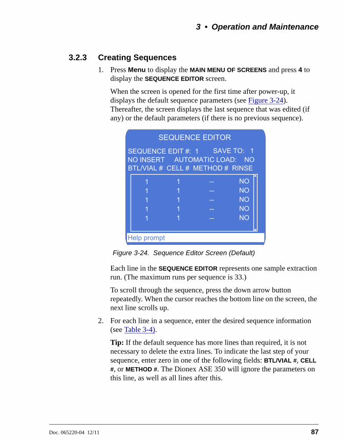
3 • Operation and Maintenance
Doc. 065220-04 12/11 87
3.2.3 Creating Sequences
1. Press Menu to display the MAIN MENU OF SCREENS and press 4 to display the SEQUENCE EDITOR screen.
When the screen is opened for the first time after power-up, it displays the default sequence parameters (see Figure 3-24). Thereafter, the screen displays the last sequence that was edited (if any) or the default parameters (if there is no previous sequence).
Each line in the SEQUENCE EDITOR represents one sample extraction run. (The maximum runs per sequence is 33.)
To scroll through the sequence, press the down arrow button repeatedly. When the cursor reaches the bottom line on the screen, the next line scrolls up.
2. For each line in a sequence, enter the desired sequence information (see Table 3-4).
Tip: If the default sequence has more lines than required, it is not necessary to delete the extra lines. To indicate the last step of your sequence, enter zero in one of the following fields: BTL/VIAL #, CELL
#, or METHOD #. The Dionex ASE 350 will ignore the parameters on this line, as well as all lines after this.
Figure 3-24. Sequence Editor Screen (Default)
SEQUENCE EDITOR
AUTOMATIC LOAD: NOSAVE TO: 1SEQUENCE EDIT #: 1
NO INSERTBTL/VIAL # CELL # METHOD # RINSE
11111
11111
----------
NONONONONO
Help prompt
Dionex ASE 350 Solvent Extraction System
88 Doc. 065220-04 12/11
3. Move the cursor to the SEQUENCE SAVE TO field. Enter a number for the new sequence (1 through 24), or press Select to display the next unused sequence number and press Enter to save.
Sequence Field Description Values
SEQUENCE EDIT #
The number of the sequence to edit. Enter the number on the numeric keypad or press a Select button to step through the numbers of all existing sequences. To display the default sequence values, press zero.
0, 1 through 24 (default=1)
SEQUENCE SAVE TO
The sequence number that your editing changes will be saved to. Enter the number on the numeric keypad or press a Select button to step through all of the unused sequence numbers.
1 through 24 (default=1)
NO INSERT Indicates whether a vial tray insert (P/N 066176) is installed. The insert is required to accommodate collection vials; for details, see page 65.
NO INSERT, INSERT (default=NO INSERT)
AUTOMATIC LOAD
Selecting YES automatically loads the sequence currently displayed and turns on the top plate and oven heaters. To immediately run the sequence, press Start.This feature eliminates the need to exit the SEQUENCE EDITOR and load the sequence from the LOAD METHOD/SEQUENCE screen (see Section 3.5.2).
YES=Load sequence, NO=Do not load sequence
BTL/VIAL # The number of the collection bottle or vial to be used.Any line in the sequence that includes a zero in the BTL/VIAL # field is defined as the last line of the sequence. The Dionex ASE 350 will ignore any parameters on this line, as well as all lines after this.
No vial tray insert: 1–19 (bottles only) With a vial tray insert: 1–28 for vials; 29–33 for bottles (default=1)
Table 3-4. Sequence Editor Parameters

3 • Operation and Maintenance
Doc. 065220-04 12/11 89
CELL # The sample cell used for the run. You can use the default (cell 1) or enter a different cell number. For example, when performing multiple extractions on the same sample, you can assign one sample cell to multiple collection vessels (see Example Sequence 3 on page 94).Any line in the sequence that includes a zero in the CELL # field is defined as the last line of the sequence. The Dionex ASE 350 will ignore any parameters on this line, as well as all lines after this.
1 through 24 (default=1)
METHOD # The number of the method to run. If desired, a different method can be run on each sample.Thermo Fisher Scientific recommends entering methods in a sequence from coolest to hottest. Because the oven heats up faster than it cools down, this will minimize the oven wait time between methods.Any line in the sequence that includes a zero in the METHOD # field is defined as the last line of the sequence. The Dionex ASE 350 will ignore any parameters on this line, as well as all lines after this.
1 through 24 (default= --)
Sequence Field Description Values
Table 3-4. Sequence Editor Parameters (Continued)
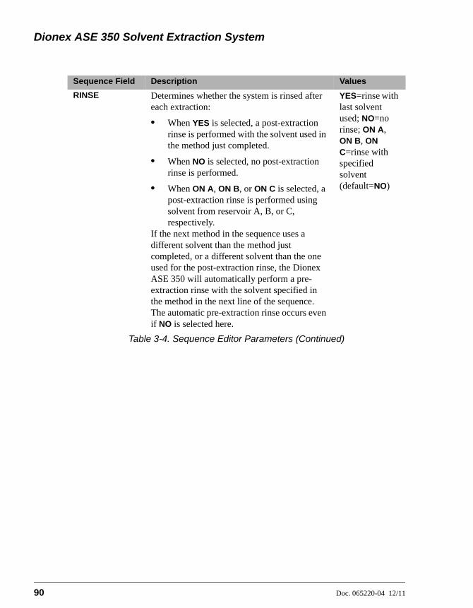
Dionex ASE 350 Solvent Extraction System
90 Doc. 065220-04 12/11
RINSE Determines whether the system is rinsed after each extraction:
• When YES is selected, a post-extraction rinse is performed with the solvent used in the method just completed.
• When NO is selected, no post-extraction rinse is performed.
• When ON A, ON B, or ON C is selected, a post-extraction rinse is performed using solvent from reservoir A, B, or C, respectively.
If the next method in the sequence uses a different solvent than the method just completed, or a different solvent than the one used for the post-extraction rinse, the Dionex ASE 350 will automatically perform a pre-extraction rinse with the solvent specified in the method in the next line of the sequence. The automatic pre-extraction rinse occurs even if NO is selected here.
YES=rinse with last solvent used; NO=no rinse; ON A, ON B, ON C=rinse with specified solvent (default=NO)
Sequence Field Description Values
Table 3-4. Sequence Editor Parameters (Continued)
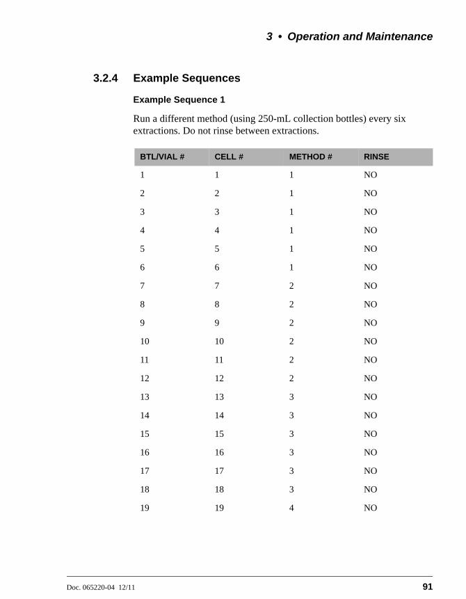
3 • Operation and Maintenance
Doc. 065220-04 12/11 91
3.2.4 Example Sequences
Example Sequence 1
Run a different method (using 250-mL collection bottles) every six extractions. Do not rinse between extractions.
BTL/VIAL # CELL # METHOD # RINSE
1 1 1 NO
2 2 1 NO
3 3 1 NO
4 4 1 NO
5 5 1 NO
6 6 1 NO
7 7 2 NO
8 8 2 NO
9 9 2 NO
10 10 2 NO
11 11 2 NO
12 12 2 NO
13 13 3 NO
14 14 3 NO
15 15 3 NO
16 16 3 NO
17 17 3 NO
18 18 3 NO
19 19 4 NO

Dionex ASE 350 Solvent Extraction System
92 Doc. 065220-04 12/11
To create Example Sequence 1:
1. Press Menu to display the MAIN MENU OF SCREENS and press 5 to display the SYSTEM SETUP screen.
2. Verify that the METHOD RINSE field is NO. If necessary, move the cursor to the field and press Select to toggle to NO. Press Enter.
3. Press Menu to display the MAIN MENU OF SCREENS and press 4 to display the SEQUENCE EDITOR screen.
4. Verify that NO INSERT is displayed on the second line. If necessary, move the cursor to the field and press Select to toggle to NO
INSERT. Press Enter.
5. With the cursor positioned in the SEQUENCE EDIT # field, enter zero to display the default sequence parameters (see Table 3-4).
6. For the first line in the sequence, move the cursor to the METHOD #
field and enter 1. This is the only parameter that needs to be entered here; all other parameters remain at their default values.
NOTE It is not necessary to change the RINSE field onany line of Example Sequence 1.
7. For the second line in the sequence, move the cursor to the following fields and enter the given values:
8. For the third line in the sequence, move the cursor to the following fields and enter the given values:
9. Repeat the steps above until all parameters have been selected. When you finish, move the cursor to the SEQUENCE SAVE TO field and enter a number for the new sequence. Press Enter.
BTL/VIAL # 2
CELL # 2
METHOD # 1
BTL/VIAL # 3
CELL # 3
METHOD # 1
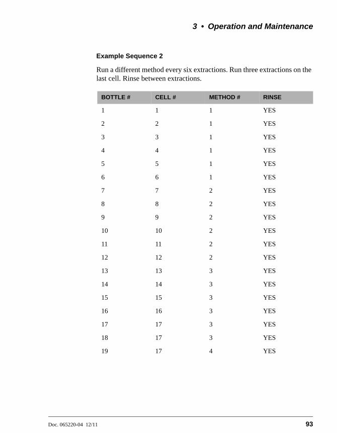
3 • Operation and Maintenance
Doc. 065220-04 12/11 93
Example Sequence 2
Run a different method every six extractions. Run three extractions on the last cell. Rinse between extractions.
BOTTLE # CELL # METHOD # RINSE
1 1 1 YES
2 2 1 YES
3 3 1 YES
4 4 1 YES
5 5 1 YES
6 6 1 YES
7 7 2 YES
8 8 2 YES
9 9 2 YES
10 10 2 YES
11 11 2 YES
12 12 2 YES
13 13 3 YES
14 14 3 YES
15 15 3 YES
16 16 3 YES
17 17 3 YES
18 17 3 YES
19 17 4 YES
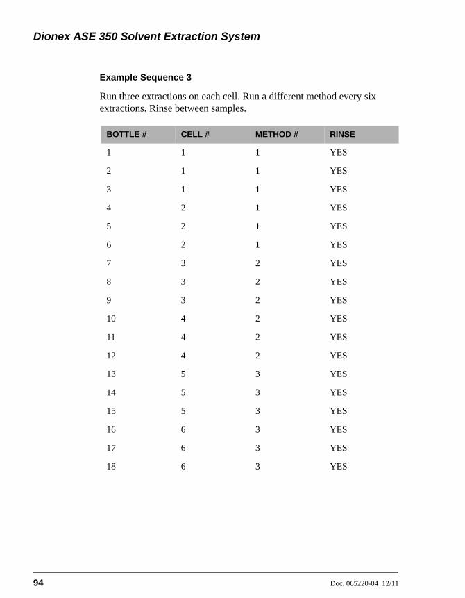
Dionex ASE 350 Solvent Extraction System
94 Doc. 065220-04 12/11
Example Sequence 3
Run three extractions on each cell. Run a different method every six extractions. Rinse between samples.
BOTTLE # CELL # METHOD # RINSE
1 1 1 YES
2 1 1 YES
3 1 1 YES
4 2 1 YES
5 2 1 YES
6 2 1 YES
7 3 2 YES
8 3 2 YES
9 3 2 YES
10 4 2 YES
11 4 2 YES
12 4 2 YES
13 5 3 YES
14 5 3 YES
15 5 3 YES
16 6 3 YES
17 6 3 YES
18 6 3 YES
3 • Operation and Maintenance
Doc. 065220-04 12/11 95
3.3 Methods and Sequences in Chromeleon
NOTES
• This section provides a brief description of the steps required to set up and run the Dionex ASE 350 with Chromeleon. For detailed instructions, refer to the Chromeleon Help.
• Most of the information in Section 3.2 (including descriptions of method and sequence parameters, guidelines for selecting solvent types, and details about solvent saver modes) applies to all Dionex ASE 350 methods and sequences. Therefore, it is advisable to review this information even when using Chromeleon to create methods and sequences.
3.3.1 Overview
1. Create an instrument method that specifies the functions the Dionex ASE 350 should perform. Instrument methods can be created automatically (with the help of the Instrument Method Wizard) or manually (by editing an existing method).
• When a Dionex ASE 350 is configured in Chromeleon, the Instrument Method Wizard includes pages (Rinse Settings and Extraction Method) specifically for the Dionex ASE 350.
• After creating the instrument method, you can specify options related to the preheating and initial heat-up steps on the System Setup page in the Instrument Method Editor.
2. Create a sequence (a list of extractions). For each extraction, specify the starting cell and vial positions and the number of extractions to be performed. You can create sequences automatically (with the help of the Sequence Wizard) or manually (by editing an existing sequence).
NOTE Chromeleon can run up to 456 extractions persequence. In Local mode, the Dionex ASE 350can run up to 33 extractions per sequence.
3. Load the sequence into a queue by clicking Start on the Sequence Control Bar above the extraction list.
• If this is the only sequence in the queue, it will start immediately.

Dionex ASE 350 Solvent Extraction System
96 Doc. 065220-04 12/11
• If the queue already includes one or more sequences, the new sequence will be appended to the queue.
4. When a queue starts, Chromeleon performs a verification procedure called a Ready Check to make sure the instrument is ready for operation and the methods used to run the sequences are error-free. If no problems are found, the following message is displayed: Ready Check result: Successful.
If problems are found, messages describing the problems are displayed. Each message is preceded by an icon that identifies the seriousness of the problem.
NOTE In addition to these automatic checks, you canmanually run a Ready Check. For details, referto the Chromeleon Help.

3 • Operation and Maintenance
Doc. 065220-04 12/11 97
3.3.2 Example Methods
Example Method 5: Solvent Saver Fixed Volume Mode
NOTE Chromeleon control is required to run fixed volumemethods.
Figure 3-25 illustrates the Extraction Method page for Example 5. In this method, the solvent volume is less than the cell volume.
Figure 3-25. Example Method 5: Fixed Volume Mode

Dionex ASE 350 Solvent Extraction System
98 Doc. 065220-04 12/11
• After creating a sequence that contains this method, click Start on the Sequence Control Bar (above the extraction list) to start the run.
• The collection vessel is loaded.
• The oven begins heating to 150 °C.
• When the oven reaches the set point, the cell is moved into the oven. The pump begins filling the cell with solvent A; when 20 mL of solvent A has been delivered, the pump is turned off.
• The extraction proceeds through the remaining fill time, the 5-minute heat step, and the 20-minute static step. Because the solvent volume is less than the cell volume, the pressure will not reach 11.72 MPa (1700 psi) and the static valve will remain closed.
• After the static step, the static valve opens.
• The method ends with a 100-second nitrogen purge step.
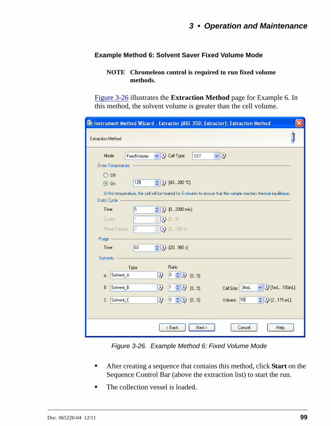
3 • Operation and Maintenance
Doc. 065220-04 12/11 99
Example Method 6: Solvent Saver Fixed Volume Mode
NOTE Chromeleon control is required to run fixed volumemethods.
Figure 3-26 illustrates the Extraction Method page for Example 6. In this method, the solvent volume is greater than the cell volume.
• After creating a sequence that contains this method, click Start on the Sequence Control Bar (above the extraction list) to start the run.
• The collection vessel is loaded.
Figure 3-26. Example Method 6: Fixed Volume Mode
Dionex ASE 350 Solvent Extraction System
100 Doc. 065220-04 12/11
• When the oven reaches the set point, the cell is moved into the oven and the pump fills the cell with solvent B. The static valve remains closed, and the pump continues pumping until the pressure reaches 10.34 MPa (1500 psi).
• The initial fill step and the 6-minute heat step occur, followed by the 5-minute static step.
• After the static step, the static valve opens and the pump continues until it has pumped a total of 50 mL.
• The method ends with a 60-second nitrogen purge step.

3 • Operation and Maintenance
Doc. 065220-04 12/11 101
Example Method 7: Solvent Saver Gradient Mode
NOTE Chromeleon control is required to run gradientmethods.
Figure 3-27 illustrates the Extraction Method page for Example 7. In this method, a mixture of two solvents is delivered.
• After creating a sequence that contains this method, click Start on the Sequence Control Bar (above the extraction list) to start the run.
• The collection vessel is loaded.
Figure 3-27. Example Method 7: Gradient Mode

Dionex ASE 350 Solvent Extraction System
102 Doc. 065220-04 12/11
• When the oven reaches the set point, the cell is moved into the oven and the pump fills the cell with solvent A. The static valve remains closed, and the pump continues pumping until the pressure reaches 10.34 MPa (1500 psi).
• The initial fill step and the 5-minute heat step occur.
• During the static step, the pump delivers 20 mL of solvent (20 minutes× 1.0 mL/min). At the beginning of the static step, the gradient flow consists of 100% solvent A. At 10 minutes into the static step, the pump delivers equal amounts of solvent A and solvent C. At the end of the static step, the pump is delivering solvent C only.
• After the static step, the static valve opens and the pump delivers about 26 mL (40% of the 66-mL cell) of solvent C.
• The method ends with an 80-second nitrogen purge.

3 • Operation and Maintenance
Doc. 065220-04 12/11 103
Example Method 8: Solvent Saver Gradient Mode
NOTE Chromeleon control is required to run gradientmethods.
Figure 3-27 illustrates the Extraction Method page for Example 8. In this method, a mixture of three solvents is delivered.
• After creating a sequence that contains this method, click Start on the Sequence Control Bar (above the extraction list) to start the run.
• The collection vessel is loaded.
Figure 3-28. Example Method 8: Gradient Mode
Dionex ASE 350 Solvent Extraction System
104 Doc. 065220-04 12/11
• When the oven reaches the set point, the cell is moved into the oven and the pump fills the cell with solvents A and B at a ratio of 2:1. The static valve remains closed, and the pump continues pumping until the pressure reaches 10.34 MPa (1500 psi). The initial fill step and the 6-minute heat step occur.
• During the static step, the pump delivers 16 mL of solvent (8 minutes × 2.0 mL/min). At the beginning of the static step, the gradient flow consists of solvents A and B at a ratio of 2:1. At 4 minutes into the static step, the pump delivers equal amounts of solvents A, B, and C at a ratio of 1:1:1. At the end of the static step, the pump is delivering solvents B and C at a ratio of 1:2.
• After the static step, the static valve opens and the pump delivers about 2 mL (20% of the 10-mL cell) of solvents B and C at a ratio of 1:2.
• The method ends with a 30-second nitrogen purge step.

3 • Operation and Maintenance
Doc. 065220-04 12/11 105
3.4 Method Development Guidelines
Follow the procedure below when developing a method for a new sample type.
1. Select a solvent(s) (see Section 3.1.1).
2. Prepare the sample (see Section 3.1.3).
3. Select the cell size (see Section 3.1.4).
For more details about method development, see Appendix E of this manual. You may also want to refer to Thermo Scientific Dionex Technical Notes 208, 209, and 210. Technical Notes are provided on the Thermo Scientific Reference Library DVD (P/N 053891).
4. Create a new method with default operating parameters. To do this, go to the METHOD EDITOR screen, position the cursor in the METHOD EDIT # field, and enter zero to display the default parameters. Move the cursor to the METHOD
SAVE TO field and select a new method number (2, for example). Press Enter to save the method.
5. Create a sequence that extracts the same sample three times into separate collection vessels (see the example in Figure 3-29). Specify the method created in Step 4 for each extraction.
6. Run the sequence and analyze the extracts.
Figure 3-29. Example Sequence for Method Development
SEQUENCE EDITOR
AUTOMATIC LOAD: YESSAVE TO: 2SEQUENCE EDIT #: 2
INSERTBTL/VIAL # CELL # METHOD # RINSE
12345
1110
222
YESYESYESYESYES
Help prompt

Dionex ASE 350 Solvent Extraction System
106 Doc. 065220-04 12/11
7. If target analytes are present in collection vessel 2 or 3, make the following adjustments (one at a time) to the method:
a. Raise the temperature. In general, raising the temperature increases the efficiency of the extraction process. However, because compounds can degrade at high temperatures, it is advisable to raise the temperature in small increments (10 to 20 °C). The maximum allowable temperature of the Dionex ASE 350 is 200 °C. If oxidation is a concern, degas the solvent before use.
b. Run two static cycles. Extending the static time enhances diffusion of the analytes into the extraction fluid. Separating the static time into two cycles, rather than using one longer cycle, allows the introduction of fresh solvent midway through. The fresh solvent helps maintain a favorable solvent/sample equilibrium for samples that are heavily loaded or otherwise difficult to extract.
c. Increase the rinse volume to allow more solvent to pass through the sample. The rinse volume can be up to 150% of the cell volume.
NOTE To prevent overfilling of the 34-mL and 100-mLcells or the collection bottles or vials, it may benecessary to balance the number of static cycles andthe rinse volume.
8. After each adjustment, repeat the sequence and analyze the extract. When target analytes no longer appear in the extract from the second collection vessel, the method is complete for this sample type.
9. If analytes still appear in the extract from the second collection vessel, make the following adjustments (one at a time) to the method:
• Run three static cycles.
• Raise the temperature again.
• Extend the static time.
• Select a different solvent.
When target analytes no longer appear in the extract from the second collection vessel, the method is complete for this sample type.

3 • Operation and Maintenance
Doc. 065220-04 12/11 107
3.5 Operating the Dionex ASE 350
3.5.1 Operating Under Method Control
Before starting a run, decide whether to create a new method that defines operating conditions (see Section 3.2.1) or use the Dionex ASE 350 default method.
The default method lets you get started running quickly, without having to create any custom methods. Before you can run a default method, you must assign a new method number to it (see below).
To renumber the default method:
1. Press Menu to display the MAIN MENU OF SCREENS and press 3 to display the METHOD EDITOR screen.
2. With the cursor in the METHOD EDIT # field, enter zero to display the default parameters (see Figure 3-30).
3. For each solvent selected, check that the corresponding solvent reservoir is installed.
Before beginning a run, check that the door to the service area isclosed. If the door to the service area is open during operation, theoven may not reach and maintain the set temperature.

Dionex ASE 350 Solvent Extraction System
108 Doc. 065220-04 12/11
4. Move the cursor to the METHOD SAVE TO field; press Select to display the next unused method number and press Enter. The new method can now be loaded and run.
To load a method and start the run:
5. Press Menu to display the MAIN MENU OF SCREENS and press 1 to display the LOAD METHOD/SEQUENCE screen (see Figure 3-31).
Figure 3-30. Method Editor Screen (Default)
Figure 3-31. Load Method/Sequence Screen
METHOD EDITOR
STATIC TIME:
SOLVENT B:
CELL TYPE:
RINSE VOLUME:
SOLVENT C:
SOLVENT SAVER:
Solvent TypeSolvent Type
SSTOFF
Solvent Type
EDIT #: 1100 C
5 MIN100 S
1 0 0
SAVE TO: 1
CYCLES: 1
METHOD:
PURGE:
HEAT: 5 MINTEMPERATURE:
SOLVENT A:60 %
Help prompt
LOAD METHOD/SEQUENCE
LOAD: METHOD11
NUMBER:BTL/VIAL #:
Help prompt

3 • Operation and Maintenance
Doc. 065220-04 12/11 109
6. Verify that METHOD appears in the LOAD field. If it does not, press a Select button to toggle to METHOD.
7. Move the cursor to the NUMBER field and enter the number of the method. Press Enter or a cursor arrow.
8. The number selected in the BTL/VIAL # field applies to both the collection vessel and the sample cell. By default, the method begins running at collection vessel 1 and cell 1. To begin the run at a different collection vessel and cell, move the cursor to the BTL/VIAL # field and enter the preferred number. Press Enter.
This closes the LOAD METHOD/SEQUENCE screen and opens the SYSTEM STATUS screen. (If you do not edit the BTL/VIAL # field, you can open the SYSTEM STATUS screen by moving the cursor to the BTL/VIAL # field and pressing Enter.)
The SYSTEM STATUS screen displays the method number, as well as the status of several other Dionex ASE 350 operating parameters (see Figure 3-32).
NOTE The temperature set point is activatedimmediately after the method is loaded (beforeyou press Start). If the current oventemperature is below the set point, the ovenbegins heating.
Figure 3-32. System Status Screen
Help prompt
SYSTEM STATUS
TIME REMAINING:
CELL #:
VOLUME DELIVERED:
TIME STEP:
VIAL #:SIZE:
0 PSI
0.00
- - - - - -
0 mL
100
STATUS: OVEN WAIT
LOCAL
TEMP: SET 40 C ACTUAL 40 C
MET #: 1 SEQ #: 1
PRESSURE:
MODE: STANDARD

Dionex ASE 350 Solvent Extraction System
110 Doc. 065220-04 12/11
9. Press Start to begin the run. If the oven has not reached the set point, there is a delay while the oven heats up or cools down. During this time, the SYSTEM STATUS screen displays OVEN WAIT.
When the oven is within 1 °C of the set point, the cell and collection trays rotate to the first positions and the Dionex ASE 350 begins running the first sample. During method control, the Dionex ASE 350 runs samples sequentially until it reaches an empty cell or collection vessel position or, if the trays are full, until all samples have been run and the trays have returned to positions 1. See Section 2.6 for details about the extraction process.
During a run, the status of operating parameters displayed on the SYSTEM STATUS screen is updated every 1 second.
3.5.2 Operating Under Sequence Control
1. Press Menu to display the MAIN MENU OF SCREENS and press 1 to display the LOAD METHOD/SEQUENCE screen (see Figure 3-33).
2. Verify that SEQUENCE appears in the LOAD field. If it does not, press a Select button to toggle to SEQUENCE.
3. Move the cursor to the NUMBER field and enter the number of the sequence to run. Press Enter or a cursor arrow.
Figure 3-33. Load Method/Sequence Screen
LOAD METHOD/SEQUENCE
LOAD: SEQUENCE11
NUMBER:SEQ LINE #:
Help prompt
3 • Operation and Maintenance
Doc. 065220-04 12/11 111
4. By default, the sequence begins running at the first line of the sequence. To start the run at a different line, move the cursor to the SEQ LINE # field and enter the preferred number. Press Enter.
This closes the LOAD METHOD/SEQUENCE screen and opens the SYSTEM STATUS screen. (If you do not edit the SEQ LINE # field, you can open the SYSTEM STATUS screen by moving the cursor to the SEQ
LINE # field and pressing Enter.)
(To open the SYSTEM STATUS screen without editing the SEQ LINE #
field, move the cursor to the SEQ LINE # field and press Enter.)
The SYSTEM STATUS screen displays the method number, as well as the status of several other Dionex ASE 350 operating parameters (see Figure 3-32).
NOTE The temperature set point for the first methodin the sequence is activated immediately afterthe sequence is loaded (before you press Start).If the current oven temperature is below the setpoint, the oven begins heating.
5. Press Start. This begins the following sequence of events:
• The Dionex ASE 350 begins the first run according to the parameters in the first method in the sequence.
• When the first extraction run is complete, the Dionex ASE 350 proceeds to the next line in the sequence and then continues until all sequenced runs are completed.
• When the methods in a sequence have different temperature set points or use cells of different sizes, it is normal for the sequence to be delayed each time the oven is required to heat up before the cell is moved into the oven. During this delay, the STATUS field on the SYSTEM STATUS screen displays OVEN WAIT.
NOTE Any line in the sequence that includes a zero inthe BTL/VIAL #, CELL #, or METHOD # field isdefined as the last line of the sequence. TheDionex ASE 350 will ignore any parameters onthis line and all lines after this.

Dionex ASE 350 Solvent Extraction System
112 Doc. 065220-04 12/11
3.5.3 Stopping a Run
Refer to the appropriate section below for details about stopping a run. When you stop a run, regardless of which method is used, the pump turns off, valves close, and all flow stops.
Stopping a run while in Local mode
To interrupt the current run when the Dionex ASE 350 is in Local mode, press the Stop button on the front panel. The ABORT REQUEST screen appears (see Figure 3-34).
Press the button that selects the preferred option:
Figure 3-34. Abort Request Screen
1 Abort the current run. This option cancels the method or sequence. If necessary, a purge step is performed to remove solvent from the sample cell. Then, residual pressure is relieved from the system and the current cell is returned to the tray.
2 Finish current run, stop future runs. This option cancels the method or sequence after the current run (and rinse, if programmed) is completed.
Any other key press will cancel the abort. The current and future runs will proceed as normal. Pressing any keypad button other than 1 or 2 resumes the run at the point at which you pressed Stop.
ABORT REQUEST SCREEN
1) Abort the current run.2) Finish current run, stop future runs.
Any other key press will cancel the abort.The current and future runs will proceed as normal.
Help prompt

3 • Operation and Maintenance
Doc. 065220-04 12/11 113
Stopping a run while in Remote mode
There are two ways to interrupt the current run when the Dionex ASE 350 is in Remote mode:
• Press the Stop button on the Dionex ASE 350 ePanel in Chromeleon. If an extraction or a rinse is in progress, the function is aborted and the Dionex ASE 350 returns to the idle state. If the Dionex ASE 350 is already in the idle state, the button press has no effect.
NOTE When you press the front panel Stop button,Chromeleon logs the event in the audit trail.
• Press the Stop button on the Dionex ASE 350 front panel. The ABORT
REQUEST screen appears (see Figure 3-34). Select the preferred option.
3.6 Performing Post-Run Procedures
3.6.1 Cleaning the Sample Cells
After use, empty the cells and rinse the cell bodies and end caps with water or organic solvent.
• Both stainless steel and zirconium cell bodies (but not cell end caps) can be cleaned in a dishwasher or high temperature cleaning unit. Do not exceed 200 °C when performing high temperature cleaning.
Cells are extremely hot after an extraction. Allow cells to cool for atleast 15 minutes before handling. Be especially cautious with cellsthat have been heated over 50 °C.
Les cellules sont extrêmement chaudes après une extraction.Laissez-les refroidir pendant au moins 15 minutes avant de lesmanipuler. Faites particulièrement attention aux cellules qui ont étéchauffées à plus de 50 °C.
Die Zellen sind nach ihrer Entnahme sehr heiß. Lassen Sie die Zellenmindestens 15 Minuten abkühlen. Seien Sie besonders vorsichtig,wenn Zellen über 50 °C erhitzt wurden.

Dionex ASE 350 Solvent Extraction System
114 Doc. 065220-04 12/11
• For most applications, simply rinsing the end caps is sufficient. If necessary, disassemble the end caps (see Section 5.2) and sonicate or soak in solvent to clean them.
• Do not use detergent to clean the end cap frits.
3.6.2 Processing Extracts
The composition of the extracts generated by the Dionex ASE 350 is identical or equivalent to that generated by Soxhlet and other standard solid-liquid extraction techniques when using the same solvent. Therefore, you may use the same analytical method for Dionex ASE 350 extracts that was employed for extracts obtained from other techniques.
3.7 Performing Routine Maintenance
This section describes routine maintenance procedures that the user can perform for the Dionex ASE 350. Any maintenance procedures for the Dionex ASE 350 that are not described here must be performed by qualified Thermo Fisher Scientific personnel.
3.7.1 Daily Maintenance
• Check that the nitrogen gas and compressed air supplies are adequate for the day.
• Fill the solvent reservoirs, if needed.
• After filling a reservoir, run two rinse cycles to clear the solvent line of air (see Section 3.1.9).
• Empty the waste bottle, if needed.
• Empty both rinse bottles.
• Check for leaks from the solvent reservoirs, pump, valves, and other components in the flow path. Wipe up liquids and tighten or replace leaking fittings (see Section 4.2 and Section 5.1).
• If the septum in a rinse bottle cap is pierced during a run, install a new septum before starting the next series. The rinse bottle septum is pierced during rinse cycles (manual and automatic) and whenever the collection vessel is full.

3 • Operation and Maintenance
Doc. 065220-04 12/11 115
• When using acids, bases, salts, or buffers as solvents, rinse the system with deionized water at the end of daily operation.
3.7.2 Periodic Maintenance
NOTE You can check the number of extractions the DionexASE 350 has performed on the USAGE LOG screen(see Section C.4) or on the Dionex ASE 350 Wellnesspanel in Chromeleon (see Section 2.5.3).
• Replace the external O-rings (P/N 049457, pkg. of 50 PTFE O-rings; P/N 056325, pkg. of 50 Viton O-rings) in the cell end caps and rinse tubes approximately every 50 to 75 extractions.
• Replace the PEEK seals (P/N 061687, pkg. of 50) inside the cell end caps after approximately every 50 extractions (see Section 5.2).
• Verify that the three needles on the needle mechanism are straight. To replace the source needle, follow the instructions in Section 5.8. To replace the vent needles, contact Thermo Fisher Scientific.
• Replace the O-ring, filter, and seals in the static valve every 6 to 12 months (see Section 5.7).
• Clean the exterior of the system with water and a mild detergent.
3.7.3 Annual Maintenance
• Thermo Fisher Scientific recommends performing preventive maintenance annually. A Dionex ASE 150/Dionex ASE 350 Preventive Maintenance Kit (P/N 068954) is available.
• If you frequently extract acidic or basic samples, consider having the solvent lines replaced at the same time the annual preventive maintenance is performed. The solvent lines must be replaced by a qualified Thermo Fisher Scientific representative.

Dionex ASE 350 Solvent Extraction System
116 Doc. 065220-04 12/11
3.8 Shutting Down
Overnight Shutdowns
• If acids, bases, salts, or buffers are used as solvents, rinse the system with 100% polar organic solvent (for example, acetone or methanol) or distilled water before turning off the power.
• After extracting with a 100% organic solvent, you may turn off the power immediately. No other action is required.
Longer Shutdowns
• Before shutting down for more than one night:
After extracting with a solvent that contains acids, bases, or other strong additives, rinse the system with either 100% organic solvent or distilled water (see Section 3.1.9) before turning off the power. Also turn off the nitrogen gas and compressed air supplies.
After extracting with a 100% organic solvent, you may turn off the power immediately. Also turn off the nitrogen gas and compressed air supplies.
• Before shipping the Dionex ASE 350:
1. After extracting with a solvent that contains acids, bases, or other strong additives, rinse the system with either 100% organic solvent or distilled water (see Section 3.1.9) before turning off the power.
2. Empty all solvent reservoirs, reconnect the reservoirs to the system, and run one or more rinse cycles to ensure that all solvent is removed from the lines.
3. Remove the solvent reservoirs.
NOTE If there is no input to the Dionex ASE 350 for fourhours (no control panel buttons are pressed) and nomethod or sequence is running, the oven isautomatically shut off.

Doc. 065220-04 12/11 117
4 • Troubleshooting
This chapter is a guide to troubleshooting minor issues that may arise during operation of the Thermo Scientific Dionex ASE 350 Accelerated Solvent Extractor.
• Section 4.1 describes error messages and how to troubleshoot them.
• The remaining sections in this chapter describe operating problems and how to resolve them.
If you are unable to resolve a problem by following the instructions here, contact Technical Support for Thermo Fisher Scientific Dionex products. In the U.S. and Canada, call 1-800-346-6390. Outside the U.S. and Canada, call the nearest Thermo Fisher Scientific office.
When talking with Technical Support personnel, please have this chapter of the manual at hand, as well as the following information:
• The Dionex ASE 350 method parameters
• The sample matrix
4.1 Error Messages
The firmware installed in each Dionex ASE 350 periodically checks the status of certain parameters. When a problem is detected, a message is displayed on the Dionex ASE 350 screen. The message remains until you press any button to clear it, or until another error message appears. Each error message is identified by a number.
When the Dionex ASE 350 is in Remote mode, the Dionex ASE 350 firmware reports errors to Chromeleon and the error messages are logged in the audit trail.
To review a list of errors that occurred during a given run:
• On the Dionex ASE 350 front panel, go to the ERROR LOG screen (see Section C.5).
• In Chromeleon, click the Audit tab on the Dionex ASE 350 ePanel Set (see Figure 3-18).
This section lists the error messages and explains how to respond if an error occurs. Most problems can be resolved by the user.

Dionex ASE 350 Solvent Extraction System
118 Doc. 065220-04 12/11
Error 1 Abort: Nitrogen compression pressure low. The run will abort.
Cause: Insufficient nitrogen gas pressure applied to the oven compression system during a run.
Action: Check the PRESSURE REGULATORS screen (see Section C.3). When the oven is compressed, the COMPRESSION field should read 0.90 MPa 0.03 MPa (130 5 psi). If the COMPRESSION reading is low, check the nitrogen gas pressure supplied to the Dionex ASE 350. It should be 0.97 to 1.38 MPa (140 to 200 psi); 1.03 MPa (150 psi) is recommended. If necessary, replace the gas cylinder.
Error 2 Abort: System air pressure low.
Cause: Insufficient air pressure applied to the system.
Action: Check the PRESSURE REGULATORS screen (see Section C.3). The SYSTEM AIR field should read 0.34 0.02 MPa (50 3 psi).If the SYSTEM AIR reading is low, check the air pressure supplied to the Dionex ASE 350. It should be 0.41 to 1.38 MPa (60 to 200 psi); 0.69 MPa (100 psi) is recommended. If necessary, replace the air cylinder or make sure your air compressor is in working order.

4 • Troubleshooting
Doc. 065220-04 12/11 119
Error 3 Abort: Cell pressure high.
Cause: A blockage in the system; the cell or lines may be plugged.
Action: Run a rinse cycle (see Section 3.1.9) to ensure that the pump, valves, and solvent lines are clear. If the rinse cycle runs with no errors, the cell may be plugged. Replace the cell filter (see Section 3.1.5) and clean (or replace) the cell frit (see Section 5.2). Then, mix the sample with a dispersing agent (see Section 3.1.3) and restart the run.
Action: If an error occurs during the rinse cycle, there may be a blockage in the rinse tube, solvent lines, source needle, or static valve. To determine the source of the high pressure, isolate segments of the flow path. One at a time, reconnect each component of the flow path. If reconnecting a component causes an increase in pressure, replace the component. It is not necessary to replace the static valve; it can be rebuilt (see Section 5.7).
Error 4 Abort: Oven temperature time-out.
Cause: The oven voltage switch settings do not match the voltage from the power source at the Dionex ASE 350 installation site.
Action: Turn off the Dionex ASE 350 power. Set both oven voltage switches to either 110 (for voltages between 100 and 120 Vac) or 220 (for voltages between 220 and 240 Vac). For instructions, see Section B.4.
Action: If the error message appears again, contact Thermo Fisher Scientific for assistance.
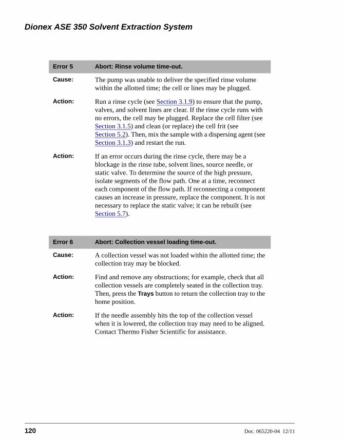
Dionex ASE 350 Solvent Extraction System
120 Doc. 065220-04 12/11
Error 5 Abort: Rinse volume time-out.
Cause: The pump was unable to deliver the specified rinse volume within the allotted time; the cell or lines may be plugged.
Action: Run a rinse cycle (see Section 3.1.9) to ensure that the pump, valves, and solvent lines are clear. If the rinse cycle runs with no errors, the cell may be plugged. Replace the cell filter (see Section 3.1.5) and clean (or replace) the cell frit (see Section 5.2). Then, mix the sample with a dispersing agent (see Section 3.1.3) and restart the run.
Action: If an error occurs during the rinse cycle, there may be a blockage in the rinse tube, solvent lines, source needle, or static valve. To determine the source of the high pressure, isolate segments of the flow path. One at a time, reconnect each component of the flow path. If reconnecting a component causes an increase in pressure, replace the component. It is not necessary to replace the static valve; it can be rebuilt (see Section 5.7).
Error 6 Abort: Collection vessel loading time-out.
Cause: A collection vessel was not loaded within the allotted time; the collection tray may be blocked.
Action: Find and remove any obstructions; for example, check that all collection vessels are completely seated in the collection tray. Then, press the Trays button to return the collection tray to the home position.
Action: If the needle assembly hits the top of the collection vessel when it is lowered, the collection tray may need to be aligned. Contact Thermo Fisher Scientific for assistance.
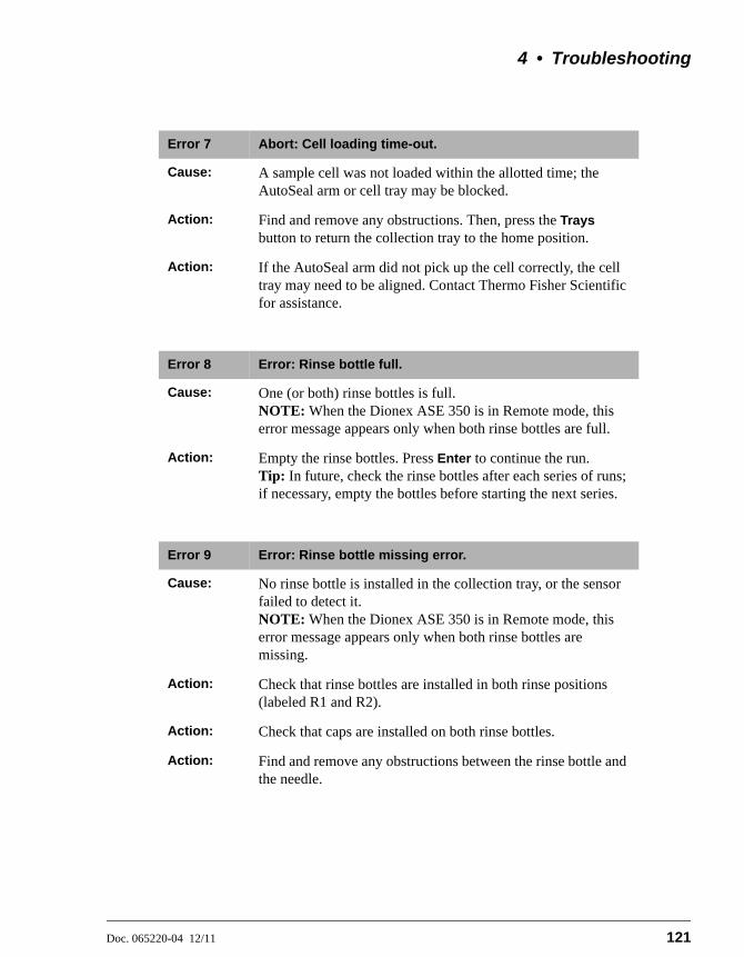
4 • Troubleshooting
Doc. 065220-04 12/11 121
Error 7 Abort: Cell loading time-out.
Cause: A sample cell was not loaded within the allotted time; the AutoSeal arm or cell tray may be blocked.
Action: Find and remove any obstructions. Then, press the Trays button to return the collection tray to the home position.
Action: If the AutoSeal arm did not pick up the cell correctly, the cell tray may need to be aligned. Contact Thermo Fisher Scientific for assistance.
Error 8 Error: Rinse bottle full.
Cause: One (or both) rinse bottles is full.NOTE: When the Dionex ASE 350 is in Remote mode, this error message appears only when both rinse bottles are full.
Action: Empty the rinse bottles. Press Enter to continue the run.Tip: In future, check the rinse bottles after each series of runs; if necessary, empty the bottles before starting the next series.
Error 9 Error: Rinse bottle missing error.
Cause: No rinse bottle is installed in the collection tray, or the sensor failed to detect it.NOTE: When the Dionex ASE 350 is in Remote mode, this error message appears only when both rinse bottles are missing.
Action: Check that rinse bottles are installed in both rinse positions (labeled R1 and R2).
Action: Check that caps are installed on both rinse bottles.
Action: Find and remove any obstructions between the rinse bottle and the needle.
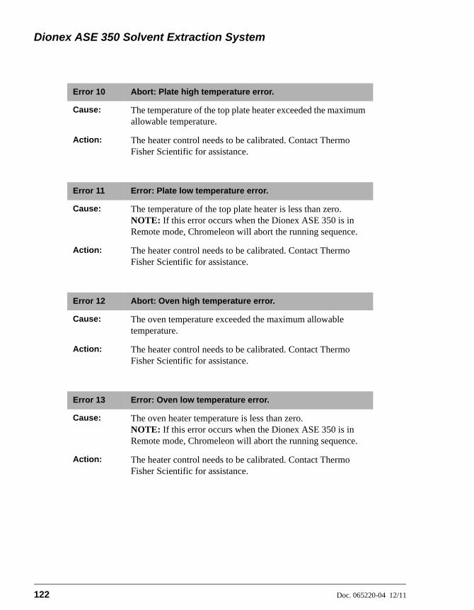
Dionex ASE 350 Solvent Extraction System
122 Doc. 065220-04 12/11
Error 10 Abort: Plate high temperature error.
Cause: The temperature of the top plate heater exceeded the maximum allowable temperature.
Action: The heater control needs to be calibrated. Contact Thermo Fisher Scientific for assistance.
Error 11 Error: Plate low temperature error.
Cause: The temperature of the top plate heater is less than zero.NOTE: If this error occurs when the Dionex ASE 350 is in Remote mode, Chromeleon will abort the running sequence.
Action: The heater control needs to be calibrated. Contact Thermo Fisher Scientific for assistance.
Error 12 Abort: Oven high temperature error.
Cause: The oven temperature exceeded the maximum allowable temperature.
Action: The heater control needs to be calibrated. Contact Thermo Fisher Scientific for assistance.
Error 13 Error: Oven low temperature error.
Cause: The oven heater temperature is less than zero.NOTE: If this error occurs when the Dionex ASE 350 is in Remote mode, Chromeleon will abort the running sequence.
Action: The heater control needs to be calibrated. Contact Thermo Fisher Scientific for assistance.
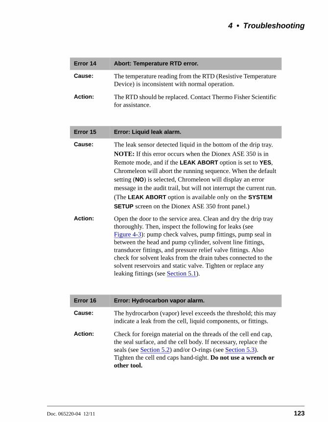
4 • Troubleshooting
Doc. 065220-04 12/11 123
Error 14 Abort: Temperature RTD error.
Cause: The temperature reading from the RTD (Resistive Temperature Device) is inconsistent with normal operation.
Action: The RTD should be replaced. Contact Thermo Fisher Scientific for assistance.
Error 15 Error: Liquid leak alarm.
Cause: The leak sensor detected liquid in the bottom of the drip tray.
NOTE: If this error occurs when the Dionex ASE 350 is in Remote mode, and if the LEAK ABORT option is set to YES, Chromeleon will abort the running sequence. When the default setting (NO) is selected, Chromeleon will display an error message in the audit trail, but will not interrupt the current run.
(The LEAK ABORT option is available only on the SYSTEM
SETUP screen on the Dionex ASE 350 front panel.)
Action: Open the door to the service area. Clean and dry the drip tray thoroughly. Then, inspect the following for leaks (see Figure 4-3): pump check valves, pump fittings, pump seal in between the head and pump cylinder, solvent line fittings, transducer fittings, and pressure relief valve fittings. Also check for solvent leaks from the drain tubes connected to the solvent reservoirs and static valve. Tighten or replace any leaking fittings (see Section 5.1).
Error 16 Error: Hydrocarbon vapor alarm.
Cause: The hydrocarbon (vapor) level exceeds the threshold; this may indicate a leak from the cell, liquid components, or fittings.
Action: Check for foreign material on the threads of the cell end cap, the seal surface, and the cell body. If necessary, replace the seals (see Section 5.2) and/or O-rings (see Section 5.3). Tighten the cell end caps hand-tight. Do not use a wrench or other tool.

Dionex ASE 350 Solvent Extraction System
124 Doc. 065220-04 12/11
Action: Open the door to the service area. Clean and dry the drip tray thoroughly. Then, inspect the following for leaks (see Figure 4-3): pump check valves, pump fittings, pump seal in between the head and pump cylinder, solvent line fittings, transducer fittings, and pressure relief valve fittings. Also check for solvent leaks from the drain tubes connected to the solvent reservoirs and static valve. Tighten or replace any leaking fittings (see Section 5.1).
Action: Go to the HYDROCARBON STATUS screen (see Section C.7) and reset the THRESHOLD.
Action: If the hydrocarbon sensor is tripped repeatedly, you may want to disable the sensor. For details, contact Thermo Fisher Scientific.NOTE: If the sensor is disabled, be sure to monitor the system for leaks that may cause an excessive hydrocarbon vapor level.
Action: If the hydrocarbon sensor is tripped repeatedly, you may have to replace the sensor (see Section 5.9).
Error 17 Error: Cell size error.
Cause: The AutoSeal arm or sensors have malfunctioned.NOTE: If this error occurs when the Dionex ASE 350 is in Remote mode, a message is displayed in the Chromeleon audit trail, but the current run is not interrupted.
Action: Contact Thermo Fisher Scientific for assistance.
Error 18 Error: AutoSeal close command was not successful.
Cause: The air supply is not reaching the AutoSeal arm.NOTE: If this error occurs when the Dionex ASE 350 is in Remote mode, Chromeleon will abort the running sequence.
Action: Check the air supply pressure. The air source should be between 0.41 and 1.38 MPa (60 and 200 psi); 0.69 MPa (100 psi) is recommended.

4 • Troubleshooting
Doc. 065220-04 12/11 125
Action: Check the SYSTEM AIR reading on the PRESSURE
REGULATORS screen (see Section C.3); it should be 0.34 0.02 MPa (50 3 psi).
Action: Check the AUTOSEAL reading on the PRESSURE
REGULATORS screen (see Section C.3); when the AutoSeal is closed, it should be 172.37 14 kPa (25 2 psi).
Action: Find and remove any obstructions that may be preventing AutoSeal arm movement.
Action: If the error message appears again, contact Thermo Fisher Scientific for assistance.
Error 19 Abort: AutoSeal open command was not successful.
Cause: The air supply is not reaching the AutoSeal arm.NOTE: If this error occurs when the Dionex ASE 350 is in Remote mode, Chromeleon will abort the running sequence.
Action: Check the air supply pressure. The air source should be between 0.41 and 1.38 MPa (60 and 200 psi); 0.69 MPa (100 psi) is recommended.
Action: Check the SYSTEM AIR reading on the PRESSURE
REGULATORS screen (see Section C.3); it should be 0.34 0.02 MPa (50 3 psi).
Action: Check the AUTOSEAL reading on the PRESSURE
REGULATORS screen (see Section C.3); when the AutoSeal is closed, it should be 172.37 14 kPa (25 2 psi).
Action: Find and remove any obstructions that may be preventing AutoSeal arm movement.
Action: If the error message appears again, contact Thermo Fisher Scientific for assistance.

Dionex ASE 350 Solvent Extraction System
126 Doc. 065220-04 12/11
Error 20 Error: AutoSeal go to tray command was not successful.
Cause: The air supply is not reaching the AutoSeal arm.NOTE: If this error occurs when the Dionex ASE 350 is in Remote mode, Chromeleon will abort the running sequence.
Action: Check the air supply pressure. The air source should be between 0.41 and 1.38 MPa (60 and 200 psi); 0.69 MPa (100 psi) is recommended.
Action: Check the SYSTEM AIR reading on the PRESSURE
REGULATORS screen (see Section C.3); it should be 0.34 0.02 MPa (50 3 psi).
Action: Find and remove any obstructions that may be preventing AutoSeal arm movement.
Action: If the error message appears again, contact Thermo Fisher Scientific for assistance.
Error 21 Error: AutoSeal go to oven command was not successful.
Cause: The air supply is not reaching the AutoSeal arm.NOTE: If this error occurs when the Dionex ASE 350 is in Remote mode, Chromeleon will abort the running sequence.
Action: Check the air supply pressure. The air source should be between 0.41 and 1.38 MPa (60 and 200 psi); 0.69 MPa (100 psi) is recommended.
Action: Check the SYSTEM AIR reading on the PRESSURE
REGULATORS screen (see Section C.3); it should be 0.34 0.02 MPa (50 3 psi).
Action: Find and remove any obstructions that may be preventing AutoSeal arm movement.
Action: If the error message appears again, contact Thermo Fisher Scientific for assistance.

4 • Troubleshooting
Doc. 065220-04 12/11 127
Error 22 Error: AutoSeal command rejected due to unsafe condition.
Cause: The cell tray sensor was unable to detect the tray at a cell position (not aligned with a cell).NOTE: If this error occurs when the Dionex ASE 350 is in Remote mode, Chromeleon will abort the running sequence.
Action: The cell tray may not be in the correct position. Abort the run (see Section 3.5.3), and then restart the run.
Action: The cell tray sensor has malfunctioned. Contact Thermo Fisher Scientific for assistance.
Cause: The AutoSeal arm is hitting the cell tray.
Action: The AutoSeal arm or cell tray is out of alignment. Contact Thermo Fisher Scientific for assistance.
Error 23 Error: Needle up command was not successful.
Cause: Insufficient air pressure supplied to the system.NOTE: If this error occurs when the Dionex ASE 350 is in Remote mode, Chromeleon will abort the running sequence.
Action: Check the air supply pressure. The air source should be between 0.41 and 1.38 MPa (60 and 200 psi); 0.69 MPa (100 psi) is recommended. Check the system air regulator pressure (see Section B.8). Check the delivery of air to the needle assembly.
Cause: Movement of the needle assembly is blocked.
Action: Find and remove any obstructions.
Cause: The needle sensor was unable to detect the needle in the up position.
Action: The sensor has malfunctioned. Contact Thermo Fisher Scientific for assistance.
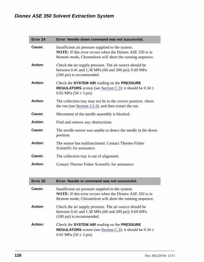
Dionex ASE 350 Solvent Extraction System
128 Doc. 065220-04 12/11
Error 24 Error: Needle down command was not successful.
Cause: Insufficient air pressure supplied to the system.NOTE: If this error occurs when the Dionex ASE 350 is in Remote mode, Chromeleon will abort the running sequence.
Action: Check the air supply pressure. The air source should be between 0.41 and 1.38 MPa (60 and 200 psi); 0.69 MPa (100 psi) is recommended.
Action: Check the SYSTEM AIR reading on the PRESSURE
REGULATORS screen (see Section C.3); it should be 0.34 0.02 MPa (50 3 psi).
Action: The collection tray may not be in the correct position. Abort the run (see Section 3.5.3), and then restart the run.
Cause: Movement of the needle assembly is blocked.
Action: Find and remove any obstructions.
Cause: The needle sensor was unable to detect the needle in the down position.
Action: The sensor has malfunctioned. Contact Thermo Fisher Scientific for assistance.
Cause: The collection tray is out of alignment.
Action: Contact Thermo Fisher Scientific for assistance.
Error 25 Error: Needle in command was not successful.
Cause: Insufficient air pressure supplied to the system.NOTE: If this error occurs when the Dionex ASE 350 is in Remote mode, Chromeleon will abort the running sequence.
Action: Check the air supply pressure. The air source should be between 0.41 and 1.38 MPa (60 and 200 psi); 0.69 MPa (100 psi) is recommended.
Action: Check the SYSTEM AIR reading on the PRESSURE
REGULATORS screen (see Section C.3); it should be 0.34 0.02 MPa (50 3 psi).
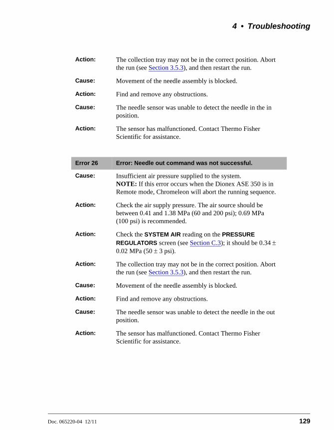
4 • Troubleshooting
Doc. 065220-04 12/11 129
Action: The collection tray may not be in the correct position. Abort the run (see Section 3.5.3), and then restart the run.
Cause: Movement of the needle assembly is blocked.
Action: Find and remove any obstructions.
Cause: The needle sensor was unable to detect the needle in the in position.
Action: The sensor has malfunctioned. Contact Thermo Fisher Scientific for assistance.
Error 26 Error: Needle out command was not successful.
Cause: Insufficient air pressure supplied to the system.NOTE: If this error occurs when the Dionex ASE 350 is in Remote mode, Chromeleon will abort the running sequence.
Action: Check the air supply pressure. The air source should be between 0.41 and 1.38 MPa (60 and 200 psi); 0.69 MPa (100 psi) is recommended.
Action: Check the SYSTEM AIR reading on the PRESSURE
REGULATORS screen (see Section C.3); it should be 0.34 0.02 MPa (50 3 psi).
Action: The collection tray may not be in the correct position. Abort the run (see Section 3.5.3), and then restart the run.
Cause: Movement of the needle assembly is blocked.
Action: Find and remove any obstructions.
Cause: The needle sensor was unable to detect the needle in the out position.
Action: The sensor has malfunctioned. Contact Thermo Fisher Scientific for assistance.

Dionex ASE 350 Solvent Extraction System
130 Doc. 065220-04 12/11
Error 27 Error: Needle command rejected due to unsafe condition.
Cause: The collection tray sensor was unable to detect the tray at a position that contains a collection vessel.NOTE: If this error occurs when the Dionex ASE 350 is in Remote mode, Chromeleon will abort the running sequence.
Action: The collection tray may not be in the correct position. Abort the run (see Section 3.5.3), and then restart the run.
Action: The sensor has malfunctioned. Contact Thermo Fisher Scientific for assistance.
Cause: The needle assembly is hitting the collection tray.
Action: The collection tray is out of alignment. Contact Thermo Fisher Scientific for assistance.
Error 28 Abort: Cell tray cannot find the requested position.
Cause: The cell tray is either physically blocked or is out of position.
Action: Find and remove any obstructions. Then, manually check the tray movement, using the Trays button. If the tray does not move freely, contact Thermo Fisher Scientific for assistance.
Error 29 Abort: Cell tray command rejected due to unsafe condition.
Cause: The AutoSeal arm is either in motion or is in an invalid position.
Action: Wait until the AutoSeal arm stops moving.
Action: If the error message appears again, contact Thermo Fisher Scientific for assistance.
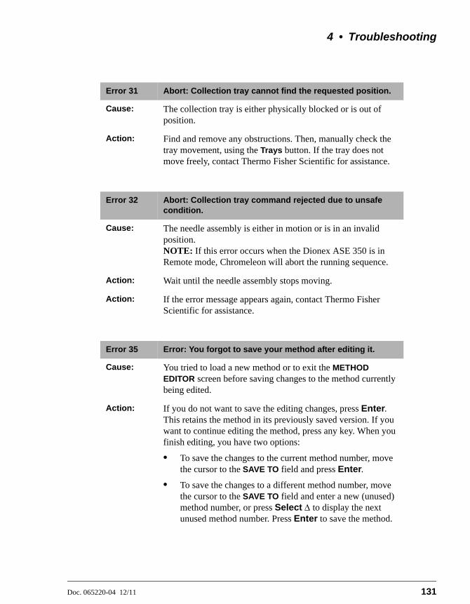
4 • Troubleshooting
Doc. 065220-04 12/11 131
Error 31 Abort: Collection tray cannot find the requested position.
Cause: The collection tray is either physically blocked or is out of position.
Action: Find and remove any obstructions. Then, manually check the tray movement, using the Trays button. If the tray does not move freely, contact Thermo Fisher Scientific for assistance.
Error 32 Abort: Collection tray command rejected due to unsafe condition.
Cause: The needle assembly is either in motion or is in an invalid position. NOTE: If this error occurs when the Dionex ASE 350 is in Remote mode, Chromeleon will abort the running sequence.
Action: Wait until the needle assembly stops moving.
Action: If the error message appears again, contact Thermo Fisher Scientific for assistance.
Error 35 Error: You forgot to save your method after editing it.
Cause: You tried to load a new method or to exit the METHOD EDITOR screen before saving changes to the method currently being edited.
Action: If you do not want to save the editing changes, press Enter. This retains the method in its previously saved version. If you want to continue editing the method, press any key. When you finish editing, you have two options:
• To save the changes to the current method number, move the cursor to the SAVE TO field and press Enter.
• To save the changes to a different method number, move the cursor to the SAVE TO field and enter a new (unused) method number, or press Select to display the next unused method number. Press Enter to save the method.

Dionex ASE 350 Solvent Extraction System
132 Doc. 065220-04 12/11
Error 36 Error: You forgot to save your sequence after editing it.
Cause: You tried to load a new sequence or to exit the SEQUENCE EDITOR screen before saving changes to the sequence currently being edited.
Action: If you do not want to save the editing changes, press Enter. This retains the sequence in its previously saved version. If you want to continue editing the sequence, press any key. When you finish editing, you have two options:
• To save the changes to the current sequence number, move the cursor to the SAVE TO field and press Enter.
• To save the changes to a different sequence number, move the cursor to the SAVE TO field and enter a new (unused) sequence number, or press Select to display the next unused sequence number. Press Enter to save the sequence.
Error 37 Error: Operator input value is not in range. Check prompt line at the bottom of the screen for the range of values allowed.
Cause: While editing a method or sequence, you entered an invalid parameter.
Action: Enter an acceptable value.
Error 38 Error: Usage Log screen, press Enter button to continue resetting parameter. Any other keypad entry will cancel process.
Cause: This error messages asks for confirmation that you want to reset a counter on the USAGE LOG screen (see Section C.4).
Action: To reset the counter, press Enter. To cancel the change, press any other keypad button.

4 • Troubleshooting
Doc. 065220-04 12/11 133
Error 39 Error: Method was not saved; there are one or more invalid fields. Enter zero in edit # field for a default method and re-enter desired conditions.
Cause: A method contains a parameter that conflicts with another parameter in the method. For example, if you change the cell type from stainless steel to zirconium, a cell size that was previously valid may now be out of range.
Action: Enter zero in the METHOD EDIT # field to display the default method parameters. Make any changes required, and then save the method to a new method number (see Section 3.2.1).Table 3-3 lists the values allowed for each parameter.
Error 40 Error: Sequence was not saved; there are one or more invalid fields. Methods in the sequence were also checked for valid fields.
Cause: A method in the sequence was not saved.
Action: Check that all methods have been saved.
Cause: A method contains an invalid parameter.
Action: Check for method parameters that are in conflict with each other. For example, if you change the cell type from stainless steel to zirconium, a cell size that was previously valid may now be out of range. Table 3-3 lists the values allowed for each parameter.
Error 43 Abort: The collection tray type (60-mL vials or 250-mL bottles) does not match the sequence entry.
Cause: The collection tray type specified in the sequence does not correspond to the tray type currently installed.
Action: If the collection vessels are 250-mL bottles:
• Go to the SEQUENCE EDITOR screen and check that NO INSERT is displayed.
• If a vial tray insert is installed, remove it.

Dionex ASE 350 Solvent Extraction System
134 Doc. 065220-04 12/11
Action: If the collection vessels are 60-mL vials:
• Go to the SEQUENCE EDITOR screen and check that INSERT is displayed.
• If a vial tray insert is not installed, install it now (see page 65).
Error 44 Error: Rinse tube is missing.
Cause: One (or both) of the rinse tubes is missing from the cell tray, or the sensors cannot detect them.NOTE: If this error occurs when the Dionex ASE 350 is in Remote mode, a message is displayed in the Chromeleon audit trail, but the current run is not interrupted.
Action: Check that rinse tubes are installed between positions 6 and 7 and positions 18 and 19 of the cell tray.
Error 45 Error: There are no rinse tubes.
Cause: The cell tray does not contain any rinse tubes, or the sensors cannot detect them.NOTE: If this error occurs when the Dionex ASE 350 is in Remote mode, Chromeleon will abort the running sequence.
Action: Check that rinse tubes are installed between positions 6 and 7 and positions 18 and 19 of the cell tray.
Action: If the error message appears again, the sensor has malfunctioned. Contact Thermo Fisher Scientific for assistance.
Action: The cell tray needs to be aligned. Contact Thermo Fisher Scientific for assistance.
4 • Troubleshooting
Doc. 065220-04 12/11 135
Error 46 Error: The rinse bottles are either missing or full. Please place an empty rinse bottle in R1 or R2. Then press the Enter button to continue the rinse process.
Cause: One (or both) rinse bottles is missing.NOTE: If this error occurs when the Dionex ASE 350 is in Remote mode, Chromeleon will abort the running sequence.
Action: Place a collection bottle in positions R1 and R2 in the collection tray. Press Enter to continue the run.To avoid having this error message reappear: Check the rinse bottles after each series of runs; if necessary, empty the bottles before starting the next series.
Cause: One (or both) rinse bottles is full.
Action: Empty the rinse bottles. Press Enter to continue the run.Tip: In future, check the rinse bottles after each series of runs; if necessary, empty the bottles before starting the next series.
Error 47 Error: The cell size is too large for the collection vessel capacity. Use 250-mL bottles for this cell size.
Cause: Although the cell tray contains 66-mL and/or 100-mL sample cells, 60-mL vials are installed as collection vessels.
Action: When using 66-mL or 100-mL sample cells, always install 250-mL collection bottles as the collection vessels.
Error 48 Abort: Pump error detected. Check pump seals, check valves, and check cell seals.
Cause: The expected pressure was not reached during the fill step.
Action: Replace the pump check valves (see Section 5.4).
Action: Check for foreign material on the threads of the cell end cap, the seal surface, and the cell body. If necessary, replace the seals (see Section 5.2) and/or O-rings (see Section 5.3). Tighten the cell end caps hand-tight. Do not use a wrench or other tool.
Dionex ASE 350 Solvent Extraction System
136 Doc. 065220-04 12/11
Action: Open the door to the service area. Inspect the following for leaks (see Figure 4-3): pump check valves, pump fittings, pump seal in between the head and pump cylinder, solvent line fittings, transducer fittings, and pressure relief valve fittings. Tighten or replace any leaking fittings (see Section 5.1).
Error 49 Abort: For this run, the method parameter cell type is zirconium. Only 66- and 100-mL cell sizes are allowed for zirconium. Sensors detected a smaller cell.
Cause: Only 66-mL and 100-mL cells are available in zirconium. The installed cell is smaller than this, indicating that the cell material is not zirconium.
Action: Either use the cell specified in the method or edit the method to match the cell type currently installed.
Error 50 Caution: The LOAD METHOD/SEQUENCE screen is not accessible during a run or rinse.
Cause: You tried to display the LOAD METHOD/SEQUENCE screen while a run or rinse was in progress.
Action: Wait until the task underway has finished before selecting this screen.
Error 51 Error: The safety shield is not in a safe position. Please close the safety shield and restart the run.
Cause: You tried to start a run while the safety shield was open. NOTE: If this error occurs when the Dionex ASE 350 is in Remote mode, Chromeleon will abort the running sequence.
Action: Close the safety shield and restart the run.

4 • Troubleshooting
Doc. 065220-04 12/11 137
Error 54 Error: For solvent saver mode, the cell size detected should match the cell size in the method.
Cause: The cell size installed in the tray does not match the cell size specified in the method.
Action: If the correct cells are installed, edit the method to specify this cell size. If the wrong cells are installed, replace them.
Error 60 Error: Changing this setting will cause sequence lines 20–33 to be deleted. Do you want to continue? Press Enter to continue. Press any other key to go back.
Cause: You changed the setting from INSERT to NO INSERT on the SEQUENCE EDITOR screen. Collection vessels cannot be loaded in positions 20–33 of the collection tray unless a vial tray insert is installed; thus, these sequence lines are no longer valid.NOTE: If this error occurs when the Dionex ASE 350 is in Remote mode, Chromeleon will abort the running sequence.
Action: If you want to delete lines 20–33 from the sequence, press Enter.
Action: If you do not want to delete lines 20–33 from the sequence, press any key other than Enter.
Error 63 Warning: Invalid entry while in remote control.
Cause: With the Dionex ASE 350 under Chromeleon control, you tried to edit a field on the front panel display or pressed a front panel button other than Trays, Stop, Contrast , or Contrast (the only buttons that are functional in Remote mode).
Action: Wait until Chromeleon finishes the function in process and then disconnect from Chromeleon control before making any changes from the Dionex ASE 350 front panel.

Dionex ASE 350 Solvent Extraction System
138 Doc. 065220-04 12/11
Error 64 Error: Collection vessel full.
Cause: The collection vessel is full.
Action: Empty the collection vessel, if needed. If there is a label or written information on the collection vessel, check that it is not blocking the area read by the sensor (see Figure 3-11).
Action: Check the cell size and rinse volume specified in the method; if it exceeds the volume of the collection vessel, reduce the rinse volume.
Action: If liquid drips continually into the collection vessel during the heating and static steps, it indicates a leak from the static valve. Rebuild the static valve (see Section 5.7).
Action: Viscous samples and plant samples may repeatedly trip the sensor. If you routinely extract these samples, you may want to disable the sensor. For details, contact Thermo Fisher Scientific.NOTE: If the sensor is disabled, be sure to monitor collection vessels to check for overfilling.
Error 65 Error: Collection vessel missing error.
Cause: No collection vessel is installed in the collection tray, or the sensor failed to detect it.
Action: Check that a collection vessel is installed in the position specified in the method.
Action: Find and remove any obstructions between the collection vessel and the needle.
Error 66 Error: Cell is missing.
Cause: No cell is installed, or the sensors cannot detect it.
Action: Check that a cell is installed in the position specified in the sequence.
4 • Troubleshooting
Doc. 065220-04 12/11 139
Action: If the error message appears again, the sensor has malfunctioned. Contact Thermo Fisher Scientific for assistance.
Action: The cell tray needs to be aligned. Contact Thermo Fisher Scientific for assistance.
Error 67 Error: There was a problem in reducing the cell pressure to a safe level under 15 psi before returning the cell to the carousel. The cell pressure may need to be calibrated or check for obstruction.
Cause: A blockage in the system; the cell or lines may be plugged.
Action: Run a rinse cycle (see Section 3.1.9) to ensure that the pump, valves, and solvent lines are clear. If the rinse cycle runs with no errors, the cell may be plugged. Replace the cell filter (see Section 3.1.5) and clean (or replace) the cell frit (see Section 5.2). Then, mix the sample with a dispersing agent (see Section 3.1.3) and restart the run.
Action: If an error occurs during the rinse cycle, there may be a blockage in the rinse tube, solvent lines, source needle, or static valve. To determine the source of the high pressure, isolate segments of the flow path. One at a time, reconnect each component of the flow path. If reconnecting a component causes an increase in pressure, replace the component. It is not necessary to replace the static valve; it can be rebuilt (see Section 5.7).
Cause: If the error message appears again, the cell pressure needs to be calibrated.
Action: The cell pressure cannot be calibrated by the user. Contact Thermo Fisher Scientific for assistance.

Dionex ASE 350 Solvent Extraction System
140 Doc. 065220-04 12/11
4.2 Liquid Leaks
• Missing or worn-out cell or rinse tube O-rings
Check the ends of the cell or rinse tube to verify that the O-rings are in place and in good condition (see Figure 4-1). If an O-ring has a hole size of less than 0.5 mm, replace it. If a white PTFE O-ring is discolored, replace it.
Figure 4-1. Inspecting O-Rings
Remove O-rings with a small flathead screwdriver (P/N 046985). Using the tool (P/N 049660) provided in the Dionex ASE 350 Ship Kit (P/N 066060), place a new O-ring (PTFE: P/N 049457, pkg. of 50; Viton: P/N 056325, pkg. of 50) over the opening in the end of the cell end cap and press it into place (see Figure 4-2).
Figure 4-2. Installing a Cell End Cap O-Ring
• Worn-out PEEK seal in cell end cap
Replace the seal (see Section 5.2).
• Leak in solvent flow path
Open the door to the service area (see Figure 2-1). (Rotate the three quarter-turn screws along the edge of the door and swing the door open.) Visually inspect the following for leaks (see Figure 4-3): pump check valves, pump fittings, solvent line fittings, transducer fittings, and pressure relief valve fittings. Tighten or replace any leaking fittings (see Section 5.1).
Verify that O-ringsare installed andin good condition
O-Ring Insertion Tool(P/N 049660)
Place O-ring in openingand press into place with insertion tool.
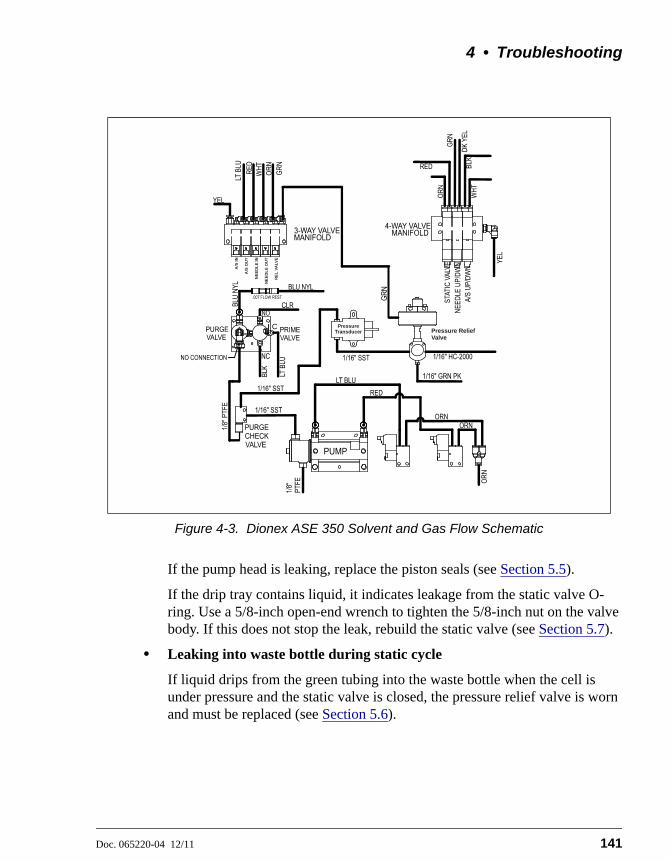
4 • Troubleshooting
Doc. 065220-04 12/11 141
If the pump head is leaking, replace the piston seals (see Section 5.5).
If the drip tray contains liquid, it indicates leakage from the static valve O-ring. Use a 5/8-inch open-end wrench to tighten the 5/8-inch nut on the valve body. If this does not stop the leak, rebuild the static valve (see Section 5.7).
• Leaking into waste bottle during static cycle
If liquid drips from the green tubing into the waste bottle when the cell is under pressure and the static valve is closed, the pressure relief valve is worn and must be replaced (see Section 5.6).
Figure 4-3. Dionex ASE 350 Solvent and Gas Flow Schematic
C Pressure Transducer
A/S
IN
RE
L V
ALV
E
Pressure ReliefValve
A/S
OU
T
NE
ED
LE
IN
NE
ED
LE
OU
T
Dionex ASE 350 Solvent Extraction System
142 Doc. 065220-04 12/11
• Leaking into collection vessel during static cycle
Check the tip of the source needle (see Figure 5-25) in the collection vessel. If liquid drips from the source needle into the collection vessel during the static cycle (when the static valve should be closed), the static valve seals are worn and the valve must be rebuilt (see Section 5.7).
4.3 Gas/Air Leaks
Gas/air leaks are usually audible. In addition, excessive gas/air consumption often indicates a leak. If you suspect a leak, check the following locations: the rear panel, the solvent reservoirs, and the connections inside the service area. Listen for leaks and run your hand over connections to feel for escaping gas.
If you find a loose connection, push the tubing firmly onto its fitting. If the fitting or tubing continues to leak, replace it (see Section 5.1).
4.4 Stopped System
• Operating error occurred
Check the display screen or Chromeleon audit trail for error messages. If a message is displayed, note the error number and refer to Section 4.1 for troubleshooting guidance.
• Method or sequence complete
Check the display screen or Chromeleon audit trail for error messages. If no messages are displayed, the Dionex ASE 350 probably stopped because the method or sequence had finished.
During method control, the Dionex ASE 350 runs samples sequentially until it reaches an empty cell or collection vessel position or, if the trays are full, until all samples have been run and the trays have returned to positions 1.
During sequence control, the Dionex ASE 350 runs according to each line defined in the sequence. A sequence is complete when no more lines are defined or when one of these fields contains a zero: BTL/VIAL #, CELL #, or METHOD #.

4 • Troubleshooting
Doc. 065220-04 12/11 143
• Electrical cables improperly installed
Open the door to the service area (see Figure 2-1). (Rotate the three quarter-turn screws along the edge of the door and swing the door open.) Check that all electrical cables are seated properly in the connectors on the printed circuit boards.

Dionex ASE 350 Solvent Extraction System
144 Doc. 065220-04 12/11

Doc. 065220-04 12/11 145
5 • Service
This chapter describes Thermo Scientific Dionex ASE 350 Accelerated Solvent Extractor service and repair procedures that users can perform. All procedures not included here, including electronics-related repair procedures, must be performed by a qualified Thermo Fisher Scientific representative. For assistance, contact Technical Support for Dionex products. In the U.S. or Canada, call 1-800-346-6390. Outside the U.S. or Canada, call the nearest Thermo Fisher Scientific office.
Before replacing any parts, review the troubleshooting information in Chapter 4 to isolate the cause of the problem.
5.1 Replacing Tubing and Fittings
Use a 1/4-inch open-end wrench (P/N 014605) to tighten any leaking fittings. Do not overtighten!
If tightening a fitting does not stop a leak, the tubing and fitting assembly must be replaced. Contact Thermo Fisher Scientific for assistance.
5.2 Replacing the Cell End Cap Seal
A worn PEEK seal is deeply grooved and will fail to form a tight seal between the cell cap and body during a run, causing leaks.
1. Unscrew the cell end cap from the cell body.
Substituting non-Dionex/Thermo Scientific parts (extraction cells,extraction cell components, valves, etc.) may impair the performanceof the Dionex ASE 350, thereby voiding the product warranty. Refer tothe warranty statement in the Dionex Terms and Conditions for moreinformation.
Wear safety glasses when removing the old snap ring from the cellend cap or installing a new snap ring.

Dionex ASE 350 Solvent Extraction System
146 Doc. 065220-04 12/11
2. Remove the snap ring from the end cap, using the snap ring tool (P/N 056684) provided in the Dionex ASE 350 Ship Kit (P/N 066060). (The procedure for stainless steel and zirconium end caps is identical. The photos show a stainless steel end cap.)
a. Insert the pointed ends of the tool into the two holes in the snap ring (see Figure 5-1).
b. Squeeze the handles of the tool together to reduce the diameter of the ring. At the same time, carefully pull the ring out of the end cap.
c. Carefully release the handles of the tool and remove the ring from the tool.
Figure 5-1. Removing the Snap Ring
Le port de lunettes de sécurité est requis lors du changement del’anneau de serrage sur le bouchon des cellules d’extraction.
Tragen Sie eine Schutzbrille, wenn Sie den alten Sicherungsring vonder Verschlusskappe der Zelle entfernen oder wenn Sie einen neuenSicherungsring installieren.
Do not disassemble the cell end cap after each use. This can causethe seal to fail prematurely.
Cell End Cap
Snap RingTool

5 • Service
Doc. 065220-04 12/11 147
3. Remove the cap insert (see Figure 5-2). Remove the PEEK seal from the groove in the bottom of the cap insert.
4. Remove the frit from the bottom of the end cap.
5. Clean the frit by sonicating it in solvent (or replace it).
Figure 5-2. Cell End Cap Disassembled
6. Refer to Figure 5-3 and the following steps to reassemble the sample cell:
a. Place the frit (either cleaned or new) into the bottom of the end cap.
b. Press a new PEEK seal (P/N 061687, pkg. 50) into the bottom of the cap insert.
c. Align the pins in the cap insert with the grooves in the end cap and then place the insert, with the seal facing down, into the end cap.
7. With the end cap assembly upright on the workbench, install the snap ring:
a. Insert the snap ring tool (P/N 056684) into the holes on the snap ring.
b. Squeeze the tool handles to bring the ends of the ring together.
c. Insert the ring into the end cap. Using your fingers, push the ring under the lip of the end cap. After verifying that the entire ring is under the lip, release the tension on the tool and remove the tool from the ring.
d. Screw the end cap back onto the cell body and hand-tighten.
Cell End Cap
Snap Ring
Cap Insert
Seal
Frit
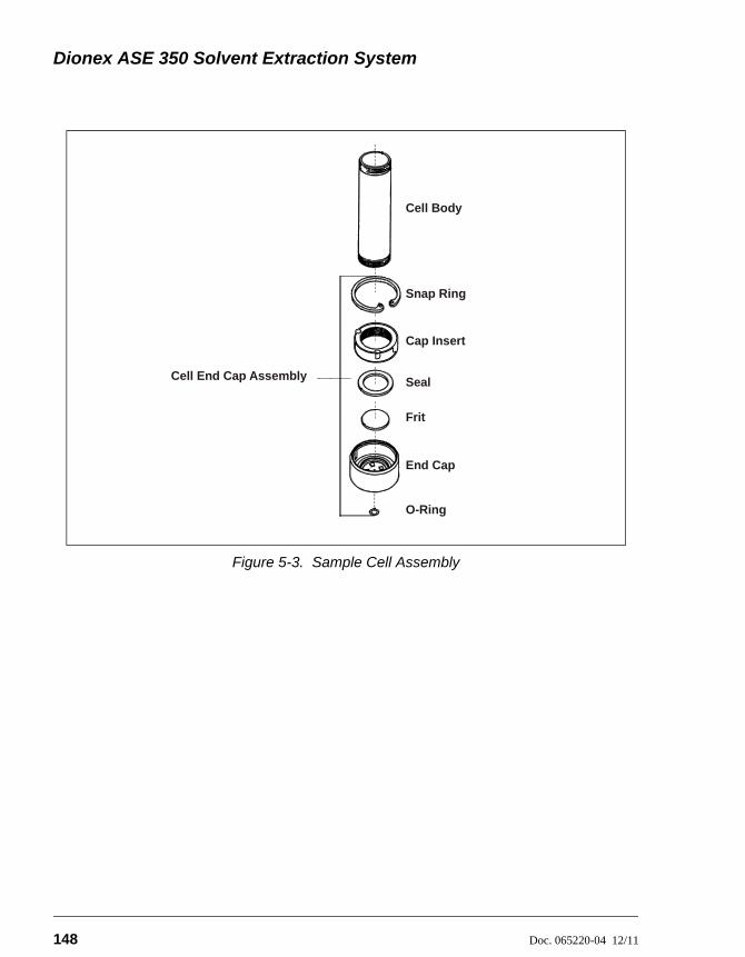
Dionex ASE 350 Solvent Extraction System
148 Doc. 065220-04 12/11
Figure 5-3. Sample Cell Assembly
Cell Body
Snap Ring
Cap Insert
Seal
End Cap
O-Ring
Cell End Cap Assembly
Frit

5 • Service
Doc. 065220-04 12/11 149
5.3 Replacing the Cell End Cap O-Ring
1. Locate the small flathead screwdriver (P/N 046985) and the O-ring insertion tool (P/N 049660) provided in the Dionex ASE 350 Ship Kit (P/N 066060).
2. Insert the tip of the screwdriver into the end cap and carefully pick out the O-ring. (This may be easier to do if you first remove the cap from the cell body and place it flat on the workbench.)
3. Place a new O-ring (PTFE: P/N 049457, pkg. of 50; Viton: P/N 056325, pkg. of 50) over the opening in the end of the cell end cap. Press the O-ring into place, using the O-ring insertion tool (see Figure 5-4).
Figure 5-4. Installing a Cell End Cap O-Ring
Be careful not to scratch the interior of the cell end cap wheninstalling or removing the cell O-ring. Scratches on the sealingsurface will prevent the O-ring from sealing properly and may result inleaks during operation.
O-Ring Insertion Tool(P/N 049660)
Place O-ring in openingand press into place with insertion tool.
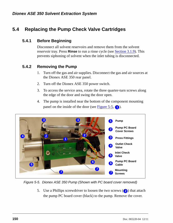
Dionex ASE 350 Solvent Extraction System
150 Doc. 065220-04 12/11
5.4 Replacing the Pump Check Valve Cartridges
5.4.1 Before Beginning
Disconnect all solvent reservoirs and remove them from the solvent reservoir tray. Press Rinse to run a rinse cycle (see Section 3.1.9). This prevents siphoning of solvent when the inlet tubing is disconnected.
5.4.2 Removing the Pump
1. Turn off the gas and air supplies. Disconnect the gas and air sources at the Dionex ASE 350 rear panel.
2. Turn off the Dionex ASE 350 power switch.
3. To access the service area, rotate the three quarter-turn screws along the edge of the door and swing the door open.
4. The pump is installed near the bottom of the component mounting
panel on the inside of the door (see Figure 5-5, ).
5. Use a Phillips screwdriver to loosen the two screws ( ) that attach
the pump PC board cover (black) to the pump. Remove the cover.
Figure 5-5. Dionex ASE 350 Pump (Shown with PC board cover removed)
11
Pump
Outlet Check Valve
2
Pump PC Board Cable
4
5
3
1
Press Fittings
Pump PC Board Cover Screws
1
3
4
5
7
6
Inlet Check Valve
2 2
3
6
77
Mounting Screws
22
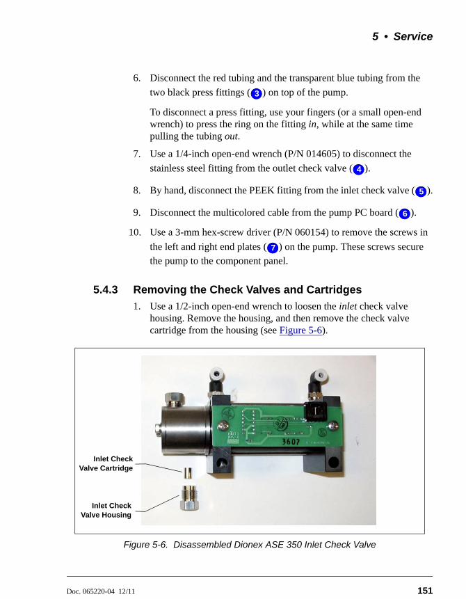
5 • Service
Doc. 065220-04 12/11 151
6. Disconnect the red tubing and the transparent blue tubing from the
two black press fittings ( ) on top of the pump.
To disconnect a press fitting, use your fingers (or a small open-end wrench) to press the ring on the fitting in, while at the same time pulling the tubing out.
7. Use a 1/4-inch open-end wrench (P/N 014605) to disconnect the
stainless steel fitting from the outlet check valve ( ).
8. By hand, disconnect the PEEK fitting from the inlet check valve ( ).
9. Disconnect the multicolored cable from the pump PC board ( ).
10. Use a 3-mm hex-screw driver (P/N 060154) to remove the screws in
the left and right end plates ( ) on the pump. These screws secure
the pump to the component panel.
5.4.3 Removing the Check Valves and Cartridges
1. Use a 1/2-inch open-end wrench to loosen the inlet check valve housing. Remove the housing, and then remove the check valve cartridge from the housing (see Figure 5-6).
Figure 5-6. Disassembled Dionex ASE 350 Inlet Check Valve
33
44
55
46
57
Inlet CheckValve Cartridge
Inlet CheckValve Housing

Dionex ASE 350 Solvent Extraction System
152 Doc. 065220-04 12/11
2. Turn the pump over, so that the outlet check valve is facing down.
3. Use a 1/2-inch open-end wrench to loosen the outlet check valve housing. Remove the housing, and then remove the check valve cartridge from the housing.
NOTE The housing for the inlet checkvalve assembly has a 1/4-28port. The housing for the outletcheck valve assembly has a 10-32 port (see Figure 5-7).
Figure 5-7. Check Valve Housings
5.4.4 Installing New Check Valve Cartridges
1. Install the new inlet cartridge (P/N 047755) in the inlet check valve housing so that the double-hole end of the cartridge is visible (see Figure 5-8).
2. Install the new outlet cartridge (P/N 057346) in the outlet check valve housing so that the arrow on the cartridge points down.
Figure 5-8. Check Valve Assemblies
5.4.5 Reinstalling the Check Valves
1. Install the inlet check valve assembly on the bottom of the pump head.
2. Install the outlet check valve assembly on the top of the pump head.
Inlet Check Valve:1/4-28 Port
Outlet Check Valve:10-32 Port
Double-hole
Inlet CheckValve
Flow
Flow
OutletCheckValve

5 • Service
Doc. 065220-04 12/11 153
3. Tighten the check valves fingertight, and then use a wrench to tighten an additional one-eighth to one-quarter turn.
5.4.6 Cleaning the Check Valves
Clean the check valves if new check valves are unavailable.
1. Place the check valve housings and cartridges in a beaker with methanol. Sonicate or agitate for several minutes.
2. Rinse each check valve housing and cartridge thoroughly with filtered, deionized water.
3. Reinstall the check valves on the pump.
5.4.7 Reinstalling the Pump
1. Reinstall the pump on the component panel.
2. Reconnect the two air lines to the press fittings on top of the pump.
3. Reconnect the solvent lines to the inlet and outlet check valve housings.
4. Reconnect the multicolored cable to the pump PC board.
5. Reinstall the pump PC board cover.
6. Close the service area door.
5.4.8 Completing the Procedure
1. Reinstall the solvent reservoirs.
2. Reconnect the gas and air sources at the Dionex ASE 350 rear panel. Turn on the gas and air supplies.
3. Turn on the Dionex ASE 350 power switch.
Overtightening may damage the pump head and the check valvehousing and crush the check valve seats.

Dionex ASE 350 Solvent Extraction System
154 Doc. 065220-04 12/11
5.5 Replacing the Pump Seals
5.5.1 Before Beginning
Disconnect all solvent reservoirs and remove them from the solvent reservoir tray. Press Rinse to run a rinse cycle (see Section 3.1.9). This prevents siphoning of solvent when the inlet tubing is disconnected.
5.5.2 Removing the Pump
Follow the instructions in “Removing the Pump” on page 150.
5.5.3 Replacing the Piston High-Pressure Seal
1. Use a 3-mm hex driver (P/N 060154) or wrench to loosen and remove the two screws securing the pump head to the body.
2. Slide the pump head straight off the pump (see Figure 5-9).
3. Turn the pump head over so that the open end is facing down. The tan piston guide (see Figure 5-10) should drop out of the head; if it does not, gently tap the head on the workbench to dislodge the guide. Save the piston guide (it will be reinstalled in Step 7).
Lateral motion while disengaging the pump head from the pump maybreak the piston.
Figure 5-9. Removing the Pump Head

5 • Service
Doc. 065220-04 12/11 155
4. If tapping the head on the bench does not remove the piston guide, use the wooden end of a cotton-tipped swab to pry the guide out of the pump head. Discard the used piston guide.
5. To remove the orange high-pressure seal from the pump head, insert the wooden end of a cotton-tipped swab and pry out the seal. Discard the seal.
6. Hold the new high-pressure seal (P/N 066162), with the smaller diameter (ringed) side of the seal facing down, and drop it into the pump head cavity.
7. If the piston guide was easily removed from the pump head (see Step 3), place the original piston guide on top of the high-pressure seal and firmly press it into place. This also seats the high-pressure seal in the pump head.
If you had to pry the piston guide out of the pump head (Step 4), install a new piston guide (P/N 066109) as described above. The original piston guide may have been scratched during removal, so do not use it again. A scratched guide will not seal properly.
Figure 5-10. Replacing the Dionex ASE 350 Piston High-Pressure Seal
Do not use a sharp tool (such as tweezers) to remove or install thepiston high-pressure seal. This will scratch the inside of the pumphousing; these scratches will prevent a proper seal and causeleakage.
High-Pressure Seal
Piston Guide

Dionex ASE 350 Solvent Extraction System
156 Doc. 065220-04 12/11
8. Reinstall the pump head onto the pump. Make sure the outlet check valve is oriented upward.
5.5.4 Replacing the Piston Air Seal
1. Remove the PC board from the side of the pump (see Figure 5-11, view A).
2. Loosen the two bolts that hold the two pump end plates together (see Figure 5-11, view B).
3. Remove the right end plate from the pump cylinder (see Figure 5-12).
Figure 5-11. Removing the Pump PC Board and End Plate Bolts
Figure 5-12. Removing the Pump Right End Plate
A B
Pump End Plate
Pump Cylinder
Right End Plate
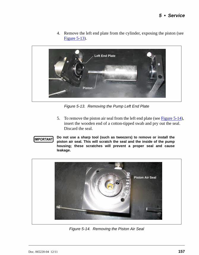
5 • Service
Doc. 065220-04 12/11 157
4. Remove the left end plate from the cylinder, exposing the piston (see Figure 5-13).
5. To remove the piston air seal from the left end plate (see Figure 5-14), insert the wooden end of a cotton-tipped swab and pry out the seal. Discard the seal.
Figure 5-13. Removing the Pump Left End Plate
Do not use a sharp tool (such as tweezers) to remove or install thepiston air seal. This will scratch the seal and the inside of the pumphousing; these scratches will prevent a proper seal and causeleakage.
Figure 5-14. Removing the Piston Air Seal
Left End Plate
Piston
Piston Air Seal

Dionex ASE 350 Solvent Extraction System
158 Doc. 065220-04 12/11
6. Insert the new piston air seal (P/N 066163), with the closed end facing down, into the end plate. Gently press the seal into place with a cotton-tipped swab (or other tool with a soft tip).
7. Gently insert the piston into the new seal in the left end plate. Push the pump cylinder over the O-ring on the left end plate. Push the pump cylinder over the O-ring on the right end plate.
8. Loosely secure the pump cylinder to the end plates with the two bolts removed previously.
9. Place the assembled pump on a flat surface. Make sure all four alignment marks on the pump cylinder and the end plates are aligned (see Figure 5-15). Press down on the end plates to square them with each other. The pump should sit evenly on the flat surface without rocking.
10. Tighten the two bolts evenly.
11. Reattach the PC board to the side of the pump.
5.5.5 Reinstalling the Pump
1. Reinstall the pump on the component panel.
2. Reconnect the red gas line to the left press fitting on top of the pump. Reconnect the transparent blue gas line to the right press fitting.
3. Connect the solvent lines to the inlet and outlet check valve housings.
Figure 5-15. Alignment Marks on Pump Cylinder and End Plates
5 • Service
Doc. 065220-04 12/11 159
4. Reconnect the multicolored cable to the pump PC board.
5. Reinstall the pump PC board cover.
5.5.6 Completing the Procedure
1. Close the door to the service area.
2. Reinstall the solvent reservoirs.
3. Reconnect the gas and air sources at the Dionex ASE 350 rear panel. Turn on the gas and air supplies.
4. Turn on the Dionex ASE 350 power switch.
5. Reset the PUMP SEAL STROKES counter on the front panel USAGE
LOG screen (see Section C.4).
– or –
If the Dionex ASE 350 is running under Chromeleon control, contact Thermo Fisher Scientific to reset the TotalPumpSealStrokes counter on the Wellness panel (see Section 2.5.3).

Dionex ASE 350 Solvent Extraction System
160 Doc. 065220-04 12/11
5.6 Replacing the Pressure Relief Valve
1. Turn off the gas and air supplies. Disconnect the gas and air sources at the Dionex ASE 350 rear panel.
2. Turn off the Dionex ASE 350 power switch.
3. To access the service area, rotate the three quarter-turn screws along the edge of the door and swing the door open.
4. The pressure relief valve is installed (see Figure 5-16, ) directly above the pump on the component mounting panel on the inside of the door. Disconnect
the green gas tubing ( ) from the press fitting on the valve.
To disconnect a press fitting, use your fingers (or a small open-end wrench) to press the ring on the fitting in, while at the same time pulling the tubing out.
5. Use a 1/4-inch open-end wrench (P/N 014605) to disconnect the stainless steel line ( ) from the left side of the valve. (This tubing connects to the pump transducer.)
6. Use the 1/4-inch open-end wrench to disconnect the Hastelloy™ line ( ) from the right side of the valve. (This tubing connects to the upper AutoSeal arm.)
Figure 5-16. Connections to the Pressure Relief Valve
11
22
33
44
Pressure Relief Valve
Hastelloy Line
Green PEEK Waste Line
Stainless Steel Line
Green Gas Tubing2
4
5
3
1
1
3
45
2

5 • Service
Doc. 065220-04 12/11 161
7. Use the 1/4-inch open-end wrench to disconnect the green PEEK waste line ( ) from the front of the valve.
8. Use a 9/64-inch Allen wrench to loosen the hex screw (black) on the right side of the clamp ring, behind the valve base (see Figure 5-17).
Figure 5-17. Removing the Allen Hex Screw
9. Pull the old valve off the valve base.
10. Insert the new pressure relief valve (P/N 048889) onto the valve base. Tighten the Allen hex screw on the clamp ring.
11. Reconnect all of the lines.
12. Close the service area door.
13. Reconnect the gas and air sources at the Dionex ASE 350 rear panel. Turn on the gas and air supplies.
14. Turn on the Dionex ASE 350 power switch.
55
Allen Hex Screw (Not visible in photo)
Pressure Relief Valve

Dionex ASE 350 Solvent Extraction System
162 Doc. 065220-04 12/11
5.7 Rebuilding the Static Valve
Leaking from the source needle into the collection vessel when the static valve is closed indicates that the static valve is worn and must be rebuilt. The rebuild procedure consists of replacing a few parts (an O-ring, a filter, and two seals) and then cleaning the inside of the valve body.
Before proceeding, check that the following kits are on hand. The kits contain the replacement parts and special tools required to rebuild the valve.
• Order a Static Valve Repair Kit (P/N 068115) each time the valve requires rebuilding.
• Order a Static Valve Tool Kit (P/N 068116) only the first time the valve requires rebuilding. Figure 5-18 illustrates the tools in the kit.
Part Number Item Quantity
065254 Dionex ASE 150/Dionex ASE 350 Static Valve Repair Kit Instructions
1
066165 High-pressure flangeless seal 2
067326 Perlast™ O-ring 1
067327 Zirconium filter 1
Table 5-1. Static Valve Repair Kit Contents
Part Number Item Quantity
049293 Tubing, orange (extension tubing) 60.96 cm (24 in)
057395 Union (for extension tubing) 1
067394 Piston-side seal insertion tool 1
067395 Inlet-side seal insertion tool 1
068117 Alignment tool 1
068118 Spacer tool 1
068119 Push screw tool 1
068245 Seal removal tool 1
Table 5-2. Static Valve Tool Kit Contents
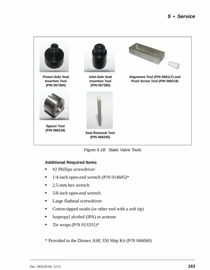
5 • Service
Doc. 065220-04 12/11 163
Additional Required Items
• #2 Phillips screwdriver
• 1/4-inch open-end wrench (P/N 014605)*
• 2.5-mm hex wrench
• 5/8-inch open-end wrench
• Large flathead screwdriver
• Cotton-tipped swabs (or other tool with a soft tip)
• Isopropyl alcohol (IPA) or acetone
• Tie wraps (P/N 013331)*
* Provided in the Dionex ASE 350 Ship Kit (P/N 066060)
Figure 5-18. Static Valve Tools
Piston-Side Seal Insertion Tool (P/N 067394)
Inlet-Side Seal Insertion Tool (P/N 067395)
Alignment Tool (P/N 068117) and Push Screw Tool (P/N 068119)
Spacer Tool (P/N 068118)
Seal Removal Tool (P/N 068245)

Dionex ASE 350 Solvent Extraction System
164 Doc. 065220-04 12/11
5.7.1 Removing the Static Valve from the System
1. Turn off the gas and air supplies. Disconnect the gas and air sources at the Dionex ASE 350 rear panel.
2. Turn off the Dionex ASE 350 power switch.
3. Close the safety shield.
4. Use a Phillips screwdriver to remove the four screws along the top of the safety shield (see Figure 5-19). (The screws attach the shield to the sliders.) Remove the safety shield and set it aside. Do not move the sliders.
Figure 5-19. Removing the Safety Shield
Remove screws (4) in safety shield
Sliders

5 • Service
Doc. 065220-04 12/11 165
5. Note the three pieces of tubing routed underneath the upper drip tray and held in place with tie wraps. Cut off the tie wrap indicated in Figure 5-20.
6. Remove the three screws that hold the drip tray in place under the cell tray. (There is a screw in the back of the tray, in the front, and on the right.) Slowly move the drip tray down and to the right; this action will pull the drain tubing connected to the drip tray through the hole in the wall that separates the service area from the trays.
Gently pull just enough of the drain tube through the hole to allow you to place the drip tray on top of the collection tray.
NOTE The drain tube is attached to the drip tray via abarbed fitting. Be careful not to break the barbor kink the drain tube.
Figure 5-20. Tie Wrap Removal
Upper Drip Tray (Below cell tray)Cut off this
tie wrap
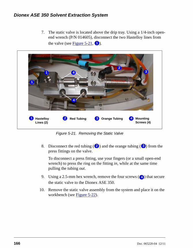
Dionex ASE 350 Solvent Extraction System
166 Doc. 065220-04 12/11
7. The static valve is located above the drip tray. Using a 1/4-inch open-end wrench (P/N 014605), disconnect the two Hastelloy lines from
the valve (see Figure 5-21, ).
8. Disconnect the red tubing ( ) and the orange tubing ( ) from the press fittings on the valve.
To disconnect a press fitting, use your fingers (or a small open-end wrench) to press the ring on the fitting in, while at the same time pulling the tubing out.
9. Using a 2.5-mm hex wrench, remove the four screws ( ) that secure
the static valve to the Dionex ASE 350.
10. Remove the static valve assembly from the system and place it on the workbench (see Figure 5-22).
Figure 5-21. Removing the Static Valve
11
Hastelloy Lines (2)
Red Tubing2
3
1
1
12
Orange Tubing Mounting Screws (4)
43
4
4
12 13
44

5 • Service
Doc. 065220-04 12/11 167
11. Using a 2.5-mm hex wrench, remove the two mounting screws that secure the valve body to the base plate of the valve assembly.
12. Follow these steps to remove the piston from the static valve:
a. Locate the slot in the piston holder. If necessary, rotate the piston holder so that the opening in the slot faces up.
b. Guide the piston out of the piston holder by lifting the valve body straight up. (This removes both the piston and the valve body.) Do not drop the piston.
c. Pull the piston out of the valve body and place in a secure location.
Figure 5-22. Static Valve
Dropping the piston may cause scratches or breakage. If the piston isdamaged, it cannot be used again and must be replaced.
Mounting Screws
ValveBody
Piston Holder
Piston
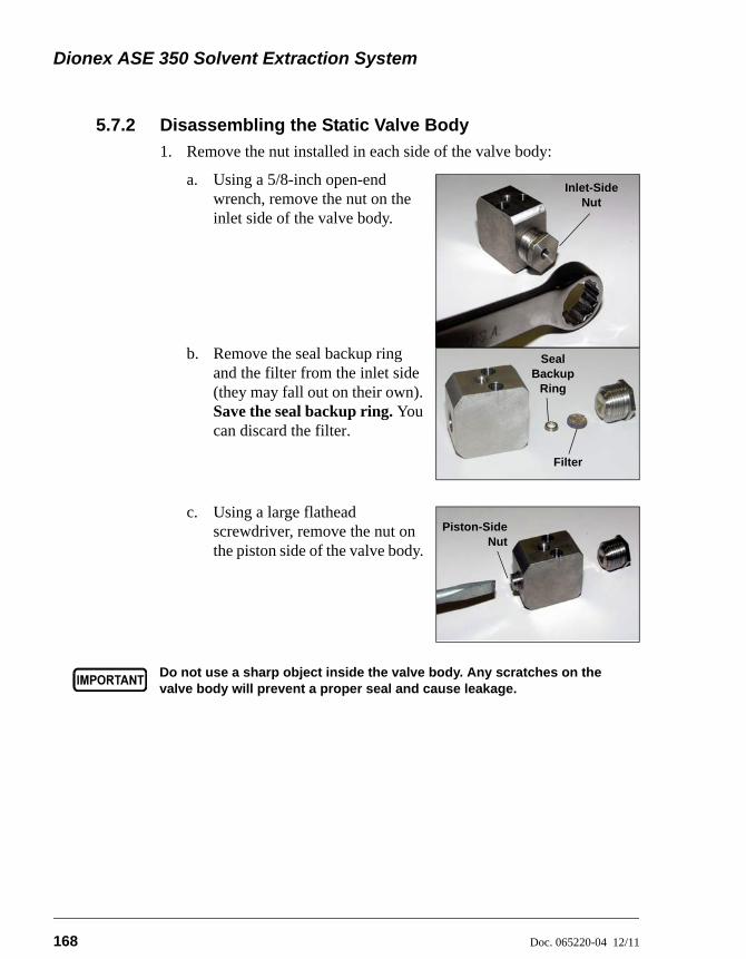
Dionex ASE 350 Solvent Extraction System
168 Doc. 065220-04 12/11
5.7.2 Disassembling the Static Valve Body
1. Remove the nut installed in each side of the valve body:
a. Using a 5/8-inch open-end wrench, remove the nut on the inlet side of the valve body.
b. Remove the seal backup ring and the filter from the inlet side (they may fall out on their own). Save the seal backup ring. You can discard the filter.
c. Using a large flathead screwdriver, remove the nut on the piston side of the valve body.
Do not use a sharp object inside the valve body. Any scratches on thevalve body will prevent a proper seal and cause leakage.
Inlet-Side Nut
Seal Backup
Ring
Filter
Piston-SideNut
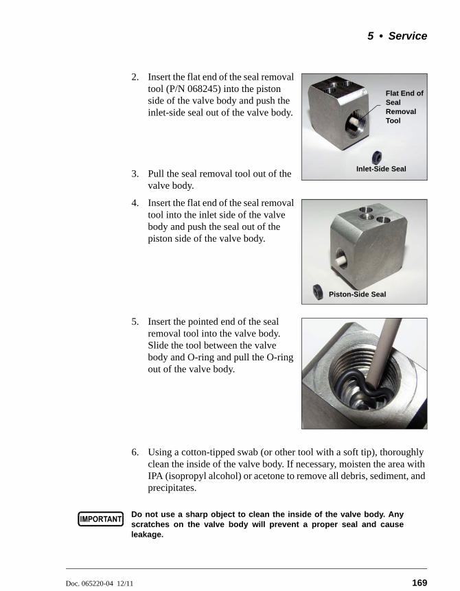
5 • Service
Doc. 065220-04 12/11 169
2. Insert the flat end of the seal removal tool (P/N 068245) into the piston side of the valve body and push the inlet-side seal out of the valve body.
3. Pull the seal removal tool out of the valve body.
4. Insert the flat end of the seal removal tool into the inlet side of the valve body and push the seal out of the piston side of the valve body.
5. Insert the pointed end of the seal removal tool into the valve body. Slide the tool between the valve body and O-ring and pull the O-ring out of the valve body.
6. Using a cotton-tipped swab (or other tool with a soft tip), thoroughly clean the inside of the valve body. If necessary, moisten the area with IPA (isopropyl alcohol) or acetone to remove all debris, sediment, and precipitates.
Do not use a sharp object to clean the inside of the valve body. Anyscratches on the valve body will prevent a proper seal and causeleakage.
Inlet-Side Seal
Flat End of Seal Removal Tool
Piston-Side Seal

Dionex ASE 350 Solvent Extraction System
170 Doc. 065220-04 12/11
5.7.3 Installing the New Seals
1. Push the piston through the piston-side seal insertion tool (P/N 067394).
2. Wet a new seal (P/N 066165) with IPA (isopropyl alcohol) for lubrication.
3. Note that one side of the seal is flat, while the other side contains an O-ring. Orient the O-ring side of the seal so that it faces away from the tool, and then slide the seal onto the piston.
4. Place the valve body, with the piston side (small opening) facing up, on the workbench.
5. Rest your thumbs on the back of the tool and press down firmly (with equal pressure) on both the left and right sides of the tool. You should hear a snap as the new seal is seated in the valve body. Remove the piston and the tool from the valve body.
NOTE: If there is no audible snap, check the seal for damage. An undamaged seal will lie completely flat in the valve body, with no visible edges. If the seal is damaged, remove it from the valve body. Contact Thermo Fisher Scientific to order a replacement seal.
Do not use a sharp object inside of the valve body. Any scratches onthe valve body will prevent a proper seal and allow leakage.
Piston
Seal
Piston-Side Seal Insertion Tool
Piston-Side Seal Insertion Tool
Piston
Seal O-Ring
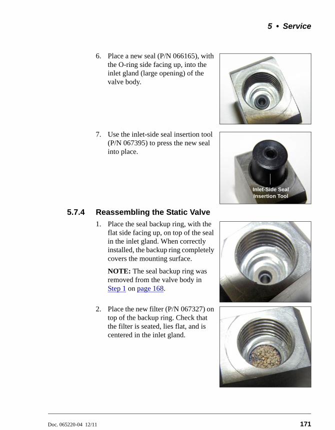
5 • Service
Doc. 065220-04 12/11 171
6. Place a new seal (P/N 066165), with the O-ring side facing up, into the inlet gland (large opening) of the valve body.
7. Use the inlet-side seal insertion tool (P/N 067395) to press the new seal into place.
5.7.4 Reassembling the Static Valve
1. Place the seal backup ring, with the flat side facing up, on top of the seal in the inlet gland. When correctly installed, the backup ring completely covers the mounting surface.
NOTE: The seal backup ring was removed from the valve body in Step 1 on page 168.
2. Place the new filter (P/N 067327) on top of the backup ring. Check that the filter is seated, lies flat, and is centered in the inlet gland.
Inlet-Side Seal Insertion Tool
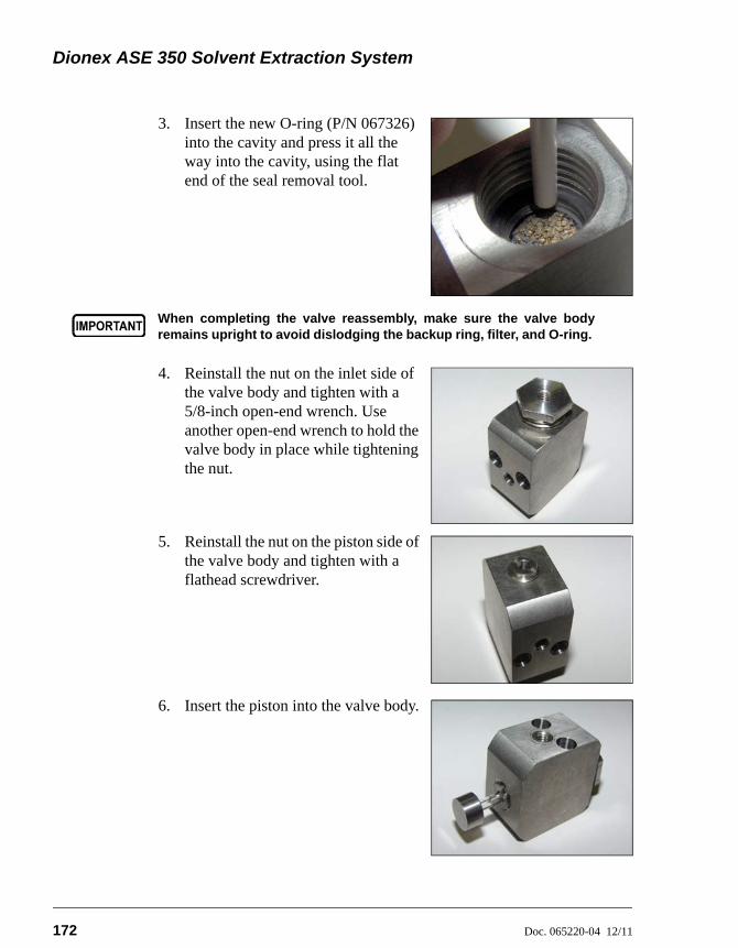
Dionex ASE 350 Solvent Extraction System
172 Doc. 065220-04 12/11
3. Insert the new O-ring (P/N 067326) into the cavity and press it all the way into the cavity, using the flat end of the seal removal tool.
4. Reinstall the nut on the inlet side of the valve body and tighten with a 5/8-inch open-end wrench. Use another open-end wrench to hold the valve body in place while tightening the nut.
5. Reinstall the nut on the piston side of the valve body and tighten with a flathead screwdriver.
6. Insert the piston into the valve body.
When completing the valve reassembly, make sure the valve bodyremains upright to avoid dislodging the backup ring, filter, and O-ring.

5 • Service
Doc. 065220-04 12/11 173
7. Slide the piston ferrule onto the piston holder at the end of the cylinder.
8. Replace the two mounting screws in the valve body and screw them lightly into the valve body to secure the body to the base plate. Do not fully tighten the screws yet.
9. Slide the spacer tool (P/N 068118) between the valve body and the piston ferrule.
10. Screw the push screw tool (P/N 068119) into the opening in the end of the alignment tool (P/N 068117).
Piston Holder
Piston Ferrule
Spacer Tool
Alignment Tool
Push Screw Tool
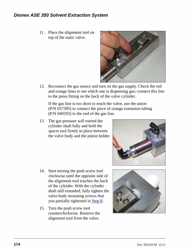
Dionex ASE 350 Solvent Extraction System
174 Doc. 065220-04 12/11
11. Place the alignment tool on top of the static valve.
12. Reconnect the gas source and turn on the gas supply. Check the red and orange lines to see which one is dispensing gas; connect this line to the press fitting on the back of the valve cylinder.
If the gas line is too short to reach the valve, use the union (P/N 057395) to connect the piece of orange extension tubing (P/N 049293) to the end of the gas line.
13. The gas pressure will extend the cylinder shaft fully and hold the spacer tool firmly in place between the valve body and the piston holder.
14. Start turning the push screw tool clockwise until the opposite side of the alignment tool touches the back of the cylinder. With the cylinder shaft still extended, fully tighten the valve body mounting screws that you partially tightened in Step 8.
15. Turn the push screw tool counterclockwise. Remove the alignment tool from the valve.

5 • Service
Doc. 065220-04 12/11 175
16. Turn off the gas supply and disconnect the gas line from the valve. Remove the orange extension tubing, if used.
17. Slide the cylinder shaft toward the cylinder. Remove the spacer tool from between the valve body and the piston ferrule.
5.7.5 Reinstalling the Static Valve
1. Reattach the static valve to the Dionex ASE 350, using the four mounting screws removed in Section 5.7.1. Use a 2.5-mm hex wrench to tighten the screws. Tighten until the screw head touches the rubber bumper on the mounting bracket and then turn an additional one-half turn. Do not overtighten!
2. Reconnect all fluid and gas connections to the static valve.
3. Follow the steps below to test the system for leaks:
a. Install one of the following in the cell tray: a “blank” sample cell of any size filled with Ottawa sand (Fisher S23-3) or an empty sample cell with a volume of less than 34 mL. (A “blank” cell contains no sample.)
b. Install a collection vessel in position 1 of the collection tray.
c. Check that the waste bottle is installed.
d. Press Menu to display the MAIN MENU OF SCREENS and press 3 to display the METHOD EDITOR screen.
e. Create a method with the following values:
TEMPERATURE 0 °C
STATIC TIME 1 min
CYCLES 1
RINSE VOLUME 0%
PURGE 60 s (If the test solvent is water, set the purge time to 120 s.)
SOLVENT A 1
SOLVENT B 0
SOLVENT C 0
CELL TYPE SST
SOLVENT SAVER OFF

Dionex ASE 350 Solvent Extraction System
176 Doc. 065220-04 12/11
f. When you finish selecting parameters, save the method.
g. Press Menu to return to the MAIN MENU OF SCREENS and press 1 to display the LOAD METHOD/SEQUENCE screen.
h. Verify that METHOD appears in the LOAD field. If it does not, press Select to toggle to METHOD.
i. Move the cursor to the NUMBER field and enter the number of the method you created for the leak test. Press Enter or a cursor arrow.
j. Move the cursor to the BTL/VIAL # field, press 1, and press Enter. This closes the LOAD METHOD/SEQUENCE screen and opens the SYSTEM STATUS screen.
k. Press Start to begin the run.
l. During the static cycle, check the 5/8-inch nut connection on the inlet side of the valve body for leaks. If there is a leak, use a 5/8-inch open-end wrench to tighten the connection. Use another wrench to hold the valve body in place while tightening the nut.
During the static cycle, also check the tip of the source needle (the needle with the smaller diameter, near the front of the needle assembly) in the collection vessel. If liquid drips from the source needle into the collection vessel during the static cycle (when the static valve should be closed), it indicates that the valve was not rebuilt correctly. Press STOP to stop the run (or wait for the method to finish) and then reassemble the valve correctly.
m. When the system passes the leak test, go on to Step 4.
4. Gently feed the drain tubing connected to the upper drip tray through the hole in the side wall and back into the service area. Replace the three screws that hold the drip tray in place under the cell tray.
NOTE The drain tube is attached to the drip tray via abarbed fitting. Be careful not to break the barbor kink the drain tube.
5. Replace the tie wrap removed from the tubing underneath the drip tray (see Figure 5-20) with a new tie wrap (P/N 013331).
5 • Service
Doc. 065220-04 12/11 177
6. Reinstall the safety shield.
7. Reset the STATIC TOTAL CYCLE and STATIC SEAL CYCLES counters on the front panel USAGE LOG screen (see Section C.4).
– or –
If the Dionex ASE 350 is running under Chromeleon control, contact Thermo Fisher Scientific to reset the TotalStaticValveCycle and TotalStaticValveSealCycle counters on the Wellness panel (see Section 2.5.3).

Dionex ASE 350 Solvent Extraction System
178 Doc. 065220-04 12/11
5.8 Replacing the Source Needle
1. Turn off the Dionex ASE 350 power switch.
2. Disconnect the compressed air or nitrogen gas connections at the Dionex ASE 350 rear panel. (This allows you to move the needle assembly manually.)
3. Open the safety shield.
4. Remove the collection bottles from the tray. With the needle assembly positioned over the outside row of the tray, push the needle assembly down.
5. Use a 2.5-mm hex wrench to remove the two screws on the top of the needle block (see Figure 5-23).
Figure 5-23. Removing the Needle Block Screws
6. Slide the cover of the needle block to the front and right, away from the needle (see Figure 5-24). Remove the cover.
Figure 5-24. Removing the Needle Block Cover
Remove these screws
NeedleBlock
Needle BlockCover
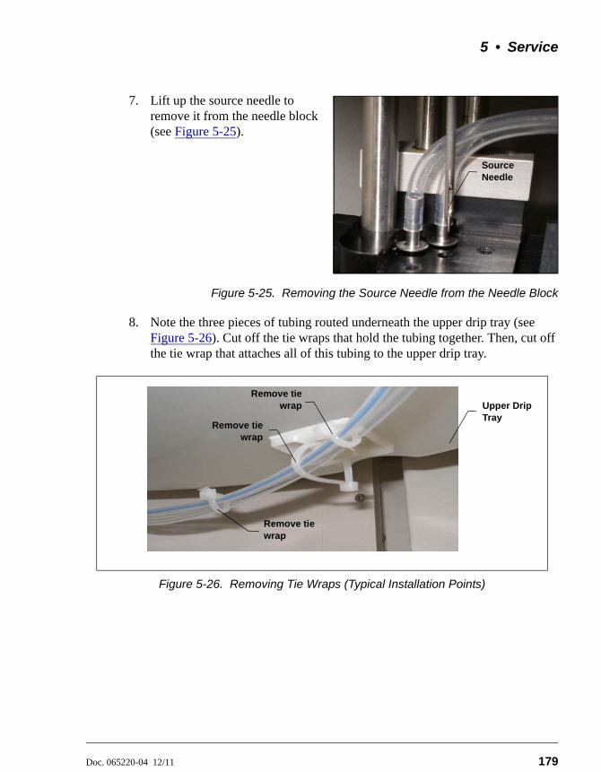
5 • Service
Doc. 065220-04 12/11 179
7. Lift up the source needle to remove it from the needle block (see Figure 5-25).
Figure 5-25. Removing the Source Needle from the Needle Block
8. Note the three pieces of tubing routed underneath the upper drip tray (see Figure 5-26). Cut off the tie wraps that hold the tubing together. Then, cut off the tie wrap that attaches all of this tubing to the upper drip tray.
Figure 5-26. Removing Tie Wraps (Typical Installation Points)
Source Needle
Upper Drip Tray
Remove tiewrap
Remove tie wrap
Remove tiewrap
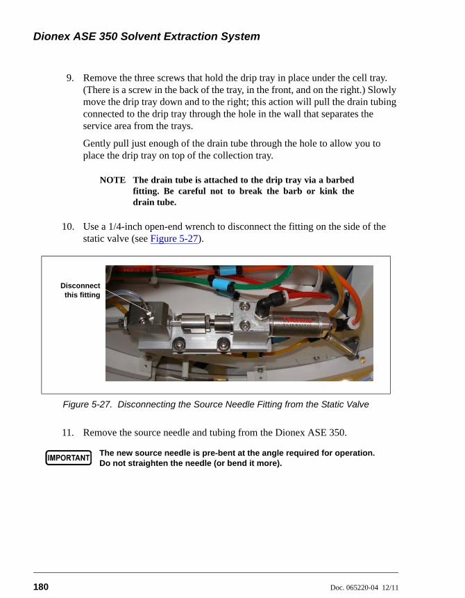
Dionex ASE 350 Solvent Extraction System
180 Doc. 065220-04 12/11
9. Remove the three screws that hold the drip tray in place under the cell tray. (There is a screw in the back of the tray, in the front, and on the right.) Slowly move the drip tray down and to the right; this action will pull the drain tubing connected to the drip tray through the hole in the wall that separates the service area from the trays.
Gently pull just enough of the drain tube through the hole to allow you to place the drip tray on top of the collection tray.
NOTE The drain tube is attached to the drip tray via a barbedfitting. Be careful not to break the barb or kink thedrain tube.
10. Use a 1/4-inch open-end wrench to disconnect the fitting on the side of the static valve (see Figure 5-27).
11. Remove the source needle and tubing from the Dionex ASE 350.
Figure 5-27. Disconnecting the Source Needle Fitting from the Static Valve
The new source needle is pre-bent at the angle required for operation.Do not straighten the needle (or bend it more).
Disconnectthis fitting

5 • Service
Doc. 065220-04 12/11 181
12. Insert the new source needle assembly (P/N 068955) into the middle opening in the needle block (see Figure 5-28) just until the washer meets the top surface.
Figure 5-28. Installing the New Source Needle
13. Replace the cover on the needle block and reinstall the two screws.
14. Connect the free end of the source needle tubing to the side of the static valve.
15. Gently feed the drain tubing connected to the upper drip tray through the hole in the side wall and back into the service area. Replace the three screws that hold the drip tray in place under the cell tray.
NOTE The drain tube is attached to the drip tray via a barbedfitting. Be careful not to break the barb or kink thedrain tube.
16. Locate the tie wraps (P/N 013331) provided in the Dionex ASE 350 Ship Kit (P/N 066060). Install new tie wraps to support the three pieces of tubing.
17. Install an additional tie wrap to attach the pieces of tubing to the upper drip tray. Leave some slack in this tie wrap (see Figure 5-26).
18. Reconnect the gas and air sources at the Dionex ASE 350 rear panel. Turn on the gas and air supplies.
19. Turn on the Dionex ASE 350 power switch.
Source Needle

Dionex ASE 350 Solvent Extraction System
182 Doc. 065220-04 12/11
5.9 Replacing the Hydrocarbon Sensor
A failed (or failing) hydrocarbon sensor can have reduced sensitivity.
1. Turn off the gas and air supplies. Disconnect the gas and air sources at the Dionex ASE 350 rear panel.
2. Turn off the Dionex ASE 350 power switch. Disconnect the power cord from both its source and the Dionex ASE 350 right-side panel.
3. Use a #1 Phillips screwdriver to remove all of the screws in the rear cover of the Dionex ASE 350. Remove the rear cover and set it aside.
4. The hydrocarbon sensor (see Figure 5-29, ) is installed in the upper right
corner, behind the fan ( ).
HIGH VOLTAGE—Disconnect the main power cord from its source, aswell as from the right-side panel of the Dionex ASE 350.
HAUTE TENSION—Débranchez le cordon d'alimentation principal dupanneau latéral droit de l’Dionex ASE 350.
HOCHSPANNUNG—Ziehen Sie das Netzkabel aus der Steckdose undder Netzbuchse auf der rechten Seite des Dionex ASE 350.
Figure 5-29. Hydrocarbon Sensor
11
22
Hydrocarbon Sensor
Sensor Socket
Fan2
3
1
1
2
3

5 • Service
Doc. 065220-04 12/11 183
5. The sensor is plugged into a socket ( ) that is connected to an electrical cable. To remove the sensor from the socket, wiggle it and gently pull it out of the socket.
6. Plug the new hydrocarbon sensor (P/N 938914) into the socket.
7. Replace the rear cover of the Dionex ASE 350.
8. Reconnect the gas and air sources at the Dionex ASE 350 rear panel. Turn on the gas and air supplies.
9. Reconnect the main power cord and turn on the Dionex ASE 350 power switch.
10. Thermo Fisher Scientific recommends equilibrating the sensor overnight. If this is not possible, wait at least two hours for the signal to stabilize before resuming operation.
33

Dionex ASE 350 Solvent Extraction System
184 Doc. 065220-04 12/11
5.10 Replacing the Main Power Fuses
1. Turn off the Dionex ASE 350 power switch. Disconnect the power cord from both its source and from the Dionex ASE 350 right-side panel.
2. The fuse drawer is located above the main power switch (see Figure 5-30). A small tab locks the fuse drawer in place. Using a small screwdriver, press the tab in and then up to release the fuse drawer.
3. Pull the fuse drawer out of the rear panel and remove the old fuses. Thermo Fisher Scientific recommends always replacing both fuses.
4. Insert two new 10 amp IEC127 fast-blow fuses (P/N 954746) into both of the springs in the fuse drawer. Press gently to fully insert the fuses into the drawer.
Figure 5-30. Fuse Drawer
5. Insert the fuse drawer into the right-side panel and press until the drawer snaps into place.
6. Reconnect the main power cord and turn on the Dionex ASE 350 power switch.
HIGH VOLTAGE—Disconnect the main power cord from its source, aswell as from the right-side panel of the Dionex ASE 350.
HAUTE TENSION—Débranchez le cordon d'alimentation principal desa source et du panneau latéral droit de l’Dionex ASE 350.
HOCHSPANNUNG—Ziehen Sie das Netzkabel aus der Steckdose undder Netzbuchse auf der rechten Seite des Dionex ASE 350.
Fuse Drawer
Main Power Switch
Tab
Doc. 065220-04 12/11 185
A • Specifications
A.1 Electrical
A.2 Environmental
PowerRecommendations
100 to 120 Vac or 220 to 240 Vac, 50/60 Hz. The Dionex ASE 350 main power supply is auto-sensing and requires no voltage or frequency adjustment.
Power Limitations The Dionex ASE 350 is functional at a low of 90 Vac and a high of 264 Vac.
Typical OperatingPower
500 W
MaximumOperating Power
1000 W
Maximum LineDraw
8 A at 110 Vac
Oven PowerRequirements
Two switches set the oven voltage to 110 (for voltages between 100 and 120 Vac) or 220 (for voltages between 220 and 240 Vac).
FuseRequirements
Two IEC127 fast-blow fuses (P/N 954746) rated at 10 A
OperatingTemperature
4 to 40 °C (39.2 to 104 °F)Note: The Dionex ASE 350 is intended for operation indoors only.
OperatingHumidity
5% to 95% relative humidity (noncondensing)

Dionex ASE 350 Solvent Extraction System
186 Doc. 065220-04 12/11
A.3 Physical
A.4 Pneumatic
A.5 Display and Keypad
A.6 Sample Cells and Tray
Dimensions Height: 69.3 cm (27.3 in)Width: 67.3 cm (26.5 in)Depth: 61.7 cm (24.3 in)
Weight 65 kg (140 lb)
Laboratory Air 0.41 to 1.38 MPa (60 to 200 psi)
Nitrogen 0.97 to 1.38 MPa (140 to 200 psi)
Display Liquid crystal with adjustable contrast
Keypad 26-button keypad for entering commands and programming methods and sequences
Stainless SteelSample Cells
Stainless steel cell bodies and end caps with PEEK seals and stainless steel frits. Cells are available in the following sizes:
• 1 mL (actual volume: 1.0 mL)
• 5 mL (actual volume: 5.0 mL)
• 10 mL (actual volume: 10.0 mL)
• 22 mL (actual volume: 22.0 mL)
• 34 mL (actual volume: 34.0 mL)
• 66 mL (actual volume: 66.0 mL)
• 100 mL (actual volume: 99.8 mL)
Zirconium SampleCells
Zirconium cell bodies and end caps with PEEK seals and zirconium frits. Cells are available in the following sizes:
• 66 mL (actual volume: 66.0 mL)
• 100 mL (actual volume: 99.8 mL)

A • Specifications
Doc. 065220-04 12/11 187
A.7 Collection Vessels and Tray
A.8 Interior Components
Cell Tray 24 sample cell positions and 2 rinse positions
Collection Bottles 250-mL bottle; the bottle septum is PTFE-coated on the solvent side
Collection Vials 60-mL vial; the vial septum is PTFE-coated on the solvent side
Collection Tray Holds up to 14 collection bottles on the outside row, plus five collection bottles and two rinse bottles on the inside row.When a vial tray insert (P/N 066176) is installed: Holds up to 28 60-mL collection vials on the outside row, plus five 250-mL collection bottles and two rinse bottles on the inside row.
Oven Accommodates one cell at a time in a vertical position. Heats from 40 to 200 °C (104 to 392 °F); shuts off automatically after four hours of no system activity, provided that no method or sequence is running.
Pump Operating pressure of 10.34 MPa (1500 psi)
Valves High-pressure valves: pressure relief and staticLow-pressure valves: purge, prime, and pneumatics
Collection VesselSensors
Sensors for detecting collection vessels present and full
Leak Sensors Sensors for detecting hydrocarbon vapor and liquid leaks
Cell Sensors Sensors for detecting cell size

Dionex ASE 350 Solvent Extraction System
188 Doc. 065220-04 12/11

Doc. 065220-04 12/11 189
B • Installation
B.1 Facility Requirements
Provide the following installation site facilities for the Thermo Scientific Dionex ASE 350 Accelerated Solvent Extractor:
• A sturdy table or workbench in a location that minimizes Dionex ASE 350 exposure to direct sunlight.
• A source of laboratory compressed air, regulated to between 0.41 and 1.38 MPa (60 and 200 psi); 0.69 (100 psi) is recommended. If compressed air is unavailable, substitute nitrogen (see Section B.3).
• A source of 99.9% pure nitrogen gas, regulated to between 0.97 and 1.38 MPa (140 and 200 psi); 1.03 MPa (150 psi) is recommended. Ultra-high purity (UHP) gas may be required for applications that require a very clean baseline from an electron capture detector (ECD).
• A grounded, single-phase power source of 100 to 240 Vac, 50/60 Hz. The oven voltage switch settings must match the voltage at the installation site: 110 (for voltages between 100 and 120 Vac) or 220 (for voltages between 220 and 240 Vac). For details, see Section B.4.
Use caution when lifting the Dionex ASE 350. Two or more personsshould lift the module, which weighs 65 kg (140 lb). Lift only from thebottom surface.
Soyez prudent lorsque vous soulevez l'Dionex ASE 350. Au moinsdeux personnes devraient soulever le module qui pèse 65 kg.Soulevez seulement du fond.
Seien Sie vorsichtig, wenn Sie den Dionex ASE 350 anheben. DasGerät wiegt 65 kg. Wenn Sie den Dionex ASE 350 anheben oderbewegen möchten, greifen Sie bitte immer unter den Boden.

ASE 350 Solvent Extraction System
190 Doc. 065220-04 12/11
B.2 Getting Ready to Install the Dionex ASE 350
Before beginning the installation procedure, check that the Dionex ASE 350 Ship Kit (P/N 066060) is on hand. Also locate the Dionex ASE 350 Startup Kit and verify that it is appropriate for the cell size you plan to use (see below). Both kits contain several items that are needed to install the system.
Small Volume Startup Kit
The Small Volume Startup Kit (P/N 068254) is for use with the following sample cell sizes: 1 mL, 5 mL, 10 mL, and 22 mL.
34-mL Volume Startup Kit
The 34-mL Volume Startup Kit (P/N 068255) is for use with 34-mL sample cells only.
Part Number Item Quantity
048784 Collection vials, 60 mL Pkg. 72
049482 Cell End Cap PTFE O-Ring Kit Pkg. 10
061687 PEEK seals Pkg. 50
066176 Vial tray insert 1
068075 Sample funnel, 5 to 22 mL 1
068076 Sample funnel, 1 mL 1
068093 Cellulose filters, 27 mm Pkg. 100
Table B-1. Dionex ASE 350 Small Volume Startup Kit Contents
Part Number Item Quantity
048784 Collection vials, 60 mL Pkg. 72
049482 Cell End Cap PTFE O-Ring Kit Pkg. 10
056780 Cellulose filters, 30 mm Pkg. 100
061687 PEEK seals Pkg. 50
066176 Vial tray insert 1
056699 Sample funnel, 34 to 100 mL 1
Table B-2. Dionex ASE 350 34-mL Volume Startup Kit Contents
B • Installation
Doc. 065220-04 12/11 191
Large Volume Startup Kit
The Large Volume Startup Kit (P/N 068256) is for use with the following sample cell sizes: 66 mL and 100 mL.
B.3 Connecting the Air/Nitrogen Sources
This section contains two installation procedures:
• To connect compressed air and nitrogen gas sources to the Dionex ASE 350, follow the procedure that starts on page 191.
• To configure the system when compressed air is not available, follow the procedure that starts on page 193.
Compressed Air and Nitrogen Connections
Refer to Figure B-1 when making air and nitrogen connections.
1. Connect the 6-mm (0.25-in) elbow fitting (P/N 214738) to the regulator on the compressed air source.
Part Number Item Quantity
049482 Cell End Cap PTFE O-Ring Kit Pkg. 10
056284 Collection bottles, 250 mL Pkg. 12
056780 Cellulose filters, 30 mm Pkg. 100
061687 PEEK seals Pkg. 50
056699 Sample funnel, 34 to 100 mL 1
Table B-3. Dionex ASE 350 Large Volume Start-Up Kit Contents
The air and nitrogen connections on the Dionex ASE 350 rear panel (see Figure B-1) are press fittings.
• To connect a press fitting, firmly push the tubing into the fitting until it is seated.
• To disconnect a press fitting, use your fingers (or a small open-end wrench) to press the ring on the fitting in, while at the same time pulling the tubing out.

ASE 350 Solvent Extraction System
192 Doc. 065220-04 12/11
2. Push one end of the yellow 6-mm (0.25-in) OD tubing (P/N 214739) into the 6-mm (0.25-in) elbow fitting; connect the other end to the inlet filter assembly (P/N 049492).
3. Check that the arrow on the filter points in the direction of the air flow (toward the Dionex ASE 350). Push the tubing on the other end of the filter assembly into the AIR connector on the Dionex ASE 350 rear panel.
4. Adjust the compressed air pressure source to between 0.41 and 1.38 MPa (60 and 200 psi); 0.69 MPa (100 psi) is recommended.
5. Connect the 4-mm (0.156-in) elbow fitting (P/N 049272) to the regulator on the nitrogen gas source.
6. Push one end of the blue 4-mm (0.156-in) OD tubing (P/N 049296) into the 4-mm (0.156-in) elbow fitting; push the other end into the NITROGEN connector on the Dionex ASE 350 rear panel.
7. Adjust the nitrogen pressure source to between 0.97 and 1.38 MPa (140 and 200 psi); 1.03 MPa (150 psi) is recommended.
Figure B-1. Dionex ASE 350 Rear Panel Connections
8-mm (0.312-in) ODClear Tubing (P/N 053514)
6-mm (0.25-in) OD Yellow Tubing (P/N 214739)
4-mm (0.156-in) ODBlue Tubing (P/N 049296)
0.97 to 1.38 MPa(140 to 200 psi)
0.41 to 1.38 MPa(60 to 200 psi)
ASE 350 Rear Panel
6-mm (0.25-in) Elbow Fitting (P/N 214738)
4-mm (0.156-in) Elbow Fitting(P/N 049272)
Inlet Filter Assembly(P/N 049492)
AIR
N2
AIRNITROGEN
VENT
WARNING! Do not obstruct or pressurize the VENT outlet.

B • Installation
Doc. 065220-04 12/11 193
8. Push one end of the 3.05-meter (10-ft) section of clear 8-mm (0.312-in) OD tubing (P/N 053514) into the VENT connector on the Dionex ASE 350 rear panel (see Figure B-1).
9. (Optional) Route the tubing from the VENT connector to a fume hood.
10. Push one end of the clear corrugated drain hose (P/N 055075) on to the drip tray drain port on the Dionex ASE 350 rear panel (see Figure 2-7). If necessary, use a hose clamp (P/N 067402) to attach the hose to the drain port.
11. Place the free end of the drain hose into a waste container. To maintain a positive siphon, position the waste container below the level of the Dionex ASE 350.
Pump Ship Kit Part Number
Substituting Nitrogen for Compressed Air
This section describes how to connect the nitrogen gas source to the NITROGEN and AIR connectors on the Dionex ASE 350 rear panel. Refer to Figure B-2 when making these connections.
1. Connect the yellow 6-mm (0.25-in) OD tubing end of the air/nitrogen tee assembly (P/N 049680) to the AIR connector on the Dionex ASE 350 rear panel.
Make sure the vent tubing runs downhill from the Dionex ASE 350 rearpanel. This prevents formation of a trap, which would prevent vaporsfrom being vented through the tubing.
Do not obstruct or pressurize the vent outlet.
Ne bouchez ni ne mettez sous pression la sortie d'aération.
Halten Sie den Lüftungsauslaß frei, setzen Sie ihn nicht unter Druck.
For correct drainage, make sure the drain hose is not bent, pinched,or elevated at any point. Do not allow the end of the drain hose to besubmerged in waste liquid.
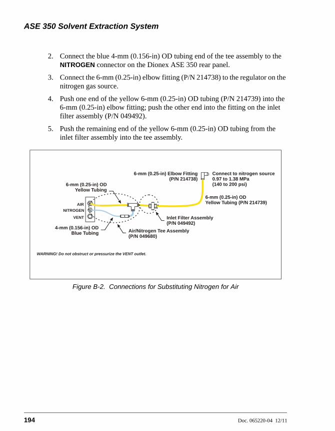
ASE 350 Solvent Extraction System
194 Doc. 065220-04 12/11
2. Connect the blue 4-mm (0.156-in) OD tubing end of the tee assembly to the NITROGEN connector on the Dionex ASE 350 rear panel.
3. Connect the 6-mm (0.25-in) elbow fitting (P/N 214738) to the regulator on the nitrogen gas source.
4. Push one end of the yellow 6-mm (0.25-in) OD tubing (P/N 214739) into the 6-mm (0.25-in) elbow fitting; push the other end into the fitting on the inlet filter assembly (P/N 049492).
5. Push the remaining end of the yellow 6-mm (0.25-in) OD tubing from the inlet filter assembly into the tee assembly.
Figure B-2. Connections for Substituting Nitrogen for Air
6-mm (0.25-in) OD Yellow Tubing (P/N 214739)
Connect to nitrogen source0.97 to 1.38 MPa (140 to 200 psi)6-mm (0.25-in) OD
Yellow Tubing
6-mm (0.25-in) Elbow Fitting(P/N 214738)
4-mm (0.156-in) ODBlue Tubing Air/Nitrogen Tee Assembly
(P/N 049680)
Inlet Filter Assembly(P/N 049492)
AIR
NITROGEN
VENT
WARNING! Do not obstruct or pressurize the VENT outlet.
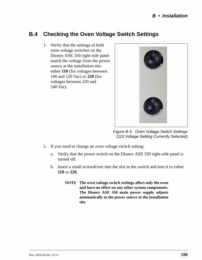
B • Installation
Doc. 065220-04 12/11 195
B.4 Checking the Oven Voltage Switch Settings
1. Verify that the settings of both oven voltage switches on the Dionex ASE 350 right-side panel match the voltage from the power source at the installation site: either 110 (for voltages between 100 and 120 Vac) or 220 (for voltages between 220 and 240 Vac).
Figure B-3. Oven Voltage Switch Settings(110 Voltage Setting Currently Selected)
2. If you need to change an oven voltage switch setting:
a. Verify that the power switch on the Dionex ASE 350 right-side panel is turned off.
b. Insert a small screwdriver into the slot in the switch and turn it to either 110 or 220.
NOTE The oven voltage switch settings affect only the ovenand have no effect on any other system components.The Dionex ASE 350 main power supply adjustsautomatically to the power source at the installationsite.
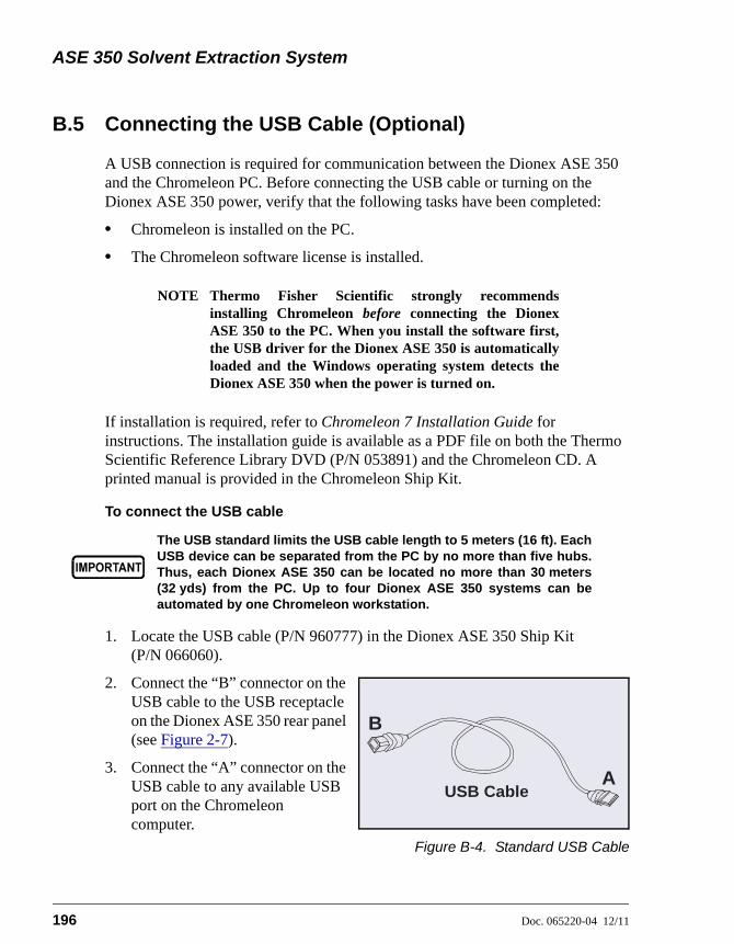
ASE 350 Solvent Extraction System
196 Doc. 065220-04 12/11
B.5 Connecting the USB Cable (Optional)
A USB connection is required for communication between the Dionex ASE 350 and the Chromeleon PC. Before connecting the USB cable or turning on the Dionex ASE 350 power, verify that the following tasks have been completed:
• Chromeleon is installed on the PC.
• The Chromeleon software license is installed.
NOTE Thermo Fisher Scientific strongly recommendsinstalling Chromeleon before connecting the DionexASE 350 to the PC. When you install the software first,the USB driver for the Dionex ASE 350 is automaticallyloaded and the Windows operating system detects theDionex ASE 350 when the power is turned on.
If installation is required, refer to Chromeleon 7 Installation Guide for instructions. The installation guide is available as a PDF file on both the Thermo Scientific Reference Library DVD (P/N 053891) and the Chromeleon CD. A printed manual is provided in the Chromeleon Ship Kit.
To connect the USB cable
1. Locate the USB cable (P/N 960777) in the Dionex ASE 350 Ship Kit (P/N 066060).
2. Connect the “B” connector on the USB cable to the USB receptacle on the Dionex ASE 350 rear panel (see Figure 2-7).
3. Connect the “A” connector on the USB cable to any available USB port on the Chromeleon computer.
Figure B-4. Standard USB Cable
The USB standard limits the USB cable length to 5 meters (16 ft). EachUSB device can be separated from the PC by no more than five hubs.Thus, each Dionex ASE 350 can be located no more than 30 meters(32 yds) from the PC. Up to four Dionex ASE 350 systems can beautomated by one Chromeleon workstation.
USB CableA
B

B • Installation
Doc. 065220-04 12/11 197
B.6 Connecting the Power Cord
1. Verify that the power switch on the Dionex ASE 350 right-side panel (see Figure 2-6) is turned off.
2. Connect a modular power cord (IEC 320 C13) from the main power receptacle on the Dionex ASE 350 right-side panel to a grounded, single-phase power source of 100 to 240 Vac, 50/60 Hz.
SHOCK HAZARD—To avoid electrical shock, a grounded receptaclemust be used. Do not operate the Dionex ASE 350 or connect it to ACpower mains without an earthed ground connection.
The power supply cord is used as the main disconnect device. Makesure the socket-outlet is located near the Dionex ASE 350 and iseasily accessible.
Operation at AC input levels outside of the specified operating voltagerange may damage the Dionex ASE 350.
DANGER D'ÉLECTROCUTION—Pour éviter toute électrocution, il faututiliser une prise de courant avec prise de terre. Ne l'utilisez pas et nele branchez pas au secteur C.A. sans utiliser de branchement mis à laterre.
Le cordon d'alimentation principal est utilisé comme dispositifprincipal de débranchement. Veillez à ce que la prise de base soitsituée/installée près du module et facilement accessible.
STROMSCHLAGGEFAHR—Zur Vermeidung von elektrischenSchlägen ist eine geerdete Steckdose zu verwenden. Das Gerät darfnicht ohne Erdung betrieben bzw. an Wechselstrom angeschlossenwerden.
Das Netzkabel ist das wichtigste Mittel zur Stromunterbrechung.Stellen Sie sicher, daß sich die Steckdose nahe am Gerät befindet undleicht zugänglich ist.
ASE 350 Solvent Extraction System
198 Doc. 065220-04 12/11
B.7 Setting Up Chromeleon (Optional)
When you start the Dionex ASE 350 after connecting to the PC, the PC detects the presence of the new USB device. You can then create a new “instrument” and add the Dionex ASE 350 to it. (In Chromeleon, an instrument consists of all modules that are combined in a single chromatography system to enable chromatographic separations. For extractions, each Dionex ASE 350 must be configured as a different instrument.)
Up to four Dionex ASE 350 systems (each configured as a different instrument) can be automated by one Chromeleon workstation. Systems are configured in the Chromeleon Instrument Configuration program. Refer to Chromeleon 7 Installation Guide or the Chromeleon Help for detailed instructions.
Create a New Instrument in Chromeleon
1. Turn on the computer power and log onto Windows Vista or Windows XP as an administrator.
2. Right-click the Chromeleon tray icon in the notification area of the Windows taskbar, and click Show Chromeleon Services Manager.
3. In the Chromeleon Services Manager, click Start Instrument Controller.
4. Right-click the Chromeleon tray icon, and click Configure instruments to start the Instrument Configuration program.
5. Right-click a PC icon in the left pane of the Instrument Configuration program, and then click Add Instrument. If necessary, edit the default name in the New Instrument dialog box.
Add the Dionex ASE 350 to an Instrument
1. Right-click the name of the instrument in the Instrument Configuration program, and then click Add Module.
2. In the Add module to instrument dialog box, in the Manufacturers list under Dionex, select Extraction Modules. In the Modules list, select ASE 350 Accelerated Solvent Extractor. Click OK. The Properties dialog box will appear.
Configure the Dionex ASE 350
1. Chromeleon support requires Dionex ASE 350 firmware version 2.00.00 (or later). If necessary, download a new firmware version from the General tab page in the Properties dialog box:

B • Installation
Doc. 065220-04 12/11 199
a. Select the serial number of your Dionex ASE 350 in the Module Serial No. list.
b. Click Download, and then select the appropriate firmware file. The update can take several minutes. The update is complete when the related message appears in the Messages Instrument Controller window.
2. On the Options tab page (see below), specify the unit of measure for pressure displays and the default solvent names. If the vial tray insert is installed in the collection tray, select the Vial Tray Insert check box. When you finish selecting options, click OK.
3. On the File menu, click Save Installation and then close the Instrument Configuration program.
Connect to Chromeleon
1. To start the Chromeleon client, click Start > All Programs > Chromeleon 7 > Chromeleon 7.
2. To display the Dionex ASE 350 ePanel Set, click the Instruments Category Bar on the Console. Click your instrument in the Navigation Pane.

ASE 350 Solvent Extraction System
200 Doc. 065220-04 12/11
Chromeleon connects to the instrument and displays the ePanel Set (see Figure B-5).
3. Check the lower left corner of the system graphic on the Dionex ASE 350 ePanel: When the Dionex ASE 350 is connected to Chromeleon, a green button labeled Connected is displayed here. If you see a red button labeled Disconnected, click the button to connect the system to Chromeleon.
Figure B-5. Example Chromeleon Dionex ASE 350 ePanel
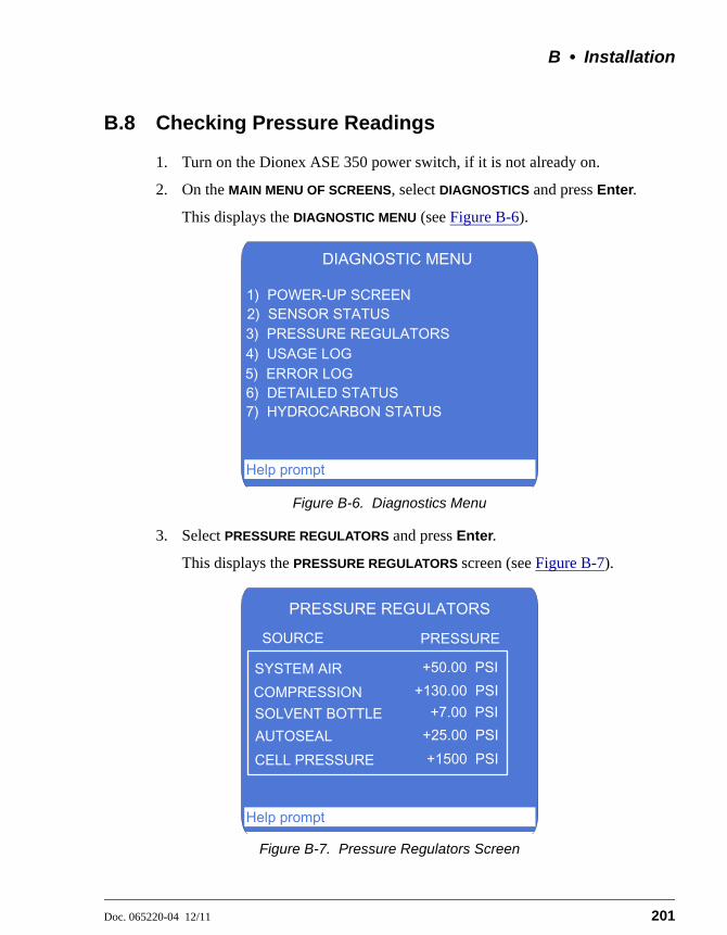
B • Installation
Doc. 065220-04 12/11 201
B.8 Checking Pressure Readings
1. Turn on the Dionex ASE 350 power switch, if it is not already on.
2. On the MAIN MENU OF SCREENS, select DIAGNOSTICS and press Enter.
This displays the DIAGNOSTIC MENU (see Figure B-6).
3. Select PRESSURE REGULATORS and press Enter.
This displays the PRESSURE REGULATORS screen (see Figure B-7).
Figure B-6. Diagnostics Menu
Figure B-7. Pressure Regulators Screen
DIAGNOSTIC MENU
3) PRESSURE REGULATORS4) USAGE LOG
1) POWER-UP SCREEN
5) ERROR LOG
2) SENSOR STATUS
6) DETAILED STATUS
Help prompt
7) HYDROCARBON STATUS
PRESSURE REGULATORS
SYSTEM AIR
PRESSURESOURCE
+50.00 PSI+130.00 PSI
+7.00 PSI+25.00 PSI+1500 PSI
COMPRESSIONSOLVENT BOTTLEAUTOSEALCELL PRESSURE
Help prompt

ASE 350 Solvent Extraction System
202 Doc. 065220-04 12/11
NOTE The COMPRESSION, AUTOSEAL, and CELL PRESSUREreadings are zero unless a run is in progress and a cell isin the oven.
4. Compare the pressure readings on the PRESSURE REGULATORS screen with the values listed in the table below. If a pressure reading does not meet specification, contact Thermo Fisher Scientific.
B.9 Connecting the Solvent Reservoirs
Field Function Pressure Spec
SYSTEM AIR Pressure applied to the system 0.34 MPa (50 3 psi)
COMPRESSION Pressure applied when the oven is compressed
0.90 0.03 MPa (130 5 psi)
SOLVENT BOTTLE
Pressure applied to the solvent reservoir
48.26 6.89 kPa (7 1 psi)
AUTOSEAL Pressure applied when the AutoSeal air cylinder is actuated
172.37 14 kPa (25 2 psi)
Use only Thermo Fisher Scientific solvent reservoirs. These are glassreservoirs with a plastic, shatterproof coating. To prevent personalinjury, make sure the pressure applied to the reservoirs does notexceed 0.07 MPa (10 psi).
Utilisez uniquement des réservoirs à solvant Thermo Fisher Scientific.Ce sont des réservoirs en verre à revêtement incassable en plastique.Veillez à ce que la pression exercée sur ces réservoirs ne dépasse pas0,07 MPa.
Verwenden Sie ausschließlich die Lösemittelbehälter von ThermoFisher Scientific. Dabei handelt es sich um Glasbehälter mit einersplittersicheren Plastikbeschichtung. Vergewissern Sie sich, daß derDruck, der auf die Behälter ausgeübt wird, 0,07 MPa nicht übersteigt.
Never fill the solvent reservoir or disconnect the tubing connectionsto the solvent and gas connectors (see Figure B-8) during a run orrinse cycle. At these times, the solvent reservoir is pressurized. If youremove the reservoir cap when the solvent reservoir is pressurized,the Dionex ASE 350 may not operate to specification.

B • Installation
Doc. 065220-04 12/11 203
1. Fill the solvent reservoir (P/N 045901) with prepared solvent (for example, acetone) to the level indicated in Figure B-8.
See Section 3.1.1 for information about selecting and preparing solvents.
The solvent level in the reservoir must remain below the gas line. Thisprevents solvent from coming into contact with the pneumatic valves.
Figure B-8. Solvent Reservoir Connections
End-Line Filter

ASE 350 Solvent Extraction System
204 Doc. 065220-04 12/11
2. Insert the solvent line extending from the underside of the reservoir cap assembly (P/N 068077) into the reservoir (see Figure B-8). Make sure the end-line filter rests on the bottom of the reservoir.
If necessary, loosen the fitting on top of the stopper, gently pull on the solvent line to bring more tubing into the reservoir, and then tighten the fitting.
3. Hand-tighten the gray lock ring cap securely over the stopper.
4. Set the reservoir in the recess reserved for solvent A in the solvent reservoir tray (see Figure B-9).
5. Screw the fitting on the solvent line into the SOLVENT connector closest to the bottle. Push the fitting on the gas line into the connector closest to the reservoir. (To disconnect the line, push the small latch at the top of the connector toward the center of the connector.)
NOTE Always connect the solvent line to the solvent connectorfirst, and then the gas line to the gas connector. Whendisconnecting the lines, first disconnect the gas line andthen the solvent line. This prevents inadvertentpressurization of the reservoir and solvent flow when itis not connected.
6. Follow the steps above to install additional reservoirs. Install the reservoirs in the locations indicated in Figure B-9. When proportioning solvents, the method will be programmed according to these positions.
Figure B-9. Location of Solvent Reservoirs
Solvent A
Solvent B
Solvent C
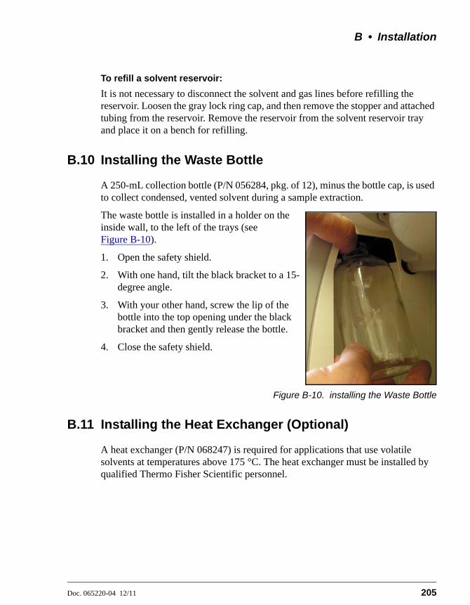
B • Installation
Doc. 065220-04 12/11 205
To refill a solvent reservoir:
It is not necessary to disconnect the solvent and gas lines before refilling the reservoir. Loosen the gray lock ring cap, and then remove the stopper and attached tubing from the reservoir. Remove the reservoir from the solvent reservoir tray and place it on a bench for refilling.
B.10 Installing the Waste Bottle
A 250-mL collection bottle (P/N 056284, pkg. of 12), minus the bottle cap, is used to collect condensed, vented solvent during a sample extraction.
The waste bottle is installed in a holder on the inside wall, to the left of the trays (see Figure B-10).
1. Open the safety shield.
2. With one hand, tilt the black bracket to a 15-degree angle.
3. With your other hand, screw the lip of the bottle into the top opening under the black bracket and then gently release the bottle.
4. Close the safety shield.
Figure B-10. installing the Waste Bottle
B.11 Installing the Heat Exchanger (Optional)
A heat exchanger (P/N 068247) is required for applications that use volatile solvents at temperatures above 175 °C. The heat exchanger must be installed by qualified Thermo Fisher Scientific personnel.

ASE 350 Solvent Extraction System
206 Doc. 065220-04 12/11
B.12 Inspecting the Cell and Rinse Tube
Before each run, inspect the O-rings installed in the exterior ends of each sample cell end cap and rinse tube (see Figure B-11).
PTFE O-rings (P/N 049482, pkg. of 10) are included in the Dionex ASE 350 Startup Kits. For dioxins and other high temperature applications, order Viton O-rings (P/N 056325, pkg. of 50).
• If an O-ring is dislodged, press it into place, using the O-ring insertion tool (P/N 049660) provided in the Dionex ASE 350 Ship Kit (P/N 066060).
Figure B-11. Inspecting Cell O-Rings
• If an O-ring is missing, place a new one over the opening in the end of the cell end cap. Press the O-ring into place, using the O-ring insertion tool (see Figure B-12).
• If an O-ring has a hole size of less than 0.5 mm, replace it. If a white PTFE O-ring is discolored, replace it.
Figure B-12. Installing a Cell End Cap O-Ring
Verify that O-ringsare installed andin good condition
O-Ring Insertion Tool(P/N 049660)
Place O-ring in openingand press into place with insertion tool.

B • Installation
Doc. 065220-04 12/11 207
B.13 Rinsing/Priming the System
1. Place rinse tubes in the rinse positions on the cell tray (between positions 6 and 7 and positions 18 and 19).
NOTE Always install rinse tubes in both positions.
2. Place collection vessels in positions R1 and R2 in the collection tray.
3. Close the safety shield.
4. Press the Menu button on the control panel keypad to display the MAIN MENU
OF SCREENS and press 5 to display the SYSTEM SETUP screen (see Figure B-13).
5. Press an arrow button to move the cursor to the RINSE VOLUME field. Enter the rinse volume and press Enter or a cursor arrow button.
6. Move the cursor to the RINSE CYCLES field. Select 2 and press Enter or a cursor arrow button. (Up to nine rinse cycles can be programmed.)
7. Press the RINSE button to start the manual rinse/prime cycle. During the cycle, the cell tray rotates to the nearest rinse tube, the collection tray rotates to a rinse position, and the selected amount of solvent is pumped through the system. This is followed by a 20-second nitrogen purge step.
Figure B-13. System Setup Screen
SYSTEM SETUP
RINSE VOLUME: 20 mL
PRESS UNITS: PSISOUND -- INPUT: NO ERROR: NO
LEAK ABORT: YES
PURGE VALVE: NO
MODE: LOCAL
PREHEAT: 12 MINCYCLES: 2
METHOD RINSE: NO
BYPASS HEATUP: NO
Help prompt

ASE 350 Solvent Extraction System
208 Doc. 065220-04 12/11
8. After the second rinse, the pump and the solvent line are primed. Remove the rinse bottles from the system, empty them, and place them in positions R1 and R2 in the collection tray.
To avoid personal injury, exercise caution whenever the tray is inmotion.
Pour éviter de vous blesser, faites bien attention lorsque le plateau esten mouvement.
Um Verletzungen vorzubeugen, seien Sie vorsichtig, wenn sich derProbenteller bewegt.
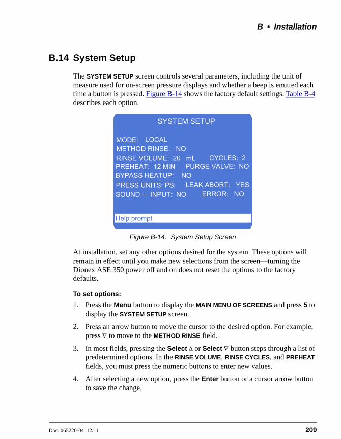
B • Installation
Doc. 065220-04 12/11 209
B.14 System Setup
The SYSTEM SETUP screen controls several parameters, including the unit of measure used for on-screen pressure displays and whether a beep is emitted each time a button is pressed. Figure B-14 shows the factory default settings. Table B-4 describes each option.
At installation, set any other options desired for the system. These options will remain in effect until you make new selections from the screen—turning the Dionex ASE 350 power off and on does not reset the options to the factory defaults.
To set options:
1. Press the Menu button to display the MAIN MENU OF SCREENS and press 5 to display the SYSTEM SETUP screen.
2. Press an arrow button to move the cursor to the desired option. For example, press to move to the METHOD RINSE field.
3. In most fields, pressing the Select or Select button steps through a list of predetermined options. In the RINSE VOLUME, RINSE CYCLES, and PREHEAT fields, you must press the numeric buttons to enter new values.
4. After selecting a new option, press the Enter button or a cursor arrow button to save the change.
Figure B-14. System Setup Screen
SYSTEM SETUP
RINSE VOLUME: 20 mL
PRESS UNITS: PSISOUND -- INPUT: NO ERROR: NO
LEAK ABORT: YES
PURGE VALVE: NO
MODE: LOCAL
PREHEAT: 12 MINCYCLES: 2
METHOD RINSE: NO
BYPASS HEATUP: NO
Help prompt

ASE 350 Solvent Extraction System
210 Doc. 065220-04 12/11
Option Description Values
MODE Displays the control mode. When the Dionex ASE 350 is powered up, it is always in Local mode. Remote mode is selected when you connect the Dionex ASE 350 to a Chromeleon ePanel. To return the Dionex ASE 350 to Local mode, click the Connected button on the ePanel (this toggles it to the Disconnected state) or turn off the Dionex ASE 350 power briefly.
LOCAL (default)REMOTE
METHOD RINSE Determines whether an automatic rinse is performed after each sample run during method control (see Section 3.1.10 for details).
NO (default)YES
RINSE VOLUME Specifies the volume of solvent pumped through the system in a single rinse operation. The selected volume will be used during both manual and automatic rinses.
0 to 99 mL (default=5 mL)
RINSE CYCLES Specifies the number of rinse cycles the system performs during a manual rinse.
1 through 9 (default=1)
PREHEAT Specifies for how long the cell is preheated before solvent is pumped into the cell.
0 to 99 min (default=0)
PURGE VALVE Determines whether the purge valve is open or closed during the preheat step. When the valve is open, purge gas flows through the cell.
NO (default) YES
Table B-4. System Setup Parameters
B • Installation
Doc. 065220-04 12/11 211
BYPASS HEATUP
Determines whether the initial heat-up step occurs. When NO is selected, the oven block is heated to ensure that the cell contents reach the set point during the heat-up step. All Thermo Scientific Dionex ASE Application Notes are based on this default setting; to obtain equivalent results, do not bypass the heat-up step.When YES is selected, the oven block is not heated; thus, the cell contents probably will not achieve the set point. Do not select this option unless you can achieve complete recovery of analytes without the additional heating.NOTE: The duration of the heat-up step depends on the method’s temperature set point; see Table 3-3 for details.
NO (default) YES
PRESS UNITS Specifies the unit of measure for pressure readings displayed on the Dionex ASE 350 front panel screen.
PSI (default) MPaATMBAR
LEAK ABORT Determines whether a run is aborted when a liquid leak is detected. When the default setting (NO) is selected, an error message appears, but the run continues.
NO (default) YES
INPUT SOUND Determines whether a beep is emitted when a keypad button is pushed.
NO (default) YES
ERROR SOUND Determines whether a beep is emitted when an error occurs (for example, you press the wrong keypad button).
NO (default) YES
Option Description Values
Table B-4. System Setup Parameters (Continued)

ASE 350 Solvent Extraction System
212 Doc. 065220-04 12/11

Doc. 065220-04 12/11 213
C • Diagnostic Screens
This appendix describes the Dionex ASE 350 diagnostic screens. To display the DIAGNOSTIC MENU, press 6 on the MAIN MENU OF SCREENS.
There are two ways to select a DIAGNOSTIC MENU option:
• Press the numeric button that corresponds to the screen name.
– or –
• Press an up or down arrow button to move the cursor to the screen name, and then press the Enter button.
Figure C-1. Diagnostic Menu
DIAGNOSTIC MENU
3) PRESSURE REGULATORS4) USAGE LOG
1) POWER-UP SCREEN
5) ERROR LOG
2) SENSOR STATUS
6) DETAILED STATUS
Help prompt
7) HYDROCARBON STATUS
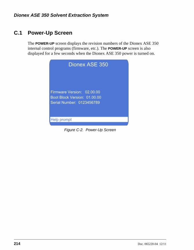
Dionex ASE 350 Solvent Extraction System
214 Doc. 065220-04 12/11
C.1 Power-Up Screen
The POWER-UP screen displays the revision numbers of the Dionex ASE 350 internal control programs (firmware, etc.). The POWER-UP screen is also displayed for a few seconds when the Dionex ASE 350 power is turned on.
Figure C-2. Power-Up Screen
Dionex ASE 350
Firmware Version: 02.00.00Boot Block Version: 01.00.00Serial Number: 0123456789
Help prompt

C • Diagnostic Screens
Doc. 065220-04 12/11 215
C.2 Sensor Status Screen
The SENSOR STATUS screen displays the status reported by various internal sensors. Screen entries are updated in real time at 2-second intervals. You cannot edit any information on the screen. This information is intended primarily to help Thermo Fisher Scientific Technical Support personnel troubleshoot operating problems with the system.
Not all of the status information can be displayed on the screen at once. To view more information, use the arrow up and down buttons to scroll through the list.
Figure C-3. Sensor Status Screen
Parameter Description
CELL SIZE The size of the cell in the oven (1, 5, 10, 22, 34, 66, or 100 mL), NO CELL (when no cell is in the oven), or A/S OPEN (when the AutoSeal arm is open, preventing detection of the cell size).
CELL TRAY HOME The cell tray location: YES (the tray is at the home position) or NO (the tray is not at the home position).
CELL TRAY POS The cell tray location: YES (the tray is at a cell position) or NO (the tray is not at a cell position).
A/S OUT TRAY The AutoSeal arm location: YES (the arm is at the cell tray) or NO (the arm is not at the cell tray).
SENSOR STATUS
A/S OUT TRAYA/S IN OVENA/S U/D TOP
CELL TRAY HOMECELL SIZE
A/S U/D CENTER
A/S OPENNO
YESNO
A/S U/D BOTTOM
CELL TRAY POS
Help prompt
YESOPENOPEN
BLOCKED
Dionex ASE 350 Solvent Extraction System
216 Doc. 065220-04 12/11
A/S IN OVEN The AutoSeal arm location: YES (the arm is in the oven) or NO (the arm is not in the oven).
A/S U/D TOP The top AutoSeal “up/down” sensor reading: OPEN or BLOCKED. This sensor works in conjunction with the A/S U/D CENTER and A/S U/D BOTTOM sensors. To identify the AutoSeal arm position, the status of all three sensors must be known.
A/S U/D CENTER The center AutoSeal “up/down” sensor reading: OPEN or BLOCKED. This sensor works in conjunction with the A/S U/D TOP and A/S U/D BOTTOM sensors. To identify the AutoSeal arm position, the status of all three sensors must be known.
A/S U/D BOTTOM The bottom AutoSeal arm “up/down” sensor reading: OPEN or BLOCKED. This sensor works in conjunction with the A/S U/D TOP and A/S U/D CENTER sensors. To identify the AutoSeal arm position, the status of all three sensors must be known.
A/S VALVE UP/DN The AutoSeal “up/down” pneumatic valve state: DN/ON (the valve is open) or UP/OFF (the valve is closed).
A/S VALVE IN The AutoSeal “in” pneumatic valve state: ON (the valve is open) or OFF (the valve is closed).
A/S VALVE OUT The AutoSeal “out” pneumatic valve state: ON (the valve is open) or OFF (the valve is closed).
BLT/VIAL PRESENT PRESENT (a collection vessel is present in this position) or NONE (no collection vessel is present in this position).
BOTTLE OR VIAL BOTTLE (no vial tray insert is detected) or VIAL (a vial tray insert is detected).
BOTTLE FULL The collection bottle in this tray position is FULL or NOT FULL.
VIAL FULL The collection vial in this tray position is FULL or NOT FULL.
VIAL TRAY HOME The collection tray location: YES (the tray is at the home position) or NO (the tray is not at the home position).

C • Diagnostic Screens
Doc. 065220-04 12/11 217
VIAL TRAY POS The collection tray location: YES (the tray is at a collection vessel position) or NO (the tray is not at a collection vessel position).
NEEDLE UP The “needle up” sensor reading: YES (the needle is up) or NO (the needle is not up).
NEEDLE DOWN The “needle down” sensor reading: YES (the needle is down) or NO (the needle is not down).
NEEDLE IN The “needle in” sensor reading: YES (the needle is at the inside row) or NO (the needle is not at the inside row).
NEEDLE OUT The “needle out” sensor reading: YES (the needle is at the outside row) or NO (the needle is not at the outside row).
NEEDLE VLV UP/DN The needle “up/down” pneumatic valve state: DN/ON (the valve is open) or UP/OFF (the valve is closed).
NEEDLE VLV IN The needle “in” pneumatic valve state: ON (the valve is open) or OFF (the valve is closed).
NEEDLE VLV OUT The needle “out” pneumatic valve state: ON (the valve is open) or OFF (the valve is closed).
SAFETY SHIELD The safety shield sensor reading: OPEN (the shield is open) or CLOSED (the shield is either closed or is not installed).
LIQUID LEAK The drip tray sensor reading: LEAK or NO LEAK.
HYDROCARBON The hydrocarbon concentration reading (0 to 4700).
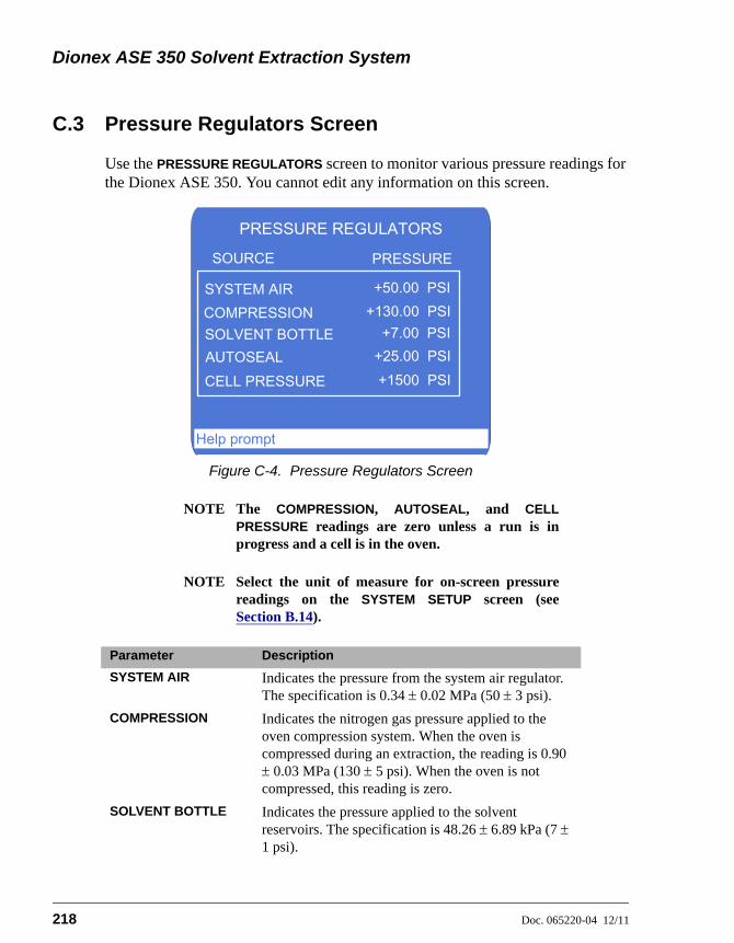
Dionex ASE 350 Solvent Extraction System
218 Doc. 065220-04 12/11
C.3 Pressure Regulators Screen
Use the PRESSURE REGULATORS screen to monitor various pressure readings for the Dionex ASE 350. You cannot edit any information on this screen.
NOTE The COMPRESSION, AUTOSEAL, and CELLPRESSURE readings are zero unless a run is inprogress and a cell is in the oven.
NOTE Select the unit of measure for on-screen pressurereadings on the SYSTEM SETUP screen (seeSection B.14).
Figure C-4. Pressure Regulators Screen
Parameter Description
SYSTEM AIR Indicates the pressure from the system air regulator. The specification is 0.34 0.02 MPa (50 3 psi).
COMPRESSION Indicates the nitrogen gas pressure applied to the oven compression system. When the oven is compressed during an extraction, the reading is 0.90 0.03 MPa (130 5 psi). When the oven is not compressed, this reading is zero.
SOLVENT BOTTLE Indicates the pressure applied to the solvent reservoirs. The specification is 48.26 6.89 kPa (7 1 psi).
PRESSURE REGULATORS
SYSTEM AIR
PRESSURESOURCE
+50.00 PSI+130.00 PSI
+7.00 PSI+25.00 PSI+1500 PSI
COMPRESSIONSOLVENT BOTTLEAUTOSEALCELL PRESSURE
Help prompt
C • Diagnostic Screens
Doc. 065220-04 12/11 219
AUTOSEAL Indicates the pressure applied to the AutoSeal air cylinder. When the air cylinder is actuated, the reading is 172.37 14 kPa (25 2 psi). When the air cylinder is not actuated, this reading is zero.
CELL PRESSURE Indicates the pressure applied to the cell.

Dionex ASE 350 Solvent Extraction System
220 Doc. 065220-04 12/11
C.4 Usage Log Screen
Use the USAGE LOG screen to check the number of extractions the system has run, the number of cycles the static valve has performed, and other performance history. This information can be helpful in scheduling the routine replacement of certain parts.
Not all of the reported information can be displayed on the screen at once; use the arrow up and down buttons to scroll through the list.
NOTE You can also view performance history on the Wellnesspanel in Chromeleon (see Section 2.5.3). To reset theusage counters on the Wellness panel, contact ThermoFisher Scientific.
Figure C-5. Usage Log Screen
Parameter Description
TOTAL PUMP STROKES
Indicates the number of pump strokes performed since the Dionex ASE 350 was installed or the pump strokes counter was last reset (read-only).
PUMP SEAL STROKES
Indicates the number of pump strokes performed since the Dionex ASE 350 was installed or the pump piston seals were last replaced. To reset the pump seal counter, press the button with the decimal point on the numeric keypad.
USAGE LOG
LCD HOURS USESTATIC TOTAL CYCLE
TOTAL PUMP STROKES 13013024
41
PUMP SEAL STROKESMODULE HOURS USE
Help prompt
C • Diagnostic Screens
Doc. 065220-04 12/11 221
MODULE HOURS USE
Indicates the number of hours the Dionex ASE 350 has been in operation (read-only).
LCD HOURS USE Indicates the number of hours the front panel display has been lighted (read-only).
STATIC TOTAL CYCLE
Indicates the number of cycles the static valve has performed (read-only).
STATIC SEAL CYCLES
Indicates the number of cycles the static valve seal has performed since the Dionex ASE 350 was installed or the static seals were last replaced. To reset the static seal counter, press the button with the decimal point on the numeric keypad.
EXTRACTION COUNT
Indicates the number of runs performed since the Dionex ASE 350 was installed (read-only).

Dionex ASE 350 Solvent Extraction System
222 Doc. 065220-04 12/11
C.5 Error Log Screen
Use the ERROR LOG screen to review errors that occurred during operation.
When an error occurs during a run, the Dionex ASE 350 displays an error message and records the error (including the cell and the collection vessel affected) in an error log. Unless the error causes a shutdown, the Dionex ASE 350 continues the run. Any additional errors that occur during a series of runs will also be recorded in the error log. A maximum of 20 errors can be logged.
To view the list of errors, display the ERROR LOG screen (press Menu, 6, and then 5). If there are too many errors to be shown on one screen, use the arrow up and down buttons to scroll through the list.
Errors remain on the screen until deleted; to delete them, press the button with the decimal point on the numeric keypad.
See Section 4.1 for explanations of all error messages, as well as troubleshooting guidance.
Figure C-6. Error Log Screen
ERROR #
ERROR LOG
21 AutoSeal to tray, C# V# ----
ERROR MESSAGE
Help promptHelp prompt
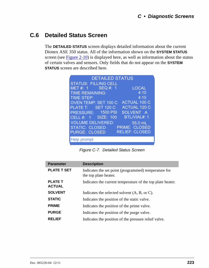
C • Diagnostic Screens
Doc. 065220-04 12/11 223
C.6 Detailed Status Screen
The DETAILED STATUS screen displays detailed information about the current Dionex ASE 350 status. All of the information shown on the SYSTEM STATUS screen (see Figure 2-10) is displayed here, as well as information about the status of certain valves and sensors. Only fields that do not appear on the SYSTEM
STATUS screen are described here.
Figure C-7. Detailed Status Screen
Parameter Description
PLATE T SET Indicates the set point (programmed) temperature for the top plate heater.
PLATE T ACTUAL
Indicates the current temperature of the top plate heater.
SOLVENT Indicates the selected solvent (A, B, or C).
STATIC Indicates the position of the static valve.
PRIME Indicates the position of the prime valve.
PURGE Indicates the position of the purge valve.
RELIEF Indicates the position of the pressure relief valve.
Help prompt
DETAILED STATUS
TIME REMAINING:
CELL #: 1 BTL/VIAL#: 1
TIME STEP:
STATIC: CLOSED PRIME: CLOSEDRELIEF: CLOSEDPURGE: CLOSED
SIZE: 100
4:10
55.0 mL
STATUS: FILLING CELLLOCAL
OVEN TEMP: SET 100 C ACTUAL 100 C
MET #: 1 SEQ #: 1
PLATE T:
VOLUME DELIVERED:
PRESSURE:
4:10
ACTUAL 120 CSOLVENT A
SET 120 C1500 PSI

Dionex ASE 350 Solvent Extraction System
224 Doc. 065220-04 12/11
C.7 Hydrocarbon Status Screen
Use the HYDROCARBON STATUS screen to monitor the current hydrocarbon level at the Dionex ASE 350 installation site and to adjust the solvent vapor threshold, if necessary.
Figure C-8. Hydrocarbon Status Screen
Parameter Description
CONCENTRATION Indicates the hydrocarbon level detected by the hydrocarbon sensor (read-only).
THRESHOLD Selects the solvent vapor threshold (1 to 500). If the threshold is often tripped, increase the selected value; if the threshold is never tripped, decrease the selected value.
HYDROCARBON STATUS
CONCENTRATION: 0.0023100THRESHOLD:
Help prompt

Doc. 065220-04 12/11 225
D • Reordering Information
Part Number Item Quantity
Sample Cells and Accessories
068095 Stainless steel sample cells, 1 mL (assembled) Pkg. 6
068096 Stainless steel sample cells, 5 mL (assembled) Pkg. 6
068097 Stainless steel sample cells, 10 mL (assembled) Pkg. 6
068098 Stainless steel sample cells, 22 mL (assembled) Pkg. 6
068099 Stainless steel sample cells, 34 mL (assembled) Pkg. 6
068100 Stainless steel sample cells, 66 mL (assembled) Pkg. 6
068101 Stainless steel sample cells, 100 mL (assembled) Pkg. 6
068085 Stainless steel sample cell, 1 mL (assembled) 1
068086 Stainless steel sample cell, 5 mL (assembled) 1
068087 Stainless steel sample cell, 10 mL (assembled) 1
068088 Stainless steel sample cell, 22 mL (assembled) 1
068089 Stainless steel sample cell, 34 mL (assembled) 1
068090 Stainless steel sample cell, 66 mL (assembled) 1
068091 Stainless steel sample cell, 100 mL (assembled) 1
068261 Stainless steel sample cell body, 1 mL 1
068262 Stainless steel sample cell body, 5 mL 1
068263 Stainless steel sample cell body, 10 mL 1
068264 Stainless steel sample cell body, 22 mL 1
056646 Stainless steel sample cell body, 34 mL 1
056696 Stainless steel sample cell body, 66 mL 1
056693 Stainless steel sample cell body, 100 mL 1
056775 Stainless steel frits for sample cell end caps Pkg. 50
068106 Stainless steel end caps for sample cells (includes frits and seals)
Pkg. 2
068104 Zirconium sample cells, 66 mL (assembled) Pkg. 3
068105 Zirconium sample cells, 100 mL (assembled) Pkg. 3
068102 Zirconium sample cell, 66 mL (assembled) 1
068103 Zirconium sample cell, 100 mL (assembled) 1
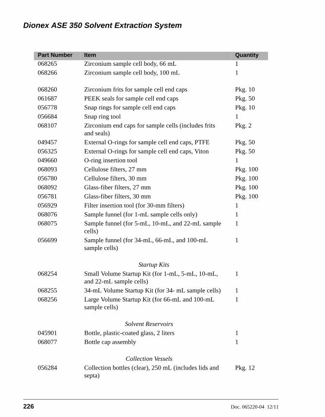
Dionex ASE 350 Solvent Extraction System
226 Doc. 065220-04 12/11
068265 Zirconium sample cell body, 66 mL 1
068266 Zirconium sample cell body, 100 mL 1
068260 Zirconium frits for sample cell end caps Pkg. 10
061687 PEEK seals for sample cell end caps Pkg. 50
056778 Snap rings for sample cell end caps Pkg. 10
056684 Snap ring tool 1
068107 Zirconium end caps for sample cells (includes frits and seals)
Pkg. 2
049457 External O-rings for sample cell end caps, PTFE Pkg. 50
056325 External O-rings for sample cell end caps, Viton Pkg. 50
049660 O-ring insertion tool 1
068093 Cellulose filters, 27 mm Pkg. 100
056780 Cellulose filters, 30 mm Pkg. 100
068092 Glass-fiber filters, 27 mm Pkg. 100
056781 Glass-fiber filters, 30 mm Pkg. 100
056929 Filter insertion tool (for 30-mm filters) 1
068076 Sample funnel (for 1-mL sample cells only) 1
068075 Sample funnel (for 5-mL, 10-mL, and 22-mL sample cells)
1
056699 Sample funnel (for 34-mL, 66-mL, and 100-mL sample cells)
1
Startup Kits
068254 Small Volume Startup Kit (for 1-mL, 5-mL, 10-mL, and 22-mL sample cells)
1
068255 34-mL Volume Startup Kit (for 34- mL sample cells) 1
068256 Large Volume Startup Kit (for 66-mL and 100-mL sample cells)
1
Solvent Reservoirs
045901 Bottle, plastic-coated glass, 2 liters 1
068077 Bottle cap assembly 1
Collection Vessels
056284 Collection bottles (clear), 250 mL (includes lids and septa)
Pkg. 12
Part Number Item Quantity
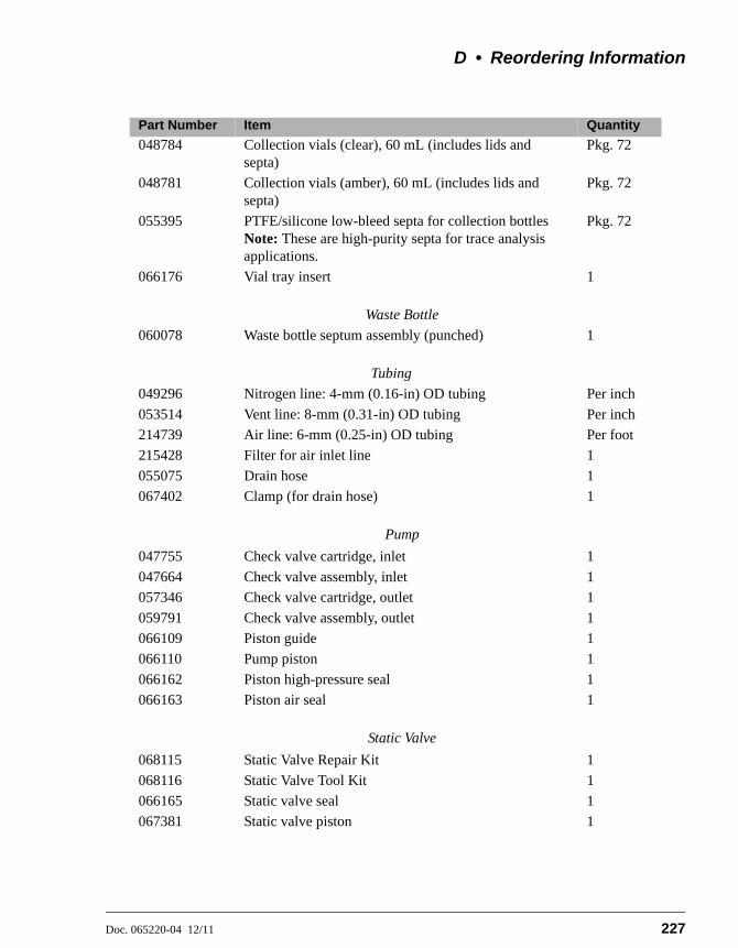
D • Reordering Information
Doc. 065220-04 12/11 227
048784 Collection vials (clear), 60 mL (includes lids and septa)
Pkg. 72
048781 Collection vials (amber), 60 mL (includes lids and septa)
Pkg. 72
055395 PTFE/silicone low-bleed septa for collection bottlesNote: These are high-purity septa for trace analysis applications.
Pkg. 72
066176 Vial tray insert 1
Waste Bottle
060078 Waste bottle septum assembly (punched) 1
Tubing
049296 Nitrogen line: 4-mm (0.16-in) OD tubing Per inch
053514 Vent line: 8-mm (0.31-in) OD tubing Per inch
214739 Air line: 6-mm (0.25-in) OD tubing Per foot
215428 Filter for air inlet line 1
055075 Drain hose 1
067402 Clamp (for drain hose) 1
Pump
047755 Check valve cartridge, inlet 1
047664 Check valve assembly, inlet 1
057346 Check valve cartridge, outlet 1
059791 Check valve assembly, outlet 1
066109 Piston guide 1
066110 Pump piston 1
066162 Piston high-pressure seal 1
066163 Piston air seal 1
Static Valve
068115 Static Valve Repair Kit 1
068116 Static Valve Tool Kit 1
066165 Static valve seal 1
067381 Static valve piston 1
Part Number Item Quantity

Dionex ASE 350 Solvent Extraction System
228 Doc. 065220-04 12/11
Miscellaneous
062819 Pelletized diatomaceous earth (DE) 1 kg
080024 ASE Prep CR Resin 500 g
954746 Fast-blow IEC127 fuse, 10 amps 1
960777 USB cable, 6 ft 1
046985 Flathead screwdriver 1
068955 Source needle assembly 1
068247 Heat exchanger 1
938914 Hydrocarbon sensor 1
Part Number Item Quantity

Doc. 065220-04 12/11 229
E • Theory of ASE
E.1 Introduction
Scientists are continually striving to develop a means to accomplish desired results faster, better, cheaper, and more efficiently. However, the application of new technologies to sample preparation has often lagged behind advances in the determinative steps of the overall analytical scheme. Consider the major technological changes in chromatography that have occurred in the last few years. What a contrast exists between the first commercial gas chromatographs (GC) introduced in the late 1950s and the modern GCs we have today! On the other hand, analytical chemists can still be seen preparing samples for chromatographic analysis using the same type of Soxhlet apparatus that was used to prepare samples for the first GC instruments. In fact, Soxhlet apparatus has been in use, with few modifications, for over 100 years. Traditional extraction techniques suffer from several shortcomings. They often take long periods of time (several hours), use large quantities of solvent (hundreds of milliliters per sample), and require a great deal of labor and user intervention.
In addition to the costs associated with sample preparation, studies have shown that sample preparation is the primary source of errors in any analytical process. If we want to have the biggest impact on improving the performance of any analytical method, we would be well-advised to attack the sample preparation portion of the method. That is one reason that Thermo Fisher Scientific has been involved in research dealing with sample preparation for many years. Accelerated solvent extraction (ASE) was developed to address the problems inherent with traditional extraction techniques such as Soxhlet and sonication.
ASE is an automated extraction technique that uses elevated temperatures and pressures to achieve extractions in very short periods of time (for example, 10 g of sample can be extracted in less than 15 minutes, using less than 15 mL of solvent). Why would we do extractions at elevated temperatures and pressures? There are several physicochemical reasons for this. First, let's consider temperature.
It is a well-known fact that the use of higher temperatures increases the capacity of solvents to solubilize analytes. For example, the solubility of anthracene increases nearly 13-fold as we increase temperature from 50 to 150 °C. Increasing the temperature also leads to faster diffusion rates. This means that analytes move more quickly from the boundary layer near the surface of the matrix from which

Dionex ASE 350 Solvent Extraction System
230 Doc. 065220-04 12/11
they are extracted to the bulk solvent at higher temperatures. Higher temperatures also mean lower solvent viscosities, meaning that the solvent can penetrate the pores of the matrix more easily. Finally, increased temperature makes it easier to disrupt solute-matrix interactions (dipole attractions, van der Waals forces, hydrogen bonding, etc.) and remove analytes from the matrix. Taken all together, the net effect is that doing extractions at elevated temperatures means that the extractions happen much faster and use less solvent. However, temperature alone is not enough because many of the organic solvents used in extractions boil at relatively low temperatures. This is one limitation of techniques such as Soxhlet or automated Soxhlet; the highest temperature at which extractions take place in these techniques is the boiling point of the solvent.
If sufficient pressure is exerted on the solvent during the extractions, temperatures above the boiling point can be used. This means that all of the advantages of working at elevated temperature can be realized even with solvents with relatively low boiling points. Operating at elevated pressures also helps the overall extraction process to happen more quickly. Pumping solvent through a packed bed is easier at elevated pressures. Pressurized solvent is forced into the pores of the sample matrix, coming into more intimate contact with analytes in those areas. Hence, the combination of elevated temperatures and pressures allows extractions to occur rapidly and completely. For a more detailed discussion of the theoretical consideration of ASE, consult Richter et al., Anal. Chem. 1996, 68, 1033-1039.
E.2 Operation
ASE was first described in 1995 and 1996 (1–9). As a technique, it has grown steadily in use since that time. Figure E-1 shows a schematic of the ASE process.
To perform an extraction, the solid sample is loaded into a sample cell (1 to 100 mL) and the end caps (each containing a frit) are tightened by hand onto the cells. The filled sample cells are loaded onto a cell tray and collection vessels (bottles or vials) are loaded onto a collection tray. A robotic arm transfers each cell separately into the oven for extraction. The oven is maintained at the selected operating temperature throughout the extractions (room temperature to 200 °C). The cell design and associated fluid apparatus allow operation of the extractions at elevated pressures (500 to 1500 psi) to maintain the solvents as liquids at temperatures above their boiling points. The temperature and pressure are controlled independently for each cell regardless of the solvent used, the moisture or mineral content of the sample, or any characteristic of the matrix that might affect the actual extraction temperature. This is an advantage when compared to

E • Theory of ASE
Doc. 065220-04 12/11 231
microwave extraction, in which the actual pressure and temperature of the extraction are influenced strongly by the above mentioned sample parameters.
Figure E-1. Schematic of the ASE Process
MixingValve
ReliefValve
In-cell Cleanup
Pretreated Matrix
Oven
Solvent
Solvent Extraction
Collection Bottle
Pump
Solvent Solvent
Chemistry
Static Valve

Dionex ASE 350 Solvent Extraction System
232 Doc. 065220-04 12/11
Once the cell is in place in the oven, the pump immediately begins to deliver the solvent of choice to the sample cell. Single solvents or premixed solvents can be used from a single collection vessel, or any combination of up to three different solvents can be programmed. Once solvent has made its way through the sample cell and reaches the collection vessel, the static valve closes to allow pressurization of the cell. Since the solvent expands as it heats, the pressure in the cell will increase when the static valve closes. When the pressure reaches 200 psi above the set point, the static valve rapidly opens to relieve the pressure and then closes again. The pump also delivers fresh solvent to the cell in an effort to return the pressure to the set point value. This addition of fresh solvent during ASE is analogous to fresh solvent dripping down from the condenser onto the extraction thimble during Soxhlet extraction.
During the first phase of a run, called the heat-up time, the cell contents are heated by the oven to the selected operating temperature. Heat-up times vary between 5 minutes for 100 °C and 9 minutes for 200 °C. After the heat-up time, the extraction enters a static period with a duration selected by the user. Typical static times are 5 minutes, but can vary from 0 to 2000 minutes. After the static time, fresh solvent is pumped through the cell to remove extracted analytes while the sample and solvent are still hot. The amount used for the rinse can vary from 0% to 150% of the volume of the cell used for the extraction (40% to 60% is most common).
The user can select the number of times the sample will be in the static mode, and enter this as the number of static cycles. The rinse volume is divided by the number of static cycles, so that fresh solvent is present at the beginning of each static cycle. In other words, if one static cycle is selected, the entire rinse volume will be pumped through the cell at the end of the static time. If three static cycles are selected, one-third of the total rinse volume will be pumped through the cell at the end of each static cycle. From one to nine static cycles can be programmed; one cycle is the most common.
Following the final solvent rinse, solvent is purged out of the cell (using nitrogen at 150 psi) for a predetermined period of time. The total time for the extraction is usually less than 15 minutes and the amount of solvent used is approximately 1.5 times the volume of the sample cell (for example, about 15 mL for a 10-mL cell).
The extracts are delivered to the collection vessels through a filter, and in many cases do not need any additional preparation prior to analysis. Since the extract is diluted by the total volume of extraction solvent plus the rinse solvent, a further concentration step (evaporation, solid-phase extraction, etc.) may be required when performing trace analysis.

E • Theory of ASE
Doc. 065220-04 12/11 233
Upon completion of the purge step, the cell is returned to the tray and the next sample is taken to the oven to begin the extraction process again. Current ASE instrumentation allows for unattended overnight operation of the extraction system without user intervention.
Under method control, each sample is extracted using the same conditions. When using sequence control, each cell can be extracted using different conditions, including different solvents (if multiple solvent reservoirs are installed).
ASE instrumentation includes many features designed to minimize safety issues with the use of solvents at elevated temperatures and pressures. Among the safety measures in place are: flammable vapor sensors, liquid leak detectors, checks for collection vessel overfill conditions, three levels of overpressurization prevention (electronic and mechanical), solvent flow monitoring, and pneumatic source pressure monitoring.
E.3 Method Optimization
Method optimization consists of two main elements: sample preparation and extraction parameters.
E.3.1 Sample Preparation
Sample preparation is an essential part of every solvent-based extraction procedure. While many sample types can be efficiently extracted without any pretreatment, other samples require some manipulation for an efficient extraction to occur. In general, the same sample preparation that is done prior to Soxhlet or sonication extraction should be done prior to extraction by ASE. This section discusses three sample preparation techniques: grinding, dispersing, and drying.
Grinding
For an efficient extraction to occur, the solvent must make contact with the target analytes. The more surface area that can be exposed in a sample, the faster an extraction will occur. Samples with large particle sizes should be ground prior to extraction. Efficient extraction requires a minimum particle size, generally smaller than 1 mm. Grinding can be accomplished with a conventional mortar and pestle or with electric grinders and mills. Often a large, representative sample can be ground and weighed portions of the ground sample can be used for extraction. Soil

Dionex ASE 350 Solvent Extraction System
234 Doc. 065220-04 12/11
and sediment samples generally do not need to be ground, although it may be necessary to remove stones or sticks from the samples prior to extraction. Polymer samples must be in a ground state for an efficient extraction of additive compounds. Materials such as polymers and rubbers are best ground at reduced temperatures (for example, while chilling with liquid nitrogen). Animal or plant tissue samples can be homogenized using any procedure, including a blender or tissue homogenizer.
The effects of sample surface area on extraction efficiency have been studied. Three samples of mozzarella cheese were prepared differently and extracted for fat content using ASE. The chopped samples were cut into pieces ranging in size between 2 and 5 mm. The ground samples were ground with diatomaceous earth (1:2). Each sample was extracted with a mixture of hexane:2-propanol (3:2) using these ASE conditions: 1000 psi, 125 °C, 6-minute heat-up, three 10-minute static cycles, 100% rinse, 60-second purge, and one 11-mL cell containing one cellulose filter. The extracts were analyzed gravimetrically. The ASE results were compared to results obtained from Mojonnier extraction (see Figure E-2). These results demonstrate that increasing the surface area by grinding the sample results in higher extraction efficiencies.
Figure E-2. Effect of Sample Particle Size for ASE vs. Mojonnier Extraction. Whole cheese (0.5 to 1.5 cm size); chopped (2 to 5 mm); ground (mixed thoroughly with
diatomaceous earth)
0
10
20
30
40
50
60
70
80
90
100
Whole Chopped Ground
Per
cen
tR
eco
very
vsM
ojo
nn
ier
E • Theory of ASE
Doc. 065220-04 12/11 235
Dispersing
The aggregation of sample particles may prevent efficient extraction. In these cases, dispersing the sample with an inert material such as sand or diatomaceous earth will assist in the extraction process. Dispersing is also recommended with samples that tend to compact in the sample cell outlet. These samples normally contain very small particles that can adhere tightly to each other when under pressure. Some samples may compact in the sample cell due to the high pressures used in ASE. Mixing the sample with sand or diatomaceous earth will prevent this compacting of the sample that can lead to occlusion of the sample cell.
When extracting soil or sediment samples, it is important to mix the samples with a dispersing agent unless the samples are completely dry. If the soil or sediment samples are wet or high in clay, the samples can be mixed with either sand or diatomaceous earth, but the latter is preferred because it will adsorb some of the water and make the sample easier to handle.
It is important to periodically run blank extractions of the dispersing agent to verify its cleanliness.
Drying
Samples do not have to be completely dry to achieve efficient extractions with ASE. This depends on the analytes and the solvent used for extraction. High levels of water can prevent nonpolar organic solvents from reaching the target analytes. The use of more polar solvents (for example, acetone and methanol) or solvent mixtures (for example, hexane/acetone and methylene chloride/acetone) can assist in the extraction of wet samples. Elevated temperatures can also improve the extraction efficiency of wet samples (10). In addition, the solvent being used will impact the type of drying that needs to be done to a sample and whether it need to be done at all. With nonpolar solvents, the need for drying is more important. One can also use a bridge solvent such as acetone (for example, hexane/acetone, 1:1) mixed with a nonpolar solvent to improve the extraction efficiency of wet samples.
Sample drying prior to extraction is an efficient way to handle wet samples. Drying can be accomplished by direct addition of a drying agent such as diatomaceous earth. The use of magnesium sulfate is not recommended with ASE due to the extremely hard, concrete-like material
Dionex ASE 350 Solvent Extraction System
236 Doc. 065220-04 12/11
that can be produced. Sodium sulfate should be used only with nonpolar solvents (hexane, heptane, toluene, etc.). Sodium sulfate can become soluble in the extraction process and then be deposited in the exit lines. Oven drying and freeze drying are other viable alternatives for sample drying prior to extraction; however, these procedures may compromise the recovery of volatile compounds.
The sample drying or dispersing agent should be mixed thoroughly with the sample in a small vial, beaker, or mortar, and then added to the sample cell. For quantitative transfer, the mixing vessel can be rinsed with 1 to 2 mL of the extraction solvent using a Pasteur pipette, and this volume added directly to the sample cell. The main purpose of mixing with a drying agent like diatomaceous earth is not to remove all water from the sample but to make it easy to transfer the sample into the sample cell. If elevated temperatures are used, then some water will be removed from the sample during the extraction process. In this case, sodium sulfate can be added to the extract after collection to remove water.
E.3.2 Extraction Parameters
Solvent
For an efficient extraction, the solvent must be able to solubilize the target analytes while leaving the sample matrix intact. The polarity of the extraction solvent should closely match that of the target compounds. The common adage of “like dissolves like” is very applicable in ASE. Mixing solvents of differing polarities can be used to extract a broad range of compound classes. Generally, if a particular solvent has been shown to work well in a conventional procedure, it will also work well in ASE. Compatibility with the post-extraction analytical technique, the need for extract concentration (solvent volatility), and the cost of the solvent should all be considered. While many ASE methods recommend solvents or solvent mixtures for specific analyte classes, there may be alternatives that better fit the needs of a particular laboratory. For example, Schantz (11) showed that dichloromethane/acetone or acetonitrile can be used to get complete extraction of polycyclic aromatic compounds. If GC or GC-MS is the analytical method, then dichloromethane/acetone would be the solvent of choice. If HPLC is the determinative step, then acetonitrile would be the solvent of choice. Solvent choice will also determine the
E • Theory of ASE
Doc. 065220-04 12/11 237
level of coextractables along with the analytes. Generally, the more polar the solvent or solvent mixture, the less selective it will be.
Solvents that exhibit marginal results at ambient conditions may perform adequately under ASE conditions. Most liquid solvents, including water and buffered aqueous mixtures, can be used in ASE. Strong acids (HCl, HNO3, H2SO4) are not recommended for use with stainless steel cells because they may damage the cells. However, small amounts of these acids can be used with zirconium cells. When required, weak acids such as acetic or phosphoric can be used. These should be added to aqueous or polar solvents in the 1-10% (v/v) range.
For extraction of polymer samples, select a solvent that will extract the additives but not the matrix itself. For example, isopropanol with small levels of cyclohexane has been shown to work well for the extraction of phenolic antioxidant additives in polymers.
Temperature
Temperature is the most important parameter used in ASE extraction. As the temperature is increased, the viscosity of the solvent is reduced, thereby increasing its ability to wet the matrix and solubilize the target analytes. The added thermal energy also assists in breaking analyte-matrix bonds and encourages analyte diffusion from the matrix surface.
When developing a new method, start at 100 °C or, if the target analytes have a known thermal degradation point, start at 20 °C below this level. Most ASE applications operate in the 75 to 125 °C range, with 100 °C the most common temperature for environmental applications. If the sample has a tendency to melt in the sample cell, a cellulose thimble can be used to facilitate extraction and sample removal.
Table E-1 shows an example of the effect of temperature for the extraction of petroleum hydrocarbons (TPH) from soil. Note that not only does the analyte recovery increase, but the reproducibility improves as a function of temperature.

Dionex ASE 350 Solvent Extraction System
238 Doc. 065220-04 12/11
There appears to be confusion about the purpose of the preheat function available on ASE systems. When the preheat function is used, a cell is placed in the oven and heated without any solvent being pumped into the cell. This function was originally developed to allow pre-extraction derivatization of analytes or the drying of samples by blowing nitrogen through the cell while it is heated. The preheat function should not be used in normal operation of ASE. In general, this should be set to zero minutes. If used, recoveries of more volatile compounds (for example, organochlorine pesticides) will be greatly reduced.
Pressure
The effect of pressure is to maintain the solvents as liquids while above their atmospheric boiling points, and to rapidly move the fluids through the system. The pressures used in ASE are well above the thresholds required to maintain the solvents in their liquid states, so pressure adjustments for changing solvents are not required. Changing the pressure will have very little impact on analyte recovery, and it is not considered a critical experimental parameter. Dionex ASE 350 extractions are performed at 1500 psi.
Static Cycles
The use of static cycles was developed to introduce fresh solvent during the extraction process, which helps to maintain a favorable extraction equilibrium. This effectively approximates dynamic extraction conditions without the need for troublesome flow restrictors to maintain pressure. When more than one cycle is used in a method, the rinse volume is divided by that number. When the first static time is complete, the divided portion of the rinse volume is delivered to the cell, with the “used”
Temperature Recovery RSD (%)
27 °C 81.2 6.0
50 °C 93.2 5.0
75 °C 99.2 2.0
100 °C 102.7 1.0
Samples were analyzed by IR, with n = 5.
Table E-1. Effect of Temperature on TPH; Extraction from Soil
E • Theory of ASE
Doc. 065220-04 12/11 239
solvent directed to the collection vessel. The system then holds the sample and solvent for a second static period. The nitrogen purge step is initiated only after the final static cycle. Because the original rinse volume has only been divided, no additional solvent is used for the extraction.
Static cycles have proven to be useful for sample types with a very high concentration of analyte, as well as samples with difficult to penetrate matrices. The static time can be adjusted to minimize the total extraction time. For example, three 3-minute static cycles can be used in place of one 10-minute static step. When low temperature extractions are desired (< 75 °C), multiple static cycles should be used to compensate for the smaller amount of solvent introduced during the heat-up step, as the static valve pulses to regulate the pressure.
Time
Certain sample matrices can retain analytes within pores or other structures. Increasing the static time at elevated temperatures can allow these compounds to diffuse into the extraction solvent. The effect of static time should always be explored in conjunction with static cycles, in order to produce a complete extraction in the most efficient way possible. Generally, ASE extractions are completed in less than 20 minutes; if times longer than this are necessary to get complete extraction, then a higher temperature, different solvent, or multiple static cycles should be explored to reduce the overall extraction time.
E.4 Method Development
A representative sample should be prepared as outlined in the discussion on sample preparation (see Section E.3.1). Select a sample cell size that most closely matches the sample size. The sample cells do not need to be filled completely; however, a full cell will use less solvent in the extraction process than a partially filled one. A recommended set of conditions to begin method development are as follows: 1500 psi, 100 °C (or 20 °C below analyte decomposition temperature), 5-minute static time, 40% rinse volume, 60-second purge (up to 300 seconds for a 100-mL cell), and one static cycle. If desired, a sequence can be set up to extract each of a series of samples under a different set of conditions and collect them in separate collection vessels. Samples can also be extracted multiple times to

Dionex ASE 350 Solvent Extraction System
240 Doc. 065220-04 12/11
determine extraction completeness. If analyte is present in the second or third vessel, then the initial conditions need to be changed.
The order of change would be (1) change the solvent, (2) increase the temperature, (3) add a second or third cycle, and (4) increase the time. In this way, one can quickly determine the optimized extraction conditions for a particular analyte and matrix.
E.5 Selectivity in ASE
Selectivity in extraction is defined here as being able to extract compounds of interest with little or no interfering coextracted compounds. ASE is generally considered to be an exhaustive extraction technique, and often the extracts obtained from complex samples contain compounds that can interfere with the determination of the desired analytes. Selectivity in ASE could come from the manipulation of the extraction conditions to minimize coextractables while maximizing analyte recovery. There are three basic procedures to obtain selective extraction in ASE or, in other words, to generate extracts that contain the compounds of interest and few, if any, interfering compounds. The three techniques are choice of temperature, choice of solvent, and use of adsorbents in the sample cell. Of course, the most powerful method is to use variations of all three to fine-tune the selectivity during the ASE process.
The choice of temperature alone can affect selectivity. The higher the temperature for the extraction, the less selective the results. Lowering the temperature will make ASE more selective, but the recovery of analytes can diminish unless the time is increased. Similarly, selectivity is decreased when using more polar solvents. However, one can use a series of solvents of increasing polarity to obtain selective extractions or “fractionation.”
Dark-colored fruits such as blueberries are being studied for their antioxidant content. These compounds are polyphenolic in nature and require polar solvents for extraction. However, if the fruit sample is extracted with a polar solvent like methanol, acetonitrile, ethanol, or water, the resulting extract contains many compounds that make the analysis for antioxidant compounds more challenging. We have found that the samples can first be extracted with nonpolar solvents like hexane or DCM to remove unwanted wax compounds. Then, by extracting the same sample with solvents of increasing polarity and collecting the fractions in separate vessels, one can obtain extracts that are easier to analyze.

E • Theory of ASE
Doc. 065220-04 12/11 241
Figure E-3 is a photo of extracts obtained from a single sample of wild blueberries extracted with hexane, followed by DCM, ethyl acetate, acetonitrile, and then ethanol. Clearly, using a fractionation procedure like this can offer advantages when analyzing extracts of plant materials that can contain several hundred compounds of interest.
Another unique use of solvent selectivity was reported by Draisci et al. (12). The authors reported the use of ASE for the extraction of corticosteroids from beef liver prior to analytical determination by LC-MS. First, the sample was extracted with hexane to remove the majority of lipids that would interfere in the determinative step. Next, the samples were extracted with hexane/ethyl acetate to remove the steroid compounds. Solvent fractionation using ASE is an area that needs to be explored to more fully understand its potential.
The use of sorbents in the sample cell along with the sample has offered some of the highest level of selectivity in ASE. Typically, the adsorbent is loaded into the sample cell first (outlet end) and the sample is loaded on top of the adsorbent. This way, the flow of solvent during the extraction is such that unwanted compounds are retained in the cell by the adsorbent. Azalea et al. (13) first reported the use of alumina in sample cells to retain lipids when extracting PCBs from fish tissue
Figure E-3. Selectivity in ASE. The same sample of blueberries was extracted with (from left to right) hexane, DCM, ethyl acetate, acetonitrile, and ethanol
Dionex ASE 350 Solvent Extraction System
242 Doc. 065220-04 12/11
using ASE. They reported that, as the temperature of the extraction goes up or as the polarity of the solvent increases, the capacity of the alumina to retain lipids decreases. For example, if hexane or heptane is the extraction solvent, heat-activated alumina will retain about 70 mg of lipid per gram of alumina. If DCM is used, then the capacity is only about 35 mg lipid/g of alumina. If the correct amount of sorbent is used, then extracts can be produced using ASE that require no additional post-extraction treatment other than volume adjustment.
The most common use of adsorbents in ASE has been for the extraction and determination of nonpolar compounds such as PCBs, OCPs, PCDDs, and PCDFs in high lipid content matrices such as food or animal tissue. Other adsorbents that have been used include copper, C18 resin, Florisil, silica gel, acid-impregnated silica gel, and ion-exchange resins. Table E-2 shows a summary, with related references.
There are a few interesting things to note from this table. Acid-impregnated silica gel has the highest capacity for lipid retention of all the adsorbents that were reported: It has roughly double the capacity of alumina. The sulfuric acid is typically present on the silica at 40% (wt/wt). Copper powder (cleaned with HCl first) can be used to retain sulfur when extracting sediment samples.
Gentili and colleagues (21) reported an interesting use of a C18 adsorbent. In this case, they were extracting polar antibiotics (sulfonamides) from animal tissues. They put C18 material in the outlet of the cell to retain some of the lipids that extracted with the analytes. Then, the samples were placed in a freezer to allow
Adsorbent Uses References
Silica Removes nonpolar lipids 4
Florisil Removes nonpolar lipids 15, 16
Alumina Removes nonpolar lipids and colored compounds
13, 17, 18
C18 resin Removes nonpolar lipids 19, 20
Ion-exchange resins Removes ionic interferences
22
Copper powder Removes sulfur 11, 23
Carbon Assists with purification of PCDDs, PCDFs, and coplanar PCBs
24, 25
Table E-2. List of Adsorbents Used in ASE
E • Theory of ASE
Doc. 065220-04 12/11 243
them to separate and harden. The samples were centrifuged and aliquots were removed and analyzed. This is a case in which the analytes were polar, the solvent was polar (water), and the matrices (baby food and meat) were polar. This is in contrast to several publications in which the analytes were relatively nonpolar (PCBs, PCDDs, OCPs, etc.) and the solvents were nonpolar (like hexane). In this case, the adsorbents have higher capacity than when the extraction solvent is polar.
Ion-exchange resins can be used to remove unwanted ionic species (22). For example, Thermo Fisher Scientific has been involved in projects to determine perchlorate in soils and vegetation samples. Water at 80 °C was used as the extraction solvent. Alumina was used to remove colored compounds such as chlorophyll. Ion-exchange resins were placed in the ASE cells to remove chloride and sulfate. This allowed the determination of perchlorate at the sub-ppb levels.
Björklund and his coworkers have published many articles on the use of adsorbents in-line in ASE cells to improve selectivity (25–31), especially for PCB and PCDD analysis. One article discusses the results of the development of a scheme that allows the separation of non-ortho PCBs and PCDD/Fs from the bulk of the PCBs, gravimetric fat determinations, and minimum post-extraction clean-up prior to analysis (25). This offers an obvious savings in time, labor, and solvent costs over traditional extraction procedures followed by clean-up methods such as GPC.
ASE has been shown to work well for the extraction of acrylamide from many food matrices (32). The use of adsorbents in the ASE cell has now been extended to this application (33). Florisil was added to the cell when extracting coffee or chocolate samples. The authors report that 6 g of Florisil in the cell, along with 2 g of sample, produced clear extracts without any interferences. Figure E-4 shows the effect of varying the level of the Florisil.

Dionex ASE 350 Solvent Extraction System
244 Doc. 065220-04 12/11
One of the most fascinating uses of selective extraction with ASE was reported by Poerschmann et al. (34, 35). In this work, a combination of adsorbents in the cells, varying temperature, and solvent allowed fractionation to be achieved that was superior to conventional SPE after exhaustive extraction. This work demonstrated the fractionation of lipid classes using sequential extractions.
Unmodified silica and cyanopropyl silica were used as the adsorbents in the outlet of the cells. The biological samples were extracted with hexane/acetone (9:1, v/v) at 50°C to remove the neutral lipids. Then, the same samples were extracted with chloroform/methanol (1:4, v/v) at 110 °C to remove polar lipids such as phospholipids and hydroxy-containing fatty acids.
What is intriguing about this work is that the authors demonstrated that this fractionation scheme could be used to screen for diagnostic central nervous system (CNS) lipid markers in meat products. This is of particular interest for risk assessment studies for bovine spongiform encephalopathy (BSE) and food labeling legislation. The ASE fractionation scheme worked better than the widely used exhaustive lipid extraction procedure followed by SPE with regard to lipid
Figure E-4. Residual co-extractives after the ASE extraction of a coffee sample trapped on an SPE cartridge, the ASE cells containing varying from 0 to 6 g Florisil. From left to
right: 1) No Florisil in the ASE cell, 2) 2 g Florisil in the ASE cell, 3) 4 g Florisil in the ASE cell, and 4) 6 g Florisil in the ASE cell

E • Theory of ASE
Doc. 065220-04 12/11 245
recoveries and clean fractionation of the lipid classes. Clearly, the combination of temperature, solvent, and adsorbent materials in the ASE cell can provide unique selectivity and capability and provide additional advantages over other sample preparation techniques.
E.6 References
1. B. E. Richter, J. L. Ezzell, D. Felix, K. A. Roberts, and D. W. Later, “An Accelerated Solvent Extraction System for the Rapid Preparation of Environmental Organic Compounds in Soil,” American Laboratory 27(4), 24-28 (1995).
2. F. Höfler, J. Ezzell, and B. Richter, “Beschleunigte Lösemittelextraktion (ASE), Teil 1,” LaborPraxis 19(3), 62-67 (1995).
3. F. Höfler, J. Ezzell, and B. Richter, “Anwendungen der ASE in der Umweltanalytik” LaborPraxis 19(4), 58-62 (1995).
4. J. L. Ezzell, B. E. Richter, W. D. Felix, S. R. Black, and J. E. Meikle, “A Comparison of Accelerated Solvent Extraction with Conventional Solvent Extraction for Organophosphorus Pesticides and Herbicides,” LC/GC 13, 390-398 (1995).
5. B. E. Richter, J. L. Ezzell, D. Felix, K. A. Roberts, and D. W. Later, “An Accelerated Solvent Extraction System for the Rapid Preparation of Environmental Organic Compounds in Soil,” International Laboratory 25(4), 18-20 (1995).
6. F. Höfler, D. Jensen, J. Ezzell, and B. E. Richter, “Accelerated Solvent Extraction of PAH from Solid Samples with Subsequent HPLC Analysis,” Chromatographie 15, 68-71 (Jan 1995).
7. J. L. Ezzell and B. E. Richter, “Automated Sample Preparation for Environmental Laboratories Using Accelerated Solvent Extraction,” American Environmental Laboratory 8(2), 16-18 (1996).
8. B. E. Richter, B. A. Jones, J. L. Ezzell, N. L. Porter, N. Avdalovic, and C. Pohl, “Accelerated Solvent Extraction: A Technique for Sample Preparation,” Anal. Chem. 68, 1033-1039 (1996).
9. D. Jensen, F. Höfler, J. Ezzell, and B. Richter, “Rapid Preparation of Environmental Samples by Accelerated Solvent Extraction (ASE),” Polycyclic Aromatic Compounds 9, 233-240 (1996).

Dionex ASE 350 Solvent Extraction System
246 Doc. 065220-04 12/11
10. B. E. Richter, “Extraction of Hydrocarbon Contamination from Soils Using Accelerated Solvent Extraction,” J. Chromatogr. A, 874(2), 217-224 (2000).
11. M. M. Schantz, J. J. Nichols, and S. A. Wise, “Evaluation of Pressurized Fluid Extraction for the Extraction of Environmental Matrix Reference Materials,” Anal. Chem. 69, 4210-4219 (1997).
12. R. Draisci, C. Marchiafava, L. Palleschi, P. Cammarata, and S. Cavalli, “Accelerated Solvent Extraction and Liquid Chromatography-Tandem Mass Spectrometry Quantitation of Corticosteroid Residues in Bovine Liver,” J. Chromatogr., B.: Anal. Technol. Biomed. Life Sci. 753, 217-223 (2001).
13. J. Ezzell, B. Richter, and E. Francis, “Selective Extraction of Polychlorinated Biphenyls from Fish Tissue Using Accelerated Solvent Extraction,” American Environmental Laboratory, 8(12), 12-13 (1996).
14. J. L. Gomez-Ariza, T. Garcia-Barrera, F. Lorenzo, and A. Gustavo Gonzales, “Optimisation of a Pressurised Liquid Extraction Method for Haloanisoles in Cork Stoppers,” Anal. Chim. Acta, 540, 17-24 (2005).
15. J. L. Gomez-Ariza, M. Bujalance, I. Giraldez, A. Velasco, and E. Morales, “Determination of Polychlorinated Biphenyls in Biota Samples Using Simultaneous Pressurized Liquid Extraction and Purification,” J. Chromatogr., A., 946, 209-219 (2002).
16. U.S. EPA Method 3620C, Florisil Cleanup. U.S. Environmental Protection Agency, Cincinnati, OH, 2000.
17. Thermo Fisher Scientific Inc., “Selective Extraction of PCBs from Fish Tissue Using Accelerated Solvent Extraction (ASE),” Application Note 322, LPN 0764, Sunnyvale, CA, 1996.
18. Thermo Fisher Scientific Inc., “Determination of PCBs in Large-Volume Fish Tissue Samples Using Accelerated Solvent Extraction (ASE),” Application Note 342, LPN 1204, Sunnyvale, CA, 2000.
19. E. Björklund, A. Muller, and C. von Holst, “Comparison of Fat Retainers in Accelerated Solvent Extraction for the Selective Extraction of PCBs from Fat-Containing Samples,” Anal. Chem., 73, 4050-4053 (2001).
20. S. Sporring and E. Björklund, “Selective Pressurized Liquid Extraction of Polychlorinated Biphenyls from Fat-Containing Food and Feed Samples: Influence of Cell Dimensions, Solvent Type, Temperature and Flush Volume,” J. Chromatogr., A., 1040, 155-161 (2004).

E • Theory of ASE
Doc. 065220-04 12/11 247
21. A. Gentili, D. Perret, S. Marchese, M. Sergi, C. Olmi, and R. Curini, “Accelerated Solvent Extraction and Confirmatory Analysis of Sulfonamide Residues in Raw Meat and Infant Foods by Liquid Chromatography Electrospray Tandem Mass Spectrometry,” J. Agric. Food Chem., 52, 4614-4624 (2004).
22. Thermo Fisher Scientific Inc., “Determination of Perchlorate in Vegetation Samples Using Accelerated Solvent Extraction (ASE) and Ion Chromatography,” Application Note 356, LPN 1830, Sunnyvale, CA, 2006.
23. U.S. EPA Method 3660B, Sulfur Cleanup. U.S. Environmental Protection Agency, Cincinnati, OH, 1996.
24. M. Nording, S. Sporring, K. Wiberg, E. Björklund, and P. Haglund, “Monitoring Dioxins in Food and Feedstuffs Using Accelerated Solvent Extraction with a Novel Integrated Carbon Fractionation Cell in Combination with CAFLUX Bioassay,” Anal. Bioanal. Chem., 381, 1472-1475 (2005).
25. P. Haglund, S. Sporring, K. Wiberg, and E. Björklund, “Shape-Selective Extraction of PCBs and Dioxins from Fish and Fish Oil Using In-Cell Carbon Fractionation Pressurized Liquid Extraction,” Anal. Chem., 79, 2945-2951 (2007).
26. E. Björklund, S. Sporring, K. Wiberg, P. Haglund, and C. von Holst, “New Strategies for Extraction and Clean-up of Persistent Organic Pollutants from Food and Feed Samples Using Selective Pressurized Liquid Extraction,” Trends in Anal. Chem., 25(4), 318-325 (2006).
27. A. Hussen, R. Westbom, N. Megersa, N. Retta, L. Mathiasson, and E. Björklund, “Optimisation of Pressurized Liquid Extraction for the Determination of p,p'-DDT and p,p'-DDE in Aged Contaminated Ethiopian Soils,” Anal. Bioanal. Chem., 386(5), 1525-1533 (2006).
28. A. Hussen, R. Westbom, N. Megersa, L. Mathiasson, and E. Björklund, “Development of a Pressurized Liquid Extraction and Clean-up Procedure for the Determination of -endosulfan, endosulfan and endosulfan sulfate in Aged Contaminated Ethiopian Soils,” J. Chromatogr. A, 1103, 202-210 (2006).
29. S. Sporring, C. von Holst and E. Björklund, “Selective Pressurized Liquid Extraction of PCB's from Food and Feed Samples: Effects of High Lipid Amounts and Lipid Type on Fat Retention,” Chromatograpia, 64(9-10), 553-557 (2006).

Dionex ASE 350 Solvent Extraction System
248 Doc. 065220-04 12/11
30. K. Wiberg, S. Sporring, P. Haglund, and E. Björklund, “Selective Pressurized Liquid Extraction of Polychlorinated Dibenzo-p-dioxins, dibenzofurans and dioxin-like polychlorinated biphenyls from Food and Feed Samples,” J. Chromatogr. A, 1138, 55-64 (2007).
31. A. Hussen, R. Westbom, N. Megersa, L. Mathiasson, and E. Björklund, “Selective Pressurized Liquid Extraction for Multi-residue Analysis of Organochlorine Pesticides in Soil,” J. Chromatogr. A, 1152, 247-253 (2007).
32. Thermo Fisher Scientific Inc., “Fast Determination of Acrylamide in Food Samples Using Accelerated Solvent Extraction (ASE) Followed by Ion Chromatography with UV or MS Detection,” Application Note 409, LPN 1497, Sunnyvale, CA, 2003.
33. Thermo Fisher Scientific Inc., “Extraction and Cleanup of Acrylamide in Complex Matrices Using Accelerated Solvent Extraction (ASE) Followed by Liquid Chromatography, Tandem Mass Spectrometry (LC-MS/MS),” Application Note 358, LPN 1922, Sunnyvale, CA, 2007.
34. J. Poerschmann and R. Carlson, “New Fractionation Scheme for Lipid Classes Based on ‘In-Cell Fractionation’ Using Sequential Pressurized Liquid Extraction,” J. Chromatogr. A, 1127, 18-25 (2006).
35. J. Poerschmann, U. Trommler, W. Biedermann, U. Truyen, and E. Lucker, “Sequential Pressurized Liquid Extraction to Determine Brain-Originating Fatty Acids in Meat Products as Markers in Bovine Spongiform Encephalopathy Risk Assessment Studies,” J. Chromatogr. A, 1127, 26-33 (2006).
Doc. 065220-04 12/11 Index-1
Index
AAbort Request screen, 112Aborting a run, 112, 211Accelerated solvent extraction theory, 229 –239
Acetone, 50Acid samples
Annual system maintenance, 115Acidic solvents
Shutdown procedure, 116Usage guidelines, 48 – 50
Acrylamide extracts, 243Air
Connecting the source, 191 – 192Leaks, 142Source requirements, 22, 189
Air connector (rear panel), 22Air in solvent line, 68Amber collection vials, 16Arrow buttons, 11, 13ASE 350
Cleaning, 115Control panel, 10Dimensions, 186Display screen, 10Firmware version installed, 10, 214Front panel buttons, 12 – 13Installation, 189Lifting safely, 189Local mode, 23Maintenance, 114 – 115Operating humidity, 185Operating temperature, 185Overview, 1 – 2Photograph of, 7Power cord, 197Product warranty, 145Remote mode, 23
Replacement parts, 225 – 227Safety standards, 4Serial number, 10, 21, 214Ship Kit, 190Startup Kits, 190 – 191Weight, 186
ASE Prep CR Resin, 45, 49, 55Part number, 228
Autoignition point of solvents, 47AutoSeal arm, 121
Function, 8Pressure when actuated, 202, 219
BBasic samples
Annual system maintenance, 115Basic solvents
Shutdown procedure, 116Usage guidelines, 48 – 50
Blueberry extracts, 240 – 241Bottle, solvent
See Solvent reservoirsButtons, front panel, 12 – 13
CCables
Electrical, 143Power, 197USB, 196
CapsCollection vessels, 16Solvent reservoir, 19See also Cell end caps
Caution icon, 4

Dionex ASE 350 Solvent Extraction System
Index-2 Doc. 065220-04 12/11
Cell end capsCleaning, 114Frits, 14, 57, 114, 147O-ring inspection, 60O-ring replacement, 61, 115O-rings, 14Seal replacement, 115, 147Seals, 14Snap ring, 146 – 147
Cell filters, 226Cellulose, 57Glass-fiber, 57Insertion tool, 59Installing, 57 – 59Part numbers, 226Size selection, 57Type selection, 57
Cell tray, 8Installing cells, 62Moving to home position, 12Rinse tube positions, 15Rotating manually, 12
CellsSee Sample cells
Cellulose cell filters, 57Part numbers, 226See also Cell filters
Check valves, 151 – 152Cleaning, 153Replacing, 150 – 153
Chocolate extracts, 243Chromeleon, 2
Configuring the ASE 350, 198Connecting to the ASE 350, 72ePanels, 24Firmware version required, 25, 198Installation instructions, 196, 198Instrument methods, 95Ready Check procedure, 96Sequences, 95Stopping a run, 113Upgrading ASE 350 firmware, 22Wellness, 30Wellness panel, 220
Chromeleon 7 Chromatography Data SystemSee Chromeleon
Coffee extracts, 243Collection bottles, 8, 187
Attaching labels, 64Part numbers, 226See also Collection vessels
Collection tray, 8Collection vessel limits, 17Installing collection vessels, 64, 67Moving to home position, 12Number of collection vessels, 17, 65, 67Rotating manually, 12Vial tray insert, 17, 67
Collection vesselsCap septum, 8, 16Identification of, 64Inspecting for damage, 16Installing in collection tray, 64, 67Liquid leaks during static cycle, 142Matching to cell size, 67Part numbers, 226Safety guidelines, 16Types available, 16
Collection vials, 8, 187Amber, 16Attaching labels, 64Clear, 16Part numbers, 226Vial tray insert, 17See also Collection vessels
ComputerConnecting to the ASE 350, 196USB connections, 22
ConnectorsRear panel, 22
Contacting Thermo Fisher Scientific, 5Control modes, 2, 23Control panel, 8, 10
Adjusting screen contrast, 10, 12Keypad description, 12 – 13Screen is dark, 10
Index
Doc. 065220-04 12/11 Index-3
DDaily maintenance, 114Danger icon, 4Degassing solvents, 48Detailed Status screen, 223Diagnostic Menu
Displaying, 213Diatomaceous earth (DE), 54 – 55
Part number, 228Dimensions of ASE 350, 186Dioxins, 14Dispersing agents, 54, 235Display and keypad specifications, 186Display screen, 10Drip tray drain port (rear panel), 23Drying agents, 54, 235
EElectrical cables, 143Electrical specifications, 185Electron capture detector, 189End-line filter, 53, 204Enter button, 13Environmental specifications, 185ePanel (Chromeleon)
How to display, 24, 73Error Log screen, 222Error messages, 117
AutoSeal close command unsuccessful, 124
AutoSeal command rejected, 127AutoSeal go to oven command
unsuccessful, 126AutoSeal go to tray command
unsuccessful, 126AutoSeal open command unsuccessful,
125Cell is missing, 138Cell loading time-out, 121Cell or rinse tube missing, 134Cell pressure high, 119
Cell size error, 124Cell size too large for collection vessel
capacity, 135Cell tray cannot find requested position,
130Cell tray command rejected, 130Changing this setting will cause sequence
lines, 137Collection tray cannot find requested
position, 131Collection tray command rejected, 131Collection tray type does not match, 133Collection vessel full, 138Collection vessel loading time-out, 120Collection vessel missing error, 138For solvent saver flow mode, cell size
detected should match, 137For this run, method parameter cell type is
zirconium, 136Hydrocarbon vapor alarm, 123Invalid entry while in remote control, 137Liquid leak alarm, 123Load Method/Sequence screen not
accessible, 136Method was not saved, 133Needle command rejected, 130Needle down command unsuccessful, 128Needle in command unsuccessful, 128Needle out command unsuccessful, 129Needle up command unsuccessful, 127Nitrogen compression pressure low, 118Operator input value not in range, 132Oven high temperature error, 122Oven low temperature error, 122Oven temperature time-out, 119Plate high temperature error, 122Plate low temperature error, 122Pump error detected, 135Reviewing errors from a run, 222Rinse bottle full, 121Rinse bottle missing, 121Rinse bottles missing or full, 135Rinse volume time-out, 120Safety shield in unsafe position, 136

Dionex ASE 350 Solvent Extraction System
Index-4 Doc. 065220-04 12/11
Sequence was not saved, 133System air pressure low, 118Temperature RTD error, 123There are no rinse tubes, 134There was a problem reducing the cell
pressure, 139Usage Log screen, press Enter button to
continue, 132You forgot to save method, 131You forgot to save sequence, 132
Extraction modeSelecting from Chromeleon, 43Selecting from the ASE 350, 43
ExtractionsPreliminary steps, 31Solvent selection, 48
ExtractsBlueberry, 240 – 241Chocolate, 243Coffee, 243Mozzarella cheese, 234Processing, 114
FFacilities required, 189Filter insertion tool, 59
Part number, 226Filter, end-line, 53, 204Filters, cell
Installing, 57 – 58Size selection, 57Type selection, 57
Filters, cellulose, 57Installing, 57 – 59Part numbers, 226
Filters, glass-fiber, 57Installing, 57 – 59Part numbers, 226
FirmwareUpgrades, 22, 198Version installed, 10, 214Version required for Chromeleon, 25, 198
FittingsNitrogen, 191Replacing, 145Solvent reservoirs, 204Tightening, 145
Fixed volume mode, 43, 45Example method, 97, 99
Flow mode, 43, 45Example method, 86Flow rate range, 78
FlushSee Rinses
Flush volumeSee Rinse volume
Frit, cell end capCleaning, 114, 147
Fume hood connection, 19, 193Funnels, sample, 59
Part numbers, 60, 226Fuses, 185
Part number, 228Rating, 21, 184, 228Replacing, 184
GGas
Connecting to the source, 191 – 193Flow schematic, 141Leaks, 142Source requirements, 22, 189Ultra-high purity, 189
Glass-fiber cell filters, 57Part numbers, 226See also Cell filters
Gradient mode, 43, 46Example method, 101, 103
Grinding samples, 54, 56, 233

Index
Doc. 065220-04 12/11 Index-5
HHeat exchanger, 19
Installing, 205Help button, 13High temperature applications, 14Hydrocarbon level, 224Hydrocarbon sensor
Hydrocarbon level detected, 224Replacing, 182
Hydrocarbon Status screen, 224
IImportant icon, 4Inlet check valve, 151Installation, 196
Facilities required, 189Parts required, 190
Instrument Configuration program, 198
LLabels
Collection vessels, 64Safety, 5 – 6Sample cells, 61
Leaks, liquid, 140 – 141During static cycle, 141 – 142
Left-side panelAccess to internal components, 9
Lifting the ASE 350, 189Lipid extraction methods, 45Local mode, 2, 23
Stopping a run, 112Switching from Remote mode, 25, 72, 210
MMain Menu of Screens
Displaying, 11Selecting menu options, 11
Maintenance proceduresAnnual, 115Daily, 114Periodic, 115
Menu button, 13Method development, 105 – 106
Solvent selection, 48Method, default, 74
Displaying values, 76Parameters, 75
Methods, 42, 74Chromeleon, 95Creating, 75Editing, 81Optimizing, 233Parameters, 76 – 78Saving, 76Solvent mixtures, 80Solvent options, 80Starting, 12Stopping, 12, 112
ModulewareUpgrades, 22Version installed, 10, 214
Mojonnier extraction, 234Mozzarella cheese extracts, 234
NNeedle assembly, 8
Clogged, 54Periodic maintenance, 115Vent lines, 19
NitrogenConnecting the gas source, 191 – 193Source requirements, 22, 189
Nitrogen connector (rear panel), 22NOTES in manual, 5Numeric buttons, 13

Dionex ASE 350 Solvent Extraction System
Index-6 Doc. 065220-04 12/11
OOperation, 47
Mixing or changing solvents, 19Preparing to run, 47Shutdown, 116
O-ringsO-ring insertion tool, 60 – 61, 63, 226Part numbers, 226Replacing, 140Viton, 14
Ottawa sand, 60, 175Outlet check valve, 152Oven, 8
Failure to reach set temperature, 20Temperature higher than allowed, 122
Oven heaterTurns off automatically, 21Voltage switch, 21, 185
Oven voltage switches, 21, 185Resetting, 195
PParts replacement, 225 – 227Parts, non-Dionex, 145PEEK seals, 14
Part number, 226Physical specifications, 186Piston seals
Replacing, 154 – 159When to replace, 141
Plate heater, topTemperature too high, 122Temperature too low, 122Turns off automatically, 21Voltage switch, 21
Power cord, 197Installation, 197
Power receptacle, 21Power requirements, 185, 189Power switch, 21Power-Up screen, 10 – 11, 214
Pressure displays, 218Unit of measure, 26, 199, 209, 211
Pressure mode, 43 – 44Example method, 85
Pressure readingsUnit of measure, 33
Pressure regulators, 9, 20Pressure Regulators screen, 218Pressure relief valve, 41
Positions during a run, 41Replacing, 160 – 161Vent line, 19When to replace, 141
Prime valve, 41Positions during a run, 41
ProblemsSee Troubleshooting
PTFE O-ringsWhen to replace, 61
PumpCheck valve replacement, 150 – 153Piston seal replacement, 154 – 159
Pump head leaks, 141Purge valve, 41, 210
Positions during a run, 41
RReady Check procedure, 96Rear panel, 22
Air and nitrogen connections, 192Air connector, 22Drip tray drain port, 23Nitrogen connector, 22USB receptacle, 22Vent connector, 22
Remote mode, 2, 24Front panel functions disabled, 24Returning to Local mode, 25, 72, 210Selecting, 24, 210Stopping a run, 113
Replacement parts, 225 – 227

Index
Doc. 065220-04 12/11 Index-7
Right-side panelOven voltage switches, 21Power receptacle, 21Power switch, 21
Rinse bottles, 17Installing, 67Replacing cap septum, 114Sensors, 17When to empty, 114
Rinse button, 12Rinse tubes, 15
Installing, 62O-ring inspection, 62O-ring replacement, 63, 115Where to install, 15
Rinses, automatic, 70Specifying parameters, 70
Rinses, manualSpecifying parameters, 68When to rinse, 68
RunningSelecting the solvent, 47
SSafety icons, 4Safety messages, 4Safety shield, 8
Removing, 164Safety standards and labels, 5 – 6Sample cell end cap
O-rings, Teflon, 226O-rings, Viton, 226Part number, 226Snap ring, 226
Sample cells, 14Cleaning procedures, 113End cap seal replacement, 145 – 146, 148Filling, 59 – 60Identification, 61Installing in cell tray, 62Labels not allowed, 61Matching to collection vessel size, 67
O-ring replacement, 149Part numbers, 225Precautions when filling, 59Seal replacement, 147
Sample preparation, 54Diatomaceous earth (DE), 54Dispersing, 54, 235Dry samples, 55Drying, 54, 235Grinding, 54, 56, 233Liquid samples, 55Wet samples, 54 – 55
Samples, light-sensitive, 16Schematics
ASE process, 231Gas flow, 141Solvent flow, 141
ScreenSee Display screen
Screwdriver, flathead, 61, 63, 149Select buttons, 13Selectivity, 241Sensor Status screen, 215Septum (collection vessel cap), 16
When to replace, 16Septum (rinse bottle cap)
When to replace, 114Sequences, 74
Chromeleon, 95Creating, 87 – 88Parameters, 88 – 89Starting, 12Stopping, 12, 112
Serial number, 10, 21, 214Service area, 9
Access to, 9, 20Closing door before run, 20Components in, 20
Service proceduresCell O-ring replacement, 149Cell seal replacement, 145 – 148Check valve cleaning, 153Check valve replacement, 150 – 153Fuse replacement, 184
Dionex ASE 350 Solvent Extraction System
Index-8 Doc. 065220-04 12/11
Hydrocarbon sensor replacement, 182Piston seal replacement, 154 – 159Pressure relief valve replacement, 160 –
161Source needle replacement, 178 – 181Static valve rebuild, 162 – 175Tubing and fitting replacement, 145
Shutdown procedures, 116Before shipment, 116For more than one night, 116Overnight, 116
SmartRun, 15Snap ring, 146 – 147, 226Snap ring tool, 146, 226Sodium sulfate, 54
Cause of clogged components, 54Solvent flow path
Illustration, 141Liquid leaks, 140
Solvent linesClogged, 54Removing air, 68
Solvent mixturesMethod parameters, 80
Solvent reservoir tray, 8, 19Solvent reservoirs, 19
Connecting to the ASE 350, 202, 204End-line filter, 53, 204Filling, 51Location, 8, 19Part number, 226Refilling, 205Removing air in solvent line, 68Solvent level required, 51, 203Tray locations, 53
Solvent saver mode, 2, 78Fixed volume mode, 45Flow mode, 45Gradient mode, 46Method parameters, 78Overview, 43Pressure mode, 44
Solvent vapor threshold, 224Solvents
Autoignition points, 47Changing between runs, 19Default names, 199Degassing, 48Flow schematic, 141Selecting, 47Selection guidelines, 48
Source needleLiquid drips, 142Replacing, 178 – 181
Source needle replacement, 180 – 181Soxhlet extractions, 48, 114, 229Spare parts, 225 – 227Specifications
Cell tray, 186Collection tray, 187Collection vessels, 187Display and keypad, 186Electrical, 185Environmental, 185Interior components, 187Physical, 186Pneumatic, 186Sample cells, 186
Stainless steel sample cells, 8, 14Guidelines for acid/base usage, 49Part numbers, 225Selecting in a method, 77When to use, 14
Start button, 12Startup Kits, 190
Itemized parts list, 190 – 191Part numbers, 226
Static cycleLiquid leaks during, 141
Static valve, 8, 41Periodic maintenance, 115Positions during a run, 41Rebuilding, 162 – 175Repair Kit, 162Tool Kit, 162When to rebuild, 138, 141 – 142
Stop button, 12
Index
Doc. 065220-04 12/11 Index-9
Stopping a run, 112, 211Local mode, 112Remote mode, 113
TTechnical Support, 5, 145Teflon O-rings
Part number, 226Replacing, 61
Theory of ASE, 229 – 239Thermo Fisher Scientific Technical Support, 5, 145Tools
Filter insertion tool, 59, 226Flathead screwdriver, 61, 63, 149O-ring insertion tool, 60 – 61, 63, 149, 226Snap ring tool, 226
Trays button, 12Troubleshooting, 117
Electrical cables, 143Error messages, 117Gas/air leaks, 142Liquid leaks, 140 – 142System stopped, 142
TubingAir, 192 – 193Nitrogen, 192, 194Vent, 193
UUsage counters
Resetting from ASE 350, 220Resetting from Chromeleon, 30
Usage Log screen, 220USB cable, 22
Connecting to the PC, 196USB connections, 2, 22
Specifications, 196USB receptacle (rear panel), 22
VValves
Pneumatic, 9, 20, 41Positions during a run, 41Pressure relief, 41Prime, 41Purge, 41Static, 8, 41
Vent connector (rear panel), 22Vent needles
Replacing, 115Vial tray insert, 67, 88
Configuring in Chromeleon, 26, 199Installing, 65When required, 17
Viton O-ringsPart number, 226Replacing, 61When to replace, 61When to use, 14
WWarning icon, 4Warranty, voiding, 145Waste bottle, 19
Installing, 205 – 206Liquid leaks during static cycle, 141Location, 9Septum part number, 227Vent outlet line, 19When to empty, 114
Weight of ASE 350, 186Wellness, 30Wellness panel, 220
How to display, 31

Dionex ASE 350 Solvent Extraction System
Index-10 Doc. 065220-04 12/11
ZZirconium sample cells, 8, 14
Guidelines for acid/base usage, 48 – 49Part numbers, 225Selecting in a method, 77When to use, 14