dinamap” compact monitor operation manual · the dinamap compact monitor is designed to operate...
TRANSCRIPT

CRITIKON 1998, TAMPA, FL 33634All rights reserved.
3
0
8796EM05 (UK; Printed in UK)
The content of this document including all figures anddrawings is proprietary information of Critikon, providedsolely for purposes of operation, maintenance or repair, anddissemination for other purposes or copying thereof isprohibited without prior written consent by Critikon, Tampa,Florida.
Illustrations may show design models; production units mayincorporate changes.
SpO,
l Model BP: BP and Pulse
The model of the Monitor determines which menu optionbuttons appear on the LCD. Please refer to applicablesections.
Reissues and UpdatesChanges occurring between issues are addressed throughChange Information Sheets, Addendums, and replacementpages. If a Change Information Sheet does not accompanythis manual, it is correct as printed.
Errors and OmissionsIf errors or omissions are found in this manual, pleasenotify:Critikon47 10 George RoadTampa, FL 33634l-800-23 7-2033
Part No. 776980A (USA; Printed in USA)Part No.
SpO,
l Model TS: BP, Pulse, Temp, and
T: BP, Pulse, and Temp
l Model S: BP, Pulse, and
DINAMAP@ Compact MonitorModels T, S, TS, and BP, with and without printers.
l Model
DINAMAP” Compact MonitorOperation Manual
This manual is for

..........................................................................................................................52
Config Button .........................................................................................................51
Pwr Sav (Sleep Mode) ...........................................................................................52
Time
SpO2 Button (Models S and TS) .........................................................................50...........................................................................................................50
TS) ..........................................................................48
Print Button ..............................................................................................................49
Auto/Man .................................................................................................................49
Now .......................................................................................................................... 49
History ....................................................................................................................... 50
More ... Menu
......................................................................................................... 47Temp Button (Models T and
............................................................................................................... 45
More ... Button .........................................................................................................45
Set BP Button (UK: BP Mode) .............................................................................46
Alarms Button
..........
SelectKnob ...............................................................................................................44
Menu Tree ................................................................................................................44
Main Menu ..............................................................................................................44
Vitals Button (UK: All Obs) ..................................................................................45
Clear .......................................................................................................................... 45
Print..
.35
Cautions .................................................................................................................... 35
Introduction ............................................................................................................. 41
Using the Menu System ...................................................... 41
........................................................................................................ 34
Warnings ..................................................................................................................
........................................................................................................................32
General Warnings ...................................................................................................33
General Cautions ....................................................................................................34General Notes
....................................................................................................31
spo2.
...................................................................................................25
Predictive Temperature Determination .............................................................3 1
General Warning.. ..................................................................................................3 1General Cautions
............................................................... 19
Switching the Monitor On and Off ....................................................................19Liquid Crystal Display (LCD) ...............................................................................20Using the Printer ....................................................................................................21
Cautions .................................................................................................................... 22
Using the Monitor ............................................................... 23Noninvasive Blood Pressure Determination ..................................................... 23
General Warnings ...................................................................................................24
General Cautions.
........................................................................... 17
Installing the Temp Probe Holder
........................................................................................................ 13Powering the Monitor ............................................................................................13
Rear Panel Connections ........................................................................................16
Front Panel Controls and Indicators
11
Getting Started .................................................................... 13
Unpacking the Monitor and Accessories ..........................................................13Power Sources
..............................................................................................10
Symbols .....................................................................................................................
.....................................................................................................................7Cautions ...................................................................................................................... 8
Product Compliance
......................................................................................................7Warnings
................................................................................................................. 7
Contraindications.
.......................................................... 7Indications
DINAMAP@ Compact Monitor
ContentsIntroduction .......................................................................... 7About the

.._.......................... 87.._............................................. . . . . .
8”:Connection Details . . . . . . . . . . . . . . .
G . . . . . . . . . . . . . . . . . . . . . . . . . . . . . . . . . . . . . . . . . . . . . . . . . . . . . . . . . . . . . . . . . . . . . . . . . ..._.........._._._........._..................................
Appendix .._...... . .
._..........__....................................................... 85
Disposal of Product Waste . . . . . . . . .
. 85
Leak Testing . . . . . . . . . . . . . . . . . . . . . . . . . . . . . . . . . . . . . . . . .
. . . . . . . . . . . . . . . . . . . . . . . . . . . .._._....._._.__................................................. . . . . ..._......_.. ..___............................................ 84
Calibration . .
.._......._....................... . . . . . . . . . . . . . . . . . . . . . . . . . . . . . . . . . . . . . . . . . . . . . . . . . . . . . . . . . . . . . . . . . . . . . . . . . . . . . 84
Replacement of DC Line Input Power Fuse . . . . .
.._...........................................................................83
Fuses . . . . . . . . . . .
.._...__..._............................................ . . . . . . . . . . . . . . . . . . . . . . . . . . . . . . . . . . . . . . . . . . . . . . . 81
Storage and Battery Care . . . . . . . .
..___._._.._.._._ 80
Appendix F . . . . . . . . . . . . . . . . . . . . . . . . . . . . . . . . . . . . . . . . . . . . . . . . . . . . . . . . . . . . . . . . . . . . . . . . . . . 81Maintenance . . . . .
..__......_.................................................... . . . . . . . . . . . . . . . . . . . . . . . . . 80
Service Manuals . . . . . . . . . . . . . . . . . . . . . . . . . . . . . . . . . . . . . . . . . . . . . . . . . . . . . . . . . . . . . . . . . . . . . . . . . . . . . . . . . . . .
.._..._............................. 80
Packing Instructions . . . . . . . .._........................................................ . . . . . . . . . . .
.._._.._....__........................................................................... 79
Assistance and Parts . . . . . . . . . .. . . . . . . . . . . . . . . . . . . . . . . . . . . . . . . . . . . . . . . . . . . . . . . . . . . . . . . . . . . . . . . . . . . . . . . . . . . . . . . . . . . . . 79
Repairs . . . . . . . . . . . . .
.._._.__........................................................................................ 79
Extended Warranties . . . . . .___._ __ . . . . . . . . . . .
.._............~.............................. . . . . . . . . . . . . . . . . . . . . . . . . . . . . . . . . . . . . . . . . . . . . 74
Appendix D . . . . . . . . . . . . . . . . . . . . . . . . . . . . . . . . . . . . . . . . . . . . . . . . . . . . . . . . . . . . . . . . . . . . . . . . . . 77Compatibility Table and Reorder Codes . . . . . . . . . . . . . . . . . . . . . . . . . . . . . . . . . . . . . . . . . . . . . . . . . . . . . . . . . . 77
Appendix E . . . . . . . . . . . . . . . . . . . . . . . . . . . . . . . . . . . . . . . . . . . . . . . . . . . . . . . . . . . . . . . . . . . . . . . . . . . 79Warranty, Service, and Spare Parts . . . . . . . . . . . . . . . . . . . . . . . . . . . . . . . . . . . . . . . . . . . . . . . . . . . . . . . . . . . . . . . . . . . . . 79
Warranty
.._........................... 73Systolic Search . . . . . . . . . . . . . .
.._............................................................................. 68
Appendix C . . . . . . . . . . . . . . . . . . . . . . . . . . . . . . . . . . . . . . . . . . . . . . . . . . . . . . . . . . . . . . . . . . . . . . . . . . 73Principles of Noninvasive Blood Pressure Determination
._..._ . . . . . . . . .
.._............................ 67
Hierarchy of Alarms
. . . . . . . . . . . . . . . . .. . . . . . . . . . . . . . . . . . . . . . . . . . . . . . . . . . . . . . . . . . . . . . . . . . . . . . . . . . .._........................................................................ . . . . . . . . . . . . . . . . . . 67
Failsafe Alarm.
.._................................................................................67
System Alarms . . . . . . . . . . .
:;Patient Alarms . . . . . . . . . . . . . . . . . . . . . .
..~....................................................................
Appendix B . . . . . . . . . . . . . . . . . . . . . . . . . . . . . . . . . . . . . . . . . . . . . . . . . . . . . . . . . . . . . . . . . . . . . . . . . .
..___........................................................................ 61
Environmental . . . . . . . . . . . . . . . . . . . . . . . . . . . . . . . . . .
..~... 60
Appendix A . . . . . . . . . . . . . . . . . . . . . . . . . . . . . . . . . . . . . . . . . . . . . . . . . . . . . . . . . . . . . . . . . . . . . . . . . . 61Technical Specifications . . . . . . . . . . .
.._.............................................................................................60
OK Button . . . . . . . . . . . . . . . . . . . . . . . . . . . . . . . . . . . . . . . . . . . . . . . . . . . . . . . . . . . . . . . . . . . . . . . . . . . . . . . . . . . . . . . . . . . . . . . . . . . . . . . . . . . . . . . . 60
Error and Warning Messages . . . . . . . . . . . . . . . . . . . . . . . . . . . . . . . . . . . . . . . . . . . . . . . . . . . . . . . . . . . . . . . . . . . . . . . . .
..__. 56
Alarms Button . . . . . . . . .
.._..__........................................................................... 55
Clinician Menu . . . . . . . . . . . . . . . . . . . . . . . . . . . . . . . . . . . . . . . . . . . . . . . . . . . . . . . . . . . . . . . . . . . . . . . . . . . . . . . . . . . . . . . . . . . . . . . . . .
. 54
Service Button . . . . . . . . . . . .. . . . . . . . . .
. . . . . . . . . . .._................................................................................. . . . . . . . . ..__._................................................................................................... 54
Display Button.
.._................ 54
Print All . . . . . . . . . . . . .
.__.__ . . . . . . . . . . . . . . . . . . . . . . . . . . . . . . . . . . . . . . . . . . . . . . . . . . . . . . . . . . . . . . . . . . . . . . . . . . . . . . . . . . . . . . . . . . . . . . . . . . . . . . . . . . . 54
Clear . . . . . . . . . . . . . . . . . . . . . . . . . . . . . . . . . . . . . . . . . . . . . . . . . . . . . . . . . . . . . . . . . . . . . . . . . . . . . . . . . . . . . . . . . . . . . . . . . . . . . . .
.._...__.. . . . . . . . . . . . . . . . . . . . . . . . . . . . . . . . . . . . . . . . . . . . . . . . . . . . . . . . . . . . . . . . . . . . . . . . . . . . . . . . . . . 54
Print page
.._._...__........................................................................ . . . . . . . . . . . . . . . . . . . . . . . . . . . . . 53
Newer and Older . . . . . . . . __._ . . .
.-. . . . . . . . . . . . . . . . . . . . . . . . . . . . . . . . . . . . . . . . . . . . . . 53
Display ._........_.................,.................................
(SelectKnob) . . . . . . . . . . . . . . . . . . . . . . . . . . . . . . . . . . . . . . . . . . . . . . . . . . . . . . . . . . . . . . . . . . . . . . . . . . . . . . . . . . . . . . . . . . . . . . . . . 53
Trend Button Rotor

Compacf Monitor in the presence ofmagnetic resonance imaging (MRI) devices. Therehave been reports of sensors causing patient burnswhen operating in an MRI environment.
SpO,
l Model BP: BP and Pulse
All of the main operations of the DINAMAP CompactMonitor are easy to use and, in most cases, the factorydefault settings will be suitable. The “Using the Monitor”section of this manual explains how to use the system in itsmost simple form, while the “Using the Menu System”section explains how to customize measurements by usingthe menu system.
IndicationsThe DINAMAP Compact Monitor is intended to monitorone patient at the bedside.
ContraindicationsThis device is not designed, sold, or intended for use exceptas indicated.
Federal law (U.S.A.) restricts this device to sale by or on theorder of a clinician.
Warnings
l Do not use the
SpO,
l Model TS: BP, Pulse, Temp, and
T: BP, Pulse, and Temp
l Model S: BP, Pulse, and
GI/endoscopy, and medical/surgical units.
The DINAMAP Compact Monitor comes in four differentmodels: Models T, S, TS, and BP, with and without printers.
. Model
DC-operated monitors are primarily intended for use in hospitalacute care settings such as outpatient surgery, accident andemergency, labor and delivery,
IntroductionAbout the DINAMAP Compact MonitorDINAMAP Compact Monitors provide noninvasivedetermination of systolic blood pressure, diastolic bloodpressure, mean arterial pressure, pulse rate, temperature,and oxygen saturation. These portable AC- and

- The DINAMAP Compacf Monitor is designed toconform to Electromagnetic Compatibility (EMC)standard IEC 601-l-2, 1993 and will operateaccurately in conjunction with other medicalequipment which also meets this requirement. Toavoid interference problems affecting the Monitor, donot use the Monitor in the presence of equipmentwhich does not conform to these specifications.
8
9 Do not use replacement batteries other than the typesupplied with the Monitor. Replacement batteries areavailable from Critikon. See Appendix D.
If the accuracy of any determination reading isquestionable, first check the patient’s vital signs byalternate means and then check the Compact Monitorfor proper functioning.
Cautions
Do not use the Monitor in the presence of flammableanesthetics.
To help prevent unintended current return paths withthe use of high frequency (HF) surgical equipment,ensure that the HF surgical neutral electrode isproperly connected.
To avoid personal injury, do not perform any servicingunless qualified to do so.
WARNING: These Monitors should not be used onpatients who are connected to cardiopulmonarybypass machines.
Do not use power adapters or converters other thanthe AC-DC power converter supplied with theDINAMAP Compact Monitor. Replacement powerconverters are available from Critikon.
For continued protection against fire hazard, replaceonly with the same type and rating of fuse.Disconnect the power supply before servicing.
To reduce the risk of electric shock, do not remove thecover or the back. Refer servicing to a qualifiedservice person.

. The electromagnetic compatibility profile of theCompact Monitor may change if accessories other thanthose specified for use with the Compact Monitor areused.
l Trend data are retained in the Compact Monitor whenis turned off, except when the default is overridden byselecting the Trend button under the Service menu.
it
.
Place the Compact Monitor on a rigid, secure surface.Monitor must only be used with mounting hardware,poles, and stands recommended by Critikon. SeeAppendix D.
The weight of the accessory basket contents shouldnot exceed 6.6 lb (3 kg).
Arrange the power cord, air hoses, and all cablescarefully so they do not constitute a hazard.
Verify calibration of BP and TEMP (Models T and TS)parameters (pulse oximeter does not requirecalibration). Ensure that the Compact Monitor isfunctioning properly before operating the CompactMonitor.
Do not immerse the Monitor in water. If the Monitoris splashed with water or becomes wet, wipe itimmediately with a dry cloth.
Do not gas sterilize or autoclave.
Notes
l Waveforms may be distorted and readings inaccuratewhen electrosurgical cautery equipment is used whilemonitoring with the Compact Monitor.
.
Introduction

T3.15A, which can be accessed fromthe rear panel. The internal battery power source isprotected by a resettable thermal fuse.
Powering the MonitorBefore the DINAMAP Compact Monitor is used for the firsttime, the battery should be charged in the Monitor for atleast 24 hours.
Refer to the illustration of the rear panel connections.Looking at the rear of the DINAMAP Compact Monitor,remove the battery compartment cover (2). Insert therechargeable battery pack into the compartment so that thebattery terminals fit into the power clips at the bottom ofthe compartment. Then replace the cover. Insert the plugfrom the AC-DC power converter into the external powersocket (3) and plug the converter into an AC outlet.Refer to the illustration of the front panel controls andindicators. With external power connected, the greenexternal power indicator LED (7) will light to indicate that
Getting StartedUnpacking the Monitor and AccessoriesBefore attempting to use the DINAMAP Compact Monitor,take a few minutes to become acquainted with the Monitorand its accessories. Unpack the items carefully, and checkthem against the contents checklist enclosed in one of theaccessory boxes. This is also a good time to check for anydamage or shortage. If there is a problem or shortage,contact Critikon.
It is recommended that all the packaging be retained, incase the Monitor must be returned for service in the future.
Power SourcesThe DINAMAP Compact Monitor is designed to operatefrom either an internal lead-acid rechargeable battery or anexternal AC source via the AC-DC power converter suppliedwith the Monitor. For replacement power converters orrechargeable batteries, please refer to Appendix D.
For continued safety, use only the double-insulated AC-DCpower converter supplied with the Monitor.
The external DC line power input is protected by an internal3.15 Amp fuse, type

. For continued safety, use only a power cord of listed typeSJT, three-conductor, min. No. 18 AWG, terminated in ahospital grade attachment plug, provided with the
500 charge/dischargecycles. When it is necessary to replace the battery, refer tothe Compatibility Table and Reorder Codes listed inAppendix D. To ensure full charge cycles, replace onlywith a recommended battery. If the Monitor is to bestored for some time, first charge the battery and thenremove it and store it separately from the Monitor.
being applied and that the battery ischarging. If the battery is not inserted, the external powerindicator LED will flash. When the Monitor is running onbattery power, a battery icon appears in LCD area 3 (togglingwith the time indicator) indicating the charge status.
During battery-only operation, the yellow battery powerindicator LED (8) will light. When the battery becomesdischarged and only 10% of the full charge remains, theindicator will begin to flash and the Monitor will soundperiodic warning beeps. At this point, the Monitor should beconnected to an AC outlet to recharge the battery. If theMonitor continues to be used without charging the battery,the message WARNING: THE BATTERY IS TOO LOW FORMONITOR TO FUNCTION. TURN MONITOR OFF appears,and the Monitor will enter the fail-safe mode. The fail-safemode shuts down all functions until the Monitor is turned offand the battery is recharged or replaced.
Battery charging will take place as long as the Monitor remainsconnected to an external AC power source via the suppliedAC-DC power converter. A battery that is fully discharged canbe fully recharged in 1 hour 50 minutes when the Monitor isswitched off or 8 hours if the Monitor is switched on.
Notes
l To prolong the life of the battery, keep the Monitorconnected to an AC outlet whenever possible. NEVERallow the battery to become completely discharged. Afully charged battery will power the Monitor forapproximately 3 to 4 hours (Model TS and T with printer:3 hours. Model BP and T with printer: 4 hours.) andshould survive between 200 and
external power is

Getting Startedfollowing cord tag: “Hospital Grade Plug.” Groundingintegrity can only be maintained when equipment isconnected to an equivalent receptacle marked“Hospital Grade.”
l Where the integrity of the external earth conductor inthe installation or its arrangement is in doubt, theMonitor must be operated from its internal battery.

-_1
1
16
(15-way D-type socket): Hostcommunications port (RS-232E serial port); Remotealarm control. This port nonisolated for use withequipment conforming to IEC-601 only
Rear Panel ConnectionsPole clamp: Used to clamp Monitor to pole or standBattery compartment cover: Retains and protectsinternal batteryExternal power socket: To be used with supplied AC-DCpower converter 0 N LYFuse holder: Holds external power source line fuseData interface connector

.a BP determination orcancel BP Stat mode
2 minutes12 BP key: Press to start or stop
SelectKnob will switchMonitor on
10 LCD (liquid crystal display): Displays all alarms, userinterface messages, and configuration options
11 Alarm silence switch: Alternately mutes and enablesaudible alarms; when pushed once after alarm sounds(silence on), switch lights to indicate that audible alarmshave been silenced for
SelectKnob: Used to highlight and select items in LCDmenus; if Monitor is off, pressing
lndica tors6
7
8
9
Power on/off switch: Controls on/off state of Monitor;push for power on and push again for power offExternal power indicator: Green LED indicates externalpower status and battery charging status of MonitorBattery power indicator: Yellow LED indicates operationand charge status of internal battery
-016
Front Panel Controls and
n84 r0=1 I(6)
Getting Started

Y,
SpOz sensor extension cableattaches here (Models S and TS)Cuff connector: BP cuff hose attaches hereLight sensor: Automatically measures ambient light to setLED display intensity
26 Printer door: Provides access to paper
SpOZ sensor connector:
OF display: Indicates whether temperature is beingdisplayed in degrees Celsius or Fahrenheit (Models T and
TS)Temperature probe connector: Predictive temperatureprobe cable attaches here (Models T and TS)
“C
d-digit red LED indicates measuredtemperature (Models T and TS)
SpOZ signals (Models S and TS)Temperature display:
SpOZ pulse indicator: Yellow LED in heart symbol flashesto indicate that real-time pulse rate measurements arebeing derived from
3digit yellow LED shows pulse ratein beats per minute
% (Models S and TS)Pulse BPM display:
3digit red LED indicates oxygen saturationin SpOz display:
mmHg and shows instantaneous cuffpressure during BP determination
3-digit red LED indicatesmeasured MAP in
mmHgMean arterial pressure display:
3-digit red LED indicatesmeasured diastolic BP in
mmHgDiastolic pressure display:
1314
15
16
17
18
19
20
21
22
23
2425
Stat key: Press to start or stop BP Stat modeSystolic pressure display: 3-digit red LED indicatesmeasured systolic BP in

SelectKnob (9).
As the Monitor powers up, it will run a short self-testroutine, which will flash all the indicator lights and thenbeep the warning speaker. After a few seconds the systemwill be ready for operation, as indicated by the appearanceof the main menu on the LCD (10).
To switch the Monitor off, push the power on/off switch (6)again. This will terminate any measurements that may be inprogress and automatically deflate the cuff.
When the Monitor is operating on the internal battery only,battery life is enhanced by the use of the sleep mode.However, the Compact Monitor will not enter sleep mode ifan alarm is active. If no controls are used and no
Dual Lock is a trademark of Minnesota Mining and ManufacturingCompany (3M)
@q
To switch the DINAMAP Compact Monitor on, push thepower on/off switch (6) or click the
LockTM fastenersare properly engaged.
To remove the holder, place your fingers in the indentationsat the back of the Monitor and pull the holder away fromthe side of the Monitor.
Switching the Monitor On and Off
Getting StartedInstalling the Temp Probe HolderAttach the temperature probe holder to the side of theDINAMAP Compact Monitor (Models T and TS) by aligningthe back and bottom edges of the holder and the Monitorand pressing the holder firmly to the Monitor.
A distinct snap will sound when the Dual

..
SpO, plethysmograph (Models S and TS)
l Source 2: Last three BP readings
l Source 3: Error and warning messages
Note: Refer to “Display Button” in the “Using the MenuSystem” section for instructions on setting Area 2.
Area 3This area displays the time, battery icon (if operating onbattery power, the time and battery icon toggle), and the BPand Printer modes.
1
AREA 3
Menu AreaThis area displays the name of the menu that has optionbuttons available for selection. Normal text in the menuarea appears dark on a light background, while the text ofselected buttons appears light on a dark background.Note: Some menus have six option buttons. In these cases,there is no space available to display the menu title.
Area 2This area displays data from one of three different sources.
l Source 1:
1 AREA2
SelectKnob orpressing a key will “wake up” the Monitor.
liquid Crystal Display (LCD)
MENU AREA
determinations are being made, the Monitor will enter sleepmode after a time which can be preset by the operator. AllLED displays will be blanked and any existing readings willbe transferred to the LCD, which will also display themessage “Sleep Mode Active.” Moving the

Getting StartedUsing the PrinterInstalling the Paper (Models With Printer)Tilt the DINAMAP Compact Monitor back and grasp thetabs at the-sides of the printer door (26). Squeeze the tabstogether and pull the printer door down. Place the roll ofpaper into the compartment so that the end of the papercomes off the top of the roll and extends approximately 1inch (2.5 cm) beyond the roller at the front edge of thedoor. There is no need to thread the paper; it simply restsover the rubber roller.Note: Make sure that the roll
With the Monitor powered on, snap the printer door shut,leaving a small amount of paper exposed. The printer motorwill feed a little paper forward and out over the door.
Any time the printer door is opened or closed the printerwill automatically print a test strip with the DINAMAPCompact name on it. If no print is visible on the paper,check that the paper roll has been installed correctly. Thepaper should be coming off the top of the roll. To tear offthe printout, use a slight sideways action to pull the papersharply down across the serrated edge of the door.
Printer AlarmsIf the Monitor is switched on with no paper installed or withthe printer door open, the message “No Paper” will appearnext to “PRNT” in Area 3 of the LCD. When new paper isinstalled and the printer door is closed, the message willchange to “Man” for Manual print or “Auto” for Auto print,depending on the status before the paper change.
If the paper runs out during a print request or if an attemptis made to print when no paper is installed, the message

-The paper is thermally activated; therefore, do not store it in ahot place as discoloration may result.
l Only use replacement paper rolls from Critikon.
80%, or
placed in contact with adhesives, adhesive tapes, or plasticizerssuch as those found in all PVC page protectors.
Note: When in doubt about long-term storage conditions, store aphotocopy of the thermal paper recording.
Cautions
“C or relativehumidity over
DINAMAP Compact
header to be printed, thereby confirming that the paper is installedcorrectly and that the printer is operational. The message next to“PRNT” in Area 3 of the LCD will change to “Auto” or “Man” toidentify the operating mode of the printer. After power-off, theoperating mode of the printer returns to the previous user-selectedsetting (Auto or Man) unless specified otherwise in the Print buttonunder the Service Button.
CleaningIf the print quality is reduced, the print head can be cleaned with acotton swap saturated with isopropyl alcohol. For preventivemaintenance, clean the print head once a month.
StorageStore thermal paper in a cool, dry place. The printed strip (thermalpaper recording) should not be
exposed to direct sunlight,
exposed to temperatures over 100 “F/38
,J
Installing new paper will cause the Critikon
1,._
SelectKnob. The message in Area 3 of the LCD willremain until new paper is installed and the printer door is closed.(See “Using the Menu System.“)
No Paper” will appear in Area 2 of the LCD and anaudible alarm will sound. In addition, the message “No Paper” willappear next to “PRNT” in Area 3 of the LCD. To clear the alarm,press the
- “Printer

5 minutes.
SelectKnob toconfirm the setting.
3. Stat determinations are started by pressing the Stat key(13). In the Stat mode, the blood pressure is determinedas many times as possible in
SelectKnob until thedesired interval is reached. The interval can be setbetween 1 and 90 minutes (1, 2, 3, 4, 5, 10, 15, 20, 25,30, 45, 60, and 90 minutes). Press the
1. Manual BP determinations are started by pressing the BPkey (12). In the Manual mode, the blood pressure isdetermined one time.
2. If the Quik BP menu is enabled (Refer to “Quik BP” inthe “Using the Menu System” section.), Auto BPdeterminations are started by selecting the Auto button.If the Quik BP menu is disabled, Auto BP determinationsare started by selecting the Auto button under the Set BPbutton in the Main menu.
When Auto mode is selected, a number at the right ofthe Auto button indicates the time interval between eachreading. To change the time interval, choose the boxaround the number and turn the
DINAMAP Compact Monitor by the oscillometric method,which measures the amplitude of the pressure oscillationswithin the blood pressure cuff. Further information aboutthe oscillometric method is in Appendix C.
The Compact Monitor has four BP modes: 1. Manual,2. Auto, 3. Stat, and 4. Vitals. The mode, which is selectedby the user, is shown on the LCD (10). The BPmeasurements are automatic, and once the cycle iscomplete the LED displays (14, 15, 16, 18) will show systolicpressure, diastolic pressure, mean arterial pressure, andpulse rate.
4@
DescriptionThe BP parameter is included in Models T, S, TS, and BP.Blood pressure is monitored noninvasively in the
a
Using the MonitorNoninvasive Blood Pressure Determination

- Arrhythmias will increase the time required by theCompacf Monitor to determine a blood pressure andmay extend the time beyond the capabilities of theMonitor.
l In Manual mode, the Compact Monitor displays theresults of the last blood pressure determination for 2minutes or until another determination is completed.If a patient’s condition changes between onedetermination and the next, the Monitor will notdetect the change or indicate an alarm condition.
l Devices that exert pressure on tissue have beenassociated with purpura, skin avulsion, compartmentalsyndrome, ischemia and/or neuropathy. To minimizethese potential problems, especially when monitoring
SpOZ, and predictive temperature determinations(depending on Monitor model). In the Vitals mode, theblood pressure is determined one time.
Before each BP determination, the Monitor performs a testto ensure that the cuff pressure is below a specified level.The determination is delayed until this condition is met.During the delay, the BP values are displayed as zero.
The Monitor senses the type of hose being used andautomatically uses adult/pediatric monitoring parameters orneonatal monitoring parameters, as appropriate.
Audible and visible alarms occur when a value for systolicpressure, diastolic pressure, mean arterial pressure, or pulserate is outside the selected high or low limit.
Instructions for cleaning and disinfecting BP cuffs are inAppendix F.
Genera/ Warnings
l The Compact Monitor will not measure bloodpressure effectively on patients who are experiencingseizures or tremors.
4. Vitals determinations are started by selecting the Vitalsbutton in the Main menu. (Refer to the “Using the MenuSystem” section.) Selection of this button initiates BP,

Compacf Monitor measuresactual peripheral pulses, not electrical signals or
#S.
l If it becomes necessary to move the cuff to anotherlimb, make sure the appropriate size cuff is used.
l The pulse rate derived from a BP determination maydiffer from the heart rate derived from an EKGwaveform because the
#l through la-foot hose (3.66 m) is required for the
neonatal cuff sizes
24-foot hose (3.66m or 7.3 m) is required on patients who require cuffsizes from infant through thigh cuffs. The teal (bluegreen)
12- or
Using the Monitorat frequent intervals or over extended periods of time,make sure the cuff is applied appropriately andexamine the cuff site and the limb distal to the cuffregularly for signs of impeded blood flow.
l Do not apply external pressure against cuff whilemonitoring. Doing so may cause inaccurate bloodpressure values.
l Use care when placing cuff on extremity used tomonitor other patient parameters.
l The Compact Monitor is designed for use only withdual-tube cuffs.
l Use only accessories recommended by Critikon.Failure to use recommended accessories may result ininaccurate readings. See Appendix D.
l Blood pressure cuffs should be removed from thepatient when the Monitor is powered off. If theextremity remains cuffed under these conditions or ifthe interval between blood pressure determinations isprolonged, the patient’s limb should be observedfrequently and the cuff placement site should berotated as needed.
General Cautions
l Accuracy of BP measurement depends on using a cuffof the proper size. It is essential to measure thecircumference of the limb and to select the propersize cuff. The air hoses are color-coded according tosize of the patient. The gray

..I
-26
will bedisplayed.
“N99-BP FAILED”
DINAMAP CompactMonitor (1. Check all BP connections 2. Monitor mayneed calibration and leak testing). If only the MAP valueis displayed, the systolic and diastolic will display dashes(-) and an alarm message
mmHg).
l Several conditions may cause the BP parameter tocalculate and display only the mean arterial pressure(MAP) without a systolic and diastolic reading. Theseconditions include very low systolic and amplitudefluctuations, so an accurate calculation for these valuescan’t be made (e.g., patient in shock); too small of adifference between systolic and MAP calculations inrelationship to the difference between diastolic andMAP; or a leak has occurred in the
I!I 8 mmHg, and a
standard deviation of + 5 /AAMI Standards
for accuracy (a mean difference of
atrial fibrillation, or the use of arapid-cycling artificial ventilator), blood pressure andpulse rate readings can be erratic, and an alternatemeasuring method should be used for confirmation.
General Notes
l A patient’s vital signs may vary dramatically during theuse of cardiovascular agents such as those that raise orlower blood pressure or those that increase or decreaseheart rate.
l Because treatment protocols based on the patient’sblood pressure may rely on specific values and differingmeasurement methods, such as auscultatory, cliniciansshould note a possible variance from values obtainedwith the Compact Monitor in planning patient caremanagement. The Compact Monitor values are basedon the oscillometric method of noninvasive bloodpressure measurement and correspond to comparisonswith intra-aortic values within ANSI
pulsus alternans,
beat-to-beat pulse amplitude varies significantly (e.g., becauseof
contractions from the heart. Differences may occurbecause electrical signals at the heart occasionally failto produce a peripheral pulse or the patient may havepoor peripheral perfusion. Also, if a patient’s

mmHg from values forevery inch (2.54 cm) below heart level.
4. Select appropriate cuff size. Measure patient’s limb andselect appropriately sized cuff according to size marked oncuff or cuff packaging. When cuff sizes overlap for aspecified circumference, choose the larger size cuff.Precaution: Accuracy depends on use of proper sizecuff.
mmHg to values for every inch (2.54cm) above heart level. Subtract 1.80
)
3. If patient is standing, sitting, or inclined, ensure that cuffedlimb is supported to maintain cuff at level of patient’sheart. If cuff is not at heart level, the difference in systolicand diastolic values due to hydrostatic effect must beconsidered. Add 1.80
( Neonate)( Adult/Pediatric -../
Using the MonitorProcedures1. Connect the end of the air hose which has quick-release
clips to the cuff connector (24) on the front of the Monitor.Make sure that the hose is not kinked or compressed.Note: To disconnect the hose from the Monitor, squeezethe quick-release clips together and pull the plug from thecuff connector (24).
2. Select the appropriate blood pressure measurement site.Because normative values are generally based on this siteand as a matter of convenience, the upper arm is preferred.When upper arm size or shape, the patient’s clinicalcondition, or other factors prohibit use of the upper arm,the clinician must plan patient care accordingly, taking intoaccount the patient’s cardiovascular status and the effect ofan alternative site on blood pressure values, proper cuffsize, and comfort. The figure shows the recommended sitesfor placing cuffs.Warning: Do not place the cuff on a limb being usedfor intravenous infusion or any area where circulationis compromised or has the potential to be compromised.

-.-28
-.
i
2
,...J
12.Proceed with monitoring in the Manual, Auto, or Statmode.
Inspect cuff for damage. Replace cuff when aging,tearing, or weak closure is apparent. Do not inflate cuffwhen unwrapped.Precaution: Do not use cuff if structural integrity issuspect.Connect the cuff to the air hose. Thread the cuffconnectors onto the hose connectors until finger tight.Do not overtighten.Warning: It is mandatory that the appropriate hose andcuff combination be used. Any attempt to modify thehose will inhibit the Monitor from switching betweenthe neonatal and adult measurement modes.Note: In normal use, each cuff will have its own hose, soit will not usually be necessary to disconnect them. If it isnecessary to do so, carefully unscrew the cuff from thehose. Care should be taken in reconnecting the cuff to ahose, ensuring that threads of the cuff and hose are inalignment and no cross-threading occurs.Inspect patient’s limb prior to application.Precaution: Do not apply cuff to areas where skin is notintact or tissue is injured.Palpate artery and place cuff so that patient’s artery isaligned with cuff arrow marked “artery.”Squeeze all air from cuff and confirm that connection issecure and unoccluded and that tubing is not kinked.
.Proper cuff wrapping should be snug, but should stillallow space for a finger between patient and cuff. Cuffshould not be so tight as to prevent venous returnbetween determinations.Warning: Using a cuff that is too tight will causevenous congestion and discoloration of the limb, butusing a cuff that is too loose may result in no readingsand/or inaccurate readings.
5.
6.
7.
8.
9.
1 O.Wrap cuff snugly around the patient’s limb. Cuff indexline must fall within the range markings. Ensure that hookand loop closures are properly engaged so that pressureis evenly distributed throughout cuff. If upper arm isused, place cuff as far proximally as possible.
11

mmHg (adult) for at least 30 secondsbefore another determination can be started. BPinformation will be displayed on the LED until the nextdetermination is started. This applies to Auto mode only.
mmHg(neonate) or 15
SelectKnob to confirm the setting. Afterpower-off, the operating mode returns to the default settingof Manual. The default setting of Manual can be overriddento return to the previous user-selected setting (Auto orManual) by selecting Set BP under the Service menu.
In the Auto mode, the pressure must be below 5
SelectKnob until the desiredinterval is reached. The interval can be set between 1 and90 minutes (1, 2, 3, 4, 5, 10, 15, 20, 25, 30, 45, 60, and 90minutes). Press the
mmHg (adult) before another determination can be started.BP information will be displayed for 2 minutes on the LEDunless another determination is started within that timeframe. This applies to Manual and Vitals modes. Afterpower-off, the operating mode returns to the default settingof Manual. The default setting of Manual can be overriddento return to the previous user-selected setting (Auto orManual) by selecting Set BP under the Service menu.Note: The BP key is an on-off switch; pressing it will stopany BP determination (Manual, Auto, or Stat) that is inprogress.
Auto ModeIf the Quik BP menu is enabled (Refer to “Quik BP” in the“Using the Menu System” section.), Auto BP determinationsare started by selecting the Auto button. If the Quik BPmenu is disabled, Auto BP determinations are started byselecting the Auto button under the Set BP button in theMain menu.
When Auto mode is selected, a number at the right of theAuto button indicates the time interval between eachreading. To change the time interval, choose the box aroundthe number and turn the
mmHg (neonate) or 15
Using the MonitorManual ModeTo start a determination, press the BP key (12). A normal,uninterrupted Manual cycle takes about 40 seconds. Thecuff pressure must drop below 5

mmHg for 4seconds (adults), unless the S-minute period has ended orthe determination has been canceled.
mmHg for 8 seconds (neonates) or 15
mmHg. Artifact rejection isrelaxed in the Stat mode for adult/pediatric patients to allowfor accelerated determinations. If a BP or a Stat reading hasbeen made previously, the first new systolic value will flashon the LED display (14) within a few seconds and willcontinue to flash until the end of the determination. At thatpoint a short tone will sound and the updated systolic,diastolic, and mean arterial pressures and pulse rate willappear on their LED displays (14, 15, 16, 18). The Monitorwill begin another determination once the pressure is below5
mmHg for adult/pediatrics.The initial target pressure selection for neonates has amaximum pressure of 120
5-minute series of determinations will start. If aManual determination is in progress, that determination willbecome the first in the series. A normal, uninterrupted Statsequence will give the first set of systolic, diastolic, andmean arterial pressure values and pulse rate within 15 to 20seconds. Pressing the Stat key (13) during a series of Statdeterminations will cancel the determination in progressand the rest of the series. BP information will be displayedon the LED until the determination has been canceled orcompleted. This applies to Stat mode only.
Notes
. Because the Stat key is an on-off switch, it can be usedat any time to cancel a Stat determination.
l Pressing the BP key during a series of Statdeterminations will also cancel the determination inprogress and the rest of the series.
The series begins with cuff inflation to a pressure above theprevious systolic pressure or, if no previous systolic value isstored, to approximately 180
4E?9Multiple BP readings can be taken at any time by pressingthe Stat key (13). If a Manual determination is not inprogress, a
Stat Mode

“C.
l Accurate rectal temperatures can only be obtained byusing the red temperature probe. Red and bluetemperature probes are not interchangeable.
l Do not allow the tip of the predictive temperatureprobe to come into contact with a heat source (e.g.,hands or fingers) prior to taking a temperature
OF or1
“F display(21). The factory default, which is Celsius, can be changedin the Service menu (please refer to the “Using the MenuSystem” section of this manual). Temp information will bedisplayed for 2 minutes on the LED unless anotherdetermination is started. This applies to Manual and Vitalsmodes.
General Warning
l The performance of the Monitor may be degraded if itis operated outside of the environmental conditionsspecified in Appendix A.
General Cautions
l Be careful not to overextend the coiled cord of thetemperature probe. Overextension can damage theprobe coil connector interfaces.
l Accurate oral temperatures (blue) can only beobtained by placing the probe under the tongue in theright or left sublingual pocket. Temperatures in otherlocations in the mouth can vary by more than 2
“C
DINAMAP Compact Monitor can be used with bothoral and rectal temperature probes. The Monitorautomatically detects the type of probe being used and setsthe correct predictive mode. Temperature is shown on thetemperature display (20) in degrees Celsius or Fahrenheit,and the unit of measure is indicated by the
QDescriptionThe Temp parameter is included in Models T and TS.The
Using the MonitorPredictive Temperature Determination

!32
SpOz pulse indicator (19) flashessynchronization with the real-time pulse rate measurementsNELLCOR is a trademark of Mallinckrodt, Inc.
(18), and the SpQ appears in the Pulse BPM
display
SpOz display (17). The percentage isupdated with each heart beat.
Heart rate derived from
SpOZ is the ratio ofoxygenated hemoglobin to hemoglobin that is capable oftransporting oxygen. This ratio, expressed as a percentage,is shown on the
DINAMAP Compact Monitor using pulse oximetrytechnology from NELLCOR. Functional
(SpOJ of arterial blood isnoninvasively and continuously monitored in the
Sp02 sensor onthe patient’s finger; monitoring begins automatically.Functional oxygen saturation
SpOZ monitoring, simply place the SpOz parameter is included in Models S and TS. To
begin
spa,
DescriptionThe
/.*,
-_J
*.,J
SelectKnob.Any previous temperature display will be blanked.Hold the temperature probe steady until thedetermination is complete. This will take about 20seconds, during which time a pattern of lines on thetemperature display (20) will blink to indicate progress.When the determination is complete, the temperaturewill appear on the display.Record the temperature, remove the probe, discard thedisposable cover by pressing the button on the probehandle, and place the probe in the probe holder.Note: Wait at least 5 seconds before making anothertemperature determination.
SelectKnob (9) tohighlight the Temp option and then click the
(lo), turn the
>’1.
2.
3.
4.
5.
Connect the temperature probe cable to thetemperature probe connector (22).Place a protective temperature probe cover on theprobe and insert the probe appropriately.While observing the LCD
5 seconds for theprobe tip to cool before proceeding.
Procedures . .
If this occurs, allow determination.

Sp02 function during magneticresonance imaging (MRI). Adverse reactions includepotential burns to patients as a result of contact withattachments heated by the MRI radio frequency pulse,
- Do not use the
SpOz is suspending
Genera/ Warnings
SpOz.
Low
SpOz alarmsuspension and return to monitoring
SpOZ alarm suspend is countingdown. Selecting Cancel will cancel the
SpOz LED while the SpOz is suspending appears in Area 2 and dashes appear inthe
SpO, monitoring. A message informing the user that2 minutes and then the Compact returns to
normal
SpOz alarm issuspended for
SpO*. Refer to “Alarms Button” in the “Using the MenuSystem” section.
If you select the Suspend button, the
spoz
If you select the Alarms button, the Alarms menu appears.This menu is used to adjust the violation limits for BP and
SpOz levels areoutside the alarm limits. When a limit alarm occurs, amessage appears in Area 2 of the LCD display.
Low
SpOz saturation level. The pitch ishighest at 100% oxygen saturation, and it becomes lower asthe saturation level falls. The Monitor can also display apulse amplitude bar and a plethysmographic waveform onthe LCD (10). The pulse amplitude bar graph is proportionalto the arterial blood flow.
Audible and visible alarms occur when
at.a pitchcorresponding to the
SpOZ signal. A tone sounds at arate corresponding to the pulse rate and
Using the Monitorthat are derived from the

--434
. The Compact Monitor is compatible only withNELLCOR sensors.
. A patient’s vital signs may vary dramatically during theuse of cardiovascular agents such as those that raise orlower blood pressure or those that increase or decreaseheart rate.
SpOZ function.To prevent such interference, cover the sensor withopaque material.
Genera/ Notes
. Bright light sources (e.g., infrared heat lamps, bilirubinlights, direct sunlight, operating room lights) mayinterfere with the performance of the
. As with any clip-on sensor, pressure is exerted. Theclinician should be cautious in using a clip-on sensoron patients with compromised circulation (e.g.,because of peripheral vascular disease orvasoconstricting medications).
l Do not perform any testing or maintenance on asensor while it is being used to monitor a patient.
SpOZ measurement.
General Cautions
SpOZ function is calibrated to read functionalarterial oxygen saturation. Significant levels ofdysfunctional hemoglobins such ascarboxyhemoglobin or methemoglobin may affect theaccuracy of the
SpOZ measurement.
The
SpOZmeasurements. Always remove oximetry devices andattachments from the MRI environment beforescanning a patient.
The use of cardio-green and other intravascular dyes atcertain concentrations may affect the accuracy of the
potential degradation of the magnetic resonanceimage, and potential reduced accuracy of

SpOZsensor to the limb opposite the one with the bloodpressure cuff.
. Remove nail polish and artificial nails. Placing a sensoron a polished or an artificial nail may affect accuracy.
CautionsPatient safety:
l Do not place any clip-on sensor in a patient’s mouth oron a patient’s nose or toe.
SpOz readings are required during theentire blood pressure determination, attach the
SpOZ data will not be valid when thecuff is inflated. If
SpOZ sensor is on a limb that has a bloodpressure cuff, the
thuscausing venouspulsation and inaccurate measurement of oxygensaturation.
. Excessive pressure from the sensor may cause necrosisof the skin.
Monitor performance:
l When an
MacDonnell BlvdPO Box 5840St. Louis, MO 63134Phone: 1-800-NELLCOR (USA) Fax: l-888-222-9799
2. Following the directions for use supplied with the sensor,apply the sensor to the patient.
WarningsPatient safety:
l If you fail to apply the sensor properly, the patient’s skincould be injured or the ability of the Compact Monitorto measure oxygen saturation could be compromised.For example, a clip-on sensor should never be tapedshut. Taping the sensor could damage the patient’s skinor impair the venous return,
Using the MonitorProcedures1. Select a sensor that is appropriate for the patient and the
clinical situation.Warning: Do not use a damaged sensor or one withexposed electrical contacts.Note: Use only NELLCOR sensors, which are availablefrom:
Mallinckrodt, Inc.675
SpOZ determinations runcontinuously and can run simultaneously with othermeasurements.
SpOzsensor connector (23).Proceed with monitoring.
Sp02 sensor extension cable into the
LEDs and the photodiode
3.
4.
are opposite each other.
Plug the
. Place the sensor so that the
i..^, SpOn.
. Placing a sensor distal to an arterial line may interferewith adequate arterial pulsation and compromise themeasurement of
..l. For best performance, place the sensor at heart level.
. . . .
-d
Monitor performance:
Do not place a clip-on finger sensor on a patient’sthumb or across a child’s foot or hand.
Observe the sensor site to assure adequate distalcirculation.

. If possible, keep the patient still; check whether thesensor is applied securely and properly, and replace it if
. An electrosurgical unit (ESU) may be interfering withperformance.
SOLUTION:
Check the patient.
Sp02 function to find a pulse pattern.
. Excessive patient motion may be making it impossiblefor the
SpOz value or the pulse rate changesrapidly; the pulse amplitude bar is erratic.CAUSE:
SpOZ sensor is applied securely and properly, andreplace it if necessary; move the sensor to a new site;or use a disposable adhesive sensor that may toleratemore motion.
l Replace the sensor.
PROBLEM: The
SpO, function to measure saturation and pulse rate.
SOLUTION:Check the patient.
l If possible, keep the patient still; check whether the
SpOz function to find a pulse pattern.
The sensor may be damaged.
The patient’s perfusion may be too low to allow the
Using the MonitorTroubleshootingThis section discusses potential difficulties and suggestionsfor resolving them. If the difficulty persists, contact aqualified service person or your local Critikonrepresentative.
The service manual, which is for use by qualified servicepersonnel provides additional troubleshooting information.
PROBLEM: The pulse amplitude bar indicates a pulse, butno oxygen saturation or pulse rate values appear on thescreen.CAUSE:
Excessive patient motion may be making it impossiblefor the

2,3-DPG.
l Accuracy can be affected by incorrect sensor application oruse; intravascular dyes; bright light; excessive patientmovement; venous pulsations; electrosurgical interference;and placement of a sensor on an extremity that has a bloodpressure cuff, arterial catheter, or intravascular line.
SOLUTION:
l Check that calculations have been corrected appropriately forthe relevant variable. In general, calculated saturation valuesare not as reliable as direct laboratory hemoximetermeasurements.
l If there is excessive light, cover the sensor with opaquematerial.
pH; temperature; CO,; fetal hemoglobin; or SpOZ calculation may not have correctly adjusted for the
effects of
L.
PROBLEM: The oxygen saturation measurement does notcorrelate with the value calculated from a blood gasdetermination.CAUSE:
l The
OXISENSOR N-25 oxygen transducer to an appropriatesite. This sensor has added protection against electrosurgicalinterference.
_,_.._1
If using a sensor extension cable, remove it and connect thesensor directly to the Compact Monitor.
If the patient weighs less than 3 kg or more than 40 kg, applyan
SpOZ cable as far from the ESU as possible.
Plug the Monitor and the ESU into different AC circuits.
Move the ESU ground pad as close to the surgical site aspossible.
The sensor may be damp or may need to be replaced with anew sensor.
.
Move the
.
.
ESU is interfering:
necessary; move the sensor to a new site; use a sensor thattolerates more motion.
If an

. An alarm message (No signal) will appear on the screen, andthe audible alarm will sound immediately.
SpO;! signal was present but has disappeared.CAUSE:
l A BP determination on the same limb is in progress.
SOLUTION:
. Observe all instructions, warnings, and cautions in this manualand in the directions for use of the sensor.
PROBLEM: A valid
. Circulation distal to the sensor site should be checkedroutinely. The site must be inspected every 8 hours to ensureadhesion, skin integrity, and correct optical alignment. If skinintegrity changes, move the sensor to another site.
l Try to keep the patient still, or change the sensor site to onewith less motion.
Using the Monitor

10” C),updates on the LCD can be delayed by approximately 1second. This delay on the LCD does not affect theperformance of the Monitor.
/ OF
SpOZ data and error and warningmessages. The Display mode menu is used to select thedata to be displayed.
Area 3This area displays the time, battery icon (if operating onbattery power, the time and battery icon toggle), and the BPand printer modes.Note: In cold ambient temperatures (below 50
AREA2
AREA3
Menu AreaThis area displays the menu buttons that are available forselection. Normal text in the menu area appears dark on alight background, while the text of selected buttons appearslight on a dark background.
Area 2This area displays BP and
MENUAREA
i
SelectKnob provides the means of choosing menuoptions and changing monitor settings.
Liquid Crystal DisplayThe LCD is divided into three areas, each of which has adistinct function.
SelectKnob (9). Used together,these allow the operator to view and edit most of theMonitor’s parameters and functions. When the Monitor is inuse, a number of option buttons appear on the liquid crystaldisplay (LCD). The model of the Monitor determines whichmenu option buttons appear on the LCD. The number ofbuttons and the specific options depend on the menu level.The
DINAMAP Compact Monitor is equipped with a liquidcrystal display (10) and a
IntroductionThe

._------ __- ___ ___ ___ 11:s2 *
------___-________11:47
------____________ll:q
------____________11:37
+
I
I
15clMEhW
pas,POWER SAVE
Volume
1clMOdC
Menu Tree

SelectKnob.appear on the LCD.
- The Monitor’s LCD may display the word Rotor for the - The model of the Monitor determines which menu option buttons
Quik BP menu?
Notes
‘M-Aug-1997
I
Enable
14-lul-1997
20 : 21 11
Tcmp: 14-J&1997
LastcalibtatimBP:
DL4SYS
b
alarm configuration mode?Enter
Print Auto mode
I I Restore BP mode on power-up?I
set
POWCT-up?
Restore previously
Automaticalley Clear Trend on
I Using the Menu SystemMenu Tree

_~-44
[IFI
minutes,,unless the Monitor is in sleep mode (Pwr Sav).SelectKnob has been inactive for
2
all possiblechoices available within the menu structure, from the toplevel downward.
Main MenuThis menu is the top level menu, unless the Quik BP menuis enabled (refer to “Quik BP” in the “Using the MenuSystem” section). It is displayed when the Monitor is firstswitched on and after the
SelectKnob again willconfirm the changed value.
Menu TreeThe menu tree on the previous page shows
SelectKnob counterclockwise will cause thevalue to decrease. Pressing the
SelectKnob clockwise will cause the value to increase, andturning the
SelectKnob. Turning the
SelectKnob selects the highlightedbutton and produces an audible tone.
Some menus (e.g., Alarms) contain values that can bechanged by the operator. After the value is highlighted, theuser selects it by pressing the
SelectKnob produces a click. Turning it clockwise moves thehighlighting clockwise over the available buttons, whileturning it counterclockwise reverses the direction of thehighlighting. Pressing the
SelectKnob causes option buttons to behighlighted (light text on a dark background). Turning the
SelectKnobRotating the

SpO,values are also retained the same manneras the BP and Temperature values.
PrintSelection of this button causes theprinted.
Notes
current data to be
l The Print button appears only when Print is set toManual mode.
l If the printer is in Auto print mode, the data will beprinted automatically.
More... ButtonSelection of this button displays the More... menu. TheMore... menu has six options (depending on model ofMonitor), most of which have submenus. For this reason,instructions for the More... button are in a separate section.
SpO, plethysmograph is displayed on the LCD,the waveform pauses for 2 minutes or until the Clear buttonis selected.
LEDs and held for 2 minutes or untilcleared by the user. The LCD shows:
Values Held
Note: Temperature alarms will be disengaged while usingVitals mode.
ClearSelection of this button halts measurements and returns theuser to the Main menu.Note: If the
Sp02, and predictivetemperature determinations (depending on Monitor model).When the BP determination is complete, all patient data aredisplayed on the
m Using the Menu SystemVitals Button (UK: All Obs)Selection of this button initiates BP,

-.-46
-mmHg, then that setting is thetarget pressure that will be used. When the target pressure ischanged, the next determination will use the new target inflationvalue if no systolic is available. Initial target pressure is restored tothe factory default setting after power-off. The target pressure canbe adjusted permanently in the Clinician menu of the Service
mmHg. If the targetpressure is set between 100 and 140
mmHg under the Set BP or Clinical menu,then the neonatal target pressure will be 110
mmHg for adults and 110 for neonates. If the targetpressure is set to 140
mmHg increments. The factory defaultis 180
mmHg in 5
Tgt PressureSelection of this option allows the user to set the BP targetinflation pressure. The initial target pressure can be set between100 and 250
c
ManualSelection of this option allows the user to take a Manual BPdetermination by simply pressing the Start/Stop BP key. Afterpower-off, the operating mode returns to the default setting ofManual. The default setting of Manual can be overridden toreturn to the previous user-selected setting (Auto or Manual) byselecting Set BP under the Service menu.
SelectKnob to confirm thesetting. After power-off, the operating mode returns to thedefault setting of Manual. The default setting of Manual can beoverridden to return to the previous user-selected setting (Auto orManual) by selecting Set BP under the Service menu.
SelectKnob until the desired interval is reached. The interval canbe set between 1 and 90 minutes (1, 2, 3, 4, 5, 10, 15, 20, 25, 30,45, 60, and 90 minutes). Press the
Set BP Button (UK: BP Mode)Selection of this button displays the Auto and Manual BP menu.
Auto BP clManual
AutoSelection of this option starts an Auto BP determination. WhenAuto Mode is selected, a number at the right of the Auto buttonindicates the time interval between each reading. To change thetime interval, choose the box around the number and turn the
- 99 90
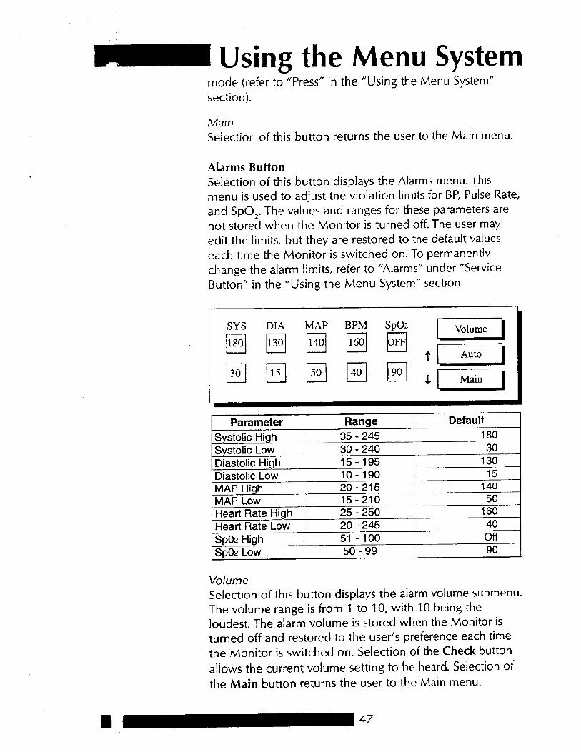
VolumeSelection of this button displays the alarm volume submenu.The volume range is from 1 to 10, with 10 being theloudest. The alarm volume is stored when the Monitor isturned off and restored to the user’s preference each timethe Monitor is switched on. Selection of the Check buttonallows the current volume setting to be heard. Selection ofthe Main button returns the user to the Main menu.
- 100 Off50 PO2 Low
51 iigh.I--- -__..__- I- 245 40
I
20 I””4fin- I
u:-L.-L----
25 250“ICII^_.& 1AP Low 15-210 50
2G 140- 20 _ iigh. . .ill-190 15
. w-.1,._
- 240 I 3015-195 130
- 24530
N
35
t
bMAP
I 180
Diastolic: I nw
I Parameter Range DefaultSystolic HighSystolic LowDiastolic High
SYS DIA
cl130
MAP BPM
cl50
SpO,. The values and ranges for these parameters arenot stored when the Monitor is turned off. The user mayedit the limits, but they are restored to the default valueseach time the Monitor is switched on. To permanentlychange the alarm limits, refer to “Alarms” under “ServiceButton” in the “Using the Menu System” section.
- Using the Menu Systemmode (refer to “Press” in the “Using the Menu System”section).
MainSelection of this button returns the user to the Main menu.
Alarms ButtonSelection of this button displays the Alarms menu. Thismenu is used to adjust the violation limits for BP, Pulse Rate,and
-48
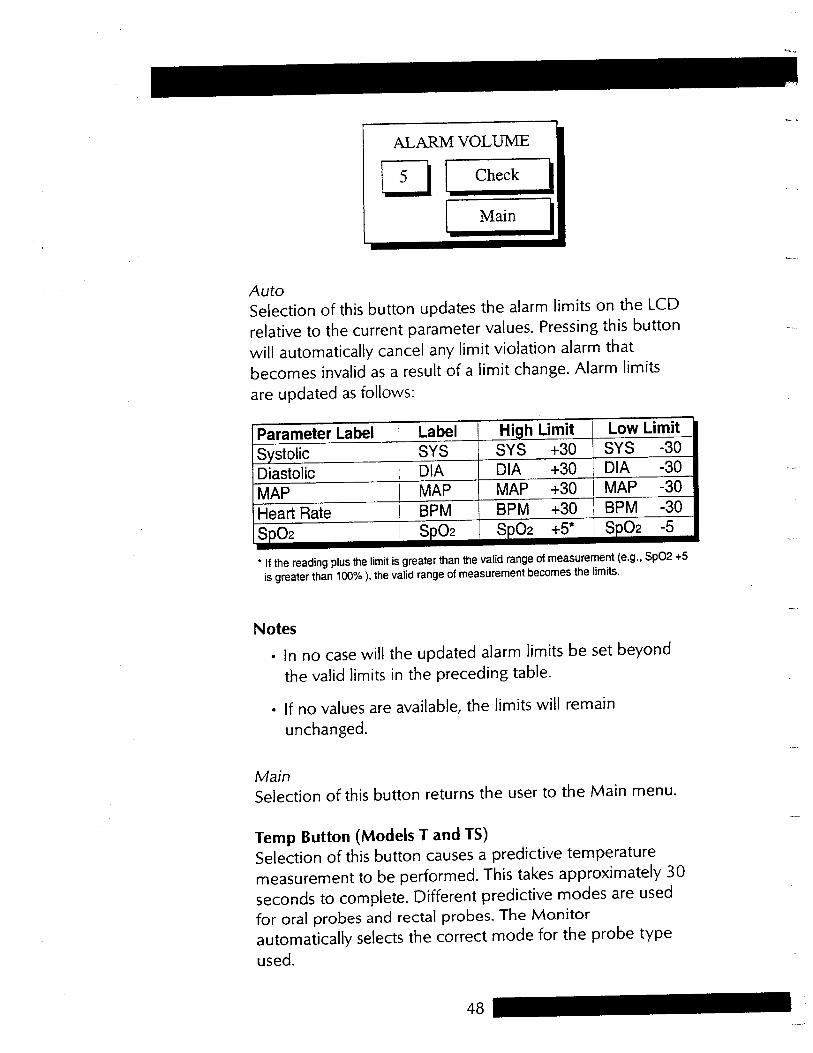
), the valid range of measurement becomes the limits.
Notes
l In no case will the updated alarm limits be set beyondthe valid limits in the preceding table.
l If no values are available, the limits will remainunchanged.
MainSelection of this button returns the user to the Main menu.
Temp Button (Models T and TS)Selection of this button causes a predictive temperaturemeasurement to be performed. This takes approximately 30seconds to complete. Different predictive modes are usedfor oral probes and rectal probes. The Monitorautomatically selects the correct mode for the probe typeused.
+5is greater than 100%
SpO2 the limit is greater than the valid range of measurement (e.g.,
+5* SD02 -5
l If the reading plus
+30 BPM -30SD02
+30 MAP -30BPM
I SD02
MAP ) BPMi MAP
1 DIA -30MAPHeart RateSD02
+30
SYS -30DIA
+30SYS SYSDiastolic DIA
High Limit Low Limit
AutoSelection of this button updates the alarm limits on the LCDrelative to the current parameter values. Pressing this buttonwill automatically cancel any limit violation alarm thatbecomes invalid as a result of a limit change. Alarm limitsare updated as follows:
Parameter Label LabelSystolic

lAuto/lIINow
Pressing this button toggles between Automatic and ManualPrinting modes. The current mode is displayed on Area 3 ofthe LCD. The Automatic mode prints the readings after eachdetermination. The Manual mode, which is the factorydefault mode, requires the user to press the Now button toprint the readings.
NowSelection of this button causes the current readings for the
available parameters to be printed. lf no readings are
available, the message “No reading” is printed for thatparameter. An error message appears if there is no paper inthe printer.
-1
When a rectal (red) probe is used, the pattern on the LEDdisplay looks like this:
Print ButtonSelection of this button displays the Print menu.
Auto/Man
PRINT MENU
determination.will begin. Pressing the button during a Tempdetermination cancels it. While the new determination isbeing performed, the pattern of lines on the temperatureLED display (20) will blink to indicate progress. Oncompletion, the new value will be indicated by thetemperature LED display.Note: When an oral (blue) probe is used, the pattern on theLED display looks like this:
m Using the Menu SystemWhen the Temp button is pressed, any temperature displayfrom a previous reading will be blanked, and a new
-50
1
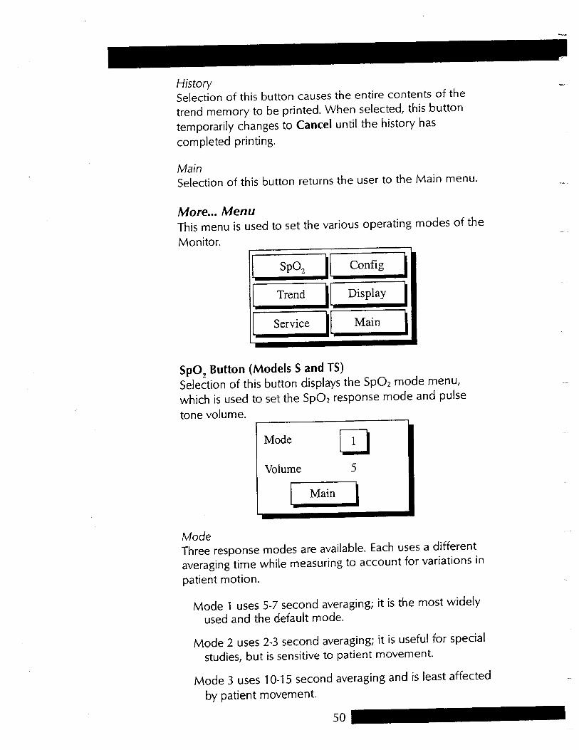
ModeThree response modes are available. Each uses a differentaveraging time while measuring to account for variations inpatient motion.
Mode 1 uses 5-7 second averaging; it is the most widelyused and the default mode.
Mode 2 uses 2-3 second averaging; it is useful for specialstudies, but is sensitive to patient movement.
Mode 3 uses 1 O-l 5 second averaging and is least affectedby patient movement.
1 Main
cl1
Volume 5
SpOZ response mode and pulsetone volume.
Mode
SpOz mode menu,which is used to set the
SpO, Button (Models S and TS)Selection of this button displays the
-
His torySelection of this button causes the entire contents of thetrend memory to be printed. When selected, this buttontemporarily changes to Cancel until the history hascompleted printing.
MainSelection of this button returns the user to the Main menu.
More... MenuThis menu is used to set the various operating modes of theMonitor.

Config mode menu,which allows the Power Save mode and time to be adjusted.
Config ButtonSelection of this button displays the
SpOZ heart rate is available, BP heart rateis used.
l In Mode 3, the heart rate LED and audible beeps aresuppressed as an indication of noncontinuous heartrate monitoring. In Modes 1 and 2, these beeps andflashes occur for each pulse detected.
VolumeThe pulse tone volume can be set in the range of Off to 9.The value Off should be selected if no pulse tone is desired.The volume setting is stored when the Monitor is turned offand is restored to the user’s preference each time theMonitor is switched on.
MainSelection of this button returns the user to the Main menu.
SpOZ heart rate haspriority. If no
. In Mode 3, BP heart rate is used by Trends, Printer, andHost Comm. In Mode 1 and 2,
SpOz heart rate.LEDs and display the ” from the -”
” will bedisplayed.
l Changing from Mode 3 to Mode 1 or 2 will remove BPor
- N LEDs, and
. When changing from Mode 1 or 2 to Mode 3, the heartrate will be removed from the
SpOz-derived heart rate, butallows a heart rate to be displayed from BP (if one isavailable and valid).
. Mode 3 suppresses the
m Using the Menu SystemNotes

-amenu.
Day Mon Year
Accept. Selection of this button produces an advisory to theuser that the trend will be lost when the clock settings arechanged. Choosing Yes will cause the Monitor to accept thenew clock settings and erase the trend memory. ChoosingNo will cause the Monitor to retain the existing clocksettings and the trend memory. Either choice returns theuser to the Main menu.
Main Selection of this button returns the user to the Main
SetMiXI
24-Aug-1997
Hour
_ 1121 20 :
dd/mm/yyyy; however, to avoid confusion the month number hasbeen substituted with a three-letter abbreviation. Leap yearsare calculated automatically.
24-hour format. The date is in the British format of
SelectKnob.
POWER SAVE MENU
TimeSelection of this button allows the operator to change theinternal time and date of the Monitor. The clock, which ismaintained by an internal battery after power down, uses
LEDs). Sleep mode is available only if the Monitor isoperating from its battery. Sleep mode conserves powerwhile the Monitor is not in use. Once the Monitor is inSleep mode, the user can return it to normal operation bytouching any button or the
(LEDs blanked and LCD displaying valuesfrom
Pwr Sav (Sleep Mode)Selection of this button allows the operator to specify thetime, in minutes, that elapses before the Monitor goes into“sleep” mode

pz--y1pi&--) rYizi-Newer_]
-..---- ___ ___ ___ ___ II:52 __ . . -_ _ __ _ __ _ __ _ __ _ II:47_-. _ __ _ __ _ __ _ __ _ __ _ II:42 _-. - -- _ __ _ __ _ __ _ -_ _ II:37
SpO2 TEMP
I Main I
DisplaySelection of this button allows the operator to view thetrend data.Note: If the trend data have been lost (e.g., if the clocksettings have been changed), the message “Trend Empty”will appear instead of the Newer, Older, and Print pagebuttons.
TIME SYS DIA MAP BPM
1[ Print All
1/_ Clear 1 1 Display
I
ROTOR BEEPVolume 3
MainSelection of this button returns the user to the Main menu.
Trend ButtonSelection of this button displays the Trend mode menu.
SelectKnob.
SelectKnob isturned. The range of adjustment is Off (default) to 9, andthe setting is retained when the Monitor is turned off.Note: The Monitor’s LCD may display the word Rotor forthe
(SelectKnob)Selection of this button displays a panel for setting thevolume of the beep that sounds when the
I Using the Menu SystemRotor

SpOZ data are available) and anyerror or warning messages that may appear. The Displaymode setting is maintained when the Monitor is switchedoff and on.
SpO, nor 3 BP isselected, Area 2 of the LCD will remain blank except for thepulse amplitude bar (if
SpO, or BP data. If neither
thf Main menu.
Display ButtonSelection of this button displays the Display mode menu.This menu is used to specify whether Area 2 of the LCD willdisplay
[Cancel1
MainSelection of this button returns the user to
11 Display
AllSelection of this button prints all the historical data available.When selected, this button temporarily changes to Canceluntil the history has completed printing. Once printing iscomplete, the Cancel button returns back to the Print Allbutton.
.,
-.,d
dmenu.
ClearSelection of this button produces an advisory that the trendwill be lost. Choosing Yes will erase the trend memory.Choosing No will retain the trend memory. This buttondisappears from the menu while printing.
l_---_J
Main Selection of this button returns the user to the Main
._,..l
Print page. Selection of this button causes the displayedinformation to be printed. If no information is available,these buttons will not appear.
Newer and Older. These buttons may be used to moveforward and backward through the recorded data. If noinformation is available, these buttons will not appear.

SelectKnob to selectthe numbers 1, 2, 3, 4 sequentially.
Sp02 is automatically disabled when entering Servicemode.
l Service modes that affect the calibration or alignmentof the instrument are not available to the user. Thesemodes are described in the Service Manual.
1
To access the clinician menu, use the
SpOZ data are available, the pulseamplitude bar will also be displayed.
MainSelection of this button returns the user to the Main menu.
Service ButtonSelection of this button displays a keypad that allows theclinician to access some parts of the Service mode menu.
Notes
.
NIBP readings willbe displayed. If
N/BPWhen this option is checked, the last 3
SpO, data are available,the plethysmograph waveform and the pulse amplitude barwill be displayed.
3
PlethWhen this option is checked and Sp02
clX
4
3 NIBP
4 X cl
SpO2 Pleth
Using the Menu System

1,-
I
56
“F indicator lights.
3 Mins
“C indicator lights. WhenF (Fahrenheit) is selected, the
Temn. Selection of this button displays the temperaturesubmenu, which allows the user to choose the temperaturelabel. When C (Celsius) is selected, the
I Main I
_
TARGET PRESSURE
Default 100
mmHgfor adults and 110 for neonates. When the target pressure ischanged, the next determination will use the new target inflationvalue if no systolic is available. When adjusted under the Clinicianmenu of the Service mode, the target pressure is adjustedpermanently.
mmHg increments. The factory default is 180 mmHg in 5
I
The initial target pressure can be set between 100 and 180
.~ .._
mmHg, and the setting isretained when the Monitor is turned off.
mmHg to 180
Clinician Menu
Press. Selection of this button displays a panel for setting thedefault BP target inflation pressure. Adjusting the default targetpressure will automatically update the current inflation targetpressure and will be used for the next reading. The range ofadjustment is 100

,
More.... Selection of this button displays the More... menu, whichallows the user to permanently change default mode settings.
,
NIBP and temperature systems to be displayed.Selection of OK returns the user to the Clinician menu.
Last Calibration
NIBP: 14-Jul-1997Temp: 14-Jul-1997
whethe.r thetemperature displayed by the Monitor will be representative of amercury-in-glass thermometer used for 3 minutes or 12 minutes,respectively. The algorithm is set in the restricted service menu. Theinitial factory default is 3 minutes.
Info. Selection of this button causes the most recent calibrationdates of the
I-. Selection of this button toggles the temperature displaybetween Celsius and Fahrenheit and produces an advisory that thetrend will be lost. Choosing Yes will cause the Monitor to acceptthe new temperature label and erase the trend memory. ChoosingNo will cause the Monitor to retain the existing temperature label
Using the Menu System
and the trend memory.
TREND WILL BE LOST
OK. Selection of this button returns the user to the Service modemenu.
Note: Also on this panel is an indication of the current temperaturealgorithm (3 Mins or 12 Mins), which tells the user
L or I-r-P-

i58-l
I1( Main
cl
(51Manual
ti
SelectKnob has been inactive for 2 minutes, theMonitor automatically returns to the Quik BP menu.Note: The Monitor must be turned off and then on again toactivate this feature.
Auto BP
Quik BP. Selection of this button displays the message: EnableQuik BP menu? Selection of either Yes, No, or Cancel returns theuser to the More... menu. When Quik BP is enabled, the Quik BPmenu always appears as the first menu when the Monitor is turnedon. Selection of Auto BP starts a series of automatic BPdeterminations. A number at the right of the Auto BP buttonindicates the time interval between each reading. Selection ofManual starts a Manual BP determination. Selection of Mainreturns the Monitor to the Main menu. When Quik BP is enabledand after the
.
Note: The Monitor must be turned off and then on again toactivate this feature.
Print. Selection of this button displays the message: Restore Printmode on power-up? Selection of Yes restores the Print mode tothe default setting (previous user-selected mode) after power-offand returns the Monitor to the More... menu. Selection of Norestores the Print mode to the Manual mode after power-off andreturns the Monitor to the More... menu. Selection of Cancelreturns the Monitor to the More... menu.Note: The Monitor must be turned off and then on again toactivate this feature.
.
Y’es,overrides the default setting by clearing all trends on power-up andreturns the Monitor to the More... menu. Selection of No retainsthe default setting by saving all trends after power-off and returnsthe Monitor to the More... menu. Selection of Cancel returns theuser to the More... menu.
.-dAutomatically clear trend on power-up? Selection of either Trend. Selection of this button displays the message:

1
Main. Selection of this button returns the user to the Main menu.
Silence. Selection of this button will cause all alarms except theFAILSAFE alarm to be muted. A confirmation menu will appear inArea 2 of the LED. Selection of either Yes or No returns the user tothe Clinician mode menu. If silence is confirmed, the Alarm Silencebutton (11) illuminates and alarms are permanently muted. If silenceis not confirmed, the alarm will be audible.Caution: Alarms will be muted until either the Monitor is switchedoff and on again or the Alarm Silence button (11) is pressed.
I Cancel
11 Save
11 Reset
J
t
SYS DIA
cl130
BPM
q160
q40
Se!ectionof Reset changes all alarm limits back to the factory defaults andreturns the Monitor to the More... menu. Selection of Savepermanently saves the user-selected alarm limits and returns theMonitor to the More... menu. Selection of Cancel returns the Monitorto the More... menu.Note: The Monitor must be turned off and then on again to activatethis feature.
_ Using the Menu SystemSet BP. Selection of this button displays the message: Restore BPmode on power-up? Selection of Yes restores the BP mode toprevious user-selected mode after power-off and returns the Monitorto the More... menu. Selection of No restores the BP mode to thedefault setting of Manual after power-off and returns the Monitor tothe More... menu. Selection of Cancel returns the Monitor to theMore... menu.Note: The Monitor must be turned off and then on again to activatethis feature.
A/arms. Selection of this button displays the message: Enter alarmconfiguration mode? Selection of No returns the Monitor to theMore... menu. Selection of Yes brings up the Alarms menu.

“FI!Z 0.2 “C; + 0.1
“C; 88.0 “F.l “F
Min: 31 “C; 108.0
f 3.5%
“Fahrenheit (F)“Celsius (C)
Max: 42.2
beats/min (neonate)200 30 to beats/min (adult)200 30 to
mmHg (neonate)mmHg (adult)
150 to 165
s (neonate)
300 to 330
s (adult)85
mmHg)
120
mmHg,standard deviation 18
15
AAMI/ANSI standard SP-10(mean error
TemDeratureScale
Range
Probe Accuracy
Meets or exceeds
(mmHg) Systolic MAP DiastolicAdult 30-245 15-215 10-195Neonate 40-140 30-115 20 -100
Blood Pressure Accuracy
Maximum Determination Time
Overpressure Cutoff
Pulse Rate Range
Pulse Rate Accuracy
mmHg (neonate)
Blood Pressure MeasurementRange
mmHg (adult)100 to 140
mmHg (neonate)
100 to 250
& 15 mmHg (adult)
110+ 15
mmHg (neonate)
180
mmHg (adult)0 to 140
mmHg increments)
0 to 290
Appendix ATechnical SpecificationsBPCuff Pressure Range
Default Target: Cuff Inflation
Target Cuff Inflation:Adjustment Range(in 5

/11
to 100%
0% to 69%: unspecified
Accuracy2.5 digits3.0 digits3.5 digits2.0 digits2.5 digits3.5 digits3.0 digits3.0 digits3.0 digits3.5 digits2.0 digits2.5 digits
2.0 digits2.0 digits
2.0 digits
62
-’
0%
vi
unspecified
30 seconds typical; 60seconds max
OF:<97OFand> 103
OC:unspecified
> 39.4 “C and < 36.1 “FI!I 1 “F:“F to 103
__,97
“C4 0.6“C: “C to 39.4
lOOoh\NELLCOR SensorOXICLIQ-P pediatric sensorOXIBAND pediatric/infant sensorDURA-Y ear clipOXISENSOR II D-20 pediatric sensorOXICLIQ-N neonatal/adult sensorREFLECTANCE sensorDURASENSOR adultOXIBAND adult/neonatal sensorDURA-Y multisite sensorOXISENSOR R-l 5 adult nasal sensorOXISENSOR II D-25 adult sensorOXICLIQ-A adult sensorOXISENSOR II N-25 neonatal/adult
sensorOXISENSOR II l-20 infant sensorOXISENSOR II D-25L adult sensor,
long cable
36.1
- Accuracv (70%
Predictive TemperatureAccuracy
Determination Time
Functional Oxygen Saturation:RangeAccuracy
Adult

s10
s of beingattached to patient
Monitor will detect loss ofpulse from patient and enterno signal state within
s
Pulse Detection
Loss of Pulse
Monitor will detect pulseor enter no signal statewithin 15
beats/min
Audible Indicator Pitch changes withsaturation; volumeselectable from 0 (off) to 9
Waveforms Pulse plethysmographwaveform on LCD gaincompensated
Sensor Disconnect/Disconnect From Patient
Monitor will detectattachment ordisconnection of sensorfrom patient within 5
+3beats/min
Accuracy
NELLCOR’s sensor specifications.
Pulse Rate Range 20 to 250
+3, rather than f2.)Note: Refer to
&l digit to account for the theoretical effect on oximetermeasurements of fetal hemoglobin in neonatal blood (e.g.,N-25 accuracy on neonates is
Appendix ANeonatal AccuracyWhen sensors are used on neonatal subjects asrecommended, the specified accuracy range is increased by
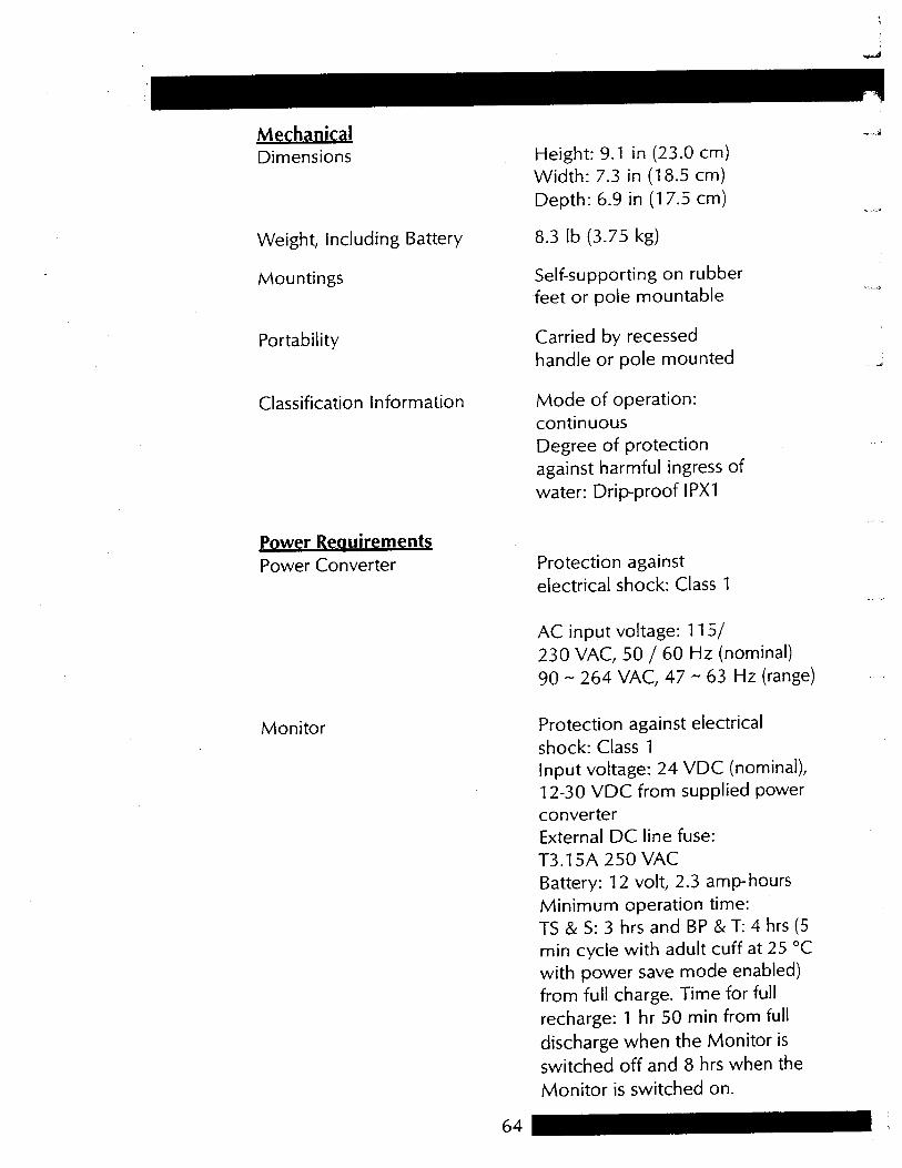
“Cwith power save mode enabled)from full charge. Time for fullrecharge: 1 hr 50 min from fulldischarge when the Monitor isswitched off and 8 hrs when theMonitor is switched on.
T: 4 hrs (5min cycle with adult cuff at 25
& & S: 3 hrs and BP
T3.15A 250 VACBattery: 12 volt, 2.3 amp- hoursMinimum operation time:TS
- 63 Hz (range)
Protection against electricalshock: Class 1Input voltage: 24 VDC (nominal),12-30 VDC from supplied powerconverterExternal DC line fuse:
- 264 VAC, 47/ 60 Hz (nominal)
90
115/230 VAC, 50
ReauirementsPower Converter
Monitor
Protection againstelectrical shock: Class 1
AC input voltage:
lPX1
Power
II
Classification Information Mode of operation:continuousDegree of protectionagainst harmful ingress ofwater: Drip-proof
MechanicalDimensions
Weight, Including Battery
Mountings
Height: 9.1 in (23.0 cm)Width: 7.3 in (18.5 cm)Depth: 6.9 in (17.5 cm)
8.3 lb (3.75 kg)
Self-supporting on rubberfeet or pole mountable
Portability Carried by recessedhandle or pole mounted

IPXl. No harmfuleffects will come of vertically falling dropsof water making contact with the Monitor.
IPXI water and conforms with the IEC 529standard at level of
DlNAMAP@ Compact Monitor isprotected against vertically falling drops of
hPa
0% to 95% noncondensing
Complies with IECPublication 601-l-2 (April1993) Medical ElectricalEquipment, ElectromagneticCompatibility Requirementsand Tests.
The
hPa to 1060
“F)
500
OFto + 122
“C (- 4 “C to + 50 - 20
hPahPa to 1060
to+104”F)
700
“F+5”Cto+40°C(+41 EnvironmentalOperating Temperature
Operating Atmospheric Pressure
Appendix A
Storage Temperature
Storage/TransportationAtmospheric Pressure
Humidity Range
Radio Frequency

SelectKnob cancels the alarm information box which isdisplayed on the LCD. Codes for different procedural andsystem alarms are on the next page.
Failsafe AlarmThe failsafe alarm, which is the most powerful alarm of theCompact Monitor, indicates a serious failure of the Monitor.This alarm occurs immediately upon any failure of a self-testand indicates system failure. When the failsafe alarm occurs,the Monitor disables all features to ensure patient safety.
SpO,) will flashthe most recent reading and an audible alarm will be issued.
Pressing the Alarm Silence switch (causing the integral LEDto be lit) silences the audible alarm for 2 minutes, but thealarm display reading and SILENCE LED indicator willcontinue to flash at the same rate.
System AlarmsSystem alarms alert the operator to certain abnormalconditions or internal system failures. Pressing the
Appendix BAlarm CodesAll alarm indications are accompanied by an audible signalunless Alarm Silence is selected.
A microprocessor system failure will generate a high-pitchedaudible alarm regardless of the setting of the Alarm Silenceswitch.
There are three categories of alarms: patient alarms, systemalarms, and failsafe alarm.
Patient AlarmsPatient alarms include those alarms issued when thepatient’s systolic pressure, diastolic pressure, pulse rate, oroxygen saturation is outside the set limits. Whenever oneof these conditions occurs, the associated display(SYSTOLIC, MAP, DIASTOLIC, PULSE, or

.J,. i
Y
The Priority 1 alarm (i.e., Failsafe) will override any otheralarm. Priority 2 alarms will override only the low batteryalarm. The low battery alarm will not override any otheralarm.
-
_rlc
DINAMAP Compact Monitor are in threepriority levels. They are:
Alarm Priority LevelFailsafe 1Patient and system 2Low battery 3
Hierarchy of AlarmsAlarms in the

!l~~
~~
tes
adjustableC
learO
verpressure detectedyzk!?
%‘,e
PR
ESSUR
E
OV
ER
cNhOange
N
O0
-N
O0
*
INFLT
alarm. V
olume
adjustablesilence
or air leak detected
.
40 seconds
change T
IME
OU
T:
> -
High priority
2 minutes
Clear
Inflation time
No
N33
> 2
adjustablesilence
minutes. M
otion artifact
N33
-H
igh priority
change TIM
EO
UT
: TO
TA
Lalarm
. Volum
e2 m
inutesC
learD
etermination tim
e N
oN
44
1
change TIM
EO
UT
: PR
ES
Salarm
. Volum
esilence
Clear
adjustablem
inute. Motion artifact
N44
>
-H
igh
prio
rity2 m
inu
tes
On
e c
uff p
ressu
re
for
NIB
P FA
ILEDalarm
. Volum
esile
nc
eC
leardeterm
ination due toa
dju
stab
lein
suffic
ien
t sign
al
N55
No
N55
NIB
P
change-
High priority
2 minutes
Unable to m
ake an N
99
No
N99
Se/e&
Kn
ob
Pro
cedu
ral and
E
rror A
larm C
od
es
Alarm
LEDE
ffect of
Effect o
f
Co
de D
isplay
LCD
Display
Audible Tone
and
Vo
lum
eA
larm S
ilence
Clear via
Probable C
auseS
witch

set
> 60
set
Rem
oval of probe beforetem
perature determination
complete
Predictive tem
peraturedeterm
ination
> 30
sensor failure
Tem
perature probe notconnected or inoperable.P
redictive temperature loss
of tissue contact
\lo sensor code detected.
jp0
, sensor not connected.
Sheck or reposition sensor
SpO
, signal.\lo
or very low
I
Pro
bab
le Cau
se
I I . ( .I ( ( f
SelectK
nob
Clear
Clear
Clear
Clear
Clear
;ilence
2m
inutessilence
2m
inutessilence
2m
inutessilence
2m
inutessilence
Effect o
fC
lear via4larm
Silen
Sw
itch
2m
inutes
iigh
priorityalarm
. Volum
eadjustable
High priority
alarm. V
olume
adjustable
High priority
alarm. V
olume
adjustable
High P
riorityalarm
. Volum
eadjustable
Effect o
f
Idjustablealarm
. Volum
eiig
h priority
-
TE
MP
: FA
IL
Au
dib
le To
ne
and
Vo
lum
e
-
TE
MP
: FA
IL
EOO
El1
-
TE
MP
: FA
IL
SpO
, SE
NS
OR
E33 -
NO
5~
0, N
O S
IGN
AL
PO
0 -
change
No
change
No
change
No
change
No
change
LC
D D
escriptio
n
P55
UO
El1
EOO
LEDD
isplay
Procedural and E
rror Alarm
Codes (cont.)
Alarm
Co
de
P55
PO0
E33

Svolum
et,
E, P,
Blank
Error code,
descriptionm
aximum
No effect
No effect
Internal system fault
N,
NIB
P algorithm
returedvalue outside specifiedaccuracy range
Other:
Steady tone,
~il~~~~tesC
lear;am
s;aVbP
dume
~
~~
o~
NG
E
,“,i, Blank
.
-
Code C
hange NO
PA
PE
R
High P
riorityalarm
. Volum
e2 m
inutesC
learP
aper ran out or printer
adjustablesilence
door open
High P
riority
NIB
P m
easurement disabled
FU
NC
TIO
N.
adjustableT
UR
NM
ON
ITO
R O
FF
No N
oP
RIN
TER
C-i, B
lank
TO
O LO
W F
OR
High P
riorityM
ON
ITO
R T
Oalarm
. Volum
eN
o effectN
o effectR
eplace or recharge battery.
NIB
P
adjustablesilence
No effect
measurem
ents available.C
ode Change
battery iconvolum
eB
eep rate increases linearlyas battery discharges
WA
RN
ING
: TH
EB
ATTE
RY
IS
3 beeps everyR
eplace or recharge battery.
No N
oF
lashing10 seconds,
2 minutes
From
onset of alarm. 5
SelectK
no b
LOW
BA
TT
ER
Y,
4larmLE
DE
ffect of
LC
D D
escriptio
nA
ud
ible T
on
eC
odeD
isplayan
d V
olu
me
Alarm
Silen
ceC
lear viaP
rob
able C
ause
Sw
itch
Pro
cedu
ral and
Erro
r Alarm
Co
des
(con
t.)
Effect of

-73I
1
AMPLITUDE
I TIME
BP Determination Sequence
t2
OSCILLATION
k:232
mmHg for neonates depending on the initial targetpressure preset. After inflating the cuff, the Monitor beginsto deflate it and measures systolic pressure, mean pressure,and diastolic pressure. When the diastolic pressure has beendetermined, the Monitor finishes deflating the cuff andupdates the systolic, diastolic, and MAP displays on the
front panel.
The Monitor deflates the cuff one step each time it detectstwo pulsations of relatively equal amplitude. The timebetween deflation steps depends on the frequency of thesematched pulses (pulse rate of the patient). However, if theMonitor is unable to find any pulse within several seconds,it will deflate to the next step. The process of finding twomatched pulses at each step provides artifact rejection dueto patient movement and greatly enhances the accuracy ofthe Monitor. The figure shows the BP determinationsequence.
T
mmHg for adult/pediatric patients, or110
Appendix CPrinciples of Noninvasive Blood PressureDeterminationThe oscillometric method of determining BP isaccomplished by a sensitive transducer which measures cuffpressure and minute pressure oscillations within the cuff.The first determination sequence initially pumps up to a cuffpressure of about 180

I
mmHg abovethe initial target pressure. The maximum pressure allowed insystolic search is limited by the normal range for cuffpressures. In any operating mode, if a patient’s systolicpressure exceeds the inflation pressure of the Monitor, theMonitor will begin normal deflation sequence, detect the
mmHg above the initial target to get better datain the systolic region. If the determination is in an earlystage, the Monitor will inflate the cuff to 50
TltiE
BP Operating Cycle
Systolic SearchIf systolic pressure is not found, the Monitor can search athigher cuff pressures than the initial target pressure. If thedetermination is in a late stage, the Monitor will inflate thecuff to 70
;..,.
PRESSURE
CYCiE TIME
CUFF
./,...TIMEDtiERMlNATlON
/yl:EVALUATION TIME
,,.... :,. ‘NF%:oN
mmHg. The Monitor then deflates thecuff (to zero detected pressure), analyzes the stored data,and updates the front panel displays.
The operating cycle is composed of four parts: inflationtime, deflation time, evaluation time, and wait time. Waittime, which varies from mode to mode, is affected by thecycle time (Auto mode) or operator intervention (Manualmode). The figure shows the Basic Operating Cycle.
At each step the microprocessor stores cuff pressure, thematched pulse amplitude, and the time between successivepulses. The stepped deflation and matched pulse detectioncontinues until diastolic pressure is determined or total cuffpressure falls below 7

mmHg above theimmediately preceding inflation. This additional inflation willoccur only once per determination.
Do not use the auscultatory method to verify the accuracyof the Monitor. Auscultatory method (using cuff andstethoscope) calculates the mean pressure value fromaudible sounds at systolic and diastolic, but the BP functionmethod detects all three values.
Invasive pressure monitoring directly measures the pressureexerted on a transducer and displays this pressure as awaveform. Noninvasive blood pressure monitoring isdependent on the flow of blood through the peripheralcirculation.
mmHgmaximum), and resume normal deflation sequence. Thisadditional inflation will occur only once per determination.
If a previous valid systolic pressure is displayed, and the newsystolic pressure oscillations are compared with theprevious valid determination and the Monitor “thinks” thatthe systolic was not obtained, the Monitor will inflate thecuff to a pressure of an additional 50
Appendix Cabsence of a systolic value, stop deflation, reinflate to ahigher (than initial) inflation pressure (290

DSlOOA320246
IVYarts
allickrodt, Inc.
(UK) CBL700000EC8SpOl Extension Cable
NELLCOR Finger SensorBP Cal KitTemp Cal Plugl Corn act Monitor uniqueNELL&R is a trademark of
(US) 316579Power CableNELLCOR
487206*Power Cable
(UK)
107206*Printer Paper (box of 10)
(US)487205*
Printer Paper (box of 10)
621262*Power Converter (UK)
DINAMAP@ Compact Monitor Service Manual 776856’12 Volt Lead Acid Battery (US) 63313212 Volt Lead Acid Battery (UK) 200000Accessory Pole/Basket 3210Accessory Base 3211Power Converter (US)
DINAMAP@ Compact Monitor Operation Manual 776980’
/ Pediatric Hose 10736612 Foot (approx. 3.7 m) Long Neonatal Hose 107368Oral Temperature Probe 8975Rectal Temperature Probe 8976Temperature Probe Covers (pack of 20) 8815
/ Pediatric Hose 10736524 Foot (approx. 7.3 m) Long Adult
DURA-CUF@ Cuff, Child Pack 269712 Foot (approx. 3.7 m) Long Adult
DURA-CUF@ Cuff, Assortment Cuff Pack 2699DURA-CUF@ Cuff, Thigh 2796DURA-CUF@ Cuff, Large Adult 2791DURA-CUF@ Cuff, Adult 2774DURA-CUF@ Cuff, Small Adult 2779DURA-CUF@ Cuff, Child 2781DURA-CUF@ Cuff, Infant 2783CRlTlKON@ Soft Cuff, Neonatal Type 5 2525CRlTlKON@ Soft Cuff, Neonatal Type 4 2524CRlTlKON@ Soft Cuff, Neonatal Type 3 2523CRITIKON@ Soft Cuff, Neonatal Type 2 2422CRITIKON@ Soft Cuff, Neonatal Type 1 2521CRlTlKON@ Soft Cuff, Thigh 2505CRITIKON@ Soft Cuff, Large Adult 2504CRlTlKON@ Soft Cuff, Adult 2503CRlTlKON@ Soft Cuff, Small Adult 2502CRlTlKON@ Soft Cuff, Child 2501CRITIKON@ Soft Cuff, infant 2500
Appendix DCompatibility Table and Reorder CodesDescription of Compatible Parts Code

.-d_I
.ri
II or2779/2502 end)17cm-25cm
2781/2501 Clippard screwconnectors at Cuff
Small Adult
12cm-19cm
2703f2500 (366 cm) Air HoseGray (made with
Child
8cm-13cmft
Infant
8cm-15cm 2525
ADULT/PEDIATRIC LIMB REFERENCE USE WITH HOSECUFF TYPE CIRCUMFERENCE NUMBER NO.
107361 Adult 12
#5
7cm-13cm 2524#4
6cm-11 cm 2523
107368 Teal Green,Neonatal, 12 ft (366
cm)#3
4cm-8cm 2422#2I1 I I I
I 2521 I I- 6 cmI 3 cm #l
I
USE WITH HOSENO. I
II
REFERENCENUMBERI
LIMBCUFF TYPE CIRCUMFERENCEI NEONATAL

,-81m
ENZOL” enzymaticdetergent (US) or Cidezyme* enzymatic detergent (UK)
l Distilled water
l 10% solution of household bleach (5.25% sodiumhypochlorite) in distilled water
*Trademark
CRlTlKON@ Soft Cuffs without affecting theperformance of the cuff.
l While this procedure is adequate for cleaning/disinfection, it may not remove all stains.
l Do nof immerse hoses.
l Do nof immerse cuffs without prior application of cuff
hose caps.
Materials
l Enzymatic detergent such as
DURA-CUF@Blood Pressure Cuffs and once on
intermediate-level disinfection.
l Apply cuff hose plugs before cleaning.
l The following cleansing procedure was repeated 20times on
. Do not
l Do nof
immerse unit.
clean with isopropyl alcohol or other solvents.
immerse hoses.
Cuff Cleaning and DisinfectionGeneralThe cuff must be thoroughly cleaned with the specifieddetergent before reuse. The additional use of householdbleach as described below provides at least
Appendix FMaintenanceCleaning the MonitorThe Monitor and accessories are to be kept clean and usedaccording to the instructions provided here and in theService Manual.
The exterior of the Monitor may be wiped clean with a softcloth slightly dampened with mild detergents.
l Do not

-Irl
For additional information on infection control procedures,contact Critikon Technical Support.
PrinterIf the print quality is reduced, the print head can be cleanedwith a cotton swap saturated with isopropyl alcohol. Forpreventive maintenance, clean the print head once amonth.
Temperature Devices
l The probe holder and temperature calibration plug maybe removed and cleaned with a mild detergent. Theprobe holder may be immersed during cleaning.
l Do not immerse the temperature calibration plug.
soft-bristled brush to loosen particles. Rinse with copiousamounts of distilled water. Repeat until no visiblecontamination remains. For soil on the hook part of theclosure, use a soft-bristled brush to remove the material,and rinse with copious amounts of distilled water. Repeatuntil no visible contamination remains.
Spray the 10% bleach solution on the affected area untilthe area is saturated. Allow the cuff to sit for 5 minutes.
Wipe away any excess solution and rinse the cuff againwith distilled water. Allow 2 hours for drying.
The user has the responsibility to validate any deviationsfrom the recommended method of cleaning anddisinfection.
_i1.
2.
3.
4.
Prepare the enzymatic detergent according to themanufacturer’s instructions and the 10% bleach solution,in separate spray bottles.Spray the detergent liberally on device. If the material isdried on, allow the cuff to sit for 1 minute. For soil onthe soft part of the closure or the cuff itself, wipe thematerial off with a soft cloth. For persistentcontamination on the soft part of the closure, use a
l Soft cloths and soft-bristled brushes
l Spray bottles
Procedure

SpO, SensorsAdhesive sensors are sterile and for single use only.Reusable sensors can be cleaned with a 70% alcoholsolution. Do not immerse the sensor completely in water,solvents, or cleaning solutions (because the connector is notwaterproof). Do not sterilize the sensor by irradiation,steam, or ethylene oxide. If disposable sensors or theirpackaging are damaged, they must be disposed of asadvised in Appendix F.
Storage and Battery CareIf it becomes necessary to store the Monitor for anextended period of time, first fully charge then remove thebattery. Then store the Monitor and the battery in theoriginal packaging materials.
Batteries should always be fully charged before beingplaced in storage. Even after 6 months of storage, a fullycharged battery can retain about 80% of its charge. A fullycharged battery in good condition will provide sufficientpower to operate a Monitor for approximately 3 hours,including temperature and BP measurements made at5-minute intervals.
It is best to keep the battery charged as fully as practicaland never store the Monitor with the battery in a dischargedcondition. When the battery will no longer hold a charge,remove and replace it with one of the same part number.Failure to replace the battery with the same Critikon partnumber may result in shorter battery life.
To charge the battery, insert the plug from the AC-DCpower converter into the external power socket and thenplug the converter into an appropriate AC outlet. Thebattery will charge regardless of the position of anyswitches.
q - 83
Appendix Fl Do not immerse predictive temperature probes. The
probe may be cleaned with an alcohol solution. Use acloth or sponge-just damp, not wet-and avoid gettingany liquid into the interior of the probe.
1844
i
Replacement of DC Line Input Power FuseAt the rear of the Monitor, disconnect the input supply. Inserta flat bladed tool such as a screwdriver or a coin into the slotin the fuse holder and rotate counterclockwise.
Remove the fuse from the holder. Replace the blown fusewith the appropriate type.
_.“i
_-ilifetime of the battery can be extended up to six times.
Replacement batteries may be obtained from Critikon.Note: The replacement part number of the battery is US:63313 or UK: 200000. Do not use other types.
FusesThe Monitor contains two fuses. The low-voltage DC line inputpower fuse is mounted on the rear of the Monitor. Anadditional thermally resettable fuse, which protects the batterycircuit, is fitted inside the Monitor. This fuse does not requireuser intervention.
1200 cycles. This means that by thoughtful usage, the
1
_..,.A
it never becomes more than one third discharged and isfully recharged whenever possible, it can survive up to
If the battery is used in such a way that
i
allowed to completely discharge before being fullyrecharged, the battery should survive around 200recharge cycles.
_-_j
l The expected lifetime of the battery largely depends onthe way in which the Monitor is used. If the battery is
-
Battery charging will take place as long as the Monitor remainsconnected to an external AC power source via the suppliedAC-DC power converter. A battery that is fully discharged canbe fully recharged in 1 hour 50 minutes when the Monitor isswitched off or 8 hours if the Monitor is switched on.
Cautions
l To ensure that the battery will be ready for portableoperation, keep the Monitor connected to a mainssupply whenever possible.
l Repeated failure to fully charge the battery will result ina significant reduction in battery life.

SpO, sensors), are intended for single use andshould be disposed of properly as medical waste.
Other patient applied parts, such as blood pressure cuffs,should be cleaned according to instructions. Inspectreusable applied parts for wear, replace as necessary, anddispose of used product as medical waste.
DINAMAP Compact Monitor Service Manual,available from Critikon.
Disposal of Product WasteAs you use the Compact Monitor, you will accumulate solidwastes that require proper disposal or recycling. Theseinclude batteries, patient applied parts, and packagingmaterial.
BatteriesCaution: Do not incinerate batteries.The sealed, rechargeable backup battery contains lead andcan be recycled. The rechargeable memory battery is ofthe Nickel Metal Hydride form. Discharge this battery priorto disposal. Place the battery in packaging whichelectrically isolates its contents. Do not puncture or placethe battery in a trash compactor. Do not incinerate thebattery or expose it to fire or high temperatures.
Patient Applied PartsCertain patient applied parts, such as those with adhesive(disposable
f eak TestingA leak test of the BP parameter should be performed atleast once a year or when there is doubt about the validityof the pressure readings.
Caution: Refer calibration and leak testing to qualifiedservice personnel. Full calibration details are available inthe
Appendix FReplace the fuse and fuse holder by inserting the fuseholder into the socket and turning clockwise until it locks.
CalibrationCalibration of the Monitor should be checked at least oncea year or when there is doubt about the validity of thereadings.