din standard compliant ball screw (din69051) · 2017-08-31 · a ball screw din standard compliant...
TRANSCRIPT
A15-90
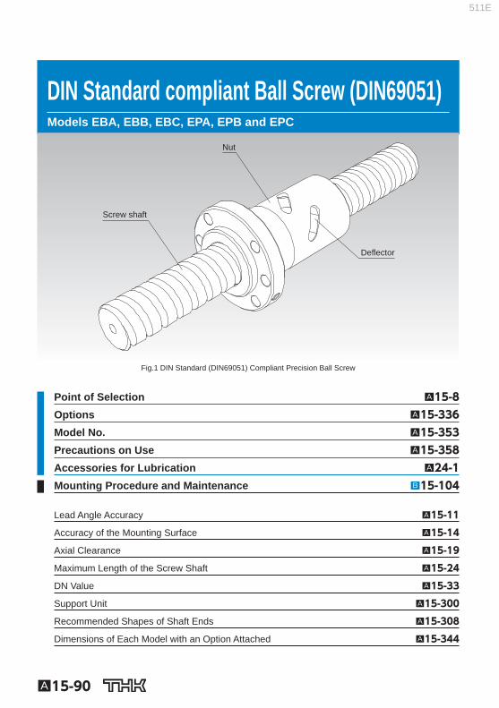
DIN Standard compliant Ball Screw (DIN69051) Models EBA, EBB, EBC, EPA, EPB and EPC
Nut
Screw shaft
Deflector
Fig.1 DIN Standard (DIN69051) Compliant Precision Ball Screw
Point of Selection A15-8 Options A15-336 Model No. A15-353 Precautions on Use A15-358 Accessories for Lubrication A24-1 Mounting Procedure and Maintenance B15-104
Lead Angle Accuracy A15-11
Accuracy of the Mounting Surface A15-14
Axial Clearance A15-19
Maximum Length of the Screw Shaft A15-24
DN Value A15-33
Support Unit A15-300
Recommended Shapes of Shaft Ends A15-308
Dimensions of Each Model with an Option Attached A15-344
511E
A15-91
Ball Screw
DIN Standard compliant Ball Screw (DIN69051)
Structure and Features
In the DIN standard compliant Ball Screw, balls under a load roll in the raceway cut between the screw shaft and the nut while receiving the axial load, travel along the groove of a defl ector embed-ded inside the nut to the adjacent raceway, and then circulate back to the loaded area. Thus, the balls perform infi nite rolling motion. Two types of nuts are available: model EB of oversized-ball preload type or non-preloaded type, and model EP of offset preloaded type.
[Compact] This Ball Screw is compactly built. Because of an internal circulation system using defl ectors, the outer diameter of the nut is 70 to 80% of the conventional double nut and the overall nut length is only 60 to 80% of the return pipe nut.
[Compliant with a DIN standard] The nut fl ange shape, mounting holes and rated load are compliant with DIN69051.
511E
A15-92
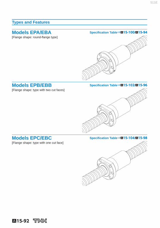
Types and Features
Models EPA/EBA Specifi cation Table⇒A15-100/ A15-94 [Flange shape: round-fl ange type]
Models EPB/EBB Specifi cation Table⇒A15-102/ A15-96 [Flange shape: type with two cut faces]
Models EPC/EBC Specifi cation Table⇒A15-104/ A15-98 [Flange shape: type with one cut face]
511E
A15-93
Ball Screw
DIN Standard compliant Ball Screw (DIN69051)
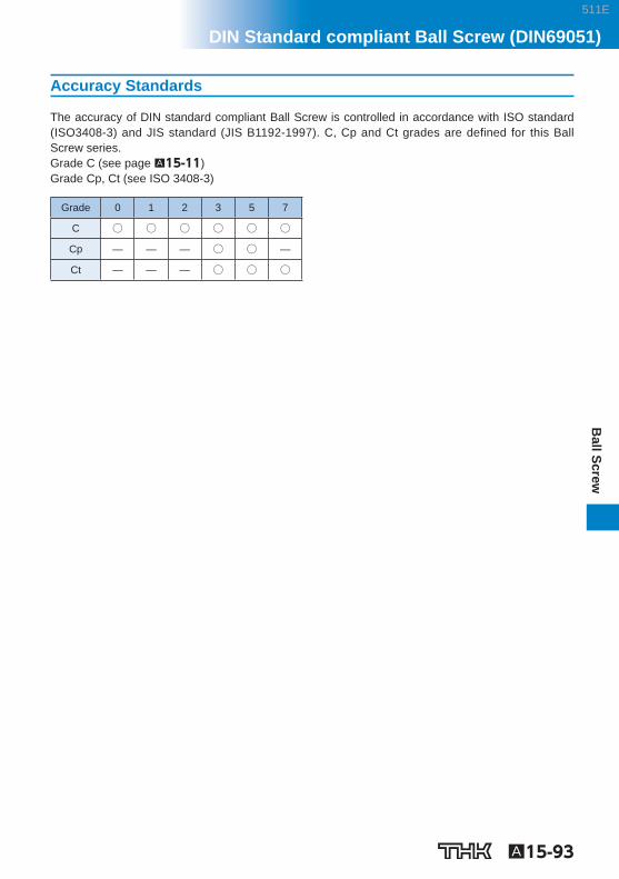
Accuracy Standards
The accuracy of DIN standard compliant Ball Screw is controlled in accordance with ISO standard (ISO3408-3) and JIS standard (JIS B1192-1997). C, Cp and Ct grades are defined for this Ball Screw series. Grade C (see page A15-11 ) Grade Cp, Ct (see ISO 3408-3)
Grade 0 1 2 3 5 7
C ○ ○ ○ ○ ○ ○
Cp — — — ○ ○ —
Ct — — — ○ ○ ○
511E
Model number coding
A15-94 Download data by searching for the corresponding model number on the Technical Support site. https://tech.thk.com
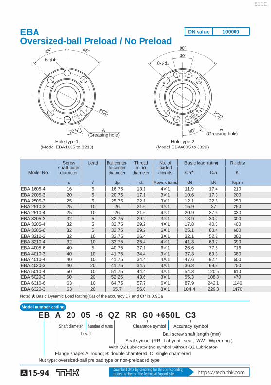
Hole type 1(Model EBA1605 to 3210)
Hole type 2(Model EBA4005 to 6320)
A (Greasing hole)
A (Greasing hole)
PCD
30°90°
30°
PCD
22.5°
45° 45°
8-φ d16-φ d1
Model No.
Screw shaft outer diameter
Lead Ball center-to-center diameter
Thread minor
diameter
No. of loaded circuits
Basic load rating Rigidity
Ca ★ C 0 a K
d ℓ dp d C Rows x turns kN kN N/m EBA 1605-4 16 5 16.75 13.1 4×1 11.9 17.4 210 EBA 2005-3 20 5 20.75 17.1 3×1 10.6 17.3 200 EBA 2505-3 25 5 25.75 22.1 3×1 12.1 22.6 250 EBA 2510-3 25 10 26 21.6 3×1 15.9 27 250 EBA 2510-4 25 10 26 21.6 4×1 20.9 37.6 330 EBA 3205-3 32 5 32.75 29.2 3×1 13.9 30.2 300 EBA 3205-4 32 5 32.75 29.2 4×1 17.8 40.3 400 EBA 3205-6 32 5 32.75 29.2 6×1 25.1 60.4 600 EBA 3210-3 32 10 33.75 26.4 3×1 32.1 52.2 300 EBA 3210-4 32 10 33.75 26.4 4×1 41.3 69.7 390 EBA 4005-6 40 5 40.75 37.1 6×1 26.6 77.5 716 EBA 4010-3 40 10 41.75 34.4 3×1 37.3 69.3 380 EBA 4010-4 40 10 41.75 34.4 4×1 47.6 92.4 500 EBA 4020-3 40 20 41.75 34.7 3×1 36.8 69.3 750 EBA 5010-4 50 10 51.75 44.4 4×1 54.3 120.5 610 EBA 5020-3 50 20 52.25 43.6 3×1 55.3 108.8 470 EBA 6310-6 63 10 64.75 57.7 6×1 87.9 242.1 1140 EBA 6320-3 63 20 65.7 56.0 3×1 104.4 229.3 1470 Note) ★ Basic Dynamic Load Rating(Ca) of the accuracy C7 and Ct7 is 0.9Ca.
Shaft diameter Number of turns
Lead
Clearance symbol Accuracy symbol
Nut type: oversized-ball preload type or non-preloaded type
With QZ Lubricator (no symbol without QZ Lubricator) Seal symbol (RR : Labyrinth seal, WW : Wiper ring.)
Ball screw shaft length (mm)
Flange shape: A: round; B: double chamfered; C: single chamfered
EB A 20 05 -6 QZ RR G0 +650L C3
EBA Oversized-ball Preload / No Preload
DN value 100000
511E

A15-95
Ball Screw
DIN Standard compliant Ball Screw (DIN69051)
Options⇒A15-335
L1
B1H
φD
g6
φ dC φ d
B2
φ D1
φD
0
-0.2
φ D 0 -0.2
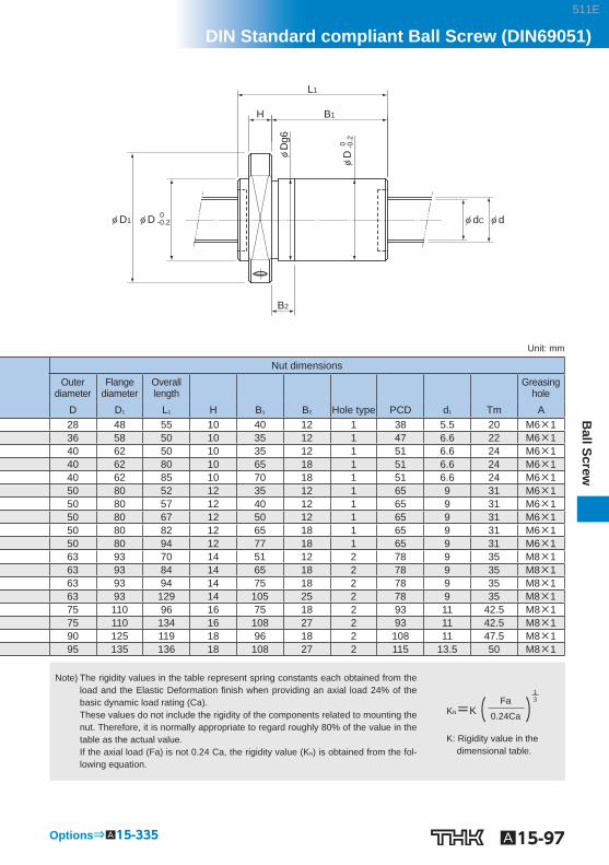
Unit: mm
Nut dimensions Outer
diameter Flange
diameter Overall length Greasing
hole D D 1 L 1 H B 1 B 2 Hole type PCD d 1 A 28 48 55 10 40 12 1 38 5.5 M6×1 36 58 50 10 35 12 1 47 6.6 M6×1 40 62 50 10 35 12 1 51 6.6 M6×1 40 62 80 10 65 18 1 51 6.6 M6×1 40 62 85 10 70 18 1 51 6.6 M6×1 50 80 52 12 35 12 1 65 9 M6×1 50 80 57 12 40 12 1 65 9 M6×1 50 80 67 12 50 12 1 65 9 M6×1 50 80 82 12 65 18 1 65 9 M6×1 50 80 94 12 77 18 1 65 9 M6×1 63 93 70 14 51 12 2 78 9 M8×1 63 93 84 14 65 18 2 78 9 M8×1 63 93 94 14 75 18 2 78 9 M8×1 63 93 129 14 105 25 2 78 9 M8×1 75 110 96 16 75 18 2 93 11 M8×1 75 110 134 16 108 27 2 93 11 M8×1 90 125 119 18 96 18 2 108 11 M8×1 95 135 136 18 108 27 2 115 13.5 M8×1
Note) The rigidity values in the table represent spring constants each obtained from the load and the Elastic Deformation fi nish when providing an axial load 24% of the basic dynamic load rating (Ca). These values do not include the rigidity of the components related to mounting the nut. Therefore, it is normally appropriate to regard roughly 80% of the value in the table as the actual value. If the axial load (Fa) is not 0.24 Ca, the rigidity value (K N ) is obtained from the fol-lowing equation.
K: Rigidity value in the dimensional table.
( )13Fa
0.24CaKN=K
511E

Model number coding
A15-96 Download data by searching for the corresponding model number on the Technical Support site. https://tech.thk.com
Hole type 1(Model EBB1605 to 3210)
Hole type 2(Model EBB4005 to 6320)
A (Greasing hole)
A (Greasing hole)
PCD
Tm Tm
30°90°
30°22.5°
45° 45°
PCD
6-φ d1 8-φ d1
Model No.
Screw shaft outer diameter
Lead Ball center-to-center diameter
Thread minor
diameter
No. of loaded circuits
Basic load rating Rigidity Ca ★ C 0 a K
d ℓ dp d C Rows x turns kN kN N/m EBB 1605-4 16 5 16.75 13.1 4×1 11.9 17.4 210 EBB 2005-3 20 5 20.75 17.1 3×1 10.6 17.3 200 EBB 2505-3 25 5 25.75 22.1 3×1 12.1 22.6 250 EBB 2510-3 25 10 26 21.6 3×1 15.9 27 250 EBB 2510-4 25 10 26 21.6 4×1 20.9 37.6 330 EBB 3205-3 32 5 32.75 29.2 3×1 13.9 30.2 300 EBB 3205-4 32 5 32.75 29.2 4×1 17.8 40.3 400 EBB 3205-6 32 5 32.75 29.2 6×1 25.1 60.4 600 EBB 3210-3 32 10 33.75 26.4 3×1 32.1 52.2 300 EBB 3210-4 32 10 33.75 26.4 4×1 41.3 69.7 390 EBB 4005-6 40 5 40.75 37.1 6×1 26.6 77.5 716 EBB 4010-3 40 10 41.75 34.4 3×1 37.3 69.3 380 EBB 4010-4 40 10 41.75 34.4 4×1 47.6 92.4 500 EBB 4020-3 40 20 41.75 34.7 3×1 36.8 69.3 750 EBB 5010-4 50 10 51.75 44.4 4×1 54.3 120.5 610 EBB 5020-3 50 20 52.25 43.6 3×1 55.3 108.8 470 EBB 6310-6 63 10 64.75 57.7 6×1 87.9 242.1 1140 EBB 6320-3 63 20 65.7 56.0 3×1 104.4 229.3 1470 Note) ★ Basic Dynamic Load Rating(Ca) of the accuracy C7 and Ct7 is 0.9Ca.
Shaft diameter Number of turns
Lead
Clearance symbol Accuracy symbol
Nut type: oversized-ball preload type or non-preloaded type
With QZ Lubricator (no symbol without QZ Lubricator) Seal symbol (RR : Labyrinth seal, WW : Wiper ring.)
Ball screw shaft length (mm)
Flange shape: A: round; B: double chamfered; C: single chamfered
EB B 20 05 -6 QZ RR G0 +650L C3
EBB Oversized-ball Preload / No Preload
DN value 100000
511E
A15-97
Ball Screw
DIN Standard compliant Ball Screw (DIN69051)
Options⇒A15-335
φ D1
B2
φ D 0 -0.2
L1
B1H
0
-0
.2φ
D
φ dC φ d
φD
g6
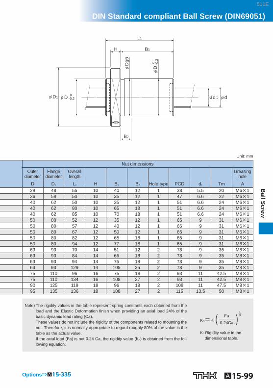
Unit: mm
Nut dimensions Outer
diameter Flange
diameter Overall length
Greasing hole
D D 1 L 1 H B 1 B 2 Hole type PCD d 1 Tm A 28 48 55 10 40 12 1 38 5.5 20 M6×1 36 58 50 10 35 12 1 47 6.6 22 M6×1 40 62 50 10 35 12 1 51 6.6 24 M6×1 40 62 80 10 65 18 1 51 6.6 24 M6×1 40 62 85 10 70 18 1 51 6.6 24 M6×1 50 80 52 12 35 12 1 65 9 31 M6×1 50 80 57 12 40 12 1 65 9 31 M6×1 50 80 67 12 50 12 1 65 9 31 M6×1 50 80 82 12 65 18 1 65 9 31 M6×1 50 80 94 12 77 18 1 65 9 31 M6×1 63 93 70 14 51 12 2 78 9 35 M8×1 63 93 84 14 65 18 2 78 9 35 M8×1 63 93 94 14 75 18 2 78 9 35 M8×1 63 93 129 14 105 25 2 78 9 35 M8×1 75 110 96 16 75 18 2 93 11 42.5 M8×1 75 110 134 16 108 27 2 93 11 42.5 M8×1 90 125 119 18 96 18 2 108 11 47.5 M8×1 95 135 136 18 108 27 2 115 13.5 50 M8×1
Note) The rigidity values in the table represent spring constants each obtained from the load and the Elastic Deformation fi nish when providing an axial load 24% of the basic dynamic load rating (Ca). These values do not include the rigidity of the components related to mounting the nut. Therefore, it is normally appropriate to regard roughly 80% of the value in the table as the actual value. If the axial load (Fa) is not 0.24 Ca, the rigidity value (K N ) is obtained from the fol-lowing equation.
K: Rigidity value in the dimensional table.
( )13Fa
0.24CaKN=K
511E
Model number coding
A15-98 Download data by searching for the corresponding model number on the Technical Support site. https://tech.thk.com
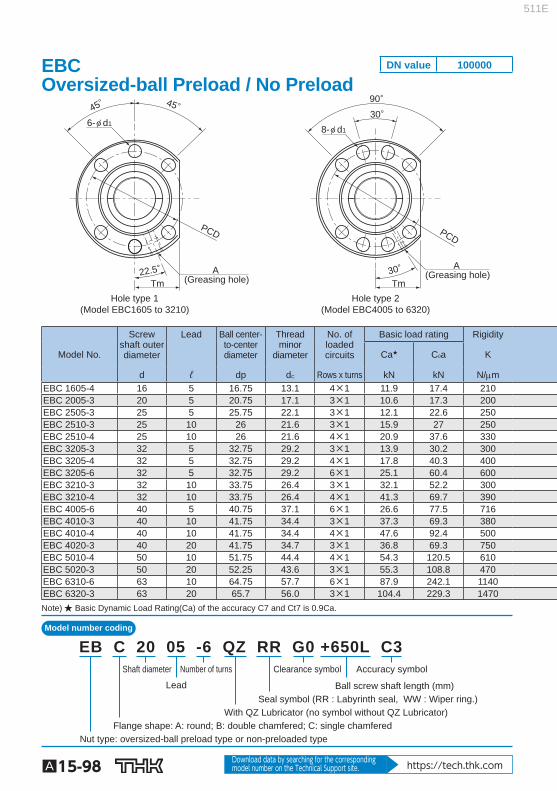
Hole type 1(Model EBC1605 to 3210)
Hole type 2(Model EBC4005 to 6320)
A (Greasing hole)
A (Greasing hole)
PCD
22.5°
45° 45°
Tm Tm
PCD
30°90°
30°
6-φ d18-φ d1
Model No.
Screw shaft outer diameter
Lead Ball center-to-center diameter
Thread minor
diameter
No. of loaded circuits
Basic load rating Rigidity
Ca ★ C 0 a K
d ℓ dp d C Rows x turns kN kN N/m EBC 1605-4 16 5 16.75 13.1 4×1 11.9 17.4 210 EBC 2005-3 20 5 20.75 17.1 3×1 10.6 17.3 200 EBC 2505-3 25 5 25.75 22.1 3×1 12.1 22.6 250 EBC 2510-3 25 10 26 21.6 3×1 15.9 27 250 EBC 2510-4 25 10 26 21.6 4×1 20.9 37.6 330 EBC 3205-3 32 5 32.75 29.2 3×1 13.9 30.2 300 EBC 3205-4 32 5 32.75 29.2 4×1 17.8 40.3 400 EBC 3205-6 32 5 32.75 29.2 6×1 25.1 60.4 600 EBC 3210-3 32 10 33.75 26.4 3×1 32.1 52.2 300 EBC 3210-4 32 10 33.75 26.4 4×1 41.3 69.7 390 EBC 4005-6 40 5 40.75 37.1 6×1 26.6 77.5 716 EBC 4010-3 40 10 41.75 34.4 3×1 37.3 69.3 380 EBC 4010-4 40 10 41.75 34.4 4×1 47.6 92.4 500 EBC 4020-3 40 20 41.75 34.7 3×1 36.8 69.3 750 EBC 5010-4 50 10 51.75 44.4 4×1 54.3 120.5 610 EBC 5020-3 50 20 52.25 43.6 3×1 55.3 108.8 470 EBC 6310-6 63 10 64.75 57.7 6×1 87.9 242.1 1140 EBC 6320-3 63 20 65.7 56.0 3×1 104.4 229.3 1470 Note) ★ Basic Dynamic Load Rating(Ca) of the accuracy C7 and Ct7 is 0.9Ca.
Shaft diameter Number of turns
Lead
Clearance symbol Accuracy symbol
Nut type: oversized-ball preload type or non-preloaded type
With QZ Lubricator (no symbol without QZ Lubricator) Seal symbol (RR : Labyrinth seal, WW : Wiper ring.)
Ball screw shaft length (mm)
Flange shape: A: round; B: double chamfered; C: single chamfered
EB C 20 05 -6 QZ RR G0 +650L C3
EBC Oversized-ball Preload / No Preload
DN value 100000
511E
A15-99
Ball Screw
DIN Standard compliant Ball Screw (DIN69051)
Options⇒A15-335
φ dC φ d
L1
B1H
φD
g6
B2
φ D1 φ D 0 -0.2
φD
0
-0.2
Unit: mm
Nut dimensions Outer
diameter Flange
diameter Overall length Greasing
hole D D 1 L 1 H B 1 B 2 Hole type PCD d 1 Tm A 28 48 55 10 40 12 1 38 5.5 20 M6×1 36 58 50 10 35 12 1 47 6.6 22 M6×1 40 62 50 10 35 12 1 51 6.6 24 M6×1 40 62 80 10 65 18 1 51 6.6 24 M6×1 40 62 85 10 70 18 1 51 6.6 24 M6×1 50 80 52 12 35 12 1 65 9 31 M6×1 50 80 57 12 40 12 1 65 9 31 M6×1 50 80 67 12 50 12 1 65 9 31 M6×1 50 80 82 12 65 18 1 65 9 31 M6×1 50 80 94 12 77 18 1 65 9 31 M6×1 63 93 70 14 51 12 2 78 9 35 M8×1 63 93 84 14 65 18 2 78 9 35 M8×1 63 93 94 14 75 18 2 78 9 35 M8×1 63 93 129 14 105 25 2 78 9 35 M8×1 75 110 96 16 75 18 2 93 11 42.5 M8×1 75 110 134 16 108 27 2 93 11 42.5 M8×1 90 125 119 18 96 18 2 108 11 47.5 M8×1 95 135 136 18 108 27 2 115 13.5 50 M8×1
Note) The rigidity values in the table represent spring constants each obtained from the load and the Elastic Deformation fi nish when providing an axial load 24% of the basic dynamic load rating (Ca). These values do not include the rigidity of the components related to mounting the nut. Therefore, it is normally appropriate to regard roughly 80% of the value in the table as the actual value. If the axial load (Fa) is not 0.24 Ca, the rigidity value (K N ) is obtained from the fol-lowing equation.
K: Rigidity value in the dimensional table.
( )13Fa
0.24CaKN=K
511E
Model number coding
A15-100 Download data by searching for the corresponding model number on the Technical Support site. https://tech.thk.com
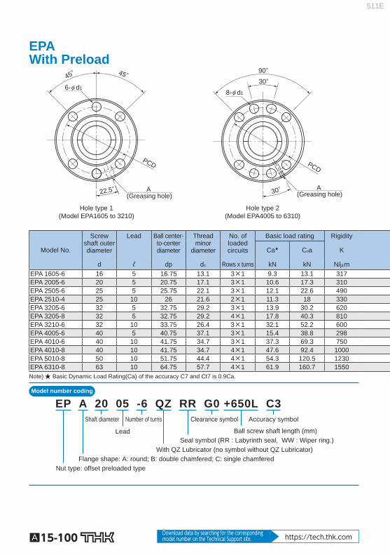
Hole type 1(Model EPA1605 to 3210)
Hole type 2(Model EPA4005 to 6310)
A (Greasing hole)
A (Greasing hole)
PCD
30°90°
30°
PCD
22.5°
45° 45°
8-φ d16-φ d1
Model No.
Screw shaft outer diameter
Lead Ball center-to-center diameter
Thread minor
diameter
No. of loaded circuits
Basic load rating Rigidity
Ca ★ C 0 a K
d ℓ dp d C Rows x turns kN kN N/m EPA 1605-6 16 5 16.75 13.1 3×1 9.3 13.1 317 EPA 2005-6 20 5 20.75 17.1 3×1 10.6 17.3 310 EPA 2505-6 25 5 25.75 22.1 3×1 12.1 22.6 490 EPA 2510-4 25 10 26 21.6 2×1 11.3 18 330 EPA 3205-6 32 5 32.75 29.2 3×1 13.9 30.2 620 EPA 3205-8 32 5 32.75 29.2 4×1 17.8 40.3 810 EPA 3210-6 32 10 33.75 26.4 3×1 32.1 52.2 600 EPA 4005-6 40 5 40.75 37.1 3×1 15.4 38.8 298 EPA 4010-6 40 10 41.75 34.7 3×1 37.3 69.3 750 EPA 4010-8 40 10 41.75 34.7 4×1 47.6 92.4 1000 EPA 5010-8 50 10 51.75 44.4 4×1 54.3 120.5 1230 EPA 6310-8 63 10 64.75 57.7 4×1 61.9 160.7 1550 Note) ★ Basic Dynamic Load Rating(Ca) of the accuracy C7 and Ct7 is 0.9Ca.
Shaft diameter Number of turns
Lead
Clearance symbol Accuracy symbol
Nut type: offset preloaded type
With QZ Lubricator (no symbol without QZ Lubricator)Seal symbol (RR : Labyrinth seal, WW : Wiper ring.)
Ball screw shaft length (mm)
Flange shape: A: round; B: double chamfered; C: single chamfered
EP A 20 05 -6 QZ RR G0 +650L C3
EPA With Preload
511E

A15-101
Ball Screw
DIN Standard compliant Ball Screw (DIN69051)
Options⇒A15-335
L1
B1H
φD
g6
φ dC φ d
B2
φ D1
φD
0
-0.2
φ D 0 -0.2
Unit: mm
Nut dimensions Outer
diameter Flange
diameter Overall length Greasing
hole D D 1 L 1 H B 1 B 2 Hole type PCD d 1 A 28 48 65 10 50 12 1 38 5.5 M6×1 36 58 66 10 51 12 1 47 6.6 M6×1 40 62 66 10 51 12 1 51 6.6 M6×1 40 62 85 10 70 18 1 51 6.6 M6×1 50 80 67 12 50 12 1 65 9 M6×1 50 80 78 12 61 12 1 65 9 M6×1 50 80 112 12 95 18 1 65 9 M6×1 63 93 70 14 51 12 2 78 9 M8×1 63 93 114 14 95 18 2 78 9 M8×1 63 93 138 14 119 18 2 78 9 M8×1 75 110 140 16 119 18 2 93 11 M8×1 90 125 142 18 119 18 2 108 11 M8×1
Note) The rigidity values in the table represent spring constants each obtained from the load and the elastic deformation when providing a preload 8% of the basic dynam-ic load rating (Ca) and applying an axial load three times greater than the preload. These values do not include the rigidity of the components related to mounting the nut. Therefore, it is normally appropriate to regard roughly 80% of the value in the table as the actual value. If the applied preload (Fa0) is not 0.08 Ca, the rigidity value (K N ) is obtained from the following equation.
K: Rigidity value in the dimensional table.
( )13Fa0
0.08CaKN=K
511E
Model number coding
A15-102 Download data by searching for the corresponding model number on the Technical Support site. https://tech.thk.com
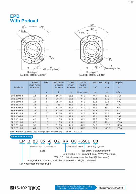
Hole type 1(Model EPB1605 to 3210)
Hole type 2(Model EPB4005 to 6310)
A (Greasing hole)
A (Greasing hole)
PCD
Tm Tm
30°90°
30°22.5°
45° 45°
PCD
6-φ d1 8-φ d1
Model No.
Screw shaft outer diameter
Lead Ball center-to-center diameter
Thread minor
diameter
No. of loaded circuits
Basic load rating Rigidity
Ca ★ C 0 a K
d ℓ dp d C Rows x turns kN kN N/m EPB 1605-6 16 5 16.75 13.1 3×1 9.3 13.1 317 EPB 2005-6 20 5 20.75 17.1 3×1 10.6 17.3 310 EPB 2505-6 25 5 25.75 22.1 3×1 12.1 22.6 490 EPB 2510-4 25 10 26 21.6 2×1 11.3 18 330 EPB 3205-6 32 5 32.75 29.2 3×1 13.9 30.2 620 EPB 3205-8 32 5 32.75 29.2 4×1 17.8 40.3 810 EPB 3210-6 32 10 33.75 26.4 3×1 32.1 52.2 600 EPB 4005-6 40 5 40.75 37.1 3×1 15.4 38.8 298 EPB 4010-6 40 10 41.75 34.7 3×1 37.3 69.3 750 EPB 4010-8 40 10 41.75 34.7 4×1 47.6 92.4 1000 EPB 5010-8 50 10 51.75 44.4 4×1 54.3 120.5 1230 EPB 6310-8 63 10 64.75 57.7 4×1 61.9 160.7 1550 Note) ★ Basic Dynamic Load Rating(Ca) of the accuracy C7 and Ct7 is 0.9Ca.
Shaft diameter Number of turns
Lead
Clearance symbol Accuracy symbol
Nut type: offset preloaded type
With QZ Lubricator (no symbol without QZ Lubricator)Seal symbol (RR : Labyrinth seal, WW : Wiper ring.)
Ball screw shaft length (mm)
Flange shape: A: round; B: double chamfered; C: single chamfered
EP B 20 05 -6 QZ RR G0 +650L C3
EPB With Preload
511E

A15-103
Ball Screw
DIN Standard compliant Ball Screw (DIN69051)
Options⇒A15-335
φ D1
B2
φ D 0 -0.2
L1
B1H
0
-0
.2φ
D
φ dC φ d
φD
g6
Unit: mm
Nut dimensions Outer
diameter Flange
diameter Overall length Greasing
hole D D 1 L 1 H B 1 B 2 Hole type PCD d 1 Tm A 28 48 65 10 50 12 1 38 5.5 20 M6×1 36 58 66 10 51 12 1 47 6.6 22 M6×1 40 62 66 10 51 12 1 51 6.6 24 M6×1 40 62 85 10 70 18 1 51 6.6 24 M6×1 50 80 67 12 50 12 1 65 9 31 M6×1 50 80 78 12 61 12 1 65 9 31 M6×1 50 80 112 12 95 18 1 65 9 31 M6×1 63 93 70 14 51 12 2 78 9 35 M8×1 63 93 114 14 95 18 2 78 9 35 M8×1 63 93 138 14 119 18 2 78 9 35 M8×1 75 110 140 16 119 18 2 93 11 42.5 M8×1 90 125 142 18 119 18 2 108 11 47.5 M8×1
Note) The rigidity values in the table represent spring constants each obtained from the load and the elastic deformation when providing a preload 8% of the basic dynam-ic load rating (Ca) and applying an axial load three times greater than the preload. These values do not include the rigidity of the components related to mounting the nut. Therefore, it is normally appropriate to regard roughly 80% of the value in the table as the actual value. If the applied preload (Fa0) is not 0.08 Ca, the rigidity value (K N ) is obtained from the following equation.
K: Rigidity value in the dimensional table.
( )13Fa0
0.08CaKN=K
511E
Model number coding
A15-104 Download data by searching for the corresponding model number on the Technical Support site. https://tech.thk.com
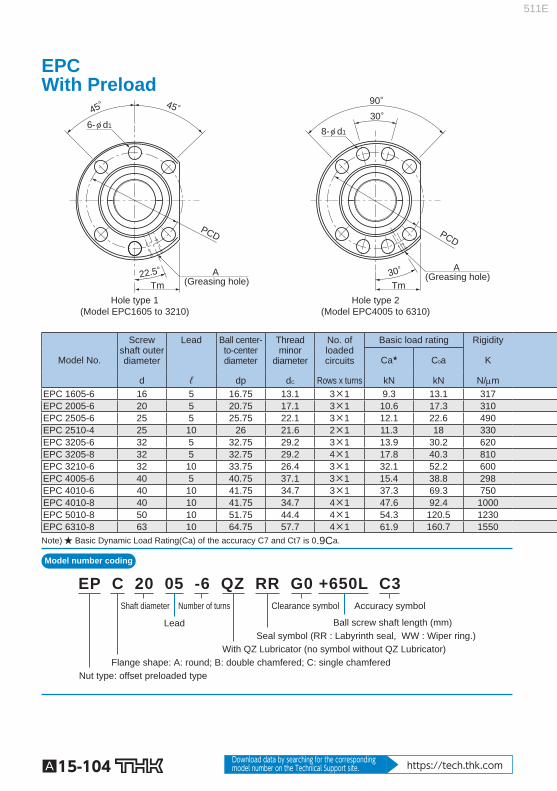
Hole type 1(Model EPC1605 to 3210)
Hole type 2(Model EPC4005 to 6310)
A (Greasing hole)
A (Greasing hole)
PCD
22.5°
45° 45°
Tm Tm
PCD
30°90°
30°
6-φ d18-φ d1
Model No.
Screw shaft outer diameter
Lead Ball center-to-center diameter
Thread minor
diameter
No. of loaded circuits
Basic load rating Rigidity
Ca ★ C 0 a K
d ℓ dp d C Rows x turns kN kN N/m EPC 1605-6 16 5 16.75 13.1 3×1 9.3 13.1 317 EPC 2005-6 20 5 20.75 17.1 3×1 10.6 17.3 310 EPC 2505-6 25 5 25.75 22.1 3×1 12.1 22.6 490 EPC 2510-4 25 10 26 21.6 2×1 11.3 18 330 EPC 3205-6 32 5 32.75 29.2 3×1 13.9 30.2 620 EPC 3205-8 32 5 32.75 29.2 4×1 17.8 40.3 810 EPC 3210-6 32 10 33.75 26.4 3×1 32.1 52.2 600 EPC 4005-6 40 5 40.75 37.1 3×1 15.4 38.8 298 EPC 4010-6 40 10 41.75 34.7 3×1 37.3 69.3 750 EPC 4010-8 40 10 41.75 34.7 4×1 47.6 92.4 1000 EPC 5010-8 50 10 51.75 44.4 4×1 54.3 120.5 1230 EPC 6310-8 63 10 64.75 57.7 4×1 61.9 160.7 1550 Note) ★ Basic Dynamic Load Rating(Ca) of the accuracy C7 and Ct7 is 0.9Ca.
Shaft diameter Number of turns
Lead
Clearance symbol Accuracy symbol
Nut type: offset preloaded type
With QZ Lubricator (no symbol without QZ Lubricator)Seal symbol (RR : Labyrinth seal, WW : Wiper ring.)
Ball screw shaft length (mm)
Flange shape: A: round; B: double chamfered; C: single chamfered
EP C 20 05 -6 QZ RR G0 +650L C3
EPC With Preload
511E
A15-105
Ball Screw
DIN Standard compliant Ball Screw (DIN69051)
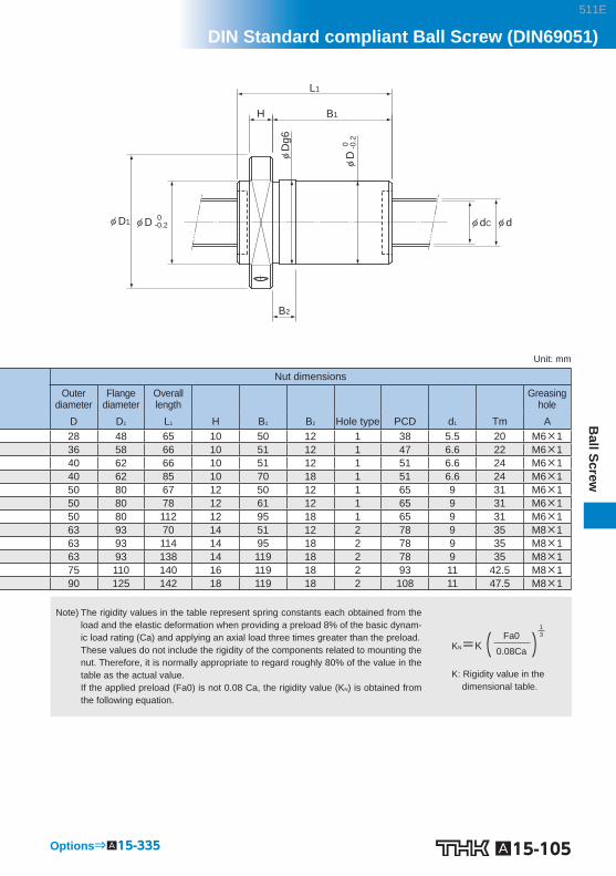
Options⇒A15-335
φ dC φ d
L1
B1H
φD
g6
B2
φ D1 φ D 0 -0.2
φD
0
-0.2
Unit: mm
Nut dimensions Outer
diameter Flange
diameter Overall length Greasing
hole D D 1 L 1 H B 1 B 2 Hole type PCD d 1 Tm A 28 48 65 10 50 12 1 38 5.5 20 M6×1 36 58 66 10 51 12 1 47 6.6 22 M6×1 40 62 66 10 51 12 1 51 6.6 24 M6×1 40 62 85 10 70 18 1 51 6.6 24 M6×1 50 80 67 12 50 12 1 65 9 31 M6×1 50 80 78 12 61 12 1 65 9 31 M6×1 50 80 112 12 95 18 1 65 9 31 M6×1 63 93 70 14 51 12 2 78 9 35 M8×1 63 93 114 14 95 18 2 78 9 35 M8×1 63 93 138 14 119 18 2 78 9 35 M8×1 75 110 140 16 119 18 2 93 11 42.5 M8×1 90 125 142 18 119 18 2 108 11 47.5 M8×1
Note) The rigidity values in the table represent spring constants each obtained from the load and the elastic deformation when providing a preload 8% of the basic dynam-ic load rating (Ca) and applying an axial load three times greater than the preload. These values do not include the rigidity of the components related to mounting the nut. Therefore, it is normally appropriate to regard roughly 80% of the value in the table as the actual value. If the applied preload (Fa0) is not 0.08 Ca, the rigidity value (K N ) is obtained from the following equation.
K: Rigidity value in the dimensional table.
( )13Fa0
0.08CaKN=K
511E