dilatancy, brittle strength, and anisotropy of foliated ... · dilatancy, brittle strength, and...
TRANSCRIPT

Dilatancy, brittle strength, and anisotropy of foliated rocks:
Experimental deformation and micromechanical modeling
Geoffrey C. Rawling,1 Patrick Baud,2 and Teng-fong WongDepartment of Geosciences, State University of New York at Stony Brook, Stony Brook, New York, USA
Received 14 February 2001; revised 7 April 2002; accepted 12 April 2002; published 17 October 2002.
[1] Triaxial compression experiments were performed on the Four-mile gneiss. Thebiotite foliation in the Four-mile gneiss results in dilatancy and strength anisotropies,which become more pronounced with increasing confining pressure. Microstructuralobservations indicate that when there is high resolved shear stress on the macroscopicfoliation, dilatancy arises from extensile microcracks nucleated by frictional slip on biotitegrains. Evolution of crack geometry and coalescence are also influenced by the biotitefoliation. Motivated by these observations, a damage mechanics model based on slidingwing cracks was adopted to analyze the anisotropic development of dilatancy and brittlefracture. Frictional coefficients for the sliding cracks are inferred to be comparable to thoseof cleavage surfaces of biotite. The strength anisotropy data of the Four-mile gneiss can beexplained by the variation of the initial damage with the foliation angle. The damagederives from a set of preexisting microcracks with random orientation, and a set ofcleavage cracks in mica grains preferentially oriented along the foliation angle. Hence, theinitial damage is higher for the intermediate angles, and, consequently, the strength issomewhat lower. The observation that the mechanical strengths of a variety of foliatedrocks decrease with increasing mica content can be explained by the same model, with theimplication that the initial damage and mica content are linearly related. The mechanicaland microstructural data show that dilatancy anisotropy may significantly influence theprogressive development of borehole breakout and strain localization. INDEX TERMS: 5104
Physical Properties of Rocks: Fracture and flow; 5112 Physical Properties of Rocks: Microstructure; 7207
Seismology: Core and mantle; KEYWORDS: dilatancy, anisotropy, mica, cracks, damage mechanics
Citation: Rawling, G. C., P. Baud, and T.-f. Wong, Dilatancy, brittle strength, and anisotropy of foliated rocks: Experimental
deformation and micromechanical modeling, J. Geophys. Res., 107(B10), 2234, doi:10.1029/2001JB000472, 2002.
1. Introduction
[2] The phenomenon of mechanical anisotropy hasreceived considerable interest in rock physics and structuralgeology. Bedding in sedimentary rocks, cleavage in slates,and preferred orientation and/or arrangement of mineralsand cracks in crystalline igneous and metamorphic rocks aresome examples of planar anisotropic rock fabrics that leadto mechanical anisotropy. Elastic anisotropy of a rock canbe related to its fabric, a seismic manifestation of which isshear wave splitting [e.g., Brace, 1965; Barroul and Main-price, 1993; Siegesmund et al., 1993]. Textural anisotropycan also result in significant anisotropy of tensile [Nova andZaninetti, 1990; Liao et al., 1997] and compressive [e.g.,Donath, 1964; Borg and Handin, 1966; Vernik et al., 1992a;Shea and Kronenberg, 1993] strength, that may be associ-ated with different failure modes and deformation mecha-
nisms, depending on how stress is applied relative to theanisotropy planes. Illustrative examples were provided byDonath [1964] on slate, Paterson and Weiss [1966] onphyllite, and Kronenberg et al. [1990] on single crystals ofbiotite. These studies have also documented the transition ofcompressive failure mode from kinking, to frictional orplastic slip, to brittle faulting as the angle between theplane of weakness and the compression axis increases.[3] One of the objectives of this work is to address the
interrelationships of textural anisotropy, dilatancy, and themicromechanics of compressive failure. Dilatancy, definedas inelastic volume increase, is universally observed as aprecursor to the inception of shear localization in the brittlefaulting regime [Brace et al., 1966; Paterson, 1978]. Theonset and development of dilatancy are often associatedwith acoustic emission (AE) activity, and it can be traced tothe nucleation and growth of stress-induced cracks that aresubparallel to the maximum compressive stress [Tapponierand Brace, 1976]. These cracks eventually grow to a lengthcomparable to their spacing and interact with one another,leading to macroscopic fault formation and failure [Wong,1982; Kranz, 1983]. It is recognized that the microcracksnucleate from tensile stress concentrations, which may arisefrom frictional sliding along inclined cracks or grain boun-
JOURNAL OF GEOPHYSICAL RESEARCH, VOL. 107, NO. B10, 2234, doi:10.1029/2001JB000472, 2002
1Now at New Mexico Bureau of Geology and Mineral Resources,Socorro, New Mexico, USA.
2Now at Institut de Physique du Globe, Universite de Louis Pasteur,Strasbourg, France.
Copyright 2002 by the American Geophysical Union.0148-0227/02/2001JB000472$09.00
ETG 8 - 1
daries, crystal plasticity (e.g., twinning), or shear deforma-tion of weak phases (such as mica) [Brace et al., 1966;Tapponier and Brace, 1976; Kranz, 1979; Fredrich et al.,1989].[4] Previous studies of dilatancy and micromechanics of
failure have focused on relatively isotropic rocks. To ourknowledge, the onset and development of dilatancy infoliated rocks have not been systematically investigated.Notwithstanding the paucity of laboratory data, assumptionof dilatancy anisotropy has been (implicitly or explicitly)incorporated into the interpretation of borehole breakoutsand in situ stress measurements [e.g., Vernik et al., 1992b].It may also play a significant role in the localization ofstrain in retrograde shear zones [e.g., Gibson, 1990].[5] Our experimental deformation focuses on the Four-
mile gneiss, the strength anisotropy of which was previ-ously investigated by Gottschalk et al. [1990]. They defineda three-dimensional failure envelope with orthorhombiccharacteristics that is related to the symmetry of the foliationand lineation of biotite within the rock. In this study weinvestigated the anisotropic mechanical behavior of theFour-mile gneiss by conducting triaxial compression experi-ments with volumetric strain and AE measurements, as wellas detailed microstructural observations that have yieldednew insight into the micromechanics of dilatancy anddamage evolution in this foliated rock. Two related ques-tions are addressed in this study. Is the critical stress for theonset of dilatancy anisotropic? If so, why and how is itrelated to the peak stress anisotropy?[6] Traditionally the effect of textural anisotropy on
compressive strength has been analyzed by incorporatinga ‘‘plane of weakness’’ into the empirical Coulomb criterion[Jaeger and Cook, 1979] or modified Griffith criterion[Walsh and Brace, 1964]. More refined models have beenproposed [e.g., Horii and Nemat-Nasser, 1986; Kemeny andCook, 1987; Ashby and Sammis, 1990] for the progressivedevelopment of dilatancy and compressive failure in rock.While such damage mechanics models basically capture themicromechanics of the nucleation, propagation and coales-cence of stress-induced microcracks, they have been appliedonly to relatively isotropic rocks. In this study, we adaptedthe damage mechanics model of Ashby and Sammis [1990]to analyze the observed mechanical anisotropy in terms ofcrack nucleation around a preexisting weak phase and theinfluence of the preferred orientation of biotite on subse-quent damage accumulation. Synthesis of our mechanicaldata and those of Shea and Kronenberg [1993] indicates anoverall trend for the brittle strength of a foliated rock todecrease with increasing mica content. The damagemechanics model was also used to interpret this weakeningtrend in terms of the connection between initial damagestate and mica content. The implications of our results forrelated tectonic and geophysical processes will also bediscussed.
2. Mechanical Deformation
2.1. Sample Material and Preparation
[7] A detailed petrographic description and analysis ofthe Four-mile gneiss were given by Gottschalk et al. [1990].The modal composition of the rock is: 46.1% plagioclase,29.0% quartz, 14.8% microcline, 9.0% biotite and 1.0%
muscovite. Plagioclase grains have lengths ranging from 0.1to 2.8 mm. Quartz and microcline grains are subequant,with effective diameters in the ranges 0.05–1.6 mm and0.1–1.1 mm, respectively. Biotite, the predominant phyllo-silicate, occurs as isolated grains, 0.1–2.2 mm in length,and it defines a strong foliation and a lineation within thefoliation. Measured poles to biotite grains define a strongmaxima perpendicular to the macroscopic foliation. Petro-graphically our undeformed samples are indistinguishablefrom those in the previous study.[8] The oriented samples for triaxial compression experi-
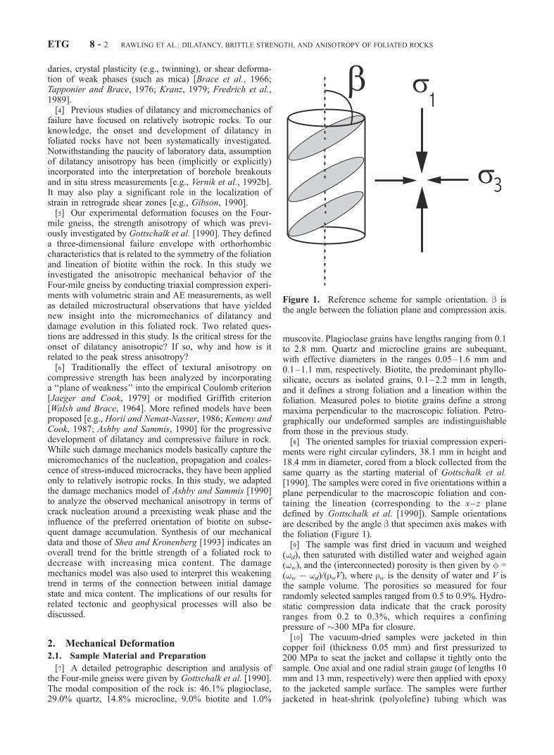
ments were right circular cylinders, 38.1 mm in height and18.4 mm in diameter, cored from a block collected from thesame quarry as the starting material of Gottschalk et al.[1990]. The samples were cored in five orientations within aplane perpendicular to the macroscopic foliation and con-taining the lineation (corresponding to the x– z planedefined by Gottschalk et al. [1990]). Sample orientationsare described by the angle b that specimen axis makes withthe foliation (Figure 1).[9] The sample was first dried in vacuum and weighed
(wd), then saturated with distilled water and weighed again(ww), and the (interconnected) porosity is then given by f =(ww � wd)/(rwV), where rw is the density of water and V isthe sample volume. The porosities so measured for fourrandomly selected samples ranged from 0.5 to 0.9%. Hydro-static compression data indicate that the crack porosityranges from 0.2 to 0.3%, which requires a confiningpressure of �300 MPa for closure.[10] The vacuum-dried samples were jacketed in thin
copper foil (thickness 0.05 mm) and first pressurized to200 MPa to seat the jacket and collapse it tightly onto thesample. One axial and one radial strain gauge (of lengths 10mm and 13 mm, respectively) were then applied with epoxyto the jacketed sample surface. The samples were furtherjacketed in heat-shrink (polyolefine) tubing which was
Figure 1. Reference scheme for sample orientation. b isthe angle between the foliation plane and compression axis.
ETG 8 - 2 RAWLING ET AL.: DILATANCY, BRITTLE STRENGTH, AND ANISOTROPY OF FOLIATED ROCKS
clamped to the steel end spacers with wire. Strain gaugeleads were routed through holes in the tubing and sealedwith silicone sealer. A piezoelectric transducer (PZT-7, 5.0mm diameter, 1 MHz longitudinal resonant frequency) wasattached to one spacer to monitor AE activity during theexperiments.
2.2. Experimental Procedure
[11] We deformed 22 samples (with b = 0�, 30�, 45�, 60�,and 90�) in the conventional triaxial configuration at con-fining pressures (Pc) of 50, 200, and 300 MPa (Table 1).Two additional tests were performed on samples (with b =45�) at Pc = 100 and 150 MPa. The confining pressure wasmonitored with a strain gauge pressure transducer with anaccuracy of 0.5 MPa. The displacement rate was servo-controlled and fixed at 1 mm s�1, corresponding to anominal strain rate of 2.6 � 10�5 s�1. The axial displace-ment was monitored with a displacement transducerbetween the ram and the fixed pressure vessel. The axialload was measured with an external load cell accurate to 1kN. The volumetric strain was calculated using the relationevol = eax + 2erad, where eax and erad are the strains measuredin the axial and transverse directions, respectively. Thestrain measurements have an accuracy of 0.01%, estimatedfrom drift during hydrostatic experiments. The AE signalswere conditioned by a preamplifier and the characteristics ofthe signal were screened with a discriminator [see Wong etal., 1997].
[12] Six samples were deformed at Pc = 200 MPa formicrostructural observation. Three samples (FMG1, FMG5and FMG6) at b = 0�, 45�, and 90�, respectively, weredeformed to near the peak stress, as determined in previousexperiments that ended in brittle failure, and then unloaded.
Three experiments (FMG2, FMG3 and FMG4) were per-formed at b = 45� to different stages of deformation betweenthe onset of dilatancy and peak stress. The deformedsamples were cut in half along the cylinder axis in a planeperpendicular to the foliation. One half was made into astandard optical thin section and the other was made into athick (100 mm) crack section and ion-milled to removesurface-damage. Observations of the crack sections weremade using a JEOL 5300 scanning electron microscope(SEM) with an accelerating voltage of 30 kV in back-scattered electron mode.
2.3. Mechanical Data
[13] All samples in triaxial compression tests failed bythe formation of a single throughgoing fault. After attaininga peak stress, each of the samples underwent an unstablestress drop, except for the 45� sample at 300 MPa (whichhad a small, stable stress drop and the experiment wasstopped at an axial strain of 2.5%). The fault orientationswere at �30� to the sample axis.[14] Volumetric strain and AE measurements provide
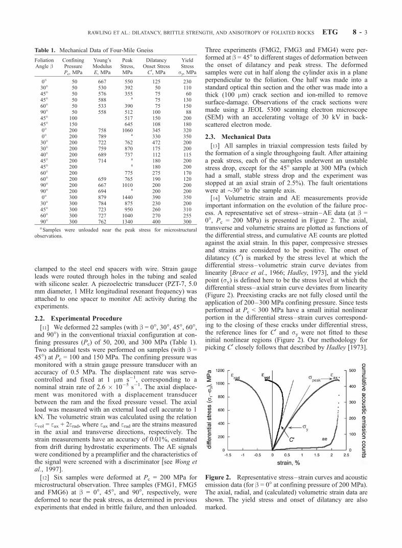
important information on the evolution of the failure proc-ess. A representative set of stress–strain–AE data (at b =0�, Pc = 200 MPa) is presented in Figure 2. The axial,transverse and volumetric strains are plotted as functions ofthe differential stress, and cumulative AE counts are plottedagainst the axial strain. In this paper, compressive stressesand strains are considered to be positive. The onset ofdilatancy (C0) is marked by the stress level at which thedifferential stress–volumetric strain curve deviates fromlinearity [Brace et al., 1966; Hadley, 1973], and the yieldpoint (sy) is defined here to be the stress level at which thedifferential stress–axial strain curve deviates from linearity(Figure 2). Preexisting cracks are not fully closed until theapplication of 200–300 MPa confining pressure. Since testsperformed at Pc < 300 MPa have a small initial nonlinearportion in the differential stress–strain curves correspond-ing to the closing of these cracks under differential stress,the reference lines for C0 and sy were not fitted to theseinitial nonlinear regions (Figure 2). Our methodology forpicking C0 closely follows that described by Hadley [1973].
Table 1. Mechanical Data of Four-Mile Gneiss
FoliationAngle b
ConfiningPressurePc, MPa
Young’sModulusE, MPa
PeakStress,MPa
DilatancyOnset StressC0, MPa
YieldStresssy, MPa
0� 50 667 550 125 23030� 50 530 392 50 11045� 50 576 355 75 6045� 50 588 a 75 13060� 50 533 390 75 15090� 50 558 512 100 8845� 100 517 150 20045� 150 645 108 1800� 200 758 1060 345 3200� 200 789 a 330 35030� 200 722 762 472 20030� 200 759 870 175 20040� 200 689 737 112 11545� 200 714 a 180 20045� 200 a 180 20060� 200 775 275 17060� 200 659 765 190 12090� 200 667 1010 200 20090� 200 694 a 200 2000� 300 879 1440 390 35030� 300 784 875 230 20045� 300 723 950 260 31060� 300 727 1040 270 25590� 300 762 1340 400 300aSamples were unloaded near the peak stress for microstructural
observations.
Figure 2. Representative stress–strain curves and acousticemission data (for b = 0� at confining pressure of 200 MPa).The axial, radial, and (calculated) volumetric strain data areshown. The yield stress and onset of dilatancy are alsomarked.
RAWLING ET AL.: DILATANCY, BRITTLE STRENGTH, AND ANISOTROPY OF FOLIATED ROCKS ETG 8 - 3

[15] The AE activity typically surged at �90% of thepeak stresses in all tests. The general form of the stress–strain curves and AE activity are similar at all b values.Mechanical data from the triaxial tests are compiled in Table1. There is no systematic trend for the amount of dilatancybefore failure to vary with b. However, there is a generaldecrease in the amount of dilatancy with increasing pres-sure.[16] The slope of the elastic reference line for sy deter-
mination (Figure 2) corresponds to Young’s modulus in theaxial direction. It is plotted as a function of b for Pc = 50,200 and 300 MPa in Figure 3. For fixed b, Young’s modulusincreases with increasing Pc. This increase is due to theelastic closure of microcracks. There is an overall decreaseof Young’s modulus with increasing b that levels off athigher angles, in agreement with theoretical predictions[Amadei, 1983; Tien and Tsao, 2000]. Biotite is mostcompressible parallel to [001] [Simmons and Wang,1971], and thus, all other mineral orientations being ran-dom, the rock should be most compressible when b = 90�.This trend is clearest at Pc = 300 MPa because at lowerpressures the open cracks obscure this foliation effect onYoung’s modulus.[17] Figures 4a and 4b show the onset of dilatancy C0 and
peak stress as functions of Pc and b. There is appreciablesample-to-sample variability. This is not unexpected sincesome ambiguity is involved in picking C0: Hadley’s [1973]data for a large number of samples indicate that the variationin C0 from sample to sample at any one confining pressuremay be as much as 100 MPa for Westerly granite and twicethat for the San Marcos gabbro. To our knowledge, this isthe first comprehensive set of data on the concomitantvariation of C0 and brittle strength as functions of foliationorientation and confining pressure. The onset of dilatancyand peak stresses follow qualitatively similar trends inanisotropy. While there is no resolvable anisotropy in peakstress or C0 at Pc = 50 MPa, it is considerable at Pc = 300MPa. The peak differential stresses and their variation withb agree with the results of Gottschalk et al. [1990]. Thegeneral trend of a minimum in the peak stress at b = 30–45�and maxima at b = 0� and 90� is typical of texturallyanisotropic rocks such as shale [Niandou et al., 1997],sandstone [McLamore and Gray, 1967], slate, phyllite,and schist [Donath, 1972] and gneiss and amphibolite[Vernik et al., 1992a].
3. Microstructural Observations of DeformedSamples
[18] In general the deformation microstructure in thegneiss is similar to granite and other low-porosity crystallinerocks deformed in the brittle field [Tapponier and Brace,1976; Wong, 1982; Kranz, 1983; Wong and Biegel, 1985;Hirth and Tullis, 1989; Chang and Haimson, 2000]. Allsamples failed along macroscopic faults formed by thegrowth and coalescence of extensile microcracks with apredominant orientation parallel to the maximum compres-sive stress. The optical microscopy observations of Gott-schalk et al. [1990] on failed samples apply equally well inthis study. However, our SEM and optical microscopyobservations on samples at different stages of deformationprovide new insight into the damage evolution process,especially crack nucleation and propagation around biotitegrains and the effect of the biotite on the subsequent crackcoalescence.
3.1. B = 45�: Nucleation and Propagationof Stress-Induced Cracks
[19] Sample FMG2 was deformed to just beyond theonset of dilatancy C0. The most significant observation inthis sample is that there is evidence for crack growth aroundbiotite grains oriented favorably for frictional slip oncleavage. Figure 5a shows cracks subparallel to the com-
Figure 3. Young’s modulus as function of foliation angleb and confining pressure.
Figure 4. (a) Stress for the onset of dilatancy as functionof foliation angle b and confining pressure. (b) Peak stressas function of foliation angle b and confining pressure.
ETG 8 - 4 RAWLING ET AL.: DILATANCY, BRITTLE STRENGTH, AND ANISOTROPY OF FOLIATED ROCKS

pression axis nucleating at a biotite grain. These are typicalof stress-induced microcracks [Tapponier and Brace, 1976;Kranz, 1983], with very low aperture-to-length ratios,smooth, parallel sides, essentially constant width, and verysharp terminations, often within grains. The biotite grain hasprobably undergone sliding on an open cleavage crack, butslip displacements along such sliding cracks are difficult toresolve even under the SEM [Wong, 1982; Wong andBiegel, 1985]. Shear deformation in the biotite would causea stress concentration at the end of the grain, which wasrelieved by the formation of tensile cracks. Such a scenariowould be most favored at b = 30� and 45�, resulting in anearlier onset of dilatancy at these orientations.[20] At greater strains, crack growth continued to be most
intense around biotite grains oriented favorably for shear.Sample FMG4 was deformed to the stage at which a surgein AE activity indicated the imminent attainment of the peakstress. This sample shows intense zones of cracking aroundthe tips of the grains (Figure 5b). Most of the grainboundaries are cracked. At this stress, kinking has begunin some of the biotite grains. Crack coalescence is moreintense in sample FMG5 which was deformed to near thepeak stress. Figure 5c shows a ‘‘brecciated’’ zone in thissample that has linked two biotite grains.
3.2. B = 0�, 90�: Effect of Foliation on CrackPropagation and Arrest
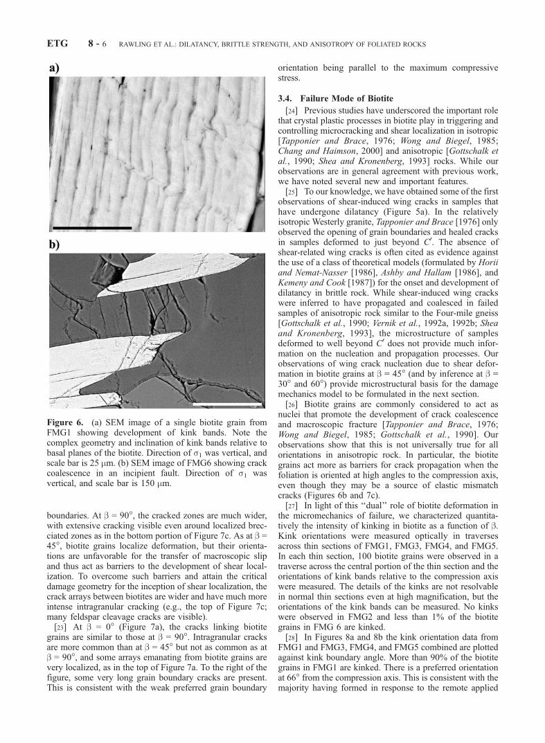
[21] For orientations b = 0� and 90�, biotite is notoriented favorably for slip and typically deforms by kinkingand faulting, respectively. (See Kroanenberg et al. [1990]for results on single crystals). Sample FMG1 (b = 0�) wasdeformed to near the peak stress. Figure 6a shows some ofthe complex kink geometries that develop in biotite grainsoriented at low angles to the compression axis. Noteespecially the formation of voids and the tendency for thekink boundaries to trend diagonally across the basal planes.Sample FMG6 (b = 90�) was deformed to near the peakstress. Intense intragranular cracking in feldspar and quartzgrains which probably resulted from elastic mismatchbetween the compliant biotite and the stiff feldspar or quartzin between can be seen. The elongate biotite grains oftenseem to act as barriers for the linkage of cracks across morethan one grain (Figure 6b).
3.3. Crack Coalescence
[22] The three samples loaded to near the peak stresseswere examined under the petrographic microscope to char-acterize the geometry of crack coalescence. Photomicro-graph mosaics of cracks arrays at (10x magnification) ofFMG1, FMG5, and FMG6 are shown in Figures 7a, 7b, and7c, respectively. The biotite grains appear to exert somedegree of control on the geometry of the growing crackarrays. This is most evident in comparison of b = 45� and90� (Figures 7b and 7c). At b = 45� the cracks betweenbiotite grains are localized in narrow zones that link theends of grains. The upper left of Figure 7b is typical. Grainboundary cracks appear to be more common than intra-granular cracks. This may be due to the weak shapepreferred orientation of the other minerals in the Four-milegneiss. Quartz often occurs as subequant grains arranged inzones subparallel to the foliation, and as a result, thefoliation planes tend to have a higher concentration of grain
Figure 5. (a) SEM image of FMG2 showing nucleation ofwing cracks from the tip of a biotite grain (lighter area atlower part of micrograph). Direction of s1 was vertical, andscale bar is 50 mm. (b) SEM image of FMG4 showingincipient linkage of cracks. Note the grain boundaries aremostly cracked. Direction of s1 was vertical, and scale baris 200 mm. (c) SEM image of FMG5 showing crackcoalescence and brecciation between adjacent biotite grains.Arrays of subvertical cracks are also present. Direction of s1was vertical, and scale bar is 100 mm.
RAWLING ET AL.: DILATANCY, BRITTLE STRENGTH, AND ANISOTROPY OF FOLIATED ROCKS ETG 8 - 5
boundaries. At b = 90�, the cracked zones are much wider,with extensive cracking visible even around localized brec-ciated zones as in the bottom portion of Figure 7c. As at b =45�, biotite grains localize deformation, but their orienta-tions are unfavorable for the transfer of macroscopic slipand thus act as barriers to the development of shear local-ization. To overcome such barriers and attain the criticaldamage geometry for the inception of shear localization, thecrack arrays between biotites are wider and have much moreintense intragranular cracking (e.g., the top of Figure 7c;many feldspar cleavage cracks are visible).[23] At b = 0� (Figure 7a), the cracks linking biotite
grains are similar to those at b = 90�. Intragranular cracksare more common than at b = 45� but not as common as atb = 90�, and some arrays emanating from biotite grains arevery localized, as in the top of Figure 7a. To the right of thefigure, some very long grain boundary cracks are present.This is consistent with the weak preferred grain boundary
orientation being parallel to the maximum compressivestress.
3.4. Failure Mode of Biotite
[24] Previous studies have underscored the important rolethat crystal plastic processes in biotite play in triggering andcontrolling microcracking and shear localization in isotropic[Tapponier and Brace, 1976; Wong and Biegel, 1985;Chang and Haimson, 2000] and anisotropic [Gottschalk etal., 1990; Shea and Kronenberg, 1993] rocks. While ourobservations are in general agreement with previous work,we have noted several new and important features.[25] To our knowledge, we have obtained some of the first
observations of shear-induced wing cracks in samples thathave undergone dilatancy (Figure 5a). In the relativelyisotropic Westerly granite, Tapponier and Brace [1976] onlyobserved the opening of grain boundaries and healed cracksin samples deformed to just beyond C0. The absence ofshear-related wing cracks is often cited as evidence againstthe use of a class of theoretical models (formulated by Horiiand Nemat-Nasser [1986], Ashby and Hallam [1986], andKemeny and Cook [1987]) for the onset and development ofdilatancy in brittle rock. While shear-induced wing crackswere inferred to have propagated and coalesced in failedsamples of anisotropic rock similar to the Four-mile gneiss[Gottschalk et al., 1990; Vernik et al., 1992a, 1992b; Sheaand Kronenberg, 1993], the microstructure of samplesdeformed to well beyond C0 does not provide much infor-mation on the nucleation and propagation processes. Ourobservations of wing crack nucleation due to shear defor-mation in biotite grains at b = 45� (and by inference at b =30� and 60�) provide microstructural basis for the damagemechanics model to be formulated in the next section.[26] Biotite grains are commonly considered to act as
nuclei that promote the development of crack coalescenceand macroscopic fracture [Tapponier and Brace, 1976;Wong and Biegel, 1985; Gottschalk et al., 1990]. Ourobservations show that this is not universally true for allorientations in anisotropic rock. In particular, the biotitegrains act more as barriers for crack propagation when thefoliation is oriented at high angles to the compression axis,even though they may be a source of elastic mismatchcracks (Figures 6b and 7c).[27] In light of this ‘‘dual’’ role of biotite deformation in
the micromechanics of failure, we characterized quantita-tively the intensity of kinking in biotite as a function of b.Kink orientations were measured optically in traversesacross thin sections of FMG1, FMG3, FMG4, and FMG5.In each thin section, 100 biotite grains were observed in atraverse across the central portion of the thin section and theorientations of kink bands relative to the compression axiswere measured. The details of the kinks are not resolvablein normal thin sections even at high magnification, but theorientations of the kink bands can be measured. No kinkswere observed in FMG2 and less than 1% of the biotitegrains in FMG 6 are kinked.[28] In Figures 8a and 8b the kink orientation data from
FMG1 and FMG3, FMG4, and FMG5 combined are plottedagainst kink boundary angle. More than 90% of the biotitegrains in FMG1 are kinked. There is a preferred orientationat 66� from the compression axis. This is consistent with themajority having formed in response to the remote applied
Figure 6. (a) SEM image of a single biotite grain fromFMG1 showing development of kink bands. Note thecomplex geometry and inclination of kink bands relative tobasal planes of the biotite. Direction of s1 was vertical, andscale bar is 25 mm. (b) SEM image of FMG6 showing crackcoalescence in an incipient fault. Direction of s1 wasvertical, and scale bar is 150 mm.
ETG 8 - 6 RAWLING ET AL.: DILATANCY, BRITTLE STRENGTH, AND ANISOTROPY OF FOLIATED ROCKS

stress field, since the orientations of kinks are similar towhat has been observed in experimental studies on slate[Gay and Weiss, 1974] and phyllite [Paterson and Weiss,1966] in which samples were compressed parallel to thefoliation. In FMG5, 21% of the biotite grains are kinked.There are a wide range of orientations, with slightlypreferred orientations at 30� and 60�, and a minimum at45�. This suggests they are mostly a response to local stressperturbations, possibly due to basal slip.
4. Damage Mechanics of Dilatancy and BrittleFailure in Foliated Rocks
[29] Many empirical relations have been advanced todescribe the orientation dependence of strength in aniso-tropic rocks [e.g., McLamore and Gray, 1967; Donath,1972; Gottschalk et al.,1990]. In addition several theoreticalmodels have been proposed. Jaeger [1960] described thesingle plane of weakness and continuously varying shearstrength theories, which involve the variation with directionof the cohesive strength and internal friction parameters ofthe Mohr–Coulomb failure criterion. However, Donath[1972] emphasized that these parameters have no physicalmeaning in terms of fundamental rock properties. Walsh andBrace’s [1964] modified Griffith criterion yields similarpredictions but is based on the orientations and frictioncoefficients of preexisting crack populations and thus iseasily linked to rock properties. Yet these models are strictlyonly criteria for the activation of slip on a critically oriented‘‘plane of weakness’’ or crack and thus do not predict thefailure stress, because, as was first noted by Brace and
Bombolakis [1963], fracture of brittle materials involvesboth the nucleation of cracks and their subsequent growthand coalescence to form a macroscopic fault.[30] The more recent fracture mechanics formulations
attempt to quantify both of these aspects of failure. Themicrostructural observations suggest that slip on favorablyoriented biotite grains leads to crack nucleation that resultsin macroscopic dilatancy (Figure 5a). In many aspects, thisscenario is captured by the ‘‘sliding wing crack’’ model[Brace et al., 1966; Horii and Nemat-Nasser, 1986; Ashbyand Hallam, 1986; Kemeny and Cook, 1987]. If theresolved shear stress on an inclined crack, which may beidentified as a cleavage crack in a biotite grain, exceeds thefrictional strength, slip occurs and tensile stress concentra-tion develops at the tips of the inclined sliding crack (Figure9). Extensile wing cracks nucleate and propagate along adirection subparallel to s1, the maximum principal stress.The initial propagation of a wing crack is stable, in thatstress must be continuously increased for it to extend, butthe mutual interaction of the stress fields of multiple wingcracks may lead to instability, which corresponds to theonset of shear localization and macroscopic fracture [Horiiand Nemat-Nasser, 1986; Sammis and Ashby, 1986;Kemeny and Cook, 1987].
4.1. Onset of Dilatancy: Isotropic and AnisotropicNucleation Conditions
[31] Consider a crack of length 2a inclined at an arbitraryangle g to s1 (Figure 9). When frictional slip occurs on thisinclined crack, the stress concentrations at its tips mayinduce ‘‘wing cracks’’ to nucleate at an angle of 70.5� to
Figure 7. (a) Optical micrograph mosaic of sample FMG1 showing coalescence of kinked biotite grainand crack arrays. Direction of s1 was vertical. (b) Optical micrograph mosaic of sample FMG5 showingcoalescence of cleavage cracks in biotite and wing cracks. Direction of s1 was vertical. (c) Opticalmicrograph mosaic of sample FMG6 showing coalescence of subvertical crack arrays and biotite grainsacting as barriers to the development of shear localization. Direction of s1 was vertical.
RAWLING ET AL.: DILATANCY, BRITTLE STRENGTH, AND ANISOTROPY OF FOLIATED ROCKS ETG 8 - 7
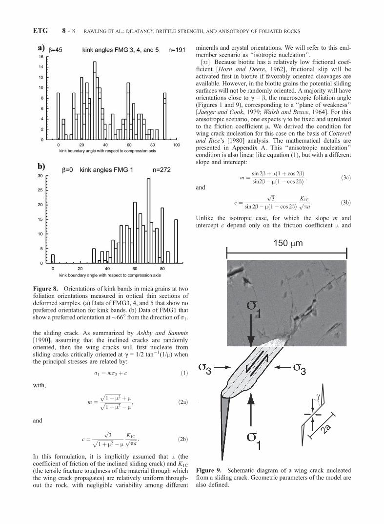
the sliding crack. As summarized by Ashby and Sammis[1990], assuming that the inclined cracks are randomlyoriented, then the wing cracks will first nucleate fromsliding cracks critically oriented at g = 1/2 tan�1(1/m) whenthe principal stresses are related by:
s1 ¼ ms3 þ c ð1Þ
with,
m ¼ffiffiffiffiffiffiffiffiffiffiffiffiffi1þ m2
pþ mffiffiffiffiffiffiffiffiffiffiffiffiffi
1þ m2p
� m; ð2aÞ
and
c ¼ffiffiffi3
pffiffiffiffiffiffiffiffiffiffiffiffiffi1þ m2
p� m
K1Cffiffiffiffiffiffipa
p : ð2bÞ
In this formulation, it is implicitly assumed that m (thecoefficient of friction of the inclined sliding crack) and K1C
(the tensile fracture toughness of the material through whichthe wing crack propagates) are relatively uniform through-out the rock, with negligible variability among different
minerals and crystal orientations. We will refer to this end-member scenario as ‘‘isotropic nucleation’’.[32] Because biotite has a relatively low frictional coef-
ficient [Horn and Deere, 1962], frictional slip will beactivated first in biotite if favorably oriented cleavages areavailable. However, in the biotite grains the potential slidingsurfaces will not be randomly oriented. A majority will haveorientations close to g = b, the macroscopic foliation angle(Figures 1 and 9), corresponding to a ‘‘plane of weakness’’[Jaeger and Cook, 1979; Walsh and Brace, 1964]. For thisanisotropic scenario, one expects g to be fixed and unrelatedto the friction coefficient m. We derived the condition forwing crack nucleation for this case on the basis of Cotterelland Rice’s [1980] analysis. The mathematical details arepresented in Appendix A. This ‘‘anisotropic nucleation’’condition is also linear like equation (1), but with a differentslope and intercept:
m ¼ sin 2bþ m 1þ cos 2bð Þsin2b� m 1� cos 2bð Þ ; ð3aÞ
and
c ¼ffiffiffi3
p
sin 2b� m 1� cos 2bð ÞK1Cffiffiffiffiffiffipa
p : ð3bÞ
Unlike the isotropic case, for which the slope m andintercept c depend only on the friction coefficient m and
Figure 8. Orientations of kink bands in mica grains at twofoliation orientations measured in optical thin sections ofdeformed samples. (a) Data of FMG3, 4, and 5 that show nopreferred orientation for kink bands. (b) Data of FMG1 thatshow a preferred orientation at�66� from the direction of s1.
Figure 9. Schematic diagram of a wing crack nucleatedfrom a sliding crack. Geometric parameters of the model arealso defined.
ETG 8 - 8 RAWLING ET AL.: DILATANCY, BRITTLE STRENGTH, AND ANISOTROPY OF FOLIATED ROCKS

toughness parameter K1C=ffiffiffiffiffiffipa
p, the parameters in the
anisotropic case depend also on the foliation angle b. Notealso that equations (3a) and (3b) should only be applied tointermediate foliation orientations, because they predictphysically unrealistic stress states for both b = 0 and b >tan�1(1/m).[33] If we identify macroscopic dilatancy with the nucle-
ation of wing cracks, then the onset of dilatancy C0 shouldcorrespond to the critical stress state given by equation (1).Since the stresses follow linear trends, the slope andintercept can be determined by linear regression. From theslope m, we can use either equation (2a) or (3a) to infer thecoefficient m for frictional sliding on the inclined cracksurface. Values inferred from the isotropic model are com-piled in Table 2 and are shown as dark circles in Figure 10.For comparison, values for the relatively isotropic Westerlygranite and San Marcos gabbro are also shown.
[34] Our microstructural observations suggest that theanisotropic nucleation model is more appropriate for sam-ples with intermediate foliation angles (b = 30�, 45�, and60�). As discussed above, for orientations b = 0� and 90�biotite is not oriented favorably for slip and typicallydeforms by kinking and faulting, respectively. As shownin Figure 10, m values (light circles) inferred from equation(3a) are somewhat lower than those calculated from theisotropic model and vary over a smaller range (Table 2). Forall angles, the inferred values for the Four-mile gneiss (with9% biotite) are lower than that of Westerly granite (with 5%biotite). For the intermediate angles, our inferred m valuesare comparable to that of San Marcos gabbro (with 12%biotite) and within the range (0.26–0.31) determined forfrictional sliding on cleavage surfaces of biotite [Horn andDeere, 1962]. Relatively low friction on mica cleavagesallows dilatancy to initiate at somewhat lower stresses.[35] Using m values so inferred we can next use equation
(2b) or (3b) to infer from the intercept c the parameterK1C=
ffiffiffiffiffiffipa
p. Alternatively we can use the brittle strength data
to infer the fracture mechanics parameter. Since recentstudies of Baud et al. [2000a, 2000b] have shown that thislatter approach is more robust, we have adopted theirmethodology for the inference of the fracture mechanicsparameters, to be discussed in the next section.
4.2. Critical Condition for Crack Coalescence andBrittle Failure
[36] A number of damage mechanics models [e.g., Horiiand Nemat-Nasser, 1986; Kemeny and Cook, 1987; Ashbyand Sammis, 1990] have been formulated to describe thepropagation and coalescence of wing cracks. Specific differ-ences among the various micromechanical models werereviewed by Fredrich et al. [1990] and Kemeny and Cook[1991], but their predictions are qualitatively similar. After
initial nucleation, wing cracks propagate stably along atrajectory subparallel to s1. The stable growth of a multi-plicity of wing cracks results in progressive development ofdilatancy. When the stress-induced cracks achieve a criticalgeometry, crack coalescence and shear localization occur.The critical stress state at which this instability occurs issensitively dependent on the preexisting damage, charac-terized by abundance of potential sliding crack surfaces andthe size distribution.[37] For mathematical convenience we have adopted
Ashby and Sammis’ [1990] 2-dimensional damage mechan-ics model to analyze the development of brittle failure andthe influence of mica content and foliation orientation onbrittle strength. The key damage parameter in this model isthe crack density D = p(‘ + a cos g)2NA, where ‘ is thelength of the wing crack, and NA is the number of slidingcracks per unit area initially present. Before wing cracksnucleate, the length ‘ = 0 and therefore the initial damage isgiven by Do = p(a cos g)2NA. With the progressive develop-ment of dilatancy, the principal stresses evolve with damagein accordance with equation (17) of Ashby and Sammis[1990]:
s1 ¼ C1 þC4
ffiffiffiffiffiffiffiffiffiffiffiffiD=Do
p� 1
� �
1þffiffiffiffiffiffiffiffiffipDo
pffiffiffiffiffiffiffiffiffiffiffiffiD=Do
p� 1
1�ffiffiffiffiD
p
26664
37775
s3 þ
ffiffiffiffiffiffiffiffiffiffiffiffiD=Do
p� 1þ 0:1=cos g
� �1=2
1þffiffiffiffiffiffiffiffiffipDo
pffiffiffiffiffiffiffiffiffiffiffiffiD=Do
p� 1
1�ffiffiffiffiD
p
C4ffiffiffiffiffiffiffiffiffiffifficos g
pK1Cffiffiffiffiffiffipa
p ð4Þ
where C1¼ðffiffiffiffiffiffiffiffiffiffiffi1þm2
pþmÞ=ð
ffiffiffiffiffiffiffiffiffiffiffiffi1þm2
p�mÞ and C4 ¼
ffiffiffiffiffi30
pcosg=
ðffiffiffiffiffiffiffiffiffiffiffiffi1þm2
p�mÞ. Although microcracks may be nucleated from
Table 2. Parameters Inferred From Damage Mechanics Model
FoliationAngle b
FrictionCoefficient ma
InitialDamage Do
Normalized FractureToughness K1C=
ffiffiffiffiffiffi�a
p, MPa
0� (0.38) 0.082 9330� 0.26 (0.28) 0.095 8045� 0.24 (0.23) 0.110 9560� 0.22 (0.30) 0.093 9090� (0.39) 0.088 88aValues with and without brackets were derived using the isotropic and
anisotropic nucleation conditions, respectively.
Figure 10. Friction coefficient as a function of foliationangle b inferred from dilatancy onset data on the basis of thewing crack model using isotropic and anisotropic nucleationconditions. Friction coefficients for Westerly granite (fromdata of Brace et al. [1966]) and San Marcos gabbro (fromdata of Hadley [1973]) were calculated using the isotropicnucleation model. For comparison, experimental values forrock friction [Byerlee, 1978] and biotite friction [Horn andDeere, 1962] are shown.
RAWLING ET AL.: DILATANCY, BRITTLE STRENGTH, AND ANISOTROPY OF FOLIATED ROCKS ETG 8 - 9

sliding cracks of specific orientations, the ultimate failureand instability arise from the interaction and coalescence ofnumerous microcracks nucleated from sliding cracks with arange of g values. It is implicitly assumed in the derivationof the above equation that the cooperative effects of themultiplicity of cracks are approximated by choosing an‘‘effective’’ value of g = 45�.[38] If one specifies thematerial parametersDo; KIC=
ffiffiffiffiffiffipa
p
and m, then the evolution of the principal stress s1 as afunction of damage D at a fixed confining stress s3 can becalculated using equation (4). In the brittle regime, thedamage accumulation is manifested first by strain hardeningand then by strain softening (Figure 11a). The critical stress
state at which instability occurs is identified as the peakvalue at the transition from hardening to softening for eachcurve.[39] Repeating the calculation for different values of
fixed s3 allows one to map out the brittle failure envelopein the principal stress space. To a first approximation thisfailure envelope for the wing crack model [Horii andNemat-Nasser, 1986; Ashby and Sammis, 1990; Fredrichet al., 1990; Kemeny and Cook, 1991; Baud et al., 2000a,2000b] can be described by a linear relation
s1 ¼ A m;Doð Þs3 þ B m;Doð ÞKIC=ffiffiffiffiffiffipa
pð5Þ
If triaxial compression data for the onset of dilatancy andpeak stress follow the linear trends described by equations(1) and (5), then the slopes and intercepts of the two sets ofstress data provide four constraints for inferring the threeparameters Do; KIC=
ffiffiffiffiffiffipa
p, and m. As discussed above, we
have used the onset of dilatancy data and equation (1) toconstrain m, and the peak stress data and equation (5) toconstrain Do and KIC=
ffiffiffiffiffiffipa
p. The parameters so inferred are
compiled in Table 2.[40] The inferred values of KIC=
ffiffiffiffiffiffipa
pfall in a relatively
narrow range (of 80–95 MPa) and do not show anysystematic trends with foliation (Table 2). This suggeststhat even though there are significant differences in frictioncoefficients for sliding on mica cleavages (for the inter-mediate range of b) and for sliding on cracks embedded inother minerals (for very low and high values of b), ultimatefailure involves numerous cracks that propagate in differentminerals and the inferred values of KIC=
ffiffiffiffiffiffipa
prepresent an
average that is approximately the same for all foliationangles. If we make the plausible assumption [Fredrich etal., 1990] that the sliding crack length 2a can be approxi-mated by the average grain size, then the fracture toughnesscan be inferred. For example, if a � 1 mm, then KlC isinferred to range from 4.5 to 5.3 MPa m1/2, comparable tothe high end of experimental values for silicate rocks[Atkinson and Meredith, 1987].[41] The range of Do (Table 2) is comparable to the values
given by Ashby and Sammis [1990] for granite, eclogite,dunite, and gabbro. There is a trend for the initial damage tobe higher in the intermediate range of foliation angles(Figure 11b), indicating a negative correlation with the peakstress (Figure 4b). The reduction of brittle strength in theintermediate range of foliation angles can therefore beattributed to an enhancement of initial damage as well asreduction of friction coefficient along the mica cleavages.We interpret the initial damage to be from two contributions:a set of preexisting microcracks with random orientation,and a set of cleavage cracks in mica grains preferentiallyoriented along the foliation angle. The minimum Do valuesof b = 0� and 90� correspond to the first set, with negligiblecontribution from mica cleavages. The enhanced Do valuesfor intermediate b angles arise from the additional contribu-tions from the favorably oriented mica cleavages.
4.3. Influence of Damage State and Mica Contenton the Brittle Strength
[42] The damage mechanics model predicts that thebrittle strength decreases with increasing initial damageDo (Figure 11a), and we interpret the initial damage to
b)
a)
Figure 11. (a) Normalized principal stress s1ffiffiffiffiffiffipa
p=K1C as a
function of accumulated damage for various initial damageDo. The parameters used for the damagemechanics model areas indicated. (b) Inferred values of initial damage (solidcircles) and normalized fracture toughness K1C=
ffiffiffiffiffiffipa
p(open
circles) as functions of foliation angle of the Four-mile gneiss.
ETG 8 - 10 RAWLING ET AL.: DILATANCY, BRITTLE STRENGTH, AND ANISOTROPY OF FOLIATED ROCKS

include an important contribution from cleavage cracks inmica grains. It has also been observed that the strength of afoliated rock decreases with increasing mica content fm[Shea and Kronenberg, 1993]. These observations thereforesuggest that the damage and mica content are correlated.[43] Experimental data for the strength of eight gneisses
as a function of mica content fm (for b = 45� and Pc = 200MPa) from Shea and Kronenberg [1993] and this study arecompiled in Table 3 and Figure 12a. Shea and Kronenberg’s[1993] data are for samples with 10 to 46% mica that failedin a brittle or semibrittle manner. For each gneiss sample,we can use the damage mechanics model (with m = 0.24 andKIC=
ffiffiffiffiffiffipa
p¼ 95 MPa, values appropriate for the Four-mile
gneiss with b = 45�) to calculate the Do value that corre-sponds to the experimentally determined strength for s3 =200 MPa. As shown in Figure 12b, there is an approx-imately linear correlation between mica content fm andinitial damage Do so calculated, except for two samples(marked in Table 3) that had anomalously low strengths.Shea and Kronenberg [1993] reported that one of thesamples had 3% calcite, which suggests that it may havebeen altered, perhaps along macroscopic fractures. A linearregression excluding these two points results in the follow-ing relation between mica content and initial damage Do:
Do ¼ Dmo fm þ Dc
o ð6Þ
with Dom = 1.04 and Do
c = 0.06. In light of our micro-structural observations that preexisting damage is usuallyassociated with cleavage planes in mica acting as slidingcracks, the correlation between Do and fm is reasonable. Infact, if we assume that the damage state in each mica grainin all of the gneisses is about the same, then Do
m can beinterpreted as an ‘‘intrinsic’’ damage parameter that isrelatively constant in all of the grains, whereas Do
c isdamage unrelated to mica content, representing a populationof randomly oriented cracks in the other minerals or grainboundary cracks. It is of interest to note that this estimate ofDo
c is comparable to the minimum values of Do (0.08 and0.09) inferred for b = 0� and 90�, which we have attributed
to the same set of preexisting microcracks with randomorientation.
[44] It must be noted that the above analysis assumes thatthe other gneisses have values of KIC=
ffiffiffiffiffiffipa
pthat are identical
to what we inferred from the strength data of the Four-milegneiss. Because all of the rocks are quartzo-feldspathicgneisses, it is plausible that KlC does not vary significantlyamong them. However, it is difficult to estimate the slidingcrack length a since for each rock there is a range of biotitegrain sizes. The damage parameter Do itself is difficult tocharacterize quantitatively because it depends on details ofthe crack statistics [Wong, 1985]. However, it can bespecified for a certain idealized geometry. In a 2-dimen-sional model, if we consider mica grains with uniformlength L and width W and if there are n cleavage cracksin each grain, then the number of cracks per unit area is NA =nfm/(LW ). If each cleavage crack extends across the grain,then its length is 2a = L, and therefore the initial damage isgiven by Do = (p/2)NAa
2 = (p/8)(L/W ) nfm and n = (8/p)(W/L)Do
m. As an example, if the average aspect ratio of mica
Table 3. Strengths of Foliated Rocks With Different Mica
Contents
ExperimentNumbera
FormationName
PeakStress,MPa
FailureMode
MicaContent
fm
Inferred InitialDamage
Do
FMG15 Four-mile 737 brittle 0.10 0.110R81 Four-mile 787 brittle 0.10 0.096R28 Four-mile 513 brittle 0.10 0.236A2-14301 DH2-43.6m 464 brittle 0.16 0.290A4-559-01 DH4-170.4m 488 brittle 0.21 0.264A4-248-01 DH4-74.6m 206 transitional 0.25 b
A2-416-01S DH2-126.8m 260 brittle 0.27 b
A4-793-01 DH4-241.8m 366 transitional 0.33 0.482BG S01 Rough Ridge 403 transitional 0.37 0.390MS S01 Honey I 353 transitional 0.46 0.525
aThe experimental data are from Shea and Kronenberg [1993], exceptfor FMG15 (from this study) and R81 and R28 [from Gottschalk et al.,1990].
bThese two samples had anomalously low strengths and were not used inthe linear regression for equation (6). Sample DH2-126.8m has relativelyhigh calcite content of �3%.
a)
b)
Figure 12. (a) Strength of foliation rock as a function ofmica content. These data are also compiled in Table 3. (b)Inferred value of initial damage as a function of micacontent. Two data points have been excluded as noted inTable 3. The line from linear regression is also shown.
RAWLING ET AL.: DILATANCY, BRITTLE STRENGTH, AND ANISOTROPY OF FOLIATED ROCKS ETG 8 - 11

grain is L/W � 5, then our inferred value of Dom = 1.04
corresponds to n � 0.5 cracks per grain.
5. Discussion
[45] Our mechanical data for the Four-mile gneiss showthat the foliation angle exerts significant control over theonset of dilatancy and brittle fracture. There is positivecorrelation between dilatancy and strength anisotropies. Ifindeed this correlation between dilatancy and strengthanisotropies is representative of foliated rocks, it will haveseveral tectonic implications. Recent studies [Vernik andZoback, 1990; Vernik et al., 1992a, 1992b] have addressedthe considerable effect of mechanical anisotropy in thesurrounding rock on the morphology and interpretation ofwellbore breakout and inference of in situ stress. Vernik etal. [1992b] showed that breakout morphology and occur-rence are influenced by anisotropic rock strength and aneffective pressure drop around the borehole due to infiltra-tion of drilling fluid into the wall rock. Implicit in theirinterpretation of breakout data is the anisotropy of thedilatancy stress C0, at which point fluid infiltration begins.Our data provide the mechanical basis for this assumptionon the correlation between dilatancy and strength aniso-tropy.[46] Numerous natural examples of fluid flow and asso-
ciated alteration around dilatant cracks have been describedin the literature, and it is of interest to speculate on thepotential influence of dilatancy anisotropy. Segall andPollard [1983] documented the nucleation of small faultson preexisting dilatant fractures in granite and associatedlocal retrograde alteration of the host rock through fluidinfiltration. Simpson [1986], Segall and Simpson [1986],and Gibson [1990] described much more intense retrogrademetamorphism and reaction softening that led to ductileshear zone formation in rocks that initially deformed in abrittle manner.McCaig [1987] emphasized the large volumeof fluid involved and the interplay of deformation andmineral reactions. The relative orientations of the host rockfoliation and shear zone or phyllonite foliation in several ofGibson’s [1990] thin section photos (his Figures 3c, 6d, 6e,and 7a) are suggestive of the deformation microstructure weobserved in the Four-mile gneiss. Gibson [1990] argued thatinitial brittle cracking and eventual ductile shear zoneformation occurred under the same stress regime. Assumingthat strain rates are low enough and permeability or fluidpressures are high enough [Etheridge et al., 1984] to allowrapid fluid infiltration, the onset of reaction softening maybe sensitively dependent on onset of dilatancy C0. Thus ongeologic scales of tens of meters or more, anisotropy of C0
with foliation orientation relative to the far-field principalstresses should strongly affect the spatial localization ofstrain. Thus, analogous to the mechanism of boreholebreakout discussed above, in the presence of fluids, aniso-tropy of dilatancy may be more significant in controllingdeformation than brittle strength anisotropy.[47] While our damage mechanics model seems to cap-
ture most of the first-order observations on dilatancy andbrittle failure in the gneiss, there are a few limitations thatshould be noted. First, even though the mechanical andmicrostructural data indicate that an anisotropic nucleationcondition should be adopted for the intermediate foliation
angles, the theory does not specify at what range of foliationangles such a condition is more appropriate. To address thisquestion, data for samples with a finer division of foliationangles would be required to guide the development of amore elaborate micromechanical model. Second, an intrin-sic limitation of the wing crack type of model is that failureoccurs as an instability in crack growth without specificprediction of the angle of macroscopic failure. Therefore thedamage mechanics model cannot address the question as towhy the macroscopic failure angle for the Four-mile gneissis �30�, seemingly independent of the foliation angle.Gottschalk et al. [1990] compiled their fracture angle datafor this rock which do not show any systematic correlationwith the foliation angles. In contrast, correlation of failuremode and foliation angle was documented in a stronglyfoliated slate [Donath, 1964]. To elucidate the microme-chanics responsible for this apparent discrepancy in thefailure modes of different types of foliated rock, furthersystematic study is warranted. Third, our analysis is basedon a 2-dimensional wing crack model. Recent 3-dimen-sional results of Germanovich et al. [1994] have under-scored a number of differences that arise from geometriccomplexity, which should be consider in future theoreticalanalysis of damage development in a foliated rock.
6. Conclusion
[48] Significant anisotropies are associated with thedevelopment of dilatancy and brittle failure in the Four-mile gneiss. Both the onset of dilatancy and ultimatestrength attain minimum values at intermediate foliationangles. Our microstructural observations underscore theimportant role played by the preferentially oriented micagrains in the development of dilatancy. The preferredorientation of biotite in the Four-mile gneiss results inanisotropies of the dilatancy onset and peak stresses whichbecome greater with increasing confining pressure. Theonset of dilatancy at intermediate foliation orientations isdue to tensile microcracks nucleated by frictional slip onbiotite. Kinking and elastic mismatch cracking are impor-tant deformation processes when the foliation is parallel andperpendicular, respectively, to the compression axis.[49] The sliding wing crack model provides an explan-
ation for the dilatancy anisotropy as a function of foliationorientation. Using the anisotropic nucleation condition forthe intermediate foliation angles, frictional coefficients forthe sliding cracks are inferred to be comparable to cleavagesurfaces of biotite. Relatively low friction on mica cleav-ages allows dilatancy to initiate at somewhat lower stressesfor the onset of dilatancy.[50] The strength anisotropy data of the Four-mile gneiss
can be explained by the damage mechanics model, with theassumption that the initial damage varies with the foliationangle. The initial damage is inferred to be higher for theintermediate angles, which is plausible if the damagederives from two contributions: a set of preexisting micro-cracks with random orientation, and a set of cleavage cracksin mica grains preferentially oriented along the foliationangle. The observation that the mechanical strength (forfoliated rocks at b = 45�) decreases with increasing micacontent can also be explained by the damage mechanicsmodel, with the assumption that the initial damage and mica
ETG 8 - 12 RAWLING ET AL.: DILATANCY, BRITTLE STRENGTH, AND ANISOTROPY OF FOLIATED ROCKS

content are linearly related. When the mica content isnegligible, then the initial damage is due to a populationof randomly oriented cracks in the other minerals or grainboundary cracks, with a value comparable to those forfoliation angles b = 0� or 90�.
Appendix A: Derivation of the MicrocrackNucleation Conditions
[51] To establish the critical condition for the growth of awing crack, we need to first calculate the stress intensityfactor of a putative crack that nucleates from the tip of themain sliding crack. The loading configuration and geo-metric notation are as illustrated in Figure 9. The resolvedshear stress and normal stress that act on the main slidingcrack are given by t = (s1 � s3)/2 sin 2g and sn = (s1 + s3)/2 � (s1 � s3)/2 cos 2g, respectively. Since the frictionalcoefficient is m, frictional slip may occur if the shear stress issufficiently large and the ‘‘effective’’ shear stress acting onthe sliding crack surface is then given by
t* ¼ t� msn ¼s1 � s3
2sin 2g� m
s1 þ s32
� s1 � s32
cos 2g� �
:
ðA1Þ
Up to this point we have consistently followed theconvention that compressive stress is positive. However, itis more appropriate to adopt the other convention (thattensile stress is positive) when one analyzes the stressintensity factors, especially since we will use results derivedby Cotterell and Rice [1980] who also followed thisconvention. Accordingly the mode-II stress intensity factorassociated with the sliding crack (of length 2a) is given by
kII ¼ �t*ffiffiffiffiffiffipa
p; ðA2Þ
whereas the mode-I factor kI = 0 since the sliding crack isclosed.[52] In their equation (31) Cotterell and Rice [1980]
presented an asymptotic solution for the mode-I and -IIstress intensity factors at the tip of a wing crack (ofinfinitesimal length at an angle q to the sliding crack)
KI ¼ C11kI þ C12kII
KII ¼ C21kI þ C22kII ;ðA3Þ
where the coefficients Cij are functions of q and in particularC12 = �3/4(sin(q/2) + sin(3q/2)). The extensile wing cracknucleates at the angle q that maximizes the stress intensityfactor
KI ¼ C12kII ¼3
4t*
ffiffiffiffiffiffipa
psin
q2þ sin
3q2
� �: ðA4Þ
By differentiating the above expression with respect to q andsetting the derivative to 0, one concludes that the preferredangle satisfies cos q = 1/3 and equals 70.5�. Substituting thisq value into equation (A4) and imposing the crackpropagation criterion KI = KIC we arrive at
KI ¼2ffiffiffi3
p t*ffiffiffiffiffiffipa
p¼ KIC: ðA5Þ
Substituting (A1) into (A5) and rearranging the equation,we have
s1 � s32
sin 2g� ms1 þ s3
2� s1 � s3
2cos 2g
� �¼
ffiffiffi3
p
2
KICffiffiffiffiffiffipa
p :
ðA6Þ
[53] For our anisotropic nucleation condition, the slidingcracks are assumed to be preferentially aligned along thefoliation direction and hence g = b, which when substitutedinto equation (A6) gives the linear relation (1) between theprincipal stresses with slope and intercept given by (3a) and(3b), respectively. For the isotropic nucleation condition thesliding cracks are assumed to be randomly distributed andhence we seek the angle g that maximizes the effectiveshear stress t* given by (A1). This critical angle is given byg = 1/2 tan�1(1/m), which when substituted into equation(A6) gives the linear relation (1) between the principalstresses with slope and intercept given by (2a) and (2b),respectively.
[54] Acknowledgments. We are grateful to Peter Robinson of theUniversity of Massachusetts for providing guidance on sample collection,and to Andreas Kronenberg of Texas A&MUniversity for providing us withstarting materials. We are grateful to Richard Yund for the use of the ion-milling facilities at Brown University. We have benefited from constructivecomments of the associate editor Ian Main and reviewers Leonid Germa-novich and Bazalel Haimson. Discussions with Joanne Fredrich, Emma-nuelle Klein, Andreas Kronenberg and Veronika Vajdova have also beenvery helpful. This research was partially supported by the Office of BasicEnergy Sciences, Department of Energy under grant DEFG0299ER14996.
ReferencesAmadei, B., Rock Anisotropy and the Theory of Stress Measurements, 478pp., Springer-Verlag, New York, 1983.
Ashby, M. F., and S. D. Hallam, The failure of brittle solids containingsmall cracks under compressive stress states, Acta Metall., 34, 497–510,1986.
Ashby, M. F., and C. G. Sammis, The damage mechanics of brittle solids incompression, Pure Appl. Geophys., 133, 489–521, 1990.
Atkinson, B. K., and P. G. Meredith, Experimental fracture mechanics datafor rocks and minerals, in Fracture Mechanics of Rock, edited by B. K.Atkinson, pp. 477–525, Academic, San Diego, Calif., 1987.
Barroul, G., and D. Mainprice, A quantitative evaluation of the contributionof crustal rocks to the shear-wave splitting of teleseismic SKS waves,Phys. Earth Planet. Inter., 78, 281–300, 1993.
Baud, P., A. Schubnel, and T.-f. Wong, Dilatancy, compaction and failuremode in Solnhofen limestone, J. Geophys. Res., 105, 19,289–19,303,2000a.
Baud, P., W. Zhu, and T.-f. Wong, Failure mode and weakening effect ofwater on sandstone, J. Geophys. Res., 105, 16,371–16,390, 2000b.
Borg, I., and J. Handin, Experimental deformation of crystalline rocks,Tectonophysics, 3, 249–368, 1966.
Brace, W. F., Some new measurements of linear compressibility of rocks,J. Geophys. Res., 70, 391–398, 1965.
Brace, W. F., and E. G. Bombolakis, A note on brittle crack growth incompression, J. Geophys. Res., 68, 3709–3713, 1963.
Brace, W. F., B. Paulding, and C. H. Scholz, Dilatancy in the fracture ofcrystalline rocks, J. Geophys. Res., 71, 3939–3954, 1966.
Byerlee, J. D., Friction of rocks, Pure Appl. Geophys., 116, 615–626, 1978.Chang, C., and B. Haimson, True triaxial strength and deformability of theGerman Continental Deep Drilling Program (KTB) deep hole amphibo-lite, J. Geophys. Res., 105, 18,999–19,013, 2000.
Cotterell, B., and J. R. Rice, Slightly curved or kinked cracks, Int. J. Fract.,16, 155–169, 1980.
Donath, F. A., Strength variation and deformational behaviour in anisotro-pic rock, in State of Stress in the Earth’s Crust, edited by W. R. Judd, pp.281–297, Elsevier Sci., New York, 1964.
Donath, F. A., Effects of cohesion and granularity on deformational beha-vior of anisotropic rock, in Studies in Mineralogy and PrecambrianGeology, Geol. Soc. Am. 135, edited by B. R. Doe and D. K. Smith,pp. 95–128, Boulder, Colo., 1972.
RAWLING ET AL.: DILATANCY, BRITTLE STRENGTH, AND ANISOTROPY OF FOLIATED ROCKS ETG 8 - 13
Etheridge, M. A., V. J. Wall, S. F. Cox, and R. H. Vernon, High fluidpressures during regional metamorphism and deformation: Implicationsfor mass transport and deformation mechanisms, J. Geophys. Res., 89,4344–4358, 1984.
Fredrich, J., B. Evans, and T.-f. Wong, Effects of grain size on brittle andsemi-brittle strength: Implications for micromechanical modelling of fail-ure in compression, J. Geophys. Res., 95, 10,729–11,358, 1990.
Fredrich, J. T., B. Evans, and T.-f. Wong, Micromechanics of the brittle toplastic transition in Carrara marble, J. Geophys. Res., 94, 4129–4145,1989.
Gay, N. C., and L. E. Weiss, The relationship between principal stressdirections and the geometry of kinks in foliated rocks, Tectonophysics,21, 287–300, 1974.
Germanovich, L. N., R. L. Salganik, A. V. Dyskin, and K. K. Lee, Mechan-isms of brittle fracture of rock with pre-existing cracks in compression,Pure Appl. Geophys., 143, 117–149, 1994.
Gibson, R. G., Nucleation and growth of retrograde shear zones: An ex-ample from the Needle Mountains, Colorado, U.S.A., J. Struct. Geol., 12,339–350, 1990.
Gottschalk, R. R., A. K. Kronenberg, J. E. Russell, and J. Handin, Mechan-ical anisotropy of gneiss: Failure criterion and textural sources of direc-tional behavior, J. Geophys. Res., 95, 21,613–21,634, 1990.
Hadley, K., Laboratory investigation of dilatancy and motion on faultsurfaces at low confining pressures, in Proceedings of the Conferenceon Tectonic Problems of the San Andreas Fault System, edited by R. L.Kovach and A. Nur, pp. 427–435, Stanford Univ., Stanford, Calif.,1973.
Hirth, G., and J. Tullis, The effects of pressure and porosity on the micro-mechanics of the brittle-ductile transition, J. Geophys. Res., 94, 17,825–17,838, 1989.
Horii, H., and S. Nemat-Nasser, Brittle failure in compression: Splitting,faulting and brittle-ductile transition, Philos. Trans. R. Soc. London, 319,337–374, 1986.
Horn, H. M., and D. U. Deere, Frictional characteristics of minerals, Geo-technique, 12, 319–335, 1962.
Jaeger, J. C., Shear failure of anisotropic rocks, Geol. Mag., 97, 65–72,1960.
Jaeger, J. C., and N. G. W. Cook, Fundamentals of Rock Mechanics, 3rded., 593 pp., Chapman and Hall, New York, 1979.
Kemeny, J. M., and N. G. W. Cook, Crack models for the failure of rocks incompression, Proc. Int. Conf. Const. Laws Eng. Mater., 2, 879–887,1987.
Kemeny, J. M., and N. G. W. Cook, Micromechanics of deformation inrocks, in Toughening Mechanisms in Quasi-Brittle Materials, edited by S.P. Shah, pp. 155–188, Kluwer Acad, Norwell, Mass., 1991.
Kranz, R. L., Crack growth and development during creep in Westerlygranite, Int. J. Rock Mech. Min. Sci., 16, 23–36, 1979.
Kranz, R. L., Microcracks in rocks, a review, Tectonophysics, 100, 449–480, 1983.
Kronenberg, A. K., S. H. Kirby, and J. Pinkston, Basal slip and mechanicalanisotropy of biotite, J. Geophys. Res., 95, 19,257–19,278, 1990.
Liao, J. J., M.-T. Yang, and H.-Y. Hsieh, Direct tensile behavior of atransversely isotropic rock, Int. J. Rock Mech. Min. Sci., 34, 837–849,1997.
McCaig, A. M., Deformation and fluid– rock interaction in metasomaticdilatant shear bands, Tectonophysics, 135, 121–132, 1987.
McLamore, R., and K. E. Gray, The mechanical behaviour of anisotropicsedimentary rocks, Trans. Am. Soc. Mech. Eng. Ser. B, 89, 62–73,1967.
Niandou, H., J. F. Shao, J. P. Henry, and D. Fourmaintraux, Laboratory
investigation of the mechanical behavior of Tournemire shale, Int. J.Rock. Mech. Min. Sci., 34, 3–16, 1997.
Nova, R., and A. Zaninetti, An investigation into the tensile behavior of aschistose rock, Int. J. Rock Mech. Min. Sci., 27, 231–242, 1990.
Paterson, M. S., Experimental Rock Deformation—The Brittle Field, 254pp., Spinger-Verlag, New York, 1978.
Paterson, M. S., and L. E. Weiss, Experimental deformation and folding inphyllite, Geol. Soc. Am. Bull., 77, 343–374, 1966.
Sammis, C. G., and M. F. Ashby, The failure of brittle porous solids undercompressive stress states, Acta Metall., 34, 511–526, 1986.
Segall, P., and D. D. Pollard, Nucleation and growth of strike-slip faults ingranite, J. Geophys. Res., 88, 555–568, 1983.
Segall, P., and C. Simpson, Nucleation of ductile shear zones on dilatantfractures, Geology, 14, 56–59, 1986.
Shea, W. T., and A. K. Kronenberg, Strength and anisotropy of foliatedrocks with varied mica contents, J. Struct. Geol., 15, 1097–1121, 1993.
Siegesmund, S., A. Vollbrecht, T. Chlupac, G. Nover, H. Durrast, J. Muller,and K. Weber, Fabric-controlled anisotropy of petrophysical propertiesobserved in KTB core samples, Sci. Drill., 4, 31–54, 1993.
Simmons, G., and H. F. Wang, Single Crystal Elastic Constants and Cal-culated Aggregate Properties: A Handbook, 370 pp., MIT Press, Cam-bridge, Mass., 1971.
Simpson, C., Fabric development in brittle-to-ductile shear zones, PureAppl. Geophys., 124, 269–288, 1986.
Tapponier, P., and W. F. Brace, Development of stress-induced microcracksin Westerly granite, Int. J. Rock Mech. Min. Sci., 13, 103–112, 1976.
Tien, Y. M., and P. F. Tsao, Preparation and mechanical properties ofartificial transversely isotropic rock, Int. J. Rock Mech. Min. Sci., 37,1001–1012, 2000.
Vernik, L., and M. D. Zoback, Strength anisotropy in crystalline rock:Implications for assessment of in situ stresses from wellbore breakouts,in Rock Mechanics Contributions and Challenges, edited by W. A. Hus-trulid and G. A. Johnson, pp. 841–848, Balkema, Rotterdam, 1990.
Vernik, L., D. Lockner, and M. D. Zoback, Anisotropic strength of sometypical metamorphic rocks from the KTB pilot hole, Germany, Sci. Drill.,3, 153–160, 1992a.
Vernik, L., M. D. Zoback, and M. Brudy, Methodology and application ofthe wellbore breakout analysis in estimating the maximum horizontalstress magnitude in the KTB pilot hole, Sci. Drill., 3, 161–169, 1992b.
Walsh, J. B., and W. F. Brace, A fracture criterion for brittle anisotropicrock, J. Geophys. Res., 69, 3449–3456, 1964.
Wong, T.-f., Micromechanics of faulting in Westerly granite, Int. J. RockMech. Min. Sci., 19, 49–64, 1982.
Wong, T.-f., Geometric probability approach to the characterization andanalysis of microcracking in rocks, Mech. Mater., 4, 261–276, 1985.
Wong, T.-f., and R. Biegel, Effects of pressure on the micromechanics offaulting in San Marcos gabbro, J. Struct. Geol., 7, 737–749, 1985.
Wong, T.-f., C. David, and W. Zhu, The transition from brittle faulting tocataclastic flow in porous sandstones: Mechanical deformation, J. Geo-phys. Res., 102, 3009–3025, 1997.
�����������P. Baud, Institut de Physique du Globe, Universite de Louis Pasteur,
Strasbourg, France.G. C. Rawling, New Mexico Bureau of Geology and Mineral Resources,
Socorro, NM, USA.T.-f. Wong, Department of Geosciences, State University of New York
at Stony Brook, ESS Building, Stony Brook, NY 11794-2100, USA.([email protected])
ETG 8 - 14 RAWLING ET AL.: DILATANCY, BRITTLE STRENGTH, AND ANISOTROPY OF FOLIATED ROCKS