digitalstrom planning handbook · · 2013-12-19digitalstrom planning handbook a1121d003v003en /...
TRANSCRIPT

digitalSTROM Planning handbook

2 / 32
digitalSTROM Planning handbook A1121D003V003EN / 12.11.2013 ©digitalSTROM.com
Author: aizo ag
Copyright © 2013 – digitalSTROM.com
All rights and technical changes reserved at all times.
A1121D003V003EN / 12.11.2013

3 / 32
digitalSTROM Planning handbook A1121D003V003EN / 12.11.2013 ©digitalSTROM.com
Preface What is digitalSTROM?
digitalSTROM adds clear value to new and existing electrical installations. With digitalSTROM, electrical devices can be networked and controlled intelligently.
Comfort and security can be increased without incurring high costs.
Thanks to digitalSTROM, the end user is able to control both energy consumption and energy costs. digitalSTROM creates transparency and facilitates a more conscious use of energy.
It requires the installation of digitalSTROM meters and an optional digitalSTROM server in the distribution board. These components form, as it were, the collective brain of the digitalSTROM installation.
With its open interface, digitalSTROM offers the possibility of communicating with all electrical devices via the Internet. This enables end users to remotely control their devices via smartphone or computer and to monitor their energy consumption.
digitalSTROM provides a platform for service providers in various fields such as AAL (Assisted Ambient Living), energy management etc., which permits new kinds of services. digitalSTROM is in effect the “final link” between the service provider and the electrical devices.
Advantages of digitalSTROM for planners and electricians
Planning a digitalSTROM installation couldn't be simpler. Only phase (L) and zero (N) conductors are needed for wiring in the electrical boxes in the rooms. No jumper wires are needed. This means that for new buildings and properties undergoing complete renovation, the costs for planning and installing digitalSTROM are lower than for conventional bus systems.
Existing 230 V power lines are quite simply used by digitalSTROM in a new way and the extremely small size of the digitalSTROM components means they can be installed invisibly in the electrical boxes. The digitalSTROM components are simply installed in the existing push-buttons, lights, shutters, etc. This makes retrofitting child’s play with no mess, even in existing electrical installations. The existing light switches are replaced with standard push-buttons and equipped with digitalSTROM push-button terminal blocks.
digitalSTROM offers the planner and electrician maximum flexibility. The function of the electrical installation can be adjusted at any time according to the customer’s wishes, without the need to make changes to the wiring.
Within the digitalSTROM installation it is of course possible to continue to use conventional light switches. If necessary, up to four wall push-buttons can be equipped for digitalSTROM using a digitalSTROM push-button block (1-way, 2-way or 4-way). For example, for an existing switching point with several push-buttons.
The push-button functions of each push-button can be programmed as desired and subsequently changed again. Without any changes to the wiring and absolutely dust free. This makes flexible planning and installation of light switches, shutter push-buttons, “Leave Home” push-buttons etc. possible anywhere.
digitalSTROM is compatible with all conventional switch programmes and does not produce any electro smog. In addition, digitalSTROM installations are modular in design and can be extended by the addition of further digitalSTROM devices at any time.
4 / 32
digitalSTROM Planning handbook A1121D003V003EN / 12.11.2013 ©digitalSTROM.com
Table of Contents
1 About the document 5
1.1 For whom is this document intended? 5
1.2 What are the requirements for use? 5
1.3 digitalSTROM glossary 6
2 distribution board 8
2.1 digitalSTROM filter (dSF) 8
2.2 digitalSTROM meter (dSM) 11
2.3 digitalSTROM server (dSS) 14
2.4 Bus interconnection dS485 15
3 Planning 16
3.1 Bases 16 3.1.1 digitalSTROM colour scheme 16 3.1.2 digitalSTROM components 18
3.1.2.1 digitalSTROM terminal block (KM) 18 3.1.2.2 digitalSTROM relais terminal block (KL) 19 3.1.2.3 digitalSTROM push button block (TKM) 20 3.1.2.4 digitalSTROM line switch (SDM) 21 3.1.2.5 digitalSTROM automation terminal blocks 22 3.1.2.6 digitalSTROM inline adapter (ZWS) 23
3.2 Room concept 24
3.3 Conversions 28
3.4 New buildings 30
4 Frequently asked questions 31
5 Index 32
5 / 32
digitalSTROM Planning handbook A1121D003V003EN / 12.11.2013 ©digitalSTROM.com
1 About the document
1.1 For whom is this document intended?
This document is intended for persons, who:
plan digitalSTROM installations (electrical planners)
install digitalSTROM components (electricians).
1.2 What are the requirements for use?
It is assumed that the reader of this document already has extensive knowledge of digitalSTROM products.
Electricians must have the necessary technical knowledge and qualifications required for carrying out work to the electrical installations. A prerequisite for this is knowledge that is imparted in the digitalSTROM-basic training and described in the digitalSTROM manual and digitalSTROM installation manual. All local regulations must be observed.

6 / 32
digitalSTROM Planning handbook A1121D003V003EN / 12.11.2013 ©digitalSTROM.com
1.3 digitalSTROM glossary
Abbreviation Term Description
digitalSTROM device A device (lamp, push-button, washing machine, etc.) which is connected to the 230 V mains, and which can be controlled via digitalSTROM.
dSM digitalSTROM meter One digitalSTROM Meter is required for each power circuit. It communicates with the digitalSTROM devices (e.g. digitalSTROM terminal blocks) via 230 V and measures the energy and performance in this power circuit.
dSS digitalSTROM server Connects the digitalSTROM installation to a home network and to the Internet if required and extends the functionality of this system.
dSF digitalSTROM filter Conditions the 230 V grid for digitalSTROM communication.
dSFD digitalSTROM device filter
Makes it possible to filter any interference from non-digitalSTROM-ready consumers in such a way so that these devices can be used without interfering with digitalSTROM communication.
digitalSTROM terminal blocks
Terminal block with an integrated digitalSTROM chip. Available for different functions like dimming / switching light, controlling shutters, etc.
digitalSTROM push-button block
Similar to the digitalSTROM terminal block. Its main function is to send signals from a push-button to the digitalSTROM meter.
digitalSTROM line switch digitalSTROM dimmer on a 230 V cable for table and standard lamps.
digitalSTROM configurator
Software on the digitalSTROM server for configuring a digitalSTROM installation. It is accessed via a web browser.
digitalSTROM Manual Contains information for users and electricians.
digitalSTROM Installation Manual
Contains information for the electrician, in the "Installation" section in the digitalSTROM Manual.
Setup Simple changes that the user can make, e.g. setting a lighting preset.
Configuration Advanced setups that were made to a digitalSTROM installation. Such settings are usually made by an electrician.
Activity A specific activity is triggered by pressing a button. For example, the activity "TV" dims the lights in the living room or the activity "Dining" switches on all the lights in the dining area.
Lighting preset A lighting preset is created with one or more lamps. For example, for the activity "TV", the reading lamp is dimmed by 50%, the ceiling lamp switched off and the standing lamp switched on.
Power circuit All wall sockets, switches, lights and electrical devices, which are wired behind a fuse or a circuit breaker (CB).
7 / 32
digitalSTROM Planning handbook A1121D003V003EN / 12.11.2013 ©digitalSTROM.com
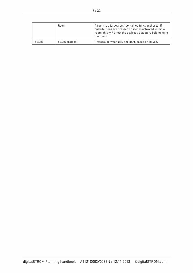
Room A room is a largely self-contained functional area. If push-buttons are pressed or scenes activated within a room, this will affect the devices / actuators belonging to the room.
dS485 dS485 protocol Protocol between dSS and dSM, based on RS485.

8 / 32
digitalSTROM Planning handbook A1121D003V003EN / 12.11.2013 ©digitalSTROM.com
2 distribution board The components of the digitalSTROM system
The new electricity can do more. With digitalSTROM, electrical devices can be connected and easily orchestrated through the existing power lines in your home. This retrofit-friendly invention makes energy management, creating a homely ambiance and security child’s play.
To enable the existing power lines of the electrical power circuits to be used for communication between the digitalSTROM Devices, different digitalSTROM components have to be installed in the distribution board.
This chapter describes the requirements to be observed for planning and the installation instructions for the installation of these components in the distribution board.
2.1 digitalSTROM filter (dSF)
The installation of digitalSTROM filters in the distribution board serves to condition the electrical grid to enable optimum communication between the components.
A maximum of three digitalSTROM filters (dSF) are required per distribution board (Fig. 1).
The whole length of the conductor of the connecting cables to the digitalSTROM filter (loop L-N) should not exceed 2 m.
If not all the outer conductors are equipped with a digitalSTROM meter, it is only necessary to provide a digitalSTROM filter for the outer conductors, which are connected to a digitalSTROM meter.
Fig. 1 Overview distribution board

9 / 32
digitalSTROM Planning handbook A1121D003V003EN / 12.11.2013 ©digitalSTROM.com
Input-side connection of the digitalSTROM filter
It is absolutely necessary that the digitalSTROM filter is connected on the input side of the digitalSTROM meter (Fig. 2).
Fig. 2 Input-side connection of the digitalSTROM filter
Operation on a three-phase system
The digitalSTROM filters can also be connected to an existing three-phase system, which supplies other consumers. However, this kind of connection is only suitable for the operation of a digitalSTROM system when the power supply is continuously available, i.e. when the power supply does not have to be temporarily interrupted, e.g. in order to switch other connected consumers on and off.
Fig. 3 Connection to a three-phase system

10 / 32
digitalSTROM Planning handbook A1121D003V003EN / 12.11.2013 ©digitalSTROM.com
Installation in a sub-distribution unit
To enable the use of the digitalSTROM system in a building with several sub-distribution units, (e.g. in a single-family residential building), digitalSTROM filters need to be installed in all sub-distribution units.
Distribution Components Comment
Second floor distribution
3 digitalSTROM filters (dSF)
6 digitalSTROM meters (dSM)
dS485 bus interconnection
The six digitalSTROM meters are equally distributed to L1 / L2 / L3. This is why three digitalSTROM filters are also required.
Bus terminating resistors are mandatory.
First floor distribution
2 digitalSTROM filters (dSF)
2 digitalSTROM meters (dSM)
dS485 bus interconnection to the 2nd
Since only two digitalSTROM meters are used (L1 / L3), only two digitalSTROM filters (L1 / L2) are necessary.
Ground floor distribution
1 digitalSTROM server (dSS)
3 digitalSTROM filters (dSF)
8 digitalSTROM meters (dSM)
dS485 bus interconnection to the 1st
Connecting the digitalSTROM server to the network line (LAN) to the router.
The digitalSTROM meters are equally distributed to L1 / L2 / L3. This is why three digitalSTROM filters are also required.
Bus terminating resistors are mandatory.
Main distribution Supply Single family residential building
- No installation of digitalSTROM components is necessary.
Fig. 4 Example of a sub-distribution unit istallation in a single-family residential building

11 / 32
digitalSTROM Planning handbook A1121D003V003EN / 12.11.2013 ©digitalSTROM.com
2.2 digitalSTROM meter (dSM)
General
The digitalSTROM meters (dSM), like the circuit breaker, are installed into the distribution board.
The digitalSTROM Meter ensures communication to the individual devices in the downstream power circuit. It also measures their performance.
The digitalSTROM system can be extended with additional circuits at any time. To this end, additional digitalSTROM meters are simply installed in the distribution board.
Within the installation, several digitalSTROM meters (a maximum of 62 units) communicate using a standardised protocol on a dS485 bus interconnection.
A digitalSTROM meter is capable of connecting a maximum of 128 digitalSTROM devices. Other, non-digitalSTROM-ready 230 V devices / consumers can still be used in the same power circuit. It must, however, be ensured that the maximum consumer current in the downstream power circuit does not exceed 16 amps.
If several digitalSTROM meters are installed, it is recommended to equally distribute them to all three outer conductors.
The maximum line length between the dgitalSTROM meter and the last digitalSTROM device is 50m.
Fig. 5 Maximum number of installed components
The digitalSTROM meters can only be operated with upstream digitalSTROM filters (dSF).
A digitalSTROM meter can (virtually) manage the downstream devices in up to 16 rooms. It is, however, recommended not to form more than four rooms per digitalSTROM meter. From the fifth room onwards, the response time in the rooms 5 - 16 increases by 250 ms.

12 / 32
digitalSTROM Planning handbook A1121D003V003EN / 12.11.2013 ©digitalSTROM.com
To allow sufficient convection between the devices (heat dissipation) observing minimum distances to other modules is recommended: With vertical installation it is recommended to maintain a minimum distance of 3 cm above and below the device, and a clearance of 0.5 TE after every third device (the digitalSTROM meter has a housing width of 1 TE). With horizontal installation a clearance of 0.5 TE should be provided after each digitalSTROM meter.
Fig. 6 Minimum distance
New building / complete refurbishment
It is recommended to provide one digitalSTROM meter for each room. /This way, all digitalSTROM Devices can log in automatically in the main room of the digitalSTROM Meter which is configured by default. This reduces the amount of work for configuring the system to a minimum.
Conversions
In the case of conversions, make sure not to create more than four rooms per digitalSTROM meter. If this is not possible, first create the much-used rooms, then the less-used rooms. This optimises accesses to the memory management of the digitalSTROM meter.
Apartment Basis Address
To prevent digitalSTROM devices from neighbouring digitalSTROM installations from interfering with each other (crosstalk), each installation is configured with a unique identifier (Apartment Basis Address).
The basis address, which is configured in the digitalSTROM server, determines the address of the digitalSTROM server and thus the increasing sequential numbering of the connected digitalSTROM meters.
The Apartment Basis Address which is valid for the digitalSTROM installation must be configured once in the web-based digitalSTROM Configurator on the digitalSTROM server. The numbering of the digitalSTROM Meters is then automatically transmitted to the connected digitalSTROM Meters.
The freely selectable address is between 0 ... 62. This allows a maximum of 62 digitalSTROM circuits (digitalSTROM meters) to be operated in a building.
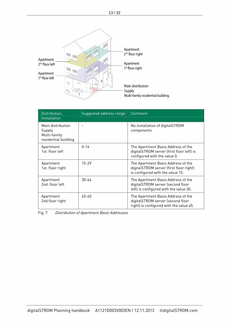
In a multi-family residential building with several independent digitalSTROM installations it is therefore especially important to ensure that the address ranges do not overlap (Fig. 7).
13 / 32
digitalSTROM Planning handbook A1121D003V003EN / 12.11.2013 ©digitalSTROM.com
Distribution, Installation
Suggested address range Comment
Main distribution Supply Multi-family residential building
- No installation of digitalSTROM components
Apartment 1st. floor left
0-14 The Apartment Basis Address of the digitalSTROM server (first floor left) is configured with the value 0.
Apartment 1st. floor right
15-29 The Apartment Basis Address of the digitalSTROM server (first floor right) is configured with the value 15.
Apartment 2nd. floor left
30-44 The Apartment Basis Address of the digitalSTROM server (second floor left) is configured with the value 30.
Apartment 2nd floor right
45-60 The Apartment Basis Address of the digitalSTROM server (second floor right) is configured with the value 45.
Fig. 7 Distribution of Apartment Basis Addresses

14 / 32
digitalSTROM Planning handbook A1121D003V003EN / 12.11.2013 ©digitalSTROM.com
2.3 digitalSTROM server (dSS)
The digitalSTROM server is optional for operating the digitalSTROM system.
The installation of a digitalSTROM servers enables connection to the Internet or a local network.
For a permanent connection to a local network or the Internet, LAN network cables must be provided in the distribution board. The connection can also be realised if necessary by means of power line connectors (PLC).
With the digitalSTROM server, installed devices and additional functions can be easily managed and configured via the web-based digitalSTROM Configurator. The web-based digitalSTROM Configurator can be easily opened in a web browser on any computer, without requiring additional software to be installed.
To enable the digitalSTROM installation to be operated via the digitalSTROM app on a smartphone, the digitalSTROM server must be permanently connected to a local network (local network connected to a wireless network). If the digitalSTROM server is connected to the Internet, it is also possible to access it via smartphone from outside the building. In this case, note that the setup of the local network router may have to be adapted.
In the web-based digitalSTROM Configurator it is also possible to install digitalSTROM server apps to enable, for example, the use of timer functions or for analysing the energy consumption in the individual circuits.
Thanks to the connection to the Internet, the digitalSTROM Server can access available firmware updates for digitalSTROM Server and digitalSTROM Meter and install them automatically after user confirmation.
The digitalSTROM server has a housing width of 1 HP.
The digitalSTROM server is powered by an external 24 V DC power supply. The power supply needs an output power of 10 W (including a supply for two USB devices on the digitalSTROM server, 0.5 A / 5 V per port).

15 / 32
digitalSTROM Planning handbook A1121D003V003EN / 12.11.2013 ©digitalSTROM.com
2.4 Bus interconnection dS485
The communication between the digitalSTROM meters and the digitalSTROM server takes place via a standardised dS485 bus interconnection.
The maximum line length of the bus interconnection between the bus devices is 100 m.
A terminating resistor of 120 Ω must be connected at both ends of the dS485 bus interconnection. The required terminating resistors are included in the product packaging of digitalSTROM meter and digitalSTROM server.
Fig. 8 Bus interconnection dS485
The bus topology of the dS485 bus interconnection must be arranged in a line.
The dS485 bus interconnection is capable of operating a maximum of 62 digitalSTROM meters. Several digitalSTROM servers cannot be operated on the same dS485 bus interconnection.
For the dS485 connection a paired cable with a corss section of 0.8 mm2 must be used (e. g. cable type G51 for installations in Switzerland, or cable type I-Y(ST)Y for installations in Germany).

16 / 32
digitalSTROM Planning handbook A1121D003V003EN / 12.11.2013 ©digitalSTROM.com
3 Planning This chapter describes basic information about digitalSTROM components and provides guidance to ensure the smooth and efficient planning of digitalSTROM installations.
3.1 Bases
The 3-part product designation allows the properties of the product to be quickly and easily recognised. Detailed information on the digitalSTROM products and their designations can be found in the digitalSTROM catalogue.
Fig. 9 Product designation
Here the example of the product designation GE-TKM210:
1. Part: GE (yellow) for the light application area
2. Part: TKM for the operation push button block
3. Part: 210 for push-button blocks with a dimmer output
3.1.1 digitalSTROM colour scheme
The application possibilities of digitalSTROM are very varied. To make orientation easier for the planners, electricians etc. and to make their work as uncomplicated as possible, the digitalSTROM devices are classified into different colour groups. Each colour group stands for a specific field of application.
This colour scheme is continued through to the housing colours of the digitalSTROM terminal blocks.
Fig. 10 digitalSTROM colour scheme

17 / 32
digitalSTROM Planning handbook A1121D003V003EN / 12.11.2013 ©digitalSTROM.com
Comments on Joker (black)
The Joker (black) area of application is a universal terminal block that allows digitalSTROM devices to be reconfigured to any other digitalSTROM colour (e.g. yellow for Light). To make full use of the many possibilities of the digitalSTROM colour concept (e.g. controlling all digitalSTROM devices with the same digitalSTROM colour via a digitalSTROM server app), the colour group should always be adapted to the use of the connected consumer. If a digitalSTROM device is configured for the Joker (black) are of application, the digitalSTROM device will only respond to higher-level activities. The Joker (black) area of application therefore also allows consumers to be integrated into a digitalSTROM system that cannot be covered with the available digitalSTROM colours, but which should respond to higher-level activities (typically devices that require a constant supply of electricity during operation, but that should be switched off when you are absent).
Note:
The SW-KL200 cannot be used to control any awnings, shutters or blinds.

18 / 32
digitalSTROM Planning handbook A1121D003V003EN / 12.11.2013 ©digitalSTROM.com
3.1.2 digitalSTROM components
Shape and size of components
This chapter describes the basic shapes / sizes / functions of the digitalSTROM components. The digitalSTROM components are each available in the different areas of application, such as Light (yellow) or Shade (grey).
3.1.2.1 digitalSTROM terminal block (KM)
The digitalSTROM terminal block is used for switching / dimming consumers and has a maximum switching or dimming capacity of 150 W / 105 VA (capacitive/trailing edge control).
The terminal block is not suitable for use with inductive loads.
The terminal block is suitable for installation in device boxes.
Fig. 11 digitalSTROM terminal block for Light

19 / 32
digitalSTROM Planning handbook A1121D003V003EN / 12.11.2013 ©digitalSTROM.com
3.1.2.2 digitalSTROM relais terminal block (KL)
The digitalSTROM relais terminal block is used as a relay actuator and has a maximum switching capacity of 1400 W / 700 VA (capacitive / inductive).
The terminal block is suitable for installation in device boxes.
Fig. 12 digitalSTROM relais terminal block

20 / 32
digitalSTROM Planning handbook A1121D003V003EN / 12.11.2013 ©digitalSTROM.com
3.1.2.3 digitalSTROM push button block (TKM)
The digitalSTROM push button block is used to connect a standard wall push-button as a control point. Depending on the digitalSTROM push button block, one, two, or four different wall push-buttons can be operated (1- way, 2- way, 4- way operation). The push buttonblocks with one capacity output can be configured in different modes (devcie push-button, area push-button or room push-button).
The terminal block is suitable for installation in device boxes.
Fig. 13 digitalSTROM push button block, universal

21 / 32
digitalSTROM Planning handbook A1121D003V003EN / 12.11.2013 ©digitalSTROM.com
3.1.2.4 digitalSTROM line switch (SDM)
The digitalSTROM cable dimmer is used for switching / dimming and has a maximum switching or dimming capacity of 150 W/105 VA (capacitive / trailing edge control).
The digitalSTROM line switch is suitable for use as a foot switch and is installed in the supply line of a consumer.
The digitalSTROM line switch is not suitable for use with inductive loads.
Fig. 14 digitalSTROM line switch

22 / 32
digitalSTROM Planning handbook A1121D003V003EN / 12.11.2013 ©digitalSTROM.com
3.1.2.5 digitalSTROM automation terminal blocks
The digitalSTROM automation terminal block is sued to monitor sensor signals.
The digitalSTROM automation terminal block, depending on the design, up to four sensor signals can be monitored and on the basis of status changes of the signals, control other digitalSTROM devices.
THE digitalSTROM automation terminal is used e. g. for movement, wind or rain sensors.
It is recommended, not to operate more than twenty automation terminal block inputs per digitalSTROM meter.
Fig. 15 digitalSTROM automation terminal block

23 / 32
digitalSTROM Planning handbook A1121D003V003EN / 12.11.2013 ©digitalSTROM.com
3.1.2.6 digitalSTROM inline adapter (ZWS)
The digitalSTROM inline adapter is used as a mobile relay switching contact and has a maximum switching capacity of 2300 W / 700 VA (capacitive / inductive).
The digitalSTROM inline adapter can be used in any socket outlet within the digitalSTROM installation and thus also temporarily for connected devices (e.g. Christmas lighting).
Fig. 16 digitalSTROM inline adapter ZW

24 / 32
digitalSTROM Planning handbook A1121D003V003EN / 12.11.2013 ©digitalSTROM.com
3.2 Room concept
A room is a largely self-contained functional area within a digitalSTROM installation. If push-buttons are pressed or scenes are activated within a room, this affects the digitalSTROM devices belonging to the room.
Plug & Play
In the factory setting of the digitalSTROM Meter, a room (main room) is preconfigured for the associated power circuit. All digitalSTROM components that are connected to the digitalSTROM meter are automatically assigned by default to this main room (Fig. 17).
New digitalSTROM components that are connected in this room (e.g. a floor standing lamp), are automatically assigned to the room and can be used without further configuration (Plug & Play).
Fig. 17 digitalSTROM meter main rooms

25 / 32
digitalSTROM Planning handbook A1121D003V003EN / 12.11.2013 ©digitalSTROM.com
Factory settings and room configurations
The example below shows the basic configuration of a digitalSTROM installation consisting of four digitalSTROM meters (Fig. 18).
Fig. 18 digitalSTROM meter basic configuration
The room concept offers simple and flexible configuration options that allow the functions of the digitalSTROM Devices to be used independently of the electrical power circuits.
The rooms are configured in the web-based digitalSTROM Configurator, the user interface of the digitalSTROM server. This tool allows you to create, merge or delete rooms. The room assignment of the individual digitalSTROM Devices in the power circuit can also be easily changed using the web-based digitalSTROM Configurator thanks to drag & drop.

26 / 32
digitalSTROM Planning handbook A1121D003V003EN / 12.11.2013 ©digitalSTROM.com
Dividing a power circuit into different rooms
If a power circuit (e.g. dSM 1 living room) contains several living areas such as “Living” or “Dining”, they can be represented by adjusting the basic configuration. This simply requires creating an additional room for „Living“ and renaming the main room as „Dining“ (Fig. 19). The digitalSTROM devices can then be assigned to the corresponding room according to their position in the installation.
Fig. 19 digitalSTROM meter with an additional room

27 / 32
digitalSTROM Planning handbook A1121D003V003EN / 12.11.2013 ©digitalSTROM.com
Merging devices from different power circuits in one room
If a living room (e.g. the office) consists of several power circuits for light and socket outlets (dSM3 + dSM4), the basic configuration divides this living room into two rooms (Fig. 17).
digitalSTROM now allows the two power circuits electrically separated by the installation to be merged again to form a logical room (Fig. 20).
Configuring such an inter-circuit room is very simple. You simply need to assign all digitalSTROM devices to one of the two rooms by drag & drop. It makes sense to rename this room accordingly afterwards. To enable continued use of Plug & Play, the empty room has to be deleted.
Fig. 20 Inter-circuit room
28 / 32
digitalSTROM Planning handbook A1121D003V003EN / 12.11.2013 ©digitalSTROM.com
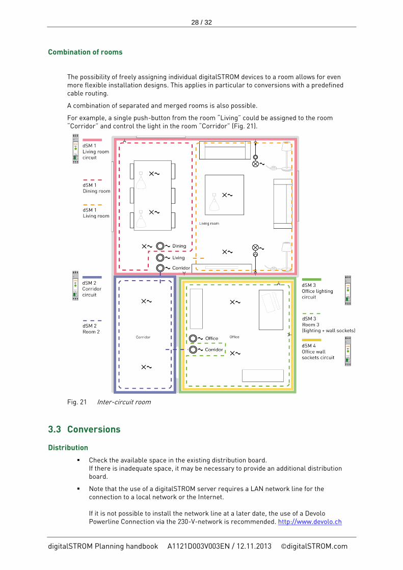
Combination of rooms
The possibility of freely assigning individual digitalSTROM devices to a room allows for even more flexible installation designs. This applies in particular to conversions with a predefined cable routing.
A combination of separated and merged rooms is also possible.
For example, a single push-button from the room “Living” could be assigned to the room “Corridor” and control the light in the room “Corridor” (Fig. 21).
Fig. 21 Inter-circuit room
3.3 Conversions
Distribution
Check the available space in the existing distribution board. If there is inadequate space, it may be necessary to provide an additional distribution board.
Note that the use of a digitalSTROM server requires a LAN network line for the connection to a local network or the Internet. If it is not possible to install the network line at a later date, the use of a Devolo Powerline Connection via the 230-V-network is recommended. http://www.devolo.ch

29 / 32
digitalSTROM Planning handbook A1121D003V003EN / 12.11.2013 ©digitalSTROM.com
The signal transmission via powerline does not interfere with the digitalSTROM system. Conversely, of course, neither does digitalSTROM interfere in any way with the powerline transmission.
The network connection can also be made via optical fibres. For this, the use of the system from Casacom is recommended. http://www.casacom.ch
In the case of conversions, make sure not to create more than four rooms per digitalSTROM meter. If this is not possible, first create the much-used rooms, then the less-used rooms. This optimises accesses to the memory management of the digitalSTROM meter.
Installation
The digitalSTROM products do not require any specific adjustments to the existing wiring / cabling outside of the distribution board. The devices are operated in the conventional 230 V AC network. Note, however, the recommendations for installation in the distribution board (convection) as well as the correct installation / wiring of the required digitalSTROM filters.
The existing light switches must be replaced with standard push buttons. To be able to operate shutters, awnings or blinds, corresponding push-buttons also have to be used.

30 / 32
digitalSTROM Planning handbook A1121D003V003EN / 12.11.2013 ©digitalSTROM.com
3.4 New buildings
Distribution
When planning new buildings, it is recommended to provide a separate digitalSTROM meter for each room.
If you merge several rooms on one power circuit in new buildings, make sure that , you do not plan more than four rooms per digitalSTROM Meter. If this is not possible, first create the much-used rooms, then the less-used rooms. This optimises accesses to the memory management of the digitalSTROM meter.
Plan a network connection to the distribution board if required.
Installation
Plan the installation with large sockets to ensure there is enough space for the installation of the digitalSTROM components and wiring.
Make a list of all the applications and devices requested by the end consumer. This will serve as a basis for determining the required digitalSTROM components, the related performance, the type of consumers (inductive, capacitive or ohmic).
For LED lights with external transformers, the use of the GE-KL200 terminal block is recommended due to the high start-up current.
Electronic transformers of LED / low-voltage lights should be charged with 80% of the nominal rating.

31 / 32
digitalSTROM Planning handbook A1121D003V003EN / 12.11.2013 ©digitalSTROM.com
4 Frequently asked questions Please visit the website http://www.aizo.com/support or the websites of the respective product manufacturers. There you can find useful support information and also a continuously updated list of Frequently Asked Questions (FAQ).

32 / 32
digitalSTROM Planning handbook A1121D003V003EN / 12.11.2013 ©digitalSTROM.com
5 Index
C Colour scheme ......................................................... 16
Comment on Joker .............................................. 17 Conversions.............................................................. 28
D digitalSTROM filter (dSF) ........................................... 8
Input-side connection ........................................... 9 Sub-distribution .................................................. 10 Three-phase system ............................................. 9
digitalSTROM inline adapter (ZWS) ......................... 23 digitalSTROM line switch (SDM) .............................. 21 digitalSTROM meter (dSM) ...................................... 11
Conversions ......................................................... 12 Minimum distances ............................................. 12 New building / complete refurbishment ............ 12
digitalSTROM push button block (TKM) .................. 20 digitalSTROM relais terminal block (KL) ................ 19 digitalSTROM server (dSS) ...................................... 14 digitalSTROM terminal block (KM) .......................... 18 Document ................................................................... 5
Requirements ........................................................ 5 Target group .......................................................... 5
dS485 bus interconnection ...................................... 15
F FAQ ........................................................................... 31
G Glossary...................................................................... 6
N New buildings .......................................................... 30
P Product designation ................................................. 16
S System ........................................................................ 8