digital railway joint development group outcome based ... · the interim joint development group...
TRANSCRIPT

Reference:157319NWRREPCPO000002
Issue/ver: 1.0
Date: 10/08/2018
Digital Railway – Joint Development Group
Outcome Based Project Delivery Strategy
Case Study: Moorgate – Northern City Line Renewal with ETCS Technology
Prepared By: Keith Attwood, Professional Head of Signalling, Alstom
Prepared By: Simon D’Cruz, Chief Engineer, Atkins .................................. Date: ......................... Prepared By: Ben Lane, Regional Commercial Manager, Siemens .................................. Date: ......................... Prepared By: Andrew Woods, Senior Systems Engineer, Siemens .................................. Date: ......................... Approved By: Christos Panou, Senior Project Engineer, on behalf of Daniel Holder, Programme Engineer Manager, Network Rail .................................. Date: ......................... Approved By: Graham Lawrence, Project Manager, Network Rail .................................. Date: .........................

2
Document Control
Electronic file reference: 157319NWRREPCPO000002
Disclaimer
Group Digital Railway has used its best endeavours to ensure that the content, layout and text of this document are accurate, complete and suitable for its stated purpose. It makes no warranties, expressed or implied, that compliance with the contents of this document will be sufficient to ensure safe systems of work or operation. Group Digital Railway will not be liable to pay compensation in respect of the content or subsequent use of this document for any purpose other than its stated purpose or for any purpose other than that for which it was prepared, except where it can be shown to have acted in bad faith or there has been wilful default.
© Copyright 2017 Group Digital Railway.
This document is the property of Group Digital Railway. It shall not be reproduced in whole or in part, nor disclosed to a third party, without the written permission of Group Digital Railway.
Document owner: Joint Development Group (JDG) – [email protected]
Distributed to: Public
Issue/Version: 1.0
Feedback to be provided to: Daniel Holder [email protected], Graham Lawrence: [email protected], and Joint Development Group (JDG) - [email protected]
Version Comments Updated By Reviewed By Date
0.5 Final Draft SDC 1st June 2018
0.6 JDG Preface included PW SDC 7th June 2018
0.7 Updated Exec Summary. Renamed System Integrator to RSIP. Updated RSIP/TI roles
SDC 8th June 2018
0.8 Updated report with B Lane’s comments.
BY 13th June 2018
0.9 Updated report with DR comments. BY BY, QZ, GL, DH 19th June 2018
0.10 Updated with Recommendations highlighted
SDC 6th July 2018
1.0 Final version for publication JDG Team 14th August 2018

3
Contents
EXECUTIVE SUMMARY ................................................................................. 6
1 INTRODUCTION ....................................................................................... 8
1.1 JOINT DEVELOPMENT GROUP (JDG) ..............................................................................................8
1.2 PROJECT BACKGROUND AND PROBLEM STATEMENT ..............................................................8
1.3 THE IJDG PROJECT TEAM ................................................................................................................9
1.4 KEY MILESTONES ........................................................................................................................... 10
1.5 EXPECTED OUTPUTS ..................................................................................................................... 10
1.6 FINDINGS .......................................................................................................................................... 11
2 OUTCOME SPECIFICATIONS ................................................................ 12
2.1 INTRODUCTION ............................................................................................................................... 12
2.2 THIN CLIENT ENGINEERING MODEL ............................................................................................ 13
2.3 DEFINING REQUIREMENTS ............................................................................................................ 14
2.4 THE V-LIFE CYCLE .......................................................................................................................... 15
2.5 SYSTEM OF SYSTEMS .................................................................................................................... 17
2.6 SAFETY MANAGEMENT ................................................................................................................. 18
2.7 VERIFICATION AND VALIDATION ................................................................................................. 19
2.8 GATEWAYS AND AUDITS ............................................................................................................... 19
2.9 CONFIGURATION CONTROL AND CHANGE MANAGEMENT ..................................................... 21
3 REQUIREMENT MANAGEMENT PROCESS AND TOOLS ................... 22
3.1 PROGRESSIVE ASSURANCE ......................................................................................................... 23
3.2 FOR TENDERING ............................................................................................................................. 23
3.3 FOR PLANNING ............................................................................................................................... 24
3.4 FOR PROJECT MONITORING AND CONTROL ............................................................................. 24
3.4.1 ENGINEERING MANAGEMENT STRUCTURE ....................................................................... 26
3.5 ENGINEERING INTERFACE MANAGEMENT ................................................................................. 26
3.6 SUPPLIER MATURITY ..................................................................................................................... 28
3.7 SECTION SUMMARY ....................................................................................................................... 28
3.8 ROLES, RESPONSIBILITIES AND ACCOUNTABILITIES ............................................................. 29
3.9 RAILWAY SYSTEMS INTEGRATION PARTNER (RSIP) ............................................................... 29
3.10 TECHNICAL INTEGRATOR ............................................................................................................. 32
3.11 SECTION SUMMARY ....................................................................................................................... 33
4 TECHNOLOGY SOLUTION .................................................................... 35

4
4.1 INTRODUCTION ............................................................................................................................... 35
4.2 INPUTS REQUIRED FOR ETCS DATA CREATION ....................................................................... 36
4.3 NRT .................................................................................................................................................... 37
5 FORM OF CONTRACT ........................................................................... 39
5.1 PROPOSED FORM OF CONTRACT ............................................................................................... 39
5.2 CONTRACT CLAUSES .................................................................................................................... 39
5.2.1 GENERAL .................................................................................................................................. 39
5.2.2 CONTRACTOR’S MAIN RESPONSIBILITIES .......................................................................... 40
5.2.3 TIME .......................................................................................................................................... 40
5.2.4 QUALITY MANAGEMENT ......................................................................................................... 40
5.2.5 PAYMENT .................................................................................................................................. 41
5.2.6 COMPENSATION EVENTS ...................................................................................................... 41
5.2.7 USE OF EQUIPMENT, PLANT AND MATERIALS ................................................................... 41
5.2.8 LIABILITIES AND INSURANCE ................................................................................................ 41
5.2.9 TERMINATION .......................................................................................................................... 41
5.2.10 OPTION CLAUSES ................................................................................................................... 41
5.3 COST COMPONENTS ...................................................................................................................... 42
5.4 NEC4 VS NR12 TERMS AND PROPOSED ADDITIONAL TERMS ................................................ 42
5.5 SUPPLIERS APPROACH TO CONTRACT RISK ............................................................................ 43
6 MAINTENANCE CONTRACTING ........................................................... 44
6.1 BACKGROUND ................................................................................................................................ 44
6.2 MANAGING CHANGE ...................................................................................................................... 44
6.3 MAINTENANCE SCOPE ................................................................................................................... 44
6.4 SPARES AND REPAIRS .................................................................................................................. 45
6.5 CONSIDERATIONS FOR THE SPARES SCOPE ............................................................................ 45
6.6 TECHNICAL SUPPORT .................................................................................................................... 46
6.7 TECHNICAL INVESTIGATION ......................................................................................................... 46
6.8 TESTING EQUIPMENT, SPECIAL TOOLS AND TRAINING EQUIPMENT .................................... 46
6.9 MANAGING OBSOLESCENCE........................................................................................................ 46
6.10 NETWORK AND CYBER SECURITY MANAGEMENT ................................................................... 47
6.11 KEY PERFORMANCE INDICATORS ............................................................................................... 47
6.12 RELIABILITY TARGETS AND PERFORMANCE ............................................................................ 47
6.13 MAINTENANCE REPORTING .......................................................................................................... 47
6.14 TENDER FORMAT ............................................................................................................................ 48
7 RISKS AND CHALLENGES .................................................................... 50

5
7.1 CULTURAL CHANGES .................................................................................................................... 50
7.2 SYSTEM OF SYSTEMS .................................................................................................................... 50
7.3 SYSTEMS AUTHORITY .................................................................................................................... 50
7.4 TECHNICAL CHANGES REQUIRED ............................................................................................... 51
8 CASE STUDY: MOORGATE – NORTHERN CITY LINE RENEWAL ...... 52
8.1 BACKGROUND ................................................................................................................................ 52
8.2 CONOPS ........................................................................................................................................... 52
8.3 CLIENT DELIVERY TEAM ................................................................................................................ 53
8.4 ENGINEERING STRUCTURE .......................................................................................................... 54
APPENDIX 1 ................................................................................................. 56
6
EXECUTIVE SUMMARY
The Interim Joint Development Group (IJDG) Moorgate Project Team has analysed the problem statement to
determine whether using an Outcome Based Specification approach can facilitate a different project delivery
model. The IJDG Project Team used the proposed Moorgate: Northern City Line Renewal as a case study for
the deployment.
To realise the Digital Railway vision requires the complex integration of technology, processes and people and
focus needs to be given equally to each to ensure success. The need for the delivery team to manage across
the business (i.e. train operators, maintainers, TOCs, etc.) as well as manage the technology supplier requires
a different approach.
The key issues include:
• Digital Rail technology requires integration between the technology and the people and process that is
significantly greater than for traditional railways.
• Introduction of new technology means that there is a shift in knowledge base to the suppliers and their
products.
• Over specifying complex integrated solutions would restrict the supplier’s ability to apply products and
to innovate.
• A systematic rather than a prescriptive approach to project delivery is required.
Outcome Based Specifications enables focus on what is important to the success of the project which can be
lost during the project lifecycle. The requirements set should be as well defined as possible to allow innovation.
However, the constraints within the contract must also be carefully considered. With the supplier taking on more
responsibility, they must be cognisant of being able to demonstrate that the requirements have been met in a
complex regulatory environment.
The IJDG Project Team supports a new thin client organisation that is responsible for the system integration
with the System of Systems and the stakeholders. Responsibility for technical integration will be transferred to
the supplier.
During the transition there will be significant risk resulting from managing new technology deployment within a
new organisation structure. New processes will need to be introduced which would require practical application
rather than strict adherence. Resistance to change can also be expected.
A review of the technical issues arising from the deployment of ETCS is considered in the report including the
need to have accurate site data and the interface with NRT who will be required to provide GSM-R technology
to the project.
The NEC4 contract is considered to be an appropriate vehicle for the new delivery strategy and with the
recommended amendments can be used to manage the risks of the new structure whilst providing incentives
to the suppliers in key areas. This includes arrangements for the long-term management of the system.
The Moorgate Northern City Line ETCS Renewal is a good opportunity to assess the performance of a new
contracting model. The project is over a small geographic location but includes the complexity of an integrated
solution including ETCS trackside and onboard as well as a transition point and tunnel operations.

7
The Panel recommends that for Moorgate, an Outcome Based Specification (OBS) is considered with a suitable
project delivery team model. Several recommendations made in this report should be considered for further
assessment to enable this strategy to be successful.
Key Recommendations
Recommendation Document Reference
OBS is a suitable project delivery model for the Moorgate Northern City Line Project
Section 8
NEC4 Contract with amendments is a suitable vehicle for contracting OBS Section 5
Progressive Assurance with Audits and Gateways to be deployed for Moorgate Section 3.1
Business Change Management Team for initial projects Section 7.1
New Job Titles in the new organisation to enable cultural change Section 7.1
Physical Railway Configuration Data needs to be improved Section 7.4
NRT collaboration with the Technical Integrator (TI) Section 7.4
8
1 Introduction
1.1 Joint Development Group (JDG)
Building on the lessons learned from the previous Early Contractor Involvement (ECI) work streams combined with an industry specific benchmarking exercise, the Digital Railway Programme (DRP) developed the concept of a Joint Development Group (JDG). The JDG seeks to leverage the breadth and depth of technical competencies that exist in the supply chain to inform a diverse industry opinion and respond to novel and ambiguous problem statements that emerge within the Digital Railway Programme. The core concept behind the JDG is to bring together a community of suppliers with a wide range of skills and capabilities, each able to be called upon/invited to support the DRP’s development activities. This new way of working allows the DRP to utilise the diversity of thinking from the supply chain on a variety of problem statements. For the remainder of CP5, the JDG will be in its interim phase (IJDG) during which the concept and operating model will be validated prior to a solution being locked in CP6.
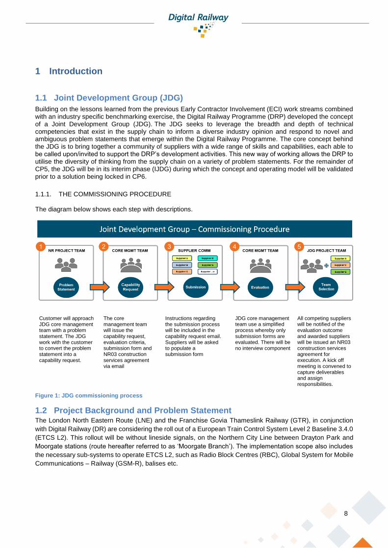
1.1.1. THE COMMISSIONING PROCEDURE
The diagram below shows each step with descriptions.
Figure 1: JDG commissioning process
1.2 Project Background and Problem Statement The London North Eastern Route (LNE) and the Franchise Govia Thameslink Railway (GTR), in conjunction
with Digital Railway (DR) are considering the roll out of a European Train Control System Level 2 Baseline 3.4.0
(ETCS L2). This rollout will be without lineside signals, on the Northern City Line between Drayton Park and
Moorgate stations (route hereafter referred to as ‘Moorgate Branch’). The implementation scope also includes
the necessary sub-systems to operate ETCS L2, such as Radio Block Centres (RBC), Global System for Mobile
Communications – Railway (GSM-R), balises etc.
Customer will approach JDG core management team with a problem statement. The JDG work with the customer to convert the problem statement into a capability request.
The core management team will issue the capability request, evaluation criteria, submission form and NR03 construction services agreement via email
Instructions regarding the submission process will be included in the capability request email. Suppliers will be asked to populate a submission form
JDG core management team use a simplified process whereby only submission forms are evaluated. There will be no interview component
All competing suppliers will be notified of the evaluation outcome and awarded suppliers will be issued an NR03 construction services agreement for execution. A kick off meeting is convened to capture deliverables and assign responsibilities.

9
Through this commissioned piece of work DR wants to continue exploring the ‘thin client’ approach, whereby
the DR organisation itself operates leanly, relying on its partners and suppliers for delivery support. One way of
achieving this is through Outcome Specification based procurement, and more specifically, Outcome
Specifications when developing a future Invitation To Tender for the Moorgate Branch ETCS L2 rollout
described above.
Based on collective experience of suppliers and the information to be delivered, working on this project, DR had
the aim of understand what procedures suppliers envisage may need to change within, to support an Outcome
Specification document. This includes identification of inputs and level of data quality required along with a
methodology for change, to create a robust suite of Outcome Specification documents for the Moorgate Branch.
This suite of documents will support the LNE/GTR/DR plan to roll out ETCS Level 2 across the East Coast Main
Line.
1.3 The IJDG Project Team The IJDG Project Team working on the Moorgate problem statement included Subject Matter Experts from
around the industry, working collaboratively alongside the Digital Railway Programme customer to develop a
solution. The Moorgate organogram and key are below.
Figure 2: Organisation
Digital Rail Team
Supplier Community Team
Core Management Team Graham Lawrence
Project Manager
Ben Lane
Regional Commercial Manager, Siemens
Andrew Woods
Senior Systems Engineer, Siemens
Simon D’Cruz
Chief Engineer, Atkins
Keith Atwood
Professional Head of Signalling, Alstom
Dan Holder
Problem Statement Owner, Programme Engineer Manager
Pareisse Wilson
Project Manager, IJDG
Bernard Yeo
Project Engineer
Christos Panou
Senior Project Engineer

10
1.4 Key milestones
Figure 3: Key Milestones
1.5 Expected outputs The original brief included 9 expected outputs.
No Expected Output Output 1 What would an Outcome Specification look like and how should
this be presented in the tendering process for a DR Scheme of
this size?
The Outcome Specification is described in two key documents – the Concept of Operations and the Application High Level Specification (CRD). In Section 2, there is a description of how the Outcome Specifications will be managed through the V-Lifecycle. Specific consideration of the Moorgate project is given in Section 8.
2 How would current DR Practices and processes need to change?
.
The Engineering Practice and process would need to change to reflect the new contracting arrangements. Section 3 considers the implication of these changes
3 Given the shift to Outcome Specifications based procurement, how are the roles of DR and a Supplier impacted? Do new roles need to be defined? If so, what does this look like?
Sections 2 and 3 consider the implications on the roles of those involved in the development of these technologies. Newly defined roles of Railway Systems Integration Partner (RSIP) and Technical Integrator help to define the new responsibilities of the Client and Supplier and try to set out their respective involvements in the deployment process. Section 7 considers the risks and challenges of this new arrangement.
4 What is the role of DR and the Supplier in the delivery of outcomes and what would the assurance regime be?
Section 2 proposes a new regime of gateways and audits to replace the current assurance model.
5 Define the roles of System Integrator and Technical Integrator, how do they inform a deployment strategy given the shift to
Outcome Specifications based procurement?
Section 3 describes the roles of the RSIP and the Technical Integrator.
23 April, Kick Off Meeting
4 May, identified areas of expertise
for Problem Statement
22 May, finalisedoutcomes
8 June, final report submitted

11
No Expected Output Output 6 What are the asset and data requirements for a scheme this
size? What need to be included as part of the above?
The implication for the asset and the data requirements are considered in Section 4. Specific issues for the Moorgate Project are considered in the Case Study
7 How could performance be measured and compensated?
Section 2 considers potential methods of measuring the Supplier which could be developed into a payment structure
8 A view to whether the existing asset data need the quality
requirements of an Outcome Specification based procurement?
In Section 4 there is a description of the quality of data requirements for ETCS systems and how this can be applied to an Outcome Based Specification
9 What lessons learnt from previous tenders can be shared with DR?
The team has drawn from its experience and knowledge of other technology deployments to build this strategy for a thin client organisation using Outcome Based Specifications
1.6 Findings The JDG report concentrated on four key areas:
• How to develop and use Outcome Based Specifications through the project lifecycle
• The impact on the current engineering practices and the roles and responsibilities of the engineers
• The impact on the engineering specifically around the handling of data and the technical interface with
others
• The commercial and contractual implications of using Outcome Based Specifications
The Moorgate Northern City Line project has been considered as a case study and the specific findings have
been addressed separately.

12
2 Outcome Specifications
2.1 Introduction
In the Digital Railway, the stakeholders are predominantly the same as they are for conventional projects. There
will still be physical infrastructure; track, traction power, signalling, control centres, stations, passenger
information systems, performance monitoring/recording systems, all using a backbone communication network.
These systems will still need the supporting organisational structures for the day to day running of the railway
infrastructure operations department, Railway undertakings (TOC, FOC), Rolling Stock Operating Company
(ROSCO), infrastructure maintainer, rolling stock maintainer, route controllers, rostering clerks, timetabling
clerks. The conventional railway system allows each of these organisational structures to focus inwards towards
their own elements of physical infrastructure and procedures. The railway system operating as multiple discrete
sub systems, many of which have minimal interactions with the other sub systems around them, managed
through compliance with historically proven standards. Where sub systems are ‘connected’ information is
generally transferred as an information dump at predefined intervals to allow the other sub systems to extract
what they require and discard the rest. These interactions with others are out of necessity and generally for the
personal gain of the individual organisation. So, for example a train operator will liaise closely with a route
controller to recover their train pattern following perturbation because it minimises their customer (passenger)
discontent and places their rolling stock and train crews into the required locations to minimise onward delays
caused by rostering issues such as rest periods, competency, route knowledge, train maintenance schedules
etc. Whilst the route controller’s interests are to minimise financial penalties associated with attributable delays.
In the Digital Railway the core disciplines to control the railway will remain the same; the change will be upon
how these disciplines interact. The core sub systems being used to perform the day to day utilising available
and new technology will require a higher level of integration into the railway system.
This integration at the digital level will aid the railway in meeting the demands of the current and future population
demographic who have become reliant upon technology to provide anything and everything they ask. In the
railway system of systems this translates into the vital and non-vital systems required to operate the railway of
the future. But even here the boundaries will change, what is vital? The train control sub systems that ensure
the safe movement of trains (interlocking) or the traffic management sub system that plans train movements to
minimise conflicts at junctions and maintains a smooth throughput to meet the timetable?
In simplistic terms the needs of the railway users can be met by identifying the required functions and assigning
to the appropriate subsystem. The digital information transfer between these subsystems becoming critical for
day to day operations also creates a necessity for clear definitions as to what is required. As these system
interfaces become more complex and reliant upon on each other, the raw standard compliance approach
becomes untenable. The System of Systems must therefore be represented as explicit requirements,
characterised and assigned to sub systems and / or interfaces. The traditional engineering structure applied to
project delivery following standards compliance approach fails to meet the future needs and the engineering
structure and roles need to be manipulated in the system of systems.
Requirements Management are the activities that ensure requirements are identified, documented, maintained,
communicated and traced throughout the life cycle of a system, product, or service.

13
The result of requirements engineering is a hierarchy of requirements that:
• enables an agreed understanding between stakeholders (e.g., acquirers, users, customers, operators,
suppliers)
• is validated against real-world needs,
• can be implemented provides a basis of verifying designs and accepting solutions
For a contracting strategy, that is based on Outcome Based Specifications where the responsibility for the
detailed design relies on the supplier to assure their works there is a need for a requirements management
driven strategy.
Furthermore, the client team can also focus on assuring the outcomes of the project are satisfied and
demonstrating those outcomes to the client and the stakeholders. This change in focus removes them from
obligation of checking the suppliers’ works as they are assured that works is being satisfied through the reporting
generated by the requirements management systems.
A robust requirements management system that is integrated into the project delivery, technical assurance and
reporting systems should provide the degree of satisfaction required to assure clients, stakeholders and
designers alike that the right products are being delivered.
2.2 Thin Client Engineering Model
The traditional supplier project delivery assurance model as depicted in
Figure 4 predominantly focuses effort towards the supplier. Engineering assurance is achieved at project level
through the client organisation conducting detailed analysis of design deliverables required by the supplier to
construct and verify the build status of the end solution. The acceptance reviews are based on confirming
compliance with standards and procedures, clients’ needs being considered satisfied if the installed end product
is compliant.
Figure 4: Current NR Signalling Engineering Model
In the Digital Rail environment, the system interactions will only provide the required benefits if they are clearly
defined. To be clearly defined they must first be identified and captured. With clearly defined and measurable
system performance criteria and interactions, engineering assurance of suppliers can be tailored to utilise
different and more appropriate assessment techniques. The aim being to assure the delivery of the end solution
is progressing to plan and meets all achievable stakeholder requirements.

14
The Digital Railway engineering model therefore needs to place greater emphasis on identifying and engaging
with stakeholders to understand their needs and interactions, enabling them to be translated into clearly defined
requirements that can be developed into technical solutions. This in turn will allow for the transition from the
standards compliance engineering assurance process, to an outcome-based assurance technique. This
engineering management model requires greater effort in the direction of the stakeholder and relatively less
effort in the direction of the supplier, creating the ‘thin client’ model depicted within Figure 5.
Figure 5: Future Engineering ‘Thin Client’ Model
The ‘thin client’ model follows the consideration that the client’s effort would be better placed in managing the
higher-level interfaces and stakeholders to ensure that expectations are managed, and outcomes achieved
through ensuring whole system integration or System of Systems integration. The client therefore takes on the
role of ‘Railway System Integrator Partner (RSIP)’.
2.3 Defining Requirements The Digital Railway programme will affect the entire industry and there are several different stakeholders that
will be impacted by the new technology; each one
will have their expectations and perceived
overcomes. It is almost evitable that, whilst they
might all share the same overall ambitions for the
Programme, their specific needs may well be
contradictory or overambitious.
The Application Business Requirements (ABR)
will be developed to consolidate all the
stakeholder’s needs into a single common set.
Potential stakeholders in the ABR could include
DfT, RDG/FOCs, Supply Chain, TfL, RSSB, etc.
as depicted in Figure 6. The ABR describes the
outcomes that will be met by any given
programme or project.
The ABR can be generated using several different sources including; Client /Sponsor Brief, regulatory
requirements, stakeholder engagement workshops, standards, etc.
It is inevitable that the form of the input will come in different formats; maybe narrative, or, standards,
diagrammatic or a specific set of outcomes. These will be interpreted into the Concept of Operations (ConOps)
and the Application High-Level Outcomes (CRD). These documents transform the stakeholder requirements
into the application specific operational, functional and non-functional requirements. Once this process is
underway it will be necessary to conduct a series of workshops with the various users to ensure that the system
is being developed with their needs in hand.
ABRDfT
Trade unions
RDG/ RFG
Supply Chain
TfLRSSB
Maintainer
Operator
ORR
Figure 6: Stakeholders input into the ABR
RSIPStakeholder Supplier
EffortEffort
15
The requirements will also include for any assumptions or constraints that are ascertained as a part of the
stakeholder engagement processes.
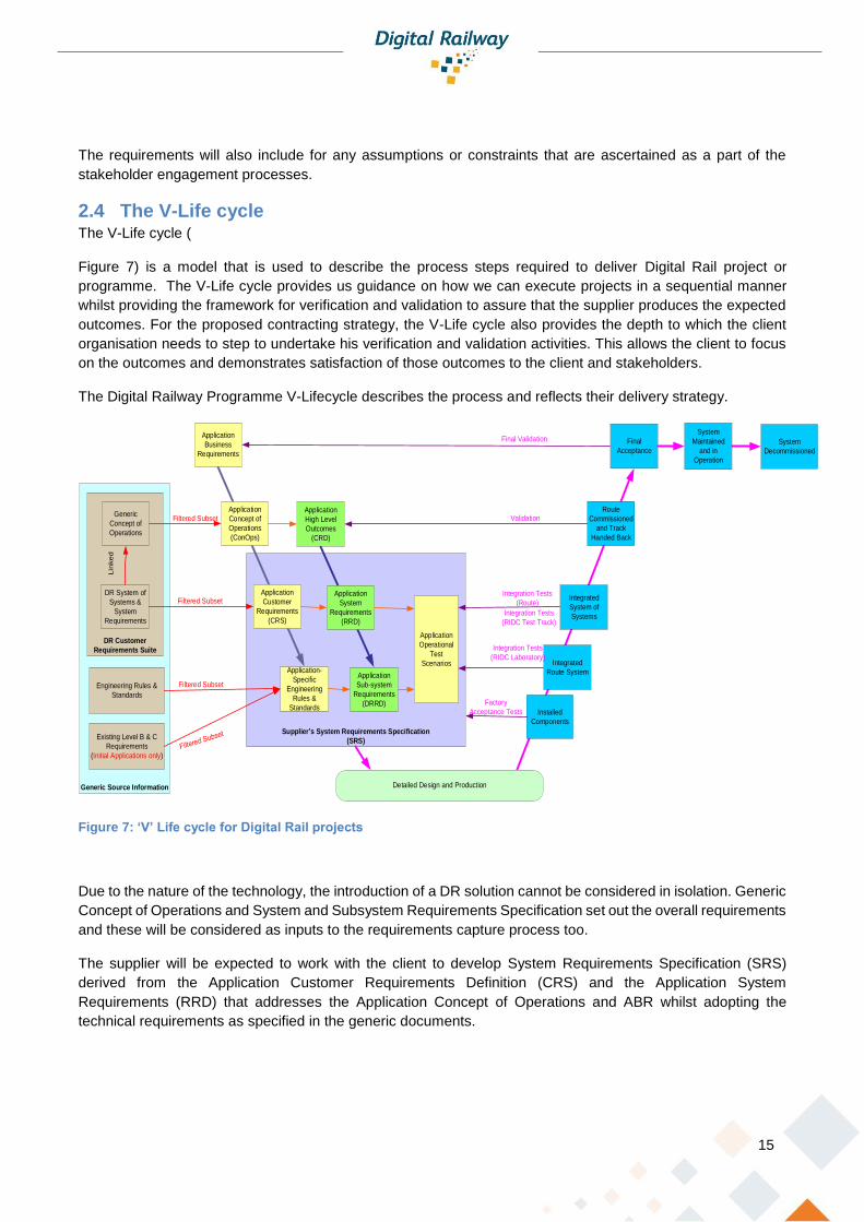
2.4 The V-Life cycle The V-Life cycle (
Figure 7) is a model that is used to describe the process steps required to deliver Digital Rail project or
programme. The V-Life cycle provides us guidance on how we can execute projects in a sequential manner
whilst providing the framework for verification and validation to assure that the supplier produces the expected
outcomes. For the proposed contracting strategy, the V-Life cycle also provides the depth to which the client
organisation needs to step to undertake his verification and validation activities. This allows the client to focus
on the outcomes and demonstrates satisfaction of those outcomes to the client and stakeholders.
The Digital Railway Programme V-Lifecycle describes the process and reflects their delivery strategy.
Supplier s System Requirements Specification
(SRS)
Generic Source Information
DR Customer
Requirements Suite
Application
Concept of
Operations
(ConOps)
Application
Customer
Requirements
(CRS)
Application-
Specific
Engineering
Rules &
Standards
Route
Commissioned
and Track
Handed Back
Integrated
Route System
Installed
Components
Detailed Design and Production
Factory
Acceptance Tests
Integrated
System of
Systems
Application
Business
Requirements
Generic
Concept of
Operations
DR System of
Systems &
System
Requirements
Engineering Rules &
Standards
Final
Acceptance
Lin
ked
Compliance
Integration Tests
(RIDC Laboratory)
Integration Tests
(RIDC Test Track)
Integration Tests
(Route)
System
Maintained
and in
Operation
System
Decommissioned
Filtered Subset
Existing Level B & C
Requirements
(Initial Applications only)
Validation
Final Validation
Application
High Level
Outcomes
(CRD)
Application
System
Requirements
(RRD)
Application
Sub-system
Requirements
(DRRD)
Filtered Subset
Filtered Subset
Application
Operational
Test
Scenarios
Figure 7: ‘V’ Life cycle for Digital Rail projects
Due to the nature of the technology, the introduction of a DR solution cannot be considered in isolation. Generic
Concept of Operations and System and Subsystem Requirements Specification set out the overall requirements
and these will be considered as inputs to the requirements capture process too.
The supplier will be expected to work with the client to develop System Requirements Specification (SRS)
derived from the Application Customer Requirements Definition (CRS) and the Application System
Requirements (RRD) that addresses the Application Concept of Operations and ABR whilst adopting the
technical requirements as specified in the generic documents.
16
This allows for tailored solutions to be realised that are based on the specific project demands, the supplier’s
technology and the contracting strategy. The requirements for these solutions are captured and the variances
to the Generic are understood and managed under configuration control processes. This allows the Network
Rail team to;
• implement the best solution for the given application,
• understand where projects have varied from the generic, and,
• adopt best practice from projects and improve the generic.
To ensure that the overall DR solution can be integrated as a “System of Systems”, it will be essential to ensure
that the mandatory or common integration requirements are well defined and controlled to ensure that different
projects can be interoperable.
Assurance has traditionally been undertaken by continual design checking, reviews and approvals. However,
this is more difficult to do where the technology and the tools that develop the technology are automated and
software based. Furthermore, Digital Rail technology is a fast-developing forum where solutions are complex
and integrated in data. The solutions are driven by the supplier’s technology and that is where the expertise
resides.
It is, therefore, natural for the quality assurance to revert to the supply chain as they retain the expertise and
knowledge of their products. The client still needs to assure themselves of the solution, but need to look at
different approaches.
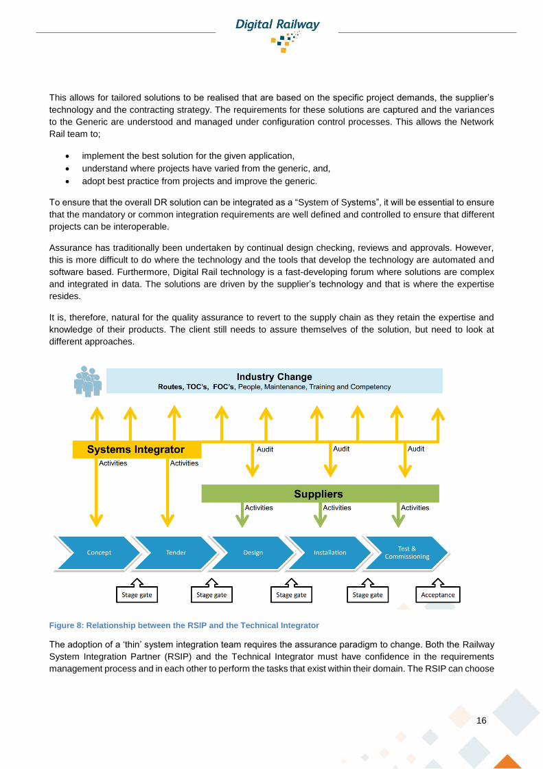
Figure 8: Relationship between the RSIP and the Technical Integrator
The adoption of a ‘thin’ system integration team requires the assurance paradigm to change. Both the Railway
System Integration Partner (RSIP) and the Technical Integrator must have confidence in the requirements
management process and in each other to perform the tasks that exist within their domain. The RSIP can choose

17
to check certain key deliverables to ensure the quality of the outputs are assured. The level and depth of
checking should be set out at the beginning of the arrangement, but be assessed on a periodic basis (i.e. at the
gateways) to determine if the right level of surveillance is suitable. However, the Technical Integrator will retain
the primary responsibility for the design process. The use of audits to assess the overall quality of the outputs
can be conducted to retain the ability to assess the work being undertaken at the bottom of the ‘V’, but these
audits should be focussed on enabling the project to proceed rather than a mechanism to ‘check-up’ on the
detail.
During the detailed design and development stages, the supplier will be expected to demonstrate that they are
conducting verification and validation exercises to the client. The client team will not be actively involved in these
processes.
The RSIP can use several techniques during the project to assure themselves, including verification tests that
can be conducted at each stage – i.e. do all the parent requirements have child requirements? Are there
orphaned requirements? Has the parent been reasonably defined?
The requirements management tool provides the ability to connect parent requirements to children
requirements. It is reasonable to assume that the relationship between a parent and their children is a one to
many one.
2.5 System of Systems The development of application specific solutions will need to be carefully managed to ensure interoperability
with other DR projects. The generic specifications provide both the architecture and the requirements needed
to ensure the various projects can be effectively integrated into the System of Systems (SoS).
Some of the objectives of the DR SoS generic design are to:
• Successfully deploy an integrated and repeatable train command, control and safety system on GB rail
network including
o Traffic Management System;
o Connected-Driver Advisory System;
o ETCS Trackside, incorporating equipment trackside for Level 2 (no signals), modern interlocking
technologies, and trackside equipment necessary for fitted trains running elsewhere on the GB rail
network
o ETCS Onboard
• Provide the framework to ensure that all DR delivery activities are aligned against a common understanding
and baseline architecture (i.e. maintenance, operations, engineering, people and process etc.);
• Provide a foundation for enabling the systems to be configured;
• Automated control of train paths derived from a planned time-table, and
• Increased service reliability and the potential for increased capacity and performance (subject to the
specifics of the deployment)

18
Business Systems
IXLSCWS
Central (STW)
SCWS Portable
(STW)
Trackside Objects
TM
GSM-R Data
FTN(X) EULYNX
SCADA
DRACAS
Digital Railway Programme
TM Protection (Portable)
CA
Trackside objects include level crossing control, train detection, lineside signals where fitted, remote monitoring, TPWS, trackside train monitoring systems etc.
Business systems include operational and business
systems e.g. TRUST, TOPS, Stock & Crew, TD Data etc.
Voice comms includes GSM-R
Voice system and lineside telephony
CCTV
Onboard systems
Voice Comms
CTI
Infrastructure and Onboard
Data Hub#
Trackside Maintainer
Onboard Maintainer
Trackside Operator
Onboard Operator
KMC
TM CCTV inputs include for level crossings, tail lamp
detection, sidings capacityETCS
TracksideETCS
Onboard
COMPASS Central
COMPASS Trackside
COMPASS Onboard
C-DAS Trackside
IM
C-DAS Onboard
C-DAS Trackside
RU
ATOOnboard
LINX
ATOTrackside
Figure 9: System Architecture
Figure 9 is the system architecture for the digital technology solution and demonstrates how the systems will be
integrated to ensure interoperability of systems.
As each project develops their Customer Requirements Definitions that are based on the Generic Requirements
and then tailored to the specific application, careful consideration needs to be given to preserve the generic
requirements such that the interoperability and integration of the project solution into the wider System of
Systems can be achieved.
This is a major challenge and should not be underestimated.
The need to meet challenging project delivery programmes will require the RSIP to make decisions on how to
achieve certain generic requirements that might not be aligned with the System of Systems approach. For
transformational programmes where the end state is not fully defined or understood the risk of deviation in
requirements is potentially high without careful management. This issue is further complicated by parallel
deployments of the Digital Rail solution all “learning” how to apply the requirements to their solution. Lessons
learned and good practice will need to be shared across the industry to ensure that the System of Systems is
realised.
2.6 Safety Management The hazard records that are generated from the safety assurance process are key deliverables for any project.
It is important to be able to demonstrate the Control Measures that need to be applied to satisfy the safety

19
argument for the project was proven. The control measures can be considered as emerging requirements and
should be considered equal to any input requirements.
If the control measures are to be considered as
requirements, and, therefore subject to
attention, in our management process then the
source, the hazard log, could also be considered
as part of the requirements management
process. A robust Requirements Management
Tool can allow for the management of the
hazard log too. Traditionally the hazard log is
maintained in an excel spreadsheet which is
quite restrictive. By considering the Hazard Log
as an element of a database, the hazard data
becomes more usable.
Like the process for requirements capture, the
CRS can consider the control measures from
two sources; the applicable items from the generic
hazard log and the application hazard log. The hazards and the control measures can be decomposed into the
CRS and attributed so that they are marked as Safety Requirements. This effectively builds the Safety
Requirements Specification within the CRS document.
This process embeds the safety assurance work within the requirements management process. The control
measures will be treated the same as all requirements and follow the V-Life cycle process being traced through
the detailed design, implementation and testing regimes. The Application Operational Test Scenario will be
prepared to include tests that demonstrate the safety requirements so that team can witness and be assured
that these are satisfied.
2.7 Verification and Validation Requirements management provides a technique of tracing requirements through the life of the project. This
provides the ability to verify that the children requirements are satisfying their parents. The verification activity
requires expert attention to ensure that the requirements are being satisfied correctly. This is especially
important where the requirements are complex with one to many relationships.
Where the traceability is being undertaken by the suppliers, the client organisation is reliant on their work being
undertaken correctly. The client organisation needs the supplier to assure that the requirements are being
satisfied during the detailed design and development phase.
2.8 Gateways and Audits There will be a need to ensure that the project is progressing according to plan and that the requirements are
being well defined and assured in the design and development phases. The use of audits and gateway controls
are the best approach.
Audits will be used to assure the requirements process is being conducted in an appropriate manner. The audit
should be seen as an opportunity to evaluate the evidence within the requirements database. The objective will
be to demonstrate that the supplier is developing the solution correctly. Where deficiencies may be found the
audit team and the supplier will agree corrective actions that can be enabled as part of the next phase of works.
Applicaton Hazard Control
Measures
Generic Control
Measures
Safety Requirements
Figure 10: Managing control measures as requirements
20
Audits will be conducted during the lower part of the ‘V’ Lifecycle where the supplier is wholly responsible for
the process.
Gateways shall be conducted at key points in the project where the client needs to ensure that the technology
is being deployed correctly, i.e. critically when the systems are being brought in to trial service or into operation.
Gateways will be used by the supplier to demonstrate to the client and stakeholders that the solution meets the
requirements. To ensure that these Gateways operate in a pragmatic and progressive way, the prioritisation of
requirements needs to be made at an early stage in the project. The Gateways will be led by Gateway Managers
whose role will be to focus on the key requirements that affect that gateway.
The client needs to be assured that the supplier has completed the works and that is satisfactory to pass to the
next phase of the project subject to agreement on action/mitigation plans that need to be implemented to
address any open issues that are identified.
Gateways are conducted to ensure the project is sufficiently developed / mature to move to the next delivery
phase. The gate process should commence during the initial phases of the project development through to final
handover and closeout. Early gates should be used to identify the gate stages applicable to a project and identify
the key deliverables and maturity level of the deliverable required at each phase to ensure the project risks and
expectations are managed. The gateway review should be conducted by a person independent of the direct
delivery of project but with sufficient understanding and knowledge of the project to ensure potential issues are
identified. The independent person should also be empowered to agree targets and mitigations against any
deficiencies identified during the gate review process.
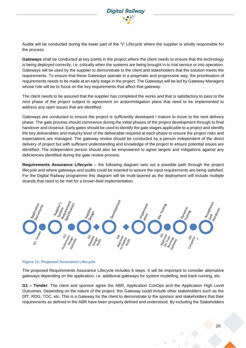
Requirements Assurance Lifecycle – the following diagram sets out a possible path through the project
lifecycle and where gateways and audits could be inserted to assure the input requirements are being satisfied.
For the Digital Railway programme this diagram will be multi-layered as the deployment will include multiple
strands that need to be met for a brown-field implementation.
Figure 11: Proposed Assurance Lifecycle
The proposed Requirements Assurance Lifecycle includes 6 steps. It will be important to consider alternative
gateways depending on the application, i.e. additional gateways for system modelling, test track running, etc.
G1 – Tender: The client and sponsor agree the ABR, Application ConOps and the Application High Level
Outcomes. Depending on the nature of the project, this Gateway could include other stakeholders such as the
DfT, RDG, TOC, etc. This is a Gateway for the client to demonstrate to the sponsor and stakeholders that their
requirements as defined in the ABR have been properly defined and understood. By including the Stakeholders

21
in this stage, we are ensuring their engagement with the high-level requirements. This is a Go/No-Go Gateway
that happens before the supplier is engaged.
G2 – Preliminary Design Gateway: with the finalisation of the supplier’s System Requirements Specification,
the client and supplier agree the exact requirements to be implemented by the project. It is also possible to
finalise other project matters, i.e. programmes, costs, etc. The Gateway is undertaken with the supplier and is
for the supplier to demonstrate that the requirements have been properly defined and understood. This Go/No-
Go Gateway allows the supplier to progress into the Design and Development phase.
G3 (s) – Supplier Design Audit (s): this is an audit of the progress being made during the detailed design and
development phase. The number and frequency of audits will depend on several factors, i.e. the duration of the
design and development phase, the sensitivity of the project and the maturity of the supplier.
G4 (s) – Pre-Deployment Audit (s): This audit is an overview of the solution prior to the system being
manufactured or installed on site. The number and frequency of audits will depend on several factors, i.e. the
duration of the design and development phase, the sensitivity of the project and the maturity of the supplier.
G5 – Approval for Train Running: This is a key Gateway where the supplier will demonstrate their system is
ready for dynamic train running. The supplier will need to demonstrate that the verification and validation of
requirements has been met including the client’s relevant testing requirements as defined in the Application
Operational Test Scenarios. This is a Go/No-Go Gateway that empowers the supplier to undertake dynamic
test running.
G6 – Completion: This is a key Gateway where the supplier will demonstrate that all the requirements have
been satisfied including all the requirements in the Application Operational Test Scenarios. This is a Go/No-Go
Gateway that allows for the final handover of the system. It should be noted that this will happen after the
operational handover which will be achieved by the normal handover/handback processes.
2.9 Configuration Control and Change Management Audits and Gateways also provide an opportunity to baseline the requirements. Baselining the requirements at
key points in the project enable multi-disciplined activities to work from a source of the truth with confidence that
they are working from the same condition. It also provides the client a baseline for reference.
Projects mature across time and new emerging requirements are to be expected and managed. New
requirements may come from the design and development process, from the safety assurance process and
other sources including change of stakeholder expectations.
Using requirements management to assess changes provides a systematic approach that can provide a holistic
view of how the change impacts the entire system. The change can be analysed by tracing both up and down
the requirements path and across the affected areas to ensure that the impact of the change is fully understood
before it is implemented. Both the client and the stakeholder can have an agreed understanding of the impact
through this process.
As changes emerge throughout the project life it is important to re-consolidate the changes – this can be done
at the next baseline.

22
3 Requirement Management Process and Tools This proposal is based on integrating a solution that acknowledges the current working practice with tools that
have been used on mega projects to deliver a progressive assurance process that enables project owners to
take a holistic and pragmatic stance in the management of complex railway programmes.
The processes and tools described below have been successfully deployed on multiple overseas projects where
the client has a “thin organisation” which have relied upon using outcome-based specifications and minimal
national standards.
The ability to integrate the Requirements Management Database with the Electronic Document Management
System and the Progressive Assurance Tool is extremely powerful
Requirements Management Database: Traditionally in the UK, the DOORS database has been the “go to”
application for managing requirements. The database is a collation of requirements that can be linked together
to demonstrate that the design, implementation, verification and validation are aligned.
For complex and multi-layered projects, the need to understand how
requirements are being interpreted as the design matures through the
project lifecycle is both challenging and complicated. It is also essential
to understand to ensure the outputs realise the intended outcomes.
However, technical submissions remain a document driven process
meaning the Requirements Management is subservient to the
demands of a programme driven document submittal register.
Documentation that is not coordinated with the Requirements
Management database can contain many orphaned and unrealised
requirements.
Electronic Document Management Systems: Projects, invariably, are driven by documents. These
documents are registered in an Electronic Document Management System such as Enterprise Bridge (eB). This
system provides an electronic record of the deliverables, their versions and their history. However, these
documents tend to be isolated without practical links with other documents. Embedded requirements in these
documents can be lost, mis-acquired or deviate the results incorrectly.
Progressive Assurance Tool: The Progressive Assurance provides the ability to manage the requirements
assurance process. It can be used to capture assurance checking comments on the decomposition of
requirements and on documents. It provides clear traceability paths both upwards and downwards. Reporting
can be managed better, providing stakeholders clarity on their specific requirements, as well as providing project
delivery teams focus on the issues.
The combination of the three systems (system suppliers can provide more than one product within their system)
provides a framework for requirements to managed in a proactive and controlled manner.
By having a model that connects the three systems together we can ensure that the requirements in the
documentation are aligned with the requirements in the database. Changes in the documents or in the database
can be flagged in the progressive assurance tool for attendance and assessment. This approach provides the
ability to manage the configuration in a dynamic and proactive manner.
Using a web-based requirements management system provides suppliers (and their supply chains) the ability
to use the “live” database to undertake their requirements management activities. The client can observe the
Requirements Database
Progressive Assurance Tool
Document Control
Figure 12: RM Tool arrangement

23
progress remotely without the need for intrusive design review and checking regimes. There is still a need for
audits to be conducted but these can be planned at key stages in the project timeline.
3.1 Progressive Assurance As the ABR is outcome based it will be benefit driven in terms that can relate to the
various stakeholders. Using progressive assurance techniques, it is possible to take
the stakeholders on the same journey with full visibility of how their benefits are being
translated into design requirements through to delivered products.
By using the input documents as a baseline, the supplier shall develop the System
Requirement Specifications and then trace the relationship with the performance requirements. The relationship
can be one to one or one to many depending on the nature of the requirements.
By using a progressive assurance technique, the client can then monitor the development of the design and the
evolution of the client requirements in real time online. The client can be satisfied that the design of their
requirements is maturing through the design process without undertaking intrusive and time-consuming review
processes. Gateways can be established (as set out above) throughout the design process that checks the
maturity of the requirements rather than on the completion of design documents
Progressive Assurance has been proven to provide the client the ability to monitor the supplier’s work by
measuring compliance to the requirements rather than on the ability to submit documents. Focus can be given
to requirements that are not evolving allowing the client and supplier to trouble shoot better.
By giving the supplier the freedom to operate in the design domain it can improve the client-supplier relationship.
Governance becomes more than a simple measure of compliance adherence and thus removing some of the
unnecessary and irrelevant constraints that a compliance approach introduces.
3.2 For Tendering Traditionally tendering has been a process of reviewing tender submissions that
are provided in paper or electronic format. Even having a compliance matrix can
be difficult to follow or trace the requirements and therefore be assured that the
supplier has demonstrated that can achieve the requirements.
With a Requirements Management Tool (RMT), the system can be used as the
key tendering submission. The client organisation will prepare the tendering
specification requirements within a subset of the database which is issued to the
tendering parties.
The tenderers are then required to respond using the database demonstrating
how they will comply with the tender requirements.
The tender review panel then use the progressive assurance tool to evaluate the
tenderers responses, confirm compliance, comment and, where necessary,
raise Technical Queries.
Tender Queries can be issued in the database formatted format and responses can be received in the same
manner.
In this way, the tendering process can be well managed, configuration control can be maintained, and progress
can be easily demonstrated.
Tender Specification
Tender Response
Tender Review
Tender Queries
Figure 13: Tendering process managed by the RMT

24
3.3 For Planning Every requirement must be analysed to determine its prioritisation, its lifecycle and its verification and validation
(test) conditions.
The process of requirements analysis also provides a method of planning the requirements life.
Requirement prioritisation is the process of assessing the need; most projects consider whether the
requirement is mandatory (i.e. safety/operation critical), preferred, or optional. Prioritisation allows the delivery
teams to focus on the key requirements to ensure that the project can be successfully handed over to operations.
This is important on complex projects where there are 10s of thousands of requirements to be analysed, traced
and assured.
Every requirement has its
own timeline. That is to
mean that requirements
can be assured at different
times in a project lifecycle.
Predominately,
requirements tend to be
validated during the
testing phase, but some
could be assured in the
design phase,
manufacture or the
installation.
Overall, we can generate
a Requirements Lifecycle
Model that describes the
completion of all the requirements. This model describes when the requirements are completed and does not
reflect the actual effort conducted in the requirements management exercise. It is therefore sensible, to weight
effort for all the requirements (i.e. weighting for requirements could be based on the current DR model design
of 50%, 95% and then at completion of the testing).
We can now monitor the project using two ‘S’ Curves; Requirements Lifecycle Model and Requirement Effort
Model in mapping requirements. The first provides a measure of the progress to actual completion and the
second provides a measure of the value of the work undertaken.
These requirements management techniques provides another tool to the project in planning the works being
undertaken.
3.4 For Project Monitoring and Control Progressive Assurance is designed to enable the engineers in both the client and supplier’s organisation to
focus on the system engineering solution. The system provides the tools for tracing the requirements through
the project life cycle. It also provides the ability to review and comment in a controlled place.
Design Reviews: Projects will continue to deliver requirements in document formats for the foreseeable future.
These documents can be uploaded into the progressive assurance tool and compared to the requirements
management database. Compliance can be assessed and where comments required they are generated within
Manufacture/Install
System Test
Dynamic TestDesign
Progress %
Effort weighted progress S Curve
Requirement Lifecycle
Completion
Project Lifecycle
Figure 14: Requirements driven 'S' Curves

25
the tool. Reviews are therefore linked to requirements and are contained with the Progressive Assurance Tool
providing a permanent and traceable record of the assurance process.
A requirements traceability record can be a particularly powerful tool when demonstrating the safety assurance
process to others such as the ISA or the regulator.
New versions of the documents can be reviewed in the same system and updates that have resulted from
review can be assessed in the system.
Progress: using requirements management to monitor the progress can be a useful project management tool
that can be used alongside the more traditional progress matrices. The ‘S’ Curves are just some of the reports
that a progressive assurance tool can generate. As the system is “live” it can provide daily, weekly or monthly
reports that can be optimised for the audience, i.e. stakeholder specific progress reports that focuses on the
specific stakeholder and their needs.
Benefits Driven Programmes: with technology projects there is an opportunity to manage the delivery
programme based on delivering benefits rather than delivering products. By understanding what functionality
provides what benefits we can judge what value can be had from providing them early. This type of programme
strategy can only be considered in specific projects such as traffic management systems where the functionality
can be achieved in a more staged manner rather than ETCS where the requirements requires all products to
be realised at the same time.
Managing Innovation: Digital Rail takes advantage of new and emerging technology to deliver solutions. The
delivery strategy needs to be open to the continued innovation in new technology to ensure the most appropriate
solutions are realised.
Managing requirements progressively allows the delivery team to “innovate” by defining those requirements that
are mandatory and those that can be innovated. Programmes can then be developed so that the innovation
requirements follow different timelines to the mandatory ones. Separating mandatory and innovative
requirements means the delivery of the core functionality can be focussed on and assured to achieve the
schedule whilst allowing the design teams more time to innovate and create solutions that meet the emerging
requirements.
26
3.4.1 Engineering Management Structure
The Digital Railway introduces a need for greater interaction between track and train. To realise the railway
system benefits required for the future, these systems need to be highly integrated.
The current Network Rail signalling project delivery structure focuses heavily upon re-assessing the finite detail
of the supplier’s deliverables, in particular the application design. The complexity of the system interfaces using
software and application data makes this traditional approval process (design/check/review/approve) ineffective
in assuring the sponsor that the high-level safety, functional and operating requirements are being fulfilled.
The engineering assurance model required for corporate governance must therefore change to ensure that
suppliers are providing a solution that meets the client’s needs. This model will need to apply different
techniques to provide this assurance with focus on moving towards measuring the supplier through
outcomes/outputs rather than through the constraints of standard compliance. The modified assurance model
will create a different engineering management structure focusing on the interactions between the project and
other stakeholders. This model is being referred to as the ‘Thin Client’.
3.5 Engineering Interface Management
The thin client model presents a single supplier interface to the client. In practice this model would be extremely
limiting and contrary to the client procurement policy. The key elements of the Digital Railway (TMS, ETCS
Trackside, ETCS Onboard, Communication network) may be procured from multiple suppliers. This creates a
further consideration as to how the engineering interactions between multiple suppliers can be managed. The
solution must ensure that the technical skills within each supplier organisation work effectively together to
achieve the final integrated Digital solution.
Network Rail’s Engineering Management for Projects process (NR/L2/INI/02009 Issue 6) provides three
engineering interface management structure models (options 1-3). The three models are based around the
responsibility for design integration. Recent IP signalling renewals projects have applied a hub and spoke
contracting model with Network Rail managing the interfaces and acting as the design integrator, this is
represented as option 2 within the standard.
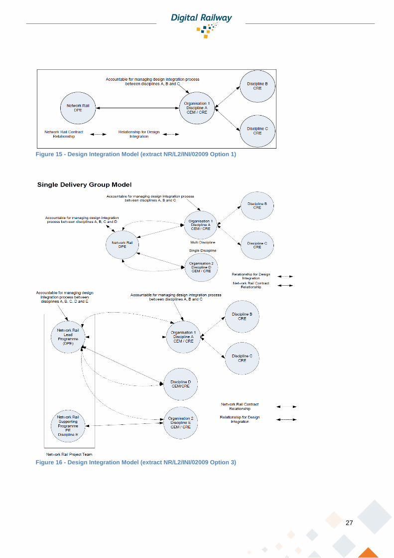
Option 1 [Figure 15] and Option 3 [Figure 16] align with the ‘thin client’ approach where the supplier Contractors
Engineering Manager (CEM) takes responsibility for the integration of the multi discipline designs. The two
options allow for different contracting arrangements, with option 1 covering the single source option whereby
the supplier is contracted to undertake all discipline activities, while option 2 permits Network Rail to contract
individual disciplines directly but appoints one supplier as the design integrator. Using the existing management
models within the thin client structure the traditional CEM role will be a ‘Technical Integrator’ for the activities
within their work scope. The Technical Integrator (supplier) will become responsible for conducting assurance
activities in line with their Quality Management System, allowing the RSIP to satisfy themselves that assurance
is being actively controlled/managed by receipt of supplier declarations and reports.
27
Figure 15 - Design Integration Model (extract NR/L2/INI/02009 Option 1)
Figure 16 - Design Integration Model (extract NR/L2/INI/02009 Option 3)
28
3.6 Supplier Maturity
The supplier maturity will dictate how closely Network Rail will need to monitor and interface with the supplier
in the discharge of their duties for corporate governance, legislation and regulation compliance. The engineering
model applied needs to ensure that Network Rail is executing its duty to adequately manage safety and business
risk.
A justifiable method to support Network Rail’s decision to discharge some of these duties to the supplier under
the thin client model could be based on a predetermined supplier maturity level scoring or ranking. The ranking
system could be based on external body supplier qualification schemes such as Railway Industry Supplier
Qualification Scheme (RISQS) and Capability Maturity Model Integration (CMMI). Network Rail would use this
pre-assessed ranking to supplement a maturity level verification process at tender pre-qualification or during
the formal tendering process. This will allow Network Rail to execute an appropriate level of control, scaling its
engineering delivery team commensurate with the risk, complexity and novelty, as appropriate and forming part
of Network Rails Assurance process for level 2 – Corporate Oversight.
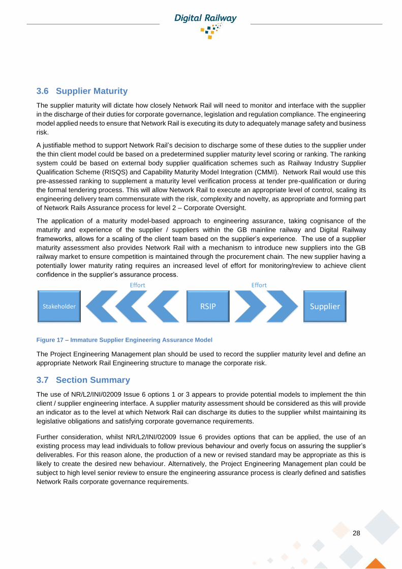
The application of a maturity model-based approach to engineering assurance, taking cognisance of the
maturity and experience of the supplier / suppliers within the GB mainline railway and Digital Railway
frameworks, allows for a scaling of the client team based on the supplier’s experience. The use of a supplier
maturity assessment also provides Network Rail with a mechanism to introduce new suppliers into the GB
railway market to ensure competition is maintained through the procurement chain. The new supplier having a
potentially lower maturity rating requires an increased level of effort for monitoring/review to achieve client
confidence in the supplier’s assurance process.
Figure 17 – Immature Supplier Engineering Assurance Model
The Project Engineering Management plan should be used to record the supplier maturity level and define an
appropriate Network Rail Engineering structure to manage the corporate risk.
3.7 Section Summary
The use of NR/L2/INI/02009 Issue 6 options 1 or 3 appears to provide potential models to implement the thin
client / supplier engineering interface. A supplier maturity assessment should be considered as this will provide
an indicator as to the level at which Network Rail can discharge its duties to the supplier whilst maintaining its
legislative obligations and satisfying corporate governance requirements.
Further consideration, whilst NR/L2/INI/02009 Issue 6 provides options that can be applied, the use of an
existing process may lead individuals to follow previous behaviour and overly focus on assuring the supplier’s
deliverables. For this reason alone, the production of a new or revised standard may be appropriate as this is
likely to create the desired new behaviour. Alternatively, the Project Engineering Management plan could be
subject to high level senior review to ensure the engineering assurance process is clearly defined and satisfies
Network Rails corporate governance requirements.
RSIPStakeholder Supplier
EffortEffort

29
3.8 Roles, Responsibilities and Accountabilities
The Digital Railway thin client engineering management structure will evolve around two key defined roles:
➢ Railway System Integration Partner (RSIP)
➢ Technical Integrator
These roles will take the lead in ensuring the technical solution fulfils the requirements for the system of systems,
meeting the safety and functional requirements. They will also retain responsibility for executing engineering
assurance activities to comply with legislation and corporate governance.
3.9 Railway Systems Integration Partner (RSIP)
The RSIP will be a role within the refined engineering structure with a focus on the greater railway system
(System of Systems). Responsible for ensuring the technical requirements of stakeholders are clearly defined,
captured and satisfied. The specific duties of the RSIP will align with the contracting model and supplier maturity
to ensure that Network Rail’s duties and obligations as required by legislation and governance polices are
adequately executed. However, the RSIP’s focus will be on ensuring that stakeholder interfaces are defined
and managed to ensure whole system
integration.
The stakeholder interactions and interface to
the sponsor shall be detailed within the
project engineering management plan.
The RSIP may need to execute some or all
of the duties of the DPE role as defined
within NR/L2/INI/02009, where these have
not been discharged to the Technical
Integrator. This shall be detailed within the
Project Engineering Management plan.
The RSIP should contain a Lead Engineering competence and be appointed.
The RSIPs key technical duties could include:
➢ Act on behalf of DRs Systems Authority as the system authority for the System of Systems
o Owner of project engineering management plan
o Define the NR engineering structure based on the maturity of the supplier & baseline solution.
o Act as registration entity - updating of each European Union Member State’s National Vehicle
Register (NVR)
o European Railway Agency (ERA) project register (one stop shop)
Figure 18 –RSIP’s Interactions
Stakeholder
System
Integrator
Independent
Assessor
Regulatory
Body
Route
Sponsor
Technical
Integrator
(Supplier)
Others
Railway
Undertaking
30
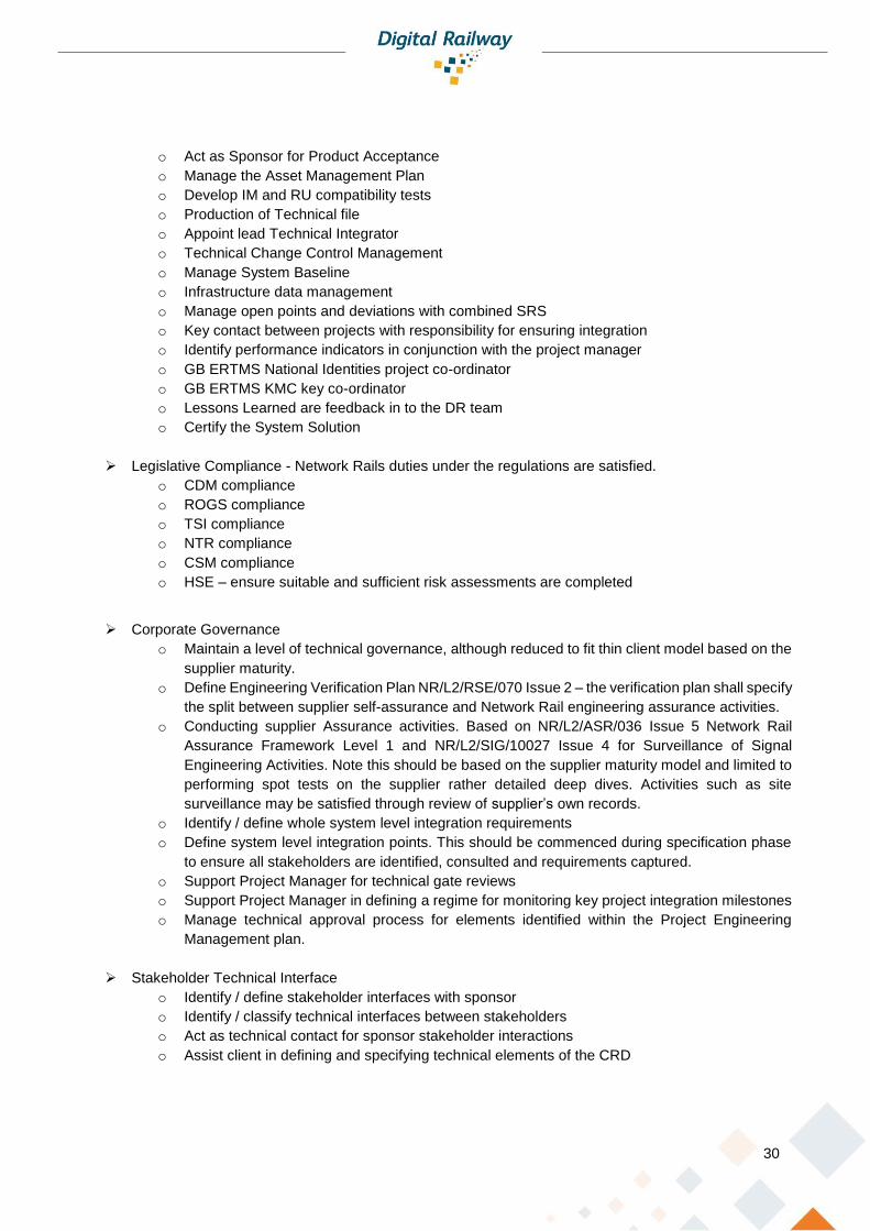
o Act as Sponsor for Product Acceptance
o Manage the Asset Management Plan
o Develop IM and RU compatibility tests
o Production of Technical file
o Appoint lead Technical Integrator
o Technical Change Control Management
o Manage System Baseline
o Infrastructure data management
o Manage open points and deviations with combined SRS
o Key contact between projects with responsibility for ensuring integration
o Identify performance indicators in conjunction with the project manager
o GB ERTMS National Identities project co-ordinator
o GB ERTMS KMC key co-ordinator
o Lessons Learned are feedback in to the DR team
o Certify the System Solution
➢ Legislative Compliance - Network Rails duties under the regulations are satisfied.
o CDM compliance
o ROGS compliance
o TSI compliance
o NTR compliance
o CSM compliance
o HSE – ensure suitable and sufficient risk assessments are completed
➢ Corporate Governance
o Maintain a level of technical governance, although reduced to fit thin client model based on the
supplier maturity.
o Define Engineering Verification Plan NR/L2/RSE/070 Issue 2 – the verification plan shall specify
the split between supplier self-assurance and Network Rail engineering assurance activities.
o Conducting supplier Assurance activities. Based on NR/L2/ASR/036 Issue 5 Network Rail
Assurance Framework Level 1 and NR/L2/SIG/10027 Issue 4 for Surveillance of Signal
Engineering Activities. Note this should be based on the supplier maturity model and limited to
performing spot tests on the supplier rather detailed deep dives. Activities such as site
surveillance may be satisfied through review of supplier’s own records.
o Identify / define whole system level integration requirements
o Define system level integration points. This should be commenced during specification phase
to ensure all stakeholders are identified, consulted and requirements captured.
o Support Project Manager for technical gate reviews
o Support Project Manager in defining a regime for monitoring key project integration milestones
o Manage technical approval process for elements identified within the Project Engineering
Management plan.
➢ Stakeholder Technical Interface
o Identify / define stakeholder interfaces with sponsor
o Identify / classify technical interfaces between stakeholders
o Act as technical contact for sponsor stakeholder interactions
o Assist client in defining and specifying technical elements of the CRD

31
o Ensure stakeholders are advised of/aware of training requirements
➢ Tender Support
o Current pre-contract award DPE duties as defined in NR/L2/INI/02009 Issue 6 will need to be
retained by the RSIP
o Endorse contract technical work scope
➢ Requirements Capture / Management
o Manage requirements outside of the supplier’s remit.
o Selection and gap analysis of Generic source information (concept of operations, System of
systems requirements, Engineering rules & Standards)
o Prepare relevant technical requirements for inclusion in contract
o Capture stakeholder requirements and ensure clearly defined (Customer Requirements
Specification)
o Assist in production of RRD
o Compile DRRD
o Identify and define expected supplier outcomes and measurement criteria from combined SRS
o Align stakeholder CRS with Digital Railway RS and Route RS
➢ Change Control
o Manage changes to stakeholder requirements
o Facilitate the resolution of issues within the defined requirements, deviations and non-
compliances with the requirements.
➢ Safety Assurance
o Appoint Safety Assessor
o Agree safety assurance process and CSM models to be applied.
o Accept Safety-Related Application Conditions (SRACs) exported by supplier
o NoBo / DeBo interface
o Confirm that adequate assurance has been undertaken to take the system into use.
➢ Pre-supplier appointment
o Act as Technical Integrator
➢ Project RSIP Handover to Route Asset Manager (RAM)
o Transfer system performance requirements to RAM
o Verify outcome criteria satisfied / identify deviations
o Lesson learned outputs
o Authorisation to operate
o Warranty
The need for a Maintenance RSIP to manage the maintenance contract has not been considered in this
remit, but it may be of consideration in the future.
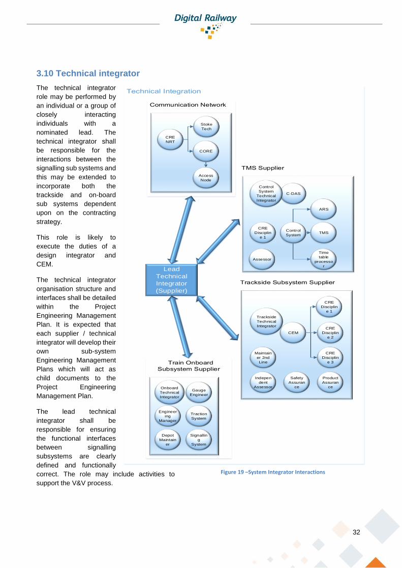
32
3.10 Technical integrator
The technical integrator
role may be performed by
an individual or a group of
closely interacting
individuals with a
nominated lead. The
technical integrator shall
be responsible for the
interactions between the
signalling sub systems and
this may be extended to
incorporate both the
trackside and on-board
sub systems dependent
upon on the contracting
strategy.
This role is likely to
execute the duties of a
design integrator and
CEM.
The technical integrator
organisation structure and
interfaces shall be detailed
within the Project
Engineering Management
Plan. It is expected that
each supplier / technical
integrator will develop their
own sub-system
Engineering Management
Plans which will act as
child documents to the
Project Engineering
Management Plan.
The lead technical
integrator shall be
responsible for ensuring
the functional interfaces
between signalling
subsystems are clearly
defined and functionally
correct. The role may include activities to
support the V&V process.
Figure 19 –System Integrator Interactions
Lead
Technical
Integrator
(Supplier)
CEM
CRE
Disciplin
e 1
CRE
Disciplin
e 2
CRE
Disciplin
e 3
Engineer
ing
Manager
CRE
Disciplin
e 1
CRE
NRT
Stoke
Tech
CORE
Control
System
ARS
TMS
Time
table
processo
r
C-DAS
Access
Node
Gauge
Engineer
Traction
System
Signallin
g
System
Depot
Maintain
er
Safety
Assuran
ce
Indepen
dent
Assessor
Product
Assuran
ce
Trackside
Technical
Integrator
Onboard
Technical
Integrator
Control
System
Technical
Integrator
Assessor
Maintain
er 2nd
Line

33
The Technical Integrator shall be nominated by the lead supplier and appointed by the RSIP.
Technical Integrator key responsibilities:
➢ Principal Contractor
➢ Subsystem Interface Act as subsystem design authority
➢ Subsystem integration
o Act as CEM including managing the self-assurance of all technical documents. The CEM, under
the NEC4 contract, would need to satisfy the Service Manager that the correct approvals have
been obtained to enter the system into service.
o Identify functional interfaces between physical sub systems i.e. CCS trackside, On board,
Control system / TMS and communication network.
o Ensure functional interface requirements are clearly defined and allocated to the relevant sub-
system
o Ensure sub system interfaces are subject to configuration management as required by the
engineering management plan.
o Lead Interdisciplinary checks and reviews (IDC/IDR) ensuring functional interface designs are
aligned, integrated and meet the defined requirements.
o Ensure tests are defined for testable functional interface requirements
➢ Ensure open points within sub systems / interfaces are managed
➢ Competence
o Appoint competent people to key roles identified within the Technical Integrators organisation
structure.
o Ensure key personnel within the technical integrator framework are formally appointed.
➢ Manage technical change.
➢ Put forward product acceptance
➢ Compile SRS
➢ Audit / surveillance checks
➢ Technical KPI reporting in line with supplier QMS
➢ Technical Query Management between Technical Integrators
➢ Technical Query escalation to RSIP
➢ Generating Engineering Compliance Certificate
➢ Manage and resolve construction issues
➢ Manage handover process to maintainer
➢ Define sub system training programmes
Further consideration will need to be given to defining these roles so that the contractual boundaries and
responsibilities are well understood. Contractual consideration needs to be given to the delegation of duties by
each party and how the technical authority can execute his works whilst engaging with suppliers that they may
have no contractual relationship with (i.e. train manufacturers). This has not been considered in this remit.
3.11 Section Summary
The RSIP and Technical Integrator will be the leading responsible engineers within the thin client model. The
RSIP role being held by the client organisation, whilst the Technical Integrator role is contained within the
supplier organisation. The detail of the responsibilities split will be based upon the level of devolution for
engineering assurance from the client to the supplier, which should reflect the maturity of the supplier within the
GB mainline railway environment. The project engineering management plan should be used as the vehicle to

34
define and record the engineering management structure applied to the project, thus ensuring that the detail of
the roles and boundaries are clearly recorded.

35
4 Technology solution
4.1 Introduction The use of ETCS Level 2 effectively mandates a specific solution architecture for the signalling system. An
ETCS level 2 system will consist of an Interlocking Safety Processor which is in close communication with the
Radio Block Centre. The Radio Block Centre generates Movement Authorities which are based upon the
geography of the railway and the availability of routes from the Interlocking. The Interlocking communicates to
the trackside assets (points machines and train detection) via the communication network (FTN) and the RBC
communicates to the ETCS onboard units via the fixed communications network (FTN) and the radio network
(GSM-R). This is shown in Figure 20.
.
ETCS OnboardETCS Onboard
InterlockingRadio Block
Centre
Control Centre
Trackside Assets
ETCS Onboard
Units
FTN/GSMR
Trackside Assets
Trackside
Assets
Figure 20 Signalling System Architecture
Figure 20 highlights the importance of the integrated communication system (FTN<>GSM-R) for the
communication between the Interlocking and Trackside Assets and between the RBC and ETCS Onboard Units.
Without reliable and timely access to the Network, the delivery of the ETCS system can be put in jeopardy.
As stated earlier the RBC generates the movement authority based upon route availability and geography of
the railway. The purpose of the movement authority is to provide information to the onboard unit to allow it to
calculate a safe movement and braking profile to ensure the safety of the train. Previously under traditional
signalling the location of the point at which the driver would begin braking was based upon the performance of
the worst braking train which could run on the line. With ETCS this braking position is calculated dynamically

36
for each train. This provides the opportunity for trains to be operated closer together (subject to optimising the
existing fixed block lengths for Level 2 systems) providing greater capacity over traditional signalling.
Extra capacity can be provided by increasing speed through sections as a result of reduced braking curves.
Block section length may also be reduced by using the characteristics of the worst braking train. Variations in
rolling stock will still be a constraint as the trackside design is only a facilitator to increasing capacity. A holistic
approach which considers the trains and the trackside is required to maximise the capacity gains that ETCS
can provide and to prevent safety events. Poor input data can cause the design tolerances to be so great that
any benefit is lost to compensating for those tolerances.
4.2 Inputs Required for ETCS Data Creation To deliver ETCS data of suitable quality and veracity the Infrastructure Manager needs to provide an accurate
3D geographical model of the physical railway (or allow for suppliers to generate their own).
This input includes media that enables the designer to determine the location of assets. It will include the location
of all physical assets in a form that is both human readable and electronically readable. Ideally, it will be available
in a visual form that enables the designer to check for logical inconsistencies. Ideally, it will identify the location
of assets in a datum plus offset format.
The geographical model will identify the location of:
• signals;
• track detection sections IBJ / Axle Counter Heads;
• point tips;
• gradients/spot heights;
• static(line) speed restrictions;
• buffer stops;
• platforms;
• balises;
• marker boards
The geographical model may also identify the location of:
• Low adhesion areas (LAAs);
• ESAs/ Signal Group Replacement Controls (SGRCs);
• Interlocking boundaries;
• RBC boundaries;
• Tunnel emergency exits This input forms the primary geographical input into the process. Hence, its correctness and control is vital. It
must contain geographical information covering all physical assets on the railway to a high resolution, potentially
in the order of 0.1m and to an accuracy of +/-0.5m for dense high capacity sections of the Railway. This level
of accuracy is required to ensure high performance ETCS operation. Lower accuracy data can be used but the
additional tolerance may reduce the performance of the ETCS system. Modelling of the performance required
and therefore the survey accuracy required may be undertaken prior to the survey beginning.
Surveying of gradient is important as an incorrect gradient measure could cause an overrun of an MA by a
protected train. Attention should be paid to accurate measurement of the gradient.
A secondary data source for verification of logic, completeness and correctness is also required. This needs to
be a diverse survey and must be entirely independent of the geographical 3D model. The required accuracy of

37
the secondary survey information is less than onerous than the primary geographical survey information. It shall
be accurate to +/-5m. However, its completeness and correctness is critical. This could be other documentation
such as Signalling Plans, Verification Surveys for other engineering domains such as Permanent Way or Civil
Engineering or drone surveys.
Following completion of the surveys it is vital that the railway configuration is managed. This is especially
important where other works are undertaken alongside ETCS implementation. Any changes need to be
identified and supplied to the ETCS supplier in order to keep the data model accurate.
As implementation of the scheme continues a feedback loop between design and implementation also needs
to be closed to ensure the ETCS data reflects the actual implementation of the system and to the above
accuracy. An example of this is siting of ETCS balises as per the design. This may be prevented due to other
equipment in the siting location. Any change in this location (even by a few metres) must be fed back to the
ETCS data design team to keep the data correct. This could be done using an ETCS test train running over the
area to ensure they are within the design window.
4.3 NRT As part of the Digital Railway thin client approach
it is proposed that changes are made to the
mechanism of contracting Network Rail –
Telecoms (NRT). Currently NRT is contracted to
Network Rail IP Signalling. This can create issues
in communication as all design work needs to be
passed via the IP Signalling team. These issues
can reduce the ability of the contractors and NRT
to collaborate efficiently and deliver the best
solution.
As part of the Digital railway proposals there is the
concept of the Technical Integrator. This role would be
undertaken by a major contractor. It is proposed
that Network Rail Telecoms would have a direct
relationship with the Technical Integrator. This
would allow direct communication between the
Technical Integrator and NRT. It is expected that
this would enable greater collaboration between the
two organisations, as well as communication to
ensure issues are resolved quickly and efficiently.
An issue may be around encouraging collaborative
behaviour in the relationship. The provision of a
service level agreement to formalise this
relationship may be a useful device.
A service level agreement could include the
following areas:
• Timescales for design work and reviews
this may include an agreed baseline programme
NRT
Technical System
Integrator
Railway System
Integrator
Figure 22: Proposed Project relationship
IP Signalling
Signalling Contractor
NR-T
Figure 21: Current NRT Project Relationships

38
• Attendance at Interdisciplinary Design Checks/Reviews
• Agreed inputs and deliverables.
• Availability of the provided FTNx services
• Integrity of the provided FTNx services
Previous collaborations between suppliers have shown that for it to be truly effective then collaboration needs
to be more than skin deep. A deep commitment between organisations is required to break down borders and
ensure team members engage with each other. It must be a true relationship with common goals and a desire
to meet those goals. Co-location of key staff to allow the building of relationships and to create a dynamic
problem-solving environment can help with this. Whilst a service level agreement can attempt to force
behaviours; true collaboration requires active engagement from all and can lead to a more successful outcome.
There may be scope for NRT to “sub-contract” design work for the FTNx solution to suppliers chosen by the
Technical Integrator. NRT would still be responsible for setting the constraints around the design such as
equipment used to ensure maintainability. The Technical Integrator may be able to use suppliers already in their
supply chain and to maximise that relationship to improve delivery quality.
As a national system the FTNx may also be subject to multiple simultaneous changes which can impact one
another. As the Infrastructure Manager NRT needs to be able to manage these changes in parallel and ensure
that conflicts do not occur. They would need to place requirements on the Technical Integrator as part of the
whole system integration piece.

39
5 Form of Contract
5.1 Proposed Form of contract
Digital Railway (DR) has proposed using the Design, Build and
Operate NEC4 contract for the Moorgate line and other DR works
on the ECML South. This contract shall be performed as a Design,
Build and Maintain contract with the current NR maintenance staff
maintaining as employees of NR. The current maintenance staff
may however be working under the instruction of the Contractor.
The following sections provide a supplier commentary on
questions and concerns that would have to be addressed during
or ideally before a tender was issued.
To ensure that an effective tender process is completed, it may
be of significant benefit to workshop some of the questions raised
below with the suppliers to reduce the number of TQ’s during the
tender phase, which could disrupt the tender process, before the
OJEU notice for the works is issued.
5.2 Contract clauses This section shall comment on the core clauses by category set out within the contract. This section should be
read cross referencing the NEC 4 contract.
5.2.1 General
Clause Commentary
11.2 (2) Affected property – given the nature of working on the railway the “property” is handed over and back on a regular basis. Similarly, other parties shall be working on the network; the impact of this scenario may have to be considered.
11.2 (5) Defect – depending upon any contract incentive or penalties a defect will have to be clearly defined within the service, there will need to be consideration to a defect within the build phase verses the maintain phase of the works.
11.2. (6) Defined Cost – discussed within the Schedule of Cost Components.
11.2 (9) Equipment – When will the transfer of ownership take place? What obligations will be on the Contractor at the end of the maintenance period? The required state of the equipment at the end of the maintenance phase.
11.2 (17) Price Adjustment Factor - What price adjustment factor would be most relevant to this type of works?
11.2 (20) The Price for Services Provided to Date – What measurement within the price list shall be used to assess the payments? The client or contractor could propose this, for the build phase. It is more likely to be defined for the maintain phase e.g. periodic payments.
11.2 (22) Scope:
Describes the Service: This is obviously a key document and traditionally be the contract requirements technical.
Figure 23: NEC4 Contract

40
Clause Commentary
Constraints on how the Contractor Provides the Service – Given the move to an outcome specification approach this section is key to setting the parameters within which the contractors can work.
13.2 Communication system: Which system would be used EB?
5.2.2 Contractor’s main responsibilities
Clause Commentary
20.2 The Contractor minimises the interference caused to the affected property – Traditionally it is the Client’s responsibility to provide access to the railway, however would typically provide an access schedule within the CRT. This clause may need to be amended to reflect how access would be treated within the project.
21.2 The Service Manager accepts the design – Who within the Project acts as the Service Manager, what stakeholders would be involved within the process, or would this be an independent activity for example and ISA? Approvals such as ORR approvals would have to be defined within the scope.
21.5 Record of the contractor’s design – What records would be required to be retained and for what period? Drawings are typically handed over however IP is retained by the Contractor.
23.1 What “Key People” would be required to be provided by the Contractor? Typically, frameworks contracts often also have further management requirements such as management boards.
24.1 The Contractor co-operates with others – Others would need to be defined within the contract, this should state the responsibilities of who manages which stakeholders. The list of others could be significant if the Contractor takes on the Principal Contractor role.
5.2.3 Time
Clause Commentary
30.3 At the end of the Service Period the contractor returns the …property in the condition stated within the scope. Currently the property is handed over to the client after the build stage, i.e. the property is new. Works may need to be undertaken to define in what condition this property is in at the end of a 10+ year maintenance period.
33.1 Access – Access is provided by the Client in accordance with the Accepted Plan. This clause may need to be modified depending on how the access is to be estimated for and provided.
5.2.4 Quality Management
Clause Commentary
40.1 The Contractor operates a quality management system which complies with the scope – Under existing contracts this is not defined as the Client takes an active involvement of the checking of designs, there are only usually references to materials and workmanship.
41 Tests and Inspections – currently there is an obligation on NR to provide the track time and potentially a train from the TOC’s to facilitate any testing this may need to be accounted for with in the clause.
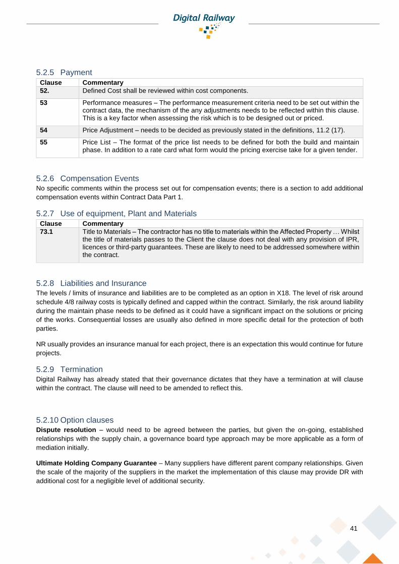
41
5.2.5 Payment
Clause Commentary
52. Defined Cost shall be reviewed within cost components.
53 Performance measures – The performance measurement criteria need to be set out within the contract data, the mechanism of the any adjustments needs to be reflected within this clause. This is a key factor when assessing the risk which is to be designed out or priced.
54 Price Adjustment – needs to be decided as previously stated in the definitions, 11.2 (17).
55 Price List – The format of the price list needs to be defined for both the build and maintain phase. In addition to a rate card what form would the pricing exercise take for a given tender.
5.2.6 Compensation Events No specific comments within the process set out for compensation events; there is a section to add additional
compensation events within Contract Data Part 1.
5.2.7 Use of equipment, Plant and Materials
Clause Commentary
73.1 Title to Materials – The contractor has no title to materials within the Affected Property … Whilst the title of materials passes to the Client the clause does not deal with any provision of IPR, licences or third-party guarantees. These are likely to need to be addressed somewhere within the contract.
5.2.8 Liabilities and Insurance The levels / limits of insurance and liabilities are to be completed as an option in X18. The level of risk around
schedule 4/8 railway costs is typically defined and capped within the contract. Similarly, the risk around liability
during the maintain phase needs to be defined as it could have a significant impact on the solutions or pricing
of the works. Consequential losses are usually also defined in more specific detail for the protection of both
parties.
NR usually provides an insurance manual for each project, there is an expectation this would continue for future
projects.
5.2.9 Termination Digital Railway has already stated that their governance dictates that they have a termination at will clause
within the contract. The clause will need to be amended to reflect this.
5.2.10 Option clauses Dispute resolution – would need to be agreed between the parties, but given the on-going, established
relationships with the supply chain, a governance board type approach may be more applicable as a form of
mediation initially.
Ultimate Holding Company Guarantee – Many suppliers have different parent company relationships. Given
the scale of the majority of the suppliers in the market the implementation of this clause may provide DR with
additional cost for a negligible level of additional security.

42
Undertakings to others – Given the complex structure of the UK rail industry it is likely over a long-term period,
in a digital environment, that information or services may be supplied to other parties, such as TOC’s. There
may not be any benefit to precluding it from an OJEU notification however initially there may not be a
requirement.
Transfer of rights – Similar to IPR this section would likely need to be expanded given that hardware and
software will form part of the scope.
Information Modelling – The use of BIM is unlikely to add value to the project however information systems
are likely to add value. What information these systems hold and how it is used form part of the potential of a
digital solution.
Performance bond – the risk of the supplier’s performance would have to be assessed by the client, would the
cost of a bond offer value over a long-term agreement?
Advanced Payment – Not common in NR contracts unless an initial outlay is required.
Limitation of Liability – to be defined in accordance with the values in the Contract Data.
Extension of the service period – The conditions, timing and value of the extension would have to be defined.
Housing Grants Act and the Contract Act are likely to apply for UK contracts.
Z - Clauses would need to be defined relevant to the project.
5.3 Cost Components Many of the supply chain work in a mature target cost environment and have an agreed position on the elements
that constitute the Actual Cost and the elements that make up the fee. Often a schedule of labour rates is used
instead of individuals actual cost to ensure that administering the contract is timelier and cost effective. All costs
are made available for NR to audit centrally. Given that suppliers and NR have worked to these standards and
they are agreed across much of the supply chain in may be worth looking to use the cost components within
the ICE framework agreements instead of the NEC definition.
Aligning the schedule of cost components to the contract which is to be used for any new CP6 framework
agreements will also bring savings to the suppliers and DR.
The makeup of the project is likely to include significant amounts of internal labour and therefore it may be
beneficial to have set labour rates or a rate card instead of auditing the make-up of 10’individual’s costs.
5.4 NEC4 vs NR12 terms and proposed additional terms When using a standard form of contract there will inevitably be changes required to ensure that the contract is
workable given its specific requirements, environment and constraints. A review has been undertaken
comparing the base NEC4 Design Build and Operate terms to those of a NR12 S&T contract. Appendix 1
proposes wording for terms that the suppliers believe would need to be amended or added in order to make the
contract workable. The appendix covers:
• Insurance
• Liabilities
• Client Options

43
• Care of the works and handback
• Railway Costs
• Intellectual property rights
• CDM regulations
• Prohibitive Materials
• Construction Industry Scheme
• Confidentiality
• Track access
The appendix also references the clause number within an NR12 contract to demonstrate the current wording
agreed with Network Rail. The NR12 contract has evolved over a number of years and been refined as a result
of the delivery of a significant number of schemes. It would make sense to use this learning and to continue
with the agreed wording where applicable for the Moorgate contract.
5.5 Suppliers approach to contract risk When creating a payment model within the NEC4 framework there is opportunity to create an incentive model
to ensure that the outcome based specification remains the contractual focus. One proposed model is that the
Supplier puts all or part of their fee at risk until an outcome milestone is met. The costs are paid throughout the
duration of the project, subject to the pain/gain mechanism, to provide cash flow to the supply chain and
confidence that the fair payment charter is being upheld. Having the Fee withheld until outcome based criteria
are met ensures that the focus remains on delivering the specific outcome. For differing projects the goals may
be different, for some it may be timely delivery for example to meet other stakeholders delivery dates, for
instance new rolling stock. Another might be reliability performance given the high impact nature of certain parts
of the network should they fail. The Suppliers are accepting to put the fee at risk on an outcome however also
expect to be rewarded if they can provide additional benefits which are agreed with the customer.
When creating an incentive model an outcome based specification should set out the main goals of the customer
and the contracting mechanism must align these with those of the contractor. A framework model allows an
environment where closer working and understanding can be achieved. For example if a section or Railway,
like the Moorgate line, has life expired maintenance issues then the supplier could be rewarded for delivering a
solution faster, saving the customer money on delay costs and improving the end user experience. If the goals
of the customer are not aligned with those of the contract, then a misalignment can cause friction between the
parties who will focus their efforts on different priorities.

44
6 Maintenance Contracting
6.1 Background The majority of the mainline signalling installations within Great Britain are currently maintained by Network Rail
staff. Suppliers are typically asked to provide 3rd line technical support for the technologies that they have
installed and legacy equipment that is still in use on the railway. Suppliers also provide repairs and spares
service and often manage obsolescence of the systems within their working lifetime, and often beyond their
original design life.
As the maintenance activities are undertaken by NR, the supply chain have little involvement in the undertaking
or the decision making process when it comes to developing maintenance strategies.
Typical warranty periods for signalling equipment installed on current schemes are 2 years, however the design
life is significantly longer.
The risks attributed with the maintenance of the equipment is almost entirely with NR including the risk of
Schedule 4 & Schedule 8 payments for when the railway is closed for maintenance or is not available because
of equipment faults. Within the supply chain there is not currently an understanding of the costs involved, or the
process of how costs are attributed, between stakeholders because of preventative or reactive maintenance.
The supply chain has, however, acknowledged that to remain competitive and best serve its clients it needs to
provide products that not only reduce the capital costs but help to reduce the operational cost including
maintenance. As technology continues to develop more products have diagnostics that can notify the maintainer
of their performance, or of any failures. As more data is gathered to understand the performance of products
artificial intelligence can be introduced to predict failures before they occur. This forms part of the benefits of a
Digital Railway.
Outside of Great Britain, it is common for suppliers to take on the operation and maintenance of the railway
infrastructure. This is however usually based on deploying staff directly from within their organisation. The
transition of responsibilities for the maintenance of GB infrastructure will need to be carefully managed.
6.2 Managing Change Changing supplier – client roles, responsibilities and processes is extremely complicated operation and one that
this section will not try to address. It would be worth acknowledging however that a framework arrangement that
allows for flexibility would assist in facilitating the transition. Suppliers could be incentivised to provide
continuous improvement in supporting maintenance activities. Targets may not be able to be set at the tender
stage however mechanisms could be agreed to periodically reassess and reset these targets. Within other
industries where long term maintenance agreements are in place contract extensions are often based upon,
innovation, engagement and KPI’s that are not necessarily defined at the tender phase.
The suppliers may not be able to move to a position where they take liability for the operation of the railway but
suppliers are willing to put “skin in the game” and start to move in that direction.
6.3 Maintenance Scope This section looks to provide DR with some potential maintenance options that the supply chain could provide.
The diagram below provides some of the headings that make up the total lifecycle management of a product.
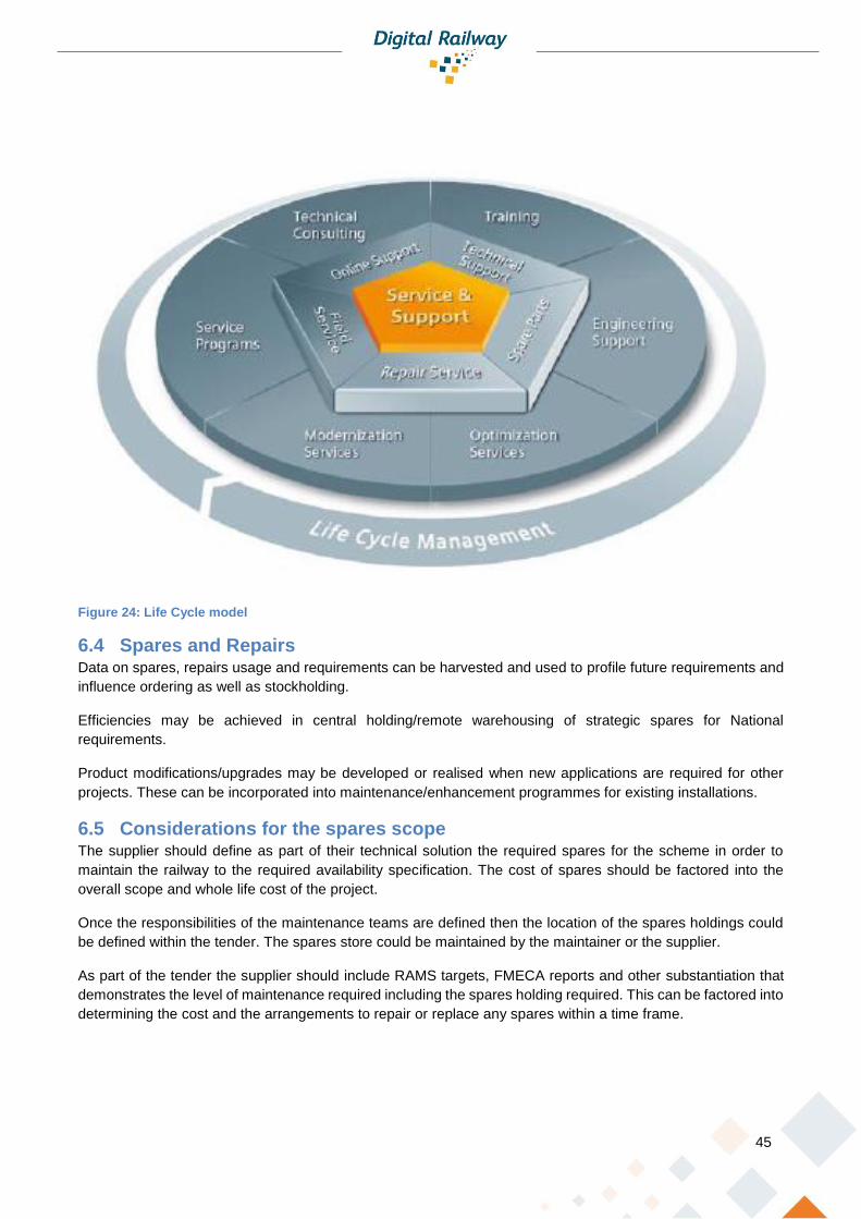
45
Figure 24: Life Cycle model
6.4 Spares and Repairs Data on spares, repairs usage and requirements can be harvested and used to profile future requirements and
influence ordering as well as stockholding.
Efficiencies may be achieved in central holding/remote warehousing of strategic spares for National
requirements.
Product modifications/upgrades may be developed or realised when new applications are required for other
projects. These can be incorporated into maintenance/enhancement programmes for existing installations.
6.5 Considerations for the spares scope The supplier should define as part of their technical solution the required spares for the scheme in order to
maintain the railway to the required availability specification. The cost of spares should be factored into the
overall scope and whole life cost of the project.
Once the responsibilities of the maintenance teams are defined then the location of the spares holdings could
be defined within the tender. The spares store could be maintained by the maintainer or the supplier.
As part of the tender the supplier should include RAMS targets, FMECA reports and other substantiation that
demonstrates the level of maintenance required including the spares holding required. This can be factored into
determining the cost and the arrangements to repair or replace any spares within a time frame.
46
6.6 Technical Support 1st Line site support: Enhanced site support could be provided 24 hours a day, 7 days a week after the initial
entry into service. It is common for the maintainer to often request this cover post a major commissioning in
case any initial faults occur. The supplier will often provide commissioning spares to avoid failures affecting the
railway during this infant mortality phase.
2nd Line support: During the period of enhanced site support a competent ETCS supplier could be required to
attend site within 24 hours of receiving the request. This option could be implemented for an initial period until
the maintainer is fully confident in managing the new equipment. The duration of this period could be flexible
and may be a function of the quality of the training that has been provided.
3rd Line Support: Telephone support could be provided by the supplier to answer all technical queries. The
telephone support could be available during office hours on working days or 24/7 depending on the railway
regime. When the telephone support is not available the supplier could provide an answering service such that
a message can be left and the supplier shall return the call when the telephone support is next available.
The telephone support will typically provide:
• Over the phone assistance with problems with repaired items;
• Over the phone assistance with the diagnostics on faults;
• Over the phone assistance with component history; and
• Discussion regarding second No Fault Founds (NFF) and next steps.
The traditional 3rd line technical support can be enhanced by remote monitoring of anything from individual
components to mock ups of complete systems. Any faulting issues arising can be quickly understood and
performance diagnostics can be run remotely with solutions being devised in a controlled environment.
By more long-term data gathering and sharing, the life of components can be modelled. This has the potential
to assist in the understanding of reactive maintenance and the planning of preventative maintenance. The
further into the life cycle and the more projects that exist with a supplier, the greater the data and the more
accurate the model. Contracts could be extended based upon the value that the supplier continues to offer, this
feedback loop would also benefit future products where any weaknesses or sub optimisation of the system
could quickly be addresses.
6.7 Technical Investigation In addition to the supplier providing reports on defect analysis and trends, they shall also, on request, undertake
specific investigations into failures, incidents and any other unexpected behaviour of the ETCS system.
Technical investigations are often required where different systems interface with each other to understand the
reasons for failures.
6.8 Testing Equipment, Special Tools and Training Equipment The supplier shall maintain all testing equipment, special tools, maintenance training rigs, and additional
software updates associated with the ETCS system in service for the duration of the project.
6.9 Managing obsolescence The supplier would have to monitor the availability of parts such that the installed equipment remained
maintainable. Where such parts could not be obtained, the supplier would have to provide alternative solutions
to ensure the system remains operable.

47
If a maintenance agreement were to last 30 years at some point there may need to be an update to the
equipment. Certain components or software may no longer be supported and therefore updating equipment
may continue to keep the system operable and extend the life of the system.
When selecting a supplier, the client would need to consider the supplier’s historic record of managing
obsolescence as an important indicator of how well they intend to maintain their current products.
6.10 Network and Cyber Security Management As the railway advances into an ever more digital environment the supplier would need to ensure that the
systems controlling the railway maintain secure.
Where information transfers from the project network on to the national network the protocols and security would
need to be agreed with NRT to ensure the systems remain safe and operational. Careful consideration will need
to be given where remote access to systems is required by the supplier to provide 3rd line support which would
invariably mean remote access to safety related and safety critical systems from a point external to the NR
telecommunications infrastructure.
The supplier should provide a maintenance strategy and process to ensure that networks remain protected
during the maintenance phase.
6.11 Key Performance Indicators Common performance indicators for the maintenance period could include:
• Maintenance of the reliability targets
• Achievement of the lead times for provision of new spares
• Achievement of the lead times for repaired spares
• Response to queries to the telephone service within the required times
• Inputting data concerning the occurrence and rectification of defects into DRACAS
KPI’s could be used as an incentive for the supplier to perform throughout the life of the contract. Monthly
maintenance payments could be awarded based upon the performance against the KPI performance, with a
reduced payment should the supplier not meet the required targets.
6.12 Reliability Targets and performance The ETCS system would initially have a reliability target to be achieved. During the maintenance phase and
during subsequent deployments along a route, the supplier could be rewarded for improving upon the reliability
target. This would incentivise the supplier to continuously develop the reliability of their products. Products could
be systematically upgraded in future years to increase reliability, creating a win-win situation for both the
maintainer and the supplier.
Should the reliability target not be met then the supplier would be penalised. This could be a function of the
periodic maintenance payment based upon the number of failures within the period. Should the supplier not
meet the minimum maintenance requirement then no maintenance payment would be received.
6.13 Maintenance reporting A periodic maintenance report could include the following:
• any failure to maintain a reliability target;
• any incentive payments of deductions

48
• any failure to meet a lead time for new spares with the reasons for the delay and steps being taken
to prevent delay from occurring again;
• any deductions to be made in respect of failure to deliver new spares by the relevant lead time
• any failure to meet a lead time for repaired spares with the reasons for the delay and steps being
taken to prevent delay from occurring again;
• any deductions to be made as a result of failure to deliver repaired spares by the lead time;
• any failure to return calls within the response time or, where such calls were returned in the
Response Time it was not by an appropriately qualified engineer;
• any failure to input defects into a DRACAS as required.
• any draft remedial performance improvement plans;
• any other service failures together with the information required;
• whether a persistent service failure has occurred or is likely to occur; and
• any other information which is related to the performance of the Service, maintenance of the
reliability target and the achievement (or otherwise) of the KPIs or as may be requested by the
Employer.
6.14 Tender Format The format of the tender documentation will need to reflect the use of an Outcome Based Specification. The
proposed arrangement as shown in Figure 25 provides a structured approach.
Figure 25: Proposed Tender Document Structure
The Core Document contains the overview documentation associated with the project including an overview,
the geographical boundaries and the ABR.

49
The Infrastructure Data contains the documents and data that describe the infrastructure that the project will
be implemented upon including the existing asset data, constraints and possession planning information.
The Functional, Process and Non-Functional Requirements are consolidated into the Application High Level
Outcomes (CRD) that describes all the requirements as either functional, non-functional or as process
requirements.
The Preliminary Schedule provides the programme and phases of work including the key milestones and
interfaces with associated and adjacent projects. For a Design, Build and Maintain project, this will include the
period of the maintenance period including renewals and obsolescence matters.
The O&M section provides information regarding the current operating documentation including training issues
and the asset management regime for the route.
The Commercial section sets out the commercial and contractual arrangements for the project.

50
7 Risks and challenges
7.1 Cultural Changes Adopting a “thin” client organisation may introduce culture shock to the project delivery and technical assurance
teams. Whilst it is understood that the current arrangements are no longer fit for purpose, the transition to a new
“thin organisation” will introduce several challenges.
It should be expected that the transition will be jarring with each organisation trying to understand their new
roles. There is a risk that as each organisation flexes into their new roles as RSIP and Technical Integrator that
critical tasks are duplicated or omitted. This would cause confusion and conflict between the teams and
resistance to the new process.
This risk could be mitigated by deploying a “business change management team” that
would be independent and oversee that the process to ensure that the works are
being conducted in accordance with the strategy. They would provide guidance to the
teams and ensure “fair play” was maintained during the transition period.
Whilst this report, retains the current job titles (i.e. DPE) this
is to provide understanding. To provide a clear differential from the existing
organisation to the new one, it is recommended that job titles are revised and aligned
with the new responsibilities. This would provide a clear delineation from the current
and allow new attitudes and behaviours to be established.
7.2 System of Systems The V-Life cycle provides the opportunity to the supplier to provide a bespoke and tailored solution that makes
best use of the generic specifications, the application requirements and their products.
However, their solution will reside in a wider system (the System of Systems (SoS)) that it will need to reside
within to ensure that it can provide interoperability.
Now, the generic specifications provide the requirements for achieving the M9 state and these requirements
need to be preserved in each application to ensure the systems will be interoperable.
There is a risk that the generic specifications could constrain the application requirements and the supplier. It is
understood that the generic specifications have been designed to be flexible and supplier agnostic but this has
not been tested.
7.3 Systems Authority The ability to tailor requirements to specific applications will require assurance that the tailoring does not affect
the System of Systems approach required to assure the interoperability of the systems provided by individual
projects.
This report supports Digital Rail’s intent to have a Systems Authority that will preside over the Specifications to
ensure that the interoperability of systems is persevered.
The ability to provide guidance in the production of requirements throughout the project lifecycle by using
templates and guidance notes would also help to mitigate deviations and manage the assurance of the generic
requirements.

51
This report recommends further consideration of templates for the project management plans (both delivery and
engineering), assurance and V&V plans, and testing reporting.
7.4 Technical Changes Required Following completion of the surveys it is vital that the railway configuration is
managed. The functionality of an ETCS system is defined in the configuration data.
This data has to match that of the actual railway. Divergence between the data and
the actual railway can result in expensive re-work cycles.
Further collaboration between the Technical Integrator
and Network Rail Telecoms is required as the FTNx and
GSM-R systems are now core to the delivery of the signalling system. This will require
a culture change in NRT as they will no longer be integrating with the IP signalling
team but with a System Integrator as IP signalling operate as a Railway Systems
Integrator in the Thin Client Model.
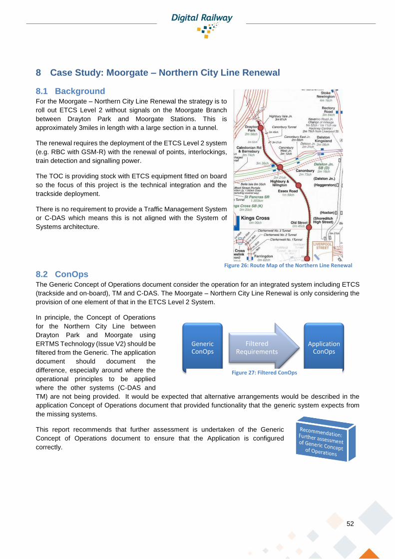
52
8 Case Study: Moorgate – Northern City Line Renewal
8.1 Background For the Moorgate – Northern City Line Renewal the strategy is to
roll out ETCS Level 2 without signals on the Moorgate Branch
between Drayton Park and Moorgate Stations. This is
approximately 3miles in length with a large section in a tunnel.
The renewal requires the deployment of the ETCS Level 2 system
(e.g. RBC with GSM-R) with the renewal of points, interlockings,
train detection and signalling power.
The TOC is providing stock with ETCS equipment fitted on board
so the focus of this project is the technical integration and the
trackside deployment.
There is no requirement to provide a Traffic Management System
or C-DAS which means this is not aligned with the System of
Systems architecture.
8.2 ConOps The Generic Concept of Operations document consider the operation for an integrated system including ETCS
(trackside and on-board), TM and C-DAS. The Moorgate – Northern City Line Renewal is only considering the
provision of one element of that in the ETCS Level 2 System.
In principle, the Concept of Operations
for the Northern City Line between
Drayton Park and Moorgate using
ERTMS Technology (Issue V2) should be
filtered from the Generic. The application
document should document the
difference, especially around where the
operational principles to be applied
where the other systems (C-DAS and
TM) are not being provided. It would be expected that alternative arrangements would be described in the
application Concept of Operations document that provided functionality that the generic system expects from
the missing systems.
This report recommends that further assessment is undertaken of the Generic
Concept of Operations document to ensure that the Application is configured
correctly.
Generic ConOps
Filtered Requirements
Application ConOps
Figure 27: Filtered ConOps
Figure 26: Route Map of the Northern Line Renewal
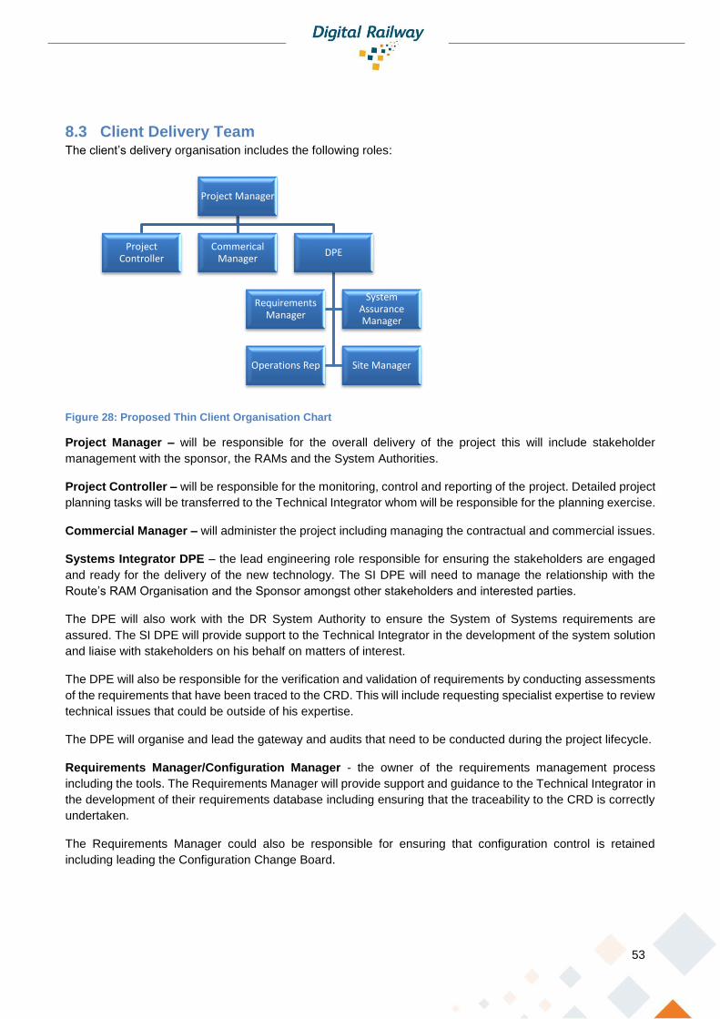
53
8.3 Client Delivery Team The client’s delivery organisation includes the following roles:
Figure 28: Proposed Thin Client Organisation Chart
Project Manager – will be responsible for the overall delivery of the project this will include stakeholder
management with the sponsor, the RAMs and the System Authorities.
Project Controller – will be responsible for the monitoring, control and reporting of the project. Detailed project
planning tasks will be transferred to the Technical Integrator whom will be responsible for the planning exercise.
Commercial Manager – will administer the project including managing the contractual and commercial issues.
Systems Integrator DPE – the lead engineering role responsible for ensuring the stakeholders are engaged
and ready for the delivery of the new technology. The SI DPE will need to manage the relationship with the
Route’s RAM Organisation and the Sponsor amongst other stakeholders and interested parties.
The DPE will also work with the DR System Authority to ensure the System of Systems requirements are
assured. The SI DPE will provide support to the Technical Integrator in the development of the system solution
and liaise with stakeholders on his behalf on matters of interest.
The DPE will also be responsible for the verification and validation of requirements by conducting assessments
of the requirements that have been traced to the CRD. This will include requesting specialist expertise to review
technical issues that could be outside of his expertise.
The DPE will organise and lead the gateway and audits that need to be conducted during the project lifecycle.
Requirements Manager/Configuration Manager - the owner of the requirements management process
including the tools. The Requirements Manager will provide support and guidance to the Technical Integrator in
the development of their requirements database including ensuring that the traceability to the CRD is correctly
undertaken.
The Requirements Manager could also be responsible for ensuring that configuration control is retained
including leading the Configuration Change Board.
Project Manager
Project Controller
Commerical Manager
DPE
Requirements Manager
System Assurance Manager
Operations Rep Site Manager
54
ETCS Operations Representative – is the operation facing team member and will be responsible for ensuring
the ETCS system is ready for operations including working with the TOCs. He/she will provide guidance to the
team and the Technical Integrator regarding Concept of Operation matters.
Site Manager – will be involved during the implementation phase and be responsible for assuring that the CDM
obligations are being met by the Technical Integrator. The Site Manager will undertake inspection and test
witnessing activities as required.
Safety Assurance Manager – will manage the Safety Assurance process in accordance with CSM principles.
The SAM will manage the relationship with the Regulator, ISA and other safety bodies that would be required
by the project.
The SAM will provide direction to the Technical Integrator in the development of their safety argument and
ensure that the various Safety Cases are correctly integrated.
8.4 Engineering Structure Figure 29 provides a proposed engineering structure for the Moorgate Project.
The arrangement places the Client engineering team in the centre of the project acting as the RSIP between
the technical activities being conducted by the supplier and the Sponsors, the Users (RAMs/TOC/etc.) and the
Authorities (Digital Rail, ISA, Regulator, etc.).
The RSIP role will require a dynamic team that are prepared to work in a co-operative and pragmatic way to
ensure that the new model is given the chance to evolve and develop into a working solution.
The Technical Integrator role will manage the delivery of critical activities integrating together the various
disciplines into a cohesive solution. Under this structure, key tasks such as Design Assurance, Quality
Assurance and Safety Management will now have to be conducted by the Technical Integrator with little
oversight from the RSIP. Whilst the Supply Chain has considerable experience of undertaking this role on many
overseas mainline and metro projects, this project will be novel in many respects not least because it affects
the established standards and procedures for project delivery on the GB network. Like the RSIP’s team, the
Technical Integrator will need to deploy practical and pragmatic engineers to work in an emerging and evolving
project delivery environment.

55
Requirements
Manager
Configuration
Manager
Sys Int /DPE
GTR
ETCS Operation
s Rep
Safety Assurance Manager
Siemens Class 717
Alstom Class 313
CEM
CRE IXL/
Trackside
CREETCS
CRETrack
Safety Assurance
Assessor
Product Assurance
Technical Integrator
Maintainer 2nd Line
CRECivils
CRETraction
CREPway
Test
CRE Control Centre
Safety Assurance Manager
V&V Lead
NoBo (TSI)
ISA
DeBo (NTR)
AsBo
Train Dispatch
CRE Telecoms
CREPower
RAMTrack
RAMCivils
RAMTraction
RAMPway
RAM Telecoms
RAMPower
Local Mtce
Site Manager
ORR (safety
authority)
ERA(tech
pillar 4th Railway
package)
Test Manager
Trainers
Signal Sighting
Chair
Sponsor
NRT
Passenger flow control
Evacuation plans
Rostering
Possession
Planning
Figure 29: Proposed Organisational Relationships for Moorgate Project

56
Appendix 1 Proposal for Signalling & Telecoms specific amendments to NEC 4 Design, Build and Operate Contract (June 2017)
Clause Proposal Comment Comparison NR12 (S&T) Clause
Proposed Optional Clauses
X15 X15.1 The Contractor is not liable for a Defect which arose from its design unless it failed to carry out that design using the skill and care normally used by professionals designing works similar to the works.
X15.2 The Contractor corrects a Defect for which it is not liable under the contract as a compensation event. X15.3 The Contractor may use the material provided by it under the contract for other work unless
• ownership of the material has been given to the Client
• it is stated otherwise in the Scope X15.4 The Contractor retains copies of drawings, specifications, reports and other documents which record the
Contractor’s design for the period of retention. The copies are retained in the form stated in the Scope.
▪ This is the standard NEC 4 Option X15 clause, with the exception of X15.5. X15.5 has been omitted on the understanding that required insurance will be set-out in a single location, in the insurance table within Core Clause 83.3.
▪ Set-out the general duty for reasonable skill and care for design. ▪ Only X15.1 and X15.2 would be required to maintain the existing principles, but
X15.3 and X15.4 are proposed as potentially helpful clarifications.
Clause 8(2)
X18 X18.1 Each of the limits to the Contractor’s liability in this clause apply if a limit is stated in the Contract Data. X18.2 The liability of each party to the other for any loss of profit, loss of use (including without limitation loss of use
of infrastructure or railway vehicles), loss of production, financial loss, loss of contracts, loss of data or information or for any indirect or consequential loss is limited to the amount stated in the Contract Data.
X18.3 For any one event the liability of the Contractor to the Client for loss or damage to the Client’s property is limited to the amount stated in the Contract Data.
X18.4 The Contractor’s liability to the Client for Defects due to its design is limited to the amount in the Contract Data. X18.5 The Contactor’s total liability to the Client for all matters arising under or in connection with the contract, other
than the excluded matters, is limited to the amount state in the Contract Data. The excluded matters are amounts payable by the Contractor for:
• any liability in respect of death or personal injury resulting from a negligent act or omission or breach of statutory duty by the Contractor or any person for whom the Contractor is responsible;
• any losses directly caused by the fraud of the Contractor. X18.6 The Contractor is not liable to the Client for any matter unless it is notified to the Contractor before the end of
liability date. X18.7 The limitations and exclusions of liability in the contract apply to any breach of contract or statutory duty, tort
(including but not limited to negligence), delict, by way of indemnity or otherwise to the extent allowed under the law of the contract.
▪ Proposes an amended Clause X18 to capture the currently agreed S&T position regarding limitations and exclusions of liability.
▪ X18.2 captures current exclusion of liability provisions within the S&T conditions.
It is assumed that the liability value in the Contract Data would be “£0”. Given the nature of the ETCS works an expansion of the language is proposed. For transparency the operative additional words are underlined in blue for NR’s consideration. As with the existing S&T provisions it is proposed that this clause also applies for the benefit of NR.
▪ X18.5 under the equivalent clause of the NR12(S&T) conditions [clause 88],
insured design liability would also be covered by a separate cap of £10 million. For transparency, this statement has not been proposed here, as it is understood that the design liability cap would be covered by X18.4.
Clause 88 and Clause 8(2)(c)
New X24 Client’s Options
X.24.1 Client’s options are those elements of service stated in the Contract Data which, if requested by the Client on or before the relevant date stated in the Contract Data, shall be undertaken by the Contractor in accordance with this clause.
X.24.2 The Client gives an instruction for perform any or all of the Client’s Options on or before the relevant date stated in the Contract Data. The Client’s instruction to perform a Client’s option is a compensation event.
X24.3 Compensation events instructed under this clause shall be assessed as follows:
• The addition to the Prices is the itemised sum against each Client’s option unless any changes to the services in the relevant Client’s option have been made.
• Any changes to the services in the relevant Client’s option shall be assessed as compensation events and the relevant Price(s) established shall be adjusted either up, or down accordingly.
X24.4 No extension of time shall be allowable as a result of any Client’s option instructed under this clause. For the avoidance of doubt, any subsequent alteration to the services to be delivered pursuant to and following the instruction a Client’s option shall be assessed as a compensation event.
▪ Creates the ability for the contract to include priced options within the scope; which NR has the right to exercise up to the, programme driven, date for exercise of that option.
Clauses 1(1) and 89.
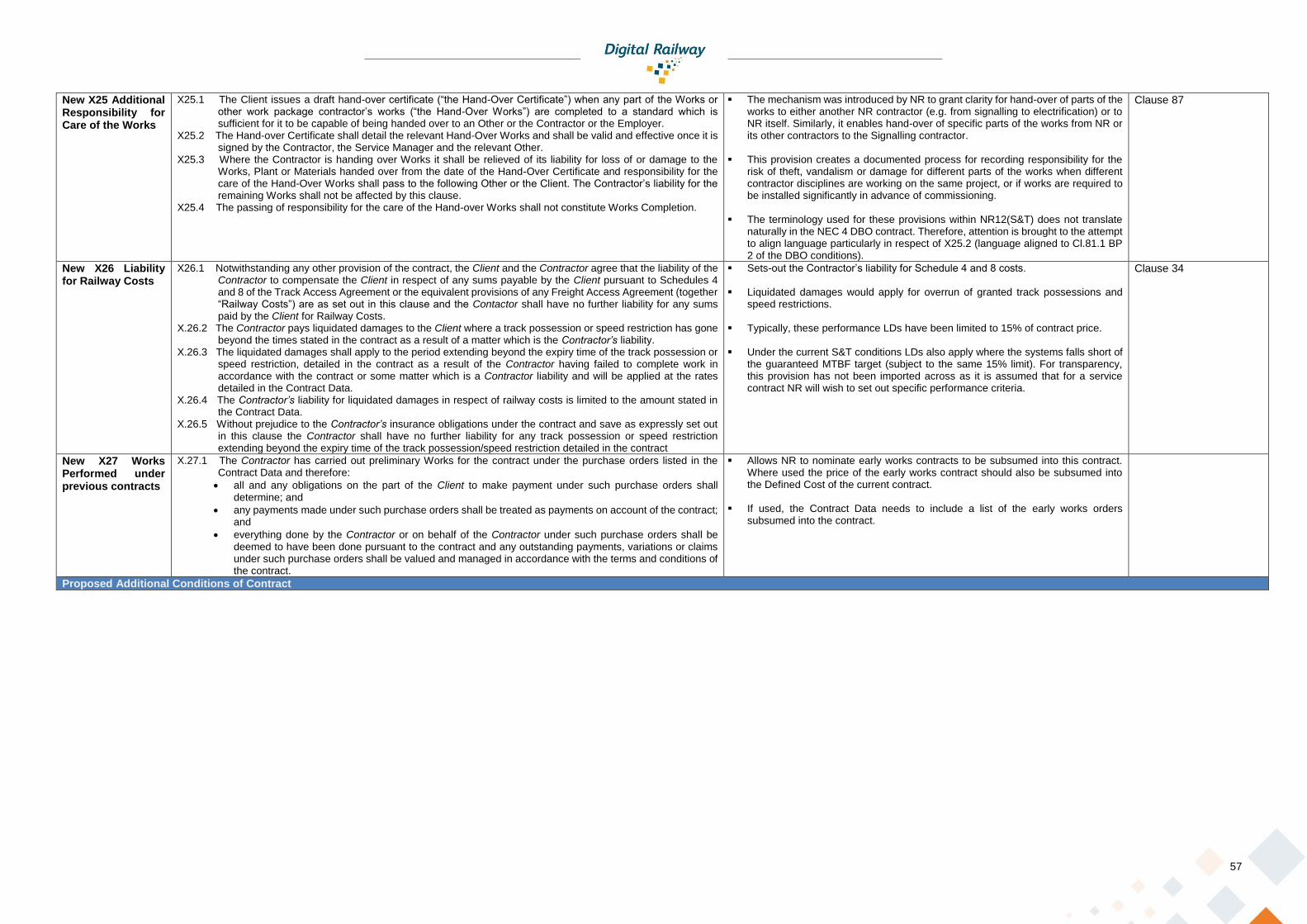
57
New X25 Additional Responsibility for Care of the Works
X25.1 The Client issues a draft hand-over certificate (“the Hand-Over Certificate”) when any part of the Works or other work package contractor’s works (“the Hand-Over Works”) are completed to a standard which is sufficient for it to be capable of being handed over to an Other or the Contractor or the Employer.
X25.2 The Hand-over Certificate shall detail the relevant Hand-Over Works and shall be valid and effective once it is signed by the Contractor, the Service Manager and the relevant Other.
X25.3 Where the Contractor is handing over Works it shall be relieved of its liability for loss of or damage to the Works, Plant or Materials handed over from the date of the Hand-Over Certificate and responsibility for the care of the Hand-Over Works shall pass to the following Other or the Client. The Contractor’s liability for the remaining Works shall not be affected by this clause.
X25.4 The passing of responsibility for the care of the Hand-over Works shall not constitute Works Completion.
▪ The mechanism was introduced by NR to grant clarity for hand-over of parts of the works to either another NR contractor (e.g. from signalling to electrification) or to NR itself. Similarly, it enables hand-over of specific parts of the works from NR or its other contractors to the Signalling contractor.
▪ This provision creates a documented process for recording responsibility for the risk of theft, vandalism or damage for different parts of the works when different contractor disciplines are working on the same project, or if works are required to be installed significantly in advance of commissioning.
▪ The terminology used for these provisions within NR12(S&T) does not translate
naturally in the NEC 4 DBO contract. Therefore, attention is brought to the attempt to align language particularly in respect of X25.2 (language aligned to Cl.81.1 BP 2 of the DBO conditions).
Clause 87
New X26 Liability for Railway Costs
X26.1 Notwithstanding any other provision of the contract, the Client and the Contractor agree that the liability of the Contractor to compensate the Client in respect of any sums payable by the Client pursuant to Schedules 4 and 8 of the Track Access Agreement or the equivalent provisions of any Freight Access Agreement (together “Railway Costs”) are as set out in this clause and the Contactor shall have no further liability for any sums paid by the Client for Railway Costs.
X.26.2 The Contractor pays liquidated damages to the Client where a track possession or speed restriction has gone beyond the times stated in the contract as a result of a matter which is the Contractor’s liability.
X.26.3 The liquidated damages shall apply to the period extending beyond the expiry time of the track possession or speed restriction, detailed in the contract as a result of the Contractor having failed to complete work in accordance with the contract or some matter which is a Contractor liability and will be applied at the rates detailed in the Contract Data.
X.26.4 The Contractor’s liability for liquidated damages in respect of railway costs is limited to the amount stated in the Contract Data.
X.26.5 Without prejudice to the Contractor’s insurance obligations under the contract and save as expressly set out in this clause the Contractor shall have no further liability for any track possession or speed restriction extending beyond the expiry time of the track possession/speed restriction detailed in the contract
▪ Sets-out the Contractor’s liability for Schedule 4 and 8 costs.
▪ Liquidated damages would apply for overrun of granted track possessions and speed restrictions.
▪ Typically, these performance LDs have been limited to 15% of contract price.
▪ Under the current S&T conditions LDs also apply where the systems falls short of the guaranteed MTBF target (subject to the same 15% limit). For transparency, this provision has not been imported across as it is assumed that for a service contract NR will wish to set out specific performance criteria.
Clause 34
New X27 Works Performed under previous contracts
X.27.1 The Contractor has carried out preliminary Works for the contract under the purchase orders listed in the Contract Data and therefore:
• all and any obligations on the part of the Client to make payment under such purchase orders shall determine; and
• any payments made under such purchase orders shall be treated as payments on account of the contract; and
• everything done by the Contractor or on behalf of the Contractor under such purchase orders shall be deemed to have been done pursuant to the contract and any outstanding payments, variations or claims under such purchase orders shall be valued and managed in accordance with the terms and conditions of the contract.
▪ Allows NR to nominate early works contracts to be subsumed into this contract. Where used the price of the early works contract should also be subsumed into the Defined Cost of the current contract.
▪ If used, the Contract Data needs to include a list of the early works orders subsumed into the contract.
Proposed Additional Conditions of Contract
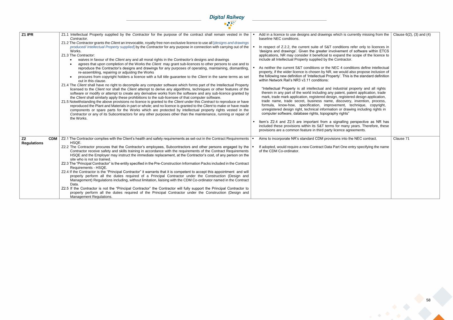
58
Z1 IPR Z1.1 Intellectual Property supplied by the Contractor for the purpose of the contract shall remain vested in the Contractor.
Z1.2 The Contractor grants the Client an irrevocable, royalty free non-exclusive licence to use all [designs and drawings produced/ Intellectual Property supplied] by the Contractor for any purpose in connection with carrying out of the Works.
Z1.3 The Contractor:
• waives in favour of the Client any and all moral rights in the Contractor’s designs and drawings
• agrees that upon completion of the Works the Client may grant sub-licences to other persons to use and to reproduce the Contractor’s designs and drawings for any purposes of operating, maintaining, dismantling, re-assembling, repairing or adjusting the Works
• procures from copyright holders a licence with a full title guarantee to the Client in the same terms as set out in this clause.
Z1.4 The Client shall have no right to decompile any computer software which forms part of the Intellectual Property licensed to the Client nor shall the Client attempt to derive any algorithms, techniques or other features of the software or modify or attempt to create any derivative works from the software and any sub-licence granted by the Client shall similarly apply these prohibitions to the sub-licensee of that computer software.
Z1.5 Notwithstanding the above provisions no licence is granted to the Client under this Contract to reproduce or have reproduced the Plant and Materials in part or whole; and no licence is granted to the Client to make or have made components or spare parts for the Works which are protected by intellectual property rights vested in the Contractor or any of its Subcontractors for any other purposes other than the maintenance, running or repair of the Works.
▪ Add in a licence to use designs and drawings which is currently missing from the baseline NEC conditions.
▪ In respect of Z.2.2, the current suite of S&T conditions refer only to licences in
‘designs and drawings’. Given the greater involvement of software within ETCS applications, NR may consider it beneficial to expand the scope of the licence to include all Intellectual Property supplied by the Contractor.
▪ As neither the current S&T conditions or the NEC 4 conditions define intellectual
property, if the wider licence is chosen by NR, we would also propose inclusion of the following new definition of ‘Intellectual Property’. This is the standard definition within Network Rail’s NR3 v3.11 conditions:
“Intellectual Property is all intellectual and industrial property and all rights therein in any part of the world including any patent, patent application, trade mark, trade mark application, registered design, registered design application, trade name, trade secret, business name, discovery, invention, process, formula, know-how, specification, improvement, technique, copyright, unregistered design right, technical information or drawing including rights in computer software, database rights, topography rights”
▪ Item’s Z2.4 and Z2.5 are important from a signalling perspective as NR has
included these provisions within its S&T terms for many years. Therefore, these provisions are a common feature in third party licence agreements.
Clause 6(2), (3) and (4)
Z2 CDM Regulations
Z2.1 The Contractor complies with the Client’s health and safety requirements as set-out in the Contract Requirements HSQE.
Z2.2 The Contractor procures that the Contractor’s employees, Subcontractors and other persons engaged by the Contractor receive safety and skills training in accordance with the requirements of the Contract Requirements HSQE and the Employer may instruct the immediate replacement, at the Contractor’s cost, of any person on the site who is not so trained.
Z2.3 The “Principal Contractor” is the entity specified in the Pre-Construction Information Packs included in the Contract Requirements - HSQE.
Z2.4 If the Contractor is the “Principal Contractor” it warrants that it is competent to accept this appointment and will properly perform all the duties required of a Principal Contractor under the Construction (Design and Management) Regulations including, without limitation, liaising with the CDM Co-ordinator named in the Contract Data.
Z2.5 If the Contractor is not the “Principal Contractor” the Contractor will fully support the Principal Contractor to properly perform all the duties required of the Principal Contractor under the Construction (Design and Management Regulations.
▪ Aims to incorporate NR’s standard CDM provisions into the NEC contract.
▪ If adopted, would require a new Contract Data Part One entry specifying the name of the CDM Co-ordinator.
Clause 71
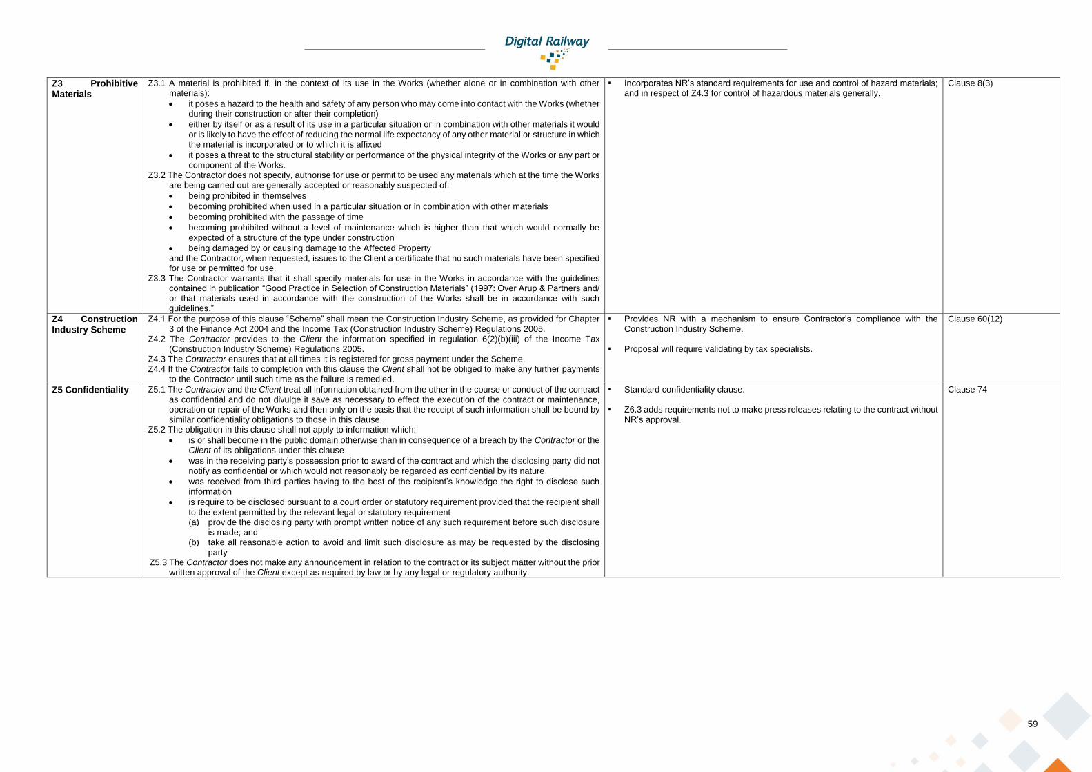
59
Z3 Prohibitive Materials
Z3.1 A material is prohibited if, in the context of its use in the Works (whether alone or in combination with other materials):
• it poses a hazard to the health and safety of any person who may come into contact with the Works (whether during their construction or after their completion)
• either by itself or as a result of its use in a particular situation or in combination with other materials it would or is likely to have the effect of reducing the normal life expectancy of any other material or structure in which the material is incorporated or to which it is affixed
• it poses a threat to the structural stability or performance of the physical integrity of the Works or any part or component of the Works.
Z3.2 The Contractor does not specify, authorise for use or permit to be used any materials which at the time the Works are being carried out are generally accepted or reasonably suspected of:
• being prohibited in themselves
• becoming prohibited when used in a particular situation or in combination with other materials
• becoming prohibited with the passage of time
• becoming prohibited without a level of maintenance which is higher than that which would normally be expected of a structure of the type under construction
• being damaged by or causing damage to the Affected Property and the Contractor, when requested, issues to the Client a certificate that no such materials have been specified for use or permitted for use.
Z3.3 The Contractor warrants that it shall specify materials for use in the Works in accordance with the guidelines contained in publication “Good Practice in Selection of Construction Materials” (1997: Over Arup & Partners and/ or that materials used in accordance with the construction of the Works shall be in accordance with such guidelines.”
▪ Incorporates NR’s standard requirements for use and control of hazard materials; and in respect of Z4.3 for control of hazardous materials generally.
Clause 8(3)
Z4 Construction Industry Scheme
Z4.1 For the purpose of this clause “Scheme” shall mean the Construction Industry Scheme, as provided for Chapter 3 of the Finance Act 2004 and the Income Tax (Construction Industry Scheme) Regulations 2005.
Z4.2 The Contractor provides to the Client the information specified in regulation 6(2)(b)(iii) of the Income Tax (Construction Industry Scheme) Regulations 2005.
Z4.3 The Contractor ensures that at all times it is registered for gross payment under the Scheme. Z4.4 If the Contractor fails to completion with this clause the Client shall not be obliged to make any further payments
to the Contractor until such time as the failure is remedied.
▪ Provides NR with a mechanism to ensure Contractor’s compliance with the Construction Industry Scheme.
▪ Proposal will require validating by tax specialists.
Clause 60(12)
Z5 Confidentiality Z5.1 The Contractor and the Client treat all information obtained from the other in the course or conduct of the contract as confidential and do not divulge it save as necessary to effect the execution of the contract or maintenance, operation or repair of the Works and then only on the basis that the receipt of such information shall be bound by similar confidentiality obligations to those in this clause.
Z5.2 The obligation in this clause shall not apply to information which:
• is or shall become in the public domain otherwise than in consequence of a breach by the Contractor or the Client of its obligations under this clause
• was in the receiving party’s possession prior to award of the contract and which the disclosing party did not notify as confidential or which would not reasonably be regarded as confidential by its nature
• was received from third parties having to the best of the recipient’s knowledge the right to disclose such information
• is require to be disclosed pursuant to a court order or statutory requirement provided that the recipient shall to the extent permitted by the relevant legal or statutory requirement (a) provide the disclosing party with prompt written notice of any such requirement before such disclosure
is made; and (b) take all reasonable action to avoid and limit such disclosure as may be requested by the disclosing
party Z5.3 The Contractor does not make any announcement in relation to the contract or its subject matter without the prior
written approval of the Client except as required by law or by any legal or regulatory authority.
▪ Standard confidentiality clause.
▪ Z6.3 adds requirements not to make press releases relating to the contract without NR’s approval.
Clause 74

60
Z6 Track Access Z6.1 The Contractor submits written notice to the Client confirming any speed restrictions, track possession or isolation requirements in accordance with the Client’s current planning procedures (or as otherwise laid down in the contract) in advance of the proposed commencement of work on or near railway lines.
Z6.2 The Client reserves the right to cancel or alter the dates and times of the agreed speed restrictions, track possessions or isolations at short notice if this proves necessary because of any emergency affecting the safe or uninterrupted running of rail traffic, but in such event the Client makes alternative arrangements as soon as the Client’s programme permits. Such cancellation or change in circumstance shall be a compensation event.
Z6.3 Where any part of the Works has to be carried out during an agreed period of a speed restriction, track possession or isolation, the Contractor shall make adequate arrangements to ensure that such part can commence in accordance with the Accepted Plan, and can be completed as early as possible, and in any case within that period. The arrangements shall include the provision of sufficient and suitable Contractor’s Equipment (including where practicable, standby equipment) and sufficient labour.
Z6.4 Prior to commencement of any speed restriction, track possession or isolation, the Service Manager is of the opinion that the Contractor has failed to comply with the requirements of clause [Z6.3], he may at his discretion cancel the speed restriction, track possession or isolation, or reduce the extent of the work that the Contractor may carry out during such speed restriction, track possession or isolation and the Client notifies the Contractor accordingly.
Z6.5 If, during a speed restriction, track possession or isolation, the Service Manager is of the opinion that the Contractor will be unable to complete the planned work (or any revision proposed by the Contractor) to his satisfaction so as to permit the termination of the speed restriction, track possession or isolation at the time agreed, then the Service Manager may instruct the Contractor to reduce the extent or vary the dates and times of the work to be carried out during such speed restriction, track possession or isolation. Such reduction or variation shall not entitle the Contractor to a compensation event if and to the extent that the Contractor’s inability to complete the planned work was due to a breach by the Contractor of the requirements of the contract.
▪ Establishes NR’s right to amend possessions to the extent this is necessary to ensure uninterrupted operation of the railway.
▪ Actual liability for overruns is set out in clause 34 of NR12(S&T) [see proposed X26 above].
Clause 75; also to be read in conjunction with amended clause 34.
Proposed Bespoke Amendments to Core Clauses
21.2 The Contractor’s design
Add the end of the first sentence add “The Service Manager accepts or rejects the design within the time period set out in the Accepted Plan. If the design is not accepted the Service Manager sets out the reasons for non-acceptance and the changes that in the Service Manager’s opinion are to be made to allow acceptance.”
▪ Confirms that the time scales for acceptance or rejection of designs will be set-out in the Accepted Plan; and that, in order to allow the programme to be maintained, the reasons for any nor acceptance will be stated.
Clause 7
24.2 Working with the Client and Others
Delete the second sentence beginning “Any cost incurred…”. ▪ Typically, LDs would apply for delay, as it will not normally be possible for the Contractor to manage Others. Incentivisation provisions and integration meetings would typically be implemented to ensure collaborative working practices and mitigation of costs.
Clause 47
27 Assignment Add a new 27.2 to read: “27.2 The Client shall be entitled to assign, charge or transfer the contract with the Contractor’s prior written agreement (which shall not be unreasonably withheld or delayed).”
▪ Adds in an additional right for NR to assign or transfer the contract, subject to the agreement of the contract which cannot be unreasonably withheld or delayed.
Clause 3(1)
30.3 Starting and the Service Period
Delete Clause 30.3. ▪ This standard NEC clause appears designed around building/ property management. Management and operation of the Affected Property would be outside of the scope of these works.
60.1(15) Compensation Events
Propose that Cl.60.1(15) is amended to read: (15) A change in the law of the country in which the Affected Property is located or a change in Rail Group Standards,
Network Rail Standards or other equivalent standards which occurs after the Contract Date.
▪ Provides a mechanism for early warning and assessment of changes in applicable railway standards; which can be expected to change many time through the life of the project.
Clause 8(1)
60.1(21) Compensation Events
Add a new Para (21) to read: (21) The Contractor encounters physical conditions which
• are within the Site
• are not weather conditions, and
• an experienced contractor would have judged at the Contract Date to have such a small chance of occurring that it would have been unreasonable to allow for them.
Only the difference between the physical conditions encountered and those for which it would have been reasonable to have allowed for is taken into account in assessing a compensation event.
▪ The comparative clause within NR12(S&T) is clause 12. However, to keep to NEC principles the proposed clause is the standard NEC 4 Clause 60.1(12) wording.
▪ Given the nature and duration of the services it is proposed that this would be a practical level of test process for assessing the impact of unforeseen site conditions.
Clause 12
60.1(22) Compensation Events
Add a new Para (21) to read: (22) A weather measurement is recorded before the Completion Date for the whole of the works which would make it impracticable or unsafe to Provide the Services in accordance with the Accepted Plan.
▪ The comparative NR12(S&T) clause entitles a change in respect ‘exceptional adverse weather conditions’.
▪ We recommend clarifying this to refer to weather conditions which would make it impracticable or unsafe for the works to be provided in accordance with the Accepted Plan.
▪ Given the nature and duration of the services it is proposed that such
circumstances should trigger an assessment of safety and programme mitigation measures.
Clause 44(1)(c)
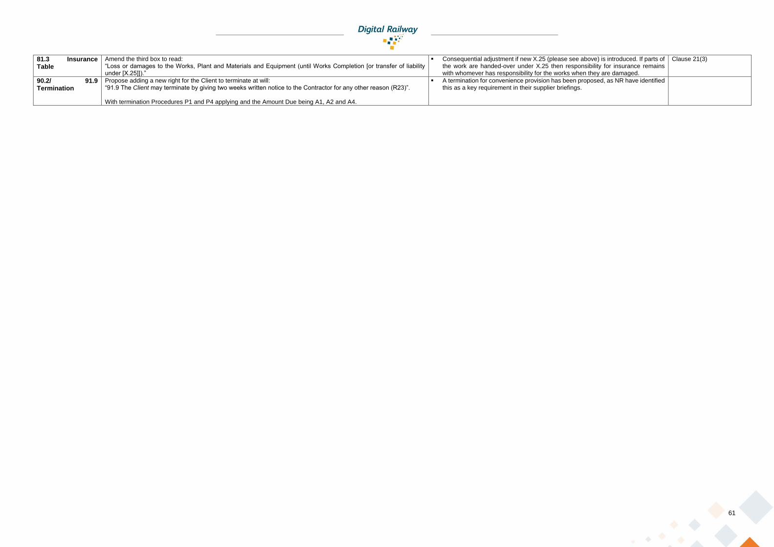
61
81.3 Insurance Table
Amend the third box to read: “Loss or damages to the Works, Plant and Materials and Equipment (until Works Completion [or transfer of liability under [X.25]]).”
▪ Consequential adjustment if new X.25 (please see above) is introduced. If parts of the work are handed-over under X.25 then responsibility for insurance remains with whomever has responsibility for the works when they are damaged.
Clause 21(3)
90.2/ 91.9 Termination
Propose adding a new right for the Client to terminate at will: “91.9 The Client may terminate by giving two weeks written notice to the Contractor for any other reason (R23)”. With termination Procedures P1 and P4 applying and the Amount Due being A1, A2 and A4.
▪ A termination for convenience provision has been proposed, as NR have identified this as a key requirement in their supplier briefings.

62
Proposed Adjustments to the Contract Data Part One
The following additions to the Contract Data Part One are proposed where the corresponding draft clause mentioned above is adopted. In each instance the information provided is the same a currently specified in the NR12(S&T) conditions.
X24: Client’s Options
The Client’s Options are: Option to be exercised no later than:
1. [Option 1] [Date 1]
2. [Option 2] [Date 2]
3. [Option 3] [Date 3]
X25: Additional Responsibility for Care of the Works
The works for which X25 applies are:
1. [Insert Item Definition]
2. [Insert Item Definition]
3. [Insert Item Definition]
4. [Insert Item Definition]
X26: Liability for Railway Costs
For the first 60 minutes or part thereof £[Insert] per minute
For the next 15 minutes or part thereof £[Insert] per minute
For the next 15 minutes or part thereof £[Insert] per minute
For the next 15 minutes or part thereof £[Insert] per minute
For the next 15 minutes or part thereof £[Insert] per minute
For subsequent delay £[Insert] per minute
The Contractor’s total liability for Railway Costs is limited to [£based of 15% of the Prices]
X27: Works performed under previous purchase orders
The purchase orders to which X27 applies are:
1. [Insert PO Number] dated [Insert date]
2. [Insert PO Number] dated [Insert date]
Z2 CDM Regulations
The CDM Co-ordinator is:
Name: [Network Rail Infrastructure Limited]
Address: [Insert Address]