digital mechanical design - phcp pros€¦ · 14 designer’s guide: ... design#26 instant hot...
TRANSCRIPT

DigitalMechanicalDesign
Inside this issue• CAD Solutions: Finding the Right Fit
• BIM is Not Just 3D Modeling
• Batteries of Solar Thermal Energy
• Rooftop Drainage Systems
• CSST System Advancements
See page 33
pe09_pgs_01_03:Layout 1 8/27/10 9:37 AM Page 1

G U A R A N T E E D F O R L I F E
LEARN MORE:www.webstonevalves.com
Tel: (800) 225-9529
SECONDARY CIRCUIT LOOP APPLICATION
Two Hydro-Core Manifolds (Flange Left) utilized in a Secondary
Circuit Loop application
NEAR-BOILER PIPINGFloor Style Mod/Con Boiler w/
Hydro-Core Manifold (Flange Right)
THE CORE OF ANY PROFESSIONAL
BOILER INSTALLATION
The Hydrocore is a fully fabricated forged brass manifold designed specifi cally for hydraulic separation, pump isolation, and purging in near boiler piping or secondary circuit loop applications.
Guaranteed to save you time, space, and leak paths - Hydro-Core is the Only Way to Install a Boiler.
FEATURES• Precisely crafted closely
spaced tees for hydraulic separation
• Webstone Isolator® w/ Rotating Flange & Drain (Left or Right Sided Flange Orientations)
• Webstone Ball Drain™
• Union Connection w/ 1⁄4" NPT Gauge Port (Plugged)
• Custom fabricated boiler-specifi c supply and return lines available
BENEFITS• Fewer Leak Paths
• Eliminates 18 Connections
• Saves Space and Labor
• Easily purge and descale the boiler
PATENTS PENDING
BOILER
Circle 1 on Reader Reply form on page 57
pe09_pgs_01_03:Layout 1 8/27/10 9:29 AM Page 2

TM
Circle 2 on Reader Reply Form on page 57
pe09_pgs_01_03:Layout 1 8/27/10 9:29 AM Page 3

COLUMNS
Page 4/Plumbing Engineer September 2010
Volume 38, Number 9, September 2010
FEATURES
������������������������������������� �#�������� ������������������� ��������#����������� ��������������#���������������������������������"#� �����������������"�����#�������"�������!���������
See ad on page 33
INSIDE THIS ISSUE
INDUSTRY NEWS &OTHER DEPARTMENTS
8 | ICC signs MOU with U.K. asso-ciation to advance plumbingexpertise
8 | B&G’S Little Red Schoolhouseannounces fourth quarter schedule
8 | Plumbing category added to AHR Expo® Innovation Awards
10 | HydrationStation™ GreenSpeclisted
10 | Danfoss president addressesenergy efficiency during CleanEnergy Ministerial
12 | Franklin Electric adds mobilefacility
56 | IAPMO encourages ‘Green’
58 | Trimble acquires Accubid assets
54-55 | NEW PRODUCTS
57 | AD INDEX
58 | CLASSIFIEDS
58 | MOVERS
6 Editor’s Letter: To BIM or not to BIM14 Designer’s Guide: Heuristics and social captivity18 Code Classroom: Design & Installation Pitfalls – Part 224 FPE Corner: A difficult decision28 Solar Solutions: Design#26 Instant hot water recirculation —
innocuous energy thief
Rainwater Roof Drainage SystemsSort out the many considerations in the design ofstorm/rainwater systems.
Story on page 48
Finding the Right FitWith all of the CAD solutions on the market, how do you pickthe right option for you?
Story on page 32
BIM is Not Just 3D ModelingWe are moving into an area where liability is shifting fromthe contractor to the engineer, and the engineer may notsee it coming.
Story on page 36
Batteries of Solar Thermal EnergySpec’ing storage tanks for solar domestic hot water sytems.
Story on page 44
CSST System Advancements Take Aim at Lightning SafetyWhen using flexible gas piping or corrugated stainless steeltubing (CSST), it is essential to understand that properinstallation is critical to ensure the most protection from theeffects of lightning, which can potentially damage metallicsystems. Story on page 52
The PHC industry is on the forefrontof computer designs; open your eyesto the breadth of offerings.
Cover courtesy of Autodesk
pe09_pgs_04_05.qxd:Layout 1 8/27/10 9:35 AM Page 4

Circle 3 on Reader Reply form on page 57
pe09_pgs_04_05.qxd:Layout 1 8/27/10 9:35 AM Page 5

That’s a silly question, really. In the January 2010 issue of PlumbingEngineer, we explored the topic of Building Information Modeling, orBIM, and its many favorable attributes. There is no denying that BIM con-
tinues to help designers draw better specs, and it streamlines efficiency. In thatissue, contributing writer Eric Winslow, Superior Air Handling in Clearfield,
Utah, stated, “While CAD tech-nology, including 3D modelingand the idea of utilizing embed-ded information from withinthe 3D model is certainly notnew to the HVAC industry,BIM is now being applied to allbuilding trades. It is now possi-ble to create a virtual re-cre-ation of the project includingall necessary components fromthe structural steel skeleton allthe way down to the fixturesand finishes. These compo-
nents are united into a single integrated model for analysis. Many of the objectsare rich in embedded information, which serves a multitude of purposes, whilecurrent trends in BIM implementation see 4D, 5D and XD technologies.”
Moreover, most PHC manufacturers offer some sort of CAD/BIM offering tohelp end users better implement specific products. But it is important to under-stand software designs, and CAD and BIM technology. In this issue, KateMorrical, technical marketing manager for Autodesk, offers up the uniqueadvantages of CAD software in Finding the Right Fit, page 32. “Clients andother project stakeholders expect your designs to be digital and compatiblewith the best-in-class design software they are using,” says Morrical. Makesure you are on the cutting edge of design software. The sky’s the limit, right?
Well, on the other hand, we get a unique perspective from Peter Kraut in hisoffering, BIM Is Not Just 3D Modeling, page 36. Here, Kraut tells us thatalthough BIM has its great advantages, be cognizant of all aspects of computerdesign modeling.
“Most future engineers graduating just a few years ago have never modeled in3D... The problem with BIM is that we are now asking one of the least experi-enced designers to make major engineering decisions.”
Kraut continues, “As engineers are adding layers of information to theirdrawings, the time required for design is increasing. And, as the burden of coor-dination has shifted toward the company producing construction documents,something has to give. The burden of liability and other responsibilities areshifting as well. BIM raises the bar and takes 3D modeling to a higher level. Justmake sure you understand the difference.”
The power, literally, is at your fingertips. It’s up to you to keep your eyesopen. n
Editorial, Advertising,Production, Accounting and
Administrative Offices
1838 Techny Ct.Northbrook, IL 60062
(847) 564-1127 • Fax: (847) 564-1264E-mail: [email protected]
OwnerTom M. Brown
Editorial & Production StaffJohn Mesenbrink, Editorial DirectorMarilyn Cunningham, Associate EditorCate C. Brown, Production ManagerMark Bruno, Art Director/Prepress
ContributorsTimothy Allinson, P.E., Designer’s Guide
Sam Dannaway, Fire ProtectionRon George, CPD, Code UpdateDan Holohan, Heating Help
Bob “Hot Rod” Rohr, Green SystemsBristol Stickney, Solar Solutions
Sales StaffBrad Burnside, Publisher East1838 Techny Court, Northbrook, IL60062 Phone: 847/564-1127 Cell: 224/659-3984Fax: 847/564-1264E-mail: [email protected]
David Schulte Midwest, South and E. Canada1838 Techny Court, Northbrook, IL 60062Phone: 847/564-1127 Cell: 847/420-4686Fax: 847/564-1264E-mail: [email protected]
Diane Spangler West, Texas and W. CanadaPO Box 9802, Fountain Valley, CA92728 Phone: 714/839-6700Fax: 714/839-6777E-mail: [email protected]
To BIM or not to BIM?
Editor’s Letter
Page 6/Plumbing Engineer September 2010
PLUMBING ENGINEER(USPS 567-950) ISSN 0192-1711
PLUMBING ENGINEER (USPS 567-950) ISSN 0192-1711 is published monthly by TMB Publishing Inc., 1838 TechnyCourt, Northbrook, IL 60062. Phone (847) 564-1127, Fax (847) 564-1264. Magazine is free to those who design and spec-ify plumbing/piping systems in commercial, industrial, institutional and governmental buildings; as well as government offi-cials and plumbing inspectors. Subscription rates for U.S. and Canada: $50 for one year, $90 for two years. Other coun-tries: $300 per year. Periodical postage paid at Northbrook, IL, and additional mailing offices. POSTMASTER: Change ofaddress should be sent to Plumbing Engineer, 440 Quadrangle Dr., Suite E., Bolingbrook, IL 60440. Material and opin-ions contained in contributed articles are the responsibility of the authors, not of TMB Publishing Inc., Plumbing Engineermagazine or its Editorial Advisory Board. The publisher cannot assume responsibility for any claims made by advertisers.Copyright © 2010 TMB Publishing Inc. All rights reserved. Volume 38, Number 9. Plumbing Engineer is microfilmed byUniversity Microfilms, Ann Arbor, MI, and indexed by Engineering Index Inc. Publications Mail Agreement No. 41499518.Return Undeliverable Canadian Addresses to PO Box 503, RPO West Beaver Creek, Richmond Hill ON L4B 4R6
John [email protected]
pe09_pgs_06_07rev:Layout 1 8/27/10 10:07 AM Page 6

Something’s happening here
Leonard’s New Building Management System Interface Knows
Because you need real-time, accurate temperature monitoring to know whensomething is amiss…integrating Leonard’s newBuilding Management SystemInterface gives you everythingyou need. Providing you exactlywhat you want: real-timemonitoring of outputtemperature.
Through the use of an Ethernetconnection with integratedbuilding management software,BMSI gives real-time, accuratereadings to monitor temperedwater to the domestic hot watersystem. Integrate BMSI withinstalled mixing valves orintegrate with a complete watertemperature control system, for significant cost savings.
• Interface with buildingmanagement system
• Constant, real-time monitoringof output water temperature
• Simplifies maintenanceprotocol
• MODBUS TCP/IP protocol• Digital display
Leonard’s valves give “integratedcontrol” for all water temperingdesign needs. Before your next project, be sure to visitwww.leonardvalve.com or callour free technical support hotlineat 888-797-4456.
Integrated control with everyvalve from the leader intemperature valves, Leonard Valve.
NEW
Visit us at ASPE!Booth 1101
Leonard...the right mix.
Circle 4 on Reader Reply Form on page 57
pe09_pgs_06_07rev:Layout 1 8/27/10 10:07 AM Page 7

Page 8/Plumbing Engineer September 2010
Industry News
lonDon — the International Code Council (ICC) hassigned a Memorandum of Understanding (MoU) withthe Association of plumbing & Heating Contractors ofengland and Wales (ApHC). the MoU calls for bothorganizations to work together to advance the plumbingindustry overall, including myriad mutual goals on local,national and global levels.
this union will serve to share ApHC and the CodeCouncil’s respective and combined expertise to helpplumbing professionals to advance their trade througheducation about new techniques and technologies.Another key goal outlined in the MoU is to dramatical-ly enhance perceptions among consumers and business-es of the important role that the plumbing industry plays
ICC signs MOU with U.K. association to advance plumbing expertise
More Industry News on page 10
in providing proper sanitation to communities through-
out their respective countries. While access to proper sanitation isn’t an issue in
either of these well developed nations, an additional key
focus of both organizations is to join forces towards
advancing proper sanitation efforts to assist the 2.6 bil-
lion people who do not currently have access to proper
sanitation.“plumbing is one of the most important industries in
the world. Good plumbing saves countless lives every
single day. people working in the industry are rightly
proud of what they do,” said Clive Dicken, chief execu-
tive officer of ApHC. “However, we face two issues:
firstly, in the developed world, people have become
complacent about sanitation and how their health
depends on it; secondly, many parts of the developing
world still do not have the luxury of decent sanitation,
and 4,000 children die each day because of this.”
the ApHC and Code Council will collaborate on
efforts independent of and alongside other sanitation-
related organizations to advance global sanitation stan-
dards. one example of how the Code Council is already
sharing their knowledge towards this goal is their exten-
sive work serving on the committee that is developing
the Global Guidelines for proper toilet Design. Working
collaboratively with the World toilet organization
(Wto) and other global sanitation organizations that
focus on the global sanitation crisis, this document will
serve to standardize the design, installation and mainte-
nance of toilets throughout the world, making it easier
for less developed nations to adopt and enforce these
code provisions.
• Steam System Design & Application December 6 – 8
• Modern Hydronics Advanced Seminar December 13 –15
For information, visit www.schoolhouse.itt.com.
Plumbing category added to AHR Expo® Innovation Awards
WeStport, Conn. — reflecting its growing presence atthe industry’s leading HvAC/r event, “plumbing” hasbeen added as a new category to the 2011 AHr expoInnovation Awards. Widely acclaimed as one of the mostprestigious honors in the HvAC/r industry, theInnovation Awards recognize the most innovative anduseful products among the thousands on display at theAHr expo (www.ahrexpo.com). About 150 entries sub-mitted by exhibitors each year are judged on the basis ofdesign, unique performance, market impact and value tothe HvAC/r industry.
now in their ninth year, the Awards are also meant to
B&G’s Little Red Schoolhouse announces fourthquarter schedule
Morton Grove, Ill. — Bell & Gossett, a leader in edu-cation for the hydronic heating and plumbing industries,has announced its training course schedule for the fourthquarter of 2010. the free training seminars are offered atthe Bell & Gossett little red Schoolhouse educationCenter in Morton Grove, Illinois, a suburb of Chicago andare open to engineers, contractors and facility mainte-nance professionals.
the seminars are tailored to various industry occupa-tions and cover a wide range of important topics. the leadseminar instructor is leeD certified for all programs.Upon completion of the three-day seminars, CeU creditsare awarded to graduates.
the fourth quarter Schoolhouse seminars include:• Modern Hydronics Basic Seminar, october 4 – 6• Steam System operation & Maintenance
october 11–13• Design & Application Seminar november 1–3• large Chilled Water Design Seminar november
15 –17
Signing the MOU in London are APHC CEO Clive Dicken(l) and Jay Peters, ICC’s PMG group executive director.
pe09_pgs_08_13_58rev:Layout 1 8/26/10 9:47 AM Page 8

www.symmons.comCopyright © 2010 Symmons Industries, Inc., Braintree, Massachusetts
From hotels to hospitals, from schools to stadiums,
Symmons products have been trusted by
professionals for 70 years.
FOR COMMERCIAL PROJECTSTHE SOLUTION IS SYMMONS®
Circle 5 on Reader Reply Form on page 57
pe09_pgs_08_13_58rev:Layout 1 8/26/10 9:47 AM Page 9
Industry News
Page 10/Plumbing Engineer September 2010
promote and encourage new product development in tenmajor categories:
• Building Automation• Cooling• Green Building• Heating• Indoor Air Quality (IAQ)• Refrigeration• Software• Tools, Instruments• Ventilation• Plumbing“Plumbing products, technologies and solutions have
had a growing presence at AHR Expo for several years,”said Clay Stevens, president of International ExpositionCompany, which produces and manages the AHR Expo.“Adding plumbing as a new category to the AHR ExpoInnovation Awards allows us to include all the major seg-ments represented at the show.”
Entries for the 2011 awards are due September 15,2010.
HydrationStation™ GreenSpec listed
SPARkS, NEV. — Haws® Corporation announced the recentGreenSpec listing of their revolutionary water delivery
system, the HydrationStation.GreenSpec is an exclusiveonline directory of environ-mentally friendly products.GreenSpec researches andevaluates qualifying productsbased on how the productaddresses key environmentalissues and specific criteria.The HydrationStation wasassessed under a wide rangeof environmental qualitiesand was listed as an innova-tive product because it allowsusers to reduce their depen-dency on single-use plasticwater bottles. On average, theHydrationStation saves morethan 37,800 16.9 oz. single-use plastic water bottles a yearfrom entering landfills.
The HydrationStation has received various accoladesfrom sustainability groups across North America. Theproduct has been on the market for over a year and hasbeen installed in a variety of applications from universitiesto ski resorts, including the School of the Art Institute ofChicago, Zuda Yoga of Sacramento, City of RanchoCucamonga, Monarch Mountain Ski Resort in Coloradoand more.
Casey Hayes, Haws Corporation’s director of engi-neered solutions, presented a workshop titled ANSIZ358.1-2009 Emergency Eyewash/Showers — TepidWater in the Workplace at the Voluntary ProtectionPrograms Participants’ Association Conference in August.The presentation included information about the newlyupdated Z358.1-2009 standard, studies on tepid water andsolutions for market needs.
Hayes has been with Haws for more than 20 years andhas served on a wide variety of industry standard devel-opment committees, as well as having authored severalhundred trade press articles and papers over the past tenyears. As director of engineered solutions he organizes acomplete line of custom engineered mixing valves, tem-pered water solutions, recirculation systems, air-chargedsystems and alarms and has a wide-breath of knowledgeand experience with ANSI Standards.
To learn more about the HydrationStation, visitwww.stayhydrated.net.
Danfoss president addresses energy efficiency during Clean Energy Ministerial
BAlTIMORE — On July 19, Robert Wilkins, president ofDanfoss North America, one of the world’s leading manu-facturers of high efficiency electronic and mechanicalcomponents and controls for air-conditioning, heating,refrigeration and motion systems, joined other industryleaders in discussions on renewable energy, energy effi-ciency, smart buildings and smart grid technologies duringthe Clean Energy Ministerial in Washington, D.C.
Hosted by the American Council On Renewable Energy(ACORE), the Alliance to Save Energy (ASE) and theU.S. Green Building Council (USGBC), the StakeholderMeeting prefaced the Clean Energy Ministerial and
Hayes
More Industry News on page 12
Continued from page 8
Circle 6 on Reader Reply Form on page 57
pe09_pgs_08_13_58rev:Layout 1 8/26/10 9:47 AM Page 10

Circle 7 on Reader Reply Form on page 57
pe09_pgs_08_13_58rev:Layout 1 8/26/10 9:48 AM Page 11

Circle 8 on Reader Reply Form on page 57
Specifically, we need tax incentives for replacing old,inefficient equipment. We need stronger building codesthat are enforced. We need an effective building ratingsystem to ensure investment in energy savings leads toincreased building values.”
Franklin Electric adds mobile facility
BlUFFTon, InD. —Franklin Electricannounced the addi-tion of a mobile train-ing facility to its tech-nical toolbox of ser-vice and trainingoptions, providingmobile, hands-on cus-tomer support opportunities to the water systems industry.
This new mobile training facility is the latest tool addedto Franklin’s already extensive training portfolio, whichincludes FranklinTECH factory training, on-the-road sem-inars, field service support and a technical service hotline.The facility focuses on two major product areas: drives forconstant pressure apps and sump, sewage and effluent
Continued on page 56
included morethan 150 cleanenergy leadersfrom technologycompanies, finan-cial services, pro-fessional ser-vices, academia,associations, non-profits and more,to discuss thepolicies andmechanisms nec-essary for theacceleration ofworldwide cleanenergy deploy-ment.
Wilkins, who addressed energy efficiency in end-usesectors alongside representatives from SustainableDevelopment Capital, Whirlpool, and Wal-Mart, calledfor action, saying, “Forty percent of all energy consump-tion in the U.S. is related to buildings. The built environ-ment is divided between new construction and existingbuildings. Each group has unique challenges and con-straints, but both groups require strong energy policy.
Robert Wilkins (far right), president ofDanfoss North America, joined otherclean energy leaders during the first-everClean Energy Ministerial StakeholderMeeting to discuss policies and mecha-nisms necessary for the acceleration ofworldwide clean energy deployment.
Page 12/Plumbing Engineer September 2010
Industry NewsContinued from page 10
(< 250 ºF)Tru-Balance 2550FS 25/50 Rated Rigid Foam Insulated Saddles
(> 300 ºF)Tru-Balance 1200E Calcium Silicate Insulated Saddles
2550FS 25/50 Rated Rigid Foam Inserts with
1200E Calcium Silicate Inserts with
Roundup Round Cornered Saddles
White Roundup Saddles Wraparoo Hanger Cover System
pe09_pgs_08_13_58rev:Layout 1 8/26/10 9:48 AM Page 12

Circle 9 on Reader Reply Form on page 57
pe09_pgs_08_13_58rev:Layout 1 8/26/10 9:48 AM Page 13

Page 14/Plumbing Engineer September 2010
Recently I read a great editorial on ENR.com by agentleman named Jon Schmidt, P.E., a structuralengineer in Kansas City, entitled Don’t Blame
Engineering. It focused on the Gulf oil spill, and the ten-dency to blame engineering for such a crisis, whereas thefault often lies more with management.
Engineering has a certain “social captivity” that pro-duces market-driven value judgments rather than purelytechnical solutions to engineering challenges. When theboundary limits of engineering are stretched, the interestsof an employer, client or government might drive the man-agerial-level decision making process more so than thetechnology. State-of-the-art heuristics are often temperedby social captivity in deriving engineering solutions.
“Roughly speaking,” Schmidt wrote, “a heuristic is anyplausible aid or direction in solving a problem that is, inthe final analysis, unjustified, incapable of justificationand potentially fallible.” Hunter’s Curve is an example ofa heuristic. While it cannot be proven absolutely, its basisis practically derived and it has been used successfully formany, many years. However, one has to use Hunter’sCurve discreetly. You would not use it, for example, for asports arena, because the assumed diversities of the curvedo not apply to halftime in a stadium, when your diversi-ty is nearly 100%. “After all,” Schmidt continued, “engi-neering is not deterministic; it routinely involves selectinga way forward from among multiple options when there isno one ‘right’ answer.”
Heuristics generally draw a line in the sand that shouldnot be crossed, and crossing that line can lead to failure.Social captivity can work to push that line further. If theline is pushed and no failure occurs, the heuristic is rede-fined to a new limit point. Social captivity will continueto push the limits of the heuristic until a failure occurs,and then we know where the line truly belonged – aheadof the failure. It was the social captivity that caused thefailure, in an effort to save time or money or both — notthe engineering.
This is why most engineers dislike the concept of valueengineering. It is a form of social captivity that strives todetermine the extent to which the engineer’s design can becompromised in order to save money. Value engineeringwas the reason the Deepwater Horizon failed, althoughcalling it value engineering is akin to putting lipstick on apig. Cheating would be a better reference. Negligencewould fit even better. I am sure it was not the engineerswho made the decisions that compromised the design, buttheir non-technical managers looking to save money,boost profits and increase their bonuses.
The counterargument that supports the concept of socialcaptivity is unfortunately created by the engineering com-munity itself. Too many engineers are guilty of putting toomuch fat into their designs, either because of insecurity, orbecause of an addiction to the concept that “more is better.”As an old colleague of mine once said about domestic hotwater, “I’ve never heard anyone complain about having too
much hot water, but they sure make a lot of noise when theyrun out.” While this is true, it doesn’t mean that you wouldbe justified in specifying a 120-gallon water heater for a 3-bedroom, 2-bath spec home.
The other day I was asked by a client to investigateproblems they were having with their domestic waterpumps. A site visit quickly revealed that the controls forthe pumps were a mess, but I also had to determine if theexisting pumps were properly sized. A first pass at sizingthe pumps revealed that the set should be rated for about
400 gpm and 400 feet TDH. I selected a triplex VFD pack-age with each pump rated for 200 gpm, 400' TDH, and 30HP. This selection allows for one pump to be taken out ofservice (i.e., n+1), which is a prudent design for anupscale high-rise office building.
After sizing the pumping station myself I looked at thepump schedule to assess the existing pumps. To my horrorI found that the existing pumps had a 20 HP lead pumprated for 60 gpm and 540', plus two lag pumps with 60 HP,290 gpm and 540'. That’s 140 HP of pump capacity vs. 90HP. Clearly some value engineering would have been war-ranted in this case.
Engineers need to trust the heuristics, trust the Code, trustthe numbers that they generate, and not add factors of safe-ty and wild assumptions over and above the Code andheuristics. Certainly it is reasonable to provide an n+1design, as I did above in selecting a triplex pumping plant.But how did the design engineer for the referenced buildingselect pumps with 540' of head rather than 400'? Perhaps hewould have argued, “The street pressure might drop.” Well,if the street pressure dropped from 105 psi to 45 psi, mostof the buildings in the area would be in trouble and it wouldprobably be indicative of a water main break.
Other engineers have said many times, “The Code is aminimum standard.” While there are rare cases where theCode might be inadequate (such as the sports arena exam-ple above), the Code is in fact quite conservative, and toimply that it is a minimum and potentially inadequate isabsurd for all but highly unusual projects.
Even NFPA, the national standard for fire protectionsystems, is conservative by design. While fire protectionsystems are static systems rarely put to the test, theMeridian Plaza fire in Philadelphia of 1991 did just that.After a fire that started on the 22nd floor of the buildingraged up eight unsprinklered floors, it finally was arrested19 hours later on the 30th floor with the operation of just
Heuristics and social captivity
Designer’s GuideTimothy Allinson, P.E., Murray Co., Long Beach, Calif.
Continued on page 16
State-of-the-art heuristics are often tempered by social captivity
in deriving engineering solutions.
pe09_pgs_14_17rev:Layout 1 8/26/10 9:52 AM Page 14

TAP INTO OURRESOURCESIAPMO R&T offers certifi cation to every code and standard you need.
® ®)® ®)
®
Circle 10 on Reader Reply Form on page 57
pe09_pgs_14_17rev:Layout 1 8/26/10 9:52 AM Page 15

10 sprinkler heads. Most hydraulic sprinkler designs foroffice buildings include two to three times that number ofsprinklers in the 1,500-sq.-ft. theoretical fire hazard area.Of course it is good to be conservative where life safetyissues are concerned, but I’ve known engineers and firemarshals who add factors of safety to the requirements ofNFPA, because once again, they viewed it as a minimumstandard.
So on one hand we have companies like BP and manylike them that use social captivity to cut corners despitethe recommendations of their technical staff, and on theother we have engineers who produce designs that aremore complex and expensive than the heuristics wouldrequire. In the middle we have the purist engineers, likethose who engineered the space shuttle, who design on thecutting edge of the heuristics and achieve great things. Buteven the space shuttle fell victim to social captivity whenthe Challenger exploded.
We all remember the images of the Challenger when itbroke apart 73 seconds after takeoff. The engineersinvolved in the design knew that the O-rings were flawedand that launch conditions were too cold, but their con-cerns were stifled by NASA’s organizational culture.NASA managers, it was proved, frequently evaded safetyregulations to maintain launch schedule.
After the disaster President Reagan appointed theRoger’s Commission to investigate the failure. The report
Page 16/Plumbing Engineer September 2010
Designer’s GuideContinued from page 14
The views and opinions expressed in this column are those of the author anddo not reflect those of Plumbing Engineer nor its publisher, TMB Publishing.
Circle 11 on Reader Reply Form on page 57
said in part that “...failures in communication... resulted ina decision to launch 51-L based on incomplete and some-times misleading information, a conflict between engi-neering data and management judgments, and a NASAmanagement structure that permitted internal flight safetyproblems to bypass key Shuttle managers.”
Richard Feynman, one of the Commission’s most presti-gious members, said in the appendix of the report that theestimates of reliability offered by NASA management werewildly unrealistic, differing as much as a thousandfold fromthe estimates of working engineers. “For a successful tech-nology,” he concluded, “reality must take precedence overpublic relations, for nature cannot be fooled.” n
Timothy Allinson is a senior professional engineer withMurray Co., Mechanical Contractors, in Long Beach,Calif. He holds a BsMe from Tufts University and an MBafrom New York University. He is a professional engineerlicensed in both mechanical and fire protection engineeringin various states, and is a Leed accredited professional.allinson is a past-president of aspe, both the New York andOrange County Chapters. He can be reached [email protected].
Precision Hydronic Products Division of JL industries, inc. 6730 NE 79th Court - Portland, OR 97218 Phone:(503) 445-4188 - FAX: (503) 445-4187 ©2009 www.phpinc.us
PrecisionHydronics
PrecisionTM
®
U.S.
GRE
ENBUILDING COUNCIL
USGBC ®
www.phpinc.us
Patent Pending Components
PHP SOLAR PUMPING STATIONSSolar pumping stations manufactured with or without heat exchangerHeat exchanger easily removed for repair, cleaning or replacement
market Contractor friendly/simple installationAvailable with/without pumpsFactory tested & fully warranted
Call for quotation
NEWNEW
Made in the USA.We do not export labor.
OEM inquiries welcome for customized models
pe09_pgs_14_17rev:Layout 1 8/26/10 9:52 AM Page 16

When you’re designing a drainage system, whether it’s a commercial kitchen, resort hotel, or sanitary manufacturing facility, your specifi cation can make all the difference. Every aspect, from surface drainage to piping, can contribute to the optimum design.
At BLÜCHER, we support the pursuit of effi cient and effective specifi cations. That’s why we fabricate all our drainage systems in stainless steel – a conspicuously superior material. BLÜCHER drainage systems combine functional durability and aesthetics to create classically fl awless systems. And because BLÜCHER is now a Watts Water Technologies company, you can specify it with confi dence.
Find drainage systems and all the inspiration you’ll need at BLÜCHERdrains.com.
Drainage by Design
A Watts Water Technologies Company
For more information visit our web site at www.BLUCHERdrains.com
S T A I N L E S S S T E E L D R A I N A G E S Y S T E M S
Circle 12 on Reader Reply Form on page 57
pe09_pgs_14_17rev:Layout 1 8/26/10 9:52 AM Page 17

Ron George, CPDPresident, Ron George Design & Consulting Services
Code Update
22 pitfalls to avoid when designing or installing a combined heating hot water and domestic hot water system — Part II (pitfalls 9-22)
Continued on page 20
Pitfall Number 13: Litigation
If you are not willing to commit to properly maintain-ing the system for the life of the system, don’t design it,don’t install it or don’t request that it be installed.Combined systems require an extensive amount of work
and oversight to make sure someone does not get injured.You must document everything, because when someone isinjured, everyone will be named in the lawsuit.
Pitfall Number 14: Code requirements for thermosta-
tic mixing valves
The 2009 International Plumbing Code (IPC) has thefollowing language dealing with combined systems:
501.2 Water heater as space heater. Where a combina-tion potable water heating and space heating systemrequires water for space heating at temperatures higherthan 140°F (60°C), a master thermostatic mixing valvecomplying with ASSE 1017 shall be provided to limit thewater supplied to the potable hot water distribution systemto a temperature of 140°F (60°C) or less. The potability ofthe water shall be maintained throughout the system.
The 2009 IPC also has the following language address-ing maximum water temperatures for instantaneous waterheaters:
501.6 Water temperature control in piping from tank-less heaters. The temperature of water from tanklesswater heaters shall be a maximum of 140°F (60°C) whenintended for domestic uses. This provision shall not super-
The following is a list of problems or pitfalls (9-22)that I have found over the years that are related tocombined heating hot water and domestic hot water
systems. If you can avoid these pitfalls you will have amuch safer system:
Pitfall Number 9: Cast iron boiler on an open system
Cast iron boilers do not perform well with open systemsbecause of the large quantities of water that introducesoxygen and minerals that cause rust stains, oxidation andfouling of the heating surfaces. This mistake does not takelong to find because of the rust stains that appear in sinks,bathtubs and showers. Cast iron boilers can work well, butthey must have a separate closed loop of boiler water thatis treated with corrosion inhibitors and other boiler chem-icals as needed. The boiler water can then be piped to acoil in a hot water tank or to a heat exchanger to providedomestic hot water.
Pitfall Number 10: No storage tank with copper fin
tube boilers
I have seen installations where someone thought theycould save a few bucks by eliminating the storage tankand using the heating hot water main as the storage tank.This does not work in motels, hotels, apartment buildingsand condos. In facilities like these there needs to be astored volume of water ready for use in a dump load suchas a morning shower period. Copper fin tube boilers aredesigned to raise the temperature of the water only 20 to40 F as the water flows through the boiler. If the waterflows too slowly through the boiler, it will scale up and ifit flows too fast the copper will erode away. These typesof boilers need to have a storage tank for plumbing appli-cations with a dump load. In heating applications, the Btuinput is matched to the heating load calculations, and thesystem works fine.
Pitfall Number 11: No thermal expansion tank
All heating hot water system and domestic hot watersystems must have a thermal expansion tank rated for usein a potable water system, not a hydronic expansion tank.The tank should be sized for a system start-up from ambi-ent to hot. If the system has one boiler and two piping sys-tems with a heat exchanger each piping system shouldhave a thermal expansion tank.
Pitfall Number 12: Scalding injuries and deaths
Many designers, contractors and owners forget thatthere are lives at stake when they design and build thecombined hot water systems. People have been scalded todeath or seriously injured when the systems are notdesigned, installed or maintained properly.
Page 18/Plumbing Engineer September 2010
A combined heating hot water and domestichot water system is a hybrid system
that utilizes a boiler or boilers to heat waterfor heating the building environment,
and it uses boiler water to heat domestic hot water for bathing, washing and cleaninguses. The two systems are often combined
in an effort to reduce the initial cost of installation, but there are a lot
of differences between the two that, if not accounted for, could result
in someone getting seriously injured.
pe09_pgs_18_23rev:Layout 1 8/26/10 9:55 AM Page 18

Circle 13 on Reader Reply Form on page 57
pe09_pgs_18_23rev:Layout 1 8/26/10 9:55 AM Page 19

O
What “separates” us from the competition?Custom, jobsite-specific applications • 1 to 100,000 gallon capacities • “Automatic” What “separates” us from the competition?What “separates” us from the competition?Custom, jobsite-specific applications • 1 to 100,000 gallon capacities • “Automatic” models available
first call for heat in the fall rust, debris, iron oxide andstagnant water would be flushed into the strainers of thecontrol valves and into the domestic water system.
Galvanized steel pipe should never be used on a domes-tic hot water system because domestic hot water is anopen system connected to the city water main, whichintroduces a large quantity of oxygenated water into thesystem. Oxygenated water will cause significant corrosionin ferrous metals such as black steel and galvanized pipe.All components of a combined system should be copper oranother code approved non-ferrous material for domestichot water service if they are in contact with the city watersupply. I often see iron valves installed in these combinedsystems. This is usually the result of a heating contractorinstalling or performing maintenance on the combinedsystem and of the contractor not being familiar with therequirements in the code for all components to beapproved for domestic water use.
Pitfall Number 17: Pumps
When sizing pumps for a combined system there shouldbe two separate systems and one boiler. The hydronic sys-tem should be a closed loop that can use large ductile iron-bodied pumps. The problem with an open system is that,when the large pumps are shut down for six months ormore, the pumps, and all hydronic circuits to heating coilsand baseboard heaters, become dead legs in the piping
sede the requirement for protective shower valves inaccordance with Section 424.3.
Pitfall Number 15: Engineered system
I have seen a value engineering option offered by a con-tractor to combine the domestic hot water system with theheating hot water system. This was not a value to theowner, and it was not engineered. During the evaluationprocess, the owner decided to allow the contractor to com-bine the systems without having the contractor provideengineered drawings. This decision gave the contractorthe ability to use whatever he wanted to use. The ownergot a system that did not work.
Pitfall Number 16: Pipe materials
I have seen a cost cutting option labeled as a value engi-neering option given by a contractor. The option wasaccepted, and the contractor simply eliminated the domes-tic hot water system and changed the hydronic systemfrom black steel to galvanized steel piping. This was in acondominium building that had about 500 condos thatsold in the neighborhood of one million dollars each. Thegalvanized pipe started to rust significantly within twoyears of service and rust stains were significant in all fix-tures. The seasonal dead legs from the heating coilsallowed rust barnacles to form until the first call for heat.When the flow in these dead leg branches resumed on the
Code UpdateContinued from page 18
pe09_pgs_18_23rev:Layout 1 8/26/10 9:55 AM Page 20

It’s a “green,” “clean” world out there. Tougher environmental standards and the rising costs of disposing of grease and grease-laden solids means that conventional interceptors simply aren’t good enough for an increasing number of applications.
Only Separator technology gives you the “Pure Performance” you need to prevent free-floating grease and grease-laden solids from causing serious – and expensive – problems downstream.
Only one company can give you 35 years of Separator experience, 26 varieties and over 200 sizes to choose from: Rockford Separators.
Save time, money and hassles with Pure Performance.
5159 28th Avenue, Rockford, IL 61109 • www.rkfdseparators.com
815.229.5077 • 800.747.5077 • Fax 815.229.5108
Download our White Paper today at
www.rkfdseparators.com
Download our
models availableCustom, jobsite-specific applications • 1 to 100,000 gallon capacities • “Automatic” models available
problem was that the scale also formed on the heatingsurfaces and in the control valves, causing them to fail.Upon inspecting the barrel of the chemicals being inject-ed into the water supply, I noted that there were warninglabels stating that the materials were toxic to humans. Ireported this to the building owner, who had to correct thesituation immediately. This was another case of a heatingcontractor working on a plumbing system and not beingfamiliar with plumbing code requirements. The solutionhe came up with would be a possible option for a hydron-ic system, but in a domestic water system that was a codeviolation.
Pitfall Number 20: Loss of both systems when there is
a problem
When there is a problem with a combined system thatcauses the system to shut down, both the domestic hotwater system and the heating hot water system are out ofservice. If it is a boiler problem or another major problem,the entire building could be without both systems for along period of time.
Pitfall Number 21: Legionellae bacteria
A research report in 1988 authored by Al Steele, whowas the president of the ASPE Research foundation at thetime, recommended storing domestic hot water between
system. This is why there should be a separate closed pip-ing circuit for the heating system piping.
Pitfall Number 18: Corrosion
I have seen large cast iron and ductile iron hydronicpumps that were not approved for domestic water sys-tems installed in combined systems. When such systemsare first turned on in the fall, large slugs of iron oxideladen water are forced into the domestic hot water distri-bution system. This generally results in sinks and bath-tubs filled with orange rusty looking water until the entiresystem gets flushed out significantly. The ferrous materi-als in the combined system typically lead to other prob-lems with plugged strainers on control valves and othercomponents.
Pitfall Number 19: Corrosion inhibitors and other
boiler water treatment chemicals
I visited one building on the East Coast where the com-bined system consisted of eight- inch galvanized waterpipes. The galvanized pipes were corroding to the pointwhere the hot water was very cloudy and orange. Thebuilding maintenance personnel chose to add an injectionpump to inject chemicals into the domestic water mainentering the building to raise the PH of the water and tointentionally build up a layer of scale inside the galva-nized piping to minimize the amount of corrosion. The Continued on page 22
Circle 14 on Reader Reply Form on page 57
pe09_pgs_18_23rev:Layout 1 8/26/10 9:55 AM Page 21
Page 22/Plumbing Engineer September 2010
135 F and 140 F and utilizing a thermostatic mixing valveto mix the hot water down to a safe delivery temperaturebelow 120 F. With a storage temperature of 140 F,Legionellae bacteria will die within 32 minutes.
The Legionellae bacteria cannot survive water temper-atures above 131 F (55 C) for more than five or six hours.The bacteria die instantly at temperatures above 158 F (70C). General protection against the bacteria can beachieved by designing an operating water temperature ofat least 140 F (60 C) or higher. As temperatures increase,so does the risk of scalding. For system water tempera-tures below 140 F (60 C) special provisions are necessaryto allow for cleaning and chemical treatment proceduresfor addressing the Legionellae bacteria in the domestic hotwater system.
A storage temperature of 140 F should be high enoughto protect the water heater from the bacteria, but in opensystems with Legionellae bacteria in the municipal watersupply, the potable hot water system would continually bereseeded with high dosages of water that is potentiallyinfested with Legionellae bacteria. This is another reasonwhy combined systems should have a closed loop for theheating hot water system.
Pitfall Number 22: Leakage of boiler water
When boiler water at a higher temperature than 140 F,(180 to 210 degrees F) leaks through a faulty zone valveor solenoid valve or is allowed to flow by gravity circula-tion through a circulating pump that is de-energized, thereis the potential for overheating the domestic hot water. A
thermostat that controls a solenoid valve or circulatingpumps on the water heater should never be used to controlthe temperature in a domestic hot water system.Thermostats allow too great a temperature variation and
there is potential for leakage and temperature creep. Thebest way to address this is to provide a thermostatic mix-ing valve that conforms to ASSE 1017 on the domestic hotwater line coming from the hot water tank to provide asafe hot water distribution temperature.
If you are considering a combined system, avoidingthese pitfalls should help keep your building warm andprovide the occupants a safe temperature of hot water. Ifyou don’t avoid these pitfalls you could find yourself inhot water.
Another option would be to keep life simple and keepthe systems separate. Then you will not have to worryabout someone coming along later and messing up yoursystem design with system modifications or poor mainte-nance that can create scalding issues. Steer clear of com-bined heating hot water and domestic hot water systemsand you will also steer clear of potential litigation. n
Ron George is president of Ron George Design &Consulting Services. He has served as Chairman of theInternational Residential Plumbing & Mechanical CodeCommittee. To contact Ron, write to him at [email protected].
The views and opinions expressed in this column are those of the author anddo not reflect those of Plumbing Engineer nor its publisher, TMB Publishing.
Code UpdateContinued from page 21
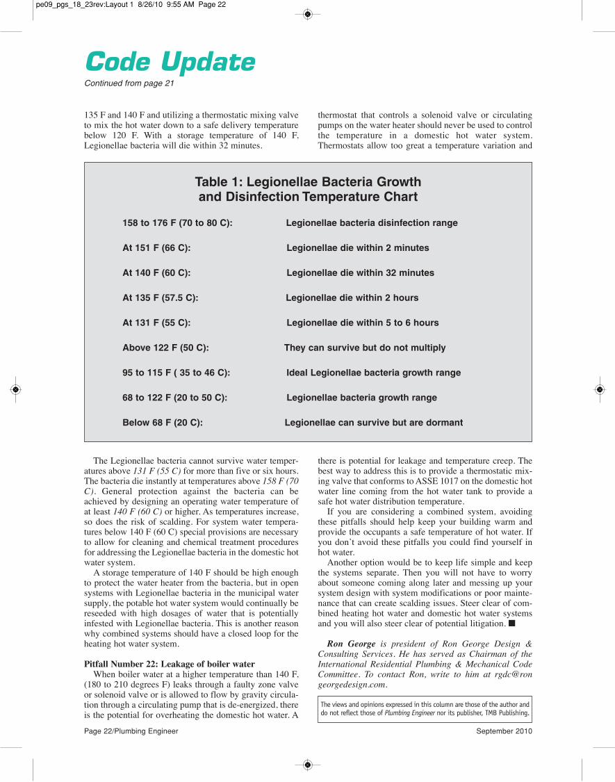
Table 1: Legionellae Bacteria Growth and Disinfection Temperature Chart
158 to 176 F (70 to 80 C): Legionellae bacteria disinfection range
At 151 F (66 C): Legionellae die within 2 minutes
At 140 F (60 C): Legionellae die within 32 minutes
At 135 F (57.5 C): Legionellae die within 2 hours
At 131 F (55 C): Legionellae die within 5 to 6 hours
Above 122 F (50 C): They can survive but do not multiply
95 to 115 F ( 35 to 46 C): Ideal Legionellae bacteria growth range
68 to 122 F (20 to 50 C): Legionellae bacteria growth range
Below 68 F (20 C): Legionellae can survive but are dormant
pe09_pgs_18_23rev:Layout 1 8/26/10 9:55 AM Page 22

Circle 15 on Reader Reply Form on page 57
pe09_pgs_18_23rev:Layout 1 8/26/10 10:32 AM Page 23

Samuel S. Dannaway, PE,President, S.S. Dannaway Associates, Inc., Honolulu
FPE Corner
A difficult decision
Continued on page 26
of being codified in all the model codes, sprinkler protec-tion for one- and two- family homes represents the currentStandard of Care for the industry.
The building official should consider the followinghypothetical:
The building department opts to amend the 2009 I-codes to eliminate the requirement for sprinklers in one-and two-family homes. A few years later there is a firefatality in an unsprinklered home constructed in accor-dance with the building code.
What are the chances that with the help of an akamai(that’s smart in the local Hawaii vernacular) attorney a
family brings a lawsuit both against the jurisdiction andpersonally against the building official? One hopes, forthe building official’s sake, that the political climate is onewhere the mayor does not leave him holding the bag.
Fact or fiction? I believe that time will make this hypo-thetical fiction a fact. Does the building official want to bethe first one forced to go to court to defend the code whenthe fire was in an unsprinklered home constructed subjectto an amended 2009 IRC/IBC?
It is important that those promoting the implementationof the code requirement to sprinkler homes be aware ofthe impact that such a measure can cause and begin tolook at addressing those concerns proactively.
First and most obvious is the impact of the additionalcost of providing sprinkler protection. One way to addressthis issue is to provide tradeoffs in building and zoningcodes that will help to offset the cost. For large subdivi-sions involving many dwelling units, substantial tradeoffscould be implemented to help balance the cost impact.Typical examples from the Home Fire Sprinkler Coalitionwebsite, www.homefiresprinkler.org/index.html, aredescribed as follows:
• Increased distances for fire department turnarounds;• Decreased property line and lot line set backs;• Increased fire hydrant spacing;• Reduced fire flow requirements;• Minimum street width reductions;• Longer dead-ends;• Narrower traffic lanes (substantially reducing the
amount of pavement); • Tee-type turnarounds are permitted, rather than large
In a previous article it was noted that starting with the2009 International Residential Code (IRC) all residen-tial occupancies, including one- and two-family
dwellings, must be provided with sprinkler protection.The adoption of a sprinkler requirement by the 2009 IRCand the apparent confirmation of that requirement in the2012 edition sealed the deal. Now all U.S. model buildingcodes, including NFPA 5000, Building Construction andSafety Code and NFPA 101, The Life Safety Code, areconsistent in their requirement for complete sprinkler pro-tection for all new residential occupancies. (NFPA 101does have provisions that do not require sprinkler protec-tion for certain existing residential occupancies.)
Now many jurisdictions across the country consideringupdating their building codes are faced with a very toughdecision: Do they adopt the code with the requirements forsprinkler systems for one- and two-family homes or dothey amend the building code to eliminate the requirementfor sprinklers for these occupancies? Either choice hassignificant ramifications.
Imagine a city building official trying to make this deci-sion in the midst of the current state of the U.S. housingmarket. Many would agree that adding a requirement forsprinklers is an additional burden that the private sectorsimply should not be subjected to at this time. This cityofficial can expect a heavy lobbying effort, with oppo-nents to the requirement providing all the reasons whysprinklers should not be required. The proponents, usual-ly led by the fire chief, will be in there battling also.
The increased cost and the impact on a struggling hous-ing industry are obvious arguments put forth against ahome sprinkler mandate. However, there is a potentiallegal minefield for government entities to consider.
The problem for the building official is that he or shewill be responsible for this decision, even if it is madewith the help of a committee and even if approved by themayor and city council. For most jurisdictions, it will bethe first time they will be confronted with this type ofdecision. Until recently, the model codes did not uniform-ly require providing home sprinklers. This gave the build-ing official some cover. Under previous codes inHonolulu, for example, builders were allowed the choiceof complying with the 2003 IBC or the 2003 IRC. Bychoosing the IRC one could avoid the sprinkler require-ment altogther.
I understand that many jurisdictions have code amend-ments that allow conditions that are less restrictive thanthe model code. The big difference is that these lessrestrictive provisions have the advantage of legacy. Astime-tested amendments, there is less concern aboutallowing a lower level of safety. The residential sprinklerrequirement, however, is a significant new and stricterpublic safety requirement. Also, in my opinion, by nature
Page 24/Plumbing Engineer September 2010
The increased cost and the impact on a struggling housing industry are obvious
arguments put forth against a home sprinklermandate. However, there is a potential legalminefield for government entities to consider.
pe09_pgs_24_27rev:Layout 1 8/26/10 10:17 AM Page 24

����������$��#"�����!"�"������"�$!���"��$#���"���!�&�#�!����&��#���'�"��������#�������!���$��#�������������!�#����������"�!%�������������#���!��� ����#���"�(�'�$�������$�#��������������$��#"�#�� !�%�����$!����������� �!��!������ !��$�#"�
�������!�#����!����"#� !��$�#�"����#��������$!����$"#!'����������'�#���"#!����"#�&�!!��#��"�����$� �!���������$"#���!�"$ �!#�� �"#����������$!�������) "�� ���� !��!�������&"�'�$�#��!����%���$!���"#� � $��!� !��$�#"�!���#�&����'�$������#����
������'�$���%���$�#� ���!���"��!��$�#� ����$������"��#��!��"���"������"��$#����(����������$��#"����!���!������!��#�����%�"�#����������$��#"������!�����������������
������� ��������������� ������������������������� �� ����� � ��������������������������� � ��
��'��$����������'�!�����
&&&����������$��#"��������������
��'�#����
����������������������� ���������� ��� ���������� ���������������� ������������������������������� ������
� % � �� �� � �� � �
Circle 16 on Reader Reply Form on page 57
pe09_pgs_24_27rev:Layout 1 8/26/10 10:17 AM Page 25
will generate will likely create a lack of qualified contrac-tors and the problems resulting from unqualified installa-tions. Without proper regulation, we can expect solarwater heater contractors to offer sprinkler system installswith their package (OK as long as they are qualified).
Additionally, homeowners will need to be educated onthe care and maintenance of their sprinkler systems. Nolonger will Johnny and Suzy be allowed to play football inthe house.
Regardless of the choice, all involved parties need toapproach the decision with eyes completely open.Eventually, the opposition to sprinklers will fade andsprinklered homes will become commonplace. Until then,the building official has a tough decision.
Samuel S. Dannaway, PE, is a registered fire protectionengineer and mechanical engineer with bachelor’s andmaster’s degrees from the University of MarylandDepartment of Fire Protection Engineering. He is pastpresident and a Fellow of the Society of Fire ProtectionEngineers. He is president of S. S. Dannaway Associates,Inc., a 15-person fire protection engineering firm withoffices in Honolulu and Guam. He can be reached via emailat [email protected].
Circle 17 on Reader Reply Form on page 57
Page 26/Plumbing Engineer September 2010
cul-de-sac turnarounds;• Increased street grades;• Increased densities; and• Longer fire department response times (fewer fire
stations).As noted in previous articles, the sprinkler installation
standard that applies to residential sprinklers for one- andtwo-family dwellings is NFPA 13D, Standard forInstallation of Sprinklers in One and Two-FamilyDwellings and Manufactured Housing. NFPA 13D sys-tems that use the municipal water system for their supplytypically share a connection to the municipal system withthe domestic water service. In many cases, the standardsize water meter provided will have to increase to ¾- or 1-inch in order to accommodate the flows required for thesprinklers. It would be beneficial if sprinkler protectedhomes did not have to pay an additional premium for theincreased water meter size to the Board of Water Supplyor Water Department. In Honolulu, for example, it cost mealmost $2,000 to upgrade the size of my meter.
The authorities responsible also would be wise to takesteps to ensure that contractors installing 13D sprinklersystems are properly licensed and qualified to do so.Requirements pertaining to licensing of contractors per-forming this work must be in place to address this situa-tion. The demand for 13D contractors that the requirement
FPE CornerContinued from page 24
The views and opinions expressed in this column are those of the author anddo not reflect those of Plumbing Engineer nor its publisher, TMB Publishing.
pe09_pgs_24_27rev:Layout 1 8/30/10 11:40 AM Page 26

pe09_pgs_24_27rev:Layout 1 8/26/10 10:17 AM Page 27

Page 28/Plumbing Engineer September 2010
Solar SolutionsBristol Stickney, technical director, Cedar Mountain Solar Systems, Santa Fe, N.M.
Instant domestic hot water (DHW) recirculation hasbeen around for a long time. In buildings where theDHW source is a long way from the hot water fixtures,
a circulator pump is used to force hot water from the waterheater through the hot water supply pipes to the base ofthe fixture and then back to the water heater through a“recirc return” pipe. Originally, this was done mostly forconvenience, so that the user did not have to wait for allthe cold water stranded in the supply pipe to empty itselfdown the drain before the hot water finally arrived.
Over the years, this also became a standard method forsaving water and, for that reason, is required by code inmany locations. In the past it was common practice toinstall a continuous duty circulator and plug it in 24/7. Inrecent years it has become obvious that, using thismethod, water is saved by throwing energy at it (both heatand electricity). So it is worthwhile to rethink this situa-tion by controlling both the waste of energy and the wasteof water.
This issue has come up in nearly every recent solar hotwater installation in which I have been involved. Sooner
or later during the normal operation of a solar hot waterheater, someone will notice that the solar hot water tankdoes not seem to store heat very well. The solar heatseems to disappear from the tank overnight, causing thebackup heater to run in the morning. This is always a sur-prise and a disappointment to the owner or installer sincethe solar storage tank is very well insulated and costs morethan a conventional DHW tank. Rather than “crossingyour fingers” and hoping that this will not happen, it isbetter to forestall the situation by including an upgrade tothe DHW recirc system as part of the solar heating instal-lation. Offering this as an option will at least let your cus-tomers know that you are energy aware and have their bestinterests at heart.
Of course, with a conventional water heater the backupburner must work harder to make up for the heat loss asthe hot water circulates constantly around the building,resulting in higher fuel bills. The electricity consumed bythe circulator and other electrical elements causes fuel tobe burned and water to be consumed at the electric powerplant. In New Mexico, for example, the majority of thatfuel is coal, and the water consumed at the power plant issomething like ¾ of a gallon for every kilowatt hour gen-erated. So the idea that we can save water by throwingelectricity at it is probably mistaken if the electrical con-sumption is not carefully controlled. With this gentlereminder that in the world of energy there is no free lunch,let’s take a look at some of the upgrades that are possiblein a DHW recirculation system to eliminate energy waste.
Piping considerations
In new construction, the hot water supply and recircreturn can be designed to minimize heat loss and maxi-mize pumping efficiency. In a retrofit, sometimes theimprovements are more difficult to install, but shouldalways be seriously considered.
Pipe insulation. Both the hot supply and the recircreturn must be well insulated, especially in locationswhere ground contact or cold air temperatures exist. Ihave seen many installations where the pipe insulation hasbeen forgotten on the recirc return line.
Balanced flow. When a single recirculator is used onseveral parallel loops to various parts of the building, theflows must be balanced just like the loops in a hydronicheating system. Even a well-controlled recirc pump willwaste energy pumping through an unbalanced piping sys-tem as most of the flow will go through the shortest (andhottest) loop. A balance valve placed on the recirc returnpipe under each fixture can be well worth the extra effort.
Multiple circulators. In larger buildings, energy sav-ings may be accomplished by using several different cir-culators instead of a single circulator feeding parallelloops. Both heat and electricity can be saved when eachpump is controlled to provide hot water recirculation onlyto the occupied part of the building.
Control systems
The most common upgrade to any DHW recirc system,new or existing, is electrical controls. Here is a list of typ-ical controls I have added in recent years in order of mostcommon to least common.
Temperature setpoint switch. The easiest and cheap-est way to limit the run-time of the recirc pump is to put asensor on the recirc return pipe that turns the pump offwhen hot water comes back from the building. This can bea snap-disc, a cap-tube or an electronic set point con-
Continued on page 30
Bristol’s Six Principles for Good Solar Hydronic Design
Instant hot water recirculation — innocuous energy thief
The electricity consumed by the circulator and other electrical elements causes fuel to be burned and water to be consumed
at the electric power plant...
...the idea that we can save water by throw-ing electricity at it is probably mistaken if the electrical consumption is not carefully
controlled.
pe09_pgs_28_31rev:Layout 1 8/26/10 10:20 AM Page 28

INTRODUCING THE ACCELERA© 300 HEAT PUMP WATER HEATER:ACCELERATE YOUR SAVINGS!
SAVEENERGYWATERMONEY
The new Accelera® 300 can extract up to 80% of its energy requirements from the air around it. Heat pumps have been around for decades, but a heat pump water heater is a brand new concept. The Accelera® 300 works like an air conditioner - but instead of dumping the heat outdoors, it puts it into the water.
The Accelera’s compressor and fan consume only 1 kWh of electricity to generate the heat equivalent of 3 – 5 kWh. The efficiency of the unit goes up with increasing ambient air temperatures. This ground breaking efficiency redefines what a water heater is capable of, and what savings can really mean !
Energy from nature.
TOLL FREE 800.582.8423www.stiebel-eltron-usa.com
Simply the Best
New!
REDUCES HOT WATER COSTS BY UP TO 80 %
COOLS AND DEHUMIDIFIES THE AIR AROUND IT
LOW STAND-BY LOSSES THROUGH GOOD INSULATION
FEDERAL TAX CREDIT:SAVE 30% UP TO $1,500
OF THE TOTAL SYSTEM COST!
Circle 19 on Reader Reply Form on page 57
pe09_pgs_28_31rev:Layout 1 8/26/10 10:20 AM Page 29

troller. When the return pipe cools off, the pump runs onlyuntil hot water arrives back in the mechanical room andthen pauses until the pipe cools again. For proper controlit is important that the circulation loops be balanced.
Timer switch. It is very common for a timer switch tobe used to allow the recirculation pump to run only duringcritical occupancy hours. The timer switch is often usedalong with the set point control. The biggest drawback ofthe common timer switch is that the clock must be resetafter a power failure.
Manual demand switch. A momentary contact switchthat resembles a door bell button can be placed at each hot
water fixture. This is for users who are energy consciousand don’t mind “asking for instant hot water” by pressingthe button. Both wired and wireless button systems areavailable these days.
Automatic demand switch. An automatic switch suchas an Infrared Red (IR) motion detector or IR beam switchcan be installed near each hot water fixture. This type ofsensor uses a relay to “press the demand button” whenev-er it senses that somebody is nearby. A timer or setpointswitch is used to turn off the circulation after a reasonableamount of time.
The manufacturers of hot water recirculation pumpsnow offer many of these controls and features either builtinto their pumps or as add-on control packages. Some arefairly sophisticated, with sensors and timers built into thepumps and electrical connections for a demand switch. Ifyou haven’t seen this equipment at your local supplier, askthem about it. Good recirc control is just as important fornon-solar as it is for solar water heater systems for peakenergy performance.
Circulator pumps
When modifying these systems, sometimes the existingor originally specified recirc pump will just not do the job.This is most often the case when a continuously circulat-ing system is modified to include a demand switch. In ademand switch system, the circulator only runs for aminute or two. In that short amount of time, the userexpects the hot water to arrive without delay. If there is along pipe run and/or high heat loss (typical of older retro-fits) a larger circulator pump may be needed to provide theflow and pressure necessary to deliver the goods on time.
For example, in a recent retrofit solar heating system, acontinuously circulating Taco 006 bronze pump was mod-ified with demand buttons and a timer relay to minimizeits run-time. The owner reported that it took seven minutesfor the hot water to arrive at the far end of the house. Sinceit was a retrofit situation, with all the piping under a con-crete slab floor, the plumbing and balancing could not be
changed easily. When a Taco 009 bronze pump was sub-stituted the hot water arrived in less than a minute. Sincethe 006 pump originally ran for hours, and the 009 pumpruns only minutes per day, the electrical savings per day issubstantial, and the heat savings in the solar water heatertank is easily evident. A good solar storage tank willindeed provide hot showers in the morning following asunny day if the heat is not pumped out of it all night.
Final notes
At SolarLogic, we are developing integrated methodsof design, installation, control and monitoring for SolarCombi heating systems based on our field experiencefrom recent years. Our goal is not only to assure that aworking system is installed but also that its proper perfor-mance can be monitored, verified and maintained over theyears.
These articles are targeted toward residential and smallcommercial buildings smaller than 10,000 square feet.Brand names, organizations, suppliers and manufacturersare mentioned only to provide examples for illustrationand discussion and do not constitute any recommendationor endorsement. Calculations and estimates are for exam-ple only and are not intended for any particular designapplication.
Special thanks to Dr. Fred Milder for original econom-ic insights included in this article. n
Bristol Stickney has been designing, manufacturing, repair-ing and installing solar hydronic heating systems for more than30 years. He holds a Bachelor of Science in MechanicalEngineering and is a licensed Mechanical Contractor in NewMexico. He is the Chief Technical Officer for SolarLogic LLC inSanta Fe, N.M., where he is involved in development of solarheating control systems and design tools for solar heating pro-fessionals (visit www.solarlogicllc.com for more information.)
Page 30/Plumbing Engineer September 2010
Solar SolutionsContinued from page 28
In this series of articles, I have been making the case
that the key ingredients for solar/hydronic design and
installation can be divided into six categories, listed
below, roughly in order of their importance.
1. RELIABILITY
2. EFFECTIVENESS
3. COMPATIBILITY
4. ELEGANCE
5. SERVICEABILITY
6. EFFICIENCY
The success of any solar hydronic home heating
installation depends on the often-conflicting balance
between any of these six principles. Finding the balance
between them defines the art of solar heating design.
The views and opinions expressed in this column are those of the author anddo not reflect those of Plumbing Engineer nor its publisher, TMB Publishing.
Good recirc control is just as important for non-solar as it is for solar water heater
systems for peak energy performance.
pe09_pgs_28_31rev:Layout 1 8/26/10 10:20 AM Page 30

Circle 20 on Reader Reply Form on page 57
pe09_pgs_28_31rev:Layout 1 8/26/10 10:20 AM Page 31

Page 32/Plumbing Engineer September 2010
Having the right tools for the job is critical to suc-cess. And while you may think that means hav-ing the proper copper fittings, filters, hoses and
pipes, a successful plumbing job actually starts wellbefore you purchase supplies. It starts with design. Butbefore you start your design, there’s another choice tomake: what tools to use? Pencil and graph paper? Thesedays, that won’t get the job done. Clients and other pro-ject stakeholders expect your designs to be digital andcompatible with the best-in-class design software theyare using.
But is it worth it to invest in computer-aided design(CAD) software? Yes. And here’s why.
Move to CAD
The decision to move from hand-drawn plans to CADcan be intimidating—there are a lot of programs tochoose from, the learning curve can be steep and, let’sbe honest, some CAD software can get pretty expensive.However, if you look really closely at the pros and cons,you’ll realize: CAD is the way to go.
• Greater client satisfaction. With a digital represen-tation of your plans, you can more accurately demon-strate your design intent to clients.
• Collaboration. Working with several stakeholders
on a project requires you to communicate in DWG orPDF, a format that is readable and sharable across theentire team; working in these formats means you areable to join that conversation.
• Accuracy and speed. Incorporating technology intoyour design process ensures that you are designing asaccurately and efficiently as possible. Correct measure-ments in your designs mean you order the right type andamount of supplies.
• Reuse. With your designs drafted and saved in adesign program, you can easily reuse drawings to quick-ly complete design projects on time with less wastedmaterials.
• Permitting. A plumbing permit is required for manyjobs, such as altering piping inside a wall or for newinstallations or remodels. To get the permit, often a dia-gram presenting the changes must be submitted alongwith a list of materials — that’s where software comesin. CAD software offers plumbers the ability to switchfrom hand-drawn to accurate, clear and professionallooking diagrams.
Now that you realize moving to CAD software is theright decision for you, how do you chose the right CADprogram for you?
Low investment, high return
Choosing the right software is important, and thereare several factors to consider:
• Financial investment. How much are you willingto spend up front and what will be the cost of your learn-ing curve?
• Skill level. How familiar are you with CAD soft-ware? Do you have some engineering experience thatwould allow you to utilize a more advanced program, orare you new to CAD software and need a simple, easy-to-use program?
• Need. What are your needs, and your client’s needs?Do you need a program that offers simple lines, mea-surements, and DWG compatibility, or do you need amore advanced program that can perform engineeringcalculations?
Whatever the answers to those questions — whether
Continued on page 34
Finding the Right Fit
By Kate Morrical
With all of the CAD solutions on the market, how do you pick the right option for you?
AutoCAD LT 2011 is the ideal tool for creating profession-ally designed documents.
pe09_pgs_32_35rev:Layout 1 8/26/10 10:22 AM Page 32

Superior effi ciency rules the water.
Think about ITT.
Powerful, intelligent and constantly in motion, not just adapting to their surroundings, but dominating them. Like sharks, e-SV pumps are tough, effi cient and built to last. Thanks to a unique combination of new hydraulic design and higher effi ciency motor, the e-SV delivers lower overall life-cycle costs and superior effi ciency compared to
most pumps available today.
• Optimized hydraulic design results in superior boosting performance, effi ciency and NPSHr levels.
• All stainless-steel construction permits NSF certifi cation.
• Expanded line of pump sizes for wide range of applications.
• Patented i-ALERT™ monitor continuously measures vibration to support optimum performance. Available on pumps 10HP and above.
• New design eliminates need to remove motor, reducing repair time by up to 50 percent.
Now there’s more than one way to rule the water.
Find out more at www.goulds.com
• Optimized hydraulic design results in superior boosting performance, effi ciency and NPSHr levels.
• All stainless-steel construction permits NSF certifi cation.
• Expanded line of pump sizes for wide range of applications.
• Patented i-ALERT™ monitor continuously measures vibration to support optimum performance. Available on pumps 10HP and above.
Introducing the Goulds Pumps
e-SVTM Series:energy effi cient, economical and easy-to-install stainless steel multi-stage pumps.
Circle 21 on Reader Reply Form on page 57
pe09_pgs_32_35rev:Layout 1 8/26/10 10:22 AM Page 33

Page 34/Plumbing Engineer September 2010
you’re a newcomer to CAD or an experienced plumbingprofessional looking to update your software, Autodeskhas a product to help you take your business to the nextlevel.
• AutoCAD LT. AutoCAD LT 2011 is the ideal toolfor creating professional design documents. Its exten-sive tool set is more advanced than some other products,and it helps to have some engineering experience, butthe benefits of such robust and flexible software areunparalleled. Use layers and linetypes to organize pipesby size, material, or function. Add symbols and text toyour drawings to fully convey your design intent. Youcan even save your favorite symbols and standard con-tent to easily reuse them in other drawings. AutoCADLT’s genuine DWG file format provides stability andcompatibility to ease communication with clients andcolleagues.
• AutoCAD Freestyle. AutoCAD Freestyle is a sim-ple design tool ideal if you are looking to ease intodesign software. It’s an easy-to-use, low-cost 2D draw-ing software ideal for creating professional-lookingdrawings and plans. Freestyle eases collaborationbecause it produces drawings in the genuine DWG and
PDF, the most common design file format. It has a sim-ple user interface, with just the tools that plumbers needto start drawing right away — no training required. Youcan create accurate, detailed plans to scale with a sim-plified toolset for creating standard shapes, annotatingdrawings, sketching, and inserting images and symbols.The grid on the drawing surface helps set spatial dimen-sions, so you can easily solve problems and create accu-rate sketches. It’s just like drawing on the graph paper
you are used to. To save time, you can select from alibrary of pre-drawn, commonly used symbols — suchas bathroom fixtures.
If you’re looking for even more powerful software,Autodesk also offers AutoCAD, AutoCAD MEP andRevit MEP software with tools for plumbing and pipingdesign, including 3D capabilities and support for build-ing information modeling (BIM). With so many optionsavailable, Take the leap and try CAD software for yourplumbing designs. How far can you take your businesswith the power of software behind you? n
Kate Morrical is technical marketing manager forAutodesk.
AutoCAD Freestyle has a simple user interface, with justthe tools that designers need to start drawing right away —with no training required.
AutoCADContinued from page 32
HIT ITNOW!
plumbingengineer-resource.com
Where plumbing engineers
go for the latest information from manufacturers.
Free information on products, training, and more…
all waiting for you!
Circle 18 on Reader Reply Form on page 57
pe09_pgs_32_35rev:Layout 1 8/26/10 10:22 AM Page 34

Circle 22 on Reader Reply Form on page 57
pe09_pgs_32_35rev:Layout 1 8/26/10 10:22 AM Page 35

Page 36/Plumbing Engineer September 2010
Building information modeling, or BIM, has beenwidely portrayed as 3D modeling. Certainly, a 3Dmodel is the foundation of BIM, but it is so much
more than that. As this technology grows so rapidly, mostdraftsmen have barely scratched the surface of what it iscapable. More unsettling is that the individuals in man-agement who write contracts for BIM don’t understandthe pitfalls associated with it. Sadly, Wikipedia has a bet-ter understanding of BIM than most engineers in ourindustry. Mark my words; in the next 10 years, someonewill lose a fortune from the liabilities inherited in a BIMcontract. This is the future as I see it:
Unused capabilities
BIM software is not only capable of drawing a 3D model,it is capable of engineering it. Revit, for example, comeswith fixture unit values associated with each fixture (see
Image A). These can be edited as needed for each project.The default values are base on the IPC, leaving a little extrawork for those using the UPC. You will need to differentiatebetween private and public use by establishing separate fix-tures for each. Reduced fixture unit values for additionalhose bibs are also rather difficult to manage. All that’s left isto connect your fixtures with a network of piping.
The software then adds fixture units for waste and waterand calculates water flow rates in gallons per minute. Italso can back out the redundant fixture units when a coldwater system feeds a hot water heater. I’m not exactly surehow it calculates a “predominantly flush valve” systemsince this is still an ongoing debate between the local plancheckers and me. Once the software has calculated the
Continued on page 38
Image A
Image B
BIM is NOTjust 3D modelingWe are moving into an area where liability is shifting fromthe contractor to the engineer, and the engineer may notsee it coming. By Peter A. Kraut, P.E., with images and technical
assistance from Walter de la Cruz
pe09_pgs_36_43rev:Layout 1 8/26/10 1:31 PM Page 36

“Cleaner hydronic system water, more comfortable
guests.”
In 2007, the 1929 Masonic Temple was reborn as the Renaissance Providence Hotel. As Steve Beretta tells it, guest complaints about poor air conditioning comfort became frequent and widespread. Taco worked with Steve to troubleshoot the HVAC closed loop system and determined that corrosive iron oxide gunk was fouling the system’s components.
The clear solution.The hotel installed two 4900 Series Air and Dirt Separators to eliminate air microbubbles, sand, dirt and rust in the system. With its patented Pall Ring design, the 4900 Series removes solid particles and air microbubbles
as small as 18 x 10-6m, delivering superior performance that’s tested and certi�ed by Delft Hydraulics. As a bonus, the 4900 saves money, energy, and component wear.
The proof is in hand.“As the quality of the system water improved”, says Steve, “the air conditioning improved.” We’re glad we could help, Steve. That’s why we’re all in business.
Steve BerettaDirector of EngineeringRenaissance Providence Hotel
3:05 PM
Circle 23 on Reader Reply Form on page 57
pe09_pgs_36_43rev:Layout 1 8/26/10 1:31 PM Page 37

Page 38/Plumbing Engineer September 2010
flow rate, it can then size the pipes using the same meth-ods we typically employ. Waste pipe is sized using a fix-ture unit table which can be edited to suit local codes orbuild in a safety cushion for future growth. Water pipe can
be sized using a constant friction loss and velocity limita-tions while maintaining the fixture connector as a mini-mum size (see Image B).
But wait, a check of the pipe sizes in the copper tablereveals that the pipe being modeled is Type K, not Type Las is typically used. Furthermore, Revit converts two fix-ture units to 5 gallons per minute (take another look atImage A). This is different from the Hunter’s Curve con-version with which I am familiar. Combining these twowill yield extremely large pipe sizes. The former can besolved by editing the table of pipe sizes and more careful-ly labeling the “copper” material. The latter is not so easyto solve. It appears that it is embedded in the code andAutodesk is looking into it.
Yet fixture units are just a fraction of the informationcontained in a Revit family. Take for example, a Kohler-Chesapeake lavatory, model K-1724. It can be down-loaded from the manufacturer with length, width andheight as well as pipe sizes and connection locations. Thedefault elevation seems like a good feature to have in aBIM model, but it is left blank for the user to fill in. Thematerial is embedded information and a link to the manu-facturer’s website is included, as well. But what aboutcolor? There is no mention of it, so I assume without a suf-fix, we are modeling the basic white. On the other hand, aa typical pump manufacturer file clearly indicates the fin-
ish as “seafoam green metallic.” Good to know. It alsorecords a 1 horsepower motor at 1,760 rpm, a 7" impellerand a weight of 113 pounds. Hopefully the full 7" impelleris being used, or this may need to be edited before erro-neous information is passed on. To see how much infor-mation is included, take a look at a typical boiler manu-facturer’s boiler (see Image C). The manufacturer haseven included the hardness of the water, although I am notsure how they know where I intend to use it.
What good is all of this information if you can’t accessit quickly? That’s why BIM software allows you to print amaterial take-off from your model. A few keystrokes andyou will find that your model contains one typical boilermanufacturer’s boiler, one typical pump manufacturer’spump, 32 lavatories (in white) of a typical fixture manu-facturer, 647'-83/32" of ¾" Type K copper pipe, (74) ¾"Type K copper 90 degree fittings … and more. Interesting,
Continued on page 40
Image C
Image D
BIMContinued from page 36
pe09_pgs_36_43rev:Layout 1 8/26/10 1:31 PM Page 38

Circle 24 on Reader Reply Form on page 57
pe09_pgs_36_43rev:Layout 1 8/26/10 1:31 PM Page 39

Page 40/Plumbing Engineer September 2010
ness coefficient and the fittings include a k-factor, albeitblank. So what is done for cast iron waste pipe. Most often,since the engineering functions are not being used, it is justmodeled in PVC. This creates a potential problem in themodel. If a horizontal to vertical transition is supposed tooccur within a wall, the model may be collision free, but inreality the pipe may not fit. This is because the layinglength and other fitting dimensions of cast iron are differ-ent than PVC. The solution: spend more than $1,000 on acast iron library or dozens of hours creating it yourself.
The use and placement of fittings is one of the greatestchallenges that we face when switching for single line 2dimensional drawings to BIM. When a less-than-seasoneddesigner is modeling waste pipe, a san tee can be laid onits side and a double wye can be laid on its back. Revitallows this, but our plumbing codes do not. A 90-degreeturn in the pipe creates a bend, not a sweep. Better yet, ifyou’re having a hard time finding the right fitting, Revitwill create it for you (see image D). All of these issues willmake for problems down the road when coordinatingspace with other trades, creating a material list or calcu-lating friction losses.
Modeling pitfalls
I have seen engineers in the past sign contracts thatincluded adherence to other’s CAD standards, thinking
this makes me think about another data field typicallyempty in the manufacturer supplied entities — cost. Thisis where contractors are saying “cool!” and engineersshould be saying “Get my lawyer on the phone!”
Misapplied technology
Any engineer with 25 years of experience would havegraduated college after CAD became a requirement. Mostfuture engineers graduating just a few years ago have nevermodeled in 3D. Nevertheless, our world if full of talenteddraftsmen and modelers who can create in Revit faster thanconjure an image in my head. The problem with BIM is thatwe are now asking one of the least experienced designers tomake major engineering decisions. Should I use type L ortype K copper below the slab? At what voltage should Iselect my pump? What is the mounting height of the lava-tory? There are simply way too many options and specifi-cations to include on an engineer’s red-line drawing. Howwill all of this information be conveyed to the draftsman?
Truthfully, it is usually not conveyed. The buildinginformation model is typically missing much information,or worse yet, carrying the wrong information. Pipe specsare a good example. Revit comes with generic pipe basedon PVC dimensions. It has an inner and outer dimension.The former is used for flow calculations and the latter isused for spatial coordination. The pipe includes a rough-
BIMContinued from page 38
SmartPlate Water Heaters are designedto work with condensing boilers in low-temp systems.
K
+5ºF Approach TemperatureThe plate heat exchanger design is so efficient that the boiler water only has to be 5°F warmer than the desired DHW temperature:• Maximizes boiler efficiency• Reduces radiation losses• Reduces energy costs• Reduces scale build-up
Precise Temperature Control Precise temperature control in an instantaneous heater without relying onblending/mixing valves or storage tanks.• ±2ºF under steady state• ±4ºF under normal load changes• ±10ºF no load to full load
Fully-packaged SolutionsEach unit ships fully assembled.This includes: control panel and sensors,potable water side circulator with clean outconnections, DHW drain valve, as well asshut-off valves and inlet strainers on boththe boiler water and DHW sides.
Stop overpaying to overheat your boiler water!
pe09_pgs_36_43rev:Layout 1 8/26/10 1:31 PM Page 40

Plumbing Engineer September 2010/Page 41
Circle 25 on Reader Reply Form on page 57
could set you back much time and money.Many engineers do not understand that Revit and BIM
are not interchangeable. BIM is a process and Revit is asoftware program that helps perform that process. Thereare many other programs on the market. Architecture isalso modeled in Archicad, Digital Project and BentleyArchitecture to name a few. Many structural engineers
prefer RISA because their calculations can be performedin the model. Mechanical and plumbing trades, especiallycontractors, use programs such as CAD Duct, QuickpenPipedesigner and AutoSPRINK. Some of these have built-in estimating and fabricating tools that Revit does not.When the team members all use different platforms formodeling, it can help with certain construction tasks, but
Continued on page 42
“How hard can it be?” Their projects were invariably sunkby double the drafting hours that were budgeted. 3D mod-eling compounds this pitfall. The contract must identifywhat will be modeled. Pipe, fittings, fixtures and equip-ment are the obvious choices. Modeling insulation is nec-essary for spatial coordination and should be included.Pipe hangers, too, are necessary and often required bycontract, but they’re not in Revit. Using the ComponentTool, you can create your own family. Of course you’llwant to make sure you provide spacing at the proper inter-vals, at each end and on every fitting. Unfortunately, Revitdoes not separate the cast iron pipe into 10-foot segmentsand modeling a hanger on each end of each pipe segmentdepends on which end of the run the cut piece is placed.
Modeling also should include valves, strainers and thelike. Access panels are a key item that can be coordinated ina 3D model, but either the engineer or the architect willneed to take on that responsibility. Unions, pressure gauges,thermometers, flow switches and similar appurtenances aretypically not modeled, but it seems that their access is oftenin contention at the end of the job. All of this will need tobe determined before a price can be determined for themodel. During these early stages of BIM, it is also a goodidea to see if your manufacturers have the entities you needand if the required information is complete and correct. Ifnot, you will need to create them and that programming step
Most future engineers graduating just a few years ago have never modeled in
3D. Nevertheless, our world if full of talented draftsmen and modelers who
can create in Revit faster than conjure animage in my head.
KC1000 Gas-Fired Water Heaters• Market Proven for 22 Years• 1 Million BTU/hr.• 20:1 Turndown• 93%-99% Efficiency• ±4°F Temperature Control• 78"H x 22"W x 57"D• Natural Gas or Propane• Optional Low NOx Burner• 6" Vent Size
WaterWizard Helitherm Heaters• Self-Descaling Hx Design • ±4°F Temperature Control• 90-99% Thermal Efficiency• Impervious to Thermal Shock• No Traps or Tanks Required• <4 ft2 Footprint• Pneumatic or Electronic Controls• Family of Steam-to-Water &
Water-to-Water Units• 20-Year Pressure
Vessel Warranty
U-Tube Double Wall Heaters• UL Listed Steam-to-Water
& Water-to-Water Heaters• ±4°F Temperature Control• <4 ft2 Footprint• Pneumatic or
Electronic Controls• 20-Year Pressure
Vessel Warranty
Heat You Can Bank OnCopyright 2010 AERCO International, Inc.
More AERCO high-efficiency water heaters
Specifications:• 5 sizes support up to 90 GPM water flow • Brazed plate single-wall design• Plate and frame double-wall design• 2- or 3-way valve operation• Compact footprint 29 1/2"W x 48"L• Stainless steel heat exchanger• Potable water side surfaces are stainless steel,
copper or copper alloy• Max. DHW side pressure drop is 5 PSIG • Max. boiler water pressure drop is 10 PSIG• Max. DHW pressure & temp is 150 PSIG @ 180°F• Max. boiler water pressure & temp is
150 PSIG @ 220°F
+
ut
y
To learn more visit www.aerco.com/sp9
A 10:47 AM Page 1
pe09_pgs_36_43rev:Layout 1 8/26/10 1:32 PM Page 41

Circle 26 on Reader Reply Form on page 57
Page 42/Plumbing Engineer September 2010
it slows down coordinationIf everyone models in Revit, the included clash detec-
tion works well. When merging many platforms, separateclash detection software is needed. Autodesk Navisworksand Solibri Model Checker are two such programs.Someone then has the added task of managing the coordi-nated model. In addition, designers will often need todraw on one screen while simultaneously viewing thecoordinated model on another.
Modelers entering the process late in the game create abig coordination problem for those that started early. Firesprinklers are engineered by the installing contractor inmost states. Getting them involved in a model during theconstruction document phase is difficult. Electrical engi-neers and contractors seldom model conduits under 2 or 3inches. The hope is that they are too small to cause a prob-lem. I have even had a framer show up to the table after
modeling was complete asking for pipe to move betweenstuds so that he did not have to head out the openings!
Inherited Liability
BIM will continue to evolve over the next 10 to 20years. Will the 3D model replace the shop drawing phase?If so, does that put the sole responsibility for coordinationon the engineer? Should hangers be modeled and who willmodel the attachment to the structure above? Will themodel be used for fabricating? Will it be used for cost esti-mating? Does this process remove the contractor’s respon-sibility for means and methods? Who will model therevised equipment room when manufacturer’s are substi-tuted? Will the requirement for as-built drawings be athing of the past?
The answers to these questions are yet to be seen.Meanwhile, as draftsmen and designers are required tomake bigger decisions, the capable ones are demandinghigher salaries. As engineers are adding layers of infor-mation to their drawings, the time required for design isincreasing. And, as the burden of coordination has shiftedtoward the company producing construction documents,something has to give. The burden of liability and otherresponsibilities are shifting as well. BIM raises the bar andtakes 3D modeling to a higher level. Just make sure youunderstand the difference. n
Peter A. Kraut, P.E., is a licensed Mechanical Engineerin 23 states. He founded South Coast Engineering Group,near Los Angeles, California in 2001. He can be reachedat via email at [email protected].
BIMContinued from page 41
Modelers entering the process late in thegame create a big coordination problem for
those that started early.
The views and opinions expressed in this column are those of the author anddo not reflect those of Plumbing Engineer nor its publisher, TMB Publishing.
pe09_pgs_36_43rev:Layout 1 8/26/10 1:32 PM Page 42

Circle 27 on Reader Reply Form on page 57
pe09_pgs_36_43rev:Layout 1 8/26/10 1:32 PM Page 43

Page 44/Plumbing Engineer September 2010
“The sun is the source, the system is the battery.”Given the variety of applications for which solarenergy can be harnessed, the energy storage
principle for a well planned and designed solar thermal sys-tem is extremely important for overall system efficiency.Solar electrical systems often tie right into the electricalpower grid, so therefore no batteries are required to storeelectrical energy for the system. However, a solar hot watersystem requires sufficient storage capacity to absorb theenergy produced by the collectors during the daytime col-lection hours. Working with many new solar hot waterdesigners, I have noticed that designing in the appropriatevolume of solar storage can be overlooked. It’s by no acci-dent that this tendency occurs. A solar collector can beviewed as a boiler — energy is captured and delivered. Butunlike designing boilers for peak hot water demand, solarenergy is only available for a limited time each day. Goodsolar hot water design not only includes sizing the solar col-lector area to carry a percentage of the total hot water orheating load, but also suggests sizing the solar storage ves-sel to absorb all of the thermal energy the collectors willproduce throughout the day. If the solar vessel is not sizedlarge enough to the total collector area and there is no hotwater demand, the solar tank could reach the critical highlimit temperature and the solar controller will turn off thesolar collection cycle. On commercial projects, under-siz-ing solar storage tanks can lead to chronic problems associ-ated with extreme glycol and tank temperatures, or the pooreconomic result of having collectors that are not in use asoften as they could be, and excessive heat dumping.Because choosing solar storage vessels for commercial hotwater systems is a matter of finding large volume bulk stor-age tanks, this article is to help you become familiar withdifferent types of tanks that can be integrated for solar hotwater systems.
Sizing the solar thermal tank
There are no hard and fast rules for sizing storage insolar hot water systems. The general rule of thumb for solarstorage sizing is that for every square foot of collector aper-ture, you will need to store anywhere between 1 to 2½ gal-lons of water, depending on your location and the applica-tion. The strategy is to allow for a reserve, as water, to storethe solar collection cycle if very little or no daytime load ispresent, such as for homes and apartments. In some com-mercial systems, daytime hot water load constitutes themajority of the total load, and if that is the case, a fully sizedsolar storage vessel may not be necessary. Buildings thatare occupied 365 days per year, such as hospitals and nurs-ing homes, fall into this category. Most commercial build-ings, however, have load variations based on occupancyand would require full storage capacity. Hotels, schools,and offices that have weekly or seasonal load variationsshould size storage capacity for more rather than less.
The goal to meet with a solar hot water system is to raisethe temperature in the solar tank so that it is at or abovedesign temperature (i.e. 120 °F for DHW) while havingenough storage volume to absorb the remaining daytimecollection cycle. Because solar energy cannot be dependedupon, and varies widely with cloud cover and seasonalchanges, you cannot expect a consistent temperature outputfrom the solar tank day in and day out. Solar radiation, thehot water load, and storage volume all are interrelated andaffect the constantly changing temperature at the solar stor-age vessel. It is a reminder then to understand that solar fordomestic hot water is designed as a preheating system.
There is a piping and control strategy for solar storagetanks that would provide a basis for high capacity storageand high output temperature — a solar hot water systemthat can absorb solar energy during the summer months (or
Continued on page 46
Batteries of Solar Thermal EnergyStorage Tanks for
Solar Domestic Hot Water Systems
By Peter Biondo
pe09_pgs_44_47rev:Layout 1 8/26/10 11:20 AM Page 44

Circle 28 on Reader Reply Form on page 57
pe09_pgs_44_47rev:Layout 1 8/26/10 11:20 AM Page 45

Page 46/Plumbing Engineer September 2010
during low- or no-load cycles) and also has a built-in mech-anism for driving high temperatures during low solar ener-gy winter months or cloudy days. The concept is to loadsolar energy into a large vessel by sections, or to prioritizeone storage vessel over another auxiliary storage tank(s).This is commonly done with a three-way valve and a solarcontroller with the capabilities to divert solar energy ontemperature rise after priority section or tank is satisfied(i.e. 140 to 180 °F). The practice is not widely carried outbut it could be; the design makes better use of solar energystorage and the capability to produce design temperaturesacross the range of the sun’s day-to-day and seasonal ener-gy spectrum. For buildings with wide load variations andthose in the northern climates, this design adapts the storagesystem to the changing relationship between the daily solarenergy available and the hot water load.
The solar storage vessel
There are two basic tank categories for large volume bulkhot water storage vessels — pressurized tanks and atmos-pheric vessels. Pressurized tanks are commonly installedfor residential or light commercial (80 to 120-gallon) solarhot water systems. Commercial solar hot water pressurizedtanks can vary anywhere from 200 gallons up to severalthousands of gallons. Although pressurized tanks are verycommon in the hot water industry and are often consideredthe standard option, atmospheric tanks shouldn’t be ignoredfor solar commercial hot water storage. There is a distinctadvantage that atmospheric vessels have with solar collec-tion systems that gives them an economic edge. The atmos-pheric tank may have limited practical usage, but can playinto enormous gains for long-term system integrity.
Atmospheric vessels are storage reservoirs which containunpressurized water which is the energy storage and trans-fer medium. The water in the atmospheric vessel may bepumped into a gravity-drained solar collector system(referred to as “drainback”) or the vessel can contain heatexchange coils installed for “closed loop” glycol solar col-lector transfer. Any atmospheric tank will need to be wellinsulated (no heat should be felt on the outside skin of thetank) and sealed tight against escaping evaporative steam.The main advantage of the atmospheric vessels is cost.
Typically, dollars spent per each gallon of water stored canbe considerably less than that of a same size pressurizedvessel. This may not be true for all atmospheric tanks, butfor all EPDM lined tanks it is the case. An atmospheric tanklined with EPDM rubber is one low-cost solution to largebulk storage. These can be purchased as square or round
Atmospheric vessels are storage reservoirs which containunpressurized water which is the energy storage andtransfer medium.
The concept is to load solar energy into a large vessel bysections.
Solar energy is loaded with a three-way valve and a solarcontroller with the capabilities to divert solar energy ontemperature rise after priority section or tank is satisfied.
SolarContinued from page 44
Courtesy of Haase Tank USA
pe09_pgs_44_47rev:Layout 1 8/26/10 11:20 AM Page 46

Plumbing Engineer September 2010/Page 47
tanks and can be assembled on site. Copper heat exchangercoils are normally placed in the tank for energy transfer.The typical lifecycle of an EPDM liner is 12 to 15 years iftemperatures are controlled to remain under 170°F. Heatexchange coils may be removed and liners replaced at theend of a liner’s lifecycle.
Another type of atmospheric tank manufactured inEurope has 15 years of technology behind it. It is designedto store hot water temperatures up to 185°F and includes along 20+ year lifecycle. Packaged and built on site, thewater-holding container wall consists of durable glass-fiber-reinforced plastic. These tanks range in size from 350to 12,000 gallons. Stainless steel flexible heat exchangersare included for thermal energy transfer. This type of atmos-pheric tank may not be less expensive than a pressurizedvessel, but has the advantage of fitting through a mechani-cal room doorway in individual parts and is built on site.The non-corrosive container wall would also suggest alonger operating lifecycle than that of a steel glass-linedtank.
Pressurized vessels are the most common tanks specifiedfor commercial solar hot water systems. Tanks under 120gallons are standard for residential and light commercialsystems. They can be piped in parallel or in series for larg-er storage volumes without the costs for ASME-rated tanksabove 120 gallons. These small solar storage tanks are con-structed of stainless steel or as glass- or enamel-lined steeltanks. Some models are solar ready and include extra portsfor heat exchangers or can be purchased with internal sin-
gle wall heat exchange coils. For larger pressurized tanks, think about longevity and
check with your manufacturer. Large pressurized vesselsizes range from 240 to over 4,000 gallons. Once in placeyou want them to stay. Small commercial hot water storagetanks of 200 to 400 gallons that operate under heavy usage
are usually expected to fail within six years. They are largebut designed to move through mechanical room doorwaysfor easy replacement. For solar, the opportunity for a longerlifespan would include a double glass-lined manufacturedtank. The process of double glass lining would not onlystrengthen the integrity of the glass liner itself, but also fillin any gaps the first layer might miss. Also consider tanksthat are stone lined. The benefit to a stone-lined tank is notonly a longer lifecycle, but that they can be relined toextend the life of the steel and insulation shell. On these1,000+ gallon hot water storage vessels, manhole ports areincluded for this service.
Whatever tank you choose to specify, remember thegolden rule of solar storage: Solar hot water is for the appli-cation of cold water preheating. The preheated solar tankfeeds the water heater so the back up doesn’t have to workso hard. This design principle is often not understood.Common mistakes to avoid are: (1) designing solar thermalcollectors on a hot water storage tank already being heatedto design temperature with a boiler and (2) piping the recir-culation hot water return directly into the solar tank. In bothcases, the opportunity to preheat cold water is eliminated,and the purpose of solar hot water to save energy is dimin-ished. It just so happens that solar thermal collectors are attheir most efficient collection cycle at lower water temper-atures, and loading cold tanks increases the system’s stor-age capacity. Design solar domestic hot water for coldwater preheating and you will never go wrong. n
Peter Biondo is the technical sales coordinator forOventrop Corporation. He has been involved in solar hotwater and hydronic heating for more than 25 years. Hisprimary work is assisting mechanical engineers and con-tractors with hydronic heating systems, as well as solardomestic hot water and heating for residential and com-mercial applications. His solar and hydronic workshopsare featured at trade shows throughout the country.
Large pressurized vessel sizes range from 240 to morethan 4,000 gallons. Once in place, you want them to stay.
An above-tank view shows the innards of the storage tankcomplete with coils.
Courtesy of Oventrop Corp.
pe09_pgs_44_47rev:Layout 1 8/26/10 11:20 AM Page 47

Page 48/Plumbing Engineer September 2010
Many articles have been written over the yearsconcerning storm/rainwater disposal systems.Although a small of the overall scope of a pro-
ject, these systems are vitally important. I have beenemployed in the plumbing/drainage industry for manyyears, and it is apparent to me that some designers arecomfortable with the basics and have taken some thingsfor granted. Roof drainage and stormwater systems areoften designed for the very minimum when, for variousreasons, based on recent developments and conditions,it would have been prudent to exceed the minimum.
Beware when the weather bureau warns of flashflooding. Flash flooding can be very serious. The poten-tial for flooding in the residential area of my hometownwas regarded as remote, if not impossible. Flooding wasconsidered only in relation to the river, which is quite adistance from my home. On May 7, 2009, my hometownexperienced the most severe rainstorm in its recordedhistory. It rained relentlessly for four continuous hourswithout letting up and deposited 14.25 inches of rain onthe east and north sides of the city. This exceededNOAA’s 100-year existing record of 10.26 inches forthis area. Flooding was prevalent everywhere in the city.More than 800 structures (including homes) and 1,200automobiles were flooded. There were numerous roadwashouts, bridge damage and associated secondaryflooding damage and problems.
Flash flooding can cause havoc with the roof drainagesystem and structure. Witnessing this record rainfallconfirmed my personal concerns regarding design para-meters and the ability to look beyond the minimum.This rainstorm was just one of many that occur not onlyin the Southeast but also throughout the entire UnitedStates. It does seem as though rainstorms are continuingto increase in strength, intensity and duration. If an areais prone to frequent flash flooding, then do not hesitateto design drainage systems for greater protection thatgoes beyond the minimum.
Codes and standards establish a minimum acceptablestandard for the design and installation of storm/rainwa-ter systems. There are two major codes that most munic-ipalities adopt, with local amendments that relate to con-ditions in their particular area. The information pertain-ing to storm/rainwater shown in the codes must be usedas the primary source for accepted methods and sizing.All designs must meet or exceed the local requirements.
Your sizing should be based on recent developments andchanges in your area’s climatic conditions.
The local code should be consulted to determine therainfall rate that is applicable for the project location. Aminimum design should be no less than 10-year/5-minute for the building roof and site unless other factorsrequire designing for greater protection. For example, ifthe local code requires that the design be based on aminimum 10-year/5-minute storm but recent changes inthe area’s climatic conditions have consistently pro-duced storms that have changed in frequency and inten-sity (even if temporary), then it is prudent to take thisinto consideration. Exercise good engineering judgmentand use a greater severe storm frequency and duration todesign beyond the minimum.
Many considerations should be weighed in the designof any storm/rainwater system. These include rainfallrate, snow depth, potential wind conditions, probablefreeze conditions, building construction, type of roof,pattern of drainage slope, vertical wall heights, parapetheights, parapet scuppers (sizes, quantities and loca-tions), emergency (secondary) overflow drain require-ments and locations, ceiling space allocation, wall andchase space locations, etc.
Roof drains are subjected to stoppage, hence, therequirement for the dome. Free area ratios are 1.5 to 1.(See the following chart.) The dome (strainer) isrequired not to extend less than 4 inches above the roofper the applicable codes.
Roof drain manufacturers construct their drains inaccordance with the applicable standards and codes. The
codes provide charts with sizing criteria based on roofarea in square feet, corresponding to the drainoutlet/leader size and the rainfall rate/hour. A 4,600-sq.-
Continued on page 50
By S. Jerry McDanal, FASPE, CET, CPD
Outlet Size Outlet Free Area (Sq. In.) Minimum Sq. In. Required (1.5 to 1) For Domes
2 in. 03.14 04.713 in. 07.065 10.5754 in. 12.56 18.846 in. 28.26 42.398 in. 50.25 75.37510 in. 78.5 117.75
Rainwater Roof Drainage Systems
Don’t take them for granted!
pe09_pgs_48_51rev:Layout 1 8/26/10 2:52 PM Page 48

Discover the New Frontier in Scale Prevention
The Intelligent Scale Solution
Building owners, property managers and facility engineers have fought the battle against scale and itsdestructive byproducts for too long. Now there is a better solution that is environmentally friendly and
virtually maintenance free. OneFlow prevents scale by transforming dissolved hardness minerals into harm-less, inactive microscopic crystal particles. These particles make their way through plumbing systems without latching on to pipes, fixtures, valves or heating elements. Scientifically tested and certified for performance,
OneFlow provides scale control results backed by years of successful field applications. Make theintelligent choice in scale prevention, OneFlow from Watts.For more information, visit our web site TheScaleSolution.com
A Watts Water Technologies Company
Available in
at watts.com
3:20:56 PM
Circle 29 on Reader Reply Form on page 57
pe09_pgs_48_51rev:Layout 1 8/26/10 11:26 AM Page 49

Page 50/Plumbing Engineer September 2010
ft. roof area subjected to 4"/hr. requires a four-inch roofdrain outlet and vertical leader. Once you turn horizon-tal, the piping must be sized using one of the horizontalrainwater sizing charts which are 1/8 inch, ¼ inch and ½inch per foot slopes. In most cases the horizontal leaderwill increase in size, particularly when the roof areas tobe drained are much larger.
One of the most common design characteristics I haveobserved with large box roof areas is the preference touse fewer larger drains rather than additional smallerdrains. The reasoning is simple; reducing the number ofopenings in the roof slab reduces the chances of the roofleaking. This adds stress to the roof structure, though, asit allows more rainwater to be ponded on the roof, wait-ing to be drained.
During severe conditions, rainwater may be pushedby the wind from one side of the roof to the other. Thisnot only adds additional stress and weight but also over-loads the drainage system. For example, a large boxstore located in southern Florida had two 10-inch roofdrains for the entire roof. When Hurricane Andrew ram-bled through the area in the nineties, not only was itdumping severe, above average rainfall on the roof butthe wind also blew all of the rainwater to the west sideof the roof. This added so much additional stress, weightand rainwater to that side that a portion of the roof col-lapsed. In this case, several smaller drains may havebeen able to endure the storm.
One item of extreme importance is planning for emer-gency (or secondary) overflow drains. Yes, it was notthat many years ago that they were not required.Presently, one major code requires an overflow drain tobe piped and discharged separately while the otherallows it to be connected back into the primary system,dependent upon appropriate increased sizing of the pri-mary system.
Providing a separate system and discharging it sepa-rately, usually to a location that will be seen by pedes-trians is the best application. If it is observed discharg-ing, then someone is going to report it. It is good engi-neering practice to have a 1-to-1 ratio for primary toemergency overflow roof drains. In the event of anextreme storm, the emergency roof drains can assist indraining the roof if the primary system is overloaded.This is another reason to keep the emergency systemseparate from the primary system.
The horizontal section of the pipe and the roof drainbody should be insulated with a vapor barrier to controlcondensation. Low-temperature liquid flow in the pip-ing causes condensation to form on the outside of thepiping, potentially causing stain damage to ceilings anddrip marks on floors, along with other problems.
Piping layouts must be coordinated with all the tradesthat may be affected, such as the architect for furring-inthe proper columns for vertical leaders, the structuralengineer for pipe support and footing depths, the elec-trical engineer for conduits, etc., and the HVAC engi-neer for ductwork and piping.
Locating the roof drains should be a coordinated andcooperative effort among the architect, structural engi-neer and plumbing engineer. The architect is familiarwith the building construction, parapets, walls andchase locations, available headroom for horizontal piperuns, roof construction and waterproofing membrane.The structural engineer is familiar with the structuralsupport layout, roof slopes, column orientation, footingsizes and depths and maximum allowable roof loading.The plumbing engineer can provide information con-cerning the maximum roof areas per drain, wall and col-
REMEMBER THESE FACTS:
• The characteristics of rainwater will vary, some-times it is more sensitive than other times, accordingto temperature, pressure, composition (density), head,intensity, specific gravity and so forth all contributingto its mechanical behavior.
• A relatively large hydraulic head of rainwater isrequired to increase the flow through the drain and toachieve peak flow.
• A considerable amount of air is entrained with therainwater as it enters the drain. This prevents theleader piping from flowing full. In a vertical installa-tion the rainwater will actually swirl around the insidediameter of the piping. In a horizontal installation, theair will occupy the upper half of the leader piping.Consideration should be given for partially full pipingduring peak flow.
• For each primary roof drain, there should be thesame size secondary (overflow) roof drain. A 1-1 ratiois desired.
Roof drains are designed for the architect, engineer andcontractor for any application.
DrainageContinued from page 48
pe09_pgs_48_51rev:Layout 1 8/26/10 11:26 AM Page 50

Plumbing Engineer September 2010/Page 51
umn furring-out requirements, ceiling space require-ments, elevations of horizontal piping in ceiling spaceand inverts of horizontal piping once underground.
The plumbing engineer also should ensure that thedrains are located in the low points of the roof to limitdeflection which may cause ponding and shifting of thelow roof point and to minimize the horizontal runs. The
plumbing engineer should determine the potentialweight of ponded water and provide the structural engi-neer with such data. The roof structure must be able tosupport the weight of ponded water by design or bynature. It is always best to determine the worst possiblesituation in calculating the potential rainwater load inpounds of weight.
The building roof transfers the combined weight oflive and dead loads to the supporting structure. Liveloads include snow, rain, wind and water on the roof.Dead loads include all mechanical equipment, electricalequipment, other equipment and the roof deck. Theimportance of involving the structural engineer cannotbe emphasized enough. The design of the roof structure
is critical, and the structural engineer must have com-plete information to make the correct decisions. Alwaysdesign for the worst scenario. Determine the potentialmaximum volume of water (convert to pounds) thatcould pond on the roof if all roof (primary and emer-gency) drains were non-functional and no other meansexisted for draining the water.
Most roof drain manufacturers provide charts in their
roof drainage technical sections. These charts are alltaken from one of the various plumbing codes or othertechnical manuals. The sizing procedure is simple. A4"/hour rainfall rate and a 4" roof drain outlet/verticalleader size intersects at a maximum of 4,600 square feetof roof area per drain or, depending on which code isbeing referenced, it could be slightly greater or less than4,600 sq. ft. This does seem simple, but roof drainage isa major liability and must be carefully designed, sizedand coordinated. Some designers fail to look past thesimplicity of sizing the system to the results of a poor orinadequate design.
In defense of these charts, many thousands of roofshave been designed successfully based on the criteriathey contained. There is, however, a small percentage ofroof drainage systems that fail, usually because of aweather phenomenon and not because of the design orcapacity of the system. This could happen after years ofsuccessful service with no problems, so why all of asudden is the roof drain to blame? Other reasons have tobe investigated, such as overloading, structure inade-quacies, incorrect locations of drains, depressed roofareas causing ponding, drain or leader stoppage and lackof sufficient secondary overflow drainage.
In some cases, a designer may elect to use larger out-let roof drains to reduce the number of openings throughthe roof structure. This is normally acceptable, exceptwhen a weather phenomenon occurs. A hurricane, forexample, will definitely overload a roof. Unless thestructure is engineered to support this extraordinaryload, the roof is likely to collapse. In the last severalyears, there have been an abundance of extreme stormscausing flash flooding, having the same end effect as ahurricane.
Logic and good engineering practice must prevailwhen designing roof drainage systems. Some charts listallowable flow in gallons per minute (gpm). For exam-ple, one chart indicates a 4" vertical leader will flow 192gpm. Okay, but at what head of water over the roofdrain? Until the rainfall intensity and head of waterbuilds up to a certain level, the drain will not flow 192gpm. Some plumbing designers fail to realize that a spe-cific volume of flow does not occur until a certain headof rainwater is achieved over the drain. Even an under-sized roof drain will eventually drain the roof of therainwater, but will the roof’s structure hold up duringthis drain down period? For the flow of rainwaterthrough the roof drain to increase the hydraulic head ofrainwater over the drain must be heightened. n
S. Jerry McDanal, FASPE, CET, CPD, is vice presidentengineering of Jay R. Smith Mfg. Co. He has 42 years ofexperience in the plumbing engineering and plumbing &drainage industry. He has been with Jay R. Smith for 31years and is a 42 year member of the American Society ofPlumbing Engineers. In 2008, he was an inauguralinductee into the ASPE College of Fellows.
Image 2: Roof drain and secondary overflow deck withdeck plate.
Raintrol roof drains from Jay R. Smith feature an adjustableflow rate control.
pe09_pgs_48_51rev:Layout 1 8/26/10 11:26 AM Page 51

Page 52/Plumbing Engineer September 2010
Lightning is a highly destructive force and ensuringlightning safety in homes and businesses is criticalfor engineers and contractors. When using flexible
gas piping or corrugated stainless steel tubing (CSST), it isessential to understand that proper installation is critical toensure the most protection from the effects of lightning,which can potentially damage metallic systems. To a largeextent, safety depends on how each building system isinstalled and the type of products that are used. To helpmaximize safety, end users should ensure proper installa-tion of every CSST system per local codes and manufactur-er’s installation requirements.
Recent advancements in CSST systems now provideadditional protection from potential damage from lightningenergy. These systems incorporate conductive layers ofmaterials over the CSST tubing. These layers can safelyhandle and dissipate great amounts of energy and heat whileprotecting the gas tubing underneath. The new CSST sys-tems eliminate the need for additional bonding as requiredof standard CSST, while offering the highest level of light-ning protection through the conductive layered jackets.
Conductive-layered jackets
One manufacturer’s protective covering is comprised oftwo layers of semi-conductive polymer jacketing whichsandwich a middle layer of aluminum mesh. The metalmesh material is the same material as used for lightningprotection in the aircraft industry. This material was devel-oped and is used to protect composite aircraft parts fromthe damaging effects of lightning as well. The multi-lay-ered conductive jacket system makes this new CSST sys-tem the most resistant to damaging effects from lightningenergy and electrical arcing.
The jacket system is engineered to thermal and UVresistance requirements. The protective jacket also createsa smooth outside surface over the corrugated tubing thatgreatly aids in pulling the tubing through tight buildingspaces and makes it suitable for outdoor use. Such newCSST systems are flexible enough for simple routingthrough complex building structures and concealed spaces.The jacket provides enough protection for the CSST not tobe damaged, and the jacket on the new CSST system ispre-marked by the foot for easy measuring and installation.
Integral fitting
A corrosion-resistant brass fitting is an integral part ofthe system, as well. The jacket-lock fitting utilizes a multi-point seal for ease in obtaining the gas-tight seal. It alsocontains a bushing that bites through the jacket’s outerpolymer layer and into the metal mesh layer. This pene-trating feature of the bushing provides the beneficial elec-
trical continuity from the jacket system and through to thefittings, should the jacket system become energized. Thefitting’s jacket-lock feature also protects the stainless steeltubing inside of the fitting from contact with corrosivesthat could otherwise penetrate the interface. These new fit-tings have standard NPT threads and may be used in com-bination with all approved fuel gas piping materials.System components such as manifolds, tees and stub-outsare fabricated from other approved materials to be usedwith this new flexible CSST system — and no special toolsrequired. This saves contractors time and money.
Certified lightning laboratory tested
This new multi-layered CSST system was tested undercontrolled conditions in a certified lightning materials testlaboratory. The results showed that the multi-layered CSSTsystem outperforms single layered conductive jacketedCSST by more than 10-times. This performance gives con-tractors and builders who specify the multi-layered systemthe highest level of lightning protection available in flexiblegas piping systems. The CSST system was tested utilizingmultiple current waveform testing, representing the returnstroke, intermediate currents, and continuing currents.These tests were conducted with peak currents of 41-45 kAand action integrals of 51,000-56,000 A2s.
This multi-layered CSST system also was tested andlisted in accordance with the American National Standardfor Fuel Gas Systems Using Corrugated Stainless SteelTubing, ANSI LC1-2005. This standard lists performancerequirements for certification of CSST systems for usewith all recognized fuel gases, including Natural Gas andPropane. An annealing process tempers the steel giving itadded flexibility and ease of bending. It is also suitable foruse with elevated pressure systems. The ANSI LC1 stan-dard rates CSST for use at pressures up to 5PSI.
Lightning prone states to benefit
The multi-layered conductive jacketed CSST systemprovides all of the installation benefits of standard CSSTand eliminates the need for the additional electrical bond-ing step that manufactures of the standard CSST productsrequire. The product is bonded in the same way as blackiron pipe (utilizing the third wire appliance bond) and asmandated by the NEC or local codes. Saving the addi-tional bonding wire step associated with standard CSSTis just another advantage of the conductive jacketedCSST products.
Areas with high lightning risk include but are not limit-ed to: Alabama, Arkansas, Florida, Georgia, Illinois,Indiana, Iowa, Kentucky, Louisiana, Maryland, Michigan,Mississippi, Missouri, New Mexico, North Carolina, Ohio,
CSST System
Advancements Take
Aim at Lightning SafetyBy Craig Barry
pe09_pgs_52_53rev:Layout 1 8/26/10 10:29 AM Page 52

Plumbing Engineer September 2010/Page 53
Oklahoma, Pennsylvania, South Carolina, Tennessee,Texas, Virginia and West Virginia. One currently availablesource of information regarding areas more prone to light-ing than others is the flash density map provided by theNational Weather Service which can be found athttp://www.lightningsafety.noaa.gov/lightning_map.htm.
Safety firstIt is important to always follow proper bonding and
grounding procedures for CSST systems. These proce-dures may reduce the risk of damage and fire from a light-ning strike. Even a nearby lightning strike that does notstrike a structure directly can cause metallic systems in thestructure to become electrically energized.
Bonding and grounding reduces the risk of electricalarcing and potential damage. A qualified contractor alwaysrefers to the manufacturer’s design and installation guidefor specific details on grounding and bonding of the CSST;he/she wants to make sure it has been properly bonded tothe grounding electrode system of the premises.
Contractors are reminded to also take into account guid-ance provided by the National Fuel Gas Code,ANSIZ223.1/NFPA-54, National Standard of Canada,Natural Gas and Propane Installation Code, CSA-B149.1,
the Uniform Plumbing Code, the International CodeSeries, the Federal Manufactured Home Construction andSafety Standards, 24 CR Part 3280, the ManufacturedHousing Construction and Safety Standards, ICC/ANSI2.0 or the Standard on Manufactured Housing, NFPA 501and local codes.
The new CSST system offers the highest level of light-ning protection available in flexible gas piping systems andeliminates the need for one manufacturer-required bond-ing. Care should be taken when installing any type of fuelgas piping (including CSST, iron, or copper) by followingthe manufacturer’s installation instructions. It’s importantto consult local building codes as to specific requirements.
Remember, lightning safety depends on you. n
Craig Barry is vice president of marketing, SmithsHeating Solutions Group.
FlashShield™ InstallationGastite, a leading manufacturer of Corrugated Stainless Steel Tubing (CSST), has launched FlashShield™, a new CSST sys-
tem that provides more layers of resistance than any other CSST product currently in the marketplace. FlashShield CSST also
eliminates the need for additional manufacturer-required bonding and offers the highest level of lightning protection available
in flexible gas piping systems.
With no spacing requirements, this new CSST system is easy to install. Just follow the five simple steps outlined below.
Step 1: Cut-to-Length. Cut tubing to the desired length leaving approximately one inch for fitting attachment. Cut should
be centered between two corrugations. Use light roller pressure with extra rotations in one direction to leave tubing round and
free of burrs. Note: To ensure a quality flare, all cuts should be made on a straight section of tubing.
Step 2: Strip Jacket. Using a utility knife, strip jacket back to the valley of the second corrugation. Do not cut the jacket
in such a way that the sealing surface of the tubing is scored. The short piece of jacket can easily be removed by placing the
utility knife blade under the jacket to peel the jacket off. Caution: Tube ends are sharp, use care when handling.
Step 3: Install Nut and Bushings. Thread fitting body into appliance. Slide nut over tubing. Separate bushings and posi-
tion into the valley of the first corrugation leaving one corrugation exposed between the end of the bushing and tubing. It
should be noted that the jacket lock feature must be utilized with this new CSST system and that pipe dope or sealant must not
be used inside the fitting prior to assembly.
Step 4: Position Bushings. Insert bushings into fitting body. A small amount of resistance indicates the bushings are being
compressed to further capture the jacket. Note: The piloting feature of the bushings ensures the tubing is aligned properly with
the fitting body for a uniform flare and a gas tight seal.
Step 5: Wrench Fitting. Slide nut over bushings and thread onto fitting body. Some resistance will be experienced as the
nut begins to compress the tubing and create the double wall flare. Continue to thread the nut until resistance to wrenching
increases greatly and the double wall flare is tightly seated. It should be noted that during the tightening process rotate the nut
only. Do not rotate the fitting body
This story is intended as a quick summary of those differences, and is not intended to replace any manufacturer offi-
cial installation guide. Always refer to a manufacturer’s installation guide for specific instructions.
FlashShield™ CSST
pe09_pgs_52_53rev:Layout 1 8/26/10 10:29 AM Page 53

Residential fire sprinklersNew 5.8 (84) K factor pendent sprin-kler have been added to leadingFreedom® line of residential firesprinkler products. The new VK472 iscULus listed for up to 20 5 20 ft. (6.15 6.1 m) coverage areas. With this new
product, Freedom® line now includesa 5.8 (84) K factor residential sprinklerin three distinct models; recessed pen-dent (VK472), horizontal sidewall(VK460), and flat plate concealed pen-dent (VK474) sprinkler. Viking.
Circle 104 on Reader ReplyForm on page 57
Page 54/Plumbing Engineer September 2010
High efficiency dual flush WaterSense toilet provides maximum performanceThe Sydney Smart provides significant water savings over other toilets and aver-ages just 0.9 gallons per flush. This saves up to 44% more water than a singleflush 1.6 gallon toilet and up to 74% more than a 3.5 gallon toilet. All Caroma toi-lets have a large trap through way, nearly double the industry average, virtuallyeliminating blockages and overflows. Stylish design. Caroma.
Circle 100 on Reader ReplyForm on page 57
Positioning bracket redesignSioux Chief has redesigned itsPositioning Bracket, item #521-110.The changes include placing all 1⁄2"
copper stub out holes at the sameheight, providing a 3.42" centerlinein relation to the waste pipe. Otherchanges include a snap-lock band andthe addition of an 8" piece of self-adhesive felt to each bag. SiouxChief.
Circle 101 on Reader ReplyForm on page 57
Isolator with rotating flange & drainPatented Isolator with RotatingFlange and Drain has been enhancedwith two new versatile features: anewly designed snug-fit rotatingflange that offers greater control over
positioning during installation;and a multi-directional mainvalve that allows for draining
from either sideof the pump.Webstone.
Circle 102 on Reader ReplyForm on page 57
Bronze meter flange kitsFor securing water meters intodomestic potable water lines, Matco-Norca offers its 431 Bronze OvalMeter Flange Kits in 1½" and 2" IPSsizes. These kits contain two bronzeoval flanges, two drop-in style neo-prene gaskets (full face red rubbergaskets are available by request), fourzinc plated grade 8 bolts and fourzinc plated grade 8 nuts. Flanges con-form to B584 C84400; bolts complywith ASTM A 307, and nuts complywith A 563. Matco-Norca.
Circle 103 on Reader ReplyForm on page 57
Product NewsPlumbing Engineer’s Product of the Month
pe09_pgs_54_55rev:Layout 1 8/26/10 10:25 AM Page 54

SolPak solar water heatingCompany has added two new envi-r o n m e n t a l l y -conscious solarwater heatingsolutions to thecompany’s lineof SolPak activesolar water heat-ing systems: tan-kless gas prod-ucts and RheemM a r a t h o n ™storage tanks(pictured). Withthese additions,Rheem SolPaknow providescontractors withan enhancedselection ofenergy-efficientsolar optionsthat can be tai-lored to any gasor electric job. Rheem.
Circle 109 on Reader ReplyForm on page 57
Plumbing Engineer September 2010/Page 55
Pre-insulated piping comes in new sizesEcoflex® pre-insulated pipe in 1", 1¼" and 1½" ASTM sizes are offered.ASTM Ecoflex features Uponor’s hePEX™ plus barrier tubing surroundedby closed-cell, PEX-foam insulation and covered by a waterproof, corrugat-ed HDPE jacket, making it ideal for direct-burial applications. It is availablein continuous lengths up to 600 feet, and uses either Uponor’s durableProPEX® fittings or the new WIPEX™ dezincification-resistant (DZR)brass compression fittings for a watertight, leak-resistant system. Uponor.
Circle 105 on Reader ReplyForm on page 57
PC-Series pumpsThe new PC-Series saves valuableinstallation time by combining a pri-mary 120 volt sump pump with a 12volt DC back-up pump in a factoryassembled compact unit. Available in1/3 hp. and 1/2 hp. primary models,the new series boasts energy efficientperformance utilizing only 5.2 and7.5 amps respectively. In the event ofa power outage or main pump failure,the 12 volt DC pump will take overautomatically and protect the homeor business from flooding. Liberty
Pumps.
Circle 107 on Reader ReplyForm on page 57
Rough-in adapterDura-Coated™ cast iron rough-inadapter (RA) allows for verticaladjustment after the concrete pourensuring your drain is flush with thefinished flooring. The included coverreplaces the strainer during construc-tion keeping pipes clear of debris,eliminating backup, and protecting
the strainer. The RA is compatiblewith many of Zurn’s proven strainersoffering application versatility whileconserving both time and money.Zurn Industries, LLC.
Circle 108 on Reader ReplyForm on page 57
Tankless water & gas connection kitsTankless water heater water and gasconnection kits provide installers withall of the components needed to easi-ly and economically install gas orelectric tankless water heaters. Eachkit consists of service valves designedspecifically for tankless water heaters,and a high Btu gas connector (for gasapplications) and two water connec-tors. Dormont Mfg.
Circle 106 on Reader ReplyForm on page 57
Plumbing Engineer’s Product of the Month
pe09_pgs_54_55rev:Layout 1 8/26/10 10:26 AM Page 55

Classified Ads
RON GEORGE DESIGN &CONSULTING SERVICES
Plumbing, Piping, fire Protection and
HVaC System Design; forensic inves-
tigations for mechanical system fail-
ures; litigation support; code and stan-
dard consulting; technical writing and
training seminars; and CaD services.
3525 n. Dixie Hwy., Monroe,
Mi 48162
Phone: (734) 322-0225
E-mail:
Website:
www.rongeorgedesign.com
Please contact SadieBechtold by phone at
847-564-1127 or email [email protected] to
place your classifiedadvertisement today!
pumps. This mobile unit can easily beconverted to showcase one or theother of these product lines, allowingfranklin to take products and trainingdirectly to the distributor, contractorand installer.
Easily maneuverable, thistruck/trailer combination allowsfranklin Electric to participate in awide variety of events within the con-tinental United States. franklin per-sonnel present all training and demon-strations in this rolling showcase.
for info, visit www.franklin-electric.com.
IAPMO encourages DOE toadhere to Green Supplement
WaSHinGTon — as it considers newrules emphasizing sustainability inthe design and construction of feder-al buildings, the U.S. Department ofEnergy (DoE) has been urged by theinternational association ofPlumbing and Mechanical officials(iaPMo) to employ the provisions ofiaPMo’s Green Plumbing andMechanical Code Supplement.
The Energy independence andSecurity act of 2007 requires that theDoE establish revised performancestandards for the construction of newand major renovations to existingfederal buildings. The DoE recentlypublished a notice of proposed rule-making (noPr) with the followinggoals:
• to reduce the total ownership costof facilities;
• to improve energy efficiency andwater conservation;
• to provide safe, healthy and pro-ductive built environments; and
• to promote sustainable environ-mental stewardship.
at a recent hearing at DoE head-quarters, iaPMo and more than 20other organizations argued thatiaPMo’s Green Plumbing andMechanical Code Supplement pro-vides viable, safe methods to achieveeach of these goals.
a first-of-its-kind document, theGreen Supplement smoothly bridgesthe previously troublesome gapbetween existing codes and greenbuilding rating programs. Where
code language and established sus-tainable concepts lack cohesion, theGreen Supplement creates harmonywith provisions regarding alternatewater sources, high-efficiency prod-ucts, energy conservation and train-ing/education.
TOLCO unveils revamped website
Corona, Calif. — TolCo’srevamped website demonstrates itscapabilities in seismic bracing andcustom fabricated supports.
“The true capabilities of TolCoare now on display for the world tosee,” said director of marketing GregShaughnessy. “The new websitewalks you through all of our servicesand products. our new project show-case demonstrates our position in theindustry as an authority in seismicbracing.”
“These projects display our exper-tise in project management, ourunderstanding and assurance of codecompliance, the superior levels of ourproducts, services and solutions, notto mention the opportunity to savetime and money. in essence, these aretestimonials to the overall value ofthe TolCo® brand,” saidShaughnessy.
Case studies and testimonials onsome of TolCo’s high-profile pro-jects are highlighted, including JohnsHopkins Hospital in Baltimore, thelos angeles Unified School Districtlearning Center, City Center in lasVegas, Perris Valley Water TreatmentPlant in orange County, Calif., TheBay Bridge in San francisco andYankee Stadium in new York.
The new layout and presentation atwww.tolco.com is easy to navigate.
DBIA releases revised contract documents
WaSHinGTon — Design-Buildinstitute of america (DBia) intro-duced a family of standard contractdocument forms more than a decadeago. Since then, the number of ownersrelying on the design-build project
Page 56/Plumbing Engineer September 2010
Continued on page 58
New ADA CompliantToilet Seat
Bring the 'No Touch Toilet Seat' to yourcountry or region.This worldwidepatented and ADA compliant 'HandsFree' Toilet Seat is ready for ALL publicbathrooms.This 'foot operated' toiletseat is accepted by IAPMO for publicuse and fits 90% of toilets in use today!Manufacturers, sales entities or entre-
preneurs to order visit us atwww.nootuchtoiletseat.com
or 1-760-230-6801.1549 San Elijo Ave, Cardiff CA 92007
Industry NewsContinued from page 12
pe09_pgs_56_57rev:Layout 1 8/26/10 11:32 AM Page 56

Plumbing Engineer September 2010/Page 57
Advertiser Index
September 2010
Please fill out this Reader
Reply form andfax it to us at630.739.9700 to receive the information youhave requested.
I wish to receive (continue receiving ) Plumbing Engineer for FREE
c Yes c No
I am engaged in plumbing engineering: c Yes c No
I am also engaged in the following kinds of engineering work:
c Piping (a) c HVAC (b) c Hydronics (c)
c Sprinkler/Fire Protection (d) c Plumbing (e)
I am employed by one of the following:
c Architectural/Engineer (a) c Mechanical Engineer (b) c Building
Owner/Engineer (c) c Consulting Engineer (d) c Contractor (e) c Design-
Construct Engineer (f) c Architect (g) c Manufacturer (h)
c Manufacturers Rep (i) c Government (j) c Other (m)
My title is: c Construction Manager (c) c Engineer (e) c Owner (o) c
President (p) c Specifier/Design (s) c Vice President (v)
c Other
Do you design and specify products? c Yes c No
I belong to the following professional organizations:
c ASPE (a) c ASSE (b) c ASHRAE (c) c NSPE (d) c Other (e)
1
2
3
4
5
6
7
Please circle the number that corresponds to the information you’ re interested in.
1 2 3 4 5 6 7 8 9 10 11 12 13 14 15 16 1718 19 20 21 22 23 24 25 26 27 28 29 30 31 3233 34 35 36 37 38 39 40 41 42 43 44 45 46 4748 49 50 51 52 53 54 55 56 57 58 59 60 61 6263 64 65 66 67 68 69 70 71 72 73 74 75 76 7778 79 80 81 82 83 84 85 86 87 88 89 90 91 9293 94 95 96 97 98 99 100 101 102 103 104 105106 107 108 109 110 111 112 113 114 115116117 118 119 120 121 122 123 124 125 126 127 128 129130 131 132 133 134 135 136 137 138 139 140 141 142143 144 145 146 147 148 149 150 151 152 153 154 155156 157 158 159 160 161 162 163 164 165 166 167 168169 170 171 172 173 174 175 176 177 178 179 180 181182 183 184 185 186 187 188 189 190 191 192 193 194195 196 197 198 199 200 201 202 203
Name/Title
Company
Street Address Box No.
City State Zip
Telephone Fax
Signature (required)
Please fill out this form, sign and date below8
Subscribe online atwww.plumbingengineer.com
IAPMO .............................................15, IBCJosam.......................................................13Leonard Valve ...........................................7Liberty Pumps........................................23Mifab ........................................................39Navien ...............................................19, 43Noritz...........................................................5Plumberex..................................................3plumbingengineer-resource.com........34Powers Process .....................................45
Precision Hydronic Products...............16Rockford Separators.......................20-21Smith Mfg. Co., Jay R. ........................31Stiebel Eltron ..........................................29Symmons...................................................9T & S Brass............................................26Taco...........................................................37Watts ........................................................49Webstone ...................................................2Zurn Industries, LLC .............................BC
AHR Expo ................................................27Aerco..................................................40-41Blücher......................................................17Bradford White .......................................11Buckaroos................................................12Chicago Faucets ....................................25Froet Industries ......................................42Goulds Pumps ...........................33, CoverHaws.........................................................35Holby.........................................................10
pe09_pgs_56_57rev:Layout 1 8/26/10 11:32 AM Page 57

Page 58/Plumbing Engineer September 2010
delivery method has increased exponentially. In theprocess, design-build team members have gained exper-tise and case law has evolved to address issues unique todesign-build. In response, DBIa has released the nextgeneration of contracts that address these issues and incor-porate industry advances of the past decade.
The 2010 documents reflect DBIa’s original risk allo-cation approach that distributes risk to the participant bestable to manage it in the most cost effective manner. Likethe originals, the new documents recognize the need forflexibility. as a result, the new contracts are user-friendlydocuments that are short on legalese and allow parties tocustomize contracts to their projects.
There is more than one way to address any contractualissue — be they time-related provisions or ones specify-ing ownership of design documents. “The menu approachwill encourage the parties to discuss difficult contractualissues at the outset of their relationship,” explainedBennett Greenberg, DBIa, a partner at seyfarth shawLLP and the chair of the DBIa contract committee.“These conversations help owners and the design-buildteam arrive at a contract tailored to the unique project andeach party’s risk tolerance.”
The new generation of documents also responds to someof the more contentious issues of the last 10 years. scope ofwork, for example, is addressed through a more compre-hensive framework that ensures that owner and design-builder expectations are more closely aligned. The owner’suse of prescriptive specifications in project criteria is dealtwith in a manner consistent with recent case law. moreover,exhibits pertaining to sustainable design, building informa-tion modeling and electronic data handling round out thisnew edition of DBIa contract documents.
Trimble acquires Accubid assets
sunnyVaLE, CaLIF. — Trimble has acquired the assets ofprivately-held accubid systems based in Concord, Ontario,Canada. accubid is a leading provider of estimating, projectmanagement and service management software and ser-vices for electrical and mechanical contractors. Financialterms were not disclosed.
accubid’s family of software products allow electricaland mechanical contractors to analyze their estimates ingreat detail including CaD-based estimating and takeoffand then export the data into project management, account-ing, and procurement applications. The acquisition ofaccubid broadens Trimble’s industry leading “BIm tofield” solutions for mechanical, electrical and plumbing(mEP) contractors to automate project estimating and man-agement, modeling, detailing, layout and construction.
HOLDRITE announces name change, launches new website
VIsTa, CaLIF. — HOLDRITE®, a manufacturer of con-struction products for both residential and commercial mar-
Danfoss VLT Drives appointsbusiness manager
BaLTImORE — Danfoss’s VLTDrives division has appointed FrankTaaning-Grundholm as GlobalPump OEm business manager.Taaning-Grundholm will be respon-sible for sales to all internationaland major regional pump originalequipment manufacturers (OEms),including business development,marketing, product portfolio andapplication support.
Elgin Fastener Group adds to sales force
ELGIn FasTEnER GROuP has reached agreement for salesrepresentation in Wisconsin and northern Illinois withHarwood associates, based in Brookfield, Wis. started in1950 by Howard Harwood, the agency was purchased in1985 by Howard’s son, John. John’s son, Joe, joined thebusiness in 2008 and represents the third generation toactively participate in the operation. Harwood associateshas represented companies such as american Rivet,national Rivet, accurate Threaded Fastener and Elcoscrew over its 60-year history. The agency employs foursales associates and an office staff.
IAPMO R&T announces promotions
OnTaRIO, CaLIF. — IaPmO R & T has made two promo-tions:
• shirley Dewi has been promoted to director ofIaPmO R&T’s management system registration services,the quality management system certification arm of theagency.
• Ohannes Dembekjian was promoted to senior directorof continuous compliance.
Taaning-Grundholm
Industry News
Movers & Shakers
Continued from page 56
kets, announced an official name change. The company,formerly known as Hubbard Enterprises/HOLDRITE, willnow be known as HOLDRITE.
In addition to the name change, HOLDRITE haslaunched a newly redesigned website focused on improvednavigation, customer-driven content and highly dynamicsearch capabilities. The site, www.holdrite.com, featuresproducts such as pipe and equipment support systems,acoustical plumbing solutions, water heater accessories,and water and firestop sleeving systems.
pe09_pgs_08_13_58rev:Layout 1 8/26/10 9:48 AM Page 58

Circle 30 on Reader Reply Form on page 57
pe09_pgs_59_60:Layout 1 8/26/10 9:49 AM Page 59

ww
w.z
urn
.co
mA Patented, Specified Roof DrainProduct for Siphonic Roof Drains
The Zurn Siphonic Roof Drain System
provides green benefits to the building
owner. The Zurn Siphonic Roof Drain
design can help buildings reduce energy
consumption, conserve water, reduce
the depletion of natural resources,
and reduce construction costs.
Zurn Siphonic Drains provide full
bore flow when used in conjunction with
a fully engineered design piping system.
Siphonic Drain Systems
Zurn has a 100-year tradition of
developing quality engineered products
to meet the growing needs of water
conservation, water safety, water control
and water comfort. Our product offering
combines both value and performance
to deliver significant savings for the
building owner.
Green Construction | Labor Saving Products | Retrofit | Local Inventory
Committed to you. Committed to the environment.
ZURN INDUSTRIES, LLC1801 Pittsburgh Avenue, Erie, PA 16502Phone 814.455.0921, Fax 814.875.1402www.zurn.com
Page 1
Circle 31 on Reader Reply Form on page 57
pe09_pgs_59_60:Layout 1 8/26/10 9:49 AM Page 60