digital kvm switches - terms and conditions
TRANSCRIPT

Installer/User GuideFor Technical Support:
www.apc.com
APC: 990-3256590-800-501A
Digital KVM SwitchesAP5610, AP5615 and AP5616

USA Notification
Warning: Changes or modifications to this unit not expressly approved by the party responsible for compliance could void the user’s authority to operate the equipment.
Note: This equipment has been tested and found to comply with the limits for a Class A digital device, pursuant to Part 15 of the FCC Rules. These limits are designed to provide reasonable protection against harmful interference when the equipment is operated in a commercial environment. This equipment generates, uses and can radiate radio frequency energy and, if not installed and used in accordance with the instruction manual, may cause harmful interference to radio communications. Operation of this equipment is a residential area is likely to cause harmful interference, in which case the user will be required to correct the interference at his/her own expense.
Canadian Notification
This Class A digital apparatus complies with Canadian ICES-003.
Cet appareil numérique de la classe A est conforme à la norme NMB-003 du Canada.
Japanese Notification
Korean Notification

APC® KVM SwitchInstaller/User Guide
© 2008 American Power Conversion Corporation. All rights reserved. APC and the APC logo are registered trademarks of American Power Conversion Corporation or its affiliates. All other marks are the property of their respective owners.APC: 990-3256A590-800-501C

Instructions
This symbol is intended to alert the user to the presence of important operating and maintenance instructions in the literature accompanying the KVM switch.
Dangerous Voltage
This symbol is intended to alert the user to the presence of uninsulated dangerous voltage within the product’s enclosure that may be of sufficient magnitude to constitute a risk of electric shock to persons.
Power On
This symbol indicates the principal on/off switch is in the on position.
Power Off
This symbol indicates the principal on/off switch is in the off position.
Protective Grounding Terminal
This symbol indicates a terminal which must be connected to earth ground prior to making any other connections to the equipment.
iii
Table of ContentsList of Figures ................................................................................................................. ix
List of Tables.................................................................................................................... x
Chapter 1: Product Overview.......................................................................................... 1
Features And Benefits ........................................................................................................................ 1Intelligent cables......................................................................................................................... 1Virtual Media.............................................................................................................................. 2OSD graphical user interface..................................................................................................... 3Video ........................................................................................................................................... 3Flash upgradability .................................................................................................................... 3Web interface .............................................................................................................................. 3Authentication and authorization ............................................................................................... 3Video Viewer............................................................................................................................... 4Network Access Software............................................................................................................ 4Modem ........................................................................................................................................ 5
Chapter 2: Installation ..................................................................................................... 6
Installing And Setting Up The KVM Switch....................................................................................... 6Connecting the KVM switch ....................................................................................................... 6Connecting a KVM server module to each target device ........................................................... 7Setting up the network ................................................................................................................ 7Connecting local peripheral devices .......................................................................................... 8
Tiering Multiple KVM Switches......................................................................................................... 9Installing And Starting Up The Web Interface ................................................................................ 10
Supported browsers .................................................................................................................. 10Launching the web interface..................................................................................................... 10
Installing And Starting Up The Network Access Software .............................................................. 11Supported operating systems .................................................................................................... 11Hardware configuration requirements ..................................................................................... 11Browser requirements............................................................................................................... 11Installing the software .............................................................................................................. 11Uninstalling the software.......................................................................................................... 13
TABLE OF CONTENTS
Table of Contents iv
Opening the software................................................................................................................ 13Setting up the software ............................................................................................................. 14
Rack Mounting A KVM Switch ........................................................................................................ 14Rack mount safety considerations ............................................................................................ 14Installing a rack mounting bracket........................................................................................... 15
Chapter 3: Basic Operations......................................................................................... 16
Controlling The Switching System From The Analog Port ............................................................. 16Starting The OSD............................................................................................................................. 16Connecting A User To A Target Device .......................................................................................... 17Using The OSD ................................................................................................................................ 18Configuring The KVM Switch And The OSD................................................................................... 19
Assigning target device names.................................................................................................. 20Assigning device types .............................................................................................................. 21Changing the display behavior................................................................................................. 21Selecting display language ....................................................................................................... 22Controlling the status flag ........................................................................................................ 22Setting the keyboard country code............................................................................................ 23Setting KVM switch security..................................................................................................... 24
Setting The Preemption Warning..................................................................................................... 25Managing Target Device Tasks Using The OSD............................................................................. 26
Displaying version information ................................................................................................ 26Upgrading the firmware ........................................................................................................... 27Viewing the display configuration ............................................................................................ 27Viewing and disconnecting user connections ........................................................................... 27Resetting the keyboard and mouse ........................................................................................... 27
Power Controlling Devices.............................................................................................................. 28Power window .......................................................................................................................... 28PDUs window ........................................................................................................................... 29PDU Settings window............................................................................................................... 29PDU Inlets window................................................................................................................... 30PDU Outlets window ................................................................................................................ 30
Scanning The Switching System....................................................................................................... 31Running Switching System Diagnostics ........................................................................................... 32Broadcasting To Target Devices ..................................................................................................... 33

Table of Contents v
Chapter 4: Network Access Software .......................................................................... 35
Window Features ............................................................................................................................. 35Customizing the window display .............................................................................................. 37
Adding A KVM Switch ..................................................................................................................... 37Accessing KVM Switches ................................................................................................................. 40Accessing Target Devices ................................................................................................................ 40
Accessing CPS target devices................................................................................................... 42Launching The VNC Or RDP Viewer .............................................................................................. 44Customizing Properties.................................................................................................................... 44
General properties.................................................................................................................... 44Viewing and changing network properties for a KVM switch.................................................. 45Viewing and changing network properties for a target device................................................. 45Information properties.............................................................................................................. 45Connections properties............................................................................................................. 46VNC Properties......................................................................................................................... 46RDP Properties......................................................................................................................... 47Telnet properties....................................................................................................................... 48
Customizing Options........................................................................................................................ 49Viewing and changing general options .................................................................................... 49HTTP/HTTPS options............................................................................................................... 51VNC options.............................................................................................................................. 52RDP options.............................................................................................................................. 52Telnet options ........................................................................................................................... 53
Managing Folders............................................................................................................................ 54Assigning Units ................................................................................................................................ 54Deleting Units .................................................................................................................................. 55Renaming Units................................................................................................................................ 56
Target device naming ............................................................................................................... 57Managing The Software Database .................................................................................................. 58
Saving and loading a database................................................................................................. 58Exporting a database................................................................................................................ 58
Chapter 5: Web Interface............................................................................................... 60
Accessing Servers From The Web Interface .................................................................................... 60Viewing and Configuring KVM Switch Settings .............................................................................. 60

Table of Contents vi
Setting up user accounts ........................................................................................................... 62Locking and unlocking user accounts....................................................................................... 63Enabling and configuring SNMP ............................................................................................. 64Enabling individual SNMP traps.............................................................................................. 65Viewing and resynchronizing server connections .................................................................... 65Modifying a server name .......................................................................................................... 65Viewing and configuring tiered switch connections................................................................. 65Viewing the KVM server modules............................................................................................. 66
Viewing KVM Switch Version Information...................................................................................... 66KVM server modules sub-category........................................................................................... 66
Upgrading Firmware ....................................................................................................................... 67Controlling User Status ................................................................................................................... 69Rebooting Your System .................................................................................................................... 69Managing KVM Switch Configuration Files ................................................................................... 70Managing User Databases .............................................................................................................. 71Managing Rack PDUs ..................................................................................................................... 72
Chapter 6: Video Viewer ................................................................................................ 74
About The Video Viewer .................................................................................................................. 74Video Session Types......................................................................................................................... 75Using Preemption ............................................................................................................................ 76
Preemption of a user by an administrator................................................................................ 76Preemption of a local user/administrator by an administrator................................................ 77
Using Exclusive Mode ..................................................................................................................... 78Digital Share Mode.......................................................................................................................... 79
Sharing a digital connection..................................................................................................... 79Using Stealth Mode.......................................................................................................................... 80Using Scan Mode ............................................................................................................................. 82
Accessing scan mode ................................................................................................................ 82Setting scan options .................................................................................................................. 82Managing the scan sequence .................................................................................................... 83
Using The Thumbnail Viewer .......................................................................................................... 83Window Features ............................................................................................................................. 84Adjusting The View .......................................................................................................................... 86
Additional video adjustment ..................................................................................................... 87

Table of Contents vii
Adjusting Mouse Options................................................................................................................. 88Cursor type ............................................................................................................................... 88Scaling ...................................................................................................................................... 88Single cursor mode ................................................................................................................... 89
Adjusting General Options .............................................................................................................. 89Adjusting The Video Viewer Toolbar............................................................................................... 90
Setting the Toolbar Hide Delay time ........................................................................................ 90Using Macros................................................................................................................................... 90
Sending macros......................................................................................................................... 91Selecting the macro group to display ....................................................................................... 91
Chapter 7: Virtual Media Guide..................................................................................... 92
Virtual Media Overview................................................................................................................... 92Before You Begin ............................................................................................................................. 92
Virtual media and USB 2.0 constraints .................................................................................... 92Booting a computer using virtual memory ............................................................................... 93Virtual media restrictions ......................................................................................................... 93
Connecting Local Virtual Media ..................................................................................................... 94Configuring Virtual Media Remotely .............................................................................................. 94
Enabling/disabling virtual media ............................................................................................. 94Setting virtual media options .................................................................................................... 95
Connecting Virtual Media Remotely................................................................................................ 95Requirements ............................................................................................................................ 96Sharing and preemption considerations................................................................................... 96Virtual Media sessions.............................................................................................................. 96Resetting USB media devices.................................................................................................... 99Closing a virtual media session................................................................................................ 99
Chapter 8: Configuring LDAP ..................................................................................... 100
LDAP Authentication Configuration Parameters.......................................................................... 100LDAP parameters ................................................................................................................... 100LDAP server parameters ........................................................................................................ 101LDAP search parameters ....................................................................................................... 101LDAP query parameters ......................................................................................................... 102
Appendix A: Flash Upgrades......................................................................................................... 105Appendix B: UTP Cabling ............................................................................................................. 107

Table of Contents viii
Appendix C: Keyboard And Mouse Shortcuts ............................................................................... 109Appendix D: Sun Advanced Key Emulation .................................................................................. 111Appendix E: Ports Used By The Software ..................................................................................... 113Appendix F: Product Specification................................................................................................ 114Appendix G: Getting Help And Technical Assistance ................................................................... 118Appendix H: Notices ...................................................................................................................... 119
ix
List of FiguresFigure 1.1: Examples of KVM server modules.................................................................................. 2Figure 1.2: Example KVM switch configuration............................................................................... 4Figure 2.1: KVM switch configuration example ............................................................................... 8Figure 2.2: KVM switch configuration with a tiered KVM switch .................................................... 9Figure 4.1: Network Access Software window ................................................................................ 36Figure 6.1: Video Viewer window ................................................................................................... 85Figure 6.2: Manual Video Adjust window ...................................................................................... 87
LIST OF FIGURES

x
List of TablesTable 3.1: OSD interface status symbols......................................................................................... 17
Table 3.2: OSD interface navigation basics .................................................................................... 18
Table 3.3: Setup features to manage routine tasks for the target devices ....................................... 20
Table 3.4: OSD interface status flags .............................................................................................. 23
Table 3.5: Commands to manage routine tasks for the target device ............................................. 26
Table 3.6: Power Window Status Symbols ...................................................................................... 28
Table 3.7: PDUs WIndow Status Symbols....................................................................................... 29
Table 3.8: Diagnostic test details .................................................................................................... 32
Table 4.1: Network Access Software window areas ........................................................................ 36
Table 5.1: Web Interface Server Status Symbols ............................................................................. 60
Table 5.2: User Access Level Rights ............................................................................................... 62
Table 6.1: Video session types ......................................................................................................... 75
Table 6.2: Preemption scenarios ..................................................................................................... 76
Table 6.3: Video Viewer window areas ........................................................................................... 85
Table 6.4: Manual Video Adjust window areas............................................................................... 88
Table 7.1: Web Interface Virtual Media Options ............................................................................ 95
Table 7.2: Virtual media session settings ........................................................................................ 97
Table C.1: Divider pane keyboard and mouse shortcuts............................................................... 109
Table C.2: Tree view control: keyboard and mouse shortcuts ...................................................... 109
Table C.3: Unit list keyboard and mouse operations .................................................................... 110
Table D.1: Sun Key Emulation ...................................................................................................... 111
Table E.1: Ports Used by Network Access Software ..................................................................... 113
Table F.1: APC 2x1x16 Digital KVM switch product specifications ............................................ 114
Table F.2: APC 2x1x32 and 8x1x32 KVM switch product specifications..................................... 116
LIST OF TABLES

1
CHAPTER
1 Product Overview
The APC KVM switch integrates analog and digital keyboard, video and mouse (KVM) switching technology with advanced cable management, access for two or four simultaneous users and a user interface. The KVM switch has USB and PS/2® ports on the rear panel that support all major target device platforms.
Features And BenefitsThe KVM switch is a rack-mountable switch configurable for digital (remote) connectivity. Its high-speed rack interface uses the AHI ports for connecting servers and serial devices via APC KVM server modules. The KVM switch supports Universal Serial Bus (USB) virtual media.Video resolutions are supported up to 1280 x 1024 for remote users.
• The 2x1x16 Digital KVM switch (AP5610) has two digital ports, 16 target device interface ports and one local port. The KVM switch supports up to three concurrent Virtual Media sessions - one local and two remote.
• The 2x1x32 Digital KVM switch (AP5615) has two digital ports, 32 target device interface ports and one local port. The KVM switch supports up to three concurrent Virtual Media Sessions - one local and two remote.
• The 8x1x32 Digital KVM switch (AP5616) has eight digital ports, 32 target device interface ports and one local port. The KVM switch supports up to eight concurrent Virtual Media Sessions.
Intelligent cablesYou can use the following KVM server modules with the KVM switch.
• KVM PS/2 VM Server Module (AP5635) - PS/2 and VGA connectors• KVM USB VM Server Module (AP5634) - USB2 and VGA connectors
NOTE: KVM PS/2 VM server modules and KVM USB VM server modules are required for virtual media connections.
• KVM VT100 Serial Server Module (AP5636) - Serial connectors

Chapter 1: Product Overview 2
NOTE: A power supply (APC part number AP5640) is needed to provide power up to four of these Serial Server Modules.
• KVM PS/2 Server Module (AP5630) - PS/2 connectors without virtual media capability• KVM USB Server Module (AP5631) - USB connectors without virtual media capability.• KVM Sun Server Module (AP5632) - VGA or 13W3 connectors without virtual media
capability.
Figure 1.1: Examples of KVM server modules
These intelligent KVM server modules with CAT5 design reduce cable clutter while providing optimal digital display resolution and video settings. The built-in memory of the KVM server module simplifies configuration by assigning and retaining unique target device identification codes for each attached target device. This integrated intelligence enhances security and prevents unauthorized access to a target device through cable manipulation. The KVM server module receives power directly from the target device and provides Keep Alive functionality when the KVM switch is not turned on.
NOTE: A power supply (APC part number AP5640) is needed to provide power to the serial server module.
The KVM server modules enable direct KVM connectivity to target devices attached to the KVM switch. Each KVM switch has at least 16 target device interface ports for connecting KVM server modules.
The KVM server modules that work with the KVM switch support target devices with PS/2, Sun, Serial and USB ports. When using the On Screen Display (OSD) interface in conjunction with KVM server modules, you can easily switch between platforms.
Virtual MediaYou can open a virtual media session to target devices connected to supported KVM switches with a KVM USB VM server module. A USB media device can be attached to the KVM switch and made available to any target device connected to the KVM switch with a KVM USB VM server module. Use virtual media to move data between a target device and USB media devices connected to the KVM switch. You can install, upgrade, or recover the operating system; update the BIOS code; or start the target device from a USB drive through the virtual media capabilities of the KVM
KVM PS/2 server module KVM USB server module
Chapter 1: Product Overview 3
switch. Virtual media can be connected directly to the supported KVM switch using one of the four USB ports on the switch.
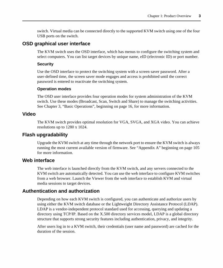
OSD graphical user interfaceThe KVM switch uses the OSD interface, which has menus to configure the switching system and select computers. You can list target devices by unique name, eID (electronic ID) or port number.
Security
Use the OSD interface to protect the switching system with a screen saver password. After a user-defined time, the screen saver mode engages and access is prohibited until the correct password is entered to reactivate the switching system.
Operation modes
The OSD user interface provides four operation modes for system administration of the KVM switch. Use these modes (Broadcast, Scan, Switch and Share) to manage the switching activities. See Chapter 3, “Basic Operations”, beginning on page 16, for more information.
VideoThe KVM switch provides optimal resolution for VGA, SVGA, and XGA video. You can achieve resolutions up to 1280 x 1024.
Flash upgradabilityUpgrade the KVM switch at any time through the network port to ensure the KVM switch is always running the most current available version of firmware. See “Appendix A” beginning on page 105 for more information.
Web interfaceThe web interface is launched directly from the KVM switch, and any servers connected to the KVM switch are automatically detected. You can use the web interface to configure KVM switches from a web browser. Launch the Viewer from the web interface to establish KVM and virtual media sessions to target devices.
Authentication and authorizationDepending on how each KVM switch is configured, you can authenticate and authorize users by using either the KVM switch database or the Lightweight Directory Assistance Protocol (LDAP). LDAP is a vendor-independent protocol standard used for accessing, querying and updating a directory using TCP/IP. Based on the X.500 directory services model, LDAP is a global directory structure that supports strong security features including authentication, privacy, and integrity.
After users log in to a KVM switch, their credentials (user name and password) are cached for the duration of the session.

Chapter 1: Product Overview 4
Video ViewerControl the keyboard, monitor, and mouse functions of individual target devices with the Video Viewer. You can use predefined macros and choose which macro group is displayed on the Video Viewer Macros menu.
The Video Viewer also provides access to the Virtual Media window. You can use the Virtual Media window to map drives from a target device to physical drives, such as a disk, flash, CD or DVD drive on the client computer. See Chapter 7, “Virtual Media Guide”, beginning on page 92, for more information.
Network Access SoftwareFrom the Network Access Software, you can view the KVM switches and target devices defined in the local database. Built-in groupings such as KVM switches and devices provide a way to list units. You can create custom groups of units by adding and naming folders. Other groupings are also available, based on custom fields that you assign to units. From the Network Access Software, select a target device from a Unit list, then click an icon to open a video viewer session to it.
Figure 1.2: Example KVM switch configuration
NOTE: To enable server access to USB media devices, utilize the LAN connection via the KVM USB VM server module path.
APC KVM switch
Digital users
Rack of
Virtual mediadevice
Ethernet
Local User
target devices

Chapter 1: Product Overview 5
ModemThe KVM switch supports v.90 modems at 57.6 kbits/s full-duplex connected to the modem port. When using a modem-based connection, you can launch a Video Viewer to a server but Virtual Media will not be available. When launched, the Video Viewer displays the server image in grayscale at a resolution of 640x480 pixels to optimize responsiveness to mouse movements by the user. You can not initiate a scan of multiple servers or initiate firmware upgrade with a modem-based connection.

6
CHAPTER
2 Installation
The APC KVM switch requires connectivity to a computer running Network Access Software. Use Network Access Software to view and control target devices (one at a time) attached to the KVM switch. The analog port does not require the Network Access Software for operation. The analog port uses the OSD graphical user interface. For more information, see Basic Operations on page 16 and Network Access Software on page 35.
The KVM switch transmits KVM information between operators and target devices attached to the KVM switch over a network using either an Ethernet or local connection.
The KVM switch uses TCP/IP for communication over Ethernet. Although 10BASE-T Ethernet can be used, using a dedicated, switched 100BASE-T network or a 1000BASE-T network will improve performance.
Installing And Setting Up The KVM SwitchConnecting the KVM switch
To connect and turn on the KVM switch:
1. Turn off target devices that are part of the switching system. Connect one end of the power cord to the rear of the KVM switch and connect the other end to an AC power source.
2. Connect a VGA monitor and either PS/2 or USB keyboard and mouse cables into the labeled KVM switch ports. You must install both a keyboard and mouse on the local ports or the keyboard will not initialize correctly. You cannot connect a DVI or EGA monitor to the KVM switch.
3. Connect one end of a CAT5 patch cable into a target device interface port and connect the other end into the RJ-45 connector of a KVM server module. Plug one end of a CAT5 patch cable into the KVM server module port and plug the other end into the RJ-45 connector of a KVM server module.
4. Connect the KVM server module into the correct ports on the rear of the target device. Repeat this procedure for all target devices to be connected to the KVM switch.
5. Connect a CAT5 patch cable from the Ethernet network into the LAN port on the rear of the KVM switch. Network users will access the KVM switch through this port.

Chapter 2: Installation 7
6. If you configure the switch using the console menu interface, connect a terminal or PC running terminal emulation software to the SETUP port on the back panel of the switch using the supplied cable. The terminal should be set to 9600 bits per second (bps), 8 bits, 1 stop bit, no parity and no flow control. Otherwise, proceed to the next step.
7. Turn on each target device and then turn on the KVM switch. After approximately one minute, the KVM switch completes initialization and opens the OSD graphical user interface Free tag on the local port monitor.
8. Use the web interface or the Network Access Software to configure the KVM switch.
Connecting a KVM server module to each target device To connect a KVM server module to a target device:
1. Attach the color-coded connectors of the KVM server module to the keyboard, monitor and mouse ports on the first target device you connect to the KVM switch.
2. Attach one end of the CAT5 cable to the RJ-45 connector on the KVM server module.3. Connect the other end of the CAT5 cable to a target device interface port on the rear of the
KVM switch.
Repeat steps 1 to 3 for all target devices to be attached.
WARNING: To reduce the risk of electric shock or damage to your equipment: - Do not disable the power cord grounding plug. The grounding plug is an important safety feature. - Plug the power cord into a grounded (earthed) outlet that is easily accessible at all times. - Disconnect the power from the switch by unplugging the power cord from either the electrical outlet or the
KVM switch. - The AC inlet is the main power disconnect.
Setting up the networkThe KVM switch and KVM server modules use IP addresses to uniquely identify the KVM switch and target devices. The KVM switch supports both Dynamic Host Configuration Protocol (DHCP) and static IP addressing. To avoid confusion, reserve IP addresses for each KVM switch and ensure the IP addresses remain static while the KVM switch is connected to the network. For additional information on setting up the KVM switch using the Network Access Software, and for information on how the KVM switch uses TCP/IP, see See “Network Access Software” on page 35..

Chapter 2: Installation 8
Figure 2.1: KVM switch configuration example
Verifying Ethernet connections
The Ethernet connection has two LEDs. The green LED on the right is the Link indicator. It is lit when a valid connection to the network is established, and it flashes when there is activity on the port. The amber/green LED on the left indicates the device is communicating at 100 Mbps (amber) or 1000 Mbps (green) when using the Ethernet connection.
Connecting local peripheral devicesTo connect local peripheral devices to the KVM switches:
Connect a keyboard, monitor and mouse to each set of color-coded ports on the rear of the KVM switch.
To connect local virtual media:
Connect the virtual media to any of the four USB ports on the KVM switch. For all virtual media sessions, you must use a KVM USB VM server module.
Adjusting mouse settings
Before a computer connected to the KVM switch can be used for remote user control, you must set the target mouse speed and turn off acceleration.
Modem
Servers
PDU
AP5610 Switch
Local User
Interface ports
Telephone Network
Digital User Ethernet
ModulesServer
Chapter 2: Installation 9
If you are experiencing slow mouse response during a remote video session, deactivate mouse acceleration in the operating system of the target device and set the mouse speed at 50%.
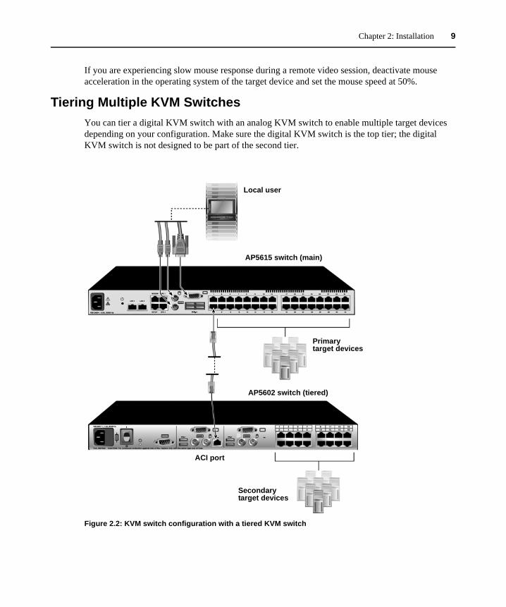
Tiering Multiple KVM SwitchesYou can tier a digital KVM switch with an analog KVM switch to enable multiple target devices depending on your configuration. Make sure the digital KVM switch is the top tier; the digital KVM switch is not designed to be part of the second tier.
Figure 2.2: KVM switch configuration with a tiered KVM switch
Local user
AP5615 switch (main)
Primary target devices
ACI port
Secondary target devices
AP5602 switch (tiered)
Chapter 2: Installation 10
NOTE: To open a virtual media session with a target device, the target device must first be connected to the KVM switch using a KVM USB VM server module or KVM PS/2 VM server module.
To tier multiple KVM switches:
1. Connect the tiered KVM switch to each target device as described in Connecting the KVM switch on page 6.
2. Connect the peripheral devices to the local user port on the digital KVM switch. See Verifying Ethernet connections on page 8.
3. Attach one end of the CAT5 cable to the ACI port on the analog KVM switch.4. Attach the other end of the CAT5 cable to one of the target device interface ports on the rear of
the digital KVM switch.5. The switching system automatically merges the two KVM switches. All target devices
connected to the tiered KVM switch are included in the main KVM switch target device list in the OSD interface. Repeat steps 3 and 4 for all additional tiered KVM switches you attach.
Installing And Starting Up The Web InterfaceOnce you have installed a new digital KVM switch, you can use the web interface to configure unit parameters and launch video sessions.
Supported browsersThe web interface supports the following browsers:
• Microsoft Internet Explorer® version 6.0 or later• Mozilla Firefox® version 2.0 or later• Netscape Navigator® version 7.0 or later
Launching the web interfaceTo launch the web interface:
1. Open a web browser and type the IP address of the KVM switch. You can set the IP address of the KVM switch using the OSD or the serial port.
2. The log in window opens. Type your user name and password and click OK. 3. The web interface opens and displays the Connections tab.
NOTE: Once you have logged in to the web interface, you will not have to log in again when launching new sessions unless you have logged out or your session has exceeded the inactivity timeout specified by the administrator.

Chapter 2: Installation 11
Installing And Starting Up The Network Access SoftwareSupported operating systems
The following operating systems are supported by the Network Access Software:
• Microsoft® Windows® 2000 Workstation Service Pack 4• Microsoft Windows 2000 Server Service Pack 4• Microsoft Windows XP (Home and Professional) Service Pack 2• Microsoft Windows Server 2003 Service Pack 1• Red Hat Enterprise Linux 3.0 WS• Red Hat Enterprise Linux 4.0 WS• SuSE Linux Enterprise Server 8• SuSE Linux Enterprise Server 9• SuSE Linux 9.2• SuSE Linux 9.3
Hardware configuration requirementsThe software is supported on the following minimum computer hardware configurations:
• 500 MHz Pentium III • 256 MB RAM• 10BASE-T or 100BASE-T NIC• XGA video with graphics accelerator• Desktop size must be a minimum of 800 x 600• Color palette must be a minimum of 65,536 (16-bit) colors
Browser requirementsYou will need one of the following browsers installed on the computer to run the Network Access Software:
• Internet Explorer 5.0 or later (Windows only)• Netscape 6.0 or later• Mozilla™ 1.4 or later• Firefox 1.0 or later
Installing the softwareTo install on Microsoft Windows operating systems:
1. Insert the CD included with the KVM switch into the CD drive.

Chapter 2: Installation 12
If AutoPlay is supported and enabled, the setup program starts automatically.
— or —
If the computer does not support AutoPlay, set the default drive to the CD drive letter and execute the following command to start the install program (replace “drive” with the CD drive letter on the system): drive:\Network Access Software\win32\setup.exe
2. Follow the on-screen instructions.
To install on Linux operating systems:
1. Insert the CD included with KVM switch into the CD drive.
When using Red Hat and SUSE Linux distributions, the CD will usually be mounted automatically.
Continue with step 2 if the CD mounts automatically.
If the CD does not mount automatically, issue the mount command manually. The following is an example of a typical mount command:
mount -t iso9660 device_file mount_point
where device_file is the system-dependent device file associated with the CD and mount_point is the directory that will be used to access the contents of the CD after it is mounted. Typical default values include "/mnt/cdrom" and "/media/cdrom".
See the Linux operating system documentation for the specific mount command syntax to use.
2. Open a command window and navigate to the CD. For example: cd /mnt/cdrom
3. Enter the following command to start the install program:sh ./Network Access Software/linux/setup.bin
4. Follow the on-screen instructions.
During installation
You are prompted to select the location where the application will be installed. Select an existing path or type a directory path. The default path for Windows 2000, 2003 and XP systems is the program files directory. The default path for Linux systems is the usr/lib directory.
If you enter a path that does not exist, the installation program automatically creates it during installation.
You can also indicate if you want a Network Access Software icon installed on the desktop.
Chapter 2: Installation 13
Uninstalling the softwareTo uninstall the software on Microsoft Windows, starting at the Control Panel:
1. Open the Control Panel and select Add/Remove Programs. A sorted list of currently installed programs opens.
2. Select the Network Access Software entry.3. Click the Change/Remove button. The uninstall wizard starts.4. Click the Uninstall button and follow the on-screen instructions.
To uninstall the software on Microsoft Windows, using a command window:
1. Open a command window and change to the Network Access Software install directory used during installation. The default path for win32 systems is the program files directory.
2. Change to the UninstallerData subdirectory and enter the following command (the quotation marks are required):
“Uninstall APC Network Access Software.exe”
The uninstall wizard starts. Follow the on-screen instructions.
To uninstall the software on Linux:
1. Open a command window and change to the Network Access Software install directory used during installation. The default path for Linux systems is the usr/lib directory.
2. Change to the UninstallerData subdirectory and enter the following command:sh ./Uninstall_APC_Network_Access_Software
The uninstall wizard starts. Follow the on-screen instructions.
Opening the softwareTo open the software on Microsoft Windows:
1. Select Start - Programs - Network Access Software.2. Double-click the Network Access Software icon.
To open the software on Linux:
1. Enter the command: /Network_Access_Software
2. From (/user/bin), enter the following link: /APC_Network_Access_Software
3. If a desktop shortcut was created on installation, double-click the shortcut.
Chapter 2: Installation 14
Setting up the softwareTo set up the software:
1. Install the software on each computer. 2. From one computer, open the software. 3. Click the New KVM switch button to add a KVM switch to the software database. The New
KVM switch Wizard opens.
— or —
Select Tools > Discover from the software menu to search for all KVM switches.
4. Use the Network Access Software to set unit properties, options and other customization as needed.
5. Select a KVM switch and click the Manage KVM switch button to create local user accounts through the web interface.
6. From the web interface, set the names of all target devices.7. Repeat steps 3 through 6 for each KVM switch you want to manage.8. After one Network Access Software environment is set up, select File > Database > Save to
save a copy of the local database with all the settings. 9. From the software on a second computer, select File > Database > Load and browse to the file
you have saved. Select the file and then click Load. Repeat this step for each client computer you want to set up.
10. To access a target device attached to a KVM switch, select the target device in the Network Access Software and click the Connect Video or Browse button to open a session (only the corresponding button for the selected target device is visible).
Rack Mounting A KVM SwitchA rack mounting kit is supplied with each KVM switch. You may either place the KVM switch on the rack shelf or mount the switch directly into an Electronic Industries Alliance (EIA) standard rack. Most KVM switches may be rack mounted in a 1U configuration. The APC KVM Switch family does not support a 0U configuration.
Rack mount safety considerationsRack Loading: Overloading or uneven loading of racks may result in shelf or rack failure, causing damage to equipment and possible personal injury. Stabilize racks in a permanent location before loading begins. Mount components beginning at the bottom of the rack, then work to the top. Do not exceed your rack load rating.
Power Considerations: Connect only to the power source specified on the unit. When multiple electrical components are installed in a rack, ensure that the total component power ratings do not

Chapter 2: Installation 15
exceed circuit capabilities. Overloaded power sources and extension cords present fire and shock hazards.
Elevated Ambient Temperature: If the unit is installed in a closed rack assembly, the operating temperature of the rack environment may be greater than room ambient temperature. Do not exceed the rated maximum ambient temperature of the switch.
Reduced Air Flow: Install the equipment in the rack so that the amount of airflow required for safe operation of the equipment is not compromised.
Reliable Earthing: Maintain reliable earthing of rack-mounted equipment. Pay particular attention to supply connections and indirect connections to the branch circuit (for example, use of power strips).
Installing a rack mounting bracketTo install a rack mounting bracket:
1. Attach the brackets to the switch using the six provided screws. 2. Install the cable support rod on the lower side of the slide extensions. 3. Slide the extension assembly into the bracket assembly. 4. Place the complete bracket assembly into a level rack position and install the appropriate
hardware (not included) into each of the four bracket corners.
16
CHAPTER
3 Basic Operations
Controlling The Switching System From The Analog PortThe APC KVM switch includes ports on the rear panel to connect a keyboard, monitor and mouse for direct analog access. The KVM switch uses the On-Screen Display (OSD), which has menus to configure the switching system and select target devices. Devices can be identified by customizable names.
Starting The OSDYou can view, configure and control target devices in the switching system from the OSD interface from a KVM connection to the analog port.
To start the OSD interface, press Print Screen. Alternatively, you can press the Control, Alt or Shift key twice within one second to start the OSD interface. You can use any of these key sequences instead of pressing Print Screen in any procedure in this document. To specify which key sequences can be used to start the OSD interface, click Setup - Menu.
The Main window lists the target devices in the switching system. You can sort the list by clicking the Name, eID or Port button.
The Port column indicates the target device interface port to which each target device is connected.
The status of each target device in the switching system is indicated by one or more status symbols in the right column. The following table describes the status symbols.

Chapter 3: Basic Operations 17
You can set a screen delay to specify the length of time that elapses between when Print Screen is pressed and when the OSD interface starts.
To set a screen delay:
1. Press Print Screen to start the OSD interface.2. In the Main window, click Setup — Menu.3. In the Screen Delay Time field, type the number of seconds you want to elapse between when
Print Screen is pressed and when the OSD interface starts.
Connecting A User To A Target DeviceUse the Main window of the OSD to select a target device to connect. When you select a target device, the keyboard and mouse are automatically reconfigured to the correct settings for that target device.
To select a target device:
1. Press Print Screen to start the OSD. 2. Double-click the target device name, eID number or port number in the main window
— or —
Table 3.1: OSD interface status symbols
Symbol Description
The KVM server module is online (green circle).
The KVM server module is offline or is not operating correctly.
The target device is tiered through another KVM switch. The target device and the KVM switch are online and have power.
The target device is tiered through another KVM switch. The KVM switch is offline or does not have power.
The firmware for the KVM server module is being upgraded (yellow circle). When this symbol is visible, do not turn off and turn on the KVM switch or connected target devices and do not disconnect the KVM server module. Doing so might damage the KVM server module permanently.
The KVM server module is being accessed by the indicated user channel (green channel letter).
The KVM server module is blocked by the indicated user channel (black channel letter).
A remote virtual media connection is established to the target device connected to the indicated user channel (blue letter).
Chapter 3: Basic Operations 18
Type the port number and press Enter
— or —
Type the first few characters of the target device name or eID number, and press Enter.
You can also toggle between two selected target devices.
To select the previously selected target device:
Press Print Screen and then press Backspace.
To disconnect the user from a target device:
Press Print Screen and press Alt+0. A Free status flag in the OSD indicates the user is not connected to a target device.
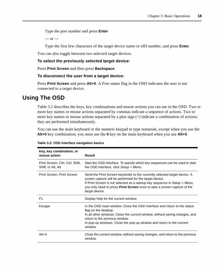
Using The OSDTable 3.2 describes the keys, key combinations and mouse actions you can use in the OSD. Two or more key names or mouse actions separated by commas indicate a sequence of actions. Two or more key names or mouse actions separated by a plus sign (+) indicate a combination of actions; they are performed simultaneously.
You can use the main keyboard or the numeric keypad to type numerals, except when you use the Alt+0 key combination; you must use the 0 key on the main keyboard when you use Alt+0.
Table 3.2: OSD interface navigation basics
Key, key combination, or mouse action Result
Print Screen; Ctrl, Ctrl; Shift, Shift; or Alt, Alt
Start the OSD interface. To specify which key sequences can be used to start the OSD interface, click Setup > Menu.
Print Screen, Print Screen Send the Print Screen keystroke to the currently selected target device. A screen capture will be performed for the target device.If Print Screen is not selected as a startup key sequence in Setup > Menu, you only need to press Print Screen once to take a screen capture of the target device.
F1 Display help for the current window.
Escape In the OSD main window: Close the OSD interface and return to the status flag on the desktop.In all other windows: Close the current window, without saving changes, and return to the previous window.In pop-up windows: Close the pop-up window and return to the current window.
Alt+X Close the current window, without saving changes, and return to the previous window.
Chapter 3: Basic Operations 19
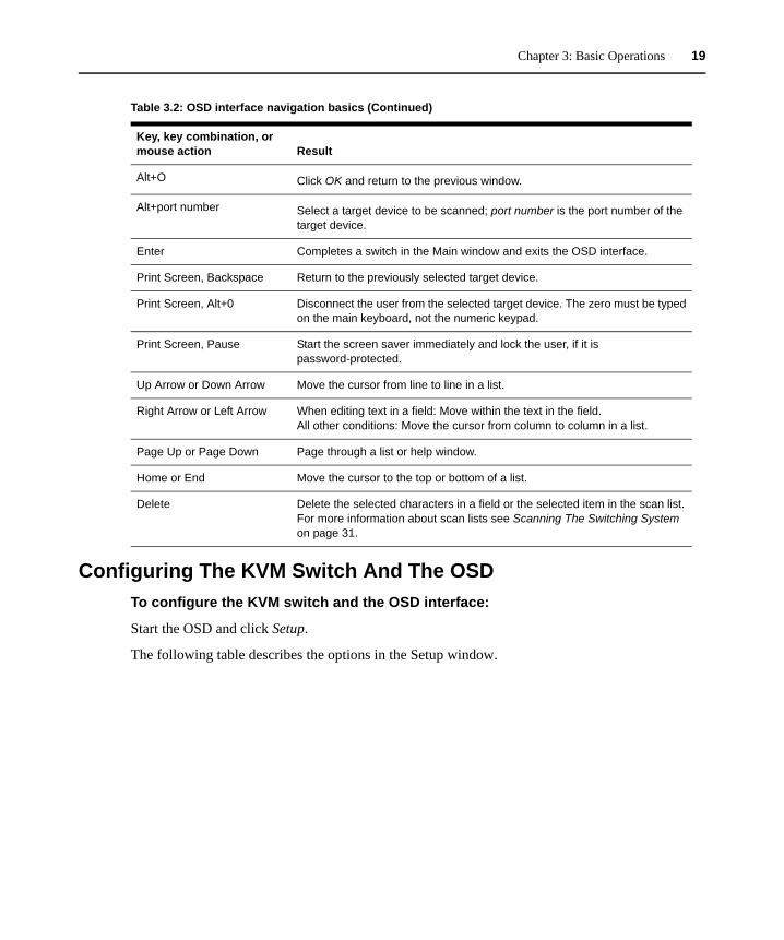
Configuring The KVM Switch And The OSDTo configure the KVM switch and the OSD interface:
Start the OSD and click Setup.
The following table describes the options in the Setup window.
Alt+O Click OK and return to the previous window.
Alt+port number Select a target device to be scanned; port number is the port number of the target device.
Enter Completes a switch in the Main window and exits the OSD interface.
Print Screen, Backspace Return to the previously selected target device.
Print Screen, Alt+0 Disconnect the user from the selected target device. The zero must be typed on the main keyboard, not the numeric keypad.
Print Screen, Pause Start the screen saver immediately and lock the user, if it is password-protected.
Up Arrow or Down Arrow Move the cursor from line to line in a list.
Right Arrow or Left Arrow When editing text in a field: Move within the text in the field.All other conditions: Move the cursor from column to column in a list.
Page Up or Page Down Page through a list or help window.
Home or End Move the cursor to the top or bottom of a list.
Delete Delete the selected characters in a field or the selected item in the scan list. For more information about scan lists see Scanning The Switching System on page 31.
Table 3.2: OSD interface navigation basics (Continued)
Key, key combination, or mouse action Result
Chapter 3: Basic Operations 20
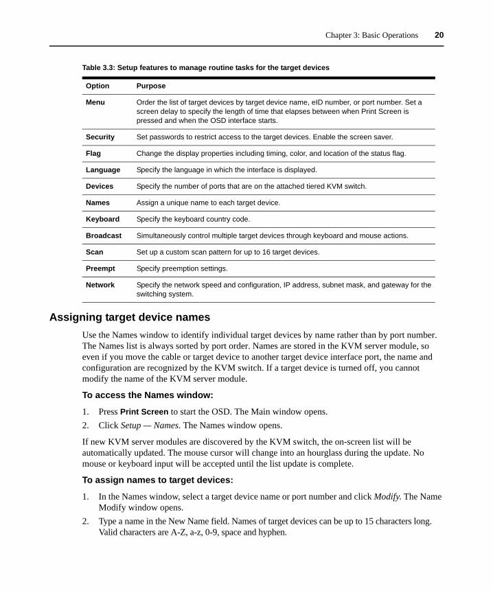
Assigning target device namesUse the Names window to identify individual target devices by name rather than by port number. The Names list is always sorted by port order. Names are stored in the KVM server module, so even if you move the cable or target device to another target device interface port, the name and configuration are recognized by the KVM switch. If a target device is turned off, you cannot modify the name of the KVM server module.
To access the Names window:
1. Press Print Screen to start the OSD. The Main window opens.2. Click Setup — Names. The Names window opens.
If new KVM server modules are discovered by the KVM switch, the on-screen list will be automatically updated. The mouse cursor will change into an hourglass during the update. No mouse or keyboard input will be accepted until the list update is complete.
To assign names to target devices:
1. In the Names window, select a target device name or port number and click Modify. The Name Modify window opens.
2. Type a name in the New Name field. Names of target devices can be up to 15 characters long. Valid characters are A-Z, a-z, 0-9, space and hyphen.
Table 3.3: Setup features to manage routine tasks for the target devices
Option Purpose
Menu Order the list of target devices by target device name, eID number, or port number. Set a screen delay to specify the length of time that elapses between when Print Screen is pressed and when the OSD interface starts.
Security Set passwords to restrict access to the target devices. Enable the screen saver.
Flag Change the display properties including timing, color, and location of the status flag.
Language Specify the language in which the interface is displayed.
Devices Specify the number of ports that are on the attached tiered KVM switch.
Names Assign a unique name to each target device.
Keyboard Specify the keyboard country code.
Broadcast Simultaneously control multiple target devices through keyboard and mouse actions.
Scan Set up a custom scan pattern for up to 16 target devices.
Preempt Specify preemption settings.
Network Specify the network speed and configuration, IP address, subnet mask, and gateway for the switching system.

Chapter 3: Basic Operations 21
3. Click OK to transfer the new name to the Names window. The selection is not saved until you click OK in the Names window.
4. Repeat steps 1 to 3 for each target device in the switching system.5. Click OK.
If a KVM server module has not been assigned a name, the eID is used as the default name. To list target devices alphabetically by name, press Alt+N or click Name in the Main window.
Assigning device typesThe KVM switch automatically discovers an attached tiered analog KVM switch, but you must specify the number of ports on the tiered KVM switch through the Devices window. KVM switches are listed in the Type category for the tiered KVM switch. When you select a configurable KVM switch from the list, the Modify button becomes available, so you can assign it the correct number of ports.
To access the Devices window:
1. Press Print Screen to start the OSD. The Main window opens.2. Click Setup — Devices. The Devices window opens.
When the KVM switch discovers a tiered KVM switch, the port numbering changes to accommodate each target device under that KVM switch. For example, if the KVM switch is connected to target device interface port 6, the KVM switch port is listed as 06, and the target devices under it are numbered sequentially as 06-01, 06-02 and so on.
To assign a device type:
1. In the Devices window, select the port number, then click Modify. The Device Modify window opens.
2. Select or type the number of ports that are supported by the tiered KVM switch and click OK.3. Repeat steps 1 and 2 for each port for which you want to assign a device type.4. Click OK in the Devices window to save settings.
Changing the display behaviorUse the Menu window to change the order of the target devices and set a screen delay for the OSD interface. The display order setting affects the order in which target devices are listed in several windows, including the Main, Devices and Broadcast windows.
To access the Menu window:
1. Press Print Screen to start the OSD. The Main window opens.2. Click Setup — Menu. The Menu window opens.
To select the order of the target devices:
1. Select Name to list the target devices alphabetically by target device name.

Chapter 3: Basic Operations 22
— or —
Select eID to list the target devices numerically by eID number.
— or —
Select Port to list the target devices numerically by port number.
2. Click OK.
To select a key combination to start the OSD interface:
1. In the Invoke OSD section, select the key combinations that will start the OSD, then press your selected combination.
2. Click OK.
You can set a screen delay so that you can select a target device using the keyboard without starting the OSD. A screen delay specifies the length of time that elapses between when Print Screen is pressed and when the OSD starts.
To set a screen delay:
1. Type the number of seconds (0-9) to specify the length of time that elapses between when Print Screen is pressed and when the OSD starts. If you specify 0, there is no delay.
2. Click OK.
Selecting display languageUse the Setup window to change the display language for the OSD.
To select a language for the OSD:
1. Press Print Screen to start the OSD. The Main window opens.2. Click Setup — Language. The Language window opens.3. In the Language window, select the language and click OK.
Controlling the status flagThe status flag is displayed on the desktop and indicates the name or eID number of the selected target device or the status of the selected port. You can specify the information displayed in the flag, the flag color, whether the desktop is visible through the flag, whether the flag is displayed all the time and where the flag is displayed on the desktop. The following table shows examples of status flags.

Chapter 3: Basic Operations 23
To specify the status-flag settings:
1. Press Print Screen. The Main window opens.2. Click Setup > Flag.3. (Optional) Select Name or eID to specify the information displayed in the flag. 4. (Optional) Select Displayed to display the flag all the time, or select Timed to display the flag
for only five seconds after you select a target device. 5. (Optional) In the Display Color section, select the flag color. 6. (Optional) Select Opaque to make the flag solid, or select Transparent to make the desktop
visible through the flag. 7. (Optional) To specify the position of the flag:
a. Click Set Position.b. Hold down the left mouse button on the title bar of the Set Position window and drag the
window to the new location.c. Press the right mouse button to close the Set Position window.
8. Click OK to save the changes.
Setting the keyboard country codeBy default, the KVM switch sends the US keyboard country code to USB cables attached to target devices, and the code is applied to the target devices when they are turned on or rebooted. Codes are then stored in the KVM server module. Using a keyboard code that supports a language different from that of the KVM switch firmware will cause incorrect keyboard mapping.
If multiple keyboards are connected to the local port, they must be of the KVM server module type (PC or Mac) and of the KVM server module language. Only local users can view or change keyboard country code settings.
Issues might arise when you use the US keyboard country code with a keyboard of another country. For example, the Z key on a US keyboard is in the KVM server module location as the Y key on a German keyboard.
Table 3.4: OSD interface status flags
Flag Description
Flag type by name.
Flag type by eID number.
Flag indicating that the user has been disconnected from all systems.
Flag indicating that Broadcast mode is enabled.
Chapter 3: Basic Operations 24
You can use the Keyboard window to send a different keyboard country code than the default US setting.
To change the keyboard country code:
1. Press Print Screen to start the OSD. The Main window opens.2. Click Setup — Keyboard. The Keyboard window opens.3. Select the country code for the keyboard and click OK. Confirm the change in the Keyboard
Warning window.4. Click OK.
Setting KVM switch securityYou can enable a screen saver to start if the user remains inactive for a specified length of time. When the screen saver starts, the user is disconnected from any target device to which it was connected. The screen saver stops when you press any key or move the mouse.
If you set a password, the keyboard and mouse are locked when the screen saver starts. When you press a key or move the mouse while the screen saver is running, a Password window opens, and you must type the password and click OK to unlock the keyboard and mouse.
NOTE: If you forget the password, you must call APC technical support.
To immediately start the screen saver:
Press Print Screen and click Pause.
To enable the screen saver:
1. Press Print Screen. The main window opens.2. Click Setup — Security. If a password is set, the Password window opens. Type the password
and click OK.3. Select the Enable Screen Saver checkbox.4. In the Inactivity Time field, type the number of seconds (1-99) that must elapse before the
screen saver starts.5. If the monitor is Energy Star compliant, select Energy; otherwise, select Screen.6. (Optional) To run the screen-saver test, click Test. The screen-saver test runs for 10 seconds.7. Click OK.
To disable the screen saver:
1. Press Print Screen. The main window opens.2. Click Setup — Security. If a password is set, the Password window opens. Type the password
and click OK.3. Clear the Enable Screen Saver checkbox.
Chapter 3: Basic Operations 25
4. Click OK.
A password must contain both alphabetic and numeric characters and can contain up to 12 characters. Passwords are case-sensitive. Valid characters are A-Z, a-z, 0-9, space and hyphen.
To set or change a password:
1. Press Print Screen. The main window opens.2. Click Setup — Security. If a password is already set, the Password window opens. Type the
password and click OK.3. Double-click the New field.4. In the New field, type the new password.5. In the Repeat field, type the password again.6. Click OK.
To disable password protection:
1. Press Print Screen. The main window opens.2. Click Setup — Security. In the Password window, type the password and click OK.3. Double-click the New field. Leave the field blank and press Enter.4. Double-click the Repeat field. Leave the field blank and press Enter.5. Click OK.
Setting The Preemption WarningAdministrators and users with certain access rights can preempt (disconnect) KVM sessions and take control of the target device. You can choose whether to warn the first user the session will be preempted and specify how long the KVM switch will wait for the first user to respond to the warning.
For more information about preemption, see Using Preemption on page 76.
To view or change the preemption warning settings:
1. Press Print Screen. The main window opens.2. Click Setup — Preempt.3. Enter a number of seconds in the Timeout Seconds field.
NOTE: If you enter a value of 0-4 seconds, the first user will not be warned before the session is preempted. If you enter a value of 5-120 seconds, the first user will be warned and will be allowed to continue using the target device for up to the amount of time in the Timeout Seconds field. The session will be preempted when the user clicks OK, or when the specified time elapses.
4. Click OK to save the settings.

Chapter 3: Basic Operations 26
Managing Target Device Tasks Using The OSDFrom the Commands window, you can manage the switching system and user connections, enable the Scan and Broadcast modes, and update the firmware.
To access the Commands window:
1. Press Print Screen. The Main window opens.2. Click Commands. The Commands window opens.
Displaying version informationYou can use the OSD to view the versions of the KVM switch and the KVM server module firmware.
To view version information:
1. Press Print Screen. The Main window opens.2. Click Commands — Display Versions. The Version window opens. The top pane of the window
lists the subsystem versions in the KVM switch.3. Click the KVM server module button to view individual KVM server module version
information. The KVM server module Select window opens.4. Select a KVM server module to view and click the Version button. The KVM server module
Version window opens.5. Click X to close the KVM server module Version window.
Table 3.5: Commands to manage routine tasks for the target device
Feature Purpose
KVM server module Status
View the version and upgrade status of the KVM server module.
Display Config View current display settings.
Run Diagnostics Configure and begin diagnostics on target devices.
Broadcast Enable Begin broadcasting to the target devices. Configure a target device list for broadcasting under the Setup window.
Scan Enable Begin scanning the target devices. In the Setup window, set up a target device list for scanning.
User Status View and disconnect users.
Display Versions View version information for the KVM switch as well as view and upgrade firmware for individual KVM server modules.
Device Reset Re-establish operation of the keyboard and mouse.
Chapter 3: Basic Operations 27
Upgrading the firmwareYou can also use the OSD interface to upgrade the firmware available for the KVM switch. For optimum performance, keep the firmware current. For more information on upgrading firmware, see “Appendix A” beginning on page 105.
To upgrade firmware:
1. Press Print Screen. The Main window opens.2. Click Commands — Display Versions — Upgrade. The Upgrade window opens.3. Click Upgrade. A Warning window opens. Click OK to open the Upgrade Process window.
The progress of the upgrade is indicated in the Programmed field.
Viewing the display configurationUse the Display Configuration window to view the current configuration of the switching system.
To view the current configuration:
Click Commands — Display Config. The Display Configuration window opens and lists the current system configuration values.
Viewing and disconnecting user connectionsYou can view and disconnect users from target devices through the User Status window. You can display either the target device name or eID number to which a user is connected. If there is no user connected to a channel, the User and Server Name fields are blank.
To view current user connections:
Click Commands — User Status. The User Status window opens.
To disconnect a user:
1. From the User Status window, click the letter that corresponds to the user to disconnect. The Disconnect window opens.
2. Click OK to disconnect the user and return to the User Status window.
If the User Status list has changed since it was last visible, the mouse cursor will turn into an hourglass as the list is automatically updated. No mouse or keyboard input is accepted until the list update is complete.
Resetting the keyboard and mouse If the local keyboard and mouse are not responding, reset the local keyboard and mouse and reset the keyboard and mouse on the target device.
When you reset the keyboard and mouse on the target device, the keyboard and mouse settings are sent to the KVM switch and communication is re-established between the KVM switch and the target device.
Chapter 3: Basic Operations 28
NOTE: This function is for Microsoft Windows-based computers only. Resetting the keyboard and mouse on a target device running any other operating system might require you to reboot that target device.
To reset the local mouse and keyboard
1. Press Print Screen. The Main window opens.2. Click Commands — Device Reset. 3. Click Version > Reset. A message is displayed stating the mouse and keyboard are reset. 4. Click OK.
Power Controlling DevicesPower window
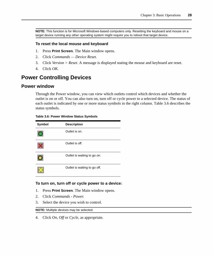
Through the Power window, you can view which outlets control which devices and whether the outlet is on or off. You can also turn on, turn off or cycle power to a selected device. The status of each outlet is indicated by one or more status symbols in the right column. Table 3.6 describes the status symbols.
To turn on, turn off or cycle power to a device:
1. Press Print Screen. The Main window opens.2. Click Commands - Power. 3. Select the device you wish to control.
NOTE: Multiple devices may be selected.
4. Click On, Off or Cycle, as appropriate.
Table 3.6: Power Window Status Symbols
Symbol Description
Outlet is on.
Outlet is off.
Outlet is waiting to go on.
Outlet is waiting to go off.

Chapter 3: Basic Operations 29
PDUs windowThrough the PDUs window, you can view which rack PDUs are connected to your system. The status of each rack PDU is indicated by one or more status symbol in the right column. Table 3.7 describes the status symbols.
To view connected rack PDUs:
Open the PDUs window. The window contains a listing of all rack PDUs attached to your system.
PDU Settings windowFrom the PDUs window, you can view the PDU Settings window, which allows you to view and modify rack PDU parameters.
To view/modify PDU settings:
1. Press Print Screen. The Main window opens.2. Click Setup - PDUs. 3. Complete one of the following steps:
Select a rack PDU name, then click Settings to open the PDU Settings window.
— or —
Select a rack PDU name, then press Enter to open the PDU Settings window.
— or —
Double-click on the rack PDU name to open the PDU Settings window.
4. Complete any of the following steps:a. In the Name field, enter the rack PDU name.b. In the Cycle Delay field, enter the number of seconds you want the KVM switch to wait
between turning off and turning on.5. Click OK.
Table 3.7: PDUs WIndow Status Symbols
Symbol Description
Outlet is online.
Outlet is offline.
Outlet is overloaded.
Chapter 3: Basic Operations 30
PDU Inlets windowFrom the Inlets window, you can view and modify inlet parameters.
NOTE: You can only modify inlet parameters on a PDU that is currently online.
To view/modify PDU Inlet settings:
1. Press Print Screen. The Main window opens.2. Click Setup - PDUs. 3. Complete one of the following steps:
Select a rack PDU name, then click Settings to open the PDU Settings window.
— or —
Select a rack PDU name, then press Enter to open the PDU Settings window.
— or —
Double-click on the rack PDU name to open the PDU Settings window.
4. Click Inlets.5. Enter an integer in the Minimum Amps or Maximum Amps fields.6. Click OK.
PDU Outlets windowFrom the Outlets window, you can select an outlet and open the Outlet Settings window to set outlet-specific parameters.
NOTE: You can only modify outlet parameters on a PDU that is currently online.
To view/modify PDU Outlet settings:
1. Press Print Screen. The Main window opens.2. Click Setup - PDUs. 3. Complete one of the following steps:
Select a rack PDU name, then click Settings to open the PDU Settings window.
— or —
Select a rack PDU name, then press Enter to open the PDU Settings window.
— or —
Double-click on the rack PDU name to open the PDU Settings window.
4. Click Outlets.

Chapter 3: Basic Operations 31
5. Complete one of the following steps:
Select an outlet, then click Settings to open the Outlet Settings window.
— or —
Select an outlet, then press Enter to open the Outlet Settings window.
— or —
Double-click an outlet to open the Outlet Settings window.
6. Select the outlet you wish to modify.7. Complete any of the following steps:
a. In the Name field, enter the Outlet name.b. In the Power-On Interval field, enter the number of seconds you want the KVM switch to
wait between turning off and turning on.
NOTE: The Power-On Interval must be an integer between 0 and 7200.
8. Click OK.
Scanning The Switching SystemIn scan mode, the KVM switch automatically scans from port to port (target device to target device). Use scan mode to monitor the activity of up to 16 target devices and to specify which target devices to scan and the number of seconds each target device will be visible. The target devices are scanned in the order in which they are listed. You can choose to list the target devices by name, eID number or port number by clicking the corresponding button.
To add target devices to the scan list:
1. Click Setup — Scan. The Scan window opens.2. The window contains a listing of all target devices attached to the KVM switch. Select the
checkbox next to the target devices to scan.
— or —
Double-click on the target device name or port to scan.
— or —
Press Alt and the eID number of the target device to scan. You can select up to 16 target devices from the list.
3. In the Time field, type the number of seconds (from 3 to 255) that must elapse before the scan moves to the next target device in the sequence.
4. Click OK.

Chapter 3: Basic Operations 32
To remove a target device from the scan list:
1. In the Scan window, clear the checkbox next to the target device to remove.
— or —
Double-click on the target device name or port to remove.
— or —
Press Shift + Delete to remove the selected target device and all entries below it.
— or —
Click the Clear button to remove all target devices from the scan list.
2. Click OK.
To start the Scan mode:
1. Click Commands. The Commands window opens.2. Select Scan Enable in the Commands window. Scanning will begin immediately.3. Click X to close the Commands window.
To cancel scan mode:
If the OSD is open, select a target device.
— or —
If the OSD is not open, move the mouse or press any key on the keyboard to stop scanning at the currently selected target device.
Running Switching System DiagnosticsYou can validate the integrity of the switching system through the Run Diagnostics command. This command checks the main board functional sub-systems (memory, communications, KVM switch control and the video channels) for each system controller.
The top section of the Diagnostics window displays the hardware tests. The bottom portion divides the tested KVM server modules into three categories: Online, Offline or Suspect. KVM server modules might be listed as offline while being upgraded.
The following table details each of the tests.
Table 3.8: Diagnostic test details
Test Description
Firmware CRCs Reports on the condition of the main board RAM.
Remote User Video Reports on the condition of the remote user video.

Chapter 3: Basic Operations 33
To run diagnostic tests:
1. Click Commands — Run Diagnostics. A warning message indicates all users will be disconnected.
2. Click OK to begin diagnostics.
All users are disconnected and the Diagnostics window opens. As each test is finished, a pass (green circle) or fail (red x) symbol is visible to the left of the item. The test is complete when the last test symbol is visible.
Broadcasting To Target DevicesThe analog user can simultaneously control more than one target device in a switching system to ensure all selected target devices receive identical input. You can choose to independently broadcast either of the following actions:
• Broadcasting keystrokes — The keyboard state must be identical for all target devices receiving a broadcast to identically interpret keystrokes. Specifically, the Caps Lock and Num Lock modes must be the same on all keyboards. While the KVM switch attempts to send keystrokes to the selected target devices simultaneously, some target devices might inhibit and thereby delay the transmission.
• Broadcasting mouse movements — For the mouse to work accurately, all systems must have identical mouse drivers, desktops (such as identically placed icons) and video resolutions. In addition, the mouse must be in exactly the same place on all screens. Because these conditions are difficult to achieve, broadcasting mouse movements to multiple systems might have unpredictable results.
You can broadcast to up to 16 target devices at a time, one target device per target device interface port.
To access the Broadcast window:
1. Press Print Screen. The Main window opens.2. Click Setup > Broadcast. The Broadcast window opens.
LAN Connection Reports on the condition of the LAN connection.
Online KVM server modules
Indicates the total number of currently connected and turned on KVM server modules.
Offline KVM server modules
Indicates the number of KVM server modules that have been connected successfully in the past and are turned off.
Suspect KVM server modules
Indicates the number of KVM server modules that have been detected, but are either unavailable for connection or have dropped packets during the ping tests.
Table 3.8: Diagnostic test details

Chapter 3: Basic Operations 34
To broadcast to selected target devices:
1. Complete one of the following steps:• From the Broadcast window, select the Mouse or Keyboard checkboxes for the target
devices that are to receive the broadcast commands.• Press the Up or Down Arrow keys to move the cursor to the target device. Then press
Alt+K to select the Keyboard checkbox or Alt+M to select the Mouse checkbox. Repeat for additional target devices.
2. Click OK to save the settings and return to the Setup window, or click X or press Escape to return to the Main window.
3. Click Commands. The Commands window opens.4. Select the Broadcast Enable checkbox to activate broadcasting. The Broadcast Enable
Confirm/Deny window opens.5. Click OK to enable the broadcast, or click X or press Escape to cancel and return to the
Commands window.6. If broadcasting is enabled, type the information or perform the mouse movements that you
want to broadcast from the user station. Only target devices in the list are accessible. The other user is disabled when broadcast mode is enabled.
To turn broadcasting off:
From the Commands window, clear the Broadcast Enable checkbox.
35
CHAPTER
4 Network Access Software
About the Network Access SoftwareThe Network Access Software is the main GUI (Graphical User Interface) for the software. You can view, access, manage and create custom groupings for all supported units.
When you start the software, the main Network Access Software window opens.
Window FeaturesThe Network Access Software window is divided into areas: the View Selector buttons, the Group Selector pane and the Unit Selector pane. The content of these areas changes, based on whether a target device or an APC KVM switch is selected or what task is to be completed. Figure 4.1 on page 36 shows the window areas; descriptions follow in Table 4.1 on page 36.
Click one of the View Selector buttons to view the switching system organized by categories: KVM switches, Servers, Sites, or Folders. The Network Access Software’s default display is user-configurable. For more information, see Customizing the window display on page 37.

Chapter 4: Network Access Software 36
Figure 4.1: Network Access Software window
Table 4.1: Network Access Software window areas
Area Description
A Menu bar: Provides access to many of the features in the software.
B View Selector pane: Contains View Selector buttons for choosing the Network Access Software view. Clicking a button shows the switching system organized by the button category: KVM switches, Servers, Sites or Folders. You can configure which button is visible by default.
C Unit list: Displays a list of target devices, KVM switches and other selectable units contained in the currently selected group or the results of the search executed from the Search bar.
D Status bar: Displays the number of units shown in the Unit list.
E Unit Selector pane: Contains the Search bar, Unit lists and Task buttons that correspond to the selected view or group.
F Search bar: Gives you the ability to search the database for the text entered in the Search field.
G Task buttons: Represent tasks that can be executed. Some buttons are dynamic, based on the unit selected in the Unit list, while other buttons are fixed and always present.
D
A
B
C
E
G
F
Chapter 4: Network Access Software 37
Customizing the window displayYou can resize the Network Access Software window at any time. Each time you start the application, the Network Access Software window opens to its default size and location.
A split-pane divider that runs from top to bottom separates the Group Selector pane and the Unit Selector pane. You can move the divider left and right to change the viewing area of these two panes. Each time the Network Access Software is opened, the divider returns to its default location.
You can specify which view (KVM switches, Servers, Sites or Folders) is visible on startup or you can let the Network Access Software determine it.
You can change the order and sorting of the Unit list by clicking the sort bar above the column. An upward-pointing arrow in a column header indicates that the list is sorted by that field name in ascending order. A downward-pointing arrow indicates the list is sorted by that field name in descending order.
Adding A KVM SwitchBefore you can access the KVM switch through the software, you must add it to the software database. After a KVM switch is added, it is visible in the Unit list. You can either manually add or discover a KVM switch.
To manually add a KVM switch with an assigned IP address:
1. Select File — New — KVM switch from the Network Access Software menu.
— or —
Click the New KVM switch button.
The New KVM switch Wizard opens. Click Next.
2. Select the type of KVM switch you are adding. Click Next.3. Click Yes to indicate the KVM switch has an assigned IP address, then click Next.4. Type the IP address and click Next.5. The software searches for the KVM switch.
The software searches for the indicated unit as well as all the KVM server modules and target device names you associated with it in the OSD, if any. To search for KVM server modules that are not receiving power, access the resync feature in the Servers category of the web interface and select the Include Offline Server Access Modules checkbox.
The Enter Tier Switch Information window opens if the software detects an attached tiered switch. This window contains a list of all ports and KVM server module eIDs (Electronic Identification Numbers) retrieved from the KVM switch and the tiered switch types to which they are connected, if any. When this window first opens, all KVM switches are set to None. Detected KVM switches have an icon next to the drop-down menu.
Chapter 4: Network Access Software 38
a. The Existing cascaded Switches field contains all the current cascaded switch types defined in the database. Click Add, Delete or Modify to alter the list.
b. Associate the applicable cascaded switch types from the pull-down menus for each KVM server module that has a cascaded switch attached.
6. When you reach the final page of the Wizard, click Finish to exit the Wizard and return to the main window. The KVM switch is now included in the unit list.
To discover a KVM switch by IP address:
1. Select Tools — Discover from the Network Access Software menu. The Discover Wizard opens. Click Next.
2. The Address Range page opens. Type the range of IP addresses to search on the network in the To and From boxes. Use IP address dot notation. Click Next.
3. Complete one of the following steps:• The Searching Network progress window opens. Progress text indicates how many
addresses have been probed from the total number specified by the range, and the number of KVM switches found (for example, 21 of 100 addresses probed: 3 KVM switches found). If one or more new KVM switches are discovered, the wizard shows the Select KVM switches to Add page. From this page, you can select the KVM switches to add to the local database.
• If no new KVM switches were found, the Wizard shows the No New KVM Switches Found page. Enter a different range to search or add the KVM switches manually.
• APC Console Port Server (CPS) - When the specified CPS is found, it will be polled for server information. You can exclude ports with default names. Servers are not added to the database.
• Network Access Software - Network Access Software searches for the indicated unit and any KVM server modules and servers associated with the unit and receiving power. To search for KVM server module adaptors that are not receiving power, access the resync feature in the Servers category of the Network Access Software and enable the Include Offline KVM server module adaptors checkbox. Click Next. The Configure cascaded Switches dialog box appears if Network Access Software detects an attached legacy or analog switch. This box contains a list of all KVM server module adaptor EIDs retrieved from the KVM switch and the cascaded switches to which they are connected, if any. When this dialog box first displays, all switches will be set to None. Detected switches will have an icon next to the drop-down menu.
4. Select one or more KVM switches to add and click the Add (>) icon to move the selection or selections to the KVM switches to Add list. When the KVM switches to Add list contains all the KVM switches you want to add, click Next.
5. The Adding KVM switches progress bar window opens. Once all of the KVM switches have been added to the local database, the Discover Wizard Completed page opens. Click Finish to exit the Wizard and return to the main window. The new KVM switch is now visible in the Unit list.
Chapter 4: Network Access Software 39
If one or more KVM switches cannot be added to the local database for any reason, the Discover Wizard Not All KVM Switches Added page opens. This page lists all of the KVM switches you selected and the status for each. The status indicates if a KVM switch was added to the local database and, if not, why the process failed. Click Done when you are finished reviewing the list.
If a KVM switch already exists in the database with the KVM server module IP address as a discovered unit, then the discovered unit is ignored and is not listed on the next Wizard page.
The Discover Wizard does not automatically find target devices attached to the KVM switch. After running the Discover Wizard, access the applicable web interface and click the Resync button on the Servers category to find target devices attached to the KVM switch.
To manually install a new KVM switch with no assigned IP address:
1. Select File — New — KVM switch from the Network Access Software menu.
— or —
Click the New KVM switch button.
The New KVM switch Wizard opens. Click Next.
2. Click No to indicate the KVM switch does not have an assigned IP address, then click Next.3. The Network Address window opens. Type the IP address, subnet mask and gateway you want
to assign to the KVM switch and then click Next. 4. The software searches for any KVM switches that do not have assigned IP addresses. Select
the unit to add from the list of new KVM switches that were found and then click Next.5. The Configuring KVM switch window indicates whether the IP information was configured. If
the configuration is complete, the software searches for the new KVM switch. Click Next.
The software also searches for all KVM server modules and target device names associated with the KVM switch.
The Enter cascaded Switch Information window opens if the software detects an attached cascaded switch. This window contains a list of all ports and KVM server module eIDs retrieved from the KVM switch and the cascaded switch types to which they are connected.
a. The Existing cascaded Switches field contains all the current cascaded switch types defined in the database. Click Add, Delete or Modify to alter the list.
b. Associate the applicable cascaded switch type from the pull-down menus for each KVM server module that has a cascaded switch attached.
6. When complete, click Finish to exit the Wizard and return to the main window. The KVM switch is now included in the Unit list.
Chapter 4: Network Access Software 40
Accessing KVM SwitchesClicking the Appliances tab opens a list of the KVM switches currently defined in the local database. The Group Selector pane is visible if two or more KVM switch types are defined. Click All KVM switches or click on a folder to view all KVM switches of a particular type.
A user name and password prompt opens if this is the first unit access attempt during the Network Access Software session. After a unit is accessed, subsequent access attempts for any unit that uses the KVM server module user name and password credentials during this Network Access Software session do not require a user name and password. The software provides credential caching that captures credentials upon first use and automates the authentication of subsequent unit connections.
To clear login credentials, open the Network Access Software and go to Tools — Clear Login Credentials.
To log in to a KVM switch:
1. Click the Appliances button in the Network Access Software.2. Complete one of the following steps:
Double-click on a KVM switch in the Unit list.
— or —
Select a KVM switch, and then click the Manage KVM switch button.
— or —
Right-click on a KVM switch. A pop-up menu opens. Select Manage KVM switch from the pop-up menu.
— or —
Select a KVM switch in the Unit list and press Enter.
3. If a user name and password prompt opens, type the user name and password. (If this is the first KVM switch access since initialization or reinitialization, the case-sensitive user name and password are both “apc”, by default.)
4. Click OK to access the KVM switch. This opens the web interface for the KVM switch. For more information about the web interface, see Chapter 5 beginning on page 60.
Accessing Target DevicesClicking the Servers button opens a list of target devices such as servers, routers and other managed equipment that is defined in the local database. The Group Selector pane is visible if two or more device types are defined. Click All Servers or click on a folder to view all target devices of a particular type.
A user name and password prompt opens if this is the first unit access attempt during the Network Access Software session. After a unit is accessed, subsequent access attempts for any unit that uses
Chapter 4: Network Access Software 41
the KVM server module user name and password credentials during this Network Access Software session do not require a user name and password. The software provides credential caching that captures credentials upon first use and automates the authentication of subsequent unit connections.
To clear login credentials, in the Network Access Software go to Tools > Clear Login Credentials.
When you select a device and click the Connect Video button, the Video Viewer launches. The Video Viewer allows you full keyboard, video and mouse control over a device. If a URL has been defined for a given device, then the Browse button will also be available. The Browse button will launch the configured Web browser, if any, or the default browser to the defined URL for that device.
For more information, see Customizing Properties on page 44 and Customizing Options on page 49.
If a server is connected to a CPS that has SSH enabled, the configured Telnet access (Serial Console Viewer or third party Telnet client) will be launched on top of an SSH tunnel when required or requested.
You can also scan through a customized list of devices using the Thumbnail Viewer. This view contains a series of thumbnail frames, each containing a small, scaled, non-interactive version of a device screen image. For more information, see Using Scan Mode on page 82.
To access a target device:
1. Click the Servers button in the Network Access Software. 2. Double-click on a target device in the Unit list.
— or —
Select a target device, and then click the connection button: Connect Video (or Browse if a URL is configured). Only the applicable button or buttons for the selected target device are visible.
— or —
Right-click on the target device. Select the connection entry from the pop-up menu: Connect Video or Browse if a URL is configured. Only the applicable entry for the selected target device is visible.
Select a target device in the Unit list and press Enter.
3. If a browser is used for access, no user name and password prompt opens.
If the Video Viewer is used for access, a user name and password prompt opens if this is the first access attempt during the Network Access Software session.
After a unit is accessed, subsequent access attempts for any unit that uses the KVM server module user name and password credentials during this Network Access Software session do not require a user name and password.
Chapter 4: Network Access Software 42
The configured access method for that target device opens in a new window.
To search for a target device in the local database:
1. Click the Servers button and insert the cursor in the Search field.2. Type the search information. This could be a target device name or a property such as type or
location.3. Click the Search button. The results are included in the Unit list.4. Review the results of the search.
— or —
Click the Clear Results button to open the entire list again.
To auto search by typing in the Unit list:
1. Click the Servers button, then click on any item in the Unit list.2. Begin typing the first few characters of a target device name. The highlight moves to the first
target device name beginning with those characters. To reset the search so you can find another target device, pause for a few seconds and then type the first few characters of the next target device.
If the target device you are attempting to access is currently being viewed by another user, you can preempt the user so you can have access to that target device. For more information, see Using Preemption on page 76 and Digital Share Mode on page 79.
Accessing CPS target devicesTo configure Serial Console Viewer access to a server through the CPS:
NOTE: Serial Console Viewer access is enabled by default.
1. To configure the Serial Console Viewer as the global default access method:a. Select Tools - Options from the Network Access Software menu.b. Click the Telnet tab.c. Enable the Launch built-in application checkbox.d. Click OK to save the settings.
2. If the global default is set for a method other than the built-in application, and you wish to override it for this server:a. Select a unit from the Unit list.b. Select View - Properties from the Network Access Software menu.
— or —
Click the Properties task button.
— or —

Chapter 4: Network Access Software 43
Right-click on the unit. Select Properties from the pop-up menu. The
Properties dialog box appears.
c. Enable the Launch built-in application checkbox.3. Click OK to save the settings.
To configure third party Telnet access to a server through the CPS:
1. To configure a third party Telnet application as the global default access method:a. Select Tools - Options from the Network Access Software menu.b. Click the Telnet tab.c. Enable the Launch user-specified application checkbox. Enter the directory path, name
and any command line arguments. For commands that do not provide a GUI, enable the Launch in command window checkbox.
d. Click OK to save the changes.2. If the global default is set for a method other than that user-specified Telnet application, and
you wish to override it for this server:a. Select a unit from the Unit list.b. Select View - Properties from the Network Access Software menu.
— or —
Click the Properties task button.
— or —
Right-click on the unit. Select Properties from the pop-up menu. The Properties dialog box appears.
c. Enable the Launch user-specified application checkbox and enter the directory path, name and any command line arguments. For commands that do not provide a GUI, enable the Launch in command window checkbox.
To configure Telnet access directly to a server:
NOTE: This procedure applies to Serial Console Viewer or third party Telnet access directly to a server.
1. Select View - Properties from the Network Access Software menu.
— or —
Click the Properties task button.
— or —
Right-click on the unit. Select Properties from the pop-up menu. The Properties dialog box appears.

Chapter 4: Network Access Software 44
2. Click the Telnet tab.3. Specify the server’s IP address and enable the Use Default checkbox. The port number is 23,
by default; you may specify another value.4. Click OK to save the changes.
Launching The VNC Or RDP ViewerNetwork Access Software supports a user-defined Virtual Network Computing (VNC) and Remote Desktop Protocol (RDP) viewer. To launch either the VNC or RDP viewer, select the Server tab from the Network Access Software. Select a server from the units list, then click on either the VNC or RDP button at the bottom right of the screen.
Customizing PropertiesThe Properties window in the Network Access Software contains the following tabs: General, Network, Information and, if the selected unit is a network-enabled device, Connections. Use these tabs to view and change properties for the selected unit.
You may alter certain properties of individual KVM switches and servers using the Network Access Software. The Properties dialog box in the Network Access Software contains five tabs: General, Network, Information, Connections and Telnet.
General propertiesGeneral properties describe the unit and its location. You may specify a unit’s Name, Type (server only), Icon, Site, Department and Location. Network properties include the KVM switch’s address and, for digital KVM switches, the URL to be used when establishing a browser connection. When this field contains a value, the Browse button appears in the Network Access Software task bar.
For a server, network properties specify the URL to use when establishing a browser connection to the server. When this field contains a value, the Browse button appears in the Network Access Software task bar.
To view or change general properties:
1. Select a unit in the Unit list.
Select View > Properties from the Network Access Software menu.
— or —
Click the Properties button.
— or —
Right-click on the unit. Select Properties from the pop-up menu.
The General Properties window opens.
Chapter 4: Network Access Software 45
2. In the Name field, type a 1-32 character unique name. (This name is local to the software database; the KVM switch database might contain a different name for this unit.)
3. The Type field is read-only for KVM switches. For a target device, select a type from the drop-down menu or enter a 1-32 character type in the text field.
4. In the Icon field, select an icon from the drop-down menu.5. In the Site, Department, and Location fields, select an entry from the drop-down menu or enter
a 1-32 character Site, Department or Location in the corresponding text field.6. Click OK.
Viewing and changing network properties for a KVM switchFor a KVM switch, network properties include the address of the KVM switch.
To view or change network properties for a KVM switch:
1. Select a unit in the Unit list.2. Select View — Properties from the Network Access Software menu.
— or —
Click the Properties button.
— or —
Right-click on the unit. Select Properties from the pop-up menu.
The Properties window opens.
3. Click the Network tab.4. KVM switches only: In the Address field, enter the KVM switch address in IP dot notation or
enter a 1-128 character host name. The address cannot be blank, a loopback address or all zeros. You cannot enter duplicate addresses.
5. KVM switches only: In the devices only: In the Browser URL field, enter a 1-to-256 character URL for establishing a browser connection.
6. Click OK.
Viewing and changing network properties for a target deviceFor a target device, network properties specify the URL to use when establishing a browser connection to the target device. When this field contains a value, the Browse button is visible in the Network Access Software task bar. The steps to view or change network properties are the same as those for KVM switches.
Information propertiesInformation properties include descriptive, contact and comment information; these fields may contain any information you require.

Chapter 4: Network Access Software 46
To change information properties:
1. Select a KVM switch or server in the Unit list.2. Select View - Properties from the Network Access Software menu.
— or —
Click the Properties task button.
— or —
Right-click on the unit.
Select Properties from the pop-up menu. The Properties dialog box appears.
3. Click the Information tab. You may enter any information in the following fields.a. In the Description field enter 0-128 characters.b. In the Contact field enter 0-128 characters.c. In the Contact Phone Number field enter 0-64 characters.d. In the Comments field enter 0-256 characters.
4. Click OK.
Connections propertiesConnections properties appear only for servers and are read-only. The display indicates the physical connection path that will be used to access this server and the connection type, such as serial or video.
To view connections properties:
1. Select a target device in the Unit list.2. Select View > Properties from the Network Access Software menu.
— or —
Click the Properties button.
— or —
Right-click on the unit. Select Properties from the pop-up menu.
The Properties window opens.
3. Click the Connections tab.
VNC PropertiesWhen you indicate a user-specified VNC application, you may include its command line arguments. A selection of macros is available for placement in the command line; this may be useful for automatic replacement of variables such as IP address, port number, user name and password. For VNC commands that do not provide their own GUI, such as those for computers

Chapter 4: Network Access Software 47
running Windows, Linux and Unix operating systems, you can launch the Telnet application from within an OS command window.
To change VNC properties:
1. Select a KVM switch or server in the unit list.2. Select View — Properties from the Network Access Software menu.
— or —
Click the Properties task button.
— or —
Right-click on the unit. Select Properties from the pop-up menu. The Properties
dialog box appears.
3. Click the VNC tab.4. For servers only, in the IP Address field, enter an IP address in dot notation or a 1-128
character domain name. Spaces are not allowed. Duplicate addresses are allowed.5. In the Port field, enter a port number in the range 23-65535. If blank, port 23 is used.6. Mark to enable or clear to disable the Use Default checkbox. When this setting is enabled, the
default global setting specified in Options will be used and all other portions of the Application to Launch area are disabled.
7. Enter the directory path and name or click the Browse button to locate the path and name.8. Enter command line arguments in the box below the path and name.
— or —
To insert a predefined macro at the cursor location in the command line, click the Insert Macro list box and select a macro from the drop-down menu. Network Access Software will automatically replace these variables when the application runs.
9. Click OK.
RDP PropertiesWhen you indicate a user-specified RDP application, you may include its command line arguments. A selection of macros is available for placement in the command line; this may be useful for automatic replacement of variables such as IP address, port number, user name and password. For RDP commands that do not provide their own GUI, such as those for computers running Windows, Linux and Unix operating systems, you can launch the Telnet application from within an OS command window.
To change RDP properties:
1. Select a KVM switch or server in the unit list.2. Select View — Properties from the Network Access Software menu.

Chapter 4: Network Access Software 48
— or —
Click the Properties task button.
— or —
Right-click on the unit. Select Properties from the pop-up menu. The Properties
dialog box appears.
3. Click the RDP tab.4. For servers only, in the IP Address field, enter an IP address in dot notation or enter a 1-128
character domain name. Spaces are not allowed. Duplicate addresses are allowed.5. In the Port field, enter a port number in the range 23-65535. If blank, port 23 is used.6. Mark to enable or clear to disable the Use Default checkbox. When enabled, the default global
setting specified in Options will be used and all other portions of the Application to Launch area are disabled.
7. Enter the directory path and name or click the Browse button to locate the path and name.8. Enter command line arguments in the box below the path and name.
— or —
To insert a predefined macro at the cursor location in the command line, click the Insert Macro list box and select a macro from the drop-down menu. Network Access Software will automatically replace these variables when the application runs.
9. Click OK.
Telnet propertiesTelnet properties include the IP address (for servers only) and the port number to connect to when establishing a Telnet session to the unit. You may designate the built-in Serial Console Viewer as the Telnet client or you may specify another Telnet application. When you specify the built-in application, you may choose to open the window before login to troubleshoot login scripts.
When you indicate a user-specified Telnet application, you may include its command line arguments. A selection of macros is available for placement in the command line; this may be useful for automatic replacement of variables such as IP address, port number, user name and password. For Telnet commands that do not provide their own GUI, such as those for computers running Windows, Linux and Unix operating systems, you can launch the Telnet application from within an OS command window.
To change Telnet properties:
1. Select a KVM switch or server in the Unit list.2. Select View — Properties from the Network Access Software menu.
— or —
Chapter 4: Network Access Software 49
Click the Properties task button.
— or —
Right-click on the unit. Select Properties from the pop-up menu. The Properties
dialog box appears.
3. Click the Telnet tab.4. For servers only, in the IP Address field, enter an IP address in dot notation or enter a 1-128
character domain name. Spaces are not allowed. Duplicate addresses are allowed.5. In the Port field, enter a port number in the range 23-65535. If blank, port 23 is used.6. Enable or disable the Use Default by marking or clearing the checkbox. When enabled, the
default global setting specified in Options will be used and all other portions of the Application to Launch area are disabled.
7. Enable or disable the Launch built-in application by marking or clearing the checkbox. When enabled, the built-in Serial Console Viewer application will be used to connect to this unit. If you enable the Launch built-in application checkbox, you may also enable or disable the Open Window before login checkbox. When this checkbox is enabled, the Serial Console Viewer Telnet window will open before any login attempt is made to the server. This feature is useful when debugging a login script, and is usually disabled otherwise.
8. Enable or disable the Launch user-specified application by marking or clearing the checkbox. When enabled, the Telnet application specified in the field below the checkbox will be used.a. Enter the directory path and name or click the Browse button to locate the path and name.b. Enter command line arguments in the box below the path and name.c. To insert a predefined macro at the cursor location in the command line, click the Insert
Macro list box and select a macro from the drop-down menu. Network Access Software will automatically replace these variables when the application runs.
d. Enable or disable the Launch in command window by marking or clearing the checkbox. When enabled, the user-specified Telnet application will be launched from within an OS command window.
9. Click OK.
Customizing Options
Set general options for the Network Access Software in the Options window. General options include custom field names, selected view on startup, browser application and DirectDraw support.
Viewing and changing general optionsYou can customize options for the Network Access Software, including custom name fields, default view and default browser.

Chapter 4: Network Access Software 50
Custom field names
In the Custom field labels area, you can change the Site, Department and Location headings that are visible in the Group and Unit Selector panes. You can group units in ways that are meaningful to you. The Department field is a subset of Site.
To change custom field names:
1. Select Tools — Options from the Network Access Software menu. The General Options window opens.
2. In the Custom field labels area, select a field label to modify and click the Modify button. The Modify Custom Field Label window opens. Note: The Department field is a subset of the Site field, even if it is renamed. Type the 1-32 character singular and plural versions of the new field label. Embedded spaces are allowed. Blank field labels, leading spaces and trailing spaces are not allowed.
3. Click OK.
Selected view on startup
The “Selected view on startup” option specifies the view that is visible when the software opens, either KVM Switches, Servers, Sites or Folders. Select a view or let the Network Access Software determine the view. When you let the Network Access Software determine the view, the Servers view is visible if you have one or more target devices defined. If you do not, the KVM Switches view is visible.
To view or change the selected view on startup:
1. Select Tools — Options from the Network Access Software menu. The General Options window opens.
If you want the Network Access Software to determine the best view on startup, select the Default checkbox.
— or —
If you want to specify which view opens on startup, clear the Default checkbox and select KVM switches, Servers, Sites or Folders from the drop-down menu.
2. Click OK.
Default browser
The Browser option specifies the browser application that opens when you click the Browse button for a target device that has URL defined or when the Network Access Software online help is opened. You can either enable the default browser application of the current computer or select among other available browsers.

Chapter 4: Network Access Software 51
To view or change the default browser:
1. Select Tools — Options from the Network Access Software menu. The General Options window opens.
2. In the Browser field, select the Launch Default Browser checkbox to specify the default browser.
— or —
Clear the Launch Default Browser checkbox. Click the Browse button and select a browser executable on the computer. You can also enter the full path name of the browser executable.
3. Click OK.
DirectDraw support (Windows only)
The DirectDraw option affects operation of the Video Viewer when running on Windows operating systems. The software supports DirectDraw, a standard that you can use to directly manipulate video display memory, hardware blitting, hardware overlays and page flipping without the intervention of the Graphical Device Interface (GDI). This can result in smoother animation and improvement in the performance of display-intensive software.
However, if the machine has a software cursor or pointer shadow enabled, or if the video driver does not support DirectDraw, you can experience a flicker in the mouse cursor when over the title bar of the Video Viewer. You can either disable the software cursor or pointer shadow, load a new target device driver for the video card, or disable DirectDraw.
To view or change DirectDraw support:
1. Select Tools — Options from the Network Access Software menu. The General Options window opens.
2. In the DirectDraw field, select or clear the DirectDraw checkbox.3. Click OK.
HTTP/HTTPS optionsNetwork Access Software allows port numbers to be entered and stored with a KVM switch so that subsequent requests can go to these ports on the KVM switch’s web server. You can specify default HTTP and HTTPS ports to be used throughout the application.
To change HTTP/HTTPS options:
1. Select Tools - Options from the Network Access Software menu. The Options dialog box appears.
2. Click the HTTP/HTTPS Ports tab.3. Enter the appropriate ports in the HTTP Port and HTTPS Port fields.4. Click OK.

Chapter 4: Network Access Software 52
VNC optionsNetwork Access Software supports a user-defined VNC viewer through the properties page. In the VNC tab you can search for a user-specific VNC application and include its command line arguments. A selection of macros is available for placement in the command line; this may be useful for automatic replacement of variables such as IP address, port number, user name and password. For VNC commands that do not provide their own GUI, such as those for computers running standard Windows, Linux and Unix operating systems, you may have the VNC application launch from within an OS command window.
To change VNC options:
1. Select Tools - Options from the Network Access Software menu. The Options dialog box appears.
2. Click the VNC tab.3. In the Application to Launch field, enter the directory path and name or click the Browse
button to locate the path and name.4. Enter command line arguments in the box below the path and name.
— or —
To insert a predefined macro at the cursor location in the command line, click the Insert Macro list box and select a macro from the drop-down menu. Network Access Software will automatically replace these variables when the application runs.
5. Enable or disable the Launch in command window by marking or clearing the checkbox. When enabled, the user-specified VNC application will be launched from within an OS command window.
6. Click OK.
RDP optionsNetwork Access Software supports a user-defined RDP viewer through the properties page. In the RDP tab you can search for a user-specific RDP application and you may include its command line arguments. A selection of macros is available for placement in the command line; this may be useful for automatic replacement of variables such as IP address, port number, user name and password. For RDP commands that do not provide their own GUI, such as those for computers running Windows, Linux and Unix operating systems, you can launch the RDP application from within an OS command window.
To change RDP options:
1. Select Tools - Options from the Network Access Software menu. The Options dialog box appears.
2. Click the RDP tab.
Chapter 4: Network Access Software 53
3. In the Application to Launch field, enter the directory path and name or click the Browse button to locate the path and name.
4. Enter command line arguments in the box below the path and name.
— or —
To insert a predefined macro at the cursor location in the command line, click the Insert Macro list box and select a macro from the drop-down menu. Network Access Software will automatically replace these variables when the application runs.
5. Enable or disable the Launch in command window by marking or clearing the checkbox. When enabled, the user-specified RDP application will be launched from within an OS command window.
6. Click OK.
Telnet optionsTo use Telnet options, select the Telnet tab, then the individual server’s Properties dialog box, then mark the Use Default checkbox. You may designate the built-in Serial Console Viewer as the Telnet client or you may specify another Telnet application. When you specify the built-in application, you may choose to open the window before login to troubleshoot login scripts.
When you indicate a user-specified Telnet application, you may include its command line arguments. A selection of macros is available for placement in the command line; this may be useful for automatic replacement of variables such as IP address, port number, user name and password. For Telnet commands that do not provide their own GUI, such as those for computers running Windows, Linux and Unix operating systems, you can launch the Telnet application from within an OS command window.
To change Telnet options:
1. Select Tools - Options from the Network Access Software menu. The Options dialog box appears.
2. Click the Telnet tab.3. Enable or disable the Launch built-in application checkbox by marking or clearing the
checkbox. When enabled, the built-in Serial Console Viewer application will be used to connect to a unit, if it supports Telnet connections and if the unit’s properties do not override it. If you enable the Launch built-in application setting, you may also enable or disable the Open Window before login setting by marking or clearing the checkbox. When enabled, the Serial Console Viewer Telnet window will open before any login attempt is made to the server. This feature is useful when debugging a login script, and is usually disabled otherwise.
4. Enable or disable the Launch user-specified application setting by marking or clearing the checkbox. When enabled, the Telnet application specified in the box below the checkbox will be used, if it supports Telnet connections and if the unit’s properties do not override it. a. Enter the directory path and name or click the Browse button to locate the path and name.
Chapter 4: Network Access Software 54
b. Enter command line arguments in the box below the path and name.c. To insert a predefined macro at the cursor location in the command line, click the Insert
Macro list box and select a macro from the drop-down menu. Network Access Software will automatically replace these variables when the application runs.
d. Enable or disable the Launch in command window setting by marking or clearing the checkbox. When enabled, the user-specified Telnet application will be launched from within an OS command window.
5. Click OK.
Managing FoldersUse folders to create a customized organizational system for groups of units. For example, you might create a folder for critical target devices or for remote target devices. Folders are listed under the Folders button in the Network Access Software. You can name and structure folders in any way you choose.
To create a folder:
1. Select the Folders button.2. Click the top-level Folders node and select File — New — Folder.
— or —
To create a nested folder, click on an existing folder and select File — New — Folder in the Network Access Software menu. The New Folder window opens.
3. Type a 1-32 character name. Folder names are not case sensitive. You can use embedded spaces but not leading or trailing spaces. You cannot use duplicate folder names at the KVM server module level, but you can use duplicate folder names on different levels.
4. Click OK. The new folder is listed in the Group Selector pane.
To assign a unit to a folder, see Assigning Units on page 54. To rename or delete a folder, see Renaming Units on page 56 and Deleting Units on page 55.
Assigning UnitsAfter you have created a new Site, Location or Folder, you can assign a unit to that organization. The Assign menu item is only enabled when a single unit is selected in the Unit list (the custom assignment targets are defined in the General Properties window).
There are three ways to assign a unit to a Site, Location or Folder: editing the unit Properties window, using the Assign function or dragging and dropping.
To assign a unit to a Site, Location or Folder using the Properties window:
1. Select a unit in the Unit list.2. Select View — Properties from the Network Access Software menu.

Chapter 4: Network Access Software 55
— or —
Click the Properties button. The Properties window opens.
3. Click the General tab. Select the Site, Department or Location to which you want to assign the unit.
4. Click OK to save the assignment.
To assign a unit to a Site, Location or Folder using the Assign function:
1. Select a unit in the unit list.2. Select Edit — Assign from the Network Access Software menu.
— or —
Click the Assign To button.
— or —
Right-click on a unit and select Assign To from the pop-up menu.
The Assign To window opens.
3. In the Category drop-down menu, select Site, Location or Folder.4. In the Target list, select the assignment to designate. The target list is empty if no Site,
Location or Folder has been defined in the local database.5. Click OK to save the assignment.
To assign a unit to a Site, Location or Folder using drag and drop:
1. To use drag and drop, click and hold the mouse button on a unit in the Unit list. 2. Drag the item on top of a folder icon (node) in the tree view of the Group Selector pane.
Release the mouse button. 3. The item is now visible in the Unit list when you click that node.
A unit cannot be moved to All Departments, All Units or the root Sites node. Units can only be moved one at a time.
Deleting UnitsThe delete function works according to what is currently selected in the Group and Unit Selector panes. When you select and delete a unit in the Unit list, it is removed from the local database. When you select and delete an item in the tree view of the Group Selector pane, you can delete Server Types, Sites, Departments or Folders; however, none of the actions result in units being deleted from the local database.
To delete a unit:
1. Select the unit or units to delete from the Unit list.
Chapter 4: Network Access Software 56
2. Select Edit — Delete from the Network Access Software menu.
— or —
Right-click on a unit and select Delete from the pop-up menu.
— or —
Press the Delete key on the keyboard.
3. A window prompts you to confirm the number of units to delete. If you are deleting a KVM switch, the window includes a Delete Associated Servers checkbox. If you do not delete the associated target devices, they are still visible in the target devices list but you cannot connect to them unless they have a URL assigned, in which case you can connect to the target device using a browser.
4. Click Yes to confirm or click No to cancel the deletion.
To delete a target device Type, Site, Department or Folder:
1. Select the target device Type, Site, Department or Folder to delete from the Group Selector pane.
2. Select Edit — Delete from the Network Access Software menu.
— or —
Press the Delete key on the keyboard.
3. Click Yes to confirm or click No to cancel the deletion.
Renaming UnitsThe rename function works according to the field that is currently selected. You can select and rename a KVM switch or a target device from the Unit list. You can also select and rename unit Types, Sites, Departments and Folder names in the tree view of the Group Selector pane.
To rename a unit Type, Site, Department or Folder:
1. Select a unit from the Unit list.
— or —
In the Group Selector pane, select the unit Type, Site, Department or Folder to rename.
2. Select Edit — Rename from the Network Access Software menu.
— or —
Right-click on the unit Type, Site, Department or Folder in the Unit list and select Rename from the pop-up menu. The Rename window opens.
Chapter 4: Network Access Software 57
3. Type a 1-32 character name. You can use embedded spaces but not leading or trailing spaces. (This name is local to the software database; the KVM switch database might contain a different name for this unit.)
4. Click OK.
For a unit Type, Site, Department or Folder, you cannot use duplicate names, including the KVM server module name with different cases, with two exceptions: department names can be duplicated on different sites and folder names can be duplicated on different levels.
Target device namingThe software requires each KVM switch and target device to have a unique name. To minimize the need for operator intervention, the software generates a unique name for a target device whose current name conflicts with another name in the database.
During background operations (such as an automated operation that adds or modifies a name or connection), if a name conflict occurs, the conflicting name is automatically made unique. This is done by appending a tilde (~) followed by a set of digits, if the digits are added in cases where adding the tilde alone does not make the name unique. The digits start with a value of one and are increased until a unique name is created.
During operations, if you specify an existing name, a message informs you that a unique name is required.
Target device name displays
When a KVM switch is added, the target device names retrieved from the KVM switch are stored in the software database. The operator can then rename a target device in the Network Access Software. The new name is stored in the database and used in various component screens. This new target device name is not communicated to the KVM switch.
Since the software is a decentralized management system, you can change the name assigned to a target device on the KVM switch at any time without updating the software database. Each operator can customize a unique view of the list of target devices being managed.
Since you can associate more than one name with a single target device - one on the KVM switch and one in the software - the software uses the following rule to determine which name is used:
• The Network Access Software only shows the target devices listed in its database, with the name specified in the database. The Network Access Software does not obtain target-device information from the KVM switch.
Sorting
In certain displays, the software component displays a list of items with columns of information about each item. If a column header contains an arrow, you can sort the list by that column in ascending or descending order.

Chapter 4: Network Access Software 58
To sort a display by a column header, click the arrow in a column header. The items in the list are sorted according to that column. An upward-pointing arrow indicates the list is sorted by that column header in ascending order. A downward-pointing arrow indicates the list is sorted by that column header in descending order.
Managing The Software DatabaseEach computer running the Network Access Software contains a local database that records the information you enter about the units. If you have multiple computers, you can configure one computer and then save a copy of this database and load it into the other computers to avoid unnecessarily reconfiguring each computer. You can also export the database for use in another application.
Saving and loading a databaseYou can save a copy of the local database and then load it back to the KVM server module computer where it was created, or onto another computer running the software. The saved database is compressed into a single zip file.
While the database is being saved or loaded, you cannot use or modify the database. You must close all other windows, including target device session windows and web interface windows. If other windows are open, a message prompts you to either continue and close all open windows or quit and cancel the database save process.
To save a database:
1. Select File — Database — Save from the Network Access Software menu. The Database Save window opens.
2. Enter a file name and select a location to save the file.3. Click Save. A progress bar is visible during the save. When finished, a message indicates that
the save is complete and you are returned to the main window.
To load a database:
1. Select File — Database — Load from the Network Access Software menu. The Database Load window opens.
2. Browse to and select a database to load. 3. Click Load. A progress bar is visible during the load. When finished, a message indicates that
the load is complete, and you are returned to the main window.
Exporting a databaseYou can export fields from the local database to a Comma Separated Value (CSV) file or Tab Separated Value (TSV) file. The following database fields are exported:
KVM switch flag,Type,Name Address,Custom Field 1,Custom Field 2
Chapter 4: Network Access Software 59
Custom Field 3,Description,Contact Name Contact Phone, Comments,Browser URL
The first line of the exported file contains the column names for the field data. Each additional line contains the field data for a unit. The file contains a line for each unit defined in the local database.
To export a database:
1. Select File — Database — Export from the Network Access Software menu. The Database Export window opens.
2. Type a file name and browse to the location to save the exported file.3. Click Export. A progress bar is visible during the export. When finished, a message indicates
the export is complete, and you are returned to the main window.

60
CHAPTER
5 Web Interface
Once you have installed an APC KVM switch, you have the ability to view and configure unit parameters, determine who has access and control rights, view and control currently active video sessions and execute a variety of control functions such as rebooting and upgrading your KVM switch from the web interface. The web interface has four tabs: Connections, Configure, Status and Tools.
Accessing Servers From The Web InterfaceThe Connections tab in the web interface allows you to view the connected servers and their status. You may click on a server name to launch the Video Viewer.
To launch the web interface, see Launching the web interface on page 10.
Viewing and Configuring KVM Switch SettingsThe Configure tab displays a list of categories covering a wide range of parameters for your KVM switches. When a category is selected from the list, the settings associated with the category are read from the unit. You can then modify the settings and send the changes securely back to the KVM switches.
To change the network settings:
1. In the web interface, click the Configure tab.
Table 5.1: Web Interface Server Status Symbols
Symbol Description
Server is online
Server is offline
Server is unavailable
Chapter 5: Web Interface 61
2. Click KVM Switch- Network. The Network settings are displayed, including the MAC address.3. Select the LAN speed from the menu.4. Enter the IP address, subnet mask and gateway in the fields provided. You can also specify up
to three IP addresses for DNS servers.
— or —
For connections on which DHCP is supported, you may select Enable DHCP.
NOTE: After you change Network settings, the Reboot Required button displays on all pages, indicating the KVM switch must be rebooted before the changes will take effect. Click the button to reboot the KVM switch.
To change sessions settings:
1. In the web interface, click the Configure tab.2. Click the KVM Switch- Sessions.3. To enable a Video Viewer session time-out, select Session Timeout. Enter the time (1-60
minutes) after which an inactive session is closed.4. To enable a preemption time-out, select Preemption Timeout. Enter the time (5-120 seconds)
for which a preemption warning message is displayed before the video session is preempted. If this option is not enabled, preemption occurs without warning. For more information about preemption, see Using Preemption on page 76.
5. Select all encryption levels to enable for video and keyboard/mouse sessions.You can select multiple methods when a new client connection is requested. The KVM switch negotiates for the highest enabled encryption method.
6. To enable session sharing, select Enabled in the Sharing section. You may select Automatic to allow sessions to be shared without prompting the primary user for permission. Select Exclusive to permit session-sharing for sessioins that normally cannot be shared. Select Stealth Mode to allow exclusive sessions to be shared.
7. If sharing is enabled, you can specify the Input Control Timeout to control the time period allowed between inputs from an active session before another session gains control. To enable the Input Control timeout, enter the time (1-5 seconds) in the field provided.
8. The Login Timeout option specifies the time period allowed for an LDAP server to respond to a login request. To enable Login Timeout, enter the time (20-120 seconds) in the field provided. The default time is 30 seconds, but some WANs may require a longer time period.
9. To specify the time period allowed for an inactive web interface session to remain open, enable Inactivity Timeout. Enter the time (10-60 minutes) in the field provided. If the specified time elapses without the user navigating to another web page or making changes, the session closes and returns to the Log In window.
NOTE: Changes you make to session parameters affect future connection requests only, and not existing connections.

Chapter 5: Web Interface 62
Setting up user accountsWhen you select the User category, the web interface will retrieve and display a list of user names and current access levels from the KVM switches. You can add, modify or delete users in this listing. You can assign three access levels: Appliance Administrator, User Administrator and User. The Appliance Administrator and Appliance User access levels allow you to assign individual server access rights to a user.
NOTE: Preemptions listed in the table only apply to remote clients. They do not apply to users accessing the server locally.
To add or modify a user:
1. Click the Configure tab in the web interface, then click the User category in the left column.2. Click the Add User button on the right side of the window to add a new user.
— or —
Click a user name in the User column to modify an existing user.
The Add/Modify User window appears.
3. Type the user name and password to assign to the user and then verify the password by typing it in the Verify Password field. The password must be 5-16 characters and contain alphabetical characters of mixed case and at least one number.
4. Select the appropriate access level for this user from the drop-down list. If you select the User option, the Set User Access Rights button becomes active.
Table 5.2: User Access Level Rights
OperationsAppliance Administrator User Administrator User
Preemption All Equal and lesser No
Configure network & global settings (security mode, time-out, Simple Network Management Protocol (SNMP))
Yes No No
Reboot Yes No No
FLASH upgrade Yes No No
Administer User Accounts Yes Yes No
Monitor server status Yes Yes No
Target Device Access Yes Yes Assigned by Admin

Chapter 5: Web Interface 63
a. Click the Set User Access Rights button to select individual servers for that user. The User Access Rights window appears.
b. To allow the user access to a server, select the checkbox next to the server name. Alternatively, you may select the first checkbox to enable access on all servers.
c. To prevent the user from accessing a server, clear the checkbox next to the server name.5. Click Save.
To change the user password:
1. Click the Configure tab in the web interface, then click the User category in the left column.2. Click a user name in the User column to modify an existing user. The Add/Modify User
window appears.3. Type the password for that user in the Password box and then repeat the password in the Verify
Password box. The password must be 5-16 characters and contain alphabetical characters of mixed case and at least one number.
4. Click Save.
To delete a user:
1. Click the Configure tab in the web interface, then click the User category in the left column.2. Select the checkbox next to the user name you wish to delete. 3. Click the Delete button on the left side of the window. A confirmation window appears.4. Click Yes to confirm the deletion.
Locking and unlocking user accountsIf a user enters an invalid password five consecutive times, the Security Lock-Out feature, if enabled, will temporarily disable that account. If a user attempts to log in again, the software client application displays an appropriate error message.
NOTE: All accounts (Appliance Administrator, User Administrator and User are subject to this lock-out policy.
An Appliance Administrator can specify the number of hours (1-99) accounts will remain locked. When the Enable Lock-outs checkbox is not checked, the security lock-out feature will be disabled and no Users will be locked out.
If an account becomes locked, it will remain locked until the duration time has elapsed, the KVM switch is restarted or an Appliance Administrator unlocks the account. A User Administrator can unlock only user accounts. An Appliance Administrator can unlock any type of account.
To unlock an account:
1. Click the Configure tab in the web interface, then click the User category in the left column.2. Select the checkbox next to the user name to unlock. 3. Click the Unlock button. The lock icon next to the user name will disappear.

Chapter 5: Web Interface 64
To specify the length of time a user account remains locked:
1. Click the Configure tab in the web interface, then click the User category in the left column.2. Mark the Enable Lock-outs checkbox.3. Type the number of hours that a user will be locked out (1-99).
NOTE: Only Appliance Administrators may specify lock-out parameters.
To disable the Security Lockout feature:
1. Click the Configure tab in the web interface, then click the User category in the left column.2. Mark the Enable Lock-outs checkbox. The Duration field is disabled.
NOTE: Disabling Security Lock-Out will have no affect on users already locked out.
Enabling and configuring SNMP SNMP is a protocol used to communicate management information between network management applications and KVM switch. Other SNMP managers can communicate with your KVM switch by accessing MIB-II and the public portion of the enterprise MIB. When you select the SNMP category, the web interface will retrieve the SNMP parameters from the unit.
In the SNMP category, you can enter system information and community strings. You may also designate which stations can manage the KVM switch as well as receive SNMP traps from the KVM switch. For more information on traps, see Enabling individual SNMP traps on page 65. If you enable SNMP, the unit will respond to SNMP requests over UDP port 161.
To configure general SNMP settings:
1. Click the Configure tab in the web interface, then click the SNMP category in the left column.2. Click to enable the Enable SNMP checkbox to allow the KVM switch to respond to SNMP
requests over UDP port 161.3. Type the system’s fully qualified domain name in the Name field and a node contact person in
the System section.4. Type the Read, Write and Trap community names. These specify the community strings that
must be used in SNMP actions. The Read and Write strings only apply to SNMP over UDP port 161 and act as passwords that protect access to the KVM switch. The values can be up to 64 characters in length. These fields may not be left blank.
5. Type the addresses of up to four management workstations that are allowed to manage this KVM switch in the Allowable Managers fields. Alternatively, you may leave these fields blank to allow any station to manage the KVM switch.
6. Type the addresses of up to four management workstations to which the KVM switch will send traps in the Trap Destination fields.
7. Click Save to save the settings and close the window.
Chapter 5: Web Interface 65
— or —
Click Restore to cancel the changes and exit the window. The last saved settings will be restored.
NOTE: After you change the SNMP settings, the Reboot Required button displays on all pages, indicating the KVM switch must be rebooted before the changes will take effect. Click the button to reboot the KVM switch.
Enabling individual SNMP trapsAn SNMP trap is a notification sent by the KVM switch to a management station indicating an event has occurred in the KVM switch that may require further attention. You can specify what SNMP traps are sent to the management stations by clicking the appropriate checkboxes in the list. Alternatively, select or clear the checkbox next to Enabled Traps to select or deselect the entire list.
Viewing and resynchronizing server connectionsThe Servers category retrieves and displays the servers that exist in the Network Access Software database as well as information on how the servers are connected to the selected KVM switches.
The Path column displays the current server connection. This can be to either a KVM server module or a tiered switch. If the server is connected to a KVM server module, the KVM server module’s ARI port is displayed. If the server is connected to a tiered switch, the switch channel is also displayed. Click a Server Name to change the name of the server.
Modifying a server nameYou can use the web interface to rename a server from a remote workstation rather than from the OSD of the KVM switch.
To modify a device name:
1. In the Server category, click the name of the server you wish to change. The Modify Server Name window appears.
2. Type the name to assign to the server. Names must be 1-15 characters, must include alphabetical characters and may not include spaces or special characters with the exception of hyphens.
3. Click Save. The name you have supplied is updated in both the KVM switch and the local client database.
Viewing and configuring tiered switch connectionsThe Cascade Devices window lets you view the tiered switches in your system. Clicking on a switch name displays a window that allows you to change the Name or Number of Channels.
To configure a tiered switch connection:
1. Click the Configure tab in the web interface, then click the Cascade Devices sub-category in the left column.
Chapter 5: Web Interface 66
2. Click the name of the switch you want to configure. The Modify Cascade Switch window opens.
3. Type the new name for the switch.4. Type the number of channels, between 4-24, for the switch.5. Click Save.
Viewing the KVM server modulesThe Server - KVM server modules category displays each KVM server module in your system, its port, Electronic ID number (EID), type and connected device.
You can also view the KVM server module status. A green circle indicates the KVM server module is online. A yellow circle indicates the KVM server module is being upgraded, and a red X indicates the KVM server module is offline. To clear offline KVM server modules, click Clear Offline KVM server modules and click OK when prompted. The Clear Offline KVM server modules button is only available for Administrators.
It is not possible to clear offline KVM server modules that are attached to a tiered analog KVM switch.
Clicking Clear Offline KVM server modules will clear all offline KVM server modules on the KVM switches, including those associated with any servers that are turned off.
User access rights will also be updated to remove the servers associated with the cleared offline KVM server modules.
The KVM server module Language drop-down menu allows you to set language and keyboard parameters for all the KVM server modules connected to the KVM switch. The KVM server module Language drop-down menu is only available for Administrators.
This KVM switch supports Virtual Media (VM) and non-Virtual Media KVM server modules. Although VM KVM server modules are available with PS/2 and USB connections, KVM server modules without VM support serial connections.
NOTE: To determine if an item identified as PS/2 or USB is a VM KVM server module or a non-VM KVM server module, access the KVM server module’s Versions panel. For more information see KVM server modules sub-category on page 66.
Viewing KVM Switch Version InformationThe Versions category displays versions of the KVM switches, FPGA and ASIC firmware.
KVM server modules sub-categoryThe KVM server modules sub-category allows you to view version information. Clicking on the EID displays a window that allows you to upgrade the KVM server module firmware and to reset the KVM server modules if connected to a tiered switch.
Chapter 5: Web Interface 67
Selecting the Enable Auto-Upgrade for all KVM server modules checkbox causes all subsequently connected KVM server modules to have their firmware upgraded to that available on the KVM switches. This guarantees that KVM server module firmware is compatible with KVM switch firmware.
For information about upgrading KVM server modules, see Upgrading Firmware on page 67.
To view version information for a KVM server module:
1. Click the Configure tab in the web interface, then click the KVM server modules subcategory from the Versions category in the left column.
2. Click the EID of the KVM server module for which to view the firmware version.
If a tiered switch is not recognized by the KVM switch, reset the KVM server module which connects the tiered switch to the KVM switch, by clicking the Reset KVM server module button in the KVM server modules subcategory.
PS/2 and USB Virtual Media KVM server modules are available. In addition the KVM switch is compatible with non-VM KVM server modules for serial support.
The Reset KVM server modules button is only enabled when the KVM server module type is PS/2 and when a firmware upgrade is not in progress.
This procedure is only relevant where your KVM switch system involves a PS/2 KVM server module attached to a tiered switch. On these occasions, it may be necessary to reset the KVM server module when the tiered switch is not recognized.
If a reset is performed when a KVM switch is connected directly to a server and not a cascaded Switch, the mouse/keyboard may fail to respond. When this occurs, the target server requires a reboot.
To reset a KVM server module:
1. Click the Configure tab in the web interface, then click the KVM server modules subcategory from the Versions category in the left column.
2. Click the EID of the KVM server module to reset.3. Click Reset KVM server module. A message appears warning you that this function is reserved
for tiered switches and that resetting the KVM server module may result in the need to reboot the server.
4. Click OK.
Upgrading FirmwareYou can upgrade the firmware for either the KVM switches or the KVM server modules. The KVM server modules can be upgraded individually or simultaneously. When an upgrade is initiated, a progress bar displays. As long as an upgrade is in progress, you cannot initiate another.
Chapter 5: Web Interface 68
The Enable Auto-Upgrade for All KVM server modules checkbox allows you to enable an auto-upgrade for KVM server module firmware. You can override the auto-upgrade at any stage using the Load Firmware button described in the next section.
NOTE: You can also upload new KVM switch firmware using Advanced Systems Management Processors (ASMP) (if supported) or Trivial File Transfer Protocol (TFTP) file transfer protocols. ASMP file transfer allows you to select the firmware from a local file system. The TFTP file transfer allows you to specify the TFTP server address and the name of the firmware file.
To upgrade KVM switch firmware:
1. Click the Tools tab in the web interface. The Tools window opens.2. Click the Upgrade KVM switch Firmware button.3. The Upgrade KVM switch Firmware window appears. Select TFTP Server as the source, and
type the Trivial File Transfer Protocol (TFTP) server IP address where the firmware is located as well as the filename and directory location.
— or —
Click File System and browse to the location on your file system where the FLASH file is located. Click Open.
4. Click the Upgrade button. The Upgrade button dims and a progress message and progress bar appears.
5. When the upgrade is complete, the KVM switches will reboot.
NOTE: Do not turn off the KVM switch while it is upgrading.
You can upgrade firmware for all KVM server modules of a given type.
To simultaneously upgrade multiple KVM server modules:
1. Click the Tools tab in the web interface. The Tools window opens.2. Click the Upgrade KVM server module Firmware button. The Upgrade KVM server module
Firmware window opens.3. Click the checkbox in front of each type (PS/2,USB, USB2 or Serial) of the KVM server
module to upgrade.
NOTE: A disabled checkbox indicates all KVM server modules of that type are running the correct firmware, or that no KVM server module of that type exists in the system.
4. Click Upgrade. The Upgrade button dims. The Last Status column will display either In Progress or Succeeded, depending on the status of each KVM server module upgrade. The message “Firmware upgrade currently in progress” displays until all of the selected KVM server module types are upgraded.
5. When complete, a message appears prompting you to confirm the upgrade completion. Once confirmed, the Upgrade button is again enabled.
Chapter 5: Web Interface 69
6. Click Close.
To upgrade KVM server module firmware individually:
1. Click the Configure tab in the web interface.2. Select the KVM server modules sub-category under Versions in the left column.3. Click the EID of the KVM server module for which you wish to view firmware information.
The KVM server module Version window opens.4. Compare the current information to the Firmware Available field to see the firmware upgrade
available for the KVM server module.5. Click the Load Firmware button.6. The firmware upgrade begins. During the upgrade, a progress message is displayed below the
Firmware Available box and the Load Firmware button will dim. When the upgrade is finished, a message appears indicating that the upgrade was successful.
7. Repeat steps 2-6 for each KVM server module to upgrade.8. Click OK.
Controlling User StatusYou may view and disconnect the current active user connections using the Status tab in the web interface. You can view the session type, the server name or KVM server module to which they are connected and their system address. In addition to disconnecting a user session, the Network Access Software also allows one user to take control of a server currently being used by another user. For more information, see Using Preemption on page 76.
To disconnect a user session:
1. Click the Status tab in the web interface. A list of users and their connection information appears.
2. Click the checkbox for one or more users to disconnect.3. Click the Disconnect Session button. A message appears prompting you to confirm the
disconnect command.4. Click OK.
NOTE: The appropriate level of access is required to disconnect a user. If you do not have permission to disconnect a user, the checkbox next to that user will be disabled.
Rebooting Your SystemYou can reboot the KVM switches through the Tools tab in the web interface. When clicked, the Reboot KVM switches button will broadcast a disconnect message to any active users, then log out the current user and immediately reboot the KVM switches.

Chapter 5: Web Interface 70
To reboot your system:
1. Click the Tools tab in the web interface. The Tools window opens.2. Click the Reboot button. A message prompts you to confirm this reboot. 3. Click OK.
Managing KVM Switch Configuration FilesConfiguration files contain all of the settings for a KVM switch. This includes KVM switch settings, SNMP settings, LDAP settings and NTP settings. You may save your configuration file and, if you purchase another KVM switch, you can upload the configuration file to the new KVM switch and avoid manually configuring it.
NOTE: User account information is stored in the user database, not in the configuration file. For more information, see Managing User Databases on page 71.
To read and save a configuration file from a KVM switch:
1. Click the Tools tab in the web interface. The Tools window appears.2. Click the Save KVM switches Configuration button. The Save KVM switches Configuration
window opens.3. (Optional) Enter a password in the Password field, then repeat the password in the Verify
Password field. This password is requested when you restore this database to a KVM switch. Click OK.
NOTE: You may leave the password field blank if you do not want to require a password for accessing the configuration file.
4. Click Browse and navigate to a location to save the Configuration file. The location appears in the Save To field.
5. Click Save.6. The configuration file is read from the KVM switches and saved to the location you specified.
A progress window opens.7. When complete, a message appears prompting you to confirm the read completion. Click OK.
To restore a configuration file to a KVM switch:
1. Click the Tools tab in the web interface. The Tools window appears.2. Click the Restore KVM switches Configuration button. The Restore KVM switches
Configuration window box appears.3. Click Browse and navigate to the location where you stored the saved configuration file. The
file name and location appears in the File name field.4. Click Restore. The Enter Password window opens.

Chapter 5: Web Interface 71
5. (Optional) Enter the password you created when the configuration database was saved. Click OK. The configuration file is written to the KVM switches. A progress window displays.
NOTE: You may leave the password field blank if you did not create a password for the configuration file.
6. When complete, a message appears prompting you to confirm the upload. Click OK.
Managing User DatabasesUser database files contain all user accounts assigned in KVM switches. You can save your user account database file and use it to configure users on multiple KVM switches by uploading the user account file to the new KVM switch.
NOTE: The user account file is encrypted and you will be prompted to create a password when you save the file. You will need to re-type this password when you write the file to a new unit.
To save a user database from a KVM switch:
1. Click the Tools tab in the web interface. The Tools window opens.2. Click the Save KVM switches User Database button. The Save KVM switches User Database
window appears.3. Click Browse and navigate to a location to save the user database file. The location appears in
the Save To field.4. Click Save. The Enter Password window opens.5. Enter a password in the Password field, then repeat the password in the Verify Password field.
This password is requested when you install or restore this database to a KVM switch. Click OK. The user database file is read from the KVM switches and saved to a location you select. A progress window opens.
6. When complete, a message appears prompting you to confirm the read completion. Once confirmed, the Save KVM switches User Database window closes, and you are returned to the Tools window.
To restore a user database file to an KVM switch:
1. Click the Tools tab in the web interface. The Tools window appears.2. Click the Restore KVM switches User Database button. The Restore KVM switches User
Database window appears.3. Click Browse and navigate to the location where you stored the saved user database file. The
file name and location appears in the File name field.4. Click Restore. The Enter Password window opens.5. Enter the password you created when the user database was saved. Click OK. The user
database file is written to the KVM switches. A progress window opens.6. When complete, a message appears prompting you to confirm the write completion. Click OK.

Chapter 5: Web Interface 72
Managing Rack PDUsUsers can control their rack Power Distribution Units (rack PDUs) through the web interface. Rack PDU support allows the user to turn on, turn off and cycle (reboot) any server or device connected to the rack PDU.
To configure a rack PDU:
1. Click the Configure tab in the web interface, then click the PDUs category for a list of rack PDUs.
2. Click on the rack PDU you want to access. The PDU Settings box opens. 3. In the PDU Settings box, change the rack PDU name, set the cycle delay time, set the cold-start
delay, enable or disable the current protection, enable or disable the audible alarm and set the minimum amps and maximum amps in the Inlet Parameters Field.
NOTE: Applying a cold-start delay allows power to stabilize before being applied to rack PDU outlets.
To configure a device connected to a rack PDU:
1. Click the Configure tab in the web interface, then click on the PDUs category for a list of rack PDUs.
2. Click on the rack PDU you want to access. The PDU Settings box opens. 3. Click the Outlet Settings button for a list of devices connected to the rack PDU. The Outlet
Settings box opens. 4. To modify the name associated with an outlet:
a. Click on the link in the Name column for the desired outlet number. The Modify Power Outlet Name box opens.
b. If the device being controlled is a server, click the Server option button, then select the name by clicking on the desired entry in the Server Name column of the table. If the device being controlled is not a server, click the Other Device option button, then enter the desired text in the Name edit box.
c. Click Save, then click Close. 5. To modify the power-on interval, enter the value (in seconds) in the edit box of the Power-On
Interval column for the outlet being configured. 6. Click Save.
To control the state of a device connected to a rack PDU:
1. Click the Configure tab in the web interface, then click the Outlets subcategory (under PDUs) for a list of available outlets.
2. Check the boxes for all outlets to change. 3. Click the On button to turn on selected outlets.
— or —

Chapter 5: Web Interface 73
4. Click the Off button to turn off selected outlets.
— or —
5. Click the Cycle button to reboot the selected outlets.
NOTE: An outlet appears in this list only if a name has been associated with it.

74
CHAPTER
6 Video Viewer
About The Video ViewerThe Video Viewer can be launched from the web interface or the Network Access Software. When you connect to a target device using the Video Viewer, the desktop of the target device is visible in a separate Video Viewer window. You can see both the local cursor and the target device cursor.
From this window, you can access all the normal functions of this target device as if you were sitting in front of it. You can also perform viewer-specific tasks such as sending macro commands to the target device.
You can open the Video Viewer for target devices on APC 2x1x16 Digital KVM switches (AP5610).
If the target device you are attempting to access is currently being viewed by another user, you have several options depending on your access rights. If you are an administrator, you can share the session, preempt the session or observe the session in stealth mode.
To access the Video Viewer:
1. Click the Servers button in the Network Access Software.2. Complete one of the following steps:
Double-click on the target device in the Unit list.
— or —
Select the target device, then click the Connect Video button.
— or —
Right-click on the target device. Select Connect Video from the pop-up menu.
— or —
Select the target device and press Enter.
If the target device is not being viewed by another user, the Video Viewer opens in a new window. If the target device is being accessed by another user, you might have the option to preempt the session, share the session or observe the session in stealth mode, depending on your access rights.

Chapter 6: Video Viewer 75
If this is the first unit access of the Network Access Software session, a user name and password is required.
NOTE: A user name and password are not required for any subsequent access attempts during the KVM server module Network Access Software session unless you clear the current cached credentials.
To close a Video Viewer session:
Select File — Exit from the Video Viewer menu.
— or —
Click X to close the Video Viewer session.
Video Session TypesWhen using the Video Viewer with KVM switches, you can choose which type of session you want to operate. In addition to operating a normal KVM session, administrators and users with certain access rights can also operate a session in an exclusive mode, share the session with one or more users, observe a session in stealth mode or scan multiple target devices. The current type of session is indicated by an icon on the right side of the Video Viewer toolbar. Video session types are outlined in the table below.
Table 6.1: Video session types
Session types Icons Description
Active (normal) You are conducting a normal KVM session that is not exclusive but is not currently shared. An active session icon is visible.
Locked (normal) Your administrator has configured the KVM switch to lock KVM and Virtual Media (VM) sessions together. You have a normal KVM session and have opened a VM session. Your KVM session cannot be shared or preempted, and it is not subject to inactivity time-out. It can be terminated by an administrator.
Exclusive You have exclusive control over the target device. During this KVM session the connection to the target device cannot be shared, but it can be preempted or observed in stealth mode by an administrator.
Active sharing: (primary)
You are the first user to connect to the target device, and you have allowed other users to share the KVM session.
Active sharing: (secondary)
You can view and interact with the target device while sharing the KVM session with a primary user and, possibly, other secondary users.
Passive sharing You can view the video ouput of the target device, but you are not allowed to have keyboard and mouse control over the target device.
Stealth You can view the video output of the target device without the permission or knowledge of the primary user. You cannot have keyboard and mouse control over the target device. This session type is available for administrators only.

Chapter 6: Video Viewer 76
Using PreemptionPreemption provides a means for users with sufficient privilege to take control of a target device from another user with lesser or equal privilege.
All users sharing the connection that is being preempted are warned, unless the target device is connected to a KVM switch. If the primary user has the corresponding access rights, they can reject the preemption.
Table 6.2 outlines the preemption scenarios and detailed scenarios in which preemption requests can be rejected.
Preemption of a user by an administratorIf an administrator attempts to access a target device being accessed by a user, a message requests that the administrator wait while the user is informed the session will be preempted. The user cannot reject the preemption request and will be disconnected. If the target device is attached to a KVM switch, the user will not be warned. The time period given before disconnection is defined by the Video session preemption timeout setting in the Global - Sessions category.
Scanning You can monitor up to 16 target devices in thumbnail view. No status indicator icon is visible for a scan mode session.
Table 6.1: Video session types (Continued)
Session types Icons Description
Table 6.2: Preemption scenarios
Current user Preempted by Preemption can be rejected
User Local user No
User User administrator No
User KVM switch administrator No
KVM switch administrator Local user Yes
KVM switch administrator KVM switch administrator Yes
User administrator Local user No
User administrator User administrator Yes
User administrator KVM switch administrator No
Local user User administrator Yes
Local user KVM switch administrator Yes

Chapter 6: Video Viewer 77
Preemption of a local user/administrator by an administratorIf an administrator attempts to access a target device being accessed by the local user or by another administrator with equal privileges, the currently connected user can accept or reject the preemption request. A message asks the connected local user or administrator whether they want to accept the preemption request. If the target device is attached to a KVM switch, the user will not be given the option to accept or reject preemption. If the preemption request is rejected, a message is displayed informing the administrator their request has been rejected and they cannot access the target device.
In scenarios where a preemption request can be rejected, the Session Preemption Request window opens. Use this window to accept the preemption request by clicking the Accept button, or reject the preemption request by clicking the Reject button or by closing the window.
To preempt the current user:
1. Click the Servers button in the Network Access Software.2. Complete one of the following steps:
Double-click on the target device in the Unit list.
— or —
Select the target device, then click the Connect Video button.
— or —
Right-click on the target device. Select Connect Video from the pop-up menu.
— or —
Select the target device and press Enter.
3. When another user is viewing this target device, a message indicates the target device is already involved in a KVM session. If the KVM switch has connection sharing enabled, you are given the option to share the session. For information about connection sharing, see Digital Share Mode on page 79. If your access rights (as compared with those of the primary user) allow it, you are prompted to either share or preempt the existing session. If the option is available, select Preempt.
4. Click OK or Yes. A preemption notification is sent to the primary user. Depending on your access rights, the primary user might be able to reject the preemption.
— or —
Click No to let the primary user retain the connection.
5. If the preemption completes, the Video Viewer of the target device session opens.

Chapter 6: Video Viewer 78
Using Exclusive ModeWhen operating a video session in exclusive mode, you cannot receive any share requests from other users. However, administrators can choose to preempt (or terminate) the session or monitor the session in stealth mode.
You cannot use exclusive mode when connecting to a target device on a KVM switch.
To enable exclusive KVM sessions on a KVM switch:
1. Click the KVM switches button in the Network Access Software.2. Complete one of the following steps:
Double-click on a KVM switch in the Unit list.
— or —
Select a KVM switch from the Unit list, then click the Manage KVM switch button.
— or —
Right-click on a KVM switch in the Unit list. Select Manage KVM switch from the pop-up menu.
— or —
Select a KVM switch in the Unit list and press Enter.
3. Click the Settings tab in the web interface.4. Select the Global — Sessions subcategory.5. Select the Enable Shared Sessions checkbox in the Connection Sharing area.6. Select Exclusive Connections in the Connection Sharing area.
NOTE: Only the primary user of a shared connection or the only user of a session that is not shared can access the Video Viewer in exclusive mode.
To access the Video Viewer in exclusive mode:
1. Open a KVM session to a target device.2. Select Tools — Exclusive Mode from the Video Viewer toolbar.3. If the KVM session is currently shared, only the primary user can designate the session as
exclusive. A message warns the primary user that secondary sessions will be terminated if an exclusive session is invoked.
Select Yes to terminate the sessions of the secondary users.
— or —
Select No to cancel the exclusive mode action.

Chapter 6: Video Viewer 79
Secondary users cannot share the exclusive KVM session. However, administrators or users can still terminate the session.
Digital Share ModeMultiple users can view and interact with a target device using digital share mode. When a session is shared, the secondary user can be an active user with keyboard and mouse control or a passive user that does not have keyboard and mouse control.
You cannot use digital share mode when connecting to a target device on a KVM switch.
To configure a KVM switch to share KVM sessions:
1. Click the KVM switches button in the Network Access Software.2. Complete one of the following steps:
Double-click on a KVM switch in the Unit list.
— or —
Select a KVM switch from the Unit list, then click the Manage KVM switch button.
— or —
Right-click on a KVM switch in the Unit list. Select Manage KVM switch from the pop-up menu.
— or —
Select a KVM switch in the Unit list and press Enter.
3. Click the Settings tab.4. Select the Global - Sessions subcategory.5. Select Enable Share Mode in the Connection Sharing area.6. You can choose to select Automatic Sharing. This enables secondary users to automatically
share a KVM session without first requesting permission from the primary user.
Sharing a digital connectionTo share a digital connection:
1. Click the Servers button in the Network Access Software.2. Complete one of the following steps:
Double-click on the target device in the Unit list.
— or —
Select the target device, then click the Connect Video button.
— or —

Chapter 6: Video Viewer 80
Right-click on the target device. Select Connect Video from the pop-up menu.
— or —
Select the target device and press Enter.
3. When another user is viewing this target device, a message indicates the target device is already involved in a KVM session.
If connection sharing is enabled on the KVM switch and your access rights (as compared with those of the primary user) allow it, you are prompted to either share or preempt the existing session. If the option is available, select Share.
4. Click OK or Yes. If Automatic Sharing is not enabled, a share request is sent to the primary user, who can accept the share request as either an active or passive (read-only) session, or reject the share request entirely.
— or —
Click No to cancel the share request.
If the primary user accepts the share request, or if Automatic Sharing is enabled, a KVM session to the target device session opens, and the session type icon within the new Video Viewer window indicates if the session status is active or passive. If the request is rejected, a message indicates the request was denied. Administrators can try to connect again and preempt the session or connect in stealth mode, or they can terminate the session entirely from the web interface.
If you are not prompted to connect in share mode, either the KVM switch to which the target device is connected is not configured to allow digital share mode sessions or it is not a digital KVM switch.
Using Stealth ModeAdministrators can connect to a target device in stealth mode, viewing the video output of a remote user undetected. When in stealth mode, the administrator does not have keyboard or mouse control over the target device.
You cannot use stealth mode when connecting to a target device on a KVM switch.
To enable stealth KVM sessions on a KVM switch:
1. Click the KVM switches button in the Network Access Software.2. Double-click on a KVM switch in the Unit list.
— or —
Select a KVM switch from the Unit list, then click the Manage KVM switch button.
— or —

Chapter 6: Video Viewer 81
Right-click on a KVM switch in the Unit list. Select Manage KVM switch from the pop-up menu.
— or —
Select a KVM switch in the Unit list and press Enter.
3. Click the Settings tab.4. Select the Global - Sessions subcategory.5. Select Stealth Connections in the Connection Sharing area.
To monitor a target device in stealth mode:
1. Click the Servers button in the Network Access Software.2. Double-click on the target device in the Unit list.
— or —
Select the target device, then click the Connect Video button.
— or —
Right-click on the target device. Select Connect Video from the pop-up menu.
— or —
Select the target device and press Enter.
3. If another user is already viewing this target device, a message indicates the target device is already involved in a KVM session.
If connection sharing and stealth connections are enabled on the KVM switch and your access rights (as compared with those of the primary user) allow it, you are prompted to either share or preempt the existing session. If the option is available, select Stealth.
4. Click OK or Yes.
— or —
Click No to cancel the stealth request.
A KVM session to the target device opens, and the administrator can view all video output of the target device while remaining undetected.
If Stealth is not listed as an option, one of the following conditions exist:
• The KVM switch to which the target device is connected is not configured to allow Stealth Connections
• You do not have the necessary access rights (Stealth permissions follow Preemption permissions)
• The KVM switch the target device is connected to is not a digital KVM switch.

Chapter 6: Video Viewer 82
Using Scan ModeYou can view multiple target devices using the scan mode Thumbnail Viewer. This view contains a series of thumbnail frames, each containing a small, scaled, non-interactive version of a target device screen image. The target device name and status indicator are visible below each thumbnail as follows:
• A green circle icon indicates a target device is currently being scanned.• A red X icon indicates the last scan of the target device failed. The scan may have failed due to
a credential or path failure (for example, the target device path on the KVM switch was not available). The tool tip for the icon indicates the reason for the failure.
You can set up a scan sequence of up to 16 target devices to monitor. The scan mode moves from one thumbnail image to the next, logging into a target device and displaying an updated target device image for a specified length of time (View Time Per Server), before logging out of that target device and moving on to the next thumbnail image. You can also specify a scan delay between thumbnails (Time Between Servers). During the delay, you can see the last thumbnail image for all target devices in the scan sequence, but you will not be logged into any target devices.
When you first open the Thumbnail Viewer, each frame is filled with a black background until a target device image is visible. An indicator icon at the bottom of each frame displays the target device status. The default thumbnail size is based on the number of target devices in the scan list.
Scan mode has a lower priority than an active connection. If a user is connected to a target device, that target device is skipped in the scan sequence and scan mode proceeds to the next target device. No login error messages are visible. After the interactive session is closed, the thumbnail is included in the scan sequence again.
You can disable a target device thumbnail from the scan sequence. The thumbnail image remains, but it is not updated until it is once again enabled.
Accessing scan modeTo access scan mode:
1. Select the KVM switch, Servers, Sites or Folders button in the Network Access Software window.
2. Select two or more target devices in the Unit list by pressing the Shift or Control key. The Scan Mode button is visible.
3. Click the Scan Mode button. The Thumbnail Viewer window opens.
Setting scan optionsTo set scan preferences:
1. Select Options — Preferences from the Thumbnail Viewer menu. The Preferences window opens.

Chapter 6: Video Viewer 83
2. In the View Time Per Server field, enter the time each thumbnail is active during the scan, in the range of 10-60 seconds.
3. In the Time Between Servers field, enter the time the scan stops between each target device, in the range of 5-60 seconds.
4. Click OK.
To change the thumbnail size, complete the following steps:
1. Select Options — Thumbnail Size from the Thumbnail Viewer menu. 2. Select a thumbnail size from the cascaded menu.
Managing the scan sequenceTo pause or restart a scan sequence:
1. Select Options — Pause Scan from the Thumbnail Viewer menu. 2. The scan sequence pauses at the current thumbnail if the Thumbnail Viewer has a scan in
progress or restarts the scan if currently paused.
To disable a target device thumbnail in the scan sequence:
Select a target device thumbnail. Select Thumbnail —“target device name” then clear the Enable checkbox from the Thumbnail Viewer menu. (The Enable menu item state can be toggled from checked (enabled) to unchecked (disabled) each time it is selected).
— or —
Right-click on a target device thumbnail and select Disable from the pop-up menu. Updating of that thumbnail image stops until it is enabled again.
To enable a target device thumbnail in the scan sequence:
Select a target device thumbnail. Select Thumbnail —“target device name” — Enable from the Thumbnail Viewer menu. (The Enable menu item state can be toggled from checked (enabled) to unchecked (disabled) each time it is selected.)
— or —
Right-click on a target device thumbnail and select Enable from the pop-up menu. Updating of that thumbnail image resumes.
If a target device is currently being accessed by a user, the Enable Scan menu is disabled for that target device thumbnail.
Using The Thumbnail ViewerTo open a session to a target device from the Thumbnail Viewer:
Select a target device thumbnail. Select Thumbnail —“target device name” —View Interactive Session from the Thumbnail Viewer menu.

Chapter 6: Video Viewer 84
— or —
Right-click on a target device thumbnail and select View Interactive Session from the Thumbnail Viewer menu.
— or —
Double-click on a target device thumbnail.
That target device desktop opens in a Video Viewer window.
To set target device credentials from the Thumbnail Viewer:
1. Select a target device thumbnail. Select Thumbnail —“target device name” — Credentials from the Thumbnail Viewer menu.
— or —
Right-click on a target device thumbnail and select Credentials from the pop-up menu. The Login window opens.
— or —
Double-click the thumbnail window.
2. Enter a user name and password for the target device.
Window FeaturesFigure 6.1 shows the Video Viewer window areas; descriptions follow in Table 6.3. Figure 6.1 shows one way of arranging buttons on the toolbar. You can customize the buttons and display position.

Chapter 6: Video Viewer 85
Figure 6.1: Video Viewer window
Table 6.3: Video Viewer window areas
Area Description
A Menu and toolbar: Provides access to many of the features in the Video Viewer.
B Accessed target device desktop: Interact with the target device through this window.
C Thumbtack button: Determines toolbar position. When locked, the toolbar remains fixed on screen. When unlocked, the toolbar is visible only when the mouse hovers over the top of the window.
D Single Cursor Mode button: Hides the local cursor and displays only the target device cursor.
E Refresh Video button: Regenerates the digitized video image of the target device desktop.
F Align Local Cursor button: Re-establishes true tracking of the local cursor to the target device cursor.
G User-selected buttons: You can choose to display additional buttons and macro commands on the toolbar.
H Connection Status indicator: Icons indicate the status of the KVM session.

Chapter 6: Video Viewer 86
Adjusting The ViewUsing menus or buttons in the Video Viewer window, you can:
• Align the mouse cursors.• Refresh the screen.• Enable or disable full screen mode.• Enable automatic or manual scaling of the session image. With automatic scaling, the desktop
window remains fixed and the target device image is scaled to fit the window. With manual scaling, a drop-down menu of supported image scaling resolutions is visible.
To align the mouse cursors, click the Align Local Cursor button in the Video Viewer toolbar. The local cursor aligns with the cursor on the target device.
If cursors drift out of alignment, turn off mouse acceleration on the target device.
To refresh the screen:
Click the Refresh Image button in the Video Viewer toolbar.
— or —
Select View — Refresh from the Video Viewer menu. The digitized video image is regenerated.
To enable full screen mode:
If you are using Windows, click the Maximize button in the upper right corner of the window.
— or —
Select View — Full Screen from the Video Viewer menu.
The desktop window is hidden and only the accessed target device desktop is visible. The screen is resized up to a maximum of 1024 x 768. If the desktop has a higher resolution, then a black background surrounds the full screen image. The floating toolbar is visible.
To disable full screen mode:
Click the Full Screen Mode button on the floating toolbar to return to the desktop window.
— or —
Select View — Full Screen from the Video Viewer menu.
To enable automatic or manual scaling:
To enable automatic scaling, select View — Scaling — Auto Scale from the Video Viewer menu. The target device image is scaled automatically.
— or —
To enable manual scaling, select View — Scaling from the Video Viewer menu, then select the dimension to scale the window.

Chapter 6: Video Viewer 87
Additional video adjustmentGenerally, the Video Viewer automatic adjustment feature optimizes the video for the best possible view. However, you can fine tune the video with the help of APC technical support. Video adjustment is a global setting and applies to each target device you access.
NOTE: The following video adjustments should be made only on the advice and with the help of APC technical support. To contact APC technical support, visit www.apc.com.
To manually adjust the video quality of the window, complete the following steps:
1. Select Tools — Manual Video Adjust from the Video Viewer menu. The Manual Video Adjust window opens. See Table 6.4 on page 88.
2. Click the icon corresponding to the feature to adjust. 3. Move the slider bar and then fine tune the setting by clicking the Min (-) or Max (+) buttons to
adjust the parameter for each icon pressed. The adjustments take effect immediately in the Video Viewer window.
4. When finished, click Close to exit the Manual Video Adjust window.
Figure 6.2: Manual Video Adjust window
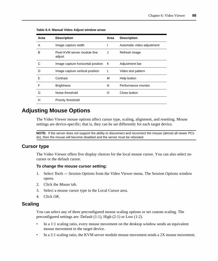
Chapter 6: Video Viewer 88
Adjusting Mouse OptionsThe Video Viewer mouse options affect cursor type, scaling, alignment, and resetting. Mouse settings are device-specific; that is, they can be set differently for each target device.
NOTE: If the server does not support the ability to disconnect and reconnect the mouse (almost all newer PCs do), then the mouse will become disabled and the server must be rebooted.
Cursor typeThe Video Viewer offers five display choices for the local mouse cursor. You can also select no cursor or the default cursor.
To change the mouse cursor setting:
1. Select Tools — Session Options from the Video Viewer menu. The Session Options window opens.
2. Click the Mouse tab.3. Select a mouse cursor type in the Local Cursor area.4. Click OK.
ScalingYou can select any of three preconfigured mouse scaling options or set custom scaling. The preconfigured settings are: Default (1:1), High (2:1) or Low (1:2).
• In a 1:1 scaling ratio, every mouse movement on the desktop window sends an equivalent mouse movement to the target device.
• In a 2:1 scaling ratio, the KVM server module mouse movement sends a 2X mouse movement.
Table 6.4: Manual Video Adjust window areas
Area Description Area Description
A Image capture width I Automatic video adjustment
B Pixel KVM server module fine adjust
J Refresh image
C Image capture horizontal position K Adjustment bar
D Image capture vertical position L Video test pattern
E Contrast M Help button
F Brightness N Performance monitor
G Noise threshold O Close button
H Priority threshold
Chapter 6: Video Viewer 89
• In a 1:2 scaling ratio, the value is 1/2X.
To set mouse scaling:
1. Select Tools — Session Options from the Video Viewer menu. The Session Options window opens.
2. Click the Mouse tab.3. To use one of the preconfigured settings, check the corresponding radio button in the Mouse
Scaling area.4. To set custom scaling, click the Custom radio button. The X and Y fields become enabled.
Type a mouse scaling value in the X and Y fields. For every mouse input, the mouse movements are multiplied by the corresponding X and Y scaling factors. Valid input ranges are 0.25 to 3.00.
Single cursor modeWhen single cursor mode is enabled, the Video Viewer title bar will show the keystroke that should be pressed to exit this mode.
To change the terminating keystroke for single cursor mode:
1. Select Tools — Session Options from the Video Viewer menu. The Session Options window opens.
2. Click the Mouse tab.3. Select the new terminating keystroke from the drop-down menu in the Single Cursor Mode
area.4. Click OK.
Adjusting General OptionsThe General tab in the Session Options window allows you to control Keyboard Pass-through in partial screen mode, Menu Activation Keystroke, and Background Refresh.
To adjust general options:
1. Select Tools — Session Options from the Video Viewer menu. The Session Options window opens.
2. Click the General tab.3. Select the Keyboard Pass-through checkbox to enable Keyboard Pass-through, or clear the
checkbox to disable Keyboard Pass-through. The Keyboard Pass-through checkbox is not selected by default. When Keyboard Pass-through is selected, all keystrokes except for Control-Alt-Delete are sent directly to the target device instead of the client computer.
4. Select a keystroke to use to activate the Video Viewer toolbar from the list in the Menu Activation Keystroke area.

Chapter 6: Video Viewer 90
5. If you want the Video Viewer to receive a constant stream of video data from the target device, select the Background Refresh checkbox. If you want the Video Viewer to receive data only when a change has occurred on the target device, clear the Background Refresh checkbox.
Adjusting The Video Viewer ToolbarYou may add up to 10 buttons to the toolbar. Use these buttons to provide access to defined function and keyboard macros. By default, the Align Local Cursor, Refresh Image and Single Cursor Mode buttons are visible on the toolbar.
To add buttons to the toolbar:
1. Select Tools — Session Options from the Video Viewer toolbar. The Session Options window opens.
2. Click the Toolbar tab.3. Select the items you want to add to the Video Viewer toolbar.4. Click OK.
Setting the Toolbar Hide Delay timeThe toolbar disappears when you remove the mouse cursor unless the Thumbtack button has been clicked. Change the interval between the removal of the mouse cursor and the disappearance of the toolbar by adjusting the Toolbar Hide Delay time.
To change the Toolbar Hide Delay time:
1. Select Tools — Session Options from the Video Viewer toolbar. The Session Options window opens.
2. Click the Toolbar tab.3. In the Toolbar Hide Delay field, type the number of seconds you want the toolbar to be visible
after the mouse cursor is removed.
— or —
Using the Up and Down buttons, click to increase or decrease the number of seconds you want the toolbar to be visible after the mouse cursor is removed.
4. Click OK to accept the changes and return to the Video Viewer.
Using Macros Use the Video Viewer macro function:
• To send a macro from a predefined macro group. Macro groups for Windows and Sun are already defined. Selecting from the available categories and keystrokes saves time and eliminates the risk of typographical errors.

Chapter 6: Video Viewer 91
• To change the macro group that is listed by default. This causes the macros in the specified group to be available in the Video Viewer Macros menu.
Macro group selections are device-specific. The macro group can be set differently for each target device.
Sending macrosTo send a macro, select Macros from the Video Viewer menu and choose a macro from the list.
Selecting the macro group to displaySelect the macro group applicable to the operating system of the target device.
To display macro groups in the Macros menu:
1. Select Macros — Display on Menu from the Video Viewer menu.2. Select the macro group to list on the Video Viewer Macro menu.3. The macro group you select will be displayed in the Video Viewer Macros menu the next time
you open the Macros menu.

92
CHAPTER
7 Virtual Media Guide
Virtual Media OverviewThe APC 2x1x16 Digital KVM switch (AP5610) supports virtual media when connected to an APC KVM USB VM server module. A USB media device can be attached to the KVM switch and made available to any target device connected to the KVM switch with a KVM USB VM server module. You can use virtual media to move data between a target device and USB media devices connected to the KVM switch. You can install, upgrade or recover the operating system, update the BIOS code or start the target device from a USB drive through the virtual media capabilities of the KVM switch.
Virtual media can be connected directly to the KVM switch using one of four USB ports on the KVM switch. In addition, virtual media can be connected to any remote workstation that is running Network Access Software and is connected to the KVM switch using an Ethernet connection. To open a virtual media session with a target device, the target device must first be connected to the KVM switch using a KVM USB VM server module.
Before You BeginVirtual media and USB 2.0 constraints
With virtual media, a user located at the KVM switch or using the remote software can access a local USB storage device, such as a USB CD drive, diskette drive or flash drive, from an attached computer.
The KVM USB VM server module is a composite device that addresses four functions: keyboard, mouse, CD drive and mass storage device. The USB CD drive and mass storage device are always present on the KVM switch, but you can only access them when a virtual media session is mapped. If a virtual media device is not mapped, the device is shown without media present. When a virtual media device is mapped to the target device, the target device will be notified that vitual media has been inserted. When the virtual media device is unmapped, the target device will be notified that virtual media was removed. The USB virtual media device is not disconnected from the target device.
The USB VM KVM server module presents the keyboard and mouse as a composite USB 2.0 device. Therefore, the BIOS of the connected computer must support composite USB 2.0 human
Chapter 7: Virtual Media Guide 93
interface device (HID). If the BIOS of the connected computer does not support this type of device, the keyboard and mouse might not work until the operating system loads USB 2.0 device drivers. Contact the computer manufacturer to determine whether a BIOS update exists that will provide support for a USB 2.0-connected keyboard and mouse.
Booting a computer using virtual memoryIn many cases the virtual media feature can boot an attached computer from a device attached to the USB port on the KVM switch. Most computers with a USB port can use virtual media; however, limitations in some USB media devices and the BIOS of some computers might prevent the computer from booting from a USB device attached to the KVM switch.
To boot a computer from a virtual USB device, the target device must support booting from an external composite USB device. This procedure also requires a CD of the operating system that supports external USB 2.0 booting.
To determine if your computer can be booted from virtual media:
1. Connect a USB CD drive to the KVM switch. Insert the installation CD for your operating system in the USB CD drive, then map the USB CD drive to the target device. Reboot the target device to determine if it will boot from this attached CD drive. The BIOS might need to be set to boot from an external USB device.
2. If the target device will not boot, connect the USB CD drive to a USB port on the target device and reboot the target device. If the target device successfully boots from the CD drive, the BIOS is not supporting booting from a composite USB 2.0 device. Check the support Web site from the target device manufacturer to determine if a BIOS update is available that supports booting from a composite USB 2.0 device. If so, update the BIOS and retry.
3. If the target device is not capable of booting from an external USB 2.0 device, try the following methods to remotely boot this target device:• Some BIOS versions provide an option to limit USB speeds. If this option is available to
you, change the USB port setting to “USB 1.1” or “Full Speed” mode and try booting again.
• Insert a USB 1.1 card and try booting again.• Insert a USB 1.1 Hub between the KVM USB VM server module and the target device
and try booting again.• Contact the manufacturer of the target device for information on availability of a BIOS
revision that will support booting from a composite USB 2.0 device.
Virtual media restrictionsThe KVM switches only support connection of USB 2.0 diskette drives, flash drives and CD drives. In addition, the Network Access Software only supports mapping of USB 2.0 and USB 1.1 diskette drives and flash drives connected to the client computer.

Chapter 7: Virtual Media Guide 94
Connecting Local Virtual MediaYou can connect virtual media directly to the KVM switch using the USB port on the KVM switch.
NOTE: All USB ports are assigned to a single virtual media session and cannot be independently mapped.
To start a local virtual media session:
1. Press Print Screen to start the OSD. The Main window opens.2. Connect the user to the target device with which you want to establish a virtual media session.
Use the arrow keys to highlight the target device name and then press Enter.3. Press Print Screen to start the OSD again.4. Click the VMedia button. The Virtual Media window opens. 5. Select one or more of the following checkboxes:
• Locked - Select this checkbox to specify that when the user is disconnected from a target device, the virtual media is also disconnected.
• Reserve - Select this checkbox to specify the virtual media connection can be accessed only by your user name and that no other user can connect to that target device. If both Locked and Reserved are selected, the session will be reserved.
• CD ROM - Select this checkbox to establish a virtual media CD connection to a target device. Clear this checkbox to end the connection.
• Mass Storage - Select this checkbox to establish a virtual media mass-storage connection to a target device. Clear this checkbox to end the connection.
• Write Access - Select this checkbox to enable the connected target device to write data to the virtual media during a virtual media session. Read access is always enabled during virtual media sessions.
6. Click OK.
Configuring Virtual Media RemotelyVirtual media can be configured using the web interface. Users can enable or disable virtual media on any server on a per KVM server module basis. This control is also maintained in the KVM switch after a power cycle.
Enabling/disabling virtual mediaThe web interface virtual media configuration screen displays the EID, name and connection path of each virtual media KVM server module, as well as a checkbox that controls whether virtual media is enabled or disabled for that individual KVM server module.
To enable or disable virtual media:
1. Click the Configure tab, then click Appliance- Virtual Media.
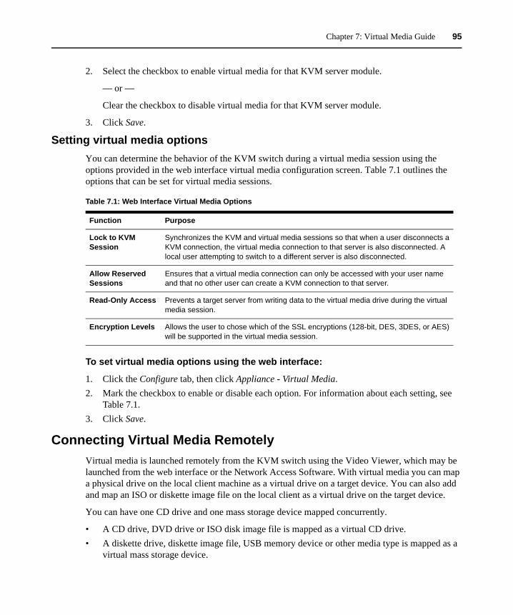
Chapter 7: Virtual Media Guide 95
2. Select the checkbox to enable virtual media for that KVM server module.
— or —
Clear the checkbox to disable virtual media for that KVM server module.
3. Click Save.
Setting virtual media optionsYou can determine the behavior of the KVM switch during a virtual media session using the options provided in the web interface virtual media configuration screen. Table 7.1 outlines the options that can be set for virtual media sessions.
To set virtual media options using the web interface:
1. Click the Configure tab, then click Appliance - Virtual Media.2. Mark the checkbox to enable or disable each option. For information about each setting, see
Table 7.1.3. Click Save.
Connecting Virtual Media RemotelyVirtual media is launched remotely from the KVM switch using the Video Viewer, which may be launched from the web interface or the Network Access Software. With virtual media you can map a physical drive on the local client machine as a virtual drive on a target device. You can also add and map an ISO or diskette image file on the local client as a virtual drive on the target device.
You can have one CD drive and one mass storage device mapped concurrently.
• A CD drive, DVD drive or ISO disk image file is mapped as a virtual CD drive.• A diskette drive, diskette image file, USB memory device or other media type is mapped as a
virtual mass storage device.
Table 7.1: Web Interface Virtual Media Options
Function Purpose
Lock to KVM Session
Synchronizes the KVM and virtual media sessions so that when a user disconnects a KVM connection, the virtual media connection to that server is also disconnected. A local user attempting to switch to a different server is also disconnected.
Allow Reserved Sessions
Ensures that a virtual media connection can only be accessed with your user name and that no other user can create a KVM connection to that server.
Read-Only Access Prevents a target server from writing data to the virtual media drive during the virtual media session.
Encryption Levels Allows the user to chose which of the SSL encryptions (128-bit, DES, 3DES, or AES) will be supported in the virtual media session.
Chapter 7: Virtual Media Guide 96
RequirementsVirtual media is supported on APC Digital KVM switches.
The target device must be connected to the KVM switch with a KVM USB VM server module.
The target device must support the types of USB2-compatible media that you virtually map. For example, the target device does not support a portable USB memory device, you cannot map the local device as a virtual media drive on the target device.
You (or the user group to which you belong) must have permission to establish virtual media sessions or reserved virtual media sessions to the target device.
An APC 2x1x16 Digital KVM switch (AP5610) or 2x1x32 Digital KVM switch (AP5615) will support up to three concurrent virtual media sessions. An 8x1x32 Digital KVM switch (AP5616) will support up to eight concurrent virtual media sessions. Only one virtual media session can be active to a target device at one time.
Sharing and preemption considerationsThe KVM and virtual media sessions are separate; therefore, there are many options for sharing, reserving or preempting sessions.
For example, the KVM and virtual media sessions can be locked together. In this mode, when a KVM session is disconnected, so is the associated virtual media session. If the sessions are not locked together, the KVM session can be closed but the virtual media session remains active.
After a target device has an active virtual media session without an associated active KVM session, either the original user (User A) can reconnect or a different user (User B) can connect to that channel. You can set an option in the Virtual Media window (Reserved) that lets only User A access the associated target device with a KVM session.
If User B has access to that KVM session (the Reserved option is not enabled), User B could control the media that is being used in the virtual media session. In some environments, this might not be desirable.
Virtual Media sessionsVirtual media window
Use the Virtual Media window to manage the mapping and unmapping of virtual media. The window displays all the physical drives on the client computer that can be mapped as virtual drives (non-USB hard drives are not available for mapping). You can also add ISO and diskette image files and then map them using the Virtual Media window.
After a target device is mapped, the Details View of the Virtual Media window displays information about the amount of data transferred and the time elapsed since the target device was mapped.

Chapter 7: Virtual Media Guide 97
You can specify that the virtual media session is reserved. When a session is reserved, and the associated KVM session is closed, another user cannot open a KVM session to that target device. If a session is not reserved, another KVM session can be opened. You can reserve the session to make sure that a critical update is not interrupted by another user attempting to preempt the KVM session or by inactivity time-outs on the KVM session.
You can also reset the KVM server module from the Virtual Media window. This action resets every form of USB media on the target device, and should be used with caution only when the target device is not responding.
Virtual media session settings
Virtual media session settings include locking, mapped drives access mode and encryption level. Table 7.2 lists and describes the virtual media session settings.
To open a virtual media session:
1. Open a Video Viewer session to the target device.2. From the Video Viewer toolbar, select Tools - Virtual Media. The Virtual Media window
opens.3. If you want to make this a reserved session, on the Virtual Media window click Details, then
select the Reserved checkbox.
To map a virtual media drive:
1. Open a virtual media session from the Video Viewer toolbar by selecting Tools - Virtual Media.
Table 7.2: Virtual media session settings
Setting Description
Locked The Locked setting specifies whether a virtual media session is locked to the KVM session on the target device. When locking is enabled (which is the default) and the KVM session is closed, the virtual media session also closes. When locking is disabled and the KVM session is closed, the virtual media session remains active.
Mapped drives access mode
You can set the access mode for mapped drives to read-only. When the access mode is read-only, you cannot write data to the mapped drive on the client computer. When the access mode is not set as read-only, you can read and write data from or to the mapped drive.If the mapped drive is read-only by design (for example, certain CD drives, DVD drives, or ISO images), the configured read-write access mode is ignored.Setting the read-only mode can be helpful when a read-write drive such as a mass storage device or a USB removable media is mapped, and you want to prevent the user from writing data to it.
Encryption level
You can configure up to three encryption levels for virtual media sessions. Any combination is valid. The choices are: DES, 3DES and 128-bit SSL. The highest level selected is used. The default is no encryption (no encryption levels selected).

Chapter 7: Virtual Media Guide 98
2. To map a physical drive as a virtual media drive, complete the following steps:a. In the Virtual Media window, select the Mapped checkbox next to the drive or drives you
want to map. b. To limit the mapped drive to read-only access, select the Read Only checkbox next to the
drive prior to mapping the drive. If the virtual media session settings were previously configured so that all mapped drives must be read-only, this checkbox is already enabled and cannot be changed.
Select the Read Only checkbox if the session settings enabled read and write access, but you want to limit the access of a particular drive to read-only.
3. To add and map an ISO or diskette image as a virtual media drive, complete the following steps:a. In the Virtual Media window, click Add Image.b. The Common File Chooser window opens and displays the directory containing disk
image files (ending in .iso or .img). Select an ISO or diskette image file and click Open.c. The file header is checked to make sure it is correct. If it is, the Common File Chooser
window closes and the chosen image file opens in the Virtual Media window, where it can be mapped by selecting the Mapped checkbox.
d. Repeat steps a through c for all ISO or diskette images you want to add. You can add any number of image files (up to the limits imposed by memory), but you can only have one virtual CD or virtual mass storage device mapped concurrently.
If you attempt to map too many drives (one CD and one mass storage device) or too many drives of a particular type (more than one CD or mass storage device), a message is displayed. If you still want to map a new drive, you must first unmap an existing mapped drive, then map the new drive.
After a physical drive or image is mapped, it can be used on the target device.
To unmap a virtual media drive:
1. Eject the mapped drive from the target device.2. In the virutal media window, clear the mapped checkbox.
To display virtual media drive details:
1. In the Virtual Media window, click Details. The window expands to display the Details table. Each row provides the following information about the virtual media drive:• Target Drive - Name used for the mapped drive, such as Virtual CD 1. • Mapped to - Identical to Drive information listed in the Client View Drive column.• Read Bytes and Write Bytes - Amount of data transferred since the mapping.• Duration - Elapsed time since the drive was mapped.
2. To close the Details view, click Details again.
Chapter 7: Virtual Media Guide 99
Resetting USB media devices
NOTE: The USB reset feature resets every USB device on the target device, including the mouse and keyboard. It should only be used when the target device is not responding.
1. In the Virtual Media window, click Details.2. Click USB Reset.3. A warning message indicates the possible effects of the reset. Click Yes to confirm the reset or
No to cancel the reset.4. To close the Details view, click Details again.
Closing a virtual media session1. Click Exit or X to close the window.2. If you have any mapped drives, a message indicates the drives will be unmapped. Click Yes to
confirm and close the window or click No to cancel the close.
If you attempt to disconnect an active KVM session that has an associated locked virtual media session, a confirmation message indicates that any virtual media mappings will be lost.

100
CHAPTER
8 Configuring LDAP
LDAP is a vendor-independent protocol standard used for accessing, querying and updating a directory using TCP/IP. Based on the X.500 Directory Services model, LDAP is a global directory structure that supports strong security features including authentication, privacy and integrity.
LDAP Authentication Configuration ParametersIf individual user accounts are stored on an LDAP-enabled directory service, such as Active Directory, you can use the directory service to authenticate users.
The default values given for the LDAP search and query parameters are defined for use with Active Directory.
The settings made in the Authentication subcategory of the Configure tab let you configure your authentication configuration parameters. The software sends the Network Access Software user name, password and other information to the KVM switch, which then determines whether the Network Access Software user has permission to view or change configuration parameters for the KVM switch in the web interface.
NOTE: The LDAP default values should be used unless specified otherwise or Active Directory has been reconfigured. Modifying the default values may cause LDAP authentication server communication errors.
LDAP parametersClicking the Authentication tab in the Appliance subcategory of the Configure tab displays the parameters that define LDAP server connection information.
LDAP authentication priority
You can disable LDAP, or you can set the authentication priority by choosing whether local authentication or LDAP authentication should happen first.

Chapter 8: Configuring LDAP 101
To configure LDAP authentication priority parameters:
1. Select Configure — Appliance — Authentication — Authentication Settings. 2. Select either Use Local Authentication, Use LDAP Authentication, Use Local First or Use
LDAP First. 3. Click Save.
LDAP server parametersThe IP Address fields specify the host names or IP addresses of the primary and secondary LDAP servers. The second LDAP server is optional.
The Port ID fields specify the User Datagram Protocol (UDP) port numbers used to communicate with the LDAP servers. The default is 389 for non-secure LDAP and 636 for secure LDAP. The default Port ID is automatically entered by the software when an access type is specified.
NOTE: The Access Type radio buttons specify how a query is sent to each LDAP target device. You may choose either LDAP or LDAPS. Choose LDAP to send all user names, passwords and other information as a non-secure clear text between a KVM switch and LDAP server. Choose LDAPS for secure, encrypted communication using a secure sockets layer (SSL).
To configure LDAP server parameters:
1. Select Appliance — Authentication — Server. 2. Identify the primary and secondary server addresses, port and access type in the appropriate
fields or radio buttons. 3. Click Save.
LDAP search parametersClicking the Search tab displays the parameters used when searching for LDAP directory service users.
Use the Search DN field to define an administrator-level user that the KVM switch uses to log into the directory service. Once the KVM switch is authenticated, the directory service grants it access to the directory to perform the user authentication queries specified on the Query tab. The default values are cn=Administrator, cn=Users, dc=yourDomainName and dc=com and may be modified. For example, to define an administrator Distinguished Name (DN) for test.view.com, type cn=Administrator, cn=Users, dc=test, dc=view and dc=com. This is a required field unless the directory service has been configured to enable anonymous search, which is not the default.
Each Search DN value must be separated by a comma. The Search Password field is used to authenticate the administrator or user specified in the Search DN field.
Use the Search Base field to define a starting point from which LDAP searches begin. The default values are dc=yourDomainName, dc=com and may be modified. For example, to define a search base for test.com, type dc=test, dc=com. Each Search Base value must be separated by a comma.

Chapter 8: Configuring LDAP 102
The UID Mask field specifies the search criteria for User ID searches of LDAP target devices. The format should be in the form <name>=<%1>. The default value is KVM server moduleAccountName=%1, which is correct for use with Active Directory. This field is required for LDAP searches.
To configure LDAP search parameters:
1. Select Appliance — Authentication — Search. 2. Enter the appropriate information in the Search DN, Search Password, Search Base and UID
Mask fields. 3. Click Save.
LDAP query parametersClicking the Query Parameters tab displays the parameters used when performing user authentication queries.
The KVM switch performs two different types of queries. Appliance query mode is used to authenticate administrators attempting to access the KVM switch itself. Server query mode is used to authenticate users attempting to access attached target devices.
Additionally, each type of query has three modes that utilize information you configure in the Query tab to determine whether a Network Access Software user has access to a KVM switch or to connected target devices.
Configure the following settings in the Query tab:
• The Appliance Query Mode determines whether a Network Access Software user has access to the KVM switch.
• The Server Query Mode determines whether a Network Access Software user has user access to target devices connected to a KVM switch. The user does not have access to the KVM switch.
• The Group Container, Group Container Mask and Target Mask fields are only used for group query modes and are required when performing a KVM switch or device query.
• The Group Container field specifies the organizational unit (ou) created in Active Directory by the administrator as the location for group objects. Group objects are Active Directory objects that can contain users, computers, contacts and other groups. Group Container is used when Query Mode is set to Group. Each group object is assigned members to associate with a particular access level for member objects (people, KVM switches and target devices). The access level associated with a group is configured by setting the value of an attribute in the group object. For example, if the Notes property in the group object is used to implement the access control attribute, the Access Control Attribute field in the Query tab should be set to info. Setting the Notes property to KVM User Admin causes the members of that group to have user administration access to the KVM switches and target devices that are also members of that KVM server module group.

Chapter 8: Configuring LDAP 103
• The Notes property is used to implement the access control attribute. The value of the Notes property, available in group and user objects shown in Active Directory Users and Computers (ADUC), is stored internally in the directory, in the value of the info attribute. ADUC is a Microsoft Management Console snap-in for configuring Active Directory. It is started by selecting Start > Programs > Administrative Tools > Active Directory Users and Computers. This tool is used to create, configure and delete objects such as users, computers and groups.
• The Group Container Mask field defines the object type of the Group Container, which is normally an organizational unit. The default value is “ou=%1”.
• The Target Mask field defines a search filter for the target device. The default value is “cn=%1”.
• The Access Control Attribute field specifies the name of the attribute that is used when the query modes are set to Attribute. The default value is info.
KVM switch and target device query modes
One of three modes can each be used for Query Mode (Appliance) and Query Mode (Server):
• Basic – A user name and password query for the Network Access Software user is made to the directory service. If they are verified, the Network Access Software user is given administrator access to the KVM switch and any attached target devices for Query Mode (Appliance), or to any selected target device for Query Mode (Server).
• Attribute – A user name, password and Access Control Attribute query for the KVM switch user is made to the directory service. The Access Control Attribute is read from the user object (the user account) in Active Directory.
If the value “Administrator” is found, the Network Access Software user is given KVM switch administrator access to the KVM switch and any attached target devices for Query Mode (Appliance), or to any selected target device for Query Mode (Server). If the value “Device User” is found, the Network Access Software user is given User administrator access to the KVM switch and attached target devices for Query Mode (appliance), or to any selected target device for Query Mode (Server).
• Group – A user name, password, and group query is made to the directory service for an appliance and attached target devices when using Query Mode (Appliance), or for a selected target device when using Query Mode (Server). If a group is found containing the user and the appliance name, the Network Access Software user is given access to the appliance or attached target devices, depending on the group contents, when using Query Mode (Appliance). If a group is found containing the user and target device IDs, the Network Access Software user is given access to the selected target device connected to the appliance when using Query Mode (Server).
Groups can be nested to a maximum of 16 levels in depth. Use nesting to create groups within other groups. For example, you may have a top-level group named Computers that contains a member named R&D, which is a group. The R&D group may contain a member named Domestic, which is a group, and so on.

Chapter 8: Configuring LDAP 104
To configure LDAP query parameters:
1. Select Appliance — Authentication — Query. 2. Select Basic, User Attribute or Group Attribute for the Appliance Query Mode and the Server
Query Mode. 3. Enter the appropriate information in the Group Container, Group Container Mask, Target Mask
and Access Control attribute fields. 4. Click Save.
NOTE: These options cannot be changed if the LDAP Priority is set to LDAP Disabled on the Overview screen.
Setting up Active Directory for performing queries
Before you can use any of the querying modes for units, you must first make changes to Active Directory so that the selected querying mode can assign the applicable authorization level for the Network Access Software user.
To set up group queries:
1. Log into Windows with administrator privileges.2. Open Active Directory software.3. Create an organizational unit to be used as a group container.4. Create an object in Active Directory with a name identical to the switching system name for
querying KVM switches (specified in the Name field in the SNMP category of the Configure tab), or identical to the attached target devices for querying servers (specified in the Servers category). The name must match exactly and is case-sensitive.
5. The KVM switch names and server names used for group queries are stored in the KVM switch. The KVM switch name and server names specified in the SNMP and Servers categories must identically match the object names in Active Directory. Each KVM switch name and target device name may be comprised of any combination of upper-case and lower-case letters (a-z, A-Z), digits (0-9) and hyphens (-). You cannot use spaces and periods (.) or create a name that consists entirely of digits.
6. Create one or more groups under the organizational unit you created in step 3.7. Add the user names and server and KVM switch objects to the groups you created in Step 5.8. Specify the value of any attribute being used to implement the access control attribute. For
example, if you are using info as the attribute in the Access Control Attribute field and using the Notes property in the group object to implement the access control attribute, the value of the Notes attribute in Active Directory may be set to one of the three available access levels (Device User, Administrator, or Read-Only User) for the group object. The members of the group may then access the KVM switches and servers at the specified access level.
105
Appendix A: Flash UpgradesYou can use the APC KVM switch flash upgrade feature to update the KVM switch with the latest firmware available. This update can be performed using the Network Access Software or using a Trivial File Transfer Protocol (TFTP) target device.
After the flash memory is reprogrammed with the upgrade, the KVM switch performs a soft reset, which terminates all KVM server module sessions. A target device experiencing a KVM server module firmware update might not be visible or might be listed as disconnected. The target device opens normally when the flash update is completed. During an OSD initiated upgrade, the KVM server module status indicator in the OSD Main window is yellow.
To upgrade the KVM switch firmware using the web interface:
1. Go to http://www.apc.com/tools/download and download the latest flash firmware. Save the flash upgrade file to the correct directory on the TFTP target device.
2. Connect a computer running terminal emulation software to the configuration port on the rear panel of the KVM switch using a straight serial cable. The terminal should be set to 9600 bps, 8 bits, 1 stop bit, no parity and no flow control.
3. Tun on the KVM switch. After approximately one minute, press any key to access the Console Main menu.
4. The Console Main menu opens. Select the Firmware Management option. The current version of the firmware is opened on the Firmware Management menu.
5. Type 1 and press Enter to select FLASH Download.6. Type the IP address of the TFTP target device and press Enter.7. Type the name of the flash file and press Enter.8. Confirm the TFTP download by typing a y or yes and pressing Enter.9. The KVM switch will verify the file you downloaded is valid. Next, you are prompted to
confirm the upgrade. Type a y or yes and press Enter to confirm.10. The KVM switch begins the flash upgrade process. On-screen indicators show the upgrade
progress. After the upload is complete, the KVM switch resets and upgrades the internal subsystems.
11. After the upgrade is complete, a verification message is displayed.
Repairing damaged firmwareIf the firmware is damaged after a firmware upgrade (for example, if the KVM switch is turned off and turned on during the upgrade process), the KVM switch will remain in boot mode. In this mode, the Power LED at the rear panel flashes at about 1 Hz, and the KVM switch attempts to restore the firmware over TFTP using the following default configuration:
• TFTP client IP address 10.0.0.2
APPENDICES
106
• TFTP target device IP address 10.0.0.3• Upgrade file name equal to CMN-XXXX.fl, where XXXX is the 4-digit Compliance Model
Number (CMN) that is printed on the agency label of the KVM switch
To repair damaged firmware:
1. Connect the KVM switch to the TFTP target device using a cross-over cable or hub. The TFTP target device must be set up with the default IP address (10.0.0.3).
2. Rename the upgrade file to the default file name (CMN-XXXX.fl).
The Power LED will flash at about 2 Hz when the KVM switch is downloading the upgrade file, and it will flash at about 4 Hz when it is programming the downloaded file to flash. After it has restored the firmware, the KVM switch reboots automatically and the Power LED is lit.
Updating Network Access SoftwareFor optimal operation of the switching system, make sure that you have the latest version of Network Access Software available from the APC Web site.
To update Network Access Software:
1. Go to http://www.apc.com/tools/download and download the update file.2. Double-click on the installer. The installer determines if a previous version of the software
resides on the computer.3. If no previous version has been detected and a window opens to confirm the upgrade, click
Continue.— or — If a previous version is detected and a window opens alerting you to another version of the product, click Overwrite to confirm the upgrade.— or —Click Cancel to exit without upgrading the software.
4. Installation starts. The Program Files, Shortcuts, Environment Variables, and the Registry Entries (for Windows operating systems) are installed or overwritten with the new files and settings of the current version.

107
Appendix B: UTP CablingThe performance of a switching system depends on high quality connections. Poor quality or poorly installed or maintained cabling can diminish system performance. Consult with the local code officials orAPC technical support prior to any installation.
UTP copper cablingSwitching systems utilize unshielded twisted pair (UTP) cabling. The KVM switch supports three types of UTP cabling:
• CAT5 UTP (4-pair) high performance cable consists of twisted pair conductors, used primarily for data transmission. The twisting of the pairs gives this cable some immunity from the infiltration of unwanted interference. CAT5 cable is generally used for networks running at 100 or 1000 Mbps.
• CAT5E (enhanced) cable has the same characteristics as CAT5 cable but is manufactured to higher standards.
• CAT6 cable is manufactured to higher standards than CAT5E cable. CAT6 has higher measured frequency ranges and significantly better performance requirements than CAT5E cable at the KVM server module frequencies.
Wiring standardsThere are two supported wiring standards for 8-conductor (4-pair) RJ-45 terminated UTP cable: EIA/TIA 568A and EA/TIA 568B. These standards apply to installations utilizing CAT5, CAT5E, and CAT6 cable specifications. The switching system supports either of these wiring standards. See Table B.1 for details.
Table B.1: UTP wiring standards
Pin EIA/TIA 568A EIA/TIA 568B
1 white/green white/orange
2 green orange
3 white/orange white/green
4 blue blue
5 white/blue white/blue
6 orange green
7 white/brown white/brown
8 brown brown

108
Cabling installation, maintenance and safety tipsReview the following important safety considerations before installing or maintaining the cables:
• Maintain the twists of the pairs all the way to the point of termination or leave no more that one-half inch of cable untwisted. Do not remove more than one inch of jacket while terminating the cable.
• If bending the cable is necessary, make it gradual with no bend sharper than a one-inch radius. Sharply bending the cable can permanently damage the interior of the cable.
• Arrange the cables neatly with cable ties, using low to moderate pressure. Do not over tighten ties.
• Where necessary, cross connect the cables using rated punch blocks, patch panels, and components. Do not splice or bridge cables at any point.
• Keep the CAT5 cable as far away as possible from potential sources of electromagnetic interference (EMI), such as electrical cables, transformers and light fixtures. Do not tie cables to electrical conduits or lay cables on electrical fixtures.
• Always test every installed segment with a cable tester. Toning alone is not an acceptable test.
• Always install jacks to prevent dust and other contaminants from settling on the contacts. The contacts of the jack should face up on the flush mounted plates, or left, right, or down on surface mount boxes.
• Always leave extra slack in the cables, neatly coiled in the ceiling or nearest concealed location. Leave at least five feet at the work outlet side and 10 feet at the patch panel side.
• Choose either EIA/TIA 568A or EA/TIA 568B wiring standard before beginning. Wire all jacks and patch panels for the KVM server module wiring scheme. Do not mix EIA/TIA 568A and EA/TIA 568B wiring in the KVM server module installation.
• Always follow all local and national fire and building codes. Be sure to firestop all cables that penetrate a firewall. Use plenum rated cable where it is required.

109
Appendix C: Keyboard And Mouse ShortcutsThis appendix lists the keyboard and mouse shortcuts that can be used in the Network Access Software.
Table C.1: Divider pane keyboard and mouse shortcuts
Operation Description
F6 Navigates between the split-screens and gives focus to the last element that had focus.
F8 Gives focus to the divider.
Left or Up Arrow Moves the divider left if the divider has the focus.
Right or Down Arrow Moves the divider right if the divider has the focus.
Home Gives the right pane of the split-screen all of the area (left pane is hidden) if the divider has the focus.
End Gives the left pane of the split-screen all of the area (right pane is hidden) if the divider has the focus.
Click + Mouse Drag Moves the divider left or right.
Table C.2: Tree view control: keyboard and mouse shortcuts
Operation Description
Mouse Single-click Deselects the current focus point and selects the node the mouse pointer is over.
Enter Toggles between the expand and collapse state of an expandable node (a node with sublevels). Does nothing on a leaf node (a node with no sublevels).
Up Arrow Deselects the current focus point and selects the next node above the current focus point.
Down Arrow Deselects the current focus point and selects the next node below the current focus point.
Spacebar Alternately selects and deselects the node that currently has the focus.
Enter Alternately collapses and expands the node that has focus. Only applies to nodes that have sublevels. Does nothing if a node has no sublevels.
Home Deselects the current focus point and selects the root node.
End Deselects the current focus point and selects the last node visible in the tree.
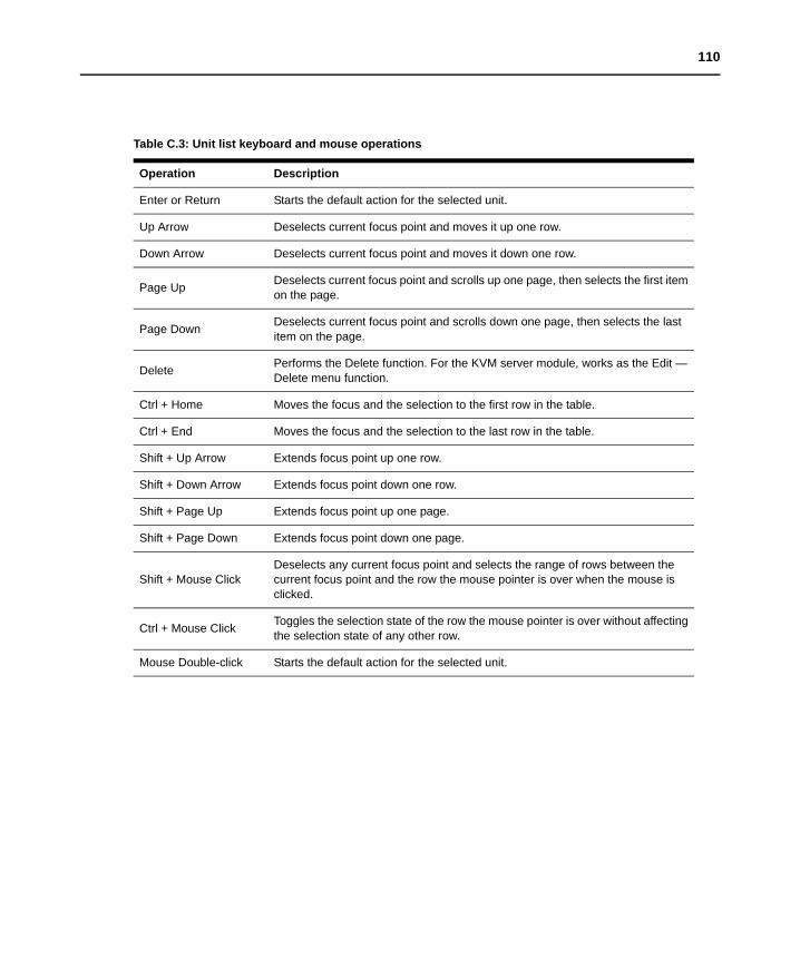
110
Table C.3: Unit list keyboard and mouse operations
Operation Description
Enter or Return Starts the default action for the selected unit.
Up Arrow Deselects current focus point and moves it up one row.
Down Arrow Deselects current focus point and moves it down one row.
Page Up Deselects current focus point and scrolls up one page, then selects the first item on the page.
Page Down Deselects current focus point and scrolls down one page, then selects the last item on the page.
Delete Performs the Delete function. For the KVM server module, works as the Edit — Delete menu function.
Ctrl + Home Moves the focus and the selection to the first row in the table.
Ctrl + End Moves the focus and the selection to the last row in the table.
Shift + Up Arrow Extends focus point up one row.
Shift + Down Arrow Extends focus point down one row.
Shift + Page Up Extends focus point up one page.
Shift + Page Down Extends focus point down one page.
Shift + Mouse ClickDeselects any current focus point and selects the range of rows between the current focus point and the row the mouse pointer is over when the mouse is clicked.
Ctrl + Mouse Click Toggles the selection state of the row the mouse pointer is over without affecting the selection state of any other row.
Mouse Double-click Starts the default action for the selected unit.

111
Appendix D: Sun Advanced Key EmulationCertain keys on a standard Type 5 (US) Sun keyboard may be emulated by key press sequences on a PS/2 keyboard. To enable Advanced Sun Key Emulation mode and use the keys, press and hold Ctrl+Shift+Alt and then press the Scroll Lock key. The Scroll Lock LED blinks. Use the indicated key in the following table as you would use the advanced keys on a Sun keyboard.
Table D.1: Sun Key Emulation
Sun Key (US) PS/2 Key Combination
Compose Application (*)
Compose keypad *
Power F11
Open F7
Help Num Lock
Props F3
Front F5
Stop F1
Again F2
Undo F4
Cut F10
Copy F6
Paste F8
Find F9
Mute keypad /
Vol + keypad +
Vol - keypad -
Command (left) (**) F12
Command (left) (**) Win (GUI) left (*)
Command (right) (**) Win (GUI) right (*)
(*) Windows 95 104-key keyboard(**) The Command key is the Sun Meta (diamond key)

112
For example: For Stop + A, press and hold Ctrl+Shift+Alt and press Scroll Lock, then F1+A.
These key combinations will work with the USB KVM server module adaptor (if your Sun system comes with a USB port) as well as the Sun KVM server module adaptor. With the exception of F12, these key combinations are not recognized by Microsoft Windows. Using F12 performs a Windows key press.

113
Appendix E: Ports Used By The SoftwareTable E.1 lists the port numbers that the software uses to communicate with certain KVM switches. This information can be used to configure firewalls to let Network Access Software operate in the networks.
Table E.1: Ports Used by Network Access Software
Port Number KVM switch Type Purpose
3211 APC 2x1x16 Digital APC 2x1x32 Digital APC 8x1x32 Digital
TCP Proprietary management protocol
3211 APC 2x1x16 Digital APC 2x1x32 Digital APC 8x1x32 Digital
UDP Proprietary installation and discovery protocol
2068 APC 2x1x16 Digital APC 2x1x32 Digital APC 8x1x32 Digital
TCP Encrypted keyboard and mouse data
2068 APC 2x1x16 Digital APC 2x1x32 Digital APC 8x1x32 Digital
TCP Digitized video data
2068 APC 2x1x16 Digital APC 2x1x32 Digital APC 8x1x32 Digital
TCP Virtual media
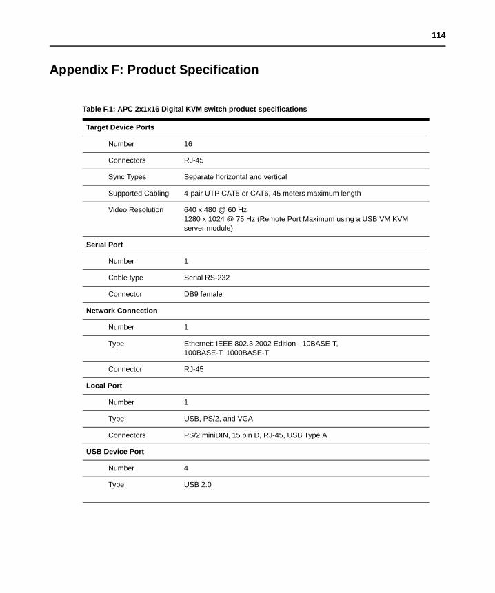
114
Appendix F: Product Specification
Table F.1: APC 2x1x16 Digital KVM switch product specifications
Target Device Ports
Number 16
Connectors RJ-45
Sync Types Separate horizontal and vertical
Supported Cabling 4-pair UTP CAT5 or CAT6, 45 meters maximum length
Video Resolution 640 x 480 @ 60 Hz1280 x 1024 @ 75 Hz (Remote Port Maximum using a USB VM KVM server module)
Serial Port
Number 1
Cable type Serial RS-232
Connector DB9 female
Network Connection
Number 1
Type Ethernet: IEEE 802.3 2002 Edition - 10BASE-T, 100BASE-T, 1000BASE-T
Connector RJ-45
Local Port
Number 1
Type USB, PS/2, and VGA
Connectors PS/2 miniDIN, 15 pin D, RJ-45, USB Type A
USB Device Port
Number 4
Type USB 2.0
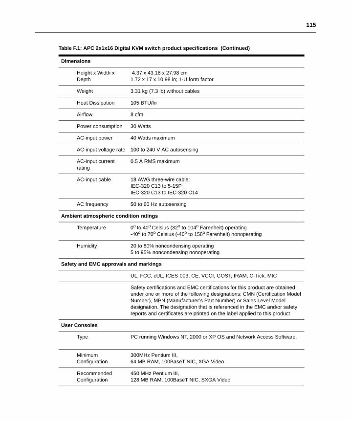
115
Dimensions
Height x Width x Depth
4.37 x 43.18 x 27.98 cm 1.72 x 17 x 10.98 in; 1-U form factor
Weight 3.31 kg (7.3 lb) without cables
Heat Dissipation 105 BTU/hr
Airflow 8 cfm
Power consumption 30 Watts
AC-input power 40 Watts maximum
AC-input voltage rate 100 to 240 V AC autosensing
AC-input current rating
0.5 A RMS maximum
AC-input cable 18 AWG three-wire cable:IEC-320 C13 to 5-15PIEC-320 C13 to IEC-320 C14
AC frequency 50 to 60 Hz autosensing
Ambient atmospheric condition ratings
Temperature 0o to 40o Celsius (32o to 104o Farenheit) operating -40o to 70o Celsius (-40o to 158o Farenheit) nonoperating
Humidity 20 to 80% noncondensing operating 5 to 95% noncondensing nonoperating
Safety and EMC approvals and markings
UL, FCC, cUL, ICES-003, CE, VCCI, GOST, IRAM, C-Tick, MIC
Safety certifications and EMC certifications for this product are obtained under one or more of the following designations: CMN (Certification Model Number), MPN (Manufacturer’s Part Number) or Sales Level Model designation. The designation that is referenced in the EMC and/or safety reports and certificates are printed on the label applied to this product
User Consoles
Type PC running Windows NT, 2000 or XP OS and Network Access Software.
Minimum Configuration
300MHz Pentium III,64 MB RAM, 100BaseT NIC, XGA Video
Recommended Configuration
450 MHz Pentium III, 128 MB RAM, 100BaseT NIC, SXGA Video
Table F.1: APC 2x1x16 Digital KVM switch product specifications (Continued)

116
Table F.2: APC 2x1x32 and 8x1x32 KVM switch product specifications
Target Device Ports
Number 32
Connectors RJ-45
Sync Types Separate horizontal and vertical
Supported Cabling 4-pair UTP CAT5 or CAT6, 45 meters maximum length
Video Resolution640 x 480 @ 60 Hz1280 x 1024 @ 75 Hz (Remote Port Maximum using a USB VM KVM server module)
Serial Port
Number 1
Cable type Serial RS-232
Connector DB9 female
Network Connection
Number 1
Type Ethernet: IEEE 802.3 2002 Edition - 10BASE-T, 100BASE-T, 1000BASE-T
Connector RJ-45
Local Port
Number 1
Type USB, PS/2, and VGA
Connectors PS/2 miniDIN, 15 pin D, RJ-45, USB Type A
USB Device Port
Number 4
Type USB 2.0
Dimensions
Height x Width x Depth
4.37 x 43.18 x 35.75 cm1.72 x 17 x 14.08 in; 1-U form factor
Weight 4.5 kg (10 lb) without cables
Heat Dissipation 105 BTU/hr
Airflow 8 cfm
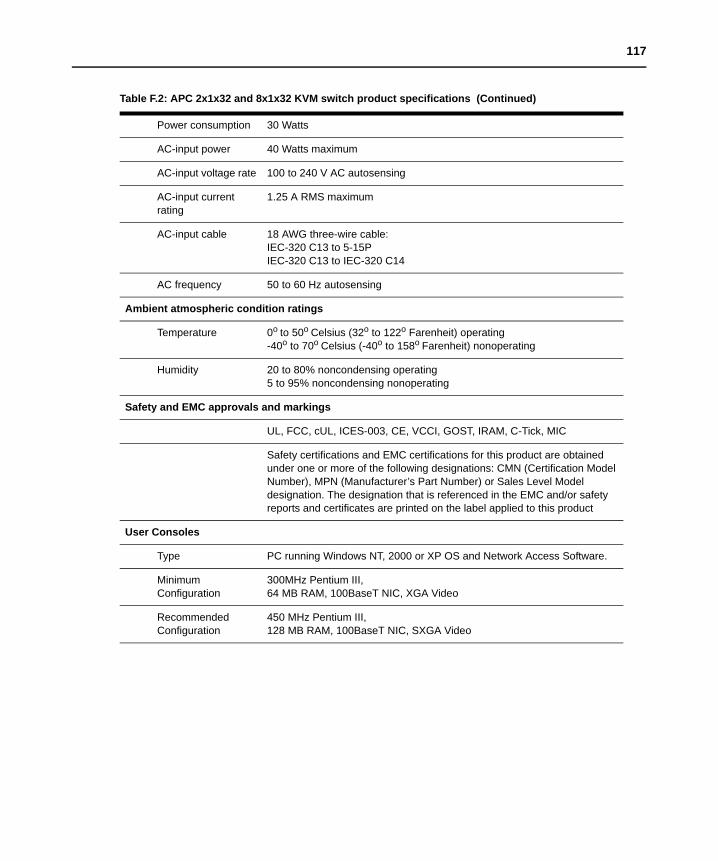
117
Power consumption 30 Watts
AC-input power 40 Watts maximum
AC-input voltage rate 100 to 240 V AC autosensing
AC-input current rating
1.25 A RMS maximum
AC-input cable 18 AWG three-wire cable:IEC-320 C13 to 5-15PIEC-320 C13 to IEC-320 C14
AC frequency 50 to 60 Hz autosensing
Ambient atmospheric condition ratings
Temperature 0o to 50o Celsius (32o to 122o Farenheit) operating -40o to 70o Celsius (-40o to 158o Farenheit) nonoperating
Humidity 20 to 80% noncondensing operating 5 to 95% noncondensing nonoperating
Safety and EMC approvals and markings
UL, FCC, cUL, ICES-003, CE, VCCI, GOST, IRAM, C-Tick, MIC
Safety certifications and EMC certifications for this product are obtained under one or more of the following designations: CMN (Certification Model Number), MPN (Manufacturer’s Part Number) or Sales Level Model designation. The designation that is referenced in the EMC and/or safety reports and certificates are printed on the label applied to this product
User Consoles
Type PC running Windows NT, 2000 or XP OS and Network Access Software.
Minimum Configuration
300MHz Pentium III,64 MB RAM, 100BaseT NIC, XGA Video
Recommended Configuration
450 MHz Pentium III, 128 MB RAM, 100BaseT NIC, SXGA Video
Table F.2: APC 2x1x32 and 8x1x32 KVM switch product specifications (Continued)

118
Appendix G: Getting Help And Technical AssistanceFor service or technical assistance or for more information about APC products, contact APC at a number on the APC Web site, www.apc.com/support
Troubleshooting• Check all cables to make sure they are connected.• Check the power switches to make sure the system and any optional devices are turned on.• Use the troubleshooting information in your system documentation and use the diagnostic
tools that came with your system.• Go to the APC support Web site at http://www.apc.com to check for technical information,
hints, tips and new device drivers or to submit a request for information.
Using the documentationInformation about your APC software is available in the documentation that comes with the product. That documentation can include printed documents, online documents, readme files and help files. See the troubleshooting information in your system documentation for instructions for using the diagnostic programs.

119
Appendix H: NoticesTrademarks
Intel, MMX, and Pentium are trademarks of Intel Corporation in the United States, other countries, or both.
Microsoft, Windows, Internet Explorer and Windows NT are trademarks of Microsoft Corporation in the United States, other countries, or both.
UNIX is a registered trademark of The Open Group in the United States and other countries.
Java and all Java-based trademarks and logos are trademarks of Sun Microsystems, Inc. in the United States, other countries, or both.
Adaptec and HostRAID are trademarks of Adaptec, Inc., in the United States, other countries, or both.
Linux is a trademark of Linus Torvalds in the United States, other countries, or both.
Red Hat, the Red Hat “Shadow Man” logo, and all Red Hat-based trademarks and logos are trademarks or registered trademarks of Red Hat, Inc., in the United States and other countries.
Other company, product, or service names may be trademarks or service marks of others.

USA Notification
Warning: Changes or modifications to this unit not expressly approved by the party responsible for compliance could void the user’s authority to operate the equipment.
Note: This equipment has been tested and found to comply with the limits for a Class A digital device, pursuant to Part 15 of the FCC Rules. These limits are designed to provide reasonable protection against harmful interference when the equipment is operated in a commercial environment. This equipment generates, uses and can radiate radio frequency energy and, if not installed and used in accordance with the instruction manual, may cause harmful interference to radio communications. Operation of this equipment is a residential area is likely to cause harmful interference, in which case the user will be required to correct the interference at his/her own expense.
Canadian Notification
This Class A digital apparatus complies with Canadian ICES-003.
Cet appareil numérique de la classe A est conforme à la norme NMB-003 du Canada.
Japanese Notification
Korean Notification

Installer/User GuideFor Technical Support:
www.apc.com
APC: 990-3256A590-800-501C
Digital KVM SwitchesAP5610, AP5615 and AP5616