digital hd tv antenna installation guide · digital hd tv antenna installation guide channels 6 -...
TRANSCRIPT
DIGITAL HD TV ANTENNA
INSTALLATION GUIDE
CHANNELS 6 - 12VHF
CHANNELS 28 - 38UHF+
DESIGNED FOR DIGITAL TVFull HD
10803D
AA1300
FOR METRO + OUTER AREAS
FRINGE
Thank you for choosing the Antsig range of quality audio video equipment.
The D-MAX Range of antenna have been designed and tested in Australia using a state-of-the-art Anechoic Chamber. This ensures that your antenna has been optimised to capture high definition digital TV signals.
Successful antenna installation requires strong collection of the TV signal and distribution of the TV signal.Follow these key guidelines for proper installation:
• Note your position to transmitter towers • Use RG6 quad cable for installation • Mount antenna high as possible with fewest • Terminate with F-connectors obstructions in line of sight with transmitter • Keep cable lengths to a minimum
If, at any time, you are unsure about performing any functions relating to antenna installation, please contact a professional installer.
2
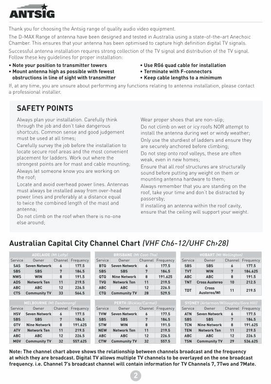
Note: The channel chart above shows the relationship between channels broadcast and the frequency at which they are broadcast. Digital TV allows multiple TV channels to be overlayed on the one broadcast frequency. i.e. Channel 7’s broadcast channel will contain information for TV Channels 7, 7Two and 7Mate.
Always plan your installation. Carefully think through the job and don’t take dangerous shortcuts. Common sense and good judgement must be used at all times;Carefully survey the job before the installation to locate secure roof areas and the most convenient placement for ladders. Work out where the strongest points are for mast and cable mounting;Always let someone know you are working on the roof;Locate and avoid overhead power lines. Antennas must always be installed away from over-head power lines and preferably at a distance equal to twice the combined length of the mast and antenna;Do not climb on the roof when there is no-one else around;
Wear proper shoes that are non-slip;Do not climb on wet or icy roofs NOR attempt to install the antenna during wet or windy weather;Only use the sturdiest of ladders and ensure they are securely anchored before climbing;Do not step onto roof valleys, these are often weak, even in new homes;Ensure that all roof structures are structurally sound before putting any weight on them or mounting antenna hardware to them;Always remember that you are standing on the roof, take your time and don’t be distracted by passersby;If installing an antenna within the roof cavity, ensure that the ceiling will support your weight.
SAFETY POINTS
Australian Capital City Channel Chart (VHF Ch6-12/UHF Ch›28)ADELAIDE (Mt Lofty)
Service Owner Channel FrequencySAS Seven Network 6 177.5SBS SBS 7 184.5NWS WIN 8 191.5ADS Network Ten 11 219.5ABC ABC 12 226.5CTS Community TV 33 564.5
MELBOURNE (Mt Dandenong)Service Owner Channel Frequency
HSV Seven Network 6 177.5SBS SBS 7 184.5GTV Nine Network 8 191.625ATV Network Ten 11 219.5ABC ABC 12 226.5MGV Community TV 32 557.625
BRISBANE (Mt Coot-Tha)Service Owner Channel Frequency
BTQ Seven Network 6 177.5SBS SBS 7 184.5QTQ Nine Network 8 191.625TVQ Network Ten 11 219.5ABC ABC 12 226.5CTQ Community TV 28 529.5
PERTH (Bickley/Carmel)Service Owner Channel Frequency
TVW Seven Network 6 177.5SBS SBS 7 184.5STW WIN 8 191.5NEW Network Ten 11 219.5ABC ABC 12 226.5CTW Community TV 32 557.5
SYDNEY (Artarmon/Willoughby/Gore Hill)Service Owner Channel Frequency
ATN Seven Network 6 177.5SBS SBS 7 184.5TCN Nine Network 8 191.625TEN Network Ten 11 219.5ABC ABC 12 226.5TSN Community TV 29 536.625
HOBART (Mt Wellington)Service Owner Channel Frequency
SBS SBS 6 177.5TVT WIN 7 184.625ABC ABC 8 191.5TNT Cross Austereo 10 212.5
TDT Cross Austereo/WI 11 219.5

INSTALLATIONFollow these instructions to install your prime outdoor antenna:
Stage 1. UNFOLDING ANTENNA
Grasp a folded element at the back of the antenna, close to the pivot point (within 300mm) and rotate outwards until it clicks firmly into place. Repeat this for the elements on the bottom side. Continue this work towards the front of the antenna (See Figure.1).
Fig.1
Stage 2. REFLECTOR ASSEMBLY
Follow below steps to assemble and mount the reflectors to the antenna boom:
1. Remove the two UHF reflector assemblies, two reflector screws and the two wing nuts from the sealed poly bag.
2. Locate the two mounting brackets pre-mounted on the antenna boom. (See Figure 2a)
3. Fix first UHF reflector to the mounting brackets on top side of the antenna boom. Make sure antenna elements are facing towards the front of the antenna as shown on Figure 2b.
Note: At this stage, fix loosely the first UHF reflector to mounting bracket as this will provide more flexibility to place the other UHF reflector in between the mounting bracket in other stages.
4. Now, mount the other UHF reflector assembly in between the two mounting brackets; use one reflector screw and one wing nut to hold the reflector in between the two mounting brackets.
5. Tighten both wing nuts attached to the mounting brackets clockwise until the two mounting brackets hold the two UHF reflector assemblies tightly.
Top Reflector Assembly
Fig.2b
Bottom Reflector Assembly
Reflector Mounting Bracket
Wing Nut & Bolt
Fig.2a
Reflector Mounting Bracket
Antenna Front
3

Stage 3. MOUNTING ANTENNA
Mounting the antenna includes considering three factors; position, direction and polarisation.
Position:
Mount the antenna at highest point practicable, the higher the better, whilst also maintaining close proximity to antenna cabling.
Position the antenna at the closest point to the broadcast transmitter; avoid any obstruction between the antenna and the broadcast transmitter. Antenna location should be away from sources of RF noise such has motors.
Direction:
Point front of antenna directly towards broadcast transmitter; if the transmitter is not visible, position antenna in same direction as neighbouring antennas; a compass or map can also help.
Using the Antsig signal strength meter (AP9000) can greatly improve your success in achieving the optimal direction for maximum signal strength.
Polarisation:
Transmitter broadcasting direction will determine how the antenna should be mounted. If the transmitter is broadcasting horizontally, the antenna should have horizontal polarisation (antenna should be mounted normal, see figure 3a). If the transmitter is broadcasting vertically, antenna should have vertical polarisation (antenna should be mounted on its side).
For vertical polarisation of the antenna, a cross member should be used (See figure 3b). A cross member includes two masts that are perpendicular to each other. Antenna should be mounted on its side perpendicular to the mast as shown on figure 3b.
Note: DAB+ is always vertically polarised.
Horizontal Polarisation
To Transmitter
Fig.3a
Vertical Polarisation
Fig.3b
To Transmitter
4

DIGITAL HD TV ANTENNA INSTALLATION GUIDE
Antenna mast clamp which holds the antenna to the mast has been pre-installed on the antenna. Clamp includes two v blocks, one u-bolt, two washers and two nuts.
Follow below steps to mount your antenna:
1. Loosen the nuts and washers attached to the v-block and pull the u-bolt connected to the v-block outwards to provide enough space for the antenna mast to be placed in between.
2. Mount the antenna mast in between the u-bolt and the v-block. Slide the antenna over the mast and tighten the nuts with a spanner (See Figure 3c). Direct the antenna towards the transmitter and use a spanner to tight the nuts. Use cable ties or tapes to secure the coaxial cable to the antenna mast (See Figure 3d). See “Stage 4. CABLING ANTENNA” to know more about coaxial cable connection.
Note: To get best performance from the antenna, mount it outdoors, up high clear from any obstructions and aligned with the transmitter.
To Transmitter
Drip Loop
Coaxial Cable
Cable Tie or Tape
Fig.3d
U-Bolt
Washers & Nuts
Mast
V-Block
Fig.3c
5
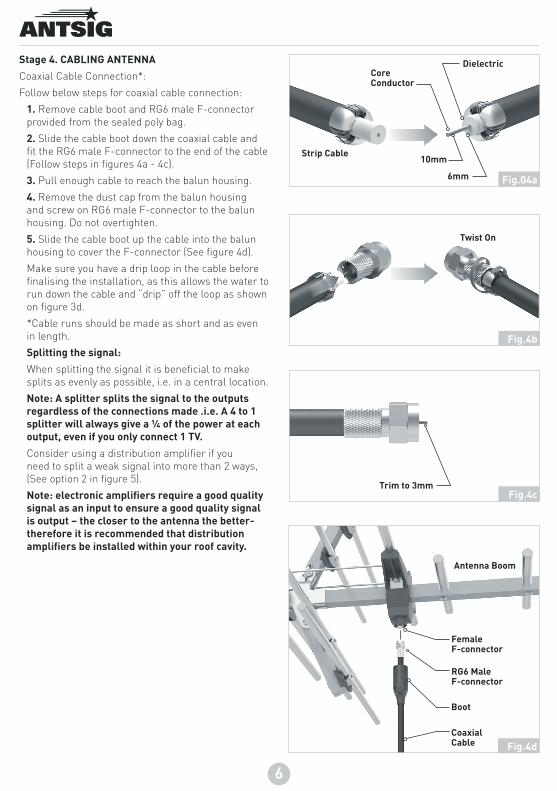
Stage 4. CABLING ANTENNA
Coaxial Cable Connection*:
Follow below steps for coaxial cable connection:
1. Remove cable boot and RG6 male F-connector provided from the sealed poly bag.
2. Slide the cable boot down the coaxial cable and fit the RG6 male F-connector to the end of the cable (Follow steps in figures 4a - 4c).
3. Pull enough cable to reach the balun housing.
4. Remove the dust cap from the balun housing and screw on RG6 male F-connector to the balun housing. Do not overtighten.
5. Slide the cable boot up the cable into the balun housing to cover the F-connector (See figure 4d).
Make sure you have a drip loop in the cable before finalising the installation, as this allows the water to run down the cable and “drip” off the loop as shown on figure 3d.
*Cable runs should be made as short and as even in length.
Splitting the signal:
When splitting the signal it is beneficial to make splits as evenly as possible, i.e. in a central location.
Note: A splitter splits the signal to the outputs regardless of the connections made .i.e. A 4 to 1 splitter will always give a ¼ of the power at each output, even if you only connect 1 TV.
Consider using a distribution amplifier if you need to split a weak signal into more than 2 ways, (See option 2 in figure 5).
Note: electronic amplifiers require a good quality signal as an input to ensure a good quality signal is output – the closer to the antenna the better- therefore it is recommended that distribution amplifiers be installed within your roof cavity.
Antenna Boom
Boot
RG6 Male F-connector
Female F-connector
Fig.4d
Fig.04a
Core Conductor
10mm
6mm
Dielectric
Fig.4b
Trim to 3mmFig.4c
6
Strip Cable
Twist On
Coaxial Cable

TV 1
MASTHEADAMPLIFIER
TV
IN
MASTHEAD AMPLIFIER
VHF/UHF IN UHF IN OUT OUT
POWER PASS
OUTSIDE
INSIDE
SPLITTER
BALUN
ANTENNAMAST
CABLE DRIP LOOP
FLY LEAD
ANTENNA
RG6 QUADCABLE
IN
OU
TO
UT
IN
OU
TO
UT
OUTSIDE
ROOF CAVITY
INSIDE
‘F’ CONNECTORTV OUTLET
‘F’ CONNECTORTV OUTLET
OUTSIDE
INSIDEDISTRIBUTION
AMPLIFIER
TO OTHER TVOUTLETSTV 1
TV 1
3 421UHFVHF/Combo
TO ANTENNA
TO TRANSMITTER
TO ANTENNA
ROOF CAVITY
INSIDE
Stage 5. FINAL INSTALLATION
Final installation of the antenna should be done similar to example below:
Fig.5
OPTION 1.
Masthead Amplifier
Recommended for low signal areas
Mount on antenna mast or near by wall
Requires 240 volt supply
OPTION 2.
Distribution Amplifier
Recommended for multiple TV’s
Requires roof cavity mounting
Requires 240 volt supply
7

WarrantyArlec guarantees this product in accordance with the Australian Consumer Law.
Arlec also warrants to the original first purchaser of this product (“you”) from a retailer that this product will be free of defects in materials and workmanship for a period of 12 months from the date of purchase; provided the product is not used or installed other than for the purpose, or in a manner not within the scope of the recommendations and limitations, specified by Arlec, is new and not damaged at the time of purchase, has been properly installed by a licensed electrician or contractor who is licensed to install electrical products in the place in which the product was installed and in accordance with Arlec’s installation instructions, has been maintained in accordance with the recommendations specified by Arlec, has not been subjected to abuse, misuse, neglect or damage, has not been modified or repaired without the approval of Arlec and has not been used for, or installed in premises which are used for, commercial purposes (“Warranty”).
If you wish to claim on the Warranty, you must, at your own expense, return the product or that part of the product which you believe is defective in materials and workmanship, and provide proof of original purchase, your name, address and telephone number and a certificate of installation or other document required by law for the installation of electrical products in the place in which the product was installed issued by the licensed electrician or contractor who installed the product, to Arlec at the address below within 12 months from the date of purchase. Please note that the Warranty does not cover removal or re-installation of the product or that part of the product which you believe is defective.
Arlec will assess any claim you may make on the Warranty in the above manner and if, in Arlec’s reasonable opinion, the Warranty applies, Arlec will at its own option and expense replace the product (or part of the product) with the same or similar product (or part of the product) or repair the product (or part of the product) and return it to you or refund the price you paid for the product. Arlec will bear its own expenses of doing those things, and you must bear any other expenses of claiming on the Warranty.
The Warranty is in addition to other rights and remedies you may have under a law in relation to the product to which the Warranty relates.
Our goods come with guarantees that cannot be excluded under the Australian Consumer Law. You are entitled to a replacement or refund for a major failure and for compensation for any other reasonably foreseeable loss or damage. You are also entitled to have the goods repaired or replaced if the goods fail to be of acceptable quality and the failure does not amount to a major failure.
Arlec Australia Pty. Ltd. ACN 009 322 105 (“Arlec”) gives the Warranty. Arlec’s telephone number, address and email address are:Customer Service: (03) 9982 5111
Building 3, 31 – 41 Joseph Street, Blackburn North, Victoria, 3130Blackburn North LPO, P.O. Box 1065, Blackburn North, 3130Email: [email protected]
CPIN002654/2
TROUBLESHOOTING & PIXELATION INFORMATION
Digital TV sets now require the received signal level to be within its operating boundaries. A signal level between 45dBμV and 80dBμV is most ideal and will present a perfect picture. If the signal is outside of these levels, pixilation will occur whether it is too much or too little.
The most likely causes of pixilation will be poor signal collection. Though in some cases, having too large an antenna for your distribution network, or an amplifier that is not required, can cause too much signal for your TV. This can be reduced easily with the introduction of a splitter.
To fix/prevent pixilation you can try the following:
• Check antenna direction;
• Check for sources of interference and noise- power cables, exhaust fans, air conditioners, etc. try to avoid running coax cable within close proximity to these;
• Check all connections in the system for wear, corrosion and proper termination;
• Start behind the TV, then the coaxial cable connection to the antenna’s boom, before continuing through the distribution network;
• Try re-terminating connection points- this should eliminate any poor terminations – the most common cause in new installations. Again start at the rear of the TV, the antenna coaxial cable connection, then through the distribution network.
DIGITAL HD TV ANTENNA INSTALLATION GUIDE
ANTSIG is proudly produced by Arlec Australia