digital gas detector/controller - opera...
TRANSCRIPT

Inc.5000 Series Digital Gas Detector/Controller
Operation Manual
5000 Series Digital Gas Detector/Controller
TABLE OF CONTENTSGeneral Description Applications FeaturesModel Selection GuideCharacteristicsInstallation Installation GuideOperation Screen Display Settings Display Settings Changing Settings Settings General SettingsNetwork Configuration Using Central Controller Using No Central Controller Defaults Addresses Creating Zones or Groups Output RelaysMaintenance Guide Quick Test Caution Calibration Procedure
1.0 1.1 1.22.03.04.0 4.15.0 5.1 5.2 5.3 5.4 5.5 5.66.0 6.1 6.2 6.3 6.4 6.5 6.67.0 7.1 7.2
Inc.
5000 Series Digital Gas Detector/Controller
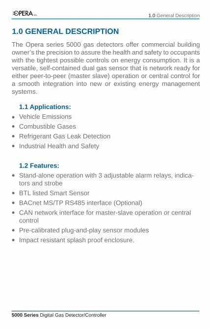
The Opera series 5000 gas detectors offer commercial building owner’s the precision to assure the health and safety to occupants with the tightest possible controls on energy consumption. It is a versatile, self-contained dual gas sensor that is network ready for either peer-to-peer (master slave) operation or central control for a smooth integration into new or existing energy management systems.
1.0 GENERAL DESCRIPTION
1.1 Applications:Vehicle EmissionsCombustible GasesRefrigerant Gas Leak DetectionIndustrial Health and Safety
1.2 Features:Stand-alone operation with 3 adjustable alarm relays, indica-tors and strobeBTL listed Smart SensorBACnet MS/TP RS485 interface (Optional)CAN network interface for master-slave operation or central controlPre-calibrated plug-and-play sensor modulesImpact resistant splash proof enclosure.
1.0 General DescriptionInc.
5000 Series Digital Gas Detector/Controller
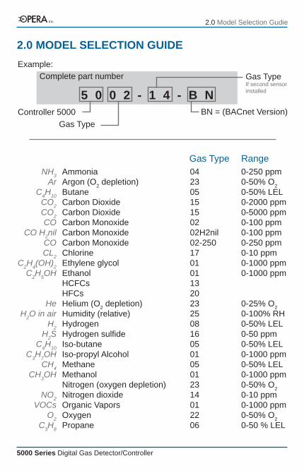
2.0 MODEL SELECTION GUIDE
AmmoniaArgon (O2 depletion)ButaneCarbon DioxideCarbon DioxideCarbon MonoxideCarbon MonoxideCarbon MonoxideChlorineEthylene glycolEthanolHCFCsHFCsHelium (O2 depletion)Humidity (relative)HydrogenHydrogen sulfideIso-butaneIso-propyl AlcoholMethaneMethanolNitrogen (oxygen depletion)Nitrogen dioxideOrganic VaporsOxygenPropane
NH3Ar
C4H10CO2CO2CO
CO H2nilCOCL2
C2H4(OH)2C2H5OH
HeH2O in air
H2H2S
C4H10C3H7OH
CH4CH3OH
NO2VOCs
O2C3H8
04230515150202H2nil02-250170101132023250816050105012314012206
0-250 ppm0-50% O20-50% LEL0-2000 ppm0-5000 ppm0-100 ppm0-100 ppm0-250 ppm0-10 ppm0-1000 ppm0-1000 ppm
0-25% O20-100% RH0-50% LEL0-50 ppm0-50% LEL0-1000 ppm0-50% LEL0-1000 ppm0-50% O20-10 ppm0-1000 ppm0-50% O20-50 % LEL
Gas Type Range
Controller 5000
Example:
5 0 0 2 - 1 4 - B NBN = (BACnet Version)
Gas Type
Complete part number Gas TypeIf second sensor installed
2.0 Model Selection GudieInc.

5000 Series Digital Gas Detector/Controller
3.0 SPECIFICATIONSOutputs:Digital networks CAN network for central control or peer-to-peer BACnet MS/TP RS485 (BTL listed) (Optional)Relays SPDT, 5 amp @ 125 vac, non-inductive On delay; 0-999 seconds (16 minutes) Off delay; 0-999 seconds (16 minutes)
User Interface:LCD display shows gas concentration, user settings, calibra-tion controlsAudible alarm, 80 db on level 3 at 1 meter4 pushbutton user keypadPassword control for settings
3.0 SpecificationsInc.
5000 Series Digital Gas Detector/Controller
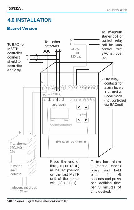
1 2 3 24 v - A B - +
www.detecteursdegaz.com
Alarm
Opéra 5000
Options
1615141312111098
FDL 2000 191817
7654321
+ -N
first 50xx-BN detector
NL
+-
To BACnet MS/TP controllerconnect sheild to controller end only
Transformer 120/240 to 24v
5 va for each detector
N L
Conc.
24 vacor
120 vac
Independant circuit 120 vac
To magnetic starter coil or control relay coil for local control with BACnet over ride
Dry relay contacts for alarm levels 1, 2, and 3 Local mode (not controled via BACnet)
Place the end of line jumper (FDL) in the left position on the last MSTP unit of the series wiring (the ends)
To test local alarm 1 (manual mode) press and hold button for >5 seconds and press one addition time per 5 minutes of time desired.
To other detectors
4.0 INSTALLATION
4.0 Installation
Bacnet Version
Inc.

5000 Series Digital Gas Detector/Controller
1 2 3 24 v - A B - +
www.detecteursdegaz.com
Options
16151413121110987654321
N
first 50xx detector
NL
Transformer 120/24v
5 va for each unit
N L
Alarm
Opéra 5000
Conc.
24 vacor
120 vac
Independant circuit 120 vac
To magnetic starter coil or control relay coil
Dry relay contacts for alarm levels 1, 2, and 3
Place the end of line jumper (EOL) in the upper position on the first and last units of the series wiring (the ends)
To test local alarm 1 (manual mode) press and hold button for >5 seconds and press one addition time per 5 minutes of time desired.
To other detectors
4.0 INSTALLATION (Continued)
4.0 Installation
Output 4-20 ma or 2-10v
Up for 4-20 ma output down 2-10v output
++-
BA
Com
Inc.
5000 Series Digital Gas Detector/Controller
1.2.
3.
4.
5.
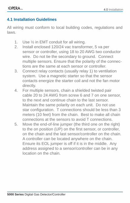
Use ½ in EMT conduit for all wiring.Install enclosed 120/24 vac transformer, 5 va per sensor or controller, using 18 to 20 AWG two conductor wire. Do not tie the secondary to ground. Connect multiple sensors. Ensure that the polarity of the connec-tions are the same at each sensor or controller.Connect relay contacts (usually relay 1) to ventilation system. Use a magnetic starter so that the sensor contacts energize the starter coil and not the fan motor directly.For multiple sensors, chain a shielded twisted pair cable 20 to 24 AWG from screw 6 and 7 on one sensor, to the next and continue chain to the last sensor. Maintain the same polarity on each unit. Do not use star configuration. T connections should be less than 3 meters (10 feet) from the chain. Best to make all chain connections at the sensors to avoid T connections.Move the end-of-line jumper (the third one on the right) to the on position (UP) on the first sensor, or controller, on the chain and the last sensor/controller on the chain. A controller can be located anywhere on the chain. Ensure its EOL jumper is off if it is in the middle. Any address assigned to a sensor/controller can be in any location on the chain.
4.0 Installation
4.1 Installation Guidelines
All wiring must conform to local building codes, regulations and laws.
Inc.

5000 Series Digital Gas Detector/Controller
4.2 Installation Guidelines (Continued)
6.
7.
Power on the units. They will display the gas type and reading. To verify if the sensors are communicating correctly, change setting no. 56 from 0 to 1 to turn on the network display. Press ↑ and ← simultaneously to save then press and hold ← for a few seconds. The unit will display each sensor connected. If the unit does not display the other sensors scrolling by, check the follow-ing;
To test communication, press and hold the up button on sensor for 5 seconds to start manual mode (5 minutes). This will close the relay 1 on that unit and all of the other units on the network.
each unit has a unique address, setting 39, with no duplicatesend-of-line jumpers are set on units at ends of cable onlypolarity of the communication cable and the 24 vacwire connections for shorts, etc.
4.0 InstallationInc.
5000 Series Digital Gas Detector/Controller
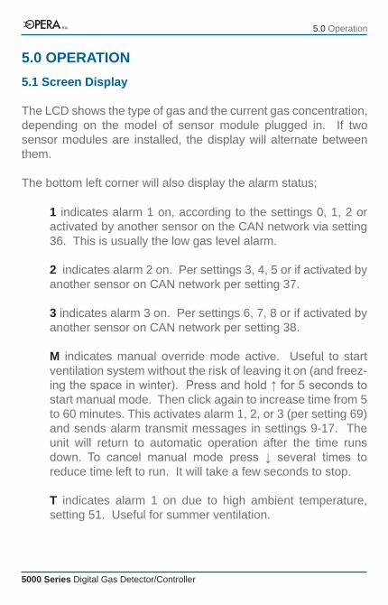
5.0 OPERATION5.1 Screen Display
The LCD shows the type of gas and the current gas concentration, depending on the model of sensor module plugged in. If two sensor modules are installed, the display will alternate between them.
The bottom left corner will also display the alarm status;
1 indicates alarm 1 on, according to the settings 0, 1, 2 or activated by another sensor on the CAN network via setting 36. This is usually the low gas level alarm.
2 indicates alarm 2 on. Per settings 3, 4, 5 or if activated by another sensor on CAN network per setting 37.
3 indicates alarm 3 on. Per settings 6, 7, 8 or if activated by another sensor on CAN network per setting 38.
M indicates manual override mode active. Useful to start ventilation system without the risk of leaving it on (and freez-ing the space in winter). Press and hold ↑ for 5 seconds to start manual mode. Then click again to increase time from 5 to 60 minutes. This activates alarm 1, 2, or 3 (per setting 69) and sends alarm transmit messages in settings 9-17. The unit will return to automatic operation after the time runs down. To cancel manual mode press ↓ several times to reduce time left to run. It will take a few seconds to stop.
T indicates alarm 1 on due to high ambient temperature, setting 51. Useful for summer ventilation.
5.0 OperationInc.

5000 Series Digital Gas Detector/Controller
5.2 Settings
User settings are factory pre-loaded with default values to facili-tate set up and can be changed at any time. Upgrading firmware will not affect user settings.
Alarm thresholds should be set to suit local regulations. Default values for these are general guidelines only.
5.3 Displaying Settings
Press → and ← to move through the settings. If the keypad lock is on then enter the password first. The screen will display the setting number 0, 1, 2, etc plus the short description (eg; AL1) and the current setting value.
5.4 Changing Settings
Press the ↑ or ↓ buttons to increase or decrease the setting.To save, press ↑ and ← buttons at the same time. The word “OK” will appear. If you do not see “OK” and the new value it is because the buttons were not pressed simultaneously. Try again.
5.0 OperationInc.
5000 Series Digital Gas Detector/Controller
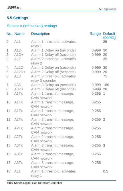
Sensor A (left socket) settings
No. Name Range
0
123
456
789
10
11
12
13
14
15
16
17
18
AL1
A1D-A1D+AL2
AL2D-AL2D+AL3
A3D-A3D+A1Tx
A1Tx
A1Tx
A2Tx
A2Tx
A2Tx
A3Tx
A3Tx
A3Tx
AL1
Alarm 1 threshold, activates relay 1Alarm 1 Delay on (seconds)Alarm 1 Delay off (seconds)Alarm 2 threshold, activates relay 2Alarm 2 Delay on (seconds)Alarm 2 Delay off (seconds)Alarm 3 threshold, activates relay 3 sounder Alarm 3 Delay on (seconds)Alarm 3 Delay off (seconds)Alarm 1 transmit message, CAN networkAlarm 1 transmit message, CAN networkAlarm 1 transmit message, CAN networkAlarm 2 transmit message, CAN networkAlarm 2 transmit message, CAN networkAlarm 2 transmit message, CAN networkAlarm 3 transmit message, CAN networkAlarm 3 transmit message, CAN networkAlarm 3 transmit message, CAN networkAlarm 1 threshold, activates relay 1
0-9990-999
0-9990-999
0-9990-9990-255
0-255
0-255
0-255
0-255
0-255
0-255
0-255
0-255
25
302035
302075
180201
2
3
0.5
Default(CO/NO2)
Description
5.5 Settings
5.0 OperationInc.

5000 Series Digital Gas Detector/Controller
No. Name RangeDescription
192021
222324
252627
28
29
30
31
32
33
34
35
36
37
A1D-A1D+AL2
A2D-A2D+AL3
A3D-A3D+A1x
AL1Tx
A1Tx
A2Tx
A2Tx
A2Tx
A3Tx
A3Tx
A3Tx
X>R1
XR2
Alarm 1 Delay on (seconds)Alarm 1 Delay off (seconds)Alarm 2 threshold, activates relay 2Alarm 2 Delay on (seconds)Alarm 2 Delay off (seconds)Alarm 3 threshold, activates relay 3 sounderAlarm 3 Delay on (seconds)Alarm 3 Delay off (seconds)Alarm 1 transmit message, CAN networkAlarm 1 transmit message, CAN networkAlarm 1 transmit message, CAN networkAlarm 2 transmit message, CAN networkAlarm 2 transmit message, CAN networkAlarm 2 transmit message, CAN networkAlarm 3 transmit message, CAN networkAlarm 3 transmit message, CAN networkAlarm 3 transmit message, CAN networkReceive message to activate reelay 1, CAN networkReceive message to activate reelay 2, CAN network
0-9990-999
0-9990-999
0-9990-9990-255
0-255
0-255
0-255
0-255
0-255
0-255
0-255
0-255
0-255
0-255
30201.0
30202
180201
2
3
1
2
Default(CO/NO2)
5.5 Settings (Continued)
5.0 Operation
Sensor B (right socket) settings
Inc.
5000 Series Digital Gas Detector/Controller
No. Name RangeDescription
38
3940
41
42
43
4445
46
464748
49
XR3
AdrAnZA
AnSA
AnZB
AnSB
TempAud
BAC
NetBMABBR
PASS
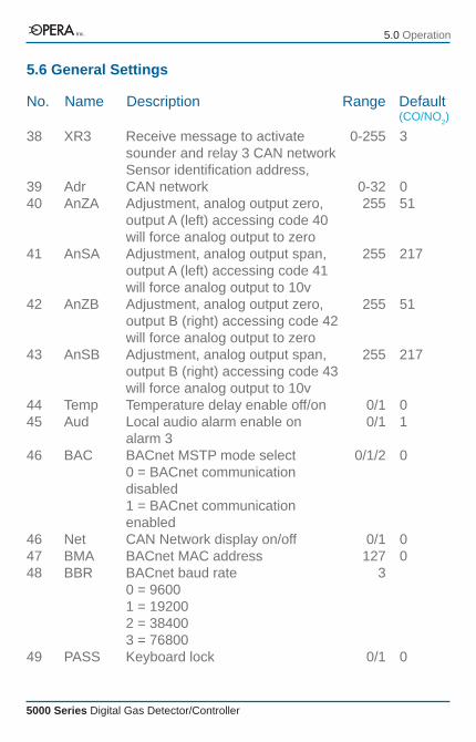
Receive message to activate sounder and relay 3 CAN networkSensor identification address, CAN networkAdjustment, analog output zero, output A (left) accessing code 40 will force analog output to zeroAdjustment, analog output span, output A (left) accessing code 41 will force analog output to 10vAdjustment, analog output zero, output B (right) accessing code 42 will force analog output to zeroAdjustment, analog output span, output B (right) accessing code 43 will force analog output to 10vTemperature delay enable off/onLocal audio alarm enable on alarm 3BACnet MSTP mode select0 = BACnet communication disabled1 = BACnet communication enabledCAN Network display on/offBACnet MAC addressBACnet baud rate0 = 96001 = 192002 = 384003 = 76800Keyboard lock
0-255
0-32255
255
255
255
0/10/1
0/1/2
0/1127
3
0/1
3
051
217
51
217
01
0
00
0
Default(CO/NO2)
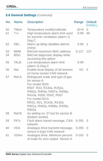
5.6 General Settings
5.0 OperationInc.
5000 Series Digital Gas Detector/Controller
No. Name RangeDescription
5051
52
5354
55
56
57
58
59
60
61
TModT+/-
DEL
BMMBDG
TALB
Net
Ref-A
Ref-B
FltTx
VDA
VDAm
Tempurature modify/calibrateHigh tempurature alarm limit used for summer ventilation (alarm 1) Deg CWarm up delay disables alarms (mins)BACnet maximum MAC addressBACnet diagnostic display while accessing this optionLow tempurature alarm limit (alarm 3) Deg CEnable local display of all sensors on home screen CAN networkRefrigerant scale and type of gas for sensor AFor model 5520:R507, R23, R134a, R152a, R492a, R404a, R407a, R408a, R410a, R500, R502, R507For model 5513:RR22, R21, R141b, R142b, R401a, R402a, R408a, R409a, R502aAs setting no. 57 but for sensor B (bottom socket)Fault alarm transit message, CAN networkAnalogue drive transmit message, sensor A (top) CAN networkAnalogue drive. Minimum percent of scale for zero output. Sensor A
-9/+90-99
0-99
0-127
0-99
0/1
0-255
0-255
0-100
060
1
127
0
0
0
0
Default(CO/NO2)
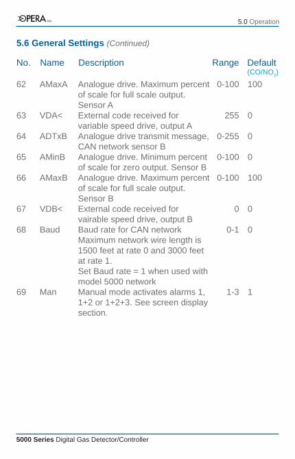
5.6 General Settings (Continued)
5.0 OperationInc.
5000 Series Digital Gas Detector/Controller
No. Name RangeDescription
62
63
64
65
66
67
68
69
AMaxA
VDA<
ADTxB
AMinB
AMaxB
VDB<
Baud
Man
Analogue drive. Maximum percent of scale for full scale output. Sensor AExternal code received for variable speed drive, output A Analogue drive transmit message, CAN network sensor BAnalogue drive. Minimum percent of scale for zero output. Sensor BAnalogue drive. Maximum percent of scale for full scale output. Sensor BExternal code received for vairable speed drive, output BBaud rate for CAN networkMaximum network wire length is 1500 feet at rate 0 and 3000 feet at rate 1.Set Baud rate = 1 when used with model 5000 networkManual mode activates alarms 1, 1+2 or 1+2+3. See screen display section.
0-100
255
0-255
0-100
0-100
0
0-1
1-3
100
0
0
0
100
0
0
1
Default(CO/NO2)
5.6 General Settings (Continued)
5.0 OperationInc.
5000 Series Digital Gas Detector/Controller
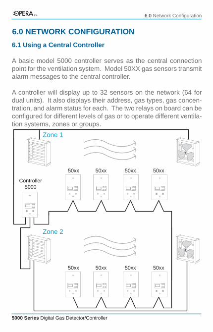
6.1 Using a Central Controller
A basic model 5000 controller serves as the central connection point for the ventilation system. Model 50XX gas sensors transmit alarm messages to the central controller.
A controller will display up to 32 sensors on the network (64 for dual units). It also displays their address, gas types, gas concen-tration, and alarm status for each. The two relays on board can be configured for different levels of gas or to operate different ventila-tion systems, zones or groups.
6.0 NETWORK CONFIGURATION
6.0 Network Configuration
Controller5000
Zone 1
Zone 2
50xx 50xx 50xx 50xx
50xx 50xx 50xx 50xx
Inc.

5000 Series Digital Gas Detector/Controller
50xx 50xx 50xx 50xx
Zone 1
Zone 2
6.0 Network Configuration
6.2 Using No central controller (master/slave operation)
One of the 50XX series gas sensors can perform the same func-tion as the controller. It can activate the ventilation for all the sensors, or a group. The use of a dedicated controller is optional, - to add a display in some specific location, such as before enter-ing a mechanical room or interface with several fan starters which are located in one place. The low cost of a basic controller makes it easy to use them to reduce costly field wiring where needed.
50xx 50xx 50xx 50xx
Inc.
5000 Series Digital Gas Detector/Controller
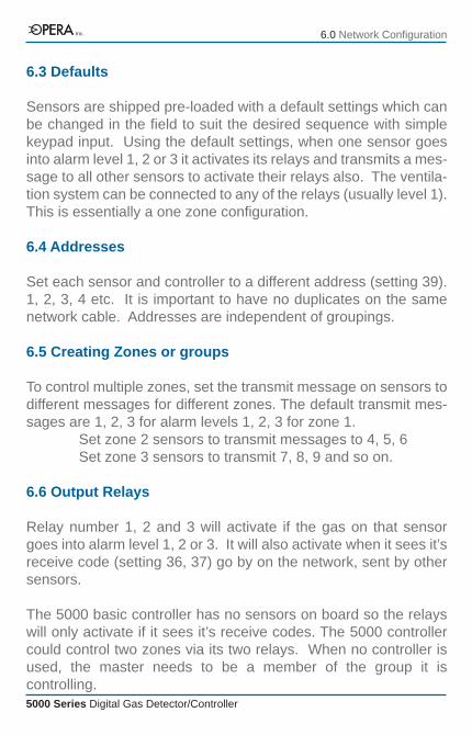
6.3 Defaults
Sensors are shipped pre-loaded with a default settings which can be changed in the field to suit the desired sequence with simple keypad input. Using the default settings, when one sensor goes into alarm level 1, 2 or 3 it activates its relays and transmits a mes-sage to all other sensors to activate their relays also. The ventila-tion system can be connected to any of the relays (usually level 1). This is essentially a one zone configuration.
6.4 Addresses
Set each sensor and controller to a different address (setting 39). 1, 2, 3, 4 etc. It is important to have no duplicates on the same network cable. Addresses are independent of groupings.
6.5 Creating Zones or groups
To control multiple zones, set the transmit message on sensors to different messages for different zones. The default transmit mes-sages are 1, 2, 3 for alarm levels 1, 2, 3 for zone 1. Set zone 2 sensors to transmit messages to 4, 5, 6 Set zone 3 sensors to transmit 7, 8, 9 and so on.
6.6 Output Relays
Relay number 1, 2 and 3 will activate if the gas on that sensor goes into alarm level 1, 2 or 3. It will also activate when it sees it’s receive code (setting 36, 37) go by on the network, sent by other sensors.
The 5000 basic controller has no sensors on board so the relays will only activate if it sees it’s receive codes. The 5000 controller could control two zones via its two relays. When no controller is used, the master needs to be a member of the group it is controlling.
6.0 Network ConfigurationInc.

5000 Series Digital Gas Detector/Controller
All sensors are shipped from the factory pre-calibrated. To main-tain accuracy and conformity with standards it is essential that they be calibrated by a qualified technician at least once per year using certified bottled gas mixtures.
7.1 Quick Test CautionOpera does not approve the use of the so called “bump test”. Here, a gas of a higher concentration than the alarm level is simply injected into the sensor to cause the alarm to trigger. The gas in these bottles is a higher concentration than what is used for proper calibration. This only test the operation of the alarm with no regard for the intended alarm settings, similar to simply press-ing a test button.
Use certified precision mixtures to adjust the sensitivity of the sensor due to normal wear and aging and guarantee that the designed alarm set points are respected. It will also indicate the general condition of a sensor that is due for replacement. So called “automatic calibration” or “self-test” will not provide this level of security.
7.0 MAINTENANCE GUIDE
7.0 Maintenance GuideInc.
5000 Series Digital Gas Detector/Controller
1.
2.3.
4.
5.6.7.
8.
9.
10.11.
12.
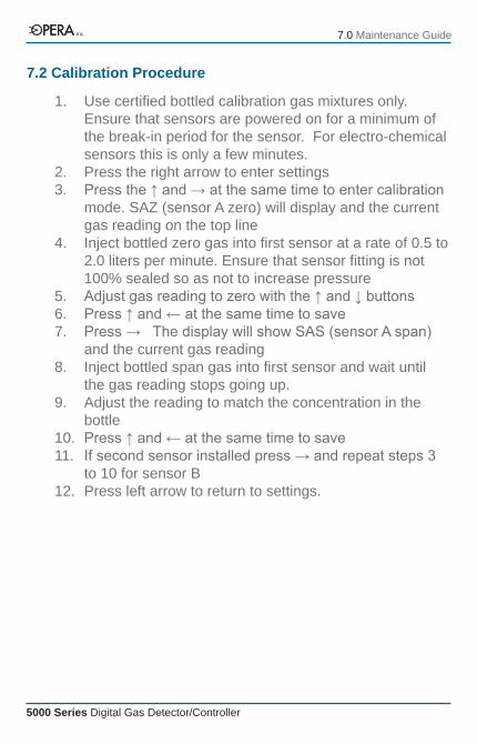
Use certified bottled calibration gas mixtures only. Ensure that sensors are powered on for a minimum of the break-in period for the sensor. For electro-chemical sensors this is only a few minutes.Press the right arrow to enter settingsPress the ↑ and → at the same time to enter calibration mode. SAZ (sensor A zero) will display and the current gas reading on the top lineInject bottled zero gas into first sensor at a rate of 0.5 to 2.0 liters per minute. Ensure that sensor fitting is not 100% sealed so as not to increase pressureAdjust gas reading to zero with the ↑ and ↓ buttonsPress ↑ and ← at the same time to savePress → The display will show SAS (sensor A span) and the current gas readingInject bottled span gas into first sensor and wait until the gas reading stops going up.Adjust the reading to match the concentration in the bottlePress ↑ and ← at the same time to saveIf second sensor installed press → and repeat steps 3 to 10 for sensor BPress left arrow to return to settings.
7.2 Calibration Procedure
7.0 Maintenance GuideInc.