digital-flotm boiler water/water plate & frame heat · pdf fileheat exchanger for future...
TRANSCRIPT
Armstrong International221 Armstrong Blvd., Three Rivers, Michigan, 49093 - USAPh. (269) 279-3602 Toll Free (888) HOT-HOSE (468-4673) Fax (269) 279-3130
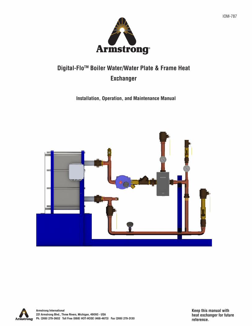
Keep this manual with heat exchanger for future reference.
Digital-FloTM Boiler Water/Water Plate & Frame Heat
Exchanger
Installation, Operation, and Maintenance Manual
IOM-787
Armstrong International221 Armstrong Blvd., Three Rivers, Michigan, 49093 - USAPh. (269) 279-3602 Toll Free (888) HOT-HOSE (468-4673) Fax (269) 279-3130
Armstrong
ContentsSafety .................................................1
General Description ................................2
Specifications .......................................4
Operational Specifications . . . . . . . . . . . . . . . . . . . . . . . . . . . . . 4
Technical Specifications . . . . . . . . . . . . . . . . . . . . . . . . . . . . . . . . . 4
Materials of Construction . . . . . . . . . . . . . . . . . . . . . . . . . . . . . . . 5
Dimensions . . . . . . . . . . . . . . . . . . . . . . . . . . . . . . . . . . . . . . . . . . . . . . . . . . . 6
Installation ...........................................7
General Information . . . . . . . . . . . . . . . . . . . . . . . . . . . . . . . . . . . . . . . 7
Typical Installation . . . . . . . . . . . . . . . . . . . . . . . . . . . . . . . . . . . . . . . . 8
Commissioning . . . . . . . . . . . . . . . . . . . . . . . . . . . . . . . . . . . . . . . . . . . . . 9
Periodic Maintenance ............................ 10
Troubleshooting ................................... 11
Parts Lists .......................................... 14
Limited Warranty and Remedy ................. 16
Notes................................................ 17
Armstrong InternationalIOM-787Digital-Flo Plate & Frame Heat ExchangerWater/Water
Page 1 of 18
Safety
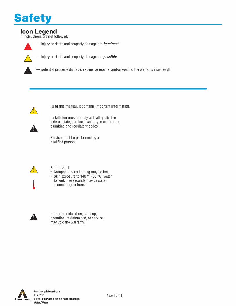
— injury or death and property damage are imminent
— injury or death and property damage are possible
— potential property damage, expensive repairs, and/or voiding the warranty may result
Icon LegendIf instructions are not followed:
Installation must comply with all applicable federal, state, and local sanitary, construction, plumbing and regulatory codes.
Burn hazard• Components and piping may be hot.• Skin exposure to 140 °F (60 °C) water
for only five seconds may cause a second degree burn.
Read this manual. It contains important information.
Service must be performed by a qualified person.
Improper installation, start-up, operation, maintenance, or service may void the warranty.
Armstrong InternationalIOM-787Digital-Flo Plate & Frame Heat ExchangerWater/Water
Page 2 of 18
Armstrong reserves the right to make design or specification changes without notification.
DRV40, DRV50, or DRV80 digital recirculating valveHeat exchanger module (ASME stamped)ThermometersCheck valvesInlet strainer(s)Isolation valvesSafety shut-off valves
Note: Because the Digital-Flo is customizable, there may be components that are not addressed in this IOM.
Standard Components:
The Digital-Flo Boiler Water/Water Plate and Frame Heat Exchanger uses digital technology to monitor water temperature (inlet hot and inlet cold/system return), eliminating the need for the following components:• Boiler Water Control Valve• PID Controller• High Temperature Limit Thermostat• High Temperature Limit Controller• Cold Water Injection Valve• Internal Circulating Pump• Compressed Air RequirementThe secondary (sometimes called domestic) side of all units is equipped with a safety shut-off valve.Units are shipped pre-piped and pressure tested.All Digital-Flo units may be integrated into Building Automation Systems or LANs.
Among the available options:Boiler water greater than 160 °F units—optimized for 180 °F (82.2 °C) in and 150 °F (65.6 °C) out.Boiler water less than 160 °F units—optimized for 150 °F (65.6 °C) in and 115 °F (46.1 °C) out.
Note: In this manual "DF" stands for "Digital Flo" and is the brand designation. "PHE" stands for "Plate Heat Exchanger" as distinct from a tube and shell type.
General Description
SHEET 1 OF 1
CONCEPT HW PLATE FRAME ASSY
REV DWG.
NAME DATE
DRAWN MATERIAL
TOLERANCES UNLESSOTHERWISE SPECIFIED
ARMSTRONG INTERNATIONAL
FRACTIONAL 1/64ANGULAR: 2 IN. MMDECIMAL .XXXX .0005 ----- .XXX .005 .010 .XX .015 .10 .X ---------- .3
Copyright C 2010 ARMSTRONG INTERNATIONAL, INC.
RELEASED
DO NOT SCALE DRAWING
DIMENSIONINGENGLISH [mm]
Armstrong InternationalIOM-787Digital-Flo Plate & Frame Heat ExchangerWater/Water
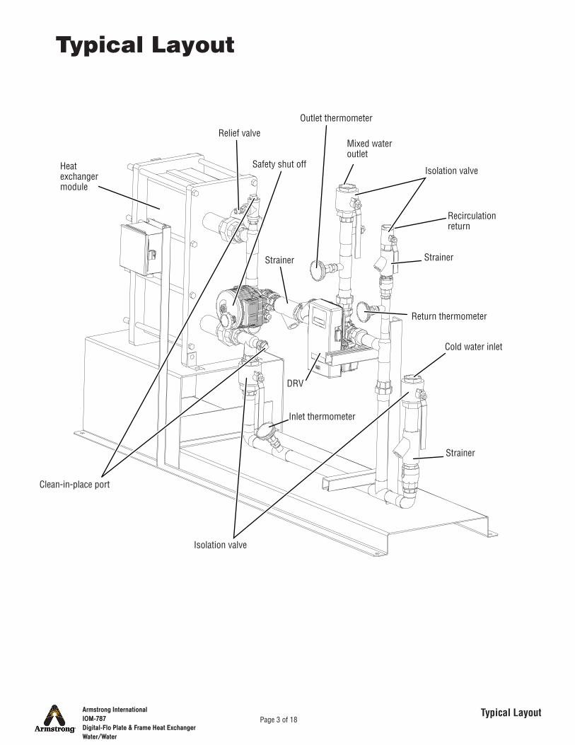
Page 3 of 18Typical Layout
Relief valve
Safety shut off
Outlet thermometer
Isolation valve
Return thermometer
Strainer
Inlet thermometer
Isolation valve
Clean-in-place port
Heat exchanger module
DRV
Cold water inlet
Recirculation return
Mixed water outlet
Typical Layout
StrainerStrainer
Armstrong InternationalIOM-787Digital-Flo Plate & Frame Heat ExchangerWater/Water
Page 4 of 18Technical Specifications
Operational Specifications
Technical Specifications
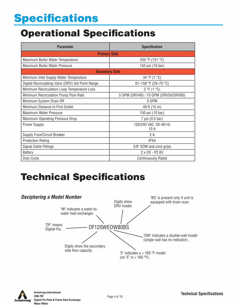
Specifications
Parameter Specification
Primary SideMaximum Boiler Water Temperature 250 °F (121 °C)Maximum Boiler Water Pressure 150 psi (10 bar)
Secondary SideMinimum Inlet Supply Water Temperature 34 °F (1 °C)Digital Recirculating Valve (DRV) Set Point Range 81–158 °F (29–70 °C)Minimum Recirculation Loop Temperature Loss 2 °F (1 °C)Minimum Recirculation Pump Flow Rate 5 GPM (DRV40) / 10 GPM (DRV50/DRV80)Minimum System Draw Off 0 GPMMinimum Distance to First Outlet 49 ft (15 m)Maximum Water Pressure 150 psi (10 bar)Maximum Operating Pressure Drop 7 psi (0.5 bar)Power Supply 120/240 VAC 50–60 Hz
10 ASupply Fuse/Circuit Breaker 3 AProtection Rating IPX4Signal Cable Fittings 3/8" SOW and cord gripsBattery 2 x CR - P2 6VDuty Cycle Continuously Rated
DF120WEDW80BS
Deciphering a Model Number
"DF" means Digital-Flo.
Digits show the secondary side flow capacity.
"W" indicates a water-to-water heat exchanger.
"E" indicates a < 160 °F model (no "E" is > 160 °F).
"DW" indicates a double-wall model (single wall has no indicator).
Digits show DRV model.
"BS" is present only if unit is equipped with brain scan.
Armstrong InternationalIOM-787Digital-Flo Plate & Frame Heat ExchangerWater/Water
Page 5 of 18Materials of Construction
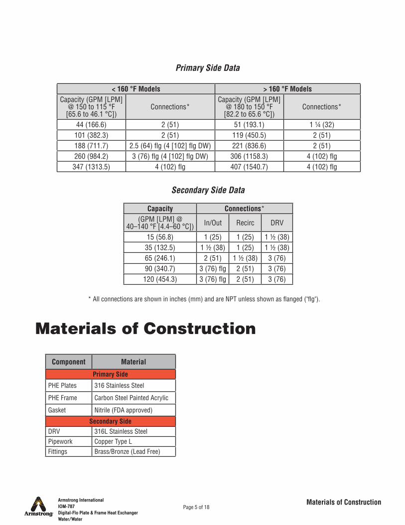
Capacity Connections*(GPM [LPM] @
40–140 °F [4.4–60 °C]) In/Out Recirc DRV
15 (56.8) 1 (25) 1 (25) 1 ½ (38)35 (132.5) 1 ½ (38) 1 (25) 1 ½ (38)65 (246.1) 2 (51) 1 ½ (38) 3 (76)90 (340.7) 3 (76) flg 2 (51) 3 (76)120 (454.3) 3 (76) flg 2 (51) 3 (76)
Secondary Side Data
< 160 °F Models > 160 °F ModelsCapacity (GPM [LPM]
@ 150 to 115 °F [65.6 to 46.1 °C])
Connections*Capacity (GPM [LPM]
@ 180 to 150 °F [82.2 to 65.6 °C])
Connections*
44 (166.6) 2 (51) 51 (193.1) 1 ¼ (32)101 (382.3) 2 (51) 119 (450.5) 2 (51)188 (711.7) 2.5 (64) flg (4 [102] flg DW) 221 (836.6) 2 (51)260 (984.2) 3 (76) flg (4 [102] flg DW) 306 (1158.3) 4 (102) flg347 (1313.5) 4 (102) flg 407 (1540.7) 4 (102) flg
Primary Side Data
* All connections are shown in inches (mm) and are NPT unless shown as flanged ("flg").
Materials of Construction
Component Material
Primary Side
PHE Plates 316 Stainless Steel
PHE Frame Carbon Steel Painted Acrylic
Gasket Nitrile (FDA approved)
Secondary SideDRV 316L Stainless SteelPipework Copper Type LFittings Brass/Bronze (Lead Free)
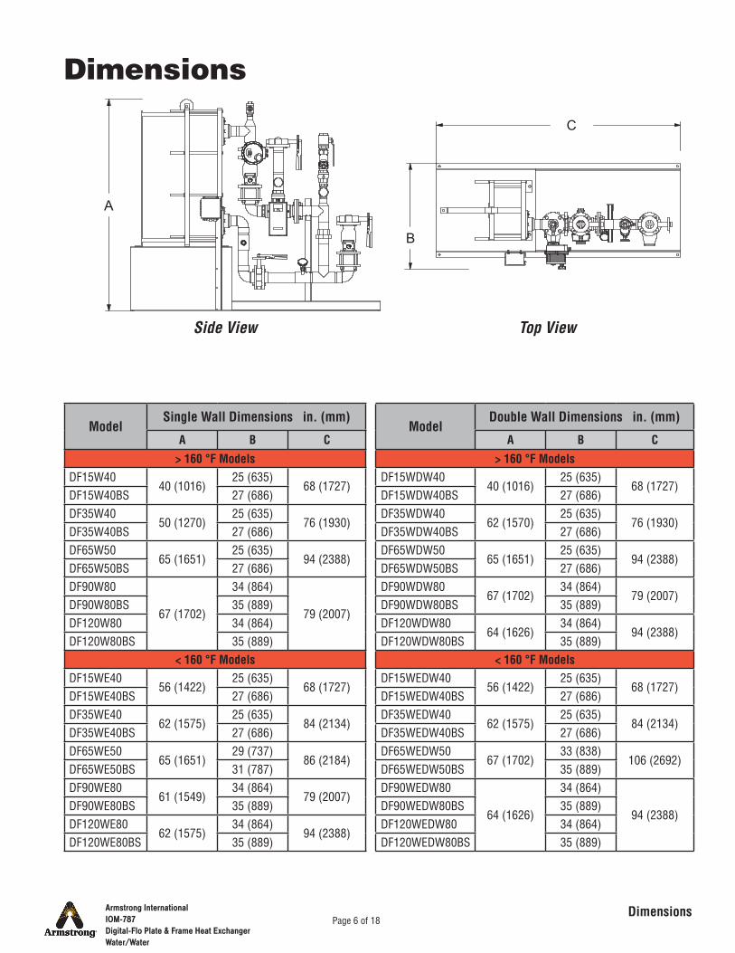
B
C
A
Armstrong InternationalIOM-787Digital-Flo Plate & Frame Heat ExchangerWater/Water
Page 6 of 18Dimensions
Dimensions
ModelSingle Wall Dimensions in. (mm)
A B C
> 160 °F ModelsDF15W40
40 (1016)25 (635)
68 (1727)DF15W40BS 27 (686)DF35W40
50 (1270)25 (635)
76 (1930)DF35W40BS 27 (686)DF65W50
65 (1651)25 (635)
94 (2388)DF65W50BS 27 (686)DF90W80
67 (1702)
34 (864)
79 (2007)DF90W80BS 35 (889)DF120W80 34 (864)DF120W80BS 35 (889)
< 160 °F ModelsDF15WE40
56 (1422)25 (635)
68 (1727)DF15WE40BS 27 (686)DF35WE40
62 (1575)25 (635)
84 (2134)DF35WE40BS 27 (686)DF65WE50
65 (1651)29 (737)
86 (2184)DF65WE50BS 31 (787)DF90WE80
61 (1549)34 (864)
79 (2007)DF90WE80BS 35 (889)DF120WE80
62 (1575)34 (864)
94 (2388)DF120WE80BS 35 (889)
Side View Top View
ModelDouble Wall Dimensions in. (mm)
A B C
> 160 °F ModelsDF15WDW40
40 (1016)25 (635)
68 (1727)DF15WDW40BS 27 (686)DF35WDW40
62 (1570)25 (635)
76 (1930)DF35WDW40BS 27 (686)DF65WDW50
65 (1651)25 (635)
94 (2388)DF65WDW50BS 27 (686)DF90WDW80
67 (1702)34 (864)
79 (2007)DF90WDW80BS 35 (889)DF120WDW80
64 (1626)34 (864)
94 (2388)DF120WDW80BS 35 (889)
< 160 °F ModelsDF15WEDW40
56 (1422)25 (635)
68 (1727)DF15WEDW40BS 27 (686)DF35WEDW40
62 (1575)25 (635)
84 (2134)DF35WEDW40BS 27 (686)DF65WEDW50
67 (1702)33 (838)
106 (2692)DF65WEDW50BS 35 (889)DF90WEDW80
64 (1626)
34 (864)
94 (2388)DF90WEDW80BS 35 (889)DF120WEDW80 34 (864)DF120WEDW80BS 35 (889)
Armstrong InternationalIOM-787Digital-Flo Plate & Frame Heat ExchangerWater/Water
Page 7 of 18General Information
Installation General Information
Locate adjacent to appropriate electrical service.
Always wear appropriate safety clothing and equipment.Isolate all water and condensate lines.Relieve residual pressure in system or connecting piping.Allow hot parts to cool before beginning work.
Notes:• Secondary loop is supplied with enable/disable temperature limit protection.• A secondary system recirculation pump must be installed and be operational
at all times on the inlet to the unit.• Isolating valves should be fitted to primary side connections (not supplied).
Requires primary and secondary side circulating pumps (not supplied).
Follow all applicable codes.
Installation must be performed by designated, qualified, and competent personnel, including a licensed electrician and plumber or pipe fitter.
Position with adequate space for service and maintenance.
SHEET 1 OF 1
CONCEPT HW PLATE FRAME ASSY
REV DWG.
NAME DATE
DRAWN MATERIAL
TOLERANCES UNLESSOTHERWISE SPECIFIED
ARMSTRONG INTERNATIONAL
FRACTIONAL 1/64ANGULAR: 2 IN. MMDECIMAL .XXXX .0005 ----- .XXX .005 .010 .XX .015 .10 .X ---------- .3
Copyright C 2010 ARMSTRONG INTERNATIONAL, INC.
RELEASED
DO NOT SCALE DRAWING
DIMENSIONINGENGLISH [mm]
Armstrong InternationalIOM-787Digital-Flo Plate & Frame Heat ExchangerWater/Water
Page 8 of 18Typical Installation
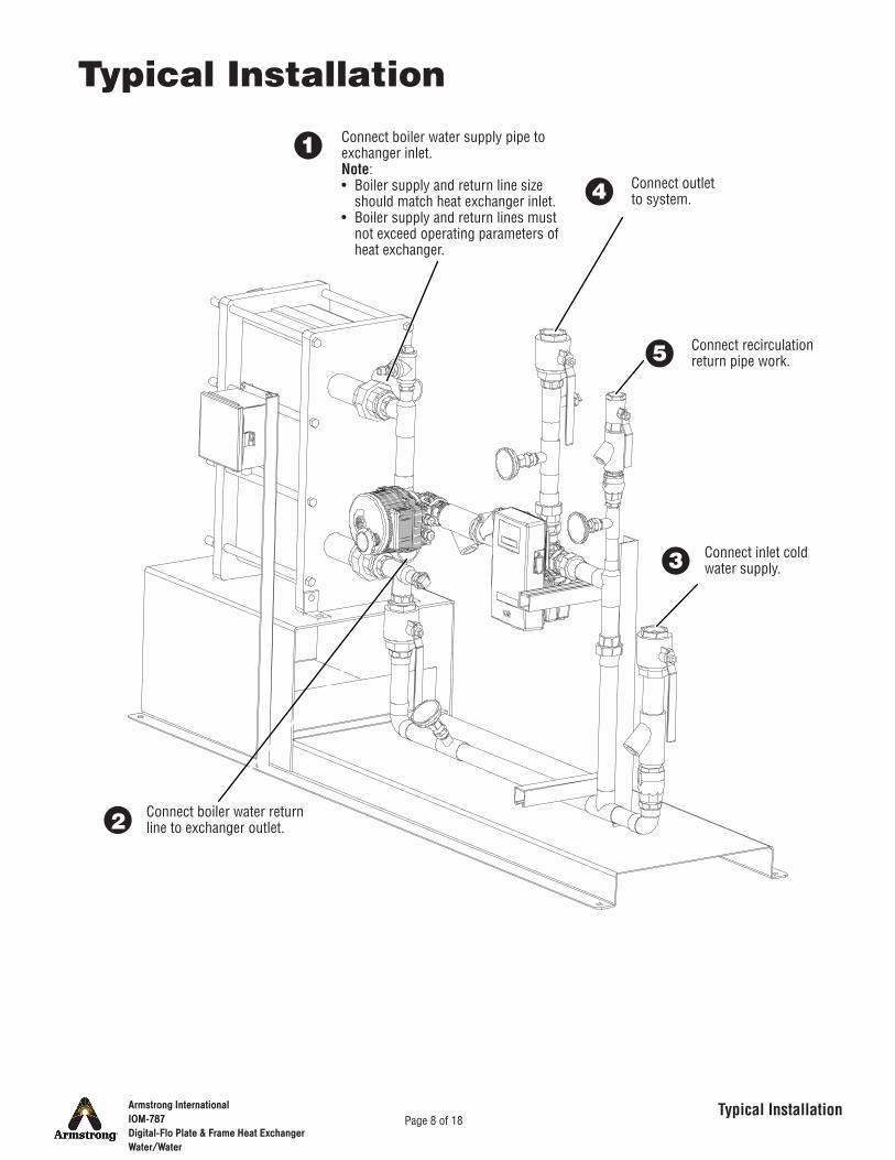
Typical Installation
Connect boiler water supply pipe to exchanger inlet.Note:• Boiler supply and return line size
should match heat exchanger inlet.• Boiler supply and return lines must
not exceed operating parameters of heat exchanger.
1
2
3
4
5
Connect boiler water return line to exchanger outlet.
Connect inlet cold water supply.
Connect outlet to system.
Connect recirculation return pipe work.
Armstrong InternationalIOM-787Digital-Flo Plate & Frame Heat ExchangerWater/Water
Page 9 of 18Commissioning
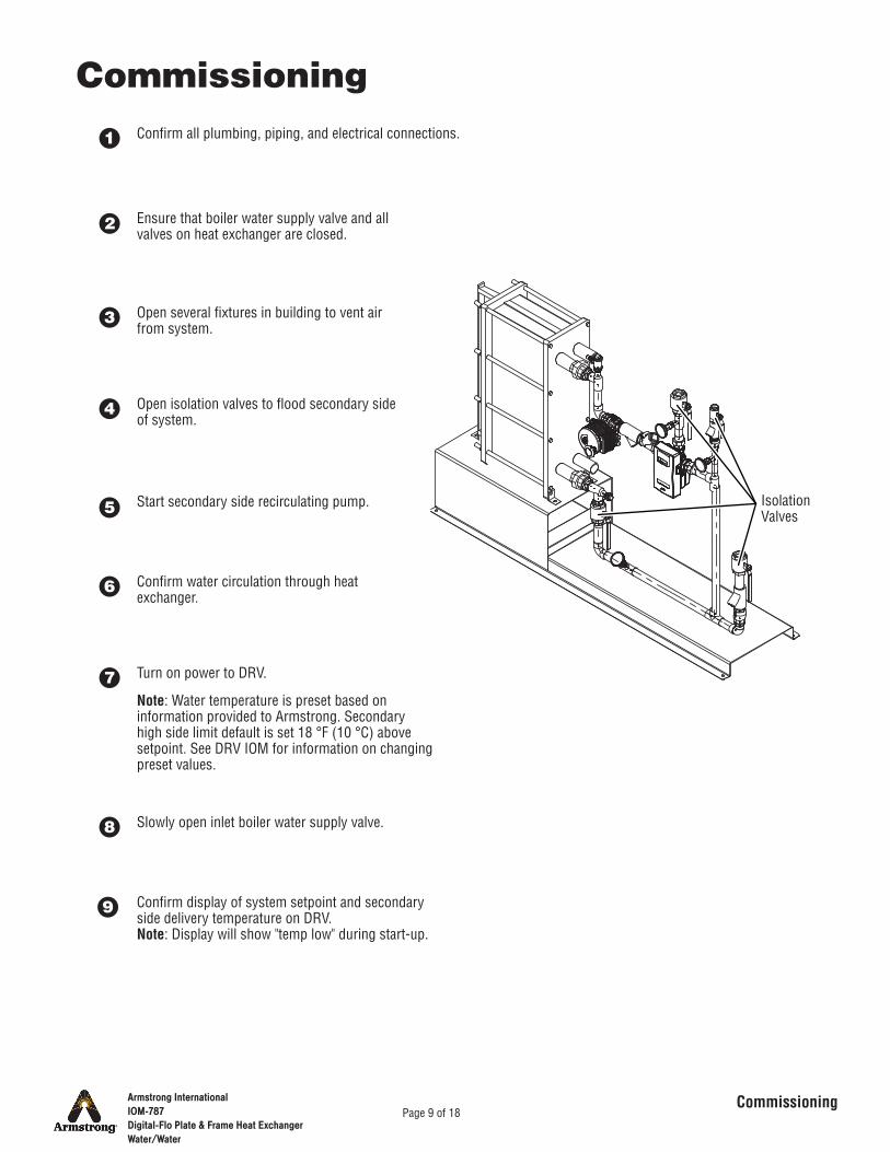
CommissioningConfirm all plumbing, piping, and electrical connections.
Ensure that boiler water supply valve and all valves on heat exchanger are closed.
Open several fixtures in building to vent air from system.
Open isolation valves to flood secondary side of system.
Turn on power to DRV.
Start secondary side recirculating pump.
Confirm water circulation through heat exchanger.
Slowly open inlet boiler water supply valve.
Confirm display of system setpoint and secondary side delivery temperature on DRV.Note: Display will show "temp low" during start-up.
Note: Water temperature is preset based on information provided to Armstrong. Secondary high side limit default is set 18 °F (10 °C) above setpoint. See DRV IOM for information on changing preset values.
Isolation Valves
1
9
8
7
6
5
4
3
2
Armstrong InternationalIOM-787Digital-Flo Plate & Frame Heat ExchangerWater/Water
Page 10 of 18
Periodic Maintenance
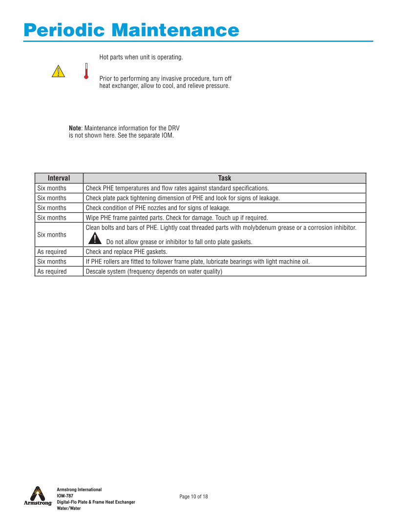
Interval TaskSix months Check PHE temperatures and flow rates against standard specifications.Six months Check plate pack tightening dimension of PHE and look for signs of leakage.Six months Check condition of PHE nozzles and for signs of leakage.Six months Wipe PHE frame painted parts. Check for damage. Touch up if required.
Six monthsClean bolts and bars of PHE. Lightly coat threaded parts with molybdenum grease or a corrosion inhibitor.
Do not allow grease or inhibitor to fall onto plate gaskets.As required Check and replace PHE gaskets.Six months If PHE rollers are fitted to follower frame plate, lubricate bearings with light machine oil.As required Descale system (frequency depends on water quality)
Note: Maintenance information for the DRV is not shown here. See the separate IOM.
Hot parts when unit is operating.
Prior to performing any invasive procedure, turn off heat exchanger, allow to cool, and relieve pressure.

Armstrong InternationalIOM-787Digital-Flo Plate & Frame Heat ExchangerWater/Water
Page 11 of 18
Troubleshooting
Components and water may be hot.
Problem Probable Cause Correction
Secondary side temperature low
Restriction on primary side Confirm that all isolation valves are fully open.Primary side pump not running Restart or troubleshoot pump (If pump is variable-speed,
confirm that speed selection is correct for necessary flow and discharge pressure.)
Primary side water temperature too low
Confirm that temperature is set to design spec.
Secondary side check valve failed
Confirm that recirculation line is hot. If not, check for failed check valve (allows cold water to bypass heat exchanger).
Secondary side temperature rises when there is no demand.
Secondary side flow rate < 10 GPM (38 LPM)
1. Confirm that flow rate setting is > 10 GPM (38 LPM).2. Check system for:
• Air locks• Closed valves• Pump failure• Other similar causes
Return temperature is within 2 °F (1.1 °C) of set point
Ensure temperature differential in circuit is ≥ 2 °F (1.1 °C).
Check valve problem 1. Confirm that check valves were installed as designed.2. Ensure proper function of valves.
Water pressure problem 1. Ensure that supply pressure differential is ≤ 20 psi (1.4 bar).2. Confirm that recirc pump is operating.
Flow restriction Check for:• Air locks• Closed valves• Clogged filters• Other restrictions
DRV fault See DRV IOM.
Secondary side system temperature fluctuates > ± 5 °F (2.8 °C)
Unequal supply pressures on secondary side
Balance pressures.
Secondary side flow restriction Check for:• Air locks• Closed valves• Clogged filters• Other restrictions
Excessive supply temperature differential
Confirm that differentials between set point and hot and cold inlet supplies to DRV are ≥ 10 °F (5.6 °C).
DRV fault See DRV IOM.Primary side inlet temperature fluctuating
1. Confirm that connections are as designed (no cross connections).2. Confirm that bypass is not open.
Demand exceeds capacity of unit Reduce demand.
Note: For problems exclusive to the DRV controller, see that IOM.
Armstrong InternationalIOM-787Digital-Flo Plate & Frame Heat ExchangerWater/Water
Page 12 of 18
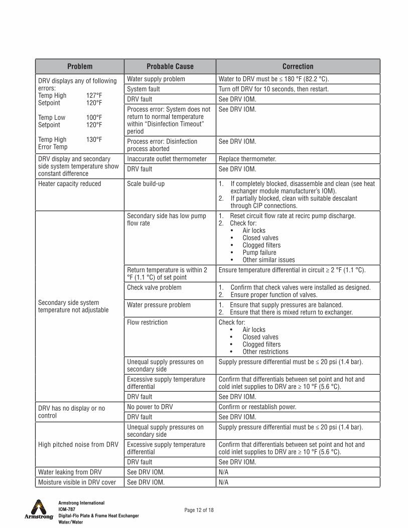
Problem Probable Cause Correction
DRV displays any of following errors:Temp High 127°FSetpoint 120°F
Temp Low 100°FSetpoint 120°F
Temp High 130°FError Temp
Water supply problem Water to DRV must be ≤ 180 °F (82.2 °C).System fault Turn off DRV for 10 seconds, then restart.DRV fault See DRV IOM.Process error: System does not return to normal temperature within “Disinfection Timeout” period
See DRV IOM.
Process error: Disinfection process aborted
See DRV IOM.
DRV display and secondary side system temperature show constant difference
Inaccurate outlet thermometer Replace thermometer.DRV fault See DRV IOM.
Heater capacity reduced Scale build-up 1. If completely blocked, disassemble and clean (see heat exchanger module manufacturer’s IOM).
2. If partially blocked, clean with suitable descalant through CIP connections.
Secondary side system temperature not adjustable
Secondary side has low pump flow rate
1. Reset circuit flow rate at recirc pump discharge.2. Check for:
• Air locks• Closed valves• Clogged filters• Pump failure• Other similar issues
Return temperature is within 2 °F (1.1 °C) of set point
Ensure temperature differential in circuit ≥ 2 °F (1.1 °C).
Check valve problem 1. Confirm that check valves were installed as designed.2. Ensure proper function of valves.
Water pressure problem 1. Ensure that supply pressures are balanced.2. Ensure that there is mixed return to exchanger.
Flow restriction Check for:• Air locks• Closed valves• Clogged filters• Other restrictions
Unequal supply pressures on secondary side
Supply pressure differential must be ≤ 20 psi (1.4 bar).
Excessive supply temperature differential
Confirm that differentials between set point and hot and cold inlet supplies to DRV are ≥ 10 °F (5.6 °C).
DRV fault See DRV IOM.
DRV has no display or no control
No power to DRV Confirm or reestablish power.DRV fault See DRV IOM.
High pitched noise from DRV
Unequal supply pressures on secondary side
Supply pressure differential must be ≤ 20 psi (1.4 bar).
Excessive supply temperature differential
Confirm that differentials between set point and hot and cold inlet supplies to DRV are ≥ 10 °F (5.6 °C).
DRV fault See DRV IOM.Water leaking from DRV See DRV IOM. N/AMoisture visible in DRV cover See DRV IOM. N/A
Armstrong InternationalIOM-787Digital-Flo Plate & Frame Heat ExchangerWater/Water
Page 13 of 18
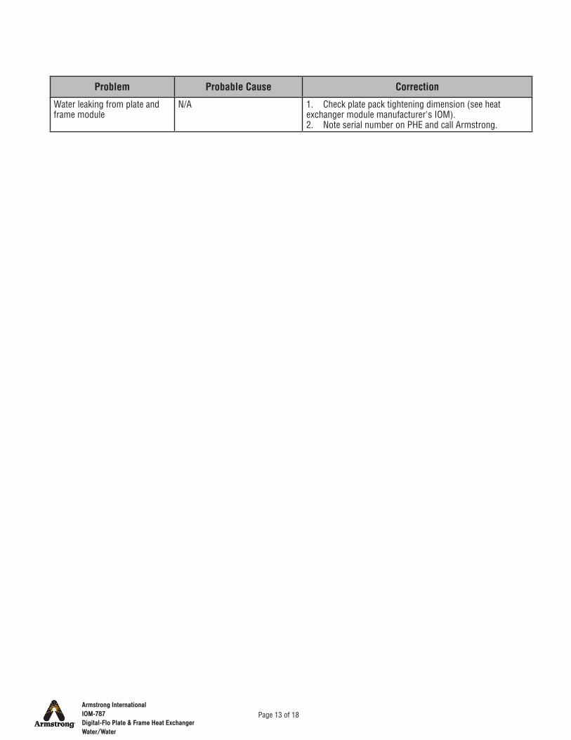
Problem Probable Cause Correction
Water leaking from plate and frame module
N/A 1. Check plate pack tightening dimension (see heat exchanger module manufacturer's IOM).2. Note serial number on PHE and call Armstrong.
Armstrong InternationalIOM-787Digital-Flo Plate & Frame Heat ExchangerWater/Water
Page 14 of 18
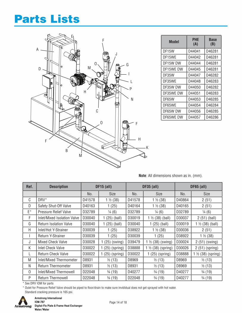
Parts Lists
Ref. Description DF15 (all) DF35 (all) DF65 (all)
No. Size No. Size No. SizeC DRV* D41578 1 ½ (38) D41578 1 ½ (38) D40864 2 (51)D Safety Shut-Off Valve D40163 1 (25) D40164 1 ½ (38) D40165 2 (51)E* Pressure Relief Valve D32789 ¼ (6) D32789 ¼ (6) D32789 ¼ (6)F Inlet/Mixed Isolation Valve D30040 1 (25) (ball) D30019 1 ½ (38) (ball) D30037 2 (51) (ball)G Return Isolation Valve D30040 1 (25) (ball) D30040 1 (25) (ball) D30019 1 ½ (38) (ball)H Inlet/Hot Y-Strainer D30039 1 (25) D38922 1 ½ (38) D30036 2 (51)I Return Y-Strainer D30039 1 (25) D30039 1 (25) D38922 1 ½ (38)J Mixed Check Valve D30028 1 (25) (swing) D39479 1 ½ (38) (swing) D30024 2 (51) (swing)K Inlet Check Valve D30022 1 (25) (spring) D38888 1 ½ (38) (spring) D30026 2 (51) (spring)L Return Check Valve D30022 1 (25) (spring) D30022 1 (25) (spring) D38888 1 ½ (38) (spring)M Inlet/Mixed Thermometer D8931 ½ (13) D8969 ½ (13) D8969 ½ (13)N Return Thermometer D8931 ½ (13) D8931 ½ (13) D8969 ½ (13)O Inlet/Mixed Thermowell D22048 ¾ (19) D40277 ¾ (19) D40277 ¾ (19)P Return Thermowell D22048 ¾ (19) D22048 ¾ (19) D40277 ¾ (19)
Model PHE (A)
Base (B)
DF15W D44041 D46281DF15WE D44042 D46281DF15W DW D44044 D46281DF15WE DW D44045 D46281DF35W D44047 D46282DF35WE D44048 D46283DF35W DW D44050 D46282DF35WE DW D44051 D46283DF65W D44053 D46285DF65WE D44054 D46284DF65W DW D44056 D46285DF65WE DW D44057 D46286
A
M
L
K
J
I
H
G
F
E
D
C
B
N
O
Note: All dimensions shown as in. (mm).
O
P
M
H
F
F
* See DRV IOM for parts* Oulet for Pressure Relief Valve should be piped to floor/drain to make sure invididual does not get sprayed with hot water. Standard cracking pressure is 165 psi.
Armstrong InternationalIOM-787Digital-Flo Plate & Frame Heat ExchangerWater/Water
Page 15 of 18
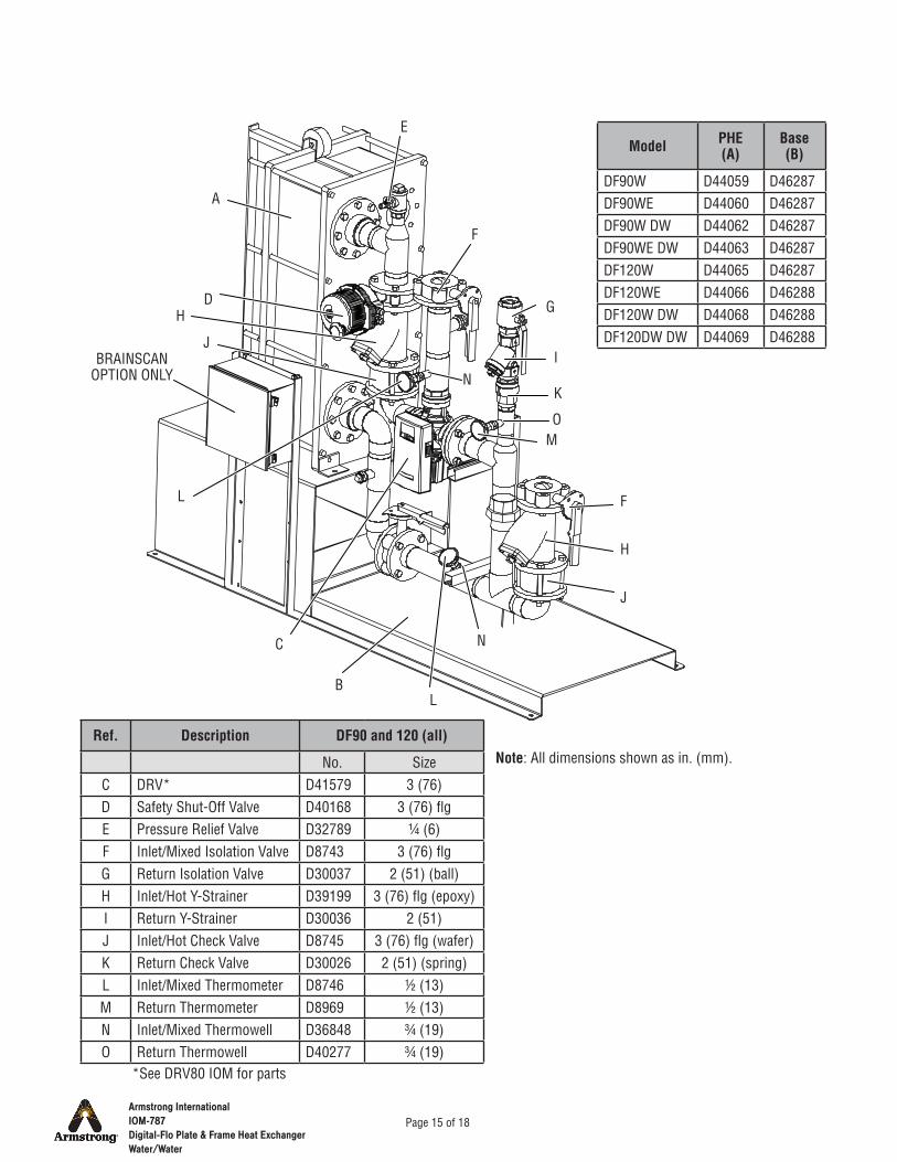
Model PHE (A)
Base (B)
DF90W D44059 D46287DF90WE D44060 D46287DF90W DW D44062 D46287DF90WE DW D44063 D46287DF120W D44065 D46287DF120WE D44066 D46288DF120W DW D44068 D46288DF120DW DW D44069 D46288
Ref. Description DF90 and 120 (all)
No. SizeC DRV* D41579 3 (76)D Safety Shut-Off Valve D40168 3 (76) flgE Pressure Relief Valve D32789 ¼ (6)F Inlet/Mixed Isolation Valve D8743 3 (76) flgG Return Isolation Valve D30037 2 (51) (ball)H Inlet/Hot Y-Strainer D39199 3 (76) flg (epoxy)I Return Y-Strainer D30036 2 (51)J Inlet/Hot Check Valve D8745 3 (76) flg (wafer)K Return Check Valve D30026 2 (51) (spring)L Inlet/Mixed Thermometer D8746 ½ (13)M Return Thermometer D8969 ½ (13)N Inlet/Mixed Thermowell D36848 ¾ (19)O Return Thermowell D40277 ¾ (19)
A
M
L
K
J
I
H
G
F
E
D
C
B
N
O
Note: All dimensions shown as in. (mm).
J
N
L
F
H
BRAINSCANOPTION ONLY
*See DRV80 IOM for parts
Armstrong InternationalIOM-787Digital-Flo Plate & Frame Heat ExchangerWater/Water
Page 16 of 18
Armstrong Hot Water, Inc. ("Armstrong") warrants to the original user of those products supplied by it and used in the service and in the manner for which they are intended, that such products shall be free from defects in material and workmanship for a period of two (2) years from the date of installation, but not longer than 27 months from the date of shipment from the factory [unless a special warranty period applies, as listed below]. This warranty does not extend to any product that has been subject to misuse, neglect, or alteration after shipment from the Armstrong factory. Except as may be expressly provided in a written agreement between Armstrong and the user, which is signed by both parties, Armstrong DOES NOT MAKE ANY OTHER REPRESENTATIONS OR WARRANTIES, EXPRESS OR IMPLIED, INCLUDING, BUT NOT LIMITED TO, ANY IMPLIED WARRANTY OF MERCHANTABILITY OR ANY IMPLIED WARRANTY OF FITNESS FOR A PARTICULAR PURPOSE. The sole and exclusive remedy with respect to the above limited warranty or with respect to any other claim relating to the products or to defects or any condition or use of the products supplied by Armstrong, however caused, and whether such claim is based upon warranty, contract, negligence, strict liability, or any other basis or theory, is limited to Armstrong's repair or replacement of the part or product, excluding any labor or any other cost to remove or install said part or product, or, at Armstrong's option, to repayment of the purchase price. As a condition of enforcing any rights or remedies relating to Armstrong products, notice of any warranty or other claim relating to the products must be given in writing to Armstrong: (i) within 30 days of last day of the applicable warranty period, or (ii) within 30 days of the date of the manifestation of the condition or occurrence giving rise to the claim, whichever is earlier. IN NO EVENT SHALL ARMSTRONG BE LIABLE FOR SPECIAL, DIRECT, INDIRECT, INCIDENTAL OR CONSEQUENTIAL DAMAGES, INCLUDING, BUT NOT LIMITED TO, LOSS OF USE OR PROFITS OR INTERRUPTION OF BUSINESS. The Limited Warranty and Remedy terms herein apply notwithstanding any contrary terms in any purchase order or form submitted or issued by any user, purchaser, or third party and all such contrary terms shall be deemed rejected by Armstrong.
DRV warranty: products shall be free from defect in material and workmanship for a period of five (5) years from the date of shipment from the factory. This warranty does not extend to any product that has been subject to misuse, neglect, or alteration after shipment from the Armstrong factory. Except as may be expressly provided in a written agreement between Armstrong and the user, which is signed by both parties, Armstrong DOES NOT MAKE ANY OTHER REPRESENTATIONS OR WARRANTIES, EXPRESSED OR IMPLIED, INCLUDING, BUT NOT LIMITED TO, ANY IMPLIED WARRANTY OF MERCHANTABILITY OR ANY IMPLIED WARRANTY OF FITNESS FOR A PARTICULAR PURPOSE. The sole and exclusive remedy with respect to the above limited warranty or with respect to any other claim relating to the products or to defects or any other condition or use of the products supplied by Armstrong, however caused, and whether such claim is based upon warranty, contract, negligence, strict liability, or any other basis or theory, is limited to Armstrong’s repair or replacement of the part or product, excluding any labor or any cost to remove or install said part or product, or, at Armstrong’s option, to repayment of the purchase price. As a condition of enforcing any rights or remedies relating to Armstrong products, notice of any warranty or other claim relating to the products must be given in writing to Armstrong: (i) within 30 days of last day of the appliance warranty period, or (ii) within 30 days of the date of the manifestation of the condition or occurrence giving rise to the claim, whichever is earlier. IN NO EVENT SHALL ARMSTRONG BE LIABLE FOR SPECIAL, DIRECT, INDIRECT, INCIDENTAL OR CONSEQUENTIAL DAMAGES, INCLUDING, BUT NOT LIMITED TO, LOSS OF USE OR PROFITS OR INTERRUPTION OF BUSINESS. The Limited Warranty and Remedy terms herein apply notwithstanding any contrary terms in any purchase order or form submitted or issued by any user, purchaser, or third party and all such contrary terms shall be deemed rejected by Armstrong.
Limited Warranty and Remedy

Armstrong InternationalIOM-787Digital-Flo Plate & Frame Heat ExchangerWater/Water
Page 17 of 18
Notes

Armstrong InternationalIOM-787Digital-Flo Plate & Frame Heat ExchangerWater/Water
Page 18 of 18
Notes