digital electronic module 2ro no/nc dc24..48v/5a · pdf filedigital electronic module 2ro...
TRANSCRIPT
�Digital electronic module 2RO NO/NC DC24..48V/5A AC24..230V/5A (6ES7132-4HB12-0AB0)�
SIMATIC
ET 200S distributed I/ODigital electronic module 2RO NO/NC DC24..48V/5A AC24..230V/5A (6ES7132-4HB12-0AB0)
Manual
03/2010 A5E02773653-01
Preface
Properties
1
Parameters
2
Diagnostics
3
Legal information
Legal information Warning notice system
This manual contains notices you have to observe in order to ensure your personal safety, as well as to prevent damage to property. The notices referring to your personal safety are highlighted in the manual by a safety alert symbol, notices referring only to property damage have no safety alert symbol. These notices shown below are graded according to the degree of danger.
DANGER indicates that death or severe personal injury will result if proper precautions are not taken.
WARNING indicates that death or severe personal injury may result if proper precautions are not taken.
CAUTION with a safety alert symbol, indicates that minor personal injury can result if proper precautions are not taken.
CAUTION without a safety alert symbol, indicates that property damage can result if proper precautions are not taken.
NOTICE indicates that an unintended result or situation can occur if the corresponding information is not taken into account.
If more than one degree of danger is present, the warning notice representing the highest degree of danger will be used. A notice warning of injury to persons with a safety alert symbol may also include a warning relating to property damage.
Qualified Personnel The product/system described in this documentation may be operated only by personnel qualified for the specific task in accordance with the relevant documentation for the specific task, in particular its warning notices and safety instructions. Qualified personnel are those who, based on their training and experience, are capable of identifying risks and avoiding potential hazards when working with these products/systems.
Proper use of Siemens products Note the following:
WARNING Siemens products may only be used for the applications described in the catalog and in the relevant technical documentation. If products and components from other manufacturers are used, these must be recommended or approved by Siemens. Proper transport, storage, installation, assembly, commissioning, operation and maintenance are required to ensure that the products operate safely and without any problems. The permissible ambient conditions must be adhered to. The information in the relevant documentation must be observed.
Trademarks All names identified by ® are registered trademarks of the Siemens AG. The remaining trademarks in this publication may be trademarks whose use by third parties for their own purposes could violate the rights of the owner.
Disclaimer of Liability We have reviewed the contents of this publication to ensure consistency with the hardware and software described. Since variance cannot be precluded entirely, we cannot guarantee full consistency. However, the information in this publication is reviewed regularly and any necessary corrections are included in subsequent editions.
Siemens AG Industry Sector Postfach 48 48 90026 NÜRNBERG GERMANY
A5E02773653-01 Ⓟ 02/2010
Copyright © Siemens AG 2010. Technical data subject to change
Digital electronic module 2RO NO/NC DC24..48V/5A AC24..230V/5A (6ES7132-4HB12-0AB0) Manual, 03/2010, A5E02773653-01 3
Preface
Purpose of the manual This manual supplements the ET 200S Distributed I/O System Operating Instructions. General functions for the ET 200S are described in the ET 200S Distributed I/O System Operating Instructions (http://support.automation.siemens.com/WW/view/en/1144348). The information in this document along with the operating instructions enables you to commission the ET 200S.
Basic knowledge requirements To understand these operating instructions you should have general knowledge of automation engineering.
Scope of the manual This manual applies to this ET 200S module. It describes the components that are valid at the time of publication.
Recycling and disposal Thanks to the fact that it is low in contaminants, this ET 200S module is recyclable. For environmentally compliant recycling and disposal of your electronic waste, please contact a company certified for the disposal of electronic waste.
Additional support If you have any questions relating to the products described in this manual and do not find the answers in this document, please contact your local Siemens representative (http://www.siemens.com/automation/partners). A guide to the technical documentation for the various SIMATIC products and systems is available on the Internet. (http://www.siemens.com/simatic-docu). The online catalog and ordering systems are available on the Internet (http://www.siemens.com/automation/mall).
Training center We offer courses to help you get started with the ET 200S and the SIMATIC S7 automation system. Please contact your regional training center or the central training center in D -90327, Nuremberg, Germany (http://www.siemens.com/sitrain).
Preface
Digital electronic module 2RO NO/NC DC24..48V/5A AC24..230V/5A (6ES7132-4HB12-0AB0) 4 Manual, 03/2010, A5E02773653-01
Technical Support You can contact Technical Support for all Industry Automation products by means of the Internet Web form for the Support Request (http://www.siemens.com/automation/csi_en_WW/support_request). Additional information about Siemens Technical Support is available on the Internet (http://www.siemens.com/automation/csi_en_WW/service).
Service & Support on the Internet In addition to our documentation, we offer a comprehensive knowledge base on the Internet (http://www.siemens.com/automation/csi_en_WW/support). There you will find: ● Our Newsletter, which constantly provides you with the latest information about your
products. ● The right documentation for you using our Service & Support search engine. ● The bulletin board, a worldwide knowledge exchange for users and experts. ● Your local contact for Automation & Drives in our contact database. ● Information about on-site services, repairs, spare parts, and lots more.

Digital electronic module 2RO NO/NC DC24..48V/5A AC24..230V/5A (6ES7132-4HB12-0AB0) Manual, 03/2010, A5E02773653-01 5
Table of contents
Preface ...................................................................................................................................................... 3 1 Properties .................................................................................................................................................. 7
1.1 Digital electronic module 2RO NO/NC DC24..48V/5A AC24..230V/5A (6ES7132-4HB12-0AB0)................................................................................................................7
2 Parameters .............................................................................................................................................. 13 2.1 Parameters...................................................................................................................................13
3 Diagnostics .............................................................................................................................................. 15 3.1 Diagnostics using LED display.....................................................................................................15
Index........................................................................................................................................................ 17
Table of contents
Digital electronic module 2RO NO/NC DC24..48V/5A AC24..230V/5A (6ES7132-4HB12-0AB0) 6 Manual, 03/2010, A5E02773653-01
Digital electronic module 2RO NO/NC DC24..48V/5A AC24..230V/5A (6ES7132-4HB12-0AB0) Manual, 03/2010, A5E02773653-01 7
Properties 11.1 Digital electronic module 2RO NO/NC DC24..48V/5A
AC24..230V/5A (6ES7132-4HB12-0AB0)
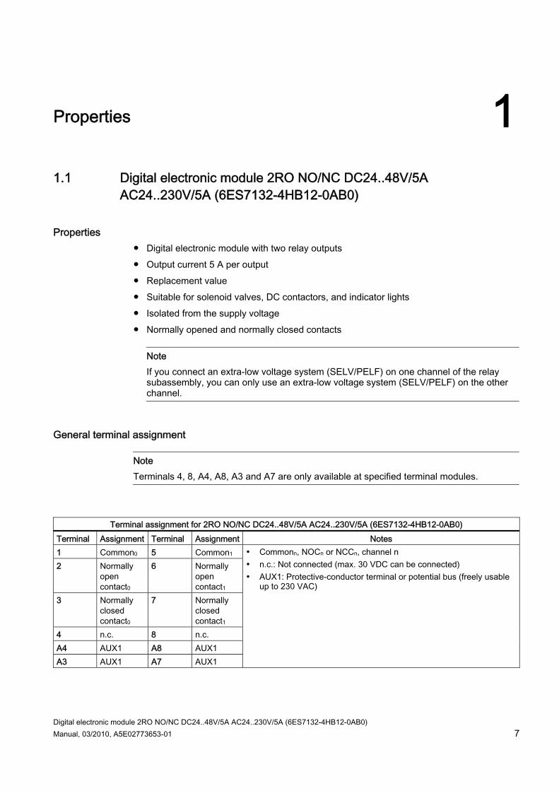
Properties ● Digital electronic module with two relay outputs ● Output current 5 A per output ● Replacement value ● Suitable for solenoid valves, DC contactors, and indicator lights ● Isolated from the supply voltage ● Normally opened and normally closed contacts
Note If you connect an extra-low voltage system (SELV/PELF) on one channel of the relay subassembly, you can only use an extra-low voltage system (SELV/PELF) on the other channel.
General terminal assignment
Note Terminals 4, 8, A4, A8, A3 and A7 are only available at specified terminal modules.
Terminal assignment for 2RO NO/NC DC24..48V/5A AC24..230V/5A (6ES7132-4HB12-0AB0)
Terminal Assignment Terminal Assignment Notes 1 Common0 5 Common1 2 Normally
open contact0
6 Normally open contact1
3 Normally closed contact0
7 Normally closed contact1
4 n.c. 8 n.c. A4 AUX1 A8 AUX1 A3 AUX1 A7 AUX1
Commonn, NOCn or NCCn, channel n n.c.: Not connected (max. 30 VDC can be connected) AUX1: Protective-conductor terminal or potential bus (freely usable
up to 230 VAC)

Properties 1.1 Digital electronic module 2RO NO/NC DC24..48V/5A AC24..230V/5A (6ES7132-4HB12-0AB0)
Digital electronic module 2RO NO/NC DC24..48V/5A AC24..230V/5A (6ES7132-4HB12-0AB0) 8 Manual, 03/2010, A5E02773653-01
Usable terminal modules
Usable terminal modules for 2RO NO/NC DC24..48V/5A AC24..230V/5A (6ES7132-4HB12-0AB0) TM-E15C26-A1 (6ES7193-4CA50-0AA0)
TM-E15C24-A1 (6ES7193-4CA30-0AA0)
TM-E15C24-01 (6ES7193-4CB30-0AA0)
TM-E15C23-01 (6ES7193-4CB10-0AA0)
Spring terminal
TM-E15S26-A1 (6ES7193-4CA40-0AA0)
TM-E15S24-A1 (6ES7193-4CA20-0AA0)
TM-E15S24-01 (6ES7193-4CB20-0AA0)
TM-E15S23-01 (6ES7193-4CB00-0AA0)
Screw-type terminal
TM-E15N26-A1 (6ES7193-4CA80-0AA0)
TM-E15N24-A1 (6ES7193-4CA70-0AA0)
TM-E15N24-01 (6ES7193-4CB70-0AA0)
TM-E15N23-01 (6ES7193-4CB60-0AA0)
Fast Connect
Block diagram
Figure 1-1 Block diagram of the 2RO NO/NC DC24..48V/5A AC24..230V/5A
Properties 1.1 Digital electronic module 2RO NO/NC DC24..48V/5A AC24..230V/5A (6ES7132-4HB12-0AB0)
Digital electronic module 2RO NO/NC DC24..48V/5A AC24..230V/5A (6ES7132-4HB12-0AB0) Manual, 03/2010, A5E02773653-01 9
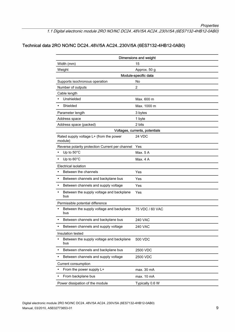
Technical data 2RO NO/NC DC24..48V/5A AC24..230V/5A (6ES7132-4HB12-0AB0)
Dimensions and weight Width (mm) 15 Weight Approx. 50 g
Module-specific data Supports isochronous operation No Number of outputs 2 Cable length Unshielded Max. 600 m
Shielded Max. 1000 m
Parameter length 3 bytes Address space 1 byte Address space (packed) 2 bits
Voltages, currents, potentials Rated supply voltage L+ (from the power module)
24 VDC
Reverse polarity protection Current per channel Yes Up to 50°C Max. 5 A
Up to 60°C Max. 4 A
Electrical isolation Between the channels Yes
Between channels and backplane bus Yes
Between channels and supply voltage Yes
Between the supply voltage and backplane bus
Yes
Permissible potential difference Between the supply voltage and backplane
bus 75 VDC / 60 VAC
Between channels and backplane bus 240 VAC
Between channels and supply voltage 240 VAC
Insulation tested Between the supply voltage and backplane
bus 500 VDC
Between channels and backplane bus 2500 VDC
Between channels and supply voltage 2500 VDC
Current consumption From the power supply L+ max. 30 mA
From backplane bus max. 10 mA
Power dissipation of the module Typically 0.6 W
Properties 1.1 Digital electronic module 2RO NO/NC DC24..48V/5A AC24..230V/5A (6ES7132-4HB12-0AB0)
Digital electronic module 2RO NO/NC DC24..48V/5A AC24..230V/5A (6ES7132-4HB12-0AB0) 10 Manual, 03/2010, A5E02773653-01
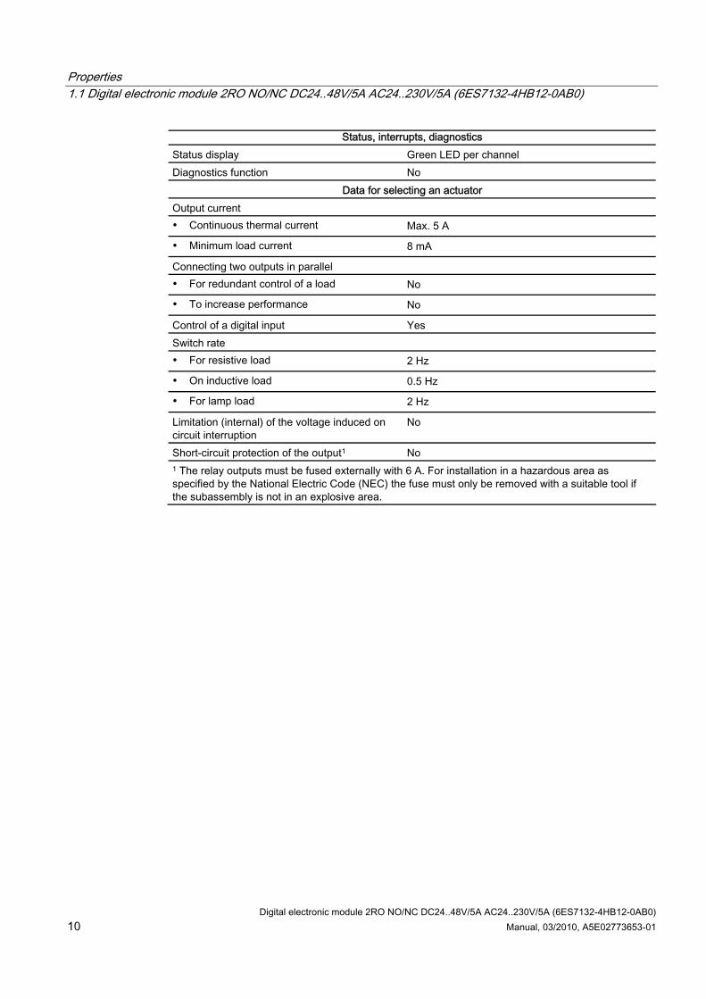
Status, interrupts, diagnostics Status display Green LED per channel Diagnostics function No
Data for selecting an actuator Output current Continuous thermal current Max. 5 A
Minimum load current 8 mA
Connecting two outputs in parallel For redundant control of a load No
To increase performance No
Control of a digital input Yes Switch rate For resistive load 2 Hz
On inductive load 0.5 Hz
For lamp load 2 Hz
Limitation (internal) of the voltage induced on circuit interruption
No
Short-circuit protection of the output1 No 1 The relay outputs must be fused externally with 6 A. For installation in a hazardous area as specified by the National Electric Code (NEC) the fuse must only be removed with a suitable tool if the subassembly is not in an explosive area.
Properties 1.1 Digital electronic module 2RO NO/NC DC24..48V/5A AC24..230V/5A (6ES7132-4HB12-0AB0)
Digital electronic module 2RO NO/NC DC24..48V/5A AC24..230V/5A (6ES7132-4HB12-0AB0) Manual, 03/2010, A5E02773653-01 11
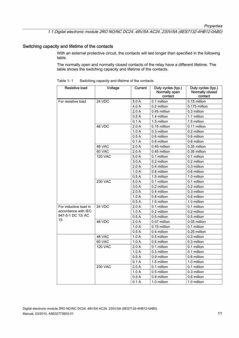
Switching capacity and lifetime of the contacts With an external protective circuit, the contacts will last longer than specified in the following table. The normally open and normally closed contacts of the relay have a different lifetime. The table shows the switching capacity and lifetime of the contacts.
Table 1- 1 Switching capacity and lifetime of the contacts
Resistive load Voltage Current Duty cycles (typ.) Normally open
contact
Duty cycles (typ.) Normally closed
contact 5.0 A 0.1 million 0.15 million 4.0 A 0.2 million 0.175 million 2.0 A 0.45 million 0.3 million 0.5 A 1.4 million 1.1 million
24 VDC
0.1 A 1.5 million 1.5 million 2.0 A 0.15 million 0.11 million 1.0 A 0.3 million 0.2 million 0.5 A 0.6 million 0.6 million
48 VDC
0.1 A 0.8 million 0.6 million 48 VAC 2.0 A 0.45 million 0.35 million 60 VAC 2.0 A 0.45 million 0.35 million
5.0 A 0.1 million 0.1 million 3.0 A 0.2 million 0.2 million 2.0 A 0.4 million 0.3 million 1.0 A 0.8 million 0.6 million
120 VAC
0.5 A 1.5 million 1.0 million 5.0 A 0.1 million 0.1 million 3.0 A 0.2 million 0.2 million 2.0 A 0.4 million 0.3 million 1.0 A 0.8 million 0.6 million
For resistive load
230 VAC
0.5 A 1.5 million 1.0 million 2.0 A 0.1 million 0.1 million 1.0 A 0.2 million 0.2 million
24 VDC
0.5 A 0.5 million 0.5 million 2.0 A 0.07 million 0.05 million 1.0 A 0.15 million 0.1 million
For inductive load in accordance with IEC 947-5-1 DC 13/ AC 15 48 VDC
0.5 A 0.4 million 0.25 million 48 VAC 1.0 A 0.5 million 0.3 million 60 VAC 1.0 A 0.5 million 0.3 million
2.0 A 0.1 million 0.1 million 1.0 A 0.3 million 0.1 million 0.5 A 0.9 million 0.6 million
120 VAC
0.1 A 1.5 million 1.0 million 2.0 A 0.1 million 0.1 million 1.0 A 0.5 million 0.3 million 0.5 A 0.9 million 0.6 million
230 VAC
0.1 A 1.0 million 1.0 million

Properties 1.1 Digital electronic module 2RO NO/NC DC24..48V/5A AC24..230V/5A (6ES7132-4HB12-0AB0)
Digital electronic module 2RO NO/NC DC24..48V/5A AC24..230V/5A (6ES7132-4HB12-0AB0) 12 Manual, 03/2010, A5E02773653-01

Digital electronic module 2RO NO/NC DC24..48V/5A AC24..230V/5A (6ES7132-4HB12-0AB0) Manual, 03/2010, A5E02773653-01 13
Parameters 22.1 Parameters
This table shows the parameters for digital output modules:
Table 2- 1 Parameters for digital output modules
2RO NO NC DC24..48V/5A AC24..230V/5A
Range of values Default setting Applicability
Reaction to CPU-/master-STOP Substitute a value Keep last value
Substitute a value Module
Substitute value * "0" "1"
"0" Channel
* If the interface module or COMPACT module becomes deenergized, the digital output modules will not produce substitute values. Output value = 0.

Parameters 2.1 Parameters
Digital electronic module 2RO NO/NC DC24..48V/5A AC24..230V/5A (6ES7132-4HB12-0AB0) 14 Manual, 03/2010, A5E02773653-01

Digital electronic module 2RO NO/NC DC24..48V/5A AC24..230V/5A (6ES7132-4HB12-0AB0) Manual, 03/2010, A5E02773653-01 15
Diagnostics 33.1 Diagnostics using LED display
LED display
1
① Status display for output status (green)
Status and error displays
Event (LEDs) 1 5
Cause Remedy
On Output on channel 0 activated. — On Output on channel 1 activated. —
Diagnostics 3.1 Diagnostics using LED display
Digital electronic module 2RO NO/NC DC24..48V/5A AC24..230V/5A (6ES7132-4HB12-0AB0) 16 Manual, 03/2010, A5E02773653-01
Digital electronic module 2RO NO/NC DC24..48V/5A AC24..230V/5A (6ES7132-4HB12-0AB0) Manual, 03/2010, A5E02773653-01 17
Index
B Basic knowledge requirements, 3
D Digital electronic module 2RO NO/NC DC24..48V/5A AC24..230V/5A
Block diagram, 8 Properties, 7 Switching capacity and lifetime of the contacts, 11 Technical data, 9 Terminal assignment, 7
Disposal, 3
I Internet
Service & Support, 4
L LED display, 15
P Parameters
for digital output modules, 13
R Recycling, 3
S Scope
Manual, 3 Service & Support, 4
T Technical Support, 4 Training Center, 3
Index
Digital electronic module 2RO NO/NC DC24..48V/5A AC24..230V/5A (6ES7132-4HB12-0AB0) 18 Manual, 03/2010, A5E02773653-01