digital clamp-on meter instruction...
TRANSCRIPT

270Digital Clamp-onMeter Instruction Manual

A. INTRODUCTION
1. Congratulations!!Thank you for purchasing TPI products. The 270 is easyto use and is built to last. It is backed by a 3 year limit-ed warranty. Please remember to complete and returnyour product warranty registration card.
2. Product DescriptionThe slim design 270 is a hand-held, autorangingclamp-on DMM. Extra large numerals, min/max, capaci-tance, DC microamps and duty cycle are just a few of thefeatures of the 270. An affordable choice, the 270 offersmeasurements in all basic electrical functions with addi-tional advanced features like non-contact voltage.
The 270 comes complete with the following accessories:
Carrying PouchTest Lead SetTemperature ProbeInstruction ManualBattery & Fuse
TABLE OF CONTENTS
A. INTRODUCTION1. Congratulations ..........................32. Product Description ....................33. Declaration of Conformity ..........4
B. SAFETY CONSIDERATIONS ..............5
C. TECHNICAL DATA1. Features and Benefits..................62. Product Applications ..................73. Specifications..............................8
D. MEASUREMENT TECHNIQUES1. Controls and Functions ............122. Step by Step Procedures: ........14
E. OTHER FEATURES ..........................24
F. APPLICATION NOTES ......................29
G. TROUBLE SHOOTING GUIDE ..........34
H. MAINTENANCE ................................35
I. ACCESSORIES ................................36
2 3

B. SAFETY CONSIDERATIONS
WARNING: Please follow manufacturers test procedures whenever possible. Do not attempt tomeasure unknown voltages or components until a complete understanding of the circuit is obtained.
GENERAL GUIDELINESALWAYS
• Test the 270 before using it to make sure it is operating properly.
• Inspect the test leads before using to make sure thereare no breaks or shorts.
• Double check all connections before testing.• Have someone check on you periodically if
working alone.• Have a complete understanding of the circuit
being measured.• Disconnect power to circuit, then connect test leads to
the 270, then to circuit being measured.
NEVER• Attempt to measure unknown high voltages.• Attempt to measure DC microamps with the meter in
parallel to the circuit.• Connect the test leads to a live circuit before
setting up the instrument.• Touch any exposed metal part of the test lead assembly.
3. EC Declaration of ConformityThis is to certify that TPI Model 270 conforms to theprotection requirements of the council directive89/336/EEC, in the approximation of laws of the memberstates relating to Electromagnetic compatibility and73/23/EEC. The Low Voltage Directive by application ofthe following standards:
EN 50081-1 1992 Emissions StandardEN 50082-1 1992 Immunity StandardEN 61010-1 1993 Safety StandardEN 61010-2-031 1995 Safety StandardEN 61010-2-032 1995 Safety Standard
To ensure conformity with these standard, this instru-ment must be operated in accordance with the instruc-tions and specifications given in this manual.
CAUTION: Even though this instrument complies withthe immunity standards, it’s accuracy can be affected by strong radio emissions not covered in the abovestandards. Sources such as hand-held radio trans-ceivers, radio and TV transmitters, vehicle radios andcellular phones generate electromagnetic radiationthat could be induced into the test leads of this instru-ment. Care should be taken to avoid such situations oralternatively, check to make sure that the instrument isnot being influence by these emissions.
CAUTION: Please follow manufacturers test proce-dures whenever possible. Do not attempt to measureunknown voltages or components until a completeunderstanding of the circuit is obtained.
4 5

INTERNATIONAL SYMBOLS
CAUTION: RISK OF ELECTRIC SHOCK
AC (Alternation Current)
DC (Direct Current)
REFER TO INSTRUCTION MANUAL
GROUND
DOUBLE INSULATION
EITHER DC OR AC
C. TECHNICAL DATA
1. Features and BenefitsAgency Meets CE and IEC 1010.Analog Bar Displays rapidly changing inputGraph signals.NCV Non-contact voltage detection. Detect
the presence of voltage without con-tacting the circuit.
P-H Captures min / max peak.MAX/MIN Records Min/Max readings for all
functions and ranges.REL Measurements made are displayed
relative to a stored value.Auto Off Automatically powers off after 30
minutes of inactivity.
2. Product Applications
Perform the following tests and/or measurements withthe 270 and the appropriate function:
HVAC/RDCmV • Thermocouples in furnaces.ACA • Heat anticipator current in thermostats.ACV • Line voltage.ACV or DCV • Control circuit voltage.DCmA • Flame safegaurd control current.OHMS • Compressor winding resistance.OHMS • Continuity of wiring.CAP • Motor start and run capacitors.ACA • Motor and compressor start up current.Hz • Frequency on controls and line voltage.TEMP • Air duct temperatures.ALL • Bar graph to indicate rapid fluctuations.
ELECTRICALACV • Measure line voltage.ACA • Measure line current.OHMS • Continuity of circuit breakers.DCV • Voltage of direct drive DC motors.ACA • Start up current of motors, relays,
contactors and transformers.
ELECTRONICACV • Measure power supply voltage.ACA • Measure power supply current.OHMS • Continuity of circuit breakers and fuses.
6 7

9
3. SpecificationsIEC 1010 Over Voltage:CAT II - 1000VCAT III - 600VPollution Degree 2
Temperature for gauranteed accuracy: 23ºC +5ºC
DC VOLTSRange Res. Accuracy
400mV 0.1mV Impedance:
4V 0.001V +/-(0.5% of reading + 2 digits) 10MW
40V 0.01V Overload Protection:
400V 0.1V 600VDC or AC RMS
600V 1V
(45Hz to 100Hz Frequency Response 400mV Range)AC VOLTS (45Hz to 450Hz Frequency Response All Other Ranges)
Range Res. Accuracy
400mV 0.1mV +/-(1.2% of reading + 5 digits) Impedance:
4V 0.001V +/-(1.2% of reading + 3 digits) 10MW
40V 0.01V Overload Protection:
400V 0.1V +/-(1.5% of reading + 3 digits) 600VDC or AC RMS
600V 1V
8
DC MicroampsRange Res. Accuracy
40uA 0.01mA +/-(0.8% of reading + 2 digits) Overload Protection:
400uA 0.1mA 0.5A / 600V Fusee
*DC microamps are measured with the test leads in series withthe circuit under test.
OHM (Resistance, W)Range Res. Accuracy
400W 0.1W ±(1% of reading +5 digits)4kW 0.001kW ±(1% of reading +2 digits) Overload Protection:
40kW 0.01kW 250VDC or AC RMS
400kW 0.1kW4MW 0.001MW ±(3% of reading +5 digits)40MW 0.01MW ±(3% of reading +10 digits)
Frequency (Hz)Range Res. Accuracy
4.000kHz 0.001kHz ±(1% of reading +2 digits)40.00kHz 0.01kHz400.0kHz 0.1kHz Overload Protection:
4.000MHz 0.001MHz 250VDC or AC RMS
40.00MHz 0.01MHz400.0MHz 0.1MHz
UL 3111 Pending
(45Hz to 100Hz Frequency Response 200A to 400A)
AC AMPS (45Hz to 450Hz Frequency Response Below 200A)
Range Res. Accuracy
40A 0.01A +/-(3.0% of reading + 5 digits)
400A 0.1A e
Warning: Use only correct type and overvoltage category rated test leads. Remove the temperature probe when using the test leads or amp clamp.

Diode TestTest Current Over Load Protection
1.5mA MAX 250 V DC or AC RMS
Continuity BuzzerTest Voltage Threshold Over Load Protection
3V <35W 250 V DC or AC RMS
Non-Contact Voltage (NCV)Detection Range: 24VAC and above
Temperature (K-Type thermocouple)Range Res. Accuracy
-40ºF to 399.9ºF 0.1ºF +(1ºF) 32.0ºF to 120.0ºF + (1%+1.5ºF) -4.0ºF to 31.9ºF+ (1%+1.5ºF) -120.1ºF to 399.9ºF+ (2%+4ºF) -40.0ºF to -3.9ºF
-40ºF to 1000ºF 1ºF +(2ºF) 32.0ºF to 120ºF + (1%+2ºF) -3ºF to 749ºF+ (2%+1.5ºF) 750ºF to 1000ºF+ (2%+4ºF) -40ºF to -4ºF
Overload Protection: 60VDC or 30VAC RMS
**Celsius version of the 270 is available
1110
CapacitanceRange Res. Accuracy
4nF 0.001nF ±(1% of reading +2 digits)40nF 0.01nF400nF 0.1nF Overload Protection:
4mF 0.001mF 500VDC or AC RMS
40mF 0.01mF400mF 0.1uF4mF 0.001mF40mF 0.01mF ±(3% of reading +5 digits)
nF= nanofarad, mF= microfarad, mF= millifarad
GeneralMax Voltage between any 600Vinput and groundFuse Protection (mmA range) 0.5A/600VDisplay Type 4000 Count 41 seg. bargraphOperating Temperature 32ºF to 104ºF (0ºC to 40ºC)Storage Temperature 14ºF to 122ºF (-10ºC to 50ºC)Relative Humidity 80% non-condensingPower Supply 9V (MN1604)Battery Life 80 hrs. typicalSize (H x L x W) 32.5mm x 255mm x 65mm
(1.3in x 10in x 2.5in)Weight 363g (0.8lbs)
Warning: Use only correct type and overvoltage category rated test leads. Remove the temperature probe when using the test leads or amp clamp.
Warning: Use only correct type and overvoltage category rated test leads. Remove the temperature probe when using the test leads or amp clamp.

1312
1. Controls and Functions: (cont.)Rotary Switch
OFF Turns the 270 completely off.
V Used to measure DC volts.
V Used to measure AC volts.
W Used to measure resistance.
Used to measure continuity.
Selects diode test function.
Selects capacitance test function.
Hz Selects frequency test function.
mA Selects DC microamp function.
Used to measure AC amperage.
TEMP Selects the temperature function.
Input Jacks
COM Black test lead connection for alltests except temperature, non-con-tact voltage and AC Amps.
V/W/mA Red test lead connection for alltests except temperature, non-con-tact voltage and AC Amps.
D. MEASUREMENT TECHNIQUES1. Controls and Functions:
Push Buttons
REL Activates Relative mode. Pressand hold for 2 seconds to deacti-vate.
D-H Holds the reading on the displayuntil the button is pushed a second time.
R-H Activates manual ranging. Pressand hold for 2 seconds to returnto auto ranging.
MAX MIN Activates record mode. Press tocycle between maximum and min-imum recorded reading. Press andhold for 2 seconds to return tonormal mode.
P-H Activates peak hold mode. Used tocapture in-rush current.
NCV Activates the non-contact voltagedetection feature. Press and holdwhile holding the jaw close toelectrical wires.

Measuring AC Voltage
WARNING!Do not attempt to make a voltage measurement of more than600V or of a voltage level that is unknown. Make sure the tem-perature probe is NOT plugged in during this test.
Instrument set-up:FUNC. BLACK RED MIN MAX
TEST LEAD TEST LEAD READING READING
COM V/W 0.1mV 600V
Measurement Procedure:1. Disconnect power to circuit to be measured.
2. Plug black test lead into the COM input jack.
3 Plug red test lead into the V/W input jack.
4. Set rotary switch to the V range.
5. Connect test leads to circuit to be measured.
6. Reconnect power to circuit to be measured.
7. Read the voltage on the 270.
Optional Modes (See Other Features Section)
• D-H: Freezes the reading on the LCD.• MAX/MIN: Records minimum and maximum measurements.• P-H: Displays peak voltage.
2. Step by Step Procedures:
Measuring DC Voltage
WARNING!Do not attempt to make a voltage measurement of morethan 600V or of a voltage level that is unknown. Make surethe temperature probe is NOT plugged in during this test.
Instrument set-up:FUNC. BLACK RED MIN MAXI
TEST LEAD TEST LEAD READING READING
COM V/W 0.1mV 600V
Measurement Procedure:1. Disconnect power to circuit to be measured.
2. Plug black test lead into the COM input jack.
3 Plug red test lead into the V/W input jack.
4. Set rotary switch to the V range.
5. Connect test leads to circuit to be measured.
6. Reconnect power to circuit to be measured.
7. Read the voltage on the 270.
Optional Modes (See Other Features Section)
• D-H: Freezes the reading on the LCD.• MAX/MIN: Records minimum a.• P-H: Displays peak voltage.
1514

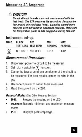
Measuring AC Amperage
CAUTION!Do not attempt to make a current measurement with thetest leads. The 270 measures the current by clamping thejaw around one conductor (wire). Clamping around morethan one wire will result in erroneous readings. Make surethe temperature probe is NOT plugged in during this test.
Instrument set-up:FUNC. BLACK RED MIN MAX
TEST LEAD TEST LEAD READING READING
NOT USED NOT USED 0.01A 400A
Measurement Procedure:1. Disconnect power to circuit to be measured.2. Set rotary switch to function.3. Clamp the jaws around one conductor of the circuit to
be measured. For best results, center the wire in thejaw.
4. Reconnect power to circuit to be measured.5. Read the current on the 270.
Optional Modes (See Other Features Section)
• D-H: Freezes the reading on the LCD.• MAX/MIN: Records minimum and maximum measure-
ments• P-H: Displays peak amperage.
1716
Measuring Resistance
WARNING!Do not attempt to make resistance measurements with circuitenergized. For best results, remove the resistor completely fromcircuit before attempting to measure it. Make sure the tempera-ture probe is NOT plugged in during this test.
NOTE:To make accurate low ohm measurements, short the ends of thetest leads together and press the REL button to store the reading.This will deduct the stored value from subsequent measurementseliminating the test lead resistance from the reading.
Instrument set-up:FUNC. BLACK RED MIN MAX
TEST LEAD TEST LEAD READING READING
W COM V/W 0.1W 40.00MW
Measurement Procedure:1. Disconnect power to circuit to be measured.2. Plug black test lead into the COM input jack.3. Plug red test lead into V/W input jack.4. Set the rotary switch to the W function.5. Connect test leads to circuit to be measured.6. Read the resistance value on the 270.
Optional Modes (See Other Features Section)
• D-H: Freezes the reading on the LCD.

Measuring Diodes
WARNING!Do not attempt to make diode measurements with the circuitenergized. For accurate tests, remove the diode completelyfrom the circuit prior to measuring it. Make sure the tempera-ture probe is NOT plugged in during this test.
Instrument set-up:FUNC. BLACK RED
TEST LEAD TEST LEAD
COM V/W/mA
Measurement Procedure:1. Disconnect power to circuit to be measured.2. Plug black test lead into the COM input jack.3. Plug red test lead into V/W input jack.4. Set the rotary switch to the 5. Connect the black test lead to the banded end of the diode
(cathode) and the red test lead to the non-banded end ofthe diode (anode).
6. For a good diode, the reading on the display should bebetween 0.5V and 0.8V. The reading will be lower for agermanium diode.
7. Reverse the leads on the diode.8. For a good diode, the reading on the display should be OL
(overload).
Optional Modes (See Other Features Section)
• D-H: Freezes the reading on the LCD.
1918
position.
Measuring Continuity
WARNING!Do not attempt to make continuity measurements with circuitenergized. Make sure the temperature probe is NOT pluggedin during this test.
Instrument set-up:FUNC. BLACK RED
TEST LEAD TEST LEAD
COM V/W
Measurement Procedure:1. Disconnect power to circuit to be measured.2. Plug black test lead into the COM input jack.3. Plug red test lead into V/W input jack.4. Set the rotary switch to the position.5. Connect test leads to circuit to be measured.6. The 270 will beep and the LED will illuminate at
resistances of 35W or lower.
Optional Modes (See Other Features Section)
• D-H: Freezes the reading on the LCD.

Measuring Capacitance
WARNING!All capacitance measurements are to be made on de-energizedcircuits with all capacitors discharged only. Failure to de-energizeand discharge capacitors prior to measuring them could result ininstrument damage and/or personal injury. Make sure the temper-ature probe is NOT plugged in during this test.
Instrument set-up:FUNC. BLACK RED
TEST LEAD TEST LEAD
COM V/W/mA
Measurement Procedure:1. Disconnect power to circuit to be measured.2. Plug black test lead into the COM input jack.3. Plug red test lead into V/W input jack.4. Set the rotary switch to the 5. Remove the capacitor from the circuit and discharge it.6. Connect test leads to the capacitor to be measured.
Observe polarity on polarity sensitive capacitors.7. Read the capacitor value on the LCD.
Optional Modes (See Other Features Section)
• D-H: Freezes the reading on the LCD.
2120
Measuring Frequency
WARNING!Never attempt a frequency measurement with a voltage sourcegreater than 500V. Determine the voltage of any unknown fre-quency source before connecting the instrument in frequencymode. Make sure the temperature probe is NOT plugged induring this test.
Instrument set-up:FUNC. BLACK RED
TEST LEAD TEST LEAD
Hz COM V/W/mA
Measurement Procedure:1. Disconnect power to the circuit to be measured.2. Plug black test lead into the COM input jack.3. Plug red test lead into V/W input jack.4. Set the rotary switch to the Hz position.5. Reconnect power to the circuit to be measured.6. Read the frequency on the LCD.
Optional Modes (See Other Features Section)
• D-H: Freezes the reading on the LCD.• MAX/MIN: Records minimum and maximum measure-
ments
position.

Measuring DC Microamps
CAUTION!Do not attempt to make a current measurement with the testleads connected in parallel with the circuit to be tested. Testleads must be connected in series with the circuit. Do notattempt to make a current measurement of circuits with morethan 600V present. Instrument damage and/or personal injurymay result. Make sure the temperature probe is NOT pluggedin during this test.
Instrument set-up:FUNC. BLACK RED MINIMUM MAXIMUM
TEST LEAD TEST LEAD READING READING
COM V/W /mA 0.01mA400.0mA
Measurement Procedure:1. Disconnect power to circuit to be measured.
2. Plug black test lead into the COM input jack.
3. Plug red test lead into the V/WW/mmA input jack.
4. Set the rotary switch to the mmA function.
5. Connect the test leads in series to the circuit to bemeasured.
6. Reconnect power to circuit to be measured.
7. Read the current on the 270.
Optional Modes (See Other Features Section)
• D-H: Freezes the reading on the LCD.• MAX/MIN: Records minimum and maximum measure-
23
Measuring TemperatureCAUTION!Do not attempt to make a temperature measurement with thetest leads connected to the 270. Remove the test leads andinsert the K-type temperature probe.
Instrument set-up:FUNC. BLACK RED MINIMUM MAXIMUM
TEST LEAD TEST LEAD READING READING
400ºF N/A N/A -40.0ºF 399.9ºF1000ºF N/A N/A -40ºF 1000ºFMeasurement Procedure:
1. Remove the test leads from the input jacks.
2. Observing polarity, insert the temperature probeinto the Type K input jack.
3. Set the rotary switch to the appropriate functionfor the temperature being measured.
4. Touch the temperature probe to the item to bemeasured.
5 . Read the temperature on the LCD.
Note:The 270 will beep when no probe is connected tothe temperature input.
Optional Modes (See Other Features Section)
• D-H: Freezes the reading on the LCD.• MAX/MIN: Records minimum and maximum measure
ments.• REL: Enables temperature differential tests to be per
formed. See Application Notes section.
22

2524
Other Features (continued)
Relative mode (REL)
The Relative mode (REL) takes the reading on the dis-play at the time the REL button is pressed and uses it asa reference value that is deducted from all subsequentmeasurements. This can be very helpful in deducting theresistance of test leads in low ohm measurements.
1. To use Relative mode manually select the rangefor the function.
2. Depress the REL button to store the reading on thedisplay. The “REL” indicator will illuminate con-firming the 270 is in relative mode.
3. Now when making a measurement the valuestored will be deducted from the actual reading.
4. To see what the stored value is, depress the RELbutton again and the “REL” indicator will flash andthe reading on the display will show the storedvalue. Depress the REL button again to return toREL mode.
5. To clear or exit relative mode, press and hold theREL button for approximately two seconds and the270 will beep and return to normal operation.
Note: Differential temperature measurements can bemade using relative mode. See the application noteon page 33 for more information.
E. Other Features
Non-Contact Voltage (NCV)
WARNING!Never rely on the non-contact voltage function only. If a volt-age is not detected, confirm there is no voltage by performinga voltage measurement with the test leads. Failure to do thiscould result in injury. The non-contact voltage feature worksbest when testing single wires. Make sure the test leads andtemperature probe are disconnected while using the NCV fea-ture.
Instrument set-up:FUNC. BLACK RED
TEST LEAD TEST LEAD
NCV N/A N/A
Measurement Procedure:Remove the test leads and temperature probe prior to using theNCV feature.
1. Turn the meter on to any range.2. Press and hold the NCV button.3. Put the arrow marked on the jaw close to the wire under
test.4. If voltage is present the 270 will beep and the NCV LED
will illuminate.5. If voltage is not detected, confirm the result by perform-
ing a voltage measurement as outlined earlier in thismanual.

2726
Other Features (continued)
Peak Hold Mode (P-H)
The Peak hold function allows the 270 to display the themaximum and minimum peak voltage or current. This ishelpful when measuring inrush current.
NOTE: Peak mode can display up to 70 counts on the dis-play when first activated. For example, if the 270 is set tothe ACA function and manually ranged to the 40A range,when P-H is activated the display can read up to 0.70.This is normal for this function.
1. Manually select the range for the function and setthe meter up to perform a measurement as outlinedearlier in this manual.
2. Depress and hold the P-H button until CAL is dis-played. Once CAL clears from the display you maymake a measurement. Press P-H repeatedly to cyclethrough the maximum and minimum peak readings.Press and hold the P-H button for two seconds toreturn to normal operation.
For inrush current, after CAL clears press the P-Hbutton and then supply power to the device undertest. The 270 will capture the maximum and mini-mum peak inrush.
Other Features (continued)
Record Mode (MAX / MIN)
Record mode allows you to record the maximum andminimum readings measured during a test.
1. Manually select the range for the function and setthe meter up to perform a measurement as outlinedearlier in this manual.
2. Depress the MAX/MIN button and “MAX” will bedisplayed along with the maximum reading record-ed. Press the MAX/MIN button again and the displaywill show MIN and the minimum reading recorded.
3. Press the MAX/MIN button again and MAX MIN willblink and the 270 will display the measured value inreal time. Steps 2 and 3 can be repeated to read themaximum and minimum recorded values.
If REL was activated and is being used withMAX/MIN, REL and MAX MIN will blink and the dis-play will show the REL value instead of the real timereading.
5. To exit record mode, press and hold the MAX/MINbutton for approximately two seconds and the 270will beep and return to normal operation.

2928
F. Application Notes (AC Volts)
Disconnect power from theterminal block, find the fuseor circuit breaker that con-trols the block and turn itoff.
Set up the meter followingthe steps under“Measurement Procedure”
on page 15. Then proceed withthe following:
•Connect the red test lead tothe hot side of the block andthe black lead to the neutralside of the block. Reconnectpower to the block and read
the voltage on the meter. Thereading should be approximately 110V to130V.
• Disconnect power from the block and movethe red wire to ground. Reconnect power tothe block and read the voltage on the meter.Typically less than 20V should exist fromneutral to ground. If 110V or above exists,the block may be wired incorrectly.
Other Features (continued)
Manual Ranging (R-H)
The range hold button (R-H) activates manual ranging. Press the R-H button to cycle through available ranges.Pressing and holding the R-H button for approximately twoseconds returns the meter to autorange mode and “auto” willbe displayed in the upper left corner of the display.
Data Hold (D-H)
Press the D-H button at any time to freeze the reading on the LCD display. This function is useful when measuring in locations where the display is difficult to read.
LED Indicators
The 270 is equipped with three LED indicators at the top nearthe jaw.
HI-V This indicator flashes and the 270 beeps when the test leads are in contact with a
voltage of 30V AC/DC or more.
NCV This indicator illuminates when the non-contact voltage detector senses a voltage.
This is the visual indicator of continuity. ThisLED also flashes anytime the buzzer beeps.

3130
31
When measuring resistance of a motor, makesure the power is disconnected prior to testing.Set up meter following steps under“Measurement Procedure” on page 16, andproceed with the following:
• Connect the red test lead to one powerinput line of the motor and the black testlead to the other power input line of themotor. In most applications if the readingis OFL, the motor winding is open.
• Connect the red test lead to the frame ofthe motor and the black test lead to thewinding. In most applications if a readingof 0 Ohms is displayed, the winding isshorted to the motor frame (ground).
Application Notes (DC Volts)The 270 will accurately measure rectified DC Voltages likethose encountered in furnaces and other appliances eventhough many of these devices do not have output filteringor other signal conditioning.
When measuring DC Voltage of a bat-tery, the most accurate reading can beattained by testing the battery underload. To accomplish this, follow steps1 through 4 shown on page 14 andthe following (with the battery inholder and device turned on):• Connect the red test lead from the
meter to the positive (+) terminalof the battery.
• Connect the black test lead to thenegative (-) terminal of the battery.
Application Notes (Resistance)

3332
Application Notes (Temperature Differential)
When measuring temperature there may be applica-tions when knowing the differential between two mea-surements is required. This can be accompished byfollowing these steps.• Remove the test leads from the input jacks. Insert
the K-type thermocouple probe into the input jackon the 270. Set the 270 to the desired TEMPfunction.
• Touch the temperature probe sensor to the deviceunder test (T1).
• When the reading stabilizes, press the REL but-ton. The display will read “0” and T1 will bestored as the reference value that the next mea-surement will be made relative to.
• Touch the temperature probe sensor to the deviceunder test (T2).
• The 270 will display the differential temperatureT2-T1.
Application Notes (AC Amps)
When measuring AC Amps of a motor thereare two types of measurements that can bemade, running current and in-rush or start-upcurrent. Start-up current will usually be muchhigher than running current.Set up the meter following the steps under“Measurement Procedure” on page 17, andthen proceed with the following:
• Clamp the meter around a single wireand reconnect power to the device. Readthe current displayed on the meter. Thisis the running current of the motor.
• Disconnect power to the motor and putthe meter in PEAK HOLD mode.Reconnect the power and readthe current displayed on themeter. This is the in-rush orstart-up currentof the motor.

3534
H. Maintenance
1. Battery / Fuse Replacement: The 270 will display a bat-tery symbol when the internal 9 Volt battery needsreplacement. If DC microamps does not operate correct-ly the 0.5A / 600V fuse needs to be replaced. The batteryor fuse is replaced as follows:
a. Disconnect and remove all test leads from live circuits and from the 270.
b. Loosen the screw from the back of the 270 battery /fuse cover.
c. Remove the battery / fuse compartment cover.d. Remove old battery or fuse and replace with new
battery or fuse. Observe the correct polarity on thebattery. Only install the correct value fuse(0.5A/600V). Failure to do so can result in instru-ment damage.
e. Reassemble the instrument in reverse order from above.
2. Cleaning your 270: Use a mild detergent and slightly damp cloth to clean thesurfaces of the 270.
G. Trouble Shooting Problem Probable Causes
Does not power up • Dead or defective battery• Broken wire from battery
snap to PCB
Won’t display DC • Open fusemicroamp readings • Open test lead
• Improperly connected to circuit under test
All functions except • Very weak battery that will ohms read high not turn on the low battery
indicator on the LCD
AC Volts do not read • Very weak battery that will not turn on the low battery indicator on the LCD
Non-Contact Voltage • The non-contact voltage featuredoes not work works best when used to test a
single wire. Make sure the arrowon the jaw is pointed at the wire.
The meter beeps when • This is a reminder to remove theset on TEMP test leads and insert the temper-
ature probe. If a probe is insert-ed, this is an indication the probeis open.
AC Amps does not read • Make sure the jaw is clamped around a single wire and the device connected to the wire is turned on.

3736
Accessories
Standard Accessories Part Number9 Volt Alkaline Battery A009ATest Lead Set (1000V CATIII 10A) A0850.5A / 600V Fuse A107Soft Carrying Pouch A270
Optional Accessories Part NumberFused Test Lead Kit FTLK3Deluxe Test Lead Set TLS2000RBCarbon Monoxide Adapter A771Pressure Adapter A620

3736
Accessories
Standard Accessories Part Number9 Volt Alkaline Battery A009ATest Lead Set (1000V CATIII 10A) A0850.5A / 600V Fuse A107Soft Carrying Pouch A270
Optional Accessories Part NumberFused Test Lead Kit FTLK3Deluxe Test Lead Set TLS2000RBCarbon Monoxide Adapter A771Pressure Adapter A620

3938

3938

Func. Range Res.DCV 400mV 0.1mV
4V 0.001V40V 0.01V400V 0.1V600V 1V
ACV 400mV 0.1mV4V 0.001V40V 0.01V400V 0.1V750V 1V
ACA 40A 0.1A400A 1A
OHM 400W 0.1W4kW 0.001kW40kW 0.01kW400kW 0.1kW4MW 0.001MW40MW 0.01MW
DCuA 40uA 0.01uA400uA 0.1uA
TEMP -40ºF to 1000ºF 0.1ºF / 1ºF
270 SPECIFICATIONS (PARTIAL LIST)
±0.5% Basic DCV Accuracy (also see pages 8-11)
Test Products International, Inc.9615 SW Allen Blvd., Ste. 104Beaverton, OR USA 97005503-520-9197 • Fax: [email protected] • 1/25/05 copyright © 2005 Test Products International, Inc.