digital circuits – dr. n. aydin - yıldız technical...
TRANSCRIPT

1
DIGITAL CIRCUITS – EXAMPLES (questions and solutions) Dr. N. AYDIN [email protected] _____________________________________________________________________ Example 1. Assume that the inverter in the network below has a propagation delay of 5 ns and the
AND gate has a propagation delay of 10 ns. Draw a timing diagram for the network showing X, Y, and Z. Assume that X is initially 0, Y is initially 1, X becomes 1 for 80 ns, and then X is 0 again.
………………………………………………………………………………………….. Solution 1. You must remember to take into account delays. Steps for the solution:
1. Draw an empty timing diagram 2. Write related characteristic equation: Z = XY = XZ' 3. Plot initial states for X and Y 4. Plot remaining diagram by considering appropriate delays
_____________________________________________________________________
0 10 20 30 40 50 60 70 80 90 100 t(ns)
X
Y
Z
0 10 20 30 40 50 60 70 80 90 100 t(ns)
X
Y
Z
Y
X
Z

2
Example 2. A flip-flop can be constructed from two NAND gates connected as follows:
(a) What restriction must be placed on S and R so that P always equal Q' ? (b) Construct a next-state table and derive the characteristic (next-state) equation
for the flip-flop. (c) Complete the following timing diagram for the flip-flop.
………………………………………………………………………………………….. Solution 2.
(a) The inputs which must be restricted for this circuit can be determined by construction of a simple state table. From the table, Q=P=1 for S=R=0. Also by inspection, if S=R=0, regardless of any feedback Q=P=1. So for a proper flip-flop operation S=R=0 must not be allowed to occur for this circuit.
Q = S'+P' P = R'+Q'
S R Q P 0 0 1 1
0 1 1 0 1 0 0 1 1 1 no change no change
S
R
Q P
S
R
Q
P = Q'

3
Alternatively, a full truth table can be constructed to see behaviour of the network. Input-output equations are:
Q = S'+P' P = R'+Q'
Inputs Present state Next state 1 Next state 2 Next state 3 Explanation S R Q P Q+ P+ Q++ P++ Q+++ P+++ 0 0 0 0 1 1 1 1 1 1 Stable 0 0 0 1 1 1 1 1 1 1 Stable 0 0 1 0 1 1 1 1 1 1 Stable 0 0 1 1 1 1 1 1 1 1 Stable 0 1 0 0 1 1 1 0 1 0 Stable 0 1 0 1 1 1 1 0 1 0 Stable 0 1 1 0 1 0 1 0 1 0 Stable 0 1 1 1 1 0 1 0 1 0 Stable 1 0 0 0 1 1 0 1 0 1 Stable 1 0 0 1 0 1 0 1 0 1 Stable 1 0 1 0 1 1 0 1 0 1 Stable 1 0 1 1 0 1 0 1 0 1 Stable 1 1 0 0 1 1 0 0 1 1 Oscillates 1 1 0 1 0 1 0 1 0 1 Stable 1 1 1 0 1 0 1 0 1 0 Stable 1 1 1 1 0 0 1 1 0 0 Oscillates
If we do not allow the R=S=0 state, then the flip flop cannot get into the Q=Q’ state.
(b) The first step is to form a next-state table. This is basically a reduced version of the full truth table given in (a). The states (0 and 1), which are not allowed for this particular flip-flop, are treated as don’t cares. The resultant function can then be minimised using Karnaugh map. Restricted case is treated as don’t care.
S R Q Q+ 0 0 0 0 x 1 0 0 1 x 2 0 1 0 1 3 0 1 1 1 4 1 0 0 0 5 1 0 1 0 6 1 1 0 0 7 1 1 1 1
Q+ = S' + RQ
RQ S
00 01 11 10
0 x x 1 1
1 0 0 1 0

4
(c) A δt time delay should be considered when constructing timing diagram. Although it is not required, drawing S', P', R', and Q' is helpful.
Q = S’+P’ P = R’+Q’
Q+ = S’ + RQ
S
R
Q P
S'
R'
Q' P'
δt

5
Example 3. Design a 3 bit counter which counts in the sequence: 001, 011, 010, 110, 111, 101, 001, …
(a) Use clocked D flip-flops (b) Use clocked T flip-flop (c) Use J-K flip-flop
Reminder: The following table summarizes state changes for D, T, and J-K flip-flops
Q → Q+
D flip-flop D
Toggle Flip-flop T
J-K Flip-flop J K J K
0 → 0 0 0 0 1 0 0
0 x
0 → 1 1 1 1 0 1 1
1 x
1 → 0 0 1 0 1 1 1
x 1
1 → 1 1 0 0 0 1 0
x 0
………………………………………………………………………………………….. Solution 3.
Step1. Determine the number of flip-flop stages required. In this case it is 3. Step2. Flip-flop outputs Q2Q1Q0 are determined by the specifications. Present state and next state tables are constructed. The present state-next state table (quick and full) is shown below. Make sure that the counter counts in the following order:
001→011→010→110→111→101 Quick table: Full table:
Present-state Next-state Q2 Q1 Q0 Q2+ Q1+ Q0+ 0 0 1 0 1 1 0 1 1 0 1 0 0 1 0 1 1 0
1 1 0 1 1 1 1 1 1 1 0 1 1 0 1 0 0 1
On Karnaugh map, put x for the states that does not exist in this table
Step 3. Find state transition relationships for each pair of present-state-next-state columns, using the state change table for the chosen flip-flop. Step 4. Use the complete present state as input to truth tables whose outputs are state transition values corresponding to each flip-flop input. Step 5. With map or Boolean algebra methods find expressions (excitation equations) for each flip-flop input from the truth tables of step 4. Step 6. Form system outputs from combinations of the flip-flop outputs. Step 7. Realize the excitation expressions as combinational logic drives for the flip-flop inputs. Step 8. You can check your design by constructing a timing diagram.
Present-state Next-state Q2 Q1 Q0 Q2+ Q1+ Q0+ 0 0 0 x x x 0 0 1 0 1 1 0 1 0 1 1 0 0 1 1 0 1 0 1 0 0 x x x 1 0 1 0 0 1
1 1 0 1 1 1
1 1 1 1 0 1

6
(a) Implementation using D flip-flop. (Since the quick table is used, do not forget to put x to the respective boxes in the Karnaugh map for missing states in the table)
Present-state Next-state Flip-flop input Q2 Q1 Q0 Q2+ Q1+ Q0+ D2 D1 D0 0 0 0 1 1 1
0 1 1 1 1 0
1 1 0 0 1 1
0 0 1 1 1 0
1 1 1 1 0 0
1 0 0 1 1 1
0 0 1 1 1 0
1 1 1 1 0 0
1 0 0 1 1 1
Construct related Karnaugh maps. Note that ‘flip-flop input’ columns are the same as the ‘next-state’ columns for D flip-flops. Therefore for the D flip-flop, input equations can be found directly from the next state table. D2 D1 D0
Q1Q0 Q2
00 01 11 10 00 01 11 10 00 01 11 10
0 x 0 0 1 x 1 1 1 x 1 0 0
1 x 0 1 1 x 0 0 1 x 1 1 1
D2 = Q0' + Q2Q1 D1 = Q2' + Q0' D0 = Q1' + Q2
(b) Implementation using T flip-flop. The following table gives the states of the flip-flop inputs. (use the reminder if you don’t remember the state changes).
Present-state Next-state Flip-flop input Q2 Q1 Q0 Q2+ Q1+ Q0+ T2 T1 T0 0 0 0 1 1 1
0 1 1 1 1 0
1 1 0 0 1 1
0 0 1 1 1 0
1 1 1 1 0 0
1 0 0 1 1 1
0 0 1 0 0 1
1 0 0 0 1 0
0 1 0 1 0 0
D2 Q2
Q2'
D1 Q1
Q1'
D0 Q0
Q0'
Clock

7
T2 T1 T0
Q1Q0 Q2
00 01 11 10 00 01 11 10 00 01 11 10
0 x 0 0 1 x 1 0 0 x 0 1 0
1 x 1 0 0 x 0 1 0 x 0 0 1
T2= Q2'Q0'+Q2Q1' T1= Q2'Q1'+ Q2Q1Q0 T0= Q2Q0'+ Q2'Q1Q0
(c) Implementation using J-K flip-flop. The following table gives the states of the flip-flop inputs.
Present-state Next-state Flip-flop inputs Q2 Q1 Q0 Q2+ Q1+ Q0+ J2 K2 J1 K1 J0 K0 0 0 0 1 1 1
0 1 1 1 1 0
1 1 0 0 1 1
0 0 1 1 1 0
1 1 1 1 0 0
1 0 0 1 1 1
0 0 1 x x x
x x x 0 0 1
1 x x x x 0
x 0 0 0 1 x
x x 0 1 x x
0 1 x x 0 0
J2 J1 J0
Q1Q0 Q2
00 01 11 10 00 01 11 10 00 01 11 10
0 x 0 0 1 x 1 x x x x x 0
1 x x x x x 0 x x x x x 1
K2 K1 K0
Q1Q0 Q2
00 01 11 10 00 01 11 10 00 01 11 10
0 x x x x x x 0 0 x 0 1 x
1 x 1 0 0 x x 1 0 x 0 0 x
T2 Q2
Q2'
T1 Q1
Q1'
T0 Q0
Q0'
Clock

8
From the Karnaugh maps, and also by inspection: J2 = Q0' , K2 = Q1' ; J1 = Q2' , K1 = Q2Q0 ; J0 = Q2 , K0 = Q1Q2'
You can verify operation of the circuits by constructing timing diagram. _____________________________________________________________________
J2 Q2
Q2'
J1 Q1
Q1'
J0 Q0
Q0'
Clock
K2 K1 K0

9
Example 4. An engine needs to go through four strokes, all of equal duration (see figure for state sequence). On the first stroke the inlet valve is open and the outlet is closed; on the second stroke the inlet is closed; on the third stroke a spark is delivered; and the forth stroke the outlet is open for the exhaust from the explosion to vent. Then the first stroke comes again and the cycle repeats. Design a controller for the system, with a clock for input and with three outputs: one to open the inlet, one to open the outlet, and one to ignite the spark. Assume that if the control to open a valve isn’t asserted, the valve closes (spring-loaded valve). The frequency of the clock will determine the speed of engine.
………………………………………………………………………………………….. Solution 4. Step 1. Each of the four strokes is a different state. Since two flip-flop outputs can represent four states, two flip-flops are required to design a controller. Step 2. Naturally, a positional binary code can be used to assign flip flop outputs (state variables) to the states:
B A S1 0 0 S2 0 1 S3 1 0 S4 1 1
Such coding could work properly. However, we observe that the system has three outputs, and the proper functioning of the engine requires that outputs be asserted only during their intended states. We see that in the sequence 00 01 10 11, two flip-flop outputs try to change at once between second and third states and between last and first states. Because of unequal propagation delays in flip-flops, it is possible that two flip-flops will not change simultaneously and that a glitch will occur and will cause the system to function unexpectedly before it gets to the expected next state. Instead of positional binary code, two-bit Gray code can be used. In Gray code, numbers change only one bit at a time. Rearranged (according to the Gray code) state table for the system is:
B A INLET OUTLET SPARK S1 0 0 1 0 0 S2 0 1 0 0 0 S3 1 1 0 0 1 S4 1 0 0 1 0
Step 3. Form a present-state next-state table and determine input conditions for the flip-flops (we use J-K flip flop in this design).
Ignite spark
Open outlet
State sequence of engine cycle for example 4
Close outlet Open inlet
Close inlet

10
Present-state Next-state Flip-flop inputs B A B+ A+ JB KB JA KA 0 0 1 1
0 1 1 0
0 1 1 0
1 1 0 0
0 1 x x
x x 0 1
1 x x 0
x 0 1 x
Step 4. Determine flip-flop inputs equations by constructing related Karnaugh maps or by inspection of the table constructed in step 3.
JB KB JA KA A B
0 1 0 1 0 1 0 1
0 0 1 x x 1 x x 0
1 x x 1 0 0 x x 1
JB = A , KB = A' ; JA = B' , KA = B
Step 5. The output combinational logic can be determined from the second table (rearranged for Gray code) given in step 2. INLET = B'A' ; OUTLET = BA' ; SPARK = BA Step 6. Draw the circuit diagram Step 7. As an extra exercise, you can repeat the design by using other flip-flop types (D, T, and S-R). You can also verify the circuit by constructing the timing diagram. _____________________________________________________________________
JA A
A'
JB B
B' KA KB
SPARK
INLET
OUTLET
Clock

11
S0 z=0
S1 z=0
S3 z=1
S2 z=0
y=1
y=1
y=0
y=0
y=1
y=1
y=0
y=0
(input: y, output: z)
Example 5. We wish to design a sequence detector circuit, which detects three or more consecutive 1’s in a string of bits coming through an input line.
(a) Find the state diagram. (b) Determine the type of the circuit (Moore or Mealy model). (c) Tabulate state (or transition) table of sequence detector. (d) Implement the circuit using D and J-K flip-flops.
………………………………………………………………………………………...... Solution 5.
(a) Starting with state S0, if incoming data is 0 the circuit stays in the same state. If input is 1 then the state goes to S1 indicating that a 1 is detected. If next input is again 1 then the state goes to S2. But if the input is 0 then the state goes back to S0. The third consecutive 1 sends the circuit to S3 producing an output, which indicates three consecutive 1’s were detected. The circuit stays at S3 as long as there are three or more consecutive 1’s received.
(b) This is a Moore model sequential
circuit since the output is 1 when the circuit is in state S3 and 0 otherwise (the output z is a function of present state only).
(c) The state table can be derived from the state diagram of (a).
Present state Input Next state Output B A y B+ A+ z
S0 S0 S1 S1 S2 S2 S3 S3
0 0 0 0 1 1 1 1
0 0 1 1 0 0 1 1
0 1 0 1 0 1 0 1
S0 S1 S0 S2 S0 S3 S0 S3
0 0 0 1 0 1 0 1
0 1 0 0 0 1 0 1
0 0 0 0 0 0 1 1
(d) D flip-flop implementation can be realized directly from the state table of (c)
DB DA z
DB = Ay+By DA = A'y+By z = AB
Ay B
00 01 11 10 00 01 11 10 00 01 11 10
0 0 0 1 0 0 1 0 0 0 0 0 0
1 0 1 1 0 0 1 1 0 0 0 1 1
12
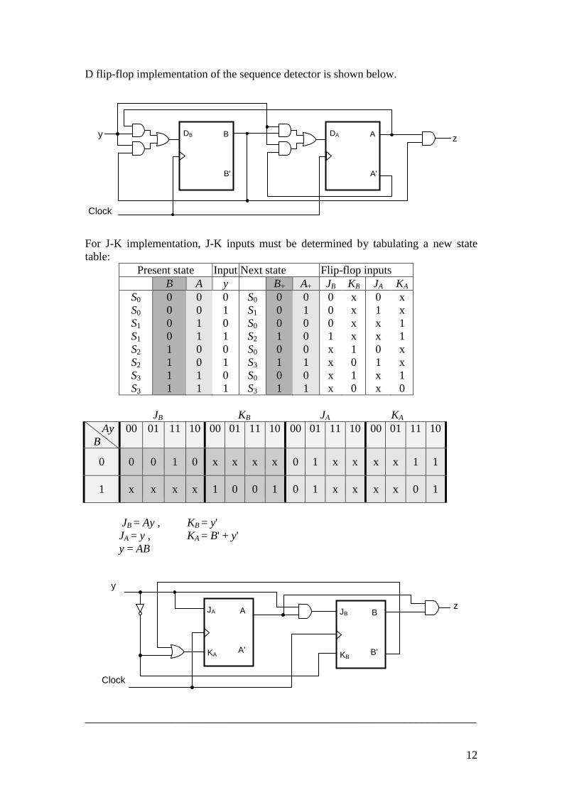
D flip-flop implementation of the sequence detector is shown below. For J-K implementation, J-K inputs must be determined by tabulating a new state table:
Present state Input Next state Flip-flop inputs B A y B+ A+ JB KB JA KA
S0 S0 S1 S1 S2 S2 S3 S3
0 0 0 0 1 1 1 1
0 0 1 1 0 0 1 1
0 1 0 1 0 1 0 1
S0 S1 S0 S2 S0 S3 S0 S3
0 0 0 1 0 1 0 1
0 1 0 0 0 1 0 1
0 0 0 1 x x x x
x x x x 1 0 1 0
0 1 x x 0 1 x x
x x 1 1 x x 1 0
JB KB JA KA
Ay B
00 01 11 10 00 01 11 10 00 01 11 10 00 01 11 10
0 0 0 1 0 x x x x 0 1 x x x x 1 1
1 x x x x 1 0 0 1 0 1 x x x x 0 1
JB = Ay , KB = y' JA = y , KA = B' + y' y = AB
_____________________________________________________________________
DB B
B'
Clock
DA A
A'
y z
JA A
A' KA
JB B
B' KB
Clock
y
z

13
Example 6. We wish to design a digital system with two flip-flops, say B and C, and one 4 bit binary counter A, in which the individual flip-flops are denoted by A4, A3, A2, A1. A start signal S initiates the system operation by clearing the counter A and flip-flop C, and setting flip-flop B to one. The counter is then incremented by one starting from the next clock pulse and continues to increment until the operations stop. Counter bits A3 and A4 determine the sequence of operations:
If A3 = 0, B is cleared to 0 and the count continues. If A3 = 1, B is set to 1; then if A4 = 0, the count continues, but if A4 = 1, C is set to 1on the next clock pulse and the system stops counting. Then if S = 0, the system remains in the initial state, but if S = 1, the operation cycle repeats. (a) Draw the ASM chart. (b) Tabulate the timing sequence.
………………………………………………………………………………………...... Solution 6.
Initial state
S
A ← A+1
A ← 0 B ← 1, C ← 0
A3
B ← 0
B ← 1
A4
C ← 1
0
1
0 1
0
1
T0
T1
T2

14
(a) ASM chart is shown above. When no operations are performed, the system is in the initial state T0, waiting for the start signal S. When input S is equal to 1, counter A and flip-flop C are cleared to 0, flip-flop B is set to 1, and controller goes to state T1. When the control is in state T2, flip-flop C is set to 1 and the circuit goes back to the initial state, T0. The ASM chart consists of three states and three blocks. The block associated with T0 consists of the state box, one decision box, and one conditional box. The block associated with T2 consists of only the state box. The control logic has one external input, S, and two status inputs, A3 and A4.
(b) Every block in an ASM chart specifies the operations that are to be performed
during one common clock pulse. The operations specified within the state and conditional boxes in the block are performed in the data-processor subsection. The change from one state to the next is performed in the control logic. The following table shows the binary values of the counter and the two flip-flops after every clock pulse. The table shows separately the status of A3 and A4 as well as the present state of the controller. We start with state T1 right after the input signal S has caused the counter A and flip-flop C to be cleared and B set. The system stays in state T1 during the next thirteen clock pulses. Each pulse increments the counter and either clears or sets B. Note the relationship between the time at which A3 becomes 1 and the time at which B is set to 1. When A=0011, the next clock pulse increments the counter to 0100, but that same clock pulse sees the value of A3 as 0, so B is cleared. The next pulse changes the counter from 0100 to 0101, and now A3 is initially equal to 1, so B is set to 1. Similarly, B is cleared to 0 when the count goes from 1000 to 1001, which is A3 is 0 in the present value of the counter. When the count reaches 1100, both A3 and A4 are 1. The next clock pulse increments A by 1, sets B to 1, and transfers control to state T2. Control stays in T2 for only one clock period. The pulse transition associated with T2 sets flip-flop C to 1 and transfers to state T0. The system stays in the initial state T0 as long as S remains 0.
Counter
A4 A3 A2 A1 Flip-flops
B C
Conditions
State 0 0 0 0 0 0 0 1 0 0 1 0 0 0 1 1
1 0 0 0 0 0 0 0
A4 = 0, A3 = 0 T1
0 1 0 0 0 1 0 1 0 1 1 0 0 1 1 1
0 0 1 0 1 0 1 0
A4 = 0, A3 = 1 T1
1 0 0 0 1 0 0 1 1 0 1 0 1 0 1 1
1 0 0 0 0 0 0 0
A4 = 1, A3 = 0 T1
1 1 0 0 0 0 A4 = 1, A3 = 1 T1 1 1 0 1 1 0 T2 1 1 0 1 1 1 T0
_____________________________________________________________________

15
Example 7. The state diagram of a sequential circuit is given as below.
(a) Tabulate the related state table.
(b) Reduce the state table to a minimum number of states using row matching.
(c) Repeat (b) using an implication table.
(d) Draw the reduced state diagram.
………………………………………………………………………………………… Solution 7.
(a) It is more convenient to apply procedures for state reduction using a state table rather than a state diagram. The state table for the given state diagram is tabulated in the following table.
Present state
Next state x = 0 x = 1
Output x = 0 x = 1
a b c d e f g
a b c d a d e f a f g f a f
0 0 0 0 0 0 0 1 0 1 0 1 0 1
(b) Two states are said to be equivalent if, for each member of the set of inputs,
they give exactly the same output and send the circuit either to the same state or to an equivalent state. When two states are equivalent, one of them can be removed without altering the input-output relationships. Step 1. By inspecting the rows in the table of (a), it is possible to see that states g and e are equivalent. They both go to states a and f and have outputs of 0 and 1 for x = 0 and x = 1, respectively. Therefore, states g and e are equivalent and one of these states can be removed. Step 2. The row with present state g is removed and state g in the next state column is replaced by its equivalent, state e. The procedure is shown in the next table.
a
1/0
1/0
0/0
0/0
1/1
1/1
0/0
0/0 b
d
f
c
e g
1/0
1/1 1/1
0/0
0/0
0/0

16
Present state
Next state x = 0 x = 1
Output x = 0 x = 1
a b c d e f
a b c d a d e f a f e f
0 0 0 0 0 0 0 1 0 1 0 1
Step 3. Present state f now has next states e and f and outputs 0 and 1 for x = 0 and x = 1, respectively. Inspection of the rows reveals that states d and f are equivalent. So, state f can be removed and replaced by d. The final reduced state table is shown in the next table.
Present state
Next state x = 0 x = 1
Output x = 0 x = 1
a b c d e
a b c d a d e d a d
0 0 0 0 0 0 0 1 0 1
(c) Checking each pair of states for possible equivalency can be done
systematically by means of an implication table. In this table, on the left side along the vertical are listed all the states except the first, and across the bottom horizontally are listed all the states except the last. The result is a display of all possible combinations of two states with a square placed in the intersection of a row and column where the two states can be tested for equivalence. Step 1. Two states that are not equivalent are marked with a cross in the corresponding square.
b
c
d
e
f
g
a b c d e f
Step 2. We enter in the remaining squares the pairs of states that are implied by the pair of states representing squares. Some of the squares have entries of

17
implied states that must be further investigated to determine whether they are equivalent or not. Therefore, the next step is to make successive passes through the table to determine whether any additional squares should be marked with a cross. A square in the table is crossed out if it contains at least one implied pair that is not equivalent.
b a-c b-d
c a-a b-d
a-c d-d
d
e a-e f-f
f e-g f-f
a-g f-f
g a-f f-f
a-a f-f
a-g f-f
a b c d e f
Step 3. There is no need to include self implied pairs (a-a and f-f) in the table. The final implication table is shown below.
b a-c b-d
c a-a b-d
a-c d-d
d
e a-e f-f
f e-g
a-g f-f
g a-f f-f
a-g f-f
a b c d e f
From the table, we can conclude that the equivalent states are (d, f) and (e, g) (cross sections of shaded squares). So d ≡ f and e ≡ g. The reduced state table is obtained by replacing f by d and g by e. The result is the same as obtained in (a) for this example. However, the implication table provides much more reduction than the row matching in many cases.

18
Present state
Next state x = 0 x = 1
Output x = 0 x = 1
a b c d e
a b c d a d e d a d
0 0 0 0 0 0 0 1 0 1
(d) The reduced state diagram is illustrated below.
_____________________________________________________________________
a
1/0
1/0
0/0
1/1
0/0
0/0 b
d
c e
1/0 1/1
0/0
0/0

19
Example 8. The internal connection diagram for a PLA is given below.
(a) Write the equations realized by the PLA. (b) Specify the truth table for a ROM which would realize the same function
………………………………………………………………………………………...... Solution 8.
(a) X = A'BD + C'D + AB' + AB'C'D' Y = A'BD + BCD + AB' Z = A'BD + BCD + ABC + AB'C'D'
(b) ROM table is given below. Realization by ROM does not require any minimization. All states are simply mapped as defined in the state table. Size of the ROM would be 16x4 bits as shown in the block diagram below.
_____________________________________________________________________
A B C D X Y Z 0 0 0 0 0 0 0 0 1 1 1 1 1 1 1 1
0 0 0 0 1 1 1 1 0 0 0 0 1 1 1 1
0 0 1 1 0 0 1 1 0 0 1 1 0 0 1 1
0 1 0 1 0 1 0 1 0 1 0 1 0 1 0 1
0 1 0 0 0 1 0 1 1 1 1 1 0 1 0 0
0 0 0 0 0 1 0 1 1 1 1 1 0 0 0 1
0 0 0 0 0 1 0 1 1 0 0 0 0 1 1 1
A B C D
X Z Y
16x4 ROM
A B C D
X Y Z

20
Example 9. Realize the following state table using
(a) a clocked J-K flip-flop (use short-cut method) (b) a clocked D flip-flop (use PLA to implement input equation)
Input (WXY = ) Output 000 001 010 011 100 101 110 111 Z =
a a a b b b b a a 0 b a b b a a b b a 1
………………………………………………………………………………………….. Solution 9. Reminder: Short-cut method does not require deriving a separate state table for J-K inputs. J-K inputs can be mapped directly from the next state table. Assuming we have four variables (ABCD), flip-flop input equations can be derived directly from the Karnaugh map constructed using next state table. J input can be obtained by grouping 1s; K input can be obtained by either grouping 0s, or grouping 1s and then taking complement of the resultant equation. The table at right hand side can be used as guide. The following tables are to clarify the procedure.
JC KC'
CD AB 00 01 11 10
JA 00
0 1 3 2 00 JB
01 4 5 7 6
01 KB'
KA' 11
12 13 15 14 11
10 8 9 11 10
10 JB
00 01 11 10
JD KD' JD
CD B
00 01 11 10
JA 0
0 1 3 2
1 4 5 7 6
CD B
00 01 11 10
KA' 1
12 13 15 14
0 8 9 11 10
CD A
00 01 11 10
JB 0
0 1 3 2
1 8 9 11 10
CD A
00 01 11 10
KB' 1
4 5 7 6
0 12 13 15 14
KC'
D AB 1 0
00 3 2
01 7 6
11 15 14
10 11 10
JD
C AB 0 1
00 0 2
01 4 6
11 12 14
10 8 10
JC
D AB 0 1
00 0 1
01 4 5
11 12 13
10 8 9
KD'
C AB 1 0
00 1 3
01 5 7
11 13 15
10 9 11

21
(a) First, tabulate a state transition table. We have tree inputs (WXY) and one output (Z). We need only one flip-flop (Q) for this circuit (log22 = 1). Then we will derive J-K flip-flop input map using short-cut method.
Present
state
Input Next state
Out
Q W X Y Q+ Z a a a a a a a a b b b b b b b b
0 0 0 0 0 0 0 0 1 1 1 1 1 1 1 1
0 0 0 0 1 1 1 1 0 0 0 0 1 1 1 1
0 0 1 1 0 0 1 1 0 0 1 1 0 0 1 1
0 1 0 1 0 1 0 1 0 1 0 1 0 1 0 1
a a b b b b a a a b b a a b b a
0 0 1 1 1 1 0 0 0 1 1 0 0 1 1 0
0 0 0 0 0 0 0 0 1 1 1 1 1 1 1 1
From the map and by inspection;
JQ = W'X + WX' = W ⊕ X , by grouping 1s within upper two rows KQ = X'Y' + XY = (X ⊕ Y)' , by grouping 0s within lower two rows Z = Q , by inspecting the state table
Note that KQ can also be derived by first finding KQ' and then complementing the result. To do this, first 1s are grouped within lower two rows, and then the minimized equation for KQ' is derived. The final step is to complement the KQ', which gives KQ.
KQ = (KQ')' = (X'Y + XY')' = (X + Y') (X' + Y) = X'Y' + XY = (X ⊕ Y)' The circuit implementation is given below.
XY QW
00
01
11
10
JQ 00 0 0 1 1
01 1 1 0 0
KQ' 11 0 1 0 1
10 0 1 0 1
J Q
Q' K
W
X
Clock
X
Y
Z

22
(b) For D flip-flop implementation, the same table and Karnaugh map is in (a) used. The next state table is directly used to derive input equation for D flip-flop. We obtain the following input equation by grouping the shaded ones on the map.
DQ = Q'W'X + Q'WX' + QX'Y + QXY' Z = Q For PLA implementation, first the PLA connection table is formed as below.
Q W X Y DQ Z 0 0 1 1 1
0 1 - - -
1 0 0 1 -
- - 1 0 -
1 1 1 1 0
0 0 0 0 1
Implementation together with PLA internal connection diagram is shown below.
_____________________________________________________________________
XY QW 00 01 11 10
00 0 0 1 1
01 1 1 0 0
11 0 1 0 1
10 0 1 0 1
Q W X Y
DQ Z
Q'W'X
Q'WX'
QX'Y
QXY'
Q
D Q
Q'
Clock

23
Example 10. Derive the required equations to realize a 4 bit BCD (0, 1, …, 9) up-down counter using a XOR PAL. The counter has control inputs U (=1 for up count) and D (=1 for down count). We will assume that U = D = 1 does not occur. Solution 10. Reminder: A segment of an XOR PAL is shown at the end of the example. The general form of the next state equation for each flip-flop in the XOR PAL is Q+ = D = (P1 + P2) ⊕ (P3 + P4) where P1, P2, P3, and P4 are product terms. We will now derive the next state equations for the up-down counter. Up counter will be incremented when U = 1, and it will remain in the same state when U = 0. Down counter will be decremented when D = 1, and it will remain in the same state when D = 0.
Next state table for up-down count
Present state U = 1
Next state D = 1
Next state Q3 Q2 Q1 Q0 Q3+ Q2+ Q1+ Q0+ Q3+ Q2+ Q1+ Q0+ 0 0 0 0 0 0 0 0 1 1
0 0 0 0 1 1 1 1 0 0
0 0 1 1 0 0 1 1 0 0
0 1 0 1 0 1 0 1 0 1
0 0 0 0 0 0 0 1 1 0
0 0 0 1 1 1 1 0 0 0
0 1 1 0 0 1 1 0 0 0
1 0 1 0 1 0 1 0 1 0
1 0 0 0 0 0 0 0 0 1
0 0 0 0 0 1 1 1 1 0
0 0 0 1 1 0 0 1 1 0
1 0 1 0 1 0 1 0 1 0
Hint: In general, to use an XOR PAL, we must express the next state of Qn in the form Qn+ = Qn ⊕ Fn. Fn can be derived using Karnaugh maps. However, before derivation of related equations certain columns in original Karnaugh map must be complemented. This process will be explained later. Fn then can be derived from the modified Karnaugh map. Since flip-flops must change state when U = 1 or D = 1 (U and D cannot be 1 at the same time), general next state equation can be given as
Qn+ = Qn ⊕ (U FUn + D FDn)
Next we will construct Karnaugh maps (4 for up count, 4 for down count) and derive related minimal equations. Starting with maps for up count, initially we construct Karnaugh maps directly from the next state table.

24
Karnaugh maps for up count
Q0+ Q1+ Q2+ Q3+ The modified Karnaugh maps for up count are obtained by taking complements of the shaded columns. In the map for the Q0+ we complement the columns where Q0 is 1, in the map for the Q1+ we complement the columns where Q1 is 1, in the map for the Q2+ we complement the columns where Q2 is 1, and in the map for the Q3+ we complement the columns where Q3 is 1. Finally we use the following modified Karnaugh maps for up count to obtain the required FUn terms. Modified Karnaugh maps for up count
FU0 F U 1 F U 2 F U 3 FU0 = 1 FU1 = Q3'Q0 FU2 = Q1Q0 FU3 = Q3Q0 + Q2Q1Q0
In order to derive Fn equations for down count, the same procedure as explained for derivation of Fn equations for up count is applied.
Karnaugh maps for down count
Q0+ Q1+ Q2+ Q3+
Q1Q0
Q3Q2 00 01 11 10 00 01 11 10 00 01 11 10 00 01 11 10
00 1 0 0 1 0 1 0 1 0 0 1 0 0 0 0 0
01 1 0 0 1 0 1 0 1 1 1 0 1 0 0 1 0
11 x x x x x x x x x x x x x x x x
10 1 0 x x 0 0 x x 0 0 x x 1 0 x x
Q1Q0
Q3Q2 00 01 11 10 00 01 11 10 00 01 11 10 00 01 11 10
00 1 1 1 1 0 1 1 0 0 0 1 0 0 0 0 0
01 1 1 1 1 0 1 1 0 0 0 1 0 0 0 1 0
11 x x x x x x x x x x x x x x x x
10 1 1 x x 0 0 x x 0 0 x x 0 1 x x
Q1Q0
Q3Q2 00 01 11 10 00 01 11 10 00 01 11 10 00 01 11 10
00 1 0 0 1 0 0 1 0 0 0 0 0 1 0 0 0
01 1 0 0 1 1 0 1 0 0 1 1 1 0 0 0 0
11 x x x x x x x x x x x x x x x x
10 1 0 x x 1 0 x x 1 0 x x 0 1 x x

25
Modified Karnaugh maps for down count
FD0 F D 1 F D 2 F D 3
FD0 = 1 FD1 = Q1Q0' + Q2Q0' + Q3Q0' FD2 = Q3Q0' + Q2Q1'Q0' FD3 = Q2'Q1'Q0'
The final PAL equations are given below. Q0+ = Q0 ⊕ (U FU0 + D FD0) = Q0 ⊕ (U + D) Q1+ = Q1 ⊕ (U FU1 + D FD1) = Q1 ⊕ [UQ3'Q0 + D(Q1Q0' + Q2Q0' + Q3Q0')] Q2+ = Q2 ⊕ (U FU2 + D FD2) = Q2 ⊕ [U Q1Q0 + D(Q3Q0' + Q2Q1'Q0')] Q3+ = Q3 ⊕ (U FU3 + D FD3) = Q3 ⊕ [U(Q3Q0 + Q2Q1Q0) + D Q2'Q1'Q0'] .......................................................................................................................................... Segment of an XOR PAL _____________________________________________________________________
Q1Q0
Q3Q2 00 01 11 10 00 01 11 10 00 01 11 10 00 01 11 10
00 1 1 1 1 0 0 0 1 0 0 0 0 1 0 0 0
01 1 1 1 1 1 0 0 1 1 0 0 0 0 0 0 0
11 x x x x x x x x x x x x x x x x
10 1 1 x x 1 0 x x 1 0 x x 1 0 x x
D Q
Q'
CLK EN

26
Example 11. (a) Analyze the following asynchronous network using a flow table. Starting in
the total stable state for which X = Z = 0, determine the state and output sequences when the input sequence is X = 0, 1, 0, 1, 0, 1, …
(b) Are there any races in the flow table? ………………………………………………………………………………………….. Solution 11.
(a) Analysis of the circuit requires that we first obtain the Boolean functions for the circuit. Labelling upper feedback path as Q1 and lower feedback path as Q2, next state equations (or excitation functions) can be given as follows.
Q1+ = XQ1 + X'Q2 Q2+ = XQ1' + X'Q2 Z = Q2
Although it is possible to derive the flow (transition) table for both outputs at once, it is easier to derive separate transition tables and combine them (Q+ = Q1+Q2+…Qn+).
Q1+ Q2+ Q1+Q2+ Z
Finally all stable states where Q1Q2 = Q1+Q2+ are circled. The resulting map is then the transition (or flow) table. The output will be Z = 0 1 1 0 0 1 1 0 …
(b) There is no race in this circuit.
_____________________________________________________________________
X Q1Q2 0 1
00 0 0
01 1 0
11 1 1
10 0 1
X Q1Q2
0 1
00 0 1
01 1 1
11 1 0
10 0 0
X Q1Q2 0 1
00
01
01 11
11
10
10 00
X Q1Q2
0 1
00 0 1
01 1 1
11 1 0
10 0 0
Z
X
Q1
Q2
X'+Q1'
X+Q2'
X'+Q1
00
01
11
10

27
Example 12. We wish to design a gated latch circuit with two inputs, G (gate) and D (data), and one output Q. Binary information present at the D input is transferred to the Q output when G is equal to 1. The Q output will follow the D input as long as G = 1. When G goes to 0, the information that was present at the D input at the time the transition occurred is retained at the Q output. The gated latch is a memory element that accepts the value of D when G = 1 and retains this value after G goes to 0. Once G = 0, a change in D does not change the value of the output Q. Simultaneous transition of two input variables are not allowed. ………………………………………………………………………………………….. Solution 12. Step1. First a primitive flow table, which is a flow table with only one stable total state in each row, is derived. However, prior to derivation of the primitive table, it is advisable to form a table with all possible total states in the system.
State
Inputs D G
Output Q
Comments
a b c d e f
0 1 1 1 0 0 1 0 1 0 0 0
0 1 0 0 1 1
D = Q because G = 1 D = Q because G = 1 After state a or d After state c After state b or f After state e
Each row in the table above specifies a total state, which consists of a letter designation (numbers also can be used) for the internal state and a possible input combination for D and G. The output Q is also shown for each total state. We chose to start with the two total states that have G = 1.
From the design specifications, we know that Q = 0 if DG = 01 and Q = 1 if DG = 11 because D must be equal to Q when G = 1. We assign these conditions to states a and b. When G goes to 0, the output depends on the last value of D. Thus, if the transition of DG is from 01 to 10, the Q must remain 0 because D is 0 at the time of the transition from 1 to 0 in G. If the transition of DG is from 11 to 10 to 00, then Q must remain 1. First, we fill in one square belonging to the stable state in that row. Next a dash is entered in the squares, where both inputs change simultaneously. Finally remaining squares associated unstable states are filled in. Step 2. Primitive flow table is reduced to a smaller number of rows if two or more
stable states are placed in the same row of the flow table (merging a number of stable states in the same row). This is done in the following table.
DG Q
00 01 11 10
a c
b - 0
b - a
e 1
c
a - d 0
d c - b
0
e f - b
1
f
a - e 1
a
b
c
d

28
These two tables show the states that are candidates for merging.
By inspection, it is possible to see that the states a, c, and d can be merged into one row. The states b, e, and f can also be merged into one row. Finally c and d can be replaced by a, e and f can be replaced by b. New reduced table and final reduced table are shown below.
Step 3. In order to obtain the circuit described by the reduced flow table, it is necessary to assign to each state a distinct binary value. This assignment converts the flow table into a transition table. Binary state assignment must be made to ensure that the circuit will be free of critical races. Assigning 0 to state a and 1 to state b in the reduced flow table, we obtain the transition table given below, which is, in fact, a map for the excitation variable Q+. The logic diagram of the gated latch is also shown below. DG Q
00 01 11 10
0 0 0 1 0
1 1 0 1 1
Q+ = DG + G'Q
_____________________________________________________________________
DG Q
00 01 11 10
a c
b - 0
c
a - d 0
d c - b
0
DG Q
00 01 11 10
b - a
e 1
e f - b
1
f
a - e 1
DG Q
00 01 11 10
a,c,d
b
0
b,e,f
a
1
DG Q
00 01 11 10
a
b
0
b
a
1
a
c
d
b
e
f
a c d
f b e
a a a
b b b
D
G Q
29
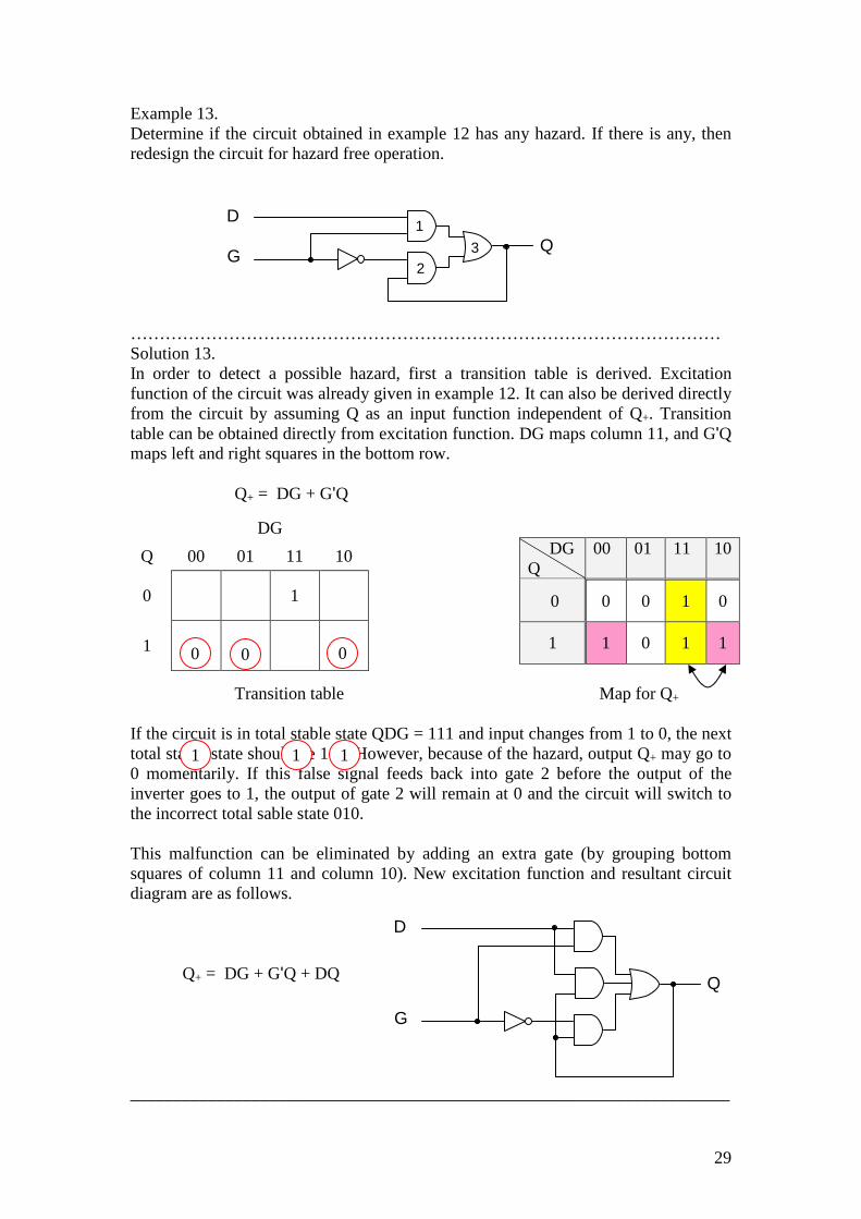
Example 13. Determine if the circuit obtained in example 12 has any hazard. If there is any, then redesign the circuit for hazard free operation. ………………………………………………………………………………………… Solution 13. In order to detect a possible hazard, first a transition table is derived. Excitation function of the circuit was already given in example 12. It can also be derived directly from the circuit by assuming Q as an input function independent of Q+. Transition table can be obtained directly from excitation function. DG maps column 11, and G'Q maps left and right squares in the bottom row.
Q+ = DG + G'Q
Transition table Map for Q+ If the circuit is in total stable state QDG = 111 and input changes from 1 to 0, the next total stable state should be 110. However, because of the hazard, output Q+ may go to 0 momentarily. If this false signal feeds back into gate 2 before the output of the inverter goes to 1, the output of gate 2 will remain at 0 and the circuit will switch to the incorrect total sable state 010. This malfunction can be eliminated by adding an extra gate (by grouping bottom squares of column 11 and column 10). New excitation function and resultant circuit diagram are as follows.
Q+ = DG + G'Q + DQ
_____________________________________________________________________
DG
Q 00 01 11 10
0
1
1
0
DG Q
00 01 11 10
0 0 0 1 0
1 1 0 1 1 0 0 0
1 1 1
D
G Q
1
2
3
D
G
Q